Embed Size (px)
Citation preview
www.foedisch.de
Title topic of Brochure
Complete Device NameXYZ 00 AB APPLICATION BROCHURE
Continuous emission monitoring system on ships
Multi component analyser system maritimeMCA 10 maritime APPLICATION BROCHURE
© Dr. Födisch Umweltmesstechnik AG 2
ABOUT US
Dr. Födisch Umweltmesstechnik AG is a leading manufacturer of emission monitoring devices for dust concentration, gas concentration and flow velocity. We are located in Markranstädt near Leipzig. Our R&D and production are “made in Germany”.
The 30 years’ expertise in developing and manufacturing emission and process measurement technology, combined with excellent knowledge in the field of environmental laws and regulations enable us to create optimum customised solutions for clients worldwide. This is supported by our Chinese subsidiary Dr. Foedisch Instruments (Hangzhou) Co., Ltd as well as our numerous distributors and service partners who guarantee short and quick routes to customers.
All dust measuring devices are developed, tested and calibrated in the dust channel of Dr. Födisch Umweltmesstechnik AG in Germany. As well, the gas analytics laboratory is equipped with comprehensive measurement techniques in order to determine the properties of substances, to calibrate measuring systems and to investigate basics in IR photometry and UV spectroscopy.
The gas analysers of Dr. Födisch Umweltmesstechnik AG comply with the most stringent European emission monitoring regulations. They own QAL1 approval according to EN 14181:2014 certified by TÜV from Germany and by CSA Group (MCERTS) from UK.
Our portfolio of certified gas analysers comprises hotwet and colddry gas measurement technology based on IR and UV measuring methods as well as analysers for stationary and mobile use.
Apart from the emission measuring devices we offer complete solutions for industries, which means our engineers do planning, installation and maintenance services as well as support with approval procedures. Our clientele are operators of combustion plants, e.g. power plants, incineration plants, cement plants, crematories as well as systems in the chemical/ petrochemical and metallurgical industry. A special strength of our company is the development of nonstandard solutions for challenging measuring tasks – this is the guiding principle of Dr. Födisch Umweltmess technik AG.
Headquarters of Dr. Födisch Umweltmesstechnik AG, Germany
MCA 10 maritime
3Application Brochure EN 07/2021
BACKGROUND
International shipping is a reliable, cost-effective means of global trade for many goods. It transports more than 90 % of world trade. This does not remain without consequences for the world's oceans. The task of the International Maritime Organisation (IMO), as a special UN agency, is therefore to define standards for safety, security and the environment.
With the help of the "International Convention for the Prevention of Pollution from Ships (MARPOL)", it has been possible to create internationally recognised, uniform standards.
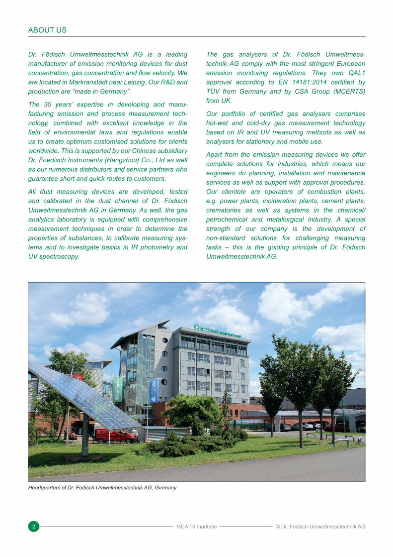
Annex VI of the MARPOL Convention explicitly addresses the issue of air pollution. It does not only set global emission limits, but also defines so-called "emission control areas" (ECAs) in which stricter requirements apply. These regulated areas include the North Sea and Baltic Sea coasts in Europe as well as the North American coasts and Caribbean coast. Other regions will follow in the future.
NOxRegulation 13 of Annex VI contains the control of nitrogen oxide emissions from marine diesel engines. NOx emission limits apply to marine diesel engines > 130 kW depending on the rated speed of the engine.
The verification is carried out according to the technical NOx regulation 2008 [Decision MEPC.177(58) and MEPC.251.66 of the Marine Environment Protection Committee] in compliance with the TIER I/II/III standards.
The valid NOx emission value for marine diesel engines is determined via test cycles and documented in an engine certification (EIAPP certificate). However, the technical NOx regulation does not require continuous NOx emission measurement on board, as is the case for combustion plants on shore.
SOxRegulation 14 of Annex VI defines maximum permis-sible sulphur contents for heavy fuel oil both for the open oceans and for the ECAs of the coastal regions.
In conjunction with the Marine Environment Protection Committee's decision (MEPC.259(68)), guidelines are defined for the use of exhaust gas cleaning systems and their monitoring. Corresponding SO2 / CO2 ratios are defined for different sulphur contents in the oil and operators have to provide proof of compliance based on the ratio of SO2 (ppm) / CO2 (% v/v) in the exhaust gas. This results in the requirement for continuous measurement of SO2 / CO2 on board. The values are to be recorded and submitted to the official authorities if required.
Emission Control Areas (ECAs) (Source: IFPEN)
Emission control areasPossible future emission control areas
MCA 10 maritime
© Dr. Födisch Umweltmesstechnik AG 4
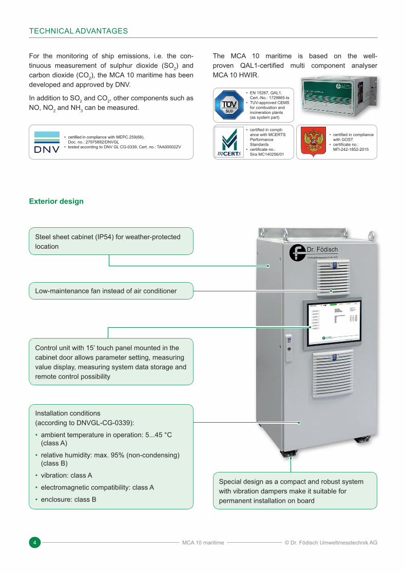
For the monitoring of ship emissions, i.e. the con-tinuous measurement of sulphur dioxide (SO2) and carbon dioxide (CO2), the MCA 10 maritime has been developed and approved by DNV.
In addition to SO2 and CO2, other components such as NO, NO2 and NH3 can be measured.
The MCA 10 maritime is based on the well-proven QAL1-certified multi component analyser MCA 10 HWIR.
• certified in compli ance with MEPC.259(68), Doc. no.: 27975892/DNVGL
• tested according to DNV GL CG-0339, Cert. no.: TAA00002ZV
Control unit with 15’ touch panel mounted in the cabinet door allows parameter setting, measuring value display, measuring system data storage and remote control possibility
Installation conditions (according to DNVGL-CG-0339):
• ambient temperature in operation: 5...45 °C (class A)
• relative humidity: max. 95% (non-condensing) (class B)
• vibration: class A
• electromagnetic compatibility: class A
• enclosure: class B
Low-maintenance fan instead of air conditioner
Special design as a compact and robust system with vibration dampers make it suitable for permanent installation on board
Steel sheet cabinet (IP54) for weather- protected location
TECHNICAL ADVANTAGES
Exterior design
• certified in compli-ance with MCERTS Performance Standards
• certificate no.: Sira MC140256/01
• certified in compliance with GOST
• certificate no.: МП-242-1852-2015
• EN 15267, QAL1, Cert.-No.: 1729865-ts
• TUV-approved CEMS for combustion and incineration plants (as system part)
MCA 10 maritime
5Application Brochure EN 07/2021
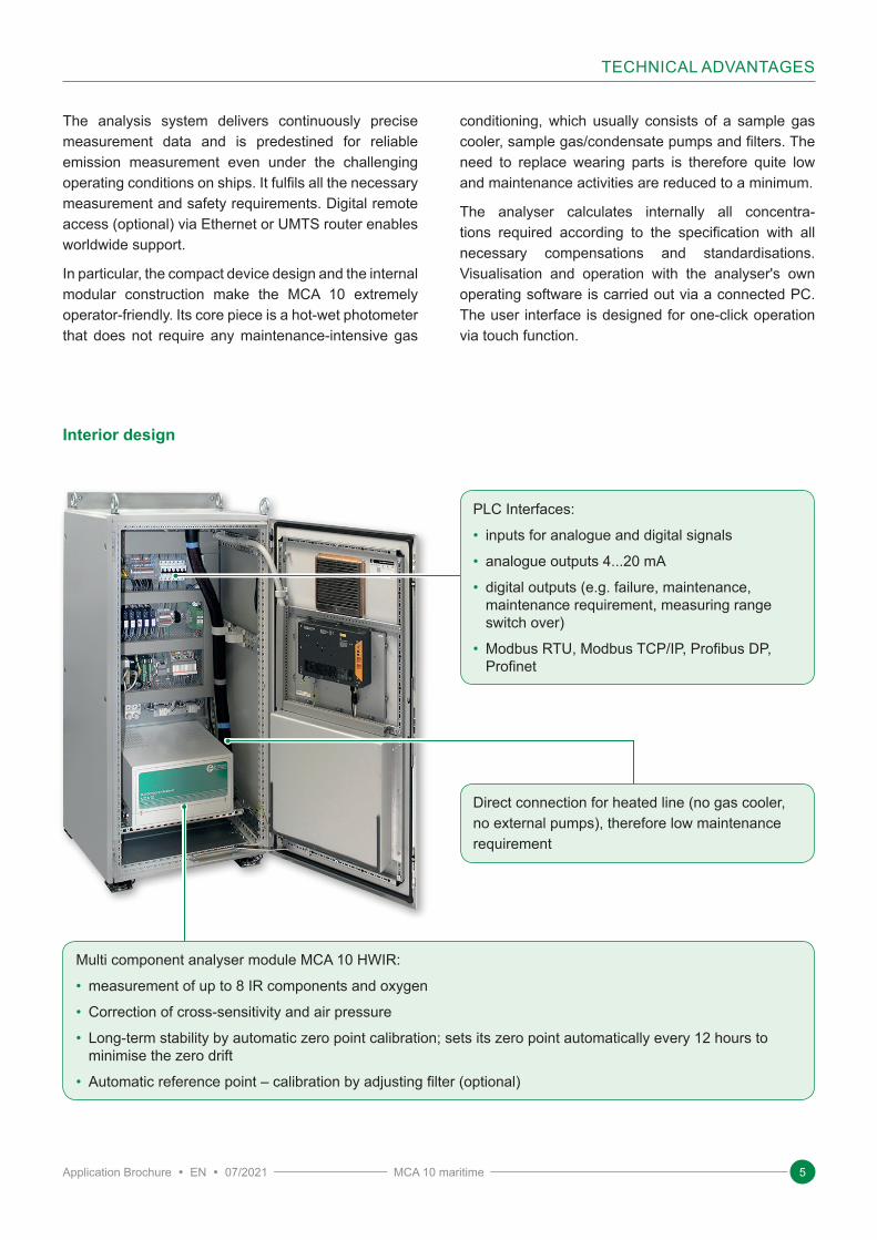
PLC Interfaces:
• inputs for analogue and digital signals
• analogue outputs 4...20 mA
• digital outputs (e.g. failure, maintenance, maintenance requirement, measuring range switch over)
• Modbus RTU, Modbus TCP/IP, Profibus DP, Profinet
Direct connection for heated line (no gas cooler, no external pumps), therefore low maintenance requirement
Multi component analyser module MCA 10 HWIR:
• measurement of up to 8 IR components and oxygen
• Correction of cross-sensitivity and air pressure
• Long-term stability by automatic zero point calibration; sets its zero point automatically every 12 hours to minimise the zero drift
• Automatic reference point – calibration by adjusting filter (optional)
The analysis system delivers continuously precise measurement data and is predestined for reliable emission measurement even under the challenging operating conditions on ships. It fulfils all the necessary measurement and safety requirements. Digital remote access (optional) via Ethernet or UMTS router enables worldwide support.
In particular, the compact device design and the internal modular construction make the MCA 10 extremely operator-friendly. Its core piece is a hot-wet photometer that does not require any maintenance-intensive gas
conditioning, which usually consists of a sample gas cooler, sample gas/condensate pumps and filters. The need to replace wearing parts is therefore quite low and maintenance activities are reduced to a minimum.
The analyser calculates internally all concentra-tions required according to the specification with all necessary compensations and standardisations. Visualisation and operation with the analyser's own operating software is carried out via a connected PC. The user interface is designed for one-click operation via touch function.
TECHNICAL ADVANTAGES
Interior design
MCA 10 maritime
© Dr. Födisch Umweltmesstechnik AG 6
The MCA 10 maritime is an extractive hot-wet gas analyser system. The gas path from sampling probe, via sampling line to the measuring cell inside the analyser is completely heated in a regulated way (185 °C). The sample gas is conveyed via the ejector integrated in the gas distribution block at the gas analyser. This means that the system requires neither an external sample gas pump nor a sample gas cooler for conditioning the sample gas. Nor is there any condensate.
The moisture contained in the exhaust gas is also measured for cross-sensitivity correction of the IR components and can be output if required.
Even high concentrations do not cause a measurement problem. This makes the system extremely simple in design and robust in application.
After the measurement, the sample gas is led out of the system again (via PTFE or heated exhaust gas line, depending on the application) and can be fed back into the process if necessary.
The MCA 10 maritime measures directly SO2 and CO2, but can be equipped additionally with CO, NO2 or NH3 amongst others.
SYSTEM DESIGN
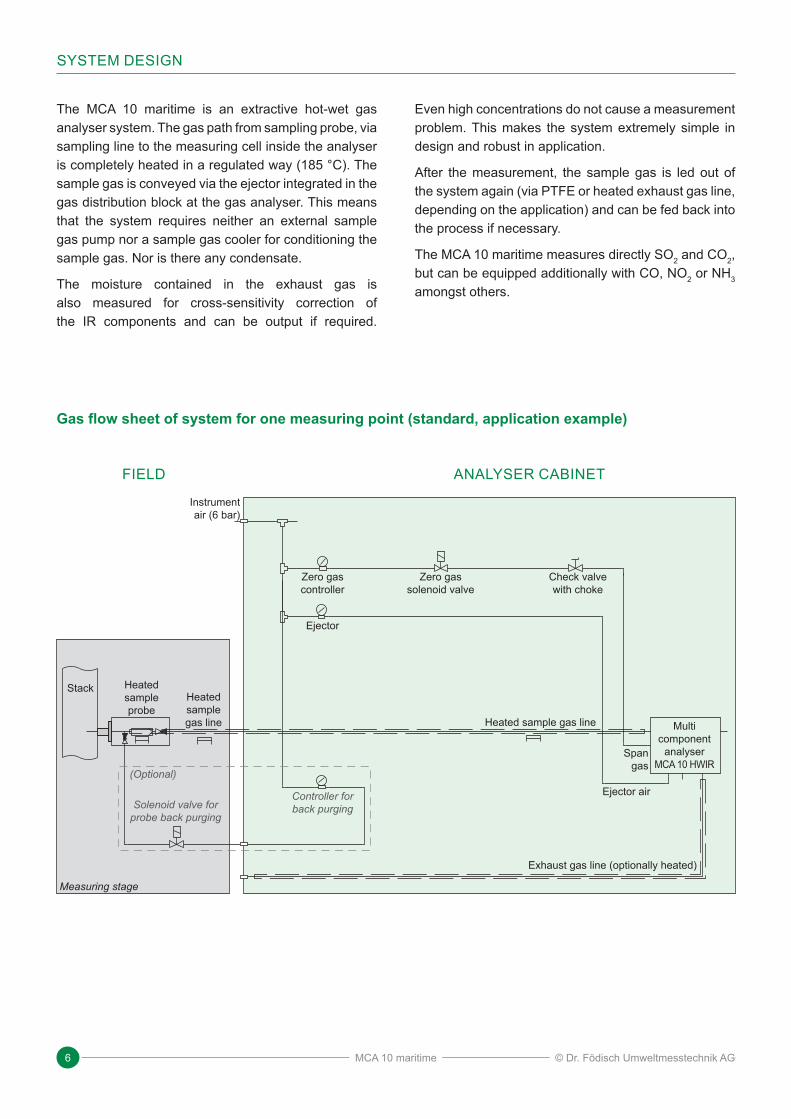
Measuring stage
Multi component
analyser MCA 10 HWIR
Span gas
Ejector air
Instrument air (6 bar)
Gas flow sheet of system for one measuring point (standard, application example)
Exhaust gas line (optionally heated)
FIELD ANALYSER CABINET
Stack Heated sample probe
Heated sample gas line
Zero gas controller
Controller for back purging
Ejector
Zero gas solenoid valve
Check valve with choke
Solenoid valve for probe back purging
Heated sample gas line
(Optional)
MCA 10 maritime
7Application Brochure EN 07/2021
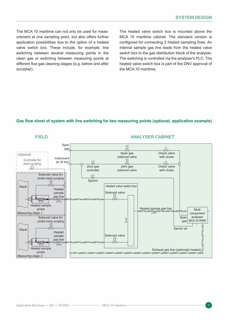
The MCA 10 maritime can not only be used for meas-urement at one sampling point, but also offers further application possibilities due to the option of a heated valve switch box. These include, for example, line switching between several measuring points in the clean gas or switching between measuring points at different flue gas cleaning stages (e.g. before and after scrubber).
The heated valve switch box is mounted above the MCA 10 maritime cabinet. The standard version is configured for connecting 2 heated sampling lines. An internal sample gas line leads from the heated valve switch box to the gas distribution block of the analyser. The switching is controlled via the analyser's PLC. The heated valve switch box is part of the DNV approval of the MCA 10 maritime.
SYSTEM DESIGN
Measuring stage 2
Measuring stage 1Multi
component analyser
MCA 10 HWIRSpan
gas
Ejector air
Span gas
Instrument air (6 bar)
Gas flow sheet of system with line switching for two measuring points (optional, application example)
Exhaust gas line (optionally heated)
FIELD ANALYSER CABINET
Stack
Stack
Heated sample probe
Heated sample probe
Heated sample gas line
Heated sample gas line
Zero gas controller
Ejector
Zero gas solenoid valve
Span gas solenoid valve
Check valve with choke
Check valve with choke
Solenoid valve for probe back purging
Solenoid valve for probe back purging
(Optional)
Controller for back purging
Heated valve switch box
Heated sample gas line
Solenoid valve
Solenoid valve
MCA 10 maritime
© Dr. Födisch Umweltmesstechnik AG 8
TECHNICAL DATA
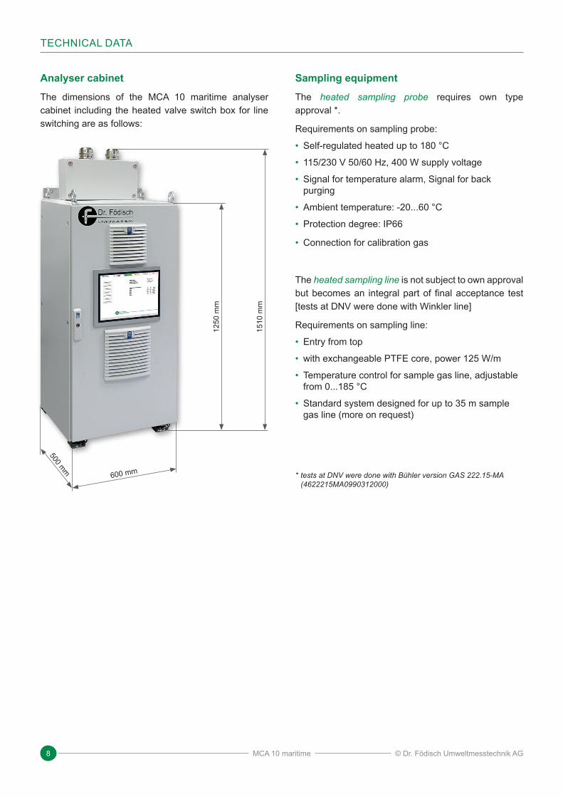
Analyser cabinetThe dimensions of the MCA 10 maritime analyser cabinet including the heated valve switch box for line switching are as follows:
Sampling equipmentThe heated sampling probe requires own type approval *.
Requirements on sampling probe:
• Self-regulated heated up to 180 °C
• 115/230 V 50/60 Hz, 400 W supply voltage
• Signal for temperature alarm, Signal for back purging
• Ambient temperature: -20...60 °C
• Protection degree: IP66
• Connection for calibration gas
The heated sampling line is not subject to own approval but becomes an integral part of final acceptance test [tests at DNV were done with Winkler line]
Requirements on sampling line:
• Entry from top
• with exchangeable PTFE core, power 125 W/m
• Temperature control for sample gas line, adjustable from 0...185 °C
• Standard system designed for up to 35 m sample gas line (more on request)
* tests at DNV were done with Bühler version GAS 222.15MA (4622215MA0990312000)
1250
mm
1510
mm
600 mm
500 mm
MCA 10 maritime
9Application Brochure EN 07/2021
TECHNICAL DATA
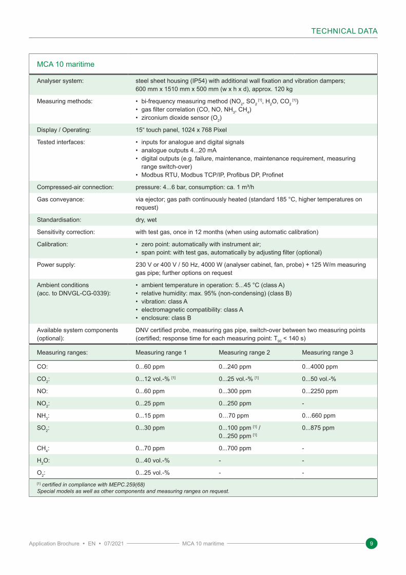
MCA 10 maritime
Analyser system: steel sheet housing (IP54) with additional wall fixation and vibration dampers; 600 mm x 1510 mm x 500 mm (w x h x d), approx. 120 kg
Measuring methods: • bi-frequency measuring method (NO2, SO2 [1], H2O, CO2
[1])• gas filter correlation (CO, NO, NH3, CH4)• zirconium dioxide sensor (O2)
Display / Operating: 15“ touch panel, 1024 x 768 Pixel
Tested interfaces: • inputs for analogue and digital signals• analogue outputs 4...20 mA• digital outputs (e.g. failure, maintenance, maintenance requirement, measuring
range switch-over)• Modbus RTU, Modbus TCP/IP, Profibus DP, Profinet
Compressed-air connection: pressure: 4...6 bar, consumption: ca. 1 m³/h
Gas conveyance: via ejector; gas path continuously heated (standard 185 °C, higher temperatures on request)
Standardisation: dry, wet
Sensitivity correction: with test gas, once in 12 months (when using automatic calibration)
Calibration: • zero point: automatically with instrument air;• span point: with test gas, automatically by adjusting filter (optional)
Power supply: 230 V or 400 V / 50 Hz, 4000 W (analyser cabinet, fan, probe) + 125 W/m measuring gas pipe; further options on request
Ambient conditions (acc. to DNVGL-CG-0339):
• ambient temperature in operation: 5...45 °C (class A)• relative humidity: max. 95% (non-condensing) (class B)• vibration: class A• electromagnetic compatibility: class A• enclosure: class B
Available system components (optional):
DNV certified probe, measuring gas pipe, switch-over between two measuring points (certified; response time for each measuring point: T90 < 140 s)
Measuring ranges: Measuring range 1 Measuring range 2 Measuring range 3
CO: 0...60 ppm 0...240 ppm 0...4000 ppm
CO2: 0...12 vol.-% [1] 0...25 vol.-% [1] 0...50 vol.-%
NO: 0...60 ppm 0...300 ppm 0...2250 ppm
NO2: 0...25 ppm 0...250 ppm -
NH3: 0...15 ppm 0…70 ppm 0…660 ppm
SO2: 0...30 ppm 0...100 ppm [1] /0...250 ppm [1]
0...875 ppm
CH4: 0...70 ppm 0...700 ppm -
H2O: 0...40 vol.-% - -
O2: 0...25 vol.-% - -[1] certified in compli ance with MEPC.259(68)Special models as well as other components and measuring ranges on request.
MCA 10 maritime

© Dr. Födisch Umweltmesstechnik AG 10
NOTES
MCA 10 maritime
11Application Brochure EN 07/2021
NOTES
MCA 10 maritime
www.foedisch.de© Dr. Födisch Umweltmesstechnik AG
Dr. Födisch Umweltmesstechnik AG
E-mail: [email protected]: +49 34205 755-0 Fax: +49 34205 755-40Zwenkauer Strasse 159 04420 Markranstädt Germany