Embed Size (px)
Citation preview

Belt Driven Leaf CollectorBelt Driven Leaf CollectorLCT650LCT650
ODB Company5118 Glen Alden DriveRichmond, VA 23231
800-446-9823www.leafcollector.com
Owner's ManualSafety Manual
Pre-Operating ManualOperating Manual
Maintenance ManualService ManualParts Catalog
800-446-9823
ODB COMPODB COMPODB COMPODB COMPODB COMPANYANYANYANYANY
IMPROPER USE OF ANY MACHINE CANRESULT IN SERIOUS INJURY!
STUDY AND FOLLOW ALL SAFETYPRECAUTIONS BEFORE OPERATING OR
REPAIRING UNIT
5118 Glen Alden DriveRichmond, VA 23231
DO NOT ATTEMPT TO OPERATEOR REPAIR
THE LEAF COLLECTOR WITHOUT FIRSTREADING AND UNDERSTANDING THIS
MANUAL
IF YOU HAVE ANY QUESTIONS CONCERNING THEINSTALLATION OR OPERATION OF THIS UNIT, PLEASE CALL
ODB FOR ASSISTANCE BEFORE ATTEMPTING TO REPAIR OROPERATE THE UNIT.
THIS MANUAL IS AN INTEGRAL PART OF THE LEAF COLLECTOR ANDSHOULD BE KEPT WITH THE UNIT WHEN IT IS SOLD.
TABLE OF CONTENTS
Read and understand this entire manual before operating, maintain-ing or repairing the leaf vacuum.
1.0 GENERAL SAFETY1.1 Safety Symbol Definitions1.2 Do’s and Don’t’s1.3 Training1.4 Safety Decal Listing and Part Numbers
2.0 PRE-OPERATING SECTION2.1 Instruments and Controls2.2 Safe Operations2.3 Preparation for Operation2.4 Pre-Transport Checks2.5 Protective Equipment and Clothing2.6 Worksite Preparation
3.0 OPERATING SECTION3.1 Starting Engine3.2 Engaging PTO3.3 Vacuuming Leaves
4.0 MAINTENANCE SECTION4.1 Maintenance Overview4.2 Maintenance Interval Chart4.3 Lubrication4.4 Preventative Maintenance4.5 Torque Values4.6 Quick Reference Maintenance Chart
SAFETY, OPERATING AND MAINTENANCETABLE OF CONTENTS
ODB COMPODB COMPODB COMPODB COMPODB COMPANYANYANYANYANY 800-446-9823
TABLE OF CONTENTS
Read and understand this entire manual before operating, maintain-ing or repairing the leaf vacuum.
SAFETY, OPERATING AND MAINTENANCETABLE OF CONTENTS, continued;
ODB COMPODB COMPODB COMPODB COMPODB COMPANYANYANYANYANY 800-446-9823
5.0 SERVICE SECTIONSERVICE AND TROUBLESHOOTING
Service and RepairEngine Electrical TroubleshootingAuto PTO Adjustment GuideHydr. Boom TroubleshootingImpeller Installation/RemovalBelt Adjustment and Repl. GuideLiner Replacement Guide
WIRING DIAGRAMSEngine Wiring DiagramCircuit Board WiringTrailer Wiring DiagramBoom Pump Wiring Diagram
HOIST HYDRAULIC SYSTEMHydraulic Valve - 4 wayHydraulic System DiagramHoist Tips
6.0 PARTS BREAKDOWNSENGINE GROUP
Inst. Panel BreakdownAir Cleaner AssemblySheet Metal AssemblyEngine ExhaustRadiator AssemblyRemote Throttle Ass’y (OPTIONAL)Chaffe Eleminator (OPTIONAL)
CLUTCH GROUPClutch BreakdownAuto PTO BreakdownAuto PTO LinkageClutch Assist Breakdown
6.0 PARTS BREAKDOWNS, cont.;BLOWER HOUSING & DRIVE GROUP
Imp. & Blr Housing BreakdwonPedistal & Bearing AssemblyBlower Housing Face AssemblyExhaust Duct Assembly
TRAILER GROUPTrailer Bed AssemblyFuel Tank AssemblyTongue Assembly
HOSE BOOM GROUPHose Boom AssemblyIntake Hose AssemblyHydraulic Pump Assembly

1.0 GENERAL SAFETY
Read and understand this entire manual before operating, maintain-ing or repairing the leaf vacuum.
1.0 GENERAL SAFETY1.1 Safety Symbol Definitions1.2 Do’s and Don’t’s1.3 Training1.4 Safety Decal Listing and Part Numbers
1.0GENERALSAFETY
ODB COMPODB COMPODB COMPODB COMPODB COMPANYANYANYANYANY 800-446-9823
SAFETY PRECAUTIONS
!
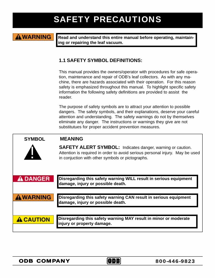
The purpose of safety symbols are to attract your attention to possibledangers. The safety symbols, and their explanations, deserve your carefulattention and understanding. The safety warnings do not by themselveseliminate any danger. The instructions or warnings they give are notsubstitutues for proper accident prevention measures.
SYMBOL MEANINGSAFETY ALERT SYMBOL: Indicates danger, warning or caution.Attention is required in order to avoid serious personal injury. May be usedin conjuction with other symbols or pictographs.
Read and understand this entire manual before operating, maintain-ing or repairing the leaf vacuum.
Disregarding this safety warning WILL result in serious equipmentdamage, injury or possible death.
Disregarding this safety warning CAN result in serious equipmentdamage, injury or possible death.
Disregarding this safety warning MAY result in minor or moderateinjury or property damage.
1.1 SAFETY SYMBOL DEFINITIONS:
This manual provides the owners/operator with procedures for safe opera-tion, maintenance and repair of ODB’s leaf collectors. As with any ma-chine, there are hazards associated with their operation. For this reasonsafety is emphasized throughout this manual. To highlight specific safetyinformation the following safety definitions are provided to assist thereader.
ODB COMPODB COMPODB COMPODB COMPODB COMPANYANYANYANYANY 800-446-9823
SAFETY PRECAUTIONS
DO NOT operate, maintain or repair this unit without having fully readand understood ALL the aspects of this manual.DO NOT ride, sit or stand on unit at anytime.DO NOT modify the leaf vacuum for any reasons to allow for riders.DO NOT operate the unit in a state of disrepair.DO NOT operate the unit with ANY guards or safety devices broken,missing, or inoperable.DO NOT operate the unit without wearing proper safety equipment.DO NOT operate this unit while under the influence of any alcohol ormedication.DO NOT operate this unit if you have a record of mental instability ordizziness which could result in injury to yourself or others.DO NOT operate this unit if you are under 18 years of age.DO NOT operate this unit without fully inspecting the unit for any dam-age or leakage.DO NOT operate if the unit has any excessive vibration.DO NOT operate unit with the inspection door limit switch damaged ormissing.DO NOT operate unit unless all hydraulic components such as hoses andfittings have been checked for leakage or damage.DO NOT operate unit unless it is properly attached to the tow vehicle.DO NOT tow unit without using all the safety chains.DO NOT tow unit with a damaged tongue.DO NOT fill fuel tank with engine running. Allow engine to cool for 5 min-utes before refueling.DO NOT operate unit if fuel is spilled or with fuel cap off.DO NOT smoke or weld near the unit.DO NOT run engine in an enclosed area.DO NOT place hands or feet near moving or rotating parts.DO NOT operate engine with an accumulation of grass, leaves or otherdebris on the engine.
Read and understand this entire manual before operating, maintain-ing or repairing the leaf vacuum.
1.2 DO’S AND DO NOT’S:
This section contains some general safety precautions to do and not to do.This is not an all inclusive list and and it is the responsibilty of the operatorto have proper training and use common sense in work situations.
1.
2.3.4.5.
6.7.
8.
9.10.
11.12.
13.
14.15.16.17.
18.19.20.21.22.
DO NOT:
ODB COMPODB COMPODB COMPODB COMPODB COMPANYANYANYANYANY 800-446-9823
SAFETY PRECAUTIONS
DO NOT run engine with air cleaner removed.DO NOT leave leaf machine unattended while in operation.DO NOT park machine on steep grade or slope.DO NOT vacuum a leaf pile without looking for foreign objects such asmetal, glass, plastic or large pieces of wood.DO NOT go under raised body without body prop in place for any reason.DO NOT collect leaves without the dump body lowered completely.DO NOT collect leaves with the rear doors open.DO NOT raise dump body near any power lines or low tree branches.DO NOT raise dump body on an uneven or soft surface.DO NOT lower dump body without a complete visual check of the bodyarea.DO NOT raise dump body without wheel chocks placed under the wheels.
23.24.25.26.
27.28.29.30.31.32.
33.
DO NOT, continued;
DO’s:
DO completely read and understand the owner’s manual before operat-ing, maintaining or repairing the leaf collector.DO follow engine and PTO manufacturer operating and maintenanceinstructions.DO check fuel lines and fittings frequently for cracks or leaks. Replaceif necessary.DO completely inspect the unit before leaving the service garage.DO check the tow tongue each day for cracks.DO inspect and be attentive to what is being vacuumed.DO check the impeller, liners and blower housing for cracks or holesdaily.DO remove the negative battery cable before doing any maintenanceon the unit.DO wear proper safety equipment as described in this manual.DO watch for pedestrians, animals and other foreign material whenvacuuming leaves.DO replace any worn or missing safety stickers immediately.DO insert the body prop before going under the raised body for any rea-son.
1.
2.
3.
4.5.6.7.
8.
9.10.
11.12.
ODB COMPODB COMPODB COMPODB COMPODB COMPANYANYANYANYANY 800-446-9823

SAFETY PRECAUTIONS
Improper use of the ODB leaf collector CAN result in severe per-sonal injury or death. All personnel using this leaf vacuum must betrained and qualified with all the operations, maintenance, repairand safety procedures defined in this manual.
1.3 TRAINING:
The warnings and procedures regarding safety in this manual are to beused as a guideline only. It is impossible to cover all the events that couldhappen in the vacuuming process. For this reason, it is vital that theowner accept the responsibility to implement a training program that willprovide every operator or mechanic the basic skills and knowledge tomake good judgement in all situations.
This training program must include the entire scope of hazards, precau-tions and government regulations encountered in the vacuuming process.The program should stress the need for regularly scheduled preventivemaintenance and detailed equipment safety checks.
ODB strongly recommends all training programs be documented to ensureall operators and mechanics receive initial training on not just the opera-tion but the safety features of the leaf collector.
ODB COMPODB COMPODB COMPODB COMPODB COMPANYANYANYANYANY
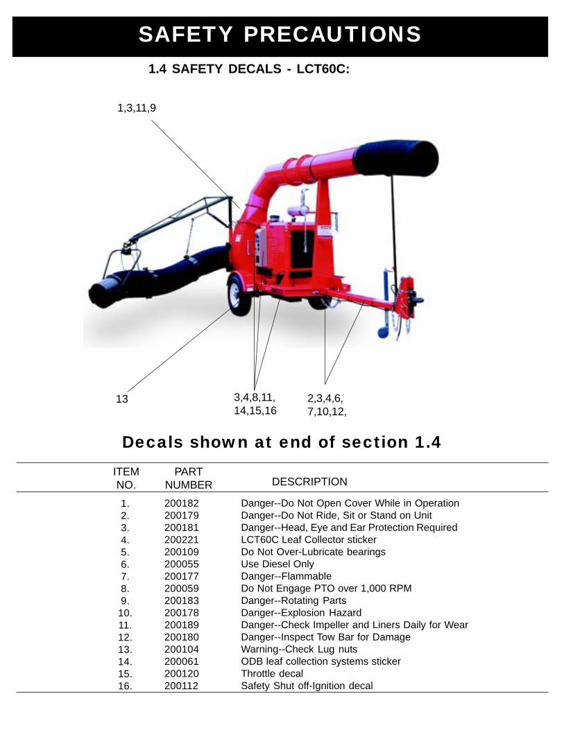
Danger--Do Not Open Cover While in OperationDanger--Do Not Ride, Sit or Stand on UnitDanger--Head, Eye and Ear Protection RequiredLCT60C Leaf Collector stickerDo Not Over-Lubricate bearingsUse Diesel OnlyDanger--FlammableDo Not Engage PTO over 1,000 RPMDanger--Rotating PartsDanger--Explosion HazardDanger--Check Impeller and Liners Daily for WearDanger--Inspect Tow Bar for DamageWarning--Check Lug nutsODB leaf collection systems stickerThrottle decalSafety Shut off-Ignition decal
1.2.3.4.5.6.7.8.9.
10.11.12.13.14.15.16.
ITEMNO.
PARTNUMBER DESCRIPTION
200182200179200181200221200109200055200177200059200183200178200189200180200104200061200120200112
Decals shown at end of section 1.4
1,3,11,9
3,4,8,11,14,15,16
2,3,4,6,7,10,12,
13
SAFETY PRECAUTIONS1.4 SAFETY DECALS - LCT60C:
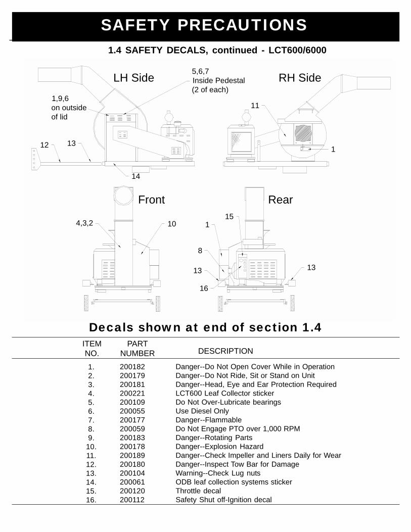
Danger--Do Not Open Cover While in OperationDanger--Do Not Ride, Sit or Stand on UnitDanger--Head, Eye and Ear Protection RequiredLCT600 Leaf Collector stickerDo Not Over-Lubricate bearingsUse Diesel OnlyDanger--FlammableDo Not Engage PTO over 1,000 RPMDanger--Rotating PartsDanger--Explosion HazardDanger--Check Impeller and Liners Daily for WearDanger--Inspect Tow Bar for DamageWarning--Check Lug nutsODB leaf collection systems stickerThrottle decalSafety Shut off-Ignition decal
1.2.3.4.5.6.7.8.9.
10.11.12.13.14.15.16.
ITEMNO.
PARTNUMBER DESCRIPTION
200182200179200181200221200109200055200177200059200183200178200189200180200104200061200120200112
Decals shown at end of section 1.4
LH Side5,6,7Inside Pedestal(2 of each)
1,9,6on outsideof lid
11
11312
1
8
13 13
104,3,2
RH Side
Front Rear
14
15
16
SAFETY PRECAUTIONS1.4 SAFETY DECALS, continued - LCT600/6000
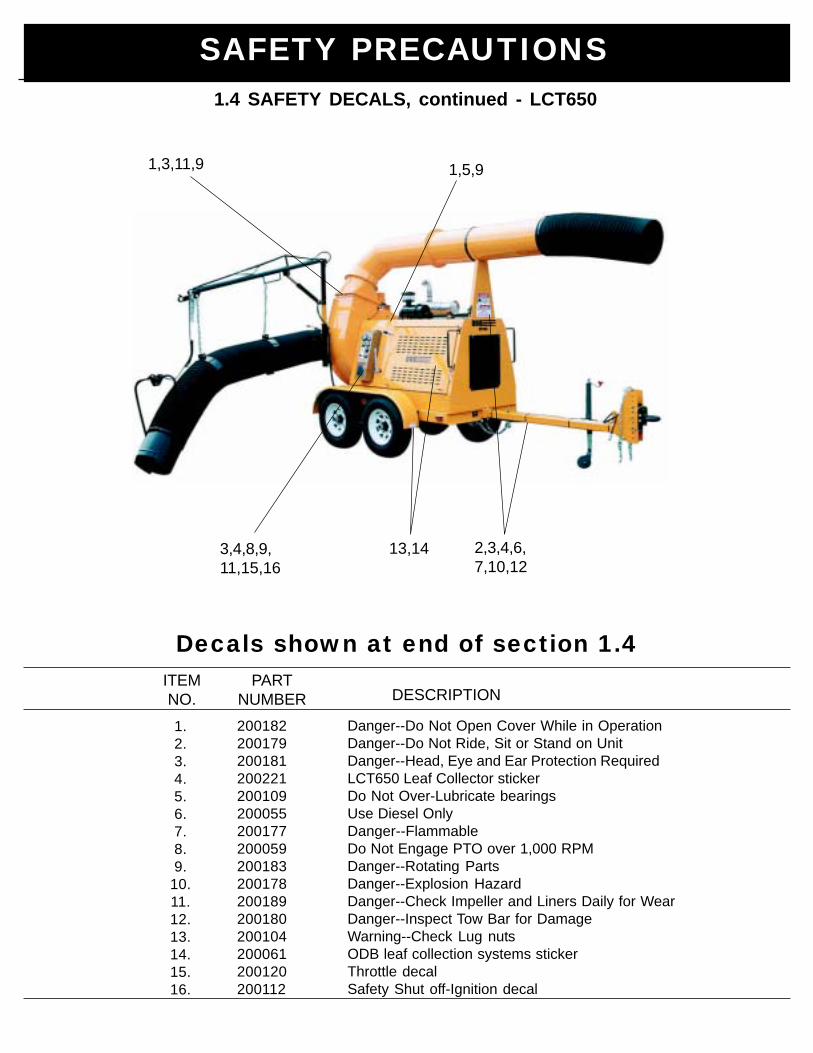
Danger--Do Not Open Cover While in OperationDanger--Do Not Ride, Sit or Stand on UnitDanger--Head, Eye and Ear Protection RequiredLCT650 Leaf Collector stickerDo Not Over-Lubricate bearingsUse Diesel OnlyDanger--FlammableDo Not Engage PTO over 1,000 RPMDanger--Rotating PartsDanger--Explosion HazardDanger--Check Impeller and Liners Daily for WearDanger--Inspect Tow Bar for DamageWarning--Check Lug nutsODB leaf collection systems stickerThrottle decalSafety Shut off-Ignition decal
1.2.3.4.5.6.7.8.9.
10.11.12.13.14.15.16.
ITEMNO.
PARTNUMBER DESCRIPTION
200182200179200181200221200109200055200177200059200183200178200189200180200104200061200120200112
Decals shown at end of section 1.4
1,3,11,9
3,4,8,9,11,15,16
2,3,4,6,7,10,12
13,14
1,5,9
SAFETY PRECAUTIONS1.4 SAFETY DECALS, continued - LCT650
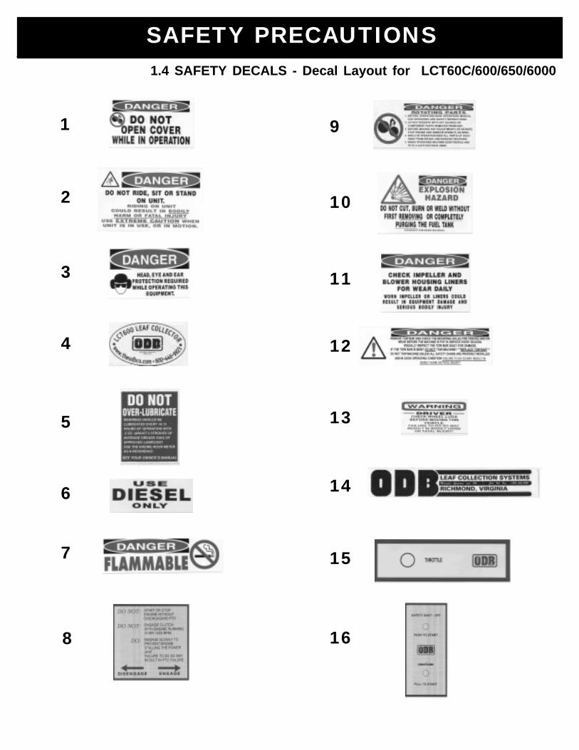
1
2
3
4
5
6
7
8
9
10
11
12
13
14
15
16
SAFETY PRECAUTIONS1.4 SAFETY DECALS - Decal Layout for LCT60C/600/650/6000
Read and understand this entire manual before operating, maintain-ing or repairing the leaf vacuum.
2.0 PRE-OPERATING SECTION2.1 Instruments and Controls2.2 Safe Operations2.3 Preparation for Operation2.4 Pre-Transport Checks2.5 Protective Equipment and Clothing2.6 Worksite Preparation
2.0Pre-Operating
Section
2.0 PRE-OPERATING SECTION
ODB COMPODB COMPODB COMPODB COMPODB COMPANYANYANYANYANY 800-446-9823

Pre-Operating Section
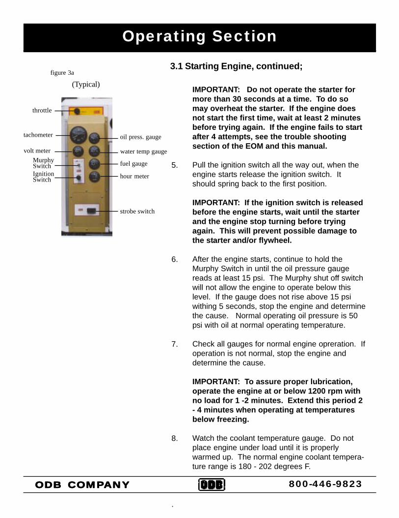
2.1 INSTRUMENTS AND CONTROLS:
Ignition Switch:Used to power the accessories and start the unit. Unitwill not start without Murphy switch depressed.ACCESSORIES - first positionSTARTER ENGAGE - second position (springs return tofirst position)
Murphy Switch:This switch overrides the low oil pressure and high tem-perature cutoff control. This switch must be depressedbefore the starter engages. After the engine starts, waitfor oil pressure to rise before releasing the button.
Throttle:This control provides positive locking and vernier adjust-ment of engine.
Tachometer:This gauge indicates the engine r.p.m’s. The sender islocated on the engine block
Volt Meter:The gauge shows the status of the engine chargingsystem. When the charging system is operating properlyit should read approximately 14 volts. If the gauge readsbelow 13 volts, the alternator is not charging the batteryand the system should be checked by a qualifiedtechnicican.
Oil Pressure Gauge:Confirms and indicates the presense and pressure ofengine oil. If the gauge reads low, it should be checkedby a qualified technician.
Engine Temperature:Indicates the engine coolant temperature. If the gaugereads over 240 degrees the unit should be checked by aqualified technician.
Hour Meter:Indicates the accumulated hours of the the engine. Thisshould be used to schedule maintenance.
oil press. gauge
water temp gauge
fuel gauge
hour meter
tachometer
volt meterMurphySwitchIgnitionSwitch
strobe switch
(Typical)
Always make sure the PTO isdisengaged before starting unit.
throttle
ODB COMPODB COMPODB COMPODB COMPODB COMPANYANYANYANYANY 800-446-9823
Pre-Operating Section
ALL personnel using, maintaining or servicing this unit must betrained in all safety procedures outlined in this manual. Improper orcareless use of this equipment CAN result in personal injury ordeath.
2.2 SAFE OPERATIONS:
Operations shall be restricted to:
ODB COMPODB COMPODB COMPODB COMPODB COMPANYANYANYANYANY 800-446-9823
Properly trained, qualified and experienced operators and/or qualifiedand experienced maintenance and test personnel.
Trainees under the direct supervision of qualified and experiencepersonnel.
Qualified and experienced maintenance and service personnel.
1.
2.
3.
Operators who qualify to operate this equipment under the aboverestrictions shall also comply with the following physical require-ments:
Have good vision and the ability to read and understand this manualas well as all safety and operational decals on the equipment.
Be capable of hearing, with or without a hearing aid, at a levelneeded to safely operate this equipment.
A record of mental stability with no history of epileptic seizures, dizzi-ness, or any other disability that may result in injury to himself orothers.
If any of these requirements are not satisfied at any time, the personfailing to meet these requirements MUST NOT OPERATE THISEQUIPMENT.
1.
2.
3.
Pre-Operating Section
ODB COMPODB COMPODB COMPODB COMPODB COMPANYANYANYANYANY 800-446-9823
2.2 SAFE OPERATIONS (continued):
Additional Requirements:
Each operator must demonstrate competence to understand all safetydecals, operator’s manuals, safety codes, applicable governmentregulations, and all other information applicable to the safe andproper operation of the leaf vacuum.
Each operator must demonstrate the ability to recognize an emer-gency situation that may arise during vacuuming operations and theknowledge and procedures to implement corrective action.
Each operator must demonstrate or provide evidence ofqualificatation and experience prior to operating the leaf vacuum.
Each operator must be able to recognize existing or potential prob-lems regarding the mechanical integrity of the leaf vacuum and reportany maintenance requirements to the supervisor in charge.
Each operator must wear the proper personal clothing and safetygear. (Refer to SAFETY PRECAUTIONS Section 5.4)
Operators must not be physically or mentally fatigued.
Operators must not be under the direct or indirect influence of alcoholand/or drugs. This includes prescription drugs that could causedrowsiness, dizziness, or any other condition that would impair theirability to operate or use this equipment in a safe manner.
1.
2.
3.
4.
5.
6.
7.
Pre-Operating Section
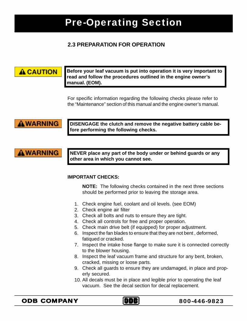
Before your leaf vacuum is put into operation it is very important toread and follow the procedures outlined in the engine owner’smanual. (EOM).
2.3 PREPARATION FOR OPERATION
ODB COMPODB COMPODB COMPODB COMPODB COMPANYANYANYANYANY 800-446-9823
For specific information regarding the following checks please refer tothe “Maintenance” section of this manual and the engine owner’s manual.
IMPORTANT CHECKS:
1.2.3.4.5.6.
7.
8.
9.
10.
DISENGAGE the clutch and remove the negative battery cable be-fore performing the following checks.
NEVER place any part of the body under or behind guards or anyother area in which you cannot see.
NOTE: The following checks contained in the next three sectionsshould be performed prior to leaving the storage area.
Check engine fuel, coolant and oil levels. (see EOM)Check engine air filterCheck all bolts and nuts to ensure they are tight.Check all controls for free and proper operation.Check main drive belt (if equipped) for proper adjustment.Inspect the fan blades to ensure that they are not bent , deformed,fatiqued or cracked.Inspect the intake hose flange to make sure it is connected correctlyto the blower housing.Inspect the leaf vacuum frame and structure for any bent, broken,cracked, missing or loose parts.Check all guards to ensure they are undamaged, in place and prop-erly secured.All decals must be in place and legible prior to operating the leafvacuum. See the decal section for decal replacement.
Pre-Operating Section
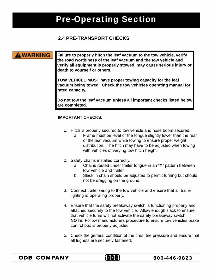
Failure to properly hitch the leaf vacuum to the tow vehicle, verifythe road worthiness of the leaf vacuum and the tow vehicle andverify all equipment is properly stowed, may cause serious injury ordeath to yourself or others.
TOW VEHICLE MUST have proper towing capacity for the leafvacuum being towed. Check the tow vehicles operating manual forrated capacity.
Do not tow the leaf vacuum unless all important checks listed beloware completed.
2.4 PRE-TRANSPORT CHECKS
ODB COMPODB COMPODB COMPODB COMPODB COMPANYANYANYANYANY 800-446-9823
IMPORTANT CHECKS:
1.
2.
3.
4.
5.
Hitch is properly secured to tow vehicle and hose boom secured. a. Frame must be level or the tongue slightly lower than the rear
of the leaf vacuum while towing to ensure proper weightdistribution. The hitch may have to be adjusted when towingwith vehicles of varying tow hitch height.
Safety chains installed correctly. a. Chains routed under trailer tongue in an “X” pattern between
tow vehicle and trailer. b. Slack in chain should be adjusted to permit turning but should
not be dragging on the ground.
Connect trailer wiring to the tow vehicle and ensure that all trailerlighting is operating properly.
Ensure that the safety breakaway switch is functioning properly andattached securely to the tow vehicle. Allow enough slack to ensurethat vehicle turns will not activate the safety breakaway switch.NOTE: Follow manufacturers procedure to ensure tow vehicles brakecontrol box is properly adjusted.
Check the general condition of the tires, tire pressure and ensure thatall lugnuts are securely fastened.
Pre-Operation Section
ODB COMPODB COMPODB COMPODB COMPODB COMPANYANYANYANYANY 800-446-9823
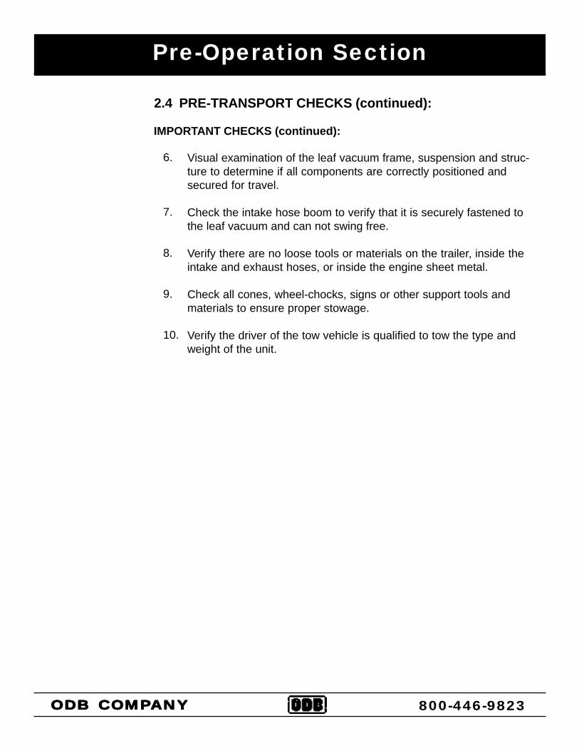
2.4 PRE-TRANSPORT CHECKS (continued):
IMPORTANT CHECKS (continued):
Visual examination of the leaf vacuum frame, suspension and struc-ture to determine if all components are correctly positioned andsecured for travel.
Check the intake hose boom to verify that it is securely fastened tothe leaf vacuum and can not swing free.
Verify there are no loose tools or materials on the trailer, inside theintake and exhaust hoses, or inside the engine sheet metal.
Check all cones, wheel-chocks, signs or other support tools andmaterials to ensure proper stowage.
Verify the driver of the tow vehicle is qualified to tow the type andweight of the unit.
6.
7.
8.
9.
10.
Pre-Operating Section
2.5 PERSONAL PROTECTIVE EQUIPMENT AND CLOTHING
ODB COMPODB COMPODB COMPODB COMPODB COMPANYANYANYANYANY 800-446-9823
IMPORTANT CHECKS:
Anyone operating ODB’s leaf vacuums MUST wear appropriateprotective equipment and clothing to protect them from injury duringoperations.
1.
2.
3.
4.
5.
6.
7.
Head Protection: Hard hats without under-chin strapping.
Eye Protection: Wraparound goggle type eye protection held inplace with an elastic band around the head or a hard hatmounted face shield, which provides full protection of the face.Eye protection must meet ANSI Z87.1 standards.
Hearing Protection: plug type or “muff type” ear protectionshould be worn at all times while operating the unit.
Breathing Protection: Paper filter type dust masks should beworn to protect from dirt and dust particles during the vacuumingprocess.
Reflective Vests: Highly visible vests should be worn so motor-ists can see see the operator in all weather and lighting condi-tions.
Work Gloves: Gloves should be worn to protect the hands andwrists from debris.
Steel Toed Boots: should be worn to protect the feet.
Work clothes MUST be close fitting, but not restrictive of move-ment, without any loose parts that could be entangled in any partsof the leaf vacuum. This includes items such as jewelry, chainsand backpacks.
PROTECTIVE EQUIPMENT:
Always wear proper safety equipment as outlined below, not wear-ing such equipment CAN result in serious personal injury or pos-sible death.
Pre-Operating Section
2.6 WORK SITE PREPARATION
ODB COMPODB COMPODB COMPODB COMPODB COMPANYANYANYANYANY 800-446-9823
1.
2.
3.
4.
5.
6.
7.
An inspection of the leaves to be vacuumed must be done prior tothe vacuuming process. We realize that it is impossible to com-pletely inspect every inch of leaves being vacuumed, but it isimperative that all leaves be inpsected for obvious dangerousmaterial before vacuuming.
The operator should never be in the line of traffic, the operatorshould work on the shoulder whenever possible.
The operators should place cones or other barriers to provideadequate warnings to vehicles and pedestrians that vacuumingis in progress.
Strobe lights on the leaf vacuum and on the tow vehicle should beon at all times for high visibility.
Confirm that all operators are wearing proper clothes and per-sonal protective equipment.
Restrict all personnel, except the operator from the area near theleaf vacuum. DO NOT allow pedestrians, children or animalsnear the work area.
Make sure that the exhaust hose fits properly into the box con-tainer so that all debris is blown into the box container.
The following guidelines must be followed to insure safety.
Never place any part of the body under or behind guards or anyother visually obscured area.
Making sure the leaves are clear of possible dangerous material iscritical to safe vacuuming. Vacuuming up metal, glass, rocks orother dangerous material CAN cause serious damage to the equip-ment or personal injury.
3.0 OPERATING SECTION
Read and understand this entire manual before operating, maintain-ing or repairing the leaf vacuum.
3.0 OPERATING SECTION3.1 Starting Engine3.2 Engaging PTO3.3 Vacuuming Leaves
ODB COMPODB COMPODB COMPODB COMPODB COMPANYANYANYANYANY 800-446-9823
Operating Section
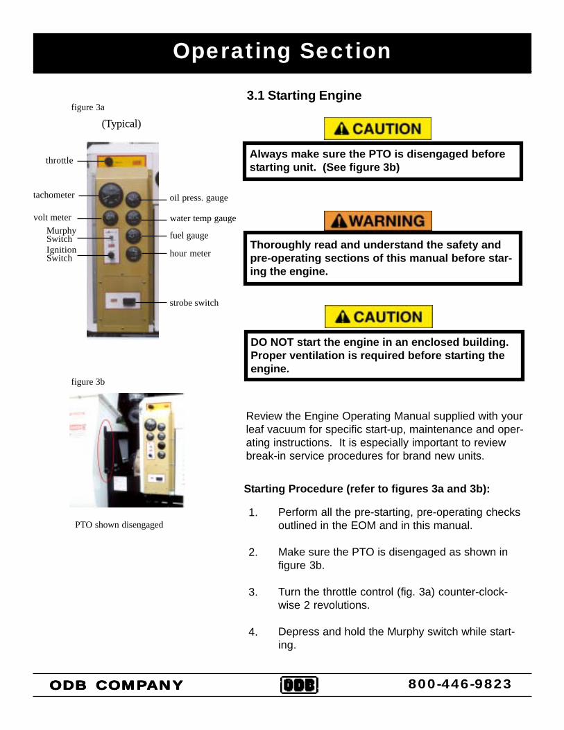
3.1 Starting Engine
Review the Engine Operating Manual supplied with yourleaf vacuum for specific start-up, maintenance and oper-ating instructions. It is especially important to reviewbreak-in service procedures for brand new units.
oil press. gauge
water temp gauge
fuel gauge
hour meter
tachometer
volt meterMurphySwitchIgnitionSwitch
strobe switch
(Typical)
Always make sure the PTO is disengaged beforestarting unit. (See figure 3b)throttle
ODB COMPODB COMPODB COMPODB COMPODB COMPANYANYANYANYANY
PTO shown disengaged
Thoroughly read and understand the safety andpre-operating sections of this manual before star-ing the engine.
figure 3b
figure 3a
Perform all the pre-starting, pre-operating checksoutlined in the EOM and in this manual.
Make sure the PTO is disengaged as shown infigure 3b.
Turn the throttle control (fig. 3a) counter-clock-wise 2 revolutions.
Depress and hold the Murphy switch while start-ing.
DO NOT start the engine in an enclosed building.Proper ventilation is required before starting theengine.
Starting Procedure (refer to figures 3a and 3b):
1.
2.
3.
4.
800-446-9823
3.1 Starting Engine, continued;
IMPORTANT: Do not operate the starter formore than 30 seconds at a time. To do somay overheat the starter. If the engine doesnot start the first time, wait at least 2 minutesbefore trying again. If the engine fails to startafter 4 attempts, see the trouble shootingsection of the EOM and this manual.
Pull the ignition switch all the way out, when theengine starts release the ignition switch. Itshould spring back to the first position.
IMPORTANT: If the ignition switch is releasedbefore the engine starts, wait until the starterand the engine stop turning before tryingagain. This will prevent possible damage tothe starter and/or flywheel.
After the engine starts, continue to hold theMurphy Switch in until the oil pressure gaugereads at least 15 psi. The Murphy shut off switchwill not allow the engine to operate below thislevel. If the gauge does not rise above 15 psiwithing 5 seconds, stop the engine and determinethe cause. Normal operating oil pressure is 50psi with oil at normal operating temperature.
Check all gauges for normal engine opreration. Ifoperation is not normal, stop the engine anddetermine the cause.
IMPORTANT: To assure proper lubrication,operate the engine at or below 1200 rpm withno load for 1 -2 minutes. Extend this period 2- 4 minutes when operating at temperaturesbelow freezing.
Watch the coolant temperature gauge. Do notplace engine under load until it is properlywarmed up. The normal engine coolant tempera-ture range is 180 - 202 degrees F.
5.
6.
7.
8.
.
oil press. gauge
water temp gauge
fuel gauge
hour meter
tachometer
volt meterMurphySwitchIgnitionSwitch
strobe switch
(Typical)
throttle
figure 3a
ODB COMPODB COMPODB COMPODB COMPODB COMPANYANYANYANYANY 800-446-9823
Operating Section
Operating Section
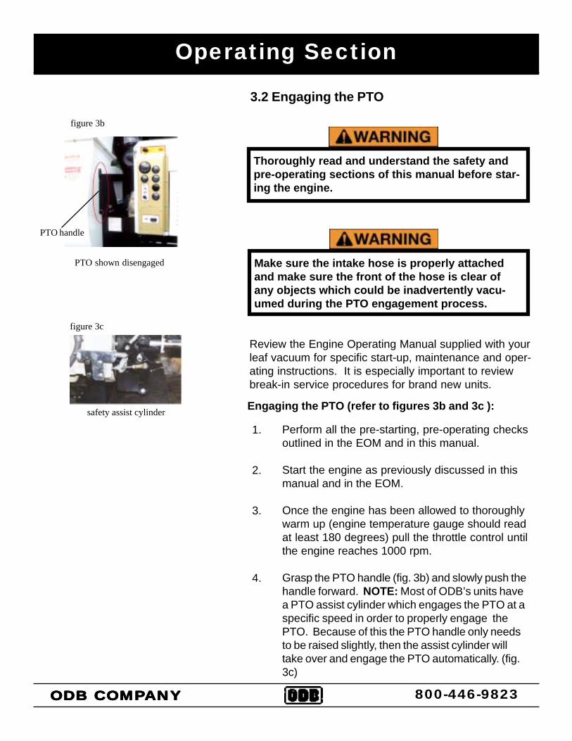
3.2 Engaging the PTO
Review the Engine Operating Manual supplied with yourleaf vacuum for specific start-up, maintenance and oper-ating instructions. It is especially important to reviewbreak-in service procedures for brand new units.
ODB COMPODB COMPODB COMPODB COMPODB COMPANYANYANYANYANY
PTO shown disengaged
Thoroughly read and understand the safety andpre-operating sections of this manual before star-ing the engine.
figure 3b
Perform all the pre-starting, pre-operating checksoutlined in the EOM and in this manual.
Start the engine as previously discussed in thismanual and in the EOM.
Once the engine has been allowed to thoroughlywarm up (engine temperature gauge should readat least 180 degrees) pull the throttle control untilthe engine reaches 1000 rpm.
Grasp the PTO handle (fig. 3b) and slowly push thehandle forward. NOTE: Most of ODB’s units havea PTO assist cylinder which engages the PTO at aspecific speed in order to properly engage thePTO. Because of this the PTO handle only needsto be raised slightly, then the assist cylinder willtake over and engage the PTO automatically. (fig.3c)
Engaging the PTO (refer to figures 3b and 3c ):
1.
2.
3.
4.
800-446-9823
Make sure the intake hose is properly attachedand make sure the front of the hose is clear ofany objects which could be inadvertently vacu-umed during the PTO engagement process.
figure 3c
safety assist cylinder
PTO handle
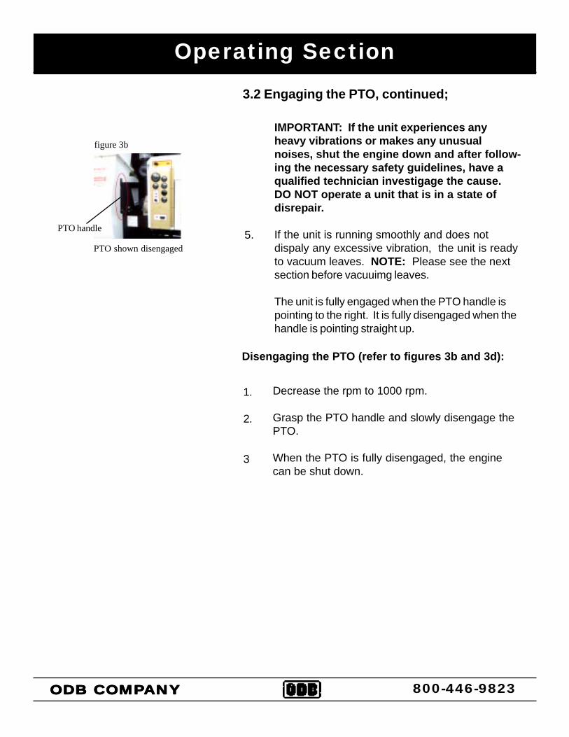
3.2 Engaging the PTO, continued;
IMPORTANT: If the unit experiences anyheavy vibrations or makes any unusualnoises, shut the engine down and after follow-ing the necessary safety guidelines, have aqualified technician investigage the cause.DO NOT operate a unit that is in a state ofdisrepair.
If the unit is running smoothly and does notdispaly any excessive vibration, the unit is readyto vacuum leaves. NOTE: Please see the nextsection before vacuuimg leaves.
The unit is fully engaged when the PTO handle ispointing to the right. It is fully disengaged when thehandle is pointing straight up.
5.
ODB COMPODB COMPODB COMPODB COMPODB COMPANYANYANYANYANY 800-446-9823
Operating Section
Disengaging the PTO (refer to figures 3b and 3d):
Decrease the rpm to 1000 rpm.
Grasp the PTO handle and slowly disengage thePTO.
When the PTO is fully disengaged, the enginecan be shut down.
PTO shown disengaged
figure 3b
PTO handle
1.
2.
3
Operating Section
3.3 Vacuuming Leaves
ODB COMPODB COMPODB COMPODB COMPODB COMPANYANYANYANYANY
Thoroughly read and understand the safety, pre-operating and oper-ating sections of this manual before vacuuming. Wear the propersafety equipment as outlined in this manual.
Start the engine and engage the PTO using the procedures statedearlier in this manual.
Set the engine throttle to around 1200 rpm.
NOTE: Always vacuum leaves using the lowest rpm as possible.This saves fuel and decreases the amount of dust escaping the boxcontainer.
Lower the intake hose to a few inches above the leaf pile. Hold theintake nozzle at a 45 degree angle to allow proper air flow. Thisshould allow the leaves to be vacuumed. DO NOT bury the intakenozzle into the leaf pile, this will cut off the air flow and will makevacuuming much more difficult and increase the chance of clogging.
If the leaves are not vacuuming, increase the rpm to 1400 and tryvacuuming at this setting.
NOTE: Wet leaves will need higher rpm’s to vacuum whereas dryleaves will only need minimal rpm’s.
Continue moving the nozzle in a sweeping motion above the leaveswhile vacuuming.
Vacuuming Leaves:
1.
2.
3.
4.
5.
800-446-9823
Make sure the exhaust hose is connected to the box containerproperly before vacuuming leaves. Visually inspect the leavesbefore vacuuming for any material that could be harmful to the leafvacuum or people. This includes bottles, wood, steel, glass, stoneor other hard or breakable objects.
Read and understand this entire manual before operating, maintain-ing or repairing the leaf vacuum.
4.0 MAINTENANCE SECTION4.1 Maintenance Overview4.2 Maintenance Interval Chart4.3 Lubrication4.4 Preventative Maintenance4.5 Torque Values4.6 Quick Reference Maintenance Chart
4.0MAINTENANCE
SECTION
4.0 MAINTENANCE SECTION
ODB COMPODB COMPODB COMPODB COMPODB COMPANYANYANYANYANY 800-446-9823
Maintenance Section
4.1 MAINTENANCE OVERVIEW:
A properly maintained leaf vacuum will dramatically extend the life of theunit and will create a safer work place as well. For the general safety andwelfare of all personnel it is important to create a scheduled maintenanceprogram that covers all the elements in this manual as well as the engine,PTO and axle owner’s manuals provided with this unit.
Use the chart on the following page as a guide for your scheduled mainte-nance program. If there are any questions concerning any ot these proce-dures please call ODB.
ODB COMPODB COMPODB COMPODB COMPODB COMPANYANYANYANYANY 800-446-9823
Only properly trained personnel should perform maintenance orrepair on this equipment. Consult ODB before performing anymaintenance procedures that is not specificially covered in thismanual. Improper maintenance or repair may void any and all war-ranties on this equipment.
Improper maintenance or repair CAN result in equipment damageand/or personal injuries.
BEFORE CONTINUING, please read and understand the Safety, Pre-operating and Operating sections of this manual before doing anyprodcedures in this section.
80 Hours/2 WeeksItem
Daily/10 hrs
40 Hours/Week
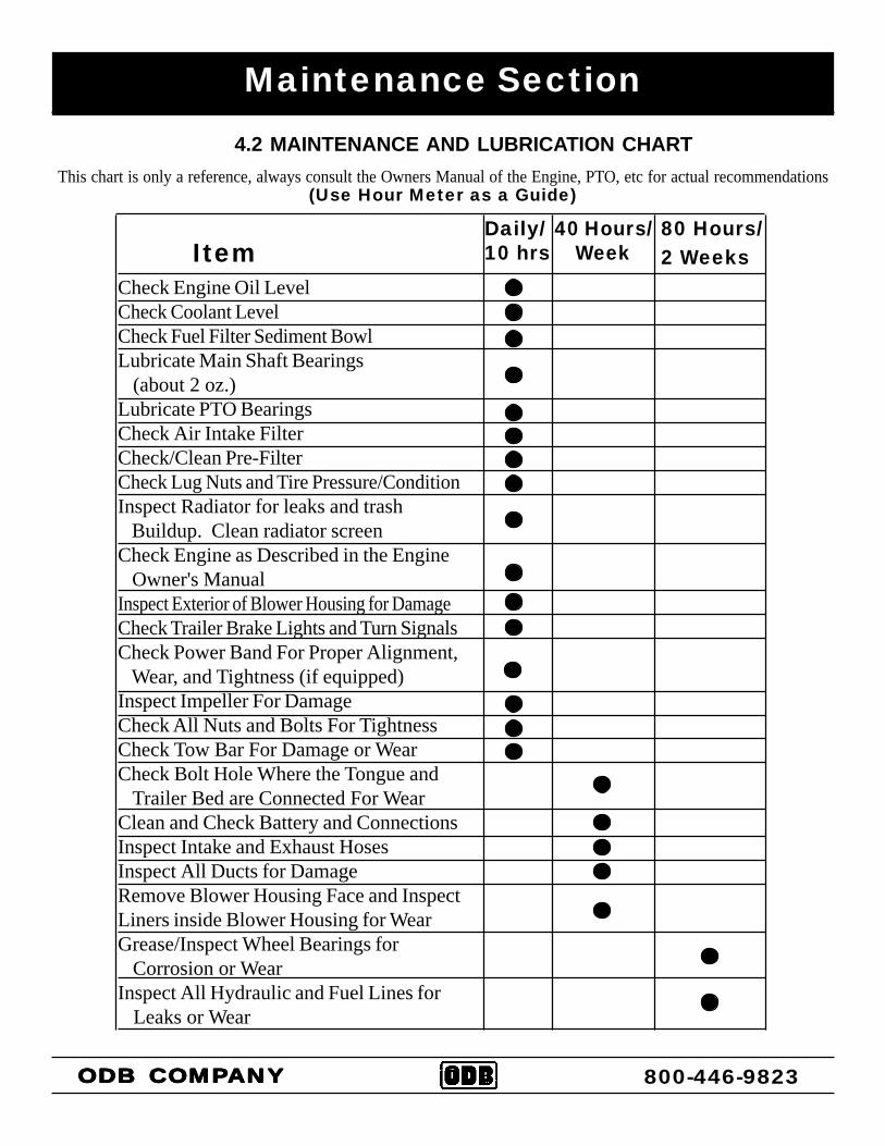
Check Engine Oil LevelCheck Coolant LevelCheck Fuel Filter Sediment BowlLubricate Main Shaft Bearings (about 2 oz.)Lubricate PTO BearingsCheck Air Intake FilterCheck/Clean Pre-FilterCheck Lug Nuts and Tire Pressure/ConditionInspect Radiator for leaks and trash Buildup. Clean radiator screenCheck Engine as Described in the Engine Owner's ManualInspect Exterior of Blower Housing for DamageCheck Trailer Brake Lights and Turn SignalsCheck Power Band For Proper Alignment, Wear, and Tightness (if equipped)Inspect Impeller For DamageCheck All Nuts and Bolts For TightnessCheck Tow Bar For Damage or WearCheck Bolt Hole Where the Tongue and Trailer Bed are Connected For WearClean and Check Battery and ConnectionsInspect Intake and Exhaust HosesInspect All Ducts for DamageRemove Blower Housing Face and InspectLiners inside Blower Housing for WearGrease/Inspect Wheel Bearings for Corrosion or WearInspect All Hydraulic and Fuel Lines for Leaks or Wear
(Use Hour Meter as a Guide)This chart is only a reference, always consult the Owners Manual of the Engine, PTO, etc for actual recommendations
Maintenance Section
ODB COMPODB COMPODB COMPODB COMPODB COMPANYANYANYANYANY 800-446-9823
4.2 MAINTENANCE AND LUBRICATION CHART
Maintenance Section
ODB COMPODB COMPODB COMPODB COMPODB COMPANYANYANYANYANY 800-446-9823
4.3 LUBRICATION:
The following are general lubrication procedures for ourstandard units. Any special or custom built units mayhave other lubrication procedures not directly mentionedin this manual. Please consult ODB before any lubricat-ing procedures not specifically mentioned in this manual.
Proper lubrication of your unit correlates directly to how longyour unit will last. A properly maintained unit will last muchlonger than a unit that is not maintained properly. NOTE:Always lubricate bearings at the end of each work day.This will displace any moisture in the bearings. Also lubri-cate thorougly before extended shutdown or storage.
Remove the negative battery terminal beforeattempting any lubrication procedures.
Thoroughly read and understand the safety andpre-operating sections of this manual before per-forming any lubrication procedures.
Lubrication Points:
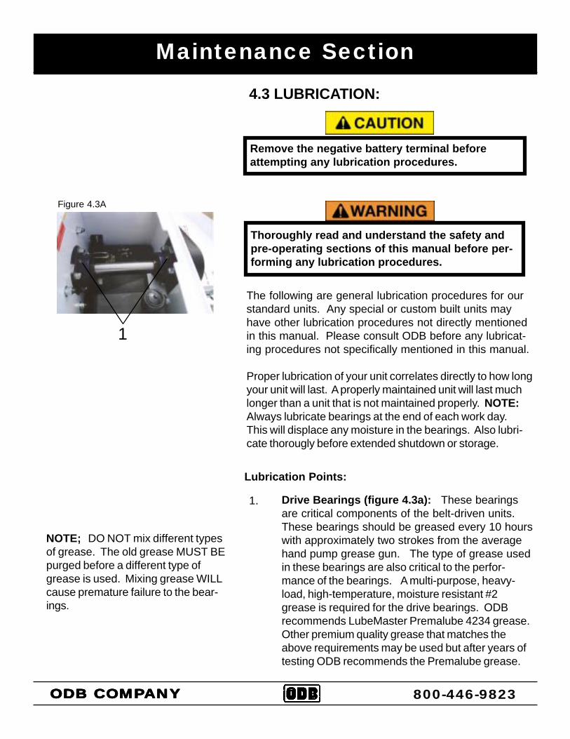
1. Drive Bearings (figure 4.3a): These bearingsare critical components of the belt-driven units.These bearings should be greased every 10 hourswith approximately two strokes from the averagehand pump grease gun. The type of grease usedin these bearings are also critical to the perfor-mance of the bearings. A multi-purpose, heavy-load, high-temperature, moisture resistant #2grease is required for the drive bearings. ODBrecommends LubeMaster Premalube 4234 grease.Other premium quality grease that matches theabove requirements may be used but after years oftesting ODB recommends the Premalube grease.
1
Figure 4.3A
NOTE; DO NOT mix different typesof grease. The old grease MUST BEpurged before a different type ofgrease is used. Mixing grease WILLcause premature failure to the bear-ings.
Lubrication Points, continued;
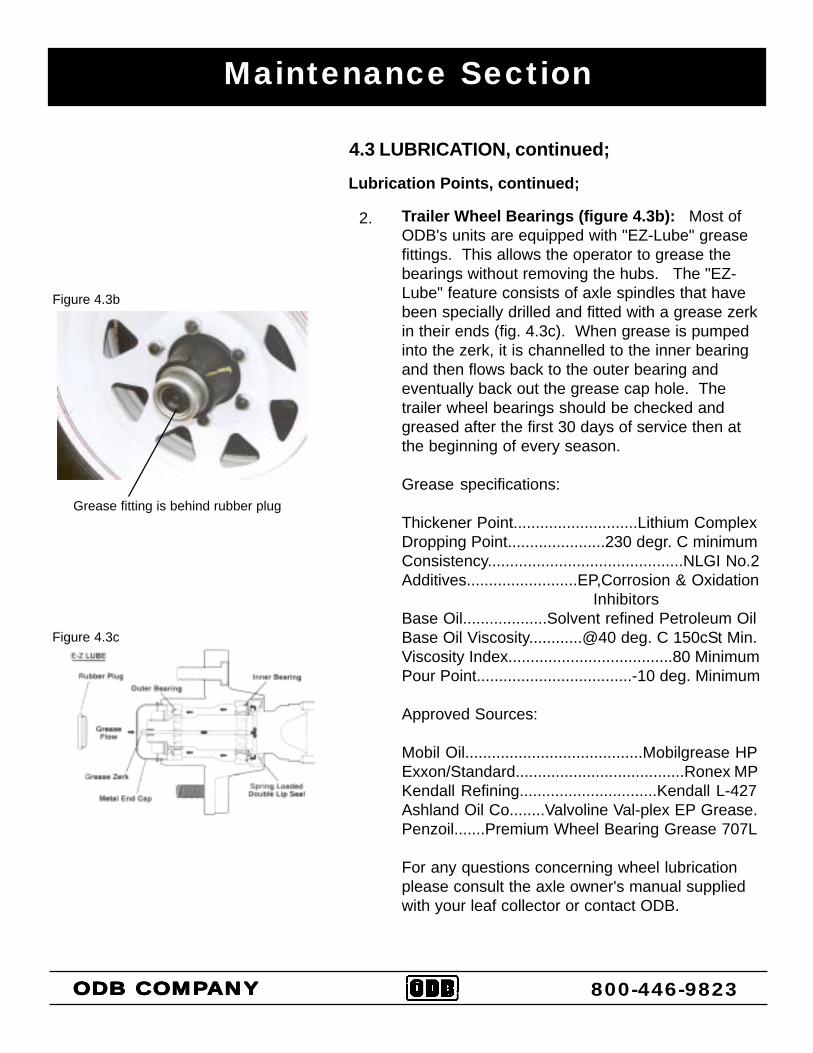
Trailer Wheel Bearings (figure 4.3b): Most ofODB's units are equipped with "EZ-Lube" greasefittings. This allows the operator to grease thebearings without removing the hubs. The "EZ-Lube" feature consists of axle spindles that havebeen specially drilled and fitted with a grease zerkin their ends (fig. 4.3c). When grease is pumpedinto the zerk, it is channelled to the inner bearingand then flows back to the outer bearing andeventually back out the grease cap hole. Thetrailer wheel bearings should be checked andgreased after the first 30 days of service then atthe beginning of every season.
Grease specifications:
Thickener Point............................Lithium ComplexDropping Point......................230 degr. C minimumConsistency............................................NLGI No.2Additives.........................EP,Corrosion & Oxidation
InhibitorsBase Oil...................Solvent refined Petroleum OilBase Oil Viscosity............@40 deg. C 150cSt Min.Viscosity Index.....................................80 MinimumPour Point...................................-10 deg. Minimum
Approved Sources:
Mobil Oil........................................Mobilgrease HPExxon/Standard......................................Ronex MPKendall Refining...............................Kendall L-427Ashland Oil Co........Valvoline Val-plex EP Grease.Penzoil.......Premium Wheel Bearing Grease 707L
For any questions concerning wheel lubricationplease consult the axle owner's manual suppliedwith your leaf collector or contact ODB.
Figure 4.3b
2.
4.3 LUBRICATION, continued;
Grease fitting is behind rubber plug
Figure 4.3c
Maintenance Section
ODB COMPODB COMPODB COMPODB COMPODB COMPANYANYANYANYANY 800-446-9823
Maintenance Section
ODB COMPODB COMPODB COMPODB COMPODB COMPANYANYANYANYANY 800-446-9823
Lubrication Points, continued;
Boom Swivel Bearings (figure 4.3d): Thesebearings are on most of ODB's model LCT600 andLCT6000 after 1996. Grease the boom bearingsonce every week with a multi-purpose moistureresistant #2 grease.
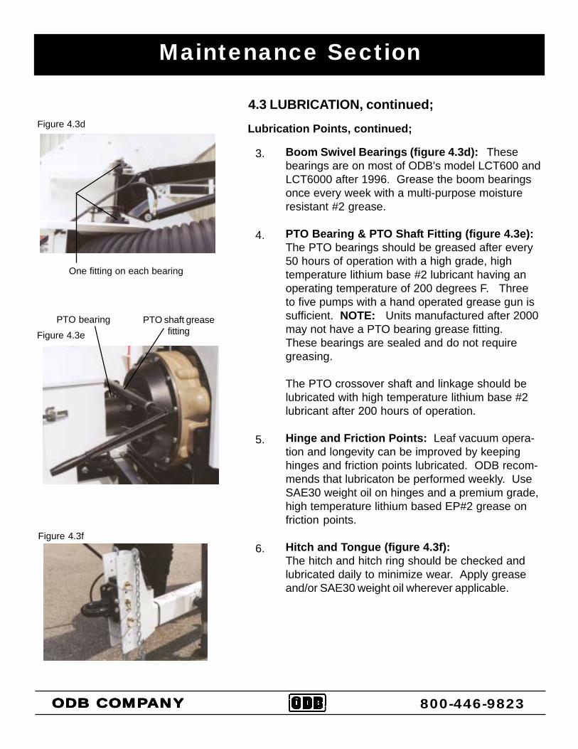
PTO Bearing & PTO Shaft Fitting (figure 4.3e):The PTO bearings should be greased after every50 hours of operation with a high grade, hightemperature lithium base #2 lubricant having anoperating temperature of 200 degrees F. Threeto five pumps with a hand operated grease gun issufficient. NOTE: Units manufactured after 2000may not have a PTO bearing grease fitting.These bearings are sealed and do not requiregreasing.
The PTO crossover shaft and linkage should belubricated with high temperature lithium base #2lubricant after 200 hours of operation.
Hinge and Friction Points: Leaf vacuum opera-tion and longevity can be improved by keepinghinges and friction points lubricated. ODB recom-mends that lubricaton be performed weekly. UseSAE30 weight oil on hinges and a premium grade,high temperature lithium based EP#2 grease onfriction points.
Hitch and Tongue (figure 4.3f):The hitch and hitch ring should be checked andlubricated daily to minimize wear. Apply greaseand/or SAE30 weight oil wherever applicable.
Figure 4.3d
3.
4.
5.
6.
4.3 LUBRICATION, continued;
One fitting on each bearing
Figure 4.3ePTO bearing PTO shaft grease
fitting
Figure 4.3f
Maintenance Section
ODB COMPODB COMPODB COMPODB COMPODB COMPANYANYANYANYANY 800-446-9823
4.4 PREVENTATIVE MAINTENANCE
The following are general preventative maintenance procedures for our stan-dard units. Any special or custom built units may have other preventativemaintenance procedures not directly mentioned in this manual. Please con-sult ODB before doing any preventative maintenance procedures not specifi-cally mentioned in this manual.
Proper preventative maintenance of your unit, just like lubrication, correlatesdirectly to how long your unit will last. A properly maintained unit will lastmuch longer than a unit that is not maintained properly.
Remove the negative battery terminal before attempting any mainte-nance procedures.
Thoroughly read and understand the safety and pre-operating sec-tions of this manual before performing any maintenance procedures.
Preventative Maintenance:
1.
2.
Engine Oil: Change the oil and oil filter according to schedules pro-vided in your engine's owner's manual (EOM). The engine oil levelshould be checked every day. The level should be checked after theengine has been stopped for a period of time. This will allow the oil todrain back into the oil pan, allowing a better indication of the true oillevel. If the level is low, see the engines owner's manual for the correcttype of oil.
Engine Coolant: Check the coolant level before starting the unit eachday. The coolant level should not be less than one inch below the topof the radiator.
NEVER check the engine coolant when the engine is hot. Allow theengine to cool at least one hour before checking the coolant. Checkthe engine owner's manual for instructions. ALWAYS wear eye andhand protection when working with the radiator.
Maintenance Section
ODB COMPODB COMPODB COMPODB COMPODB COMPANYANYANYANYANY 800-446-9823
4.4 PREVENTATIVE MAINTENANCE, continued;Preventative Maintenance, continued;
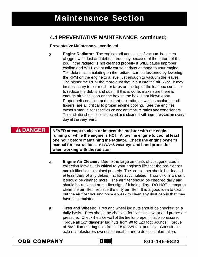
Engine Radiator: The engine radiator on a leaf vacuum becomesclogged with dust and debris frequently because of the nature of thejob. If the radiator is not cleaned properly it WILL cause impropercooling and WILL eventually cause serious damage to your engine.The debris accumulating on the radiator can be lessened by loweringthe RPM on the engine to a level just enough to vacuum the leaves.The higher the RPM the more dust that is put into the air. Also, it maybe necessary to put mesh or tarps on the top of the leaf box containerto reduce the debris and dust. If this is done, make sure there isenough air ventilation on the box so the box is not blown apart.Proper belt condition and coolant mix-ratio, as well as coolant condi-tioners, are all critical to proper engine cooling. See the enginesowner's manual for specifics on coolant mixture ratios and conditioners.The radiator should be inspected and cleaned with compressed air every-day at the very least.
Engine Air Cleaner: Due to the large amounts of dust generated incollection leaves, it is critical to your engine's life that the pre-cleanerand air filter be maintained properly. The pre-cleaner should be cleanedat least daily of any debris that has accumulated. If conditions warrantit should be cleaned more. The air filter should be checked daily andshould be replaced at the first sign of it being dirty. DO NOT attempt toclean the air filter, replace the dirty air filter. It is a good idea to cleanout the air filter housing once a week to clean any dust debris that mayhave accumulated.
Tires and Wheels: Tires and wheel lug nuts should be checked on adaily basis. Tires should be checked for excessive wear and proper airpressure. Check the side wall of the tire for proper inflation pressure.Torque all 1/2" diameter lug nuts from 90 to 120 foot pounds. Torqueall 5/8" diameter lug nuts from 175 to 225 foot pounds. Consult theaxle manufacturers owner's manual for more detailed information.
NEVER attempt to clean or inspect the radiator with the enginerunning or while the engine is HOT. Allow the engine to cool at leastone hour before mantaining the radiator. Check the engine owner'smanual for instructions. ALWAYS wear eye and hand protectionwhen working with the radiator.
3.
4.
5.
Maintenance Section
ODB COMPODB COMPODB COMPODB COMPODB COMPANYANYANYANYANY 800-446-9823
4.4 PREVENTATIVE MAINTENANCE, continued;Preventative Maintenance, continued;
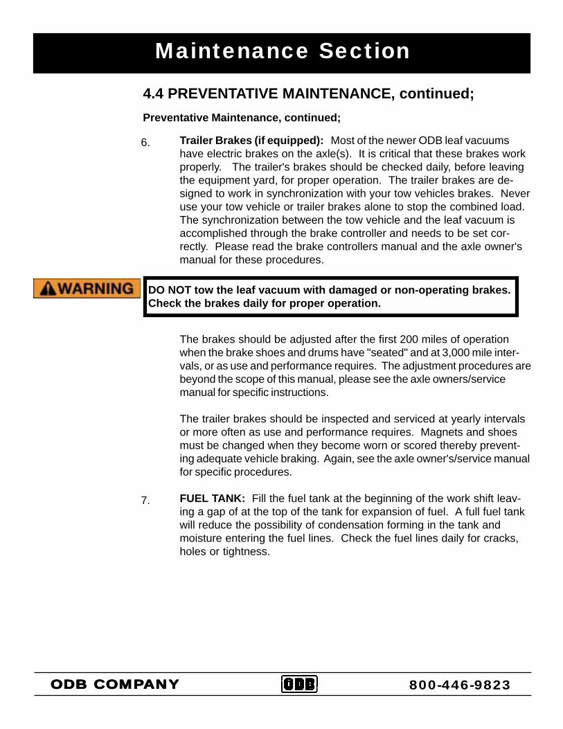
Trailer Brakes (if equipped): Most of the newer ODB leaf vacuumshave electric brakes on the axle(s). It is critical that these brakes workproperly. The trailer's brakes should be checked daily, before leavingthe equipment yard, for proper operation. The trailer brakes are de-signed to work in synchronization with your tow vehicles brakes. Neveruse your tow vehicle or trailer brakes alone to stop the combined load.The synchronization between the tow vehicle and the leaf vacuum isaccomplished through the brake controller and needs to be set cor-rectly. Please read the brake controllers manual and the axle owner'smanual for these procedures.
The brakes should be adjusted after the first 200 miles of operationwhen the brake shoes and drums have "seated" and at 3,000 mile inter-vals, or as use and performance requires. The adjustment procedures arebeyond the scope of this manual, please see the axle owners/servicemanual for specific instructions.
The trailer brakes should be inspected and serviced at yearly intervalsor more often as use and performance requires. Magnets and shoesmust be changed when they become worn or scored thereby prevent-ing adequate vehicle braking. Again, see the axle owner's/service manualfor specific procedures.
FUEL TANK: Fill the fuel tank at the beginning of the work shift leav-ing a gap of at the top of the tank for expansion of fuel. A full fuel tankwill reduce the possibility of condensation forming in the tank andmoisture entering the fuel lines. Check the fuel lines daily for cracks,holes or tightness.
6.
7.
DO NOT tow the leaf vacuum with damaged or non-operating brakes.Check the brakes daily for proper operation.
Maintenance Section
ODB COMPODB COMPODB COMPODB COMPODB COMPANYANYANYANYANY 800-446-9823
4.4 PREVENTATIVE MAINTENANCE, continued;Preventative Maintenance, continued;
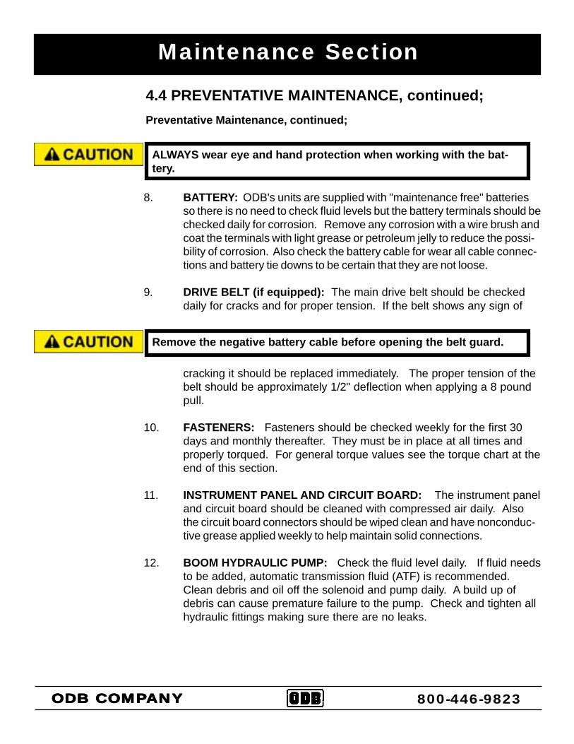
BATTERY: ODB's units are supplied with "maintenance free" batteriesso there is no need to check fluid levels but the battery terminals should bechecked daily for corrosion. Remove any corrosion with a wire brush andcoat the terminals with light grease or petroleum jelly to reduce the possi-bility of corrosion. Also check the battery cable for wear all cable connec-tions and battery tie downs to be certain that they are not loose.
DRIVE BELT (if equipped): The main drive belt should be checkeddaily for cracks and for proper tension. If the belt shows any sign of
cracking it should be replaced immediately. The proper tension of thebelt should be approximately 1/2" deflection when applying a 8 poundpull.
FASTENERS: Fasteners should be checked weekly for the first 30days and monthly thereafter. They must be in place at all times andproperly torqued. For general torque values see the torque chart at theend of this section.
INSTRUMENT PANEL AND CIRCUIT BOARD: The instrument paneland circuit board should be cleaned with compressed air daily. Alsothe circuit board connectors should be wiped clean and have nonconduc-tive grease applied weekly to help maintain solid connections.
BOOM HYDRAULIC PUMP: Check the fluid level daily. If fluid needsto be added, automatic transmission fluid (ATF) is recommended.Clean debris and oil off the solenoid and pump daily. A build up ofdebris can cause premature failure to the pump. Check and tighten allhydraulic fittings making sure there are no leaks.
8.
9.
10.
11.
12.
ALWAYS wear eye and hand protection when working with the bat-tery.
Remove the negative battery cable before opening the belt guard.
Maintenance Section
ODB COMPODB COMPODB COMPODB COMPODB COMPANYANYANYANYANY 800-446-9823
4.5 TORQUE VALUES
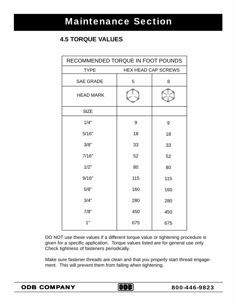
RECOMMENDED TORQUE IN FOOT POUNDS
TYPE
SAE GRADE
HEX HEAD CAP SCREWS
5 8
SIZE
1/4"
5/16"
3/8"
7/16"
1/2"
9/16"
5/8"
3/4"
7/8"
1"
9
18
33
52
80
115
160
280
450
675
9
18
33
52
80
115
160
280
450
675
HEAD MARK
DO NOT use these values if a different torque value or tightening procedure isgiven for a specific application. Torque values listed are for general use only.Check tightness of fasteners periodically.
Make sure fastener threads are clean and that you properly start thread engage-ment. This will prevent them from failing when tightening.
4.6 QUICK REFERENCE MAINTENANCE CHART:
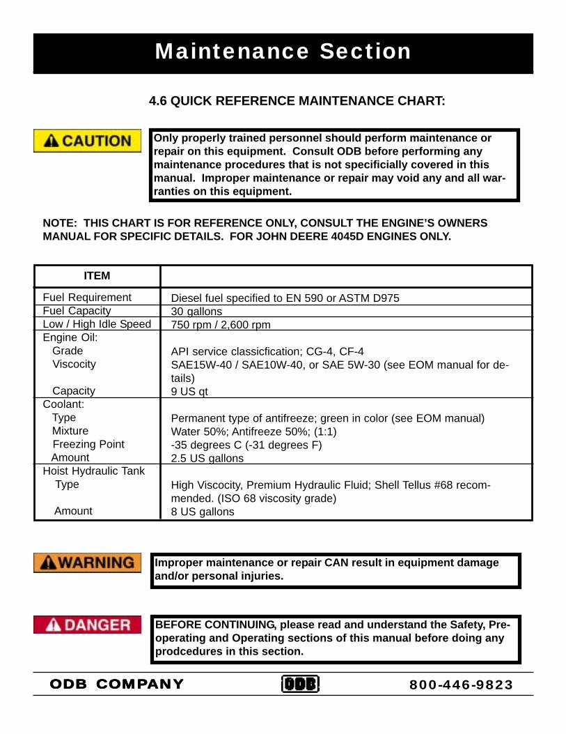
Only properly trained personnel should perform maintenance orrepair on this equipment. Consult ODB before performing anymaintenance procedures that is not specificially covered in thismanual. Improper maintenance or repair may void any and all war-ranties on this equipment.
Improper maintenance or repair CAN result in equipment damageand/or personal injuries.
BEFORE CONTINUING, please read and understand the Safety, Pre-operating and Operating sections of this manual before doing anyprodcedures in this section.
ITEM
Fuel RequirementFuel CapacityLow / High Idle SpeedEngine Oil: Grade Viscocity
CapacityCoolant: Type Mixture Freezing Point AmountHoist Hydraulic Tank Type
Amount
Diesel fuel specified to EN 590 or ASTM D97530 gallons750 rpm / 2,600 rpm
API service classicfication; CG-4, CF-4SAE15W-40 / SAE10W-40, or SAE 5W-30 (see EOM manual for de-tails)9 US qt
Permanent type of antifreeze; green in color (see EOM manual)Water 50%; Antifreeze 50%; (1:1)-35 degrees C (-31 degrees F)2.5 US gallons
High Viscocity, Premium Hydraulic Fluid; Shell Tellus #68 recom-mended. (ISO 68 viscosity grade)8 US gallons
NOTE: THIS CHART IS FOR REFERENCE ONLY, CONSULT THE ENGINE’S OWNERSMANUAL FOR SPECIFIC DETAILS. FOR JOHN DEERE 4045D ENGINES ONLY.
Maintenance Section
ODB COMPODB COMPODB COMPODB COMPODB COMPANYANYANYANYANY 800-446-9823
THETHETHETHETHE
SERVICE SECTIONService and TroubleshootingWiring Diagrams
SE
RV
ICE
SE
CT
ION
800-446-9823
ODB COMPODB COMPODB COMPODB COMPODB COMPANYANYANYANYANY5118 Glen Alden DriveRichmond, VA 23231
THETHETHETHETHE
SERVICE AND TROUBLESHOOTING*Service and Repair*Engine Electrical Troubleshooting*Circuit Board Troubleshooting*Auto PTO Adjustment Guide*Hydraulic Boom Troubleshooting*Impeller Installation*Belt Adjustment and Replacement Guide
SE
RV
ICE
AN
D T
RO
UB
LE S
HO
OT
ING
800-446-9823
ODB COMPODB COMPODB COMPODB COMPODB COMPANYANYANYANYANY5118 Glen Alden DriveRichmond, VA 23231
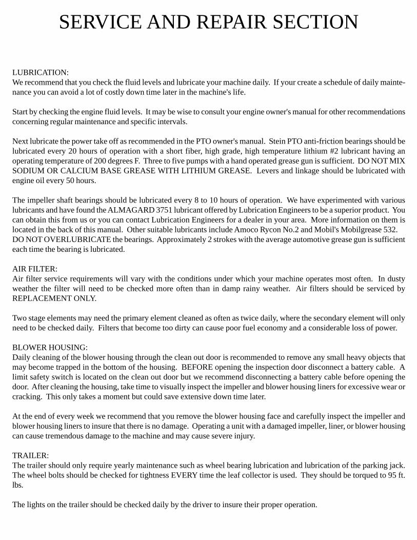
LUBRICATION:We recommend that you check the fluid levels and lubricate your machine daily. If your create a schedule of daily mainte-nance you can avoid a lot of costly down time later in the machine's life.
Start by checking the engine fluid levels. It may be wise to consult your engine owner's manual for other recommendationsconcerning regular maintenance and specific intervals.
Next lubricate the power take off as recommended in the PTO owner's manual. Stein PTO anti-friction bearings should belubricated every 20 hours of operation with a short fiber, high grade, high temperature lithium #2 lubricant having anoperating temperature of 200 degrees F. Three to five pumps with a hand operated grease gun is sufficient. DO NOT MIXSODIUM OR CALCIUM BASE GREASE WITH LITHIUM GREASE. Levers and linkage should be lubricated withengine oil every 50 hours.
The impeller shaft bearings should be lubricated every 8 to 10 hours of operation. We have experimented with variouslubricants and have found the ALMAGARD 3751 lubricant offered by Lubrication Engineers to be a superior product. Youcan obtain this from us or you can contact Lubrication Engineers for a dealer in your area. More information on them islocated in the back of this manual. Other suitable lubricants include Amoco Rycon No.2 and Mobil's Mobilgrease 532.DO NOT OVERLUBRICATE the bearings. Approximately 2 strokes with the average automotive grease gun is sufficienteach time the bearing is lubricated.
AIR FILTER:Air filter service requirements will vary with the conditions under which your machine operates most often. In dustyweather the filter will need to be checked more often than in damp rainy weather. Air filters should be serviced byREPLACEMENT ONLY.
Two stage elements may need the primary element cleaned as often as twice daily, where the secondary element will onlyneed to be checked daily. Filters that become too dirty can cause poor fuel economy and a considerable loss of power.
BLOWER HOUSING:Daily cleaning of the blower housing through the clean out door is recommended to remove any small heavy objects thatmay become trapped in the bottom of the housing. BEFORE opening the inspection door disconnect a battery cable. Alimit safety switch is located on the clean out door but we recommend disconnecting a battery cable before opening thedoor. After cleaning the housing, take time to visually inspect the impeller and blower housing liners for excessive wear orcracking. This only takes a moment but could save extensive down time later.
At the end of every week we recommend that you remove the blower housing face and carefully inspect the impeller andblower housing liners to insure that there is no damage. Operating a unit with a damaged impeller, liner, or blower housingcan cause tremendous damage to the machine and may cause severe injury.
TRAILER:The trailer should only require yearly maintenance such as wheel bearing lubrication and lubrication of the parking jack.The wheel bolts should be checked for tightness EVERY time the leaf collector is used. They should be torqued to 95 ft.lbs.
The lights on the trailer should be checked daily by the driver to insure their proper operation.
SERVICE AND REPAIR SECTION
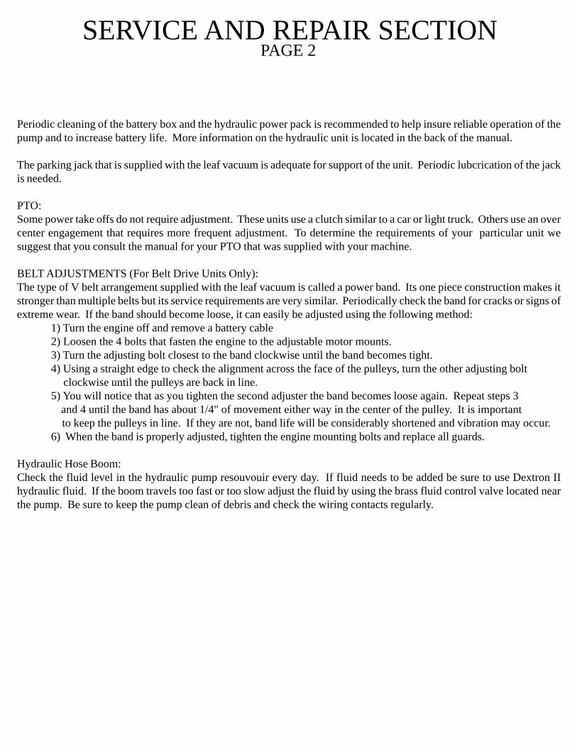
Periodic cleaning of the battery box and the hydraulic power pack is recommended to help insure reliable operation of thepump and to increase battery life. More information on the hydraulic unit is located in the back of the manual.
The parking jack that is supplied with the leaf vacuum is adequate for support of the unit. Periodic lubcrication of the jackis needed.
PTO:Some power take offs do not require adjustment. These units use a clutch similar to a car or light truck. Others use an overcenter engagement that requires more frequent adjustment. To determine the requirements of your particular unit wesuggest that you consult the manual for your PTO that was supplied with your machine.
BELT ADJUSTMENTS (For Belt Drive Units Only):The type of V belt arrangement supplied with the leaf vacuum is called a power band. Its one piece construction makes itstronger than multiple belts but its service requirements are very similar. Periodically check the band for cracks or signs ofextreme wear. If the band should become loose, it can easily be adjusted using the following method:
1) Turn the engine off and remove a battery cable2) Loosen the 4 bolts that fasten the engine to the adjustable motor mounts.3) Turn the adjusting bolt closest to the band clockwise until the band becomes tight.4) Using a straight edge to check the alignment across the face of the pulleys, turn the other adjusting bolt clockwise until the pulleys are back in line.5) You will notice that as you tighten the second adjuster the band becomes loose again. Repeat steps 3
and 4 until the band has about 1/4" of movement either way in the center of the pulley. It is important to keep the pulleys in line. If they are not, band life will be considerably shortened and vibration may occur.
6) When the band is properly adjusted, tighten the engine mounting bolts and replace all guards.
Hydraulic Hose Boom:Check the fluid level in the hydraulic pump resouvouir every day. If fluid needs to be added be sure to use Dextron IIhydraulic fluid. If the boom travels too fast or too slow adjust the fluid by using the brass fluid control valve located nearthe pump. Be sure to keep the pump clean of debris and check the wiring contacts regularly.
SERVICE AND REPAIR SECTIONPAGE 2
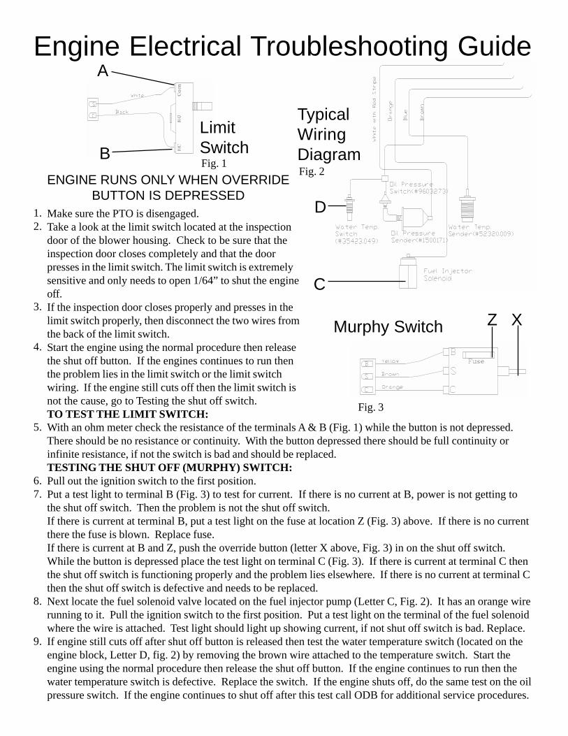
Engine Electrical Troubleshooting Guide
Z X
Make sure the PTO is disengaged.Take a look at the limit switch located at the inspectiondoor of the blower housing. Check to be sure that theinspection door closes completely and that the doorpresses in the limit switch. The limit switch is extremelysensitive and only needs to open 1/64” to shut the engineoff.If the inspection door closes properly and presses in thelimit switch properly, then disconnect the two wires fromthe back of the limit switch.Start the engine using the normal procedure then releasethe shut off button. If the engines continues to run thenthe problem lies in the limit switch or the limit switchwiring. If the engine still cuts off then the limit switch isnot the cause, go to Testing the shut off switch.TO TEST THE LIMIT SWITCH:
Murphy Switch
ENGINE RUNS ONLY WHEN OVERRIDEBUTTON IS DEPRESSED
1.2.
3.
4.
5.
6.7.
8.
9.
TypicalWiringDiagram
Fig. 3
Fig. 2
A
B
With an ohm meter check the resistance of the terminals A & B (Fig. 1) while the button is not depressed.There should be no resistance or continuity. With the button depressed there should be full continuity orinfinite resistance, if not the switch is bad and should be replaced.TESTING THE SHUT OFF (MURPHY) SWITCH:Pull out the ignition switch to the first position.Put a test light to terminal B (Fig. 3) to test for current. If there is no current at B, power is not getting tothe shut off switch. Then the problem is not the shut off switch.If there is current at terminal B, put a test light on the fuse at location Z (Fig. 3) above. If there is no currentthere the fuse is blown. Replace fuse.If there is current at B and Z, push the override button (letter X above, Fig. 3) in on the shut off switch.While the button is depressed place the test light on terminal C (Fig. 3). If there is current at terminal C thenthe shut off switch is functioning properly and the problem lies elsewhere. If there is no current at terminal Cthen the shut off switch is defective and needs to be replaced.Next locate the fuel solenoid valve located on the fuel injector pump (Letter C, Fig. 2). It has an orange wirerunning to it. Pull the ignition switch to the first position. Put a test light on the terminal of the fuel solenoidwhere the wire is attached. Test light should light up showing current, if not shut off switch is bad. Replace.If engine still cuts off after shut off button is released then test the water temperature switch (located on theengine block, Letter D, fig. 2) by removing the brown wire attached to the temperature switch. Start theengine using the normal procedure then release the shut off button. If the engine continues to run then thewater temperature switch is defective. Replace the switch. If the engine shuts off, do the same test on the oilpressure switch. If the engine continues to shut off after this test call ODB for additional service procedures.
C
D
LimitSwitchFig. 1
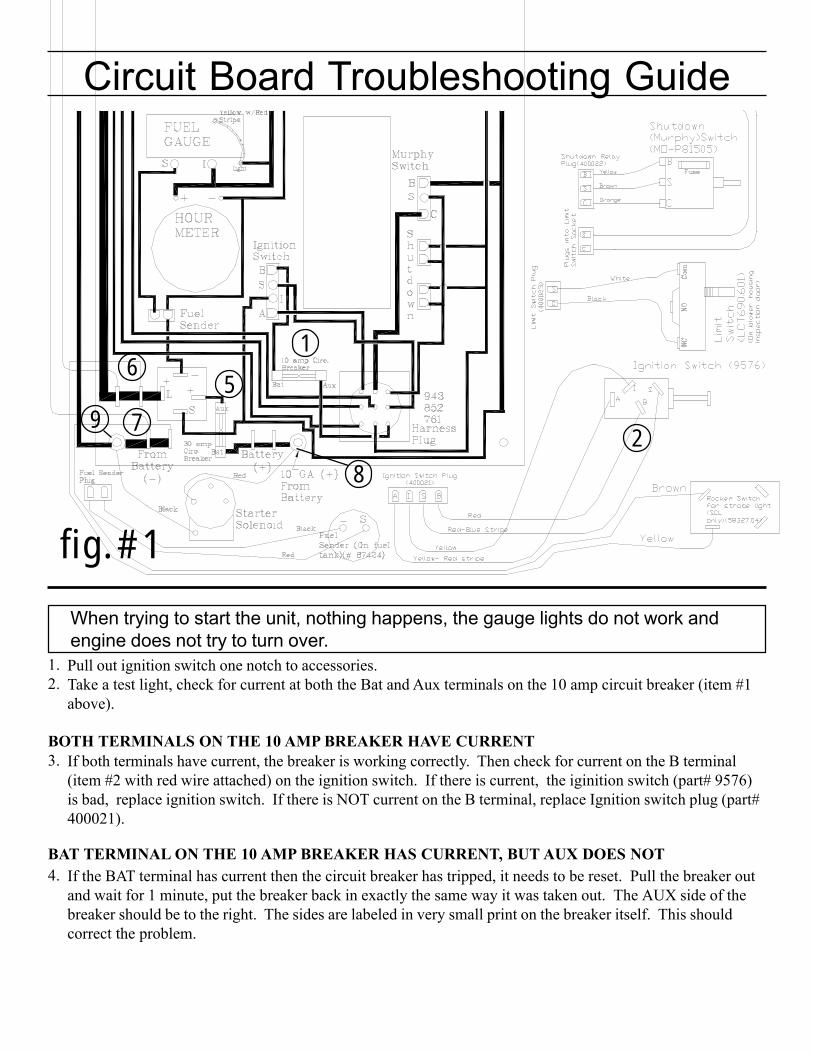
Circuit Board Troubleshooting Guide
Pull out ignition switch one notch to accessories.Take a test light, check for current at both the Bat and Aux terminals on the 10 amp circuit breaker (item #1above).
If both terminals have current, the breaker is working correctly. Then check for current on the B terminal(item #2 with red wire attached) on the ignition switch. If there is current, the iginition switch (part# 9576)is bad, replace ignition switch. If there is NOT current on the B terminal, replace Ignition switch plug (part#400021).
If the BAT terminal has current then the circuit breaker has tripped, it needs to be reset. Pull the breaker outand wait for 1 minute, put the breaker back in exactly the same way it was taken out. The AUX side of thebreaker should be to the right. The sides are labeled in very small print on the breaker itself. This shouldcorrect the problem.
When trying to start the unit, nothing happens, the gauge lights do not work andengine does not try to turn over.
1.2.
3.
4.
1
56
2
BOTH TERMINALS ON THE 10 AMP BREAKER HAVE CURRENT
BAT TERMINAL ON THE 10 AMP BREAKER HAS CURRENT, BUT AUX DOES NOT
fig. #1
7
8
9
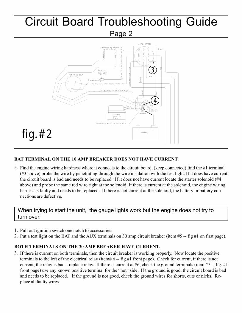
Find the engine wiring hardness where it connects to the circuit board, (keep connected) find the #1 terminal(#3 above) probe the wire by penetrating through the wire insulation with the test light. If it does have currentthe circuit board is bad and needs to be replaced. If it does not have current locate the starter solenoid (#4above) and probe the same red wire right at the solenoid. If there is current at the solenoid, the engine wiringharness is faulty and needs to be replaced. If there is not current at the solenoid, the battery or battery con-nections are defective.
Pull out ignition switch one notch to accessories.Put a test light on the BAT and the AUX terminals on 30 amp circuit breaker (item #5 -- fig #1 on first page).
If there is current on both terminals, then the circuit breaker is working properly. Now locate the positiveterminals to the left of the electrical relay (item# 6 -- fig.#1 front page). Check for current, if there is notcurrent, the relay is bad-- replace relay. If there is current at #6, check the ground terminals (item #7 -- fig. #1front page) use any known positive terminal for the “hot” side. If the ground is good, the circuit board is badand needs to be replaced. If the ground is not good, check the ground wires for shorts, cuts or nicks. Re-place all faulty wires.
5.
1.2.
3.
BAT TERMINAL ON THE 10 AMP BREAKER DOES NOT HAVE CURRENT.
BOTH TERMINALS ON THE 30 AMP BREAKER HAVE CURRENT.
Circuit Board Troubleshooting GuidePage 2
3
4
When trying to start the unit, the gauge lights work but the engine does not try toturn over.
fig. #2
If the BAT terminal has current, then the circuit breaker has tripped, it needs to be reset. Pull the breaker outand wait for 1 minute, put the breaker back in exactly the same way it was taken out. The AUX side of thebreaker should be at the top. The sides are labeled in very small print on the breaker itself. This shouldcorrect the problem.
If there is no current at either terminal of the 30 amp breaker then check the 10 gauge Red wire (item #8-- fig.1, first page) for current. If there is current at this terminal, check the 10 gauge Black wire (item #9 -- fig. 1,first page) ground cable to make sure the board is properly grounded. Replace or tighten any shorted orloose wires. If there is no current at Red 10 gauge wire terminal (Item #8) then trace the red wire back to thestarter solenoid and check for current there. If there is no current there check the battery and the batterycables for any possible shorts.
IF THESE PROCEDURES DO NOT ISOLATE YOUR PROBLEM PLEASE CALL ODB AT800-446-9823 SO THAT WE MAY ASSIST YOU.
4.
5.
BAT TERMINAL ON THE 30 AMP BREAKER HAS CURRENT, BUT AUX DOES NOT.
BOTH TERMINALS ON THE 30 AMP BREAKER DO NOT HAVE CURRENT.
Circuit Board Troubleshooting GuidePage 3
A
C
B
D
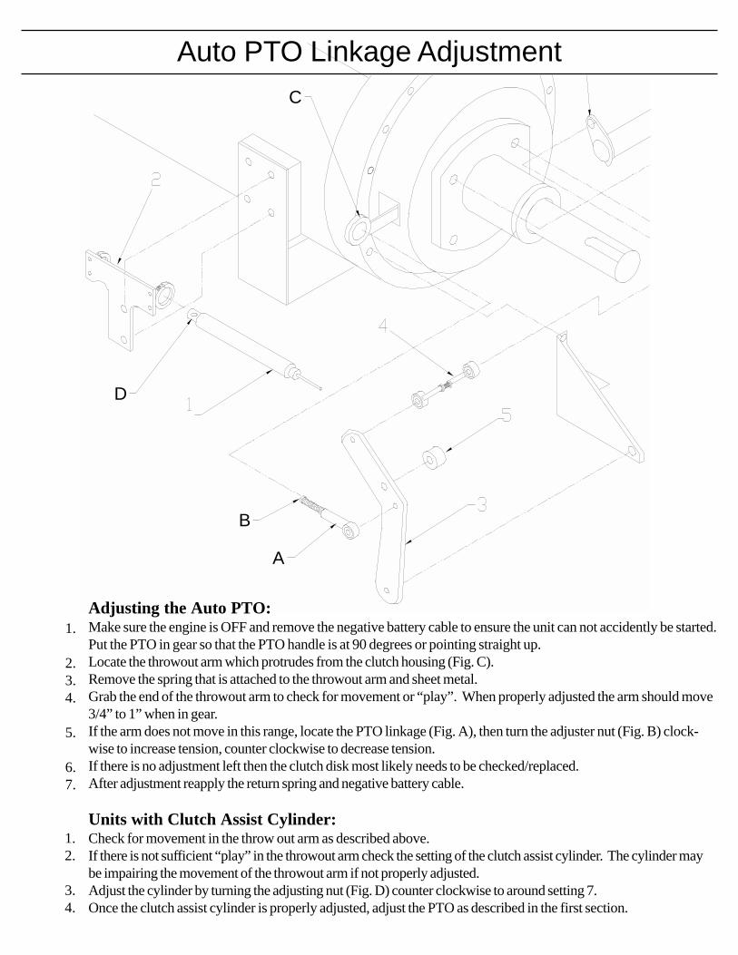
Auto PTO Linkage Adjustment
Adjusting the Auto PTO:Make sure the engine is OFF and remove the negative battery cable to ensure the unit can not accidently be started.Put the PTO in gear so that the PTO handle is at 90 degrees or pointing straight up.Locate the throwout arm which protrudes from the clutch housing (Fig. C).Remove the spring that is attached to the throwout arm and sheet metal.Grab the end of the throwout arm to check for movement or “play”. When properly adjusted the arm should move3/4” to 1” when in gear.If the arm does not move in this range, locate the PTO linkage (Fig. A), then turn the adjuster nut (Fig. B) clock-wise to increase tension, counter clockwise to decrease tension.If there is no adjustment left then the clutch disk most likely needs to be checked/replaced.After adjustment reapply the return spring and negative battery cable.
Units with Clutch Assist Cylinder:Check for movement in the throw out arm as described above.If there is not sufficient “play” in the throwout arm check the setting of the clutch assist cylinder. The cylinder maybe impairing the movement of the throwout arm if not properly adjusted.Adjust the cylinder by turning the adjusting nut (Fig. D) counter clockwise to around setting 7.Once the clutch assist cylinder is properly adjusted, adjust the PTO as described in the first section.
1.
2.3.4.
5.
6.7.
1.2.
3.4.
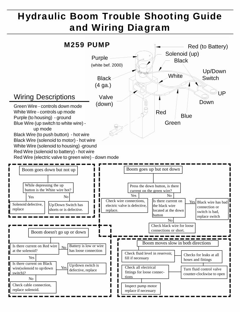
Hydraulic Boom Trouble Shooting Guideand Wiring Diagram
Boom goes down but not up
While depressing the upbutton is the White wire hot?
Solenoid defective,replace
Yes
Up/Down Switch hasshorts or is defective.
No
Boom goes up but not down
Press the down button, is therecurrent on the green wire?
Check black wire for looseconnections or short.
Check wire connections,electric valve is defective,replace.
Yes No
Black wire has badconnection orswitch is bad,replace switch
No
Is there current onthe black wirelocated at the downbutton
Boom doesn't go up or down
Is there current on Red wireat the solenoid?
Is there current on Blackwire(solenoid to up/downswitch)?
Check cable connection,replace solenoid.
Battery is low or wirehas loose connection
Up/down switch isdefective, replace
No
No
Yes
Yes
Boom moves slow in both directions
Check fluid level in reservoir,fill if necessary
Inspect pump motorreplace if necessary
Check all electricalfittings for loose connec-tions
Checks for leaks at allhoses and fittings
Turn fluid control valvecounter-clockwise to open
Yes
Black(4 ga.)
Up/Down Switch
UPDown
Black
BlueGreen
Red
White
Purple(white bef. 2000)
Valve(down)
Solenoid (up)Red (to Battery)M259 PUMP
Green Wire - controls down modeWhite Wire - controls up modePurple (to housing) - groundBlue Wire (up switch to white wire) - up modeBlack Wire (to push button) - hot wireBlack Wire (solenoid to motor) - hot wireWhite Wire (solenoid to housing) -groundRed Wire (solenoid to battery) - hot wireRed Wire (electric valve to green wire) - down mode
Wiring Descriptions
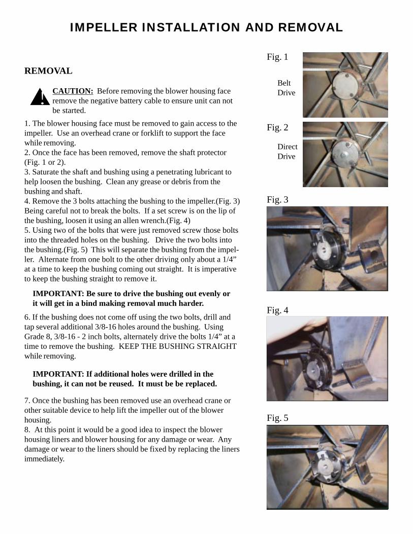
IMPELLER INSTALLATION AND REMOVAL
REMOVAL
1. The blower housing face must be removed to gain access to theimpeller. Use an overhead crane or forklift to support the facewhile removing.2. Once the face has been removed, remove the shaft protector(Fig. 1 or 2).3. Saturate the shaft and bushing using a penetrating lubricant tohelp loosen the bushing. Clean any grease or debris from thebushing and shaft.4. Remove the 3 bolts attaching the bushing to the impeller.(Fig. 3)Being careful not to break the bolts. If a set screw is on the lip ofthe bushing, loosen it using an allen wrench.(Fig. 4)5. Using two of the bolts that were just removed screw those boltsinto the threaded holes on the bushing. Drive the two bolts intothe bushing.(Fig. 5) This will separate the bushing from the impel-ler. Alternate from one bolt to the other driving only about a 1/4”at a time to keep the bushing coming out straight. It is imperativeto keep the bushing straight to remove it.
Fig. 3
Fig. 4
Fig. 5
6. If the bushing does not come off using the two bolts, drill andtap several additional 3/8-16 holes around the bushing. UsingGrade 8, 3/8-16 - 2 inch bolts, alternately drive the bolts 1/4” at atime to remove the bushing. KEEP THE BUSHING STRAIGHTwhile removing.
IMPORTANT: Be sure to drive the bushing out evenly orit will get in a bind making removal much harder.
7. Once the bushing has been removed use an overhead crane orother suitable device to help lift the impeller out of the blowerhousing.8. At this point it would be a good idea to inspect the blowerhousing liners and blower housing for any damage or wear. Anydamage or wear to the liners should be fixed by replacing the linersimmediately.
IMPORTANT: If additional holes were drilled in thebushing, it can not be reused. It must be be replaced.
CAUTION: Before removing the blower housing faceremove the negative battery cable to ensure unit can notbe started.
!
Fig. 1
Fig. 2
BeltDrive
DirectDrive
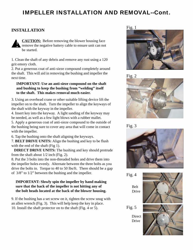
IMPELLER INSTALLATION AND REMOVAL--Cont.
6. Tap the bushing onto the shaft aligning the keyways.7. BELT DRIVE UNITS: Align the bushing and key to be flushwith the end of the shaft (Fig 1). DIRECT DRIVE UNITS: The bushing and key should protrudefrom the shaft about 1/2 inch (Fig. 2).8. Put the 3 bolts into the non-threaded holes and drive them intothe impeller holes evenly. Alternate between the three bolts as youdrive the bolts in. Torque to 40 to 50 lbs/ft. There should be a gapof 3/8” to 1/2” between the bushing and the impeller.
1. Clean the shaft of any debris and remove any rust using a 120grit emory cloth.2. Put a generous coat of anti-sieze compound completely aroundthe shaft. This will aid in removing the bushing and impeller thenext time.
INSTALLATION
CAUTION: Before removing the blower housing faceremove the negative battery cable to ensure unit can notbe started.
!
3. Using an overhead crane or other suitable lifting device lift theimpeller on to the shaft. Turn the impeller to align the keyways ofthe shaft with the keyway in the impeller.4. Insert key into the keyway. A light sanding of the keyway maybe needed, as well as a few light blows with a rubber mallet.5. Apply a generous coat of anti-sieze compound to the outside ofthe bushing being sure to cover any area that will come in contactwith the impeller.
IMPORTANT: Use an anti-sieze compound on the shaftand bushing to keep the bushing from “welding” itselfto the shaft. This makes removal much easier.
9. If the bushing has a set screw on it, tighten the screw snug withan allen wrench (Fig. 3). This will help keep the key in place.10. Install the shaft protector on to the shaft (Fig. 4 or 5).
IMPORTANT: Slowly spin the impeller by hand makingsure that the back of the impeller is not hitting any ofthe bolt heads located at the back of the blower housing.
Fig. 1
Fig. 2
Fig. 3
BeltDrive
DirectDrive
Fig. 4
Fig. 5
Service Section
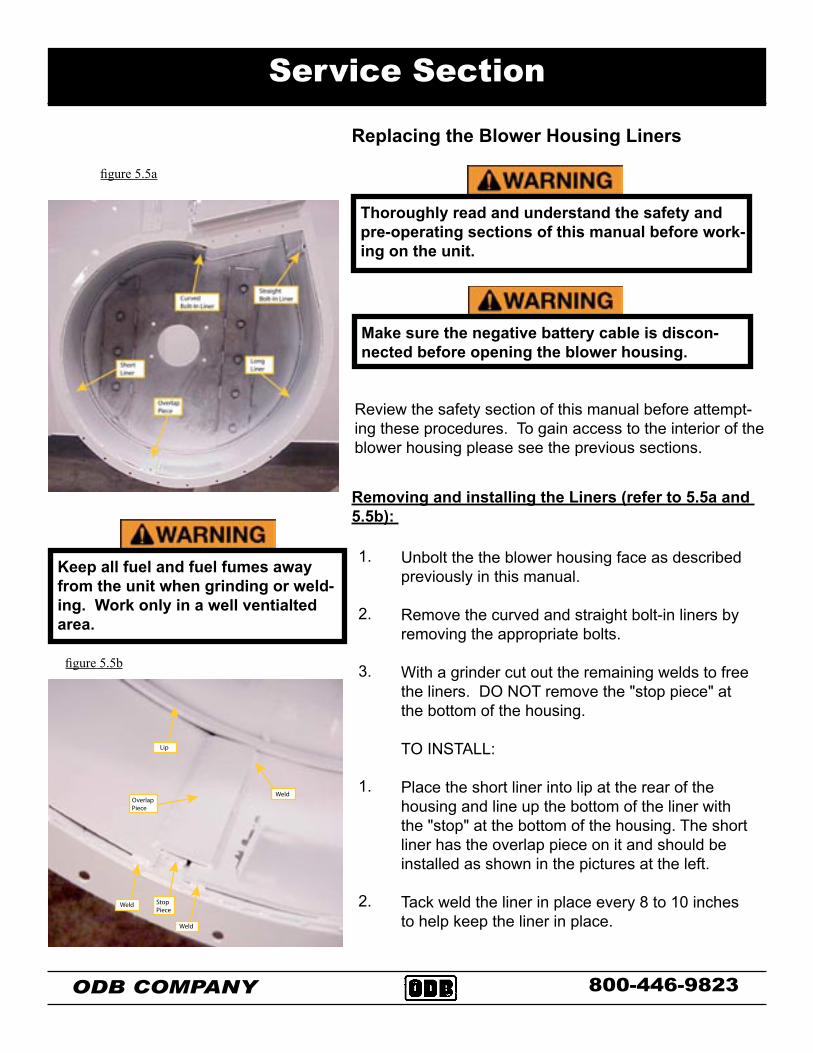
Replacing the Blower Housing Liners
Review the safety section of this manual before attempt-ing these procedures. To gain access to the interior of the blower housing please see the previous sections.
ODB COMPANY
Thoroughly read and understand the safety and pre-operating sections of this manual before work-ing on the unit.
figure 5.5a
Unbolt the the blower housing face as described previously in this manual.
Remove the curved and straight bolt-in liners by removing the appropriate bolts.
With a grinder cut out the remaining welds to free the liners. DO NOT remove the "stop piece" at the bottom of the housing.
TO INSTALL:
Place the short liner into lip at the rear of the housing and line up the bottom of the liner with the "stop" at the bottom of the housing. The short liner has the overlap piece on it and should be installed as shown in the pictures at the left.
Tack weld the liner in place every 8 to 10 inches to help keep the liner in place.
Removing and installing the Liners (refer to 5.5a and 5.5b):
1.
2.
3.
1.
2.
800-446-9823
Make sure the negative battery cable is discon-nected before opening the blower housing.
figure 3c
Keep all fuel and fuel fumes away from the unit when grinding or weld-ing. Work only in a well ventialted area.
����
����
���������
����
���
������������
figure 5.5b
ODB COMPANY 800-446-9823
Service Section
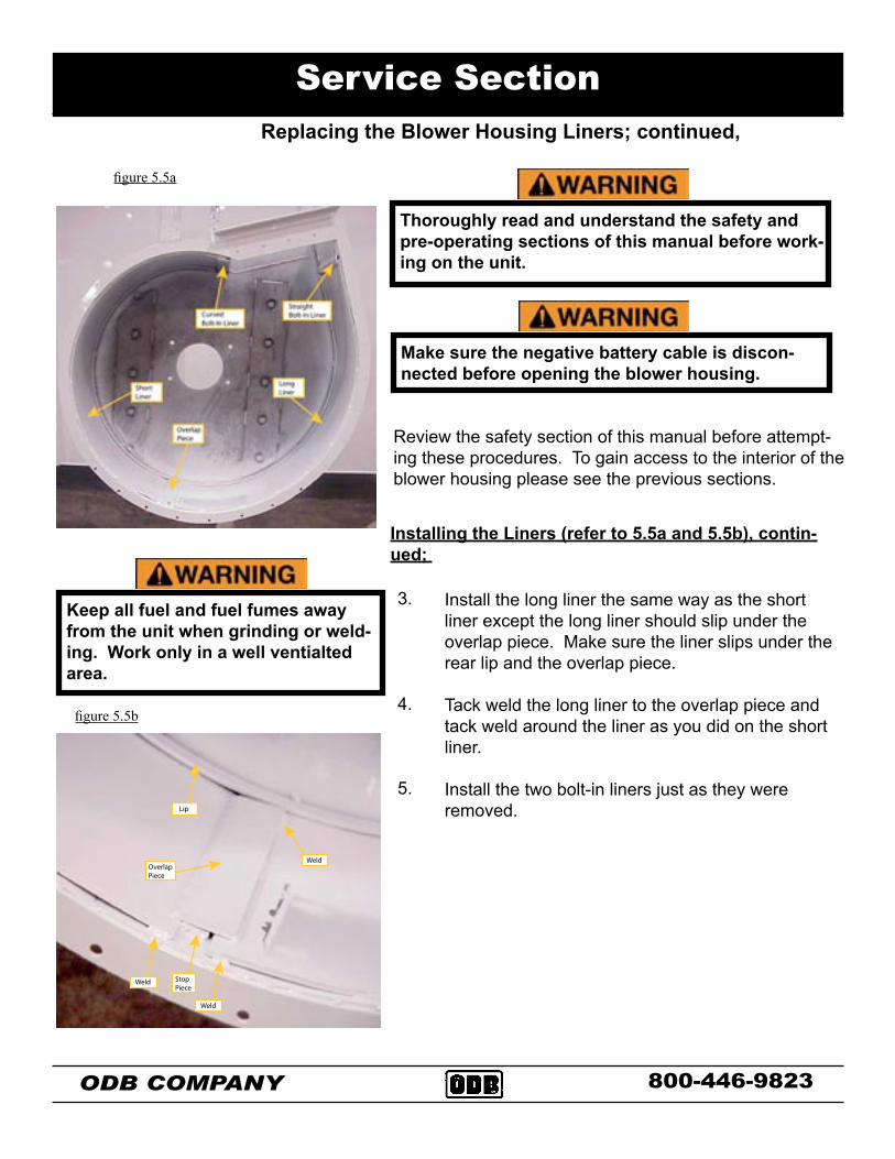
Review the safety section of this manual before attempt-ing these procedures. To gain access to the interior of the blower housing please see the previous sections.
Thoroughly read and understand the safety and pre-operating sections of this manual before work-ing on the unit.
figure 5.5a
Install the long liner the same way as the short liner except the long liner should slip under the overlap piece. Make sure the liner slips under the rear lip and the overlap piece.
Tack weld the long liner to the overlap piece and tack weld around the liner as you did on the short liner.
Install the two bolt-in liners just as they were removed.
Installing the Liners (refer to 5.5a and 5.5b), contin-ued;
3.
4.
5.
Make sure the negative battery cable is discon-nected before opening the blower housing.
figure 3c
Keep all fuel and fuel fumes away from the unit when grinding or weld-ing. Work only in a well ventialted area.
����
����
���������
����
���
������������
figure 5.5b
Replacing the Blower Housing Liners; continued,
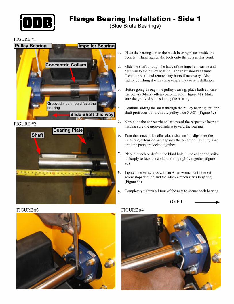
Flange Bearing Installation - Side 1(Blue Brute Bearings)
Place the bearings on to the black bearing plates inside the pedistal. Hand tighten the bolts onto the nuts at this point.
Slide the shaft through the back of the impeller bearing and half way to the pulley bearing. The shaft should fit tight. Clean the shaft and remove any burrs if necessary. Also lightly polishing it with a fine emery may ease installation.
Before going through the pulley bearing, place both concen-tric collars (black collars) onto the shaft (figure #1). Make sure the grooved side is facing the bearing.
Continue sliding the shaft through the pulley bearing until the shaft protrudes out from the pulley side 5-5/8". (Figure #2)
Now slide the concentric collar toward the respective bearing making sure the grooved side is toward the bearing.
Turn the concentric collar clockwise until it slips over the inner ring extension and engages the eccentric. Turn by hand until the parts are locket together.
Place a punch or drift in the blind hole in the collar and strike it sharply to lock the collar and ring tightly together (figure #3)
Tighten the set screws with an Allen wrench until the set screw stops turning and the Allen wrench starts to spring.(Figure #4)
Completely tighten all four of the nuts to secure each bearing.
1.
2.
3.
4.
5.
6.
7.
8.
9.
FIGURE #1
FIGURE #2
FIGURE #3 FIGURE #4
OVER...
Impeller BearingPulley Bearing
Slide Shaft this way
Concentric Collars
Shaft
Grooved side should face the bearing
Bearing Plate
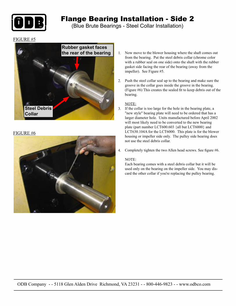
Flange Bearing Installation - Side 2 (Blue Brute Bearings - Steel Collar Installation)
Now move to the blower housing where the shaft comes out from the bearing. Put the steel debris collar (chrome color with a rubber seal on one side) onto the shaft with the rubber gasket side facing the rear of the bearing (away from the impeller). See Figure #5.
Push the steel collar seal up to the bearing and make sure the groove in the collar goes inside the groove in the bearing. (Figure #6) This creates the sealed fit to keep debris out of the bearing.
NOTE:If the collar is too large for the hole in the bearing plate, a "new style" bearing plate will need to be ordered that has a larger diameter hole. Units manufactured before April 2002 will most likely need to be converted to the new bearing plate (part number LCT600.603 {all but LCT6000} and LCT630.104A for the LCT6000. This plate is for the blower housing or impeller side only. The pulley side bearing does not use the steel debris collar.
Completely tighten the two Allen head screws. See figure #6.
NOTE:Each bearing comes with a steel debris collar but it will be used only on the bearing on the impeller side. You may dis-card the other collar if you're replacing the pulley bearing.
1.
2.
3.
4.
FIGURE #5
FIGURE #6
Grooved side should face the bearing
Rubber Gasket faces the rear of the bearing
ODB Company - - 5118 Glen Alden Drive Richmond, VA 23231 - - 800-446-9823 - - www.odbco.com
Steel DebrisCollar
Rubber gasket faces the rear of the bearing
THETHETHETHETHE
WIRING DIAGRAMS*Engine Wiring Diagram*Circuit Board Wiring Diagram*Trailer Wiring Diagram*Boom Pump Wiring Diagram
WIR
ING
DIA
GR
AM
S
800-446-9823
ODB COMPODB COMPODB COMPODB COMPODB COMPANYANYANYANYANY5118 Glen Alden DriveRichmond, VA 23231
Starter Solenoid(#ST40)
Connected to Bottom of Circ. Board
Alternator
To Auxillary Board on SCL's (RED)
Wiring Harness(#276D.WH1CB3)
Starter Motor on Engine
Battery
Red, 4ga. wire(Item #1)
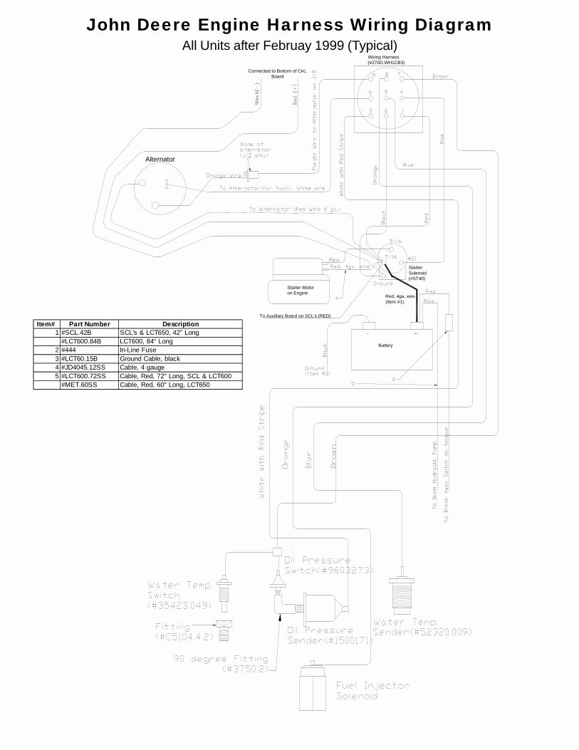
John Deere Engine Harness Wiring DiagramAll Units after Februay 1999 (Typical)
Item# Part Number Description1 #SCL.42B SCL's & LCT650, 42" Long
#LCT600.84B LCT600, 84" Long2 #444 In-Line Fuse3 #LCT60.15B Ground Cable, black4 #JD4045.12SS Cable, 4 gauge 5 #LCT600.72SS Cable, Red, 72" Long, SCL & LCT600
#MET.60SS Cable, Red, 60" Long, LCT650
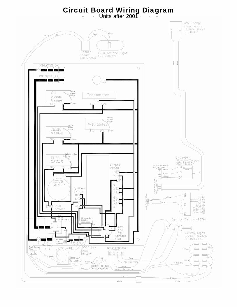
Circuit Board Wiring DiagramAll Units after April 2001 (Typical)Units after 2001
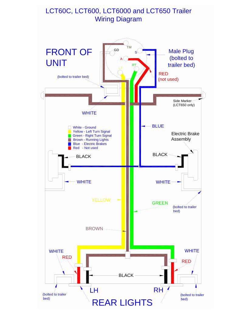
WHITE
YELLOWGREEN
BROWN
WHITERED
RED
REAR LIGHTS
WHITE
Male Plug (bolted to
trailer bed)
(bolted to trailer bed)
(bolted to trailer bed)
(bolted to trailer bed)
FRONT OFUNIT
LH RH
LCT60C, LCT600, LCT6000 and LCT650 Trailer Wiring Diagram
TM
S
A
RTLT
GD
White - GroundYellow - Left Turn SignalGreen - Right Turn SignalBrown - Running LightsBlue - Electric BrakesRed - Not used
BLUE
RED (not used)
BLACK
Electric BrakeAssembly
Side Marker(LCT650 only)
(bolted to trailer bed)
WHITE WHITE
BLACKBLACK
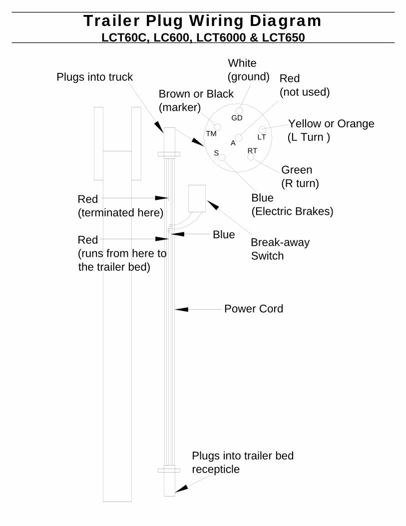
White (ground) Red
(not used)
Yellow or Orange(L Turn )
Green (R turn)
Blue (Electric Brakes)
Brown or Black(marker)
Red (terminated here)
Red (runs from here tothe trailer bed)
BlueBreak-away Switch
Plugs into truck
Plugs into trailer bedrecepticle
GD
TMA
S RT
LT
Power Cord
Trailer Plug Wiring DiagramLCT60C, LC600, LCT6000 & LCT650
THETHETHETHETHE
PARTS BREAKDOWNSSECTION
Engine GroupClutch GroupBlower Housing GroupTrailer GroupHose Boom Group
PAR
TS
BR
EA
KD
OW
N S
EC
TIO
N
800-446-9823
ODB COMPODB COMPODB COMPODB COMPODB COMPANYANYANYANYANY5118 Glen Alden DriveRichmond, VA 23231
THETHETHETHETHE
ENGINE GROUP*Instrument Panel*Air Cleaner*Engine Sheet Metal*Engine Mount*Engine Exhaust*Radiator Assembly*Remote Throtte Assembly (optional)*Chaffe Eliminator (optional)
EN
GIN
E G
RO
UP
800-446-9823
ODB COMPODB COMPODB COMPODB COMPODB COMPANYANYANYANYANY5118 Glen Alden DriveRichmond, VA 23231
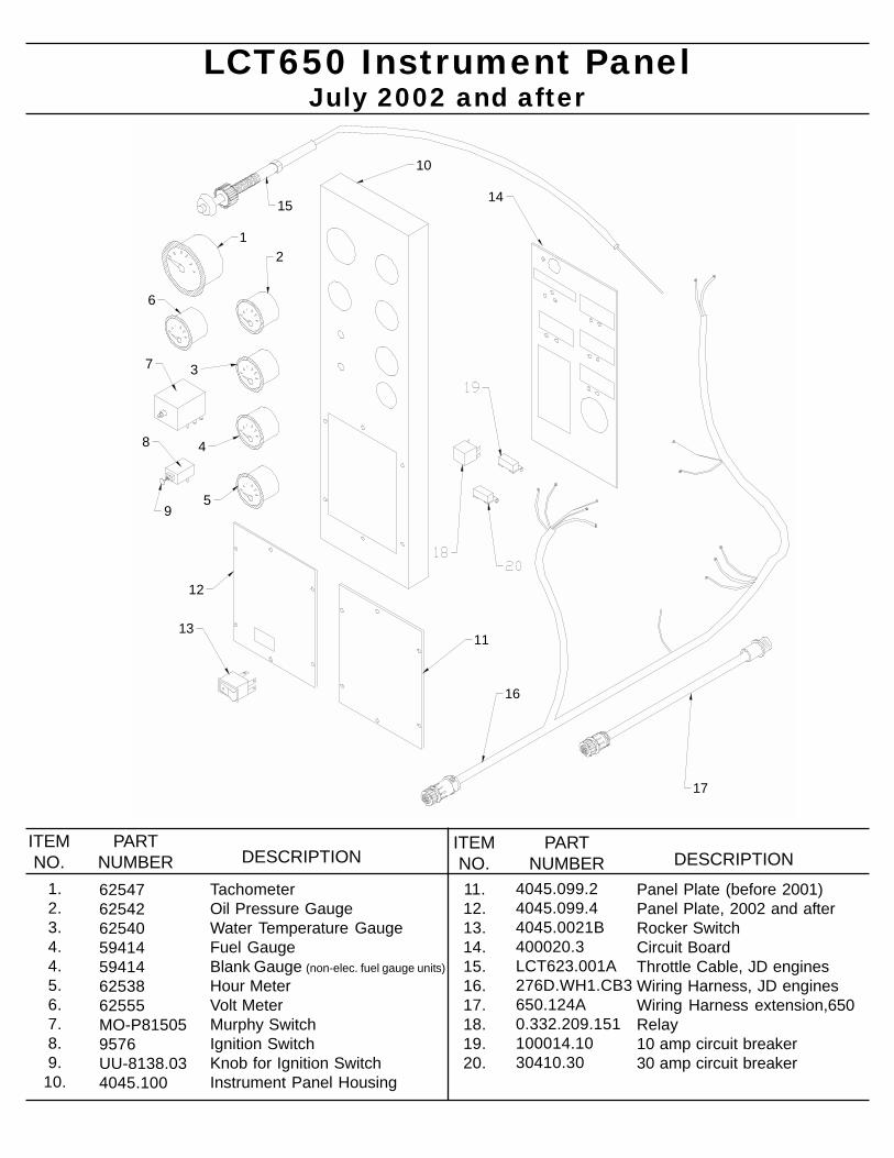
LCT650 Instrument Panel
TachometerOil Pressure GaugeWater Temperature GaugeFuel GaugeBlank Gauge (non-elec. fuel gauge units)Hour MeterVolt MeterMurphy SwitchIgnition SwitchKnob for Ignition SwitchInstrument Panel Housing
62547625426254059414594146253862555MO-P815059576UU-8138.034045.100
1.2.3.4.4.5.6.7.8.9.
10.
ITEMNO.
PARTNUMBER DESCRIPTION
July 2002 and after
Panel Plate (before 2001)Panel Plate, 2002 and afterRocker SwitchCircuit BoardThrottle Cable, JD enginesWiring Harness, JD enginesWiring Harness extension,650Relay10 amp circuit breaker30 amp circuit breaker
4045.099.24045.099.44045.0021B400020.3LCT623.001A276D.WH1.CB3650.124A0.332.209.151100014.1030410.30
11.12.13.14.15.16.17.18.19.20.
ITEMNO.
PARTNUMBER DESCRIPTION
12
3
4
5
6
7
8
9
11
12
13
1415
16
10
17
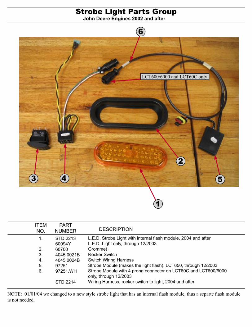
Strobe Light Parts Group
L.E.D. Strobe Light with internal flash module, 2004 and afterL.E.D. Light only, through 12/2003GrommetRocker SwitchSwitch Wiring HarnessStrobe Module (makes the light flash), LCT650, through 12/2003Strobe Module with 4 prong connector on LCT60C and LCT600/6000 only, through 12/2003Wiring Harness, rocker switch to light, 2004 and after
STD.221360094Y607004045.0021B4045.0024B9725197251.WH
STD.2214
1.
2.3.4.5.6.
ITEMNO.
PARTNUMBER DESCRIPTION
John Deere Engines 2002 and after
NOTE: 01/01/04 we changed to a new style strobe light that has an internal flash module, thus a separte flash module is not needed.
2
1
3 54
LCT600/6000 and LCT60C only
6
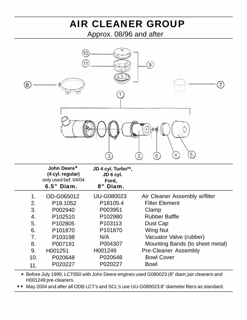
AIR CLEANER GROUP
Air Cleaner Assembly w/filter Filter Element Clamp Rubber Baffle Dust Cap Wing Nut Vacuator Valve (rubber) Mounting Bands (to sheet metal)Pre-Cleaner Assembly Bowl Cover Bowl
OD-G065012 P18.1052 P002940 P102510 P102805 P101870 P103198 P007191H001251 P020648 P020227
1.2.3.4.5.6.7.8.9.10.11.
John Deere
Ford,(4 cyl. regular)
only used bef. 04/04
JD 4 cyl. Turbo**,JD 6 cyl.
UU-G080023 P18105.4 P003951 P102980 P103113 P101870 N/A P004307H001249 P020648 P020227
*
* Before July 1999, LCT650 with John Deere engines used G080023 (8" diam,)air cleaners andH001249 pre-cleaners.
8 7
Approx. 08/96 and after
6.5" Diam. 8" Diam.
** May 2004 and after all ODB LCT's and SCL's use UU-G080023 8" diameter fiters as standard.
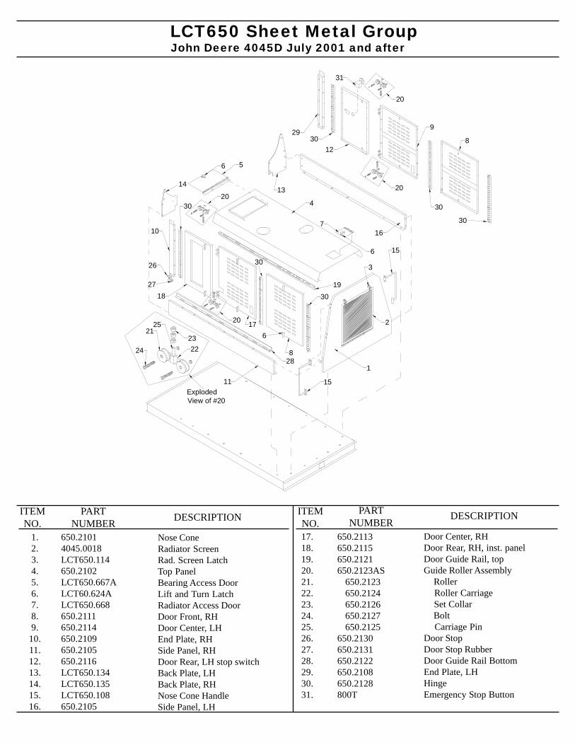
John Deere 4045D July 2001 and afterLCT650 Sheet Metal Group
1.2.3.4.5.6.7.8.9.
10.11.12.13.14.15.16.
650.21014045.0018LCT650.114650.2102LCT650.667ALCT60.624ALCT650.668650.2111650.2114650.2109650.2105650.2116LCT650.134LCT650.135LCT650.108650.2105
17.18.19.20.21.22.23.24.25.26.27.28.29.30.31.
Door Center, RHDoor Rear, RH, inst. panelDoor Guide Rail, topGuide Roller Assembly Roller Roller Carriage Set Collar Bolt Carriage PinDoor StopDoor Stop RubberDoor Guide Rail BottomEnd Plate, LHHingeEmergency Stop Button
650.2113650.2115650.2121650.2123AS 650.2123 650.2124 650.2126 650.2127 650.2125650.2130650.2131650.2122650.2108650.2128800T
PARTNUMBER DESCRIPTIONITEM
NO.DESCRIPTIONPART
NUMBERITEMNO.
Nose ConeRadiator ScreenRad. Screen LatchTop PanelBearing Access DoorLift and Turn LatchRadiator Access DoorDoor Front, RHDoor Center, LHEnd Plate, RHSide Panel, RHDoor Rear, LH stop switchBack Plate, LHBack Plate, RHNose Cone HandleSide Panel, LH
1
2
3
4
56
7
11
16
1314
6
15
15
8
176
1819
28
20
20
20
20
30
30
30
10
29
26
27
9
812
30
30
30
21
2223
24
Exploded View of #20
31
25
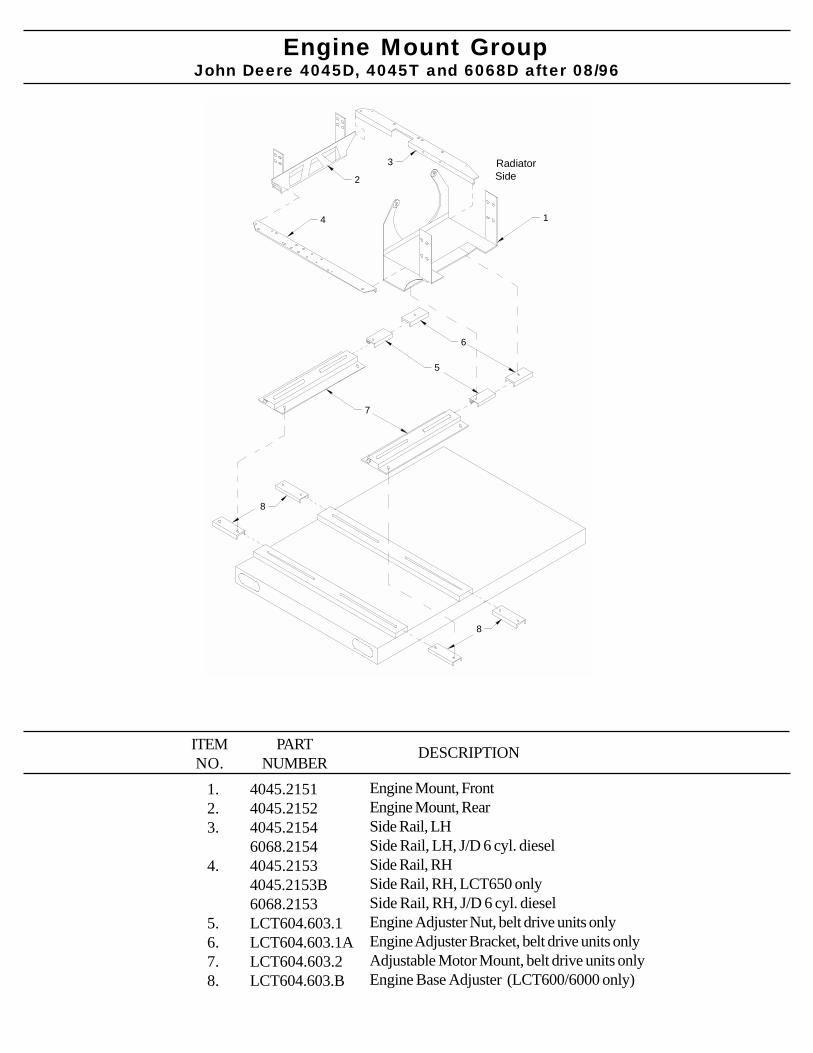
John Deere 4045D, 4045T and 6068D after 08/96Engine Mount Group
1.2.3.
4.
5.6.7.8.
4045.21514045.21524045.21546068.21544045.21534045.2153B6068.2153LCT604.603.1LCT604.603.1ALCT604.603.2LCT604.603.B
PARTNUMBER
DESCRIPTIONITEMNO.
Engine Mount, FrontEngine Mount, RearSide Rail, LHSide Rail, LH, J/D 6 cyl. dieselSide Rail, RHSide Rail, RH, LCT650 onlySide Rail, RH, J/D 6 cyl. dieselEngine Adjuster Nut, belt drive units onlyEngine Adjuster Bracket, belt drive units onlyAdjustable Motor Mount, belt drive units onlyEngine Base Adjuster (LCT600/6000 only)
Radiator Side
1
2
3
4
5
6
7
8
8
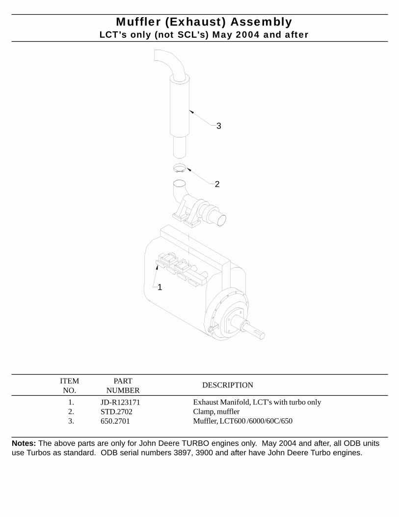
Muffler (Exhaust) AssemblyLCT's only (not SCL's) May 2004 and after
1.2.3.
JD-R123171STD.2702650.2701
PARTNUMBER
DESCRIPTIONITEMNO.
Exhaust Manifold, LCT's with turbo onlyClamp, mufflerMuffler, LCT600 /6000/60C/650
Notes: The above parts are only for John Deere TURBO engines only. May 2004 and after, all ODB unitsuse Turbos as standard. ODB serial numbers 3897, 3900 and after have John Deere Turbo engines.
1
2
3
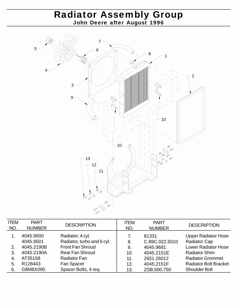
1
2
3
4
5 6
7
8
9
10
10
1112
13
Radiator Assembly Group
Radiator, 4 cyl.Radiator, turbo and 6 cyl.Front Fan ShroudRear Fan ShroudRadiator FanFan SpacerSpacer Bolts, 4 req.
4045.95004045.95014045.2190B4045.2190AAT35158R128443G8M8X090
1.
2.3.4.5.6.
ITEMNO.
PARTNUMBER DESCRIPTION
John Deere after August 1996
Upper Radiator HoseRadiator CapLower Radiator HoseRadiator ShimRadiator GrommetRadiator Bolt BracketShoulder Bolt
81331C.89C.022.50104045.96814045.2151E2651.260124045.2151FZSB.500.750
7.8.9.
10.11.12.13.
ITEMNO.
PARTNUMBER DESCRIPTION
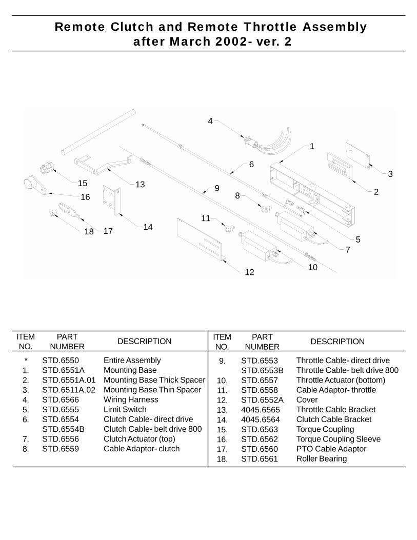
Remote Clutch and Remote Throttle Assembly after March 2002- ver. 2
Entire AssemblyMounting BaseMounting Base Thick SpacerMounting Base Thin SpacerWiring HarnessLimit SwitchClutch Cable- direct driveClutch Cable- belt drive 800Clutch Actuator (top)Cable Adaptor- clutch
STD.6550STD.6551ASTD.6551A.01STD.6511A.02STD.6566STD.6555STD.6554STD.6554BSTD.6556STD.6559
*1.2.3.4.5.6.
7.8.
ITEMNO.
PARTNUMBER DESCRIPTION
Throttle Cable- direct driveThrottle Cable- belt drive 800Throttle Actuator (bottom)Cable Adaptor- throttleCoverThrottle Cable BracketClutch Cable BracketTorque CouplingTorque Coupling SleevePTO Cable AdaptorRoller Bearing
STD.6553STD.6553BSTD.6557STD.6558STD.6552A4045.65654045.6564STD.6563STD.6562STD.6560STD.6561
9.
10.11.12.13.14.15.16.17.18.
ITEMNO.
PARTNUMBER DESCRIPTION
1
2
3
4
5
6
7
89
10
11
12
13
14
1516
1718
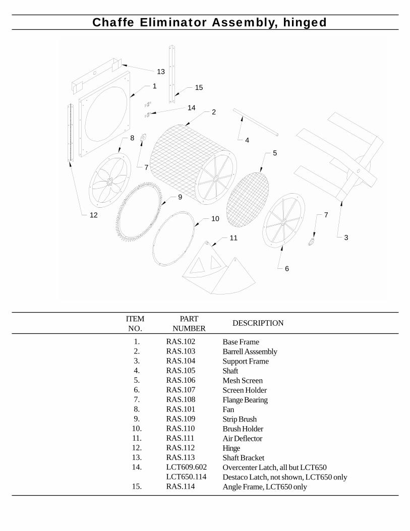
Chaffe Eliminator Assembly, hinged
1.2.3.4.5.6.7.8.9.10.11.12.13.14.
15.
RAS.102RAS.103RAS.104RAS.105RAS.106RAS.107RAS.108RAS.101RAS.109RAS.110RAS.111RAS.112RAS.113LCT609.602LCT650.114RAS.114
PARTNUMBER
DESCRIPTIONITEMNO.
Base FrameBarrell AsssemblySupport FrameShaftMesh ScreenScreen HolderFlange BearingFanStrip BrushBrush HolderAir DeflectorHingeShaft BracketOvercenter Latch, all but LCT650Destaco Latch, not shown, LCT650 onlyAngle Frame, LCT650 only
1
2
3
4
6
7
7
11
10
9
8
5
12
13
14
15
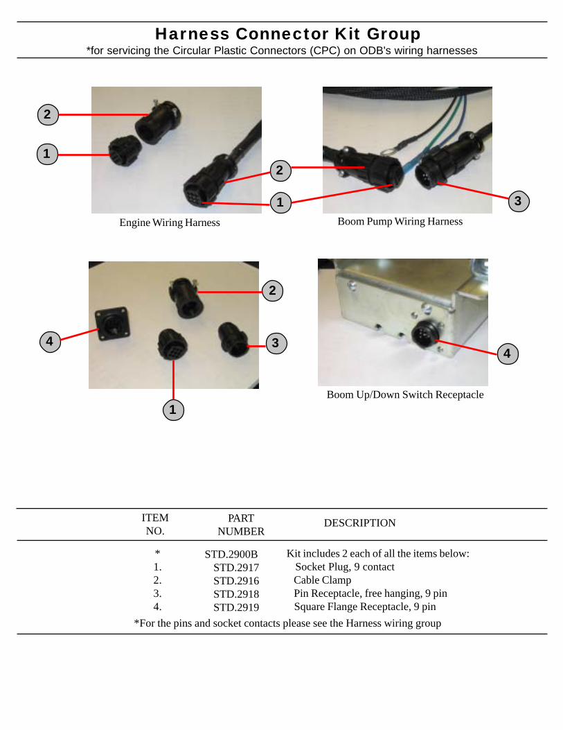
Harness Connector Kit Group
*1.2.3.4.
DESCRIPTIONITEMNO.
Kit includes 2 each of all the items below: Socket Plug, 9 contact Cable Clamp Pin Receptacle, free hanging, 9 pin Square Flange Receptacle, 9 pin
PARTNUMBER
STD.2900B STD.2917 STD.2916 STD.2918 STD.2919
*for servicing the Circular Plastic Connectors (CPC) on ODB's wiring harnesses
1
Boom Pump Wiring HarnessEngine Wiring Harness
2
Boom Up/Down Switch Receptacle1
2
1
2
344
*For the pins and socket contacts please see the Harness wiring group
3
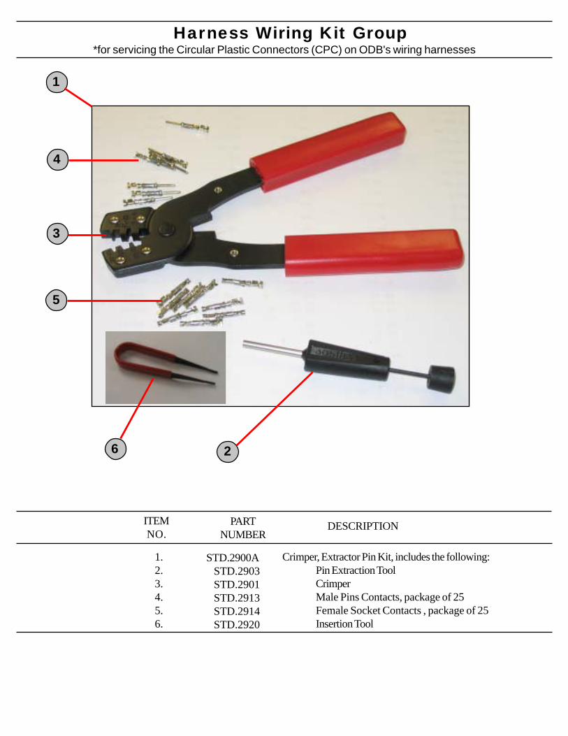
Harness Wiring Kit Group
1.2.3.4.5.6.
DESCRIPTIONITEMNO.
Crimper, Extractor Pin Kit, includes the following:Pin Extraction ToolCrimperMale Pins Contacts, package of 25Female Socket Contacts , package of 25Insertion Tool
PARTNUMBER
STD.2900A STD.2903 STD.2901 STD.2913 STD.2914 STD.2920
*for servicing the Circular Plastic Connectors (CPC) on ODB's wiring harnesses
2
4
5
3
1
6
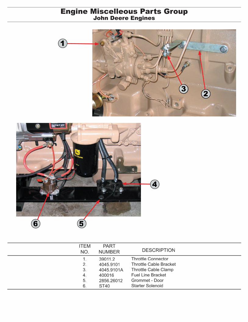
Engine Miscelleous Parts GroupJohn Deere Engines
Throttle ConnectorThrottle Cable BracketThrottle Cable ClampFuel Line BracketGrommet - DoorStarter Solenoid
39011.24045.91014045.9101A4000162856.26012ST40
1.2.3.4.5.6.
ITEMNO.
PARTNUMBER DESCRIPTION
6
1
2
4
5
3
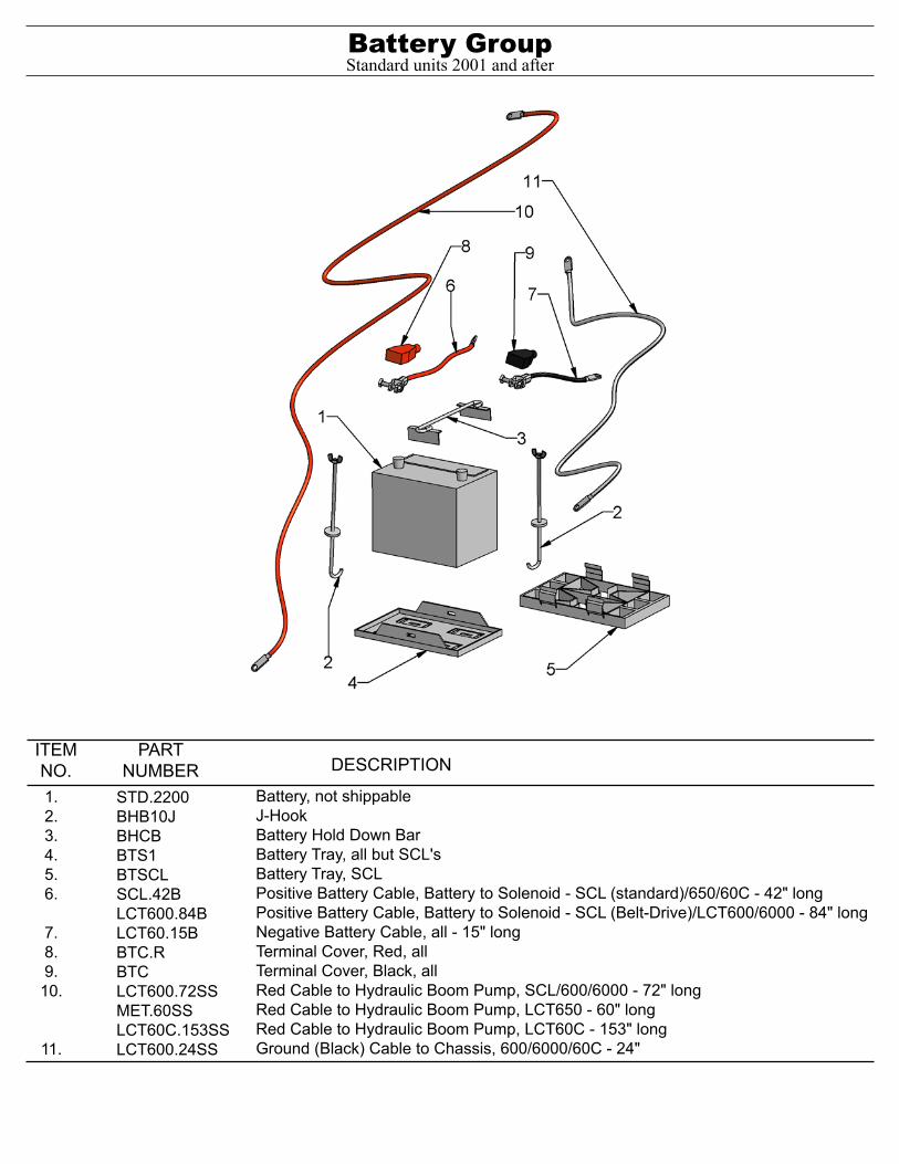
Battery, not shippableJ-Hook Battery Hold Down BarBattery Tray, all but SCL'sBattery Tray, SCLPositive Battery Cable, Battery to Solenoid - SCL (standard)/650/60C - 42" longPositive Battery Cable, Battery to Solenoid - SCL (Belt-Drive)/LCT600/6000 - 84" longNegative Battery Cable, all - 15" longTerminal Cover, Red, allTerminal Cover, Black, allRed Cable to Hydraulic Boom Pump, SCL/600/6000 - 72" longRed Cable to Hydraulic Boom Pump, LCT650 - 60" longRed Cable to Hydraulic Boom Pump, LCT60C - 153" longGround (Black) Cable to Chassis, 600/6000/60C - 24"
STD.2200BHB10JBHCBBTS1BTSCLSCL.42BLCT600.84BLCT60.15BBTC.RBTCLCT600.72SSMET.60SSLCT60C.153SSLCT600.24SS
ITEMNO.
PARTNUMBER DESCRIPTION
Battery Group
1.2.3.4.5.6.
7.8.9.
10.
11.
Standard units 2001 and after
THETHETHETHETHE
CLUTCH GROUP*Clutch Breakdown*Auto PTO Breakdown*Auto PTO Linkage*Clutch Assist Breakdown
CLU
TCH
GR
OU
P
800-446-9823
ODB COMPODB COMPODB COMPODB COMPODB COMPANYANYANYANYANY5118 Glen Alden DriveRichmond, VA 23231
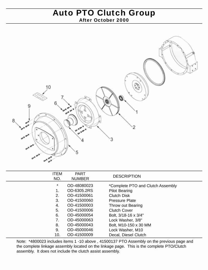
Auto PTO Clutch Group
*Complete PTO and Clutch AssemblyPilot BearingClutch DiskPressure PlateThrow out BearingClutch CoverBolt, 3/18-16 x 3/4"Lock Washer, 3/8"Bolt, M10-150 x 30 MMLock Washer, M10Decal, Diesel Clutch
OD-48080023OD-6305.2RSOD-41500061OD-41500060OD-41500003OD-41500006OD-45000054OD-45000063OD-45000043OD-45000046OD-41500009
*1.2.3.4.5.6.7.8.9.
10.
ITEMNO.
PARTNUMBER DESCRIPTION
After October 2000
Note: *4800023 includes items 1 -10 above , 41500137 PTO Assembly on the previous page andthe complete linkage assembly located on the linkage page. This is the complete PTO/Clutchassembly. It does not include the clutch assist assembly.
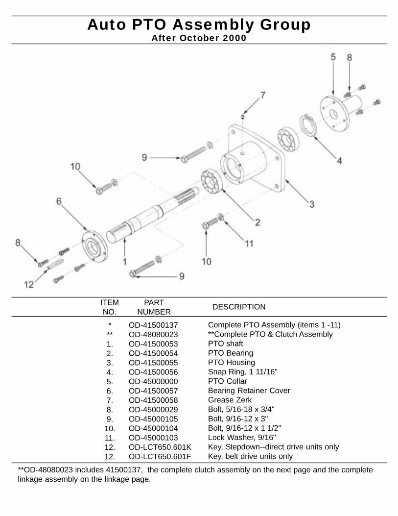
Auto PTO Assembly Group
Complete PTO Assembly (items 1 -11)**Complete PTO & Clutch AssemblyPTO shaftPTO BearingPTO HousingSnap Ring, 1 11/16"PTO CollarBearing Retainer CoverGrease ZerkBolt, 5/16-18 x 3/4"Bolt, 9/16-12 x 3"Bolt, 9/16-12 x 1 1/2"Lock Washer, 9/16"Key, Stepdown--direct drive units onlyKey, belt drive units only
OD-41500137OD-48080023OD-41500053OD-41500054OD-41500055OD-41500056OD-45000000OD-41500057OD-41500058OD-45000029OD-45000105OD-45000104OD-45000103OD-LCT650.601KOD-LCT650.601F
***1.2.3.4.5.6.7.8.9.
10.11.12.12.
ITEMNO.
PARTNUMBER DESCRIPTION
After October 2000
**OD-48080023 includes 41500137, the complete clutch assembly on the next page and the completelinkage assembly on the linkage page.
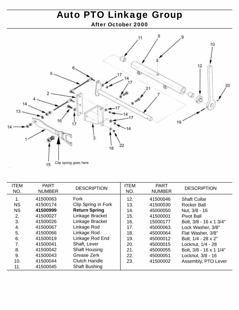
Auto PTO Linkage Group
ForkClip Spring in ForkReturn SpringLinkage BracketLinkage BracketLinkage RodLinkage RodLinkage Rod EndShaft, LeverShaft HousingGrease ZerkClutch HandleShaft Bushing
41500063415001744150099941500027415000264150006741500066415000194150004141500042415000434150004441500045
1. NSNS2.3.4.5.6.7.8.9.
10.11.
ITEMNO.
PARTNUMBER DESCRIPTION
After October 2000
ITEMNO.
PARTNUMBER DESCRIPTION
12.13.14.15.16.17.18.19.20.21.22.23.
415000464150003045000050415000011500017745000063450000644500001245000015450000554500005141500002
Shaft CollarRocker BallNut, 3/8 - 16Pivot BallBolt, 3/8 - 16 x 1 3/4"Lock Washer, 3/8"Flat Washer, 3/8"Bolt, 1/4 - 28 x 2"Locknut, 1/4 - 28Bolt, 3/8 - 16 x 1 1/4"Locknut, 3/8 - 16Assembly, PTO Lever
Clip spring goes here
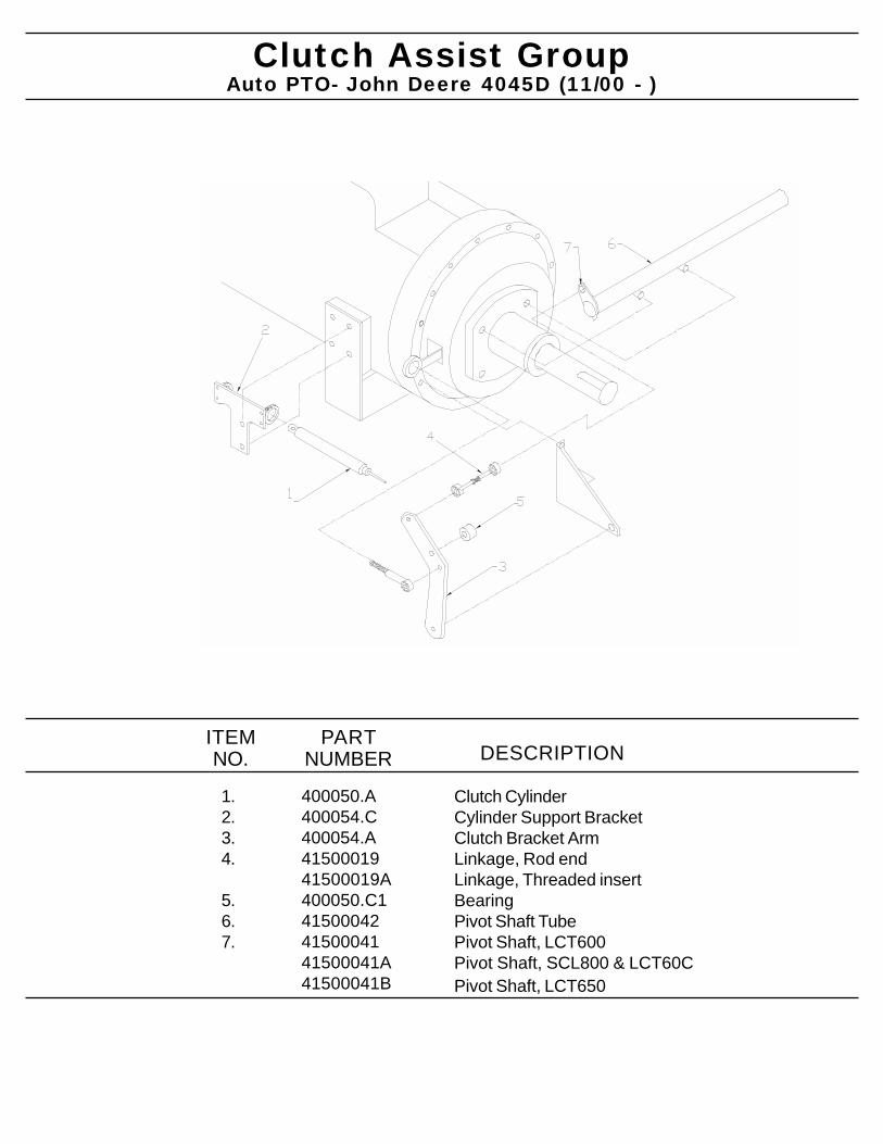
Clutch Assist Group
Clutch CylinderCylinder Support BracketClutch Bracket ArmLinkage, Rod endLinkage, Threaded insertBearingPivot Shaft TubePivot Shaft, LCT600Pivot Shaft, SCL800 & LCT60CPivot Shaft, LCT650
400050.A400054.C400054.A4150001941500019A400050.C1415000424150004141500041A41500041B
1.2.3.4.
5.6.7.
ITEMNO.
PARTNUMBER DESCRIPTION
Auto PTO- John Deere 4045D (11/00 - )

THETHETHETHETHE
BLOWER HOUSING GROUP*Impeller & Blower Breakdown*Pedestal & Bearing Assembly*Exhaust Duct Assembly
BLO
WE
R H
OU
SIN
G G
RO
UP
800-446-9823
ODB COMPODB COMPODB COMPODB COMPODB COMPANYANYANYANYANY5118 Glen Alden DriveRichmond, VA 23231
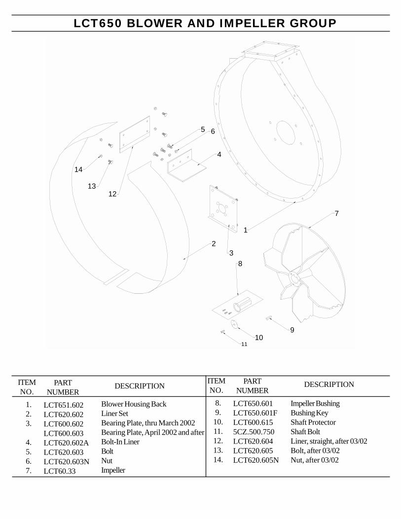
LCT650 BLOWER AND IMPELLER GROUP
1.2.3.
4.5.6.7.
DESCRIPTIONITEMNO.
Blower Housing BackLiner SetBearing Plate, thru March 2002Bearing Plate, April 2002 and afterBolt-In LinerBoltNutImpeller
PARTNUMBER
LCT651.602LCT620.602LCT600.602LCT600.603LCT620.602ALCT620.603LCT620.603NLCT60.33
1
23
4
5 6
8
910
7
11
1213
14
8.9.10.11.12.13.14.
DESCRIPTIONITEMNO.
Impeller BushingBushing KeyShaft ProtectorShaft BoltLiner, straight, after 03/02Bolt, after 03/02Nut, after 03/02
PARTNUMBER
LCT650.601LCT650.601FLCT600.6155CZ.500.750LCT620.604LCT620.605LCT620.605N
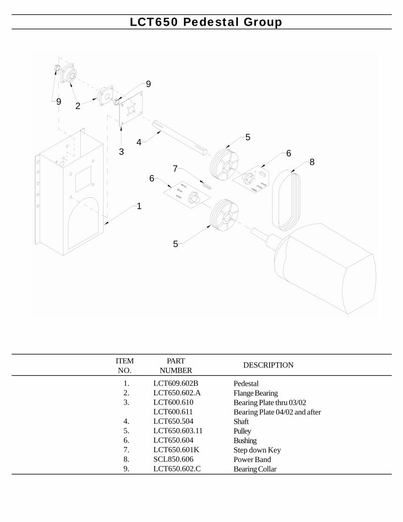
LCT650 Pedestal Group
1.2.3.
4.5.6.7.8.9.
LCT609.602BLCT650.602.ALCT600.610LCT600.611LCT650.504LCT650.603.11LCT650.604LCT650.601KSCL850.606LCT650.602.C
PARTNUMBER
DESCRIPTIONITEMNO.
PedestalFlange BearingBearing Plate thru 03/02Bearing Plate 04/02 and afterShaftPulleyBushingStep down KeyPower BandBearing Collar
1
2
34 5
5
6
67
8
9
9
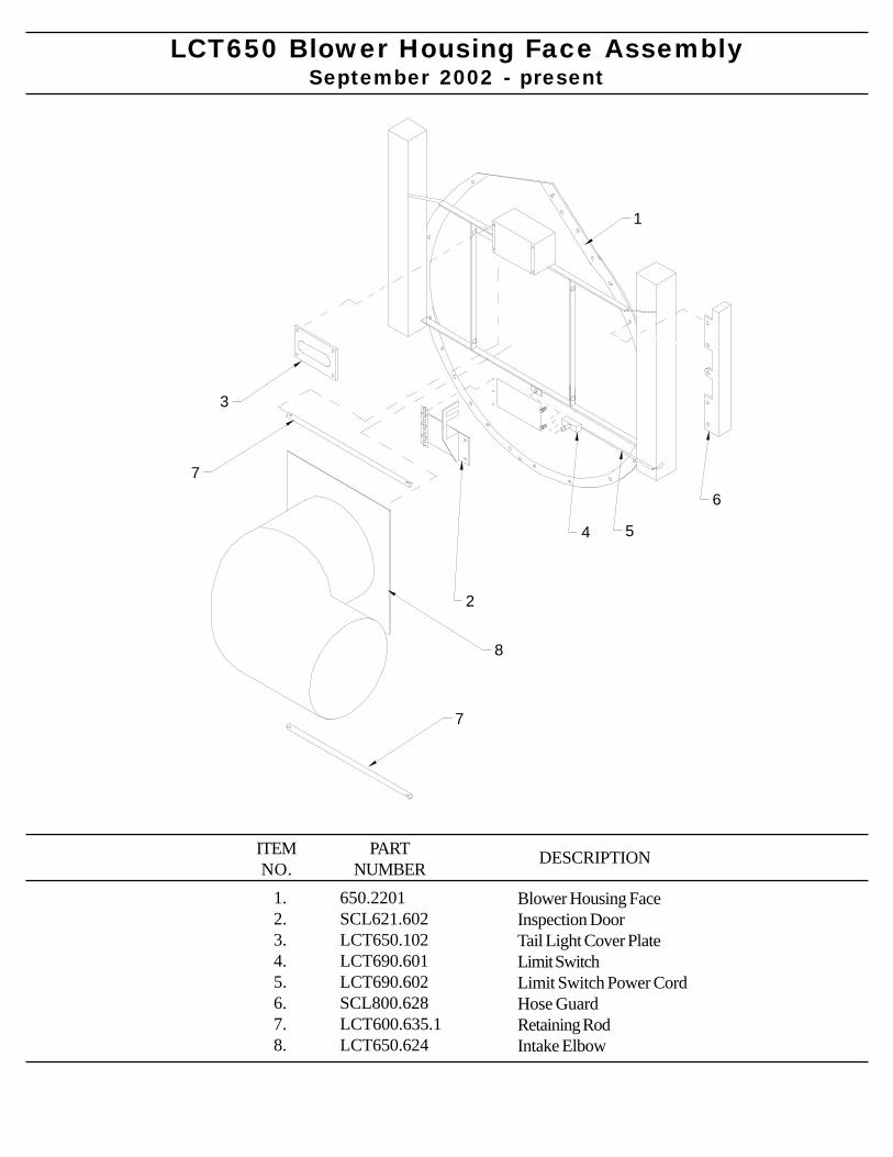
LCT650 Blower Housing Face AssemblySeptember 2002 - present
1.2.3.4.5.6.7.8.
650.2201SCL621.602LCT650.102LCT690.601LCT690.602SCL800.628LCT600.635.1LCT650.624
PARTNUMBER
DESCRIPTIONITEMNO.
Blower Housing FaceInspection DoorTail Light Cover PlateLimit SwitchLimit Switch Power CordHose GuardRetaining RodIntake Elbow
1
2
3
4 5
6
7
8
7
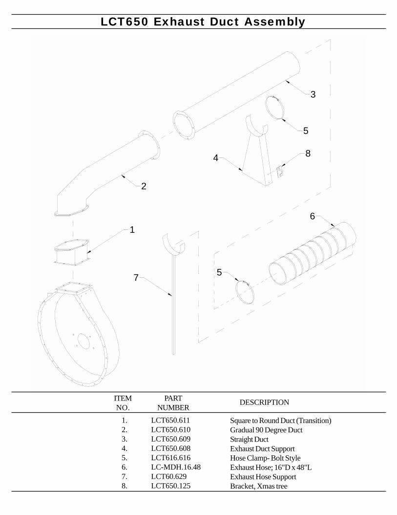
1
2
3
5
4
6
57
8
LCT650 Exhaust Duct Assembly
1.2.3.4.5.6.7.8.
LCT650.611LCT650.610LCT650.609LCT650.608LCT616.616LC-MDH.16.48LCT60.629LCT650.125
PARTNUMBER
DESCRIPTIONITEMNO.
Square to Round Duct (Transition)Gradual 90 Degree DuctStraight DuctExhaust Duct SupportHose Clamp- Bolt StyleExhaust Hose; 16"D x 48"LExhaust Hose SupportBracket, Xmas tree
THETHETHETHETHE
LCT650TRAILER GROUP
*Trailer Bed Assembly*Fuel Tank Assembly*Tongue Assembly*Axle Hub Assembly*Electric Brake Assembly
TR
AILE
R G
RO
UP
800-446-9823
ODB COMPODB COMPODB COMPODB COMPODB COMPANYANYANYANYANY5118 Glen Alden DriveRichmond, VA 23231
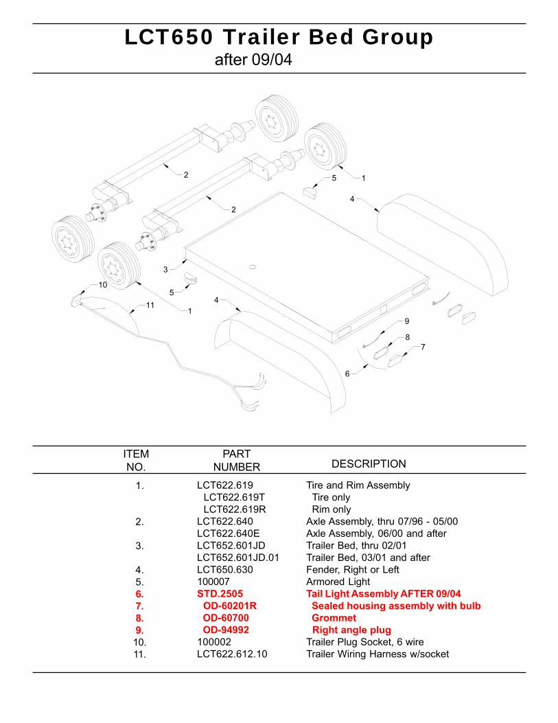
LCT650 Trailer Bed Group
Tire and Rim Assembly Tire only Rim onlyAxle Assembly, thru 07/96 - 05/00Axle Assembly, 06/00 and afterTrailer Bed, thru 02/01Trailer Bed, 03/01 and afterFender, Right or LeftArmored LightTail Light Assembly AFTER 09/04 Sealed housing assembly with bulb Grommet Right angle plugTrailer Plug Socket, 6 wireTrailer Wiring Harness w/socket
1.
2.
3.
4.5.6.7.8.9.10.11.
ITEMNO.
PARTNUMBER DESCRIPTION
LCT622.619 LCT622.619T LCT622.619RLCT622.640LCT622.640ELCT652.601JDLCT652.601JD.01LCT650.630100007STD.2505 OD-60201R OD-60700 OD-94992100002LCT622.612.10
after 09/04
1
4
52
2
3
54
10
11
9
87
6
1
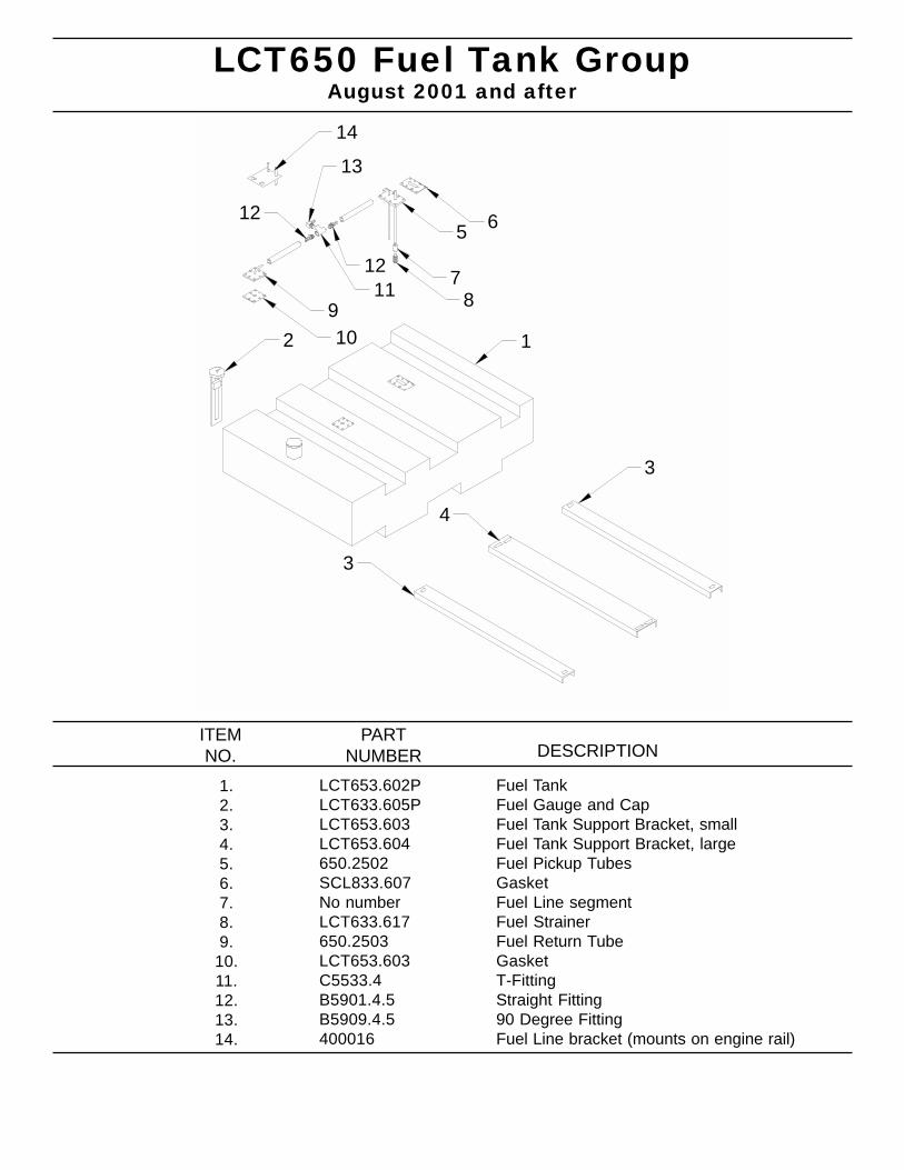
12
3
4
3
5 6
789
10
1112
12
13
14
LCT650 Fuel Tank Group
Fuel TankFuel Gauge and CapFuel Tank Support Bracket, smallFuel Tank Support Bracket, largeFuel Pickup TubesGasketFuel Line segmentFuel StrainerFuel Return TubeGasketT-FittingStraight Fitting90 Degree FittingFuel Line bracket (mounts on engine rail)
1.2.3.4.5.6.7.8.9.
10.11.12.13.14.
ITEMNO.
PARTNUMBER DESCRIPTION
LCT653.602PLCT633.605PLCT653.603LCT653.604650.2502SCL833.607No numberLCT633.617650.2503LCT653.603C5533.4B5901.4.5B5909.4.5400016
August 2001 and after
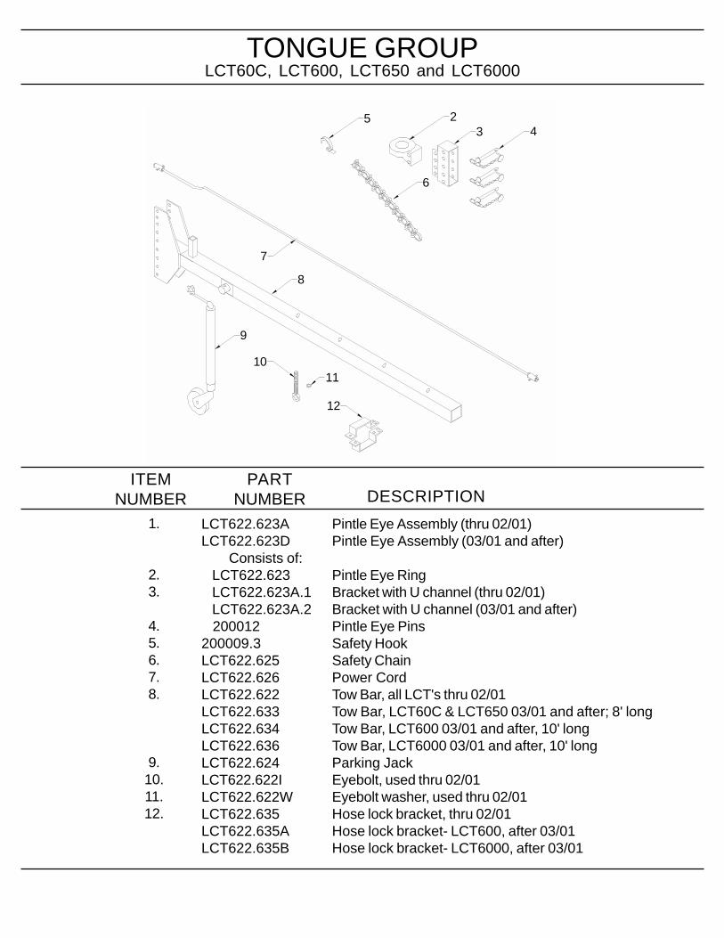
TONGUE GROUP
Pintle Eye Assembly (thru 02/01)Pintle Eye Assembly (03/01 and after)
Pintle Eye RingBracket with U channel (thru 02/01)Bracket with U channel (03/01 and after)Pintle Eye PinsSafety HookSafety ChainPower CordTow Bar, all LCT's thru 02/01Tow Bar, LCT60C & LCT650 03/01 and after; 8' longTow Bar, LCT600 03/01 and after, 10' longTow Bar, LCT6000 03/01 and after, 10' longParking JackEyebolt, used thru 02/01Eyebolt washer, used thru 02/01Hose lock bracket, thru 02/01Hose lock bracket- LCT600, after 03/01Hose lock bracket- LCT6000, after 03/01
LCT622.623ALCT622.623D Consists of: LCT622.623 LCT622.623A.1 LCT622.623A.2 200012200009.3LCT622.625LCT622.626LCT622.622LCT622.633LCT622.634LCT622.636LCT622.624LCT622.622ILCT622.622WLCT622.635LCT622.635ALCT622.635B
LCT60C, LCT600, LCT650 and LCT6000
1.
2.3.
4.5.6.7.8.
9.10.11.12.
ITEMNUMBER
PARTNUMBER DESCRIPTION
12
42
35
6
7
8
9
1011
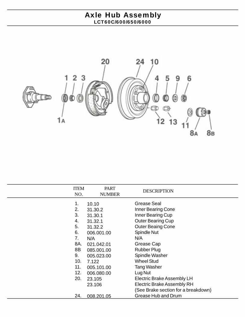
DESCRIPTIONITEMNO.
PARTNUMBER
1.2.3.4.5.6.7.8A.8B9.10.11.12.20.
24.
Grease SealInner Bearing ConeInner Bearing CupOuter Bearing CupOuter Beaing ConeSpindle NutN/AGrease CapRubber PlugSpindle WasherWheel StudTang WasherLug NutElectric Brake Assembly LHElectric Brake Assembly RH(See Brake section for a breakdown)Grease Hub and Drum
10.1031.30.231.30.131.32.131.32.2006.001.00N/A021.042.01085.001.00005.023.007.122005.101.00006.080.0023.10523.106
008.201.05
LCT60C/600/650/6000Axle Hub Assembly
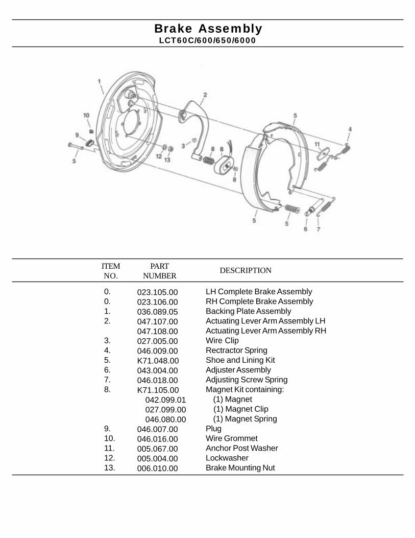
DESCRIPTIONITEMNO.
PARTNUMBER
0.0.1.2.
3.4.5.6.7.8.
9.10.11.12.13.
LH Complete Brake AssemblyRH Complete Brake AssemblyBacking Plate AssemblyActuating Lever Arm Assembly LHActuating Lever Arm Assembly RHWire ClipRectractor SpringShoe and Lining KitAdjuster AssemblyAdjusting Screw SpringMagnet Kit containing: (1) Magnet (1) Magnet Clip (1) Magnet SpringPlugWire GrommetAnchor Post WasherLockwasherBrake Mounting Nut
023.105.00023.106.00036.089.05047.107.00047.108.00027.005.00046.009.00K71.048.00043.004.00046.018.00K71.105.00 042.099.01 027.099.00 046.080.00046.007.00046.016.00005.067.00005.004.00006.010.00
LCT60C/600/650/6000Brake Assembly
THETHETHETHETHE
HOSE BOOM GROUP*Hose Boom Assembly*Intake Hose Assembly*Hydraulic Pump Assembly
HO
SE
BO
OM
GR
OU
P
800-446-9823
ODB COMPODB COMPODB COMPODB COMPODB COMPANYANYANYANYANY5118 Glen Alden DriveRichmond, VA 23231
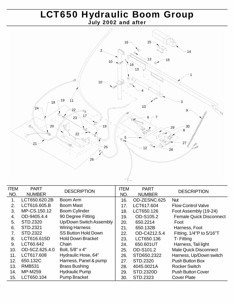
2
3
9
1
17
14
15
11
10
13
1310
4
16
1616
20
19
19
22
22
23
10
18
2521
26
24
12
5
28
3029
76
8
27
LCT650 Hydraulic Boom Group
Boom ArmBoom MastBoom Cylinder90 Degree FittingUp/Down Switch AssemblyWiring HarnessSS Button Hold DownHold Down BracketChainBolt, 5/8" x 4"Hydraulic Hose, 64"Harness, Panel & pumpBrass BushingHydraulic PumpPump Bracket
LCT650.620.2BLCT616.605.BMP-CS.150.12OD-9405.4.4STD.2320STD.2321STD.2322LCT616.615DLCT60.642OD-5CZ.625.4.0LCT617.608650.132CRMB531MP-M259LCT650.104
1.2.3.4.5.6.7.8.9.
10.11.12.13.14.15.
ITEMNO.
PARTNUMBER DESCRIPTION
July 2002 and after
NutFlow Control ValveFoot Assembly (19-24) Female Quick Disconnect Foot Harness, Foot Fitting, 1/4"P to 5/16"T T- Fitting Harness, Tail lightMale Quick DisconnectHarness, Up/Down switchPush Button BoxRocker SwitchPush Button CoverCover Plate
OD-ZESNC.625LCT617.604LCT650.126 OD-S105.2 650.2214 650.132B OD-C4212.5.4 LCT650.136 650.601UTOD-S101.2STD650.2322STD.23204045.0021ASTD.2320DSTD.2323
16.17.18.19.20.21.22.23.24.25.26.27.28.29.30.
ITEMNO.
PARTNUMBER DESCRIPTION
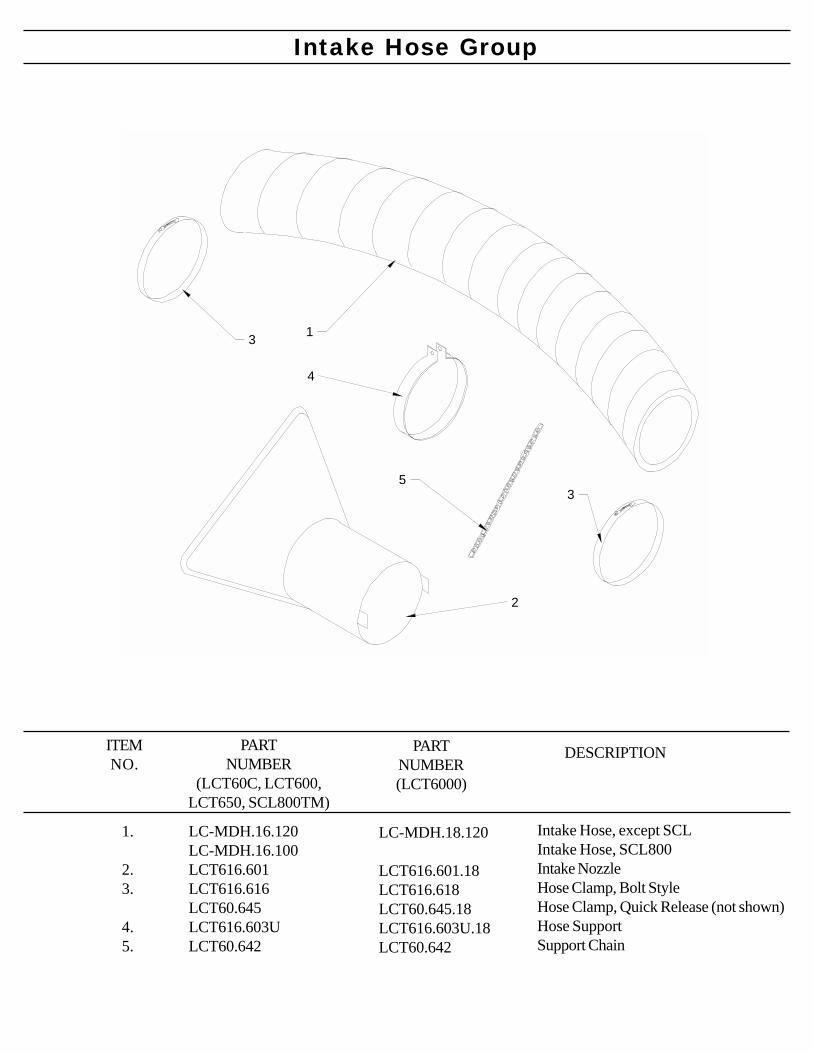
Intake Hose Group
1.
2.3.
4.5.
LC-MDH.16.120LC-MDH.16.100LCT616.601LCT616.616LCT60.645LCT616.603ULCT60.642
PARTNUMBER
(LCT60C, LCT600,LCT650, SCL800TM)
DESCRIPTIONITEMNO.
Intake Hose, except SCLIntake Hose, SCL800Intake NozzleHose Clamp, Bolt StyleHose Clamp, Quick Release (not shown)Hose SupportSupport Chain
1
2
3
3
4
5
PARTNUMBER(LCT6000)
LC-MDH.18.120
LCT616.601.18LCT616.618LCT60.645.18LCT616.603U.18LCT60.642
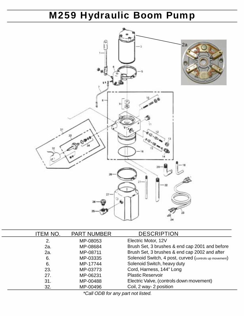
M259 Hydraulic Boom Pump
ITEM NO.2.
2a.2a.6.6.
23.27.31.32.
PART NUMBERMP-08053MP-08684MP-08711MP-03335MP-17744MP-03773MP-06231MP-00488MP-00496
Electric Motor, 12VBrush Set, 3 brushes & end cap 2001 and beforeBrush Set, 3 brushes & end cap 2002 and afterSolenoid Switch, 4 post, curved (controls up movement)Solenoid Switch, heavy dutyCord, Harness, 144" LongPlastic ReservoirElectric Valve, (controls down movement)Coil, 2 way- 2 position
*Call ODB for any part not listed.
DESCRIPTION
2a
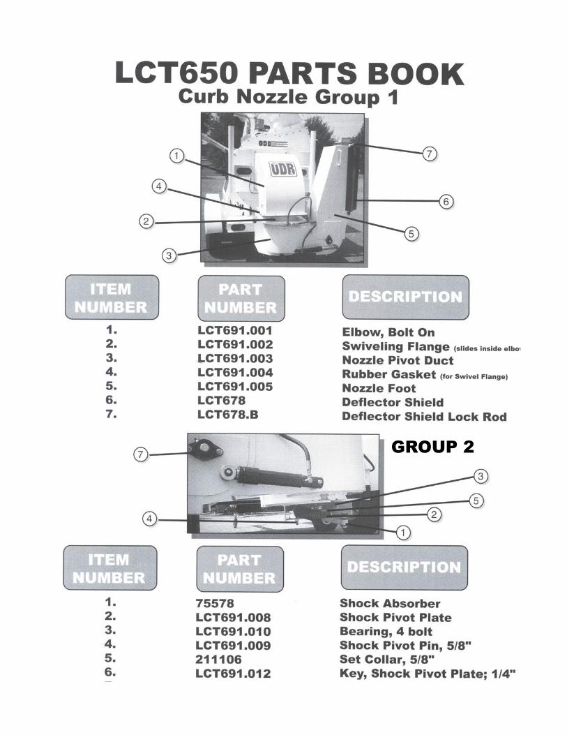
GROUP 2
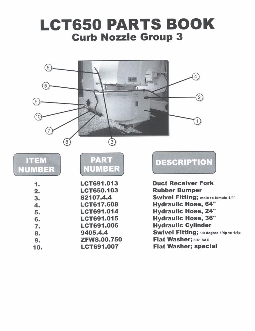

800-446-9823
ODB COMPODB COMPODB COMPODB COMPODB COMPANYANYANYANYANY
IMPROPER USE OF ANY MACHINE CANRESULT IN SERIOUS INJURY!
STUDY AND FOLLOW ALL SAFETYPRECAUTIONS BEFORE OPERATING OR
REPAIRING UNIT
5118 Glen Alden DriveRichmond, VA 23231
DO NOT ATTEMPT TO OPERATEOR REPAIR
THE LEAF COLLECTOR WITHOUT FIRSTREADING AND UNDERSTANDING THIS
MANUAL
IF YOU HAVE ANY QUESTIONS CONCERNING THEINSTALLATION OR OPERATION OF THIS UNIT, PLEASE CALL
ODB FOR ASSISTANCE BEFORE ATTEMPTING TO REPAIR OROPERATE THE UNIT.
THIS MANUAL IS AN INTEGRAL PART OF THE LEAF COLLECTOR ANDSHOULD BE KEPT WITH THE UNIT WHEN IT IS SOLD.

![Barnstead Water Purification Systems [ES]tools.thermofisher.com/content/sfs/brochures/BRWPOVERVIEW-ES-0413.pdf · Cina +800 810 5118 or +400 650 5118 Francia +33 2 2803 2180 Germania](https://img.pdfslide.us/doc/110x75/5c5c0bbf09d3f25e368cdf3c/barnstead-water-purification-systems-estools-cina-800-810-5118-or-400-650.jpg)


![[5118]-1collegecirculars.unipune.ac.in/sites/examdocs/April... · [5118]-1 3 P.T.O. (b) Draw a flowchart to find factorial of number. (c) Draw a flowchart for printing maximum of](https://img.pdfslide.us/doc/110x75/5e6f720db1f7b759a96cc421/5118-5118-1-3-pto-b-draw-a-flowchart-to-find-factorial-of-number-c.jpg)
![Barnstead Water Purification Systems [EN]... · China +800 810 5118 or +400 650 5118 France +33 2 2803 2180 ... • Remote dispenser provides full system control and ... have been](https://img.pdfslide.us/doc/110x75/60044ba42014854c434fb59b/barnstead-water-purification-systems-en-china-800-810-5118-or-400-650.jpg)