Embed Size (px)
Citation preview

INSTALLATION AND OPERATION MANUAL
XRS SERIESPOWERED AND PASSIVE
LOUDSPEAKERS
REV.2
IMPORTANT SAFETY INFORMATION PRÉCAUTIONS DURANT UTILISATION
2. Keep these instructions.
3. Heed all warnings.
4. Follow all instructions.
5. Do not use this apparatus near water.
6. Clean only with dry cloth.
7. Do not block any ventilation openings. Install in accordance with the manufacturer’s instructions.
8. Do not install near any heat sources such as radiators, heat registers, stoves, or other apparatus (including amplifiers) that produce heat.
9. Do not defeat the safety purpose of the polarized or grounding-type plug. A polarized plug has two blades with one wider than the other. A grounding type plug has two blades and a third grounding prong. The wide blade or the third prong are provided for your safety. If the provided plug does not fit into your outlet, consult an electrician for replacement of the obsolete outlet.
10. Protect the power cord from being walked on or pinched particularly at plugs, convenience receptacles, and the point where they exit from the apparatus.
11. Only use attachments/accessories specified by the manufacturer.
12. Use only with the cart, stand, tripod, bracket, or table specified by the manufacturer, or sold with the apparatus. When a cart is used, use caution when moving the cart/apparatus combination to avoid injury from tip-over.
13. Unplug this apparatus during lightning storms or when unused for long periods of time.
14. Refer all servicing to qualified service personnel. Servicing is required when the apparatus has been damaged in any way, such as power-supply cord or plug is damaged, liquid has been spilled or objects have fallen into the apparatus, the apparatus has been exposed to rain or moisture, does not operate normally, or has been dropped.
15. This appliance shall not be exposed to dripping or splashing water and that no object filled with liquid such as vases shall be placed on the apparatus.
16. Plug this apparatus to the proper wall outlet and make the plug to be disconnected readily operable.
17. Mains plug is used as disconnected device and it should remain readily operable during intended use. In order to disconnect the apparatus from the mains completely, the mains plug should be disconnected from the mains socket outlet completely.
18. WARNING: To reduce the risk of fire or electric shock, do not expose this apparatus to rain or moisture.
19. An appliance with a protective earth terminal should be connected to a mains outlet with a protective earth connection.
20. The apparatus should be disconnected from the mains completely before speaker wiring. The speaker output should be proper protected from direct contact and pay attention to speaker connections, terminals and speaker wiring during normal operation.
1. Lisez ces instructions.
2. Tenez ces instructions.
3. Notez tous les avertissements.
4. Suivez toutes les avertissements.
5. N’utilisez pas ce produit près de l’eau (la piscine, la plage, le lac, etc.).
6. Nettoyez seulement avec une étoffe sèche.
7. Ne bloquez aucuns troux de ventilation. Installez en accord avec les instructions du manufacturier.
8. N’installez près aucunes sources de chaleur comme radiateurs, registres de chaleur, fours ou les autres équipements (y compris amplificateurs) qui produisent la chaleur.
9. Ne défaites pas le but de sécurité de la fiche polarisée ou base-type. Une fiche polarisée a deux tranchants avec un plus large que l’autre. Une fiche de base type a deux a deux tranchants et une troisième pointe de base, le tranchant large ou la troisième pointe est fourni pour votre sécurité. Si la fiche donnée ne conforme pas votre prise de contact, consultez un électricien pour remplacement de la prise de contact obsolète.
10. Protegez le cordon de secteur contre être marchée dessus ou pincez en particulier aux fiches, aux douilles de convenance, et au point où ils sortent de l’appareil.
11. Seulement utilisez attachements/accessoires spécifiés par le manufacturier.
12. Utilisez seulement avec un chariot, un stand, un trépied, un support ou une table indiquée par le manufacturier, ou vendue avec l’appareil. Quand un chariot est utilisé, faites attention en déplaçant la combinaison d’appareil/chariot pour éviter de se déséquilibrer.
13. Arrachez la fiche du dispositif durant éclair et orage ou quand pas utilisé pour longues périodes de temps.
14. Référez au personnel qualifié de service pour toutes réparations. La réparation est donnée quand le système a été endommagé à n’importe façon, par exemple un fil ou une fiche endommagé(e) de la source d’alimentation. Avoir été exposé à pluie ou humidité, n’opère pas normalement, ou avoir été tombé.
15. L’appareil ne doit pas être exposé aux écoulements ou aux éclaboussures et aucun objet ne contenant de liquide, tel qu’un vase, ne doit être placé sur l’objet.
16. Branchez l’appareil à une source appropriée et faire que la prise à débrancher soit facilement accessible.
17. La prise du secteur ne doit pas être obstruée ou doit être facilement accessible pendant son utilisation. Pour être complètement déconnecté de l’alimentation d’entrée, la prise doit être débranchée du secteur.
18. AVERTISSEMENT: Pour éviter le risque d’incendie ou de chocs électriques, ne pas exposer cet appareil à la pluie ou à l’humidité.
19. Un appareil avec la borne de terre de protection doit être connecté au secteur avec la connexiion de terre de protection.
20. Assurez-vous que l’appareil est hors tension avant de connecter les hauts parleurs. Verifiez que la sortie des enceintes soit protégées contre un contact physique. Respecter les polarités des terminaux ainsi que le câblage des enceintes pendant le fonctionnement afin d’assurer une utilisation sécurisee.
1. Read these instructions.

XRS SERIESBuilding on the reliability and sonic quality of the very popular XR speaker series, Australian Monitor brings you the XRS two way injection moulded speaker enclosures with more features and new aesthetic to suit both live sound reinforcement and permanent installation. From front of house to foldback, the dance floor to background fill, the XRS series with passive, powered and constant voltage and weatherproof options are designed with flexibility and performance in mind.
The XRS range includes 6” (XRS6ODV), 8”, 10” and 12” models all with high quality compression drivers and represent a significant advancement in injection moulded box design while maintaining excellent audio quality and great value for money. The XRS series are available in both black (B) and white (W) models.
Revision 1.5 September 2012
XRS FRONT PANEL 4
XRS REAR PANEL – PASSIVE & CONSTANT VOLTAGE 5
XRS REAR PANEL POWERED VERSION 6
ACCESSORIES 7
SPECIFICATIONS 8
WARNING!
TO PREVENT FIRE OR SHOCK HAZARD, DO NOT USE THE PLUG WITH AN EXTENSION CORD, RECEPTACLE OR OTHER OUTLET UNLESS THE BLADES
CAN BE FULLY INSERTED TO PREVENT BLADE EXPOSURE.
TO REDUCE THE RISK OF FIRE OR ELECTRIC SHOCK, DO NOT EXPOSE THIS APPLIANCE TO RAIN OR MOISTURE.
TO PREVENT ELECTRICAL SHOCK, MATCH WIDE BLADE PLUG TO WIDE SLOT, FULLY INSERT.
CAUTIONRISK OF ELECTRIC SHOCK
DO NOT OPEN
The lightning flash with arrowhead symbol, within an equilateral triangle, is intended
to alert the user to the presence of uninsulated “dangerous voltage” within the product’s enclosure that may be of sufficient magnitude to constitute a risk
of electric shock to persons.
WARNING: TO REDUCE THE RISK OF ELECTRIC SHOCK, DO NOT REMOVE COVER (OR BACK). NO USER SERVICEABLE PARTS INSIDE. REFER
SERVICING TO QUALIFIED SERVICE PERSONNEL.
ADVERTISSMENT: POUR ÈVITER LE RISQUE D’INCENDIE OU DE CHOCS ÈLECTRIQUES,
NE PAS EXPOSER CET APPARIEL À LA PLUIE OU À L’HUMIDITÈ.
The exclamation point within an equilateral triangle is intended to alert the user to
the presence of important operating and maintenance (servicing) instructions in the
literature accompanying the appliance.
Rating plate and caution marking are marked on the back enclosure of the apparatus
PAGE 3XRS SERIES INSTALLATION AND OPERATION MANUAL
INTRODUCTION AND CONTENTS
INTRODUCTION 3
PAGE 4 XRS SERIES INSTALLATION AND OPERATION MANUAL
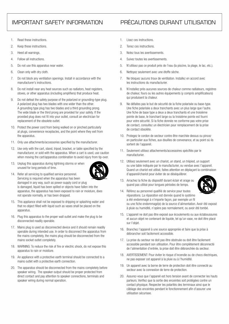
XRS FRONT PANEL – ALL VERSIONS
1 High Frequecy Driver
Horn loaded compression driver. Dispersion 90° H x 60° V for XRS6ODV and 90° H x 90° V for all other models
Passive crossover in the passive and constant voltage XRS varients.XRS6ODV 1” XRS8 1.5”XRS10 1.5”XRS12 2”
Active crossover and power amp in XRS powered varients.XRS8P 50 WXRS10P 50 WXRS12P 100 W
2 Low Frequency Woofer
Driver sizes:XRS6ODV 6” XRS8 8”XRS10 10”XRS12 12”
1 2
Made in China
Frequency Response (-3dB) 65Hz-18kHzSensitivity (dB 1W 1m) 92 dBImpedance 8 OhmRecommended Max Power (Program) 200W
1-
2 Way Full Range SpeakerBuilt-in Passive 2 Way Crossover
1+ 1- : INPUT
SN:
XRS8B
2+
1+2-
Made in ChinaSN:
XRS8ODV
100V 25W/70V N.C
100V 50W/70V 25W
8 OHM BYPASS
100V N.C/70V 100W100V 100W/70V 50W
2 Way Full Range SpeakerWeather Proof 100V/70V
Frequency Response (-3dB) 65Hz-18kHzSensitivity (dB 1W 1m) 92 dBImpedance 8 OhmRecommended Max Power (Program) 200W
PAGE 5XRS SERIES INSTALLATION AND OPERATION MANUAL
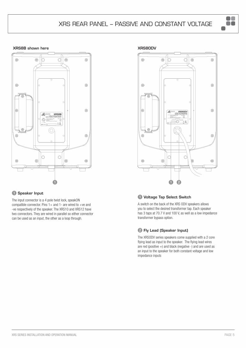
XRS REAR PANEL – PASSIVE AND CONSTANT VOLTAGE
1 Speaker Input
The input connector is a 4 pole twist lock, speakON compatible connector. Pins 1+ and 1- are wired to +ve and -ve respectively of the speaker. The XRS10 and XRS12 have two connectors. They are wired in parallel so either connector can be used as an input, the other as a loop through.
1 1 2
XRS8B shown here XRS8ODV
1 Voltage Tap Select Switch
A switch on the back of the XRS ODV speakers allows you to select the desired transformer tap. Each speaker has 3 taps at 70.7 V and 100 V, as well as a low impedance transformer bypass option.
2 Fly Lead (Speaker Input)
The XRSODV series speakers come supplied with a 2 core flying lead as input to the speaker. The flying lead wires are red (positive +) and black (negative -) and are used as an input to the speaker for both constant voltage and low impedance inputs

1 Mic In
Balanced XLR microphone input.
2 Mic Signal
Green LED Signal Present indicator for the Mic input. It indicates signal present on the input and is not affected by the level control.
3 Line In
Balanced XLR line level input.
4 Line Signal
Green LED Signal Present indicator for the Line input. Indicates signal is present at the input, it is not affected by the level control.
5 Line Out
LINE OUT is a line level output. This output can be connected to the LINE IN on another XRS Powered speaker to expand the system.
6 Output Clip
Red LED clip indicator for mixed mic and line audio signals. Some flashing of red is acceptable on program transients. Continuous flashing of red could indicate that undue stress is being placed on the speaker and will sound distorted. Turn down the input level until the clip LED is no longer lit.
7 Mic Level
Controls the level of the MIC input (1).
8 Mic Bass
Bass control for the MIC input (1). There is 12 dB of cut and boost at 100 Hz. This EQ is the shelving type.
9 Mic Treble
Treble control for the MIC input (1). There is 10 dB of cut and boost at 10 kHz. This EQ is the shelving type.
10 Line Level
Controls the level of the LINE input. (3)
11 Line Bass
Bass control for the LINE input (3). There is 12 dB of cut and boost at 100 Hz. This EQ is the shelving type.
12 Line Treble
Treble control for the LINE input (3). There is 10 dB of cut and boost at 10 kHz. This EQ is the shelving type.
13 Power Switch
Mains power switch to turn the speaker amplifier on and off.
14 IEC Mains Input Socket
XRS series powered speakers use a standard IEC 3 pin mains socket. A standard IEC mains cable is provided. The fuse drawer contains the mains fuse and a spare.
The mains fuse is a time lag (slow blow) HRC 20 x 5 mm ceramic or glass type fuse.
XRS8P XRS10P XRS12P
120 V 2.5 A 2.5 A 3.15 A
240 V 1.6 A 1.6 A 5.0 A
IMPORTANT: Always replace the fuse with one of the same value and type.
NOTE: Always disconnect power to the amplifier before replacing fuses.
15 Voltage Select Switch
This switch selects the mains voltage for your region. Choose either 240V or 120V.
IMPORTANT: Disconnect power to the amplifier before operating this switch.
IMPORTANT: Always ensure that the correct voltage for your area has been chosen before connecting the unit to the mains supply. Failure to do so may result in personal injury or damage to the unit.
PAGE 6 XRS SERIES INSTALLATION AND OPERATION MANUAL
XRS REAR PANEL POWERED VERSION
15 13 14
10 11 127 8 92 4 6
53
1

PAGE 7XRS SERIES INSTALLATION AND OPERATION MANUAL
MOUNTING & ACCESSORIES
MOUNTING
When mounting XRS series loudspeakers the following safety issues must be considered;
1. The mounting of a permanently installed speaker may be dangerous unless undertaken by a qualifified professional with relevant experience.
2. Walls and mounting surfaces must be capable of supporting the speaker and bracketry in a safe and secure manner.
3. Fixings must be safely attached to the speaker cabinet and the mounting surface. All fixings must be installed in accordance with the manufacturer’s instructions and specifications.
Suspending with Eyebolts
The XRS range of speaker cabinets provide a number of secured mounting points for use with M8 eye bolts.
As many eyebolt locations as possible should be used on the speaker. When mounting an XRS6ODV or XRS8 speaker cabinet, at least two or more mounting points must be used. For the XRS10 and XRS12 speaker cabinets, three or more points must be used. The best way to hang a speaker using eyebolts is to use two eyebolts on the top of the cabinet and one on the rear to give the speaker some angle.
All eyebolt fittings in the XRS range are M8 and require at least a 20 mm of thread length.
ACCESSORIES
XRS6ODV
XR6PMA Pole mount adaptor
XR6UMB Universal mount bracket
XRS6UB U bracket
XRS8
XR8PMA Pole mount adapter
XR8UMB Universal mounting bracket
XRS10
XR10CVR Heavy duty cover
AMISLSB1 Wall mount brackets
ATC303 Tripod speaker stand
ATC304 Heavy duty tripod speaker stand
ATC305 Winch up speaker stand
XR10-12UB Universal bracket
XRS12
XR12CVR Heavy duty cover
AMISLSB1 Wall mount brackets
ATC303 Tripod speaker stand
ATC304 Heavy duty tripod speaker stand
ATC305 Winch up speaker stand
XR10-12UB Universal bracket

XRS8B/W XRS10B/W XRS12B/W
Impedance 8 Ohms 8 Ohms 8 Ohms
Power (Continuous, Program) 100 W, 200 W 250 W, 500 W 300 W, 600 W
Sensitivity (1 W / 1 M) 92 dB 95 dB 97 dB
Calculated max SPL (Continuous, Peak) 112 dB, 118 dB 119 dB, 125 dB 121 dB, 128 dB
Dispersion (-6 dB Points) (H x V) 90° x 90° 90° x 90° 90° x 90°
Frequency Response (-3 dB) 65 Hz - 18 kHz 55 Hz - 18 kHz 50 Hz - 18 kHz
Frequency Response (-10 dB) 60 Hz - 20 kHz 50 Hz - 20 kHz 40 Hz - 20 kHz
Connection 4 pole twist lock connectors 4 pole twist lock connectors 4 pole twist lock connectors
Components 1 x 8” Woofer, 1 x 1.5” HF Driver 1 x 10” Woofer, 1 x 1.5” HF Driver 1 x 12” Woofer, 1 x 2” HF Driver
Net Dimensions (W x D x H) 277 x 257 x 400 mm (per single) 321 x 308 x 464 mm 415 x 382 x 620 mm (10.9” x 10.1” x 15.7”) (12.6” x 12.1” x 18.3”) (16.3” x 15.0” x 24.4”)
Shipping Dimensions (W x D x H) 595 x 310 x 460 mm (per pair) 375 x 355 x 535 mm 465 x 435 x 680 mm (23.4” x 12.2” x 18.1”) (14.8” x 14” x 21.1”) (16.3” x 15.4” x 23.6”)
Net Weight 6.5 kg (14.3 lbs) (per single) 10 kg (22 lbs) 18 kg (39.7 lbs)
Shipping Weight 15 kg (33.1 lbs) (per pair) 12 kg (26.5 lbs) 20 kg (44.1 lbs)
PAGE 8 XRS SERIES INSTALLATION AND OPERATION MANUAL
SPECIFICATIONS
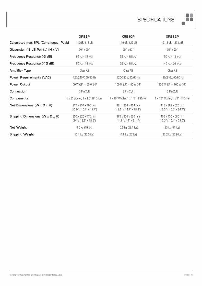
XRS8P XRS10P XRS12P
Calculated max SPL (Continuous, Peak) 112dB, 118 dB 119 dB, 125 dB 121.8 dB, 127.8 dB
Dispersion (-6 dB Points) (H x V) 90° x 90° 90° x 90° 90° x 90°
Frequency Response (-3 dB) 65 Hz - 18 kHz 55 Hz - 18 kHz 50 Hz - 18 kHz
Frequency Response (-10 dB) 55 Hz - 18 kHz 50 Hz - 18 kHz 40 Hz - 20 kHz
Amplifier Type Class AB Class AB Class AB
Power Requirements (VAC) 120/240 V, 50/60 Hz 120/240 V, 50/60 Hz 120/240V, 50/60 Hz
Power Output 100 W (LF) + 50 W (HF) 100 W (LF) + 50 W (HF) 300 W (LF) + 100 W (HF)
Connection 3 Pin XLR 3 Pin XLR 3 Pin XLR
Components 1 x 8" Woofer, 1 x 1.5" HF Driver 1 x 10" Woofer, 1 x 1.5" HF Driver 1 x 12" Woofer, 1 x 2" HF Driver
Net Dimensions (W x D x H) 277 x 257 x 400 mm 321 x 308 x 464 mm 415 x 382 x 620 mm (10.9” x 10.1” x 15.7”) (12.6” x 12.1” x 18.3”) (16.3” x 15.0” x 24.4”)
Shipping Dimensions (W x D x H) 355 x 325 x 470 mm 375 x 355 x 535 mm 465 x 435 x 680 mm (14” x 12.8” x 18.5”) (14.8” x 14” x 21.1”) (16.3” x 15.4” x 23.6”)
Net Weight 8.6 kg (19 lbs) 10.5 kg (23.1 lbs) 23 kg (51 lbs)
Shipping Weight 10.1 kg (22.3 lbs) 11.8 kg (26 lbs) 25.2 kg (55.6 lbs)
PAGE 9XRS SERIES INSTALLATION AND OPERATION MANUAL
SPECIFICATIONS

XRS6ODV XRS8ODV
Sensitivity (1 W / 1 M) 92 dB 92 dB
Dispersion (-6 dB Points) (H x V) 90° x 60° 90° x 90°
Frequency Response (-3 dB) 95 Hz - 18 kHz 65 Hz - 18 kHz
Frequency Response (-10 dB) 85 Hz - 20 kHz 60 Hz - 20 kHz
Connection Captive Fly Lead Captive Fly Lead
Components 1 x 6” Woofer 1 x 1” HF Driver 1 x 8" Woofer, 1 x 1.5" HF Driver
Net Dimensions (W x D x H) 225 x 200 x 325 mm 277 x 257 x 400 mm (8.9” x 7.9” x 12.8”) (10.9” x 10.1” x 15.7”)
Shipping Dimensions (W x D x H) 260 x 260 x 390 mm 355 x 325 x 470 mm (10.2” x 10.2” x 15.4”) (14” x 12.8” x 18.5”)
Net Weight 7 kg (15.4 lbs) 10 kg (22 lbs)
Shipping Weight 8.2 kg (18 lbs) 12 kg (26.5 lbs)
PAGE 10 XRS SERIES INSTALLATION AND OPERATION MANUAL
SPECIFICATIONS
Calculated max SPL (Continuous, Peak) 111 dB, 117 dB 112 dB, 118 dB
Power (Bypass Continuous / Program) 80 W, 160 W 100 W, 200 W
Impedance (Bypass) 8 Ohms 8 Ohms
Power (70 V, 100 V Tappings) 7.5 W, 15 W, 30, 60 W 15 W, 37.5 W, 75 W
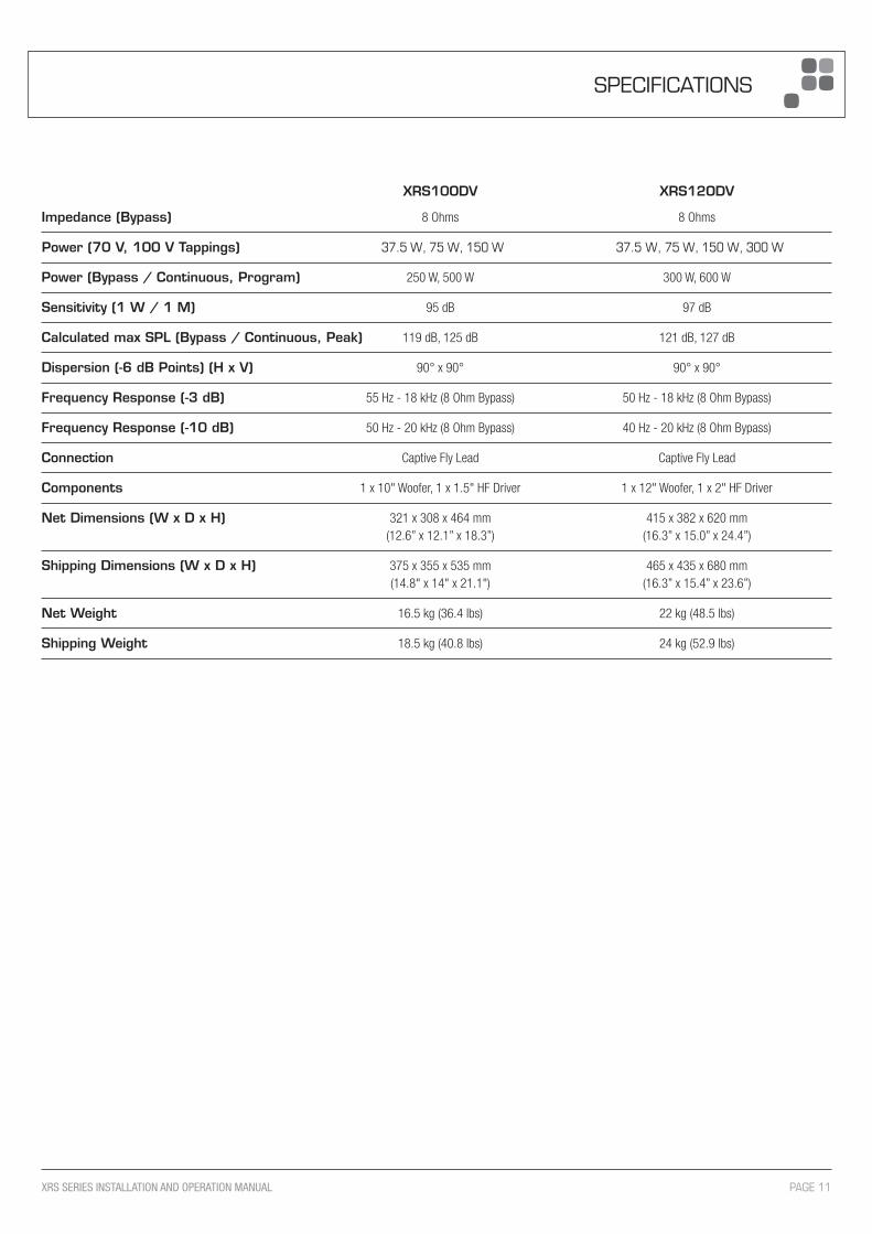
XRS10ODV XRS12ODV
Impedance (Bypass) 8 Ohms 8 Ohms
Power (Bypass / Continuous, Program) 250 W, 500 W 300 W, 600 W
Sensitivity (1 W / 1 M) 95 dB 97 dB
Calculated max SPL (Bypass / Continuous, Peak) 119 dB, 125 dB 121 dB, 127 dB
Dispersion (-6 dB Points) (H x V) 90° x 90° 90° x 90°
Frequency Response (-3 dB) 55 Hz - 18 kHz (8 Ohm Bypass) 50 Hz - 18 kHz (8 Ohm Bypass)
Frequency Response (-10 dB) 50 Hz - 20 kHz (8 Ohm Bypass) 40 Hz - 20 kHz (8 Ohm Bypass)
Connection Captive Fly Lead Captive Fly Lead
Components 1 x 10" Woofer, 1 x 1.5" HF Driver 1 x 12" Woofer, 1 x 2" HF Driver
Net Dimensions (W x D x H) 321 x 308 x 464 mm 415 x 382 x 620 mm (12.6” x 12.1” x 18.3”) (16.3” x 15.0” x 24.4”)
Shipping Dimensions (W x D x H) 375 x 355 x 535 mm 465 x 435 x 680 mm (14.8" x 14" x 21.1") (16.3” x 15.4” x 23.6”)
Net Weight 16.5 kg (36.4 lbs) 22 kg (48.5 lbs)
Shipping Weight 18.5 kg (40.8 lbs) 24 kg (52.9 lbs)
PAGE 11XRS SERIES INSTALLATION AND OPERATION MANUAL
SPECIFICATIONS
Power (70 V, 100 V Tappings) 37.5 W, 75 W, 150 W 37.5 W, 75 W, 150 W, 300 W

ENGINEERED BY AUSTRALIAN MONITOR Address: 1 Clyde Street, Silverwater, Sydney NSW 2128 Australia. Private Bag 149, Silverwater NSW 1811 ACN 007 573 417
DISTRIBUTED IN AUSTRALIA AND NEW ZEALAND BY HILLS SVL www.hillssvl.com.au NSW QLD ACT WA VIC SA NZ P: 02 9647 1411 P: 07 3852 1312 P: 02 6260 4544 P: 08 9204 0200 P: 03 9890 7477 P: 08 8408 8300 P: 09 415 9426 E: [email protected] E: [email protected] E: [email protected] E: [email protected] E: [email protected] E: [email protected] E: [email protected]
Website: www.australianmonitor.com.au International enquiries email: [email protected]