Embed Size (px)
Citation preview

6/2003
XpressNet Specification Includes using the
LI100/LI100F and LI101 Computer Interfaces to
extend XpressNet to a PC
Also includes descriptions for older X-Bus V1 and X-Bus V2 Commands

6/2003

XpressNet Protocol Description __________________________________________________________________________________
__________________________________________________________________________________ 3 Lenz Elektronik GmbH
1 General............................................................................................................................................. 6
1.1 XpressNet Architecture ......................................................................................................... 6 1.1.1 XpressNet timing constraints................................................................................................. 7 1.1.2 XpressNet Topology, wiring, and power considerations ....................................................... 8 1.1.3 Determining the version of the XpressNet............................................................................. 9 1.2 Receiving unrequested information..................................................................................... 9
1.3 Locomotive addresses in the digital plus system.............................................................. 9
1.4 Programming considerations for XpressNet devices ...................................................... 10
1.5 LI100 Computer Interface Specifications .......................................................................... 12 1.5.1 Differences between the LI100, LI100F, and LI101 ............................................................ 12 1.5.2 Messages from the LI100 .................................................................................................... 13 1.5.3 Special PC programming considerations ............................................................................ 14 1.5.4 Determining the Version number of the LI100F and LI101 ................................................. 15 1.5.5 Determing and changing the XpressNet address for the LI101 .......................................... 16 1.5.6 Determing and changing the Baud Rate for the LI101........................................................ 17 1.5.7 BREAK signal and RESET of the LI101F............................................................................ 18 1.6 Future Expansion................................................................................................................. 18
2 Communications between the DCC Command Station and XpressNet Devices................... 19
2.1 Data response commands from the command station to an XpressNet Device........... 19 2.1.1 Normal inquiry...................................................................................................................... 20 2.1.2 Request Acknowledgement from Device ............................................................................ 20 2.1.3 TBD (Future Command) ...................................................................................................... 21 2.1.4 Broadcast messages ........................................................................................................... 21 2.1.4.1 Normal operation resumed ............................................................................................... 21 2.1.4.2 Track power Off................................................................................................................. 22 2.1.4.3 Emergency Stop................................................................................................................ 22 2.1.4.4 Service Mode entry ........................................................................................................... 23 2.1.4.5 Feedback Broadcast ......................................................................................................... 23 2.1.5 Service Mode information response.................................................................................... 24 2.1.5.1 Programming info. " short-circuit " .................................................................................... 24 2.1.5.2 Programming info. "Data byte not found".......................................................................... 24 2.1.5.3 Programming info. "Command station busy" .................................................................... 25 2.1.5.4 Programming info. "Command station ready ".................................................................. 25 2.1.5.5 Service Mode response for Register and Paged Mode.................................................... 25 2.1.5.6 Service Mode response for Direct CV mode .................................................................... 26 2.1.6 Command Station software-version response .................................................................... 26 2.1.6.1 Software-version(X-Bus V1 and V2)................................................................................. 26 2.1.6.2 Software-version (XpressNet only) ................................................................................... 27 2.1.7 Command station status indication response...................................................................... 28 2.1.8 Transfer Errors..................................................................................................................... 29 2.1.9 Command station busy response........................................................................................ 29 2.1.10 Instruction not supported by command station.................................................................... 30 2.1.11 Accessory Decoder information response........................................................................... 30 2.1.12 Locomotive information response (X-Bus V1)..................................................................... 32 2.1.12.1 Locomotive is available for operation................................................................................ 32

XpressNet Protocol Description __________________________________________________________________________________
__________________________________________________________________________________ 4 Lenz Elektronik GmbH
2.1.12.2 Locomotive is being operated by another device ............................................................. 33 2.1.13 Locomotive information response (X-Bus V2)..................................................................... 34 2.1.13.1 Locomotive is available for operation................................................................................ 34 2.1.13.2 Locomotive is being operated by another device ............................................................. 36 2.1.14 Locomotive information response (XpressNet only)............................................................ 37 2.1.14.1 Locomotive information normal locomotive ...................................................................... 37 2.1.14.2 Locomotive information for a locomotive in a multi-unit.................................................... 38 2.1.14.3 Locomotive information for the Multi-unit address ............................................................ 39 2.1.14.4 Locomotive information for a locomotive in a Double Header .......................................... 39 2.1.15 Locomotive is being operated by another device response (XpressNet only) .................... 40 2.1.16 Function status response (XpressNet only) ....................................................................... 41 2.1.17 Locomotive information response for address retrieval requests (XpressNet only)............ 42 2.1.18 Double Header information response (X-Bus V1) ............................................................... 43 2.1.18.1 Double Header available................................................................................................... 43 2.1.18.2 Double Header occupied .................................................................................................. 44 2.1.19 Double Header information response (X-Bus V2) ............................................................... 44 2.1.19.1 Double Header available................................................................................................... 45 2.1.19.2 Double Header occupied .................................................................................................. 45 2.1.20 Double Header error response (X-Bus V1 and V2)............................................................. 46 2.1.21 XpressNet MU+DH error message response...................................................................... 47 2.2 Data sent from an XpressNet device to the command station........................................ 48 2.2.1 Acknowledgement Response.............................................................................................. 48 2.2.2 Resume operations request ................................................................................................ 49 2.2.3 Stop operations request (emergency off) ............................................................................ 49 2.2.4 Stop all locomotives request (emergency stop) .................................................................. 50 2.2.5 Emergency stop a specific locomotive operation ................................................................ 50 2.2.5.1 Emergency stop a locomotive (X-Bus V1 and V2)............................................................ 50 2.2.5.2 Emergency stop a locomotive (XpressNet) ...................................................................... 51 2.2.6 Emergency stop selected locomotives (X-Bus V1 and V2)................................................. 51 2.2.7 Register Mode read request (Register Mode) ..................................................................... 52 2.2.8 Direct Mode CV read request (CV mode) ........................................................................... 52 2.2.9 Paged Mode read request (Paged Mode) ........................................................................... 53 2.2.10 Request for Service Mode results ....................................................................................... 54 2.2.11 Register Mode write request (Register Mode)..................................................................... 54 2.2.12 Direct Mode CV write request (CV mode) ........................................................................... 55 2.2.13 Paged Mode write request (Paged mode)........................................................................... 55 2.2.14 Command station software-version request........................................................................ 56 2.2.15 Command station status request......................................................................................... 56 2.2.16 Set command station power-up mode................................................................................. 57 2.2.17 Accessory Decoder information request ............................................................................. 57 2.2.18 Accessory Decoder operation request ................................................................................ 58 2.2.19 Locomotive information request .......................................................................................... 59 2.2.19.1 Locomotive information requests (X-Bus V1) ................................................................... 59 2.2.19.2 Locomotive information requests (X-Bus V1 and V2)....................................................... 59 2.2.19.3 Locomotive information requests (XpressNet only) .......................................................... 60 2.2.19.4 Function status request (XpressNet only)......................................................................... 60 2.2.20 Locomotive operations request ........................................................................................... 61 2.2.20.1 Locomotive operations (X-Bus V1) ................................................................................... 61 2.2.20.2 Locomotive operations (X-Bus V2) ................................................................................... 61 2.2.20.3 Locomotive speed and direction operations (XpressNet only) ......................................... 62 2.2.20.4 Function operation instructions (XpressNet only) ............................................................. 63 2.2.20.5 Set function state (XpressNet only) .................................................................................. 64 2.2.21 Double Header operations (X-Bus V1 and V2) ................................................................... 65 2.2.21.1 Establish Double Header .................................................................................................. 65 2.2.21.2 Dissolve Double Header ................................................................................................... 65
XpressNet Protocol Description __________________________________________________________________________________
__________________________________________________________________________________ 5 Lenz Elektronik GmbH
2.2.22 Double Header operations (XpressNet only)....................................................................... 66 2.2.22.1 Establish Double Header .................................................................................................. 66 2.2.22.2 Dissolve Double Header ................................................................................................... 66 2.2.23 Operations Mode programming (XpressNet only).............................................................. 67 2.2.23.1 Operations Mode Programming byte mode write request ................................................ 67 2.2.23.2 Operations Mode programming bit mode write request.................................................... 68 2.2.24 Multi-unit operation (XpressNet only) .................................................................................. 69 2.2.24.1 Add a locomotive to a multi-unit request........................................................................... 69 2.2.24.2 Remove a locomotive from a Multi-unit request ............................................................... 70 2.2.25 Address search operations (XpressNet only)...................................................................... 71 2.2.25.1 Address inquiry member of a Multi-unit request ............................................................... 71 2.2.25.2 Address inquiry Multi-unit request..................................................................................... 72 2.2.25.3 Address inquiry locomotive at command station stack request........................................ 73 2.2.26 Delete locomotive from command station stack request..................................................... 74 3 Command overview of information and responses sent to XpressNet devices (including
a PC) from the command station .............................................................................................. 75
4 Command overview of requests transmitted sent from XpressNet devices (including a PC) to the command station ...................................................................................................... 77
5 Document Version History........................................................................................................... 80
XpressNet Protocol Description __________________________________________________________________________________
__________________________________________________________________________________ 6 Lenz Elektronik GmbH
1 General
This document contains the description of the XpressNet protocols including those used by the LI100 series of, computer interfaces (LI100, LI100F and LI101)1. XpressNet is a multipoint-to-multipoint data network used for model railroad control. The LI100 computer interface is the network-attached device that allows a PC to interact with other XpressNet devices for the purpose of controlling the model railroad. XpressNet is an RS-485 based network operating at a speed of 62.5 kilobits per second. The LI100 interface provides an interface between an RS-232 interface and the RS-485 network to enable PC programs to utilize the complete XpressNet V3 protocol set. The older X-Bus protocol set for use with older command stations is also included herein.
1.1 XpressNet Architecture
XpressNet is the network used to interconnect the input and control devices of a Digital plus by Lenz NMRA DCC system. XpressNet is also supported by a variety of other NMRA DCC manufacturers including Atlas, Roco and CVP products. (Prior versions of the X-Bus protocols were also supported by Arnold and ZTC systems.) The intention is to allow free interchange of all XpressNet equipment amongst any manufacturer who supports the protocol.
In many model railroad control networks the intelligence is contained in the central unit (command station). In XpressNet, the intelligence is distributed amongst each network-attached device. The command station is responsible for generating the DCC track packets, for maintaining the priority queue of DCC packets being sent to the track, and for maintaining the overall state of the entire system. Network-attached devices are responsible for presentation and maintenance of the user interface. Only request for a change or a request for information should be sent over XpressNet. XpressNet devices should not send refresh requests as this is not needed and only consumes bandwidth.
XpressNet is based on the EIA RS-485-Standard at the link layer using half duplex with differential signal transmission. The specific characteristics are:
1 start element (0), 9 data bits, 1 stop bit (1), no parity bit
Baudrate: 62.5 kilobits per second
In order to guarantee each XpressNet device has an excellent and deterministic level of service, XpressNet devices are only allowed to transmit when they are provided a transmission window. This prevents traffic collisions and the need for retransmissions which lowers the need for the overall XPressNet transmission speed and increases its reliability. In most cases the transmission window is controlled by the Command Station who acts as the manager of the XpressNet communications.
The Command Station is responsible for providing a specific XpressNet device with a transmission window to allow them to send a specific request or instruction. Requests for information are normally answered in the same window. Other requests such as reading a CV in service mode may be answered in a subsequent window. Once the exchange of information with the device is completed the command station passes the transmission window for communication to the next active attached network device. This occurs before the requested sequence of instructions transmitted during the transmission window is processed. Later, when the instruction is processed, the need may arise for a broadcast message to be transmitted or for the need to not proved additional transmission windows to the attached network devices for a considerable period of time. For example a request to enter service mode will result in a broadcast message and no further timeslots provided except for the specific device that requested entry into service mode.
1 Unless otherwise specified the term LI100 in this document refers to any of the three computer interfaces (LI100, LI100F, and LI101)

XpressNet Protocol Description __________________________________________________________________________________
__________________________________________________________________________________ 7 Lenz Elektronik GmbH
The command station may also send to the network attached device information that the device did not explicitly request, but must by necessity react to (for example: indicating that the control of a locomotive is being taken over by another device).
Each XpressNet request and response is sent in a packet. An XpressNet packet consists of a series of 8 bit bytes. To initiate transmission, the Command Station transmits a Call Byte to the device. The call byte precedes the message header byte which describes the contents of the message. The call byte includes a parity bit, which refers to the parity of the call byte. A parity bit is inserted in bit 7 of the call byte. Bit 7 is supplemented in such a way that a straight number of ones are located at the call byte (straight parity). This call byte is not transferred by the LI100 to the PC as it is at a layer transparent to the higher layer commands and responses.
The next byte after the call byte is the Header Byte. The header byte consists of two parts with each part consisting of a 4-bit Nibble. The upper nibble contains the identification of request to be performed; the lower nibble contains the number of data bytes in the packet. The number of data bytes in the packet does not include the header byte and the error byte. Thus the maximum number of bytes that can be in a single packet is 17, 15 data bytes plus one header byte and one error detection byte.
The last byte in a transmission is the Error Detection Byte. It is formed using an X-Or-linkage of all preceding bytes inclusive of the header byte. It is the responsibility of each network device to examine whether the X-Or-linkage of all received bytes is identical to the error detection byte. If the X-OR received is different than the X-OR calculated than an error occurred during transmission and the packet should be discarded. Some transmissions only contain a byte and do not include either a header byte or an error detection byte. The call byte is not included in the calculation of the error detection byte.
At the hardware layer, XpressNet communications utilize standard USART 9-bit mode multi-processor communications. Bit 9 is added on the hardware side for transmissions from the command station to other XpressNet devices to define whether the call byte is an address (bit 9 = “1”), or data (bit 9 =”0”). Data communication from XpressNet devices to the command station takes place in such a way that that the ninth bit is always set to "0". This scheme allows the device to have an interrupt line to detect the 9th bit and quickly determine if it´s address or the broadcast-address is being sent.
1.1.1 XpressNet timing constraints
XpressNet is designed so that each device with an address of between 1 and 31 is provided a window for transmission during regular intervals. During this window a communication exchange takes place. Upon completion of the exchange the instructions are processed and then the next transmission window is opened.
An XpressNet device designed to work with XpressNet V3 and later systems must be designed so that it begins its transmission within 110 microseconds of receiving its transmission window. (older X-Bus based systems required this transmission to begin within 40 microseconds.) Command stations must be designed to accept transmissions received up to 120 microseconds after transmitting the window. The difference is to provide a design tolerance between the different types of devices.
Under normal conditions an XpressNet device must be designed to be able to handle the receipt of its next transmission window between 400 microseconds and 500 milliseconds after the receipt of the last window. The difference assumes the case of one XpressNet device with nothing to transmit while the later assumes a full complement of 31 XpressNet devices each needing to transmit the longest instruction which in turn requires the command station to send a broadcast. The exception to this is when the command station terminates normal communication which happens for example when it enters service mode programming. During service mode programming on the devise that requested entry to this mode is provided a window. Normal operations is returned once service mode is exited.
Between transmission windows the XPressNet device must be designed to be able to process broadcast messages or unsolicited information which can be received at any time.. For example, when the

XpressNet Protocol Description __________________________________________________________________________________
__________________________________________________________________________________ 8 Lenz Elektronik GmbH
command station processes an Emergency Stop, it will then transmit a Broadcast to all devices or when another device takes control of a locomotive the device that last controlled the locomotive is informed of this action.
1.1.2 XpressNet Topology, wiring, and power considerations
XpressNet uses 4 wires to interconnect the devices connected to the network. The wires used for XpressNet are labeled:
L - positive supply voltage for devices (12VDC) M - supply voltage ground A - Receive/Transmit not inverting B - Receive/Transmit inverting
Pin # Port A Port B
Pin 1 "C" Control Bus Connection No Connection
Pin 2 Ground "M" Ground "M"
Pin 3 - RS-485 "B" - RS-485 "B"
Pin 4 + RS-485 "A" + RS-485 "A"
Pin 5 +12 volts "L" +12 volts "L"
Pin 6 "D" Control Bus Connection No C0nnection
One must pay particular attention to the orientation of the A and B-lines. Exchanging these leads will result in no data communication. RS-485 normally has a distance limitation of 100 meters (300ft). However due to the XpressNet data transmission rate of 62.5k Baud (which is much less than the RS-485 limits), the connection between the devices on the network can be up to 1000m (3000ft) long. In addition this lower data rate removes the requirement that the network have a linear topology. XpressNet can have branch lines configured as a star or tree. For best network operation, a loop in the XpressNet wiring should be avoided. In the case of transmission problems with very extensive wiring or under unfavorable site conditions it may be necessary to use twisted wiring for the A and B connections and/or terminate the network with a 120W resistance. The command station LZ100 is delivered with a built in terminating resistor.
XpressNet Protocol Description __________________________________________________________________________________
__________________________________________________________________________________ 9 Lenz Elektronik GmbH
XpressNet devices can be powered directly from the XpressNet or powered through an external supply. The XpressNet device can be powered directly from the L and M 12 volts connections if the device draws less than 20mA when powered. This limit is to allow the bus to power multiple devices. If the devise requires more power than an external supply should be used.
1.1.3 Determining the version of the XpressNet
XpressNet is an evolution of the older X-Bus protocol but contains many more features and also allows for additional network operations. X-Bus V1 was supported in Command Stations up to Version 1.5. Command Stations up to Version 2.3 supported X-Bus V2. Other manufacturers including ZTC and Arnold/Rivarossi also used X-Bus V2. XpressNet is supported by systems starting with Version 3.0. Atlas, CVP, and Roco also currently support XpressNet. The version of the Command Station can be determined using the Command station status request. By convention versions greater than 20 implement X-Bus 2 commands while versions greater then 30 implement XpressNet commands. The new XpressNet 3.0 commands as well as the older X-Bus V1 and V2 commands are described within this document.
1.2 Receiving unrequested information
All XpressNet devices including the PC must be able to handle unrequested information. The Command Station may send unrequested information to any devices whenever conditions require, so those devices can react as fast as possible to specific events. Unrequested Information is either sent as a Broadcast transmission (if all XpressNet devices are to receive them) or as a directed message to a selected address (if the response concerns only a specific XpressNet device). XpressNet devices may receive these messages at any arbitrary time and must react accordingly. Unrequested information transmissions are:
• Broadcast of "Normal operation resumed" (for all participants)
• Broadcast of "Track power Off" (for all participants)
• Broadcast of "Emergency Stop" (for all participants)
• Broadcast of "Service Mode entry” (for all participants)
• Broadcast of "Feedback Broadcast" (for all participants)
• Directed message of "Locomotive being operated by another device” (sent to the device who last controlling that locomotive)
• Directed Message of "Double Header occupied" (sent to the device, who last controlling that Double Header.)
The Command Station transmission "Transfer Errors", “Command station busy response”, “Instruction not supported by command station”, and “Double Header error response (X-Bus V1 and V2)” are not unrequested information, since these transmission can come in response to requests of a XpressNet device to the Command Station. They are thus transferred in response to an instruction to the command station.
1.3 Locomotive addresses in the digital plus system
Four-digit addressing was added in XpressNet V3.0. This has had consequences in the way that data communication on XpressNet occurs. The locomotive addresses 0 to 99, used prior to V3, can be transmitted in a single byte, which can take 256 different values (8 bits). This is not sufficient however for locomotive addresses from 0 to 9999, which require two bytes. The following views and computations are
XpressNet Protocol Description __________________________________________________________________________________
__________________________________________________________________________________ 10 Lenz Elektronik GmbH
indicated in hexadecimals, since this permits a better representation.
In the NMRA specifications, short locomotive addresses and long locomotive addresses are differentiated. The short addresses (a single byte) have a range from 1 to 127 decimal. the long locomotive addresses (2 bytes) from 0 to 16383 decimal. The short addresses thus requires 7 bits to transmit, the long addresses requires 14 bits to be transmitted. The overlap between short and long addresses can become complicated and confusing for the user. To avoid this confusion XpressNet was designed so that the locomotive addresses from 1 to 99 are always short addresses and the locomotive addresses from 100 to 9999 are always long addresses. For operation and information instructions, address 0 is used to define the operation of a non-decoder equipped locomotive (controlled using analog DC).
The representation of the short addresses is simple: 0 to 99 decimal results in 0x00 to 0x63 hex.
With the long addresses the two highest bits of the High bytes are set to 1. I.e. the locomotive address with 14 bits length has an additional offset of 0xC000 hex. Thus: Locomotive address 100 to 9999 is 0xC064 to 0xE70F. Two byte are reserved in XpressNet commands for locomotive addresses.
In XpressNet V3, both long and short addresses use the same two bytes to transfer the address. In the following descriptions, a two-byte locomotive address (characterized through AH and AL for High and Low byte of the locomotive address), use the following convention:
• for locomotives with addresses from 0 to 99: AH = 0x0000 and AL = 0x0000 to 0x0063 For example, a locomotive with address = 75 decimal means AH=0 and AL=0x4b
• for locomotives with addresses 100 to 9999: AH/AL = 0xC064 to 0xE707 (= 0x0064 + 0xC000 to 0x270F + 0xC000) For example: a loco with address = 500 decimal means AH=0xc1 and AL=0xf4.
1.4 Programming considerations for XpressNet devices
Within the XpressNet architecture, each input devices such as hand held controllers, signal towers and computer interfaces that is connected to the network is responsible for its own interface and for adhering to the XpressNet protocol specification. This allows for the support of a wide range of devices and user interfaces without the need to change other devices on the network including the command station software.
Using XpressNet, one communicates to the command station information such as which locomotive is to receive a new speed, which switch is to be switched etc. The command station converts this information to the DCC track format and sends it to a power station. The power station then adds track power and places the signal on the track. The command station does this without knowing whether the decoder is present or not. Because of this the commands must be frequently repeated on the track to ensure that the decoder gets the command and is able to process it. The command station is responsible for maintaining the information that must be re-transmitted and for determining the frequency for retransmission. This essentially means that an XpressNet device need only send an instruction one time to the command station (e.g. locomotive #3 move forward at speed 10) and the command station sends this information to the track, so that the decoder can then process this message. In addition, the command station creates a data record for this locomotive instruction so that it can be sent again to the track as frequently as necessary. From the XpressNet equipment standpoint the control is thus simplified as only changes need to be sent to the command station. XpressNet equipment can also seek information on this data record (or parts of it) by sending an information request to the command station (e.g. what is the current speed and direction of locomotive #3).
Communications across the XpressNet network require that strict XpressNet timing requirements be adhered to. Each device connected to the network is responsible for maintaining these timing requirements.

XpressNet Protocol Description __________________________________________________________________________________
__________________________________________________________________________________ 11 Lenz Elektronik GmbH
XpressNet transfers information between devices connected to the network using packets of information. Each packet consists of a header byte, several data bytes and an error detection byte. Each byte contains 8 data bits.
The header byte consists of two parts with each part consisting of a 4-bit Nibble. The upper Nibble contains the function to be performed; the lower Nibble contains the number of data bytes in the packet. The number of data bytes in the packet does not include the header byte and the error byte. Thus the maximum number of bytes that can be in a single packet is 17, 15 data bytes plus one header byte and one error detection byte.
The data bytes complete the instruction begun with the header. The meaning of each data byte for each request and response is described in the following sections of this document.
The error detection byte forms the conclusion of the data communication and is transmitted as the last byte in the packet. It is formed using an X-Or-linkage of all preceding bytes inclusive of the header byte. It is the responsibility of each network device to examine whether the X-Or-linkage of all received bytes is identical to the error detection byte. If the X-OR received is different than the X-OR calculated than an error occurred during transmission and the packet should be discarded.
When developing a XpressNet device you should also be aware of the following conditions: 1. There are instructions that receive replies from the Command Station (e.g. requesting the
Command Station status). 2. There are instructions that do not receive replies from the Command Station (e.g. locomotive
control instructions). 3. The Command Station transmits instructions to the XpressNet device that were not requested
by the device as a result of actions initiated by another device. Example: the “Emergency Stop” broadcast or information such as “Locomotive is being operated by another device”. This means that it is not possible to send an instruction and only receive and associated answer.
When selecting a new locomotive to control it is generally good practice to first request the current speed and direction of that locomotive. This allows the device to continue operating the locomotive with the same settings as it was previously operating in (speed, direction, functions).
On many systems, including the LZ100 and the LZV100, it is possible to operate the speed and direction of the MU consist from either the locomotive address or the consist address. This is because the command station maintains the relationship in its database. On entry level systems such as the compact there is no internal database and the speed and direction will only be effective at the consist address as per the NMRA RPs. When operating an MU function control is only available at the locomotive address.
When an event causes the command station to broadcast an Emergency Stop or Track power Off message, the comand station will broadcast this event 2 or 3 times to ensure that all conected XpressNet devices see the event. After sending this broadcast the comand station wil continue to provide transmission windows to connected XpressNet devicses to allow them to alter the events that led up to the event from happening again. For example sending revised speed and or direction commands to prevent a collusion. These new comands are not sent to the track until a normal operation has resumed and a “Normal operation resumed“ broadcast is transmitted. Because of this all XpressNet devices must take care to check the status of the system each time they power up or are reconnected to XpressNet.
The XpressNet architecture allows any device to gain control of any locomotive at any time. If an XpressNet device sends an operation command to a locomotive (for example: speed, or function) that is currently being controlled by another XpressNet device, the comand dtation will transmit this new comand to the track. The XpressNet device that last controlled the locomotive will receive a “Locomotive is being operated by another device“ unrequested message. Following is an example on how a device should function in such an environment:
1. request loco information and display it (speed, function).

XpressNet Protocol Description __________________________________________________________________________________
__________________________________________________________________________________ 12 Lenz Elektronik GmbH
2. If information “locomotive is being controled by another device” is received, blink with display. 3. Wait for a key to be pressed (do nothing until key pressed). and check receive buffer for
unrequested “locomotive is being controled by another device” message. 4. If unrequested message is received, go to step 2 above 5. If key is pressed to control locomotive and the locomotive is not being controlled by another
device, send the new information (e.g. new speed ot function). 6. If key pressed and loco is being operated by another device either ask the user if they wish to
take control and , goto 1. or take control by sending an operations command and go to step 1. One additional important note: many of the new XpressNet V3 responses from the command station no longer contain the address of the locomotive that the response pertains to. The reason is that these responses can only follow a specific request that does include the locomotive address. This request/response sequence must be considered in an XpressNet device’s design. For example, one should avoid having an output-area of a program for a locomotive request that is different from an input area, so that the sequencing of messages is not confused and so the program can understand the unrequested information and how it relates to ongoing operations (such as the message that locomotive control for a specific address has been taken over by another XpressNet device which has changed the speed or direction of the locomotive).
1.5 LI100 Computer Interface Specifications
The LI100, LI100F, and LI101 computer interfaces are special XpressNet devices. These computer interfaces have the responsibility for handling low level XpressNet communications while exporting the higher level XpressNet requests and responses to the PC. The LI100 communicates with the PC over a serial interface.
Since the structure of XpressNet requires precise timing of the network participants and the transmission of data does not correspond to the usual PC style of communications, an interface is needed between the PC and XpressNet. In terms of a network, the LI100 is the actual XpressNet participant, and is responsible to ensure that the necessary timing and communications take place over the network. The LI100 is also responsible for the serial communication with the PC that allows the PC to function independently from the actual network. The LI100 interface is responsible for passing instructions received from the PC on to other network devices (which for the most part will be the command station) and for passing on to the PC any answers or instructions it receives from the network. Because the LI100 deals with XpressNet communications, the Call byte is not exchanged between the PC and the LI100.
The interface between the LI100 and the PC is through a standard serial interface with the following characteristics.
- Baud rate: 9600 baud (LI100), 9600 baud or 19200 baud (LI100F), 19200 baud, 38400 baud, 57600 baud or 115200 baud (LI101)
- 8 data bits, 1 start bit, 1 stop bit, no parity bit
- CTS hardware handshake (the LI100F and LI101 do this in hardware, the LI100 in software)
The hardware handshake used allows the LI100F/LI101 to control the flow of information from the PC. The LI100F/LI101 uses the CTS signal to permit or stop the data communication from the PC. The RTS signal of the PC is not observed. The PC is responsible for handling the flow of information from the LI100F/LI101 at its full data transmission rate so that the LI100F/LI101 need not store the information it receives from the network.
1.5.1 Differences between the LI100, LI100F, and LI101
The LI100, LI100F, and LI101 all use the same XpressNet instruction set as contained in Section 2 of this

XpressNet Protocol Description __________________________________________________________________________________
__________________________________________________________________________________ 13 Lenz Elektronik GmbH
document. All instructions except for those contained within this section are handled transparently, i.e. without each further examination, are passed on between PC and the command station or other XPressNet device. The basic differences between the interfaces are in the RS232 capabilities and the method used to set internal device parameters.
The LI100 and LI100F use internal dip switches to manually set the allowed configurations. The LI101 uses a series of special requests contained in the following sections for configuration. The LI100 uses software flow control while the LI100F and LI101 use hardware flow control,
The LI101F also only supports genuine RS232- interfaces which exhibit the standardized voltage levels and handshake lines. USB serial adapters do not meet these requirements and should not be used with the LI100F.
1.5.2 Messages from the LI100
XpressNet instructions are divided into two categories: requests for information (a specific answer is expected), and instructions (which do not entail a command station answer). In order for the PC program to be able to determine which messages were successfully received by the command station, the LI100 acknowledges all messages that do not otherwise entail a command station response.
The following messages are generated by the LI100, and sent to the PC, when no command station answer is available. The messages in the following table are in decimal representation.
Header byte Message X-Or Meaning
01 01 00 Error occurred between the interfaces and the PC (Timeout during data communication with PC)
01 02 03 Error occurred between the interfaces and the command station (Timeout during data communication with command station)
01 03 02 Unknown communications error (command station addressed LI100 with request for acknowledgement)
01 04 05 Instruction was successfully sent to command or normal operations have resumed after a timeout
01 05 04 The Command Station is no longer providing the LI100 a timeslot for communication
01 06 07 Buffer overflow in the LI100
The specific meaning of each of these LI100 message follows:
01 / 01 / 00: The first byte of the packet sent by the PC to the LI100 specifies the number of bytes that are in packet to be transmitted. If this number of bytes is not received by the LI100 before its timeout occurs, this error message is sent back to the PC.
01 / 02 / 03: The response by the command station to an instruction sent to it must also take place within a certain time, otherwise this error message is sent to the PC.
01 / 03 / 02: If a data transmission error occurs during a data communication to the command station, then the XpressNet equipment that had the transmission error is again addressed and must acknowledge receipt of this error. The LI100 also transmits this error message to the PC. If this condition arises frequently, then the wiring should be examined. This message can also arise, if errors were made with the computation of the x-Or-byte.
01 / 04 / 05: This message is sent to the PC whenever an instruction, which the LI100 sent to the command station, did not require an answer (e.g. a locomotive speed and direction operations request). This message also serves as a confirmation that communications has resumed after a timeout with the

XpressNet Protocol Description __________________________________________________________________________________
__________________________________________________________________________________ 14 Lenz Elektronik GmbH
command station had occurred.
One important consideration should be noted. It is impossible for the PC (or LI100) to determine that a specific DCC packet has actually been transmitted to the track by the command station and acted upon by the decoder. The message "instruction successfully sent" only means only that the associated instruction was successfully sent to the command station.
01 / 05 / 04: The command station provides a time slot for communication to each XpressNet attached device in a certain time interval. If this does not occur, this message is sent to the PC. The CTS signal is then also taken away by the LI100. Once the command station returns to providing transmission windows to the LI100, then this message is confirmed to the PC with the before described instruction and the normal operation can resume.
01 / 06 / 07: A data buffer is maintained by the LI100 so that no information transmitted by the command station is lost. If this buffer cannot be emptied, then this message is sent to the PC. If the PC receives this message, one should assume that one or more data records were lost. If necessary this information must again be requested by the PC.
The XpressNet V3 LI100 responses described above differ partially from the messages used prior to V3. Existing PC programs must be adapted to process these new LI100 messages.
1.5.3 Special PC programming considerations
For the most part a PC application must be designed in the same way as any other XPressNet device with one exception. Communications across the XpressNet network require that strict XpressNet timing requirements be adhered to. A PC program cannot easily satisfy these strict interface requirements because the program rarely has direct access to the interface hardware. To greatly simplify PC programming and to maintain the reliability of the XpressNet network, the LI100 interface provides the gateway to XpressNet. The LI100 takes over the time-critical portion of XpressNet communications and utilizes the standard asynchronous communication with hardware handshake over a serial interface to communicate with the PC. This standard serial interface approach is supported by almost all PC programming software. But this does not mean that the model railroad layout can be controlled as fast as the high computing power of today's PC´s will allow. In most cases the limiting factor is the DCC data transmission to the track. Every network-attached device (including the PC) must be aware of this. The programmer of PC software must always have in mind that it the software is about to control a real time system in which a given command must be checked to ensure that it was accepted. The LI100 controls the data flow from the PC by the use of the CTS hardware flow control.
The information transmitted across the RS-485 network differs in timing and some header information than the information transmitted across the RS-232 interface to the PC. The LI100's role is to provide this translation and act as a bridge between these two different communication media. The LI100 provides network transparency for the PC program.
Prior to the LI100F, the LI100 interface only operated at 9600 bits/second. The LI101F increased this to 19.2 thousand bits/second. Starting with the LI101 this baud rate of has been increased to up to 115.2 thousand bits/second. While this data rate may appear relatively slow, it is sufficient for the purposes of NMRA DCC control. For comparison: XpressNet works at 62.5 thousand bits/second, to ensure that the network can service all devices with excellent performance. However the NMRA DCC effective data rate to the track is approximately 4500 bits per second for 0 bits and 9600 bits/second for 1 bits. The faster baud rate of the LI101 is to allow the computer to both interact with the command station and other devices on the XpressNet simultaneously,
In order to ensure that an instruction from the PC will be received by the LI100 (i.e. that it will be read from the PC send buffer), it is important to check that the CT signal is active and if there is enough space in the buffer. In order to avoid receiving a buffer overflow, the program must ensure that bytes are always received from the interface module and, for example, transferred into a software-FIFO. The actual receive

XpressNet Protocol Description __________________________________________________________________________________
__________________________________________________________________________________ 15 Lenz Elektronik GmbH
buffer of the LI100F UART component is only a few bytes long. An overflow will develop quickly if unanticipated information arrives but is not retrieved due to this omission in the code.
When developing a PC program you should also be aware of the following conditions: 1. There are instructions that receive replies from the command station (e.g. requesting the
command station status). 2. There are instructions that do not receive replies from the command station (e.g. locomotive
control instructions). 3. The command station transmits instructions to the PC that were not requested by the PC as a
result of actions initiated by another device. Example: the “Emergency Stop” broadcast or information such as “Locomotive is being operated by another device”.
The LI100 transmits back to the PC the command confirmation 1/4/5 when an instruction is properly received and confirmed by the Command Station. An instruction is considered to be successfully sent if the acknowledgement arrives with the expected answer, an error message or unsolicited information. If instruction sent by the PC is not accepted or properly received by the LI100, the LI100 transmits back to the PC the associated error (e.g. “Command Station Busy” or “Transfer Error”) instead of the LI100F confirmation, 1/4/5, and/or the expected response (e.g. locomotive information). An additional exception exists for the creation of the LI100F confirmation, 1/4/5. This happens when the LI100F does not receive; in it’s receive buffer, an anticipated answer from the Command Station to the instruction sent by the PC. There may be a delay for a few milliseconds between sending the instruction to the command station and the LI100F being able to determine if the instruction was successfully transmitted. During this time another device may cause a broadcast or other information to be transmitted to the LI100F which the LI100F places in its buffer for transmission to the PC which must not be interpreted as an answer to the proceeding instruction. The 1/4/5 command confirmation is omitted if this occurs. This must always be taken into consideration.
In the current system, it is not possible to send an instruction and only receive and associated answer. This inevitably results in a buffer overflow, which causes unpredictable results in the PC application software.
1.5.4 Determining the Version number of the LI100F and LI101
The determination of the version number of the LI100F and LI101 is an action which takes place only between the PC and LI100. The instruction structure and the associated LI100 response correspond to the XpressNet format described in chapters 2.
Instruction for the determination of the version and code number:
Header byte X-Or-byte
Binary: 1111 0000 1111 0000
Hex: 0xF0 0xF0
Decimal: 240 240
The response from the LI100:
Header byte Data Byte 1 Data Byte 2 X-Or-byte
Binary: 0000 0010 VVVV VVVV CCCC CCCC X-Or-byte
Hex: 0x02 VV CC X-Or-byte
Decimal: 2 VV CC X-Or-byte
Description:

XpressNet Protocol Description __________________________________________________________________________________
__________________________________________________________________________________ 16 Lenz Elektronik GmbH
VV indicates the hardware version number of the LI100 indicates in hexadecimals at BCD representation. CC indicates the software release number of the LI100 in hexadecimals at BCD representation.
Example: The PC sends the command: 0xF0 0xF0 The LI100 answers: 0x02 0x30 0x01 0x33 This means that the LI100 hardware version is 3.0, and that the LI100 software version is 01
The possible responses are
LI100F: hardware version 3.0, software version 01 or 02 LI101F: hardware version 1.0, software version 01 (or others if changes are made in future)
Comments:
This instruction is not supported by the LI100. It is one of the series of instructions that the LI101F and LI101 evaluates internally. All other traffic, which does not correspond to one of these instructions, is passed on by the LI100 to the command station and its contents are not examined by the LI100.
1.5.5 Determing and changing the XpressNet address for the LI101
The LI100 and LI100F have their XpressNet address set via an internal dip switch. Starting with the LI101 the XPressNet address is set in software. This is an action, which takes place only between PC and LI101F. The instruction structure and the associated LI101 response correspond to the XpressNet format described in chapters 2.
Instruction for setting the LI101’s XpressNet address:
Header byte Data Byte 1 Data Byte 2 X-Or-byte
Binary: 1111 0010 0000 0001 ADR X-Or-byte
Hex: 0xF2 0x01 ADR X-Or-byte
Decimal: 242 1 ADR X-Or-byte
The response from the LI101:
Header byte Data Byte 1 Data Byte 2 X-Or-byte
Binary: 1111 0010 0000 0001 ADR X-Or-byte
Hex: 0xF2 0x01 ADR X-Or-byte
Decimal: 242 1 ADR X-Or-byte
Description:
Addr in Data Byte 1 of the request indicates the XpressNet device address, which is the LI101 should use. The permitted range of XpressNet addresses lies between 1 and 31 Decimal. The actual XpressNet address currently being used by the LI101 is contained in Data Byte 2 of the LI101 response. Usually the XpressNet address transmitted in the request and received in the response are identical.
Comments:
If the device address transmitted in Data Byte 2 of the request is not within the range of 1 to 31, then the LI101F answers with its XpressNet address currently in use. This allows the address to be determined,

XpressNet Protocol Description __________________________________________________________________________________
__________________________________________________________________________________ 17 Lenz Elektronik GmbH
without changing it.
This instruction is not supported by the LI100 and LI100F. It is one of the series of instructions that the LI101 evaluates internally. All other traffic, which does not correspond to one of these instructions, is passed on by the LI101 to the command station and its contents are not examined by the LI101.
1.5.6 Determing and changing the Baud Rate for the LI101
The LI100F has its baud rate set via an internal dip switch. Starting with the LI101 the XPressNet address is set in software. This is an action, which takes place only between PC and LI101F. The instruction structure and the associated LI101 response correspond to the XpressNet format described in chapters 2.
Instruction for setting the LI101 Baud Rate:
Header byte Data Byte 1 Data Byte 2 X-Or-byte
Binary: 1111 0010 0000 0010 BAUD X-Or-byte
Hex: 0xF2 0x02 BAUD X-Or-byte
Decimal: 242 2 BAUD X-Or-byte
The response from the LI101:
Header byte Data Byte 1 Data Byte 2 X-Or-byte
Binary: 1111 0010 0000 0010 BAUD X-Or-byte
Hex: 0xF2 0x02 BAUD X-Or-byte
Decimal: 242 2 BAUD X-Or-byte
Description:
In the request BAUD gives codes the desired new transmission Baud rate, which the LI101F should begin using for communication over the serial interface. The coding reads as follows:
BAUD = 1 19200 baud (default baud rate) BAUD = 2 38400 baud BAUD = 3 57600 baud BAUD = 4 115200 baud.
The technical manual of the LI101 should be checked to determine if the specific range of possible baud rates is fully supported.
Comments:
This instruction is not supported by the LI100 and LI100F. It is one of the series of instructions that the LI101 evaluates internally. All other traffic, which does not correspond to one of these instructions, is passed on by the LI101 to the command station and its contents are not examined by the LI101.
If the Baud rate value specified in Data Byte 2 of the request is within the range 1 to 4, then the LI101F will sends the response using the old existing Baud rate. The LI101 will only switch to the new baud rate upon completion of this response. A value outside of this range is not defined and should not be used. See manual for the LI101 for more information.
While 115200baud is possible, its use may require a too high a time requirement by the PC during the operation of the serial interface. 57600baud is therefore recommended .

XpressNet Protocol Description __________________________________________________________________________________
__________________________________________________________________________________ 18 Lenz Elektronik GmbH
1.5.7 BREAK signal and RESET of the LI101F
If the PC and the LI101 have different baud rates, then they will not be able to communicate. If this occurs the PC can reset the LI101 to its default settings by transmitting a BREAK signal. The BREAK signal must be sent for a duration of at least 200 milliseconds. It is independent of the Baud rate. The LI101F receives the byte value 0 with a framing error and after a further pruefzeit in this case performs an equipment RESET is then accomplished. This reset causes the transmission Baud rate of the LI101 to be set to 19200baud. Following the transmission of the BREAK signal, the PC program can begin communication with the LI101 at 9600 Baud. The recommended proceeding at the start of the PC program is:
- transmit BREAK signal (the LI101F will have its baud rate set to19200baud) - determine the version number and address of the computer interface (using 19200baud) - if no response try communicating at 9600 baud (for use with LI100 and LI100F) - if connected to an LI101 then switch to the desired baud rate (if not equal 19200 - determine the command station status and version etc. (using new Baud rate)
1.6 Future Expansion
XpressNet 3.0 represents a major architectural advancement and has also opened up the ability for much additional improvements such as the accommodation of RailCom.
In the time since X-Bus was first designed, DCC has also been expanded to include 128 speed steps and extended 4 digit addresses. This has necessitated changing the network protocol to accommodate these extended features. For reasons of clarity and data consistency and to simplify future versions some Xbus V1. and V2 commands are considered legacy and may no longer be supported in all command stations. Starting with XpressNet 4.0 support for these older commands will likely be terminated completely. Because of this, PC applications and other XpressNet devices should transition to the newer XpressNet V3 command structure.
The following are considered legacy commands.
Requests transmitted by XpressNet devices: 1.) “Emergency stop a locomotive (X-Bus V1 and V2)” (see 2.2.5.1) 2.) “Emergency stop selected locomotives (X-Bus V1 and V2)” (see 2.2.6) 3.) “Locomotive information requests (X-Bus V1)” (see 2.2.19.1) 4.) “Locomotive information requests (X-Bus V1 and V2)” (see 2.2.19.2) 5.) “Locomotive operations (X-Bus V1)” (see 2.2.20.1) 6.) “Locomotive operations (X-Bus V2)” (see 2.2.20.2) 7.) “Double Header operations (X-Bus V1 and V2)” (see 2.2.21) Responses from the Command Station 8.) “Software-version(X-Bus V1 and V2)” (see 2.1.6.1) 9.) “Locomotive information response (X-Bus V1)” (see 2.1.12) 10.) “Locomotive information response (X-Bus V2)” (see 2.1.13) 11.) “Double Header information response (X-Bus V1)” (see 2.1.18) 12.) “Double Header information response (X-Bus V2)” (see 2.1.19) 13.) “Double Header error response (X-Bus V1 and V2)” (see 2.1.20)

XpressNet Protocol Description __________________________________________________________________________________
__________________________________________________________________________________ 19 Lenz Elektronik GmbH
2 Communications between the DCC Command Station and XpressNet Devices
A device is only allowed to transmit on the XpressNet network when it receives a transmission window. In most cases this window is controlled by the command station who acts as the manager of the XpressNet communications. Each request and response is sent in a packet. An XpressNet packet consists of a series of 8 bit bytes. To open up a transmission window, the command station transmits a Call Byte to the device. The call byte includes a parity bit, this parity bit only refers to the parity of the call byte.
Following the Call Byte the command station may also transmit an instruction identifier (header byte) which describes the contents of the transmission that follows. The header byte consists of two parts with each part consisting of a 4-bit Nibble. The upper Nibble contains the function to be performed; the lower Nibble contains the number of data bytes in the packet. The number of data bytes in the packet does not include the call byte, the header byte or the error byte.
The header byte is followed by up to 15 data bytes and concluded by an X-OR error detection byte. This X-Or-byte serves as the error control for the transmission. The X-Or-byte is calculated using all bytes in the message with the exception of the Call byte and the X-Or-byte. Likewise each XpressNet transmission initiated by an XpressNet device also contains an X-Or-byte calculated in the same manner. Exception: The calls "Normal inquiry”, “Request Acknowledgement from Device”, and “TBD (Future Command)" consist only of the call byte and do not include either a header byte or an X-Or-bte.
An XpressNet device receives information (e.g. status of a locomotive) from the command station, by sending a specific inquiry to the command station, or by receiving an unrequested message from the command station as a result of the action of another XpressNet device (for example another device taking control of a locomotive)
XpressNet devices can only sent a single request over the XPressNet after receiving a call byte from the command station. The response is normaly transmitted back in the same window. Upon completion of the communication between the XpressNet device and the command station, the command station sends a call byte to the next XpressNet device in its queue.
It is also possible for a device to transmit a command to a devise other then the command station. Depending on the header byte of the instruction, the command station may process the request, broadcast the information to al XpressNet devices or pass on the information along to another XPressNet device for processing.
2.1 Data response commands from the command station to an XpressNet
Device
Following are the XpressNet packets that can be transmitted from the command station to an XpressNet device. The commands include responses to requests, unrequested information, or specific information that tells the devise what is expected of it.
Within this document the following conventions are used within the tables.
• P = parity bit (inclusive parity of the call byte • A = device address (5 bits), XpressNet devices may have addresses 1 to 31. • N = number of the data bytes in the message that follow (note: the X-Or-Byte is not included in
this number) • GA = XpressNet device address
Within the tables, the instruction format is indicated in decimal, hexadecimal and binary.
Note: When the LI100 receives a transmission it immediately transmits this information minus the call byte

XpressNet Protocol Description __________________________________________________________________________________
__________________________________________________________________________________ 20 Lenz Elektronik GmbH
to the PC through its RS232 interface. This data may have been requested by a previous PC action or sent unrequested due to changes in the status of the system. Exception: The calls "acknowledgement", "TBD" and "normal inquiry" consist only of the call byte and are acted upon by the LI100 and not transmitted to the PC.
2.1.1 Normal inquiry
Format:
Call Byte
Binary: P10A AAAA
Hex: P+0x40+GA
Decimal: P+64+GA
Description:
The Command Station sends a “Normal inquiry” to a specific XpressNet device enable its transmission window. Upon receipt of a “Normal inquiry” an XpressNet device can transmit a request over the XpressNet. If no transmission occurs for 80 us, the transmission window is closed and a “Normal inquiry” is sent to another XpressNet device to enable its transmission window.
Comments:
This command is not sent by the LI100 to the PC.
2.1.2 Request Acknowledgement from Device
Format:
Call Byte
Binary: P00A AAAA
Hex: P+0x00+GA
Decimal: P+GA
Description:
This message is sent in response to an incorrect transfer from a device to the Command Station. Upon receiving this response the XpressNet Device must respond with an “Acknowledgement”. The most likely cause for this is that the received X-Or-byte was not correct.
Flow of information when an error occurs
• “Normal inquiry” is transmitted by the Command Station to an XpressNet device • The XpressNet Device transmits a request
o error occurs during this transmission • Command Station transmits "Transfer Errors" (see section 2.1.8) • Command Station transmits "Request Acknowledgement from Device" • XpressNet Device transmits “Acknowledgement Response” (see section 2.2.1) • “Normal inquiry” is transmitted by the Command Station to an XpressNet device

XpressNet Protocol Description __________________________________________________________________________________
__________________________________________________________________________________ 21 Lenz Elektronik GmbH
Comments:
The call after an acknowledgement must be answered. If not answered, the command station will continue to send this request and will not accept any other requests from the device until the requests for an acknowledgement is received. If not acknowledged the command station may also decide that the device is not active, in which case it may not receive another window for an extended period.
This command is processed by the LI100 is not sent by the LI100 to the PC.
2.1.3 TBD (Future Command)
2.1.4 Broadcast messages
This group of messages referred to as "Broadcast" provides the possibility for the command station to transmit information to all XpressNet devices at the same time, (which includes the PC connected to an LI100). A broadcast is sent several times back to back, in order to guarantee that each participant can receive the message. Some instructions to the command station such as Stop operations request (emergency off) will result in a corresponding broadcast command. Changes in the layout environment can also result in the same command being received unrequested. Network devices, must be able to handle all broadcast commands being received at any time.
2.1.4.1 Normal operation resumed
Format:
Call Byte Header byte Data Byte 1 X-Or-byte
Binary: P110 0000 0110 0001 0000 0001 0110 0000
Hex: 0x60 0x61 0x01 0x60
Decimal: 96 97 1 96
Description:
If a network-attached device (such as a PC connected to an LI100) sends the "Resume Operation" request (see section 2.2.2), then all network-attached devices will receive a Normal operation resumed. This broadcast is a reflection of the actual condition of the system. Therefore if it is not possible to resume normal operations (for example line E sill indicating a short) then a broadcast of Emergency Stop will be sent instead!
Comments:
This call is received without an inquiry by the XpressNet equipment. It is an unrequested transmission that must be handled.

XpressNet Protocol Description __________________________________________________________________________________
__________________________________________________________________________________ 22 Lenz Elektronik GmbH
2.1.4.2 Track power Off
Format:
Call Byte Header byte Data Byte 1 X-Or-byte
Binary: P110 0000 0110 0001 0000 0000 0110 0001
Hex: 0x60 0x61 0x00 0x61
Decimal: 96 97 0 97
Description:
The command station sends this response when the DCC track power is switched off. No additional commands can be sent to the track until normal operations are resumed. While in an "Track power Off" state requests can still be sent to the command station. This can be used to change the state of the operations once normal operations are resumed.
Comments:
This call is received without an inquiry by the XpressNet equipment. It is an unrequested transmission that must be handled.
2.1.4.3 Emergency Stop
Format:
Call Byte Header byte Data Byte 1 X-Or-byte
Binary: P110 0000 1000 0001 0000 0000 0110 0001
Hex: 0x60 0x81 0x00 0x81
Decimal: 96 129 0 129
Description:
The command station is in emergency stop mode and has sent emergency stop commands to all locomotives on the track by means of a DCC Broadcast Stop command. The track power remains on, so that turnout control commands can continue to be sent, however no further locomotive commands will be sent to the layout, until the command station is instructed to restart the layout.
Comments:
This call is received without an inquiry by the XpressNet equipment. It is an unrequested transmission that must be handled.

XpressNet Protocol Description __________________________________________________________________________________
__________________________________________________________________________________ 23 Lenz Elektronik GmbH
2.1.4.4 Service Mode entry
Format:
Call Byte Header byte Data Byte 1 X-Or-byte
Binary: P110 0000 0110 0001 0000 0010 0110 0011
Hex: 0x60 0x61 0x02 0x63
Decimal: 96 97 2 99
Description:
This call is sent to all XpressNet devices (also the PC), when the Command Station has entered Programming Mode (also called service mode). Until the Command Station has exited service mode, no further communication will take place with any XpressNet device other than the XpressNet device that requested the system to enter service mode. I.E. if the PC requested that the Command Station enter programming mode then it can communicate further with the command station through LI100. If another XpressNet device requested that the Command Station enter service mode, then no further instruction can be sent to the LI100 until the Command Station returns to normal operation (the command station has received a “Resume operations request” from the XpressNet device that requested that service mode be entered).
Comments:
This call is received without an inquiry by the XpressNet equipment. It is an unrequested transmission that must be handled.
2.1.4.5 Feedback Broadcast
Format:
Call Byte Header byte Data Byte 1 Data Byte 2 Data Byte 3 Data Byte 4 etc. X-Or-byte
Binary: P010 0000 0100 NNNN ADR_1 DAT_1 ADR_2 DAT2 etc. X-Or-byte
Hex: 0xA0 0x40 + N X-Or-byte
Decimal: 160 64 + N X-Or-byte
Description:
The Command Station uses this command to tell all XpressNet devices that one or several feedback input conditions changed. This broadcast command is only sent when a change occurs. In each broadcast a minimum of one address/data pair, and a maximum of 7 address/data pairs will be transmitted for a total of up to 14 bytes per transmission (not including the header and x-Or-bytes).
ADR_x and DAT_x have same the format as described under Accessory Decoder information response described in section 2.1.11. XpressNet devices interested in a specific feedback response must examine all the contents of the broadcast to determine the correct condition of a specific address.
Comments:
This call is received without an inquiry by the XpressNet equipment. It is an unrequested transmission that must be handled.

XpressNet Protocol Description __________________________________________________________________________________
__________________________________________________________________________________ 24 Lenz Elektronik GmbH
2.1.5 Service Mode information response
After receiving a service mode request the command station is shifted into service mode. When in service mode the command station will respond to a Request for Service Mode results with one of the following responses. If the command station is not in service mode and a Request for Service Mode results request is sent by an XpressNet device, then a "Instruction not supported by command station" response is sent.
2.1.5.1 Programming info. " short-circuit "
Format:
Call Byte Header byte Data Byte 1 X-Or-byte
Binary: P11A AAAA 0110 0001 0001 0010 X-Or-byte
Hex: P+0x60+GA 0x61 0x12 X-Or-byte
Decimal: P+96+GA 97 18 X-Or-byte
Description:
This response is sent if a short circuit (too high a current draw) is detected on entry to service mode. It should be assumed that that a write instruction sent to the decoder was not successful. Upon receipt of this instruction subsequent service mode requests should not be sent until the user has corrected the problem.
Comments:
None.
2.1.5.2 Programming info. "Data byte not found"
Format:
Call Byte Header byte Data Byte 1 X-Or-byte
Binary: P11A AAAA 0110 0001 0001 0011 X-Or-byte
Hex: P+0x60+GA 0x61 0x13 X-Or-byte
Decimal: P+96+GA 97 19 X-Or-byte
Description:
A service mode read request resulted in no acknowledgement. Programming of this decoder should be broken off or tried again.
Comments:
none

XpressNet Protocol Description __________________________________________________________________________________
__________________________________________________________________________________ 25 Lenz Elektronik GmbH
2.1.5.3 Programming info. "Command station busy"
Format:
Call Byte Header byte Data Byte 1 X-Or-byte
Binary: P11A AAAA 0110 0001 0001 1111 X-Or-byte
Hex: P+0x60+GA 0x61 0x1f X-Or-byte
Decimal: P+96+GA 97 31 X-Or-byte
Description:
This instruction is not implemented yet.
Comments:
None.
2.1.5.4 Programming info. "Command station ready "
Format:
Call Byte Header byte Data Byte 1 X-Or-byte
Binary: P11A AAAA 0110 0001 0001 0001 X-Or-byte
Hex: P+0x60+GA 0x61 0x11 X-Or-byte
Decimal: P+96+GA 97 17 X-Or-byte
Description:
This instruction is not implemented yet.
Comments:
None.
2.1.5.5 Service Mode response for Register and Paged Mode
Format:
Call Byte Header byte Data Byte 1 Data Byte 2 Data Byte 3 X-Or-byte
Binary: P11A AAAA 0110 0011 0001 0000 EEEE EEEE DDDD DDDD X-Or-byte
Hex: P+0x60+GA 0x63 0x10 E D X-Or-byte
Decimal: P+96+GA 99 16 E D X-Or-byte
Description:
This answer is given only on request of the specific XpressNet device, which shifted the command station into service mode. The register number (or CV number if in paged mode) is returned data byte 2 (EEEE EEEE) and the data value, which returned an ack in data byte 3 (DDDD DDDD). This response is only provided in Register and PAGE modes!

XpressNet Protocol Description __________________________________________________________________________________
__________________________________________________________________________________ 26 Lenz Elektronik GmbH
Comments:
This response is provided to Register and PAGE mode requests. If a Direct Mode request was sent and this response was received than the command station has determined that the decoder does not support Direct Mode and has shifted into Register or Page modes to obtain the desired result. Subsequent requests to this decoder should use Register or Paged mode operations.
2.1.5.6 Service Mode response for Direct CV mode
Format:
Call Byte Header byte Data Byte 1 Data Byte 2 Data Byte 3 X-Or-byte
Binary: P11A AAAA 0110 0011 0001 0100 CCCC CCCC DDDD DDDD X-Or-byte
Hex: P+0x60+GA 0x63 0x14 C D X-Or-byte
Decimal: P+96+GA 99 20 C D X-Or-byte
Description:
This answer is given only sent on request of the XpressNet device (e.g. the PC), which told the command station to enter service mode. The number of the CV requested is returned data byte 2 (CCCC CCCC) and the value of the date within the CV is returned in data byte 3 (DDDD DDDD). It is possible to determine the value of CVs 1 to 256 using this mode (CV256 is represented as 0).
Comments:
If this response is sent following a Direct Mode service mode request, it can be assumed that the decoder supports Direct Mode. This response is not provided if the decoder did not respond to the service mode request and the command station was able to process the request using Paged or Register modes. Equipment must consider this and perform subsequent service mode requests using register or PAGE modes. See section 2.1.5.5.
2.1.6 Command Station software-version response
Up to and including X-Bus version 2.3 the command station Software-Version response contained a single byte. Starting with XpressNet version 3.0 a second byte, which contains the command station identification, is also sent. Using this command, an XpressNet device can determine the version of X-Bus or XpressNet that the command station supports, e.g. which speed and direction commands are supported, whether multi-unit operations are possible, etc.
2.1.6.1 Software-version(X-Bus V1 and V2)
Format:
Call Byte Header byte Data Byte 1 Data Byte 2 X-Or-byte
Binary: P11A AAAA 0110 0010 0010 0001 OOOO UUUU X-Or-byte
Hex: P+0x60+GA 0x62 0x21 O + U X-Or-byte
Decimal: P+96+GA 98 33 O + U X-Or-byte
Description:
This response is provided in answer to the Command station software-version request. The major version

XpressNet Protocol Description __________________________________________________________________________________
__________________________________________________________________________________ 27 Lenz Elektronik GmbH
release is in the upper (OOOO) nibble and the software release is in the lower (UUUU) nibble in hexadecimal codes. Example: Data Byte 2 = 0010 0011 = 0x23: Version 2.3
Comments:
None.
2.1.6.2 Software-version (XpressNet only)
Format:
Call Byte Header byte Data Byte 1 Data Byte 2 Data Byte 3 X-Or-byte
Binary: P11A AAAA 0110 0011 0010 0001 OOOO UUUU IIII IIII X-Or-byte
Hex: P+0x60+GA 0x63 0x21 O + U ID X-Or-byte
Decimal: P+96+GA 99 33 O + U ID X-Or-byte
Description:
This response is provided in answer to the Command station software-version request. The major version release is in the upper (OOOO) nibble and the software release is in the lower (UUUU) nibble in hexadecimal codes. Example: Data Byte 2 = 0011 0000 = 0x30: Version 3.0.
Additionally the command station identification is sent, which has the following meaning:
ID = 0x00: LZ 100 - command station ID = 0x01: LH 200 - command station ID = 0x02: DPC - command station (Compact and COMM other)
Comments:
None.

XpressNet Protocol Description __________________________________________________________________________________
__________________________________________________________________________________ 28 Lenz Elektronik GmbH
2.1.7 Command station status indication response
Format:
Call Byte Header byte Data Byte 1 Data Byte 2 X-Or-byte
Binary: P11A AAAA 0110 0010 0010 0010 SSSS SSSS X-Or-byte
Hex: P+0x60+GA 0x62 0x22 S X-Or-byte
Decimal: P+96+GA 98 34 S X-Or-byte
Description:
When the command station receives a request for its status (see section 2.2.15), the command station transmits a status byte back. This byte (contained in Data Byte 2) is coded as follows:
Bit 0: =1 - Command station is in emergency off Bit 1: =1 - Command station is in emergency stop Bit 2: Command station-Start mode (0 = manual mode, 1 = automatic mode) Automatic Mode: All locomotives start at their last known speed each time the command station is powered up Manual Mode: All locomotives have a speed of 0 and functions out on command station power up Bit 3: = 1 - The command station is in service mode Bit 4: reserved Bit 5: reserved Bit 6: = 1 - The command station is performing a power up. Bit 7: = 1 - There was a RAM check error in the command station
Comments:
If bit 6 and bit 2 are set, the command station is in automatic mode and has not begun to send data packets to the track. To start a command station in this mode an XpressNet device must send "start-mode manual" or "start-mode auto" to the command station. Once a command station receives one of these instructions from any XpressNet device it responds with broadcast Normal operation resumed and immediately begins sending data packets to the power stations on the control bus.
Since a command station in automatic mode will not begin operation until an XpressNet device sends a "start-mode auto" or "start-mode manual" request XpressNet devices on power up should first determine the command station status before sending operation requests. (e.g. request for loco information or operation).
Note that not all command stations support different start-modes (and therefore bits 6 and 2 of status byte).
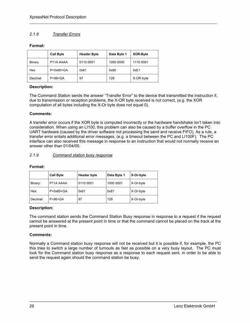
XpressNet Protocol Description __________________________________________________________________________________
__________________________________________________________________________________ 29 Lenz Elektronik GmbH
2.1.8 Transfer Errors
Format:
Call Byte Header Byte Data Byte 1 XOR-Byte
Binary P11A AAAA 0110 0001 1000 0000 1110 0001
Hex P+0x60+GA 0x61 0x80 0xE1
Decimal P+96+GA 97 128 X-OR-byte
Description:
The Command Station sends the answer “Transfer Error” to the device that transmitted the instruction if, due to transmission or reception problems, the X-OR byte received is not correct, (e.g. the XOR computation of all bytes including the X-Or byte does not equal 0).
Comments:
A transfer error occurs if the XOR byte is computed incorrectly or the hardware handshake isn’t taken into consideration. When using an LI100, this problem can also be caused by a buffer overflow in the PC UART hardware (caused by the driver software not processing the send and receive FIFO). As a rule, a transfer error entails additional error messages, (e.g. a timeout between the PC and LI100F). The PC interface can also received this message in response to an instruction that would not normally receive an answer other than 01/04/05.
2.1.9 Command station busy response
Format:
Call Byte Header byte Data Byte 1 X-Or-byte
Binary: P11A AAAA 0110 0001 1000 0001 X-Or-byte
Hex: P+0x60+GA 0x61 0x81 X-Or-byte
Decimal: P+96+GA 97 129 X-Or-byte
Description:
The command station sends the Command Station Busy response in response to a request if the request cannot be answered at the present point in time or that the command cannot be placed on the track at the present point in time.
Comments:
Normally a Command station busy response will not be received but it is possible if, for example, the PC this tries to switch a large number of turnouts as fast as possible on a very busy layout. The PC must look for the Command station busy response as a response to each request sent, in order to be able to send the request again should the command station be busy.
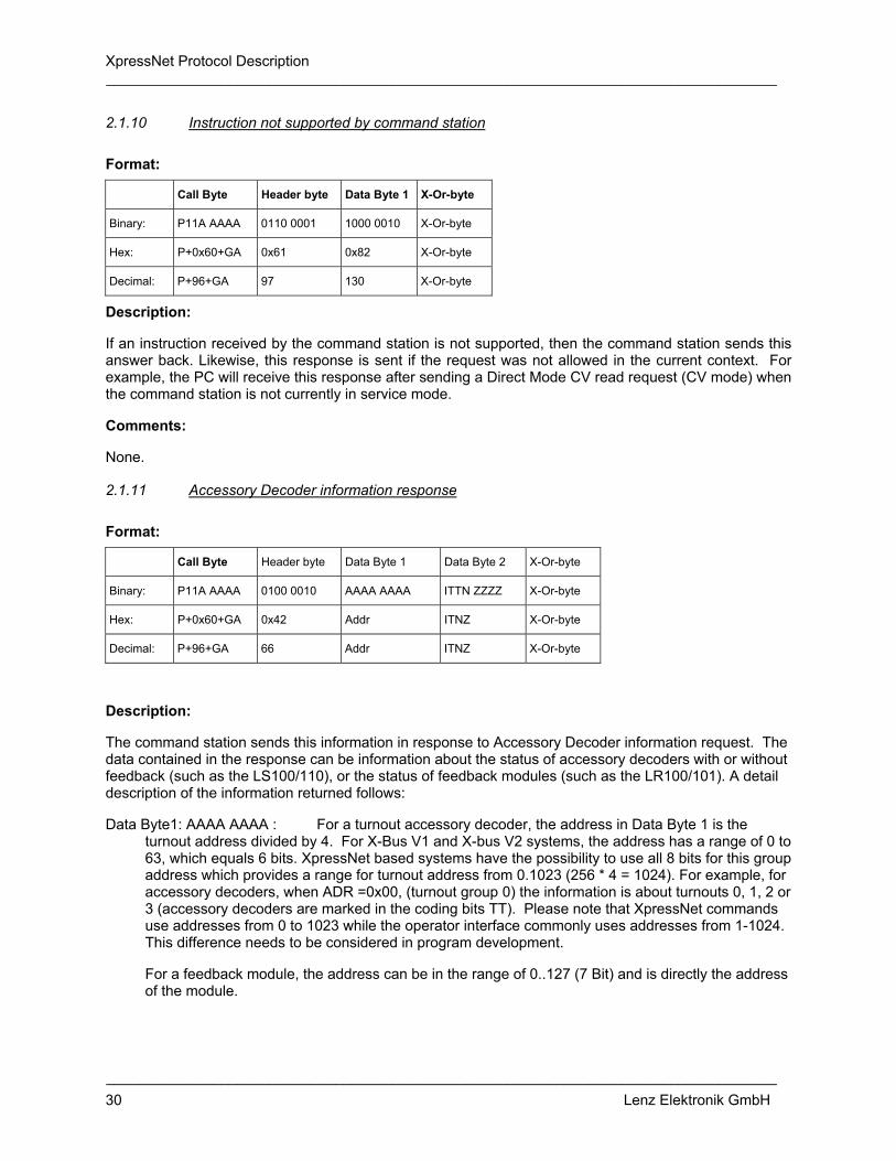
XpressNet Protocol Description __________________________________________________________________________________
__________________________________________________________________________________ 30 Lenz Elektronik GmbH
2.1.10 Instruction not supported by command station
Format:
Call Byte Header byte Data Byte 1 X-Or-byte
Binary: P11A AAAA 0110 0001 1000 0010 X-Or-byte
Hex: P+0x60+GA 0x61 0x82 X-Or-byte
Decimal: P+96+GA 97 130 X-Or-byte
Description:
If an instruction received by the command station is not supported, then the command station sends this answer back. Likewise, this response is sent if the request was not allowed in the current context. For example, the PC will receive this response after sending a Direct Mode CV read request (CV mode) when the command station is not currently in service mode.
Comments:
None.
2.1.11 Accessory Decoder information response
Format:
Call Byte Header byte Data Byte 1 Data Byte 2 X-Or-byte
Binary: P11A AAAA 0100 0010 AAAA AAAA ITTN ZZZZ X-Or-byte
Hex: P+0x60+GA 0x42 Addr ITNZ X-Or-byte
Decimal: P+96+GA 66 Addr ITNZ X-Or-byte
Description:
The command station sends this information in response to Accessory Decoder information request. The data contained in the response can be information about the status of accessory decoders with or without feedback (such as the LS100/110), or the status of feedback modules (such as the LR100/101). A detail description of the information returned follows:
Data Byte1: AAAA AAAA : For a turnout accessory decoder, the address in Data Byte 1 is the turnout address divided by 4. For X-Bus V1 and X-bus V2 systems, the address has a range of 0 to 63, which equals 6 bits. XpressNet based systems have the possibility to use all 8 bits for this group address which provides a range for turnout address from 0.1023 (256 * 4 = 1024). For example, for accessory decoders, when ADR =0x00, (turnout group 0) the information is about turnouts 0, 1, 2 or 3 (accessory decoders are marked in the coding bits TT). Please note that XpressNet commands use addresses from 0 to 1023 while the operator interface commonly uses addresses from 1-1024. This difference needs to be considered in program development.
For a feedback module, the address can be in the range of 0..127 (7 Bit) and is directly the address of the module.

XpressNet Protocol Description __________________________________________________________________________________
__________________________________________________________________________________ 31 Lenz Elektronik GmbH
Data Byte 2: I If this bit is 1, the switching command requested has not been completed and the turnout has not reached its end position.
For feedback modules this bit will always be 0 because the inputs of these modules can become only be 0 or 1.
Data 2: TT This is the coding of the type of requested address:
TT = 0 0 : Address is accessory decoder without feedback
TT = 0 1 : Address is accessory decoder with feedback
TT = 1 0 : Address is a feedback module
TT = 1 1 : reserved for future use
Data 2: N This bit describes which nibble of a turnout or feedback module this response describes. N=0 is the lower nibble, N=1 the upper nibble. For example, for turnout group 0, if N=1 then the status flags (Z3-Z0) contain the status of turnouts 0 and 1. If N=1 the status of turnouts 3 and 4 are provided. For a feedback module the lower nibble contains status for the 4 lower feedback inputs, the upper nibble contains status of the 4 higher feedback inputs. To access all 8 inputs of a feedback module you need to request the information twice, once for the lower nibble, and once for the upper nibble. Please note that the nibble bits are only correct, if a turnout was switched during the current operating session.
Data 3: Z3 Z2 Z1 Z0 Definitions for the status flags
In the case of a turnout accessory decoder: Z1 and Z0 represent the status of the first turnout in the nibble, Z3 and Z2 represent the status of the second turnout in the nibble.
Possible combinations:
Z1 Z0 (the first turnout in the nibble)
0 0 turnout has not been controlled during this operating session.
0 1 last command sent was „0“, turnout „left“.
This is only relative.
1 0 last command sent command was „1“
1 1 invalid combination - both end switches of a
Turnout with feedback are indicating that they are active.
The same structure is used for Z3 and Z2, the second turnout in the nibble. For a feedback module, the 4 bits Z3 toZ0 directly represent the value of the 4 inputs of the requested nibble.
Comments:
None.

XpressNet Protocol Description __________________________________________________________________________________
__________________________________________________________________________________ 32 Lenz Elektronik GmbH
2.1.12 Locomotive information response (X-Bus V1)
One obtains this locomotive information in response to a locomotive request to the command station as described under section 2.2.19.1. X-Bus V1 only supports 14-speed step mode and thus does not need the "ModSel" byte. If another X-Bus device takes over control of a locomotive, the information Locomotive is being operated by another device is sent unrequested to the X-Bus device, which is currently controlling the locomotive. Therefore, all X-Bus devices should have a routine for the purpose to make the user aware of the fact that control of this locomotive was just taken over by another X-Bus device.
2.1.12.1 Locomotive is available for operation
If no other X-Bus device is currently controlling the locomotive, for which the information is being requested, then one obtains the following information with the header byte "locomotive available" as a response to a request for locomotive information.
Format:
Call Byte Header byte Data Byte 1 Data Byte 2 Data Byte 3 X-Or-byte
Binary: P11A AAAA 1000 0011 Locomotive address Locomotive Data Byte 1
Locomotive Data Byte 2
X-Or-byte
Hex: P+0x60+GA 0x83 Locomotive address Locomotive Data Byte 1
Locomotive Data Byte 2
X-Or-byte
Decimal: P+96+GA 131 Locomotive address Locomotive Data Byte 1
Locomotive Data Byte 2
X-Or-byte
Description:
Locomotive Address: An address within the range of values 0 - 99 dec. = 0 - 0x63. The address 0 designates a non-decoder-equipped locomotive.
Locomotive Data Byte 1:
• Bit 7: B7=1:future use: Locomotive being operated by another X-Bus device
B7=0: future use: Locomotive is not currently being operated by any X-Bus device
Note bit7 is not currently being used, the header byte is used to be recognized whether the locomotive is available or is being controlled by another X-Bus device!
• Bit 6: B6=1: last direction command was forward
B6=0: last direction command was reverse
• Bit 5: B5=1: Function 0 is switched on
B5=0: Function 0 is switched off
• Bit 4: not used, always 0.

XpressNet Protocol Description __________________________________________________________________________________
__________________________________________________________________________________ 33 Lenz Elektronik GmbH
• Bit3 to Bit0 provides the locomotives current speed:
• Bit3 • Bit2 • Bit1 • Bit0 • Meaning
• 0 • 0 • 0 • 0 • Speed Step 0
• 0 • 0 • 0 • 1 • Emergency Stop
• 0 • 0 • 1 • 0 • Speed Step 1
• ... • ... • ... • ... • ...
• 1 • 1 • 1 • 1 • Speed Step 14
Locomotive Data Byte 2:
• Bit7 to Bit4: not defined
• Bit3: Status of function 4, "0" = off, " 1" = on
• Bit2: Status of function 3, "0" = off, " 1" = on
• Bit1: Status of function 2, "0" = off, " 1" = on
• Bit0: Status of function 1, "0" = off, " 1" = on
Comments:
None.
2.1.12.2 Locomotive is being operated by another device
If the inquired locomotive is currently being controlled by another X-Bus device, then this response is provided. The contents of the header byte differentiates this from the Locomotive is available for operation response. This response can also be received unrequested, if another X-Bus device took over control of this locomotive.
Format:
Call Byte Header byte Data Byte 1 Data Byte 2 Data Byte 3 X-Or-byte
Binary: P11A AAAA 1010 0011 Locomotive address Locomotive Data Byte 1
Locomotive Data Byte 2
X-Or-byte
Hex: P+0x60+GA 0xA3 Locomotive address Locomotive Data Byte 1
Locomotive Data Byte 2
X-Or-byte
Decimal:
P+96+GA 163 Locomotive address Locomotive Data Byte 1
Locomotive Data Byte 2
X-Or-byte
Description:
Locomotive address, locomotive Data Byte 1 and locomotive Data Byte 2 described the format as under 2.1.12.1.
Comments:
The information "Locomotive is being operated by another device" can be received unrequested if another X-Bus device takes control of the locomotive.

XpressNet Protocol Description __________________________________________________________________________________
__________________________________________________________________________________ 34 Lenz Elektronik GmbH
2.1.13 Locomotive information response (X-Bus V2)
The locomotive information response is provided as an answer to the Locomotive information requests (X-Bus V1 and V2) as described in section 2.2.19.2. Starting with version 2.0 of the command station multiple speed step modes were supported (14, 27 and 28 speed steps). This required the locomotive information response to be extended by one byte "ModSel" (mode SELECT). This byte contains only the coding of the speed step information of the inquired locomotive.
If another X-Bus device issues a locomotive operation request for this locomotive address, the response "Locomotive is being operated by another device" is sent unrequested to the X-Bus device that was previously operating the locomotive. An appropriate operator interface response should be provided in order make the user aware of the fact that control of this locomotive was just taken over by another device.
2.1.13.1 Locomotive is available for operation
If the locomotive is not currently being controlled by another XpressNet device the following locomotive information is provided in response to a "Locomotive information requests (X-Bus V1 and V2).
Format:
Call Byte Header byte Data Byte 1 Data Byte 2 Data Byte 3 Data Byte 4 X-Or-byte
Binary: P11A AAAA 1000 0100 Locomotive address
Locomotive Data Byte 1
Locomotive Data Byte 2
ModSel X-Or-byte
Hex: P+0x60+GA 0x84 Locomotive address
Locomotive Data Byte 1
Locomotive Data Byte 2
ModSel X-Or-byte
Decimal:
P+96+GA 132 Locomotive address
Locomotive Data Byte 1
Locomotive Data Byte 2
ModSel X-Or-byte
Description:
Locomotive Address: A value within the range of 0 to 99 dec. = 0 to 0x63 hex. The address 0 designates a non-decoder equipped conventional locomotive.
ModSel: Contains the current speed step mode for the locomotive:
Depending upon contents of ModSel, locomotive Data Byte 1 has different meanings.
Bit7 to Bit2: not used.
Bit 1 Bit 0 Meaning
0 0 14 speed step mode
0 1 27 speed step mode
1 0 28 speed step mode
1 1 reserved
Locomotive Data Byte 1 Depends on the contents of ModSel
1. ModSel = xxxxxx00 14 Speed Step Mode
Locomotive Data Byte 1 and Locomotive Data Byte 2 are as described in section 2.1.12.1.

XpressNet Protocol Description __________________________________________________________________________________
__________________________________________________________________________________ 35 Lenz Elektronik GmbH
2. ModSel = xxxxxx01 27 drive position mode
Locomotive Data Byte 1:
• Bit 7: B7=1: planned: Locomotive being operated by another X-Bus device
B7=0: planned: Locomotive is not currently being operated by any X-Bus device
Note bit7 is not currently being used, the header byte is used to be recognized whether the locomotive is available or is being controlled by another X-Bus device!
• Bit 6: B6=1: last direction command was forward
B6=0: last direction command was reverse
• Bit 5: B5=1: Function 0 is switched on
B5=0: Function 0 is switched off
• Bit4 to Bit0 provides the locomotives current speed: Note that Bit4 is the LSB of the locomotive's speed.
Bit 3 Bit 2 Bit 1 Bit 0 Bit4 (!) Meaning
0 0 0 0 0 Locomotive stopped
0 0 0 0 1 not used
0 0 0 1 0 Emergency Stop
0 0 0 1 1 not used
0 0 1 0 0 Speed Step 1
0 0 1 0 1 Speed Step 2
0 0 1 1 0 Speed Step 3
... ... ... ... ... ...
1 1 1 1 0 Speed Step 27
3. ModSel = xxxxxx10 28 drive position mode
Locomotive Data Byte 1:
• Bit 7: B7=1: planned: Locomotive being operated by another X-Bus device
B7=0: planned: Locomotive is not currently being operated by any X-Bus device
Note bit7 is not currently being used, the header byte is used to be recognized whether the locomotive is available or is being controlled by another X-Bus device!
• Bit 6: B6=1: last direction command was forward
B6=0: last direction command was reverse
• Bit 5: B5=1: Function 0 is switched on
B5=0: Function 0 is switched off

XpressNet Protocol Description __________________________________________________________________________________
__________________________________________________________________________________ 36 Lenz Elektronik GmbH
Bits 4 to 0 provides the locomotives current speed: Note that Bit 4 is the LSB of the locomotive's speed.
Bit 3 Bit 2 Bit 1 Bit 0 Bit 4 (!) Meaning
0 0 0 0 0 Locomotive Stopped
0 0 0 0 1 not used!
0 0 0 1 0 Emergency Stop
0 0 0 1 1 not used!
0 0 1 0 0 Speed Step 1
0 0 1 0 1 Speed Step 2
0 0 1 1 0 Speed Step 3
. . . . .
1 1 1 1 0 Speed Step 27
1 1 1 1 1 Speed Step 28
Locomotive Data Byte 2: as described in section 2.1.12.1
Comments:
None.
2.1.13.2 Locomotive is being operated by another device
If the inquired locomotive is currently being controlled by another X-Bus device, then this response is provided. It differs from the Locomotive is available for operation response by a difference in the header byte. This response is also sent unrequested, to the X-Bus device that is currently controlling the locomotive.
Format:
Call Byte Header byte Data Byte 1 Data Byte 2 Data Byte 3 Data Byte 4 X-Or-byte
Binary: P11A AAAA 1010 0100 Locomotive address
Locomotive Data Byte 1
Locomotive Data Byte 2
ModSel X-Or-byte
Hex: P+0x60+GA 0xA4 Locomotive address
Locomotive Data Byte 1
Locomotive Data Byte 2
ModSel X-Or-byte
Decimal:
P+96+GA 164 Locomotive address
Locomotive Data Byte 1
Locomotive Data Byte 2
ModSel X-Or-byte
Description:
Locomotive address, locomotive Data Byte 1 and locomotive Data Byte 2 described the format as under 2.1.13.1.
Comments:
The information "Locomotive is being operated by another device" can be received unrequested if another X-Bus device takes control of the locomotive.

XpressNet Protocol Description __________________________________________________________________________________
__________________________________________________________________________________ 37 Lenz Elektronik GmbH
2.1.14 Locomotive information response (XpressNet only)
The locomotive information response is provided in response to the general Locomotive information requests (XpressNet only) (see 2.2.19.3). There are four possible responses depending on the current operating mode of the decoder. Contrary to earlier versions the information on whether or not a locomotive is currently being operated by another network device is contained in the response. Unlike previous versions, if a locomotive is taken over by another XpressNet equipment, then this is communicated to the device that was controlling the locomotive in a separate command (see section 2.1.15). In addition, a new identification byte is inserted after the header byte, which serves to distinguish the different operating modes that became available in XpressNet (such as multi-unit consist control). Because the specific locomotive address that the response deals with is identical to the preceded request for locomotive information, the inquired locomotive address is no longer contained in the response.
2.1.14.1 Locomotive information normal locomotive
This response is sent in response to a Locomotive information requests (XpressNet only) whenever the inquired locomotive is not in either a Double Header or a Multi-Unit maintained by the command station.
Format:
Call Byte Header byte Identification Speed Byte Function A Function B X-Or-byte
Binary: P11A AAAA 1110 0100 0000 BFFF RVVV VVVV 000F FFFF FFFF FFFF X-Or-byte
Hex: P+0x60+GA 0xE4 Identification Speed FA FB X-Or-byte
Decimal: P+96+GA 228 Identification Speed FA FB X-Or-byte
Description:
Identification Byte: Provides the speed step mode and locomotive in use indication
Bit3: B=0: Locomotive is free B=1: Locomotive is being controlled by another XpressNet Device
Bits 0-2: FFF Identification of the current speed step mode being used
Bit 2 Bit 1 Bit 0 Meaning
0 0 0 14 speed step
0 0 1 27 speed step
0 1 0 28 speed step
1 0 0 128 speed step
Speed Byte: Provides the current speed and direction information for the decoder
. Bit 7 R=1: forward direction, R=0: reverse direction.
Bits 0-6 Actual speed of locomotive for 14 speed step mode the bits 0-3 are used as specified in section 2.1.8.1. for 27 speed step mode the bits 0-4 are used as specified in section 2.1.9.1. for 28 speed step mode the bits 0-4 are used as specified in section 2.1.9.1:

XpressNet Protocol Description __________________________________________________________________________________
__________________________________________________________________________________ 38 Lenz Elektronik GmbH
for 128 speed step mode the bits 0-6 are used as follows:
Bit 6 Bit 5 Bit 4 Bit 3 Bit 2 Bit 1 Bit 0 Meaning
0 0 0 0 0 0 0 Speed Step 0
0 0 0 0 0 0 1 Emergency stop
0 0 0 0 0 1 0 Speed Step 1
0 0 0 0 0 1 1 Speed Step 2
... .... .... .... .... .... .... ...
1 1 1 1 1 1 1 Speed Step 126
Function Byte A: status of the functions 0 to 4. 0 0 0 F0 F4 F3 F2 F1
Function Byte B: status of the functions 5 to 12 F12 F11 F10 F9 F8 F7 F6 F5
a value of "1" in a function position indicates that that function is on
Comments:
None.
2.1.14.2 Locomotive information for a locomotive in a multi-unit
This response is sent in response to a Locomotive information requests (XpressNet only) whenever the inquired locomotive is a member of a Multi-Unit maintained by the command station.
Format:
Call Byte Header byte Identification Speed Byte Function A Function B Data Byte 4 X-Or-byte
Binary: P11A AAAA 1110 0101 0001 BFFF RVVV VVVV 000F FFFF FFFF FFFF MTR X-Or-byte
Hex: P+0x60+GA 0xE5 Identification Speed FA FB MTR X-Or-byte
Decimal: P+96+GA 229 Identification Speed FA FB MTR X-Or-byte
Description:
Identification Byte: Bits 0-3 indicate the speed step mode of the locomotive requested and whether it is being controlled by another XpressNet device or not as described in section 2.1.14.1. Note: the speed step mode for a decoder can be different than the speed step mode for the entire multi-unit consist.
Speed Byte: As described under section 2.1.14.1. The speed indicates the speed of the inquired locomotive and not the Multi-unit!
Function A, Function B Bytes: as described under section 2.1.14.1.
MTR: This is the Multi-Unit address of the inquired locomotive. It can have a value of between 1 and 99.
Comments:
Since not all command stations allow for speed and direction commands to be sent to individual locomotives within a consist, speed and direction commands should be sent to the Multi-Unit address and not the locomotive address. Function instructions are to be sent to the locomotive address.

XpressNet Protocol Description __________________________________________________________________________________
__________________________________________________________________________________ 39 Lenz Elektronik GmbH
2.1.14.3 Locomotive information for the Multi-unit address
This response is sent in response to a Locomotive information requests (XpressNet only) whenever the inquired address is a Multi-Unit address maintained by the command station.
Format:
Call Byte Header byte Identification Speed Byte X-Or-byte
Binary: P11A AAAA 1110 0010 0010 BFFF RVVV VVVV X-Or-byte
Hex: P+0x60+GA 0xE2 Identification Speed X-Or-byte
Decimal: P+96+GA 226 Identification Speed X-Or-byte
Description:
Identification Byte: Bits 0-3 indicate the speed step mode of the multi-unit requested and whether it is being controlled by another XpressNet device or not as described in section 2.1.14.1.
Speed Byte: The speed byte is coded as described under 2.1.14.1. The speed reported is the speed of the Multi-unit.
Comments:
No function instructions can currently be sent to the multi-unit address.
2.1.14.4 Locomotive information for a locomotive in a Double Header
This response is sent in response to a Locomotive information requests (XpressNet only) whenever the inquired locomotive is in a Double Header maintained by the command station.
Format:
Call Byte Header byte
Identifi- cation
Speed Byte Function A Function B AH Byte AL Byte X-Or-byte
Binary: P11A AAAA 1110 0110 0110 BFFF RVVV VVVV 000F FFFF FFFF FFFF Addr High Addr Low X-Or-byte
Hex: P+0x60+GA 0xE6 Identification Speed F0 F1 AH AL X-Or-byte
Decimal: P+96+GA 230 Identification Speed F0 F1 AH AL X-Or-byte
Description:
Identification Byte: Bits 0-3 indicate the speed step mode of the locomotive requested and whether it is being controlled by another XpressNet device or not as described in section 2.1.14.1. Note: the speed step mode for an inquired locomotive can be different than the speed step mode for the other locomotive in a Double Header.
Speed Byte: As described under section 2.1.14.1. The speed indicates the speed of the inquired locomotive and not the Double Header!
Function A, Function B Bytes: as described under section 2.1.14.1.
AH Byte: Highbyte of the second locomotive address of the Double Header.
AL Byte: Lowbyte of the second locomotive address of the Double Header

XpressNet Protocol Description __________________________________________________________________________________
__________________________________________________________________________________ 40 Lenz Elektronik GmbH
For locomotive addresses less than 100
Highbyte of the locomotive address is 0x00
Lowbyte of the locomotive address is 0x00 to 0x63
For locomotive address from 100 to 9999:
Highbyte of the locomotive address is: AH = (ADR&0xFF00)+0xC000
Lowbyte of the locomotive address is: AL= (ADR&0x00FF)
Comments:
This response is only provided if the locomotive is currently in a Double Header and the XpressNet locomotive information request was sent as described in section 2.2.19.3.
2.1.15 Locomotive is being operated by another device response (XpressNet only)
This response is sent unrequsted to the XpressNet device that had control of a locomotive prior to another XpressNet device taking control using a Locomotive operations request.
Format:
Call Byte Header byte Identification Data Byte 1 Data Byte 2 X-Or-byte
Binary: P11A AAAA 1110 0011 0100 0000 Address High Address Low X-Or-byte
Hex: P+0x60+GA 0xE3 0x40 AH AL X-Or-byte
Decimal: P+96+GA 227 64 AH AL X-Or-byte
Description:
AH: High byte of the locomotive address.
AL: Low byte of the locomotive address.
For locomotive addresses in the range from 0 to 99:
AH of the locomotive address is 0x00
AL of the locomotive address is 0x00 to 0x63
For locomotive addresses in the range from 100 to 9999:
AH = (ADR&0xFF00)+0xC000
AL= (ADR&0x00FF)
Comments:
This information comes always unrequested, if another XpressNet device took over control of this locomotive
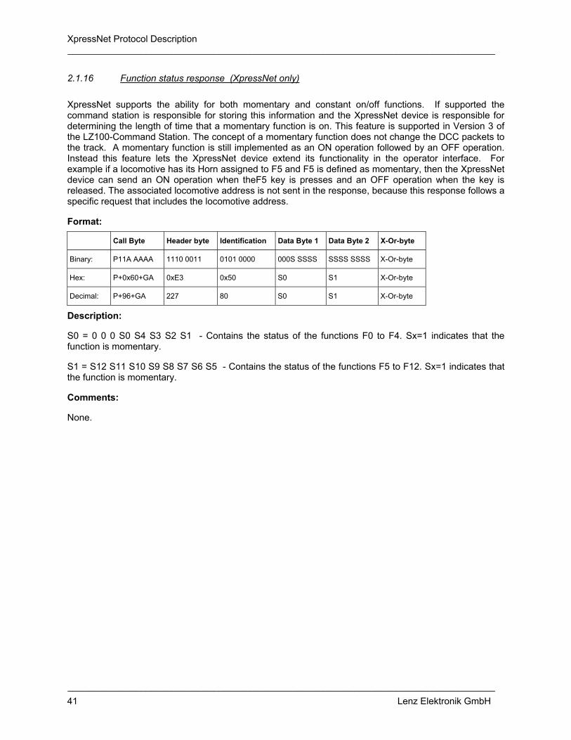
XpressNet Protocol Description __________________________________________________________________________________
__________________________________________________________________________________ 41 Lenz Elektronik GmbH
2.1.16 Function status response (XpressNet only)
XpressNet supports the ability for both momentary and constant on/off functions. If supported the command station is responsible for storing this information and the XpressNet device is responsible for determining the length of time that a momentary function is on. This feature is supported in Version 3 of the LZ100-Command Station. The concept of a momentary function does not change the DCC packets to the track. A momentary function is still implemented as an ON operation followed by an OFF operation. Instead this feature lets the XpressNet device extend its functionality in the operator interface. For example if a locomotive has its Horn assigned to F5 and F5 is defined as momentary, then the XpressNet device can send an ON operation when theF5 key is presses and an OFF operation when the key is released. The associated locomotive address is not sent in the response, because this response follows a specific request that includes the locomotive address.
Format:
Call Byte Header byte Identification Data Byte 1 Data Byte 2 X-Or-byte
Binary: P11A AAAA 1110 0011 0101 0000 000S SSSS SSSS SSSS X-Or-byte
Hex: P+0x60+GA 0xE3 0x50 S0 S1 X-Or-byte
Decimal: P+96+GA 227 80 S0 S1 X-Or-byte
Description:
S0 = 0 0 0 S0 S4 S3 S2 S1 - Contains the status of the functions F0 to F4. Sx=1 indicates that the function is momentary.
S1 = S12 S11 S10 S9 S8 S7 S6 S5 - Contains the status of the functions F5 to F12. Sx=1 indicates that the function is momentary.
Comments:
None.
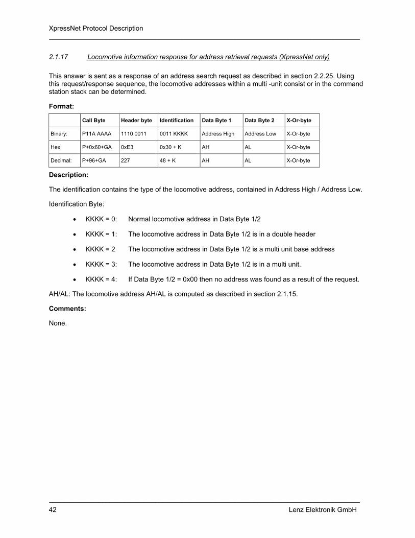
XpressNet Protocol Description __________________________________________________________________________________
__________________________________________________________________________________ 42 Lenz Elektronik GmbH
2.1.17 Locomotive information response for address retrieval requests (XpressNet only)
This answer is sent as a response of an address search request as described in section 2.2.25. Using this request/response sequence, the locomotive addresses within a multi -unit consist or in the command station stack can be determined.
Format:
Call Byte Header byte Identification Data Byte 1 Data Byte 2 X-Or-byte
Binary: P11A AAAA 1110 0011 0011 KKKK Address High Address Low X-Or-byte
Hex: P+0x60+GA 0xE3 0x30 + K AH AL X-Or-byte
Decimal: P+96+GA 227 48 + K AH AL X-Or-byte
Description:
The identification contains the type of the locomotive address, contained in Address High / Address Low.
Identification Byte:
• KKKK = 0: Normal locomotive address in Data Byte 1/2
• KKKK = 1: The locomotive address in Data Byte 1/2 is in a double header
• KKKK = 2 The locomotive address in Data Byte 1/2 is a multi unit base address
• KKKK = 3: The locomotive address in Data Byte 1/2 is in a multi unit.
• KKKK = 4: If Data Byte 1/2 = 0x00 then no address was found as a result of the request.
AH/AL: The locomotive address AH/AL is computed as described in section 2.1.15.
Comments:
None.

XpressNet Protocol Description __________________________________________________________________________________
__________________________________________________________________________________ 43 Lenz Elektronik GmbH
2.1.18 Double Header information response (X-Bus V1)
The Double Header information response is provided in response to the Locomotive information requests (X-Bus V1) (see 2.2.19.1). X-Bus V1 only supports 14 speed step mode so there is no need for the "ModSel" byte. The Double Header occupied response is sent unrequested to the device that was operating the DH before control was taken over by a different device.
2.1.18.1 Double Header available
If the locomotive being requested is not being operated by any other X-Bus device and is currently in a double header, then one obtains the following information in response to a Locomotive information requests (X-Bus V1).
Format:
Call Byte Header byte Data Byte 1 Data Byte 2 Data Byte 3 Data Byte 4 Data Byte 5 X-Or-byte
Binary: P11A AAAA 1100 0101 0000 0100 Locomotive address 1
Locomotive Data Byte 1
Locomotive Data Byte 2
Locomotive address 2
X-Or-byte
Hex: P+0x60+GA 0xC5 0x04 Locomotive address 1
Locomotive Data Byte 1
Locomotive Data Byte 2
Locomotive address 2
X-Or-byte
Decimal: P+96+GA 197 4 Locomotive address 1
Locomotive address 2
locomotive Data Byte 2
Locomotive address 2
X-Or-byte
Description:
Locomotive address 1, Locomotive Data Byte 1, Locomotive Data Byte 2 and Locomotive address 2 are coded as described in section 2.1.12.1.
Comments:
XpressNet does not support commands without the "ModSel" byte. In X-Bus V2 this response is only send as a result of a request that does not use the "ModSel" option. A X-Bus V2 request for operation of a Double Header which was assembled using the X-Bus V1 format will result in a Locomotive information response (X-Bus V2) which allows the use of the new X-Bus V2 speed commands.

XpressNet Protocol Description __________________________________________________________________________________
__________________________________________________________________________________ 44 Lenz Elektronik GmbH
2.1.18.2 Double Header occupied
Format:
Call Byte Header byte Data Byte 1 Data Byte 2 Data Byte 3 Data Byte 4 Data Byte 5 X-Or-byte
Binary: P11A AAAA 1100 0101 0000 0101 Locomotive address 1
Locomotive Data Byte 1
Locomotive Data Byte 2
Locomotive address 2
X-Or-byte
Hex: P+0x60+GA 0xC5 0x05 Locomotive address 1
Locomotive Data Byte 1
Locomotive Data Byte 2
Locomotive address 2
X-Or-byte
Decimal: P+96+GA 197 5 Locomotive address 1
Locomotive Data Byte 1
Locomotive Data Byte 2
Locomotive address 2
X-Or-byte
Description:
Locomotive address 1, locomotive Data Byte 1, locomotive Data Byte 2 and locomotive address 2 are coded as described in section 2.1.12.1.
Comments:
The information can be received by X-Bus equipment unrequested.
2.1.19 Double Header information response (X-Bus V2)
The Double Header information response (X-Bus V2) is sent as a result of a locomotive request as described in section 2.2.19.2. Because of the possibility that the decoder is operating in 14, 27 or 28 speed steps, the "ModSel" byte is included in this response. The information "Double Header occupied" is sent unrequested to the equipment, which was controlling the locomotive before another device took over control.

XpressNet Protocol Description __________________________________________________________________________________
__________________________________________________________________________________ 45 Lenz Elektronik GmbH
2.1.19.1 Double Header available
If the locomotive being requested is not being operated by any other X-Bus device and is currently in a double header, then one obtains the following information in response to a Locomotive information requests (X-Bus V1 and V2).
Format:
Call Byte Header byte Data Byte 1 Data Byte 2 Data Byte 3 Data Byte 4 Data Byte 5 Data Byte 6 X-Or-byte
Binary: P11A AAAA 1100 0110 0000 0100 Locomotive address 1
Locomotive Data Byte 1
Locomotive Data Byte 2
Locomotive address 2
ModSel X-Or-byte
Hex: P+0x60+GA 0xC6 0x04 Locomotive address 1
Locomotive Data Byte 1
Locomotive Data Byte 2
Locomotive address 2
ModSel X-Or-byte
Decimal: P+96+GA 198 4 Locomotive address 1
Locomotive Data Byte 1
Locomotive Data Byte 2
Locomotive address 2
ModSel X-Or-byte
Description:
Locomotive address 1, locomotive Data Byte 1, locomotive Data Byte 2, locomotive address 2 and ModSel are coded as described in section 2.1.13.1.
Comments:
Double header information in this format is only sent to devices which request information in the old X-Bus V2 format that includes the "ModSel" byte. A XpressNet request for operation of a Double Header which was assembled using the X-Bus V2 format will result in a Locomotive information response (XpressNet only) which allows the use of the new XpressNet speed commands.
In XpressNet 4.0 the older speed and direction commands will longer be supported.
2.1.19.2 Double Header occupied
Format:
Call Byte Header byte Data Byte 1 Data Byte 2 Data Byte 3 Data Byte 4 Data Byte 5 Data Byte 6 X-Or-byte
Binary: P11A AAAA 1100 0110 0000 0101 Locomotive address. 1
Loco data 1
Loco data 2
Locomotive address. 2
ModSel X-Or-byte
Hex: P+0x60+GA 0xC6 0x05 Address 1 Loco data 1
Loco data 2
Address 2 ModSel X-Or-byte
Decimal: P+96+GA 198 5 Address 1 Loco data 1
Loco data 2
Address 2 ModSel X-Or-byte
Description:
Locomotive address 1, locomotive Data Byte 1, locomotive Data Byte 2, locomotive address 2 and ModSel are coded as described in section 2.1.13.1.
Comments:
The information "Double Header occupied" can be received by XpressNet equipment unrequested.

XpressNet Protocol Description __________________________________________________________________________________
__________________________________________________________________________________ 46 Lenz Elektronik GmbH
2.1.20 Double Header error response (X-Bus V1 and V2)
A Double Header can only be installed or dissolved, if certain conditions are followed. If these conditions are not met one of the following error messages may be received.
Format:
Call Byte Header byte Data Byte 1 X-Or-byte
Binary: P11A AAAA 0110 0001 1000 0FFF X-Or-byte
Hex: P+0x60+GA 0x61 0x80 + F X-Or-byte
Decimal: P+96+GA 97 128 + F X-Or-byte
Description:
The three error bits (FFF) are coded as follows:
• FFF = 011: One of the locomotives has not been operated by the XpressNet device assembling the Double Header or locomotive 0 was selected.
• FFF = 100: One of the locomotives of the Double Header is being used by another XpressNet device.
• FFF = 101: One of the locomotives is already in another Double Header. • FFF = 110: The speed of one of the locomotives is not zero.
Comments:
If the operations "Establish Double Header" or "Dissolve Double Header" are successful there is no response from the command station. The LI100 announces success to the PC by the release for the next instruction. However if the operation failed, the command station transmits the error message using this response.

XpressNet Protocol Description __________________________________________________________________________________
__________________________________________________________________________________ 47 Lenz Elektronik GmbH
2.1.21 XpressNet MU+DH error message response
Starting from with XpressNet 3.0 errors are summarized in a specific error message response. The error messages transmitted is a result of a specific failure from that preceding request to the command station.
Format:
Call Byte Header byte Identification X-Or-byte
Binary: P11A AAAA 1110 0001 1000 FFFF X-Or-byte
Hex: P+0x60+GA 0xE1 0x80 + F X-Or-byte
Decimal: P+96+GA 225 128 + F X-Or-byte
Description:
The 4 error bits (FFFF) are coded as follows:
• FFFF = 0001: One of the locomotives has not been operated by the XpressNet device assembling the Double Header/Multi Unit or locomotive 0 was selected. .
• FFFF = 0010: One of the locomotives of the Double Header/Multi-Unit is being operated by another XpressNet device.
• FFFF = 0011: One of the locomotives already is in another Multi-Unit or Double Header. • FFFF = 0100: The speed of one of the locomotives of the Double Header/Multi-Unit is not zero. • FFFF = 0101: The locomotive is not in a multi-unit. • FFFF = 0110 The locomotive address is not a multi-unit base address. • FFFF = 0111: It is not possible to delete the locomotive. • FFFF = 1000: The command station stack is full
Comments:
None

XpressNet Protocol Description __________________________________________________________________________________
__________________________________________________________________________________ 48 Lenz Elektronik GmbH
2.2 Data sent from an XpressNet device to the command station
Upon receipt of a “Normal inquiry” (see section 2.1.1), an XpressNet device can begin transmission and make a request e.g. ask for data, control locomotives or execute programming sequences. Depending upon the specific request, the command station may provide the appropriate response to the device. Only one request can be processed after each “Normal inquiry”, i.e. a XpressNet device cannot transmit a locomotive control instruction to the head office and inquire immediately thereafter the status of a locomotive. Before the second request can be transmitter the XpressNet device must receive another “Normal inquiry”. Between a “Normal inquiry” to the same XPressNet device, the command station will likely send a “Normal inquiry” to other XpressNet devices on the Network. Thus is to guarantee that a single device cannot consume the entire bandwidth and that all devices connected to the network are guaranteed a transmission window.
After the LI100 provides the CTS signal (and only then), can the PC initiate communication to control devices (such as locomotives) or request information. Depending on the actual PC requests the LI100 either forwards these requests on to the command station or provides the response itself. If the request results in a needed response from the command station, the command station sends the appropriate response to the LI and the LI forwards this information to the PC. It is important that by the PC strictly utilize the hardware handshake of the serial interface because this is the only means that the LI100 uses to indicate when it is ready to receive communication.
When there is any trouble in receiving something during the time slot the addressed device have to respond the LZ sends a "quit" command to that device immediately. The device now is informed and can make some further decisions.
Note: Not all command stations support all instructions. This must be considered by all XpressNet device including a PC program, in order to avoid continuous loops or improper operation (see also section 2.1.10 Instruction not supported by command station).
If the command station received the request but can not process the command station transmits a “Command station busy response” described in section 2.1.8 or an “Instruction not supported by command station” response described in section 2.1.10 back to the XpressNet device.
2.2.1 Acknowledgement Response
Format:
Header byte X-Or-byte
Binary: 0010 0000 0010 0000
Hex: 0x20 0x20
Decimal: 32 32
Description: If a device receives a “Request Acknowledgement from Device”, then it must answer with this response. The command station will continue to send a “Request Acknowledgement from Device” and will allow no further communications until it receives this answer. Comments:
This transmission is performed by the actual XpressNet device. In the case of a PC connected to an LI100, the LI100 transmits the acknowledgement and not the PC.

XpressNet Protocol Description __________________________________________________________________________________
__________________________________________________________________________________ 49 Lenz Elektronik GmbH
2.2.2 Resume operations request
Format:
Header byte Data Byte 1 X-Or-byte
Binary: 0010 0001 1000 0001 1010 0000
Hex: 0x21 0x81 0xA0
Decimal: 33 129 160
Description:
The instruction tells the command station to turn on power to the track (if it was switched off) and begin transmitting DCC packets to the track. This causes the termination of an emergency stop, an emergency off or the completion of the programming on the programming track (service mode) operations.
Comments:
None.
Response:
Upon completion of this command the command station sends Normal operation resumed as a broadcast message to all XpressNet devices. See section 2.1.4.1.
2.2.3 Stop operations request (emergency off)
Format:
Header byte Data Byte 1 X-Or-byte
Binary: 0010 0001 1000 0000 1010 0001
Hex: 0x21 0x80 0xA1
Decimal: 33 128 161
Description:
This instruction tells the command station to immediately stop sending DCC packets to the track and to switch off the DCC track power.
Comments:
None.
Response:
After turning off the track power, the command station sends Track power Off as a broadcast message several times to all XpressNet devices. See section 2.1.4.2

XpressNet Protocol Description __________________________________________________________________________________
__________________________________________________________________________________ 50 Lenz Elektronik GmbH
2.2.4 Stop all locomotives request (emergency stop)
Format:
Header byte X-Or-byte
Binary: 1000 0000 1000 0000
Hex: 0x80 0x80
Decimal: 128 128
Description:
The instruction instructs the command station to immediately emergency stop all locomotives on the layout. The DCC track power remains switched on, so that turnouts can continue to be controlled.
Comments:
None.
Response:
The command station sends a broadcast of "everything stopped" several times to all network devices and also to the specific XpressNet device that initiated this instruction. See section 2.1.4.3.
2.2.5 Emergency stop a specific locomotive operation
2.2.5.1 Emergency stop a locomotive (X-Bus V1 and V2)
Format:
Header byte Data Byte 1 X-Or-byte
Binary: 1001 0001 Locomotive address X-Or-byte
Hex: 0x91 Locomotive address X-Or-byte
Decimal: 145 Locomotive address X-Or-byte
Description:
The instruction tells the command station to immediately stop only the desired locomotive on the track without its preprogrammed deceleration rate (emergency stop). The DCC track power remains switched on, so that turnouts and all other locomotives can continue to be controlled normally.
Comments:
Locomotive addresses in the range of 0 to 99 are allowed.
Response:
None

XpressNet Protocol Description __________________________________________________________________________________
__________________________________________________________________________________ 51 Lenz Elektronik GmbH
2.2.5.2 Emergency stop a locomotive (XpressNet)
Format:
Header byte Data Byte 1 Data Byte 2 X-Or-byte
Binary: 1001 0010 Address High Address Low X-Or-byte
Hex: 0x92 AH AL X-Or-byte
Decimal: 146 AH AL X-Or-byte
Description:
The instruction tells the command station to immediately stop only the desired locomotive on the track without its preprogrammed deceleration rate (emergency stop). The DCC track power remains switched on, so that turnouts and all other locomotives can continue to be controlled normally.
Comments:
Locomotive addresses in the range of 0 to 99 are allowed.
The locomotive address AH/AL is as specified in section 2.1.14.
Response:
None
2.2.6 Emergency stop selected locomotives (X-Bus V1 and V2)
Format:
Header byte Data Byte 1 .. Data Byte N X-Or-byte
Binary: 1001 NNNN Locomotive address 1 .. Locomotive address N X-Or-byte
Hex: 0x90 + N Locomotive address 1 .. Locomotive address N X-Or-byte
Decimal: 144 + N Locomotive address 1 .. Locomotive address N X-Or-byte
Description:
The instruction tells the command station to immediately stop only the specified locomotives on the track without their preprogrammed deceleration rate (emergency stop). The DCC track power remains switched on, so that turnouts and all other locomotives can continue to be controlled normally.
Comments:
Locomotive addresses in the range of 0 to 99 are allowed.
This request is no longer supported in XpressNet and should be replaced by a sequence of "Emergency stop a locomotive" requests.
Response:
None

XpressNet Protocol Description __________________________________________________________________________________
__________________________________________________________________________________ 52 Lenz Elektronik GmbH
2.2.7 Register Mode read request (Register Mode)
Format:
Header byte Data Byte 1 Data Byte 2 X-Or-byte
Binary: 0010 0010 0001 0001 0000 RRRR X-Or-byte
Hex: 0x22 0x11 R X-Or-byte
Decimal: 34 17 R X-Or-byte
Description:
The request tells the command station to switch into service mode and to read the decoder that is on the programming track using Register Mode. The command station attempts to read the register, which is indicated as 0000 RRRR. Values of 1..8 are allowed.
Comments:
The read instruction does not require an answer by the command station! A result must be specifically requested with the "Request for Service Mode results" request. Only after receiving the response to programming results request can it be determined whether the read instruction was successful or not.
When the command station receives a register read instruction the command station sends the Broadcast "service mode entry" to all network participants which prevents them from sending further instructions. Only the XpressNet device that requested the Command Station enter service mode can continue to send further service mode requests until that device instructs the command station to exit service mode.
Response:
A "service mode entry" broadcast is sent to all XpressNet devices upon the command stations entry to service mode. See section 2.1.4.4
2.2.8 Direct Mode CV read request (CV mode)
Format:
Header byte Data Byte 1 Data Byte 2 X-Or-byte
Binary: 0010 0010 0001 0101 CCCC CCCC X-Or-byte
Hex: 0x22 0x15 CV X-Or-byte
Decimal: 34 21 CV X-Or-byte
Description:
The request tells the command station to switch into service mode and to read the decoder that is on the programming track, using Direct CV Mode. The CV read is specified by the value of CCCC CCCC.
The range is from 1 to 256, CV256 is sent as 00
Comments:
The read instruction does not require an answer by the command station! A result must be specifically requested with the request "programming result". Only after receiving the response to programming results request can it be determined whether the read instruction was successful or not or if the decoder supports Direct CV mode. If the decoder could not be read using Direct CV mode, the command station

XpressNet Protocol Description __________________________________________________________________________________
__________________________________________________________________________________ 53 Lenz Elektronik GmbH
may try register mode. The results of these read actions are provided in response to a "Request for Service Mode results" request. The XpressNet equipment must examine the results to determine which mode was used to read the CV.
When the command station receives a direct CV service mode read instruction the command station sends the Broadcast "service mode entry" to all network participants which prevents them from sending further instructions. Only the XpressNet device that requested the Command Station enter service mode can continue to send further service mode requests until that device instructs the command station to exit service mode.
Response:
A "service mode entry" broadcast is sent to all XpressNet devices upon the command stations entry to service mode. See section 2.1.4.4
2.2.9 Paged Mode read request (Paged Mode)
Format:
Header byte Data Byte 1 Data Byte 2 X-Or-byte
Binary: 0010 0010 0001 0100 CCCC CCCC X-Or-byte
Hex: 0x22 0x14 CV X-Or-byte
Decimal: 34 20 CV X-Or-byte
Description:
This request tells the command station to switch into service mode and to read the decoder that is on the programming track using PAGED mode. It is the responsibility of the command station to make the appropriate conversion of the CV into the page and offset, and to set the page register appropriately before attempting the value of the appropriate register.
The CV read is specified by the value of CCCC CCCC. The range is from 1 to 256, whereby CV256 is to be sent as 00
Comments:
The read instruction does not require an answer by the command station! A result must be specifically requested with the request "programming result". Only after receiving the response to programming results request can it be determined whether the read instruction was successful and if the requested mode way used. The results of these read actions are provided in response to a "Request for Service Mode results" request. The XpressNet equipment must examine the results to determine which mode was used to read the CV.
When the command station receives a paged mode read instruction the command station sends the Broadcast "service mode entry" to all network participants which prevents them from sending further instructions. Only the XpressNet device that requested the Command Station enter service mode can continue to send further service mode requests until that device instructs the command station to exit service mode.
Response:
A "service mode entry" broadcast is sent to all XpressNet devices upon the command stations entry to service mode. See section 2.1.4.4

XpressNet Protocol Description __________________________________________________________________________________
__________________________________________________________________________________ 54 Lenz Elektronik GmbH
2.2.10 Request for Service Mode results
Format:
Header byte Data Byte 1 X-Or-byte
Binary: 0010 0001 0001 0000 0011 0001
Hex: 0x21 0x10 0x31
Decimal: 33 16 49
Description:
The instruction requests the command station to transmit back the result of a proceeding read action to the XpressNet equipment.
Comments:
None.
Response:
The response is described in section 2.1.5.
2.2.11 Register Mode write request (Register Mode)
Format:
Header byte Data Byte 1 Data Byte 2 Data Byte 3 X-Or-byte
Binary: 0010 0011 0001 0010 0000 RRRR Data X-Or-byte
Hex: 0x23 0x12 R Data X-Or-byte
Decimal: 35 18 R Data X-Or-byte
Description:
The service mode instruction tells the command station switch into service mode and to write the specified value (Data Byte 3) into the specified register (Data Byte 2) using Register Mode.
The range of register values is 1 to 8.
Comments:
Before a write instruction is used, the command station should be shifted by a read instruction into the programming mode. There is no control on the part of the XpressNet equipment over it, whether the decoder also understood the programming sequence, except by repeated selection.
Response:
A "service mode entry" broadcast is sent to all XpressNet devices upon the command stations entry to service mode. See section 2.1.4.4

XpressNet Protocol Description __________________________________________________________________________________
__________________________________________________________________________________ 55 Lenz Elektronik GmbH
2.2.12 Direct Mode CV write request (CV mode)
Format:
Header byte Data Byte 1 Data Byte 2 Data Byte 3 X-Or-byte
Binary: 0010 0011 0001 0110 CCCC CCCC Data X-Or-byte
Hex: 0x23 0x16 CV Data X-Or-byte
Decimal: 35 22 CV Data X-Or-byte
Description:
This service mode request tells the command station to switch into service mode and to write the specified value (Data Byte 3) into the specified CV (Data Byte 2) using Direct CV Mode.
The range for CVs is 1-256. CV256 is requested using a value of 0x00 in Data Byte 2.
Comments:
Before a direct mode CV write request is issued, a direct mode CV read instruction should be issued and the service mode results examined in order to determine that the decoder supports Direct Mode. It is the responsibility of the XpressNet device to determine that the decoder supports a specific mode before using that mode.
Response:
A "service mode entry" broadcast is sent to all XpressNet devices upon the command stations entry to service mode. See section 2.1.4.4
2.2.13 Paged Mode write request (Paged mode)
Format:
Header byte Data Byte 1 Data Byte 2 Data Byte 3 X-Or-byte
Binary: 0010 0011 0001 0111 CCCC CCCC Data X-Or-byte
Hex: 0x23 0x17 CV Data X-Or-byte
Decimal: 35 23 CV Data X-Or-byte
Description:
The service mode instruction tells the command station switch into service mode and to write the specified value (Data Byte 3) into the specified CV (Data Byte 2) using Paged Mode. It is the responsibility of the command station to make the appropriate conversion of the CV into the Page and offset, and to set the page register appropriately before setting the value of the desired register.
The CV read is specified by the value of CCCC CCCC. The range for CVs is 1-256. CV256 is requested using a value of 0x00 in Data Byte 2.
Comments:
It is not possible to determine if a decoder supports paged mode. Therefore care must be taken with this mode, as an unexpected result will occur if the decoder does not support paged mode.

XpressNet Protocol Description __________________________________________________________________________________
__________________________________________________________________________________ 56 Lenz Elektronik GmbH
Response:
A "service mode entry" broadcast is sent to all XpressNet devices upon the command stations entry to service mode. See section 2.1.4.4
2.2.14 Command station software-version request
Format:
Header byte Data Byte 1 X-Or-byte
Binary: 0010 0001 0010 0001 0000 0000
Hex: 0x21 0x21 0x00
Decimal: 33 33 0
Description:
This request instructs the command station to respond with its software version number.
Comments:
None.
Response:
The response is described in section 2.1.6.
2.2.15 Command station status request
Format:
Header byte Data Byte 1 X-Or-byte
Binary: 0010 0001 0010 0100 0000 0101
Hex: 0x21 0x24 0x05
Decimal: 33 36 5
Description:
This request instructs the command station to respond with its current status.
Comments:
None.
Response:
The response is described in section 2.1.7.

XpressNet Protocol Description __________________________________________________________________________________
__________________________________________________________________________________ 57 Lenz Elektronik GmbH
2.2.16 Set command station power-up mode
Format:
Header byte Data Byte 1 Data Byte 2 X-Or-byte
Binary: 0010 0010 0010 0010 0000 0M00 X-Or-byte
Hex: 0x22 0x22 M X-Or-byte
Decimal: 34 34 M X-Or-byte
Description:
Sets the starting mode of the command station when it is powered up. M=0: Manual Start Mode - no speed and direction commands are sent to locomotives on power up, M=1: Automatic Start Mode - on power up the command station sends DCC packets to all known locomotives with the last known speed, direction and function status.
Comments:
Not all command stations support this request.
Response:
None
2.2.17 Accessory Decoder information request
Format:
Header byte Data Byte 1 Data Byte 2 X-Or-byte
Binary: 0100 0010 AAAA AAAA 1000 000N X-Or-byte
Hex: 0x42 Address 0x80 + N X-Or-byte
Decimal: 66 Address 128 + N X-Or-byte
Description:
This request instructs the command station to respond with the accessory decoder status.
Address: For a switching decoder, this is the address of the desired output divided by 4 (group address). The range of the group address is 0..63 = 6bit for central unit versions < 3.0.
For version 3.0 and above, all 8 bits are allowed for the group address. So 1024 turnouts can be switched and turnouts 0..512 can have feedback, turnouts 513..1023 can not have feedback.
For a feedback module, the address can be 0..127 and is the module address.
N: Marks the desired nibble. N=0 is the lower nibble, N=1 the upper nibble.
For switching decoders, there are 4 turnouts in one group and the lower nibble marks turnouts 0 and 1 in the group and the upper nibble turnouts 2 and 3.
For a feedback module, in the lower nibble the 4 lower inputs of the module are included and in the upper nibble, the upper 4 inputs.

XpressNet Protocol Description __________________________________________________________________________________
__________________________________________________________________________________ 58 Lenz Elektronik GmbH
Comments:
Example 1: Status of turnout 21 is desired. Address 21 div by 4 = 5. So turnout 21 is in group 5. Turnouts 20,21,22 and 23 are in group 5, so the nibble bit is 0 (lower nibble).
Example 2: Status of turnout 620 is desired. Address 620 div by 4 = 155. So turnout 620 is in group 155. Turnouts 620, 621, 622 and 623 are in group 155, so the nibble bit is 1 (higher nibble).
Response:
The response is described in section 2.1.11.
2.2.18 Accessory Decoder operation request
Format:
Header byte Data Byte 1 Data Byte 2 X-Or-byte
Binary: 0101 0010 AAAA AAAA 1000 DBBD X-Or-byte
Hex: 0x52 Address 0x80 + DBBD X-Or-byte
Decimal: 82 Address 128 + DBBD X-Or-byte
Description:
Switching commands can only be sent to switching decoders. The address is turnout / 4 (group). The offset in the group and which of the 2 outputs has to be activated or deactivated has to be defined. This is done with the bits D1 B1 B0 and D2 in data 2.
B1 and B0: These are the two LSB´s which are the rest of the division by 4. D1: D1 = 0 means activate output. D1 = 1 means deactivate output. D2: D2 = 0 means use output 1 of the selected turnout. D2 = 1 means use output 2 of the selected turnout.
Comments:
Prior to XpressNet only ab decoder address range from 0 to 63 was defined as a valid address. XpressNet allows the full range from 0-255 to be used. Not all command stations support this full range. See also section 2.2.17.
Response:
None

XpressNet Protocol Description __________________________________________________________________________________
__________________________________________________________________________________ 59 Lenz Elektronik GmbH
2.2.19 Locomotive information request
2.2.19.1 Locomotive information requests (X-Bus V1)
Format:
Header byte Data Byte 1 X-Or-byte
Binary: 1010 0001 Locomotive address X-Or-byte
Hex: 0xA1 Locomotive address X-Or-byte
Decimal: 161 Locomotive address X-Or-byte
Description:
14 speed steps was the only mode supported until X-Bus V2. Therefore no additional distinction byte (ModSel) was necessary. A locomotive inquiry with this instruction causes that the command station to respond only with the Locomotive information response (X-Bus V1) since the command station assumes that any device that issues this request does not understand the more advanced modes.
Comments:
Locomotive address is in the range 0 to 99.
Response:
The response is described in section 2.1.12.
2.2.19.2 Locomotive information requests (X-Bus V1 and V2)
Format:
Header byte Data Byte 1 Data Byte 2 X-Or-byte
Binary: 1010 0010 Locomotive address ModSel X-Or-byte
Hex: 0xA2 Locomotive address ModSel X-Or-byte
Decimal: 162 Locomotive address ModSel X-Or-byte
Description:
Starting with X-Bus V2 14,27, and 28 speed step modes are supported. To distinguish the speed step mode the ModSel byte is sent with each request. A command station that supports X-Bus 2.0 is designed to answer with the inclusive ModSel byte so that the network device can determine the speed step mode of the inquired locomotive.
Comments:
Locomotive address is in the range 0 to 99.
Response:
The response is described in section 2.1.13.

XpressNet Protocol Description __________________________________________________________________________________
__________________________________________________________________________________ 60 Lenz Elektronik GmbH
2.2.19.3 Locomotive information requests (XpressNet only)
Format:
Header byte Identification Data Byte 1 Data Byte 2 X-Or-byte
Binary: 1110 0011 0000 0000 Address High Address Low X-Or-byte
Hex: 0xE3 0x00 AH AL X-Or-byte
Decimal: 227 0 AH AL X-Or-byte
Description:
XpressNet provides a much richer response to locomotive information requests. To allow support for the full range of 10,000 locomotive addresses two bytes (AH/AL) are used to specify the address of the locomotive that the request is for. The locomotive address AH/AL is computed as described in section 2.1.15.
Comments:
It is possible to inquire the status of locomotives over the complete range of addressees from 0 to 9999.
Response:
The response is described in section 2.1.14.
2.2.19.4 Function status request (XpressNet only)
Format:
Header byte Identification Data Byte 1 Data Byte 2 X-Or-byte
Binary: 1110 0011 0000 0111 Address High Address Low X-Or-byte
Hex: 0xE3 0x07 AH AL X-Or-byte
Decimal: 227 7 AH AL X-Or-byte
Description:
XpressNet supports the concept of both momentary functions and on/off functions. The command station maintains the status of a function on whether it is momentary or on/off. It is the responsibility of the XpressNet device that is controlling the function to determine the length of a time a momentary function is on. This request is used to ask the command station for the current function status for a particular locomotive address.
To allow support for the full range of 10,000 locomotive addresses two bytes (AH/AL) are used to specify the address of the locomotive that the request is for. The locomotive address AH/AL is computed as described in section 2.1.15.
Comments:
None.
Response:
The current state of functions F0 to F12 as momentary or on/off, as described in section 2.1.16, is provided as a response to this request.

XpressNet Protocol Description __________________________________________________________________________________
__________________________________________________________________________________ 61 Lenz Elektronik GmbH
2.2.20 Locomotive operations request
2.2.20.1 Locomotive operations (X-Bus V1)
Format:
Header byte Data Byte 1 Data Byte 2 Data Byte 3 X-Or-byte
Binary: 1011 0011 Locomotive address Locomotive Data Byte 1
Locomotive Data Byte 2
X-Or-byte
Hex: 0xB3 Locomotive address Locomotive Data Byte 1
Locomotive Data Byte 2
X-Or-byte
Decimal: 179 Locomotive address Locomotive Data Byte 1
Locomotive Data Byte 2
X-Or-byte
Description:
X-Bus V1 only supports 14 speed steps so does not need the (ModSel) byte to distinguish between different speed step modes.
Locomotive Data Byte 1 and locomotive Data Byte 2 are coded as described under 2.1.12.1.
Comments:
Locomotive address is in the range from 0 to 99.
Response:
None.
2.2.20.2 Locomotive operations (X-Bus V2)
Format:
Header byte Data Byte 1 Data Byte 2 Data Byte 3 Data Byte 4 X-Or-byte
Binary: 1011 0100 Locomotive address Locomotive Data Byte 1 Locomotive Data Byte 2 ModSel X-Or-byte
Hex: 0xB4 Locomotive address Locomotive Data Byte 1 Locomotive Data Byte 2 ModSel X-Or-byte
Decimal: 180 Locomotive address Locomotive Data Byte 1 Locomotive Data Byte 2 ModSel X-Or-byte
Description:
X-Bus V2 supports 14, 27 and 28 speed steps. The ModSel byte is used to indicate which speed step mode to use, so that the command station can modulate an appropriate track signal.
Locomotive Data Byte 1, locomotive Data Byte 2 and ModSel are coded as described under 2.1.13.1.
Comments:
Locomotive address is in the range 0 to 99
Response:
None.

XpressNet Protocol Description __________________________________________________________________________________
__________________________________________________________________________________ 62 Lenz Elektronik GmbH
2.2.20.3 Locomotive speed and direction operations (XpressNet only)
XpressNet supports 14, 27, 28 and 128 speed step modes as well as the full 4 digit locomotive address range. To provide room for expansion, the ModSel byte was replaced by the Identification Byte. The speed and direction information for 14, 27 and 28 speed steps is coded as described in section 2.1.13.1. The speed and direction information for 128 speed steps is coded as described in section 2.1.14.1.
Format - Speed and direction instruction for 14 speed steps:
Header byte Identification Data Byte 1 Data Byte 2 Data Byte 3 X-Or-byte
Binary: 1110 0100 0001 0000 Address High Address Low R000 VVVV X-Or-byte
Hex: 0xE4 0x10 AH AL RV X-Or-byte
Decimal: 228 16 AH AL RV X-Or-byte
Format - Speed and direction instruction for 27 speed steps:
Header byte Identification Data Byte 1 Data Byte 2 Data Byte 3 X-Or-byte
Binary: 1110 0100 0001 0001 Address High Address Low R00V VVVV X-Or-byte
Hex: 0xE4 0x11 AH AL RV X-Or-byte
Decimal: 228 17 AH AL RV X-Or-byte
Format - Speed and direction instruction for 28 speed steps:
Header byte Identification Data Byte 1 Data Byte 2 Data Byte 3 X-Or-byte
Binary: 1110 0100 0001 0010 Address High Address Low R00V VVVV X-Or-byte
Hex: 0xE4 0x12 AH AL RV X-Or-byte
Decimal: 228 18 AH AL RV X-Or-byte
Format - Speed and direction instruction for 128 speed steps:
Header byte Identification Data Byte 1 Data Byte 2 Data Byte 3 X-Or-byte
Binary: 1110 0100 0001 0011 Address High Address Low RVVV VVVV X-Or-byte
Hex: 0xE4 0x13 AH AL RV X-Or-byte
Decimal: 228 19 AH AL RV X-Or-byte
Description:
Locomotive Speed and direction operations for XpressNet contain only the speed and direction instructions. Control of the functions is handled separately.
Comments:
Locomotives with addresses 0 to 9999 can be controlled. The locomotive address is specified in AH/AL as specified in section 2.1.15.
Response:
None.

XpressNet Protocol Description __________________________________________________________________________________
__________________________________________________________________________________ 63 Lenz Elektronik GmbH
2.2.20.4 Function operation instructions (XpressNet only)
XpressNet supports all 13 NMRA DCC functions (F0-F12). The function instructions for a locomotive subdivide themselves in 3 different groups, which correspond to the three function types in a DCC packet. These groups are group 1 (F0 to F4), group 2 (F5 to F8) and group 3 (F9 to F12). The specific function group is specified in the identification data byte of the packet.
Format - Function instruction group 1:
Header byte Identification Data Byte 1 Data Byte 2 Data Byte 3 X-Or-byte
Binary: 1110 0100 0010 0000 Address High Address Low 000F FFFF X-Or-byte
Hex: 0xE4 0x20 AH AL Group 1 X-Or-byte
Decimal: 228 32 AH AL Group 1 X-Or-byte
Format - Function instruction group 2:
Header byte Identification Data Byte 1 Data Byte 2 Data Byte 3 X-Or-byte
Binary: 1110 0100 0010 0001 Address High Address Low 0000 FFFF X-Or-byte
Hex: 0xE4 0x21 AH AL Group 2 X-Or-byte
Decimal: 228 33 AH AL Group 2 X-Or-byte
Format - Function instruction group 3:
Header byte Identification Data Byte 1 Data Byte 2 Data Byte 3 X-Or-byte
Binary: 1110 0100 0010 0010 Address High Address Low 0000 FFFF X-Or-byte
Hex: 0xE4 0x22 AH AL Group 3 X-Or-byte
Decimal: 228 34 AH AL Group 3 X-Or-byte
Description:
Data Byte 3 indicated the current status of each function. If Fx=1, then is the function on, otherwise the function is off
Group 1: 0 0 0 F0 F4 F3 F2 F1 Group 2: 0 0 0 0 F8 F7 F6 F5 Group 3: 0 0 0 0 F12 F11 F10 F9
Comments:
Locomotives with addresses 0 to 9999 can be controlled. The locomotive address is specified in AH/AL as specified in section 2.1.15.
Response:
None.

XpressNet Protocol Description __________________________________________________________________________________
__________________________________________________________________________________ 64 Lenz Elektronik GmbH
2.2.20.5 Set function state (XpressNet only)
XpressNet allows functions F0-F12 to be specified as either monetary on constant on/off. Momentary functions are especially useful for sound control. The state of each function for each locomotive is stored in a database maintained by the command station (first implemented in LZ100V3). XpressNet devices can set or query the state of functions for each locomotive. It is up to the XpressNet device to determine the length of time that a momentary function is on. The function will remain on until switched off by the XpressNet device. The functions are grouped into three sets: group 1, group 2, and group 3.
Format - Set Function state group 1:
Header byte Identification Data Byte 1 Data Byte 2 Data Byte 3 X-Or-byte
Binary: 1110 0100 0010 0100 Address High Address Low 000S SSSS X-Or-byte
Hex: 0xE4 0x24 AH AL Group 1 X-Or-byte
Decimal: 228 36 AH AL Group 1 X-Or-byte
Format - Set Function state group 2:
Header byte Identification Data Byte 1 Data Byte 2 Data Byte 3 X-Or-byte
Binary: 1110 0100 0010 0101 Address High Address Low 0000 SSSS X-Or-byte
Hex: 0xE4 0x25 AH AL Group 2 X-Or-byte
Decimal: 228 37 AH AL Group 2 X-Or-byte
Format - Set Function state group 3:
Header byte Identification Data Byte 1 Data Byte 2 Data Byte 3 X-Or-byte
Binary: 1110 0100 0010 0110 Address High Address Low 0000 SSSS X-Or-byte
Hex: 0xE4 0x26 AH AL Group 3 X-Or-byte
Decimal: 228 38 AH AL Group 3 X-Or-byte
Description:
The meanings for SSSS for each group follow:
Data Byte 3 indicated the current state of each function. If Sx=1, then the function is on/off. If Sx=0 then the function id momentary.
• Group 1: 0 0 0 S0 S4 S3 S2 S1 • Group 2: 0 0 0 0 S8 S7 S6 S5 • Group 3: 0 0 0 0 S12 S11 S10 S9
Comments:
Locomotives with addresses 0 to 9999 can be controlled. The locomotive address is specified in AH/AL as specified in section 2.1.15.
Response:
None.

XpressNet Protocol Description __________________________________________________________________________________
__________________________________________________________________________________ 65 Lenz Elektronik GmbH
2.2.21 Double Header operations (X-Bus V1 and V2)
2.2.21.1 Establish Double Header
Format:
Header byte Identification Data Byte 1 Data Byte 2 X-Or-byte
Binary: 1100 0011 0000 0101 Address 1 Address 2 X-Or-byte
Hex: 0xC3 0x05 Address 1 Address 2 X-Or-byte
Decimal: 195 5 Address 1 Address 2 X-Or-byte
Description:
The locomotives in Data Byte 1 and Data Byte 2 are joined in the command station to a Double Header. Once set up, speed and direction commands sent to one of the locomotive addresses are sent to both locomotives by the command station.
Comments:
Locomotives with addresses 1 to 99 can be placed in a double header using this request.
Response:
If this request is not successful, then the command station sends one of the error messages as described in section 2.1.20.
2.2.21.2 Dissolve Double Header
Format:
Header byte Identification Data Byte 1 Data Byte 2 X-Or-byte
Binary: 1100 0011 0000 0100 Address 1 Address 2 X-Or-byte
Hex: 0xC3 0x04 Address 1 Address 2 X-Or-byte
Decimal: 195 4 Address 1 Address 2 X-Or-byte
Description:
This request instructs the command station to dissolve the Double Header of the locomotives as specified in Data Byte 1 and Data Byte 2.
Comments:
None.
Response:
If this request is not successful, then the command station sends one of the error messages as described in section 2.1.20.

XpressNet Protocol Description __________________________________________________________________________________
__________________________________________________________________________________ 66 Lenz Elektronik GmbH
2.2.22 Double Header operations (XpressNet only)
2.2.22.1 Establish Double Header
Format:
Header byte Identification Data Byte 1 Data Byte 2 Data Byte 3 Data Byte 4 X-Or-byte
Binary: 1110 0101 0100 0011 Addr High 1 Addr Low 1 Addr High 2 Addr Low 2 X-Or-byte
Hex: 0xE5 0x43 AH1 AL1 AH 2 AL2 X-Or-byte
Decimal: 229 67 AH1 AL1 AH 2 AL2 X-Or-byte
Description:
The locomotives specified in Data Bytes 1/2 and Data Bytes 3/4 are joined inside the command station as a Double Header. This means that speed and direction commands are sent to both locomotives by the command station whenever there is a change to the speed or direction of either locomotive.
Locomotives with addresses 0 to 9999 can be controlled. The locomotive address is specified in AH/AL as specified in section 2.1.15.
Comments:
The instruction replaces the old Double Header instructions, which is no longer supported by XpressNet or by command station versions starting with V3.
Response:
If Double Header creation is not successful, then the command station sends one of the error messages as described in section 2.1.21.
2.2.22.2 Dissolve Double Header
Format:
Header byte Identification Data Byte 1 Data Byte 2 Data Byte 3 Data Byte 4 X-Or-byte
Binary: 1110 0101 0100 0011 Addr High 1 Addr Low 1 0000 0000 0000 0000 X-Or-byte
Hex: 0xE5 0x43 AH1 AL1 0x00 0x00 X-Or-byte
Decimal: 229 67 AH1 AL1 0x00 0x00 X-Or-byte
Description:
The locomotive in Data Byte 1/2 is removed from the Double Header, in which it is merged. Thus also dissolves the Double Header in the command station.
This instruction is identical to the establish DH command. The command station recognizes that this command dissolves the DTR by a value of 0 in the second locomotive address.
Locomotives with addresses 0 to 9999 can be controlled. The locomotive address is specified in AH/AL as specified in section .

XpressNet Protocol Description __________________________________________________________________________________
__________________________________________________________________________________ 67 Lenz Elektronik GmbH
Comments:
The instruction replaces the old Double Header instructions, which is no longer supported by XpressNet or by command station versions starting with V3.
Response:
If dissolving the DH is not successful, then the command station sends one of the error messages as described in section 2.1.21.
2.2.23 Operations Mode programming (XpressNet only)
Operations Mode Programming (also referred to as Programming on Main) allows a decoder's CV to be read (future feature) or modified, while the locomotive is on the layout in normal operation. A programming track is not necessary in this case. However, the address of a decoder cannot be changed, since this changing the address is reserved for service mode.
Command stations, which do not support Operations Mode Programming, respond with an Instruction not supported by command station as described in 2.1.10.
In contrast to service mode programming which is limited to 256 CVs, Operations Mode programming supports the full range of CVs from CV1 to CV1024. XpressNet devices should not permit changes to the decoder's active locomotive address.
2.2.23.1 Operations Mode Programming byte mode write request
Format:
Header byte Identification Data Byte 1 Data Byte 2 Data Byte 3 Data Byte 4 Data Byte 5 X-Or-byte
Binary: 1110 0110 0011 0000 Address High Address Low 1110 11ÇC CCCC CCCC DDDD DDDD X-Or-byte
Hex: 0xE6 0x30 AH AL 0xEC + C CV D X-Or-byte
Decimal: 230 48 AH AL 236 + C CV D X-Or-byte
Description:
Data Byte 1 and Data Byte 2 indicate the locomotive address of 1..9999, that is desired to be programmed.
The locomotive address AH/AL computes itself as indicated by 2.1.15.
Since the full range of CVs are supported (0..1023), 10 bits are necessary to specify the CV number. The upper 2 bits (MSBs) of the CV are contained in bits 1 and 0 of Data Byte 3. The remainder of the CV address (the 8 LSB ´’ s) is located in Data Byte 4.
The CV address used in this request is as it appears on the DCC track packet which is one less than the value that the user generally refers to it as. Thus the decoders address (CV1) is transmitted as 00 00000000.
The new value of the CV is located in Data Byte 5.
Comments:
XpressNet devices should not permit changes to the decoder's active locomotive address.

XpressNet Protocol Description __________________________________________________________________________________
__________________________________________________________________________________ 68 Lenz Elektronik GmbH
Response:
None
2.2.23.2 Operations Mode programming bit mode write request
Format:
Header byte Identification Data Byte 1 Data Byte 2 Data Byte 3 Data Byte 4 Data Byte 5 X-Or-byte
Binary: 1110 0110 0011 0000 Address High Address Low 1111 10ÇC CCCC CCCC 1111 WBBB X-Or-byte
Hex: 0xE6 0x30 AH AL 0xE8 + CC CV Value/Bit X-Or-byte
Decimal: 230 48 AH AL 232 + CC CV Value/Bit X-Or-byte
Description:
Data Byte 1 and Data Byte 2 indicate the address (1 to 9999) of the decoder to be programmed. The locomotive address AH/AL is as described in section 2.1.15.
Since the full range of CVs are supported (0 to 1023), 10 bits are necessary to specify the CV number. The upper 2 bits (MSBs) of the CV are contained in bits 1 and 0 of Data Byte 3. The remainder of the CV address (the 8 LSB’ s) is located in Data Byte 4.
The CV address (CC CCCCCCCC) used in this request is as it appears on the DCC track packet which is one less than he value that the user generally refers to it. Thus the decoders address (CV1) is transmitted as 00 00000000.
The bit to be set and its new value is located in Data Byte 5 as follows:
• W is the bit value 0 or 1.
• B2, B1, B0 give the position of the bit on in the CV (bit location 0 to bit location 7).
Comments:
XpressNet devices should not permit changes to the decoder's active locomotive address.
Response:
None

XpressNet Protocol Description __________________________________________________________________________________
__________________________________________________________________________________ 69 Lenz Elektronik GmbH
2.2.24 Multi-unit operation (XpressNet only)
2.2.24.1 Add a locomotive to a multi-unit request
A locomotive can be added to a multi-unit (MTR) consist, if it is not currently contained in another consist currently maintained by the command station. If the command station maintains knowledge of consists and if this is a new consist (the locomotive address is the first locomotive to be added to a MTR), then a new consist entry is produced automatically by the command station.
When a locomotive is added to a consist its relative direction in relation to the consist can also be defined. This allows head to head, tail to tail or elephant style consists. Relative direction information is indicated by a bit in the identification data byte (R).
Format:
Header byte Identification Data Byte 1 Data Byte 2 Data Byte 3 X-Or-byte
Binary: 1110 0100 0100 000R Address High Address Low MTR X-Or-byte
Hex: 0xE4 0x40 + R AH AL MTR X-Or-byte
Decimal: 228 64 + R AH AL MTR X-Or-byte
Description:
R: R = 0 the locomotives direction is the same as the consists direction
R=1 the locomotives direction is reversed to the direction of the consist
Data Byte 1 and Data Byte 2 indicate the locomotive address of 1..9999, which is to be inserted into the MTR. The locomotive address AH/AL is as specified in section 2.1.15.
MTR: This is the MTR or consist address and must be within the range of 1 to 99.
Comments:
By convention a locomotive cannot be inserted into a multi-unit, which has the same address which means that if AH has a value of 0 then AL can not equal MTR.
Response:
If adding the requested locomotive to a Multi-unit is not successful, then the command station sends one of the error messages as described in section 2.1.21.

XpressNet Protocol Description __________________________________________________________________________________
__________________________________________________________________________________ 70 Lenz Elektronik GmbH
2.2.24.2 Remove a locomotive from a Multi-unit request
If the command station maintains a database of consists, a locomotive can only be removed from a multi-unit (MTR) consist that it is currently within. If the command station maintains knowledge of consists and the locomotive address is the only locomotive within the MTR/consist, then the consist entry is deleted automatically by the command station.
Format:
Header byte Identification Data Byte 1 Data Byte 2 Data Byte 3 X-Or-byte
Binary: 1110 0100 0100 0010 Address High Address Low MTR X-Or-byte
Hex: 0xE4 0x42 AH AL MTR X-Or-byte
Decimal: 228 66 AH AL MTR X-Or-byte
Description:
Data Byte 1 and Data Byte 2 indicate the locomotive address of 1 to 9999, which is to be removed from the MTR. The locomotive address AH/AL is as specified in section 2.1.15.
MTR: Data byte 3 contains the MTR/consist address within the range of 1 to 99.
Comments:
None.
Response:
If removing the requested locomotive from a Multi-unit is not successful, then the command station sends one of the error messages as described in section 2.1.21.

XpressNet Protocol Description __________________________________________________________________________________
__________________________________________________________________________________ 71 Lenz Elektronik GmbH
2.2.25 Address search operations (XpressNet only)
With the introduction of support for multi-unit and extended stack handling, it became necessary that XpressNet devices have an ability to determine the identity of all the locomotives in a group. This is done to assist the development of an easy to use and understand operator interface.
2.2.25.1 Address inquiry member of a Multi-unit request
This instruction requests the next or previous member in the multi-unit consist.
Format:
Header byte Identification Data Byte 1 Data Byte 2 Data Byte 3 X-Or-byte
Binary: 1110 0100 0000 00RR MTR Address High Address Low X-Or-byte
Hex: 0xE4 0x01 + R MTR AH AL X-Or-byte
Decimal: 228 1 + R MTR AH AL X-Or-byte
Description:
In order to provide fast access to members of a multi-unit consist, an XpressNet device can ask for the next member or previous member of a multi-unit consist. This command works on any member of a multi-unit or the multi-unit address itself.
Note: currently command station with version 3.x only support the forward search.(next member)
Identification = 0x01: (RR=01) means forward search (next member)
Identification = 0x02: (RR=10) means backwards search (previous member)
The MTR consist base address for the search is placed in Data Byte 1 within the range of 1 to 99.
Data Byte 2 and Data Byte 3 indicate the locomotive address (1 to 9999) of a member of the group to be searched. The response to this request will identify the next or previous member of the group. The locomotive address AH/AL is as specified in section 2.1.15
If you don’t know a current member of a Multi-Unit, set Adr High and Adr Low to 0x00 and you will get the first locomotive in the Multi-Unit specified by the value of MTR. In the future, if direction is reverse (R=1) you will get the last member in the Multi-Unit specified by the value of MTR.
Comments:
None.
Response:
The locomotive address that is a result of the search is sent as a response as described in section 2.1.17.
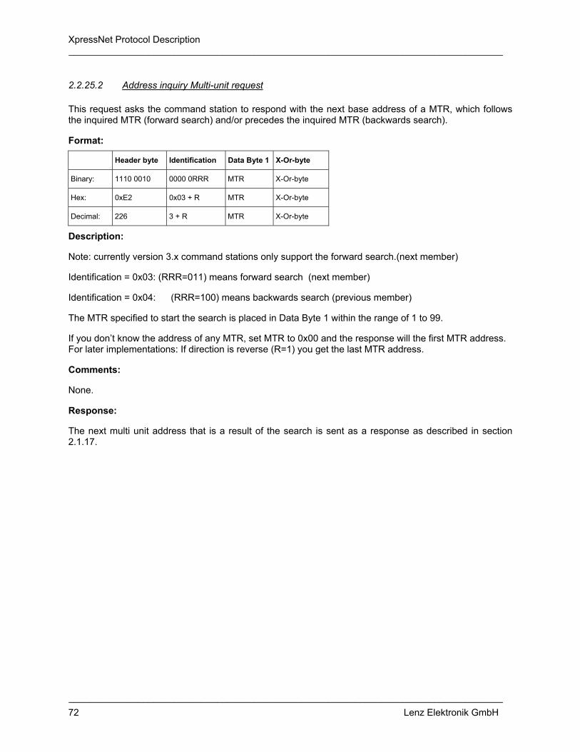
XpressNet Protocol Description __________________________________________________________________________________
__________________________________________________________________________________ 72 Lenz Elektronik GmbH
2.2.25.2 Address inquiry Multi-unit request
This request asks the command station to respond with the next base address of a MTR, which follows the inquired MTR (forward search) and/or precedes the inquired MTR (backwards search).
Format:
Header byte Identification Data Byte 1 X-Or-byte
Binary: 1110 0010 0000 0RRR MTR X-Or-byte
Hex: 0xE2 0x03 + R MTR X-Or-byte
Decimal: 226 3 + R MTR X-Or-byte
Description:
Note: currently version 3.x command stations only support the forward search.(next member)
Identification = 0x03: (RRR=011) means forward search (next member)
Identification = 0x04: (RRR=100) means backwards search (previous member)
The MTR specified to start the search is placed in Data Byte 1 within the range of 1 to 99.
If you don’t know the address of any MTR, set MTR to 0x00 and the response will the first MTR address. For later implementations: If direction is reverse (R=1) you get the last MTR address.
Comments:
None.
Response:
The next multi unit address that is a result of the search is sent as a response as described in section 2.1.17.

XpressNet Protocol Description __________________________________________________________________________________
__________________________________________________________________________________ 73 Lenz Elektronik GmbH
2.2.25.3 Address inquiry locomotive at command station stack request
This request returns the locomotive address, that is stored in the command station stack behind (forward search) and/or before (backwards search) the locomotive address specified in Data Byte 1 and Data Byte 2.
Format:
Header byte Identification Data Byte 1 Data Byte 2 X-Or-byte
Binary: 1110 0011 0000 01RR Address High Address Low X-Or-byte
Hex: 0xE3 0x05 + R AH AL X-Or-byte
Decimal: 227 5 + R AH AL X-Or-byte
Description:
Note: command stations version 3.x currently only supports the forward search (next member).
• Identification = 0x05: (RR=01) means forward search (next member) • Identification = 0x06: (RR=10) means backwards search (previous member)
Data Byte 1 and Data Byte 2 indicate the locomotive address (1 to 9999) within the command station database. This request will identify the next or previous address in the command station database. The locomotive address AH/AL is as specified in section 2.1.15
In this case you do not know the first locomotive in the database, you can set Adr High and Adr Low to 0x00 to get the first (or last) member in the database.
In the stack the order of locomotive addresses is not by number. They are sorted by the time the addresses was first used by an XpressNet device.
Comments:
None.
Response:
The next locomotive address that is a result of the search is sent as a response as described in section 2.1.17.

XpressNet Protocol Description __________________________________________________________________________________
__________________________________________________________________________________ 74 Lenz Elektronik GmbH
2.2.26 Delete locomotive from command station stack request
This request returns the locomotive address specified in Data Byte 1 and Data Byte 2 be removed from the command station stack.
Format:
Header byte Identification Data Byte 1 Data Byte 2 X-Or-byte
Binary: 1110 0011 0100 0100 Address High Address Low X-Or-byte
Hex: 0xE3 0x44 AH AL X-Or-byte
Decimal: 227 68 AH AL X-Or-byte
Description:
Data Byte 1 and Data Byte 2 indicate the locomotive address (1 to 9999) that is to be deleted from the command station stack. The locomotive address AH/AL is as specified in section 2.1.15
Comments:
The command station database contains information on each locomotive being controlled. Most command stations can only support a limited number of entries. When the database is full a member of the database must be removed before a new entry can be added. This problem is more frequently encountered with command stations with limited hardware that have limited space for locomotive address entries.
Before requesting that a specific entry be deleted, the XpressNet device should first determine that the entry is not being currently controlled by another XpressNet device. Otherwise the entry deleted would immediately be requested to be entered again.
Response:
None.

XpressNet Protocol Description __________________________________________________________________________________
__________________________________________________________________________________ 75 Lenz Elektronik GmbH
3 Command overview of information and responses sent to XpressNet devices (including a PC) from the command station
The following table summarizes the various responses sent to XpressNet devices. The precise meaning of the respective data bytes is described in the appropriate section within section 2.1 above. In the following tables, N in the header byte indicates the number of data bytes that follow.
V3 Instruction Call Byte Header Data Byte 1
Data Byte 2
Date Byte 3
Data Byte 4
Data Byte 5
Data Byte 6
Data Byte 7
x Normal inquiry P+0x40+GA
x Request Acknowledgement from Device
P+0x00+GA
x TBD (Future Command) P+0x20+GA
x Normal operation resumed 0x60 0x61 0x01 0x60
x Track power Off 0x60 0x61 0x00 0x61
x Emergency Stop 0x60 0x81 0x00 0x81
x Service Mode entry 0x60 0x61 0x02 0x63
x Feedback Broadcast 0xA0 0x40 + N ADR_1 DATA_1 ADR_2 DATA_2 etc. etc. X-Or
x Programming info. " short-circuit "
P+0x60+GA 0x61 0x12 X-Or
x Programming info. "Data byte not found"
P+0x60+GA 0x61 0x13 X-Or
x Programming info. "Command station busy"
P+0x60+GA 0x61 0x1F X-Or
x Programming info. "Command station ready "
P+0x60+GA 0x61 0x11 X-Or
x Service Mode response for Register and Paged Mode
P+0x60+GA 0x63 0x10 EE DATA X-Or
x Service Mode response for Direct CV mode
P+0x60+GA 0x63 0x14 CV DATA X-Or
Software-version(X-Bus V1 and V2)
P+0x60+GA 0x62 0x21 DATA X-Or
x Software-version (XpressNet only)
P+0x60+GA 0x63 0x21 DATA_1 DATA_2
X-Or
x Command station status indication response
P+0x60+GA 0x62 0x22 DATA X-Or
x Transfer Errors P+0x60+GA 0x61 0x80 X-Or
x Command station busy response
P+0x60+GA 0x61 0x81 X-Or
x Instruction not supported by command station
P+0x60+GA 0x61 0x82 X-Or

XpressNet Protocol Description __________________________________________________________________________________
__________________________________________________________________________________ 76 Lenz Elektronik GmbH
V3 Instruction Call Byte Header Data Byte 1
Data Byte 2
Date Byte 3
Data Byte 4
Data Byte 5
Data Byte 6
Data Byte 7
x Accessory Decoder information response
P+0x60+GA 0x42 Addr DATA X-Or
Locomotive is available for operation
P+0x60+GA 0x83 Loco addr
Loco data 1
Loco data 2
X-Or
Locomotive is being operated by another device
P+0x60+GA 0xA3 Loco addr
Loco data 1
Loco data 2
X-Or
Locomotive is available for operation
P+0x60+GA 0x84 Loco addr
Loco data 1
Loco data 2
ModSel X-Or
Locomotive is being operated by another device
P+0x60+GA 0xA4 Loco addr
Loco data 1
Loco data 2
ModSel X-Or
x Locomotive information normal locomotive
P+0x60+GA 0xE4 Identification
Speed FKTA FKTB X-Or
x Locomotive information for a locomotive in a multi-unit
P+0x60+GA 0xE5 Identification
Speed FKTA FKTB MTR X-Or
x Locomotive information for the Multi-unit address
P+0x60+GA 0xE2 Identification
Speed X-Or
x Locomotive information for a locomotive in a Double Header
P+0x60+GA 0xE6 Identification
Speed FKTA FKTB Addr High
Addr Low
X-Or
x Locomotive is being operated by another device response (XpressNet only)
P+0x60+GA 0xE3 0x40 Addr High
Addr Low
X-Or
x Function status response (XpressNet only)
P+0x60+GA 0xE3 0x50 STAT 0 STAT 1 X-Or
x Locomotive information response for address retrieval requests (XpressNet only)
P+0x60+GA 0xE3 0x30 + K Addr High
Addr Low
X-Or
Double Header available P+0x60+GA 0xC5 0x04 Loco addr 1
Loco data 1
Loco data 2
Loco addr 2
X-Or
Double Header occupied P+0x60+GA 0xC5 0x05 Loco addr 1
Loco data 1
Loco data 2
Loco addr 2
X-Or
Double Header available P+0x60+GA 0xC6 0x04 Loco addr 1
Loco data 1
Loco data 2
Loco addr 2
ModSel
X-Or
Double Header occupied P+0x60+GA 0xC6 0x05 Loco addr 1
Loco data 1
Loco data 2
Loco addr 2
ModSel
X-Or
x Double Header error response (X-Bus V1 and V2)
P+0x60+GA 0x61 0x80 + F X-Or
x XpressNet MU+DH error message response
P+0x60+GA 0xE1 0x80 + F X-Or

XpressNet Protocol Description __________________________________________________________________________________
__________________________________________________________________________________ 77 Lenz Elektronik GmbH
4 Command overview of requests transmitted sent from XpressNet devices (including a PC) to the command station
The following table summarizes the various requests sent by the PC to the command station through the LI100. The precise meaning of the respective data bytes is described in the appropriate section within section 2.2 above. In the following tables, N in the header byte indicated the number of data bytes that follow.
V3 Instruction Header Identi-fication
Data Byte 1
Data Byte 2
Data Byte 3
Data Byte 4
Data Byte 6
Data Byte 6
Acknowledgement Response 0x20 0x20
x Resume operations request 0x21 0x81 0xA0
x Stop operations request (emergency off)
0x21 0x80 0xA1
x Stop all locomotives request (emergency stop)
0x80 0x80
Emergency stop a locomotive (X-Bus V1 and V2)
0x91 Loco addr
X-Or
x Emergency stop a locomotive (XpressNet)
0x92 Addr High Addr Low X-Or
Emergency stop selected locomotives (X-Bus V1 and V2)
0x90 + N Loco addr 1
Loco addr 2
etc. Loco addr N
X-Or
x Register Mode read request (Register Mode)
0x22 0x11 REG X-Or
x Direct Mode CV read request (CV mode)
0x22 0x15 CV X-Or
x Paged Mode read request (Paged Mode)
0x22 0x14 CV X-Or
x Request for Service Mode results 0x21 0x10 0x31
x Register Mode write request (Register Mode)
0x23 0x12 REG DATA X-Or
x Direct Mode CV write request (CV mode)
0x23 0x16 CV DATA X-Or
x Paged Mode write request (Paged mode)
0x23 0x17 CV DATA X-Or

XpressNet Protocol Description __________________________________________________________________________________
__________________________________________________________________________________ 78 Lenz Elektronik GmbH
V3 Instruction Header Identi-fication
Data Byte 1
Data Byte 2
Data Byte 3
Data Byte 4
Data Byte 6
Data Byte 6
x Command station software-version request
0x21 0x21 0x00
x Command station status request 0x21 0x24 0x05
Set command station power-up mode
0x22 0x22 00000M00 X-Or
x Accessory Decoder information request
0x42 Addr Nibble X-Or
x Accessory Decoder operation request
0x52 Addr DAT X-Or
Locomotive information requests (X-Bus V1)
0xA1 Loco addr
X-Or
Locomotive information requests (X-Bus V1 and V2)
0xA2 Loco addr
ModSel X-Or
x Locomotive information requests (XpressNet only)
0xE3 0x00 Addr High Addr Low
X-Or
x Function status request (XpressNet only)
0xE3 0x07 Addr High Addr Low
X-Or
Locomotive operations (X-Bus V1) 0xB3 Loco addr
Loco data 1
Loco data 2
X-Or
Locomotive operations (X-Bus V2) 0xB4 Loco addr
Loco data 1
Loco data 2
ModSel X-Or
x Locomotive speed and direction operations (XpressNet only)
0xE4 0x10 0x11 0x12 0x13
Addr High Addr Low
Speed X-Or
x Function operation instructions (XpressNet only)
0xE4 0x20 0x21 0x22
Addr High Addr Low
Group X-Or
x Set function state (XpressNet only)
0xE4 0x24 0x25 0x26
Addr High Addr Low
Group X-Or
Establish Double Header 0xC3 0x05 Loco addr 1
Loco addr 2
X-Or
Dissolve Double Header 0xC3 0x04 Loco addr 1
Loco addr 2
X-Or
x Establish Double Header 0xE5 0x43 ADR1 H ADR1 L ADR2 H ADR2 L X-Or
x Dissolve Double Header 0xE5 0x43 ADR1 H ADR1 L 0x00 0x00 X-Or

XpressNet Protocol Description __________________________________________________________________________________
__________________________________________________________________________________ 79 Lenz Elektronik GmbH
V3 Instruction Header Identi-fication
Data Byte 1
Data Byte 2
Data Byte 3
Data Byte 4
Data Byte 6
Data Byte 6
x Operations Mode Programming byte mode write request
0xE6 0x30 Addr High Addr Low 0xEC + C CV DATA X-Or
x Operations Mode programming bit mode write request
0xE6 0x30 Addr High Addr Low 0xE8 + C CV DATA X-Or
x Add a locomotive to a multi-unit request
0xE4 0x40 + R Addr High Addr Low MTR X-Or
x Remove a locomotive from a Multi-unit request
0xE4 0x42 Addr High Addr Low MTR X-Or
x Address inquiry member of a Multi-unit request
0xE4 0x01 + R MTR Addr High
Addr Low X-Or
x Address inquiry Multi-unit request 0xE2 0x03 + R MTR X-Or
x Address inquiry locomotive at command station stack request
0xE3 0x05 + R Addr High Addr Low X-Or
x Delete locomotive from command station stack request
0xE3 0x44 Addr High Addr Low X-Or

XpressNet Protocol Description __________________________________________________________________________________
__________________________________________________________________________________ 80 Lenz Elektronik GmbH
5 Document Version History
In the following modified or extended formulations and descriptions are called: “supplement” - additional information is provided; "new" – new information or command; and “correction” – incorrect information provided before has been corrected.
12/2001 first edition
12/2002 second edition:
• XpressNet Architecture - supplement
• XpressNet timing constraints – new
• Programming considerations for XpressNet devices - new
• Programming notes - supplement
• LI100 Computer Interface - supplement
• Future Expansion - new
• Addition of call bytes in section 2.1 – new
• Normal inquiry (2.1.1) - new
• Request Acknowledgement from Device (2.1.2) – new
• Transfer Errors (2.1.8) - new
• Acknowledgement Response (2.2.1) - new
• Emergency stop a locomotive (XpressNet) (2.2.5.2) - correction
• Direct Mode CV write request (CV mode) (2.2.12) - correction
• Operations Mode programming bit mode write request (2.2.23.2) – correction
6/2003 third edition:
• LI101 requests/responses for configuration added