Embed Size (px)
Citation preview
Silver+ Locomotive decoder 1
The DIGITAL plus SILVER+ locomotive decoder is suitable for all DC locomotives with continuous current draw of 1.0 Amp. or less. The characteristics of the decoder are: ∗ Super smooth and silent high frequency back-emf motor control ∗ Full RailCom NMRA DCC Bi-directional support ∗ Five function outputs rated at 500mA each ∗ Each function output supports F0-F28 with simplified function mapping ∗ Directional or independent lighting with dimming and special effects ∗ Support for automatic uncoupling control ∗ Asymmetric DCC support including directional stopping ∗ Adjustable precision stopping control ∗ Low speed gear for switching operations ∗ Selectable for operation with 14/27, or 28/128 speed steps ∗ Operation on conventional DC layouts is possible or can be disabled ∗ Motor output = 1A continuous, 1.6A max, > 5 A stall ∗ Motor and function outputs protected ∗ Support for Advanced Consist Control and Extended Addressing ∗ Support for all forms of programming as described in RP-9.2.1 & RP-9.2.3 ∗ Supports service mode decoder lock ∗ Size: L 0.90" x W 0.65"x H 0.12" L 23mm x W 16.5mm x H 3.0mm
Silver+ Silent-Back EMF DCC Decoder
Art. No. 10331-01 December 2009
Silver+ Locomotive decoder 2
2
SILVER+ Decoder feature set The following contains a short introduction of the features of the SILVER+ decoder as well as information on how to use them. For more detailed information please refer to the "SILVER+ decoder" information which can be downloaded from the Lenz Elektronik GmbH website: www.lenz.com.
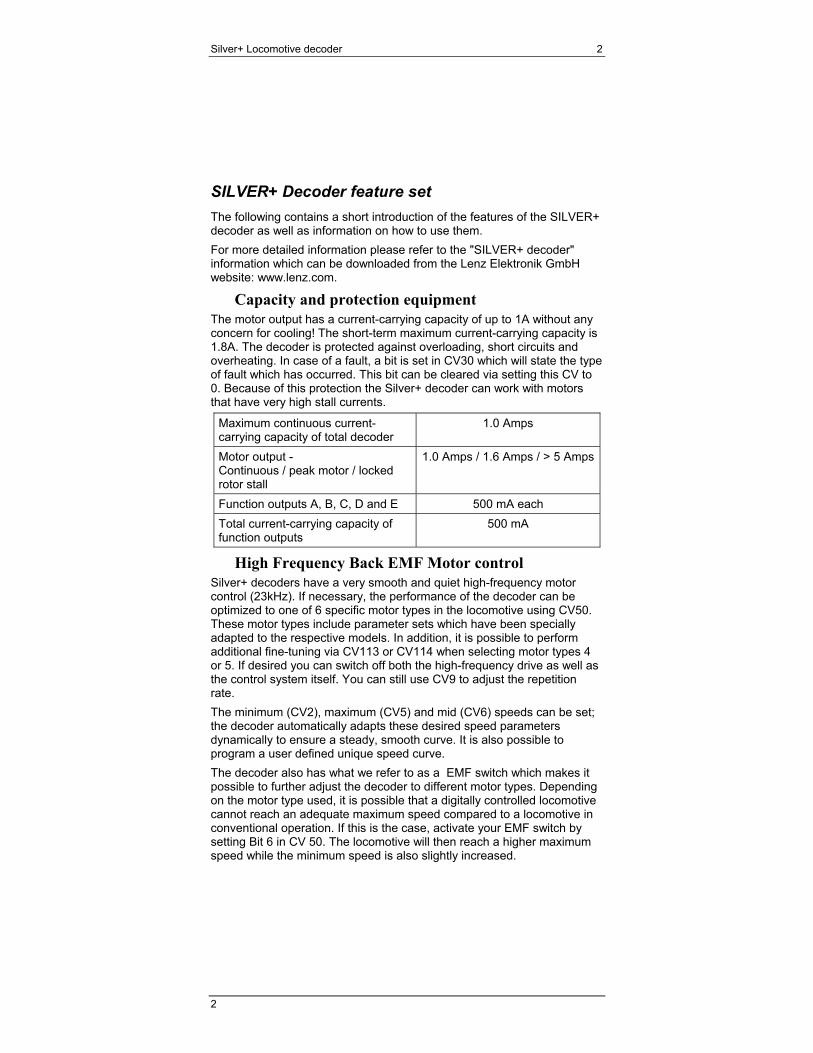
Capacity and protection equipment The motor output has a current-carrying capacity of up to 1A without any concern for cooling! The short-term maximum current-carrying capacity is 1.8A. The decoder is protected against overloading, short circuits and overheating. In case of a fault, a bit is set in CV30 which will state the type of fault which has occurred. This bit can be cleared via setting this CV to 0. Because of this protection the Silver+ decoder can work with motors that have very high stall currents.
Maximum continuous current-carrying capacity of total decoder
1.0 Amps
Motor output - Continuous / peak motor / locked rotor stall
1.0 Amps / 1.6 Amps / > 5 Amps
Function outputs A, B, C, D and E 500 mA each Total current-carrying capacity of function outputs
500 mA
High Frequency Back EMF Motor control Silver+ decoders have a very smooth and quiet high-frequency motor control (23kHz). If necessary, the performance of the decoder can be optimized to one of 6 specific motor types in the locomotive using CV50. These motor types include parameter sets which have been specially adapted to the respective models. In addition, it is possible to perform additional fine-tuning via CV113 or CV114 when selecting motor types 4 or 5. If desired you can switch off both the high-frequency drive as well as the control system itself. You can still use CV9 to adjust the repetition rate. The minimum (CV2), maximum (CV5) and mid (CV6) speeds can be set; the decoder automatically adapts these desired speed parameters dynamically to ensure a steady, smooth curve. It is also possible to program a user defined unique speed curve. The decoder also has what we refer to as a EMF switch which makes it possible to further adjust the decoder to different motor types. Depending on the motor type used, it is possible that a digitally controlled locomotive cannot reach an adequate maximum speed compared to a locomotive in conventional operation. If this is the case, activate your EMF switch by setting Bit 6 in CV 50. The locomotive will then reach a higher maximum speed while the minimum speed is also slightly increased.
Silver+ Locomotive decoder 3
Special Features RailCom
The Silver+ is equipped with RailCom technology. In addition to the locomotive address, other data (e.g. speed, CV content) can be transmitted from the locomotive via the track back to the system. The information sent is received by a RailCom detector and then displayed. Which data the decoder is to send is set in CV28. Set Bit 4 in CV29 to enable the transmission function.
Switching speed function The switching speed halves the speed table. This facilitates particularly sensitive control during the switching process. Use function 3 (function setting, can be altered in CV58) to enable and disable the switching speed. If the shunting speed is enabled, the constant braking distance is disabled. The switching speed is enabled as long as the function is active.
Automatic Braking Control (ABC) for simple signal stop and slow approach
You can carry out a particularly simple stop at a signal using the ABC braking module. Depending on the signal position, this module creates an asymmetric track voltage in the braking section in front of the signal. The decoder reacts to this. Combined with the constant braking distance, precise on-the-spot stopping in front of red signals is not a problem. Of course, passage in the opposite direction is also possible. The signal indication "slow approach/caution" can be set using CV53. You can operate all functions during the signal stop or slow approach – you can even reverse away again from the red signal! These special ABC modules can be used to assemble a very simple block section. Activate the ABC control by setting Bit 2 (1) in CV51.
Push-pull train control A push-pull train control can be set if the ABC braking module is used. There are two different options: push-pull operation with and without intermediate stops. The latter also takes slow-approach sections into account. The push-pull train control is activated in CV51, Bit 4 (3) and Bit 5 (4). The stopping time at the end of the track is set in CV54 (1 to 255 sec).
Constant braking distance with Automatic Braking Control If the decoder recognises the command “Stop“ while in ABC mode, the locomotive will stop after the set braking distance has been covered. This braking distance is independent of the speed of the locomotive. You can activate the constant braking distance with ABC by setting bit 1(0) in CV51.
Constant braking distance with speed step 0 During the transition from an active speed step to speed step 0 (e.g. moving the speed control knob to the left limit-stop), the locomotive/train
Silver+ Locomotive decoder 4
4
will travel a settable, pre-defined braking distance. This braking distance does not depend on the speed of the locomotive/train. Enable the constant braking distance function (this requires setting Bit 0(1) in CV51. If this bit is not set, the decoder will use the normal speed-dependent braking delay). The braking distance is defined by the value set in CV52. Since the motors and gear ratios of locomotives vary, the braking distance differs from locomotive to locomotive even if the same value is set in CV52. Use a short test section to measure how long your locomotive’s braking distance will be with a given value set in CV52. Start with the default value (100) in CV52. Accelerate your locomotive until it has reached average speed. At a chosen point in time, set the speed to 0. This requires moving the speed control to the stop position, if you are using the LH100, keep pressing the < key until the speed is set to 0 or until the locomotive address is displayed (if using the LH100, do not press key ! This result in a locomotive-specific emergency stop and the delays in the locomotive decoder will not be enabled!). Measure the covered braking distance. Increase or decrease the value in CV52, e.g. in steps of 10, and carry out another measurement. You will thus create a table which will indicate the braking distances in relation to the values set in CV52. Important advice: The constant braking distance is only effective if the speed is changed to 0. If the speed is decreased from e.g. 28 to 10, the speed-dependent delay from CV4 becomes effective. The constant braking distance is disabled while the switching speed function is switched on (default setting F3), or if the function to disable acceleration/deceleration is activated (default setting F4). Either of these two features can also be used if you wish to interrupt a constant braking process prematurely. The constant braking distance does not function in analogue DC mode.
Function for disabling of acceleration and deceleration delay Use function F4 (function assignment can be altered in CV59) to disable the acceleration and braking delay as well as the constant braking distance during operation. The delays are disabled as long as the function is active.
Mapping function outputs Using function mapping you can define which functions of the digital system are used to control the A, B, C, D, and E function outputs. CVs 33-47 are used for Functions 0-12 while 129-144 are used for Functions 13-28
Silver+ Locomotive decoder 5
Lighting effect at function outputs Special lighting effects can be assigned to each of the function outputs. The lighting effects for the function outputs A and B are set in CV60 and for the function outputs C and D in CV62. If you wish to switch the effects with a function of the digital system, you can make the allocations to functions F1 to F8 in CV61 (for function outputs A and B) and CV64 (for function outputs C and D). The effects available are shown in the CV table defined later in this manual.
Coupling control The decoder allows for a controlling of remote couplings at all function outputs. The selected output provides full power for a settable period of time (kick duration) and reduced power after this period has expired. The amount the power is decreased can be set using the value for brightness for the chosen output. You can also set if and how long the locomotive will move during the coupling process. (CVs 145-148)
Preparing to Install the SILVER+ decoder
A locomotive that runs well under DC will run exceptionally well under DCC. Replace worn out motor brushes and burned out light bulbs. Clean any dirt or oxidation from the wheels and pickups, and make sure that electrical contact is good. Now is also a good time to lubricate your locomotive.
Some advice on installing the decoder: Although the SILVER+ decoder has many internal safeguards to prevent damage, you must not allow any metal part of the locomotive to touch the surface components of the decoder. This could cause a direct internal short circuit and the decoder will be destroyed. The motor brushes MUST also be completely isolated from the rail pickup. Achieving isolation may require some different approaches on different locomotives, perhaps unsoldering wires or placing a thin piece of insulating plastic between the motor and the locomotive frame. If you have a VOM, check for infinite resistance between the motor and all the wheels. Take special note that a short might occur when the loco body is reinstalled. DO NOT WRAP decoder with electrical tape or shrink wrap! Doing so will impede air circulation and degrade the performance of the decoder. Instead, put electrician tape over any part of the locomotive frame or body that might touch the decoder and use double sided foam mounting tape to mount the decoder. This will prevent short circuits without 'suffocating' the decoder.
Silver+ Locomotive decoder 6
6
The SILVER+ decoder cannot be set up for simultaneous use for 2-rail pickup and overhead cantenary or trolley operation. If the locomotive is turned the wrong way, the decoder could get twice the track voltage, which would destroy it!
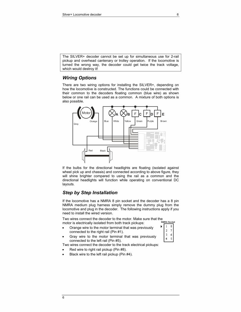
Wiring Options There are two wiring options for installing the SILVER+, depending on how the locomotive is constructed. The functions could be connected with their common to the decoders floating common (blue wire) as shown below or one rail can be used as a common. A mixture of both options is also possible.
Motor A C D EB F
Orange Green Purple BrownGrey
Red Black
White YellowBlue
F F
If the bulbs for the directional headlights are floating (isolated against wheel pick up and chassis) and connected according to above figure, they will shine brighter compared to using the rail as a common and the directional headlights will function while operating on conventional DC layouts.
Step by Step Installation If the locomotive has a NMRA 8 pin socket and the decoder has a 8 pin NMRA medium plug harness simply remove the dummy plug from the locomotive and plug in the decoder. The following instructions apply if you need to install the wired version. Two wires connect the decoder to the motor. Make sure that the motor is electrically isolated from both track pickups: • Orange wire to the motor terminal that was previously
connected to the right rail (Pin #1). • Gray wire to the motor terminal that was previously
connected to the left rail (Pin #5). Two wires connect the decoder to the track electrical pickups: • Red wire to right rail pickup (Pin #8). • Black wire to the left rail pickup (Pin #4).
Silver+ Locomotive decoder 7
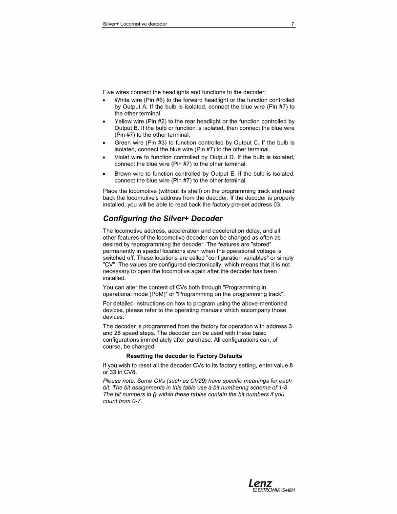
Five wires connect the headlights and functions to the decoder: • White wire (Pin #6) to the forward headlight or the function controlled
by Output A. If the bulb is isolated, connect the blue wire (Pin #7) to the other terminal.
• Yellow wire (Pin #2) to the rear headlight or the function controlled by Output B. If the bulb or function is isolated, then connect the blue wire (Pin #7) to the other terminal.
• Green wire (Pin #3) to function controlled by Output C. If the bulb is isolated, connect the blue wire (Pin #7) to the other terminal.
• Violet wire to function controlled by Output D. If the bulb is isolated, connect the blue wire (Pin #7) to the other terminal.
• Brown wire to function controlled by Output E. If the bulb is isolated, connect the blue wire (Pin #7) to the other terminal.
Place the locomotive (without its shell) on the programming track and read back the locomotive's address from the decoder. If the decoder is properly installed, you will be able to read back the factory pre-set address 03.
Configuring the Silver+ Decoder The locomotive address, acceleration and deceleration delay, and all other features of the locomotive decoder can be changed as often as desired by reprogramming the decoder. The features are "stored" permanently in special locations even when the operational voltage is switched off. These locations are called "configuration variables" or simply "CV". The values are configured electronically, which means that it is not necessary to open the locomotive again after the decoder has been installed. You can alter the content of CVs both through "Programming in operational mode (PoM)" or "Programming on the programming track". For detailed instructions on how to program using the above-mentioned devices, please refer to the operating manuals which accompany those devices. The decoder is programmed from the factory for operation with address 3 and 28 speed steps. The decoder can be used with these basic configurations immediately after purchase. All configurations can, of course, be changed.
Resetting the decoder to Factory Defaults If you wish to reset all the decoder CVs to its factory setting, enter value 8 or 33 in CV8. Please note: Some CVs (such as CV29) have specific meanings for each bit. The bit assignments in this table use a bit numbering scheme of 1-8 The bit numbers in () within these tables contain the bit numbers if you count from 0-7.
Silver+ Locomotive decoder 8
8
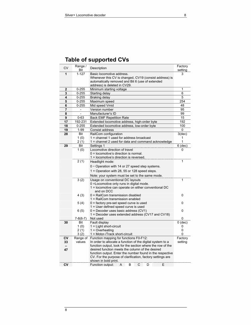
Table of supported CVs CV Range /
Bit Description Factory setting
1 1-127 Basic locomotive address. Whenever this CV is changed, CV19 (consist address) is automatically removed and Bit 6 (use of extended address) is deleted in CV29.
3
2 0-255 Minimum starting voltage 1 3 0-255 Starting delay 6 4 0-255 Braking delay 5 5 0-255 Maximum speed 254 6 0-255 Mid speed Vmid 48 7 - Version number 95 8 - Manufacturer’s ID 99 9 0-63 Back EMF Repetition Rate 15
17 192-231 Extended locomotive address, high-order byte 192 18 0-255 Extended locomotive address, low-order byte 100 19 1-99 Consist address 0 28 Bit RailCom configuration 3(dec)
1 (0) 1 = channel 1 used for address broadcast 1 2 (1) 1 = channel 2 used for data and command acknowledge 1
29 Bit Settings 1 6 (dec) 1 (0) Locomotive direction of travel
0 = locomotive’s direction is normal. 1 = locomotive’s direction is reversed.
0
2 (1) Headlight mode: 1 0 = Operation with 14 or 27 speed step systems.
1 = Operation with 28, 55 or 128 speed steps. Note: your system must be set to the same mode.
3 (2) Usage on conventional DC layouts 0 =Locomotive only runs in digital mode. 1 = locomotive can operate on either conventional DC
and on DCC
1
4 (3) 0 = RailCom transmission disabled 1 = RailCom transmission enabled
0
5 (4) 0 = factory pre-set speed curve is used 1 = User defined speed curve is used
0
6 (5) 0 = Decoder uses basic address (CV1) 1 = Decoder uses extended address (CV17 and CV18)
0
7-8(6-7) Not used 0 30 Bit Fault display 0 (dec)
1 (0) 1 = Light short-circuit 0 2 (1) 1 = Overheating 0 3 (2) 1 = Motor-/Track short-circuit 0
CV 33 –
47
Range of values
Function mapping for functions F0-F12: In order to allocate a function of the digital system to a function output, look for the section where the row of the desired function meets the column of the desired function output. Enter the number found in the respective CV. For the purpose of clarification, factory settings are shown in bold print.
Factory setting
CV Function output: A B C D E
Silver+ Locomotive decoder 9
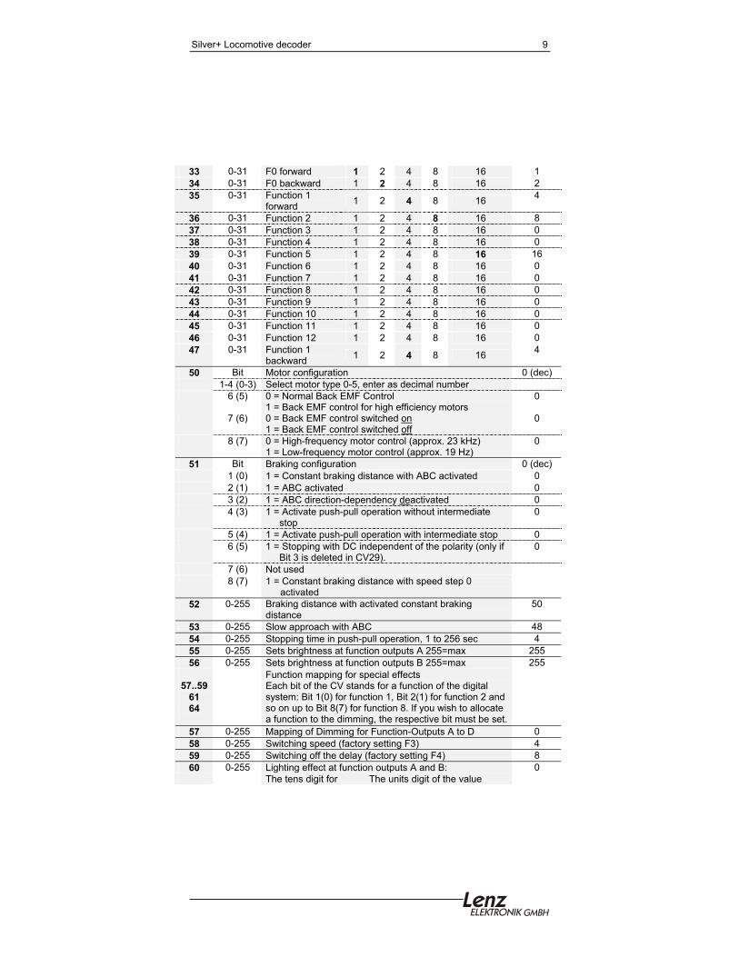
33 0-31 F0 forward 1 2 4 8 16 1 34 0-31 F0 backward 1 2 4 8 16 2 35 0-31 Function 1
forward 1 2 4 8 16 4
36 0-31 Function 2 1 2 4 8 16 8 37 0-31 Function 3 1 2 4 8 16 0 38 0-31 Function 4 1 2 4 8 16 0 39 0-31 Function 5 1 2 4 8 16 16 40 0-31 Function 6 1 2 4 8 16 0 41 0-31 Function 7 1 2 4 8 16 0 42 0-31 Function 8 1 2 4 8 16 0 43 0-31 Function 9 1 2 4 8 16 0 44 0-31 Function 10 1 2 4 8 16 0 45 0-31 Function 11 1 2 4 8 16 0 46 0-31 Function 12 1 2 4 8 16 0 47 0-31 Function 1
backward 1 2 4 8 16 4
50 Bit Motor configuration 0 (dec) 1-4 (0-3) Select motor type 0-5, enter as decimal number 6 (5) 0 = Normal Back EMF Control
1 = Back EMF control for high efficiency motors 0
7 (6) 0 = Back EMF control switched on 1 = Back EMF control switched off
0
8 (7) 0 = High-frequency motor control (approx. 23 kHz) 1 = Low-frequency motor control (approx. 19 Hz)
0
51 Bit Braking configuration 0 (dec) 1 (0) 1 = Constant braking distance with ABC activated 0 2 (1) 1 = ABC activated 0 3 (2) 1 = ABC direction-dependency deactivated 0 4 (3) 1 = Activate push-pull operation without intermediate
stop 0
5 (4) 1 = Activate push-pull operation with intermediate stop 0 6 (5) 1 = Stopping with DC independent of the polarity (only if
Bit 3 is deleted in CV29). 0
7 (6) Not used 8 (7) 1 = Constant braking distance with speed step 0
activated
52 0-255 Braking distance with activated constant braking distance
50
53 0-255 Slow approach with ABC 48 54 0-255 Stopping time in push-pull operation, 1 to 256 sec 4 55 0-255 Sets brightness at function outputs A 255=max 255 56 0-255 Sets brightness at function outputs B 255=max 255
57..59
61 64
Function mapping for special effects Each bit of the CV stands for a function of the digital system: Bit 1(0) for function 1, Bit 2(1) for function 2 and so on up to Bit 8(7) for function 8. If you wish to allocate a function to the dimming, the respective bit must be set.
57 0-255 Mapping of Dimming for Function-Outputs A to D 0 58 0-255 Switching speed (factory setting F3) 4 59 0-255 Switching off the delay (factory setting F4) 8 60 0-255 Lighting effect at function outputs A and B: 0
The tens digit for The units digit of the value
Silver+ Locomotive decoder 10
10
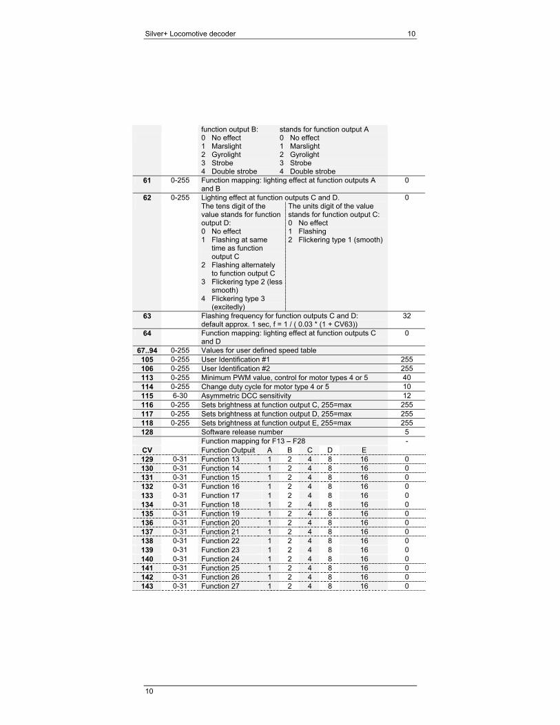
function output B: stands for function output A 0 No effect
1 Marslight 2 Gyrolight 3 Strobe 4 Double strobe
0 No effect 1 Marslight 2 Gyrolight 3 Strobe 4 Double strobe
61 0-255 Function mapping: lighting effect at function outputs A and B
0
62 0-255 Lighting effect at function outputs C and D. 0 The tens digit of the
value stands for function output D: 0 No effect 1 Flashing at same
time as function output C
2 Flashing alternately to function output C
3 Flickering type 2 (less smooth)
4 Flickering type 3 (excitedly)
The units digit of the value stands for function output C: 0 No effect 1 Flashing 2 Flickering type 1 (smooth)
63 Flashing frequency for function outputs C and D: default approx. 1 sec, f = 1 / ( 0.03 * (1 + CV63))
32
64 Function mapping: lighting effect at function outputs C and D
0
67..94 0-255 Values for user defined speed table 105 0-255 User Identification #1 255 106 0-255 User Identification #2 255 113 0-255 Minimum PWM value, control for motor types 4 or 5 40 114 0-255 Change duty cycle for motor type 4 or 5 10 115 6-30 Asymmetric DCC sensitivity 12 116 0-255 Sets brightness at function output C, 255=max 255 117 0-255 Sets brightness at function output D, 255=max 255 118 0-255 Sets brightness at function output E, 255=max 255 128 Software release number 5
Function mapping for F13 – F28 - CV Function Outpuit A B C D E 129 0-31 Function 13 1 2 4 8 16 0 130 0-31 Function 14 1 2 4 8 16 0 131 0-31 Function 15 1 2 4 8 16 0 132 0-31 Function 16 1 2 4 8 16 0 133 0-31 Function 17 1 2 4 8 16 0 134 0-31 Function 18 1 2 4 8 16 0 135 0-31 Function 19 1 2 4 8 16 0 136 0-31 Function 20 1 2 4 8 16 0 137 0-31 Function 21 1 2 4 8 16 0 138 0-31 Function 22 1 2 4 8 16 0 139 0-31 Function 23 1 2 4 8 16 0 140 0-31 Function 24 1 2 4 8 16 0 141 0-31 Function 25 1 2 4 8 16 0 142 0-31 Function 26 1 2 4 8 16 0 143 0-31 Function 27 1 2 4 8 16 0
Silver+ Locomotive decoder 11
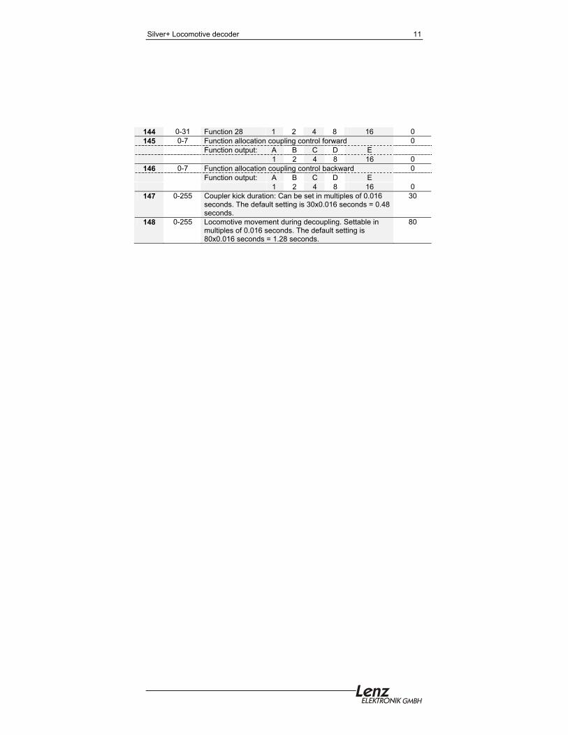
144 0-31 Function 28 1 2 4 8 16 0 145 0-7 Function allocation coupling control forward 0
Function output: A B C D E 1 2 4 8 16 0
146 0-7 Function allocation coupling control backward 0 Function output: A B C D E 1 2 4 8 16 0
147 0-255 Coupler kick duration: Can be set in multiples of 0.016 seconds. The default setting is 30x0.016 seconds = 0.48 seconds.
30
148 0-255 Locomotive movement during decoupling. Settable in multiples of 0.016 seconds. The default setting is 80x0.016 seconds = 1.28 seconds.
80
Silver+ Locomotive decoder 12
12
North American Warranty Lenz GmbH does everything it can do to ensure that its products are free from defects and will operate for the life of your model railroad equipment. From time to time even the best engineered products fail either due to a faulty part or from accidental mistakes in installation. To protect your investment in Digital plus products, Lenz GmbH offers a very aggressive 10 year Limited Warranty.
This warranty is not valid if the user has altered, intentionally misused the Digital Plus product, or removed the product's protection, for example the heat shrink from decoders and other devices. In this case a service charge will be applied for all repairs or replacements. Should the user desire to alter a Digital Plus Product, they should contact Lenz GmbH for prior authorization.
Year One: A full repair or replacement will be provided to the original purchaser for any item that that has failed due to manufacturer defects or failures caused by accidental user installation problems. Should the item no longer be produced and the item is not repairable, a similar item will be substituted at the manufacturer’s discretion. The user must pay for shipping to an authorized Lenz GmbH warranty center.
Year 2 and 3: A full replacement for any item will be provided that has failed due to manufacturer defects. If the failure was caused by accidental user installation or use, a minimal service charge may be imposed. Should the item no longer be produced and the item is not repairable, a similar item will be substituted at the manufacturer’s discretion. The user must pay shipping to and from the authorized Lenz GmbH warranty center during this portion of the warranty period.
Year 4-10: A minimal service charge will be placed on each item that has failed due to manufacturer defects and/or accidental user installation problems. Should the item no longer be produced and the item is not repairable, a similar item will be substituted at the manufacturer’s discretion. The user must pay shipping to and from the authorized Lenz GmbH warranty center during this portion of the warranty period.
Please contact your dealer or authorized Lenz GmbH warranty center for specific instructions and current service charges prior to returning any equipment for repair.
Hüttenbergstraße 29
35398 Gießen, Germany Hotline: 06403 900 133
Fax: 06403 900155 [email protected] http://www.lenz.com
Lenz Agency of North America PO Box 143
Chelmsford, MA 01824 ph: 978 250 1494
fax: 978 455 LENZ [email protected]
This equipment complies with Part 15 of FCC Rules. Operation is subject to the following two conditions: (1) this device may not cause harmful interference, and (2) this device must accept any interference received, including interference that may cause undesired operation.
Please save this manual for future reference!
© 2009 Lenz GmbH, All Rights Reserved. Commercial use not authorized without a license.