Embed Size (px)
Citation preview
X-Lam Designer for Derix Cross Laminated Timber
User manual
Page 1
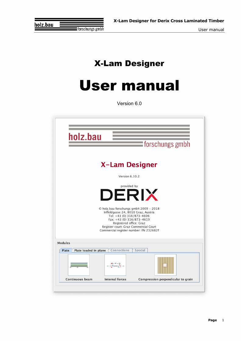
X-Lam Designer
User manual Version 6.0
X-Lam Designer for Derix Cross Laminated Timber
User manual
Page 2
TABLE OF CONTENTS
1 General .................................................................... 4 1.1 System requirements.............................................................. 4 1.2 Design methods ..................................................................... 4 1.3 Standards and guidelines used ................................................. 4
1.3.1 Base documents ............................................................................................. 4 1.3.2 National Annexes ........................................................................................... 4
1.4 Translations ........................................................................... 5
2 General program build-up ......................................... 6 2.1 Modules ................................................................................ 6 2.2 Menu bar .............................................................................. 8 2.3 Buttons ................................................................................. 9 2.4 Settings/Preferences............................................................... 9 2.5 Information ......................................................................... 13 2.6 Project information ............................................................... 13
3 Module „CLT-Plate 1D – Continuous beam“ ............. 15 3.1 Input information ................................................................. 15
3.1.1 General ....................................................................................................... 15 3.1.2 Structural system ......................................................................................... 16 3.1.3 Cross section ............................................................................................... 16 3.1.4 Loads ......................................................................................................... 17 3.1.5 Fire ............................................................................................................ 19 3.1.6 Vibrations.................................................................................................... 19
3.2 Results and output ............................................................... 20 3.2.1 Cross section values ..................................................................................... 20 3.2.2 Summary of the results................................................................................. 20 3.2.3 Detailed results ............................................................................................ 22
4 Module „CLT-Plate 1D – Internal forces“ ................. 25 4.1 Input data ........................................................................... 25
4.1.1 Cross section ............................................................................................... 25 4.1.2 Fire ............................................................................................................ 25 4.1.3 Type of calculation, internal forces, design factors and specifications concerning
stability .................................................................................................. 25 4.2 Results and output ............................................................... 26
4.2.1 Cross section values ..................................................................................... 26 4.2.2 Summary of the results................................................................................. 26 4.2.3 Detailed results ............................................................................................ 27
5 Module „CLT-Plate loaded in plane“......................... 28 5.1 Input information ................................................................. 28
X-Lam Designer for Derix Cross Laminated Timber
User manual
Page 3
5.1.1 Cross section ............................................................................................... 28 5.1.2 Fire ............................................................................................................ 28 5.1.3 Internal forces and design factors .................................................................. 28
5.2 Results and output ............................................................... 29 5.2.1 Cross section values ..................................................................................... 29 5.2.2 Summary of the results................................................................................. 29
6 Module „ Compression perpendicular to grain“ ........ 30 6.1 Input information ................................................................. 30
6.1.1 Cross-section ............................................................................................... 30 6.1.2 Plate dimensions and gap execution ............................................................... 31 6.1.3 Load data and design factors ......................................................................... 31 6.1.4 Load configuration ........................................................................................ 31 6.1.5 Calculation options ....................................................................................... 32
6.2 Results and Output ............................................................... 32
7 Contact................................................................... 33
X-Lam Designer for Derix Cross Laminated Timber
User manual
Page 4
1 GENERAL
1.1 System requirements
- Java SE Runtime Environment (JRE 8) A free version of JRE can be downloaded from http://www.java.com/download/
1.2 Design methods
Detailed information about the design methods implemented for CLT can be found in the CLThandbook | Solid timber structures made of cross laminated timber (CLT) | Verifications on the basis of the new European concept for construction standards (only available in German) and the BSP Wiki.
The CLThandbook (ISBN 978-3-85125-109-8; only available in German) can be ordered at [email protected].
1.3 Standards and guidelines used
1.3.1 Base documents
- DIN EN 1990:2010-12 and ON EN 1990:2003-03 respectively: Basis of structural design
- DIN EN 1991-1-1:2010-12 and ON EN 1991-1-1:2003-03 respectively: Actions on structures Part 1-1: General actions – Densities, self-weight, imposed loads for buildings
- DIN EN 1995-1-1:2010-12 and ON EN 1995-1-1:2009-07 respectively: Design of timber structures Part 1-1: General - Common rules and rules for buildings
- DIN EN 1995-1-2:2010-12 and ON EN 1995-1-2:2011-09: Design of timber structures Part 1-2: General - Structural fire design
1.3.2 National Annexes
- Germany
- Austria
- Sweden
- Netherlands
- France
X-Lam Designer for Derix Cross Laminated Timber
User manual
Page 5
1.4 Translations
It is specifically stated that the versions of the X-Lam Designer in other languages are translations of the Austrian version. Therefore, any potential dissimilarities with engineering design standards in other countries cannot be ruled out. When differences due to translation are identified, the version in German shall take precedence.
X-Lam Designer for Derix Cross Laminated Timber
User manual
Page 6
2 GENERAL PROGRAM BUILD-UP
2.1 Modules
The program „X-Lam Designer“ consists of four modules.
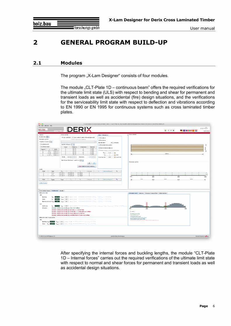
The module „CLT-Plate 1D – continuous beam” offers the required verifications for the ultimate limit state (ULS) with respect to bending and shear for permanent and transient loads as well as accidental (fire) design situations, and the verifications for the serviceability limit state with respect to deflection and vibrations according to EN 1990 or EN 1995 for continuous systems such as cross laminated timber plates.
After specifying the internal forces and buckling lengths, the module “CLT-Plate 1D – Internal forces” carries out the required verifications of the ultimate limit state with respect to normal and shear forces for permanent and transient loads as well as accidental design situations.
X-Lam Designer for Derix Cross Laminated Timber
User manual
Page 7
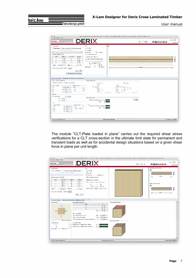
The module “CLT-Plate loaded in plane” carries out the required shear stress verifications for a CLT cross-section in the ultimate limit state for permanent and transient loads as well as for accidental design situations based on a given shear force in plane per unit length.
X-Lam Designer for Derix Cross Laminated Timber
User manual
Page 8
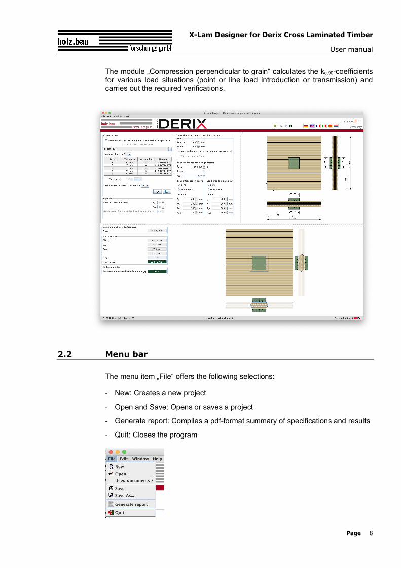
The module „Compression perpendicular to grain“ calculates the kc,90-coefficients for various load situations (point or line load introduction or transmission) and carries out the required verifications.
2.2 Menu bar
The menu item „File“ offers the following selections:
- New: Creates a new project
- Open and Save: Opens or saves a project
- Generate report: Compiles a pdf-format summary of specifications and results
- Quit: Closes the program
X-Lam Designer for Derix Cross Laminated Timber
User manual
Page 9
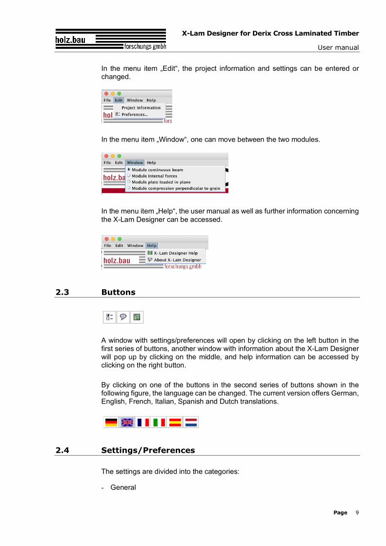
In the menu item „Edit“, the project information and settings can be entered or changed.
In the menu item „Window“, one can move between the two modules.
In the menu item „Help“, the user manual as well as further information concerning the X-Lam Designer can be accessed.
2.3 Buttons
A window with settings/preferences will open by clicking on the left button in the first series of buttons, another window with information about the X-Lam Designer will pop up by clicking on the middle, and help information can be accessed by clicking on the right button.
By clicking on one of the buttons in the second series of buttons shown in the following figure, the language can be changed. The current version offers German, English, French, Italian, Spanish and Dutch translations.
2.4 Settings/Preferences
The settings are divided into the categories:
- General
X-Lam Designer for Derix Cross Laminated Timber
User manual
Page 10
- Loads
- Analysis
- Verification
- Documentation
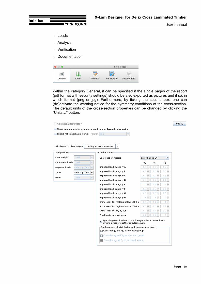
Within the category General, it can be specified if the single pages of the report (pdf format with security settings) should be also exported as pictures and if so, in which format (png or jpg). Furthermore, by ticking the second box, one can (de)activate the warning notice for the symmetry conditions of the cross-section. The default units of the cross-section properties can be changed by clicking the "Units…" button.
X-Lam Designer for Derix Cross Laminated Timber
User manual
Page 11
The settings regarding the type of calculation for the dead load, as well as the type of load position can be configured within the category Loads. The load combinations can be also adjusted here. As for the combination factors, they can be chosen according to EN or NA, but can be also user-defined. Furthermore, an option is offered here to simultaneously apply either snow load or wind actions together with the imposed load on roofs (category H). For the automatic generation of load combinations, it is also necessary to define whether the distributed and single loads should be considered as a one load group. This is due to differences which arise in combinations where the leading actions come from variable loads.
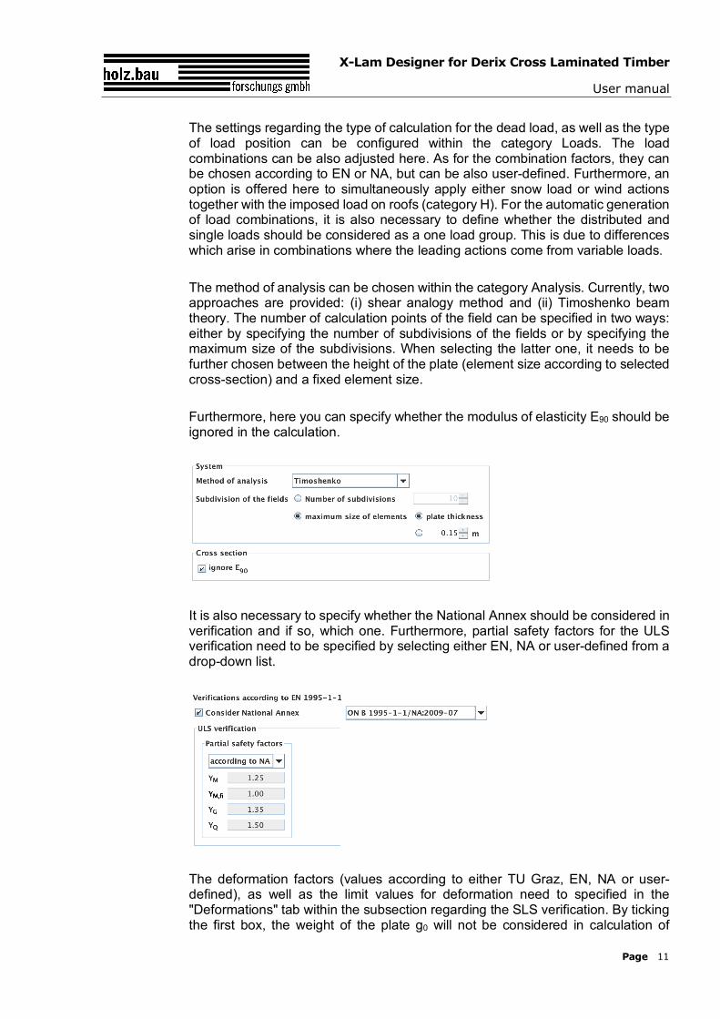
The method of analysis can be chosen within the category Analysis. Currently, two approaches are provided: (i) shear analogy method and (ii) Timoshenko beam theory. The number of calculation points of the field can be specified in two ways: either by specifying the number of subdivisions of the fields or by specifying the maximum size of the subdivisions. When selecting the latter one, it needs to be further chosen between the height of the plate (element size according to selected cross-section) and a fixed element size.
Furthermore, here you can specify whether the modulus of elasticity E90 should be ignored in the calculation.
It is also necessary to specify whether the National Annex should be considered in verification and if so, which one. Furthermore, partial safety factors for the ULS verification need to be specified by selecting either EN, NA or user-defined from a drop-down list.
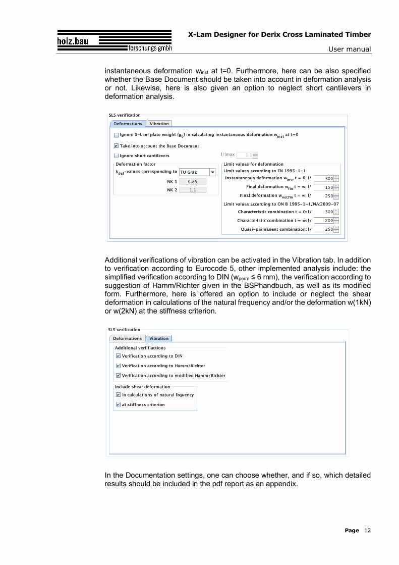
The deformation factors (values according to either TU Graz, EN, NA or user-defined), as well as the limit values for deformation need to specified in the "Deformations" tab within the subsection regarding the SLS verification. By ticking the first box, the weight of the plate g0 will not be considered in calculation of
X-Lam Designer for Derix Cross Laminated Timber
User manual
Page 12
instantaneous deformation winst at t=0. Furthermore, here can be also specified whether the Base Document should be taken into account in deformation analysis or not. Likewise, here is also given an option to neglect short cantilevers in deformation analysis.
Additional verifications of vibration can be activated in the Vibration tab. In addition to verification according to Eurocode 5, other implemented analysis include: the simplified verification according to DIN (wperm ≤ 6 mm), the verification according to suggestion of Hamm/Richter given in the BSPhandbuch, as well as its modified form. Furthermore, here is offered an option to include or neglect the shear deformation in calculations of the natural frequency and/or the deformation w(1kN) or w(2kN) at the stiffness criterion.
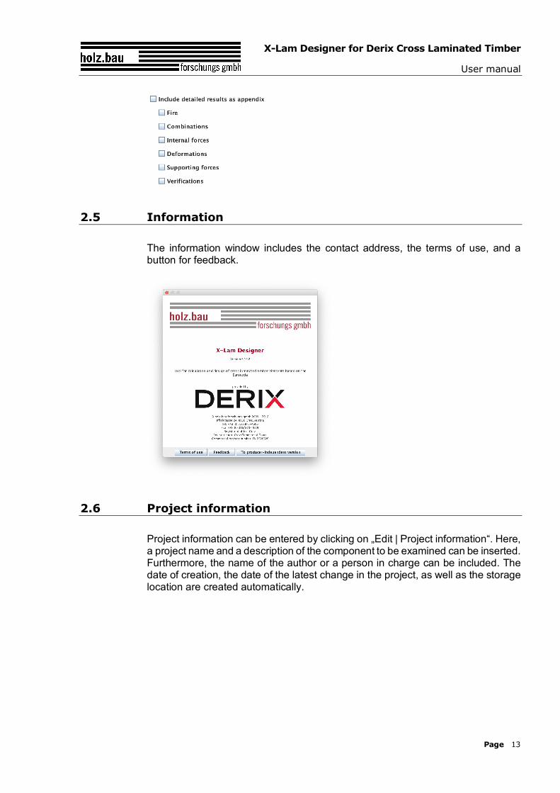
In the Documentation settings, one can choose whether, and if so, which detailed results should be included in the pdf report as an appendix.
X-Lam Designer for Derix Cross Laminated Timber
User manual
Page 13
2.5 Information
The information window includes the contact address, the terms of use, and a button for feedback.
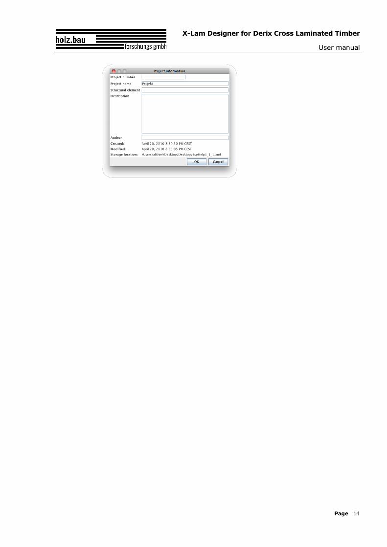
2.6 Project information
Project information can be entered by clicking on „Edit | Project information“. Here, a project name and a description of the component to be examined can be inserted. Furthermore, the name of the author or a person in charge can be included. The date of creation, the date of the latest change in the project, as well as the storage location are created automatically.
X-Lam Designer for Derix Cross Laminated Timber
User manual
Page 14
X-Lam Designer for Derix Cross Laminated Timber
User manual
Page 15
3 MODULE „CLT-PLATE 1D – CONTINUOUS BEAM“
3.1 Input information
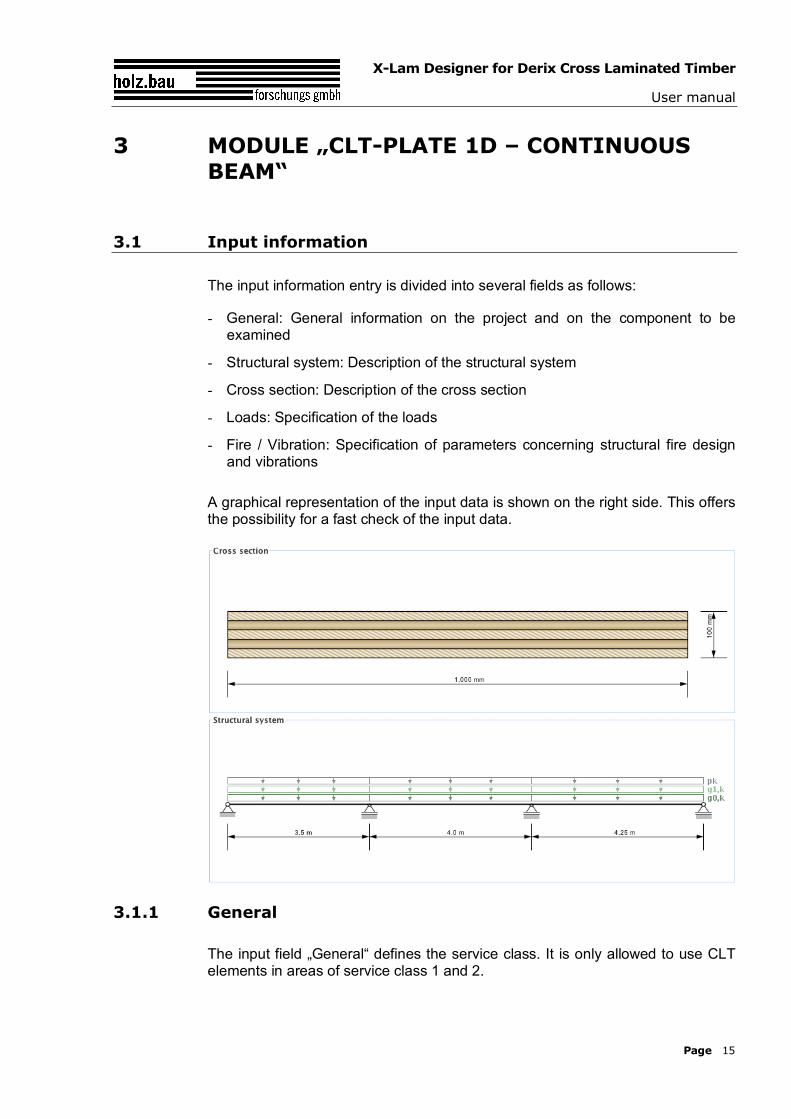
The input information entry is divided into several fields as follows:
- General: General information on the project and on the component to be examined
- Structural system: Description of the structural system
- Cross section: Description of the cross section
- Loads: Specification of the loads
- Fire / Vibration: Specification of parameters concerning structural fire design and vibrations
A graphical representation of the input data is shown on the right side. This offers the possibility for a fast check of the input data.
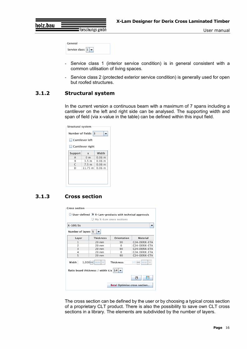
3.1.1 General
The input field „General“ defines the service class. It is only allowed to use CLT elements in areas of service class 1 and 2.
X-Lam Designer for Derix Cross Laminated Timber
User manual
Page 16
- Service class 1 (interior service condition) is in general consistent with a common utilisation of living spaces.
- Service class 2 (protected exterior service condition) is generally used for open but roofed structures.
3.1.2 Structural system
In the current version a continuous beam with a maximum of 7 spans including a cantilever on the left and right side can be analysed. The supporting width and span of field (via x-value in the table) can be defined within this input field.
3.1.3 Cross section
The cross section can be defined by the user or by choosing a typical cross section of a proprietary CLT product. There is also the possibility to save own CLT cross sections in a library. The elements are subdivided by the number of layers.
X-Lam Designer for Derix Cross Laminated Timber
User manual
Page 17
If a user-defined cross section is entered, the thickness and orientation of each layer can be changed. Furthermore, the material can be changed for all layers. The thickness of each layer has to be within the range of 6.0 mm to 45 mm. In the case of proprietary CLT products, the strength class of lumber and the orientation can be changed. If the orientation is changed, the whole cross section is rotated.
The width of the CLT plate strips can be also defined in this field. The default value is set to 1 m. The thickness of the CLT plate is calculated automatically based on the thickness of the single layers.
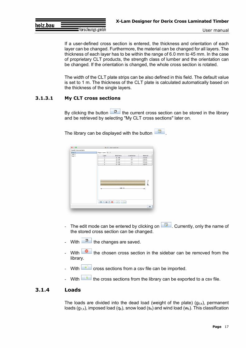
3.1.3.1 My CLT cross sections
By clicking the button the current cross section can be stored in the library and be retrieved by selecting "My CLT cross sections" later on.
The library can be displayed with the button .
- The edit mode can be entered by clicking on . Currently, only the name of the stored cross section can be changed.
- With the changes are saved.
- With the chosen cross section in the sidebar can be removed from the library.
- With cross sections from a csv file can be imported.
- With the cross sections from the library can be exported to a csv file.
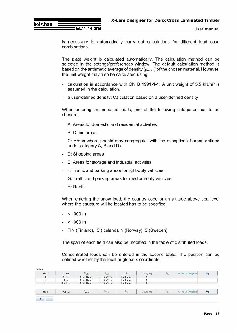
3.1.4 Loads
The loads are divided into the dead load (weight of the plate) (g0,k), permanent loads (g1,k), imposed load (qk), snow load (sk) and wind load (wk). This classification
X-Lam Designer for Derix Cross Laminated Timber
User manual
Page 18
is necessary to automatically carry out calculations for different load case combinations.
The plate weight is calculated automatically. The calculation method can be selected in the settings/preferences window. The default calculation method is based on the arithmetic average of density (ρmean) of the chosen material. However, the unit weight may also be calculated using:
- calculation in accordance with ON B 1991-1-1. A unit weight of 5.5 kN/m³ is assumed in the calculation.
- a user-defined density: Calculation based on a user-defined density
When entering the imposed loads, one of the following categories has to be chosen:
- A: Areas for domestic and residential activities
- B: Office areas
- C: Areas where people may congregate (with the exception of areas defined under category A, B and D)
- D: Shopping areas
- E: Areas for storage and industrial activities
- F: Traffic and parking areas for light-duty vehicles
- G: Traffic and parking areas for medium-duty vehicles
- H: Roofs
When entering the snow load, the country code or an altitude above sea level where the structure will be located has to be specified:
- < 1000 m
- > 1000 m
- FIN (Finland), IS (Iceland), N (Norway), S (Sweden)
The span of each field can also be modified in the table of distributed loads.
Concentrated loads can be entered in the second table. The position can be defined whether by the local or global x-coordinate.
X-Lam Designer for Derix Cross Laminated Timber
User manual
Page 19
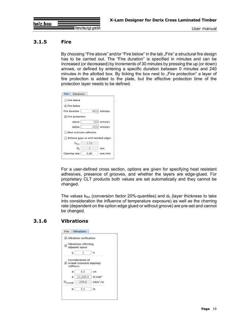
3.1.5 Fire
By choosing “Fire above” and/or “Fire below” in the tab „Fire“ a structural fire design has to be carried out. The “Fire duration” is specified in minutes and can be increased (or decreased) by increments of 30 minutes by pressing the up (or down) arrows, or defined by entering a specific duration between 0 minutes and 240 minutes in the allotted box. By ticking the box next to „Fire protection“ a layer of fire protection is added to the plate, but the effective protection time of the protection layer needs to be defined.
For a user-defined cross section, options are given for specifying heat resistant adhesives, presence of grooves, and whether the layers are edge-glued. For proprietary CLT products both values are set automatically and they cannot be changed.
The values kfire (conversion factor 20%-quantiles) and d0 (layer thickness to take into consideration the influence of temperature exposure) as well as the charring rate (dependent on the option edge glued or without groove) are pre-set and cannot be changed.
3.1.6 Vibrations
X-Lam Designer for Derix Cross Laminated Timber
User manual
Page 20
The tab „Vibrations“ allows for vibration verification.
For the vibration verification the following specifications are of importance:
- Vibrations affecting adjacent span: Is it detrimental if vibrations are transferred to neighboring fields?
- Modal damping factor
- Consideration of the screed (concrete topping) stiffness: Is the stiffness of the screed (concrete topping) taken into consideration?
- Thickness of the screed (concrete topping)
- Modulus of elasticity of the screed (concrete topping)
- support (2-sided or 4-sided)
- room width b perpendicular to the load carrying direction
The effective width bw of the chosen cross section used by the stiffness criteria will be specified.
3.2 Results and output
Load combinations are compiled based on the input loads entered in the “Loads” field. The respective kmod- and kdef-values can be determined automatically based on the classification of loads (plate weight, wind load, etc.).
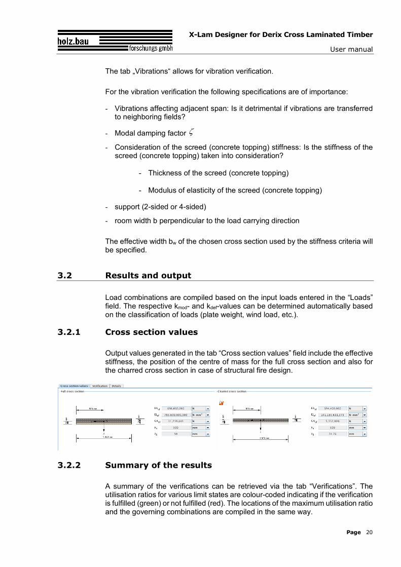
3.2.1 Cross section values
Output values generated in the tab “Cross section values” field include the effective stiffness, the position of the centre of mass for the full cross section and also for the charred cross section in case of structural fire design.
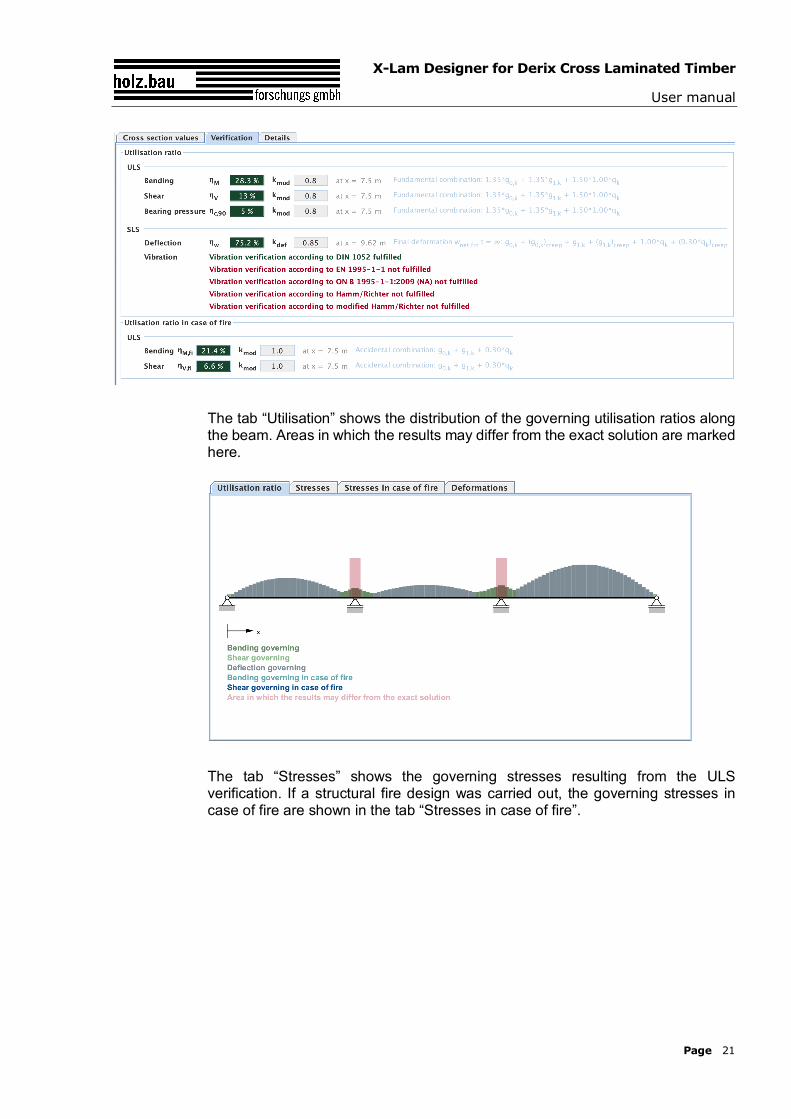
3.2.2 Summary of the results
A summary of the verifications can be retrieved via the tab “Verifications”. The utilisation ratios for various limit states are colour-coded indicating if the verification is fulfilled (green) or not fulfilled (red). The locations of the maximum utilisation ratio and the governing combinations are compiled in the same way.
z
X-Lam Designer for Derix Cross Laminated Timber
User manual
Page 21
The tab “Utilisation” shows the distribution of the governing utilisation ratios along the beam. Areas in which the results may differ from the exact solution are marked here.
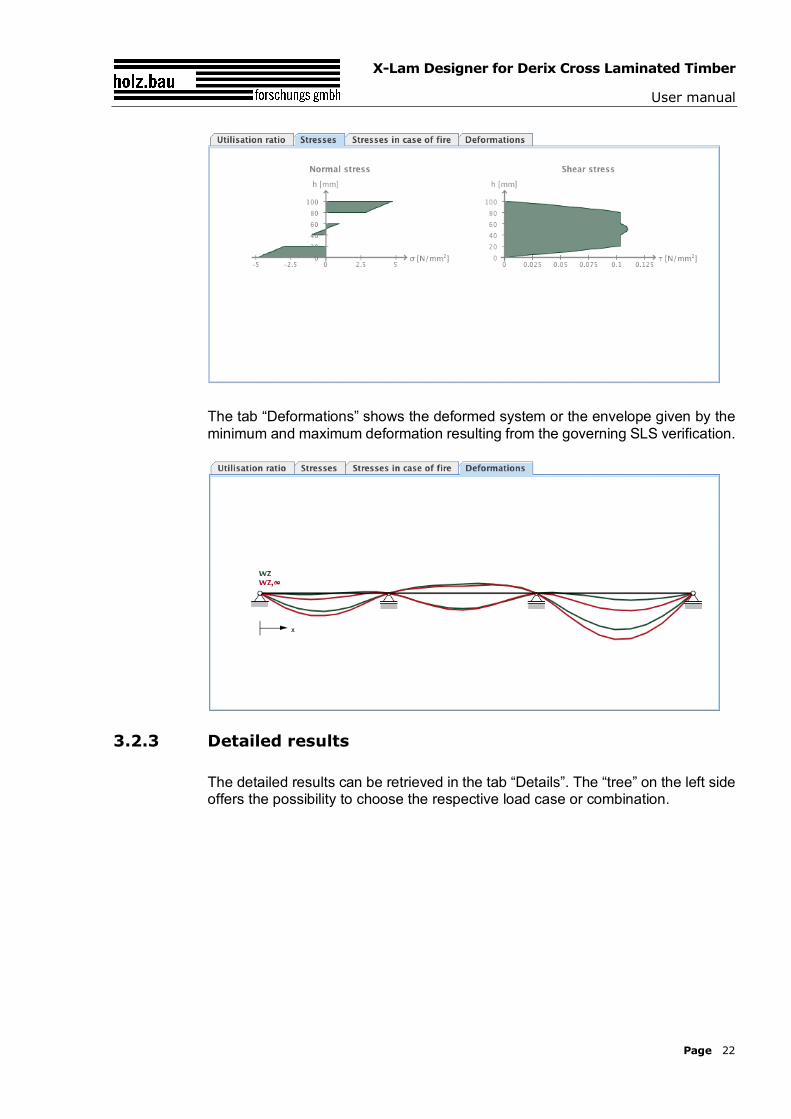
The tab “Stresses” shows the governing stresses resulting from the ULS verification. If a structural fire design was carried out, the governing stresses in case of fire are shown in the tab “Stresses in case of fire”.
X-Lam Designer for Derix Cross Laminated Timber
User manual
Page 22
The tab “Deformations” shows the deformed system or the envelope given by the minimum and maximum deformation resulting from the governing SLS verification.
3.2.3 Detailed results
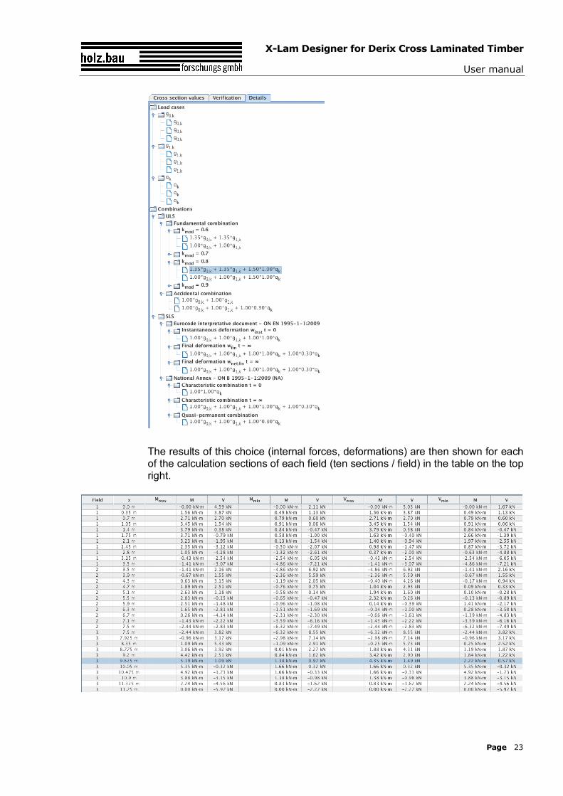
The detailed results can be retrieved in the tab “Details”. The “tree” on the left side offers the possibility to choose the respective load case or combination.
X-Lam Designer for Derix Cross Laminated Timber
User manual
Page 23
The results of this choice (internal forces, deformations) are then shown for each of the calculation sections of each field (ten sections / field) in the table on the top right.
X-Lam Designer for Derix Cross Laminated Timber
User manual
Page 24
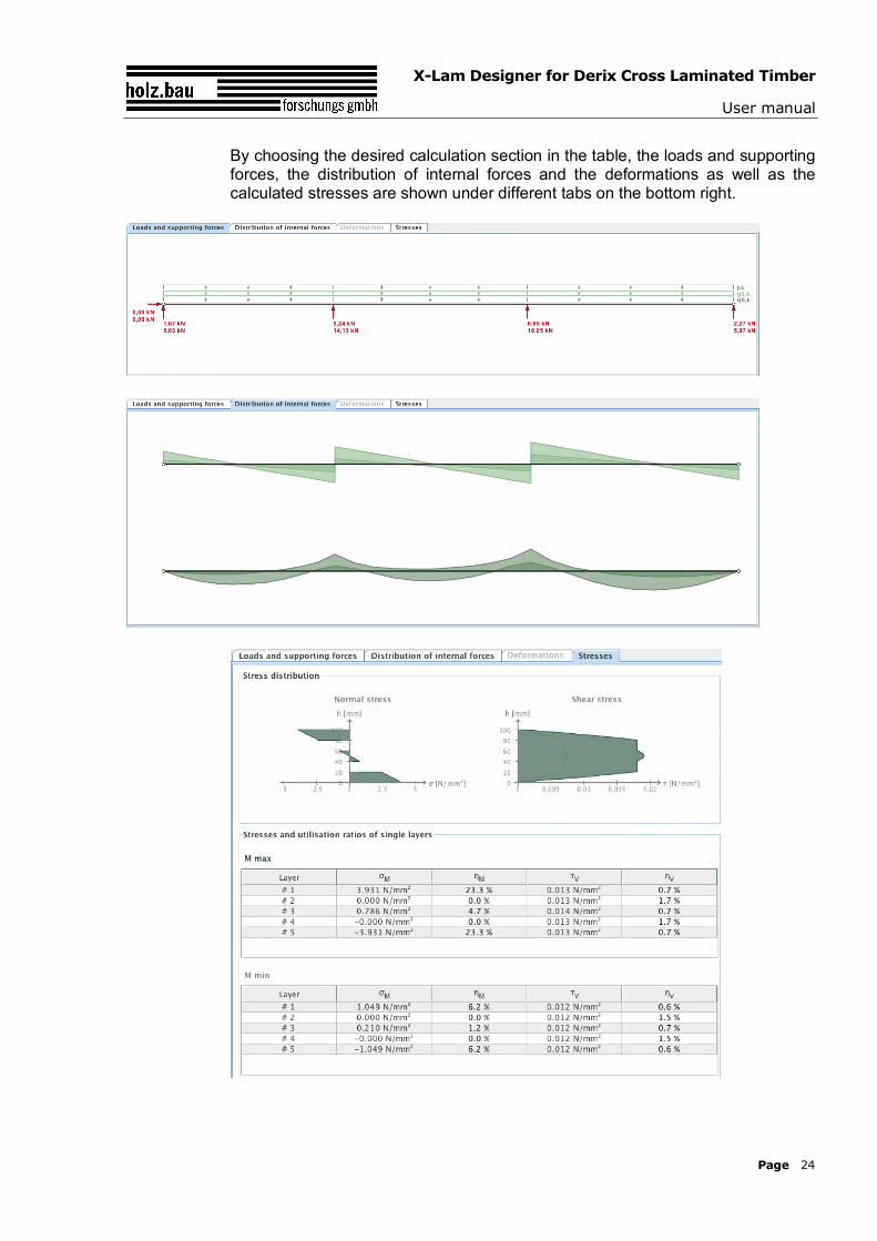
By choosing the desired calculation section in the table, the loads and supporting forces, the distribution of internal forces and the deformations as well as the calculated stresses are shown under different tabs on the bottom right.
X-Lam Designer for Derix Cross Laminated Timber
User manual
Page 25
4 MODULE „CLT-PLATE 1D – INTERNAL FORCES“
4.1 Input data
The input data include:
- Cross section: Definition of the cross section
- Fire: Specifications concerning structural fire design
- Internal forces: According to the theory (of 1st or 2nd order) on which the calculations are based on
- Design factors
- Stability: Specifications concerning stability
4.1.1 Cross section
See 3.1.3
4.1.2 Fire
See 3.1.5
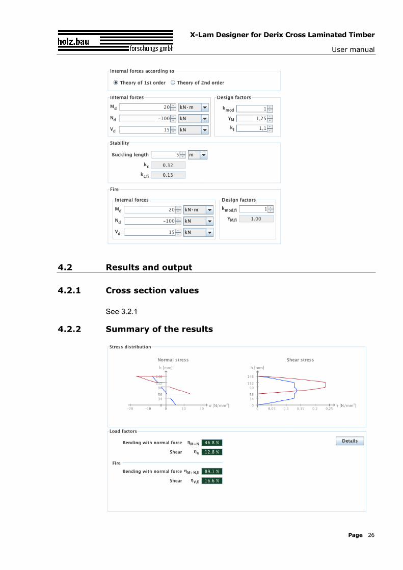
4.1.3 Type of calculation, internal forces, design factors and specifications concerning stability
The internal forces and the underlying type of calculation are defined in the tab „Internal forces, stresses and utilisation ratios“. Additionally, the design values are specified here.
If the internal forces result from a calculation based on a first order analysis a substitute buckling length has to be stated in case of a negative normal force („problem of stability“). Based on this buckling length and the respective cross section the required buckling factor kc needed for the verification is calculated automatically.
X-Lam Designer for Derix Cross Laminated Timber
User manual
Page 26
4.2 Results and output
4.2.1 Cross section values
See 3.2.1
4.2.2 Summary of the results
X-Lam Designer for Derix Cross Laminated Timber
User manual
Page 27
The stress distributions and the governing utilisation ratios are shown in the tab „Internal forces, stresses and utilisation ratios“.
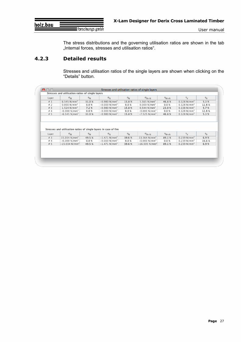
4.2.3 Detailed results
Stresses and utilisation ratios of the single layers are shown when clicking on the “Details” button.
X-Lam Designer for Derix Cross Laminated Timber
User manual
Page 28
5 MODULE „CLT-PLATE LOADED IN PLANE“
5.1 Input information
The input information entry is divided into several fields as follows:
- Definition of the cross section
- Information concerning structural fire design
- Internal force variables
- Design factors
5.1.1 Cross section
See Fehler! Verweisquelle konnte nicht gefunden werden.
In this module it is not possible to change the cross sectional width.
5.1.2 Fire
See Fehler! Verweisquelle konnte nicht gefunden werden.
Fire left / right instead of fire above and below.
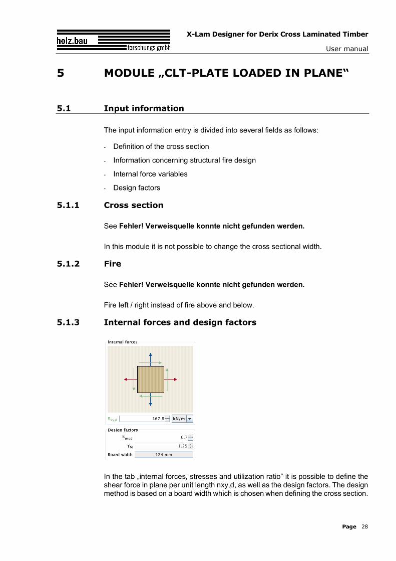
5.1.3 Internal forces and design factors
In the tab „internal forces, stresses and utilization ratio“ it is possible to define the shear force in plane per unit length nxy,d, as well as the design factors. The design method is based on a board width which is chosen when defining the cross section.
X-Lam Designer for Derix Cross Laminated Timber
User manual
Page 29
5.2 Results and output
5.2.1 Cross section values
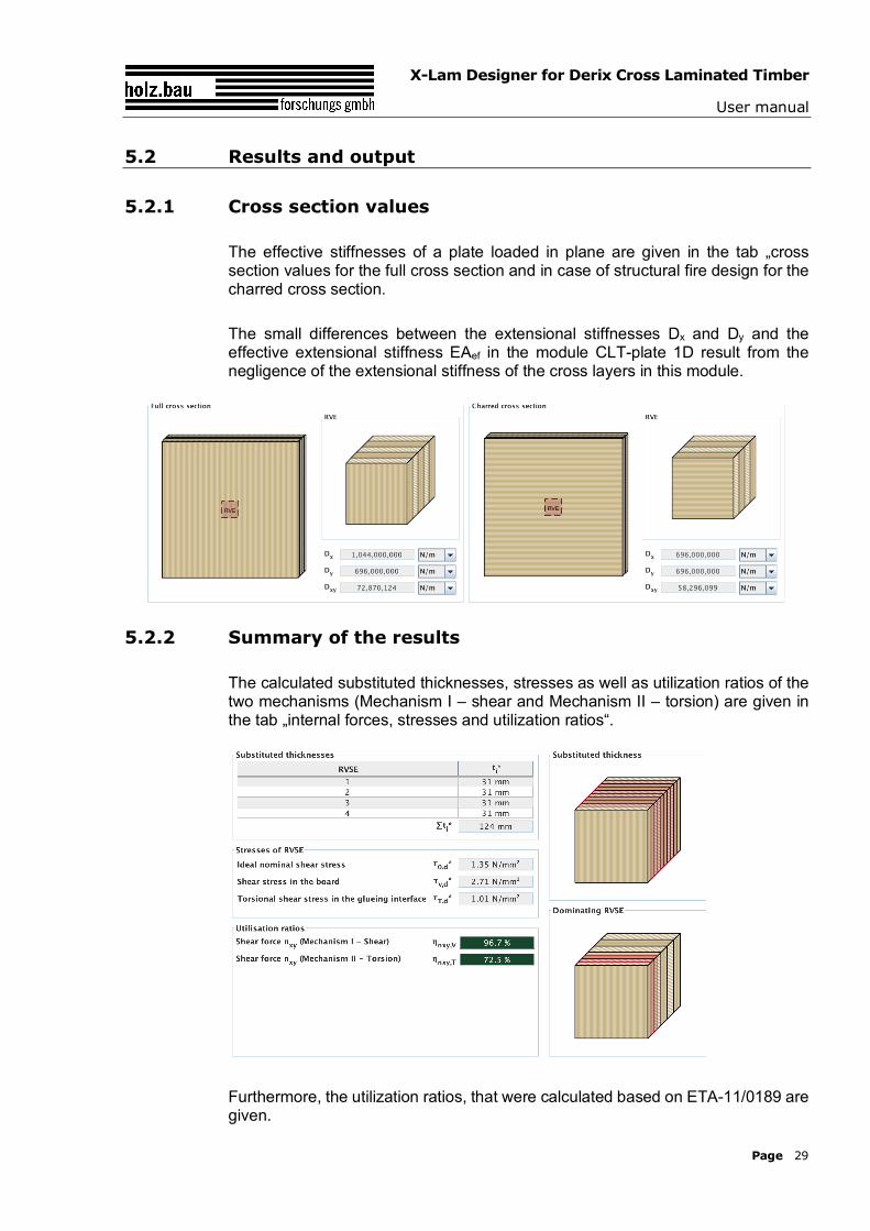
The effective stiffnesses of a plate loaded in plane are given in the tab „cross section values for the full cross section and in case of structural fire design for the charred cross section.
The small differences between the extensional stiffnesses Dx and Dy and the effective extensional stiffness EAef in the module CLT-plate 1D result from the negligence of the extensional stiffness of the cross layers in this module.
5.2.2 Summary of the results
The calculated substituted thicknesses, stresses as well as utilization ratios of the two mechanisms (Mechanism I – shear and Mechanism II – torsion) are given in the tab „internal forces, stresses and utilization ratios“.
Furthermore, the utilization ratios, that were calculated based on ETA-11/0189 are given.
X-Lam Designer for Derix Cross Laminated Timber
User manual
Page 30
6 MODULE „ COMPRESSION PERPENDICULAR TO GRAIN“
6.1 Input information
The input is divided into:
- definitions of the cross section
- definitions of the plate dimensions
- input of the loads
- type of load configuration
- calculation options
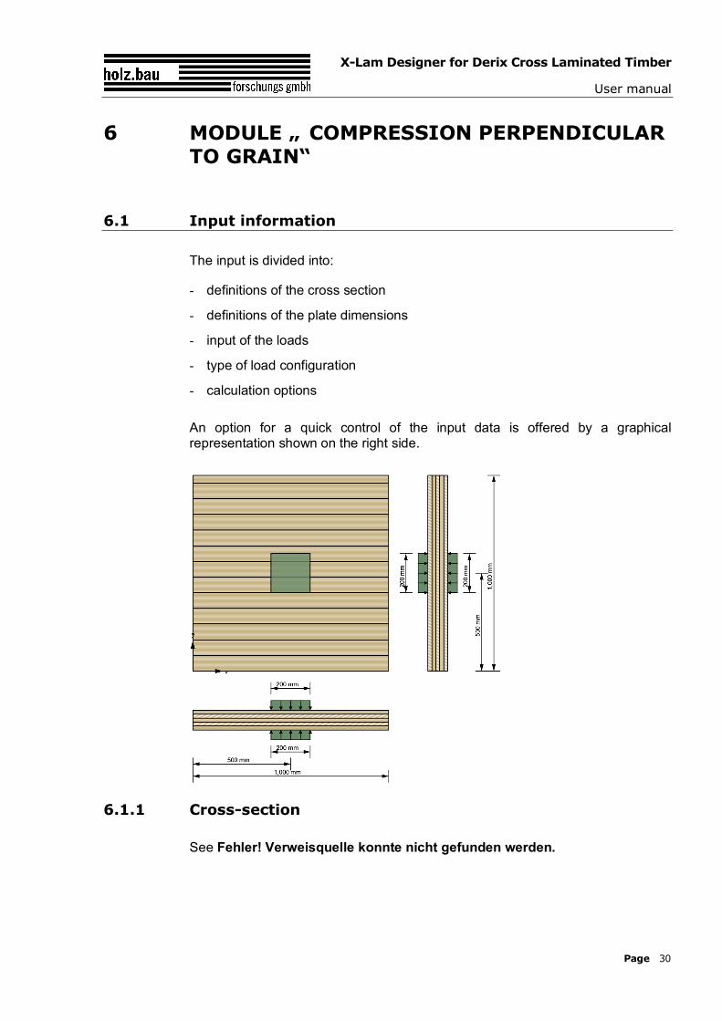
An option for a quick control of the input data is offered by a graphical representation shown on the right side.
6.1.1 Cross-section
See Fehler! Verweisquelle konnte nicht gefunden werden.
X-Lam Designer for Derix Cross Laminated Timber
User manual
Page 31
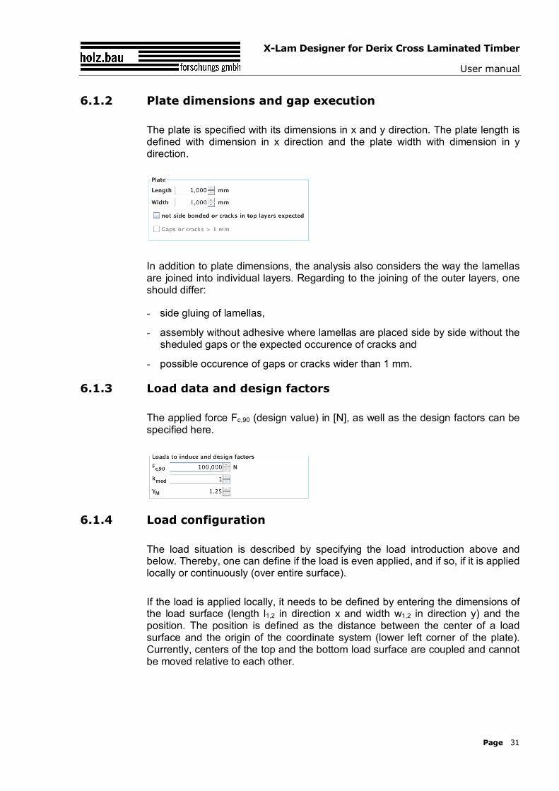
6.1.2 Plate dimensions and gap execution
The plate is specified with its dimensions in x and y direction. The plate length is defined with dimension in x direction and the plate width with dimension in y direction.
In addition to plate dimensions, the analysis also considers the way the lamellas are joined into individual layers. Regarding to the joining of the outer layers, one should differ:
- side gluing of lamellas,
- assembly without adhesive where lamellas are placed side by side without the sheduled gaps or the expected occurence of cracks and
- possible occurence of gaps or cracks wider than 1 mm.
6.1.3 Load data and design factors
The applied force Fc,90 (design value) in [N], as well as the design factors can be specified here.
6.1.4 Load configuration
The load situation is described by specifying the load introduction above and below. Thereby, one can define if the load is even applied, and if so, if it is applied locally or continuously (over entire surface).
If the load is applied locally, it needs to be defined by entering the dimensions of the load surface (length l1,2 in direction x and width w1,2 in direction y) and the position. The position is defined as the distance between the center of a load surface and the origin of the coordinate system (lower left corner of the plate). Currently, centers of the top and the bottom load surface are coupled and cannot be moved relative to each other.
X-Lam Designer for Derix Cross Laminated Timber
User manual
Page 32
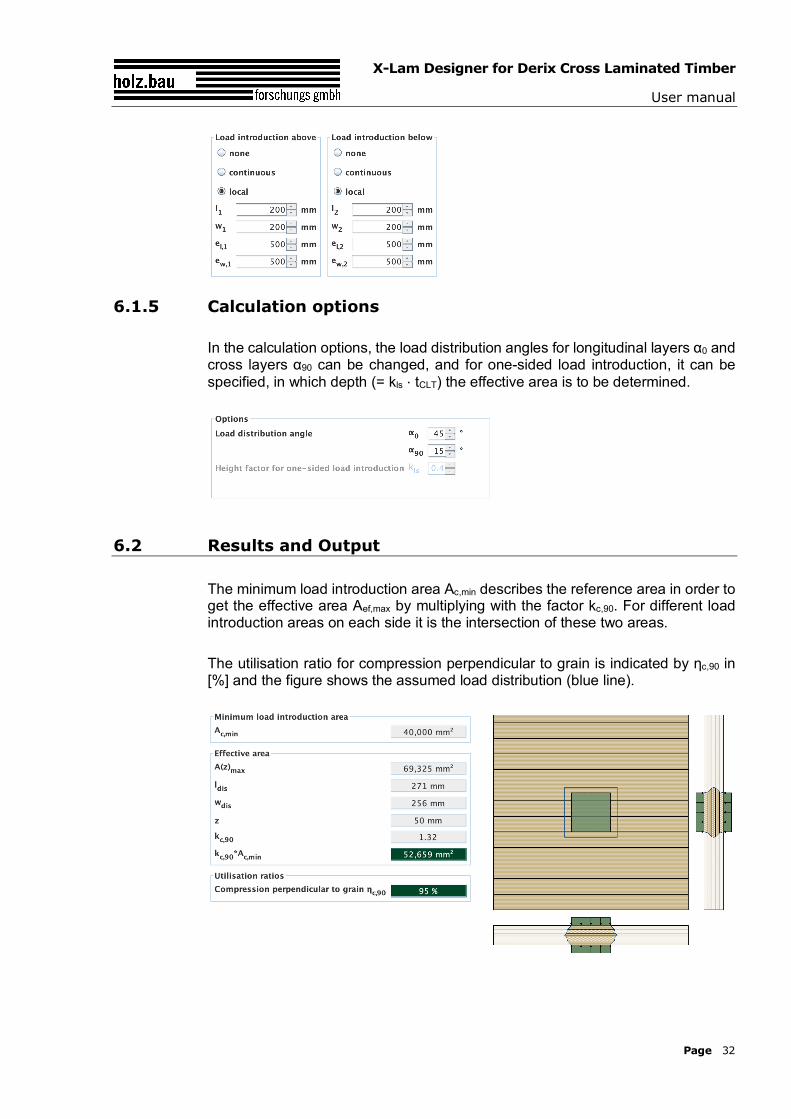
6.1.5 Calculation options
In the calculation options, the load distribution angles for longitudinal layers α0 and cross layers α90 can be changed, and for one-sided load introduction, it can be specified, in which depth (= kls ⋅ tCLT) the effective area is to be determined.
6.2 Results and Output
The minimum load introduction area Ac,min describes the reference area in order to get the effective area Aef,max by multiplying with the factor kc,90. For different load introduction areas on each side it is the intersection of these two areas.
The utilisation ratio for compression perpendicular to grain is indicated by ηc,90 in [%] and the figure shows the assumed load distribution (blue line).
X-Lam Designer for Derix Cross Laminated Timber
User manual
Page 33
7 CONTACT
Address: holz.bau forschungs gmbh Inffeldgasse 24 8010 Graz Austria
Internet: www.cltdesigner.at www.cltdesigner.com
E-Mail: [email protected]
![Innovatives Holz-Holz- Verbindungssystem für Brettsperrholz · DERIX X-LAM [1] und BSPhandbuch [2]) 2.1.3. Kontaktfuge Wand-Wand-T (WWT) Ein T-Stoß wird erforderlich, wenn eine](https://img.pdfslide.us/doc/110x75/60c377a92b33c7358344eab6/innovatives-holz-holz-verbindungssystem-fr-brettsperrholz-derix-x-lam-1-und.jpg)