Embed Size (px)
Citation preview

5WM-28199-E5
XJR1300
OWNER’S MANUAL
EAU26944
DECLARATION of CONFORMITY
YAMAHAMOTOR ELECTRONICS CO., LTD.
1450-6, Mori, Mori-machi, Shuchi-gun, Shizuoka-ken, 437-0292 Japan
General manager of quality assurance div.
1Version up the norm of EN60950 to EN60950-1 To change company name
27 Feb. 20061 Mar. 2007
23
Revision recordNo. Contents Date
To change contact person and integrate type-designation. 9 Jun. 2005
Date of issue: 1 Aug. 2002
Place of issue: Shizuoka, Japan
R&TTE Directive(1999/5/EC)EN300 330-2 v1.1.1(2001-6), EN60950-1(2001)Two or Three-Wheel Motor Vehicles Directive(97/24/EC: Chapter 8, EMC)
is in compliance with following norm(s) or documents:
Kind of equipment: IMMOBILIZERType-designation: 5SL-00
Hereby declare that the product:
Company: YAMAHA MOTOR ELECTRONICS CO., LTD.Address: 1450-6, Mori, Mori-Machi, Shuchi-gun, Shizuoka-Ken, 437-0292 Japan
We
U5WME5E0.book Page 1 Wednesday, December 5, 2007 10:30 AM
INTRODUCTIONEAU10100
Welcome to the Yamaha world of motorcycling!As the owner of the XJR1300, you are benefiting from Yamaha’s vast experience and newest technology regarding the de-sign and manufacture of high-quality products, which have earned Yamaha a reputation for dependability.Please take the time to read this manual thoroughly, so as to enjoy all advantages of your XJR1300. The owner’s manualdoes not only instruct you in how to operate, inspect and maintain your motorcycle, but also in how to safeguard yourself andothers from trouble and injury.In addition, the many tips given in this manual will help keep your motorcycle in the best possible condition. If you have anyfurther questions, do not hesitate to contact your Yamaha dealer.The Yamaha team wishes you many safe and pleasant rides. So, remember to put safety first!
U5WME5E0.book Page 1 Wednesday, December 5, 2007 10:30 AM
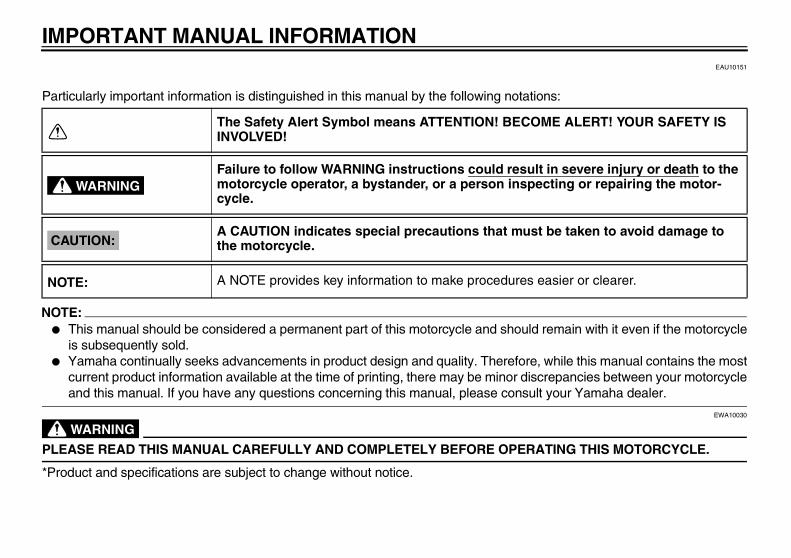
IMPORTANT MANUAL INFORMATIONEAU10151
Particularly important information is distinguished in this manual by the following notations:
NOTE:� This manual should be considered a permanent part of this motorcycle and should remain with it even if the motorcycle
is subsequently sold.� Yamaha continually seeks advancements in product design and quality. Therefore, while this manual contains the most
current product information available at the time of printing, there may be minor discrepancies between your motorcycleand this manual. If you have any questions concerning this manual, please consult your Yamaha dealer.
WARNINGEWA10030
PLEASE READ THIS MANUAL CAREFULLY AND COMPLETELY BEFORE OPERATING THIS MOTORCYCLE.
*Product and specifications are subject to change without notice.
The Safety Alert Symbol means ATTENTION! BECOME ALERT! YOUR SAFETY IS INVOLVED!
Failure to follow WARNING instructions could result in severe injury or death to the motorcycle operator, a bystander, or a person inspecting or repairing the motor-cycle.
A CAUTION indicates special precautions that must be taken to avoid damage to the motorcycle.
A NOTE provides key information to make procedures easier or clearer.
WARNING
CAUTION:
NOTE:
U5WME5E0.book Page 1 Wednesday, December 5, 2007 10:30 AM
IMPORTANT MANUAL INFORMATION
EAU10200
XJR1300OWNER’S MANUAL
©2007 by Yamaha Motor Co., Ltd.1st edition, November 2007
All rights reserved.Any reprinting or unauthorized use without the written permission of
Yamaha Motor Co., Ltd. is expressly prohibited.
Printed in Japan.
U5WME5E0.book Page 2 Wednesday, December 5, 2007 10:30 AM
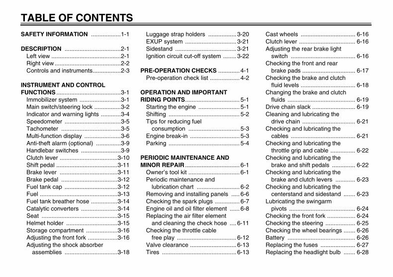
TABLE OF CONTENTSSAFETY INFORMATION ..................1-1
DESCRIPTION ..................................2-1Left view ..........................................2-1Right view ........................................2-2Controls and instruments.................2-3
INSTRUMENT AND CONTROL FUNCTIONS .......................................3-1
Immobilizer system .........................3-1Main switch/steering lock ................3-2Indicator and warning lights ............3-4Speedometer ..................................3-5Tachometer ....................................3-5Multi-function display ......................3-6Anti-theft alarm (optional) ...............3-9Handlebar switches ........................3-9Clutch lever ...................................3-10Shift pedal .....................................3-11Brake lever ...................................3-11Brake pedal ..................................3-12Fuel tank cap ................................3-12Fuel ...............................................3-13Fuel tank breather hose ................3-14Catalytic converters ......................3-14Seat ..............................................3-15Helmet holder ...............................3-15Storage compartment ...................3-16Adjusting the front fork ..................3-16Adjusting the shock absorber
assemblies ................................3-18
Luggage strap holders ................. 3-20EXUP system ............................... 3-21Sidestand ..................................... 3-21Ignition circuit cut-off system ........ 3-22
PRE-OPERATION CHECKS ............. 4-1Pre-operation check list .................. 4-2
OPERATION AND IMPORTANT RIDING POINTS................................. 5-1
Starting the engine ......................... 5-1Shifting ........................................... 5-2Tips for reducing fuel
consumption ............................... 5-3Engine break-in .............................. 5-3Parking ........................................... 5-4
PERIODIC MAINTENANCE AND MINOR REPAIR ................................. 6-1
Owner’s tool kit ............................... 6-1Periodic maintenance and
lubrication chart .......................... 6-2Removing and installing panels ..... 6-6Checking the spark plugs ............... 6-7Engine oil and oil filter element ...... 6-8Replacing the air filter element
and cleaning the check hose .... 6-11Checking the throttle cable
free play .................................... 6-12Valve clearance ............................ 6-13Tires ............................................. 6-13
Cast wheels ................................. 6-16Clutch lever .................................. 6-16Adjusting the rear brake light
switch ....................................... 6-16Checking the front and rear
brake pads ................................ 6-17Checking the brake and clutch
fluid levels ................................. 6-18Changing the brake and clutch
fluids ......................................... 6-19Drive chain slack .......................... 6-19Cleaning and lubricating the
drive chain ................................ 6-21Checking and lubricating the
cables ....................................... 6-21Checking and lubricating the
throttle grip and cable ............... 6-22Checking and lubricating the
brake and shift pedals .............. 6-22Checking and lubricating the
brake and clutch levers ............ 6-23Checking and lubricating the
centerstand and sidestand ....... 6-23Lubricating the swingarm
pivots ........................................ 6-24Checking the front fork ................. 6-24Checking the steering .................. 6-25Checking the wheel bearings ....... 6-26Battery ......................................... 6-26Replacing the fuses ..................... 6-27Replacing the headlight bulb ....... 6-28
U5WME5E0.book Page 1 Wednesday, December 5, 2007 10:30 AM
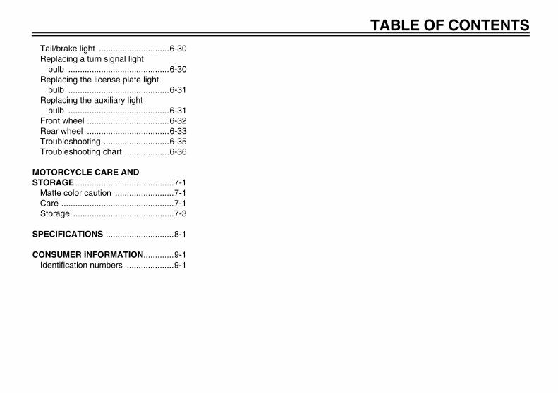
TABLE OF CONTENTSTail/brake light ..............................6-30Replacing a turn signal light
bulb ...........................................6-30Replacing the license plate light
bulb ...........................................6-31Replacing the auxiliary light
bulb ...........................................6-31Front wheel ...................................6-32Rear wheel ...................................6-33Troubleshooting ............................6-35Troubleshooting chart ...................6-36
MOTORCYCLE CARE AND STORAGE ..........................................7-1
Matte color caution .........................7-1Care ................................................7-1Storage ...........................................7-3
SPECIFICATIONS .............................8-1
CONSUMER INFORMATION.............9-1Identification numbers ....................9-1
U5WME5E0.book Page 2 Wednesday, December 5, 2007 10:30 AM
1-1
1
SAFETY INFORMATION EAU10281
MOTORCYCLES ARE SINGLETRACK VEHICLES. THEIR SAFE USEAND OPERATION ARE DEPENDENTUPON THE USE OF PROPER RIDINGTECHNIQUES AS WELL AS THE EX-PERTISE OF THE OPERATOR. EV-ERY OPERATOR SHOULD KNOWTHE FOLLOWING REQUIREMENTSBEFORE RIDING THIS MOTOR-CYCLE.HE OR SHE SHOULD:
� OBTAIN THOROUGH INSTRUC-TIONS FROM A COMPETENTSOURCE ON ALL ASPECTS OFMOTORCYCLE OPERATION.
� OBSERVE THE WARNINGS ANDMAINTENANCE REQUIRE-MENTS IN THE OWNER’S MAN-UAL.
� OBTAIN QUALIFIED TRAININGIN SAFE AND PROPER RIDINGTECHNIQUES.
� OBTAIN PROFESSIONAL TECH-NICAL SERVICE AS INDICATEDBY THE OWNER’S MANUAL
AND/OR WHEN MADE NECES-SARY BY MECHANICAL CONDI-TIONS.
Safe riding� Always make pre-operation
checks. Careful checks may helpprevent an accident.
� This motorcycle is designed to car-ry the operator and a passenger.
� The failure of motorists to detectand recognize motorcycles in traf-fic is the predominating cause ofautomobile/motorcycle accidents.Many accidents have been causedby an automobile driver who didnot see the motorcycle. Makingyourself conspicuous appears tobe very effective in reducing thechance of this type of accident.Therefore:• Wear a brightly colored jacket.• Use extra caution when you are
approaching and passingthrough intersections, since in-tersections are the most likelyplaces for motorcycle accidentsto occur.
• Ride where other motorists cansee you. Avoid riding in anothermotorist’s blind spot.
� Many accidents involve inexperi-enced operators. In fact, many op-erators who have been involved inaccidents do not even have a cur-rent motorcycle license.• Make sure that you are qualified
and that you only lend yourmotorcycle to other qualified op-erators.
• Know your skills and limits.Staying within your limits mayhelp you to avoid an accident.
• We recommend that you prac-tice riding your motorcyclewhere there is no traffic until youhave become thoroughly famil-iar with the motorcycle and all ofits controls.
� Many accidents have been causedby error of the motorcycle opera-tor. A typical error made by the op-erator is veering wide on a turn
U5WME5E0.book Page 1 Wednesday, December 5, 2007 10:30 AM
SAFETY INFORMATION
1-2
1
due to EXCESSIVE SPEED or un-dercornering (insufficient lean an-gle for the speed).• Always obey the speed limit and
never travel faster than warrant-ed by road and traffic conditions.
• Always signal before turning orchanging lanes. Make sure thatother motorists can see you.
� The posture of the operator andpassenger is important for propercontrol.• The operator should keep both
hands on the handlebar andboth feet on the operator foot-rests during operation to main-tain control of the motorcycle.
• The passenger should alwayshold onto the operator, the seatstrap or grab bar, if equipped,with both hands and keep bothfeet on the passenger footrests.
• Never carry a passenger unlesshe or she can firmly place bothfeet on the passenger footrests.
� Never ride under the influence ofalcohol or other drugs.
� This motorcycle is designed for on-road use only. It is not suitable foroff-road use.
Protective apparelThe majority of fatalities from motor-cycle accidents are the result of headinjuries. The use of a safety helmet isthe single most critical factor in the pre-vention or reduction of head injuries.
� Always wear an approved helmet.� Wear a face shield or goggles.
Wind in your unprotected eyescould contribute to an impairmentof vision that could delay seeing ahazard.
� The use of a jacket, heavy boots,trousers, gloves, etc., is effective inpreventing or reducing abrasionsor lacerations.
� Never wear loose-fitting clothes,otherwise they could catch on thecontrol levers, footrests, or wheelsand cause injury or an accident.
� Never touch the engine or exhaustsystem during or after operation.They become very hot and can
cause burns. Always wear protec-tive clothing that covers your legs,ankles, and feet.
� A passenger should also observethe above precautions.
ModificationsModifications made to this motorcyclenot approved by Yamaha, or the re-moval of original equipment, may ren-der the motorcycle unsafe for use andmay cause severe personal injury.Modifications may also make yourmotorcycle illegal to use.
Loading and accessoriesAdding accessories or cargo to yourmotorcycle can adversely affect stabili-ty and handling if the weight distributionof the motorcycle is changed. To avoidthe possibility of an accident, use ex-treme caution when adding cargo oraccessories to your motorcycle. Useextra care when riding a motorcyclethat has added cargo or accessories.Here are some general guidelines tofollow if loading cargo or adding acces-sories to your motorcycle:
U5WME5E0.book Page 2 Wednesday, December 5, 2007 10:30 AM
SAFETY INFORMATION
1-3
1
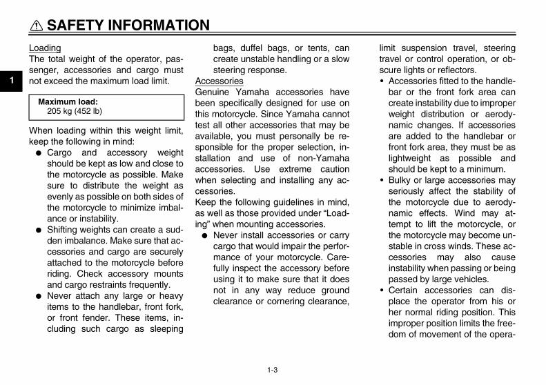
LoadingThe total weight of the operator, pas-senger, accessories and cargo mustnot exceed the maximum load limit.
When loading within this weight limit,keep the following in mind:
� Cargo and accessory weightshould be kept as low and close tothe motorcycle as possible. Makesure to distribute the weight asevenly as possible on both sides ofthe motorcycle to minimize imbal-ance or instability.
� Shifting weights can create a sud-den imbalance. Make sure that ac-cessories and cargo are securelyattached to the motorcycle beforeriding. Check accessory mountsand cargo restraints frequently.
� Never attach any large or heavyitems to the handlebar, front fork,or front fender. These items, in-cluding such cargo as sleeping
bags, duffel bags, or tents, cancreate unstable handling or a slowsteering response.
AccessoriesGenuine Yamaha accessories havebeen specifically designed for use onthis motorcycle. Since Yamaha cannottest all other accessories that may beavailable, you must personally be re-sponsible for the proper selection, in-stallation and use of non-Yamahaaccessories. Use extreme cautionwhen selecting and installing any ac-cessories.Keep the following guidelines in mind,as well as those provided under “Load-ing” when mounting accessories.
� Never install accessories or carrycargo that would impair the perfor-mance of your motorcycle. Care-fully inspect the accessory beforeusing it to make sure that it doesnot in any way reduce groundclearance or cornering clearance,
limit suspension travel, steeringtravel or control operation, or ob-scure lights or reflectors.• Accessories fitted to the handle-
bar or the front fork area cancreate instability due to improperweight distribution or aerody-namic changes. If accessoriesare added to the handlebar orfront fork area, they must be aslightweight as possible andshould be kept to a minimum.
• Bulky or large accessories mayseriously affect the stability ofthe motorcycle due to aerody-namic effects. Wind may at-tempt to lift the motorcycle, orthe motorcycle may become un-stable in cross winds. These ac-cessories may also causeinstability when passing or beingpassed by large vehicles.
• Certain accessories can dis-place the operator from his orher normal riding position. Thisimproper position limits the free-dom of movement of the opera-
Maximum load:205 kg (452 lb)
U5WME5E0.book Page 3 Wednesday, December 5, 2007 10:30 AM
SAFETY INFORMATION
1-4
1
tor and may limit control ability,therefore, such accessories arenot recommended.
� Use caution when adding electri-cal accessories. If electrical acces-sories exceed the capacity of themotorcycle’s electrical system, anelectric failure could result, whichcould cause a dangerous loss oflights or engine power.
Gasoline and exhaust gas� GASOLINE IS HIGHLY FLAMMA-
BLE:• Always turn the engine off when
refueling.• Take care not to spill any gaso-
line on the engine or exhaustsystem when refueling.
• Never refuel while smoking or inthe vicinity of an open flame.
� Never start the engine or let it runfor any length of time in a closedarea. The exhaust fumes are poi-sonous and may cause loss ofconsciousness and death within ashort time. Always operate yourmotorcycle in an area that has ad-equate ventilation.
� Always turn the engine off beforeleaving the motorcycle unattendedand remove the key from the mainswitch. When parking the motor-cycle, note the following:• The engine and exhaust system
may be hot, therefore, park themotorcycle in a place where pe-destrians or children are not like-ly to touch these hot areas.
• Do not park the motorcycle on aslope or soft ground, otherwise itmay fall over.
• Do not park the motorcycle neara flammable source, (e.g., a ker-osene heater, or near an openflame), otherwise it could catchfire.
� When transporting the motorcyclein another vehicle, make sure thatit is kept upright. If the motorcycleshould lean over, gasoline mayleak out of the fuel tank.
� If you should swallow any gaso-line, inhale a lot of gasoline vapor,or allow gasoline to get into youreyes, see your doctor immediately.If any gasoline spills on your skin
or clothing, immediately wash theaffected area with soap and waterand change your clothes.
U5WME5E0.book Page 4 Wednesday, December 5, 2007 10:30 AM
DESCRIPTION
2-1
2
EAU10410
Left view
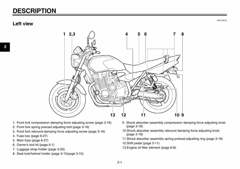
1. Front fork compression damping force adjusting screw (page 3-16)2. Front fork spring preload adjusting bolt (page 3-16)3. Front fork rebound damping force adjusting screw (page 3-16)4. Fuse box (page 6-27)5. Main fuse (page 6-27)6. Owner’s tool kit (page 6-1)7. Luggage strap holder (page 3-20)8. Seat lock/helmet holder (page 3-15/page 3-15)
9. Shock absorber assembly compression damping force adjusting knob (page 3-18)
10.Shock absorber assembly rebound damping force adjusting knob (page 3-18)
11.Shock absorber assembly spring preload adjusting ring (page 3-18)12.Shift pedal (page 3-11)13.Engine oil filter element (page 6-8)
U5WME5E0.book Page 1 Wednesday, December 5, 2007 10:30 AM
DESCRIPTION
2-2
2
EAU10420
Right view
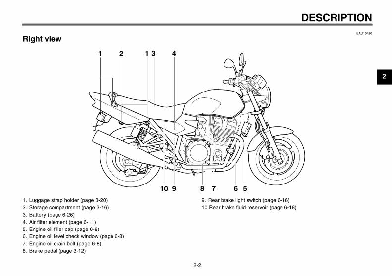
1. Luggage strap holder (page 3-20)2. Storage compartment (page 3-16)3. Battery (page 6-26)4. Air filter element (page 6-11)5. Engine oil filler cap (page 6-8)6. Engine oil level check window (page 6-8)7. Engine oil drain bolt (page 6-8)8. Brake pedal (page 3-12)
9. Rear brake light switch (page 6-16)10.Rear brake fluid reservoir (page 6-18)
U5WME5E0.book Page 2 Wednesday, December 5, 2007 10:30 AM
DESCRIPTION
2-3
2
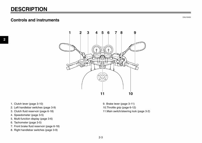
EAU10430
Controls and instruments
1. Clutch lever (page 3-10)2. Left handlebar switches (page 3-9)3. Clutch fluid reservoir (page 6-18)4. Speedometer (page 3-5)5. Multi-function display (page 3-6)6. Tachometer (page 3-5)7. Front brake fluid reservoir (page 6-18)8. Right handlebar switches (page 3-9)
9. Brake lever (page 3-11)10.Throttle grip (page 6-12)11.Main switch/steering lock (page 3-2)
U5WME5E0.book Page 3 Wednesday, December 5, 2007 10:30 AM
INSTRUMENT AND CONTROL FUNCTIONS
3-1
3
EAU10974
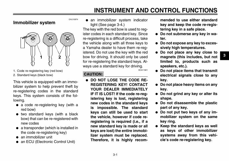
Immobilizer system
This vehicle is equipped with an immo-bilizer system to help prevent theft byre-registering codes in the standardkeys. This system consists of the fol-lowing.
� a code re-registering key (with ared bow)
� two standard keys (with a blackbow) that can be re-registered withnew codes
� a transponder (which is installed inthe code re-registering key)
� an immobilizer unit� an ECU (Electronic Control Unit)
� an immobilizer system indicatorlight (See page 3-4.)
The key with the red bow is used to reg-ister codes in each standard key. Sincere-registering is a difficult process, takethe vehicle along with all three keys toa Yamaha dealer to have them re-reg-istered. Do not use the key with the redbow for driving. It should only be usedfor re-registering the standard keys. Al-ways use a standard key for driving.
CAUTION:ECA11821
� DO NOT LOSE THE CODE RE-REGISTERING KEY! CONTACTYOUR DEALER IMMEDIATELYIF IT IS LOST! If the code re-reg-istering key is lost, registeringnew codes in the standard keysis impossible. The standardkeys can still be used to startthe vehicle, however if code re-registering is required (i.e., if anew standard key is made or allkeys are lost) the entire immobi-lizer system must be replaced.Therefore, it is highly recom-
mended to use either standardkey and keep the code re-regis-tering key in a safe place.
� Do not submerse any key in wa-ter.
� Do not expose any key to exces-sively high temperatures.
� Do not place any key close tomagnets (this includes, but notlimited to, products such asspeakers, etc.).
� Do not place items that transmitelectrical signals close to anykey.
� Do not place heavy items on anykey.
� Do not grind any key or alter itsshape.
� Do not disassemble the plasticpart of any key.
� Do not put two keys of any im-mobilizer system on the samekey ring.
� Keep the standard keys as wellas keys of other immobilizersystems away from this vehi-cle’s code re-registering key.
1. Code re-registering key (red bow)2. Standard keys (black bow)
U5WME5E0.book Page 1 Wednesday, December 5, 2007 10:30 AM
INSTRUMENT AND CONTROL FUNCTIONS
3-2
3
� Keep other immobilizer systemkeys away from the main switchas they may cause signal inter-ference.
EAU10471
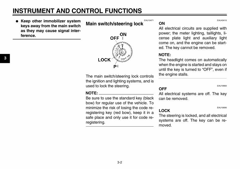
Main switch/steering lock
The main switch/steering lock controlsthe ignition and lighting systems, and isused to lock the steering.
NOTE:Be sure to use the standard key (blackbow) for regular use of the vehicle. Tominimize the risk of losing the code re-registering key (red bow), keep it in asafe place and only use it for code re-registering.
EAU43410
ONAll electrical circuits are supplied withpower; the meter lighting, taillights, li-cense plate light and auxiliary lightcome on, and the engine can be start-ed. The key cannot be removed.
NOTE:The headlight comes on automaticallywhen the engine is started and stays onuntil the key is turned to “OFF”, even ifthe engine stalls.
EAU10660
OFFAll electrical systems are off. The keycan be removed.
EAU10690
LOCKThe steering is locked, and all electricalsystems are off. The key can be re-moved.
U5WME5E0.book Page 2 Wednesday, December 5, 2007 10:30 AM
INSTRUMENT AND CONTROL FUNCTIONS
3-3
3
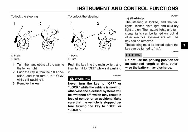
To lock the steering
1. Turn the handlebars all the way tothe left or right.
2. Push the key in from the “OFF” po-sition, and then turn it to “LOCK”while still pushing it.
3. Remove the key.
To unlock the steering
Push the key into the main switch, andthen turn it to “OFF” while still pushingit.
WARNINGEWA10060
Never turn the key to “OFF” or“LOCK” while the vehicle is moving,otherwise the electrical systems willbe switched off, which may result inloss of control or an accident. Makesure that the vehicle is stopped be-fore turning the key to “OFF” or“LOCK”.
EAU43460
(Parking)The steering is locked, and the tail-lights, license plate light and auxiliarylight are on. The hazard lights and turnsignal lights can be turned on, but allother electrical systems are off. Thekey can be removed.The steering must be locked before thekey can be turned to “ ”.
CAUTION:ECA11020
Do not use the parking position foran extended length of time, other-wise the battery may discharge.
1. Push.2. Turn.
1. Push.2. Turn.
U5WME5E0.book Page 3 Wednesday, December 5, 2007 10:30 AM
INSTRUMENT AND CONTROL FUNCTIONS
3-4
3
EAU11003
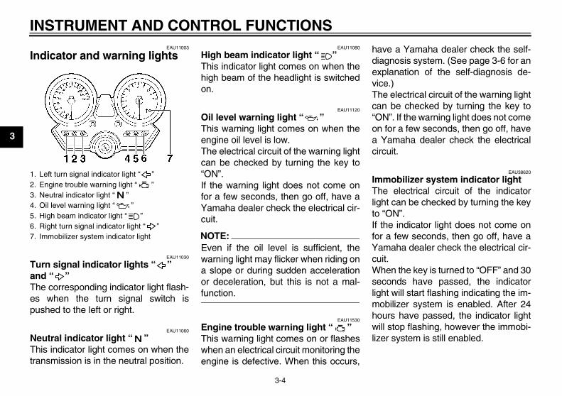
Indicator and warning lights
EAU11030
Turn signal indicator lights “ ” and “ ” The corresponding indicator light flash-es when the turn signal switch ispushed to the left or right.
EAU11060
Neutral indicator light “ ” This indicator light comes on when thetransmission is in the neutral position.
EAU11080
High beam indicator light “ ” This indicator light comes on when thehigh beam of the headlight is switchedon.
EAU11120
Oil level warning light “ ” This warning light comes on when theengine oil level is low.The electrical circuit of the warning lightcan be checked by turning the key to“ON”.If the warning light does not come onfor a few seconds, then go off, have aYamaha dealer check the electrical cir-cuit.
NOTE:Even if the oil level is sufficient, thewarning light may flicker when riding ona slope or during sudden accelerationor deceleration, but this is not a mal-function.
EAU11530
Engine trouble warning light “ ” This warning light comes on or flasheswhen an electrical circuit monitoring theengine is defective. When this occurs,
have a Yamaha dealer check the self-diagnosis system. (See page 3-6 for anexplanation of the self-diagnosis de-vice.)The electrical circuit of the warning lightcan be checked by turning the key to“ON”. If the warning light does not comeon for a few seconds, then go off, havea Yamaha dealer check the electricalcircuit.
EAU38620
Immobilizer system indicator light The electrical circuit of the indicatorlight can be checked by turning the keyto “ON”.If the indicator light does not come onfor a few seconds, then go off, have aYamaha dealer check the electrical cir-cuit.When the key is turned to “OFF” and 30seconds have passed, the indicatorlight will start flashing indicating the im-mobilizer system is enabled. After 24hours have passed, the indicator lightwill stop flashing, however the immobi-lizer system is still enabled.
1. Left turn signal indicator light “ ”2. Engine trouble warning light “ ”3. Neutral indicator light “ ”4. Oil level warning light “ ”5. High beam indicator light “ ”6. Right turn signal indicator light “ ”7. Immobilizer system indicator light
U5WME5E0.book Page 4 Wednesday, December 5, 2007 10:30 AM
INSTRUMENT AND CONTROL FUNCTIONS
3-5
3
This model is also equipped with a self-diagnosis device for the immobilizersystem. (See page 3-6 for an explana-tion of the self-diagnosis device.)
EAU11601
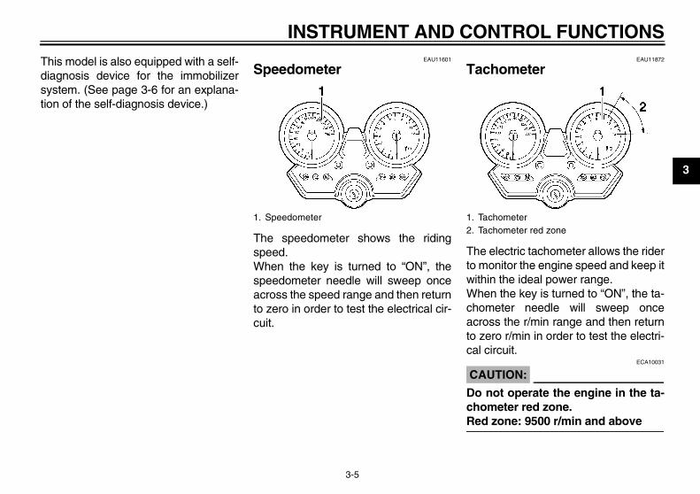
Speedometer
The speedometer shows the ridingspeed.When the key is turned to “ON”, thespeedometer needle will sweep onceacross the speed range and then returnto zero in order to test the electrical cir-cuit.
EAU11872
Tachometer
The electric tachometer allows the riderto monitor the engine speed and keep itwithin the ideal power range.When the key is turned to “ON”, the ta-chometer needle will sweep onceacross the r/min range and then returnto zero r/min in order to test the electri-cal circuit.
CAUTION:ECA10031
Do not operate the engine in the ta-chometer red zone.Red zone: 9500 r/min and above
1. Speedometer 1. Tachometer2. Tachometer red zone
U5WME5E0.book Page 5 Wednesday, December 5, 2007 10:30 AM
INSTRUMENT AND CONTROL FUNCTIONS
3-6
3
EAU43244
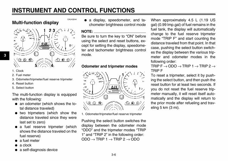
Multi-function display
The multi-function display is equippedwith the following:
� an odometer (which shows the to-tal distance traveled)
� two tripmeters (which show thedistance traveled since they werelast set to zero)
� a fuel reserve tripmeter (whichshows the distance traveled on thefuel reserve)
� a fuel meter� a clock� a self-diagnosis device
� a display, speedometer, and ta-chometer brightness control mode
NOTE:Be sure to turn the key to “ON” beforeusing the select and reset buttons, ex-cept for setting the display, speedome-ter and tachometer brightness controlmode.
Odometer and tripmeter modes
Pushing the select button switches thedisplay between the odometer mode“ODO” and the tripmeter modes “TRIP1” and “TRIP 2” in the following order:ODO → TRIP 1 → TRIP 2 → ODO
When approximately 4.5 L (1.19 USgal) (0.99 Imp.gal) of fuel remains in thefuel tank, the display will automaticallychange to the fuel reserve tripmetermode “TRIP F” and start counting thedistance traveled from that point. In thatcase, pushing the select button switch-es the display between the various trip-meter and odometer modes in thefollowing order:TRIP F → ODO → TRIP 1 → TRIP 2 →TRIP FTo reset a tripmeter, select it by push-ing the select button, and then push thereset button for at least two seconds. Ifyou do not reset the fuel reserve trip-meter manually, it will reset itself auto-matically and the display will return tothe prior mode after refueling and trav-eling 5 km (3 mi).
1. Clock2. Fuel meter3. Odometer/tripmeter/fuel reserve tripmeter4. Reset button5. Select button
1. Odometer/tripmeter/fuel reserve tripmeter
U5WME5E0.book Page 6 Wednesday, December 5, 2007 10:30 AM
INSTRUMENT AND CONTROL FUNCTIONS
3-7
3
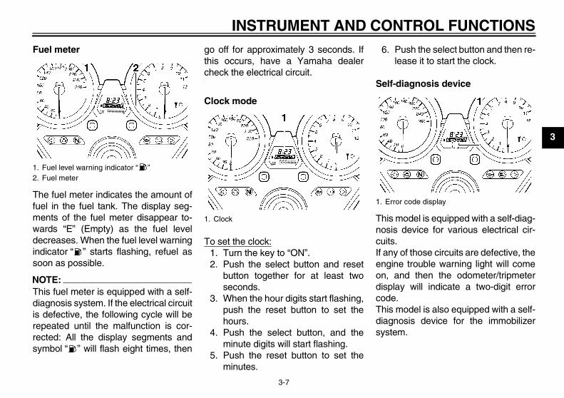
Fuel meter
The fuel meter indicates the amount offuel in the fuel tank. The display seg-ments of the fuel meter disappear to-wards “E” (Empty) as the fuel leveldecreases. When the fuel level warningindicator “ ” starts flashing, refuel assoon as possible.
NOTE:This fuel meter is equipped with a self-diagnosis system. If the electrical circuitis defective, the following cycle will berepeated until the malfunction is cor-rected: All the display segments andsymbol “ ” will flash eight times, then
go off for approximately 3 seconds. Ifthis occurs, have a Yamaha dealercheck the electrical circuit.
Clock mode
To set the clock:1. Turn the key to “ON”.2. Push the select button and reset
button together for at least twoseconds.
3. When the hour digits start flashing,push the reset button to set thehours.
4. Push the select button, and theminute digits will start flashing.
5. Push the reset button to set theminutes.
6. Push the select button and then re-lease it to start the clock.
Self-diagnosis device
This model is equipped with a self-diag-nosis device for various electrical cir-cuits.If any of those circuits are defective, theengine trouble warning light will comeon, and then the odometer/tripmeterdisplay will indicate a two-digit errorcode.This model is also equipped with a self-diagnosis device for the immobilizersystem.
1. Fuel level warning indicator “ ”2. Fuel meter
1. Clock
1. Error code display
U5WME5E0.book Page 7 Wednesday, December 5, 2007 10:30 AM
INSTRUMENT AND CONTROL FUNCTIONS
3-8
3
If any of the immobilizer system circuitsare defective, the immobilizer systemindicator light will flash, and then thedisplay will indicate a two-digit errorcode.
NOTE:If the display indicates error code 52,this could be caused by transponder in-terference. If this error code appears,try the following.
1. Use the code re-registering key tostart the engine.
NOTE:Make sure there are no other immobi-lizer keys close to the main switch, anddo not keep more than one immobilizerkey on the same key ring! Immobilizersystem keys may cause signal interfer-ence, which may prevent the enginefrom starting.
2. If the engine starts, turn it off andtry starting the engine with thestandard keys.
3. If one or both of the standard keysdo not start the engine, take thevehicle, the code re-registering
key and both standard keys to aYamaha dealer and have the stan-dard keys re-registered.
If the display indicates any error codes,note the code number, and then have aYamaha dealer check the vehicle.
CAUTION:ECA11790
If the multi-function display indi-cates an error code, the vehicleshould be checked as soon as pos-sible in order to avoid engine dam-age.
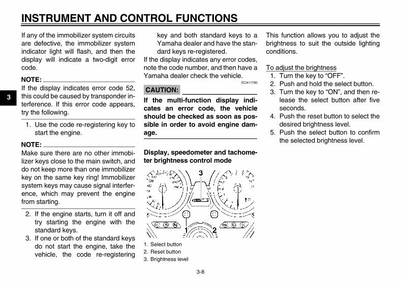
Display, speedometer and tachome-ter brightness control mode
This function allows you to adjust thebrightness to suit the outside lightingconditions.
To adjust the brightness1. Turn the key to “OFF”.2. Push and hold the select button.3. Turn the key to “ON”, and then re-
lease the select button after fiveseconds.
4. Push the reset button to select thedesired brightness level.
5. Push the select button to confirmthe selected brightness level.
1. Select button2. Reset button3. Brightness level
U5WME5E0.book Page 8 Wednesday, December 5, 2007 10:30 AM
INSTRUMENT AND CONTROL FUNCTIONS
3-9
3
EAU12331
Anti-theft alarm (optional) This model can be equipped with anoptional anti-theft alarm by a Yamahadealer. Contact a Yamaha dealer formore information.
EAU12347
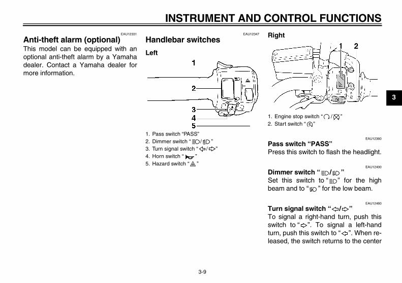
Handlebar switches
Left
Right
EAU12360
Pass switch “PASS” Press this switch to flash the headlight.
EAU12400
Dimmer switch “ / ” Set this switch to “ ” for the highbeam and to “ ” for the low beam.
EAU12460
Turn signal switch “ / ” To signal a right-hand turn, push thisswitch to “ ”. To signal a left-handturn, push this switch to “ ”. When re-leased, the switch returns to the center
1. Pass switch “PASS”2. Dimmer switch “ / ”3. Turn signal switch “ / ”4. Horn switch “ ”5. Hazard switch “ ”
1. Engine stop switch “ / ”2. Start switch “ ”
U5WME5E0.book Page 9 Wednesday, December 5, 2007 10:30 AM
INSTRUMENT AND CONTROL FUNCTIONS
3-10
3
position. To cancel the turn signallights, push the switch in after it has re-turned to the center position.
EAU12500
Horn switch “ ” Press this switch to sound the horn.
EAU12660
Engine stop switch “ / ” Set this switch to “ ” before startingthe engine. Set this switch to “ ” tostop the engine in case of an emergen-cy, such as when the vehicle overturnsor when the throttle cable is stuck.
EAU12710
Start switch “ ” Push this switch to crank the enginewith the starter.
CAUTION:ECA10050
See page 5-1 for starting instruc-tions prior to starting the engine.
EAU41700
The engine trouble warning light willcome on when the key is turned to “ON”and the start switch is pushed, but thisdoes not indicate a malfunction.
EAU12733
Hazard switch “ ” With the key in the “ON” or “ ” posi-tion, use this switch to turn on the haz-ard lights (simultaneous flashing of allturn signal lights).The hazard lights are used in case ofan emergency or to warn other driverswhen your vehicle is stopped where itmight be a traffic hazard.
CAUTION:ECA10061
Do not use the hazard lights for anextended length of time with the en-gine not running, otherwise the bat-tery may discharge.
EAU12830
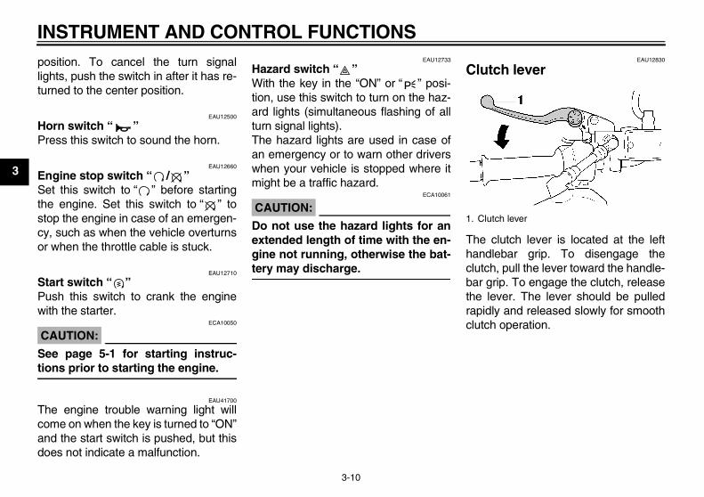
Clutch lever
The clutch lever is located at the lefthandlebar grip. To disengage theclutch, pull the lever toward the handle-bar grip. To engage the clutch, releasethe lever. The lever should be pulledrapidly and released slowly for smoothclutch operation.
1. Clutch lever
U5WME5E0.book Page 10 Wednesday, December 5, 2007 10:30 AM
INSTRUMENT AND CONTROL FUNCTIONS
3-11
3
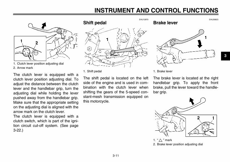
The clutch lever is equipped with aclutch lever position adjusting dial. Toadjust the distance between the clutchlever and the handlebar grip, turn theadjusting dial while holding the leverpushed away from the handlebar grip.Make sure that the appropriate settingon the adjusting dial is aligned with thearrow mark on the clutch lever.The clutch lever is equipped with aclutch switch, which is part of the igni-tion circuit cut-off system. (See page3-22.)
EAU12870
Shift pedal
The shift pedal is located on the leftside of the engine and is used in com-bination with the clutch lever whenshifting the gears of the 5-speed con-stant-mesh transmission equipped onthis motorcycle.
EAU26823
Brake lever
The brake lever is located at the righthandlebar grip. To apply the frontbrake, pull the lever toward the handle-bar grip.
1. Clutch lever position adjusting dial2. Arrow mark
1. Shift pedal 1. Brake lever
1. “ ” mark2. Brake lever position adjusting dial
U5WME5E0.book Page 11 Wednesday, December 5, 2007 10:30 AM
INSTRUMENT AND CONTROL FUNCTIONS
3-12
3
The brake lever is equipped with abrake lever position adjusting dial. Toadjust the distance between the brakelever and the handlebar grip, turn theadjusting dial while holding the leverpushed away from the handlebar grip.Make sure that the appropriate settingon the adjusting dial is aligned withthe “ ” mark on the brake lever.
EAU12941
Brake pedal
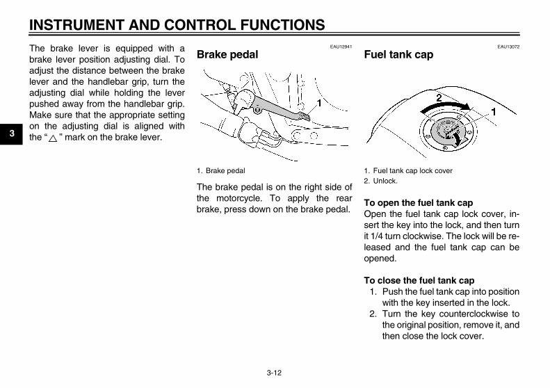
The brake pedal is on the right side ofthe motorcycle. To apply the rearbrake, press down on the brake pedal.
EAU13072
Fuel tank cap
To open the fuel tank capOpen the fuel tank cap lock cover, in-sert the key into the lock, and then turnit 1/4 turn clockwise. The lock will be re-leased and the fuel tank cap can beopened.
To close the fuel tank cap1. Push the fuel tank cap into position
with the key inserted in the lock.2. Turn the key counterclockwise to
the original position, remove it, andthen close the lock cover.
1. Brake pedal 1. Fuel tank cap lock cover2. Unlock.
U5WME5E0.book Page 12 Wednesday, December 5, 2007 10:30 AM
INSTRUMENT AND CONTROL FUNCTIONS
3-13
3
NOTE:The fuel tank cap cannot be closed un-less the key is in the lock. In addition,the key cannot be removed if the cap isnot properly closed and locked.
WARNINGEWA11090
Make sure that the fuel tank cap isproperly closed before riding.
EAU13220
Fuel
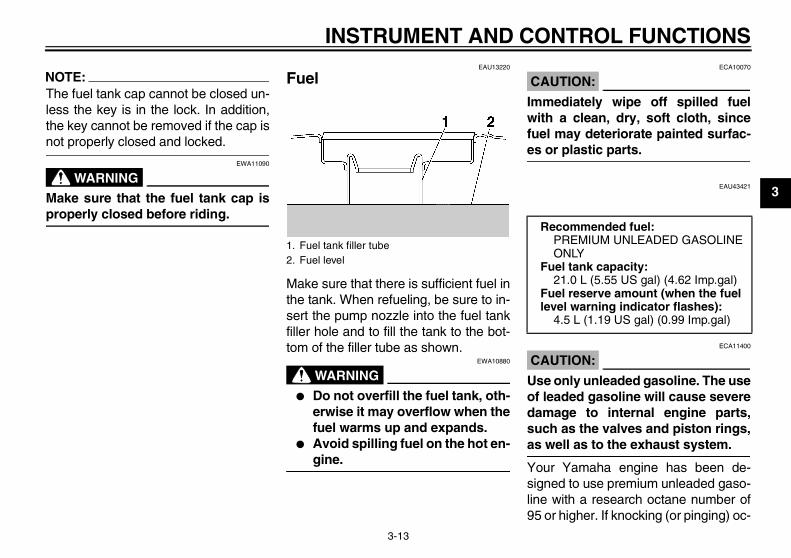
Make sure that there is sufficient fuel inthe tank. When refueling, be sure to in-sert the pump nozzle into the fuel tankfiller hole and to fill the tank to the bot-tom of the filler tube as shown.
WARNINGEWA10880
� Do not overfill the fuel tank, oth-erwise it may overflow when thefuel warms up and expands.
� Avoid spilling fuel on the hot en-gine.
CAUTION:ECA10070
Immediately wipe off spilled fuelwith a clean, dry, soft cloth, sincefuel may deteriorate painted surfac-es or plastic parts.
EAU43421
CAUTION:ECA11400
Use only unleaded gasoline. The useof leaded gasoline will cause severedamage to internal engine parts,such as the valves and piston rings,as well as to the exhaust system.
Your Yamaha engine has been de-signed to use premium unleaded gaso-line with a research octane number of95 or higher. If knocking (or pinging) oc-
1. Fuel tank filler tube2. Fuel level
Recommended fuel:PREMIUM UNLEADED GASOLINE ONLY
Fuel tank capacity:21.0 L (5.55 US gal) (4.62 Imp.gal)
Fuel reserve amount (when the fuel level warning indicator flashes):
4.5 L (1.19 US gal) (0.99 Imp.gal)
U5WME5E0.book Page 13 Wednesday, December 5, 2007 10:30 AM
INSTRUMENT AND CONTROL FUNCTIONS
3-14
3
curs, use a gasoline of a differentbrand. Use of unleaded fuel will extendspark plug life and reduce maintenancecosts.
EAU13412
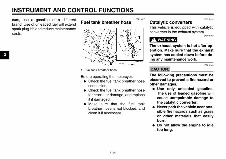
Fuel tank breather hose
Before operating the motorcycle:� Check the fuel tank breather hose
connection.� Check the fuel tank breather hose
for cracks or damage, and replaceit if damaged.
� Make sure that the fuel tankbreather hose is not blocked, andclean it if necessary.
EAU13442
Catalytic converters This vehicle is equipped with catalyticconverters in the exhaust system.
WARNINGEWA10860
The exhaust system is hot after op-eration. Make sure that the exhaustsystem has cooled down before do-ing any maintenance work.
CAUTION:ECA10700
The following precautions must beobserved to prevent a fire hazard orother damages.
� Use only unleaded gasoline.The use of leaded gasoline willcause unrepairable damage tothe catalytic converter.
� Never park the vehicle near pos-sible fire hazards such as grassor other materials that easilyburn.
� Do not allow the engine to idletoo long.
1. Fuel tank breather hose
U5WME5E0.book Page 14 Wednesday, December 5, 2007 10:30 AM
INSTRUMENT AND CONTROL FUNCTIONS
3-15
3
EAU13900
Seat
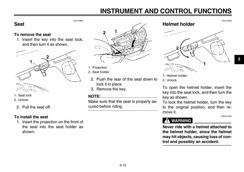
To remove the seat1. Insert the key into the seat lock,
and then turn it as shown.
2. Pull the seat off.
To install the seat1. Insert the projection on the front of
the seat into the seat holder asshown.
2. Push the rear of the seat down tolock it in place.
3. Remove the key.
NOTE:Make sure that the seat is properly se-cured before riding.
EAU14350
Helmet holder
To open the helmet holder, insert thekey into the seat lock, and then turn thekey as shown.To lock the helmet holder, turn the keyto the original position, and then re-move it.
WARNINGEWA10160
Never ride with a helmet attached tothe helmet holder, since the helmetmay hit objects, causing loss of con-trol and possibly an accident.
1. Seat lock2. Unlock.
1. Projection2. Seat holder
1. Helmet holder2. Unlock.
U5WME5E0.book Page 15 Wednesday, December 5, 2007 10:30 AM
INSTRUMENT AND CONTROL FUNCTIONS
3-16
3
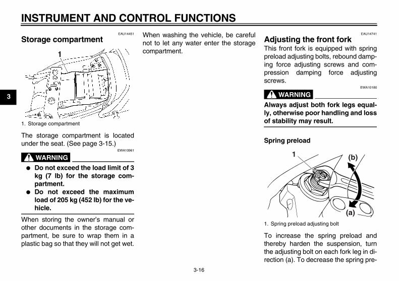
EAU14451
Storage compartment
The storage compartment is locatedunder the seat. (See page 3-15.)
WARNINGEWA10961
� Do not exceed the load limit of 3kg (7 lb) for the storage com-partment.
� Do not exceed the maximumload of 205 kg (452 lb) for the ve-hicle.
When storing the owner’s manual orother documents in the storage com-partment, be sure to wrap them in aplastic bag so that they will not get wet.
When washing the vehicle, be carefulnot to let any water enter the storagecompartment.
EAU14741
Adjusting the front fork This front fork is equipped with springpreload adjusting bolts, rebound damp-ing force adjusting screws and com-pression damping force adjustingscrews.
WARNINGEWA10180
Always adjust both fork legs equal-ly, otherwise poor handling and lossof stability may result.
Spring preload
To increase the spring preload andthereby harden the suspension, turnthe adjusting bolt on each fork leg in di-rection (a). To decrease the spring pre-
1. Storage compartment
1. Spring preload adjusting bolt
1
(a)
(b)
U5WME5E0.book Page 16 Wednesday, December 5, 2007 10:30 AM
INSTRUMENT AND CONTROL FUNCTIONS
3-17
3
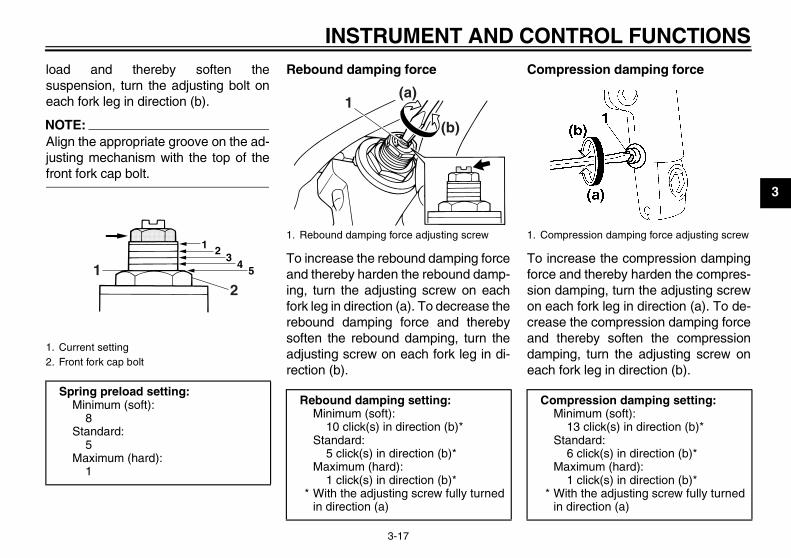
load and thereby soften thesuspension, turn the adjusting bolt oneach fork leg in direction (b).
NOTE:Align the appropriate groove on the ad-justing mechanism with the top of thefront fork cap bolt.
Rebound damping force
To increase the rebound damping forceand thereby harden the rebound damp-ing, turn the adjusting screw on eachfork leg in direction (a). To decrease therebound damping force and therebysoften the rebound damping, turn theadjusting screw on each fork leg in di-rection (b).
Compression damping force
To increase the compression dampingforce and thereby harden the compres-sion damping, turn the adjusting screwon each fork leg in direction (a). To de-crease the compression damping forceand thereby soften the compressiondamping, turn the adjusting screw oneach fork leg in direction (b).
1. Current setting2. Front fork cap bolt
Spring preload setting:Minimum (soft):
8Standard:
5Maximum (hard):
1
1 23
45
21
1. Rebound damping force adjusting screw
Rebound damping setting:Minimum (soft):
10 click(s) in direction (b)*Standard:
5 click(s) in direction (b)*Maximum (hard):
1 click(s) in direction (b)** With the adjusting screw fully turned
in direction (a)
1(a)
(b)
1. Compression damping force adjusting screw
Compression damping setting:Minimum (soft):
13 click(s) in direction (b)*Standard:
6 click(s) in direction (b)*Maximum (hard):
1 click(s) in direction (b)** With the adjusting screw fully turned
in direction (a)
U5WME5E0.book Page 17 Wednesday, December 5, 2007 10:30 AM
INSTRUMENT AND CONTROL FUNCTIONS
3-18
3
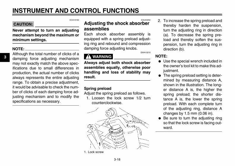
CAUTION:ECA10100
Never attempt to turn an adjustingmechanism beyond the maximum orminimum settings.
NOTE:Although the total number of clicks of adamping force adjusting mechanismmay not exactly match the above spec-ifications due to small differences inproduction, the actual number of clicksalways represents the entire adjustingrange. To obtain a precise adjustment,it would be advisable to check the num-ber of clicks of each damping force ad-justing mechanism and to modify thespecifications as necessary.
EAU43252
Adjusting the shock absorber assemblies Each shock absorber assembly isequipped with a spring preload adjust-ing ring and rebound and compressiondamping force adjusting knobs.
WARNINGEWA10210
Always adjust both shock absorberassemblies equally, otherwise poorhandling and loss of stability mayresult.
Spring preloadAdjust the spring preload as follows.
1. Loosen the lock screw 1/2 turncounterclockwise.
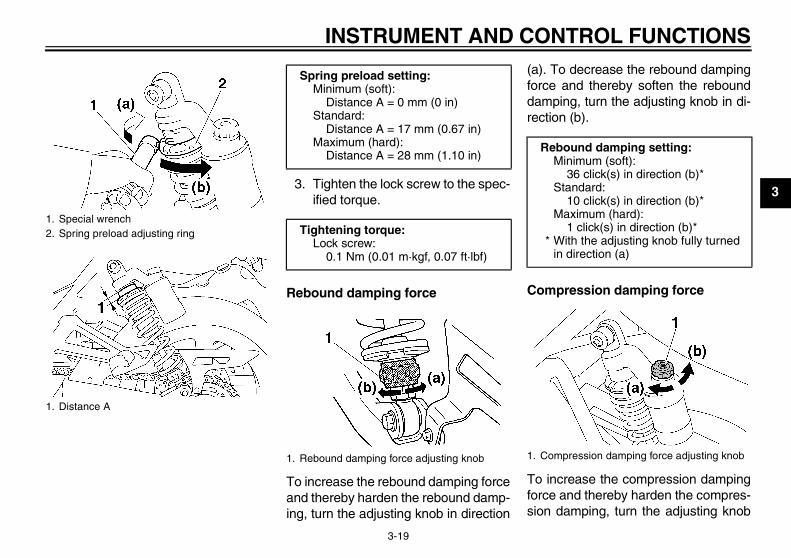
2. To increase the spring preload andthereby harden the suspension,turn the adjusting ring in direction(a). To decrease the spring pre-load and thereby soften the sus-pension, turn the adjusting ring indirection (b).
NOTE:� Use the special wrench included in
the owner’s tool kit to make this ad-justment.
� The spring preload setting is deter-mined by measuring distance A,shown in the illustration. The long-er distance A is, the higher thespring preload; the shorter dis-tance A is, the lower the springpreload. With each complete turnof the adjusting ring, distance Achanges by 1.5 mm (0.06 in).
� Be sure to turn the adjusting ringso that the lock screw is facing out-ward.
1. Lock screw
U5WME5E0.book Page 18 Wednesday, December 5, 2007 10:30 AM
INSTRUMENT AND CONTROL FUNCTIONS
3-19
33. Tighten the lock screw to the spec-ified torque.
Rebound damping force
To increase the rebound damping forceand thereby harden the rebound damp-ing, turn the adjusting knob in direction
(a). To decrease the rebound dampingforce and thereby soften the rebounddamping, turn the adjusting knob in di-rection (b).
Compression damping force
To increase the compression dampingforce and thereby harden the compres-sion damping, turn the adjusting knob
1. Special wrench2. Spring preload adjusting ring
1. Distance A
Spring preload setting:Minimum (soft):
Distance A = 0 mm (0 in)Standard:
Distance A = 17 mm (0.67 in)Maximum (hard):
Distance A = 28 mm (1.10 in)
Tightening torque:Lock screw:
0.1 Nm (0.01 m·kgf, 0.07 ft·lbf)
1. Rebound damping force adjusting knob
Rebound damping setting:Minimum (soft):
36 click(s) in direction (b)*Standard:
10 click(s) in direction (b)*Maximum (hard):
1 click(s) in direction (b)** With the adjusting knob fully turned
in direction (a)
1. Compression damping force adjusting knob
U5WME5E0.book Page 19 Wednesday, December 5, 2007 10:30 AM
INSTRUMENT AND CONTROL FUNCTIONS
3-20
3
in direction (a). To decrease the com-pression damping force and therebysoften the compression damping, turnthe adjusting knob in direction (b).
CAUTION:ECA10100
Never attempt to turn an adjustingmechanism beyond the maximum orminimum settings.
NOTE:Although the total number of clicks of adamping force adjusting mechanismmay not exactly match the above spec-ifications due to small differences inproduction, the actual number of clicksalways represents the entire adjustingrange. To obtain a precise adjustment,it would be advisable to check the num-
ber of clicks of each damping force ad-justing mechanism and to modify thespecifications as necessary.
WARNINGEWA10230
These shock absorbers containhighly pressurized nitrogen gas. Forproper handling read and under-stand the following information be-fore handling the shock absorbers.The manufacturer cannot be held re-sponsible for property damage orpersonal injury that may result fromimproper handling.
� Do not tamper with or attempt toopen the gas cylinders.
� Do not subject the shock ab-sorbers to an open flame or oth-er high heat sources, otherwisethey may explode due to exces-sive gas pressure.
� Do not deform or damage thegas cylinders in any way, as thiswill result in poor damping per-formance.
� Always have a Yamaha dealerservice the shock absorbers.
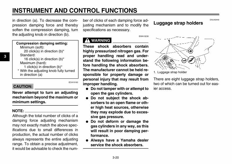
EAU43440
Luggage strap holders
There are eight luggage strap holders,two of which can be turned out for eas-ier access.
Compression damping setting:Minimum (soft):
20 click(s) in direction (b)*Standard:
16 click(s) in direction (b)*Maximum (hard):
1 click(s) in direction (b)** With the adjusting knob fully turned
in direction (a)1. Luggage strap holder
U5WME5E0.book Page 20 Wednesday, December 5, 2007 10:30 AM
INSTRUMENT AND CONTROL FUNCTIONS
3-21
3
EAU15281
EXUP system This model is equipped with Yamaha’sEXUP (EXhaust Ultimate Power valve)system. This system boosts enginepower by means of a valve that regu-lates the diameter of the exhaust pipe.The EXUP system valve is constantlyadjusted in accordance with the enginespeed by a computer-controlled servo-motor.
CAUTION:ECA10191
� The EXUP system has been setand extensively tested at theYamaha factory. Changingthese settings without sufficienttechnical knowledge may resultin poor performance of or dam-age to the engine.
� If the EXUP system cannot beheard when the main switch isturned on, have a Yamaha deal-er check it.
EAU15301
Sidestand The sidestand is located on the left sideof the frame. Raise the sidestand orlower it with your foot while holding thevehicle upright.
NOTE:The built-in sidestand switch is part ofthe ignition circuit cut-off system, whichcuts the ignition in certain situations.(See further down for an explanation ofthe ignition circuit cut-off system.)
WARNINGEWA10240
The vehicle must not be ridden withthe sidestand down, or if the side-stand cannot be properly moved up(or does not stay up), otherwise thesidestand could contact the groundand distract the operator, resultingin a possible loss of control.Yamaha’s ignition circuit cut-offsystem has been designed to assistthe operator in fulfilling the respon-sibility of raising the sidestand be-fore starting off. Therefore, checkthis system regularly as described
below and have a Yamaha dealer re-pair it if it does not function proper-ly.
U5WME5E0.book Page 21 Wednesday, December 5, 2007 10:30 AM
INSTRUMENT AND CONTROL FUNCTIONS
3-22
3
EAU44900
Ignition circuit cut-off system The ignition circuit cut-off system (com-prising the sidestand switch, clutchswitch and neutral switch) has the fol-lowing functions.
� It prevents starting when the trans-mission is in gear and the side-stand is up, but the clutch lever isnot pulled.
� It prevents starting when the trans-mission is in gear and the clutch le-ver is pulled, but the sidestand isstill down.
� It cuts the running engine when thetransmission is in gear and the sid-estand is moved down.
Periodically check the operation of theignition circuit cut-off system accordingto the following procedure.
WARNINGEWA10260
� The vehicle must be placed onthe centerstand during this in-spection.
� If a malfunction is noted, have aYamaha dealer check the sys-tem before riding.
U5WME5E0.book Page 22 Wednesday, December 5, 2007 10:30 AM
INSTRUMENT AND CONTROL FUNCTIONS
3-23
3
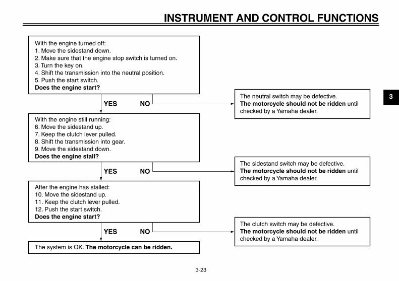
With the engine turned off:1. Move the sidestand down.2. Make sure that the engine stop switch is turned on.3. Turn the key on. 4. Shift the transmission into the neutral position.5. Push the start switch.Does the engine start?
With the engine still running:6. Move the sidestand up.7. Keep the clutch lever pulled.8. Shift the transmission into gear.9. Move the sidestand down.Does the engine stall?
After the engine has stalled:10. Move the sidestand up.11. Keep the clutch lever pulled.12. Push the start switch.Does the engine start?
The system is OK. The motorcycle can be ridden.
The neutral switch may be defective.The motorcycle should not be ridden untilchecked by a Yamaha dealer.
The sidestand switch may be defective.The motorcycle should not be ridden untilchecked by a Yamaha dealer.
The clutch switch may be defective.The motorcycle should not be ridden untilchecked by a Yamaha dealer.
YES NO
YES NO
YES NO
U5WME5E0.book Page 23 Wednesday, December 5, 2007 10:30 AM
PRE-OPERATION CHECKS
4-1
4
EAU15593
The condition of a vehicle is the owner’s responsibility. Vital components can start to deteriorate quickly and unexpectedly,even if the vehicle remains unused (for example, as a result of exposure to the elements). Any damage, fluid leakage or lossof tire air pressure could have serious consequences. Therefore, it is very important, in addition to a thorough visual inspec-tion, to check the following points before each ride.
NOTE:Pre-operation checks should be made each time the vehicle is used. Such an inspection can be accomplished in a very shorttime; and the added safety it assures is more than worth the time involved.
WARNINGEWA11150
If any item in the Pre-operation check list is not working properly, have it inspected and repaired before operatingthe vehicle.
U5WME5E0.book Page 1 Wednesday, December 5, 2007 10:30 AM
PRE-OPERATION CHECKS
4-2
4
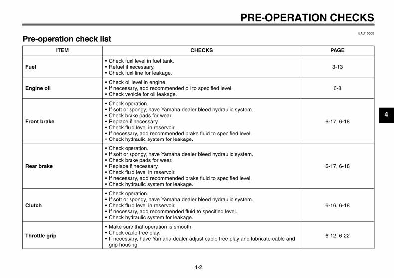
EAU15605
Pre-operation check list ITEM CHECKS PAGE
Fuel• Check fuel level in fuel tank.• Refuel if necessary.• Check fuel line for leakage.
3-13
Engine oil• Check oil level in engine.• If necessary, add recommended oil to specified level.• Check vehicle for oil leakage.
6-8
Front brake
• Check operation.• If soft or spongy, have Yamaha dealer bleed hydraulic system.• Check brake pads for wear.• Replace if necessary.• Check fluid level in reservoir.• If necessary, add recommended brake fluid to specified level.• Check hydraulic system for leakage.
6-17, 6-18
Rear brake
• Check operation.• If soft or spongy, have Yamaha dealer bleed hydraulic system.• Check brake pads for wear.• Replace if necessary.• Check fluid level in reservoir.• If necessary, add recommended brake fluid to specified level.• Check hydraulic system for leakage.
6-17, 6-18
Clutch
• Check operation.• If soft or spongy, have Yamaha dealer bleed hydraulic system.• Check fluid level in reservoir.• If necessary, add recommended fluid to specified level.• Check hydraulic system for leakage.
6-16, 6-18
Throttle grip
• Make sure that operation is smooth.• Check cable free play.• If necessary, have Yamaha dealer adjust cable free play and lubricate cable and
grip housing.
6-12, 6-22
U5WME5E0.book Page 2 Wednesday, December 5, 2007 10:30 AM
PRE-OPERATION CHECKS
4-3
4
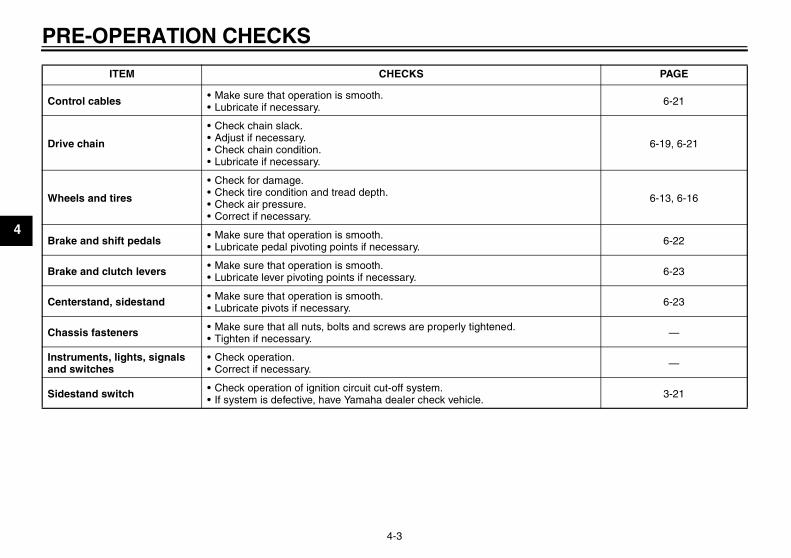
Control cables • Make sure that operation is smooth.• Lubricate if necessary. 6-21
Drive chain
• Check chain slack.• Adjust if necessary.• Check chain condition.• Lubricate if necessary.
6-19, 6-21
Wheels and tires
• Check for damage.• Check tire condition and tread depth.• Check air pressure.• Correct if necessary.
6-13, 6-16
Brake and shift pedals • Make sure that operation is smooth.• Lubricate pedal pivoting points if necessary. 6-22
Brake and clutch levers • Make sure that operation is smooth.• Lubricate lever pivoting points if necessary. 6-23
Centerstand, sidestand • Make sure that operation is smooth.• Lubricate pivots if necessary. 6-23
Chassis fasteners • Make sure that all nuts, bolts and screws are properly tightened.• Tighten if necessary. —
Instruments, lights, signals and switches
• Check operation.• Correct if necessary. —
Sidestand switch • Check operation of ignition circuit cut-off system.• If system is defective, have Yamaha dealer check vehicle. 3-21
ITEM CHECKS PAGE
U5WME5E0.book Page 3 Wednesday, December 5, 2007 10:30 AM
OPERATION AND IMPORTANT RIDING POINTS
5-1
5
EAU15950
WARNINGEWA10270
� Become thoroughly familiarwith all operating controls andtheir functions before riding.Consult a Yamaha dealer re-garding any control or functionthat you do not thoroughly un-derstand.
� Never start the engine or oper-ate it in a closed area for anylength of time. Exhaust fumesare poisonous, and inhalingthem can cause loss of con-sciousness and death within ashort time. Always make surethat there is adequate ventila-tion.
� Before starting out, make surethat the sidestand is up. If thesidestand is not raised com-pletely, it could contact theground and distract the opera-tor, resulting in a possible lossof control.
EAU45310
NOTE:This model is equipped with a lean an-gle sensor to stop the engine in case ofa turnover. To start the engine after aturnover, be sure to turn the mainswitch to “OFF” and then to “ON”. Fail-ing to do so will prevent the engine fromstarting even though the engine willcrank when pushing the start switch.
EAU32952
Starting the engine In order for the ignition circuit cut-offsystem to enable starting, one of thefollowing conditions must be met:
� The transmission is in the neutralposition.
� The transmission is in gear withthe clutch lever pulled and the sid-estand up.
WARNINGEWA10290
� Before starting the engine,check the function of the igni-tion circuit cut-off system ac-cording to the proceduredescribed on page 3-22.
� Never ride with the sidestanddown.
1. Turn the key to “ON” and makesure that the engine stop switch isset to “ ”.
CAUTION:ECA12741
The following warning lights and in-dicator light should come on for afew seconds, then go off.
� Oil level warning light� Engine trouble warning light
U5WME5E0.book Page 1 Wednesday, December 5, 2007 10:30 AM
OPERATION AND IMPORTANT RIDING POINTS
5-2
5
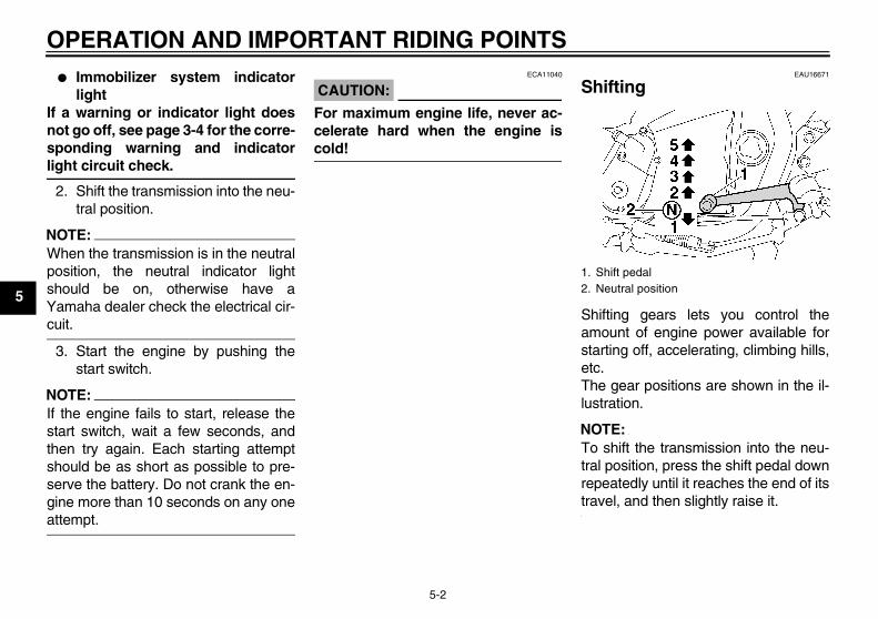
� Immobilizer system indicatorlight
If a warning or indicator light doesnot go off, see page 3-4 for the corre-sponding warning and indicatorlight circuit check.
2. Shift the transmission into the neu-tral position.
NOTE:When the transmission is in the neutralposition, the neutral indicator lightshould be on, otherwise have aYamaha dealer check the electrical cir-cuit.
3. Start the engine by pushing thestart switch.
NOTE:If the engine fails to start, release thestart switch, wait a few seconds, andthen try again. Each starting attemptshould be as short as possible to pre-serve the battery. Do not crank the en-gine more than 10 seconds on any oneattempt.
CAUTION:ECA11040
For maximum engine life, never ac-celerate hard when the engine iscold!
EAU16671
Shifting
Shifting gears lets you control theamount of engine power available forstarting off, accelerating, climbing hills,etc.The gear positions are shown in the il-lustration.
NOTE:To shift the transmission into the neu-tral position, press the shift pedal downrepeatedly until it reaches the end of itstravel, and then slightly raise it.
1. Shift pedal2. Neutral position
U5WME5E0.book Page 2 Wednesday, December 5, 2007 10:30 AM
OPERATION AND IMPORTANT RIDING POINTS
5-3
5
CAUTION:ECA10260
� Even with the transmission inthe neutral position, do notcoast for long periods of timewith the engine off, and do nottow the motorcycle for long dis-tances. The transmission isproperly lubricated only whenthe engine is running. Inade-quate lubrication may damagethe transmission.
� Always use the clutch whilechanging gears to avoid damag-ing the engine, transmission,and drive train, which are notdesigned to withstand theshock of forced shifting.
EAU16810
Tips for reducing fuel con-sumption Fuel consumption depends largely onyour riding style. Consider the followingtips to reduce fuel consumption:
� Shift up swiftly, and avoid high en-gine speeds during acceleration.
� Do not rev the engine while shiftingdown, and avoid high enginespeeds with no load on the engine.
� Turn the engine off instead of let-ting it idle for an extended length oftime (e.g., in traffic jams, at trafficlights or at railroad crossings).
EAU16841
Engine break-in There is never a more important periodin the life of your engine than the periodbetween 0 and 1600 km (1000 mi). Forthis reason, you should read the follow-ing material carefully.Since the engine is brand new, do notput an excessive load on it for the first1600 km (1000 mi). The various parts inthe engine wear and polish themselvesto the correct operating clearances.During this period, prolonged full-throt-tle operation or any condition that mightresult in engine overheating must beavoided.
EAU17091
0–1000 km (0–600 mi)Avoid prolonged operation above 4800r/min.1000–1600 km (600–1000 mi)Avoid prolonged operation above 5700r/min.
U5WME5E0.book Page 3 Wednesday, December 5, 2007 10:30 AM
OPERATION AND IMPORTANT RIDING POINTS
5-4
5
CAUTION:ECA10301
After 1000 km (600 mi) of operation,the engine oil must be changed andthe oil filter cartridge or element re-placed.
1600 km (1000 mi) and beyondThe vehicle can now be operated nor-mally.
CAUTION:ECA10310
� Keep the engine speed out ofthe tachometer red zone.
� If any engine trouble should oc-cur during the engine break-inperiod, immediately have aYamaha dealer check the vehi-cle.
EAU17212
Parking When parking, stop the engine, andthen remove the key from the mainswitch.
WARNINGEWA10310
� Since the engine and exhaustsystem can become very hot,park in a place where pedestri-ans or children are not likely totouch them.
� Do not park on a slope or on softground, otherwise the vehiclemay overturn.
CAUTION:ECA10380
Never park in an area where thereare fire hazards such as grass orother flammable materials.
U5WME5E0.book Page 4 Wednesday, December 5, 2007 10:30 AM
PERIODIC MAINTENANCE AND MINOR REPAIR
6-1
6
EAU17240
Safety is an obligation of the owner. Pe-riodic inspection, adjustment and lubri-cation will keep your vehicle in thesafest and most efficient condition pos-sible. The most important points of in-spection, adjustment, and lubricationare explained on the following pages.The intervals given in the periodicmaintenance and lubrication chartshould be simply considered as a gen-eral guide under normal riding condi-tions. However, DEPENDING ON THEWEATHER, TERRAIN, GEOGRAPHI-CAL LOCATION, AND INDIVIDUALUSE, THE MAINTENANCE INTER-VALS MAY NEED TO BE SHORT-ENED.
WARNINGEWA10320
If you are not familiar with mainte-nance work, have a Yamaha dealerdo it for you.
EAU17380
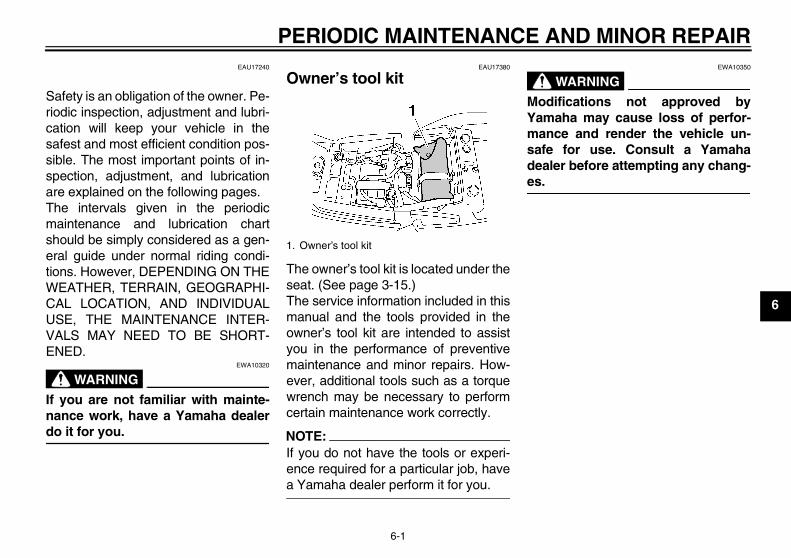
Owner’s tool kit
The owner’s tool kit is located under theseat. (See page 3-15.)The service information included in thismanual and the tools provided in theowner’s tool kit are intended to assistyou in the performance of preventivemaintenance and minor repairs. How-ever, additional tools such as a torquewrench may be necessary to performcertain maintenance work correctly.
NOTE:If you do not have the tools or experi-ence required for a particular job, havea Yamaha dealer perform it for you.
WARNINGEWA10350
Modifications not approved byYamaha may cause loss of perfor-mance and render the vehicle un-safe for use. Consult a Yamahadealer before attempting any chang-es.
1. Owner’s tool kit
U5WME5E0.book Page 1 Wednesday, December 5, 2007 10:30 AM
PERIODIC MAINTENANCE AND MINOR REPAIR
6-2
6
EAU1770A
Periodic maintenance and lubrication chart
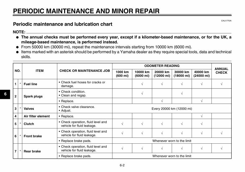
NOTE:� The annual checks must be performed every year, except if a kilometer-based maintenance, or for the UK, a
mileage-based maintenance, is performed instead.� From 50000 km (30000 mi), repeat the maintenance intervals starting from 10000 km (6000 mi).� Items marked with an asterisk should be performed by a Yamaha dealer as they require special tools, data and technical
skills.
NO. ITEM CHECK OR MAINTENANCE JOB
ODOMETER READINGANNUAL CHECK1000 km
(600 mi)10000 km (6000 mi)
20000 km (12000 mi)
30000 km (18000 mi)
40000 km (24000 mi)
1 * Fuel line • Check fuel hoses for cracks or damage. √ √ √ √ √
2 Spark plugs• Check condition.• Clean and regap. √ √
• Replace. √ √
3 * Valves • Check valve clearance.• Adjust. Every 20000 km (12000 mi)
4 Air filter element • Replace. √
5 * Clutch • Check operation, fluid level and vehicle for fluid leakage. √ √ √ √ √
6 * Front brake• Check operation, fluid level and
vehicle for fluid leakage. √ √ √ √ √ √
• Replace brake pads. Whenever worn to the limit
7 * Rear brake• Check operation, fluid level and
vehicle for fluid leakage. √ √ √ √ √ √
• Replace brake pads. Whenever worn to the limit
U5WME5E0.book Page 2 Wednesday, December 5, 2007 10:30 AM
PERIODIC MAINTENANCE AND MINOR REPAIR
6-3
6
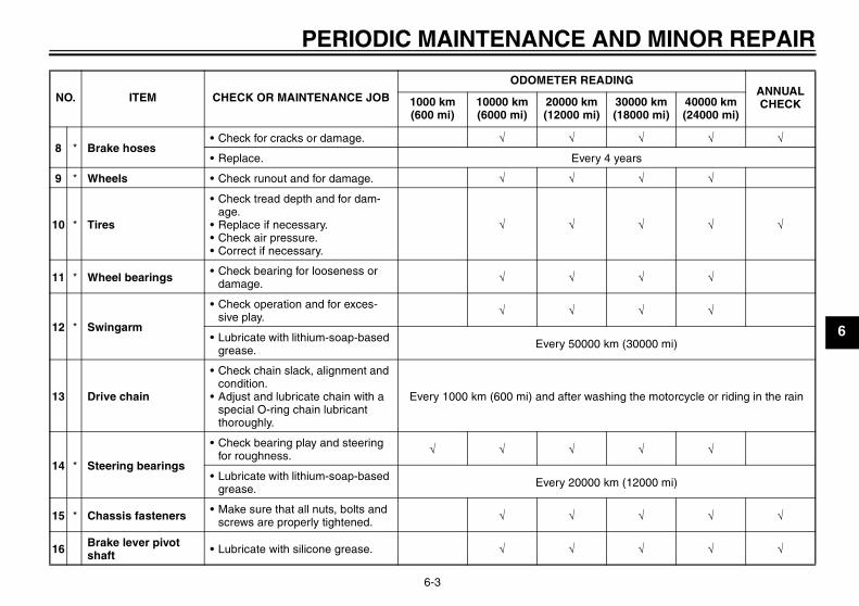
8 * Brake hoses• Check for cracks or damage. √ √ √ √ √
• Replace. Every 4 years
9 * Wheels • Check runout and for damage. √ √ √ √
10 * Tires
• Check tread depth and for dam-age.
• Replace if necessary.• Check air pressure.• Correct if necessary.
√ √ √ √ √
11 * Wheel bearings • Check bearing for looseness or damage. √ √ √ √
12 * Swingarm
• Check operation and for exces-sive play. √ √ √ √
• Lubricate with lithium-soap-based grease. Every 50000 km (30000 mi)
13 Drive chain
• Check chain slack, alignment and condition.
• Adjust and lubricate chain with a special O-ring chain lubricant thoroughly.
Every 1000 km (600 mi) and after washing the motorcycle or riding in the rain
14 * Steering bearings
• Check bearing play and steering for roughness. √ √ √ √ √
• Lubricate with lithium-soap-based grease. Every 20000 km (12000 mi)
15 * Chassis fasteners • Make sure that all nuts, bolts and screws are properly tightened. √ √ √ √ √
16 Brake lever pivot shaft • Lubricate with silicone grease. √ √ √ √ √
NO. ITEM CHECK OR MAINTENANCE JOB
ODOMETER READINGANNUAL CHECK1000 km
(600 mi)10000 km (6000 mi)
20000 km (12000 mi)
30000 km (18000 mi)
40000 km (24000 mi)
U5WME5E0.book Page 3 Wednesday, December 5, 2007 10:30 AM
PERIODIC MAINTENANCE AND MINOR REPAIR
6-4
6
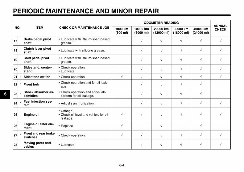
17 Brake pedal pivot shaft
• Lubricate with lithium-soap-based grease. √ √ √ √ √
18 Clutch lever pivot shaft • Lubricate with silicone grease. √ √ √ √ √
19 Shift pedal pivot shaft
• Lubricate with lithium-soap-based grease. √ √ √ √ √
20 Sidestand, center-stand
• Check operation.• Lubricate. √ √ √ √ √
21 * Sidestand switch • Check operation. √ √ √ √ √ √
22 * Front fork • Check operation and for oil leak-age. √ √ √ √
23 * Shock absorber as-semblies
• Check operation and shock ab-sorbers for oil leakage. √ √ √ √
24 * Fuel injection sys-tem • Adjust synchronization. √ √ √ √ √
25 Engine oil• Change.• Check oil level and vehicle for oil
leakage.√ √ √ √ √ √
26 Engine oil filter ele-ment • Replace. √ √ √
27 * Front and rear brake switches • Check operation. √ √ √ √ √ √
28 Moving parts and cables • Lubricate. √ √ √ √ √
NO. ITEM CHECK OR MAINTENANCE JOB
ODOMETER READINGANNUAL CHECK1000 km
(600 mi)10000 km (6000 mi)
20000 km (12000 mi)
30000 km (18000 mi)
40000 km (24000 mi)
U5WME5E0.book Page 4 Wednesday, December 5, 2007 10:30 AM
PERIODIC MAINTENANCE AND MINOR REPAIR
6-5
6EAU36771
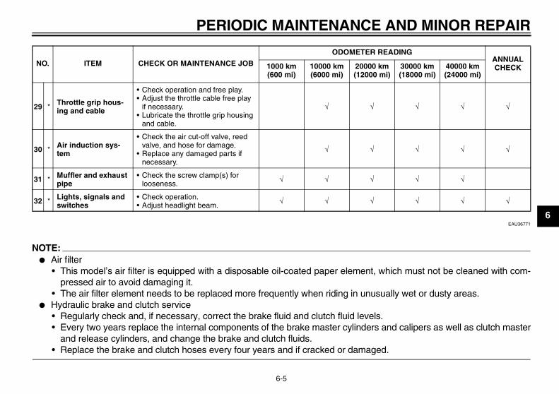
NOTE:� Air filter
• This model’s air filter is equipped with a disposable oil-coated paper element, which must not be cleaned with com-pressed air to avoid damaging it.
• The air filter element needs to be replaced more frequently when riding in unusually wet or dusty areas.� Hydraulic brake and clutch service
• Regularly check and, if necessary, correct the brake fluid and clutch fluid levels.• Every two years replace the internal components of the brake master cylinders and calipers as well as clutch master
and release cylinders, and change the brake and clutch fluids.• Replace the brake and clutch hoses every four years and if cracked or damaged.
29 * Throttle grip hous-ing and cable
• Check operation and free play.• Adjust the throttle cable free play
if necessary.• Lubricate the throttle grip housing
and cable.
√ √ √ √ √
30 * Air induction sys-tem
• Check the air cut-off valve, reed valve, and hose for damage.
• Replace any damaged parts if necessary.
√ √ √ √ √
31 * Muffler and exhaust pipe
• Check the screw clamp(s) for looseness. √ √ √ √ √
32 * Lights, signals and switches
• Check operation.• Adjust headlight beam. √ √ √ √ √ √
NO. ITEM CHECK OR MAINTENANCE JOB
ODOMETER READINGANNUAL CHECK1000 km
(600 mi)10000 km (6000 mi)
20000 km (12000 mi)
30000 km (18000 mi)
40000 km (24000 mi)
U5WME5E0.book Page 5 Wednesday, December 5, 2007 10:30 AM
PERIODIC MAINTENANCE AND MINOR REPAIR
6-6
6
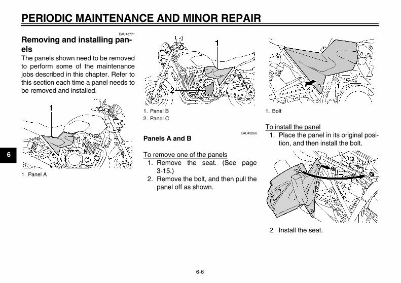
EAU18771
Removing and installing pan-els The panels shown need to be removedto perform some of the maintenancejobs described in this chapter. Refer tothis section each time a panel needs tobe removed and installed.
EAU43260
Panels A and B
To remove one of the panels1. Remove the seat. (See page
3-15.)2. Remove the bolt, and then pull the
panel off as shown.
To install the panel1. Place the panel in its original posi-
tion, and then install the bolt.
2. Install the seat.
1. Panel A
1. Panel B2. Panel C
1. Bolt
U5WME5E0.book Page 6 Wednesday, December 5, 2007 10:30 AM
PERIODIC MAINTENANCE AND MINOR REPAIR
6-7
6
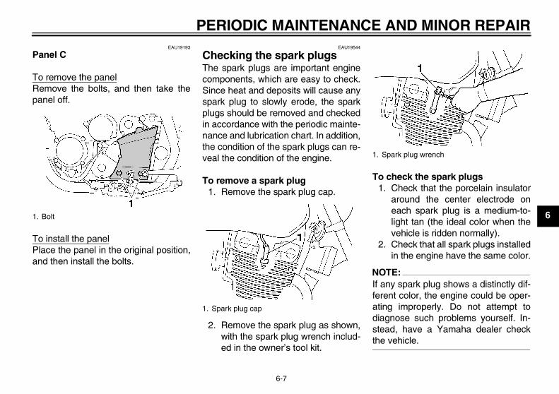
EAU19193
Panel C
To remove the panelRemove the bolts, and then take thepanel off.
To install the panelPlace the panel in the original position,and then install the bolts.
EAU19544
Checking the spark plugs The spark plugs are important enginecomponents, which are easy to check.Since heat and deposits will cause anyspark plug to slowly erode, the sparkplugs should be removed and checkedin accordance with the periodic mainte-nance and lubrication chart. In addition,the condition of the spark plugs can re-veal the condition of the engine.
To remove a spark plug1. Remove the spark plug cap.
2. Remove the spark plug as shown,with the spark plug wrench includ-ed in the owner’s tool kit.
To check the spark plugs1. Check that the porcelain insulator
around the center electrode oneach spark plug is a medium-to-light tan (the ideal color when thevehicle is ridden normally).
2. Check that all spark plugs installedin the engine have the same color.
NOTE:If any spark plug shows a distinctly dif-ferent color, the engine could be oper-ating improperly. Do not attempt todiagnose such problems yourself. In-stead, have a Yamaha dealer checkthe vehicle.
1. Bolt
1. Spark plug cap
1. Spark plug wrench
U5WME5E0.book Page 7 Wednesday, December 5, 2007 10:30 AM
PERIODIC MAINTENANCE AND MINOR REPAIR
6-8
6
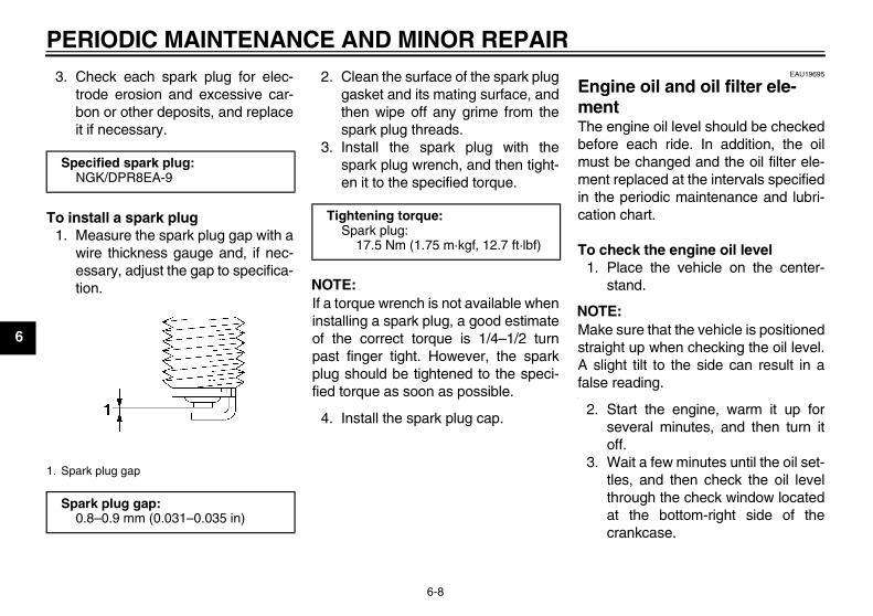
3. Check each spark plug for elec-trode erosion and excessive car-bon or other deposits, and replaceit if necessary.
To install a spark plug1. Measure the spark plug gap with a
wire thickness gauge and, if nec-essary, adjust the gap to specifica-tion.
2. Clean the surface of the spark pluggasket and its mating surface, andthen wipe off any grime from thespark plug threads.
3. Install the spark plug with thespark plug wrench, and then tight-en it to the specified torque.
NOTE:If a torque wrench is not available wheninstalling a spark plug, a good estimateof the correct torque is 1/4–1/2 turnpast finger tight. However, the sparkplug should be tightened to the speci-fied torque as soon as possible.
4. Install the spark plug cap.
EAU19695
Engine oil and oil filter ele-ment The engine oil level should be checkedbefore each ride. In addition, the oilmust be changed and the oil filter ele-ment replaced at the intervals specifiedin the periodic maintenance and lubri-cation chart.
To check the engine oil level1. Place the vehicle on the center-
stand.
NOTE:Make sure that the vehicle is positionedstraight up when checking the oil level.A slight tilt to the side can result in afalse reading.
2. Start the engine, warm it up forseveral minutes, and then turn itoff.
3. Wait a few minutes until the oil set-tles, and then check the oil levelthrough the check window locatedat the bottom-right side of thecrankcase.
Specified spark plug:NGK/DPR8EA-9
1. Spark plug gap
Spark plug gap:0.8–0.9 mm (0.031–0.035 in)
Tightening torque:Spark plug:
17.5 Nm (1.75 m·kgf, 12.7 ft·lbf)
U5WME5E0.book Page 8 Wednesday, December 5, 2007 10:30 AM
PERIODIC MAINTENANCE AND MINOR REPAIR
6-9
6
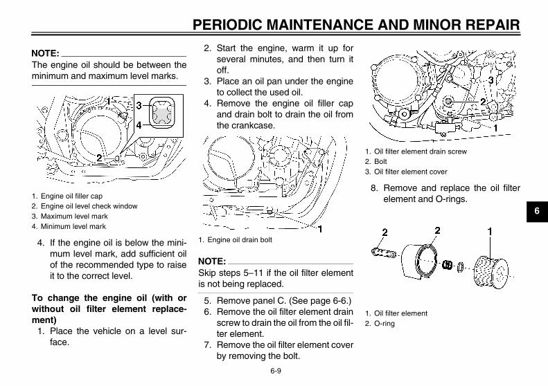
NOTE:The engine oil should be between theminimum and maximum level marks.
4. If the engine oil is below the mini-mum level mark, add sufficient oilof the recommended type to raiseit to the correct level.
To change the engine oil (with orwithout oil filter element replace-ment)
1. Place the vehicle on a level sur-face.
2. Start the engine, warm it up forseveral minutes, and then turn itoff.
3. Place an oil pan under the engineto collect the used oil.
4. Remove the engine oil filler capand drain bolt to drain the oil fromthe crankcase.
NOTE:Skip steps 5–11 if the oil filter elementis not being replaced.
5. Remove panel C. (See page 6-6.)6. Remove the oil filter element drain
screw to drain the oil from the oil fil-ter element.
7. Remove the oil filter element coverby removing the bolt.
8. Remove and replace the oil filterelement and O-rings.1. Engine oil filler cap
2. Engine oil level check window3. Maximum level mark4. Minimum level mark
1. Engine oil drain bolt
1. Oil filter element drain screw2. Bolt3. Oil filter element cover
1. Oil filter element2. O-ring
U5WME5E0.book Page 9 Wednesday, December 5, 2007 10:30 AM
PERIODIC MAINTENANCE AND MINOR REPAIR
6-10
6
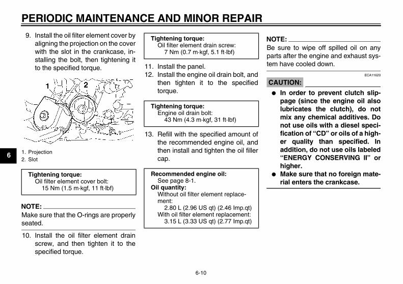
9. Install the oil filter element cover byaligning the projection on the coverwith the slot in the crankcase, in-stalling the bolt, then tightening itto the specified torque.
NOTE:Make sure that the O-rings are properlyseated.
10. Install the oil filter element drainscrew, and then tighten it to thespecified torque.
11. Install the panel.12. Install the engine oil drain bolt, and
then tighten it to the specifiedtorque.
13. Refill with the specified amount ofthe recommended engine oil, andthen install and tighten the oil fillercap.
NOTE:Be sure to wipe off spilled oil on anyparts after the engine and exhaust sys-tem have cooled down.
CAUTION:ECA11620
� In order to prevent clutch slip-page (since the engine oil alsolubricates the clutch), do notmix any chemical additives. Donot use oils with a diesel speci-fication of “CD” or oils of a high-er quality than specified. Inaddition, do not use oils labeled“ENERGY CONSERVING II” orhigher.
� Make sure that no foreign mate-rial enters the crankcase.
1. Projection2. Slot
Tightening torque:Oil filter element cover bolt:
15 Nm (1.5 m·kgf, 11 ft·lbf)
Tightening torque:Oil filter element drain screw:
7 Nm (0.7 m·kgf, 5.1 ft·lbf)
Tightening torque:Engine oil drain bolt:
43 Nm (4.3 m·kgf, 31 ft·lbf)
Recommended engine oil:See page 8-1.
Oil quantity:Without oil filter element replace-ment:
2.80 L (2.96 US qt) (2.46 Imp.qt)With oil filter element replacement:
3.15 L (3.33 US qt) (2.77 Imp.qt)
U5WME5E0.book Page 10 Wednesday, December 5, 2007 10:30 AM
PERIODIC MAINTENANCE AND MINOR REPAIR
6-11
6
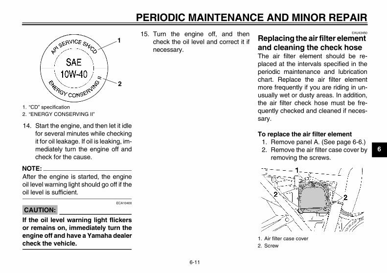
14. Start the engine, and then let it idlefor several minutes while checkingit for oil leakage. If oil is leaking, im-mediately turn the engine off andcheck for the cause.
NOTE:After the engine is started, the engineoil level warning light should go off if theoil level is sufficient.
CAUTION:ECA10400
If the oil level warning light flickersor remains on, immediately turn theengine off and have a Yamaha dealercheck the vehicle.
15. Turn the engine off, and thencheck the oil level and correct it ifnecessary.
EAU43450
Replacing the air filter element and cleaning the check hose The air filter element should be re-placed at the intervals specified in theperiodic maintenance and lubricationchart. Replace the air filter elementmore frequently if you are riding in un-usually wet or dusty areas. In addition,the air filter check hose must be fre-quently checked and cleaned if neces-sary.
To replace the air filter element1. Remove panel A. (See page 6-6.)2. Remove the air filter case cover by
removing the screws.
1. “CD” specification2. “ENERGY CONSERVING II”
1
2
1. Air filter case cover2. Screw
U5WME5E0.book Page 11 Wednesday, December 5, 2007 10:30 AM
PERIODIC MAINTENANCE AND MINOR REPAIR
6-12
6
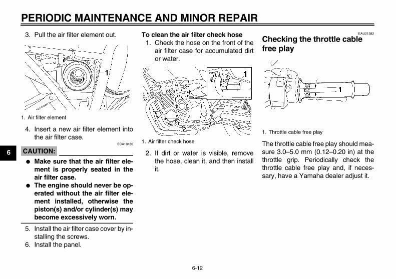
3. Pull the air filter element out.
4. Insert a new air filter element intothe air filter case.
CAUTION:ECA10480
� Make sure that the air filter ele-ment is properly seated in theair filter case.
� The engine should never be op-erated without the air filter ele-ment installed, otherwise thepiston(s) and/or cylinder(s) maybecome excessively worn.
5. Install the air filter case cover by in-stalling the screws.
6. Install the panel.
To clean the air filter check hose1. Check the hose on the front of the
air filter case for accumulated dirtor water.
2. If dirt or water is visible, removethe hose, clean it, and then installit.
EAU21382
Checking the throttle cable free play
The throttle cable free play should mea-sure 3.0–5.0 mm (0.12–0.20 in) at thethrottle grip. Periodically check thethrottle cable free play and, if neces-sary, have a Yamaha dealer adjust it.
1. Air filter element
1. Air filter check hose
1. Throttle cable free play
U5WME5E0.book Page 12 Wednesday, December 5, 2007 10:30 AM
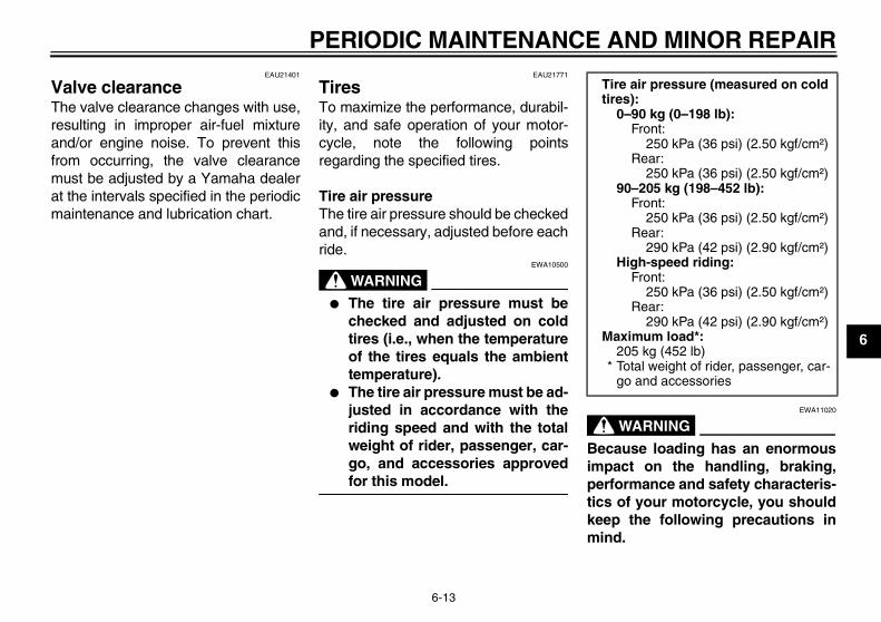
PERIODIC MAINTENANCE AND MINOR REPAIR
6-13
6
EAU21401
Valve clearance The valve clearance changes with use,resulting in improper air-fuel mixtureand/or engine noise. To prevent thisfrom occurring, the valve clearancemust be adjusted by a Yamaha dealerat the intervals specified in the periodicmaintenance and lubrication chart.
EAU21771
Tires To maximize the performance, durabil-ity, and safe operation of your motor-cycle, note the following pointsregarding the specified tires.
Tire air pressureThe tire air pressure should be checkedand, if necessary, adjusted before eachride.
WARNINGEWA10500
� The tire air pressure must bechecked and adjusted on coldtires (i.e., when the temperatureof the tires equals the ambienttemperature).
� The tire air pressure must be ad-justed in accordance with theriding speed and with the totalweight of rider, passenger, car-go, and accessories approvedfor this model.
WARNINGEWA11020
Because loading has an enormousimpact on the handling, braking,performance and safety characteris-tics of your motorcycle, you shouldkeep the following precautions inmind.
Tire air pressure (measured on cold tires):
0–90 kg (0–198 lb):Front:
250 kPa (36 psi) (2.50 kgf/cm²)Rear:
250 kPa (36 psi) (2.50 kgf/cm²)90–205 kg (198–452 lb):
Front:250 kPa (36 psi) (2.50 kgf/cm²)
Rear:290 kPa (42 psi) (2.90 kgf/cm²)
High-speed riding:Front:
250 kPa (36 psi) (2.50 kgf/cm²)Rear:
290 kPa (42 psi) (2.90 kgf/cm²)Maximum load*:
205 kg (452 lb)* Total weight of rider, passenger, car-
go and accessories
U5WME5E0.book Page 13 Wednesday, December 5, 2007 10:30 AM
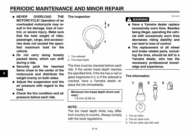
PERIODIC MAINTENANCE AND MINOR REPAIR
6-14
6
� NEVER OVERLOAD THEMOTORCYCLE! Operation of anoverloaded motorcycle may re-sult in tire damage, loss of con-trol, or severe injury. Make surethat the total weight of rider,passenger, cargo, and accesso-ries does not exceed the speci-fied maximum load for thevehicle.
� Do not carry along looselypacked items, which can shiftduring a ride.
� Securely pack the heaviestitems close to the center of themotorcycle and distribute theweight evenly on both sides.
� Adjust the suspension and tireair pressure with regard to theload.
� Check the tire condition and airpressure before each ride.
Tire inspection
The tires must be checked before eachride. If the center tread depth reachesthe specified limit, if the tire has a nail orglass fragments in it, or if the sidewall iscracked, have a Yamaha dealer re-place the tire immediately.
NOTE:The tire tread depth limits may differfrom country to country. Always complywith the local regulations.
WARNINGEWA10470
� Have a Yamaha dealer replaceexcessively worn tires. Besidesbeing illegal, operating the vehi-cle with excessively worn tiresdecreases riding stability andcan lead to loss of control.
� The replacement of all wheeland brake related parts, includ-ing the tires, should be left to aYamaha dealer, who has thenecessary professional knowl-edge and experience.
Tire information
1. Tire sidewall2. Tire tread depth
Minimum tire tread depth (front and rear):
1.6 mm (0.06 in)
1. Tire air valve2. Tire air valve core3. Tire air valve cap with seal
U5WME5E0.book Page 14 Wednesday, December 5, 2007 10:30 AM
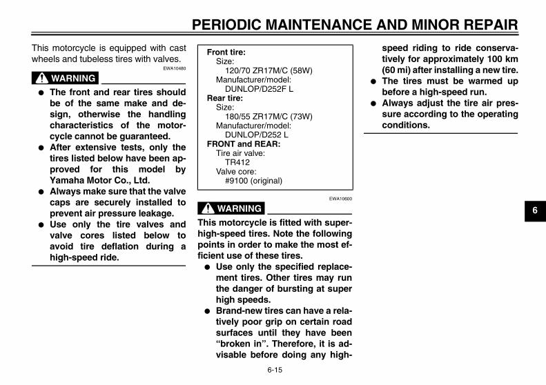
PERIODIC MAINTENANCE AND MINOR REPAIR
6-15
6
This motorcycle is equipped with castwheels and tubeless tires with valves.
WARNINGEWA10480
� The front and rear tires shouldbe of the same make and de-sign, otherwise the handlingcharacteristics of the motor-cycle cannot be guaranteed.
� After extensive tests, only thetires listed below have been ap-proved for this model byYamaha Motor Co., Ltd.
� Always make sure that the valvecaps are securely installed toprevent air pressure leakage.
� Use only the tire valves andvalve cores listed below toavoid tire deflation during ahigh-speed ride.
WARNINGEWA10600
This motorcycle is fitted with super-high-speed tires. Note the followingpoints in order to make the most ef-ficient use of these tires.
� Use only the specified replace-ment tires. Other tires may runthe danger of bursting at superhigh speeds.
� Brand-new tires can have a rela-tively poor grip on certain roadsurfaces until they have been“broken in”. Therefore, it is ad-visable before doing any high-
speed riding to ride conserva-tively for approximately 100 km(60 mi) after installing a new tire.
� The tires must be warmed upbefore a high-speed run.
� Always adjust the tire air pres-sure according to the operatingconditions.
Front tire:Size:
120/70 ZR17M/C (58W)Manufacturer/model:
DUNLOP/D252F LRear tire:
Size:180/55 ZR17M/C (73W)
Manufacturer/model:DUNLOP/D252 L
FRONT and REAR:Tire air valve:
TR412Valve core:
#9100 (original)
U5WME5E0.book Page 15 Wednesday, December 5, 2007 10:30 AM
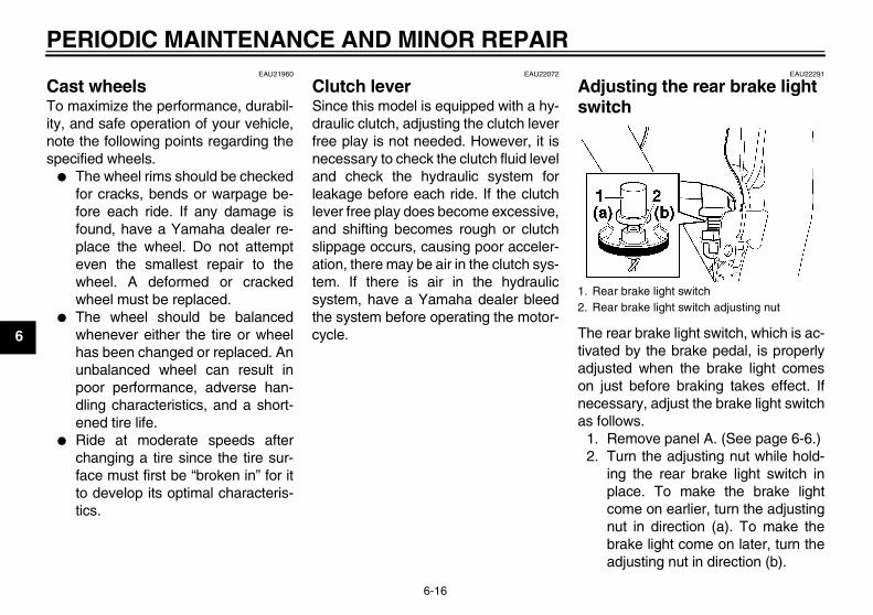
PERIODIC MAINTENANCE AND MINOR REPAIR
6-16
6
EAU21960
Cast wheels To maximize the performance, durabil-ity, and safe operation of your vehicle,note the following points regarding thespecified wheels.
� The wheel rims should be checkedfor cracks, bends or warpage be-fore each ride. If any damage isfound, have a Yamaha dealer re-place the wheel. Do not attempteven the smallest repair to thewheel. A deformed or crackedwheel must be replaced.
� The wheel should be balancedwhenever either the tire or wheelhas been changed or replaced. Anunbalanced wheel can result inpoor performance, adverse han-dling characteristics, and a short-ened tire life.
� Ride at moderate speeds afterchanging a tire since the tire sur-face must first be “broken in” for itto develop its optimal characteris-tics.
EAU22072
Clutch lever Since this model is equipped with a hy-draulic clutch, adjusting the clutch leverfree play is not needed. However, it isnecessary to check the clutch fluid leveland check the hydraulic system forleakage before each ride. If the clutchlever free play does become excessive,and shifting becomes rough or clutchslippage occurs, causing poor acceler-ation, there may be air in the clutch sys-tem. If there is air in the hydraulicsystem, have a Yamaha dealer bleedthe system before operating the motor-cycle.
EAU22291
Adjusting the rear brake light switch
The rear brake light switch, which is ac-tivated by the brake pedal, is properlyadjusted when the brake light comeson just before braking takes effect. Ifnecessary, adjust the brake light switchas follows.
1. Remove panel A. (See page 6-6.)2. Turn the adjusting nut while hold-
ing the rear brake light switch inplace. To make the brake lightcome on earlier, turn the adjustingnut in direction (a). To make thebrake light come on later, turn theadjusting nut in direction (b).
1. Rear brake light switch2. Rear brake light switch adjusting nut
U5WME5E0.book Page 16 Wednesday, December 5, 2007 10:30 AM
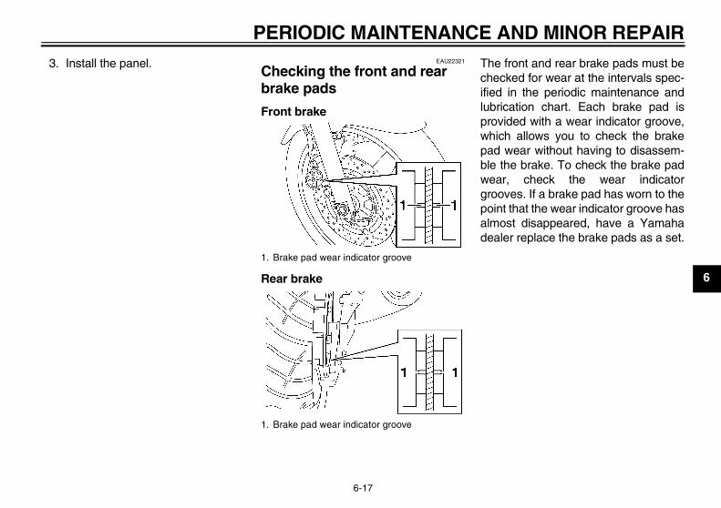
PERIODIC MAINTENANCE AND MINOR REPAIR
6-17
6
3. Install the panel. EAU22321
Checking the front and rear brake pads
Front brake
Rear brake
The front and rear brake pads must bechecked for wear at the intervals spec-ified in the periodic maintenance andlubrication chart. Each brake pad isprovided with a wear indicator groove,which allows you to check the brakepad wear without having to disassem-ble the brake. To check the brake padwear, check the wear indicatorgrooves. If a brake pad has worn to thepoint that the wear indicator groove hasalmost disappeared, have a Yamahadealer replace the brake pads as a set.
1. Brake pad wear indicator groove
1. Brake pad wear indicator groove
U5WME5E0.book Page 17 Wednesday, December 5, 2007 10:30 AM
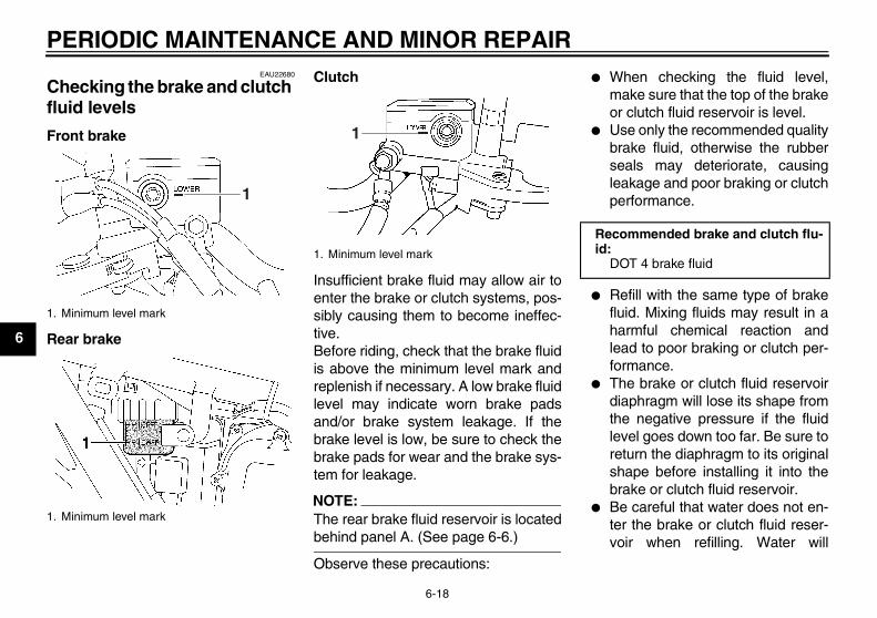
PERIODIC MAINTENANCE AND MINOR REPAIR
6-18
6
EAU22680
Checking the brake and clutch fluid levels
Front brake
Rear brake
Clutch
Insufficient brake fluid may allow air toenter the brake or clutch systems, pos-sibly causing them to become ineffec-tive.Before riding, check that the brake fluidis above the minimum level mark andreplenish if necessary. A low brake fluidlevel may indicate worn brake padsand/or brake system leakage. If thebrake level is low, be sure to check thebrake pads for wear and the brake sys-tem for leakage.
NOTE:The rear brake fluid reservoir is locatedbehind panel A. (See page 6-6.)
Observe these precautions:
� When checking the fluid level,make sure that the top of the brakeor clutch fluid reservoir is level.
� Use only the recommended qualitybrake fluid, otherwise the rubberseals may deteriorate, causingleakage and poor braking or clutchperformance.
� Refill with the same type of brakefluid. Mixing fluids may result in aharmful chemical reaction andlead to poor braking or clutch per-formance.
� The brake or clutch fluid reservoirdiaphragm will lose its shape fromthe negative pressure if the fluidlevel goes down too far. Be sure toreturn the diaphragm to its originalshape before installing it into thebrake or clutch fluid reservoir.
� Be careful that water does not en-ter the brake or clutch fluid reser-voir when refilling. Water will
1. Minimum level mark
1. Minimum level mark
1
1. Minimum level mark
1
Recommended brake and clutch flu-id:
DOT 4 brake fluid
U5WME5E0.book Page 18 Wednesday, December 5, 2007 10:30 AM
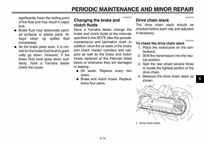
PERIODIC MAINTENANCE AND MINOR REPAIR
6-19
6
significantly lower the boiling pointof the fluid and may result in vaporlock.
� Brake fluid may deteriorate paint-ed surfaces or plastic parts. Al-ways clean up spilled fluidimmediately.
� As the brake pads wear, it is nor-mal for the brake fluid level to grad-ually go down. However, if thebrake fluid level goes down sud-denly, have a Yamaha dealercheck the cause.
EAU22750
Changing the brake and clutch fluids Have a Yamaha dealer change thebrake and clutch fluids at the intervalsspecified in the NOTE after the periodicmaintenance and lubrication chart. Inaddition, have the oil seals of the brakeand clutch master cylinders and cali-pers as well as the brake and clutchhoses replaced at the intervals listedbelow or whenever they are damagedor leaking.
� Oil seals: Replace every twoyears.
� Brake and clutch hoses: Replaceevery four years.
EAU22760
Drive chain slack The drive chain slack should bechecked before each ride and adjustedif necessary.
EAU22793
To check the drive chain slack1. Place the motorcycle on the cen-
terstand.2. Shift the transmission into the neu-
tral position.3. Spin the rear wheel several times
to locate the tightest portion of thedrive chain.
4. Measure the drive chain slack asshown.
1. Drive chain slack
U5WME5E0.book Page 19 Wednesday, December 5, 2007 10:30 AM
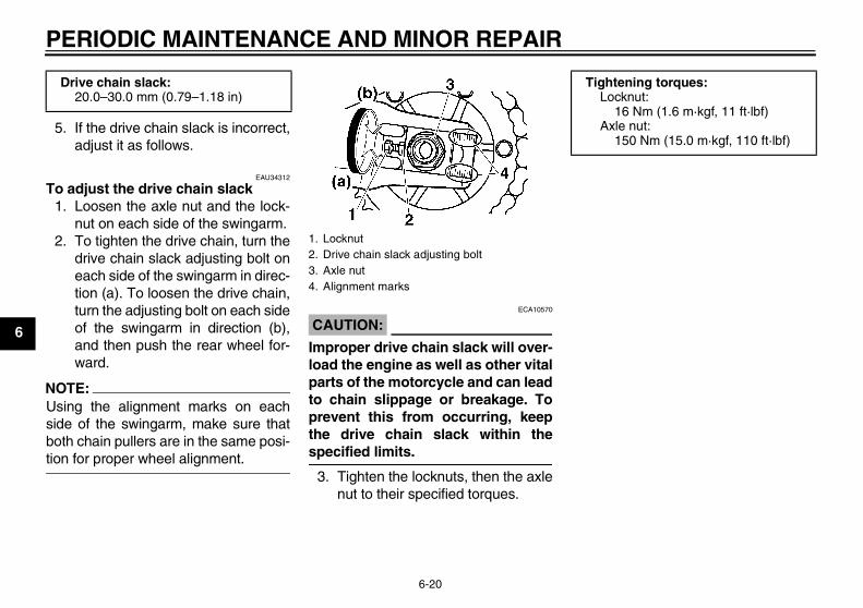
PERIODIC MAINTENANCE AND MINOR REPAIR
6-20
6
5. If the drive chain slack is incorrect,adjust it as follows.
EAU34312
To adjust the drive chain slack1. Loosen the axle nut and the lock-
nut on each side of the swingarm.2. To tighten the drive chain, turn the
drive chain slack adjusting bolt oneach side of the swingarm in direc-tion (a). To loosen the drive chain,turn the adjusting bolt on each sideof the swingarm in direction (b),and then push the rear wheel for-ward.
NOTE:Using the alignment marks on eachside of the swingarm, make sure thatboth chain pullers are in the same posi-tion for proper wheel alignment.
CAUTION:ECA10570
Improper drive chain slack will over-load the engine as well as other vitalparts of the motorcycle and can leadto chain slippage or breakage. Toprevent this from occurring, keepthe drive chain slack within thespecified limits.
3. Tighten the locknuts, then the axlenut to their specified torques.
Drive chain slack:20.0–30.0 mm (0.79–1.18 in)
1. Locknut2. Drive chain slack adjusting bolt3. Axle nut4. Alignment marks
Tightening torques:Locknut:
16 Nm (1.6 m·kgf, 11 ft·lbf)Axle nut:
150 Nm (15.0 m·kgf, 110 ft·lbf)
U5WME5E0.book Page 20 Wednesday, December 5, 2007 10:30 AM
PERIODIC MAINTENANCE AND MINOR REPAIR
6-21
6
EAU23022
Cleaning and lubricating the drive chain The drive chain must be cleaned andlubricated at the intervals specified inthe periodic maintenance and lubrica-tion chart, otherwise it will quickly wearout, especially when riding in dusty orwet areas. Service the drive chain asfollows.
CAUTION:ECA10581
The drive chain must be lubricatedafter washing the motorcycle andriding in the rain.
1. Clean the drive chain with kero-sene and a small soft brush.
CAUTION:ECA11120
To prevent damaging the O-rings, donot clean the drive chain with steamcleaners, high-pressure washers orinappropriate solvents.
2. Wipe the drive chain dry.3. Thoroughly lubricate the drive
chain with a special O-ring chainlubricant.
CAUTION:ECA11110
Do not use engine oil or any other lu-bricants for the drive chain, as theymay contain substances that coulddamage the O-rings.
EAU23100
Checking and lubricating the cables The operation of all control cables andthe condition of the cables should bechecked before each ride, and the ca-bles and cable ends should be lubricat-ed if necessary. If a cable is damagedor does not move smoothly, have aYamaha dealer check or replace it.
WARNINGEWA10720
Damage to the outer sheath may in-terfere with proper cable operationand will cause the inner cable torust. Replace a damaged cable assoon as possible to prevent unsafeconditions.
Recommended lubricant:Engine oil
U5WME5E0.book Page 21 Wednesday, December 5, 2007 10:30 AM
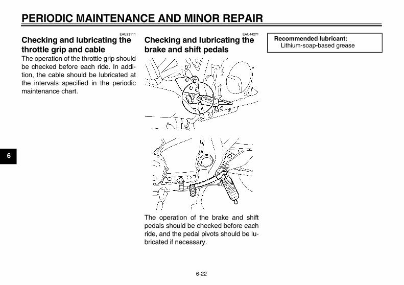
PERIODIC MAINTENANCE AND MINOR REPAIR
6-22
6
EAU23111
Checking and lubricating the throttle grip and cable The operation of the throttle grip shouldbe checked before each ride. In addi-tion, the cable should be lubricated atthe intervals specified in the periodicmaintenance chart.
EAU44271
Checking and lubricating the brake and shift pedals
The operation of the brake and shiftpedals should be checked before eachride, and the pedal pivots should be lu-bricated if necessary.
Recommended lubricant:Lithium-soap-based grease
U5WME5E0.book Page 22 Wednesday, December 5, 2007 10:30 AM
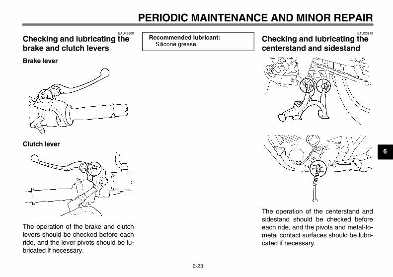
PERIODIC MAINTENANCE AND MINOR REPAIR
6-23
6
EAU43600
Checking and lubricating the brake and clutch levers
Brake lever
Clutch lever
The operation of the brake and clutchlevers should be checked before eachride, and the lever pivots should be lu-bricated if necessary.
EAU23212
Checking and lubricating the centerstand and sidestand
The operation of the centerstand andsidestand should be checked beforeeach ride, and the pivots and metal-to-metal contact surfaces should be lubri-cated if necessary.
Recommended lubricant:Silicone grease
U5WME5E0.book Page 23 Wednesday, December 5, 2007 10:30 AM
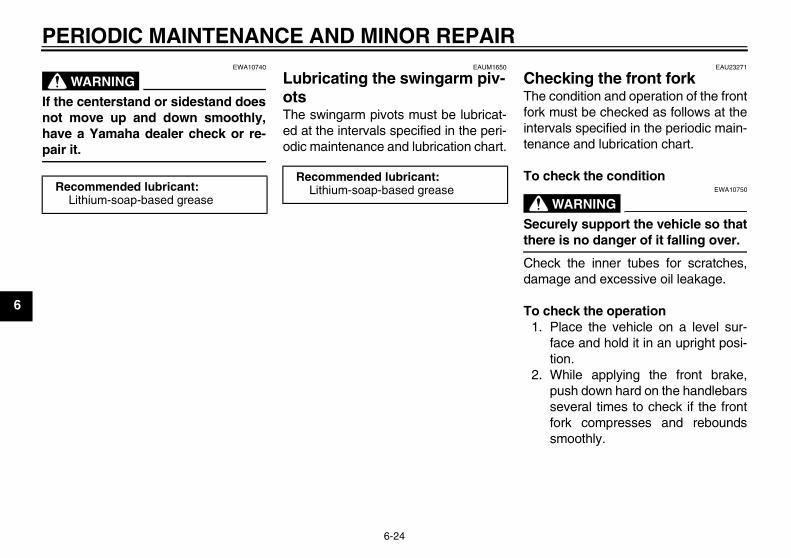
PERIODIC MAINTENANCE AND MINOR REPAIR
6-24
6
WARNINGEWA10740
If the centerstand or sidestand doesnot move up and down smoothly,have a Yamaha dealer check or re-pair it.
EAUM1650
Lubricating the swingarm piv-ots The swingarm pivots must be lubricat-ed at the intervals specified in the peri-odic maintenance and lubrication chart.
EAU23271
Checking the front fork The condition and operation of the frontfork must be checked as follows at theintervals specified in the periodic main-tenance and lubrication chart.
To check the condition
WARNINGEWA10750
Securely support the vehicle so thatthere is no danger of it falling over.
Check the inner tubes for scratches,damage and excessive oil leakage.
To check the operation1. Place the vehicle on a level sur-
face and hold it in an upright posi-tion.
2. While applying the front brake,push down hard on the handlebarsseveral times to check if the frontfork compresses and reboundssmoothly.
Recommended lubricant:Lithium-soap-based grease
Recommended lubricant:Lithium-soap-based grease
U5WME5E0.book Page 24 Wednesday, December 5, 2007 10:30 AM
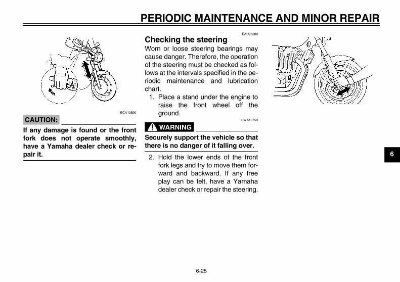
PERIODIC MAINTENANCE AND MINOR REPAIR
6-25
6
CAUTION:ECA10590
If any damage is found or the frontfork does not operate smoothly,have a Yamaha dealer check or re-pair it.
EAU23280
Checking the steering Worn or loose steering bearings maycause danger. Therefore, the operationof the steering must be checked as fol-lows at the intervals specified in the pe-riodic maintenance and lubricationchart.
1. Place a stand under the engine toraise the front wheel off theground.
WARNINGEWA10750
Securely support the vehicle so thatthere is no danger of it falling over.
2. Hold the lower ends of the frontfork legs and try to move them for-ward and backward. If any freeplay can be felt, have a Yamahadealer check or repair the steering.
U5WME5E0.book Page 25 Wednesday, December 5, 2007 10:30 AM
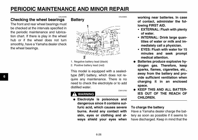
PERIODIC MAINTENANCE AND MINOR REPAIR
6-26
6
EAU23290
Checking the wheel bearings The front and rear wheel bearings mustbe checked at the intervals specified inthe periodic maintenance and lubrica-tion chart. If there is play in the wheelhub or if the wheel does not turnsmoothly, have a Yamaha dealer checkthe wheel bearings.
EAU33650
Battery
This model is equipped with a sealed-type (MF) battery, which does not re-quire any maintenance. There is noneed to check the electrolyte or to adddistilled water.
WARNINGEWA10760
� Electrolyte is poisonous anddangerous since it contains sul-furic acid, which causes severeburns. Avoid any contact withskin, eyes or clothing and al-ways shield your eyes when
working near batteries. In caseof contact, administer the fol-lowing FIRST AID.• EXTERNAL: Flush with plenty
of water.• INTERNAL: Drink large quan-
tities of water or milk and im-mediately call a physician.
• EYES: Flush with water for 15minutes and seek promptmedical attention.
� Batteries produce explosive hy-drogen gas. Therefore, keepsparks, flames, cigarettes, etc.,away from the battery and pro-vide sufficient ventilation whencharging it in an enclosedspace.
� KEEP THIS AND ALL BATTER-IES OUT OF THE REACH OFCHILDREN.
To charge the batteryHave a Yamaha dealer charge the bat-tery as soon as possible if it seems tohave discharged. Keep in mind that the
1. Negative battery lead (black)2. Positive battery lead (red)
1
2
U5WME5E0.book Page 26 Wednesday, December 5, 2007 10:30 AM
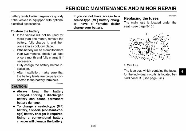
PERIODIC MAINTENANCE AND MINOR REPAIR
6-27
6
battery tends to discharge more quicklyif the vehicle is equipped with optionalelectrical accessories.
To store the battery1. If the vehicle will not be used for
more than one month, remove thebattery, fully charge it, and thenplace it in a cool, dry place.
2. If the battery will be stored for morethan two months, check it at leastonce a month and fully charge it ifnecessary.
3. Fully charge the battery before in-stallation.
4. After installation, make sure thatthe battery leads are properly con-nected to the battery terminals.
CAUTION:ECA10630
� Always keep the batterycharged. Storing a dischargedbattery can cause permanentbattery damage.
� To charge a sealed-type (MF)battery, a special (constant-volt-age) battery charger is required.Using a conventional batterycharger will damage the battery.
If you do not have access to asealed-type (MF) battery charg-er, have a Yamaha dealercharge your battery.
EAU43271
Replacing the fuses The main fuse is located under theseat. (See page 3-15.)
The fuse box, which contains the fusesfor the individual circuits, is located be-hind panel B. (See page 6-6.)
1. Main fuse
U5WME5E0.book Page 27 Wednesday, December 5, 2007 10:30 AM
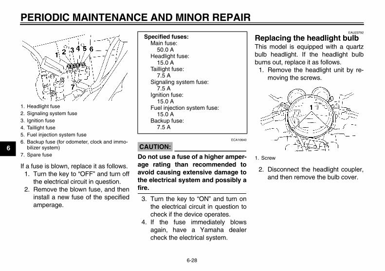
PERIODIC MAINTENANCE AND MINOR REPAIR
6-28
6
If a fuse is blown, replace it as follows.1. Turn the key to “OFF” and turn off
the electrical circuit in question.2. Remove the blown fuse, and then
install a new fuse of the specifiedamperage.
CAUTION:ECA10640
Do not use a fuse of a higher amper-age rating than recommended toavoid causing extensive damage tothe electrical system and possibly afire.
3. Turn the key to “ON” and turn onthe electrical circuit in question tocheck if the device operates.
4. If the fuse immediately blowsagain, have a Yamaha dealercheck the electrical system.
EAU23792
Replacing the headlight bulb This model is equipped with a quartzbulb headlight. If the headlight bulbburns out, replace it as follows.
1. Remove the headlight unit by re-moving the screws.
2. Disconnect the headlight coupler,and then remove the bulb cover.
1. Headlight fuse2. Signaling system fuse3. Ignition fuse4. Taillight fuse5. Fuel injection system fuse6. Backup fuse (for odometer, clock and immo-
bilizer system)7. Spare fuse
Specified fuses:Main fuse:
50.0 AHeadlight fuse:
15.0 ATaillight fuse:
7.5 ASignaling system fuse:
7.5 AIgnition fuse:
15.0 AFuel injection system fuse:
15.0 ABackup fuse:
7.5 A
1. Screw
U5WME5E0.book Page 28 Wednesday, December 5, 2007 10:30 AM
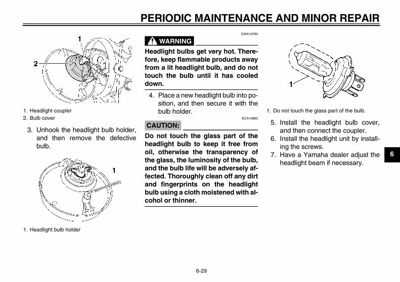
PERIODIC MAINTENANCE AND MINOR REPAIR
6-29
6
3. Unhook the headlight bulb holder,and then remove the defectivebulb.
WARNINGEWA10790
Headlight bulbs get very hot. There-fore, keep flammable products awayfrom a lit headlight bulb, and do nottouch the bulb until it has cooleddown.
4. Place a new headlight bulb into po-sition, and then secure it with thebulb holder.
CAUTION:ECA10660
Do not touch the glass part of theheadlight bulb to keep it free fromoil, otherwise the transparency ofthe glass, the luminosity of the bulb,and the bulb life will be adversely af-fected. Thoroughly clean off any dirtand fingerprints on the headlightbulb using a cloth moistened with al-cohol or thinner.
5. Install the headlight bulb cover,and then connect the coupler.
6. Install the headlight unit by install-ing the screws.
7. Have a Yamaha dealer adjust theheadlight beam if necessary.
1. Headlight coupler2. Bulb cover
1. Headlight bulb holder
1. Do not touch the glass part of the bulb.
U5WME5E0.book Page 29 Wednesday, December 5, 2007 10:30 AM
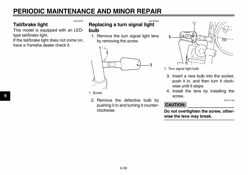
PERIODIC MAINTENANCE AND MINOR REPAIR
6-30
6
EAU24181
Tail/brake light This model is equipped with an LED-type tail/brake light.If the tail/brake light does not come on,have a Yamaha dealer check it.
EAU24202
Replacing a turn signal light bulb
1. Remove the turn signal light lensby removing the screw.
2. Remove the defective bulb bypushing it in and turning it counter-clockwise.
3. Insert a new bulb into the socket,push it in, and then turn it clock-wise until it stops.
4. Install the lens by installing thescrew.
CAUTION:ECA11190
Do not overtighten the screw, other-wise the lens may break.
1. Screw
1. Turn signal light bulb
U5WME5E0.book Page 30 Wednesday, December 5, 2007 10:30 AM
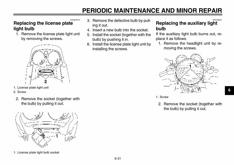
PERIODIC MAINTENANCE AND MINOR REPAIR
6-31
6
EAU24310
Replacing the license plate light bulb
1. Remove the license plate light unitby removing the screws.
2. Remove the socket (together withthe bulb) by pulling it out.
3. Remove the defective bulb by pull-ing it out.
4. Insert a new bulb into the socket.5. Install the socket (together with the
bulb) by pushing it in.6. Install the license plate light unit by
installing the screws.
EAU33541
Replacing the auxiliary light bulb If the auxiliary light bulb burns out, re-place it as follows.
1. Remove the headlight unit by re-moving the screws.
2. Remove the socket (together withthe bulb) by pulling it out.
1. License plate light unit2. Screw
1. License plate light bulb socket
1. Screw
U5WME5E0.book Page 31 Wednesday, December 5, 2007 10:30 AM
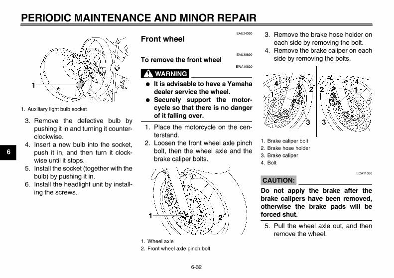
PERIODIC MAINTENANCE AND MINOR REPAIR
6-32
6
3. Remove the defective bulb bypushing it in and turning it counter-clockwise.
4. Insert a new bulb into the socket,push it in, and then turn it clock-wise until it stops.
5. Install the socket (together with thebulb) by pushing it in.
6. Install the headlight unit by install-ing the screws.
EAU24360
Front wheel
EAU38890
To remove the front wheel
WARNINGEWA10820
� It is advisable to have a Yamahadealer service the wheel.
� Securely support the motor-cycle so that there is no dangerof it falling over.
1. Place the motorcycle on the cen-terstand.
2. Loosen the front wheel axle pinchbolt, then the wheel axle and thebrake caliper bolts.
3. Remove the brake hose holder oneach side by removing the bolt.
4. Remove the brake caliper on eachside by removing the bolts.
CAUTION:ECA11050
Do not apply the brake after thebrake calipers have been removed,otherwise the brake pads will beforced shut.
5. Pull the wheel axle out, and thenremove the wheel.
1. Auxiliary light bulb socket
1. Wheel axle2. Front wheel axle pinch bolt
1. Brake caliper bolt2. Brake hose holder3. Brake caliper4. Bolt
U5WME5E0.book Page 32 Wednesday, December 5, 2007 10:30 AM
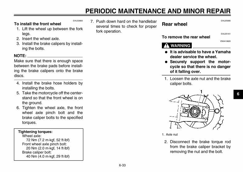
PERIODIC MAINTENANCE AND MINOR REPAIR
6-33
6
EAU33660
To install the front wheel1. Lift the wheel up between the fork
legs.2. Insert the wheel axle.3. Install the brake calipers by install-
ing the bolts.
NOTE:Make sure that there is enough spacebetween the brake pads before install-ing the brake calipers onto the brakediscs.
4. Install the brake hose holders byinstalling the bolts.
5. Take the motorcycle off the center-stand so that the front wheel is onthe ground.
6. Tighten the wheel axle, the frontwheel axle pinch bolt and thebrake caliper bolts to the specifiedtorques.
7. Push down hard on the handlebarseveral times to check for properfork operation.
EAU25080
Rear wheel
EAU25161
To remove the rear wheel
WARNINGEWA10820
� It is advisable to have a Yamahadealer service the wheel.
� Securely support the motor-cycle so that there is no dangerof it falling over.
1. Loosen the axle nut and the brakecaliper bolts.
2. Disconnect the brake torque rodfrom the brake caliper bracket byremoving the nut and the bolt.
Tightening torques:Wheel axle:
72 Nm (7.2 m·kgf, 52 ft·lbf)Front wheel axle pinch bolt:
20 Nm (2.0 m·kgf, 14 ft·lbf)Brake caliper bolt:
40 Nm (4.0 m·kgf, 29 ft·lbf)
1. Axle nut
U5WME5E0.book Page 33 Wednesday, December 5, 2007 10:30 AM
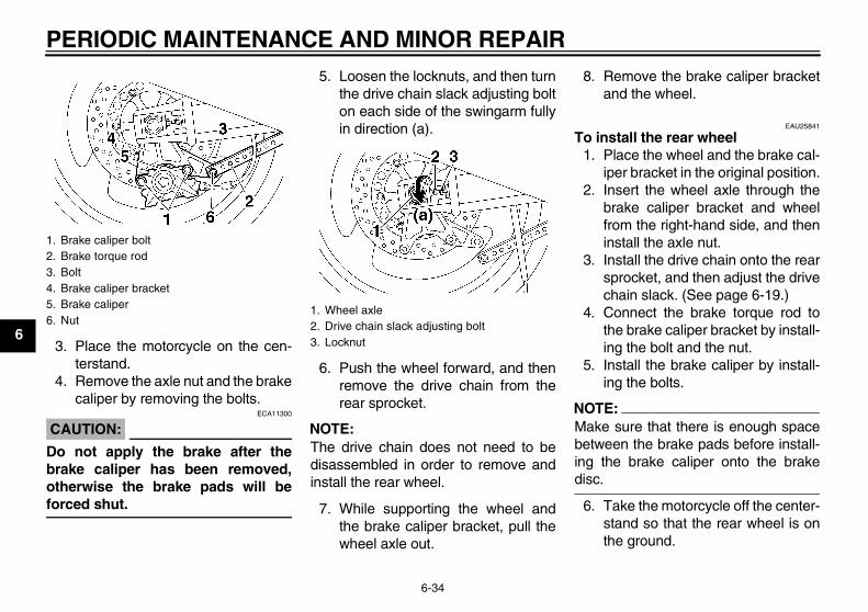
PERIODIC MAINTENANCE AND MINOR REPAIR
6-34
63. Place the motorcycle on the cen-
terstand.4. Remove the axle nut and the brake
caliper by removing the bolts.
CAUTION:ECA11300
Do not apply the brake after thebrake caliper has been removed,otherwise the brake pads will beforced shut.
5. Loosen the locknuts, and then turnthe drive chain slack adjusting bolton each side of the swingarm fullyin direction (a).
6. Push the wheel forward, and thenremove the drive chain from therear sprocket.
NOTE:The drive chain does not need to bedisassembled in order to remove andinstall the rear wheel.
7. While supporting the wheel andthe brake caliper bracket, pull thewheel axle out.
8. Remove the brake caliper bracketand the wheel.
EAU25841
To install the rear wheel1. Place the wheel and the brake cal-
iper bracket in the original position.2. Insert the wheel axle through the
brake caliper bracket and wheelfrom the right-hand side, and theninstall the axle nut.
3. Install the drive chain onto the rearsprocket, and then adjust the drivechain slack. (See page 6-19.)
4. Connect the brake torque rod tothe brake caliper bracket by install-ing the bolt and the nut.
5. Install the brake caliper by install-ing the bolts.
NOTE:Make sure that there is enough spacebetween the brake pads before install-ing the brake caliper onto the brakedisc.
6. Take the motorcycle off the center-stand so that the rear wheel is onthe ground.
1. Brake caliper bolt2. Brake torque rod3. Bolt4. Brake caliper bracket5. Brake caliper6. Nut
1. Wheel axle2. Drive chain slack adjusting bolt3. Locknut
U5WME5E0.book Page 34 Wednesday, December 5, 2007 10:30 AM
PERIODIC MAINTENANCE AND MINOR REPAIR
6-35
6
7. Tighten the axle nut, brake caliperbolts and brake torque rod nut tothe specified torques.
EAU25850
Troubleshooting Although Yamaha motorcycles receivea thorough inspection before shipmentfrom the factory, trouble may occur dur-ing operation. Any problem in the fuel,compression, or ignition systems, forexample, can cause poor starting andloss of power.The following troubleshooting chartrepresents a quick and easy procedurefor checking these vital systems your-self. However, should your motorcyclerequire any repair, take it to a Yamahadealer, whose skilled technicians havethe necessary tools, experience, andknow-how to service the motorcycleproperly.Use only genuine Yamaha replace-ment parts. Imitation parts may look likeYamaha parts, but they are often inferi-or, have a shorter service life and canlead to expensive repair bills.
Tightening torques:Axle nut:
150 Nm (15.0 m·kgf, 110 ft·lbf)Brake caliper bolt:
40 Nm (4.0 m·kgf, 29 ft·lbf)Brake torque rod nut:
23 Nm (2.3 m·kgf, 17 ft·lbf)
U5WME5E0.book Page 35 Wednesday, December 5, 2007 10:30 AM
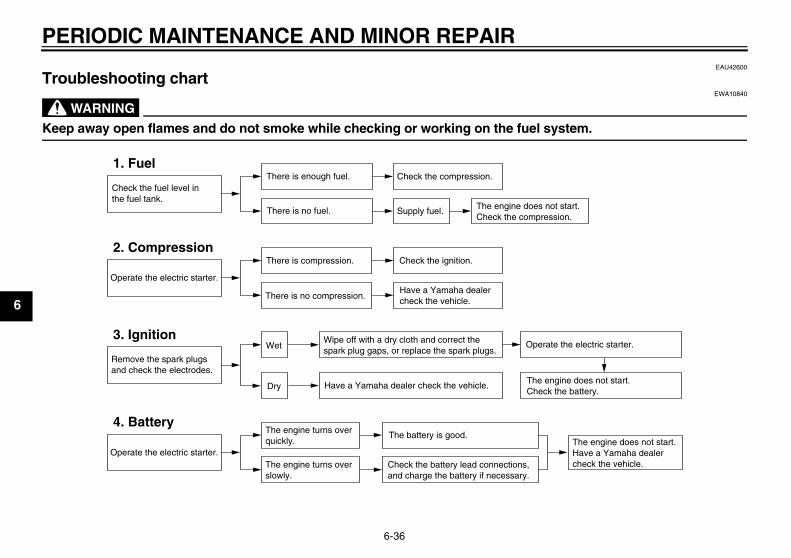
PERIODIC MAINTENANCE AND MINOR REPAIR
6-36
6
EAU42600
Troubleshooting chart
WARNINGEWA10840
Keep away open flames and do not smoke while checking or working on the fuel system.
Check the fuel level inthe fuel tank.
1. FuelThere is enough fuel.
There is no fuel.
Check the compression.
Supply fuel. The engine does not start. Check the compression.
Operate the electric starter.
2. CompressionThere is compression.
There is no compression.
Check the ignition.
Have a Yamaha dealercheck the vehicle.
Remove the spark plugsand check the electrodes.
3. Ignition Wipe off with a dry cloth and correct thespark plug gaps, or replace the spark plugs.
Have a Yamaha dealer check the vehicle.
The engine does not start.Have a Yamaha dealercheck the vehicle.
The engine does not start.Check the battery.
Operate the electric starter.
4. BatteryThe engine turns over quickly.
The engine turns over slowly.
The battery is good.
Check the battery lead connections,and charge the battery if necessary.
Dry
Wet Operate the electric starter.
U5WME5E0.book Page 36 Wednesday, December 5, 2007 10:30 AM
MOTORCYCLE CARE AND STORAGE
7-1
7
EAU37833
Matte color caution
CAUTION:ECA15192
Some models are equipped withmatte colored finished parts. Besure to consult a Yamaha dealer foradvice on what products to use be-fore cleaning the vehicle. Using abrush, harsh chemical products orcleaning compounds when cleaningthese parts will scratch or damagetheir surface. Wax also should notbe applied to any matte colored fin-ished parts.
EAU26012
Care While the open design of a motorcyclereveals the attractiveness of the tech-nology, it also makes it more vulnera-ble. Rust and corrosion can developeven if high-quality components areused. A rusty exhaust pipe may go un-noticed on a car, however, it detractsfrom the overall appearance of a motor-cycle. Frequent and proper care doesnot only comply with the terms of thewarranty, but it will also keep yourmotorcycle looking good, extend its lifeand optimize its performance.
Before cleaning1. Cover the muffler outlet with a
plastic bag after the engine hascooled down.
2. Make sure that all caps and coversas well as all electrical couplersand connectors, including thespark plug caps, are tightly in-stalled.
3. Remove extremely stubborn dirt,like oil burnt onto the crankcase,with a degreasing agent and abrush, but never apply such prod-
ucts onto seals, gaskets, sprock-ets, the drive chain and wheelaxles. Always rinse the dirt and de-greaser off with water.
Cleaning
CAUTION:ECA10771
� Avoid using strong acidic wheelcleaners, especially on spokedwheels. If such products areused on hard-to-remove dirt, donot leave the cleaner on the af-fected area any longer than in-structed. Also, thoroughly rinsethe area off with water, immedi-ately dry it, and then apply a cor-rosion protection spray.
� Improper cleaning can damageplastic parts such as cowlings,panels, windshields, headlightlenses, meter lenses, etc. Useonly a soft, clean cloth orsponge with mild detergent andwater to clean plastic.
� Do not use any harsh chemicalproducts on plastic parts. Besure to avoid using cloths orsponges which have been in
U5WME5E0.book Page 1 Wednesday, December 5, 2007 10:30 AM
MOTORCYCLE CARE AND STORAGE
7-2
7
contact with strong or abrasivecleaning products, solvent orthinner, fuel (gasoline), rust re-movers or inhibitors, brake flu-id, antifreeze or electrolyte.
� Do not use high-pressure wash-ers or steam-jet cleaners sincethey cause water seepage anddeterioration in the following ar-eas: seals (of wheel and swing-arm bearings, fork and brakes),electric components (couplers,connectors, instruments,switches and lights), breatherhoses and vents.
� For motorcycles equipped witha windshield: Do not use strongcleaners or hard sponges asthey will cause dulling orscratching. Some cleaning com-pounds for plastic may leavescratches on the windshield.Test the product on a small hid-den part of the windshield tomake sure that it does not leaveany marks. If the windshield is
scratched, use a quality plasticpolishing compound afterwashing.
After normal useRemove dirt with warm water, a milddetergent, and a soft, clean sponge,and then rinse thoroughly with cleanwater. Use a toothbrush or bottlebrushfor hard-to-reach areas. Stubborn dirtand insects will come off more easily ifthe area is covered with a wet cloth fora few minutes before cleaning.
After riding in the rain, near the sea oron salt-sprayed roadsSince sea salt or salt sprayed on roadsduring winter are extremely corrosive incombination with water, carry out thefollowing steps after each ride in therain, near the sea or on salt-sprayedroads.
NOTE:Salt sprayed on roads in the winter mayremain well into spring.
1. Clean the motorcycle with cold wa-ter and a mild detergent, after theengine has cooled down.
CAUTION:ECA10790
Do not use warm water since it in-creases the corrosive action of thesalt.
2. Apply a corrosion protection sprayon all metal, including chrome- andnickel-plated, surfaces to preventcorrosion.
After cleaning1. Dry the motorcycle with a chamois
or an absorbing cloth.2. Immediately dry the drive chain
and lubricate it to prevent it fromrusting.
3. Use a chrome polish to shinechrome, aluminum and stainless-steel parts, including the exhaustsystem. (Even the thermally in-duced discoloring of stainless-steel exhaust systems can be re-moved through polishing.)
U5WME5E0.book Page 2 Wednesday, December 5, 2007 10:30 AM
MOTORCYCLE CARE AND STORAGE
7-3
7
4. To prevent corrosion, it is recom-mended to apply a corrosion pro-tection spray on all metal,including chrome- and nickel-plat-ed, surfaces.
5. Use spray oil as a universal clean-er to remove any remaining dirt.
6. Touch up minor paint damagecaused by stones, etc.
7. Wax all painted surfaces.8. Let the motorcycle dry completely
before storing or covering it.
WARNINGEWA11130
� Make sure that there is no oil orwax on the brakes or tires.
� If necessary, clean the brakediscs and brake linings with aregular brake disc cleaner or ac-etone, and wash the tires withwarm water and a mild deter-gent. Before riding at higherspeeds, test the motorcycle’sbraking performance and cor-nering behavior.
CAUTION:ECA10800
� Apply spray oil and wax spar-ingly and make sure to wipe offany excess.
� Never apply oil or wax to anyrubber and plastic parts, buttreat them with a suitable careproduct.
� Avoid using abrasive polishingcompounds as they will wearaway the paint.
NOTE:Consult a Yamaha dealer for advice onwhat products to use.
EAU26180
Storage
Short-termAlways store your motorcycle in a cool,dry place and, if necessary, protect itagainst dust with a porous cover.
CAUTION:ECA10810
� Storing the motorcycle in apoorly ventilated room or cover-ing it with a tarp, while it is stillwet, will allow water and humid-ity to seep in and cause rust.
� To prevent corrosion, avoiddamp cellars, stables (becauseof the presence of ammonia)and areas where strong chemi-cals are stored.
Long-termBefore storing your motorcycle for sev-eral months:
1. Follow all the instructions in the“Care” section of this chapter.
2. Fill up the fuel tank and add fuelstabilizer (if available) to preventthe fuel tank from rusting and thefuel from deteriorating.
U5WME5E0.book Page 3 Wednesday, December 5, 2007 10:30 AM
MOTORCYCLE CARE AND STORAGE
7-4
7
3. Perform the following steps to pro-tect the cylinders, piston rings, etc.from corrosion.a. Remove the spark plug caps
and spark plugs.b. Pour a teaspoonful of engine oil
into each spark plug bore.c. Install the spark plug caps onto
the spark plugs, and then placethe spark plugs on the cylinderhead so that the electrodes aregrounded. (This will limit spark-ing during the next step.)
d. Turn the engine over severaltimes with the starter. (This willcoat the cylinder walls with oil.)
e. Remove the spark plug capsfrom the spark plugs, and theninstall the spark plugs and thespark plug caps.
WARNINGEWA10950
To prevent damage or injury fromsparking, make sure to ground thespark plug electrodes while turningthe engine over.
4. Lubricate all control cables and thepivoting points of all levers andpedals as well as of the side-stand/centerstand.
5. Check and, if necessary, correctthe tire air pressure, and then liftthe motorcycle so that both of itswheels are off the ground. Alterna-tively, turn the wheels a little everymonth in order to prevent the tiresfrom becoming degraded in onespot.
6. Cover the muffler outlet with aplastic bag to prevent moisturefrom entering it.
7. Remove the battery and fullycharge it. Store it in a cool, dryplace and charge it once a month.Do not store the battery in an ex-cessively cold or warm place [lessthan 0 °C (30 °F) or more than 30°C (90 °F)]. For more informationon storing the battery, see page6-26.
NOTE:Make any necessary repairs beforestoring the motorcycle.
U5WME5E0.book Page 4 Wednesday, December 5, 2007 10:30 AM
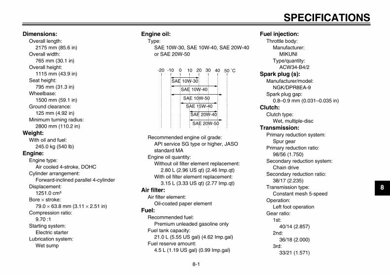
SPECIFICATIONS
8-1
8
Dimensions:Overall length:
2175 mm (85.6 in)Overall width:
765 mm (30.1 in)Overall height:
1115 mm (43.9 in)Seat height:
795 mm (31.3 in)Wheelbase:
1500 mm (59.1 in)Ground clearance:
125 mm (4.92 in)Minimum turning radius:
2800 mm (110.2 in)Weight:
With oil and fuel:245.0 kg (540 lb)
Engine:Engine type:
Air cooled 4-stroke, DOHCCylinder arrangement:
Forward-inclined parallel 4-cylinderDisplacement:
1251.0 cm³Bore × stroke:
79.0 × 63.8 mm (3.11 × 2.51 in)Compression ratio:
9.70 :1Starting system:
Electric starterLubrication system:
Wet sump
Engine oil:Type:
SAE 10W-30, SAE 10W-40, SAE 20W-40 or SAE 20W-50
Recommended engine oil grade:API service SG type or higher, JASO standard MA
Engine oil quantity:Without oil filter element replacement:
2.80 L (2.96 US qt) (2.46 Imp.qt)With oil filter element replacement:
3.15 L (3.33 US qt) (2.77 Imp.qt)Air filter:
Air filter element:Oil-coated paper element
Fuel:Recommended fuel:
Premium unleaded gasoline onlyFuel tank capacity:
21.0 L (5.55 US gal) (4.62 Imp.gal)Fuel reserve amount:
4.5 L (1.19 US gal) (0.99 Imp.gal)
Fuel injection:Throttle body:
Manufacturer:MIKUNI
Type/quantity:ACW34-B4/2
Spark plug (s):Manufacturer/model:
NGK/DPR8EA-9Spark plug gap:
0.8–0.9 mm (0.031–0.035 in)Clutch:
Clutch type:Wet, multiple-disc
Transmission:Primary reduction system:
Spur gearPrimary reduction ratio:
98/56 (1.750)Secondary reduction system:
Chain driveSecondary reduction ratio:
38/17 (2.235)Transmission type:
Constant mesh 5-speedOperation:
Left foot operationGear ratio:
1st:40/14 (2.857)
2nd:36/18 (2.000)
3rd:33/21 (1.571)
-20 -10 0 10 20 30 40 50 ˚C
SAE 10W-30
SAE 15W-40
SAE 20W-40
SAE 20W-50
SAE 10W-40
SAE 10W-50
U5WME5E0.book Page 1 Wednesday, December 5, 2007 10:30 AM
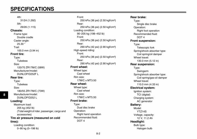
SPECIFICATIONS
8-2
8
4th:31/24 (1.292)
5th:29/26 (1.115)
Chassis:Frame type:
Double cradleCaster angle:
25.30 °Trail:
100.0 mm (3.94 in)Front tire:
Type:Tubeless
Size:120/70 ZR17M/C (58W)
Manufacturer/model:DUNLOP/D252F L
Rear tire:Type:
TubelessSize:
180/55 ZR17M/C (73W)Manufacturer/model:
DUNLOP/D252 LLoading:
Maximum load:205 kg (452 lb)(Total weight of rider, passenger, cargo and accessories)
Tire air pressure (measured on cold tires):
Loading condition:0–90 kg (0–198 lb)
Front:250 kPa (36 psi) (2.50 kgf/cm²)
Rear:250 kPa (36 psi) (2.50 kgf/cm²)
Loading condition:90–205 kg (198–452 lb)Front:
250 kPa (36 psi) (2.50 kgf/cm²)Rear:
290 kPa (42 psi) (2.90 kgf/cm²)High-speed riding:
Front:250 kPa (36 psi) (2.50 kgf/cm²)
Rear:290 kPa (42 psi) (2.90 kgf/cm²)
Front wheel:Wheel type:
Cast wheelRim size:
17M/C x MT3.50Rear wheel:
Wheel type:Cast wheel
Rim size:17M/C x MT5.50
Front brake:Type:
Dual disc brakeOperation:
Right hand operationRecommended fluid:
DOT 4
Rear brake:Type:
Single disc brakeOperation:
Right foot operationRecommended fluid:
DOT 4Front suspension:
Type:Telescopic fork
Spring/shock absorber type:Coil spring/oil damper
Wheel travel:130.0 mm (5.12 in)
Rear suspension:Type:
SwingarmSpring/shock absorber type:
Coil spring/gas-oil damperWheel travel:
110.0 mm (4.33 in)Electrical system:
Ignition system:TCI (digital)
Charging system:AC generator
Battery:Model:
YTZ14SVoltage, capacity:
12 V, 11.2 AhHeadlight:
Bulb type:Halogen bulb
U5WME5E0.book Page 2 Wednesday, December 5, 2007 10:30 AM
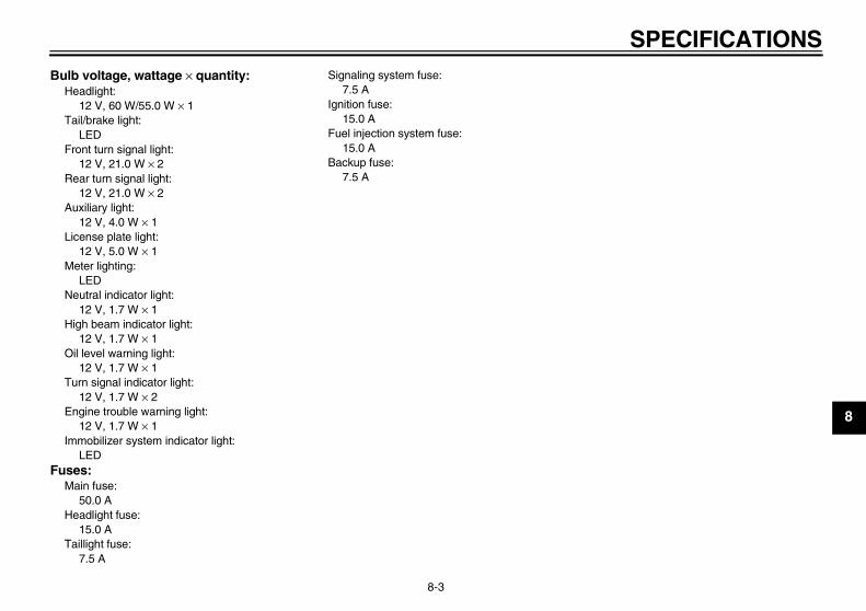
SPECIFICATIONS
8-3
8
Bulb voltage, wattage × quantity:Headlight:
12 V, 60 W/55.0 W × 1Tail/brake light:
LEDFront turn signal light:
12 V, 21.0 W × 2Rear turn signal light:
12 V, 21.0 W × 2Auxiliary light:
12 V, 4.0 W × 1License plate light:
12 V, 5.0 W × 1Meter lighting:
LEDNeutral indicator light:
12 V, 1.7 W × 1High beam indicator light:
12 V, 1.7 W × 1Oil level warning light:
12 V, 1.7 W × 1Turn signal indicator light:
12 V, 1.7 W × 2Engine trouble warning light:
12 V, 1.7 W × 1Immobilizer system indicator light:
LEDFuses:
Main fuse:50.0 A
Headlight fuse:15.0 A
Taillight fuse:7.5 A
Signaling system fuse:7.5 A
Ignition fuse:15.0 A
Fuel injection system fuse:15.0 A
Backup fuse:7.5 A
U5WME5E0.book Page 3 Wednesday, December 5, 2007 10:30 AM
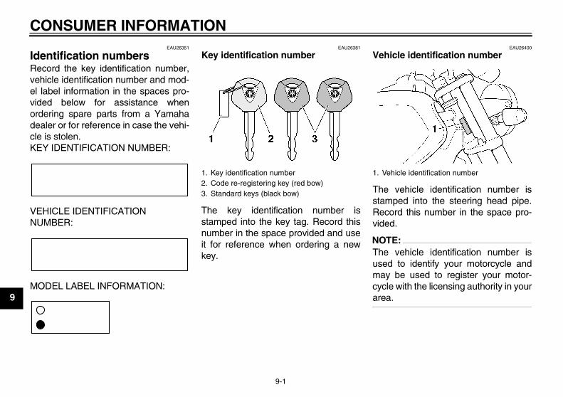
CONSUMER INFORMATION
9-1
9
EAU26351
Identification numbers Record the key identification number,vehicle identification number and mod-el label information in the spaces pro-vided below for assistance whenordering spare parts from a Yamahadealer or for reference in case the vehi-cle is stolen.KEY IDENTIFICATION NUMBER:
VEHICLE IDENTIFICATION NUMBER:
MODEL LABEL INFORMATION:
EAU26381
Key identification number
The key identification number isstamped into the key tag. Record thisnumber in the space provided and useit for reference when ordering a newkey.
EAU26400
Vehicle identification number
The vehicle identification number isstamped into the steering head pipe.Record this number in the space pro-vided.
NOTE:The vehicle identification number isused to identify your motorcycle andmay be used to register your motor-cycle with the licensing authority in yourarea.
1. Key identification number2. Code re-registering key (red bow)3. Standard keys (black bow)
1. Vehicle identification number
U5WME5E0.book Page 1 Wednesday, December 5, 2007 10:30 AM
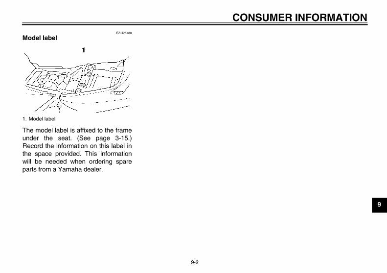
CONSUMER INFORMATION
9-2
9
EAU26480
Model label
The model label is affixed to the frameunder the seat. (See page 3-15.)Record the information on this label inthe space provided. This informationwill be needed when ordering spareparts from a Yamaha dealer.
1. Model label
U5WME5E0.book Page 2 Wednesday, December 5, 2007 10:30 AM
INDEXA
Air filter element and check hose, replacing and cleaning........................ 6-11
Anti-theft alarm (optional)........................ 3-9Auxiliary light bulb, replacing ................ 6-31
BBattery................................................... 6-26Brake and clutch fluid levels,
checking ............................................. 6-18Brake and clutch fluids, changing ......... 6-19Brake and clutch levers, checking and
lubricating ........................................... 6-23Brake and shift pedals, checking and
lubricating ........................................... 6-22Brake lever............................................ 3-11Brake pedal........................................... 3-12
CCables, checking and lubricating .......... 6-21Care ........................................................ 7-1Catalytic converters .............................. 3-14Centerstand and sidestand, checking
and lubricating .................................... 6-23Clutch lever ..................................3-10, 6-16
DDimmer switch ........................................ 3-9Drive chain, cleaning and lubricating .... 6-21Drive chain slack................................... 6-19
EEngine break-in....................................... 5-3Engine oil and oil filter element ............... 6-8Engine stop switch ................................ 3-10Engine trouble warning light.................... 3-4EXUP system........................................ 3-21
FFront and rear brake pads, checking.... 6-17Front fork, adjusting.............................. 3-16Front fork, checking .............................. 6-24Fuel....................................................... 3-13Fuel consumption, tips for reducing........ 5-3Fuel tank breather hose........................ 3-14Fuel tank cap ........................................ 3-12Fuses, replacing ................................... 6-27
HHandlebar switches ................................ 3-9Hazard switch ....................................... 3-10Headlight bulb, replacing ...................... 6-28Helmet holder ....................................... 3-15High beam indicator light ........................ 3-4Horn switch........................................... 3-10
IIdentification numbers ............................ 9-1Ignition circuit cut-off system ................ 3-22Immobilizer system................................. 3-1Immobilizer system indicator light........... 3-4Indicator and warning lights.................... 3-4
KKey identification number ....................... 9-1
LLicense plate light bulb, replacing ........ 6-31Luggage strap holders.......................... 3-20
MMain switch/steering lock........................ 3-2Matte color, caution ................................ 7-1Model label ............................................. 9-2Multi-function display .............................. 3-6
NNeutral indicator light.............................. 3-4
OOil level warning light ..............................3-4
PPanels, removing and installing ..............6-6Parking ....................................................5-4Part locations ..........................................2-1Pass switch .............................................3-9Periodic maintenance and lubrication
chart......................................................6-2Pre-operation check list...........................4-2
RRear brake light switch, adjusting .........6-16
SSafety information ...................................1-1Seat.......................................................3-15Shifting ....................................................5-2Shift pedal .............................................3-11Shock absorber assemblies,
adjusting .............................................3-18Sidestand ..............................................3-21Spark plugs, checking .............................6-7Specifications ..........................................8-1Speedometer...........................................3-5Starting the engine ..................................5-1Start switch............................................3-10Steering, checking.................................6-25Storage....................................................7-3Storage compartment............................3-16Swingarm pivots, lubricating .................6-24
TTachometer .............................................3-5Tail/brake light.......................................6-30Throttle cable free play, checking .........6-12
U5WME5E0.book Page 1 Wednesday, December 5, 2007 10:30 AM
INDEXThrottle grip and cable, checking and
lubricating ........................................... 6-22Tires...................................................... 6-13Tool kit .................................................... 6-1Troubleshooting.................................... 6-35Troubleshooting chart ........................... 6-36Turn signal indicator lights...................... 3-4Turn signal light bulb, replacing............ 6-30Turn signal switch................................... 3-9
VValve clearance .................................... 6-13Vehicle identification number.................. 9-1
WWheel bearings, checking .................... 6-26Wheel (front) ......................................... 6-32Wheel (rear).......................................... 6-33Wheels.................................................. 6-16
U5WME5E0.book Page 2 Wednesday, December 5, 2007 10:30 AM

A5-yoko_Blank.fm Page 1 Tuesday, April 8, 2003 11:43 AM

A5-yoko_Blank.fm Page 1 Tuesday, April 8, 2003 11:43 AM

PRINTED ON RECYCLED PAPER YAMAHA MOTOR CO., LTD.
PRINTED IN JAPAN2008.01-0.3×1 CR
(E)


![Porgetto Maltese - Uwish Furniture - Agencia Comercial CORTO MALTESE.pdf · &dsrgfrshud ghvljq froohfwlrq ghvljq pdqxhod shol]]rq vloydqr slhugrqde &ruwr 0dowhvh +xjr 3udww &rqj 6d](https://img.pdfslide.us/doc/110x75/5c688dab09d3f290788ba727/porgetto-maltese-uwish-furniture-agencia-corto-maltesepdf-dsrgfrshud-ghvljq.jpg)


![XJR1300(P) - XJR Owners of Sweden1].pdf · MICHELIN/DUNLOP MICHELIN/DUNLOP ... Bypass 1 (B.P.1) Bypass 2 (B.P.2) Bypass 3 (B.P.3) Pilot screw (P.S) ... 18 Guide wire 19 Fuel tank](https://img.pdfslide.us/doc/110x75/5af602387f8b9a190c8f17a8/xjr1300p-xjr-owners-of-1pdfmichelindunlop-michelindunlop-bypass-1-bp1.jpg)


![,Q 6HDUFK RI +XJR &K£YH] $XWKRU V 0LFKDHO 6KLIWHU …sites.middlebury.edu/modernlatinamericaspring2012/files/2010/02/In... · have been used to deny Chavez's opponents jobs and services](https://img.pdfslide.us/doc/110x75/5e187e312b73535f4a4b6ddb/q-6hdufk-ri-xjr-kyh-xwkru-v-0lfkdho-6kliwhu-sites-have-been-used-to.jpg)