Embed Size (px)
Citation preview
XFabric: A Reconfigurable In-Rack Network for Rack-Scale Computers
Sergey LegtchenkoMicrosoft Research
Nicholas ChenMicrosoft Research
Daniel CletheroeMicrosoft Research
Antony RowstronMicrosoft Research
Hugh WilliamsMicrosoft Research
Xiaohan Zhao∗
Microsoft Research
AbstractRack-scale computers are dense clusters with hundredsof micro-servers per rack. Designed for data centerworkloads, they can have significant power, cost and per-formance benefits over current racks. The rack networkcan be distributed, with small packet switches embed-ded on each processor as part of a system-on-chip (SoC)design. Ingress/egress traffic is forwarded by SoCs thathave direct uplinks to the data center. Such fabrics arenot fully provisioned and the chosen topology and uplinkplacement impacts performance for different workloads.
XFabric is a rack-scale network that reconfigures thetopology and uplink placement using a circuit-switchedphysical layer over which SoCs perform packet switch-ing. To satisfy tight power and space requirements in therack, XFabric does not use a single large circuit switch,instead relying on a set of independent smaller circuitswitches. This introduces partial reconfigurability, assome ports in the rack cannot be connected by a cir-cuit. XFabric optimizes the physical topology and man-ages uplinks, efficiently coping with partial reconfigura-bility. It significantly outperforms static topologies andhas a performance similar to fully reconfigurable fabrics.We demonstrate the benefits of XFabric using flow-basedsimulations and a prototype built with electrical cross-point switch ASICs.
1 Introduction
There is a trend in large-scale data centers towards higherper-rack server density. While a typical compute rack to-day is composed of 40 to 50 blade servers interconnectedthrough a Top of Rack (ToR) switch, hardware ven-dors increasingly propose energy-efficient, high densitymicro-servers, designed for data center workloads [17,27, 35]. Rack-scale computers, such as AMD SeaMi-cro [44], HP Moonshot [1] and Boston Viridis [8] are up∗ while on internship from UCSB.
to rack-scale high density clusters of micro-servers withtight integration of the network, storage and compute.For example, the Boston Viridis supports hundreds ofSoCs in one standard data center rack. Rack-scale com-puters are optimized for commodity data center work-loads and have significant power, cost and performancebenefits over traditional racks [4, 21, 22, 38] and attractincreasing research interest [5, 6, 14, 16, 39, 42].
Higher server density requires a redesign of the in-racknetwork. A fully provisioned 40 Gbps network with 300SoCs would require a ToR switch with 12 Tbps of bisec-tion bandwidth within a rack enclosure which imposespower, cooling and physical space constraints. For ex-ample, the peak power draw (for power, compute, stor-age and networking) is limited by the power distributionused in data centers and the amount of heat that the in-rack cooling is able to dissipate and is around 9-16 kWfor a typical high density rack today [3]. To address thesechallenges, some proposed designs replace a ToR switchby a “distributed fabric” where the packets forwarding isdone by the servers. If the system uses SoCs then a smallpacket switch can be embedded on the server’s SoC. Forexample, Boston Viridis uses the Calxeda EnergyCoreSoC which has an embedded packet switch supportingeight 10 Gbps lanes. Each SoC is connected to a subsetof SoCs in the rack, forming a multi-hop, bounded de-gree topology, e.g. mesh or torus. Each SoC forwardsin-rack traffic from other SoCs and ingress/egress trafficis tunneled through a set of SoCs that have direct uplinksto the data center network.
Distributed fabrics are cost effective, but lack the flex-ibility of a fully provisioned network. Bisection band-width and end-to-end latency in the rack are a functionof the network topology, and the best topology dependson the expected workload. Ingress/egress traffic is for-warded through multiple hops in the rack to an uplink,interfering with in-rack traffic. Lack of flexibility leadsto suboptimal performance and complicates the design.For example, the HP Moonshot has three independent
1
networks with different topologies within the same en-closure: a radial fabric for ingress/egress traffic, andmulti-hop storage and 2D torus fabrics for in-rack traffic.
XFabric is a rack-scale network that maintains thebenefits of a distributed fabric but allows workload-specific reconfigurability of the topology and uplinks.XFabric is organized as a packet-switched network run-ning over a physical circuit-switched network that allowsthe physical topology of the fabric to be dynamically re-configured. This could be achieved by using a singlelarge circuit switch that would provide full reconfigura-bility, so any two SoC ports in the rack can be directlyconnected. However, XFabric needs to operate withinthe space and power limitations of the rack.
To achieve this, XFabric uses partial reconfigurabil-ity. It partitions the physical layer into a set of smallerindependent circuit switches such that each SoC has aport attached to each partition. Packets can be routedbetween the partitions by the packet switches embeddedin the SoCs. The partitioning significantly reduces thecircuit switch port requirements enabling a single cross-point switch ASIC to be used per partition. This makesXFabric deployable in a rack at reasonable cost.
However, the challenge is that the fabric is no longerfully reconfigurable, as SoC ports attached to differentcrosspoint switch ASICs cannot be connected directly.XFabric uses a novel topology generation algorithm thatis optimized to generate a topology and determine whichcircuits should be established per partition. It also gen-erates the appropriate forwarding tables for each SoCpacket switch. The algorithm is efficient, and XFabriccan instantiate topologies frequently, e.g. every secondat a scale of hundreds of SoCs, if required. Additionally,it is able to place uplinks to the data center enabling themto be efficiently reconfigured.
XFabric uses insights from extensive work on re-configurable data center-scale networks that enable dy-namically reconfigurable network links between ToRswitches [13, 20, 23, 24, 41, 47]. Similar to prior work,e.g. OSA [13] and FireFly [24], the topology is recon-figured at the physical layer, and network traffic is for-warded through multiple hops over the reconfigurabletopology. XFabric differs in that it has been designedto operate at a rack-scale with SoCs that have embeddedpacket switches with multiple ports. It neither relies onwireless technology that cannot be used in the rack, norrequires a single large circuit switch. Designed for cost-effective in-rack deployments, XFabric sacrifices full re-configurability for partial reconfigurability and demon-strates that this still provides good performance.
We have a prototype cluster, which uses 27 servers em-ulating SoCs and an XFabric network built with custom32-port switches using low cost commodity crosspointswitch ASICs. We evaluate XFabric using this prototype
and a flow-based simulator at larger scale. The resultsshow that under realistic workload assumptions, the per-formance of XFabric is up to six times better than a static3D-Torus topology at rack scale. We also show it pro-vides comparable performance to a fully reconfigurablenetwork while consuming five times less power.
The rest of the paper is organized as follows. Sec. 2motivates our design and Sec. 3 provides an overviewof XFabric. Sec. 4 details the algorithms used by thecontroller. Sec. 5 describes our current implementationof XFabric. Sec. 6 evaluates the performance of XFabric.Finally, Sec. 7 and 8 present related work and conclude.
2 Partial Reconfigurability
Reconfigurable networks have been traditionally pro-posed at data center scale [13,20,23,24,41,47]. In thesenetworks, each ToR has d reconfigurable ports and theset of d ToRs to which each ToR is directly connected isdynamically adapted to match the traffic demand. Thishas been implemented either with wireless (e.g. RF-based or free-space optics) [23, 24] or Optical CircuitSwitches (OCS) [13, 20, 41, 47]. In the latter case, alld ports of all the n ToRs are connected to the same OCSthat acts as a circuit switch with n× d ports: any portcan be connected to any port of any ToR and the networktopology is fully reconfigurable.
XFabric is focused on providing reconfigurability atthe rack-scale, which has unique challenges because ofthe additional constraints due to physical space, powerand cooling limitations. At the densities that can po-tentially be achieved using SoCs, the number of ports ishigh. If the switch functionality is distributed across theSoCs and a distributed network fabric is used, the num-ber of ports required will be even higher. For example,a fully reconfigurable distributed fabric with 256 SoCsand 6 ports per SoC for in-rack communication requires1,536 ports. This port count is too high to use a sin-gle crosspoint switch ASIC. It is possible to build a cir-cuit switch implemented as a folded Clos network withmultiple crosspoint switches, however, a folded Clos tosupport n× d ports requires 5× n× d ports to be provi-sioned [13], which, for this example setup would require5×256×6 = 7,680 ports.
Fitting this in the rack can be challenging, but pow-ering and cooling it will be hard. The per-port powerdraw ranges from 0.14 W for a typical optical circuitswitch [11] to 0.28 W for a 10 Gbps electrical circuitswitch [12]. The switches would consume between 1.3to 2.6 kW, representing a significant fraction of the powerprovisioned for a high density rack today [3]. Given thatas we increase density the compute and storage power re-quirements will also increase we need to manage power
2
Controller
Generatetopology
RackSoC S1
SoC S2
Uplinksto
data centerChassis
Controlplane
Estimatedemand
ConfigureData plane
Uplink crosspoint
Internalcrosspoint
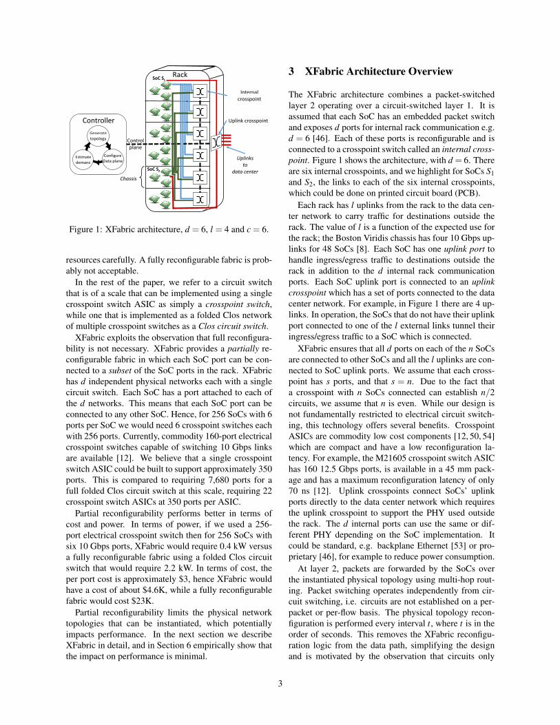
Figure 1: XFabric architecture, d = 6, l = 4 and c = 6.
resources carefully. A fully reconfigurable fabric is prob-ably not acceptable.
In the rest of the paper, we refer to a circuit switchthat is of a scale that can be implemented using a singlecrosspoint switch ASIC as simply a crosspoint switch,while one that is implemented as a folded Clos networkof multiple crosspoint switches as a Clos circuit switch.
XFabric exploits the observation that full reconfigura-bility is not necessary. XFabric provides a partially re-configurable fabric in which each SoC port can be con-nected to a subset of the SoC ports in the rack. XFabrichas d independent physical networks each with a singlecircuit switch. Each SoC has a port attached to each ofthe d networks. This means that each SoC port can beconnected to any other SoC. Hence, for 256 SoCs with 6ports per SoC we would need 6 crosspoint switches eachwith 256 ports. Currently, commodity 160-port electricalcrosspoint switches capable of switching 10 Gbps linksare available [12]. We believe that a single crosspointswitch ASIC could be built to support approximately 350ports. This is compared to requiring 7,680 ports for afull folded Clos circuit switch at this scale, requiring 22crosspoint switch ASICs at 350 ports per ASIC.
Partial reconfigurability performs better in terms ofcost and power. In terms of power, if we used a 256-port electrical crosspoint switch then for 256 SoCs withsix 10 Gbps ports, XFabric would require 0.4 kW versusa fully reconfigurable fabric using a folded Clos circuitswitch that would require 2.2 kW. In terms of cost, theper port cost is approximately $3, hence XFabric wouldhave a cost of about $4.6K, while a fully reconfigurablefabric would cost $23K.
Partial reconfigurability limits the physical networktopologies that can be instantiated, which potentiallyimpacts performance. In the next section we describeXFabric in detail, and in Section 6 empirically show thatthe impact on performance is minimal.
3 XFabric Architecture Overview
The XFabric architecture combines a packet-switchedlayer 2 operating over a circuit-switched layer 1. It isassumed that each SoC has an embedded packet switchand exposes d ports for internal rack communication e.g.d = 6 [46]. Each of these ports is reconfigurable and isconnected to a crosspoint switch called an internal cross-point. Figure 1 shows the architecture, with d = 6. Thereare six internal crosspoints, and we highlight for SoCs S1and S2, the links to each of the six internal crosspoints,which could be done on printed circuit board (PCB).
Each rack has l uplinks from the rack to the data cen-ter network to carry traffic for destinations outside therack. The value of l is a function of the expected use forthe rack; the Boston Viridis chassis has four 10 Gbps up-links for 48 SoCs [8]. Each SoC has one uplink port tohandle ingress/egress traffic to destinations outside therack in addition to the d internal rack communicationports. Each SoC uplink port is connected to an uplinkcrosspoint which has a set of ports connected to the datacenter network. For example, in Figure 1 there are 4 up-links. In operation, the SoCs that do not have their uplinkport connected to one of the l external links tunnel theiringress/egress traffic to a SoC which is connected.
XFabric ensures that all d ports on each of the n SoCsare connected to other SoCs and all the l uplinks are con-nected to SoC uplink ports. We assume that each cross-point has s ports, and that s = n. Due to the fact thata crosspoint with n SoCs connected can establish n/2circuits, we assume that n is even. While our design isnot fundamentally restricted to electrical circuit switch-ing, this technology offers several benefits. CrosspointASICs are commodity low cost components [12, 50, 54]which are compact and have a low reconfiguration la-tency. For example, the M21605 crosspoint switch ASIChas 160 12.5 Gbps ports, is available in a 45 mm pack-age and has a maximum reconfiguration latency of only70 ns [12]. Uplink crosspoints connect SoCs’ uplinkports directly to the data center network which requiresthe uplink crosspoint to support the PHY used outsidethe rack. The d internal ports can use the same or dif-ferent PHY depending on the SoC implementation. Itcould be standard, e.g. backplane Ethernet [53] or pro-prietary [46], for example to reduce power consumption.
At layer 2, packets are forwarded by the SoCs overthe instantiated physical topology using multi-hop rout-ing. Packet switching operates independently from cir-cuit switching, i.e. circuits are not established on a per-packet or per-flow basis. The physical topology recon-figuration is performed every interval t, where t is in theorder of seconds. This removes the XFabric reconfigu-ration logic from the data path, simplifying the designand is motivated by the observation that circuits only
3
need to be reconfigured when the workload traffic patternchanges sufficiently to make reconfiguration beneficial.Layer 2 packet switching over layer 1 circuit switchingforms the data plane of XFabric.
XFabric is managed by an in-rack controller that re-ceives from each SoC estimates of its traffic demand toother SoCs and the uplink. Figure 1 shows the work-flow of the controller. Periodically, it aggregates the in-formation received from the SoCs into a rack-scale de-mand matrix and computes a new topology optimized forthe demand. It then instantiates the topology in the dataplane by establishing new circuits at the physical layerand updates the layer 2 forwarding tables. We assumethat the packet switches on the SoCs support function-ality to allow them to program their forwarding tables,e.g. OpenFlow [40]. The topology generation algorithmis lightweight and operates within the limitations im-posed by the partially reconfigurable fabric, only produc-ing topologies that can be instantiated by the network.
The SoC on which the controller executes needs tobe connected to a micro-controller associated with eachcrosspoint ASIC through a control plane shown in dottedlines in Figure 1. Our current prototype supports Ether-net and USB control planes and we assume that a smallfraction (e.g. 3) have their uplink ports connected to thisnetwork rather than an uplink crosspoint. The controlleris designed to use only soft state and the reconfigurationprocess is resilient to the failure of the controller. If thecontroller fails then the network will be left in a consis-tent state and the controller can be started on another SoCwhich is connected to the control plane.
4 XFabric Configuration
XFabric needs to determine the mapping of the uplinks toSoCs and the internal fabric topology. The uplink map-ping is performed first, because ingress/egress traffic in-duces load on the internal fabric while routed to the SoCswith external uplinks. Before describing the uplink map-ping and internal topology generation algorithms, we de-scribe how XFabric estimates the traffic demand.
4.1 Traffic Demand EstimationFor internal traffic, each SoC maintains a vector of lengthn and records the total number of bytes sent to each SoCin the rack. For external traffic, the SoC maintains twovalues, Ti and Te, the total number of bytes sent and re-ceived, respectively. Periodically, this information is sentto the controller through the data plane and the countersare reset, and we call these demand vectors.
The controller maintains two vectors vi and ve of sizen for ingress/egress traffic in which vi[S] is the numberof bytes sent and ve[S] the number of bytes received by
S during the interval. The controller aggregates the de-mand vectors into an n× n demand matrix, dm, suchthat dm[S1,S2] represents a demand weight from S1 toS2, maintained using a weighted average.
4.2 Uplink Configuration AlgorithmThe uplink configuration selects l SoCs that will be di-rectly connected to the data center network and to whichother SoCs need to tunnel their external traffic.
Conceptually, the controller partitions the n SoCs inthe rack into l sets and places an uplink on one of theSoCs in each set. This SoC acts as a gateway to the datacenter network for the rest of the SoCs in the set. Thecontroller aims to balance traffic between uplinks usingthe demand vectors vi and ve. Ideally, the aggregate ex-ternal traffic demand is the same across all sets and foreach set, the uplink is placed on the SoC with heaviestexternal traffic demand.
The placement algorithm operates in two stages. First,for each of the l uplinks, it selects the SoC S that hasthe highest demand Dext [S] = vi[S]+ ve[S] and no uplinkand places the uplink on S. In the second stage, the al-gorithm determines the sets of SoCs associated to eachuplink. This is done by ordering SoCs without uplinksby their Dext and iteratively assigning the SoC with high-est demand to the set with the least aggregate demand.Ordering SoCs by demand ensures that SoCs with highdemand will be fairly balanced across sets. Once all theSoCs have been assigned, source and destination SoCsfor all external traffic are known. Based on this knowl-edge, the algorithm builds a traffic matrix dmu in whichdmu[S1,S2] is the ingress (and dmu[S2,S1] the egress)traffic demand between a SoC S1 and its uplink placed onS2. The algorithm then creates a matrix dmall which is asum of dmext and dm. This matrix is used by the topologygeneration algorithm to optimize the in-rack topology toboth internal and external traffic.
4.3 Topology Generation AlgorithmThis phase computes a topology optimized for dmall byreducing the hop count between SoCs with high demand.
Forwarding high bandwidth traffic through multiplehops consumes bandwidth per link and incurs load oneach SoC packet switch it traverses. Lower hop countthus results in lower link load and less resources spenton forwarding, improving network goodput [13]. For la-tency sensitive traffic, such as in-memory storage usingRDMA [18], reducing the round trip time is important.A one hop latency of 1 microsecond versus a four hoplatency of 4 microseconds is significant.
Conceptually, for each pair of SoCs in the rack, the al-gorithm assigns a weight based on their relative demand.
4
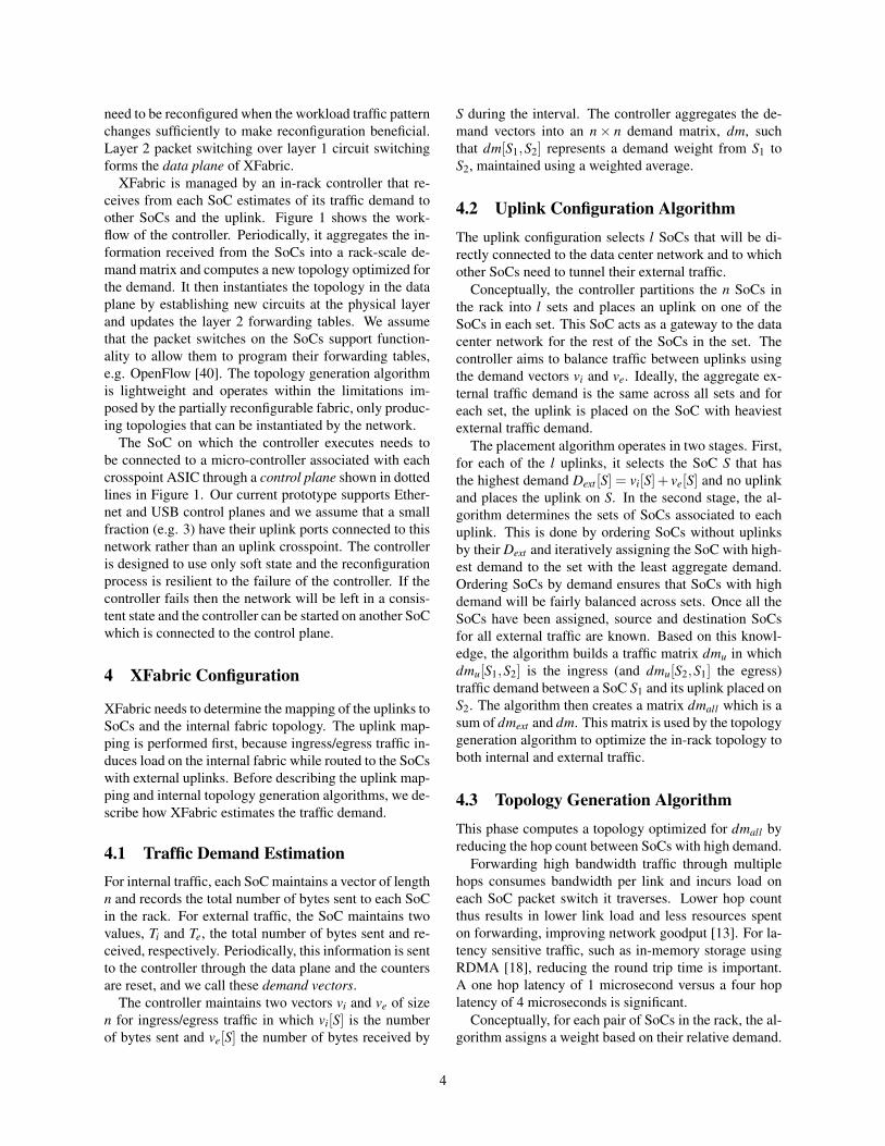
Input:socs← SoC list[n]dmall ← demand matrixport map← XbarToSoCPortMapping[c]
Output:PacketForwardingTablesCircuitAssignment circuits[c]
1 topo← Disconnected Topology(socs)2 SoC pairs← Order By Demand(socs,dmall)3 xbar map← To Xbar(SoC pairs, port map)4 while SoC pairs 6=∅ do5 partition count← 06 foreach soc in socs do7 part[soc] = {soc}8 partition count← partition count +19 foreach pair in SoC pairs do
10 if part[pair.src] 6= part[pair.dest] then11 xbars← xbar map[pair]12 xbar← Best Ranked(xbars,SoC pairs)13 xbars[xbar].Add Circuit({pair.src, pair.dest})14 topo.Add Undirected Edge(pair.src, pair.dest)15 Merge(part[pair.src], part[pair.dest])16 partition count = partition count−117 foreach p in SoC pairs do18 if xbar map.Con f lict(p, pair,xbar) then19 xbar map[p].Remove(xbar)20 if xbar map[p] =∅ then21 xbar map.Remove(p)22 SoC pairs.Remove(p)23 else if p = pair then24 SoC pairs.Reinsert(p, p.demand)25 if partition count = 1 then26 break27 return {topo.ComputeForwardingTables(), circuits}Algorithm 1: XFabric topology generation algorithm.
It then iteratively computes disjoint maximum weightspanning trees until all SoC ports in the rack have beenassigned. The resulting topology is a union of maximumweight spanning trees and has three key properties. First,by construction it is fully connected, i.e., there exists apath between each pair of SoCs. Second, it maximizesresource usage as all ports are assigned. Finally, as span-ning trees are of maximum weight, SoC pairs with heavytraffic demand are satisfied in priority. A key challenge isto support partial reconfigurability and to do this withinthe constraints imposed by the physical topology.
Algorithm 1 describes the process in detail. The al-gorithm inputs are a list of SoCs and crosspoint portsto which each is attached (socs and port map, whichare initialized at boot time) and the demand matrixdmall . It starts by initializing three data structures: topo,SoC pairs and xbar map (lines 1 to 3). The first is afully disconnected topology in which each SoC in therack is represented by a vertex and to which edges will begreedily added. We define the demand between a pair ofSoCs {S1,S2} as D{S1,S2} = dmall [S1][S2]+dmall [S2][S1]and SoC pairs is a list of all pairs of SoCs that can beconnected through each crosspoint, ordered by their de-mands in descending order (highest first). The last is a
dictionary that associates each pair of SoCs to a set ofcrosspoints through which they can be connected. Ini-tially, each pair of SoCs can be connected through any ofthe d crosspoints.
The main loop (lines 4 to 26) performs a sequence ofspanning tree computations and stops when no more SoCpairs can be connected (line 4). The maximum weightcomputation is based on Kruskal’s algorithm [32]: itstarts with a set of partitions, one for each SoC (lines 5 to8), and greedily reduces the number of partitions by con-necting the two SoCs that are not in the same partitionand have the highest demand (line 10). This results intwo partitions being merged as their SoCs are no longerdisconnected (lines 15-16). If only one partition remains,all SoCs are connected by a maximum weight spanningtree (line 25-26).
In order to connect a pair of SoCs, the algorithm se-lects one of the crosspoints through which the connec-tion can be made (lines 11-12). Crossbar ports cannotbe reused for multiple circuits simultaneously, thereforeconnecting a pair of SoCs {S1, S2} through a crosspointC implies that S1 or S2 can no longer be connected toother SoCs through C. It means that establishing a circuitin C negatively impacts its ability to satisfy remaining de-mand. In order to select a crosspoint in which connectingS1 to S2 has the least negative impact, a ranking betweenthe crosspoints is performed (line 12). The ranking func-tion computes the aggregate demand of all connectionsbetween S1, S2 to any other SoC that has a free port inC. This represents the demand that C would not be ableto satisfy if {S1, S2} was established, hence the cross-point with the lowest value is selected. At that point,both the pair of SoCs and the crosspoint have been deter-mined and the corresponding undirected edge and circuitare added (lines 13-14). Finally, the algorithm updatesSoC pairs and xbar map (lines 17 to 24). It removesC from all the pairs in xbar map that can no longer beconnected through C (line 18-19). If the SoC pair canno longer be connected through any of the crosspoints,it is removed from SoC pairs (lines 21 to 22). As twoSoCs can be connected through multiple crosspoints atthe same time, the pair that has just been connected isnot removed from the SoC pairs but reinserted after thelast pair that has some unsatisfied demand (line 24). Thatway, if all pairs with demand have been connected, thealgorithm can add secondary direct connections betweenhigh demand pairs, increasing the bandwidth.
The algorithm executes in polynomial time and onceall circuits have been assigned, the topology is optimizedfor dmall . The algorithm has the property that in additionto computing an optimized topology, it also finds the cir-cuit assignment that instantiates that topology in the par-tially reconfigurable fabric. The result of the algorithmis a set of forwarding tables derived from the computed
5
topology and the circuit assignment that is merged withthe uplink circuit assignment. The controller uses thisinformation to reconfigure the data plane.
4.4 Reconfiguration
To instantiate a new topology, the XFabric controllerneeds to update the circuit switches (layer 1) and ensureall forwarding tables in each SoC are updated (layer 2).This cannot be achieved instantaneously, and can lead toinstability during the update interval. The goal of recon-figuration is to minimize this window of instability.
We considered two general approaches. Inspired bySWAN [25], we experimented with incrementally chang-ing the physical topology to ensure that packets can besuccessfully routed. This requires identifying a set of in-termediate topologies, and then moving traffic off linksthat are to be reconfigured and then stepping throughmultiple different intermediate configurations. This ap-proach leads to larger reconfiguration periods: the timetaken to reconfigure is approximately constant and in-dependent of the number of links being reconfigured,so migrating through x intermediate topologies takes xtimes the reconfiguration delay. Hence, we adopted theapproach of performing a single reconfiguration.
Before triggering the reconfiguration, the controllersends new circuit assignments to every circuit switchthrough the control plane and new forwarding state to theSoCs through the data plane. Each circuit switch receivesa map packet composed of a list of port mappings and abitmap to indicate which ports need to be reconfigured.The micro-controller on the switch loads the circuit as-signments into a set of registers on the crosspoint ASICand acknowledges the controller, but does not instanti-ate the circuits. The physical topology must remain un-changed at this stage as the controller has no out-of-bandmechanism to communicate with the SoCs. Each SoC re-ceives its new forwarding tables together with the MACaddress of the SoC that will be connected to each of itsports and a unique 64-bit version number for the config-uration. This is efficiently encoded so the forwarding ta-ble, plus all the other information for a XFabric with 512SoCs is less than 1 KB. Each SoC runs a process thatreceives and stores the update, but again does not repro-gram any forwarding tables. Once all the SoCs have ac-knowledged the update information, all circuit switchesand SoCs are ready for the reconfiguration.
The controller triggers the reconfiguration by trans-mitting a reconfigure packet to each circuit switchthrough the control plane. When received, the micro-controller on the circuit switch reprograms its crosspointASIC to the configuration specified in the map. At thispoint the physical network (layer 1) has been reconfig-ured, but the forwarding tables at the SoCs have not yet
been updated. Once every circuit switch has acknowl-edged, the controller uses a simple flood-based mech-anism to trigger the use of the new forwarding tableson each SoC. It sends on each of its ports a reconfig-uration message which includes the new configurationversion number. If a SoC with an old forwarding tablereceives the reconfiguration message, it starts using thenew one and issues a reconfiguration message on all itsports. SoCs with new forwarding tables ignore reconfig-uration messages. This process ensures rapid reconfigu-ration, in the worst case the number of rounds will be thediameter of the network.
It is essential that the data plane rapidly converges toa consistent state, even if the controller fails during theprocess. In particular, if the failure occurs after sendingout a reconfigure to a subset of the circuit switches,the physical topology could be left in an inconsistentstate. To address this, we ensure that each circuit switchthat receives a reconfigure and has not yet reconfig-ured broadcasts the message through the control plane.
A failure of the controller before the broadcast of thereconfiguration in the data plane could lead to stale for-warding state at layer 2. To avoid this, we allow theSoCs to locally trigger the update of the forwarding ta-bles. It does this by monitoring the local MAC addressesof SoCs attached to its ports: if a packet is received froma different MAC address than expected the SoC flushesthe current forwarding table and uses the new one. Afterthis local update, the SoC broadcasts a reconfigurationmessage, ensuring that the new forwarding state is prop-agated despite the failure of the controller.
During the reconfiguration of the switches any packetsin flight at the switch can be corrupted or lost. However,thanks to the low switching latency of electrical cross-point ASICs (see Section 3), we observe the packet lossto be low in practice (see Section 6) and rely on end-to-end transport protocols to recover from the packet loss.
5 XFabric Implementation
We have built a prototype XFabric platform, consist-ing of a set of seven electrical circuit switch units and27 servers, each configured with eight 1 Gbps EthernetNICs and a single Intel Xeon E5520 8-core 2.27GHzCPU running Windows Server 2008 R2 Enterprise. Eachserver emulates a SoC with an embedded packet switchthat has six NIC ports for in-rack traffic. One NIC port isused as an uplink port and the last port is connected to aToR switch for debug and experiment control.
Each circuit switch unit has 32 ports and each server isconnected to all 7 circuit switches. Six serve as internalcrosspoints and the last one is an uplink crosspoint withfour uplinks (l = 4). The switches use the Analog De-vices ADN4605 asynchronous fully non-blocking cross-
6
point switch ASIC [51]. Currently, they are connectedto the servers using standard Ethernet cables, hence weneed transceivers to convert the signal to and from theASIC to 1000Base-T which is supported by the servers.This has significant cost and power overhead implica-tions and is due to using standard servers instead of SoCsin the prototype platform. Each crosspoint ASIC is man-aged by an ARM Cortex-M3 micro-controller that con-figures it via an SPI serial bus and transceivers throughI2C. The current design does not support 10 Gbps links,but we are in the process of designing a version with160 10 Gbps ports using the Macom M21605 crosspointASIC [12]. In the experiments we use USB 1.1 to com-municate with the control plane due to lack of spareEthernet ports per server. Ethernet is supported by ourswitches and improves control plane latency by about anorder of magnitude compared to USB.
The packet switch emulation is done in software,which allows us to understand the full functionality re-quired before implementing it in hardware. The emulatoruses two kernel drivers and a user-level process, and im-plements an OpenFlow-like API that provides access tothe forwarding table, and callbacks on certain conditions.It binds to the six NIC ports used for internal traffic andthe port used for the uplink. It also provides a virtualizedNIC, to which an unmodified TCP/IP stack is bound toallow unmodified applications to be run on the testbed.
6 Evaluation
In this section we evaluate XFabric. First, we comparethe performance of a reconfigurable fabric to static phys-ical topologies. Then, we evaluate the efficiency of thealgorithms used in XFabric. Finally, we show the bene-fits and overheads of XFabric dynamic reconfiguration.
In the experiments we evaluate XFabric using the pro-totype described in Section 5. In order to allow us toevaluate XFabric at scale we also use a simple flow-basedsimulator. We start by describing the fabric topologies,workloads and metrics used during the evaluation.
6.1 TopologiesWe compare against three different topologies, two staticand one dynamic. The first static topology is a 3DTorus (3DTorus). This topology has been widely used inHPC [15, 48] and has been proposed in data centers [2],in particular at rack scale [44]. It has the highest pathlength and lowest bisection bandwidth, but has a highdisjoint path diversity and low cabling complexity.
The second one is a static random topology (Random).Random topologies have also been proposed for use indata centers [45] and are known to be “expander” graphswith high bisection bandwidth and low diameter.
We also use a dynamic reconfigurable network (OSA)inspired by OSA. In this network the topology is config-ured using the topology generation algorithm proposedin [13]. Our goal is to compare against the topology gen-eration algorithm and we do not simulate additional fea-tures, such as the flexible link capacity described in [13].Our implementation of the algorithm uses the same graphlibrary as OSA [33]. This network uses a Clos circuitswitch to which all the internal ports of all the SoCs areconnected, so it is fully reconfigurable.
For the simulation results, unless otherwise stated, weassume the rack contains 343 SoCs each with d = 6 in-ternal ports per SoC and one uplink port. In all cases weassume that the number of ports for the internal cross-points is s = n and for the uplink crosspoint s = n+ l. Weassume there are six internal crosspoints (as d = 6), andone uplink crosspoint with l = 8. Unless otherwise statedthe uplinks are uniformly distributed across the SoCs andeach SoC sends ingress/egress traffic to its nearest uplinkin terms of path length.
We use 343 SoCs as it allows us to compare against a3D Torus of size 73 = 343. This is a challenge for XFab-ric, as a crosspoint with n ports establishes n/2 circuitsso, if n is odd, one port cannot be connected to any otherport on the same crosspoint. So, we will end up with 6unused ports across all the SoCs. In practice, XFabricuses an even number of SoCs to avoid this issue. To han-dle the odd n configurations we form three pairs of cross-points and in each pair statically connect a random SoCof one crosspoint to a different SoC in the second cross-point. This means these static circuits are never reconfig-ured and results in strictly worse performance comparedto allowing them to be reconfigured.
6.2 Workloads
We selected two workloads with well-identified trafficpatterns, both based on real-world measurements.Production cluster workload. This is a trace of 339servers running a production workload in a mid-sizedenterprise data center [7]. The data was collected overa period of 6.8 days and contains per-TCP-flow infor-mation including the source and destination IP address,the number of bytes transferred and a mapping from theservers’ hostnames to the IP addresses of their NICs. Wegroup flows based on source and destination hostnames.Flows in which the source or destination IP address doesnot correspond to a known hostname are considered asuplink traffic. The traffic is clustered, with heavy com-munication between servers with common hostname pre-fixes, and many-to-one traffic patterns: servers with acommon hostname prefix often exchange traffic with aspecific server with a different hostname prefix. This isconsistent with the patterns described in [30].
7
0
1
2
3
4
5
6
Production LiveJournal
3DTorus
Random
XFabric
OSA
Pat
h le
ngt
h(#
ho
ps) Lower is
better
(a) Path length
0
0.5
1
1.5
2
2.5
3
Production LiveJournal
3DTorus
Random
XFabric
OSA
Pat
h d
iver
sity
(#d
isjo
int
pat
hs)
Higher isbetter
(b) Average path diversity
0.1
1
10
100
Production LiveJournal
3DTorus
Random
XFabric
OSA
% o
f to
tal f
low
s
Lower isbetter
(c) Bottleneck link load
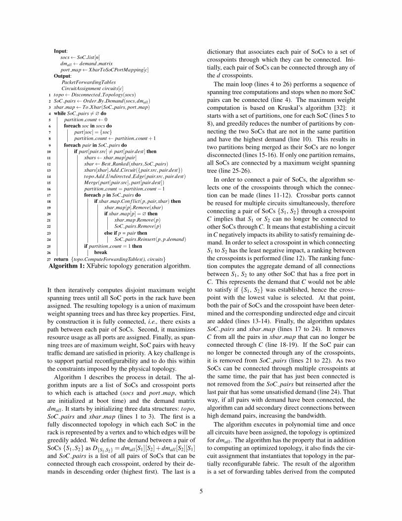
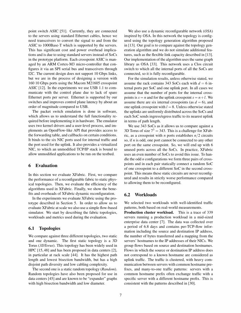
Figure 2: Performance summary of different fabrics for Production and LiveJournal workloads.
LiveJournal. Distributed platforms such as Pregel [34]or Tao [9] enable efficient processing of large graphs bypartitioning the graph across a set of SoCs such that eachSoC is assigned a set of vertices from the original graph.To generate a graph processing workload we use a tracecollected from LiveJournal in December 2006 [36]. It in-cludes 95.4% of users at that time, representing 5.2 mil-lion nodes and 48.7 million edges with an average edgedegree of 18.7 edges per node. We shard the verticesinto partitions using METIS, an offline graph partition-ing algorithm [31] to uniformly partition the graph whileminimizing traffic between partitions. There is one parti-tion per SoC and we assume that the computation makesprogress by message passing along the edges of the par-titioned graph. The traffic is proportional to the numberof the social graph edges between SoCs and is modeledas a constant bit rate over time.
For both workloads we map the workload onto theSoCs randomly. We also explored topology-aware work-load placement using heuristic-based approaches for thestatic topologies [10]. For these we found that topology-aware placement always performs better than the ran-dom placement, but was always worse than the topol-ogy generated by XFabric. In practice, topology-awareplacement is not easily feasible, and would often re-quire migrating data between servers and is challengingto achieve dynamically. Due to lack of space, we onlypresent results for random placement.
In the simulations each workload is mapped into a sin-gle traffic matrix tm such that for each pair of SoCs itstores the number of bytes sent and received betweenthese SoCs. For the production trace, to scale beyond339 SoCs, we augment the original trace by duplicatinga random set of SoCs with non-zero traffic. For experi-ments with less than 339 SoCs, we subsample the traceby taking a random subset of the SoCs that have traffic.
6.3 Metrics
Across the experiments we use a number of metrics:Path length. For each packet, we measure the pathlength from source to destination in number of hops.
Fabric # ports Cost Power drawClos Circuit Switch 10,290 $30.9K 2.9 kWXFabric 2,058 $6.2K 0.6 kW
Table 1: Estimated cost & power, 343 SoCs, 6 ports/SoC.
Since each hop adds a delay while forwarding traffic, thismetric is a proxy for end-to-end latency.Path diversity. This metric accounts for the fault tol-erance of the topology, it measures the number of dis-joint shortest paths that exist for each packet. Two pathsare disjoint if they share no common link. Therefore, ifthere are k shortest paths for all the flows in the topol-ogy, k− 1 links can fail without impacting the averagepath length of the traffic. Route diversity also improvestraffic load balancing allowing traffic to be spread acrossdisjoint shortest paths.Bottleneck link load. The metric measures the conges-tion within the topology by measuring the link load onthe most congested link in the topology.
6.4 XFabric Performance
The two static topologies, 3D Torus and Random, do notrequire any additional hardware other than the switchingfunctionality provided in the SoCs. Both the OSA andXFabric require additional ASICs to enable the recon-figurability. Any benefit obtained from being reconfig-urable needs to be offset against the increased overheadsthis induces. Table 1 shows the number of ports requiredand the estimated cost and power consumption for XFab-ric and OSA assuming $3 per port and 0.28 W per portfor 343 SoCs. OSA is a fully reconfigurable fabric sup-porting 2,058 ports, thus using a folded Clos. XFabric re-quires d crosspoint ASICs with n ports, connecting eachSoC to each of the d crosspoints. This has a significantbenefit in terms of cost and power.
This first simulation experiment evaluates the relativeperformance of the four topologies using the two work-loads. For each configurable fabric we take the globaldemand matrix tm and optimize the network for tm. Fig-
8
0
1
2
3
4
5
6
2 8 32 128
Path
len
gth
(#h
op
s)
Skew (cluster size)
OSA XFabric
3D Torus Random
(a) Clustered workload
0
1
2
3
4
5
6
2 4 8 16 32 64 128 256
OSA XFabric
3D Torus Random
Skew (#random destinations/SoC)
Pat
h le
ngt
h (
#ho
ps)
(b) Random destinations workload
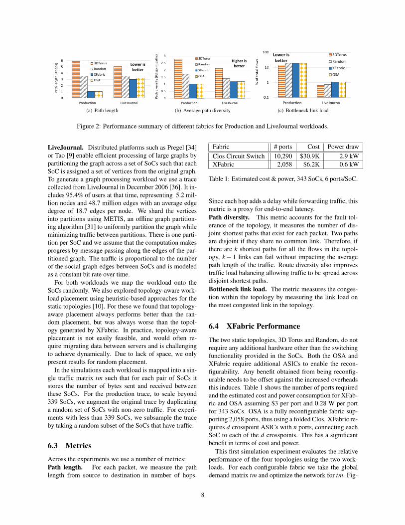
Figure 3: Impact of traffic skew on path length
ure 2(a) shows the average path length achieved by allthe fabrics. Across both workloads the reconfigurablefabrics, XFabric and OSA, achieve shorter average pathlengths than the static topologies. For Production, XFab-ric has an average path length of only 1.06 hops, which is6 times less than 3D Torus and 3.7 times less than Ran-dom. For the LiveJournal workload, the path length forthe reconfigurable fabrics is also lower but not by such amargin. As we will demonstrate later, the reason is dueto the traffic skew. The LiveJournal workload has a lowerskew. Comparing the performance of OSA and XFabric,we see for the Production workload that they both pro-vide comparable performance. Notably for LiveJournal,even though OSA has a fully reconfigurable fabric it per-forms worse than XFabric. Having more flexibility in thefabric is insufficient, you also need an algorithm that canreconfigure the fabric to exploit the full flexibility.
Figure 2(b) shows the path diversity for all four fab-rics with both workloads. These results show that thereconfigurable fabrics instantiate topologies with lowerpath diversity. The path length reduction benefits beingshown in Figure 2(a) are achieved at the expense of re-ducing path diversity, shorter path lengths offer less op-portunity for forwarding through different links. The 3DTorus has the highest path diversity, but also has the high-est path length. This is an interesting trade-off wherereconfigurability can provide benefit. Lowering path di-versity can impact resilience to failure, and it also lowersthe aggregate bandwidth available on the shortest pathsbetween two SoCs. For reconfigurable fabrics, a link orSoC failure can be overcome by calculating a new topol-ogy that minimizes the impact of the failure. XFabricalso can link multiple ports between the same SoCs, soproviding multiple 1-hop links between two SoCs, and
hence increase the aggregate bandwidth.To understand this further, Figure 2(c) shows the num-
ber of flows that traverse each link. A flow from a to bis routed over the set of shortest paths in the topologybetween a and b and is registered on each link in thepath. To achieve this each flow is split into f subflowsof constant size, where f is much larger than the num-ber of paths. The simulator estimates path congestionby counting the number of flows registered on the mostloaded link in a path. To place a subflow, the simulator’stransport layer checks if multiple shortest paths exist. Ifso two are randomly selected, and the simulator placesthe flow on the least congested one. This simulates trafficrouting though multiple paths for any workload on top ofany topology. Furthermore, the flow routing scheme en-sures a good load balance of the traffic across links [37].Figure 2(c) shows the percentage of flows that traversethe bottleneck link for each workload and topology. Themost congested links on all topologies for both work-loads have approximately the same load, except for the3D Torus that benefits from its high path diversity.
The trade-off between path length and diversity alsoimpacts the total network load across all links. The loadimbalance across links is reduced when path diversity ishigh: in the 3D Torus the load is better balanced acrosslinks due to load balancing across multiple paths. How-ever, because of the higher path length, the overall totalload on links in the network is higher. The other topolo-gies have a lower average total network link load than the3D Torus, but a higher skew. However, XFabric aggres-sively reduces path length without significantly increas-ing load skew because optimization leads to links beingshared across fewer source destination pairs.
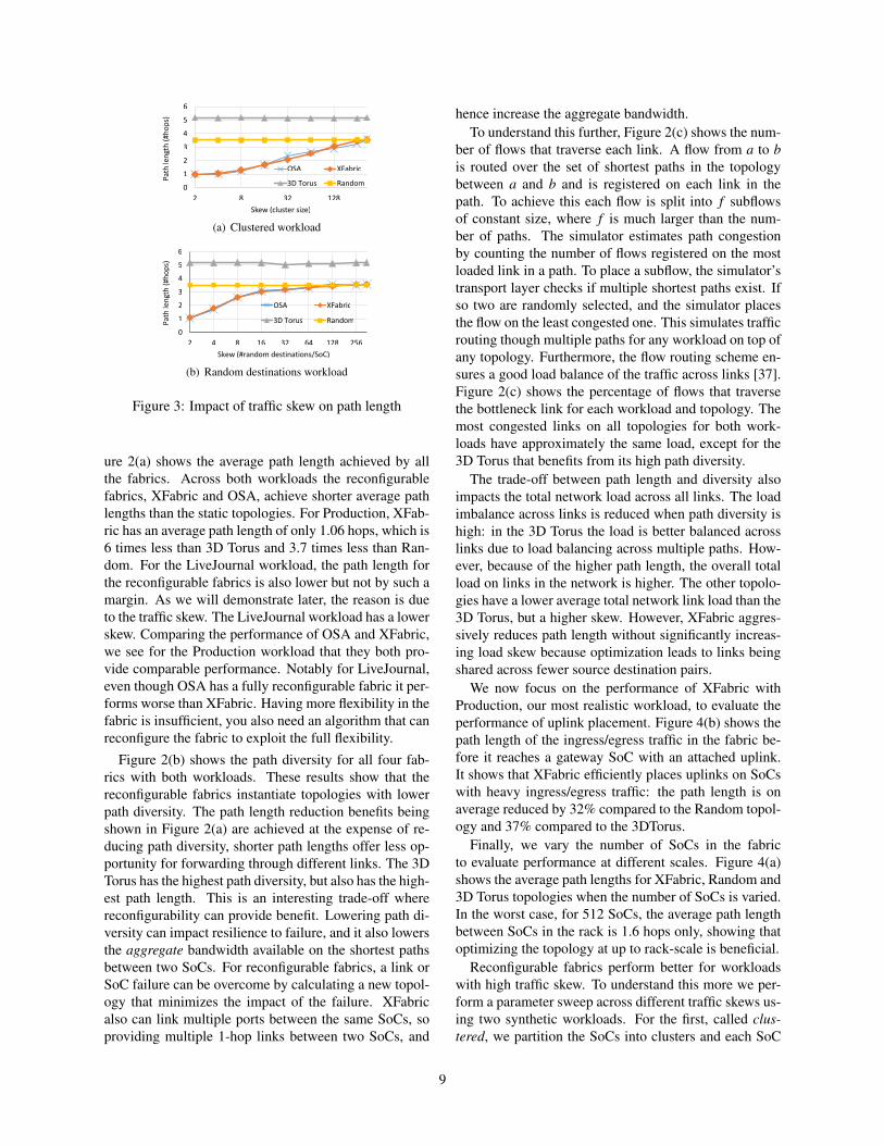
We now focus on the performance of XFabric withProduction, our most realistic workload, to evaluate theperformance of uplink placement. Figure 4(b) shows thepath length of the ingress/egress traffic in the fabric be-fore it reaches a gateway SoC with an attached uplink.It shows that XFabric efficiently places uplinks on SoCswith heavy ingress/egress traffic: the path length is onaverage reduced by 32% compared to the Random topol-ogy and 37% compared to the 3DTorus.
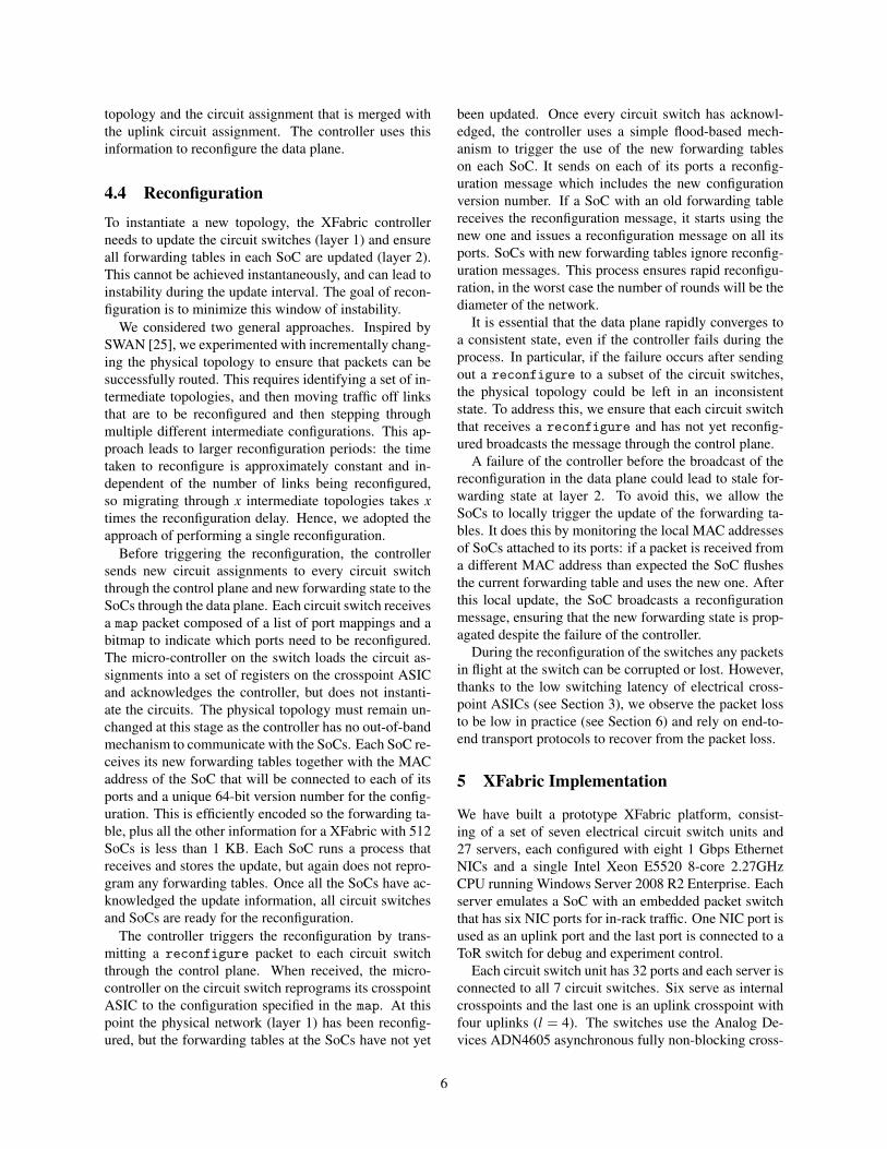
Finally, we vary the number of SoCs in the fabricto evaluate performance at different scales. Figure 4(a)shows the average path lengths for XFabric, Random and3D Torus topologies when the number of SoCs is varied.In the worst case, for 512 SoCs, the average path lengthbetween SoCs in the rack is 1.6 hops only, showing thatoptimizing the topology at up to rack-scale is beneficial.
Reconfigurable fabrics perform better for workloadswith high traffic skew. To understand this more we per-form a parameter sweep across different traffic skews us-ing two synthetic workloads. For the first, called clus-tered, we partition the SoCs into clusters and each SoC
9
0
1
2
3
4
5
6
7
27 64 125 512
XFabric
Random
3DTorus
Fabric size (#SoCs)
Avg
.pat
h le
ngt
h (
#ho
ps)
(a) Path length vs. network size
0
0.5
1
1.5
2
2.5
3
Pat
hle
ngt
h (
#ho
ps)
Random XFabric3DTorus
(b) Uplink placement
Figure 4: Scalability and uplink placement performance.
communicates with all other SoCs in the same cluster.We vary the number of SoCs per cluster between 2 and343. Intuitively, this results in a set of traffic matrices inwhich the traffic skew grows as cluster size drops. Fig-ure 3(a) shows the path length as a function of the clustersize for XFabric and OSA with the clustered workload.The cluster size has no impact on static topologies be-cause no reconfiguration is performed. When the skewis high, reconfigurable topologies are able to more effi-ciently optimize for the skew, up to the point when mostof the traffic is sent through 1 hop. As the cluster sizeincreases, the traffic pattern shifts to an all-to-all patternand performance of reconfigurable fabrics becomes com-parable to a Random topology. Notably, there is almostno difference between XFabric and OSA.
We run a second experiment with a different workloadto evaluate the impact of the traffic pattern on path length.For this workload, called random destinations, each SoCsends traffic to a random set of k SoCs in the rack. Forlow values of k, the workload is very skewed and as itincreases the workload progressively adopts an all-to-alltraffic pattern. However, this results in a less clusteredworkload, even when traffic is very skewed. Figure 3(b)shows the path length as a function of the number of des-tinations per SoC for all fabrics. We observe the sametrend as for the clustered workload, with both OSA andXFabric outperforming static topologies by up to a factorof 3.5 when the skew is high.
6.5 XFabric Prototype Performance
So far we evaluated the benefits of XFabric at scale us-ing our simulator. In the next experiment we use our
prototype platform to evaluate the dynamic reconfigura-tion performance of XFabric. Frequent XFabric recon-figuration is beneficial as it improves the responsivenessof the fabric to changes in traffic load, improving perfor-mance. However, too frequent reconfiguration inducesoverheads at the packet switching layer as it may resultin packet loss. The reconfiguration of the crosspoints atlayer 1 is not synchronized with layer 2. Too frequentpacket loss can have a negative impact on the throughputat the transport layer, particularly if TCP is used.
We have created a test framework that uses unmodifiedTCP and replays flow-level traces derived from the Pro-duction workload. The framework opens a new socketfor each flow and starts six flows per SoC concurrently,operating as a closed loop per SoC, so when one flow fin-ishes the next is started on the SoC. In each experimentwe configure the network as a 3D Torus and do not allowthe network to reconfigure for the first 2 minutes. Unlessotherwise stated the flow size is selected from the distri-bution of flow sizes in the Production workload, whichis a typical heavy tailed distribution with a small numberof elephant flows and a high number of mice flows, andan average flow size of 9.3 MB.
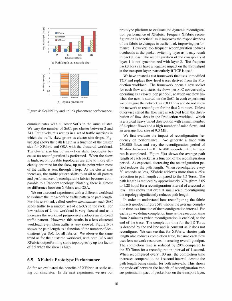
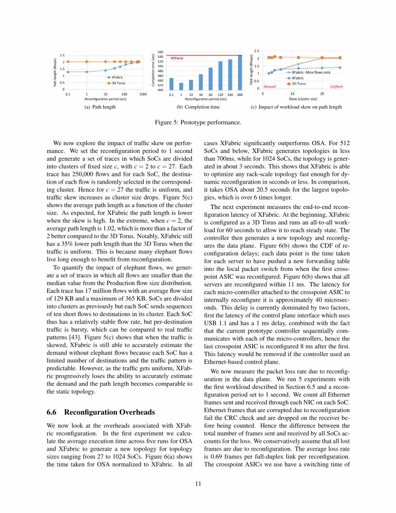
We first evaluate the impact of reconfiguration fre-quency on performance. We generate a trace with250,000 flows and vary the reconfiguration period ofXFabric between t = 0.1 to 480 seconds until the tracerun is completed. Figure 5(a) shows the average pathlength of each packet as a function of the reconfigurationperiod. As expected, decreasing the reconfiguration pe-riod reduces the path length. When reconfigured every30 seconds or less, XFabric achieves more than a 25%reduction in path length compared to the 3D Torus. Thepath length is reduced by approximately 37% (from 2.05to 1.28 hops) for a reconfiguration interval of a second orless. This shows that even at small scale, reconfiguringthe topology significantly reduces path length.
In order to understand how reconfiguring the fabricimpacts goodput, Figure 5(b) shows the average comple-tion time as a function of the reconfiguration interval. Foreach run we define completion time as the execution timefrom 2 minutes (when reconfiguration is enabled) to theend of the trace. The completion time for the 3D Torusis denoted by the red line and is constant as it does notreconfigure. We can see that for XFabric, shorter pathlength also reduces completion time, because each flowuses less network resources, increasing overall goodput.The completion time is reduced by 20% compared tothe 3D Torus for a reconfiguration interval of 1 second.When reconfigured every 100 ms, the completion timeincreases compared to the 1 second interval, despite thepath length being similar for both intervals. This showsthe trade-off between the benefit of reconfiguration ver-sus potential impact of packet loss on the transport layer.
10
0
0.5
1
1.5
2
2.5
0.1 1 10 100 1000
Path
len
gth
(#h
op
s)
Reconfiguration period (sec)
XFabric
3D Torus
(a) Path length
400
420
440
460
480
500
520
540
560
0.1 1 10 30 60 120 240 480Reconfiguration period (sec)
Co
mp
leti
on
tim
e(s
ec)
3DTorus
(b) Completion time
0
0.5
1
1.5
2
2.5
0 10 20
Path
len
gth
(#h
op
s)
Skew (cluster size)
XFabric- Mice flows only
XFabric
3D TorusSkewed Uniform
(c) Impact of workload skew on path length
Figure 5: Prototype performance.
We now explore the impact of traffic skew on perfor-mance. We set the reconfiguration period to 1 secondand generate a set of traces in which SoCs are dividedinto clusters of fixed size c, with c = 2 to c = 27. Eachtrace has 250,000 flows and for each SoC, the destina-tion of each flow is randomly selected in the correspond-ing cluster. Hence for c = 27 the traffic is uniform, andtraffic skew increases as cluster size drops. Figure 5(c)shows the average path length as a function of the clustersize. As expected, for XFabric the path length is lowerwhen the skew is high. In the extreme, when c = 2, theaverage path length is 1.02, which is more than a factor of2 better compared to the 3D Torus. Notably, XFabric stillhas a 35% lower path length than the 3D Torus when thetraffic is uniform. This is because many elephant flowslive long enough to benefit from reconfiguration.
To quantify the impact of elephant flows, we gener-ate a set of traces in which all flows are smaller than themedian value from the Production flow size distribution.Each trace has 17 million flows with an average flow sizeof 129 KB and a maximum of 365 KB. SoCs are dividedinto clusters as previously but each SoC sends sequencesof ten short flows to destinations in its cluster. Each SoCthus has a relatively stable flow rate, but per-destinationtraffic is bursty, which can be compared to real trafficpatterns [43]. Figure 5(c) shows that when the traffic isskewed, XFabric is still able to accurately estimate thedemand without elephant flows because each SoC has alimited number of destinations and the traffic pattern ispredictable. However, as the traffic gets uniform, XFab-ric progressively loses the ability to accurately estimatethe demand and the path length becomes comparable tothe static topology.
6.6 Reconfiguration Overheads
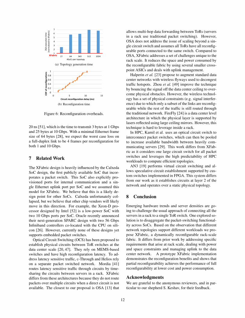
We now look at the overheads associated with XFab-ric reconfiguration. In the first experiment we calcu-late the average execution time across five runs for OSAand XFabric to generate a new topology for topologysizes ranging from 27 to 1024 SoCs. Figure 6(a) showsthe time taken for OSA normalized to XFabric. In all
cases XFabric significantly outperforms OSA. For 512SoCs and below, XFabric generates topologies in lessthan 700ms, while for 1024 SoCs, the topology is gener-ated in about 3 seconds. This shows that XFabric is ableto optimize any rack-scale topology fast enough for dy-namic reconfiguration in seconds or less. In comparison,it takes OSA about 20.5 seconds for the largest topolo-gies, which is over 6 times longer.
The next experiment measures the end-to-end recon-figuration latency of XFabric. At the beginning, XFabricis configured as a 3D Torus and runs an all-to-all work-load for 60 seconds to allow it to reach steady state. Thecontroller then generates a new topology and reconfig-ures the data plane. Figure 6(b) shows the CDF of re-configuration delays; each data point is the time takenfor each server to have pushed a new forwarding tableinto the local packet switch from when the first cross-point ASIC was reconfigured. Figure 6(b) shows that allservers are reconfigured within 11 ms. The latency foreach micro-controller attached to the crosspoint ASIC tointernally reconfigure it is approximately 40 microsec-onds. This delay is currently dominated by two factors,first the latency of the control plane interface which usesUSB 1.1 and has a 1 ms delay, combined with the factthat the current prototype controller sequentially com-municates with each of the micro-controllers, hence thelast crosspoint ASIC is reconfigured 8 ms after the first.This latency would be removed if the controller used anEthernet-based control plane.
We now measure the packet loss rate due to reconfig-uration in the data plane. We run 5 experiments withthe first workload described in Section 6.5 and a recon-figuration period set to 1 second. We count all Ethernetframes sent and received through each NIC on each SoC.Ethernet frames that are corrupted due to reconfigurationfail the CRC check and are dropped on the receiver be-fore being counted. Hence the difference between thetotal number of frames sent and received by all SoCs ac-counts for the loss. We conservatively assume that all lostframes are due to reconfiguration. The average loss rateis 0.69 frames per full-duplex link per reconfiguration.The crosspoint ASICs we use have a switching time of
11
1
2
3
4
5
6
7
10245123436427
OSA
exec
uti
on
tim
e(n
orm
aliz
ed t
o X
Fab
ric)
#SoCs per topology
XFabric
(a) Topology generation time
0
0.2
0.4
0.6
0.8
1
0 5 10 15CD
F o
f re
con
figu
rati
on
s
Circuit reconfiguration delay (ms)
(b) Reconfiguration time
Figure 6: Reconfiguration overheads.
20 ns [51], which is the time to transmit 3 bytes at 1 Gbpsand 25 bytes at 10 Gbps. With a minimal Ethernet framesize of 64 bytes [28], we expect the worst case loss ona full-duplex link to be 4 frames per reconfiguration forboth 1 and 10 Gbps.
7 Related Work
The XFabric design is heavily influenced by the CalxedaSoC design, the first publicly available SoC that incor-porates a packet switch. This SoC also explicitly pro-visioned ports for internal communication and a sin-gle Ethernet uplink port per SoC and we assumed thismodel for XFabric. We believe that this is a likely de-sign point for other SoCs. Calxeda unfortunately col-lapsed, but we believe that other chip vendors will likelymove in this direction. For example, the Xeon-D pro-cessor designed by Intel [52] is a low-power SoC withtwo 10 Gbps ports per SoC. Oracle recently announcedtheir next-generation SPARC design with two 56 GbpsInfiniband controllers co-located with the CPU on sili-con [26]. However, currently none of these designs yetsupports embedded packet switches.
Optical Circuit Switching (OCS) has been proposed toestablish physical circuits between ToR switches at thedata center scale [20, 47]. They rely on MEMS-basedswitches and have high reconfiguration latency. To ad-dress latency sensitive traffic, c-Through and Helios relyon a separate packet switched network. Mordia [41]routes latency sensitive traffic through circuits by time-sharing the circuits between servers in a rack. XFabricdiffers from these architectures because they do not routepackets over multiple circuits when a direct circuit is notavailable. The closest to our proposal is OSA [13] that
allows multi-hop data forwarding between ToRs (serversin a rack use traditional packet switching). However,OSA does not address the issue of scaling beyond a sin-gle circuit switch and assumes all ToRs have all reconfig-urable ports connected to the same switch. Compared toOSA, XFabric addresses a set of challenges unique to therack scale. It reduces the space and power consumed bythe reconfigurable fabric by using several smaller cross-point ASICs and deals with uplink management.
Halperin et al. [23] propose to augment standard datacenter networks with wireless flyways used to decongesttraffic hotspots. Zhou et al. [49] improve the techniqueby bouncing the signal off the data center ceiling to over-come physical obstacles. However, the wireless technol-ogy has a set of physical constraints (e.g. signal interfer-ence) due to which only a subset of the links are reconfig-urable while the rest of the traffic is still routed throughthe traditional network. FireFly [24] is a data center levelarchitecture in which the physical layer is supported bylasers reflected using large ceiling mirrors. However, thistechnique is hard to leverage inside a rack.
In HPC, Kamil et al. uses an optical circuit switch tointerconnect packet switches, which can then be pooledto increase available bandwidth between heavily com-municating servers [29]. This work differs from XFab-ric as it considers one large circuit switch for all packetswitches and leverages the high predictability of HPCworkloads to compute efficient topologies.
AN3 [19] performs virtual circuit switching and al-lows speculative circuit establishment supported by cus-tom switches implemented in FPGA. This system differsfrom our work as it establishes circuits at layer 2 of thenetwork and operates over a static physical topology.
8 Conclusion
Emerging hardware trends and server densities are go-ing to challenge the usual approach of connecting all theservers in a rack to a single ToR switch. One explored so-lution is to disaggregate the packet-switching functional-ity across SoCs. Based on the observation that differentnetwork topologies support different workloads we pro-pose XFabric, a dynamically reconfigurable rack-scalefabric. It differs from prior work by addressing specificrequirements that arise at rack scale, dealing with powerand space constraints and managing uplink to the datacenter network. A prototype XFabric implementationdemonstrates the reconfiguration benefits and shows thatpartial reconfigurability achieves the performance of fullreconfigurability at lower cost and power consumption.
AcknowledgmentsWe are grateful to the anonymous reviewers, and in par-ticular to our shepherd S. Keshav, for their feedback.
12
References
[1] HP Moonshot System: The World’s First Software-Defined Server -Family guide, Jan. 2014.
[2] ABU-LIBDEH, H., COSTA, P., ROWSTRON, A.,O’SHEA, G., AND DONNELLY, A. SymbioticRouting in Future Data Centers. ACM SIGCOMMComputer Communication Review 41, 4 (2011),51–62.
[3] AFCOM. Data center Standards. http://bit.
ly/1KPoZOZ.
[4] Amazon joins other web giants trying to design itsown chips. http://bit.ly/1J5t0fE.
[5] ASANOVIC, K., AND PATTERSON, D. FireBox:A Hardware Building Block for 2020 Warehouse-Scale Computers. In USENIX FAST (2014).
[6] BALAKRISHNAN, S., BLACK, R., DONNELLY,A., ENGLAND, P., GLASS, A., HARPER, D.,LEGTCHENKO, S., OGUS, A., PETERSON, E.,AND ROWSTRON, A. Pelican: A Building Blockfor Exascale Cold Data Storage. In Proceedings ofthe 11th USENIX conference on Operating SystemsDesign and Implementation (2014), USENIX As-sociation, pp. 351–365.
[7] BALLANI, H., JANG, K., KARAGIANNIS, T.,KIM, C., GUNAWARDENA, D., AND O’SHEA,G. Chatty Tenants and the Cloud Network SharingProblem. In Proceedings of the 10th USENIX con-ference on Networked Systems Design and Imple-mentation (2013), USENIX Association, pp. 171–184.
[8] BOSTON. Boston Viridis Data Sheet. http://
download.boston.co.uk/downloads/9/3/2/
932c4ecb-692a-47a9-937d-a94bd0f3df1b/
viridis.pdf.
[9] BRONSON, N., AMSDEN, Z., CABRERA, G.,CHAKKA, P., DIMOV, P., DING, H., FERRIS, J.,GIARDULLO, A., KULKARNI, S., LI, H., ET AL.Tao: Facebooks Distributed Data Store for the So-cial Graph. In USENIX ATC (2013).
[10] BURKARD, R., PARDALOS, P., AND PITSOULIS,L. The Quadratic Assignment Problem. InHandbook of Combinatorial Optimization (1998),Kluwer Academic Publishers, pp. 241–338.
[11] Calient S320 Optical Circuit Switch Datasheet.http://www.calient.net/download/
s320-optical-circuit-switch-datasheet/.
[12] Macom M21605 Crosspoint Switch Specifica-tion. http://www.macom.com/products/
product-detail/M21605/.
[13] CHEN, K., SINGLA, A., SINGH, A., RA-MACHANDRAN, K., XU, L., ZHANG, Y., WEN,X., AND CHEN, Y. OSA: An Optical SwitchingArchitecture for Data Center Networks with Un-precedented Flexibility. IEEE/ACM Transactionson Networking (TON) 22, 2 (2014), 498–511.
[14] COSTA, P., BALLANI, H., RAZAVI, K., ANDKASH, I. R2C2: A Network Stack for Rack-ScaleComputers. In Proceedings of the 2015 ACM Con-ference on Special Interest Group on Data Commu-nication (2015), ACM, pp. 551–564.
[15] CRAY. CRAY XT3 Datasheet. http://
www.craysupercomputers.com/downloads/
CrayXT3/CrayXT3_Datasheet.pdf.
[16] DAGLIS, A., NOVAKOVIC, S., BUGNION, E.,FALSAFI, B., AND GROT, B. Manycore NetworkInterfaces for In-Memory Rack-Scale Computing.In Proceecidings of the 42nd International Sympo-sium in Computer Architecture (2015), no. EPFL-CONF-207612.
[17] Dell PowerEdge c5220 Microserver.http://www.dell.com/us/business/p/
poweredge-c5220/pd.
[18] DRAGOJEVIC, A., NARAYANAN, D., HODSON,O., AND CASTRO, M. FARM: Fast Remote Mem-ory. In Proceedings of the 11th USENIX Confer-ence on Networked Systems Design and Implemen-tation, NSDI (2014), vol. 14.
[19] ERIC CHUNG, ANDREAS NOWATZYK, TOM RODE-HEFFER, CHUCK THACKER, AND FANG YU. AN3:A Low-Cost, Circuit-Switched Datacenter Net-work. Tech. Rep. MSR-TR-2014-35, March 2014.
[20] FARRINGTON, N., PORTER, G., RADHAKRISH-NAN, S., BAZZAZ, H. H., SUBRAMANYA, V.,FAINMAN, Y., PAPEN, G., AND VAHDAT, A. He-lios: a Hybrid Electrical/Optical Switch Architec-ture for Modular Data Centers. ACM SIGCOMMComputer Communication Review 41, 4 (2011),339–350.
[21] Intel, Facebook Collaborate on Future Data CenterRack Technologies. http://intel.ly/MRpOM0.
[22] Google Ramps Up Chip Design. http://ubm.io/1iQooNe.
13
[23] HALPERIN, D., KANDULA, S., PADHYE, J.,BAHL, P., AND WETHERALL, D. AugmentingData Center Networks with Multi-Gigabit WirelessLinks. In ACM SIGCOMM Computer Communica-tion Review (2011), vol. 41, ACM, pp. 38–49.
[24] HAMEDAZIMI, N., QAZI, Z., GUPTA, H.,SEKAR, V., DAS, S. R., LONGTIN, J. P., SHAH,H., AND TANWER, A. FireFly: a ReconfigurableWireless Data Center Fabric using Free-Space Op-tics. In Proceedings of the 2014 ACM conferenceon SIGCOMM (2014), ACM, pp. 319–330.
[25] HONG, C.-Y., KANDULA, S., MAHAJAN, R.,ZHANG, M., GILL, V., NANDURI, M., ANDWATTENHOFER, R. Achieving High Utilizationwith Software-Driven WAN. In ACM SIGCOMMComputer Communication Review (2013), vol. 43,ACM, pp. 15–26.
[26] Oracles Sonoma Processor. http://www.
hotchips.org/archives/2010s/hc27/.
[27] HP ProLiant m800 Server Cartridge. http://
bit.ly/1JxM9Zr.
[28] IEEE. 802.3-2012 IEEE Standard for Ether-net. http://standards.ieee.org/findstds/
standard/802.3-2012.html.
[29] KAMIL, S., PINAR, A., GUNTER, D., LIJEWSKI,M., OLIKER, L., AND SHALF, J. ReconfigurableHybrid Interconnection for Static and Dynamic Sci-entific Applications. In Proceedings of the 4thinternational conference on Computing frontiers(2007), ACM, pp. 183–194.
[30] KANDULA, S., SENGUPTA, S., GREENBERG, A.,PATEL, P., AND CHAIKEN, R. The Nature of DataCenter Traffic: Measurements & Analysis. In Pro-ceedings of the 9th ACM SIGCOMM conferenceon Internet measurement conference (2009), ACM,pp. 202–208.
[31] KARYPIS, G., AND KUMAR, V. Multilevel Algo-rithms for Multi-Constraint Graph Partitioning. InSupercomputing (1998).
[32] KRUSKAL, J. B. On the Shortest Spanning Subtreeof a Graph and the Traveling Salesman Problem.Proceedings of the American Mathematical society7, 1 (1956), 48–50.
[33] LEMON Graph Library. http://lemon.cs.
elte.hu/trac/lemon.
[34] MALEWICZ, G., AUSTERN, M. H., BIK, A. J.,DEHNERT, J. C., HORN, I., LEISER, N., AND
CZAJKOWSKI, G. Pregel: a System for Large-Scale Graph Processing. In SIGMOD (2010).
[35] Microservers Powered by Intel. http:
//www.intel.com/content/www/us/en/
servers/microservers.html.
[36] MISLOVE, A., MARCON, M., GUMMADI, K. P.,DRUSCHEL, P., AND BHATTACHARJEE, B. Mea-surement and Analysis of Online Social Networks.In IMC (2007).
[37] MITZENMACHER, M. The Power of Two Choicesin Randomized Load Balancing. Parallel and Dis-tributed Systems, IEEE Transactions on 12, 10(2001).
[38] How Microsoft Designs its Cloud-Scale Servers.http://bit.ly/1HKCy27.
[39] NOVAKOVIC, S., DAGLIS, A., BUGNION, E.,FALSAFI, B., AND GROT, B. Scale-Out NUMA.ACM SIGARCH Computer Architecture News 42, 1(2014), 3–18.
[40] OpenFlow Specification. http://
archive.openflow.org/documents/
openflow-spec-v1.1.0.pdf.
[41] PORTER, G., STRONG, R. D., FARRINGTON, N.,FORENCICH, A., SUN, P., ROSING, T., FAIN-MAN, Y., PAPEN, G., AND VAHDAT, A. In-tegrating Microsecond Circuit Switching into theData Center. In ACM SIGCOMM 2013 Conference,SIGCOMM’13, Hong Kong, China, August 12-16,2013 (2013), D. M. Chiu, J. Wang, P. Barford, andS. Seshan, Eds., ACM, pp. 447–458.
[42] PUTNAM, A., CAULFIELD, A. M., CHUNG, E. S.,CHIOU, D., CONSTANTINIDES, K., DEMME, J.,ESMAEILZADEH, H., FOWERS, J., GOPAL, G. P.,GRAY, J., ET AL. A Reconfigurable Fabric for Ac-celerating Large-Scale Data Center Services. InComputer Architecture (ISCA), 2014 ACM/IEEE41st International Symposium on (2014), IEEE,pp. 13–24.
[43] ROY, A., ZENG, H., BAGGA, J., PORTER, G.,AND SNOEREN, A. C. Inside the Social Net-work’s (Datacenter) Network. In Proceedings of the2015 ACM Conference on Special Interest Groupon Data Communication (2015), ACM, pp. 123–137.
[44] SEAMICRO, A. AMD SeaMicro SM15000 FabricCompute Systems. http://www.seamicro.com/sm15000.
14
[45] SINGLA, A., HONG, C.-Y., POPA, L., AND GOD-FREY, P. B. Jellyfish: Networking Data CentersRandomly. In NSDI (2012), vol. 12, pp. 17–17.
[46] SUDAN, K., BALAKRISHNAN, S., LIE, S., XU,M., MALLICK, D., LAUTERBACH, G., AND BAL-ASUBRAMONIAN, R. A Novel System Architec-ture for Web-Scale Applications using LightweightCPUs and Virtualized I/O. In High PerformanceComputer Architecture (HPCA2013), 2013 IEEE19th International Symposium on (2013), IEEE,pp. 167–178.
[47] WANG, G., ANDERSEN, D. G., KAMINSKY, M.,PAPAGIANNAKI, K., NG, T., KOZUCH, M., ANDRYAN, M. c-Through: Part-Time Optics in DataCenters. ACM SIGCOMM Computer Communica-tion Review 41, 4 (2011), 327–338.
[48] WWW.HPCRESEARCH.NL. IBM BlueGene P&Q.http://www.hpcresearch.nl/euroben/
Overview/web12/bluegene.php.
[49] ZHOU, X., ZHANG, Z., ZHU, Y., LI, Y., KUMAR,S., VAHDAT, A., ZHAO, B. Y., AND ZHENG, H.Mirror Mirror on the Ceiling: Flexible Wireless
Links for Data Centers. ACM SIGCOMM Com-puter Communication Review 42, 4 (2012), 443–454.
[50] Analog Devices ADN4612. http:
//www.analog.com/media/en/
technical-documentation/data-sheets/
ADN4612.pdf.
[51] Analog Devices ADN4605. http:
//www.analog.com/en/products/
switches-multiplexers/
digital-crosspoint-switches/adn4605.
html.
[52] Intel Xeon Processor D-1500 Family Prod-uct Brief. http://www.intel.com/
content/www/us/en/processors/xeon/
xeon-processor-d-brief.html.
[53] 10GBase-KR FEC Tutorial. http://www.
ieee802.org/802_tutorials/06-July/
10GBASE-KR_FEC_Tutorial_1407.pdf.
[54] Vitesse VSC3144. https://www.vitesse.com/products/product/VSC3144.
15