Embed Size (px)
Citation preview
Eaton Corporation
X-format Communications Protocol (XCP) Specification
Revision C1 - PublicConnectivity Systems GroupLast updated 13-Feb-09
COPYRIGHT 1998-2009
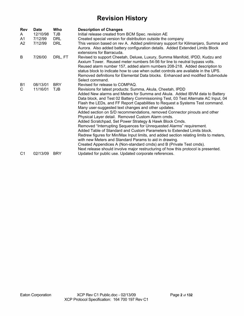
Revision HistoryRev Date Who Description of ChangesA 12/10/98 TJB Initial release created from BCM Spec. revision AEA1 7/12/99 DRL Created special version for distribution outside the companyA2 7/12/99 DRL This version based on rev A. Added preliminary support for Kilimanjaro, Summa and
Aurora. Also added battery configuration details. Added Extended Limits Block extensions for Barracuda.
B 7/26/00 DRL, FT Revised to support Cheetah, Deluxe, Luxury, Summa Manifold, IPDD, Kudzu and Axxium Tower. Reused meter numbers 54-56 for line to neutral bypass volts. Reused alarm number 157, added alarm numbers 208-218. Added description to status block to indicate how to use when outlet controls are available in the UPS. Removed definitions for Elemental Data blocks. Enhanced and modified Submodule Select command.
B1 08/13/01 BRY Revised for release to COMPAQ.C 11/16/01 TJB Revisions for latest products: Summa, Akula, Cheetah, IPDD
Added New alarms and Meters for Summa and Akula. Added IBVM data to Battery Data block, and Test 02 Battery Commissioning Test, 03 Test Alternate AC Input, 04 Flash the LEDs, and FF Report Capabilities to Request a Systems Test command. Many user-suggested text changes and other updates.Added section on S/D recommendations, removed Connector pinouts and other Physical Layer detail. Removed Custom Alarm cmds.Added Scratchpad, Set Power Strategy & Hawk Block Cmds. Removed “Interrupting Sequences for Unrequested Alarms” requirement.Added Table of Standard and Custom Parameters to Extended Limits block.Redrew figures for Min/Max Input limits, and added section relating limits to meters, with new Meters and Standard Params to aid in drawing.Created Appendices A (Non-standard cmds) and B (Private Test cmds).Next release should involve major restructuring of how this protocol is presented.
C1 02/13/09 BRY Updated for public use. Updated corporate references.
Eaton Corporation XCP Rev C1 Public.doc - 02/13/09 Page 2 of 132 XCP Protocol Specification: 164 700 197 Rev C1
Table of Contents1 Introduction...............................................................................................................................................6
1.1 History of Powerware communication protocols......................................................................................... 6
1.2 Goal of this document..................................................................................................................................... 6
1.3 Scope of this standard.................................................................................................................................... 6
1.4 Other documents............................................................................................................................................. 7
2 Hardware Requirements .......................................................................................................................... 83 Protocol Transport specifications.............................................................................................................9
3.1 Performance and timing ................................................................................................................................ 9
3.2 Direct serial connections.............................................................................................................................. 103.2.1 Direct Serial Basics....................................................................................................................................................... 103.2.2 Direct Serial Command Format.................................................................................................................................... 103.2.3 Direct Serial Response Format......................................................................................................................................10
3.3 Modem-based serial connections: ASCII Computer Mode (ACM).......................................................... 123.3.1 Modem Serial Basics ....................................................................................................................................................123.3.2 Modem Serial Command and Response Format...........................................................................................................12
3.4 Byte Ordering............................................................................................................................................... 12
3.5 Data and Map Formats................................................................................................................................ 133.5.1 Date Format for Meters................................................................................................................................................. 143.5.2 Time Format for Meters................................................................................................................................................ 14
4 Operational Requirements......................................................................................................................154.1 UPS Discovery .............................................................................................................................................. 15
4.1.1 Discovery with MS Plug-n-Play ...................................................................................................................................154.1.2 Discovery with Baud Hunting ......................................................................................................................................16
4.2 Identification and Capabilities of the UPS ................................................................................................. 17
4.3 Authorization of Commands........................................................................................................................ 184.3.1 Standard Authorization Block....................................................................................................................................... 184.3.2 Password Authorization................................................................................................................................................ 18
4.4 Response to Commands................................................................................................................................ 194.4.1 Command Acknowledge Block.....................................................................................................................................194.4.2 Commands with No Responses.....................................................................................................................................20
4.5 Unrequested Data Output............................................................................................................................ 21
4.6 Compatibility with User Terminal and Printer modes.............................................................................. 21
4.7 Plain-text Service Commands...................................................................................................................... 23
5 Standard Data blocks.............................................................................................................................. 245.1 UPS Capabilities .......................................................................................................................................... 24
5.1.1 Command List Block ....................................................................................................................................................245.1.2 Communication Capabilities Block...............................................................................................................................25
Eaton Corporation XCP Rev C1 Public.doc - 02/13/09 Page 3 of 132 XCP Protocol Specification: 164 700 197 Rev C1
5.1.3 Communication Port List Block....................................................................................................................................265.1.4 Setting to Requested and Unrequested Modes.............................................................................................................. 28
5.2 Identification and Configuration ................................................................................................................ 295.2.1 Standard ID Block Request........................................................................................................................................... 29
5.2.1.1 Meters Map for Standard ID Block........................................................................................................................325.2.1.2 Alarm Map for Standard ID Block.........................................................................................................................365.2.1.3 Statistics Map for Standard ID Block.....................................................................................................................47
5.2.2 Config Block Request................................................................................................................................................... 505.2.2.1 BYTES 00 - 01 Machine Type Code.................................................................................................................... 515.2.2.2 BYTES 22 - 27 Battery Data ..............................................................................................................................535.2.2.3 BYTES 30-33 Communications Setup..................................................................................................................54
5.2.3 Extended Limits Block Request.................................................................................................................................... 565.2.3.1 Bypass Deviation and Line Regulation Voltages:..................................................................................................595.2.3.2 BYTES 31- Table of Standard and Custom Parameters....................................................................................... 61
5.2.4 Request Scratchpad Data...............................................................................................................................................625.2.5 UPS Topology Data Block............................................................................................................................................ 63
5.3 Meters............................................................................................................................................................ 655.3.1 Standard Meters Block Request.................................................................................................................................... 65
5.4 Alarms and Events........................................................................................................................................ 665.4.1 Action Levels................................................................................................................................................................ 665.4.2 Mapping Action Levels to Trap/Pager Levels:............................................................................................................. 685.4.3 “Well-Known” Traps:................................................................................................................................................... 695.4.4 Active Alarms Data Block............................................................................................................................................ 705.4.5 Alarm / Event History Log Data Block .......................................................................................................................71
5.5 UPS Status .................................................................................................................................................... 735.5.1 Standard UPS Status Data Block...................................................................................................................................735.5.2 Outlet Monitoring Block............................................................................................................................................... 77
5.6 Utility Statistics Data block.......................................................................................................................... 79
5.7 Battery data block........................................................................................................................................ 80
5.8 Test Results Data Block................................................................................................................................ 83
6 Control and Configuration Commands................................................................................................. 846.1 Load Control Commands............................................................................................................................. 84
6.1.1 Delayed Load Power Off & Restart Command.............................................................................................................856.1.2 Scheduled UPS On / Off in "n" Minutes ...................................................................................................................... 876.1.3 Schedule UPS On / Off at Date & Time ...................................................................................................................... 886.1.4 UPS On / Off Commands..............................................................................................................................................896.1.5 Set Outlet Parameter .....................................................................................................................................................906.1.6 Go To Bypass Command.............................................................................................................................................. 91
6.2 UPS Test Commands.................................................................................................................................... 926.2.1 Initiate Battery Test ...................................................................................................................................................... 926.2.2 Request Systems Test Command.................................................................................................................................. 93
6.3 Configuration Change Commands.............................................................................................................. 956.3.1 Set Config Parameter ....................................................................................................................................................956.3.2 Set Communication Parameter......................................................................................................................................976.3.3 Set Time & Date Command ......................................................................................................................................... 986.3.4 Exit XCP Mode Commands.......................................................................................................................................... 996.3.5 Set Scratchpad Sector..................................................................................................................................................1006.3.6 Set Power Strategy Command.....................................................................................................................................101
6.4 Select Sub-module Command for Addressing Multiple Modules........................................................... 104
6.5 Update Power Source Status Command................................................................................................... 106
Eaton Corporation XCP Rev C1 Public.doc - 02/13/09 Page 4 of 132 XCP Protocol Specification: 164 700 197 Rev C1
7 Implementation Details.........................................................................................................................1087.1 Mandatory requirements for UPS implementers..................................................................................... 108
7.2 Using XCP Data to Draw Meter Limits.................................................................................................... 1097.2.1 Input Volts...................................................................................................................................................................1097.2.2 Output Volts................................................................................................................................................................ 1117.2.3 Input and Output Current............................................................................................................................................ 1117.2.4 Load and Power Meters...............................................................................................................................................1127.2.5 Frequency Meters........................................................................................................................................................ 1137.2.6 Battery Meters............................................................................................................................................................. 1147.2.7 Ambient Temperature Meter....................................................................................................................................... 1157.2.8 “Don’t Display Graphically” Meters...........................................................................................................................116
7.3 Notes to Communication Software Developers........................................................................................ 1177.3.1 Powerware UPS Compliances.....................................................................................................................................1177.3.2 Parsing Data Blocks.................................................................................................................................................... 1177.3.3 Deriving Output Meters...............................................................................................................................................1177.3.4 XCP Changes with UPS Revisions............................................................................................................................. 1177.3.5 Testing of Communication Software.......................................................................................................................... 1177.3.6 Provision for Future Additions in UPS Implementation............................................................................................. 1177.3.7 When to initiate Normal and Panic OS Shutdown...................................................................................................... 118
7.3.7.1 Shutdown Recommendations for Software Developers.......................................................................................1187.3.7.2 Shutdown Support Requirements for UPS Developers........................................................................................118
7.4 Considerations for OEMs and foreign languages..................................................................................... 118
7.5 Process for revising this Protocol............................................................................................................... 118
7.6 Specific Applications of this Protocol........................................................................................................ 1197.6.1 Outlet Control..............................................................................................................................................................119
7.6.1.1 Affected Data blocks............................................................................................................................................ 1207.6.1.2 Addressing Individual Outlets..............................................................................................................................120
8 Appendix A: Non-Standard Commands...............................................................................................1218.1 Waveform data........................................................................................................................................... 121
8.2 Hawk Data Block........................................................................................................................................ 1238.2.1 Hawk Function 1: Mimic Data Response...................................................................................................................1238.2.2 Hawk Function 2: Battery Log Entry Response.........................................................................................................1258.2.3 Hawk Function 3: History Log Entry Response........................................................................................................ 128
8.3 Conditional Delayed Load Power Off & Restart ..................................................................................... 129
8.4 Increment / Decrement Output Voltage ................................................................................................... 129
9 Appendix B: Command Summary........................................................................................................131
Eaton Corporation XCP Rev C1 Public.doc - 02/13/09 Page 5 of 132 XCP Protocol Specification: 164 700 197 Rev C1
1 Introduction1.1 History of Powerware communication protocols
In 1997, after the acquisition of IPM and Deltec/FPS, Powerware Corporation (formerly, Exide Electronics) was in a position where the corporation’s UPS products were actively employing 4 different protocols:
• Binary Computer Mode (BCM) was used, at various revision levels, in the Powerware Prestige, Plus 6-36, Plus 80-500, and Series 6000/7000 UPS lines. The oldest implementation, for the AST 5, was begun in 1987. The Plus 6-36 and Series 6000/7000 also implemented Ascii Computer Mode (ACM) for modem transfer.
• FPS and Deltec UPSs used UPScode II in all their products having serial communication. This protocol was first used in 19__.
• Deltec added a binary extension to UPScode II, mainly for load shedding control. This was first used in the PowerRite Max series in 1996.
• The IPM products used “P” records for serial communication, starting in 1991; this protocol was similar to Motorola S-records.
• The Best Products UPSs used a variety of similar protocols, which were unified under the Best Power Common Protocol (BPCP) driver.
By 1997, there was a widespread recognition that Powerware needed to offer UPS, adapter, and software products that correctly interoperate with each other. It was determined that one of the keys to this was to develop one standard for communication to and from all Powerware UPSs. This document describes that protocol, which has survived into UPS products designed and built with the Eaton Corporation name on them.
1.2 Goal of this document
“To describe a standard serial communications protocol for Powerware-branded UPSs from Eaton Corporation and its subsidiaries”
1.3 Scope of this standard
This standard covers the following areas:
Protocol Transport This standard specifies:
• the details of Binary and ASCII communication packets: headers, length specifiers, and checksums
• minimum/maximum response timing for all communications• specify the protocol to be used for modem connections
Operation This standard specifies:
• reliable, standard means for discovering the UPS and learning its capabilities• mechanism for validating control commands• response to all commands• details of an unrequested data mode• compatibility with Microsoft Plug-n-Play• interaction with user or printer terminal modes
Data blocks This standard specifies:
_______________________________________________________________________________________Eaton Corporation XCP Rev C1 Public.doc – 02/13/09 Page 6 of 132 XCP Protocol Specification: 164 700 197 Rev C1
• standard blocks for identification, configuration, meters, status, alarms, events, history, statistics, battery,
• UPS topology, and alarm action levels• non-standard blocks for waveform or parallel configuration data extensions.
Control and Configuration Commands This standard specifies:
• commands for turning the UPS or outlets On and Off, with delays• commands for setting other UPS modes• commands for setting configuration parameters• means of directing commands for multiple modules• Some, but only some, of the complex behaviors for On / Off control are addressed here; other
aspects are addressed in other UPS behavior documents.
Implementation Details This standard specifies:
• which requirements must be implemented in UPSs• means of customizing messages for OEMs and foreign languages• guides for UPS and software developers
This Serial Communications Specification will not address features or requirements of • Hardware requirements are now addressed in a separate document• Communication Software• the protocol used for network packets
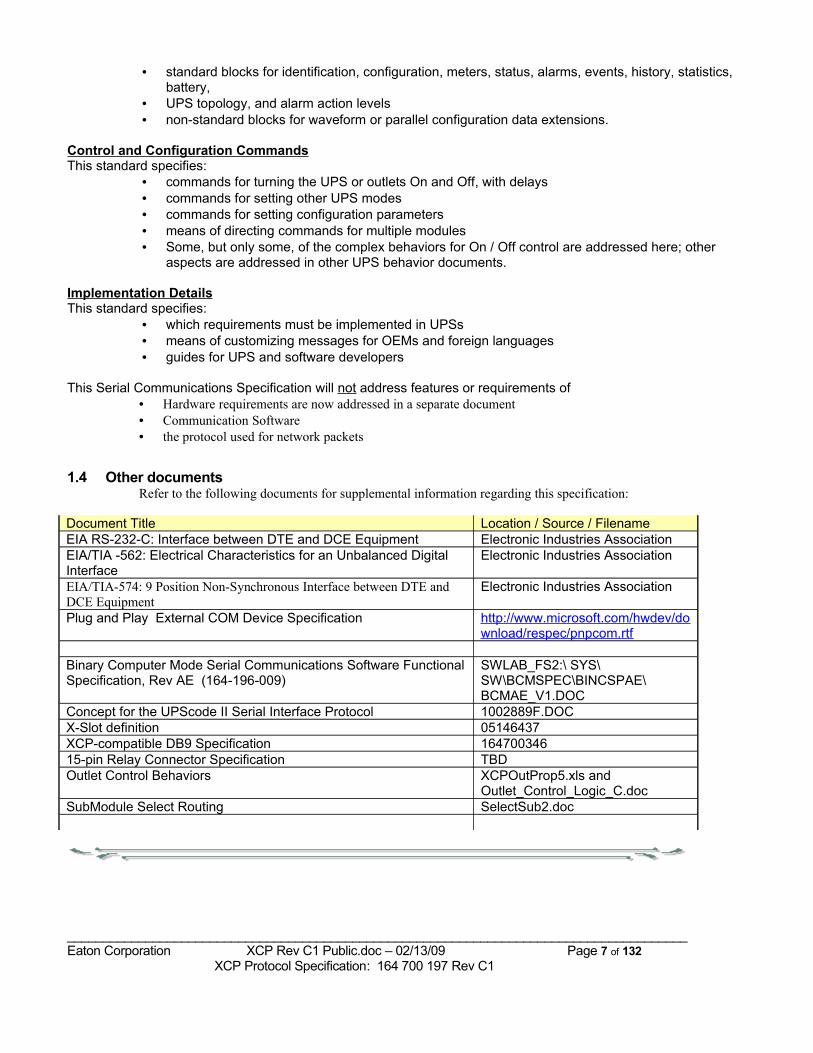
1.4 Other documentsRefer to the following documents for supplemental information regarding this specification:
Document Title Location / Source / FilenameEIA RS-232-C: Interface between DTE and DCE Equipment Electronic Industries AssociationEIA/TIA -562: Electrical Characteristics for an Unbalanced Digital Interface
Electronic Industries Association
EIA/TIA-574: 9 Position Non-Synchronous Interface between DTE and DCE Equipment
Electronic Industries Association
Plug and Play External COM Device Specification http://www.microsoft.com/hwdev/download/respec/pnpcom.rtf
Binary Computer Mode Serial Communications Software Functional Specification, Rev AE (164-196-009)
SWLAB_FS2:\ SYS\SW\BCMSPEC\BINCSPAE\ BCMAE_V1.DOC
Concept for the UPScode II Serial Interface Protocol 1002889F.DOCX-Slot definition 05146437XCP-compatible DB9 Specification 16470034615-pin Relay Connector Specification TBDOutlet Control Behaviors XCPOutProp5.xls and
Outlet_Control_Logic_C.docSubModule Select Routing SelectSub2.doc
_______________________________________________________________________________________Eaton Corporation XCP Rev C1 Public.doc – 02/13/09 Page 7 of 132 XCP Protocol Specification: 164 700 197 Rev C1
2 Hardware Requirements
Editor’s Note: This whole section to be removed, as it is covered in other documents now.Refer to documents:
164700346: XCP-compatible DB9 Specification 05146437: X-Slot Specification document
TBD: 15-pin Relay Connector Specification
_______________________________________________________________________________________Eaton Corporation XCP Rev C1 Public.doc – 02/13/09 Page 8 of 132 XCP Protocol Specification: 164 700 197 Rev C1
3 Protocol Transport specifications3.1 Performance and timing
1. For reliable communication with UPSs with limited CPUs, communication software must be able to implement a SendCommand->WaitForResponse->SendCommand sequence: after sending a command, a host must be able to wait for the UPS response to be completed before sending the next command.
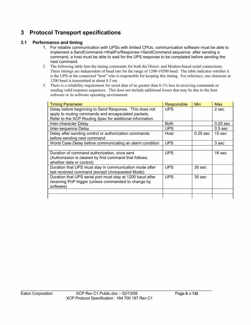
2. The following table lists the timing constraints for both the Direct- and Modem-based serial connections. These timings are independent of baud rate for the range of 1200-19200 baud. The table indicates whether it is the UPS or the connected “host” who is responsible for keeping this timing. For reference, one character at 1200 baud is transmitted in about 8.3 ms.
3. There is a reliability requirement for serial data of no greater than 0.1% loss in receiving commands or sending valid response sequences. This does not include additional losses that may be due to the host software or its software operating environment.
Timing Parameter Responsible Min MaxDelay before beginning to Send Response. This does not apply to routing commands and encapsulated packets. Refer to the XCP Routing Spec for additional information.
UPS 2 sec
Inter-character Delay Both 0.25 secInter-sequence Delay UPS 0.5 secDelay after sending control or authorization commands before sending next command
Host 0.25 sec 15 sec
Worst Case Delay before communicating an alarm condition UPS 3 sec
Duration of command authorization, once sent(Authorizaion is cleared by first command that follows, whether data or control)
UPS 16 sec
Duration that UPS must stay in communication mode after last received command (except Unrequested Mode)
UPS 30 sec
Duration that UPS serial port must stay at 1200 baud after receiving PnP trigger (unless commanded to change by software)
UPS 30 sec
_______________________________________________________________________________________Eaton Corporation XCP Rev C1 Public.doc – 02/13/09 Page 9 of 132 XCP Protocol Specification: 164 700 197 Rev C1
3.2 Direct serial connections
3.2.1 Direct Serial Basics1. Most commands generate a response from the UPS; the (few) exceptions are carefully noted as
such.2. Hardware handshaking may be used, but is not required by this protocol and may not be
implemented by UPSs or communication devices.3. Software handshaking (XON/XOFF) may NOT be used, as these are common values for binary
data.4. Each command must be sent in a separate packet (Header, command, checksum); there cannot
be more than one command in a packet.5. There will be one response to one command or request (not multiple different data blocks in
response to a command); as indicated in Response Format, one response may be made up of multiple sequences.
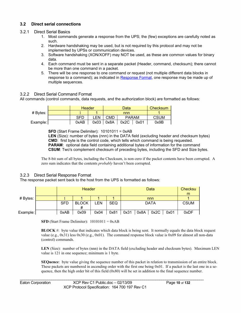
3.2.2 Direct Serial Command FormatAll commands (control commands, data requests, and the authorization block) are formatted as follows:
Header Data Checksum# Bytes: 1 1 nnn 1
SFD LEN CMD PARAM CSUMExample: 0xAB 0x03 0x8A 0x2C 0x01 0x9B
SFD (Start Frame Delimiter): 10101011 = 0xABLEN (Size): number of bytes (nnn) in the DATA field (excluding header and checksum bytes)CMD: first byte is the control code, which tells which command is being requested.PARAM: optional data field containing additional bytes of information for the commandCSUM: Two's complement checksum of preceding bytes, including the SFD and Size bytes.
The 8-bit sum of all bytes, including the Checksum, is non-zero if the packet contents have been corrupted. A zero sum indicates that the contents probably haven’t been corrupted.
3.2.3 Direct Serial Response FormatThe response packet sent back to the host from the UPS is formatted as follows:
Header Data Checksum
# Bytes: 1 1 1 1 nnn 1SFD BLOCK
#LEN SEQ DATA CSUM
Example: 0xAB 0x09 0x04 0x81 0x31 0x8A 0x2C 0x01 0xDF
SFD (Start Frame Delimiter): 10101011 = 0xAB
BLOCK #: byte value that indicates which data block is being sent. It normally equals the data block request value (e.g., 0x31) less 0x30 (e.g., 0x01). The command response block value is 0x09 for almost all non-data (control) commands.
LEN (Size): number of bytes (nnn) in the DATA field (excluding header and checksum bytes). Maximum LEN value is 121 in one sequence; minimum is 1 byte.
SEQuence: byte value giving the sequence number of this packet in relation to transmission of an entire block. These packets are numbered in ascending order with the first one being 0x01. If a packet is the last one in a se-quence, then the high order bit of this field (0x80) will be set in addition to the final sequence number.
_______________________________________________________________________________________Eaton Corporation XCP Rev C1 Public.doc – 02/13/09 Page 10 of 132 XCP Protocol Specification: 164 700 197 Rev C1
DATA: the data bytes
CSUM: Two's complement 8-bit checksum of preceding bytes, includes the SFD through DATA bytes.
Multiple packets: If the data to be sent in response to the data block request exceeds 121 bytes, or if limited resources in the UPS necessitate sending less than 121 bytes per packet, then the data block response is divided into sequences (packets) of data. UPS implementers should attempt to maximize the number of bytes in a data packet in order to maximize the data throughput. The packets which make up the response are sent one after the other until all have been sent, and only then can the next command be processed. The SEQuence numbering for a 3-sequence response would be: 0x01, 0x02, 0x83.The SEQuence number for a single packet response would be 0x81.
Note for UPS developers: There is a way to maximize the number of bytes per sequence even in devices with small (eg, 16 byte) transmit buffers. Try to pack as many bytes, up to 121, as can fit in each sequence, because it's inefficient to send 4-16 bytes with their own header and checksum; for example, with 4 bytes of data: <AB 05 04 01 (data) Csum> -- the 5 bytes of overhead are 56% of each sequence. To maximize throughput, an effective strategy for small buffers is to transmit a block of data like this:
Transmit: AB 05 70 81Transmit: dataTransmit: more dataTransmit: yet more dataTransmit: last data and checksum,
where the device has kept a running checksum as it has been sending.
_______________________________________________________________________________________Eaton Corporation XCP Rev C1 Public.doc – 02/13/09 Page 11 of 132 XCP Protocol Specification: 164 700 197 Rev C1
3.3 Modem-based serial connections: ASCII Computer Mode (ACM)When communicating UPS data via modem, it is necessary to encode the binary data into a limited set of ASCII characters to prevent:
• Inadvertently sending a character sequence which could be interpreted as requesting that the modem go into command mode.
• Inadvertently putting the modem into test mode or altering its defaults, if the modem were to hang up due to external circumstances.
3.3.1 Modem Serial Basics 1. The same set of commands and responses are used as for Direct serial connections.2. Each binary byte is encoded into two ASCII characters by dividing it into two 4-bit nibbles, and adding
0x30 to each 0-9 nibble or 0x37 to each A-F nibble. Thus, a binary 0xA5 becomes ASCII 0x41, 0x35 ( printable characters “A5”). This ASCII encoding only applies to XCP commands and responses, and not to other UPS menu, configuration or status “screens”.
3. An optional <CR><LF> sequence may be sent after the checksum.4. For modem-based serial connections, a different, password-based mechanism is used for authorizing
control commands; see the section on Command Authorization.
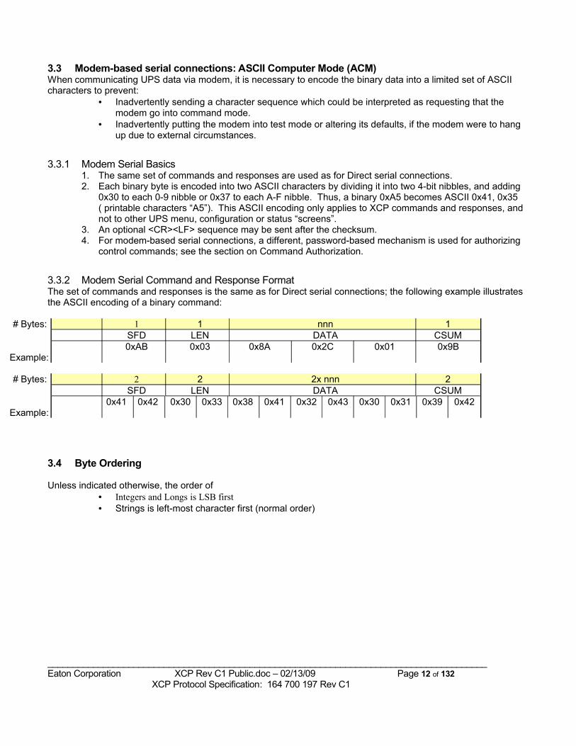
3.3.2 Modem Serial Command and Response FormatThe set of commands and responses is the same as for Direct serial connections; the following example illustrates the ASCII encoding of a binary command:
# Bytes: 1 1 nnn 1SFD LEN DATA CSUM
Example:0xAB 0x03 0x8A 0x2C 0x01 0x9B
# Bytes: 2 2 2x nnn 2SFD LEN DATA CSUM
Example:0x41 0x42 0x30 0x33 0x38 0x41 0x32 0x43 0x30 0x31 0x39 0x42
3.4 Byte Ordering
Unless indicated otherwise, the order of• Integers and Longs is LSB first• Strings is left-most character first (normal order)
_______________________________________________________________________________________Eaton Corporation XCP Rev C1 Public.doc – 02/13/09 Page 12 of 132 XCP Protocol Specification: 164 700 197 Rev C1
3.5 Data and Map FormatsSeveral data formats are supported for the Meters and Statistics blocks; the format used for each meter is indicated by the value of its non-zero map byte.
Type: Floating Point Map Value: 0xWR Example: 0x51For a floating-point meter, the byte in the Meter Map suggests how to display the meter value.
The map byte is a packed Binary Coded Decimal (BCD) value. The upper nibble, ‘W’, of the BCD value gives the number of places recommended to display the meter data at its maximum value. This includes the decimal point. For example, if the maximum value were '100.0' then the upper nibble would be a 5. The lower nibble, ‘R’, informs you of how many digits are intended to be shown to the right of the decimal point. In the case above, the lower nibble would be 1, giving a BCD value of 0x51 for the Meter Map entry.
The maximum value permitted for floating point map values is 0x97. The lower nibble ‘R’ must not exceed (the value of the upper nibble) ‘W’ - 2, to allow for the “0.” prefix.
Data format for floating point meters:
The meter values are expressed in 32-bit IEEE-754 floating-point format. Following the LSB first convention, a value of 3.141592654 decimal = 0x40490FDB (hex float), and the transmission sequence is DB 0F 49 40.
Type: Fixed Point Integer Map Value: 0xFn Example: 0xF0If the meter value is a 32 bit signed integer, then the map byte value would be 0xFn (which is an invalid BCD number). For whole-valued integers, the map byte value is ordinarily 0xF0. If the lower nibble value, n, is non-zero, then it indicates a fixed-point format, and n is the number of bits in the value after the decimal. A common example would be to have a 24.8 format, with a map byte of 0xF8; e.g., a meter value of 0x00003BC0 would correspond to 59.75 To convert the reading to real units, divide the reading by 2n; for the example above, 0x00003BC0 / 28 = 59.75 Type: Seconds Map Value: 0xE2 Example: 0xE2If the units of a meter are time in Seconds (e.g., Meter 36, Battery Time Remaining), then the map byte is specified as 0xE2. 0xE2 is preferred for new implementations, but 0xF0 may be found in older implementations.
_______________________________________________________________________________________Eaton Corporation XCP Rev C1 Public.doc – 02/13/09 Page 13 of 132 XCP Protocol Specification: 164 700 197 Rev C1
3.5.1 Date Format for Meters
Type: Date Map Value: 0xE0 Example: 0xE0If a Date meter (e.g., Meter 73) is used, then it should be specified as 0xE0 in the Meter Map.
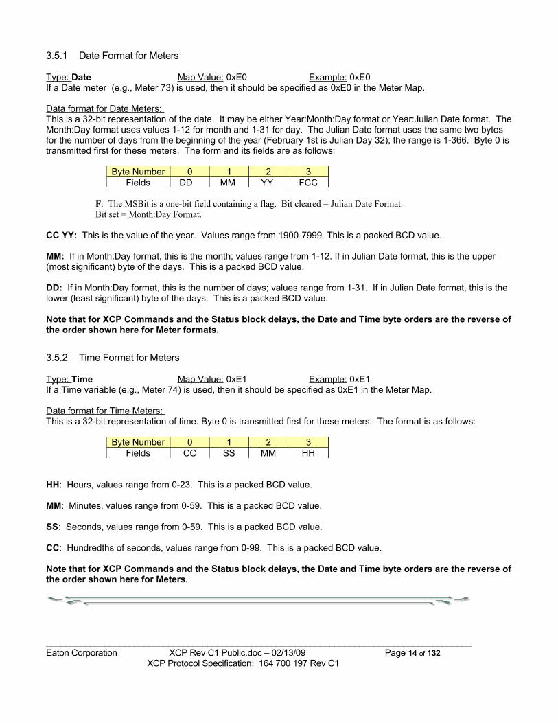
Data format for Date Meters: This is a 32-bit representation of the date. It may be either Year:Month:Day format or Year:Julian Date format. The Month:Day format uses values 1-12 for month and 1-31 for day. The Julian Date format uses the same two bytes for the number of days from the beginning of the year (February 1st is Julian Day 32); the range is 1-366. Byte 0 is transmitted first for these meters. The form and its fields are as follows:
Byte Number 0 1 2 3Fields DD MM YY FCC
F: The MSBit is a one-bit field containing a flag. Bit cleared = Julian Date Format. Bit set = Month:Day Format.
CC YY: This is the value of the year. Values range from 1900-7999. This is a packed BCD value.
MM: If in Month:Day format, this is the month; values range from 1-12. If in Julian Date format, this is the upper (most significant) byte of the days. This is a packed BCD value.
DD: If in Month:Day format, this is the number of days; values range from 1-31. If in Julian Date format, this is the lower (least significant) byte of the days. This is a packed BCD value.
Note that for XCP Commands and the Status block delays, the Date and Time byte orders are the reverse of the order shown here for Meter formats.
3.5.2 Time Format for Meters
Type: Time Map Value: 0xE1 Example: 0xE1If a Time variable (e.g., Meter 74) is used, then it should be specified as 0xE1 in the Meter Map.
Data format for Time Meters: This is a 32-bit representation of time. Byte 0 is transmitted first for these meters. The format is as follows:
Byte Number 0 1 2 3Fields CC SS MM HH
HH: Hours, values range from 0-23. This is a packed BCD value.
MM: Minutes, values range from 0-59. This is a packed BCD value.
SS: Seconds, values range from 0-59. This is a packed BCD value.
CC: Hundredths of seconds, values range from 0-99. This is a packed BCD value.
Note that for XCP Commands and the Status block delays, the Date and Time byte orders are the reverse of the order shown here for Meters.
_______________________________________________________________________________________Eaton Corporation XCP Rev C1 Public.doc – 02/13/09 Page 14 of 132 XCP Protocol Specification: 164 700 197 Rev C1
4 Operational Requirements
4.1 UPS Discovery A fast, reliable means of “discovering” that an Powerware UPS is serially connected is essential to minimize communication software overhead and customer frustration. Either (preferably both) of the following methods MUST be implemented in both the UPS and software products to achieve this goal (refer to the Timing table):
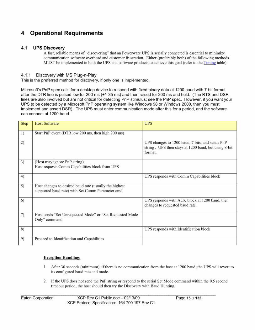
4.1.1 Discovery with MS Plug-n-Play This is the preferred method for discovery, if only one is implemented.
Microsoft’s PnP spec calls for a desktop device to respond with fixed binary data at 1200 baud with 7-bit format after the DTR line is pulsed low for 200 ms (+/- 35 ms) and then raised for 200 ms and held. (The RTS and DSR lines are also involved but are not critical for detecting PnP stimulus; see the PnP spec. However, if you want your UPS to be detected by a Microsoft PnP operating system like Windows 98 or Windows 2000, then you must implement and assert DSR). The UPS must enter communication mode after this for a period, and the software can connect at 1200 baud.
Step Host Software UPS
1) Start PnP event (DTR low 200 ms, then high 200 ms)
2) UPS changes to 1200 baud, 7 bits, and sends PnP string . UPS then stays at 1200 baud, but using 8-bit format.
3) (Host may ignore PnP string)Host requests Comm Capabilities block from UPS
4) UPS responds with Comm Capabilities block
5) Host changes to desired baud rate (usually the highest supported baud rate) with Set Comm Parameter cmd
6) UPS responds with ACK block at 1200 baud, then changes to requested baud rate.
7) Host sends “Set Unrequested Mode” or “Set Requested Mode Only” command
8) UPS responds with Identification block
9) Proceed to Identification and Capabilities
Exception Handling:
1. After 30 seconds (minimum), if there is no communication from the host at 1200 baud, the UPS will revert to its configured baud rate and mode.
2. If the UPS does not send the PnP string or respond to the serial Set Mode command within the 0.5 second timeout period, the host should then try the Discovery with Baud Hunting.
_______________________________________________________________________________________Eaton Corporation XCP Rev C1 Public.doc – 02/13/09 Page 15 of 132 XCP Protocol Specification: 164 700 197 Rev C1
3. If the UPS cannot support 7-bit mode when transmitting the PnP message, it can achieve an equivalent result in 8-bit mode if it sets the MSbit to 1 before transmitting. This appears to the host as 7-bit data with 2 Stop bits, which is not a problem.
4. If the UPS does not ACK the Set Comm Param command (to change the baud rate), then both the UPS and host stay at 1200 baud for futher XCP communication.
5. If the UPS does not support the Send Comm Capabilities data block (command 0x42), the host software should continue to communicate at 1200 baud.
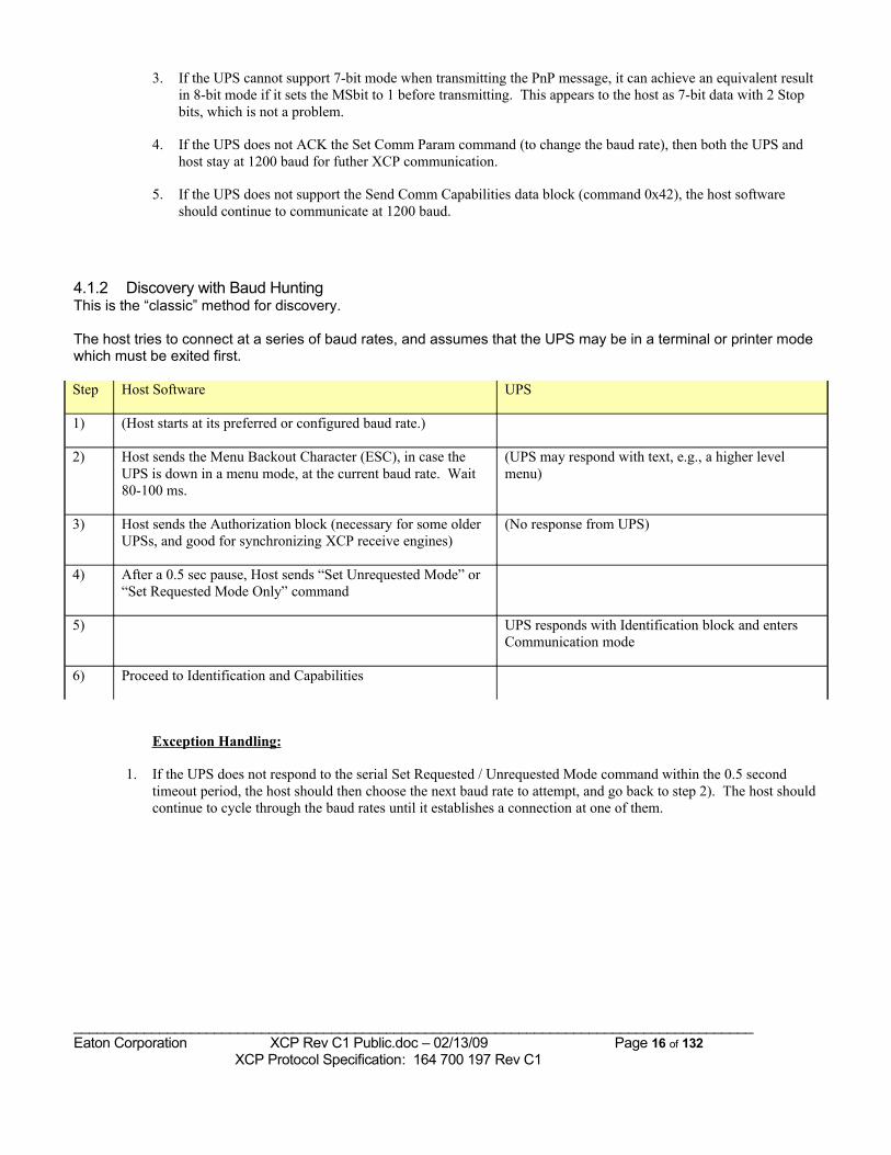
4.1.2 Discovery with Baud Hunting This is the “classic” method for discovery.
The host tries to connect at a series of baud rates, and assumes that the UPS may be in a terminal or printer mode which must be exited first.
Step Host Software UPS
1) (Host starts at its preferred or configured baud rate.)
2) Host sends the Menu Backout Character (ESC), in case the UPS is down in a menu mode, at the current baud rate. Wait 80-100 ms.
(UPS may respond with text, e.g., a higher level menu)
3) Host sends the Authorization block (necessary for some older UPSs, and good for synchronizing XCP receive engines)
(No response from UPS)
4) After a 0.5 sec pause, Host sends “Set Unrequested Mode” or “Set Requested Mode Only” command
5) UPS responds with Identification block and enters Communication mode
6) Proceed to Identification and Capabilities
Exception Handling:
1. If the UPS does not respond to the serial Set Requested / Unrequested Mode command within the 0.5 second timeout period, the host should then choose the next baud rate to attempt, and go back to step 2). The host should continue to cycle through the baud rates until it establishes a connection at one of them.
_______________________________________________________________________________________Eaton Corporation XCP Rev C1 Public.doc – 02/13/09 Page 16 of 132 XCP Protocol Specification: 164 700 197 Rev C1
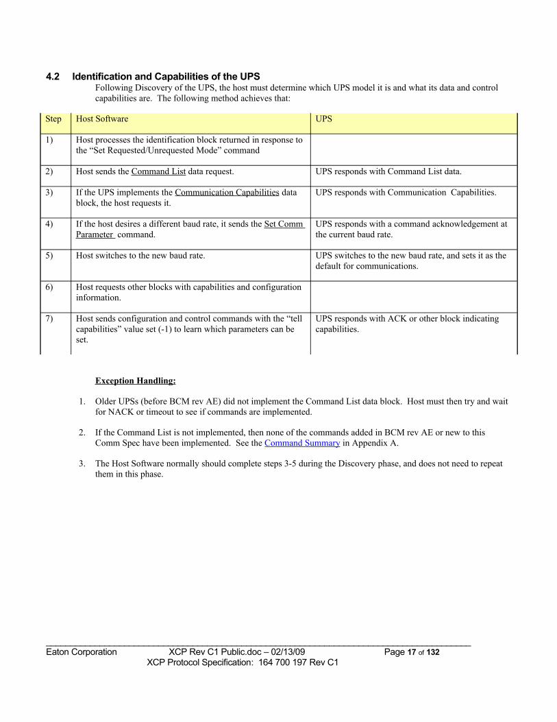
4.2 Identification and Capabilities of the UPS Following Discovery of the UPS, the host must determine which UPS model it is and what its data and control capabilities are. The following method achieves that:
Step Host Software UPS
1) Host processes the identification block returned in response to the “Set Requested/Unrequested Mode” command
2) Host sends the Command List data request. UPS responds with Command List data.
3) If the UPS implements the Communication Capabilities data block, the host requests it.
UPS responds with Communication Capabilities.
4) If the host desires a different baud rate, it sends the Set Comm Parameter command.
UPS responds with a command acknowledgement at the current baud rate.
5) Host switches to the new baud rate. UPS switches to the new baud rate, and sets it as the default for communications.
6) Host requests other blocks with capabilities and configuration information.
7) Host sends configuration and control commands with the “tell capabilities” value set (-1) to learn which parameters can be set.
UPS responds with ACK or other block indicating capabilities.
Exception Handling:
1. Older UPSs (before BCM rev AE) did not implement the Command List data block. Host must then try and wait for NACK or timeout to see if commands are implemented.
2. If the Command List is not implemented, then none of the commands added in BCM rev AE or new to this Comm Spec have been implemented. See the Command Summary in Appendix A.
3. The Host Software normally should complete steps 3-5 during the Discovery phase, and does not need to repeat them in this phase.
_______________________________________________________________________________________Eaton Corporation XCP Rev C1 Public.doc – 02/13/09 Page 17 of 132 XCP Protocol Specification: 164 700 197 Rev C1
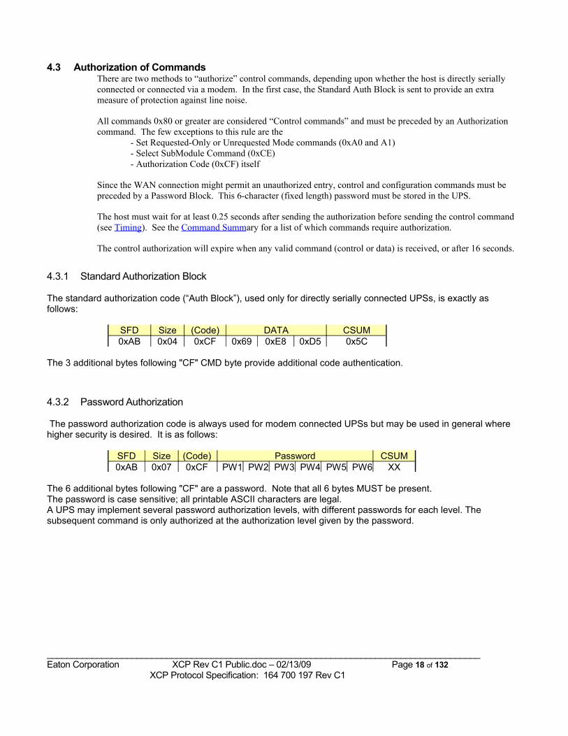
4.3 Authorization of CommandsThere are two methods to “authorize” control commands, depending upon whether the host is directly serially connected or connected via a modem. In the first case, the Standard Auth Block is sent to provide an extra measure of protection against line noise.
All commands 0x80 or greater are considered “Control commands” and must be preceded by an Authorization command. The few exceptions to this rule are the
- Set Requested-Only or Unrequested Mode commands (0xA0 and A1)- Select SubModule Command (0xCE)- Authorization Code (0xCF) itself
Since the WAN connection might permit an unauthorized entry, control and configuration commands must be preceded by a Password Block. This 6-character (fixed length) password must be stored in the UPS.
The host must wait for at least 0.25 seconds after sending the authorization before sending the control command (see Timing). See the Command Summary for a list of which commands require authorization.
The control authorization will expire when any valid command (control or data) is received, or after 16 seconds.
4.3.1 Standard Authorization Block
The standard authorization code (“Auth Block”), used only for directly serially connected UPSs, is exactly as follows:
SFD Size (Code) DATA CSUM0xAB 0x04 0xCF 0x69 0xE8 0xD5 0x5C
The 3 additional bytes following "CF" CMD byte provide additional code authentication.
4.3.2 Password Authorization
The password authorization code is always used for modem connected UPSs but may be used in general where higher security is desired. It is as follows:
SFD Size (Code) Password CSUM0xAB 0x07 0xCF PW1 PW2 PW3 PW4 PW5 PW6 XX
The 6 additional bytes following "CF" are a password. Note that all 6 bytes MUST be present.The password is case sensitive; all printable ASCII characters are legal. A UPS may implement several password authorization levels, with different passwords for each level. The subsequent command is only authorized at the authorization level given by the password.
_______________________________________________________________________________________Eaton Corporation XCP Rev C1 Public.doc – 02/13/09 Page 18 of 132 XCP Protocol Specification: 164 700 197 Rev C1
4.4 Response to CommandsThe response to all data request commands (0x30 to 0x5F) is the requested data block; these are described in the next chapter. However, there is a data block reserved to serve as the response to control and configuration commands: the Command Acknowledge Block (“ACK block”).
Each data block response in this document is described with the following format:
1. Requesting Command : the command byte or bytes used to request the data block2. Structure of Data Response : the structure of the response data, without the header and checksum,
and independent of the means of dividing the block into multiple sequences3. Additional Field Descriptions : optional, for those fields which require a longer explanation4. Exceptions : Notes on known variations in UPS implementations5. Example(s) : Optional example(s) of simple responses
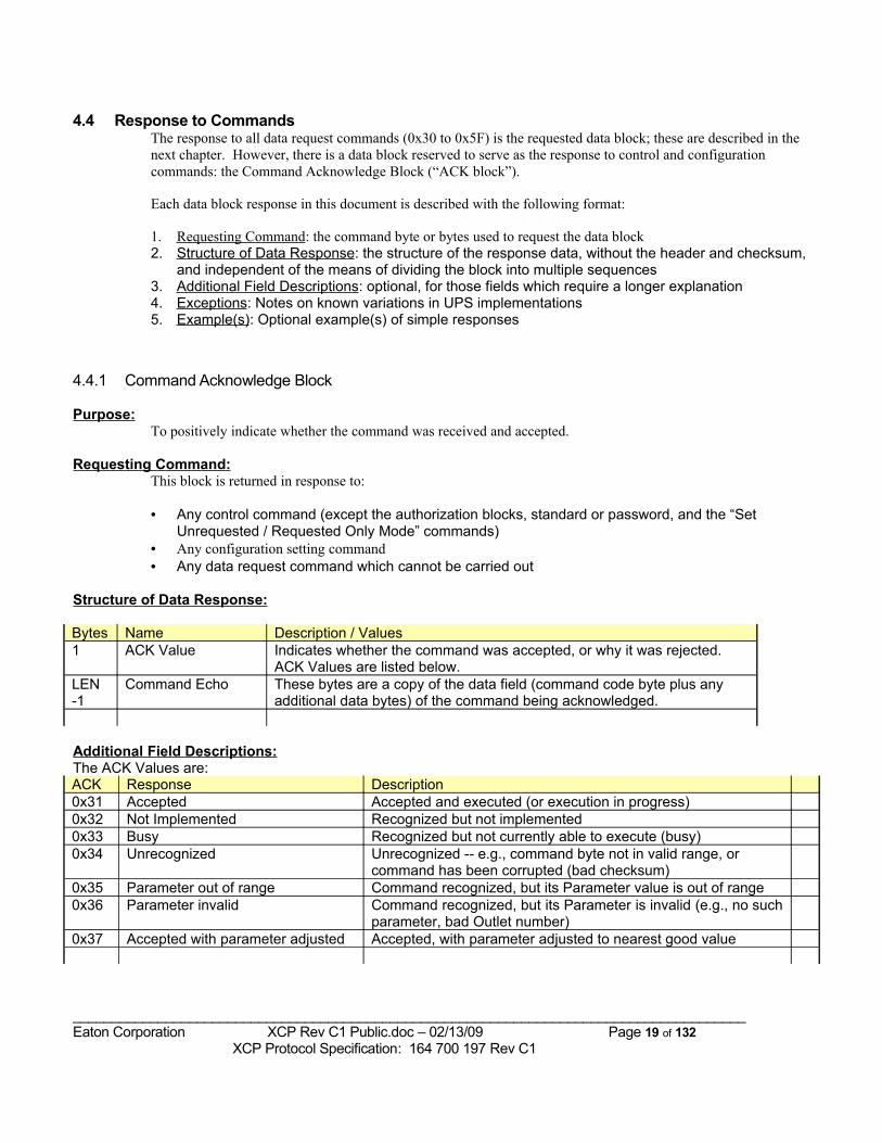
4.4.1 Command Acknowledge Block
Purpose:To positively indicate whether the command was received and accepted.
Requesting Command:This block is returned in response to:
• Any control command (except the authorization blocks, standard or password, and the “Set Unrequested / Requested Only Mode” commands)
• Any configuration setting command• Any data request command which cannot be carried out
Structure of Data Response:
Bytes Name Description / Values1 ACK Value Indicates whether the command was accepted, or why it was rejected.
ACK Values are listed below.LEN -1
Command Echo These bytes are a copy of the data field (command code byte plus any additional data bytes) of the command being acknowledged.
Additional Field Descriptions:The ACK Values are:ACK Response Description0x31 Accepted Accepted and executed (or execution in progress)0x32 Not Implemented Recognized but not implemented0x33 Busy Recognized but not currently able to execute (busy)0x34 Unrecognized Unrecognized -- e.g., command byte not in valid range, or
command has been corrupted (bad checksum)0x35 Parameter out of range Command recognized, but its Parameter value is out of range 0x36 Parameter invalid Command recognized, but its Parameter is invalid (e.g., no such
parameter, bad Outlet number)0x37 Accepted with parameter adjusted Accepted, with parameter adjusted to nearest good value
_______________________________________________________________________________________Eaton Corporation XCP Rev C1 Public.doc – 02/13/09 Page 19 of 132 XCP Protocol Specification: 164 700 197 Rev C1
The "Parameter out of range" response reflects an unacceptable value in the command; the "Parameter invalid" response occurs when a secondary command byte (Parameter number), which is not the value portion of the command, is invalid.
Exceptions: UPSs with BCM rev W or earlier do not implement the ACK block.
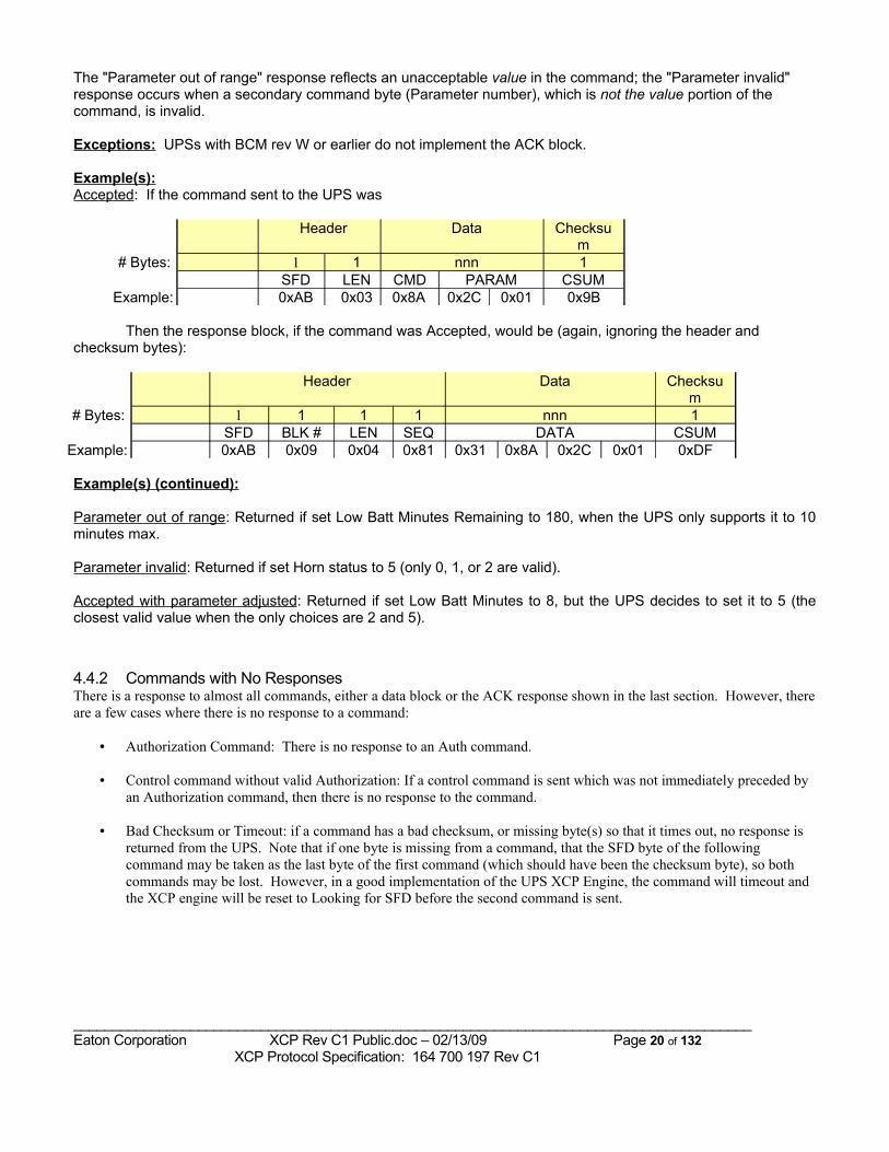
Example(s):Accepted: If the command sent to the UPS was
Header Data Checksum
# Bytes: 1 1 nnn 1SFD LEN CMD PARAM CSUM
Example: 0xAB 0x03 0x8A 0x2C 0x01 0x9B
Then the response block, if the command was Accepted, would be (again, ignoring the header and checksum bytes):
Header Data Checksum
# Bytes: 1 1 1 1 nnn 1SFD BLK # LEN SEQ DATA CSUM
Example: 0xAB 0x09 0x04 0x81 0x31 0x8A 0x2C 0x01 0xDF
Example(s) (continued):
Parameter out of range: Returned if set Low Batt Minutes Remaining to 180, when the UPS only supports it to 10 minutes max.
Parameter invalid: Returned if set Horn status to 5 (only 0, 1, or 2 are valid).
Accepted with parameter adjusted: Returned if set Low Batt Minutes to 8, but the UPS decides to set it to 5 (the closest valid value when the only choices are 2 and 5).
4.4.2 Commands with No ResponsesThere is a response to almost all commands, either a data block or the ACK response shown in the last section. However, there are a few cases where there is no response to a command:
• Authorization Command: There is no response to an Auth command.
• Control command without valid Authorization: If a control command is sent which was not immediately preceded by an Authorization command, then there is no response to the command.
• Bad Checksum or Timeout: if a command has a bad checksum, or missing byte(s) so that it times out, no response is returned from the UPS. Note that if one byte is missing from a command, that the SFD byte of the following command may be taken as the last byte of the first command (which should have been the checksum byte), so both commands may be lost. However, in a good implementation of the UPS XCP Engine, the command will timeout and the XCP engine will be reset to Looking for SFD before the second command is sent.
_______________________________________________________________________________________Eaton Corporation XCP Rev C1 Public.doc – 02/13/09 Page 20 of 132 XCP Protocol Specification: 164 700 197 Rev C1
4.5 Unrequested Data OutputOne customer-requested shutdown software application has one “master” host connected to the UPS to send and receive serial data, and one or more “slave” hosts which can receive output from the UPS, but not send commands or requests to it. Unrequested Mode is required to ensure timely data updates for the slave hosts if the master host should become unavailable. In this mode:
• The UPS enters Unrequested mode when sent the “Set Unrequested Mode” command. It does not leave this mode until specifically commanded to do so with an “Exit XCP” or "Set Requested-Only Mode" command.
• Status and alarm information is provided every 30 seconds if there are no input requests from the master host.• The status and alarms will also be sent whenever there is a change in status or alarms.• Identification information must also be sent periodically, at least once every 2 minutes.• It is recommended that the Meters block be sent every 30 seconds as well.• It is recommended that the UPS be able to restart in Unrequested Mode if it was in this mode at the time of
the last power down.
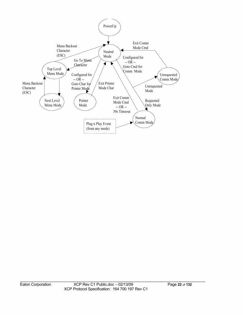
4.6 Compatibility with User Terminal and Printer modesSome UPSs have a User Terminal and/or Printer mode. If one is implemented, the following requirements apply:
• The initial power-up mode must either be the Communication mode, a “printer” mode, or a neutral mode. The UPS should remember the last mode it was in and start in this mode.
• There is a standard character, <ESC> (0x1B), used to back out of the menus and exit the Terminal mode. This is required so that the Communication Software can reliably back out of the menus, in case the UPS was left in terminal mode.
• An Exit XCP command (0xFA) is used to exit the Communication mode and return to Terminal mode.• Menu, Printer and Communication modes are exclusive; the UPS can only be in one at a time.• There is a timeout option for Communication mode; may leave after no communication for 30 seconds
(minimum) unless in Unrequested mode (see Timing).• May make plain text service command requests while in Communication mode.• If the Baud Rate is changed in Communication Mode, the new baud rate should be saved as the
“Configured” Baud Rate
The following diagram illustrates the states for Printer, Menu, and Comm Spec modes, including the means of transition. The “Neutral” state may not exist as more than a transient, or it may be a stable state.
_______________________________________________________________________________________Eaton Corporation XCP Rev C1 Public.doc – 02/13/09 Page 21 of 132 XCP Protocol Specification: 164 700 197 Rev C1
Top LevelMenu Mode
NormalComm Mode
Next LevelMenu Mode
NeutralMode Configured for
-- OR --Goto Cmd forComm Mode
Menu BackoutCharacter(ESC)
Menu BackoutCharacter(ESC)
Go To MenuCharacter
Plug n Play Event(from any mode)
Exit CommMode Cmd -- OR --30s Timeout
PowerUp
PrinterMode
UnrequestedComm Mode
Configured for -- OR --Goto Char forPrinter Mode
Exit PrinterMode Char
Exit CommMode Cmd
UnrequestedMode
RequestedOnly Mode
_______________________________________________________________________________________Eaton Corporation XCP Rev C1 Public.doc – 02/13/09 Page 22 of 132 XCP Protocol Specification: 164 700 197 Rev C1
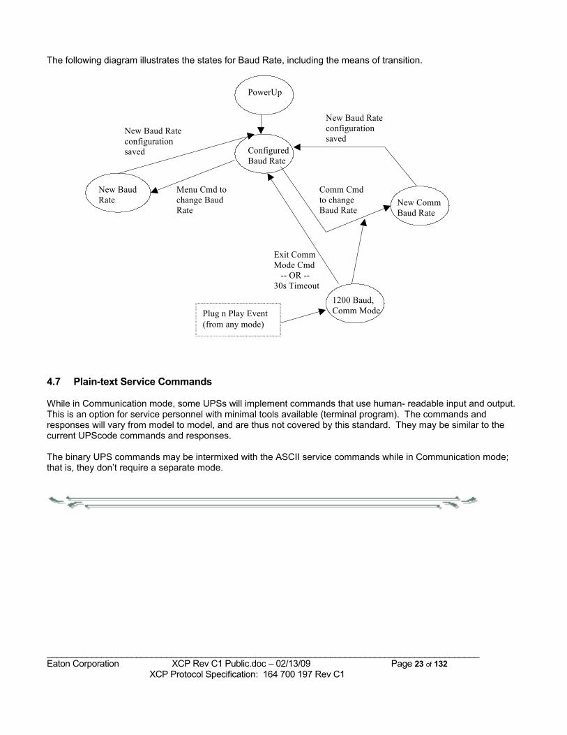
The following diagram illustrates the states for Baud Rate, including the means of transition.
New BaudRate
1200 Baud,Comm Mode
ConfiguredBaud Rate
Comm Cmdto changeBaud Rate
Menu Cmd tochange BaudRate
Plug n Play Event(from any mode)
Exit CommMode Cmd -- OR --30s Timeout
PowerUp
New CommBaud Rate
New Baud Rateconfigurationsaved
New Baud Rateconfigurationsaved
4.7 Plain-text Service Commands
While in Communication mode, some UPSs will implement commands that use human- readable input and output. This is an option for service personnel with minimal tools available (terminal program). The commands and responses will vary from model to model, and are thus not covered by this standard. They may be similar to the current UPScode commands and responses.
The binary UPS commands may be intermixed with the ASCII service commands while in Communication mode; that is, they don’t require a separate mode.
_______________________________________________________________________________________Eaton Corporation XCP Rev C1 Public.doc – 02/13/09 Page 23 of 132 XCP Protocol Specification: 164 700 197 Rev C1
5 Standard Data blocksThe requirements in this section are for the protocol overall; specific UPS models will not implement all these protocol items. The Command List block should indicate which data blocks have been implemented.
5.1 UPS Capabilities The UPS will use the following data blocks to indicate its capabilities:1. The Identification block in response to the “Set Unrequested / Requested-Only Mode” command.2. The Command List block3. The Communication Capabilities and Communication Port List blocks4. The Config and Extended Limits blocks5. Responses to configuration commands with the parameter field set to “Show Capabilities (0xFF)”.
The commands which do this (described in their sections below) are:• The Waveform Block request• The Set Config Parameters command• The Set Communications Parameter command• Request a Systems Test command• Set Scratchpad Sector command• Set Power Strategy Command
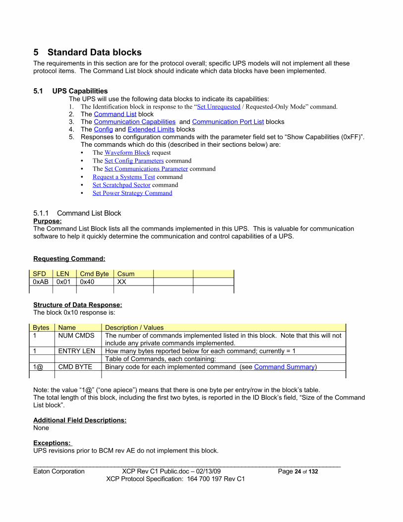
5.1.1 Command List Block Purpose:The Command List Block lists all the commands implemented in this UPS. This is valuable for communication software to help it quickly determine the communication and control capabilities of a UPS.
Requesting Command:
SFD LEN Cmd Byte Csum0xAB 0x01 0x40 XX
Structure of Data Response:The block 0x10 response is:
Bytes Name Description / Values1 NUM CMDS The number of commands implemented listed in this block. Note that this will not
include any private commands implemented.1 ENTRY LEN How many bytes reported below for each command; currently = 1
Table of Commands, each containing:1@ CMD BYTE Binary code for each implemented command (see Command Summary)
Note: the value “1@” (“one apiece”) means that there is one byte per entry/row in the block’s table.The total length of this block, including the first two bytes, is reported in the ID Block’s field, “Size of the Command List block”.
Additional Field Descriptions:None
Exceptions: UPS revisions prior to BCM rev AE do not implement this block.
_______________________________________________________________________________________Eaton Corporation XCP Rev C1 Public.doc – 02/13/09 Page 24 of 132 XCP Protocol Specification: 164 700 197 Rev C1
Example(s):
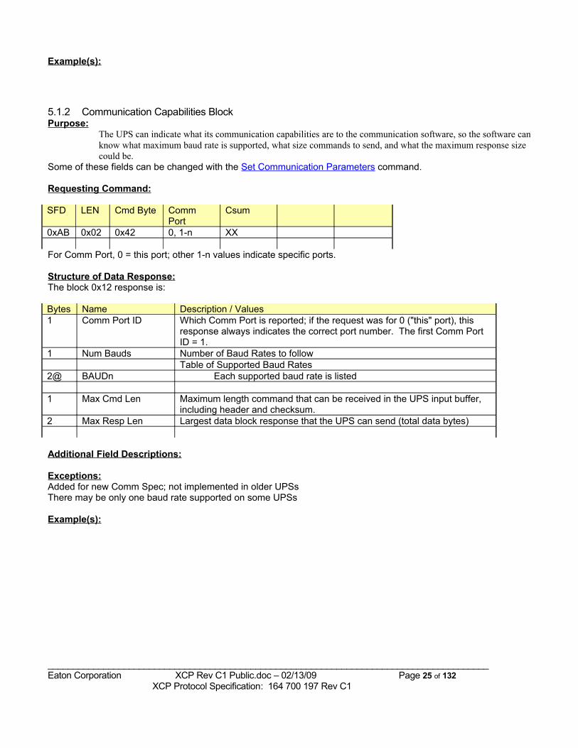
5.1.2 Communication Capabilities BlockPurpose:
The UPS can indicate what its communication capabilities are to the communication software, so the software can know what maximum baud rate is supported, what size commands to send, and what the maximum response size could be.
Some of these fields can be changed with the Set Communication Parameters command.
Requesting Command:
SFD LEN Cmd Byte Comm Port
Csum
0xAB 0x02 0x42 0, 1-n XX
For Comm Port, 0 = this port; other 1-n values indicate specific ports.
Structure of Data Response:The block 0x12 response is:
Bytes Name Description / Values1 Comm Port ID Which Comm Port is reported; if the request was for 0 ("this" port), this
response always indicates the correct port number. The first Comm Port ID = 1.
1 Num Bauds Number of Baud Rates to followTable of Supported Baud Rates
2@ BAUDn Each supported baud rate is listed
1 Max Cmd Len Maximum length command that can be received in the UPS input buffer, including header and checksum.
2 Max Resp Len Largest data block response that the UPS can send (total data bytes)
Additional Field Descriptions:
Exceptions:Added for new Comm Spec; not implemented in older UPSsThere may be only one baud rate supported on some UPSs
Example(s):
_______________________________________________________________________________________Eaton Corporation XCP Rev C1 Public.doc – 02/13/09 Page 25 of 132 XCP Protocol Specification: 164 700 197 Rev C1
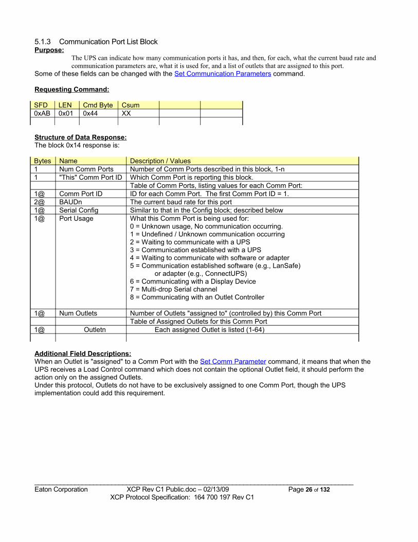
5.1.3 Communication Port List BlockPurpose:
The UPS can indicate how many communication ports it has, and then, for each, what the current baud rate and communication parameters are, what it is used for, and a list of outlets that are assigned to this port.
Some of these fields can be changed with the Set Communication Parameters command.
Requesting Command:
SFD LEN Cmd Byte Csum0xAB 0x01 0x44 XX
Structure of Data Response:The block 0x14 response is:
Bytes Name Description / Values1 Num Comm Ports Number of Comm Ports described in this block, 1-n1 "This" Comm Port ID Which Comm Port is reporting this block.
Table of Comm Ports, listing values for each Comm Port:1@ Comm Port ID ID for each Comm Port. The first Comm Port ID = 1.2@ BAUDn The current baud rate for this port1@ Serial Config Similar to that in the Config block; described below1@ Port Usage What this Comm Port is being used for:
0 = Unknown usage, No communication occurring.1 = Undefined / Unknown communication occurring2 = Waiting to communicate with a UPS3 = Communication established with a UPS4 = Waiting to communicate with software or adapter5 = Communication established software (e.g., LanSafe)
or adapter (e.g., ConnectUPS)6 = Communicating with a Display Device7 = Multi-drop Serial channel8 = Communicating with an Outlet Controller
1@ Num Outlets Number of Outlets "assigned to" (controlled by) this Comm PortTable of Assigned Outlets for this Comm Port
1@ Outletn Each assigned Outlet is listed (1-64)
Additional Field Descriptions:When an Outlet is "assigned" to a Comm Port with the Set Comm Parameter command, it means that when the UPS receives a Load Control command which does not contain the optional Outlet field, it should perform the action only on the assigned Outlets.Under this protocol, Outlets do not have to be exclusively assigned to one Comm Port, though the UPS implementation could add this requirement.
_______________________________________________________________________________________Eaton Corporation XCP Rev C1 Public.doc – 02/13/09 Page 26 of 132 XCP Protocol Specification: 164 700 197 Rev C1
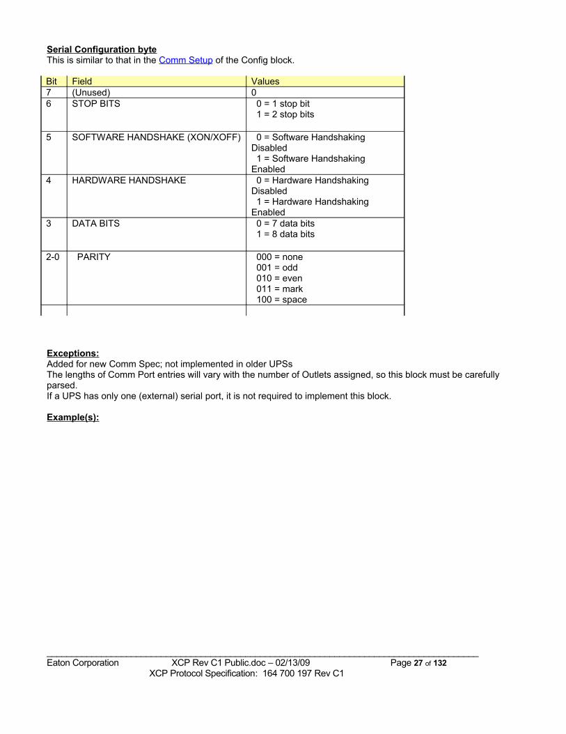
Serial Configuration byteThis is similar to that in the Comm Setup of the Config block.
Bit Field Values7 (Unused) 06 STOP BITS 0 = 1 stop bit
1 = 2 stop bits
5 SOFTWARE HANDSHAKE (XON/XOFF) 0 = Software Handshaking Disabled 1 = Software Handshaking Enabled
4 HARDWARE HANDSHAKE 0 = Hardware Handshaking Disabled 1 = Hardware Handshaking Enabled
3 DATA BITS 0 = 7 data bits 1 = 8 data bits
2-0 PARITY 000 = none 001 = odd 010 = even 011 = mark 100 = space
Exceptions:Added for new Comm Spec; not implemented in older UPSsThe lengths of Comm Port entries will vary with the number of Outlets assigned, so this block must be carefully parsed.If a UPS has only one (external) serial port, it is not required to implement this block.
Example(s):
_______________________________________________________________________________________Eaton Corporation XCP Rev C1 Public.doc – 02/13/09 Page 27 of 132 XCP Protocol Specification: 164 700 197 Rev C1
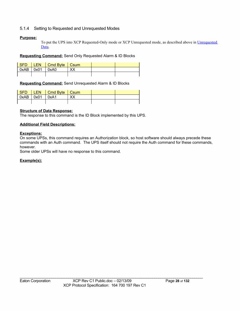
5.1.4 Setting to Requested and Unrequested Modes
Purpose:To put the UPS into XCP Requested-Only mode or XCP Unrequested mode, as described above in Unrequested Data.
Requesting Command: Send Only Requested Alarm & ID Blocks
SFD LEN Cmd Byte Csum0xAB 0x01 0xA0 XX
Requesting Command: Send Unrequested Alarm & ID Blocks
SFD LEN Cmd Byte Csum0xAB 0x01 0xA1 XX
Structure of Data Response:The response to this command is the ID Block implemented by this UPS.
Additional Field Descriptions:
Exceptions:On some UPSs, this command requires an Authorization block, so host software should always precede these commands with an Auth command. The UPS itself should not require the Auth command for these commands, however.Some older UPSs will have no response to this command.
Example(s):
_______________________________________________________________________________________Eaton Corporation XCP Rev C1 Public.doc – 02/13/09 Page 28 of 132 XCP Protocol Specification: 164 700 197 Rev C1
5.2 Identification and Configuration The UPS must have a way of reporting its Identification and Configuration information, including:
• Model name (must not have Manufacturer in the text)• VA rating• “manufacturer”• Serial and model or CTO numbers• Customer-set identification string• nominal input and output volts, amps, VA, power, and frequency• Identification of submodules: version, name or part #
There are 3 blocks defined to do this; they are:• Standard ID data block• Configuration data block• Extended Limits data block
The response to the Send Unrequested / Requested Only Mode commands is always to send the Identification block implemented in the UPS.
Some other blocks which describe relatively static information about the UPS are• Communication Capabilities block• UPS Topology block
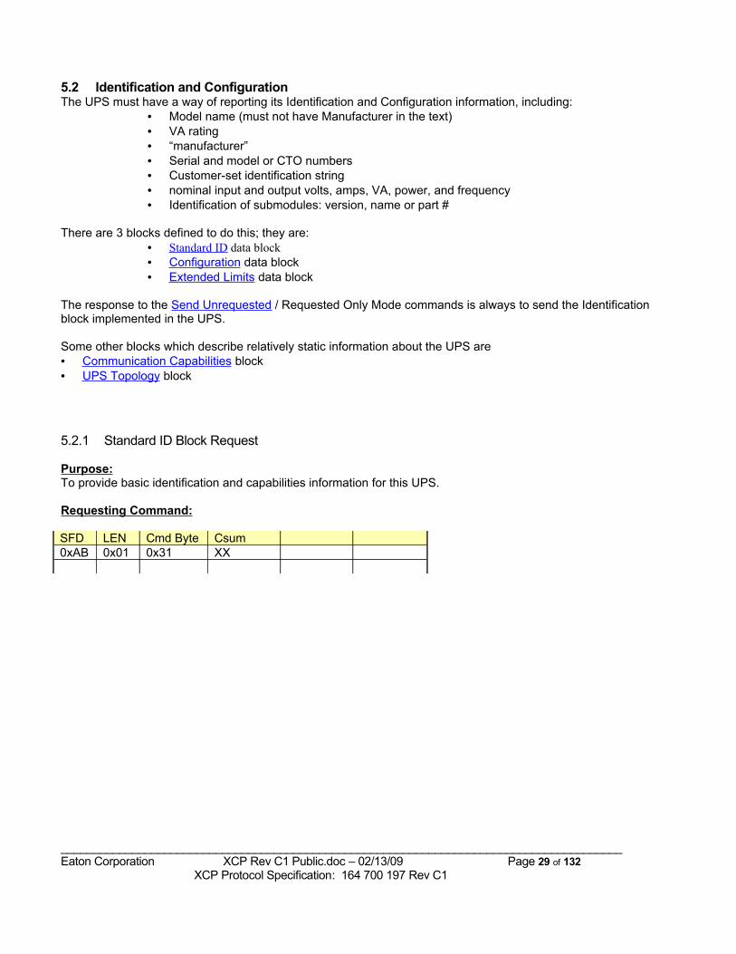
5.2.1 Standard ID Block Request
Purpose:To provide basic identification and capabilities information for this UPS.
Requesting Command:
SFD LEN Cmd Byte Csum0xAB 0x01 0x31 XX
_______________________________________________________________________________________Eaton Corporation XCP Rev C1 Public.doc – 02/13/09 Page 29 of 132 XCP Protocol Specification: 164 700 197 Rev C1
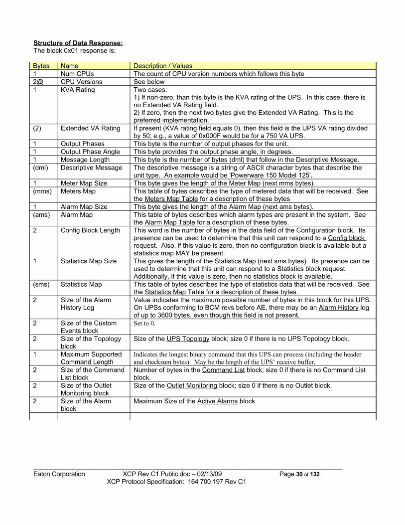
Structure of Data Response:The block 0x01 response is:
Bytes Name Description / Values1 Num CPUs The count of CPU version numbers which follows this byte2@ CPU Versions See below1 KVA Rating Two cases:
1) If non-zero, than this byte is the KVA rating of the UPS. In this case, there is no Extended VA Rating field.2) If zero, then the next two bytes give the Extended VA Rating. This is the preferred implementation.
(2) Extended VA Rating If present (KVA rating field equals 0), then this field is the UPS VA rating divided by 50; e.g., a value of 0x000F would be for a 750 VA UPS.
1 Output Phases This byte is the number of output phases for the unit.1 Output Phase Angle This byte provides the output phase angle, in degrees.1 Message Length This byte is the number of bytes (dml) that follow in the Descriptive Message.(dml) Descriptive Message The descriptive message is a string of ASCII character bytes that describe the
unit type. An example would be 'Powerware 150 Model 125'.1 Meter Map Size This byte gives the length of the Meter Map (next mms bytes).(mms) Meters Map This table of bytes describes the type of metered data that will be received. See
the Meters Map Table for a description of these bytes1 Alarm Map Size This byte gives the length of the Alarm Map (next ams bytes).(ams) Alarm Map This table of bytes describes which alarm types are present in the system. See
the Alarm Map Table for a description of these bytes.2 Config Block Length This word is the number of bytes in the data field of the Configuration block. Its
presence can be used to determine that this unit can respond to a Config block request. Also, if this value is zero, then no configuration block is available but a statistics map MAY be present.
1 Statistics Map Size This gives the length of the Statistics Map (next sms bytes). Its presence can be used to determine that this unit can respond to a Statistics block request. Additionally, if this value is zero, then no statistics block is available.
(sms) Statistics Map This table of bytes describes the type of statistics data that will be received. See the Sta tistics Map Table for a description of these bytes.
2 Size of the Alarm History Log
Value indicates the maximum possible number of bytes in this block for this UPS. On UPSs conforming to BCM revs before AE, there may be an Alarm History log of up to 3600 bytes, even though this field is not present.
2 Size of the Custom Events block
Set to 0.
2 Size of the Topology block
Size of the UPS Topology block; size 0 if there is no UPS Topology block.
1 Maximum Supported Command Length
Indicates the longest binary command that this UPS can process (including the header and checksum bytes). May be the length of the UPS’ receive buffer.
2 Size of the Command List block
Number of bytes in the Command List block; size 0 if there is no Command List block.
2 Size of the Outlet Monitoring block
Size of the Outlet Monitoring block; size 0 if there is no Outlet block.
2 Size of the Alarm block
Maximum Size of the Active Alarms block
_______________________________________________________________________________________Eaton Corporation XCP Rev C1 Public.doc – 02/13/09 Page 30 of 132 XCP Protocol Specification: 164 700 197 Rev C1
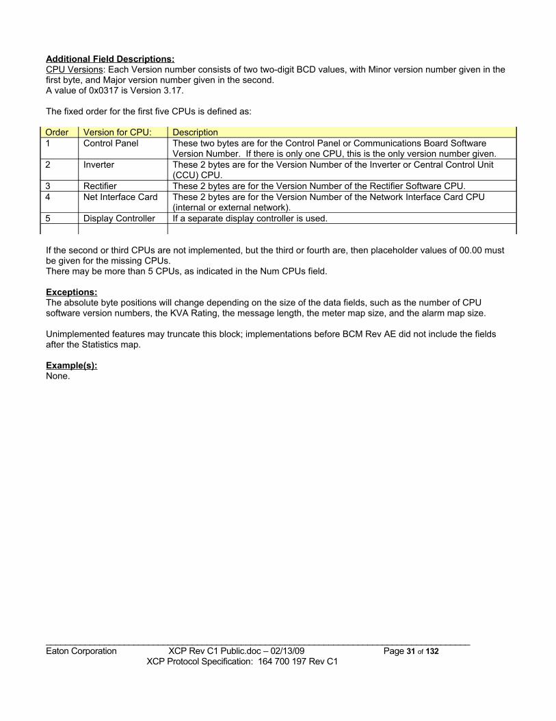
Additional Field Descriptions:CPU Versions: Each Version number consists of two two-digit BCD values, with Minor version number given in the first byte, and Major version number given in the second. A value of 0x0317 is Version 3.17.
The fixed order for the first five CPUs is defined as:
Order Version for CPU: Description1 Control Panel These two bytes are for the Control Panel or Communications Board Software
Version Number. If there is only one CPU, this is the only version number given.2 Inverter These 2 bytes are for the Version Number of the Inverter or Central Control Unit
(CCU) CPU.3 Rectifier These 2 bytes are for the Version Number of the Rectifier Software CPU.4 Net Interface Card These 2 bytes are for the Version Number of the Network Interface Card CPU
(internal or external network).5 Display Controller If a separate display controller is used.
If the second or third CPUs are not implemented, but the third or fourth are, then placeholder values of 00.00 must be given for the missing CPUs.There may be more than 5 CPUs, as indicated in the Num CPUs field.
Exceptions:The absolute byte positions will change depending on the size of the data fields, such as the number of CPU software version numbers, the KVA Rating, the message length, the meter map size, and the alarm map size.
Unimplemented features may truncate this block; implementations before BCM Rev AE did not include the fields after the Statistics map.
Example(s):None.
_______________________________________________________________________________________Eaton Corporation XCP Rev C1 Public.doc – 02/13/09 Page 31 of 132 XCP Protocol Specification: 164 700 197 Rev C1
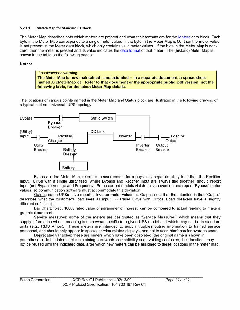
5.2.1.1 Meters Map for Standard ID Block
The Meter Map describes both which meters are present and what their formats are for the Meters data block. Each byte in the Meter Map corresponds to a single meter value. If the byte in the Meter Map is 00, then the meter value is not present in the Meter data block, which only contains valid meter values. If the byte in the Meter Map is non-zero, then the meter is present and its value indicates the data format of that meter. The (historic) Meter Map is shown in the table on the following pages.
Notes:
Obsolescence warningThe Meter Map is now maintained –and extended -- in a separate document, a spreadsheet named XcpMeterMap.xls. Refer to that document or the appropriate public .pdf version, not the following table, for the latest Meter Map details.
The locations of various points named in the Meter Map and Status block are illustrated in the following drawing of a typical, but not universal, UPS topology:
Bypass Static SwitchBypassBreaker
(Utility) DC LinkInput Rectifier/ Inverter Load or
Charger OutputUtility Inverter OutputBreaker Battery Breaker Breaker
Breaker
Battery
Bypass: in the Meter Map, refers to measurements for a physically separate utility feed than the Rectifier Input. UPSs with a single utility feed (where Bypass and Rectifier Input are always tied together) should report Input (not Bypass) Voltage and Frequency. Some current models violate this convention and report "Bypass" meter values, so communication software must accommodate this deviation.
Output: some UPSs have reported Inverter meter values as Output; note that the intention is that "Output" describes what the customer's load sees as input. (Parallel UPSs with Critical Load breakers have a slightly different definition).
Bar Chart: fixed, 100% rated value of parameter of interest; can be compared to actual reading to make a graphical bar chart.
Service measures: some of the meters are designated as “Service Measures”, which means that they supply information whose meaning is somewhat specific to a given UPS model and which may not be in standard units (e.g., RMS Amps). These meters are intended to supply troubleshooting information to trained service personnel, and should only appear in special service-related displays, and not in user interfaces for average users.
Deprecated variables: these are meters which have been obsoleted (the original name is shown in parentheses). In the interest of maintaining backwards compatibility and avoiding confusion, their locations may not be reused until the indicated date, after which new meters can be assigned to these locations in the meter map.
_______________________________________________________________________________________Eaton Corporation XCP Rev C1 Public.doc – 02/13/09 Page 32 of 132 XCP Protocol Specification: 164 700 197 Rev C1
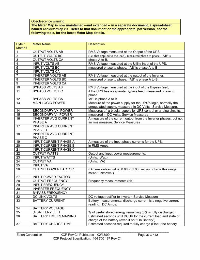
Obsolescence warningThe Meter Map is now maintained –and extended -- in a separate document, a spreadsheet named XcpMeterMap.xls. Refer to that document or the appropriate .pdf version, not the following table, for the latest Meter Map details.
Byte /Meter #
Meter Name Description
1 OUTPUT VOLTS AB RMS Voltage measured at the Output of the UPS 2 OUTPUT VOLTS BC (i.e. that applied to the load), measured phase to phase. 'AB' is3 OUTPUT VOLTS CA phase A to B.4 INPUT VOLTS AB RMS Voltage measured at the Utility Input of the UPS, 5 INPUT VOLTS BC measured phase to phase. 'AB' is phase A to B.6 INPUT VOLTS CA7 INVERTER VOLTS AB RMS Voltage measured at the output of the Inverter, 8 INVERTER VOLTS BC measured phase to phase. ‘AB’ is phase A to B.9 INVERTER VOLTS CA10 BYPASS VOLTS AB RMS Voltage measured at the input of the Bypass feed,11 BYPASS VOLTS BC if the UPS has a separate Bypass feed, measured phase to
phase.12 BYPASS VOLTS CA ‘AB’ is phase A to B.13 MAIN LOGIC POWER Measure of the power supply for the UPS’s logic, normally the
unregulated supply, measured in DC Volts. Service Measure.14 SECONDARY V+ POWER Measures of a bipolar supply for UPS control or analog circuits,15 SECONDARY V- POWER measured in DC Volts. Service Measures16 INVERTER AVG CURRENT
PHASE A A measure of the current output from the Inverter phases, but not an rms measure. Service Measures
17 INVERTER AVG CURRENT PHASE B
18 INVERTER AVG CURRENT PHASE C
19 INPUT CURRENT PHASE A A measure of the Input phase currents for the UPS, 20 INPUT CURRENT PHASE B in RMS Amps.21 INPUT CURRENT PHASE C 22 OUTPUT WATTS Output and input power measurements.23 INPUT WATTS (Units: Watt)24 OUTPUT VA (Units: VA)25 INPUT VA 26 OUTPUT POWER FACTOR (Dimensionless value, 0.00 to 1.00; values outside this range
mean “unknown”)27 INPUT POWER FACTOR 28 OUTPUT FREQUENCY Frequency measurements (Hz)29 INPUT FREQUENCY 30 INVERTER FREQUENCY 31 BYPASS FREQUENCY 32 DC LINK VOLTS DC voltage rectifier to inverter. Service Measure33 BATTERY CURRENT Battery measurements; discharge current is a negative current
reading. DC Amps.34 BATTERY VOLTAGE35 % BATTERY LEFT % of useful stored energy remaining (0% is fully discharged)36 BATTERY TIME REMAINING Estimated seconds until DCUV for the current load and state of
charge of the battery (even if not “On Battery”)37 BATTERY CHARGE TIME Estimated seconds required to fully charge (Float) the battery
_______________________________________________________________________________________Eaton Corporation XCP Rev C1 Public.doc – 02/13/09 Page 33 of 132 XCP Protocol Specification: 164 700 197 Rev C1
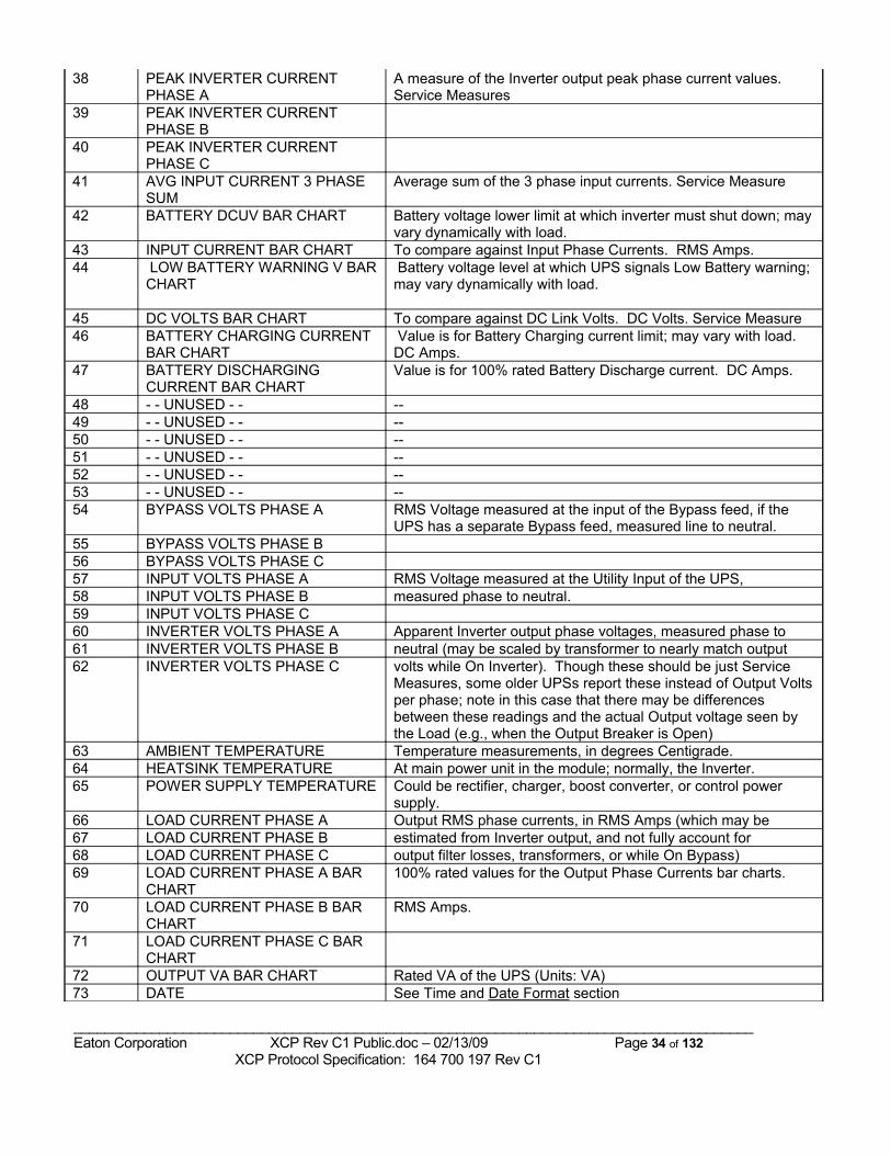
38 PEAK INVERTER CURRENT PHASE A
A measure of the Inverter output peak phase current values. Service Measures
39 PEAK INVERTER CURRENT PHASE B
40 PEAK INVERTER CURRENT PHASE C
41 AVG INPUT CURRENT 3 PHASE SUM
Average sum of the 3 phase input currents. Service Measure
42 BATTERY DCUV BAR CHART Battery voltage lower limit at which inverter must shut down; may vary dynamically with load.
43 INPUT CURRENT BAR CHART To compare against Input Phase Currents. RMS Amps.44 LOW BATTERY WARNING V BAR
CHART Battery voltage level at which UPS signals Low Battery warning; may vary dynamically with load.
45 DC VOLTS BAR CHART To compare against DC Link Volts. DC Volts. Service Measure 46 BATTERY CHARGING CURRENT
BAR CHART Value is for Battery Charging current limit; may vary with load. DC Amps.
47 BATTERY DISCHARGING CURRENT BAR CHART
Value is for 100% rated Battery Discharge current. DC Amps.
48 - - UNUSED - - --49 - - UNUSED - - --50 - - UNUSED - - --51 - - UNUSED - - --52 - - UNUSED - - --53 - - UNUSED - - --54 BYPASS VOLTS PHASE A RMS Voltage measured at the input of the Bypass feed, if the
UPS has a separate Bypass feed, measured line to neutral.55 BYPASS VOLTS PHASE B56 BYPASS VOLTS PHASE C57 INPUT VOLTS PHASE A RMS Voltage measured at the Utility Input of the UPS, 58 INPUT VOLTS PHASE B measured phase to neutral.59 INPUT VOLTS PHASE C 60 INVERTER VOLTS PHASE A Apparent Inverter output phase voltages, measured phase to61 INVERTER VOLTS PHASE B neutral (may be scaled by transformer to nearly match output62 INVERTER VOLTS PHASE C volts while On Inverter). Though these should be just Service
Measures, some older UPSs report these instead of Output Volts per phase; note in this case that there may be differences between these readings and the actual Output voltage seen by the Load (e.g., when the Output Breaker is Open)
63 AMBIENT TEMPERATURE Temperature measurements, in degrees Centigrade.64 HEATSINK TEMPERATURE At main power unit in the module; normally, the Inverter.65 POWER SUPPLY TEMPERATURE Could be rectifier, charger, boost converter, or control power
supply.66 LOAD CURRENT PHASE A Output RMS phase currents, in RMS Amps (which may be 67 LOAD CURRENT PHASE B estimated from Inverter output, and not fully account for68 LOAD CURRENT PHASE C output filter losses, transformers, or while On Bypass)69 LOAD CURRENT PHASE A BAR
CHART100% rated values for the Output Phase Currents bar charts.
70 LOAD CURRENT PHASE B BAR CHART
RMS Amps.
71 LOAD CURRENT PHASE C BAR CHART
72 OUTPUT VA BAR CHART Rated VA of the UPS (Units: VA)73 DATE See Time and Date Format section
_______________________________________________________________________________________Eaton Corporation XCP Rev C1 Public.doc – 02/13/09 Page 34 of 132 XCP Protocol Specification: 164 700 197 Rev C1
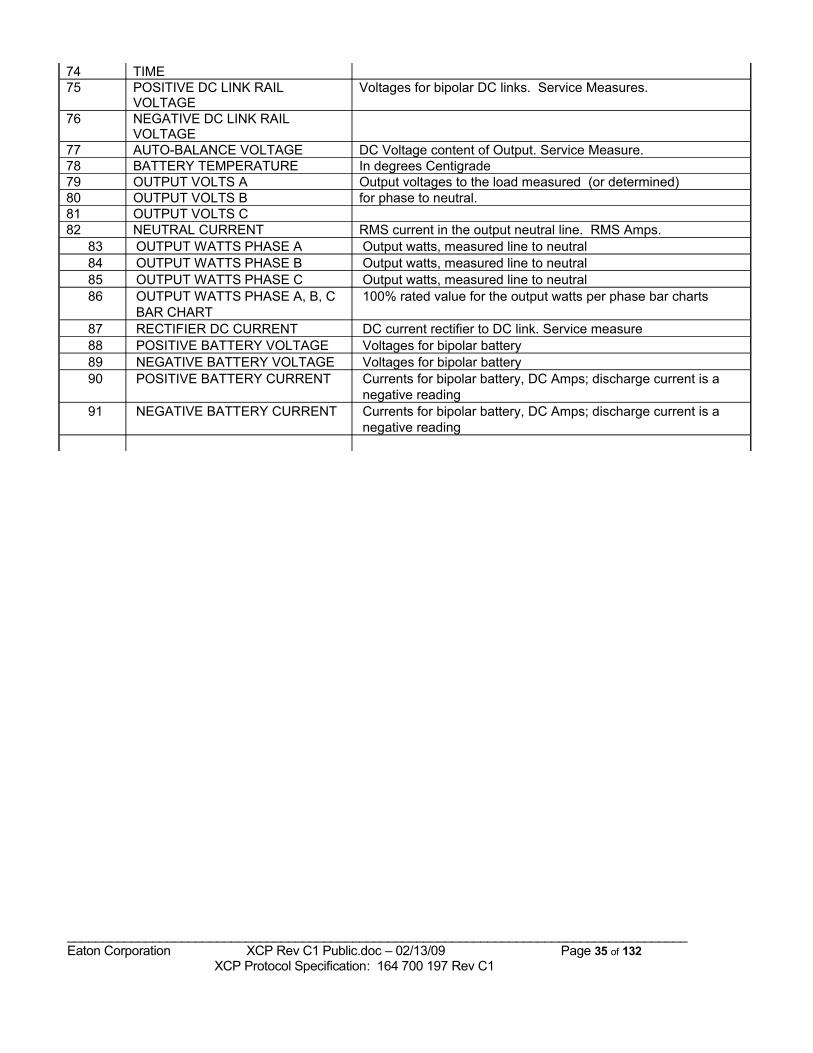
74 TIME75 POSITIVE DC LINK RAIL
VOLTAGEVoltages for bipolar DC links. Service Measures.
76 NEGATIVE DC LINK RAIL VOLTAGE
77 AUTO-BALANCE VOLTAGE DC Voltage content of Output. Service Measure.78 BATTERY TEMPERATURE In degrees Centigrade79 OUTPUT VOLTS A Output voltages to the load measured (or determined)80 OUTPUT VOLTS B for phase to neutral.81 OUTPUT VOLTS C 82 NEUTRAL CURRENT RMS current in the output neutral line. RMS Amps.
83 OUTPUT WATTS PHASE A Output watts, measured line to neutral84 OUTPUT WATTS PHASE B Output watts, measured line to neutral85 OUTPUT WATTS PHASE C Output watts, measured line to neutral86 OUTPUT WATTS PHASE A, B, C
BAR CHART100% rated value for the output watts per phase bar charts
87 RECTIFIER DC CURRENT DC current rectifier to DC link. Service measure88 POSITIVE BATTERY VOLTAGE Voltages for bipolar battery89 NEGATIVE BATTERY VOLTAGE Voltages for bipolar battery90 POSITIVE BATTERY CURRENT Currents for bipolar battery, DC Amps; discharge current is a
negative reading91 NEGATIVE BATTERY CURRENT Currents for bipolar battery, DC Amps; discharge current is a
negative reading
_______________________________________________________________________________________Eaton Corporation XCP Rev C1 Public.doc – 02/13/09 Page 35 of 132 XCP Protocol Specification: 164 700 197 Rev C1
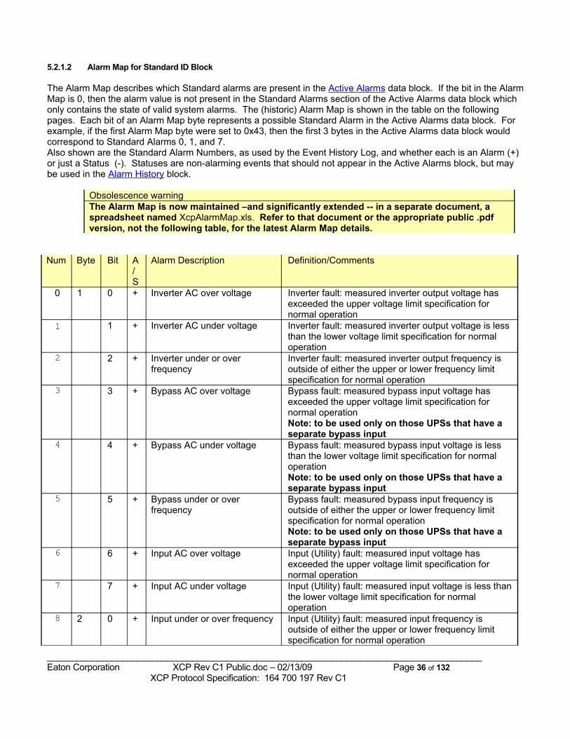
5.2.1.2 Alarm Map for Standard ID Block
The Alarm Map describes which Standard alarms are present in the Active Alarms data block. If the bit in the Alarm Map is 0, then the alarm value is not present in the Standard Alarms section of the Active Alarms data block which only contains the state of valid system alarms. The (historic) Alarm Map is shown in the table on the following pages. Each bit of an Alarm Map byte represents a possible Standard Alarm in the Active Alarms data block. For example, if the first Alarm Map byte were set to 0x43, then the first 3 bytes in the Active Alarms data block would correspond to Standard Alarms 0, 1, and 7. Also shown are the Standard Alarm Numbers, as used by the Event History Log, and whether each is an Alarm (+) or just a Status (-). Statuses are non-alarming events that should not appear in the Active Alarms block, but may be used in the Alarm History block.
Obsolescence warningThe Alarm Map is now maintained –and significantly extended -- in a separate document, a spreadsheet named XcpAlarmMap.xls. Refer to that document or the appropriate public .pdf version, not the following table, for the latest Alarm Map details.
Num Byte Bit A/S
Alarm Description Definition/Comments
0 1 0 + Inverter AC over voltage Inverter fault: measured inverter output voltage has exceeded the upper voltage limit specification for normal operation
1 1 + Inverter AC under voltage Inverter fault: measured inverter output voltage is less than the lower voltage limit specification for normal operation
2 2 + Inverter under or over frequency
Inverter fault: measured inverter output frequency is outside of either the upper or lower frequency limit specification for normal operation
3 3 + Bypass AC over voltage Bypass fault: measured bypass input voltage has exceeded the upper voltage limit specification for normal operationNote: to be used only on those UPSs that have a separate bypass input
4 4 + Bypass AC under voltage Bypass fault: measured bypass input voltage is less than the lower voltage limit specification for normal operationNote: to be used only on those UPSs that have a separate bypass input
5 5 + Bypass under or over frequency
Bypass fault: measured bypass input frequency is outside of either the upper or lower frequency limit specification for normal operationNote: to be used only on those UPSs that have a separate bypass input
6 6 + Input AC over voltage Input (Utility) fault: measured input voltage has exceeded the upper voltage limit specification for normal operation
7 7 + Input AC under voltage Input (Utility) fault: measured input voltage is less than the lower voltage limit specification for normal operation
8 2 0 + Input under or over frequency Input (Utility) fault: measured input frequency is outside of either the upper or lower frequency limit specification for normal operation
_______________________________________________________________________________________Eaton Corporation XCP Rev C1 Public.doc – 02/13/09 Page 36 of 132 XCP Protocol Specification: 164 700 197 Rev C1
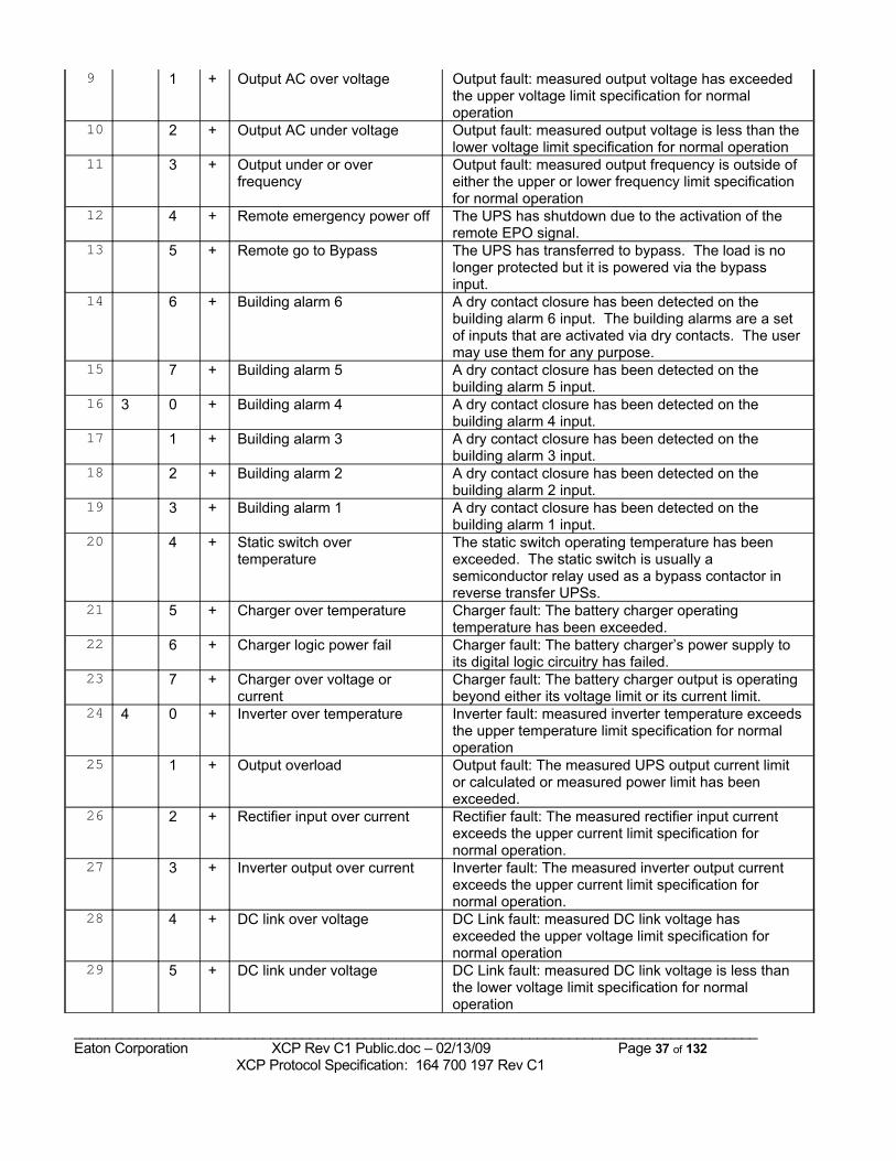
9 1 + Output AC over voltage Output fault: measured output voltage has exceeded the upper voltage limit specification for normal operation
10 2 + Output AC under voltage Output fault: measured output voltage is less than the lower voltage limit specification for normal operation
11 3 + Output under or over frequency
Output fault: measured output frequency is outside of either the upper or lower frequency limit specification for normal operation
12 4 + Remote emergency power off The UPS has shutdown due to the activation of the remote EPO signal.
13 5 + Remote go to Bypass The UPS has transferred to bypass. The load is no longer protected but it is powered via the bypass input.
14 6 + Building alarm 6 A dry contact closure has been detected on the building alarm 6 input. The building alarms are a set of inputs that are activated via dry contacts. The user may use them for any purpose.
15 7 + Building alarm 5 A dry contact closure has been detected on the building alarm 5 input.
16 3 0 + Building alarm 4 A dry contact closure has been detected on the building alarm 4 input.
17 1 + Building alarm 3 A dry contact closure has been detected on the building alarm 3 input.
18 2 + Building alarm 2 A dry contact closure has been detected on the building alarm 2 input.
19 3 + Building alarm 1 A dry contact closure has been detected on the building alarm 1 input.
20 4 + Static switch over temperature
The static switch operating temperature has been exceeded. The static switch is usually a semiconductor relay used as a bypass contactor in reverse transfer UPSs.
21 5 + Charger over temperature Charger fault: The battery charger operating temperature has been exceeded.
22 6 + Charger logic power fail Charger fault: The battery charger’s power supply to its digital logic circuitry has failed.
23 7 + Charger over voltage or current
Charger fault: The battery charger output is operating beyond either its voltage limit or its current limit.
24 4 0 + Inverter over temperature Inverter fault: measured inverter temperature exceeds the upper temperature limit specification for normal operation
25 1 + Output overload Output fault: The measured UPS output current limit or calculated or measured power limit has been exceeded.
26 2 + Rectifier input over current Rectifier fault: The measured rectifier input current exceeds the upper current limit specification for normal operation.
27 3 + Inverter output over current Inverter fault: The measured inverter output current exceeds the upper current limit specification for normal operation.
28 4 + DC link over voltage DC Link fault: measured DC link voltage has exceeded the upper voltage limit specification for normal operation
29 5 + DC link under voltage DC Link fault: measured DC link voltage is less than the lower voltage limit specification for normal operation
_______________________________________________________________________________________Eaton Corporation XCP Rev C1 Public.doc – 02/13/09 Page 37 of 132 XCP Protocol Specification: 164 700 197 Rev C1
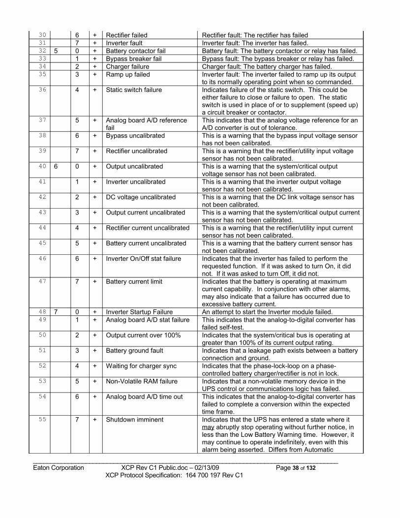
30 6 + Rectifier failed Rectifier fault: The rectifier has failed31 7 + Inverter fault Inverter fault: The inverter has failed.32 5 0 + Battery contactor fail Battery fault: The battery contactor or relay has failed.33 1 + Bypass breaker fail Bypass fault: The bypass breaker or relay has failed.34 2 + Charger failure Charger fault: The battery charger has failed.35 3 + Ramp up failed Inverter fault: The inverter failed to ramp up its output
to its normally operating point when so commanded.36 4 + Static switch failure Indicates failure of the static switch. This could be
either failure to close or failure to open. The static switch is used in place of or to supplement (speed up) a circuit breaker or contactor.
37 5 + Analog board A/D reference fail
This indicates that the analog voltage reference for an A/D converter is out of tolerance.
38 6 + Bypass uncalibrated This is a warning that the bypass input voltage sensor has not been calibrated.
39 7 + Rectifier uncalibrated This is a warning that the rectifier/utility input voltage sensor has not been calibrated.
40 6 0 + Output uncalibrated This is a warning that the system/critical output voltage sensor has not been calibrated.
41 1 + Inverter uncalibrated This is a warning that the inverter output voltage sensor has not been calibrated.
42 2 + DC voltage uncalibrated This is a warning that the DC link voltage sensor has not been calibrated.
43 3 + Output current uncalibrated This is a warning that the system/critical output current sensor has not been calibrated.
44 4 + Rectifier current uncalibrated This is a warning that the rectifier/utility input current sensor has not been calibrated.
45 5 + Battery current uncalibrated This is a warning that the battery current sensor has not been calibrated.
46 6 + Inverter On/Off stat failure Indicates that the inverter has failed to perform the requested function. If it was asked to turn On, it did not. If it was asked to turn Off, it did not.
47 7 + Battery current limit Indicates that the battery is operating at maximum current capability. In conjunction with other alarms, may also indicate that a failure has occurred due to excessive battery current.
48 7 0 + Inverter Startup Failure An attempt to start the Inverter module failed.49 1 + Analog board A/D stat failure This indicates that the analog-to-digital converter has
failed self-test. 50 2 + Output current over 100% Indicates that the system/critical bus is operating at
greater than 100% of its current output rating.51 3 + Battery ground fault Indicates that a leakage path exists between a battery
connection and ground.52 4 + Waiting for charger sync Indicates that the phase-lock-loop on a phase-
controlled battery charger/rectifier is not in lock.53 5 + Non-Volatile RAM failure Indicates that a non-volatile memory device in the
UPS control or communications logic has failed.54 6 + Analog board A/D time out This indicates that the analog-to-digital converter has
failed to complete a conversion within the expected time frame.
55 7 + Shutdown imminent Indicates that the UPS has entered a state where it may abruptly stop operating without further notice, in less than the Low Battery Warning time. However, it may continue to operate indefinitely, even with this alarm being asserted. Differs from Automatic
_______________________________________________________________________________________Eaton Corporation XCP Rev C1 Public.doc – 02/13/09 Page 38 of 132 XCP Protocol Specification: 164 700 197 Rev C1
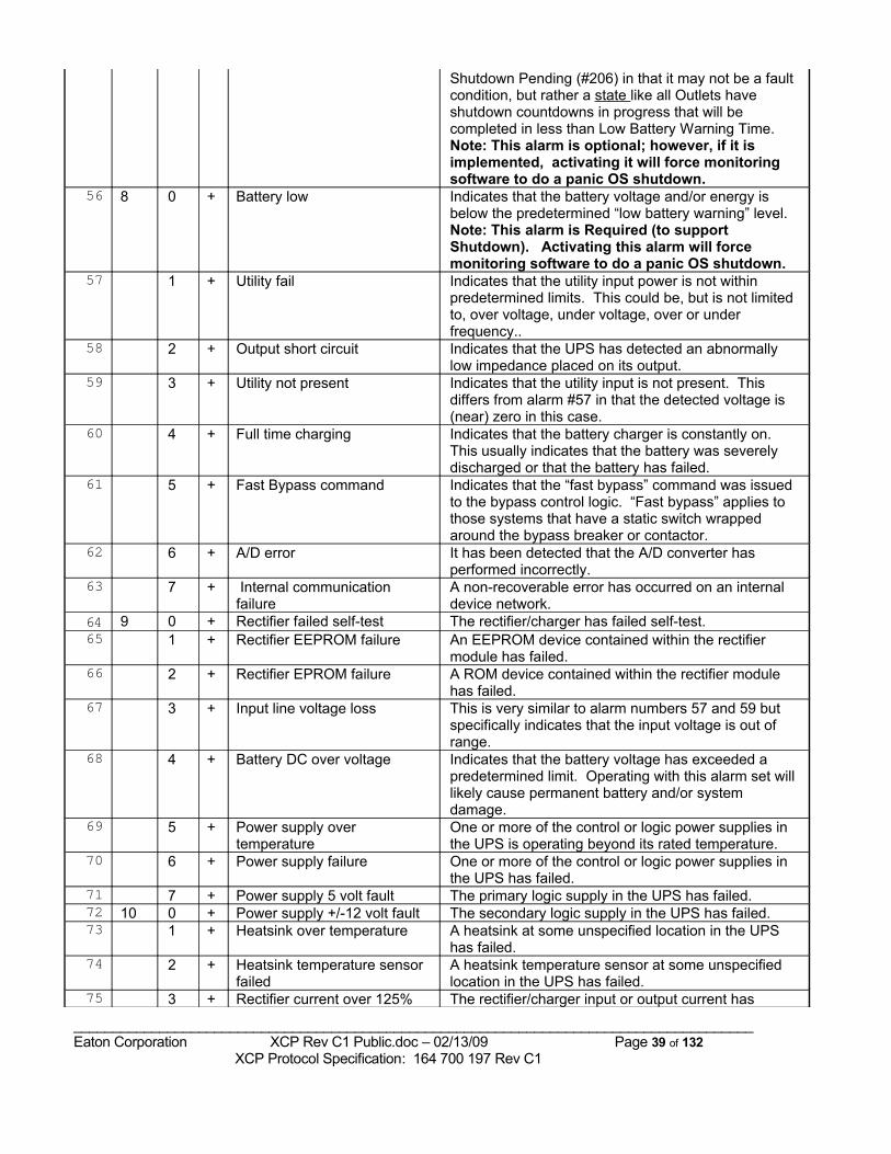
Shutdown Pending (#206) in that it may not be a fault condition, but rather a state like all Outlets have shutdown countdowns in progress that will be completed in less than Low Battery Warning Time.Note: This alarm is optional; however, if it is implemented, activating it will force monitoring software to do a panic OS shutdown.
56 8 0 + Battery low Indicates that the battery voltage and/or energy is below the predetermined “low battery warning” level.Note: This alarm is Required (to support Shutdown). Activating this alarm will force monitoring software to do a panic OS shutdown.
57 1 + Utility fail Indicates that the utility input power is not within predetermined limits. This could be, but is not limited to, over voltage, under voltage, over or under frequency..
58 2 + Output short circuit Indicates that the UPS has detected an abnormally low impedance placed on its output.
59 3 + Utility not present Indicates that the utility input is not present. This differs from alarm #57 in that the detected voltage is (near) zero in this case.
60 4 + Full time charging Indicates that the battery charger is constantly on. This usually indicates that the battery was severely discharged or that the battery has failed.
61 5 + Fast Bypass command Indicates that the “fast bypass” command was issued to the bypass control logic. “Fast bypass” applies to those systems that have a static switch wrapped around the bypass breaker or contactor.
62 6 + A/D error It has been detected that the A/D converter has performed incorrectly.
63 7 + Internal communication failure
A non-recoverable error has occurred on an internal device network.
64 9 0 + Rectifier failed self-test The rectifier/charger has failed self-test.65 1 + Rectifier EEPROM failure An EEPROM device contained within the rectifier
module has failed.66 2 + Rectifier EPROM failure A ROM device contained within the rectifier module
has failed.67 3 + Input line voltage loss This is very similar to alarm numbers 57 and 59 but
specifically indicates that the input voltage is out of range.
68 4 + Battery DC over voltage Indicates that the battery voltage has exceeded a predetermined limit. Operating with this alarm set will likely cause permanent battery and/or system damage.
69 5 + Power supply over temperature
One or more of the control or logic power supplies in the UPS is operating beyond its rated temperature.
70 6 + Power supply failure One or more of the control or logic power supplies in the UPS has failed.
71 7 + Power supply 5 volt fault The primary logic supply in the UPS has failed.72 10 0 + Power supply +/-12 volt fault The secondary logic supply in the UPS has failed.73 1 + Heatsink over temperature A heatsink at some unspecified location in the UPS
has failed.74 2 + Heatsink temperature sensor
failed A heatsink temperature sensor at some unspecified location in the UPS has failed.
75 3 + Rectifier current over 125% The rectifier/charger input or output current has
_______________________________________________________________________________________Eaton Corporation XCP Rev C1 Public.doc – 02/13/09 Page 39 of 132 XCP Protocol Specification: 164 700 197 Rev C1
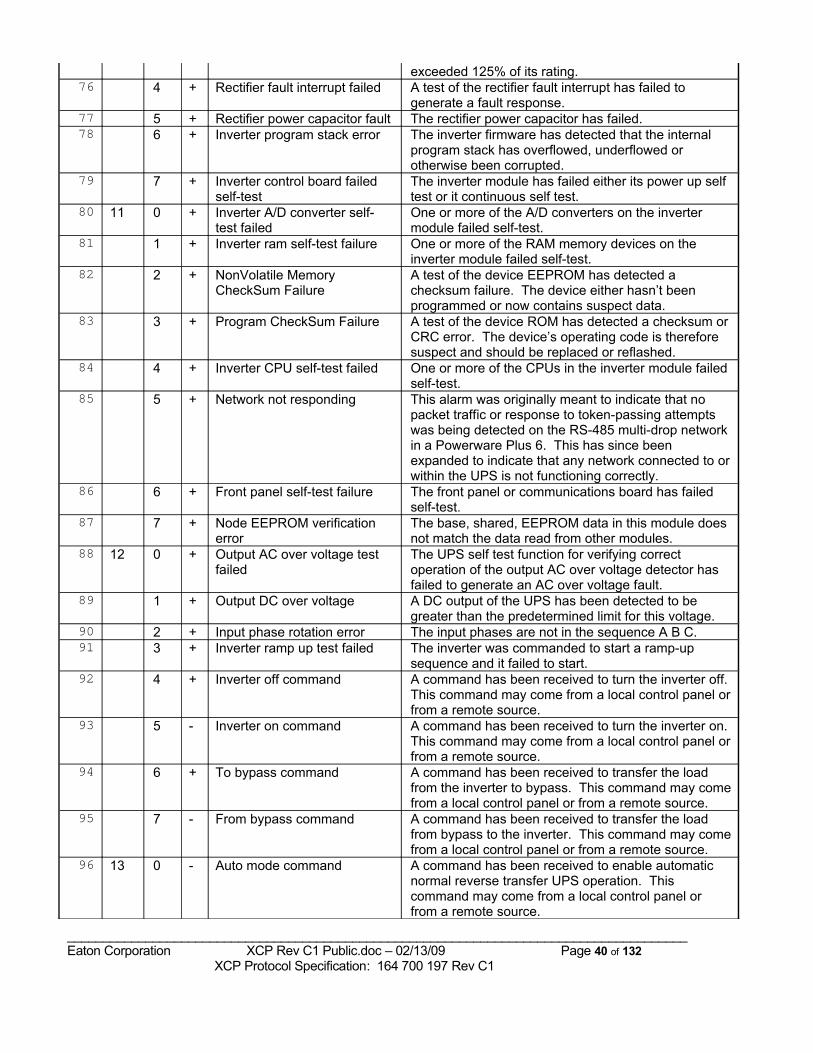
exceeded 125% of its rating.76 4 + Rectifier fault interrupt failed A test of the rectifier fault interrupt has failed to
generate a fault response.77 5 + Rectifier power capacitor fault The rectifier power capacitor has failed.78 6 + Inverter program stack error The inverter firmware has detected that the internal
program stack has overflowed, underflowed or otherwise been corrupted.
79 7 + Inverter control board failed self-test
The inverter module has failed either its power up self test or it continuous self test.
80 11 0 + Inverter A/D converter self-test failed
One or more of the A/D converters on the inverter module failed self-test.
81 1 + Inverter ram self-test failure One or more of the RAM memory devices on the inverter module failed self-test.
82 2 + NonVolatile Memory CheckSum Failure
A test of the device EEPROM has detected a checksum failure. The device either hasn’t been programmed or now contains suspect data.
83 3 + Program CheckSum Failure A test of the device ROM has detected a checksum or CRC error. The device’s operating code is therefore suspect and should be replaced or reflashed.
84 4 + Inverter CPU self-test failed One or more of the CPUs in the inverter module failed self-test.
85 5 + Network not responding This alarm was originally meant to indicate that no packet traffic or response to token-passing attempts was being detected on the RS-485 multi-drop network in a Powerware Plus 6. This has since been expanded to indicate that any network connected to or within the UPS is not functioning correctly.
86 6 + Front panel self-test failure The front panel or communications board has failed self-test.
87 7 + Node EEPROM verification error
The base, shared, EEPROM data in this module does not match the data read from other modules.
88 12 0 + Output AC over voltage test failed
The UPS self test function for verifying correct operation of the output AC over voltage detector has failed to generate an AC over voltage fault.
89 1 + Output DC over voltage A DC output of the UPS has been detected to be greater than the predetermined limit for this voltage.
90 2 + Input phase rotation error The input phases are not in the sequence A B C.91 3 + Inverter ramp up test failed The inverter was commanded to start a ramp-up
sequence and it failed to start.92 4 + Inverter off command A command has been received to turn the inverter off.
This command may come from a local control panel or from a remote source.
93 5 - Inverter on command A command has been received to turn the inverter on. This command may come from a local control panel or from a remote source.
94 6 + To bypass command A command has been received to transfer the load from the inverter to bypass. This command may come from a local control panel or from a remote source.
95 7 - From bypass command A command has been received to transfer the load from bypass to the inverter. This command may come from a local control panel or from a remote source.
96 13 0 - Auto mode command A command has been received to enable automatic normal reverse transfer UPS operation. This command may come from a local control panel or from a remote source.
_______________________________________________________________________________________Eaton Corporation XCP Rev C1 Public.doc – 02/13/09 Page 40 of 132 XCP Protocol Specification: 164 700 197 Rev C1
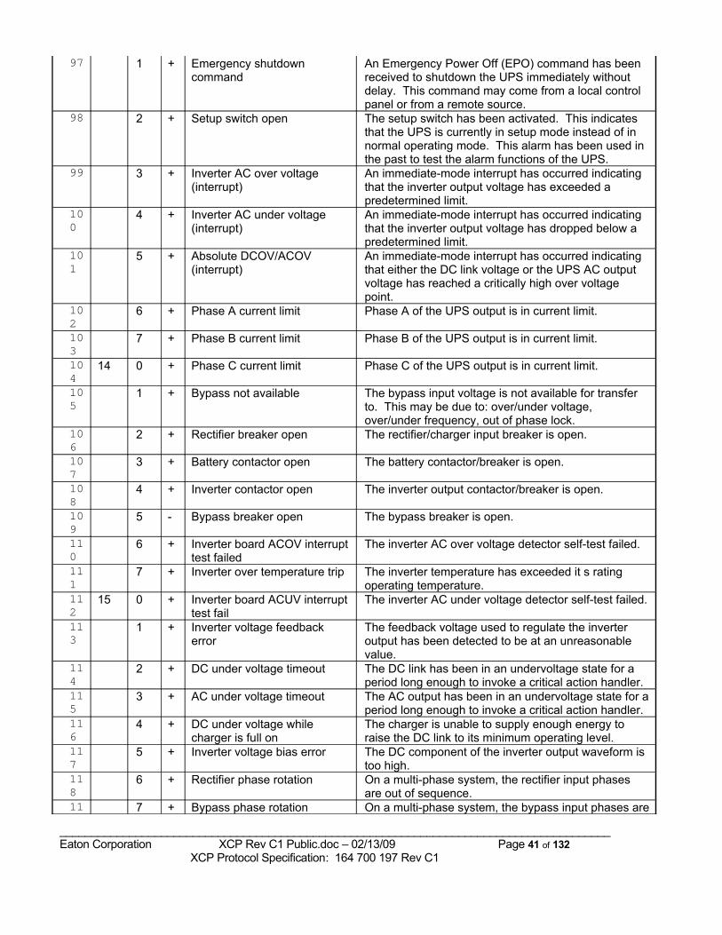
97 1 + Emergency shutdown command
An Emergency Power Off (EPO) command has been received to shutdown the UPS immediately without delay. This command may come from a local control panel or from a remote source.
98 2 + Setup switch open The setup switch has been activated. This indicates that the UPS is currently in setup mode instead of in normal operating mode. This alarm has been used in the past to test the alarm functions of the UPS.
99 3 + Inverter AC over voltage (interrupt)
An immediate-mode interrupt has occurred indicating that the inverter output voltage has exceeded a predetermined limit.
100
4 + Inverter AC under voltage (interrupt)
An immediate-mode interrupt has occurred indicating that the inverter output voltage has dropped below a predetermined limit.
101
5 + Absolute DCOV/ACOV (interrupt)
An immediate-mode interrupt has occurred indicating that either the DC link voltage or the UPS AC output voltage has reached a critically high over voltage point.
102
6 + Phase A current limit Phase A of the UPS output is in current limit.
103
7 + Phase B current limit Phase B of the UPS output is in current limit.
104
14 0 + Phase C current limit Phase C of the UPS output is in current limit.
105
1 + Bypass not available The bypass input voltage is not available for transfer to. This may be due to: over/under voltage, over/under frequency, out of phase lock.
106
2 + Rectifier breaker open The rectifier/charger input breaker is open.
107
3 + Battery contactor open The battery contactor/breaker is open.
108
4 + Inverter contactor open The inverter output contactor/breaker is open.
109
5 - Bypass breaker open The bypass breaker is open.
110
6 + Inverter board ACOV interrupt test failed
The inverter AC over voltage detector self-test failed.
111
7 + Inverter over temperature trip The inverter temperature has exceeded it s rating operating temperature.
112
15 0 + Inverter board ACUV interrupt test fail
The inverter AC under voltage detector self-test failed.
113
1 + Inverter voltage feedback error
The feedback voltage used to regulate the inverter output has been detected to be at an unreasonable value.
114
2 + DC under voltage timeout The DC link has been in an undervoltage state for a period long enough to invoke a critical action handler.
115
3 + AC under voltage timeout The AC output has been in an undervoltage state for a period long enough to invoke a critical action handler.
116
4 + DC under voltage while charger is full on
The charger is unable to supply enough energy to raise the DC link to its minimum operating level.
117
5 + Inverter voltage bias error The DC component of the inverter output waveform is too high.
118
6 + Rectifier phase rotation On a multi-phase system, the rectifier input phases are out of sequence.
11 7 + Bypass phase rotation On a multi-phase system, the bypass input phases are
_______________________________________________________________________________________Eaton Corporation XCP Rev C1 Public.doc – 02/13/09 Page 41 of 132 XCP Protocol Specification: 164 700 197 Rev C1
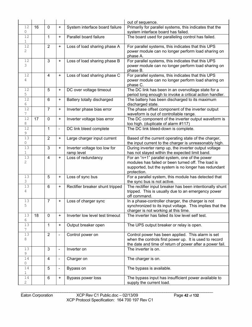
out of sequence.120
16 0 + System interface board failure Primarily for parallel systems, this indicates that the system interface board has failed.
121
1 + Parallel board failure The board used for paralleling control has failed.
122
2 + Loss of load sharing phase A For parallel systems, this indicates that this UPS power module can no longer perform load sharing on phase A.
123
3 + Loss of load sharing phase B For parallel systems, this indicates that this UPS power module can no longer perform load sharing on phase B.
124
4 + Loss of load sharing phase C For parallel systems, this indicates that this UPS power module can no longer perform load sharing on phase C.
125
5 + DC over voltage timeout The DC link has been in an overvoltage state for a period long enough to invoke a critical action handler.
126
6 + Battery totally discharged The battery has been discharged to its maximum discharged state.
127
7 + Inverter phase bias error The phase offset component of the inverter output waveform is out of controllable range.
128
17 0 + Inverter voltage bias error The DC component of the inverter output waveform is too high. (duplicate of alarm #117)
129
1 - DC link bleed complete The DC link bleed-down is complete.
130
2 + Large charger input current Based of the current operating state of the charger, the input current to the charger is unreasonably high.
131
3 + Inverter voltage too low for ramp level
During inverter ramp up, the inverter output voltage has not stayed within the expected limit band.
132
4 + Loss of redundancy For an “n+1” parallel system, one of the power modules has failed or been turned off. The load is supported, but the system is no longer has redundant protection.
133
5 + Loss of sync bus For a parallel system, this module has detected that the sync bus is not active.
134
6 + Rectifier breaker shunt tripped The rectifier input breaker has been intentionally shunt tripped. This is usually due to an emergency power off command.
135
7 + Loss of charger sync In a phase-controller charger, the charger is not synchronized to its input voltage. This implies that the charger is not working at this time.
136
18 0 + Inverter low level test timeout The inverter has failed its low level self test.
137
1 + Output breaker open The UPS output breaker or relay is open.
138
2 - Control power on Control power has been applied. This alarm is set when the controls first power up. It is used to record the date and time of return of power after a power fail.
139
3 - Inverter on The inverter is on.
140
4 - Charger on The charger is on.
141
5 - Bypass on The bypass is available.
142
6 + Bypass power loss The bypass input has insufficient power available to supply the current load.
_______________________________________________________________________________________Eaton Corporation XCP Rev C1 Public.doc – 02/13/09 Page 42 of 132 XCP Protocol Specification: 164 700 197 Rev C1
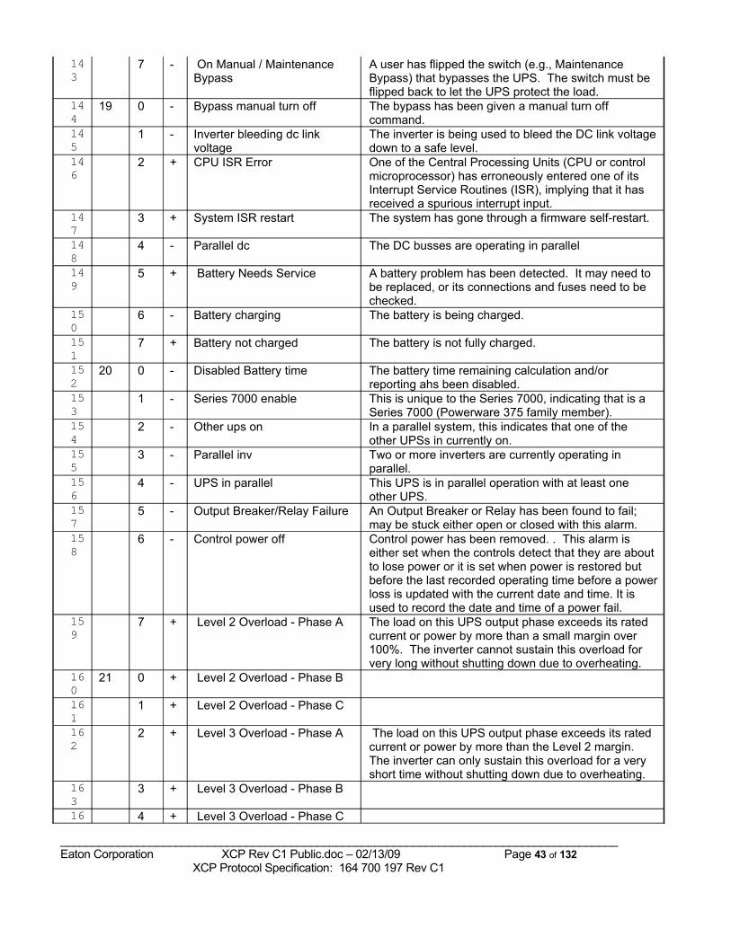
143
7 - On Manual / Maintenance Bypass
A user has flipped the switch (e.g., Maintenance Bypass) that bypasses the UPS. The switch must be flipped back to let the UPS protect the load.
144
19 0 - Bypass manual turn off The bypass has been given a manual turn off command.
145
1 - Inverter bleeding dc link voltage
The inverter is being used to bleed the DC link voltage down to a safe level.
146
2 + CPU ISR Error One of the Central Processing Units (CPU or control microprocessor) has erroneously entered one of its Interrupt Service Routines (ISR), implying that it has received a spurious interrupt input.
147
3 + System ISR restart The system has gone through a firmware self-restart.
148
4 - Parallel dc The DC busses are operating in parallel
149
5 + Battery Needs Service A battery problem has been detected. It may need to be replaced, or its connections and fuses need to be checked.
150
6 - Battery charging The battery is being charged.
151
7 + Battery not charged The battery is not fully charged.
152
20 0 - Disabled Battery time The battery time remaining calculation and/or reporting ahs been disabled.
153
1 - Series 7000 enable This is unique to the Series 7000, indicating that is a Series 7000 (Powerware 375 family member).
154
2 - Other ups on In a parallel system, this indicates that one of the other UPSs in currently on.
155
3 - Parallel inv Two or more inverters are currently operating in parallel.
156
4 - UPS in parallel This UPS is in parallel operation with at least one other UPS.
157
5 - Output Breaker/Relay Failure An Output Breaker or Relay has been found to fail; may be stuck either open or closed with this alarm.
158
6 - Control power off Control power has been removed. . This alarm is either set when the controls detect that they are about to lose power or it is set when power is restored but before the last recorded operating time before a power loss is updated with the current date and time. It is used to record the date and time of a power fail.
159
7 + Level 2 Overload - Phase A The load on this UPS output phase exceeds its rated current or power by more than a small margin over 100%. The inverter cannot sustain this overload for very long without shutting down due to overheating.
160
21 0 + Level 2 Overload - Phase B
161
1 + Level 2 Overload - Phase C
162
2 + Level 3 Overload - Phase A The load on this UPS output phase exceeds its rated current or power by more than the Level 2 margin. The inverter can only sustain this overload for a very short time without shutting down due to overheating.
163
3 + Level 3 Overload - Phase B
16 4 + Level 3 Overload - Phase C
_______________________________________________________________________________________Eaton Corporation XCP Rev C1 Public.doc – 02/13/09 Page 43 of 132 XCP Protocol Specification: 164 700 197 Rev C1
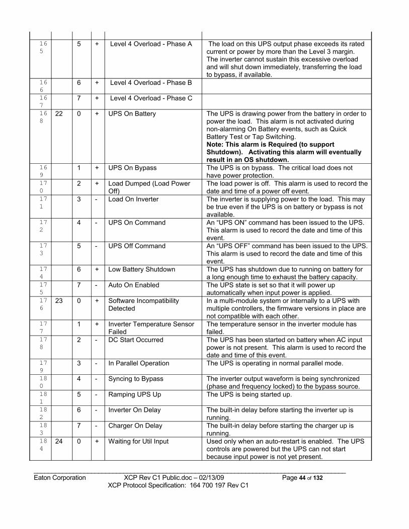
165
5 + Level 4 Overload - Phase A The load on this UPS output phase exceeds its rated current or power by more than the Level 3 margin. The inverter cannot sustain this excessive overload and will shut down immediately, transferring the load to bypass, if available.
166
6 + Level 4 Overload - Phase B
167
7 + Level 4 Overload - Phase C
168
22 0 + UPS On Battery The UPS is drawing power from the battery in order to power the load. This alarm is not activated during non-alarming On Battery events, such as Quick Battery Test or Tap Switching.Note: This alarm is Required (to support Shutdown). Activating this alarm will eventually result in an OS shutdown.
169
1 + UPS On Bypass The UPS is on bypass. The critical load does not have power protection.
170
2 + Load Dumped (Load Power Off)
The load power is off. This alarm is used to record the date and time of a power off event.
171
3 - Load On Inverter The inverter is supplying power to the load. This may be true even if the UPS is on battery or bypass is not available.
172
4 - UPS On Command An “UPS ON” command has been issued to the UPS. This alarm is used to record the date and time of this event.
173
5 - UPS Off Command An “UPS OFF” command has been issued to the UPS. This alarm is used to record the date and time of this event.
174
6 + Low Battery Shutdown The UPS has shutdown due to running on battery for a long enough time to exhaust the battery capacity.
175
7 - Auto On Enabled The UPS state is set so that it will power up automatically when input power is applied.
176
23 0 + Software Incompatibility Detected
In a multi-module system or internally to a UPS with multiple controllers, the firmware versions in place are not compatible with each other.
177
1 + Inverter Temperature Sensor Failed
The temperature sensor in the inverter module has failed.
178
2 - DC Start Occurred The UPS has been started on battery when AC input power is not present. This alarm is used to record the date and time of this event.
179
3 - In Parallel Operation The UPS is operating in normal parallel mode.
180
4 - Syncing to Bypass The inverter output waveform is being synchronized (phase and frequency locked) to the bypass source.
181
5 - Ramping UPS Up The UPS is being started up.
182
6 - Inverter On Delay The built-in delay before starting the inverter up is running.
183
7 - Charger On Delay The built-in delay before starting the charger up is running.
184
24 0 + Waiting for Util Input Used only when an auto-restart is enabled. The UPS controls are powered but the UPS can not start because input power is not yet present.
_______________________________________________________________________________________Eaton Corporation XCP Rev C1 Public.doc – 02/13/09 Page 44 of 132 XCP Protocol Specification: 164 700 197 Rev C1
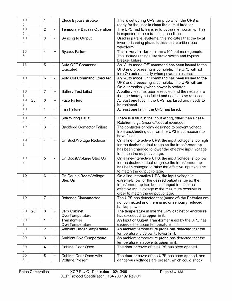
185
1 - Close Bypass Breaker This is set during UPS ramp up when the UPS is ready for the user to close the output breaker.
186
2 - Temporary Bypass Operation The UPS had to transfer to bypass temporarily. This is expected to be a transient condition.
187
3 - Syncing to Output Used in parallel systems, this indicates that the local inverter is being phase locked to the critical bus waveform.
188
4 + Bypass Failure This is very similar to alarm #105 but more generic. This includes things like static switch and bypass breaker failure.
189
5 + Auto OFF Command Executed
An “Auto mode Off” command has been issued to the UPS and processing is complete. The UPS will not turn On automatically when power is restored.
190
6 - Auto ON Command Executed An “Auto mode On” command has been issued to the UPS and processing is complete. The UPS will turn On automatically when power is restored.
191
7 + Battery Test failed A battery test has been executed and the results are that the battery has failed and needs to be replaced.
192
25 0 + Fuse Failure At least one fuse in the UPS has failed and needs to be replaced.
193
1 + Fan Failure At least one fan in the UPS has failed.
194
2 + Site Wiring Fault There is a fault in the input wiring, other than Phase Rotation; e.g., Ground/Neutral reversed.
195
3 + Backfeed Contactor Failure The contactor or relay designed to prevent voltage from backfeeding out from the UPS input appears to have failed.
196
4 - On Buck/Voltage Reducer On a line-interactive UPS, the input voltage is too high for the desired output range so the transformer tap has been changed to lower the effective input voltage to match the output voltage.
197
5 - On Boost/Voltage Step Up On a line-interactive UPS, the input voltage is too low for the desired output range so the transformer tap has been changed to raise the effective input voltage to match the output voltage.
198
6 - On Double Boost/Voltage Step Up
On a line-interactive UPS, the input voltage is extremely low for the desired output range so the transformer tap has been changed to raise the effective input voltage to the maximum possible in order to match the output voltage.
199
7 + Batteries Disconnected The UPS has detected that (some of) the Batteries are not connected and there is no or seriously reduced backup power.
200
26 0 + UPS Cabinet OverTemperature
The temperature inside the UPS cabinet or enclosure has exceeded its upper limit.
201
1 + Transformer OverTemperature
An Input or Output Transformer used by the UPS has exceeded its upper temperature limit.
202
2 + Ambient UnderTemperature An ambient temperature probe has detected that the temperature is below its lower limit.
203
3 + Ambient OverTemperature An ambient temperature probe has detected that the temperature is above its upper limit.
204
4 + Cabinet Door Open The door or cover of the UPS has been opened.
205
5 + Cabinet Door Open with Voltage Present
The door or cover of the UPS has been opened, and dangerous voltages are present which could shock
_______________________________________________________________________________________Eaton Corporation XCP Rev C1 Public.doc – 02/13/09 Page 45 of 132 XCP Protocol Specification: 164 700 197 Rev C1
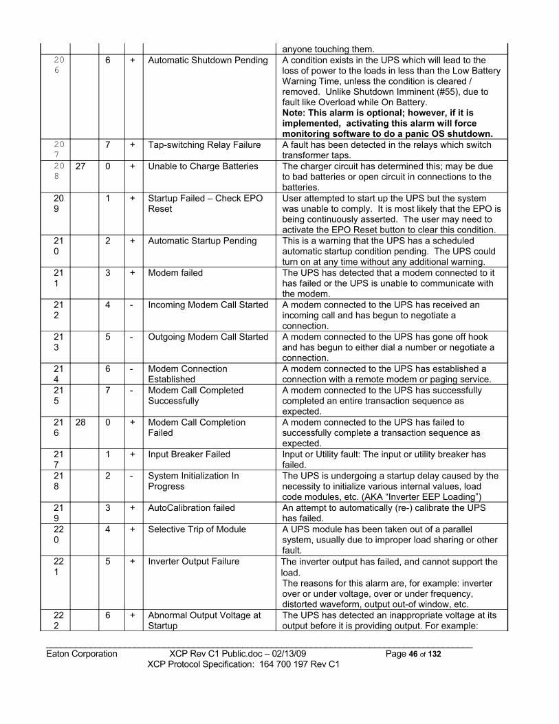
anyone touching them.206
6 + Automatic Shutdown Pending A condition exists in the UPS which will lead to the loss of power to the loads in less than the Low Battery Warning Time, unless the condition is cleared / removed. Unlike Shutdown Imminent (#55), due to fault like Overload while On Battery.Note: This alarm is optional; however, if it is implemented, activating this alarm will force monitoring software to do a panic OS shutdown.
207
7 + Tap-switching Relay Failure A fault has been detected in the relays which switch transformer taps.
208
27 0 + Unable to Charge Batteries The charger circuit has determined this; may be due to bad batteries or open circuit in connections to the batteries.
209
1 + Startup Failed – Check EPO Reset
User attempted to start up the UPS but the system was unable to comply. It is most likely that the EPO is being continuously asserted. The user may need to activate the EPO Reset button to clear this condition.
210
2 + Automatic Startup Pending This is a warning that the UPS has a scheduled automatic startup condition pending. The UPS could turn on at any time without any additional warning.
211
3 + Modem failed The UPS has detected that a modem connected to it has failed or the UPS is unable to communicate with the modem.
212
4 - Incoming Modem Call Started A modem connected to the UPS has received an incoming call and has begun to negotiate a connection.
213
5 - Outgoing Modem Call Started A modem connected to the UPS has gone off hook and has begun to either dial a number or negotiate a connection.
214
6 - Modem Connection Established
A modem connected to the UPS has established a connection with a remote modem or paging service.
215
7 - Modem Call Completed Successfully
A modem connected to the UPS has successfully completed an entire transaction sequence as expected.
216
28 0 + Modem Call Completion Failed
A modem connected to the UPS has failed to successfully complete a transaction sequence as expected.
217
1 + Input Breaker Failed Input or Utility fault: The input or utility breaker has failed.
218
2 - System Initialization In Progress
The UPS is undergoing a startup delay caused by the necessity to initialize various internal values, load code modules, etc. (AKA “Inverter EEP Loading”)
219
3 + AutoCalibration failed An attempt to automatically (re-) calibrate the UPS has failed.
220
4 + Selective Trip of Module A UPS module has been taken out of a parallel system, usually due to improper load sharing or other fault.
221
5 + Inverter Output Failure The inverter output has failed, and cannot support the load.The reasons for this alarm are, for example: inverter over or under voltage, over or under frequency, distorted waveform, output out-of window, etc.
222
6 + Abnormal Output Voltage at Startup
The UPS has detected an inappropriate voltage at its output before it is providing output. For example:
_______________________________________________________________________________________Eaton Corporation XCP Rev C1 Public.doc – 02/13/09 Page 46 of 132 XCP Protocol Specification: 164 700 197 Rev C1
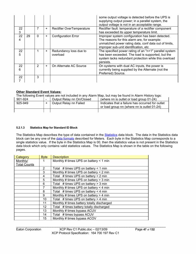
some output voltage is detected before the UPS is supplying output power; in a parallel system, the output voltage is not in an acceptable range.
223
7 + Rectifier OverTemperature Rectifier fault: temperature of a rectifier component has exceeded its upper temperature limit.
224
29 0 + Configuration Error Improper system configuration has been detected. The reasons for this alarm are, for example: unmatched power rating data, conf data out of limits, improper sub-unit identification, etc
225
1 + Redundancy loss due to overload
The specified power rating of an "n+1" parallel system has been exceeded. The load is supported, but the system lacks redundant protection while this overload persists.
226
2 + On Alternate AC Source On systems with dual AC inputs, the power is currently being supplied by the Alternate (not the Preferred) Source.
227
3
Other Standard Event Values:The following Event values are not included in any Alarm Map, but may be found in Alarm History logs:901-924 - Output Relay nn On/Closed (where nn is outlet or load group 01-24)925-949 + Output Relay nn Failed Indicates that a failure has occurred for outlet
or load group nn (where nn is outlet 01-24)
5.2.1.3 Statistics Map for Standard ID Block
The Statistics Map describes the type of data contained in the Statistics data block. The data in the Statistics data block can be any one of the data formats described for Meters. Each byte in the Statistics Map corresponds to a single statistics value. If the byte in the Statistics Map is 00, then the statistics value is not present in the Statistics data block which only contains valid statistics values. The Statistics Map is shown in the table on the following pages.
Category Byte DescriptionMonthly/Total Counts
1 Monthly # times UPS on battery < 1 min
2 Total # times UPS on battery < 1 min 3 Monthly # times UPS on battery < 2 min 4 Total # times UPS on battery < 2 min 5 Monthly # times UPS on battery > 3 min 6 Total # times UPS on battery > 3 min 7 Monthly # times UPS on battery < 4 min 8 Total # times UPS on battery < 4 min 9 Monthly # times UPS on battery > 4 min 10 Total # times UPS on battery > 4 min 11 Monthly # times battery totally discharged 12 Total # times battery totally discharged 13 Monthly # times bypass ACUV 14 Total # times bypass ACUV 15 Monthly # times bypass ACOV
_______________________________________________________________________________________Eaton Corporation XCP Rev C1 Public.doc – 02/13/09 Page 47 of 132 XCP Protocol Specification: 164 700 197 Rev C1
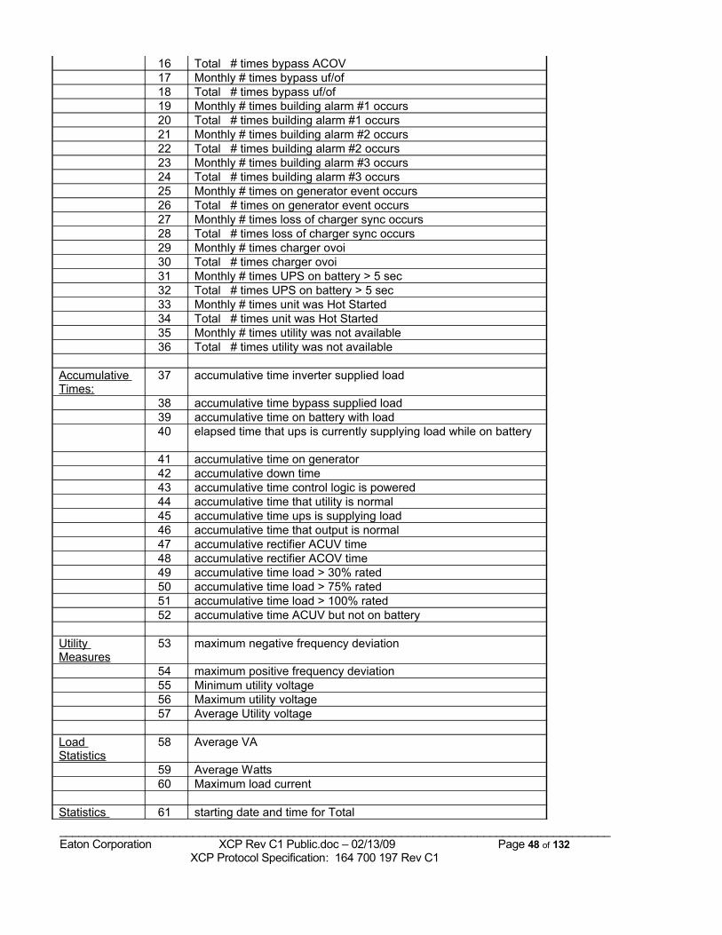
16 Total # times bypass ACOV 17 Monthly # times bypass uf/of 18 Total # times bypass uf/of 19 Monthly # times building alarm #1 occurs 20 Total # times building alarm #1 occurs 21 Monthly # times building alarm #2 occurs 22 Total # times building alarm #2 occurs 23 Monthly # times building alarm #3 occurs 24 Total # times building alarm #3 occurs 25 Monthly # times on generator event occurs 26 Total # times on generator event occurs 27 Monthly # times loss of charger sync occurs 28 Total # times loss of charger sync occurs 29 Monthly # times charger ovoi 30 Total # times charger ovoi 31 Monthly # times UPS on battery > 5 sec 32 Total # times UPS on battery > 5 sec 33 Monthly # times unit was Hot Started 34 Total # times unit was Hot Started 35 Monthly # times utility was not available 36 Total # times utility was not available
Accumulative Times:
37 accumulative time inverter supplied load
38 accumulative time bypass supplied load 39 accumulative time on battery with load 40 elapsed time that ups is currently supplying load while on battery
41 accumulative time on generator 42 accumulative down time 43 accumulative time control logic is powered 44 accumulative time that utility is normal 45 accumulative time ups is supplying load 46 accumulative time that output is normal 47 accumulative rectifier ACUV time 48 accumulative rectifier ACOV time 49 accumulative time load > 30% rated 50 accumulative time load > 75% rated 51 accumulative time load > 100% rated 52 accumulative time ACUV but not on battery
Utility Measures
53 maximum negative frequency deviation
54 maximum positive frequency deviation 55 Minimum utility voltage 56 Maximum utility voltage 57 Average Utility voltage
Load Statistics
58 Average VA
59 Average Watts 60 Maximum load current
Statistics 61 starting date and time for Total _______________________________________________________________________________________Eaton Corporation XCP Rev C1 Public.doc – 02/13/09 Page 48 of 132 XCP Protocol Specification: 164 700 197 Rev C1
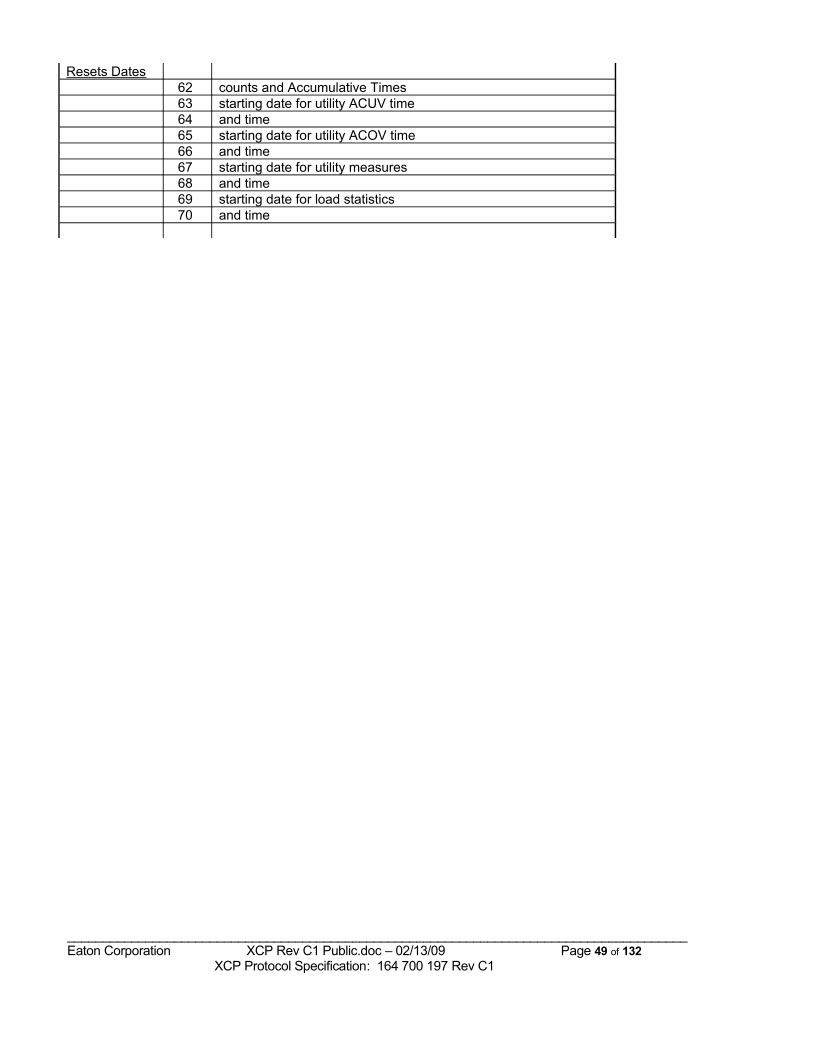
Resets Dates 62 counts and Accumulative Times 63 starting date for utility ACUV time 64 and time 65 starting date for utility ACOV time 66 and time 67 starting date for utility measures 68 and time 69 starting date for load statistics 70 and time
_______________________________________________________________________________________Eaton Corporation XCP Rev C1 Public.doc – 02/13/09 Page 49 of 132 XCP Protocol Specification: 164 700 197 Rev C1
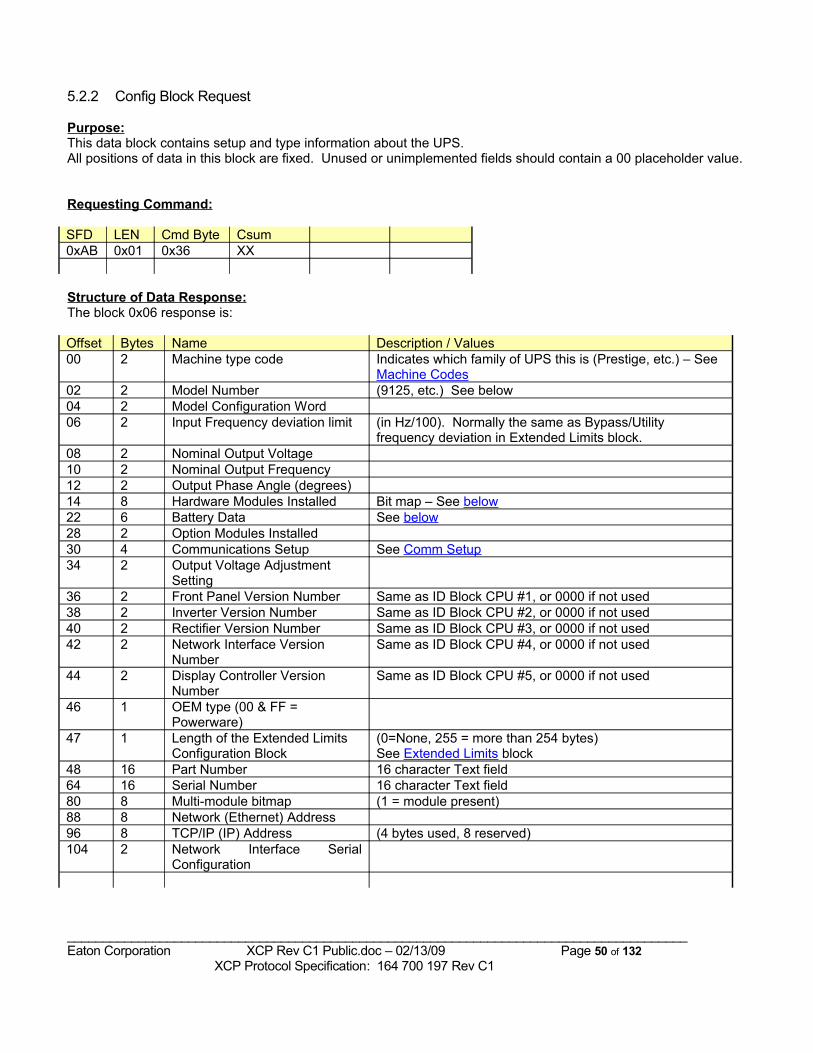
5.2.2 Config Block Request
Purpose:This data block contains setup and type information about the UPS. All positions of data in this block are fixed. Unused or unimplemented fields should contain a 00 placeholder value.
Requesting Command:
SFD LEN Cmd Byte Csum0xAB 0x01 0x36 XX
Structure of Data Response:The block 0x06 response is:
Offset Bytes Name Description / Values00 2 Machine type code Indicates which family of UPS this is (Prestige, etc.) – See
Machine Codes02 2 Model Number (9125, etc.) See below04 2 Model Configuration Word06 2 Input Frequency deviation limit (in Hz/100). Normally the same as Bypass/Utility
frequency deviation in Extended Limits block.08 2 Nominal Output Voltage10 2 Nominal Output Frequency12 2 Output Phase Angle (degrees)14 8 Hardware Modules Installed Bit map – See below22 6 Battery Data See below28 2 Option Modules Installed30 4 Communications Setup See Comm Setup34 2 Output Voltage Adjustment
Setting36 2 Front Panel Version Number Same as ID Block CPU #1, or 0000 if not used38 2 Inverter Version Number Same as ID Block CPU #2, or 0000 if not used40 2 Rectifier Version Number Same as ID Block CPU #3, or 0000 if not used42 2 Network Interface Version
NumberSame as ID Block CPU #4, or 0000 if not used
44 2 Display Controller Version Number
Same as ID Block CPU #5, or 0000 if not used
46 1 OEM type (00 & FF = Powerware)
47 1 Length of the Extended Limits Configuration Block
(0=None, 255 = more than 254 bytes)See Extended Limits block
48 16 Part Number 16 character Text field64 16 Serial Number 16 character Text field80 8 Multi-module bitmap (1 = module present)88 8 Network (Ethernet) Address96 8 TCP/IP (IP) Address (4 bytes used, 8 reserved)104 2 Network Interface Serial
Configuration
_______________________________________________________________________________________Eaton Corporation XCP Rev C1 Public.doc – 02/13/09 Page 50 of 132 XCP Protocol Specification: 164 700 197 Rev C1
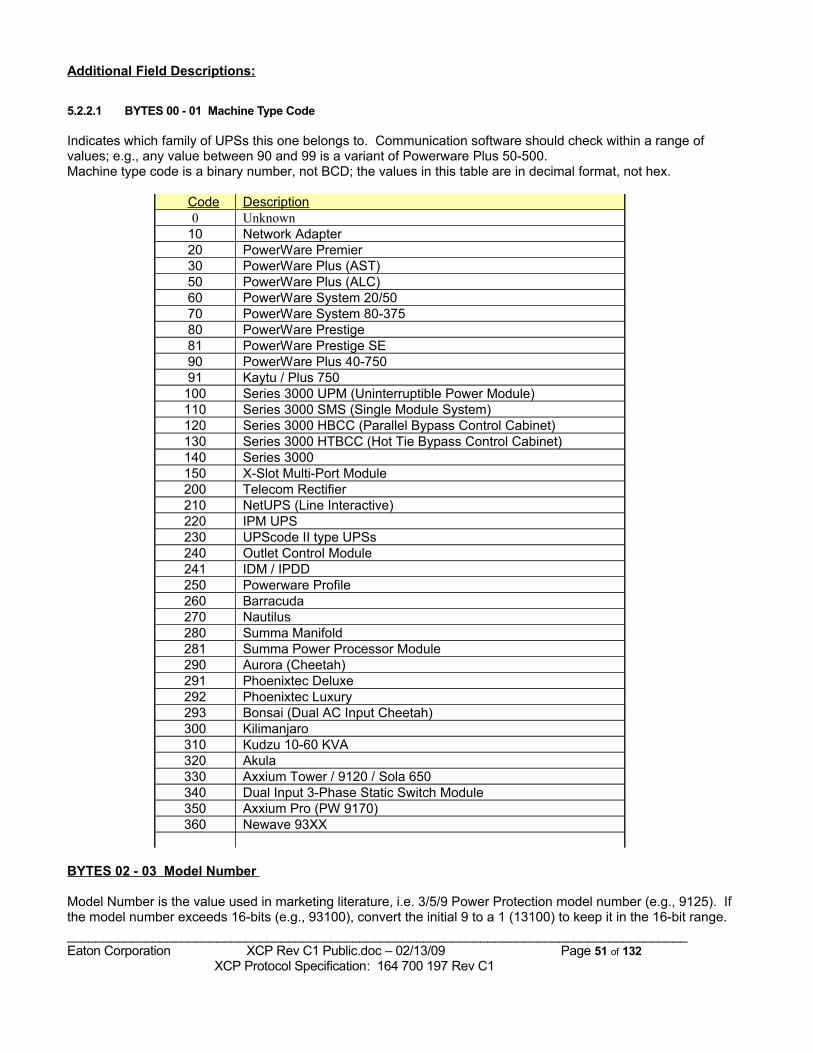
Additional Field Descriptions:
5.2.2.1 BYTES 00 - 01 Machine Type Code
Indicates which family of UPSs this one belongs to. Communication software should check within a range of values; e.g., any value between 90 and 99 is a variant of Powerware Plus 50-500.Machine type code is a binary number, not BCD; the values in this table are in decimal format, not hex.
Code Description0 Unknown
10 Network Adapter20 PowerWare Premier30 PowerWare Plus (AST)50 PowerWare Plus (ALC)60 PowerWare System 20/5070 PowerWare System 80-37580 PowerWare Prestige81 PowerWare Prestige SE90 PowerWare Plus 40-75091 Kaytu / Plus 750
100 Series 3000 UPM (Uninterruptible Power Module)110 Series 3000 SMS (Single Module System)120 Series 3000 HBCC (Parallel Bypass Control Cabinet)130 Series 3000 HTBCC (Hot Tie Bypass Control Cabinet)140 Series 3000 150 X-Slot Multi-Port Module200 Telecom Rectifier210 NetUPS (Line Interactive)220 IPM UPS230 UPScode II type UPSs240 Outlet Control Module241 IDM / IPDD250 Powerware Profile260 Barracuda270 Nautilus280 Summa Manifold281 Summa Power Processor Module290 Aurora (Cheetah)291 Phoenixtec Deluxe292 Phoenixtec Luxury293 Bonsai (Dual AC Input Cheetah)300 Kilimanjaro310 Kudzu 10-60 KVA320 Akula330 Axxium Tower / 9120 / Sola 650340 Dual Input 3-Phase Static Switch Module350 Axxium Pro (PW 9170)360 Newave 93XX
BYTES 02 - 03 Model Number
Model Number is the value used in marketing literature, i.e. 3/5/9 Power Protection model number (e.g., 9125). If the model number exceeds 16-bits (e.g., 93100), convert the initial 9 to a 1 (13100) to keep it in the 16-bit range._______________________________________________________________________________________Eaton Corporation XCP Rev C1 Public.doc – 02/13/09 Page 51 of 132 XCP Protocol Specification: 164 700 197 Rev C1
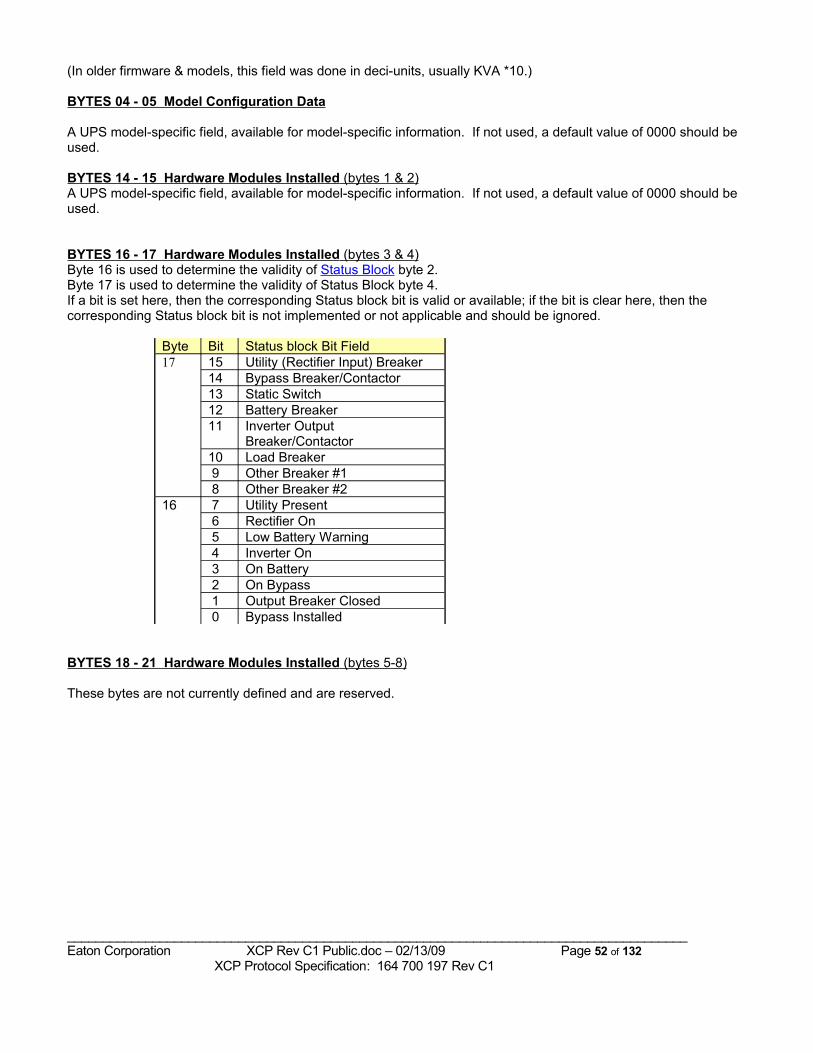
(In older firmware & models, this field was done in deci-units, usually KVA *10.)
BYTES 04 - 05 Model Configuration Data
A UPS model-specific field, available for model-specific information. If not used, a default value of 0000 should be used.
BYTES 14 - 15 Hardware Modules Installed (bytes 1 & 2) A UPS model-specific field, available for model-specific information. If not used, a default value of 0000 should be used.
BYTES 16 - 17 Hardware Modules Installed (bytes 3 & 4) Byte 16 is used to determine the validity of Status Block byte 2. Byte 17 is used to determine the validity of Status Block byte 4.If a bit is set here, then the corresponding Status block bit is valid or available; if the bit is clear here, then the corresponding Status block bit is not implemented or not applicable and should be ignored.
Byte Bit Status block Bit Field17 15 Utility (Rectifier Input) Breaker
14 Bypass Breaker/Contactor13 Static Switch12 Battery Breaker11 Inverter Output
Breaker/Contactor10 Load Breaker 9 Other Breaker #1 8 Other Breaker #2
16 7 Utility Present 6 Rectifier On 5 Low Battery Warning 4 Inverter On 3 On Battery 2 On Bypass 1 Output Breaker Closed 0 Bypass Installed
BYTES 18 - 21 Hardware Modules Installed (bytes 5-8)
These bytes are not currently defined and are reserved.
_______________________________________________________________________________________Eaton Corporation XCP Rev C1 Public.doc – 02/13/09 Page 52 of 132 XCP Protocol Specification: 164 700 197 Rev C1
5.2.2.2 BYTES 22 - 27 Battery Data
Bytes 22 and 23:Undefined at this time.
Bytes 24 and 25: BATTERY DCUV VALUE
Per cell voltage value used to cause the inverter to shutdown due to DCUV at full rated load.
Values are: (volts/cell) * 100 (i.e. value of 167 means 1.67 volts per cell, value of 175 means 1.75 volts per cell)
Byte 26: NUMBER OF BATTERY STRINGS
.The number of Internal and External Battery Strings attached to this UPS.This value may be settable with Set Config Param #15, Battery Data1 Set.
Byte 27: Undefined at this time.
BYTES 28-29 Option Modules Installed
There are currently no defined Option Modules.
_______________________________________________________________________________________Eaton Corporation XCP Rev C1 Public.doc – 02/13/09 Page 53 of 132 XCP Protocol Specification: 164 700 197 Rev C1
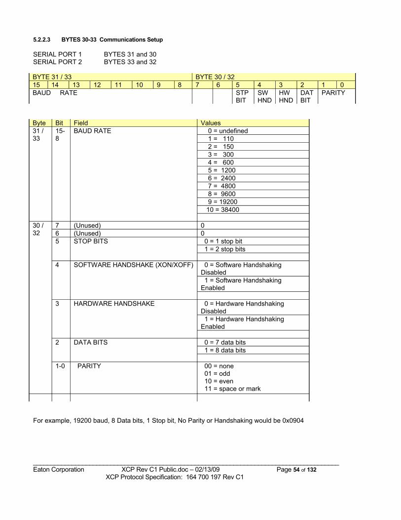
5.2.2.3 BYTES 30-33 Communications Setup
SERIAL PORT 1 BYTES 31 and 30SERIAL PORT 2 BYTES 33 and 32
BYTE 31 / 33 BYTE 30 / 3215 14 13 12 11 10 9 8 7 6 5 4 3 2 1 0BAUD RATE STP
BITSW HND
HW HND
DAT BIT
PARITY
Byte Bit Field Values31 / 33
15-8
BAUD RATE 0 = undefined 1 = 110 2 = 150 3 = 300 4 = 600 5 = 1200 6 = 2400 7 = 4800 8 = 9600 9 = 19200 10 = 38400
30 / 32
7 (Unused) 06 (Unused) 05 STOP BITS 0 = 1 stop bit
1 = 2 stop bits
4 SOFTWARE HANDSHAKE (XON/XOFF) 0 = Software Handshaking Disabled 1 = Software Handshaking Enabled
3 HARDWARE HANDSHAKE 0 = Hardware Handshaking Disabled 1 = Hardware Handshaking Enabled
2 DATA BITS 0 = 7 data bits 1 = 8 data bits
1-0 PARITY 00 = none 01 = odd 10 = even 11 = space or mark
For example, 19200 baud, 8 Data bits, 1 Stop bit, No Parity or Handshaking would be 0x0904
_______________________________________________________________________________________Eaton Corporation XCP Rev C1 Public.doc – 02/13/09 Page 54 of 132 XCP Protocol Specification: 164 700 197 Rev C1
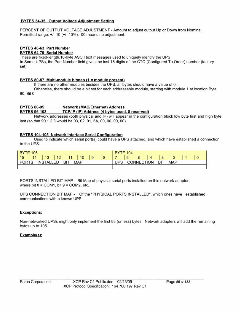
BYTES 34-35 Output Voltage Adjustment Setting
PERCENT OF OUTPUT VOLTAGE ADJUSTMENT - Amount to adjust output Up or Down from Nominal. Permitted range: +/- 10 (+/- 10%). 00 means no adjustment.
BYTES 48-63 Part NumberBYTES 64-79 Serial NumberThese are fixed-length,16-byte ASCII text messages used to uniquely identify the UPS. In Some UPSs, the Part Number field gives the last 16 digits of the CTO (Configured To Order) number (factory set).
BYTES 80-87 Multi-module bitmap (1 = module present)If there are no other modules besides the UPS, all bytes should have a value of 0.Otherwise, there should be a bit set for each addressable module, starting with module 1 at location Byte
80, Bit 0.
BYTES 88-95 Network (MAC/Ethernet) Address BYTES 96-103 TCP/IP (IP) Address (4 bytes used, 8 reserved)
Network addresses (both physical and IP) will appear in the configuration block low byte first and high byte last (so that 90.1.2.3 would be 03, 02, 01, 5A, 00, 00, 00, 00).
BYTES 104-105 Network Interface Serial ConfigurationUsed to indicate which serial port(s) could have a UPS attached, and which have established a connection
to the UPS.
BYTE 105 BYTE 10415 14 13 12 11 10 9 8 7 6 5 4 3 2 1 0PORTS INSTALLED BIT MAP UPS CONNECTION BIT MAP
PORTS INSTALLED BIT MAP - Bit Map of physical serial ports installed on this network adapter,where bit 8 = COM1, bit 9 = COM2, etc.
UPS CONNECTION BIT MAP - Of the "PHYSICAL PORTS INSTALLED", which ones have established communications with a known UPS.
Exceptions:
Non-networked UPSs might only implement the first 88 (or less) bytes. Network adapters will add the remaining bytes up to 105.
Example(s):
_______________________________________________________________________________________Eaton Corporation XCP Rev C1 Public.doc – 02/13/09 Page 55 of 132 XCP Protocol Specification: 164 700 197 Rev C1
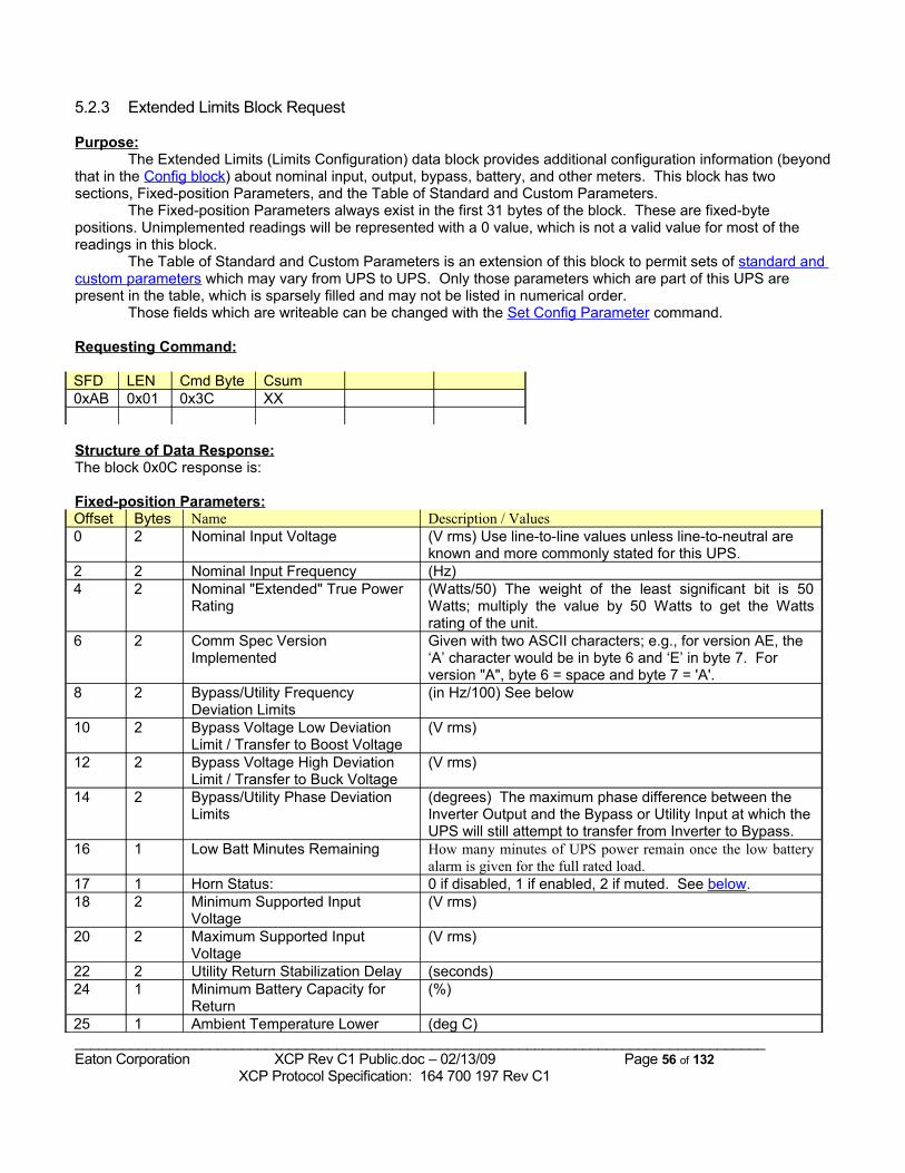
5.2.3 Extended Limits Block Request
Purpose:The Extended Limits (Limits Configuration) data block provides additional configuration information (beyond
that in the Config block) about nominal input, output, bypass, battery, and other meters. This block has two sections, Fixed-position Parameters, and the Table of Standard and Custom Parameters.
The Fixed-position Parameters always exist in the first 31 bytes of the block. These are fixed-byte positions. Unimplemented readings will be represented with a 0 value, which is not a valid value for most of the readings in this block.
The Table of Standard and Custom Parameters is an extension of this block to permit sets of standard and custom parameters which may vary from UPS to UPS. Only those parameters which are part of this UPS are present in the table, which is sparsely filled and may not be listed in numerical order.
Those fields which are writeable can be changed with the Set Config Parameter command.
Requesting Command:
SFD LEN Cmd Byte Csum0xAB 0x01 0x3C XX
Structure of Data Response:The block 0x0C response is:
Fixed-position Parameters:Offset Bytes Name Description / Values0 2 Nominal Input Voltage (V rms) Use line-to-line values unless line-to-neutral are
known and more commonly stated for this UPS.2 2 Nominal Input Frequency (Hz)4 2 Nominal "Extended" True Power
Rating (Watts/50) The weight of the least significant bit is 50 Watts; multiply the value by 50 Watts to get the Watts rating of the unit.
6 2 Comm Spec Version Implemented
Given with two ASCII characters; e.g., for version AE, the ‘A’ character would be in byte 6 and ‘E’ in byte 7. For version "A", byte 6 = space and byte 7 = 'A'.
8 2 Bypass/Utility Frequency Deviation Limits
(in Hz/100) See below
10 2 Bypass Voltage Low Deviation Limit / Transfer to Boost Voltage
(V rms)
12 2 Bypass Voltage High Deviation Limit / Transfer to Buck Voltage
(V rms)
14 2 Bypass/Utility Phase Deviation Limits
(degrees) The maximum phase difference between the Inverter Output and the Bypass or Utility Input at which the UPS will still attempt to transfer from Inverter to Bypass.
16 1 Low Batt Minutes Remaining How many minutes of UPS power remain once the low battery alarm is given for the full rated load.
17 1 Horn Status: 0 if disabled, 1 if enabled, 2 if muted. See below.18 2 Minimum Supported Input
Voltage (V rms)
20 2 Maximum Supported Input Voltage
(V rms)
22 2 Utility Return Stabilization Delay (seconds)24 1 Minimum Battery Capacity for
Return (%)
25 1 Ambient Temperature Lower (deg C)_______________________________________________________________________________________Eaton Corporation XCP Rev C1 Public.doc – 02/13/09 Page 56 of 132 XCP Protocol Specification: 164 700 197 Rev C1
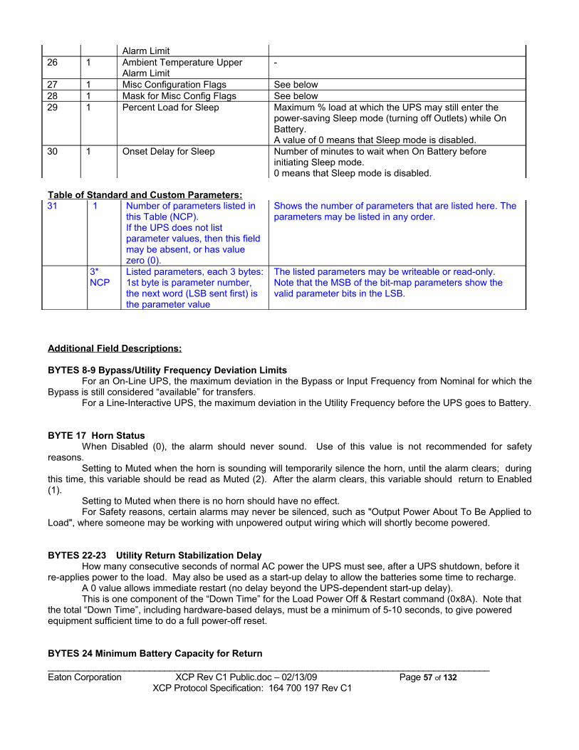
Alarm Limit 26 1 Ambient Temperature Upper
Alarm Limit-
27 1 Misc Configuration Flags See below28 1 Mask for Misc Config Flags See below29 1 Percent Load for Sleep Maximum % load at which the UPS may still enter the
power-saving Sleep mode (turning off Outlets) while On Battery. A value of 0 means that Sleep mode is disabled.
30 1 Onset Delay for Sleep Number of minutes to wait when On Battery before initiating Sleep mode. 0 means that Sleep mode is disabled.
Table of Standard and Custom Parameters:31 1 Number of parameters listed in
this Table (NCP).If the UPS does not list parameter values, then this field may be absent, or has value zero (0).
Shows the number of parameters that are listed here. The parameters may be listed in any order.
3* NCP
Listed parameters, each 3 bytes: 1st byte is parameter number, the next word (LSB sent first) is the parameter value
The listed parameters may be writeable or read-only.Note that the MSB of the bit-map parameters show the valid parameter bits in the LSB.
Additional Field Descriptions:
BYTES 8-9 Bypass/Utility Frequency Deviation LimitsFor an On-Line UPS, the maximum deviation in the Bypass or Input Frequency from Nominal for which the
Bypass is still considered “available” for transfers.For a Line-Interactive UPS, the maximum deviation in the Utility Frequency before the UPS goes to Battery.
BYTE 17 Horn StatusWhen Disabled (0), the alarm should never sound. Use of this value is not recommended for safety
reasons.Setting to Muted when the horn is sounding will temporarily silence the horn, until the alarm clears; during
this time, this variable should be read as Muted (2). After the alarm clears, this variable should return to Enabled (1).
Setting to Muted when there is no horn should have no effect.For Safety reasons, certain alarms may never be silenced, such as "Output Power About To Be Applied to
Load", where someone may be working with unpowered output wiring which will shortly become powered.
BYTES 22-23 Utility Return Stabilization DelayHow many consecutive seconds of normal AC power the UPS must see, after a UPS shutdown, before it
re-applies power to the load. May also be used as a start-up delay to allow the batteries some time to recharge.A 0 value allows immediate restart (no delay beyond the UPS-dependent start-up delay).This is one component of the “Down Time” for the Load Power Off & Restart command (0x8A). Note that
the total “Down Time”, including hardware-based delays, must be a minimum of 5-10 seconds, to give powered equipment sufficient time to do a full power-off reset.
BYTES 24 Minimum Battery Capacity for Return _______________________________________________________________________________________Eaton Corporation XCP Rev C1 Public.doc – 02/13/09 Page 57 of 132 XCP Protocol Specification: 164 700 197 Rev C1
The minimum percent charge that the Batteries must have, after a UPS shutdown, before the UPS re-applies power to the load.
A 0 value allows immediate restart (no delay).If both the Utility Return Stabilization Delay and the Minimum Battery Capacity for Return are non-zero
values, then the UPS will not restore load power until both are satisfied.
_______________________________________________________________________________________Eaton Corporation XCP Rev C1 Public.doc – 02/13/09 Page 58 of 132 XCP Protocol Specification: 164 700 197 Rev C1
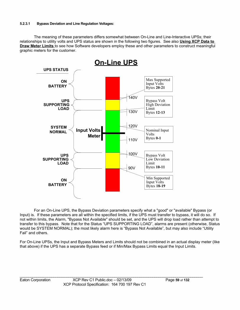
5.2.3.1 Bypass Deviation and Line Regulation Voltages:
The meaning of these parameters differs somewhat between On-Line and Line-Interactive UPSs; their relationships to utility volts and UPS status are shown in the following two figures. See also Using XCP Data to Draw Meter Limits to see how Software developers employ these and other parameters to construct meaningful graphic meters for the customer.
Min SupportedInput VoltsBytes 18-19
Nominal InputVoltsBytes 0-1
Max SupportedInput VoltsBytes 20-21
Bypass VoltHigh DeviationLimitBytes 12-13
Bypass VoltLow DeviationLimitBytes 10-11
Input VoltsMeter
120V
130V
110V
100V
140V
90V
On-Line UPS
SYSTEMNORMAL
UPSSUPPORTING
LOAD
UPSSUPPORTING
LOAD
ONBATTERY
ONBATTERY
UPS STATUS
For an On-Line UPS, the Bypass Deviation parameters specify what a "good" or "available" Bypass (or Input) is. If these parameters are all within the specified limits, if the UPS must transfer to bypass, it will do so. If not within limits, the Alarm, "Bypass Not Available" should be set, and the UPS will drop load rather than attempt to transfer to this bypass. Note that for the Status “UPS SUPPORTING LOAD”, alarms are present (otherwise, Status would be SYSTEM NORMAL); the most likely alarm here is “Bypass Not Available”, but may also include “Utility Fail” and others.
For On-Line UPSs, the Input and Bypass Meters and Limits should not be combined in an actual display meter (like that above) if the UPS has a separate Bypass feed or if Min/Max Bypass Limits equal the Input Limits.
_______________________________________________________________________________________Eaton Corporation XCP Rev C1 Public.doc – 02/13/09 Page 59 of 132 XCP Protocol Specification: 164 700 197 Rev C1
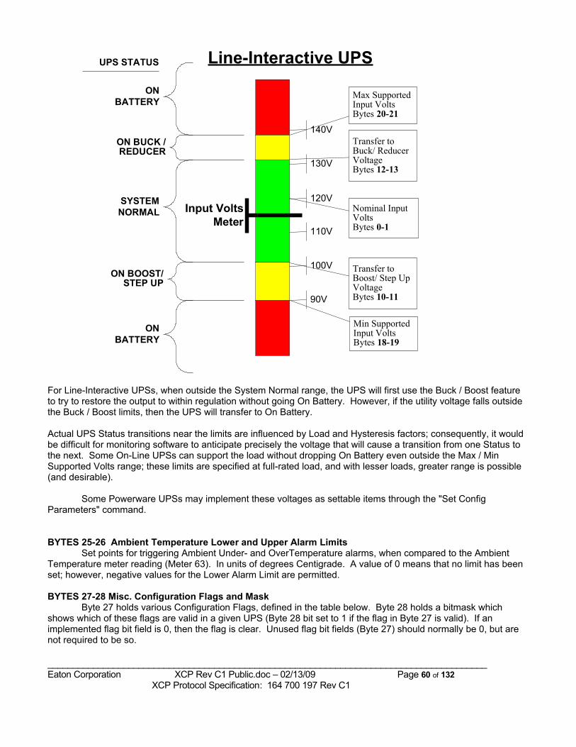
Min SupportedInput VoltsBytes 18-19
Nominal InputVoltsBytes 0-1
Max SupportedInput VoltsBytes 20-21
Transfer toBuck/ ReducerVoltageBytes 12-13
Transfer toBoost/ Step UpVoltageBytes 10-11
Input VoltsMeter
120V
130V
110V
100V
140V
90V
Line-Interactive UPS
SYSTEMNORMAL
ON BUCK /REDUCER
ON BOOST/STEP UP
ONBATTERY
ONBATTERY
UPS STATUS
For Line-Interactive UPSs, when outside the System Normal range, the UPS will first use the Buck / Boost feature to try to restore the output to within regulation without going On Battery. However, if the utility voltage falls outside the Buck / Boost limits, then the UPS will transfer to On Battery.
Actual UPS Status transitions near the limits are influenced by Load and Hysteresis factors; consequently, it would be difficult for monitoring software to anticipate precisely the voltage that will cause a transition from one Status to the next. Some On-Line UPSs can support the load without dropping On Battery even outside the Max / Min Supported Volts range; these limits are specified at full-rated load, and with lesser loads, greater range is possible (and desirable).
Some Powerware UPSs may implement these voltages as settable items through the "Set Config Parameters" command.
BYTES 25-26 Ambient Temperature Lower and Upper Alarm LimitsSet points for triggering Ambient Under- and OverTemperature alarms, when compared to the Ambient
Temperature meter reading (Meter 63). In units of degrees Centigrade. A value of 0 means that no limit has been set; however, negative values for the Lower Alarm Limit are permitted.
BYTES 27-28 Misc. Configuration Flags and MaskByte 27 holds various Configuration Flags, defined in the table below. Byte 28 holds a bitmask which
shows which of these flags are valid in a given UPS (Byte 28 bit set to 1 if the flag in Byte 27 is valid). If an implemented flag bit field is 0, then the flag is clear. Unused flag bit fields (Byte 27) should normally be 0, but are not required to be so.
_______________________________________________________________________________________Eaton Corporation XCP Rev C1 Public.doc – 02/13/09 Page 60 of 132 XCP Protocol Specification: 164 700 197 Rev C1
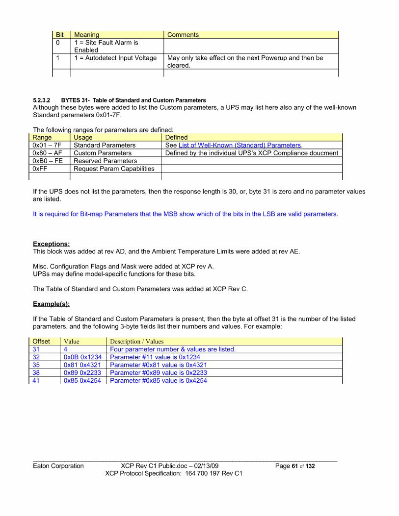
Bit Meaning Comments0 1 = Site Fault Alarm is
Enabled1 1 = Autodetect Input Voltage May only take effect on the next Powerup and then be
cleared.
5.2.3.2 BYTES 31- Table of Standard and Custom ParametersAlthough these bytes were added to list the Custom parameters, a UPS may list here also any of the well-known Standard parameters 0x01-7F.
The following ranges for parameters are defined:Range Usage Defined0x01 – 7F Standard Parameters See List of Well-Known (Standard) Parameters.0x80 – AF Custom Parameters Defined by the individual UPS’s XCP Compliance doucment0xB0 – FE Reserved Parameters0xFF Request Param Capabilities
If the UPS does not list the parameters, then the response length is 30, or, byte 31 is zero and no parameter values are listed.
It is required for Bit-map Parameters that the MSB show which of the bits in the LSB are valid parameters.
Exceptions:This block was added at rev AD, and the Ambient Temperature Limits were added at rev AE.
Misc. Configuration Flags and Mask were added at XCP rev A.UPSs may define model-specific functions for these bits.
The Table of Standard and Custom Parameters was added at XCP Rev C.
Example(s):
If the Table of Standard and Custom Parameters is present, then the byte at offset 31 is the number of the listed parameters, and the following 3-byte fields list their numbers and values. For example:
Offset Value Description / Values31 4 Four parameter number & values are listed.32 0x0B 0x1234 Parameter #11 value is 0x123435 0x81 0x4321 Parameter #0x81 value is 0x432138 0x89 0x2233 Parameter #0x89 value is 0x223341 0x85 0x4254 Parameter #0x85 value is 0x4254
_______________________________________________________________________________________Eaton Corporation XCP Rev C1 Public.doc – 02/13/09 Page 61 of 132 XCP Protocol Specification: 164 700 197 Rev C1
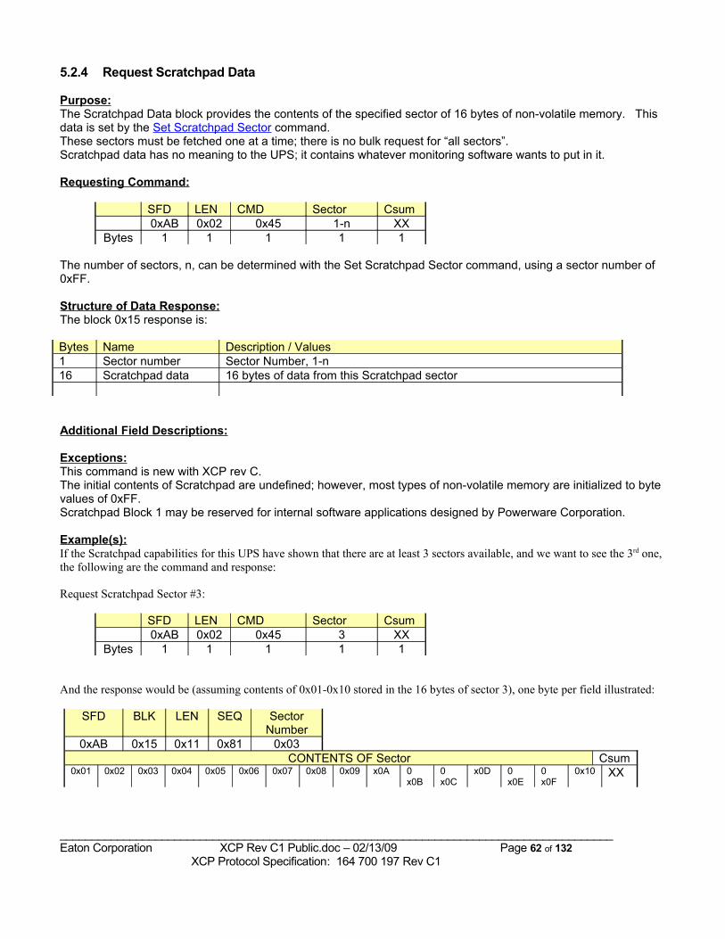
5.2.4 Request Scratchpad Data
Purpose:The Scratchpad Data block provides the contents of the specified sector of 16 bytes of non-volatile memory. This data is set by the Set Scratchpad Sector command.These sectors must be fetched one at a time; there is no bulk request for “all sectors”.Scratchpad data has no meaning to the UPS; it contains whatever monitoring software wants to put in it.
Requesting Command:
SFD LEN CMD Sector Csum0xAB 0x02 0x45 1-n XX
Bytes 1 1 1 1 1
The number of sectors, n, can be determined with the Set Scratchpad Sector command, using a sector number of 0xFF.
Structure of Data Response:The block 0x15 response is:
Bytes Name Description / Values1 Sector number Sector Number, 1-n16 Scratchpad data 16 bytes of data from this Scratchpad sector
Additional Field Descriptions:
Exceptions:This command is new with XCP rev C.The initial contents of Scratchpad are undefined; however, most types of non-volatile memory are initialized to byte values of 0xFF.Scratchpad Block 1 may be reserved for internal software applications designed by Powerware Corporation.
Example(s):If the Scratchpad capabilities for this UPS have shown that there are at least 3 sectors available, and we want to see the 3rd one, the following are the command and response:
Request Scratchpad Sector #3:
SFD LEN CMD Sector Csum0xAB 0x02 0x45 3 XX
Bytes 1 1 1 1 1
And the response would be (assuming contents of 0x01-0x10 stored in the 16 bytes of sector 3), one byte per field illustrated:
SFD BLK LEN SEQ Sector Number
0xAB 0x15 0x11 0x81 0x03CONTENTS OF Sector Csum
0x01 0x02 0x03 0x04 0x05 0x06 0x07 0x08 0x09 x0A 0x0B
0x0C
x0D 0x0E
0x0F
0x10 XX
_______________________________________________________________________________________Eaton Corporation XCP Rev C1 Public.doc – 02/13/09 Page 62 of 132 XCP Protocol Specification: 164 700 197 Rev C1
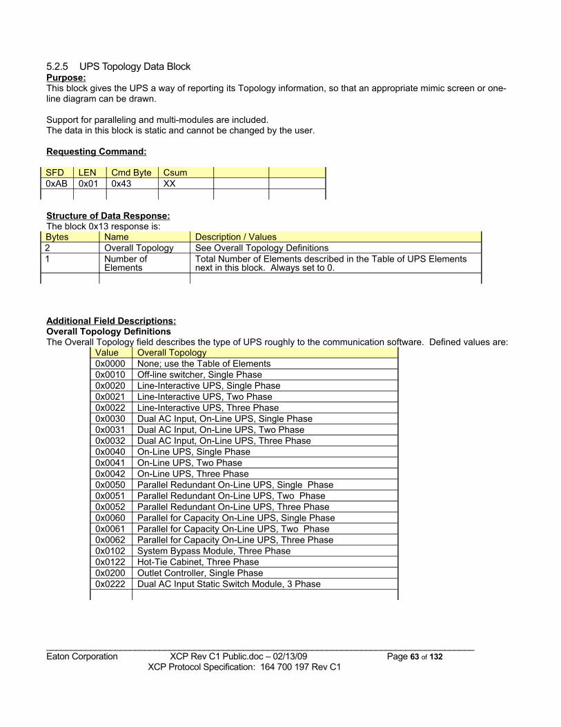
5.2.5 UPS Topology Data BlockPurpose:This block gives the UPS a way of reporting its Topology information, so that an appropriate mimic screen or one-line diagram can be drawn.
Support for paralleling and multi-modules are included.The data in this block is static and cannot be changed by the user.
Requesting Command:
SFD LEN Cmd Byte Csum0xAB 0x01 0x43 XX
Structure of Data Response:The block 0x13 response is:Bytes Name Description / Values2 Overall Topology See Overall Topology Definitions1 Number of
ElementsTotal Number of Elements described in the Table of UPS Elements next in this block. Always set to 0.
Additional Field Descriptions:Overall Topology DefinitionsThe Overall Topology field describes the type of UPS roughly to the communication software. Defined values are:
Value Overall Topology0x0000 None; use the Table of Elements0x0010 Off-line switcher, Single Phase0x0020 Line-Interactive UPS, Single Phase0x0021 Line-Interactive UPS, Two Phase0x0022 Line-Interactive UPS, Three Phase0x0030 Dual AC Input, On-Line UPS, Single Phase0x0031 Dual AC Input, On-Line UPS, Two Phase0x0032 Dual AC Input, On-Line UPS, Three Phase0x0040 On-Line UPS, Single Phase0x0041 On-Line UPS, Two Phase0x0042 On-Line UPS, Three Phase0x0050 Parallel Redundant On-Line UPS, Single Phase0x0051 Parallel Redundant On-Line UPS, Two Phase0x0052 Parallel Redundant On-Line UPS, Three Phase0x0060 Parallel for Capacity On-Line UPS, Single Phase0x0061 Parallel for Capacity On-Line UPS, Two Phase0x0062 Parallel for Capacity On-Line UPS, Three Phase0x0102 System Bypass Module, Three Phase0x0122 Hot-Tie Cabinet, Three Phase0x0200 Outlet Controller, Single Phase0x0222 Dual AC Input Static Switch Module, 3 Phase
_______________________________________________________________________________________Eaton Corporation XCP Rev C1 Public.doc – 02/13/09 Page 63 of 132 XCP Protocol Specification: 164 700 197 Rev C1

Exceptions:The Table of UPS Elements is undefined; therefore, this byte should indicate that the Number of Elements is 0.
Example(s):
_______________________________________________________________________________________Eaton Corporation XCP Rev C1 Public.doc – 02/13/09 Page 64 of 132 XCP Protocol Specification: 164 700 197 Rev C1
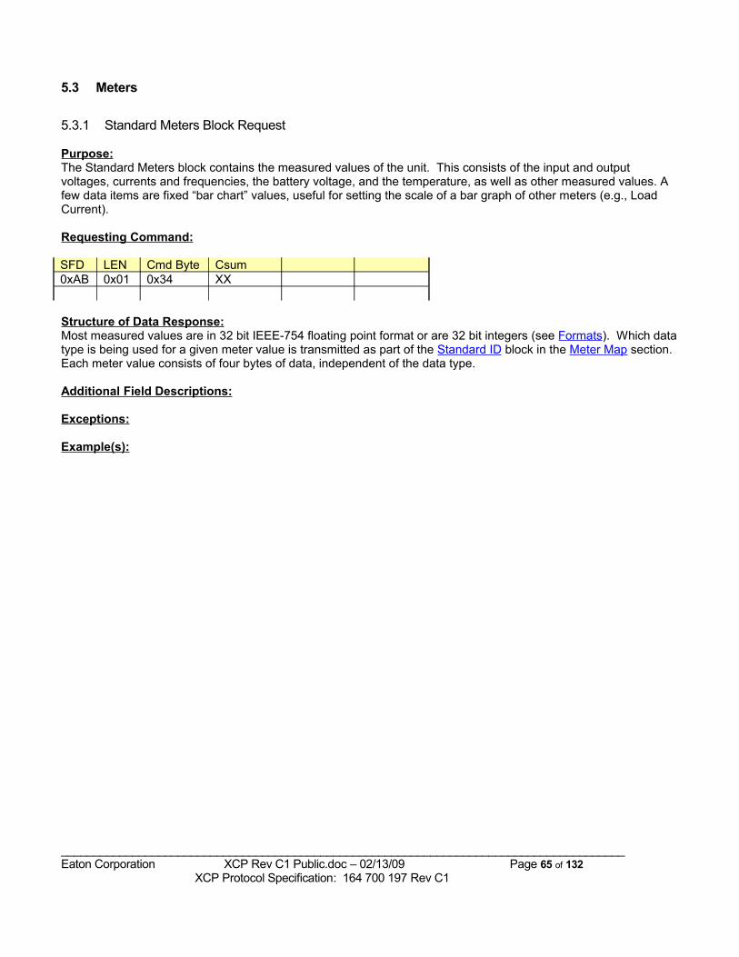
5.3 Meters
5.3.1 Standard Meters Block Request
Purpose:The Standard Meters block contains the measured values of the unit. This consists of the input and output voltages, currents and frequencies, the battery voltage, and the temperature, as well as other measured values. A few data items are fixed “bar chart” values, useful for setting the scale of a bar graph of other meters (e.g., Load Current).
Requesting Command:
SFD LEN Cmd Byte Csum0xAB 0x01 0x34 XX
Structure of Data Response:Most measured values are in 32 bit IEEE-754 floating point format or are 32 bit integers (see Formats). Which data type is being used for a given meter value is transmitted as part of the Standard ID block in the Meter Map section. Each meter value consists of four bytes of data, independent of the data type.
Additional Field Descriptions:
Exceptions:
Example(s):
_______________________________________________________________________________________Eaton Corporation XCP Rev C1 Public.doc – 02/13/09 Page 65 of 132 XCP Protocol Specification: 164 700 197 Rev C1
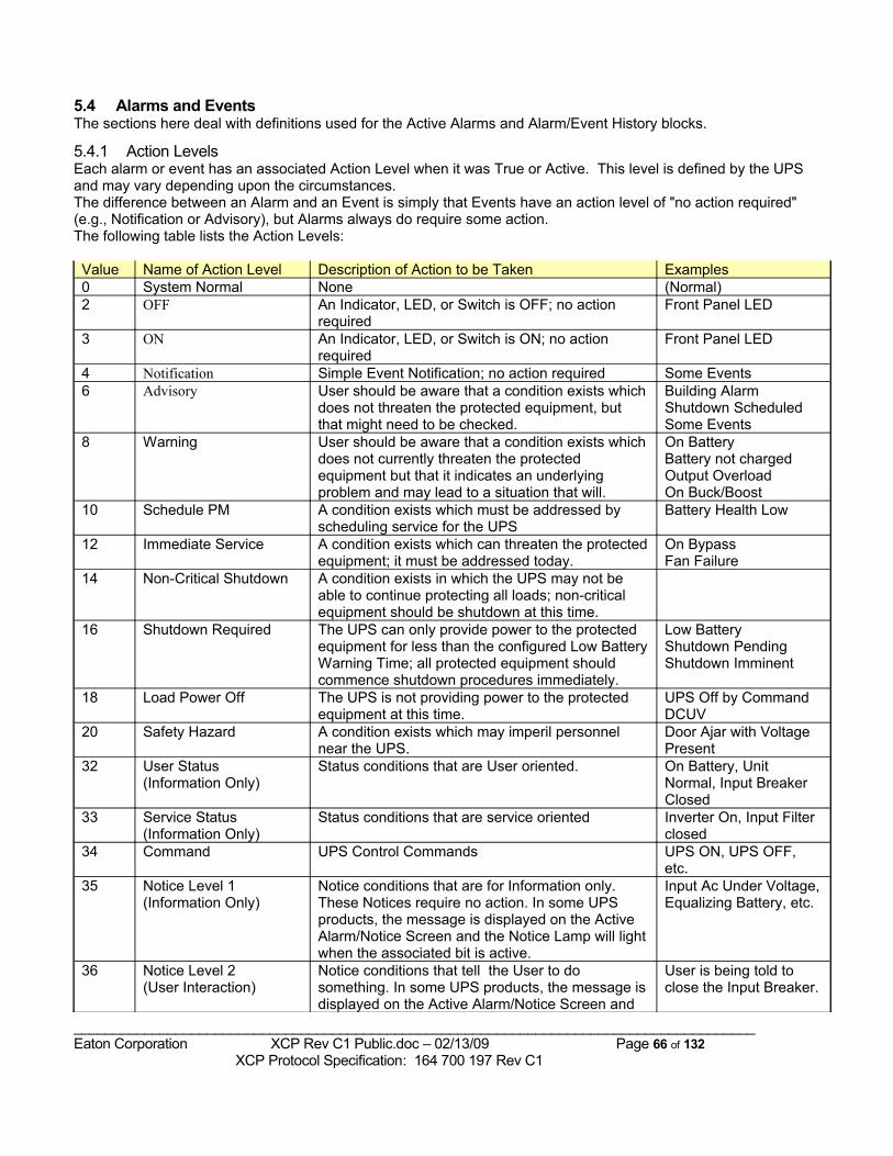
5.4 Alarms and EventsThe sections here deal with definitions used for the Active Alarms and Alarm/Event History blocks.
5.4.1 Action LevelsEach alarm or event has an associated Action Level when it was True or Active. This level is defined by the UPS and may vary depending upon the circumstances.The difference between an Alarm and an Event is simply that Events have an action level of "no action required" (e.g., Notification or Advisory), but Alarms always do require some action.The following table lists the Action Levels:
Value Name of Action Level Description of Action to be Taken Examples0 System Normal None (Normal)2 OFF An Indicator, LED, or Switch is OFF; no action
requiredFront Panel LED
3 ON An Indicator, LED, or Switch is ON; no action required
Front Panel LED
4 Notification Simple Event Notification; no action required Some Events6 Advisory User should be aware that a condition exists which
does not threaten the protected equipment, but that might need to be checked.
Building Alarm Shutdown Scheduled Some Events
8 Warning User should be aware that a condition exists which does not currently threaten the protected equipment but that it indicates an underlying problem and may lead to a situation that will.
On Battery Battery not charged Output Overload On Buck/Boost
10 Schedule PM A condition exists which must be addressed by scheduling service for the UPS
Battery Health Low
12 Immediate Service A condition exists which can threaten the protected equipment; it must be addressed today.
On Bypass Fan Failure
14 Non-Critical Shutdown A condition exists in which the UPS may not be able to continue protecting all loads; non-critical equipment should be shutdown at this time.
16 Shutdown Required The UPS can only provide power to the protected equipment for less than the configured Low Battery Warning Time; all protected equipment should commence shutdown procedures immediately.
Low Battery Shutdown Pending Shutdown Imminent
18 Load Power Off The UPS is not providing power to the protected equipment at this time.
UPS Off by Command DCUV
20 Safety Hazard A condition exists which may imperil personnel near the UPS.
Door Ajar with Voltage Present
32 User Status(Information Only)
Status conditions that are User oriented. On Battery, Unit Normal, Input Breaker Closed
33 Service Status(Information Only)
Status conditions that are service oriented Inverter On, Input Filter closed
34 Command UPS Control Commands UPS ON, UPS OFF, etc.
35 Notice Level 1(Information Only)
Notice conditions that are for Information only. These Notices require no action. In some UPS products, the message is displayed on the Active Alarm/Notice Screen and the Notice Lamp will light when the associated bit is active.
Input Ac Under Voltage, Equalizing Battery, etc.
36 Notice Level 2(User Interaction)
Notice conditions that tell the User to do something. In some UPS products, the message is displayed on the Active Alarm/Notice Screen and
User is being told to close the Input Breaker.
_______________________________________________________________________________________Eaton Corporation XCP Rev C1 Public.doc – 02/13/09 Page 66 of 132 XCP Protocol Specification: 164 700 197 Rev C1
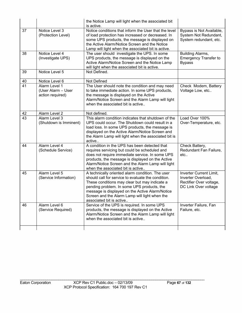
the Notice Lamp will light when the associated bit is active.
37 Notice Level 3(Protection Level)
Notice conditions that inform the User that the level of load protection has increased or decreased. In some UPS products, the message is displayed on the Active Alarm/Notice Screen and the Notice Lamp will light when the associated bit is active.
Bypass is Not Available, System Not Redundant, System redundant, etc.
38 Notice Level 4(Investigate UPS)
The user should investigate the UPS. In some UPS products, the message is displayed on the Active Alarm/Notice Screen and the Notice Lamp will light when the associated bit is active.
Building Alarms, Emergency Transfer to Bypass
39 Notice Level 5 Not Defined.
40 Notice Level 6 Not Defined41 Alarm Level 1
(User Alarm – User action required)
The User should note the condition and may need to take immediate action. In some UPS products, the message is displayed on the Active Alarm/Notice Screen and the Alarm Lamp will light when the associated bit is active..
Check Modem, Battery Voltage Low, etc..
42 Alarm Level 2 Not defined.43 Alarm Level 3
(Shutdown is Imminent)This alarm condition indicates that shutdown of the UPS could occur. The Shutdown could result in a load loss. In some UPS products, the message is displayed on the Active Alarm/Notice Screen and the Alarm Lamp will light when the associated bit is active..
Load Over 100%Over-Temperature, etc.
44 Alarm Level 4(Schedule Service)
A condition in the UPS has been detected that requires servicing but could be scheduled and does not require immediate service. In some UPS products, the message is displayed on the Active Alarm/Notice Screen and the Alarm Lamp will light when the associated bit is active..
Check Battery, Redundant Fan Failure, etc..
45 Alarm Level 5(Service Information)
A technically oriented alarm condition. The user should call for service to evaluate the condition. These conditions may clear but may indicate a pending problem. In some UPS products, the message is displayed on the Active Alarm/Notice Screen and the Alarm Lamp will light when the associated bit is active..
Inverter Current Limit, Inverter Overload, Rectifier Over voltage, DC Link Over voltage
46 Alarm Level 6(Service Required)
Service of the UPS is required. In some UPS products, the message is displayed on the Active Alarm/Notice Screen and the Alarm Lamp will light when the associated bit is active..
Inverter Failure, Fan Failure, etc.
_______________________________________________________________________________________Eaton Corporation XCP Rev C1 Public.doc – 02/13/09 Page 67 of 132 XCP Protocol Specification: 164 700 197 Rev C1
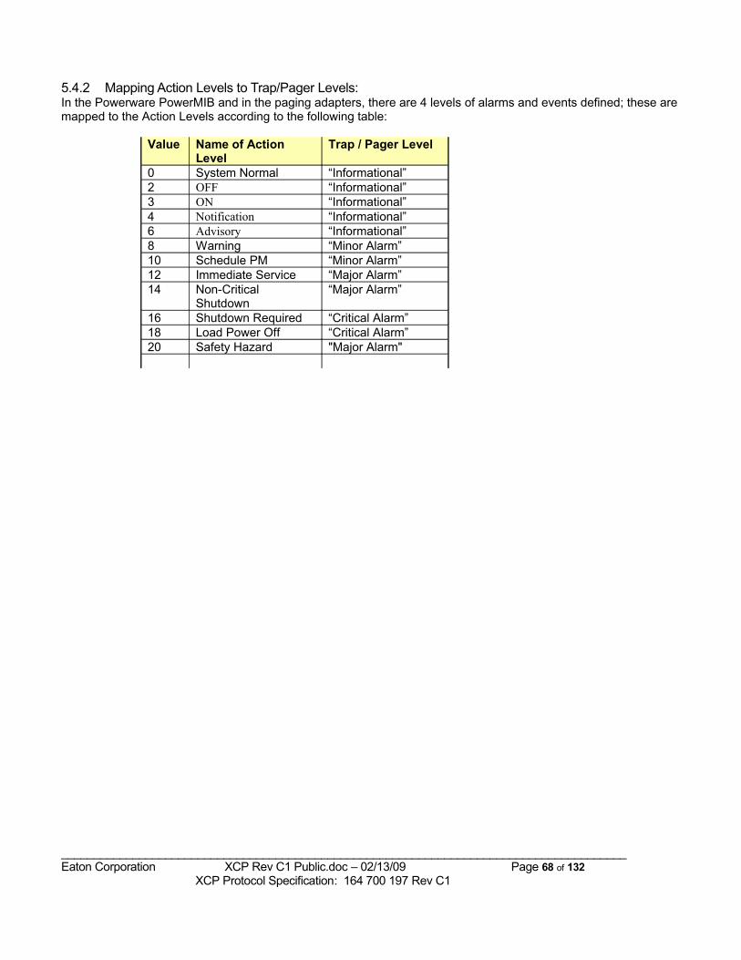
5.4.2 Mapping Action Levels to Trap/Pager Levels:In the Powerware PowerMIB and in the paging adapters, there are 4 levels of alarms and events defined; these are mapped to the Action Levels according to the following table:
Value Name of Action Level
Trap / Pager Level
0 System Normal “Informational”2 OFF “Informational”3 ON “Informational”4 Notification “Informational”6 Advisory “Informational”8 Warning “Minor Alarm”10 Schedule PM “Minor Alarm”12 Immediate Service “Major Alarm”14 Non-Critical
Shutdown“Major Alarm”
16 Shutdown Required “Critical Alarm”18 Load Power Off “Critical Alarm”20 Safety Hazard "Major Alarm"
_______________________________________________________________________________________Eaton Corporation XCP Rev C1 Public.doc – 02/13/09 Page 68 of 132 XCP Protocol Specification: 164 700 197 Rev C1
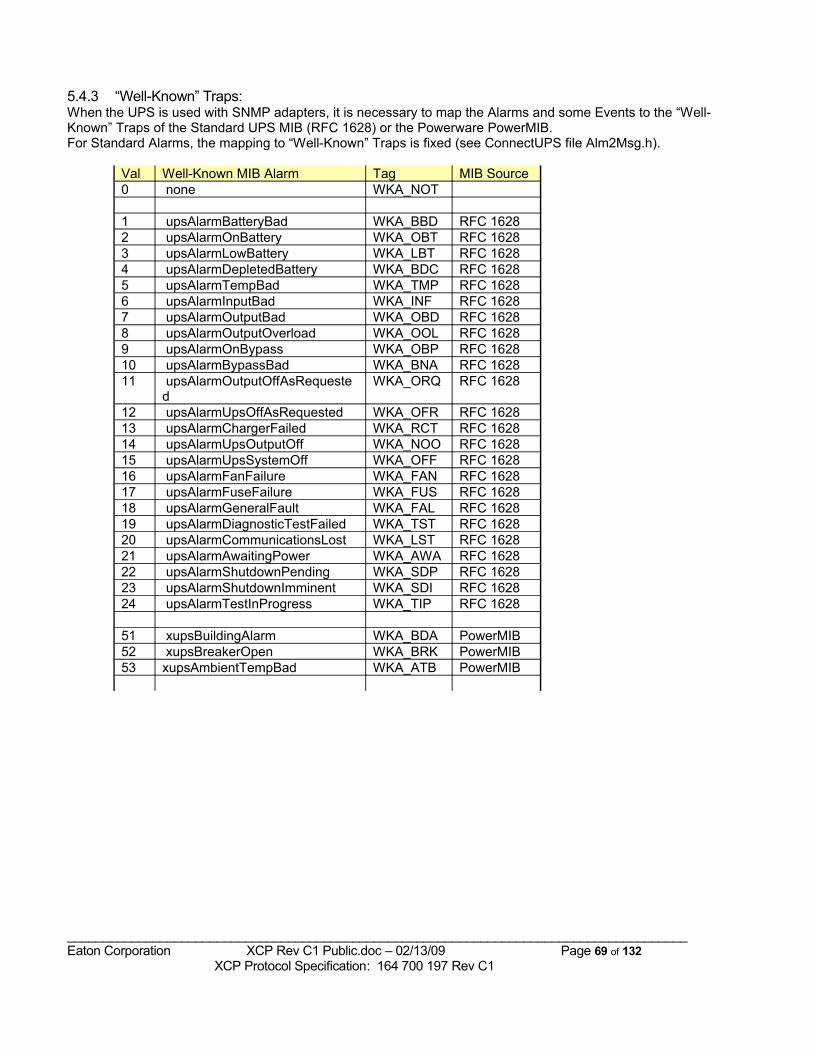
5.4.3 “Well-Known” Traps:When the UPS is used with SNMP adapters, it is necessary to map the Alarms and some Events to the “Well-Known” Traps of the Standard UPS MIB (RFC 1628) or the Powerware PowerMIB. For Standard Alarms, the mapping to “Well-Known” Traps is fixed (see ConnectUPS file Alm2Msg.h).
Val Well-Known MIB Alarm Tag MIB Source0 none WKA_NOT
1 upsAlarmBatteryBad WKA_BBD RFC 16282 upsAlarmOnBattery WKA_OBT RFC 16283 upsAlarmLowBattery WKA_LBT RFC 16284 upsAlarmDepletedBattery WKA_BDC RFC 16285 upsAlarmTempBad WKA_TMP RFC 16286 upsAlarmInputBad WKA_INF RFC 16287 upsAlarmOutputBad WKA_OBD RFC 16288 upsAlarmOutputOverload WKA_OOL RFC 16289 upsAlarmOnBypass WKA_OBP RFC 162810 upsAlarmBypassBad WKA_BNA RFC 162811 upsAlarmOutputOffAsRequeste
d WKA_ORQ RFC 1628
12 upsAlarmUpsOffAsRequested WKA_OFR RFC 162813 upsAlarmChargerFailed WKA_RCT RFC 162814 upsAlarmUpsOutputOff WKA_NOO RFC 162815 upsAlarmUpsSystemOff WKA_OFF RFC 162816 upsAlarmFanFailure WKA_FAN RFC 162817 upsAlarmFuseFailure WKA_FUS RFC 162818 upsAlarmGeneralFault WKA_FAL RFC 162819 upsAlarmDiagnosticTestFailed WKA_TST RFC 162820 upsAlarmCommunicationsLost WKA_LST RFC 162821 upsAlarmAwaitingPower WKA_AWA RFC 162822 upsAlarmShutdownPending WKA_SDP RFC 162823 upsAlarmShutdownImminent WKA_SDI RFC 162824 upsAlarmTestInProgress WKA_TIP RFC 1628
51 xupsBuildingAlarm WKA_BDA PowerMIB52 xupsBreakerOpen WKA_BRK PowerMIB53 xupsAmbientTempBad WKA_ATB PowerMIB
_______________________________________________________________________________________Eaton Corporation XCP Rev C1 Public.doc – 02/13/09 Page 69 of 132 XCP Protocol Specification: 164 700 197 Rev C1
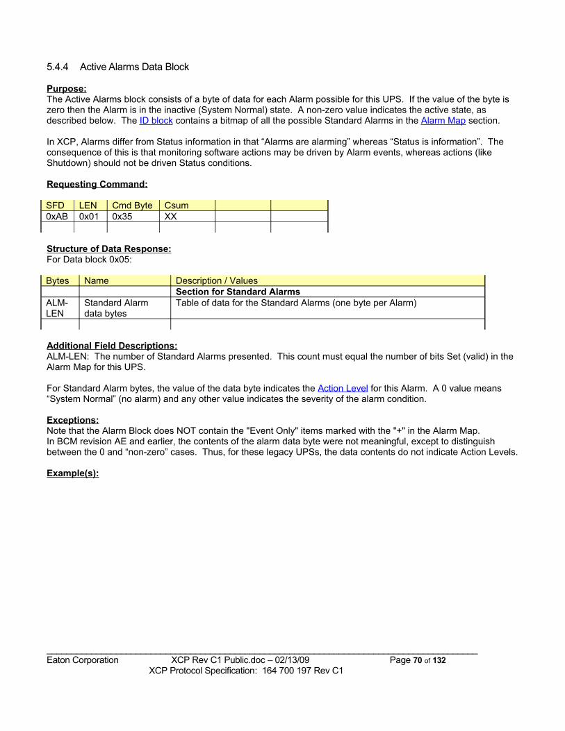
5.4.4 Active Alarms Data Block
Purpose:The Active Alarms block consists of a byte of data for each Alarm possible for this UPS. If the value of the byte is zero then the Alarm is in the inactive (System Normal) state. A non-zero value indicates the active state, as described below. The ID block contains a bitmap of all the possible Standard Alarms in the Alarm Map section.
In XCP, Alarms differ from Status information in that “Alarms are alarming” whereas “Status is information”. The consequence of this is that monitoring software actions may be driven by Alarm events, whereas actions (like Shutdown) should not be driven Status conditions.
Requesting Command:
SFD LEN Cmd Byte Csum0xAB 0x01 0x35 XX
Structure of Data Response:For Data block 0x05:
Bytes Name Description / ValuesSection for Standard Alarms
ALM-LEN
Standard Alarm data bytes
Table of data for the Standard Alarms (one byte per Alarm)
Additional Field Descriptions:ALM-LEN: The number of Standard Alarms presented. This count must equal the number of bits Set (valid) in the Alarm Map for this UPS.
For Standard Alarm bytes, the value of the data byte indicates the Action Level for this Alarm. A 0 value means “System Normal” (no alarm) and any other value indicates the severity of the alarm condition.
Exceptions:Note that the Alarm Block does NOT contain the "Event Only" items marked with the "+" in the Alarm Map.In BCM revision AE and earlier, the contents of the alarm data byte were not meaningful, except to distinguish between the 0 and “non-zero” cases. Thus, for these legacy UPSs, the data contents do not indicate Action Levels.
Example(s):
_______________________________________________________________________________________Eaton Corporation XCP Rev C1 Public.doc – 02/13/09 Page 70 of 132 XCP Protocol Specification: 164 700 197 Rev C1
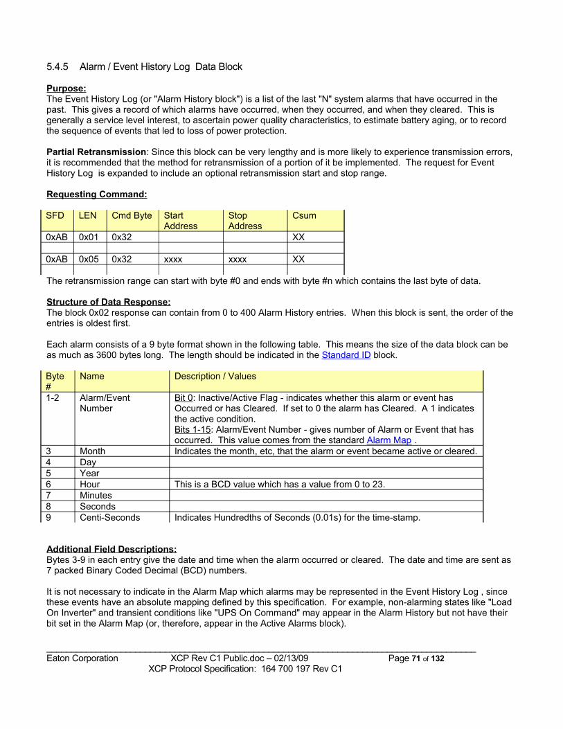
5.4.5 Alarm / Event History Log Data Block
Purpose:The Event History Log (or "Alarm History block") is a list of the last "N" system alarms that have occurred in the past. This gives a record of which alarms have occurred, when they occurred, and when they cleared. This is generally a service level interest, to ascertain power quality characteristics, to estimate battery aging, or to record the sequence of events that led to loss of power protection.
Partial Retransmission: Since this block can be very lengthy and is more likely to experience transmission errors, it is recommended that the method for retransmission of a portion of it be implemented. The request for Event History Log is expanded to include an optional retransmission start and stop range.
Requesting Command:
SFD LEN Cmd Byte Start Address
Stop Address
Csum
0xAB 0x01 0x32 XX
0xAB 0x05 0x32 xxxx xxxx XX
The retransmission range can start with byte #0 and ends with byte #n which contains the last byte of data.
Structure of Data Response:The block 0x02 response can contain from 0 to 400 Alarm History entries. When this block is sent, the order of the entries is oldest first.
Each alarm consists of a 9 byte format shown in the following table. This means the size of the data block can be as much as 3600 bytes long. The length should be indicated in the Standard ID block.
Byte #
Name Description / Values
1-2 Alarm/Event Number
Bit 0: Inactive/Active Flag - indicates whether this alarm or event has Occurred or has Cleared. If set to 0 the alarm has Cleared. A 1 indicates the active condition.Bits 1-15: Alarm/Event Number - gives number of Alarm or Event that has occurred. This value comes from the standard Alarm Map .
3 Month Indicates the month, etc, that the alarm or event became active or cleared.4 Day5 Year6 Hour This is a BCD value which has a value from 0 to 23.7 Minutes8 Seconds9 Centi-Seconds Indicates Hundredths of Seconds (0.01s) for the time-stamp.
Additional Field Descriptions:Bytes 3-9 in each entry give the date and time when the alarm occurred or cleared. The date and time are sent as 7 packed Binary Coded Decimal (BCD) numbers.
It is not necessary to indicate in the Alarm Map which alarms may be represented in the Event History Log , since these events have an absolute mapping defined by this specification. For example, non-alarming states like "Load On Inverter" and transient conditions like "UPS On Command" may appear in the Alarm History but not have their bit set in the Alarm Map (or, therefore, appear in the Active Alarms block).
_______________________________________________________________________________________Eaton Corporation XCP Rev C1 Public.doc – 02/13/09 Page 71 of 132 XCP Protocol Specification: 164 700 197 Rev C1
Exceptions:The UPS cannot update this block while in the process of transmitting it.
To insure that retransmitted data is the same as the original data, the UPS must track whether the Alarm History log has changed since the full history was last transmitted, and NACK any retransmission requests if the Alarm History has changed since the last request.
Example(s):An entry of {0x0183, 0x03, 0x13, 0x98, 0x08, 0x57, 0x38, 0x10} indicates a Fan Failure (Alarm # 193) Occurred at 8:57:38.10 AM on 3/13/1998.
As an example of requesting retransmission, if the alarm block contains 200 entries, using 9 bytes each, there are 1800 binary data bytes to be sent. This will take 1800/121 = 15 data packets. To request just the last 100 bytes (bytes 1700 through 1799) the following command would be sent:{ 0xAB 0x05 0x32 0x06A4 0x0707 csum }
_______________________________________________________________________________________Eaton Corporation XCP Rev C1 Public.doc – 02/13/09 Page 72 of 132 XCP Protocol Specification: 164 700 197 Rev C1
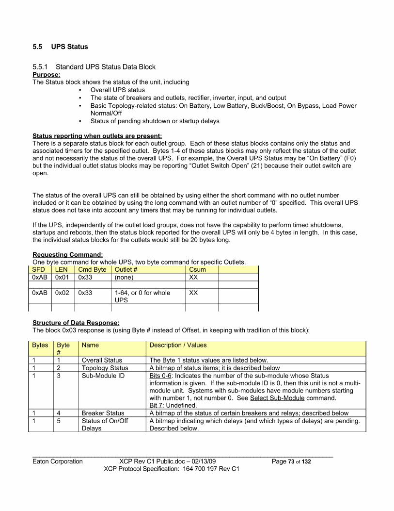
5.5 UPS Status
5.5.1 Standard UPS Status Data BlockPurpose:The Status block shows the status of the unit, including
• Overall UPS status• The state of breakers and outlets, rectifier, inverter, input, and output• Basic Topology-related status: On Battery, Low Battery, Buck/Boost, On Bypass, Load Power
Normal/Off• Status of pending shutdown or startup delays
Status reporting when outlets are present:There is a separate status block for each outlet group. Each of these status blocks contains only the status and associated timers for the specified outlet. Bytes 1-4 of these status blocks may only reflect the status of the outlet and not necessarily the status of the overall UPS. For example, the Overall UPS Status may be “On Battery” (F0) but the individual outlet status blocks may be reporting “Outlet Switch Open” (21) because their outlet switch are open.
The status of the overall UPS can still be obtained by using either the short command with no outlet number included or it can be obtained by using the long command with an outlet number of “0” specified. This overall UPS status does not take into account any timers that may be running for individual outlets.
If the UPS, independently of the outlet load groups, does not have the capability to perform timed shutdowns, startups and reboots, then the status block reported for the overall UPS will only be 4 bytes in length. In this case, the individual status blocks for the outlets would still be 20 bytes long.
Requesting Command:One byte command for whole UPS, two byte command for specific Outlets.SFD LEN Cmd Byte Outlet # Csum0xAB 0x01 0x33 (none) XX
0xAB 0x02 0x33 1-64, or 0 for whole UPS
XX
Structure of Data Response:The block 0x03 response is (using Byte # instead of Offset, in keeping with tradition of this block):
Bytes Byte #
Name Description / Values
1 1 Overall Status The Byte 1 status values are listed below.1 2 Topology Status A bitmap of status items; it is described below1 3 Sub-Module ID Bits 0-6: Indicates the number of the sub-module whose Status
information is given. If the sub-module ID is 0, then this unit is not a multi-module unit. Systems with sub-modules have module numbers starting with number 1, not number 0. See Select Sub-Module command.Bit 7: Undefined.
1 4 Breaker Status A bitmap of the status of certain breakers and relays; described below1 5 Status of On/Off
DelaysA bitmap indicating which delays (and which types of delays) are pending. Described below.
_______________________________________________________________________________________Eaton Corporation XCP Rev C1 Public.doc – 02/13/09 Page 73 of 132 XCP Protocol Specification: 164 700 197 Rev C1
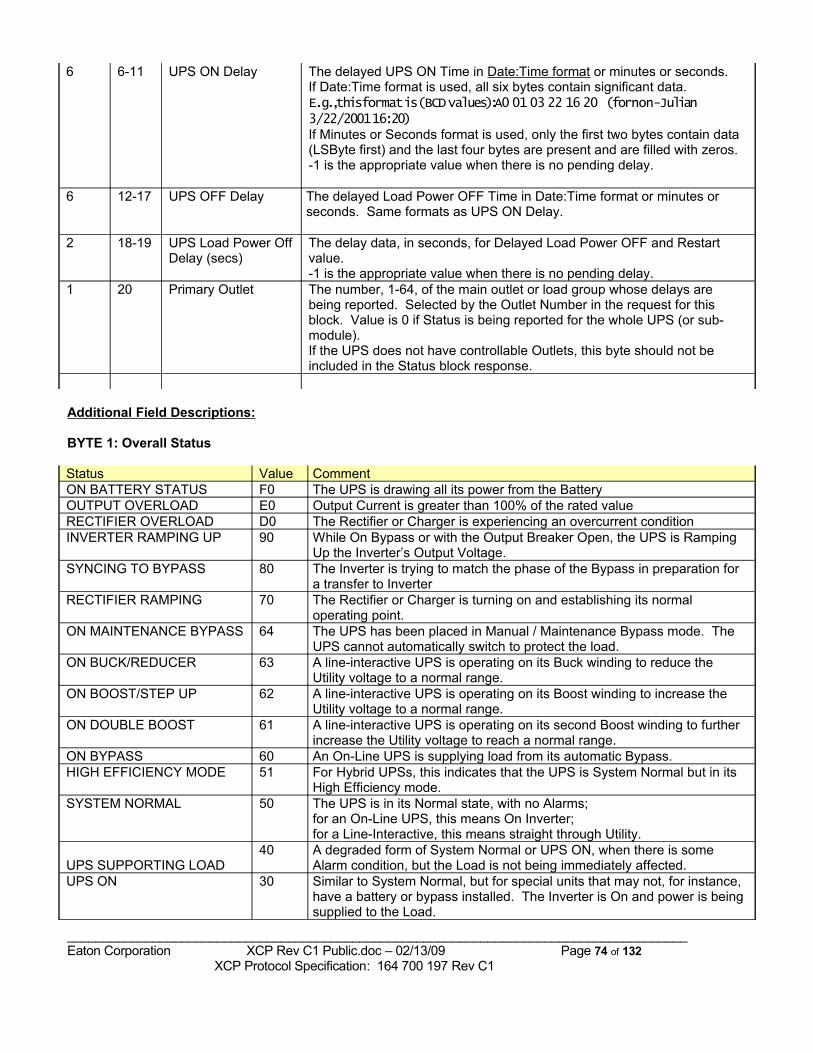
6 6-11 UPS ON Delay The delayed UPS ON Time in Date:Time format or minutes or seconds. If Date:Time format is used, all six bytes contain significant data.E.g., this format is (BCD values): A0 01 03 22 16 20 (for non-Julian 3/22/2001 16:20) If Minutes or Seconds format is used, only the first two bytes contain data (LSByte first) and the last four bytes are present and are filled with zeros. -1 is the appropriate value when there is no pending delay.
6 12-17 UPS OFF Delay The delayed Load Power OFF Time in Date:Time format or minutes or seconds. Same formats as UPS ON Delay.
2 18-19 UPS Load Power Off Delay (secs)
The delay data, in seconds, for Delayed Load Power OFF and Restart value. -1 is the appropriate value when there is no pending delay.
1 20 Primary Outlet The number, 1-64, of the main outlet or load group whose delays are being reported. Selected by the Outlet Number in the request for this block. Value is 0 if Status is being reported for the whole UPS (or sub-module).If the UPS does not have controllable Outlets, this byte should not be included in the Status block response.
Additional Field Descriptions:
BYTE 1: Overall Status
Status Value CommentON BATTERY STATUS F0 The UPS is drawing all its power from the BatteryOUTPUT OVERLOAD E0 Output Current is greater than 100% of the rated value RECTIFIER OVERLOAD D0 The Rectifier or Charger is experiencing an overcurrent conditionINVERTER RAMPING UP 90 While On Bypass or with the Output Breaker Open, the UPS is Ramping
Up the Inverter’s Output Voltage.SYNCING TO BYPASS 80 The Inverter is trying to match the phase of the Bypass in preparation for
a transfer to InverterRECTIFIER RAMPING 70 The Rectifier or Charger is turning on and establishing its normal
operating point.ON MAINTENANCE BYPASS 64 The UPS has been placed in Manual / Maintenance Bypass mode. The
UPS cannot automatically switch to protect the load.ON BUCK/REDUCER 63 A line-interactive UPS is operating on its Buck winding to reduce the
Utility voltage to a normal range.ON BOOST/STEP UP 62 A line-interactive UPS is operating on its Boost winding to increase the
Utility voltage to a normal range.ON DOUBLE BOOST 61 A line-interactive UPS is operating on its second Boost winding to further
increase the Utility voltage to reach a normal range.ON BYPASS 60 An On-Line UPS is supplying load from its automatic Bypass.HIGH EFFICIENCY MODE 51 For Hybrid UPSs, this indicates that the UPS is System Normal but in its
High Efficiency mode.SYSTEM NORMAL 50 The UPS is in its Normal state, with no Alarms;
for an On-Line UPS, this means On Inverter; for a Line-Interactive, this means straight through Utility.
UPS SUPPORTING LOAD40 A degraded form of System Normal or UPS ON, when there is some
Alarm condition, but the Load is not being immediately affected.UPS ON 30 Similar to System Normal, but for special units that may not, for instance,
have a battery or bypass installed. The Inverter is On and power is being supplied to the Load.
_______________________________________________________________________________________Eaton Corporation XCP Rev C1 Public.doc – 02/13/09 Page 74 of 132 XCP Protocol Specification: 164 700 197 Rev C1
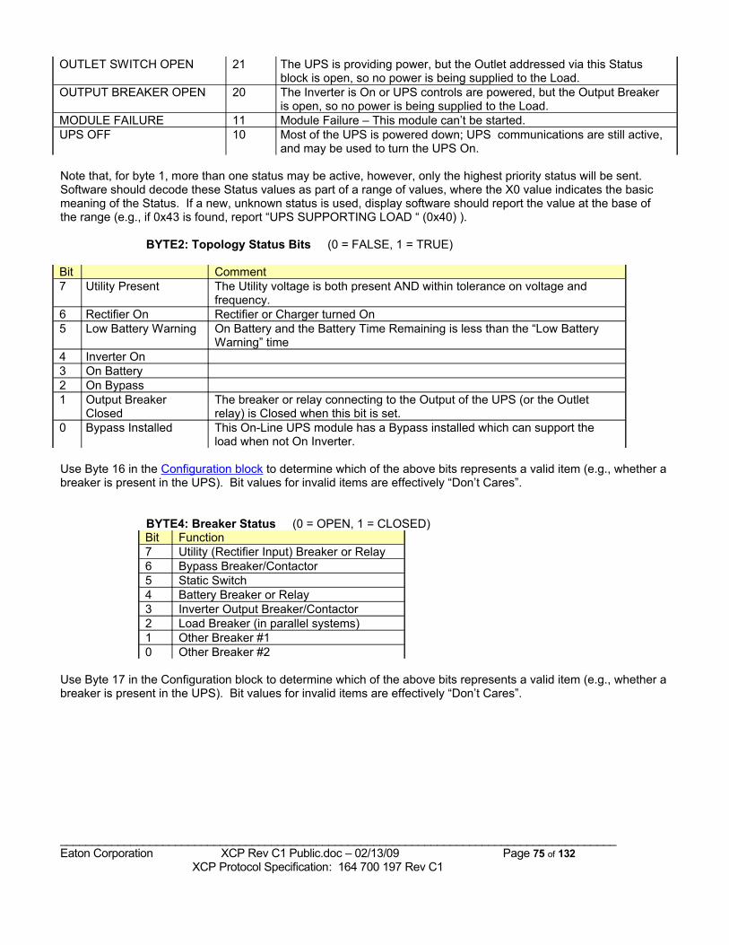
OUTLET SWITCH OPEN 21 The UPS is providing power, but the Outlet addressed via this Status block is open, so no power is being supplied to the Load.
OUTPUT BREAKER OPEN 20 The Inverter is On or UPS controls are powered, but the Output Breaker is open, so no power is being supplied to the Load.
MODULE FAILURE 11 Module Failure – This module can’t be started.UPS OFF 10 Most of the UPS is powered down; UPS communications are still active,
and may be used to turn the UPS On.
Note that, for byte 1, more than one status may be active, however, only the highest priority status will be sent. Software should decode these Status values as part of a range of values, where the X0 value indicates the basic meaning of the Status. If a new, unknown status is used, display software should report the value at the base of the range (e.g., if 0x43 is found, report “UPS SUPPORTING LOAD “ (0x40) ).
BYTE2: Topology Status Bits (0 = FALSE, 1 = TRUE) Bit Comment7 Utility Present The Utility voltage is both present AND within tolerance on voltage and
frequency. 6 Rectifier On Rectifier or Charger turned On5 Low Battery Warning On Battery and the Battery Time Remaining is less than the “Low Battery
Warning” time4 Inverter On3 On Battery2 On Bypass1 Output Breaker
ClosedThe breaker or relay connecting to the Output of the UPS (or the Outlet relay) is Closed when this bit is set.
0 Bypass Installed This On-Line UPS module has a Bypass installed which can support the load when not On Inverter.
Use Byte 16 in the Configuration block to determine which of the above bits represents a valid item (e.g., whether a breaker is present in the UPS). Bit values for invalid items are effectively “Don’t Cares”.
BYTE4: Breaker Status (0 = OPEN, 1 = CLOSED)Bit Function7 Utility (Rectifier Input) Breaker or Relay6 Bypass Breaker/Contactor5 Static Switch4 Battery Breaker or Relay3 Inverter Output Breaker/Contactor2 Load Breaker (in parallel systems)1 Other Breaker #10 Other Breaker #2
Use Byte 17 in the Configuration block to determine which of the above bits represents a valid item (e.g., whether a breaker is present in the UPS). Bit values for invalid items are effectively “Don’t Cares”.
_______________________________________________________________________________________Eaton Corporation XCP Rev C1 Public.doc – 02/13/09 Page 75 of 132 XCP Protocol Specification: 164 700 197 Rev C1
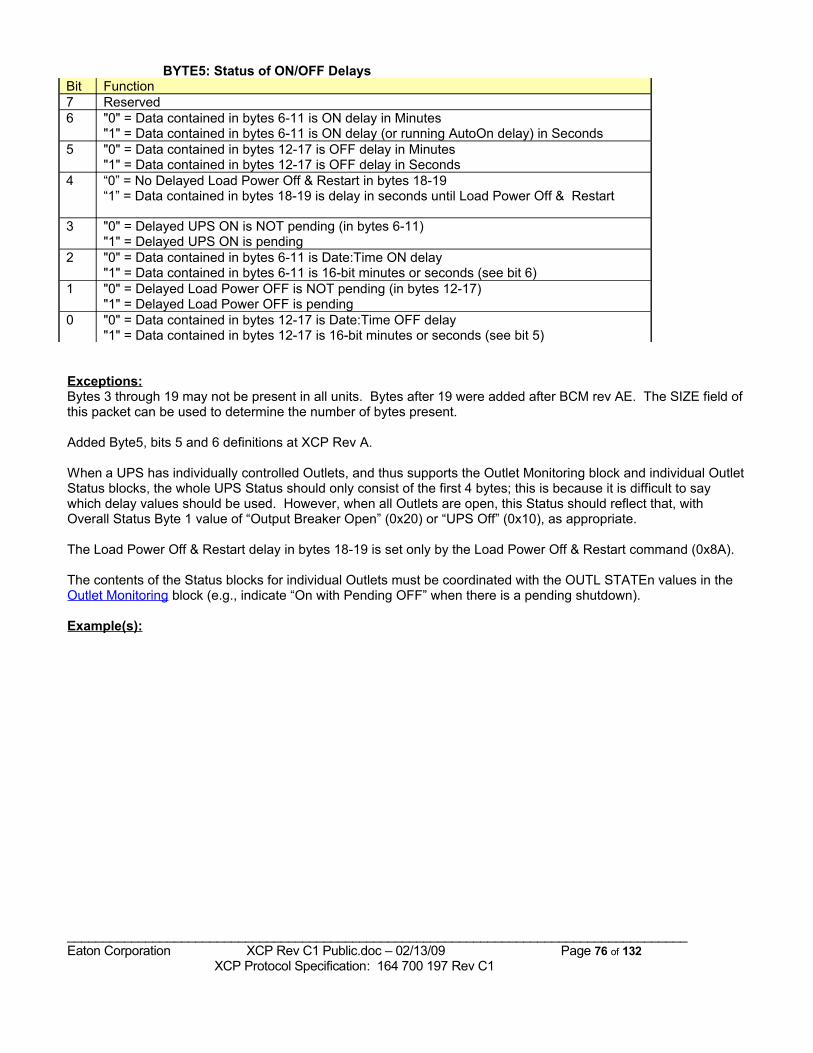
BYTE5: Status of ON/OFF Delays Bit Function7 Reserved6 "0" = Data contained in bytes 6-11 is ON delay in Minutes
"1" = Data contained in bytes 6-11 is ON delay (or running AutoOn delay) in Seconds 5 "0" = Data contained in bytes 12-17 is OFF delay in Minutes
"1" = Data contained in bytes 12-17 is OFF delay in Seconds4 “0” = No Delayed Load Power Off & Restart in bytes 18-19
“1” = Data contained in bytes 18-19 is delay in seconds until Load Power Off & Restart
3 "0" = Delayed UPS ON is NOT pending (in bytes 6-11)"1" = Delayed UPS ON is pending
2 "0" = Data contained in bytes 6-11 is Date:Time ON delay"1" = Data contained in bytes 6-11 is 16-bit minutes or seconds (see bit 6)
1 "0" = Delayed Load Power OFF is NOT pending (in bytes 12-17)"1" = Delayed Load Power OFF is pending
0 "0" = Data contained in bytes 12-17 is Date:Time OFF delay"1" = Data contained in bytes 12-17 is 16-bit minutes or seconds (see bit 5)
Exceptions:Bytes 3 through 19 may not be present in all units. Bytes after 19 were added after BCM rev AE. The SIZE field of this packet can be used to determine the number of bytes present.
Added Byte5, bits 5 and 6 definitions at XCP Rev A.
When a UPS has individually controlled Outlets, and thus supports the Outlet Monitoring block and individual Outlet Status blocks, the whole UPS Status should only consist of the first 4 bytes; this is because it is difficult to say which delay values should be used. However, when all Outlets are open, this Status should reflect that, with Overall Status Byte 1 value of “Output Breaker Open” (0x20) or “UPS Off” (0x10), as appropriate.
The Load Power Off & Restart delay in bytes 18-19 is set only by the Load Power Off & Restart command (0x8A).
The contents of the Status blocks for individual Outlets must be coordinated with the OUTL STATEn values in the Outlet Monitoring block (e.g., indicate “On with Pending OFF” when there is a pending shutdown).
Example(s):
_______________________________________________________________________________________Eaton Corporation XCP Rev C1 Public.doc – 02/13/09 Page 76 of 132 XCP Protocol Specification: 164 700 197 Rev C1
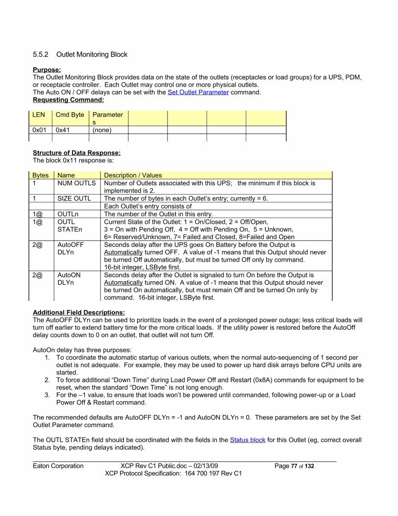
5.5.2 Outlet Monitoring Block
Purpose:The Outlet Monitoring Block provides data on the state of the outlets (receptacles or load groups) for a UPS, PDM, or receptacle controller. Each Outlet may control one or more physical outlets.The Auto ON / OFF delays can be set with the Set Outlet Parameter command.Requesting Command:
LEN Cmd Byte Parameters
0x01 0x41 (none)
Structure of Data Response:The block 0x11 response is:
Bytes Name Description / Values1 NUM OUTLS Number of Outlets associated with this UPS; the minimum if this block is
implemented is 2.1 SIZE OUTL The number of bytes in each Outlet’s entry; currently = 6.
Each Outlet’s entry consists of1@ OUTLn The number of the Outlet in this entry.1@ OUTL
STATEnCurrent State of the Outlet: 1 = On/Closed, 2 = Off/Open, 3 = On with Pending Off, 4 = Off with Pending On, 5 = Unknown, 6= Reserved/Unknown, 7= Failed and Closed, 8=Failed and Open
2@ AutoOFF DLYn
Seconds delay after the UPS goes On Battery before the Output is Automatically turned OFF. A value of -1 means that this Output should never be turned Off automatically, but must be turned Off only by command.16-bit integer, LSByte first.
2@ AutoON DLYn
Seconds delay after the Outlet is signaled to turn On before the Output is Automatically turned ON. A value of -1 means that this Output should never be turned On automatically, but must remain Off and be turned On only by command. 16-bit integer, LSByte first.
Additional Field Descriptions:The AutoOFF DLYn can be used to prioritize loads in the event of a prolonged power outage; less critical loads will turn off earlier to extend battery time for the more critical loads. If the utility power is restored before the AutoOff delay counts down to 0 on an outlet, that outlet will not turn Off.
AutoOn delay has three purposes:1. To coordinate the automatic startup of various outlets, when the normal auto-sequencing of 1 second per
outlet is not adequate. For example, they may be used to power up hard disk arrays before CPU units are started.
2. To force additional “Down Time” during Load Power Off and Restart (0x8A) commands for equipment to be reset, when the standard “Down Time” is not long enough.
3. For the –1 value, to ensure that loads won’t be powered until commanded, following power-up or a Load Power Off & Restart command.
The recommended defaults are AutoOFF DLYn = -1 and AutoON DLYn = 0. These parameters are set by the Set Outlet Parameter command.
The OUTL STATEn field should be coordinated with the fields in the Status block for this Outlet (eg, correct overall Status byte, pending delays indicated).
_______________________________________________________________________________________Eaton Corporation XCP Rev C1 Public.doc – 02/13/09 Page 77 of 132 XCP Protocol Specification: 164 700 197 Rev C1
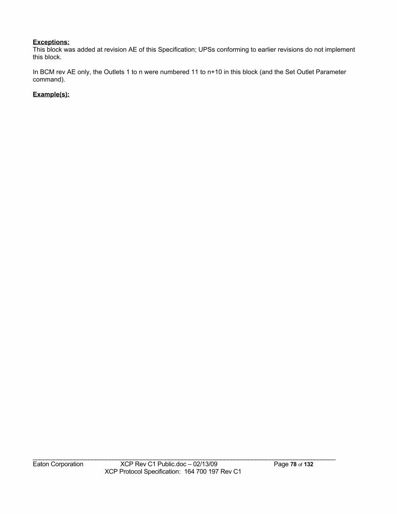
Exceptions:This block was added at revision AE of this Specification; UPSs conforming to earlier revisions do not implement this block.
In BCM rev AE only, the Outlets 1 to n were numbered 11 to n+10 in this block (and the Set Outlet Parameter command).
Example(s):
_______________________________________________________________________________________Eaton Corporation XCP Rev C1 Public.doc – 02/13/09 Page 78 of 132 XCP Protocol Specification: 164 700 197 Rev C1
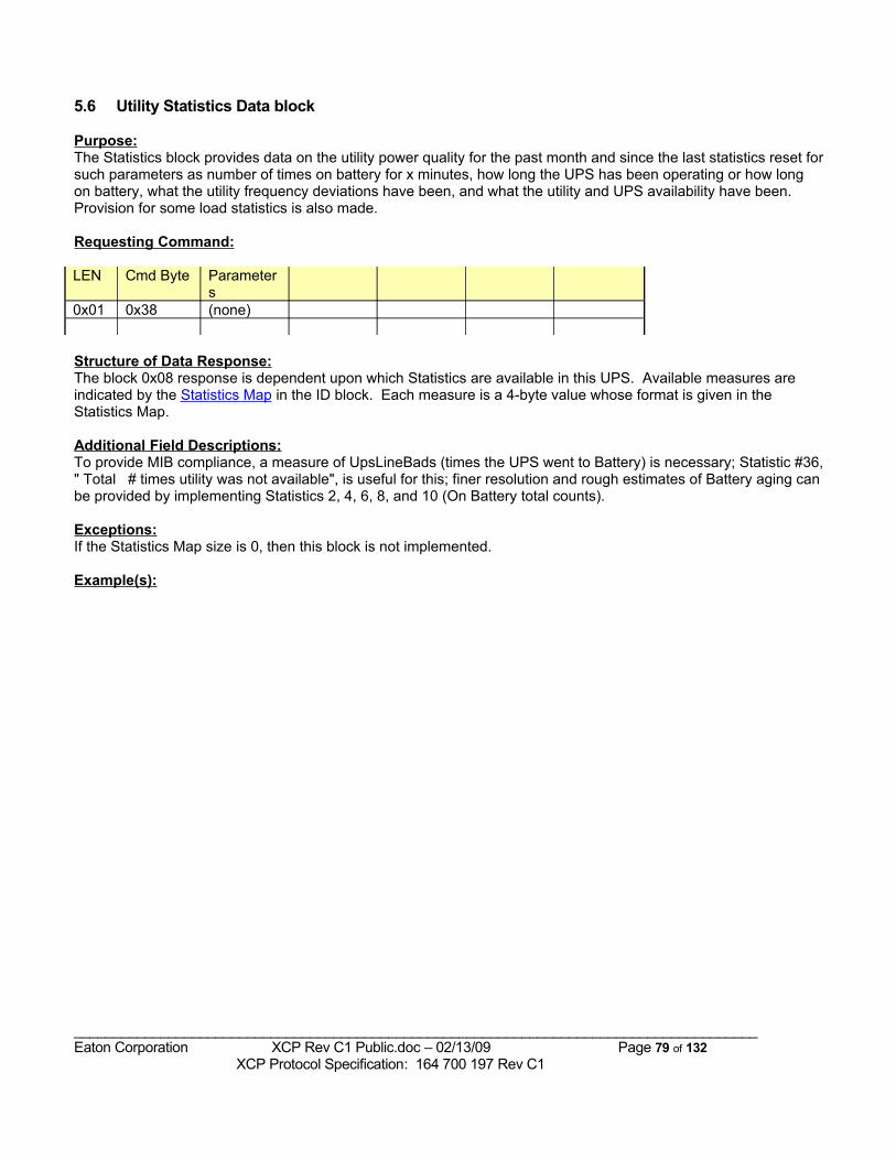
5.6 Utility Statistics Data block
Purpose:The Statistics block provides data on the utility power quality for the past month and since the last statistics reset for such parameters as number of times on battery for x minutes, how long the UPS has been operating or how long on battery, what the utility frequency deviations have been, and what the utility and UPS availability have been. Provision for some load statistics is also made.
Requesting Command:
LEN Cmd Byte Parameters
0x01 0x38 (none)
Structure of Data Response:The block 0x08 response is dependent upon which Statistics are available in this UPS. Available measures are indicated by the Statistics Map in the ID block. Each measure is a 4-byte value whose format is given in the Statistics Map.
Additional Field Descriptions:To provide MIB compliance, a measure of UpsLineBads (times the UPS went to Battery) is necessary; Statistic #36, " Total # times utility was not available", is useful for this; finer resolution and rough estimates of Battery aging can be provided by implementing Statistics 2, 4, 6, 8, and 10 (On Battery total counts).
Exceptions:If the Statistics Map size is 0, then this block is not implemented.
Example(s):
_______________________________________________________________________________________Eaton Corporation XCP Rev C1 Public.doc – 02/13/09 Page 79 of 132 XCP Protocol Specification: 164 700 197 Rev C1
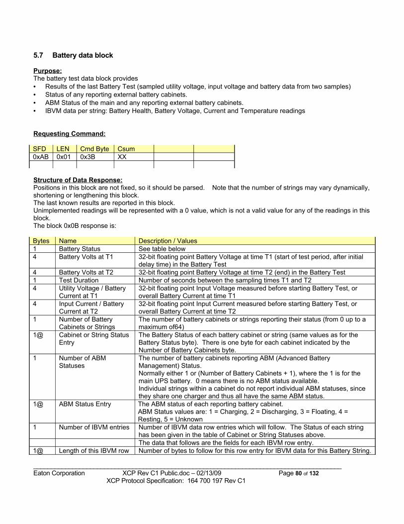
5.7 Battery data block
Purpose:The battery test data block provides • Results of the last Battery Test (sampled utility voltage, input voltage and battery data from two samples)• Status of any reporting external battery cabinets. • ABM Status of the main and any reporting external battery cabinets.• IBVM data per string: Battery Health, Battery Voltage, Current and Temperature readings
Requesting Command:
SFD LEN Cmd Byte Csum0xAB 0x01 0x3B XX
Structure of Data Response:Positions in this block are not fixed, so it should be parsed. Note that the number of strings may vary dynamically, shortening or lengthening this block. The last known results are reported in this block.Unimplemented readings will be represented with a 0 value, which is not a valid value for any of the readings in this block.The block 0x0B response is:
Bytes Name Description / Values1 Battery Status See table below4 Battery Volts at T1 32-bit floating point Battery Voltage at time T1 (start of test period, after initial
delay time) in the Battery Test4 Battery Volts at T2 32-bit floating point Battery Voltage at time T2 (end) in the Battery Test1 Test Duration Number of seconds between the sampling times T1 and T24 Utility Voltage / Battery
Current at T132-bit floating point Input Voltage measured before starting Battery Test, or overall Battery Current at time T1
4 Input Current / Battery Current at T2
32-bit floating point Input Current measured before starting Battery Test, or overall Battery Current at time T2
1 Number of Battery Cabinets or Strings
The number of battery cabinets or strings reporting their status (from 0 up to a maximum of64)
1@ Cabinet or String Status Entry
The Battery Status of each battery cabinet or string (same values as for the Battery Status byte). There is one byte for each cabinet indicated by the Number of Battery Cabinets byte.
1 Number of ABM Statuses
The number of battery cabinets reporting ABM (Advanced Battery Management) Status.Normally either 1 or (Number of Battery Cabinets + 1), where the 1 is for the main UPS battery. 0 means there is no ABM status available.Individual strings within a cabinet do not report individual ABM statuses, since they share one charger and thus all have the same ABM status.
1@ ABM Status Entry The ABM status of each reporting battery cabinet. ABM Status values are: 1 = Charging, 2 = Discharging, 3 = Floating, 4 = Resting, 5 = Unknown
1 Number of IBVM entries Number of IBVM data row entries which will follow. The Status of each string has been given in the table of Cabinet or String Statuses above.The data that follows are the fields for each IBVM row entry.
1@ Length of this IBVM row Number of bytes to follow for this row entry for IBVM data for this Battery String.
_______________________________________________________________________________________Eaton Corporation XCP Rev C1 Public.doc – 02/13/09 Page 80 of 132 XCP Protocol Specification: 164 700 197 Rev C1
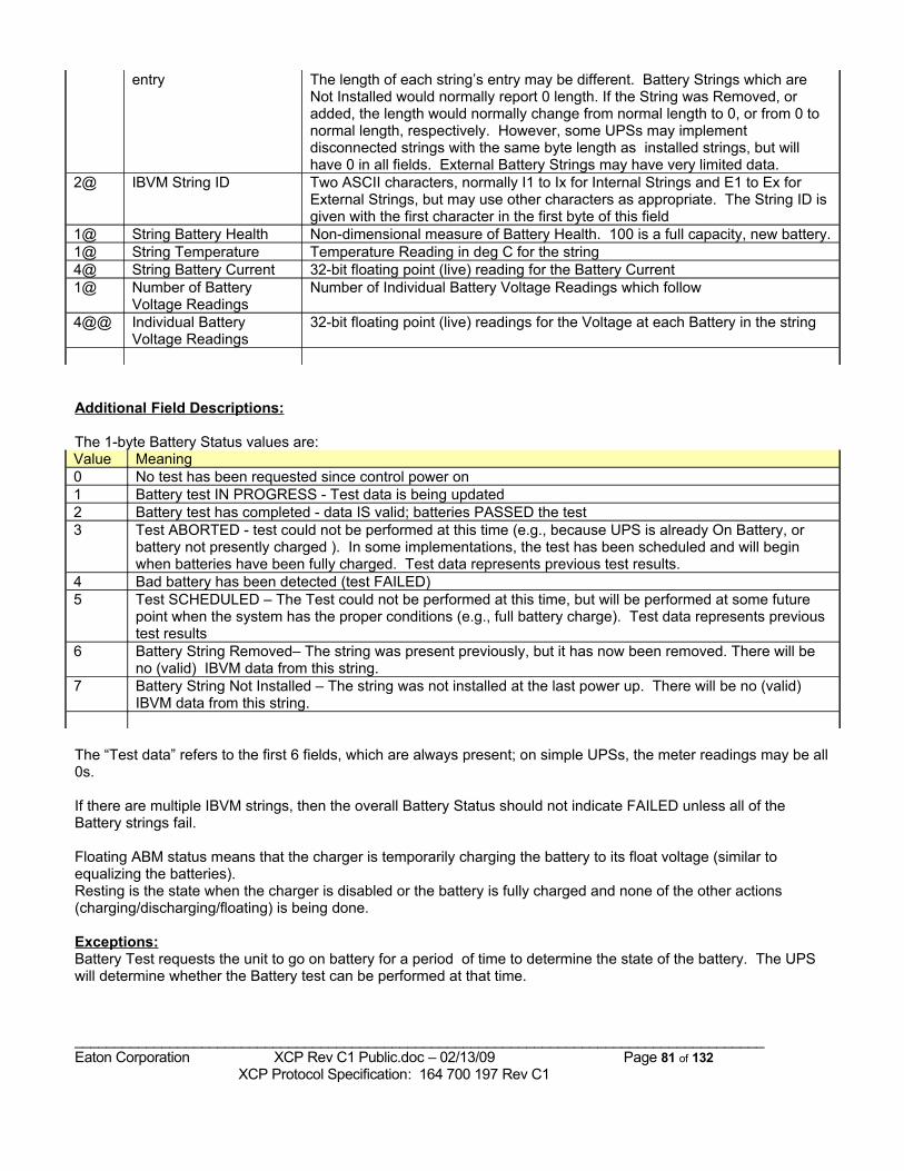
entry The length of each string’s entry may be different. Battery Strings which are Not Installed would normally report 0 length. If the String was Removed, or added, the length would normally change from normal length to 0, or from 0 to normal length, respectively. However, some UPSs may implement disconnected strings with the same byte length as installed strings, but will have 0 in all fields. External Battery Strings may have very limited data.
2@ IBVM String ID Two ASCII characters, normally I1 to Ix for Internal Strings and E1 to Ex for External Strings, but may use other characters as appropriate. The String ID is given with the first character in the first byte of this field
1@ String Battery Health Non-dimensional measure of Battery Health. 100 is a full capacity, new battery.1@ String Temperature Temperature Reading in deg C for the string4@ String Battery Current 32-bit floating point (live) reading for the Battery Current1@ Number of Battery
Voltage ReadingsNumber of Individual Battery Voltage Readings which follow
4@@ Individual Battery Voltage Readings
32-bit floating point (live) readings for the Voltage at each Battery in the string
Additional Field Descriptions:
The 1-byte Battery Status values are:Value Meaning0 No test has been requested since control power on1 Battery test IN PROGRESS - Test data is being updated2 Battery test has completed - data IS valid; batteries PASSED the test3 Test ABORTED - test could not be performed at this time (e.g., because UPS is already On Battery, or
battery not presently charged ). In some implementations, the test has been scheduled and will begin when batteries have been fully charged. Test data represents previous test results.
4 Bad battery has been detected (test FAILED)5 Test SCHEDULED – The Test could not be performed at this time, but will be performed at some future
point when the system has the proper conditions (e.g., full battery charge). Test data represents previous test results
6 Battery String Removed– The string was present previously, but it has now been removed. There will be no (valid) IBVM data from this string.
7 Battery String Not Installed – The string was not installed at the last power up. There will be no (valid) IBVM data from this string.
The “Test data” refers to the first 6 fields, which are always present; on simple UPSs, the meter readings may be all 0s.
If there are multiple IBVM strings, then the overall Battery Status should not indicate FAILED unless all of the Battery strings fail.
Floating ABM status means that the charger is temporarily charging the battery to its float voltage (similar to equalizing the batteries). Resting is the state when the charger is disabled or the battery is fully charged and none of the other actions (charging/discharging/floating) is being done.
Exceptions:Battery Test requests the unit to go on battery for a period of time to determine the state of the battery. The UPS will determine whether the Battery test can be performed at that time.
_______________________________________________________________________________________Eaton Corporation XCP Rev C1 Public.doc – 02/13/09 Page 81 of 132 XCP Protocol Specification: 164 700 197 Rev C1
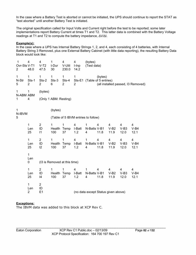
In the case where a Battery Test is aborted or cannot be initiated, the UPS should continue to report the STAT as “test aborted” until another Battery Test is initiated.
The original specification called for Input Volts and Current right before the test to be reported; some later implementations report Battery Current at times T1 and T2. This latter data is combined with the Battery Voltage readings at T1 and T2 to compute the battery impedance, ∆V/∆I.
Example(s):In the case where a UPS has Internal Battery Strings 1, 2, and 4, each consisting of 4 batteries, with Internal Battery String 3 Removed, plus one External Battery Cabinet (with little data reporting), the resulting Battery Data block would look like:
1 4 4 1 4 4 (bytes)Ovr-Sts V-T1 V-T2 t-Dur V-Util I-Inp (Test data)2 48.0 47.5 30 230.0 14.2
1 1 1 1 1 1 (bytes)N-Str Sts-1 Sts-2 Sts-3 Sts-4 Sts-E1 (Table of 5 entries)5 2 2 6 2 2 (all installed passed, I3 Removed)
1 1 (bytes)N-ABM ABM1 4 (Only 1 ABM: Resting)
1 (bytes)N-IBVM5 (Table of 5 IBVM entries to follow)
1 2 1 1 4 1 4 4 4 4Len ID Health Temp I-Batt N-Batts V-B1 V-B2 V-B3 V-B425 I1 100 37 1.2 4 11.8 11.9 12.0 12.1
1 2 1 1 4 1 4 4 4 4Len ID Health Temp I-Batt N-Batts V-B1 V-B2 V-B3 V-B425 I2 100 37 1.2 4 11.8 11.9 12.0 12.1
1Len0 (I3 is Removed at this time)
1 2 1 1 4 1 4 4 4 4Len ID Health Temp I-Batt N-Batts V-B1 V-B2 V-B3 V-B425 I4 100 37 1.2 4 11.8 11.9 12.0 12.1
1 2Len ID2 E1 (no data except Status given above)
Exceptions:The IBVM data was added to this block at XCP Rev C.
_______________________________________________________________________________________Eaton Corporation XCP Rev C1 Public.doc – 02/13/09 Page 82 of 132 XCP Protocol Specification: 164 700 197 Rev C1

5.8 Test Results Data Block
Purpose:The Test Results Data block provides results of any requested Systems Tests. These tests are initiated by the Request Systems Test command.
Requesting Command:
SFD LEN Cmd Byte Csum0xAB 0x01 0x3F XX
Structure of Data Response:This block should be parsed, as it may contain information from more than one module. The last known results are reported in this block. Unimplemented readings will be represented with a 0 value, which is not a valid value for any of the readings in this block.The block 0x0F response is:
Bytes Name Description / Values1 Number of Modules The Number of Modules reporting results of Systems Tests (from 0 up to a
maximum of 16)1 Result Entry Length How many bytes reported below for each module’s results (currently only
two bytes are defined)1@ Test Results Status The Results of the Last Test run for each module. 1@ Number of Last Test The Test Number of the Last Test run for each module.
Additional Field Descriptions:
The 1-byte Test Results Status values are:Value Meaning0 No test has been requested since control power on1 Systems test IN PROGRESS - data is NOT valid2 Systems test PASSED 3 Test ABORTED - test could not be performed at this time (e.g., because UPS is On Battery)4 Systems Test FAILED)
The currently defined Test Numbers are:5.8.1.1.1.1.1 01: Initiate General Systems Test5.8.1.1.1.1.2 02: Schedule Battery Commissioning Test
5.8.1.1.1.1.3 03: Test Alternate AC Input04: Flash the Lights Test
Exceptions:In the case where a Systems Test was aborted or could not be initiated, the UPS should continue to report the Status as “test aborted” until another General Systems Test is initiated.
Example(s):
_______________________________________________________________________________________Eaton Corporation XCP Rev C1 Public.doc – 02/13/09 Page 83 of 132 XCP Protocol Specification: 164 700 197 Rev C1
6 Control and Configuration CommandsAll of the commands described in this section cause some action of the UPS. In this, they are different than the Data block requests described in the last section. Two other differences that apply to all these control commands, unless otherwise noted, are:
1. Each of these commands must be immediately preceded by an authorization command (either standard Auth block or, for ACM or NetBCM, Password Authorization block.
2. The response to each of these commands is the Command Acknowledge (ACK) block.
6.1 Load Control CommandsThe Load Control commands are BRIEFLY described in this section. For full behavioral details, see document Outlet Control Logic.doc.The distinguishing features of these commands are: • used to turn the UPS On or Off, or put it On Bypass
• with or without delays
• delays in minutes or seconds or date & time
• with or without restart after the UPS turns Off
• action / countdown commences on command or automatically
• action directed to the whole UPS or to an individual Outlet (“Load Group”)
• whether or not the command can be aborted while counting down
• For Outlets, followed by optional AutoOn or sequence delay
Recommendations:1. For shutdown while On Battery, normally use the Delayed Load Power Off & Restart command, so the UPS will
automatically turn back On when utility power is restored.2. For scheduled shutdowns, use whichever commands are (most easily) implemented in the UPS:
Scheduled UPS Off in “n” Minutes and Scheduled UPS On in “n” Minutes Scheduled UPS Off and On at Date & Time
3. For quickly turning the UPS On or Off, use the immediate UPS On or Off commands. These are basically special cases of the Scheduled On / Off commands, with delay of 0.
4. The UPS should not automatically restart after executing an immediate or Scheduled Off command; the intent is to turn the UPS Off until commanded to turn it back On. However, if an On delay is scheduled, the UPS will come back On after that delay elapses.
5. For controlling individual Outlets, on UPSs which permit this control, the best approach is to use the above commands with the optional Outlet address field. However, some UPSs may have Outlets that can only be controlled via the Set Outlet Parameter command.
6. For UPSs with Outlet control, not specifying an Outlet address or specifying an Outlet address of 255 directs the UPS to apply the command to ALL Outlets.
7. The Conditional Delayed Load Power Off & Restart command is not recommended for shutdown software, and it is not widely implemented.
The results of these commands, and any pending On/Off actions, may be monitored via the Status block or the Outlet Monitoring block.
_______________________________________________________________________________________Eaton Corporation XCP Rev C1 Public.doc – 02/13/09 Page 84 of 132 XCP Protocol Specification: 164 700 197 Rev C1
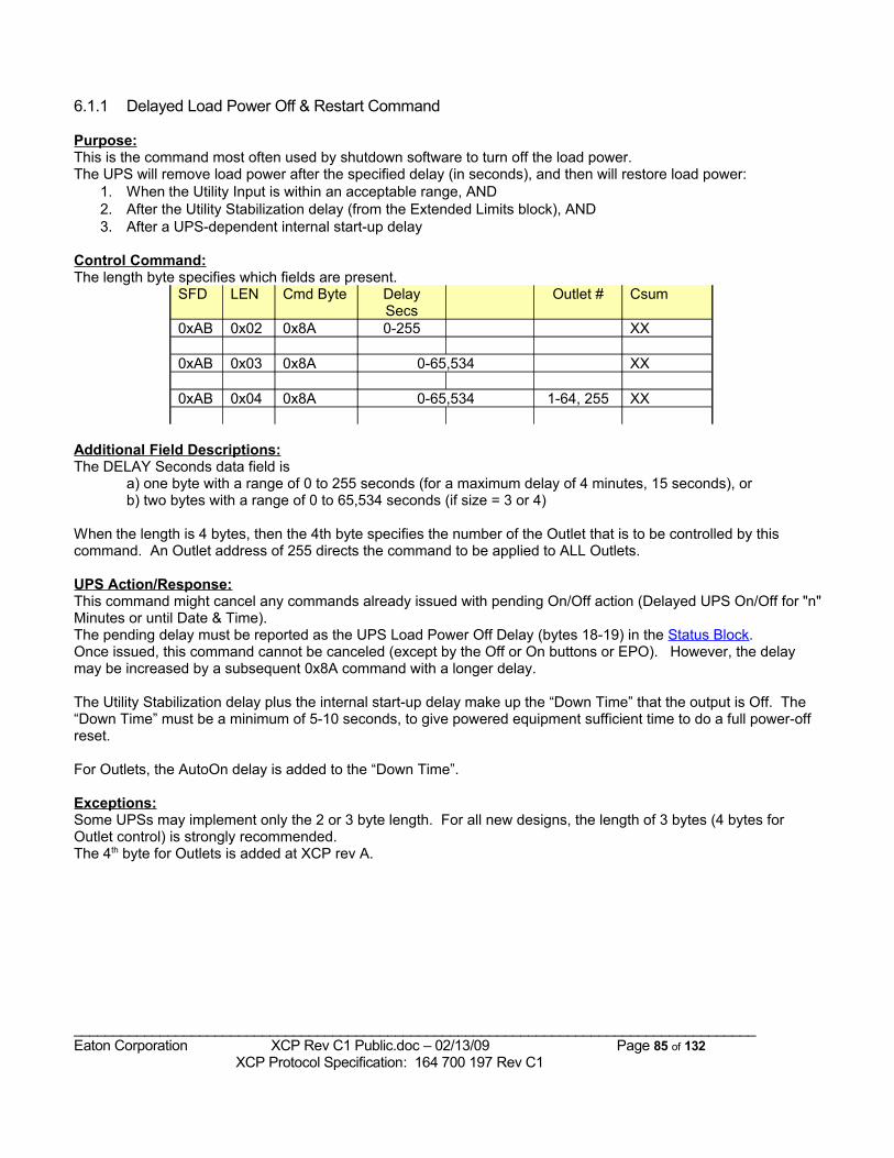
6.1.1 Delayed Load Power Off & Restart Command
Purpose:This is the command most often used by shutdown software to turn off the load power.The UPS will remove load power after the specified delay (in seconds), and then will restore load power:
1. When the Utility Input is within an acceptable range, AND2. After the Utility Stabilization delay (from the Extended Limits block), AND3. After a UPS-dependent internal start-up delay
Control Command:The length byte specifies which fields are present.
SFD LEN Cmd Byte Delay Secs
Outlet # Csum
0xAB 0x02 0x8A 0-255 XX
0xAB 0x03 0x8A 0-65,534 XX
0xAB 0x04 0x8A 0-65,534 1-64, 255 XX
Additional Field Descriptions:The DELAY Seconds data field is
a) one byte with a range of 0 to 255 seconds (for a maximum delay of 4 minutes, 15 seconds), or b) two bytes with a range of 0 to 65,534 seconds (if size = 3 or 4)
When the length is 4 bytes, then the 4th byte specifies the number of the Outlet that is to be controlled by this command. An Outlet address of 255 directs the command to be applied to ALL Outlets.
UPS Action/Response:This command might cancel any commands already issued with pending On/Off action (Delayed UPS On/Off for "n" Minutes or until Date & Time). The pending delay must be reported as the UPS Load Power Off Delay (bytes 18-19) in the Status Block. Once issued, this command cannot be canceled (except by the Off or On buttons or EPO). However, the delay may be increased by a subsequent 0x8A command with a longer delay.
The Utility Stabilization delay plus the internal start-up delay make up the “Down Time” that the output is Off. The “Down Time” must be a minimum of 5-10 seconds, to give powered equipment sufficient time to do a full power-off reset.
For Outlets, the AutoOn delay is added to the “Down Time”.
Exceptions:Some UPSs may implement only the 2 or 3 byte length. For all new designs, the length of 3 bytes (4 bytes for Outlet control) is strongly recommended.The 4th byte for Outlets is added at XCP rev A.
_______________________________________________________________________________________Eaton Corporation XCP Rev C1 Public.doc – 02/13/09 Page 85 of 132 XCP Protocol Specification: 164 700 197 Rev C1
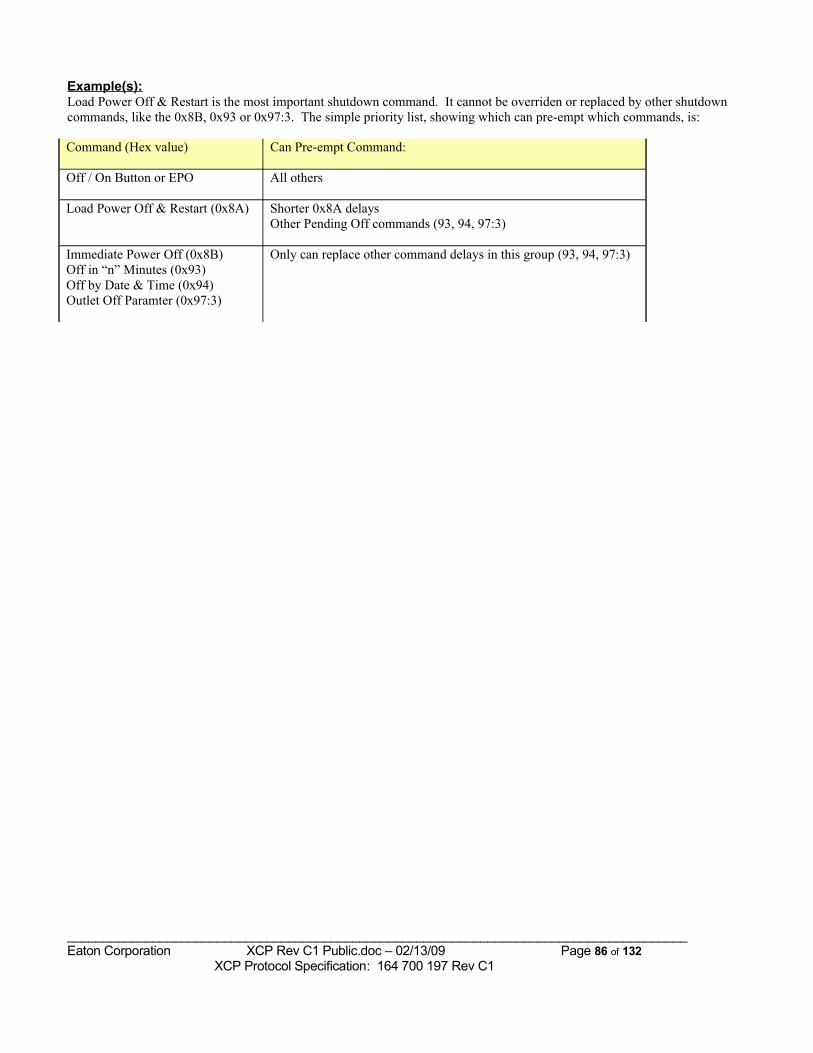
Example(s):Load Power Off & Restart is the most important shutdown command. It cannot be overriden or replaced by other shutdown commands, like the 0x8B, 0x93 or 0x97:3. The simple priority list, showing which can pre-empt which commands, is:
Command (Hex value) Can Pre-empt Command:
Off / On Button or EPO All others
Load Power Off & Restart (0x8A) Shorter 0x8A delaysOther Pending Off commands (93, 94, 97:3)
Immediate Power Off (0x8B)Off in “n” Minutes (0x93)Off by Date & Time (0x94)Outlet Off Paramter (0x97:3)
Only can replace other command delays in this group (93, 94, 97:3)
_______________________________________________________________________________________Eaton Corporation XCP Rev C1 Public.doc – 02/13/09 Page 86 of 132 XCP Protocol Specification: 164 700 197 Rev C1
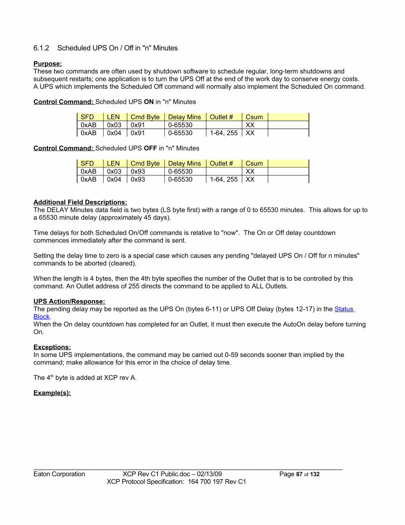
6.1.2 Scheduled UPS On / Off in "n" Minutes
Purpose:These two commands are often used by shutdown software to schedule regular, long-term shutdowns and subsequent restarts; one application is to turn the UPS Off at the end of the work day to conserve energy costs. A UPS which implements the Scheduled Off command will normally also implement the Scheduled On command.
Control Command: Scheduled UPS ON in "n" Minutes
SFD LEN Cmd Byte Delay Mins Outlet # Csum0xAB 0x03 0x91 0-65530 XX0xAB 0x04 0x91 0-65530 1-64, 255 XX
Control Command: Scheduled UPS OFF in "n" Minutes
SFD LEN Cmd Byte Delay Mins Outlet # Csum0xAB 0x03 0x93 0-65530 XX0xAB 0x04 0x93 0-65530 1-64, 255 XX
Additional Field Descriptions:The DELAY Minutes data field is two bytes (LS byte first) with a range of 0 to 65530 minutes. This allows for up to a 65530 minute delay (approximately 45 days).
Time delays for both Scheduled On/Off commands is relative to "now". The On or Off delay countdown commences immediately after the command is sent.
Setting the delay time to zero is a special case which causes any pending "delayed UPS On / Off for n minutes" commands to be aborted (cleared).
When the length is 4 bytes, then the 4th byte specifies the number of the Outlet that is to be controlled by this command. An Outlet address of 255 directs the command to be applied to ALL Outlets.
UPS Action/Response:The pending delay may be reported as the UPS On (bytes 6-11) or UPS Off Delay (bytes 12-17) in the Status Block. When the On delay countdown has completed for an Outlet, it must then execute the AutoOn delay before turning On.
Exceptions:In some UPS implementations, the command may be carried out 0-59 seconds sooner than implied by the command; make allowance for this error in the choice of delay time.
The 4th byte is added at XCP rev A.
Example(s):
_______________________________________________________________________________________Eaton Corporation XCP Rev C1 Public.doc – 02/13/09 Page 87 of 132 XCP Protocol Specification: 164 700 197 Rev C1
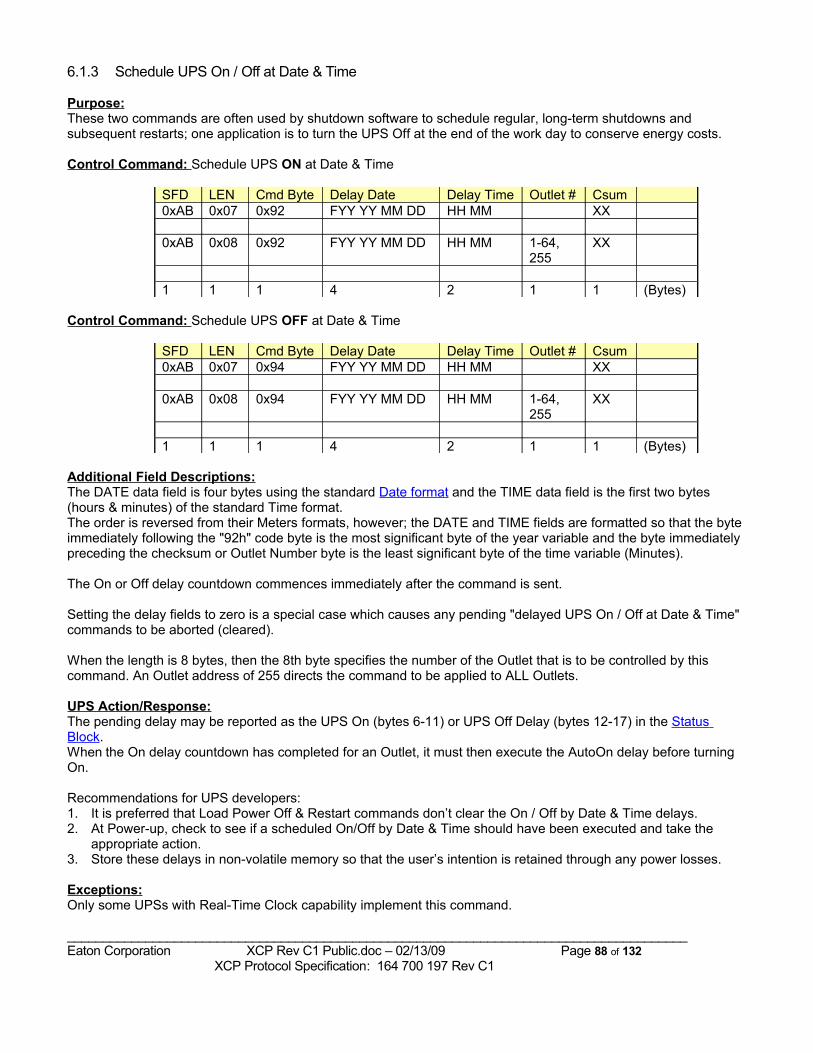
6.1.3 Schedule UPS On / Off at Date & Time
Purpose:These two commands are often used by shutdown software to schedule regular, long-term shutdowns and subsequent restarts; one application is to turn the UPS Off at the end of the work day to conserve energy costs.
Control Command: Schedule UPS ON at Date & Time
SFD LEN Cmd Byte Delay Date Delay Time Outlet # Csum0xAB 0x07 0x92 FYY YY MM DD HH MM XX
0xAB 0x08 0x92 FYY YY MM DD HH MM 1-64, 255
XX
1 1 1 4 2 1 1 (Bytes)
Control Command: Schedule UPS OFF at Date & Time
SFD LEN Cmd Byte Delay Date Delay Time Outlet # Csum0xAB 0x07 0x94 FYY YY MM DD HH MM XX
0xAB 0x08 0x94 FYY YY MM DD HH MM 1-64, 255
XX
1 1 1 4 2 1 1 (Bytes)
Additional Field Descriptions:The DATE data field is four bytes using the standard Date format and the TIME data field is the first two bytes (hours & minutes) of the standard Time format. The order is reversed from their Meters formats, however; the DATE and TIME fields are formatted so that the byte immediately following the "92h" code byte is the most significant byte of the year variable and the byte immediately preceding the checksum or Outlet Number byte is the least significant byte of the time variable (Minutes).
The On or Off delay countdown commences immediately after the command is sent.
Setting the delay fields to zero is a special case which causes any pending "delayed UPS On / Off at Date & Time" commands to be aborted (cleared).
When the length is 8 bytes, then the 8th byte specifies the number of the Outlet that is to be controlled by this command. An Outlet address of 255 directs the command to be applied to ALL Outlets.
UPS Action/Response:The pending delay may be reported as the UPS On (bytes 6-11) or UPS Off Delay (bytes 12-17) in the Status Block. When the On delay countdown has completed for an Outlet, it must then execute the AutoOn delay before turning On.
Recommendations for UPS developers:1. It is preferred that Load Power Off & Restart commands don’t clear the On / Off by Date & Time delays.2. At Power-up, check to see if a scheduled On/Off by Date & Time should have been executed and take the
appropriate action. 3. Store these delays in non-volatile memory so that the user’s intention is retained through any power losses.
Exceptions:Only some UPSs with Real-Time Clock capability implement this command.
_______________________________________________________________________________________Eaton Corporation XCP Rev C1 Public.doc – 02/13/09 Page 88 of 132 XCP Protocol Specification: 164 700 197 Rev C1
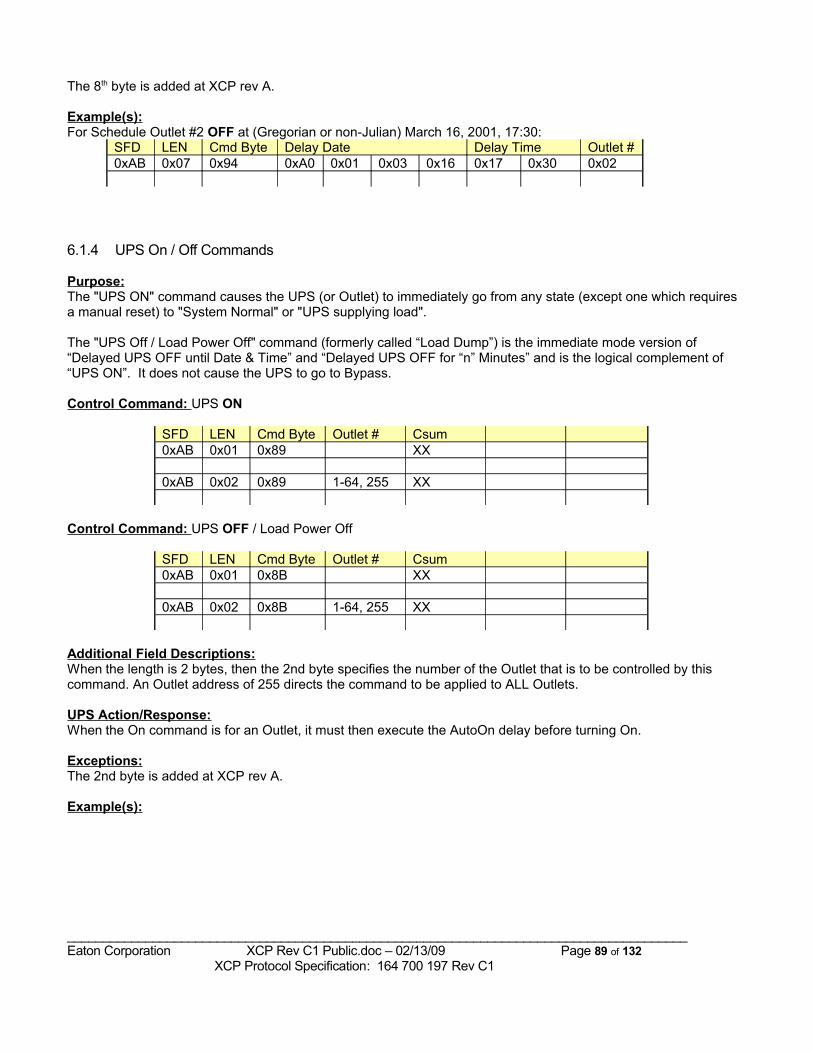
The 8th byte is added at XCP rev A.
Example(s):For Schedule Outlet #2 OFF at (Gregorian or non-Julian) March 16, 2001, 17:30:
SFD LEN Cmd Byte Delay Date Delay Time Outlet #0xAB 0x07 0x94 0xA0 0x01 0x03 0x16 0x17 0x30 0x02
6.1.4 UPS On / Off Commands
Purpose:The "UPS ON" command causes the UPS (or Outlet) to immediately go from any state (except one which requires a manual reset) to "System Normal" or "UPS supplying load".
The "UPS Off / Load Power Off" command (formerly called “Load Dump”) is the immediate mode version of “Delayed UPS OFF until Date & Time” and “Delayed UPS OFF for “n” Minutes” and is the logical complement of “UPS ON”. It does not cause the UPS to go to Bypass.
Control Command: UPS ON
SFD LEN Cmd Byte Outlet # Csum0xAB 0x01 0x89 XX
0xAB 0x02 0x89 1-64, 255 XX
Control Command: UPS OFF / Load Power Off
SFD LEN Cmd Byte Outlet # Csum0xAB 0x01 0x8B XX
0xAB 0x02 0x8B 1-64, 255 XX
Additional Field Descriptions:When the length is 2 bytes, then the 2nd byte specifies the number of the Outlet that is to be controlled by this command. An Outlet address of 255 directs the command to be applied to ALL Outlets.
UPS Action/Response:When the On command is for an Outlet, it must then execute the AutoOn delay before turning On.
Exceptions:The 2nd byte is added at XCP rev A.
Example(s):
_______________________________________________________________________________________Eaton Corporation XCP Rev C1 Public.doc – 02/13/09 Page 89 of 132 XCP Protocol Specification: 164 700 197 Rev C1
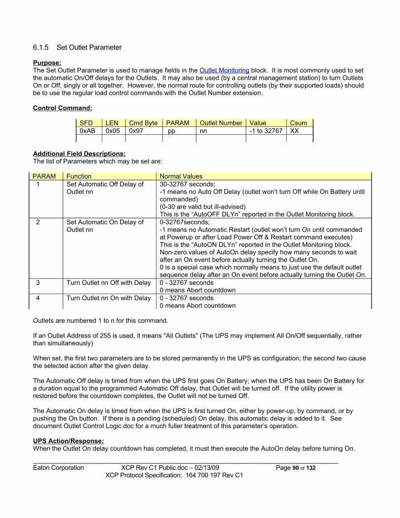
6.1.5 Set Outlet Parameter
Purpose:The Set Outlet Parameter is used to manage fields in the Outlet Monitoring block. It is most commonly used to set the automatic On/Off delays for the Outlets. It may also be used (by a central management station) to turn Outlets On or Off, singly or all together. However, the normal route for controlling outlets (by their supported loads) should be to use the regular load control commands with the Outlet Number extension.
Control Command:
SFD LEN Cmd Byte PARAM Outlet Number Value Csum0xAB 0x05 0x97 pp nn -1 to 32767 XX
Additional Field Descriptions:The list of Parameters which may be set are:
PARAM Function Normal Values 1 Set Automatic Off Delay of
Outlet nn 30-32767 seconds;-1 means no Auto Off Delay (outlet won’t turn Off while On Battery until commanded)(0-30 are valid but ill-advised)This is the “AutoOFF DLYn” reported in the Outlet Monitoring block.
2 Set Automatic On Delay of Outlet nn
0-32767seconds;-1 means no Automatic Restart (outlet won’t turn On until commanded at Powerup or after Load Power Off & Restart command executes)This is the “AutoON DLYn” reported in the Outlet Monitoring block.Non-zero values of AutoOn delay specify how many seconds to wait after an On event before actually turning the Outlet On.0 is a special case which normally means to just use the default outlet sequence delay after an On event before actually turning the Outlet On.
3 Turn Outlet nn Off with Delay 0 - 32767 seconds0 means Abort countdown
4 Turn Outlet nn On with Delay 0 - 32767 seconds0 means Abort countdown
Outlets are numbered 1 to n for this command.
If an Outlet Address of 255 is used, it means "All Outlets" (The UPS may implement All On/Off sequentially, rather than simultaneously)
When set, the first two parameters are to be stored permanently in the UPS as configuration; the second two cause the selected action after the given delay.
The Automatic Off delay is timed from when the UPS first goes On Battery; when the UPS has been On Battery for a duration equal to the programmed Automatic Off delay, that Outlet will be turned off. If the utility power is restored before the countdown completes, the Outlet will not be turned Off.
The Automatic On delay is timed from when the UPS is first turned On, either by power-up, by command, or by pushing the On button. If there is a pending (scheduled) On delay, this automatic delay is added to it. See document Outlet Control Logic.doc for a much fuller treatment of this parameter’s operation.
UPS Action/Response:When the Outlet On delay countdown has completed, it must then execute the AutoOn delay before turning On.
_______________________________________________________________________________________Eaton Corporation XCP Rev C1 Public.doc – 02/13/09 Page 90 of 132 XCP Protocol Specification: 164 700 197 Rev C1
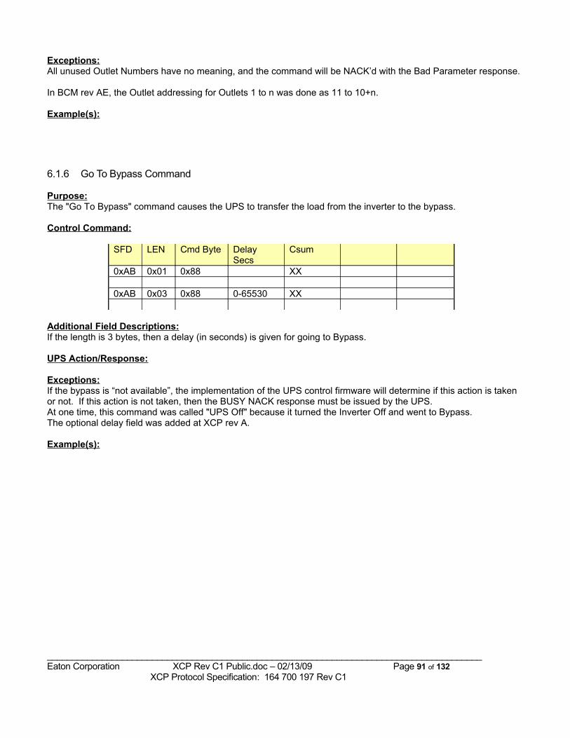
Exceptions:All unused Outlet Numbers have no meaning, and the command will be NACK’d with the Bad Parameter response.
In BCM rev AE, the Outlet addressing for Outlets 1 to n was done as 11 to 10+n.
Example(s):
6.1.6 Go To Bypass Command
Purpose:The "Go To Bypass" command causes the UPS to transfer the load from the inverter to the bypass.
Control Command:
SFD LEN Cmd Byte Delay Secs
Csum
0xAB 0x01 0x88 XX
0xAB 0x03 0x88 0-65530 XX
Additional Field Descriptions:If the length is 3 bytes, then a delay (in seconds) is given for going to Bypass.
UPS Action/Response:
Exceptions:If the bypass is “not available”, the implementation of the UPS control firmware will determine if this action is taken or not. If this action is not taken, then the BUSY NACK response must be issued by the UPS.At one time, this command was called "UPS Off" because it turned the Inverter Off and went to Bypass.The optional delay field was added at XCP rev A.
Example(s):
_______________________________________________________________________________________Eaton Corporation XCP Rev C1 Public.doc – 02/13/09 Page 91 of 132 XCP Protocol Specification: 164 700 197 Rev C1
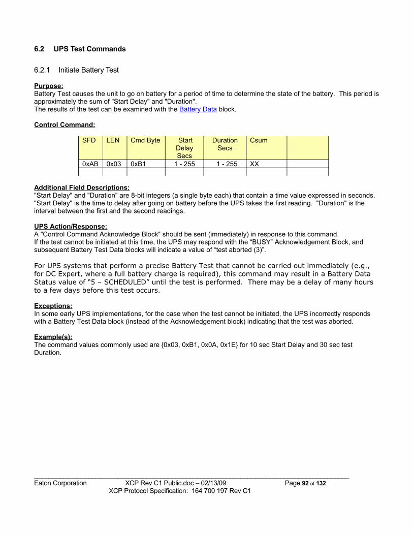
6.2 UPS Test Commands
6.2.1 Initiate Battery Test
Purpose:Battery Test causes the unit to go on battery for a period of time to determine the state of the battery. This period is approximately the sum of "Start Delay" and "Duration".The results of the test can be examined with the Battery Data block.
Control Command:
SFD LEN Cmd Byte StartDelay Secs
Duration Secs
Csum
0xAB 0x03 0xB1 1 - 255 1 - 255 XX
Additional Field Descriptions:"Start Delay" and "Duration" are 8-bit integers (a single byte each) that contain a time value expressed in seconds. "Start Delay" is the time to delay after going on battery before the UPS takes the first reading. "Duration" is the interval between the first and the second readings.
UPS Action/Response:A "Control Command Acknowledge Block" should be sent (immediately) in response to this command. If the test cannot be initiated at this time, the UPS may respond with the “BUSY” Acknowledgement Block, and subsequent Battery Test Data blocks will indicate a value of “test aborted (3)”.
For UPS systems that perform a precise Battery Test that cannot be carried out immediately (e.g., for DC Expert, where a full battery charge is required), this command may result in a Battery Data Status value of “5 – SCHEDULED” until the test is performed. There may be a delay of many hours to a few days before this test occurs.
Exceptions:In some early UPS implementations, for the case when the test cannot be initiated, the UPS incorrectly responds with a Battery Test Data block (instead of the Acknowledgement block) indicating that the test was aborted.
Example(s):The command values commonly used are {0x03, 0xB1, 0x0A, 0x1E} for 10 sec Start Delay and 30 sec test Duration.
_______________________________________________________________________________________Eaton Corporation XCP Rev C1 Public.doc – 02/13/09 Page 92 of 132 XCP Protocol Specification: 164 700 197 Rev C1
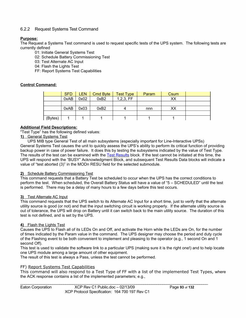
6.2.2 Request Systems Test Command
Purpose:The Request a Systems Test command is used to request specific tests of the UPS system. The following tests are currently defined
01: Initiate General Systems Test02: Schedule Battery Commissioning Test03: Test Alternate AC Input04: Flash the Lights TestFF: Report Systems Test Capabilities
Control Command:
SFD LEN Cmd Byte Test Type Param Csum0xAB 0x02 0xB2 1,2,3, FF XX
0xAB 0x03 0xB2 4 nnn XX
(Bytes) 1 1 1 1 1 1
Additional Field Descriptions:"Test Type” has the following defined values:1) General Systems Test
UPS MIB type General Test of all main subsystems (especially important for Line-Interactive UPSs)General Systems Test causes the unit to quickly assess the UPS’s ability to perform its critical function of providing backup power in case of power failure. It does this by testing the subsystems indicated by the value of Test Type.The results of the test can be examined with the Test Results block. If the test cannot be initiated at this time, the UPS will respond with the “BUSY” Acknowledgment Block, and subsequent Test Results Data blocks will indicate a value of “test aborted (3)” in the MODn RESU field for the selected submodule.
2) Schedule Battery Commissioning Test This command requests that a Battery Test be scheduled to occur when the UPS has the correct conditions to perform the test. When scheduled, the Overall Battery Status will have a value of “5 – SCHEDULED” until the test is performed. There may be a delay of many hours to a few days before this test occurs.
3) Test Alternate AC Input This command requests that the UPS switch to its Alternate AC Input for a short time, just to verify that the alternate utility source is good (or not) and that the input switching circuit is working properly. If the alternate utility source is out of tolerance, the UPS will drop on Battery until it can switch back to the main utility source. The duration of this test is not defined, and is set by the UPS.
4) Flash the Lights Test Causes the UPS to Flash all of its LEDs On and Off, and activate the Horn while the LEDs are On, for the number of times indicated by the Param value in the command. The UPS designer may choose the period and duty cycle of the Flashing event to be both convenient to implement and pleasing to the operator (e.g., 1 second On and 1 second Off).This test is used to validate the software link to a particular UPS (making sure it is the right one!) and to help locate one UPS module among a large amount of other equipment.The result of this test is always a Pass, unless the test cannot be performed.
FF) Report Systems Test CapabilitiesThis command will also respond to a Test Type of FF with a list of the implemented Test Types, where the ACK response contains a list of the implemented parameters; e.g.,_______________________________________________________________________________________Eaton Corporation XCP Rev C1 Public.doc – 02/13/09 Page 93 of 132 XCP Protocol Specification: 164 700 197 Rev C1
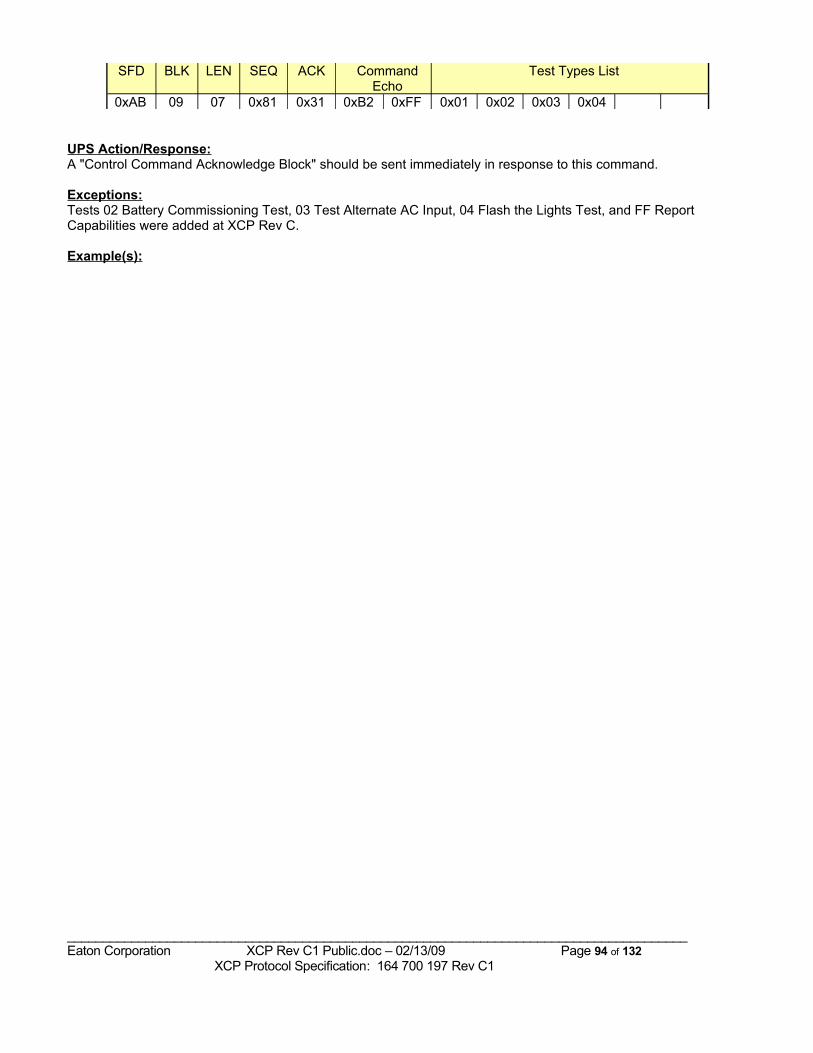
SFD BLK LEN SEQ ACK Command Echo
Test Types List
0xAB 09 07 0x81 0x31 0xB2 0xFF 0x01 0x02 0x03 0x04
UPS Action/Response:A "Control Command Acknowledge Block" should be sent immediately in response to this command.
Exceptions:Tests 02 Battery Commissioning Test, 03 Test Alternate AC Input, 04 Flash the Lights Test, and FF Report Capabilities were added at XCP Rev C.
Example(s):
_______________________________________________________________________________________Eaton Corporation XCP Rev C1 Public.doc – 02/13/09 Page 94 of 132 XCP Protocol Specification: 164 700 197 Rev C1
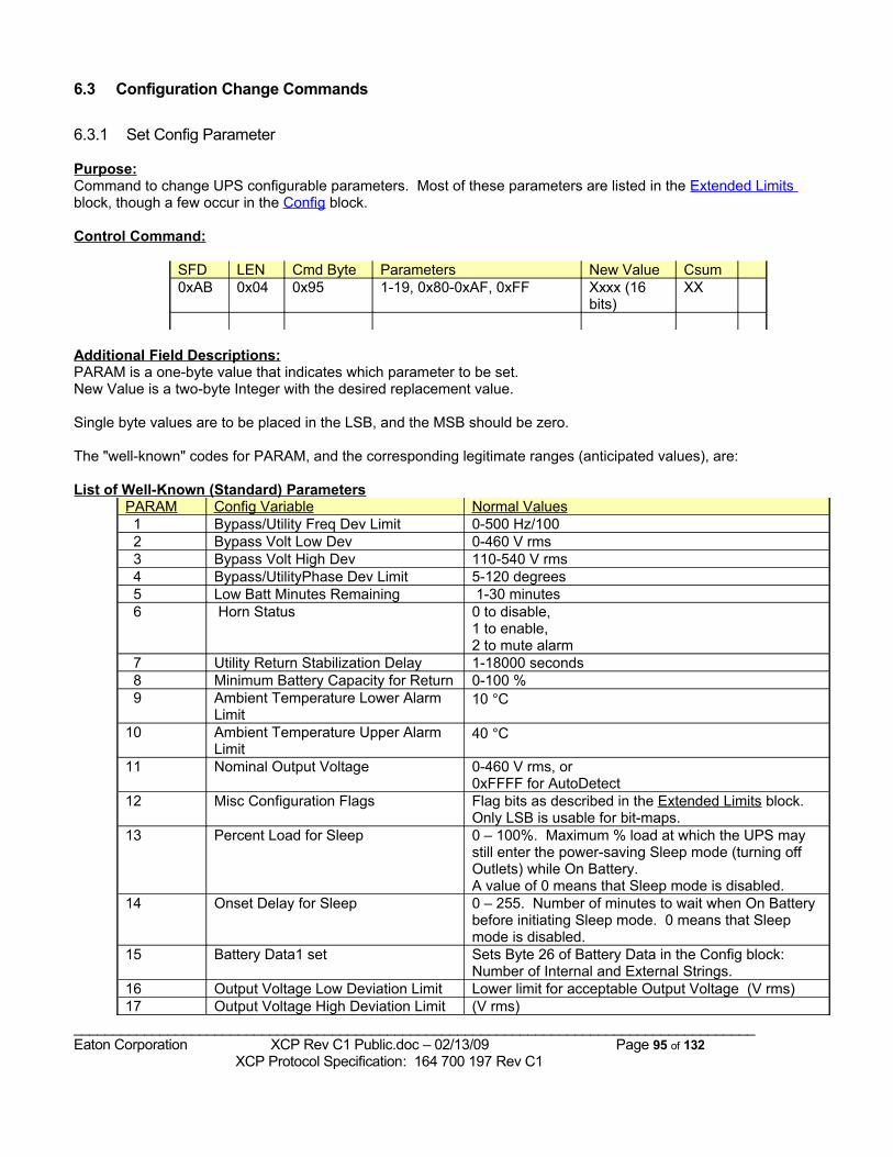
6.3 Configuration Change Commands
6.3.1 Set Config Parameter
Purpose:Command to change UPS configurable parameters. Most of these parameters are listed in the Extended Limits block, though a few occur in the Config block.
Control Command:
SFD LEN Cmd Byte Parameters New Value Csum0xAB 0x04 0x95 1-19, 0x80-0xAF, 0xFF Xxxx (16
bits)XX
Additional Field Descriptions:PARAM is a one-byte value that indicates which parameter to be set.New Value is a two-byte Integer with the desired replacement value.
Single byte values are to be placed in the LSB, and the MSB should be zero.
The "well-known" codes for PARAM, and the corresponding legitimate ranges (anticipated values), are:
List of Well-Known (Standard) ParametersPARAM Config Variable Normal Values 1 Bypass/Utility Freq Dev Limit 0-500 Hz/100 2 Bypass Volt Low Dev 0-460 V rms 3 Bypass Volt High Dev 110-540 V rms 4 Bypass/UtilityPhase Dev Limit 5-120 degrees 5 Low Batt Minutes Remaining 1-30 minutes 6 Horn Status 0 to disable,
1 to enable, 2 to mute alarm
7 Utility Return Stabilization Delay 1-18000 seconds 8 Minimum Battery Capacity for Return 0-100 % 9 Ambient Temperature Lower Alarm
Limit10 °C
10 Ambient Temperature Upper Alarm Limit
40 °C
11 Nominal Output Voltage 0-460 V rms, or0xFFFF for AutoDetect
12 Misc Configuration Flags Flag bits as described in the Extended Limits block. Only LSB is usable for bit-maps.
13 Percent Load for Sleep 0 – 100%. Maximum % load at which the UPS may still enter the power-saving Sleep mode (turning off Outlets) while On Battery. A value of 0 means that Sleep mode is disabled.
14 Onset Delay for Sleep 0 – 255. Number of minutes to wait when On Battery before initiating Sleep mode. 0 means that Sleep mode is disabled.
15 Battery Data1 set Sets Byte 26 of Battery Data in the Config block: Number of Internal and External Strings.
16 Output Voltage Low Deviation Limit Lower limit for acceptable Output Voltage (V rms)17 Output Voltage High Deviation Limit (V rms)
_______________________________________________________________________________________Eaton Corporation XCP Rev C1 Public.doc – 02/13/09 Page 95 of 132 XCP Protocol Specification: 164 700 197 Rev C1
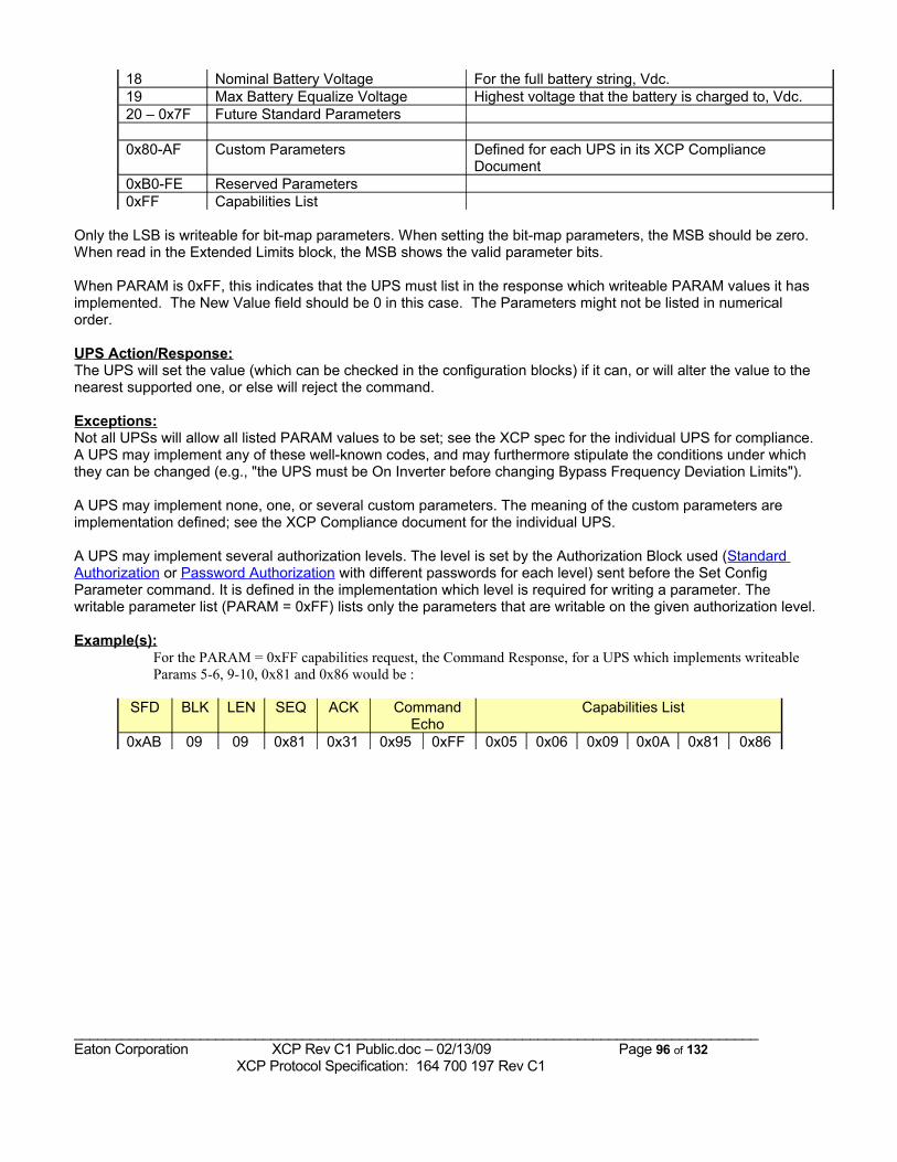
18 Nominal Battery Voltage For the full battery string, Vdc.19 Max Battery Equalize Voltage Highest voltage that the battery is charged to, Vdc.20 – 0x7F Future Standard Parameters
0x80-AF Custom Parameters Defined for each UPS in its XCP Compliance Document
0xB0-FE Reserved Parameters0xFF Capabilities List
Only the LSB is writeable for bit-map parameters. When setting the bit-map parameters, the MSB should be zero. When read in the Extended Limits block, the MSB shows the valid parameter bits.
When PARAM is 0xFF, this indicates that the UPS must list in the response which writeable PARAM values it has implemented. The New Value field should be 0 in this case. The Parameters might not be listed in numerical order.
UPS Action/Response:The UPS will set the value (which can be checked in the configuration blocks) if it can, or will alter the value to the nearest supported one, or else will reject the command.
Exceptions:Not all UPSs will allow all listed PARAM values to be set; see the XCP spec for the individual UPS for compliance.A UPS may implement any of these well-known codes, and may furthermore stipulate the conditions under which they can be changed (e.g., "the UPS must be On Inverter before changing Bypass Frequency Deviation Limits").
A UPS may implement none, one, or several custom parameters. The meaning of the custom parameters are implementation defined; see the XCP Compliance document for the individual UPS.
A UPS may implement several authorization levels. The level is set by the Authorization Block used (Standard Authorization or Password Authorization with different passwords for each level) sent before the Set Config Parameter command. It is defined in the implementation which level is required for writing a parameter. The writable parameter list (PARAM = 0xFF) lists only the parameters that are writable on the given authorization level.
Example(s):For the PARAM = 0xFF capabilities request, the Command Response, for a UPS which implements writeable Params 5-6, 9-10, 0x81 and 0x86 would be :
SFD BLK LEN SEQ ACK Command Echo
Capabilities List
0xAB 09 09 0x81 0x31 0x95 0xFF 0x05 0x06 0x09 0x0A 0x81 0x86
_______________________________________________________________________________________Eaton Corporation XCP Rev C1 Public.doc – 02/13/09 Page 96 of 132 XCP Protocol Specification: 164 700 197 Rev C1
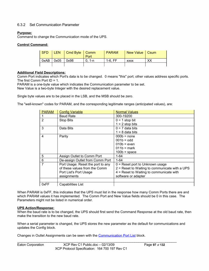
6.3.2 Set Communication Parameter
Purpose:Command to change the Communication mode of the UPS.
Control Command:
SFD LEN Cmd Byte Comm Port
PARAM New Value Csum
0xAB 0x05 0x98 0, 1-n 1-6, FF xxxx XX
Additional Field Descriptions:Comm Port indicates which Port's data is to be changed. 0 means "this" port; other values address specific ports. The first Comm Port ID = 1.PARAM is a one-byte value which indicates the Communication parameter to be set.New Value is a two-byte Integer with the desired replacement value.
Single byte values are to be placed in the LSB, and the MSB should be zero.
The "well-known" codes for PARAM, and the corresponding legitimate ranges (anticipated values), are:
PARAM Config Variable Normal Values1 Baud Rate 300-192002 Stop Bits 0 = 1 stop bit
1 = 2 stop bits3 Data Bits 0 = 7 data bits
1 = 8 data bits4 Parity 000b = none
001b = odd010b = even011b = mark 100b = space
5 Assign Outlet to Comm Port 1-646 De-assign Outlet from Comm Port 1-647 Port Usage: Reset the port to any
of these values from the Comm Port List's Port Usage assignments
0 = Reset port to Unknown usage2 = Reset to Waiting to communicate with a UPS4 = Reset to Waiting to communicate with software or adapter
0xFF Capabilities List
When PARAM is 0xFF, this indicates that the UPS must list in the response how many Comm Ports there are and which PARAM values it has implemented. The Comm Port and New Value fields should be 0 in this case. The Parameters might not be listed in numerical order.
UPS Action/Response:When the baud rate is to be changed, the UPS should first send the Command Response at the old baud rate, then make the transition to the new baud rate.
When a serial parameter is changed, the UPS stores the new parameter as the default for communications and updates the Config block.
Changes in Outlet Assignments can be seen with the Communication Port List block._______________________________________________________________________________________Eaton Corporation XCP Rev C1 Public.doc – 02/13/09 Page 97 of 132 XCP Protocol Specification: 164 700 197 Rev C1
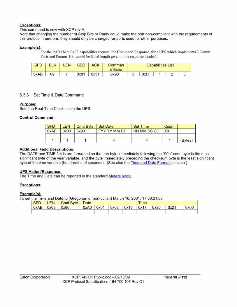
Exceptions:This command is new with XCP rev A.Note that changing the number of Stop Bits or Parity could make the port non-compliant with the requirements of this protocol; therefore, they should only be changed for ports used for other purposes.
Example(s):For the PARAM = 0xFF capabilities request, the Command Response, for a UPS which implements 3 Comm Ports and Params 1-3, would be (final length given in the response header):
SFD BLK LEN SEQ ACK Command Echo
Capabilities List
0xAB 09 7 0x81 0x31 0x98 3 0xFF 1 2 3
6.3.3 Set Time & Date Command
Purpose:Sets the Real-Time Clock inside the UPS.
Control Command:
SFD LEN Cmd Byte Set Date Set Time Csum0xAB 0x09 0x90 FYY YY MM DD HH MM SS CC XX
1 1 1 4 4 1 (Bytes)
Additional Field Descriptions:The DATE and TIME fields are formatted so that the byte immediately following the "90h" code byte is the most significant byte of the year variable, and the byte immediately preceding the checksum byte is the least significant byte of the time variable (hundredths of seconds). (See also the Time and Date Formats section.)
UPS Action/Response:The Time and Date can be reported in the standard Meters block.
Exceptions:
Example(s):To set the Time and Date to (Gregorian or non-Julian) March 16, 2001, 17:30:21:00
SFD LEN Cmd Byte Date Time0xAB 0x09 0x90 0xA0 0x01 0x03 0x16 0x17 0x30 0x21 0x00
_______________________________________________________________________________________Eaton Corporation XCP Rev C1 Public.doc – 02/13/09 Page 98 of 132 XCP Protocol Specification: 164 700 197 Rev C1
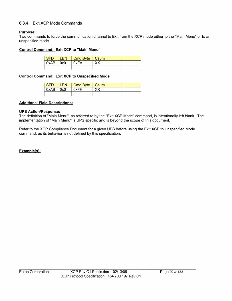
6.3.4 Exit XCP Mode Commands
Purpose:Two commands to force the communication channel to Exit from the XCP mode either to the "Main Menu" or to an unspecified mode.
Control Command: Exit XCP to "Main Menu"
SFD LEN Cmd Byte Csum0xAB 0x01 0xFA XX
Control Command: Exit XCP to Unspecified Mode
SFD LEN Cmd Byte Csum0xAB 0x01 0xFF XX
Additional Field Descriptions:
UPS Action/Response:The definition of "Main Menu", as referred to by the "Exit XCP Mode" command, is intentionally left blank. The implementation of "Main Menu" is UPS specific and is beyond the scope of this document.
Refer to the XCP Compliance Document for a given UPS before using the Exit XCP to Unspecified Mode command, as its behavior is not defined by this specification.
Example(s):
_______________________________________________________________________________________Eaton Corporation XCP Rev C1 Public.doc – 02/13/09 Page 99 of 132 XCP Protocol Specification: 164 700 197 Rev C1
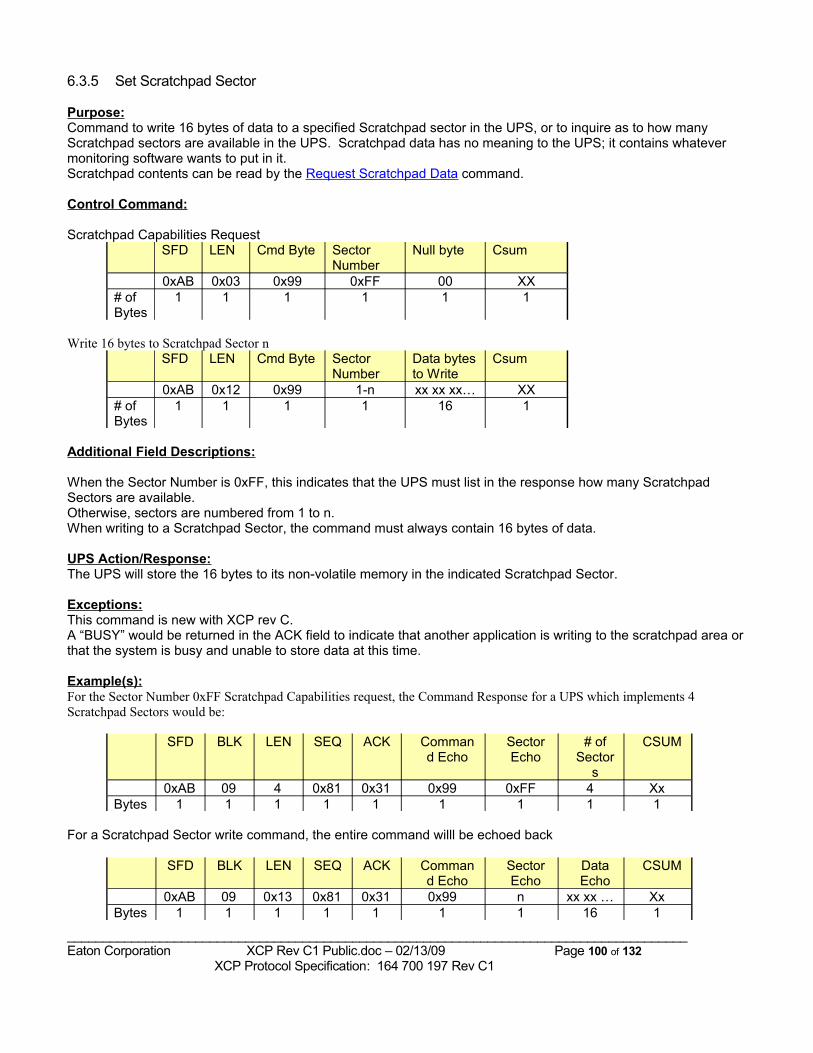
6.3.5 Set Scratchpad Sector
Purpose:Command to write 16 bytes of data to a specified Scratchpad sector in the UPS, or to inquire as to how many Scratchpad sectors are available in the UPS. Scratchpad data has no meaning to the UPS; it contains whatever monitoring software wants to put in it.Scratchpad contents can be read by the Request Scratchpad Data command.
Control Command:
Scratchpad Capabilities RequestSFD LEN Cmd Byte Sector
NumberNull byte Csum
0xAB 0x03 0x99 0xFF 00 XX# of Bytes
1 1 1 1 1 1
Write 16 bytes to Scratchpad Sector nSFD LEN Cmd Byte Sector
NumberData bytes to Write
Csum
0xAB 0x12 0x99 1-n xx xx xx… XX# of Bytes
1 1 1 1 16 1
Additional Field Descriptions:
When the Sector Number is 0xFF, this indicates that the UPS must list in the response how many Scratchpad Sectors are available. Otherwise, sectors are numbered from 1 to n.When writing to a Scratchpad Sector, the command must always contain 16 bytes of data.
UPS Action/Response:The UPS will store the 16 bytes to its non-volatile memory in the indicated Scratchpad Sector.
Exceptions:This command is new with XCP rev C.A “BUSY” would be returned in the ACK field to indicate that another application is writing to the scratchpad area or that the system is busy and unable to store data at this time.
Example(s):For the Sector Number 0xFF Scratchpad Capabilities request, the Command Response for a UPS which implements 4 Scratchpad Sectors would be:
SFD BLK LEN SEQ ACK Command Echo
Sector Echo
# of Sector
s
CSUM
0xAB 09 4 0x81 0x31 0x99 0xFF 4 XxBytes 1 1 1 1 1 1 1 1 1
For a Scratchpad Sector write command, the entire command willl be echoed back
SFD BLK LEN SEQ ACK Command Echo
Sector Echo
Data Echo
CSUM
0xAB 09 0x13 0x81 0x31 0x99 n xx xx … XxBytes 1 1 1 1 1 1 1 16 1
_______________________________________________________________________________________Eaton Corporation XCP Rev C1 Public.doc – 02/13/09 Page 100 of 132 XCP Protocol Specification: 164 700 197 Rev C1
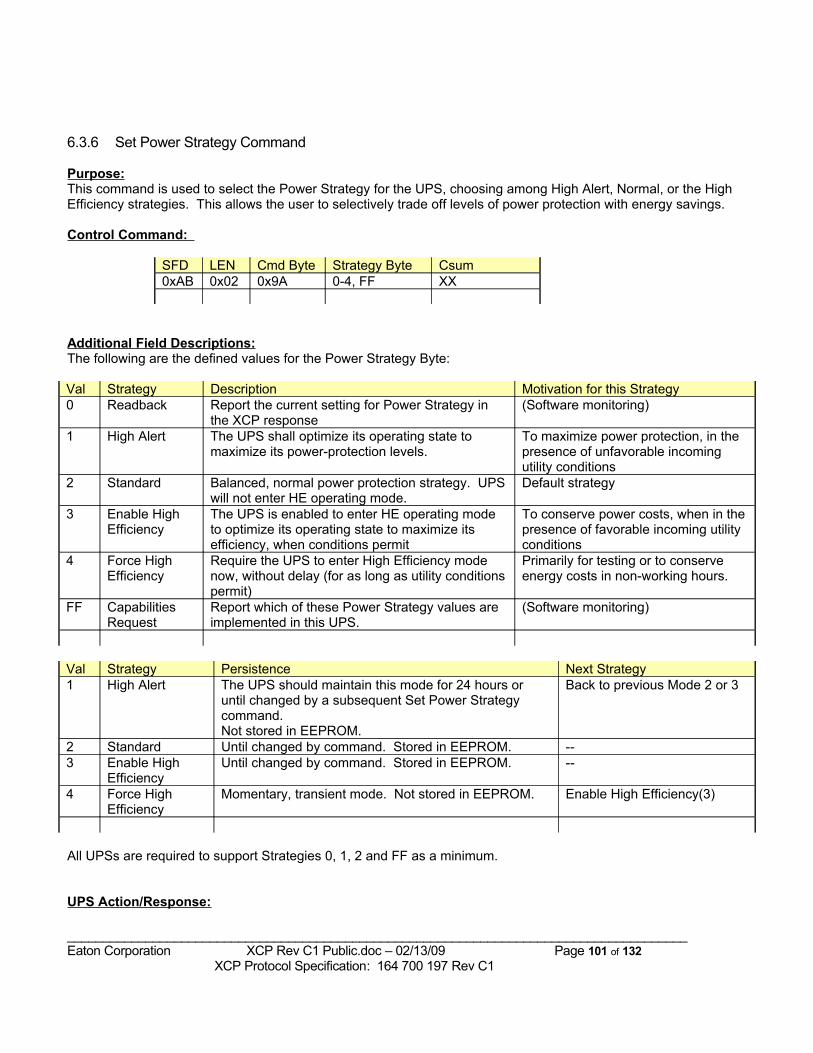
6.3.6 Set Power Strategy Command
Purpose:This command is used to select the Power Strategy for the UPS, choosing among High Alert, Normal, or the High Efficiency strategies. This allows the user to selectively trade off levels of power protection with energy savings.
Control Command:
SFD LEN Cmd Byte Strategy Byte Csum0xAB 0x02 0x9A 0-4, FF XX
Additional Field Descriptions:The following are the defined values for the Power Strategy Byte:
Val Strategy Description Motivation for this Strategy0 Readback Report the current setting for Power Strategy in
the XCP response(Software monitoring)
1 High Alert The UPS shall optimize its operating state to maximize its power-protection levels.
To maximize power protection, in the presence of unfavorable incoming utility conditions
2 Standard Balanced, normal power protection strategy. UPS will not enter HE operating mode.
Default strategy
3 Enable High Efficiency
The UPS is enabled to enter HE operating mode to optimize its operating state to maximize its efficiency, when conditions permit
To conserve power costs, when in the presence of favorable incoming utility conditions
4 Force High Efficiency
Require the UPS to enter High Efficiency mode now, without delay (for as long as utility conditions permit)
Primarily for testing or to conserve energy costs in non-working hours.
FF Capabilities Request
Report which of these Power Strategy values are implemented in this UPS.
(Software monitoring)
Val Strategy Persistence Next Strategy1 High Alert The UPS should maintain this mode for 24 hours or
until changed by a subsequent Set Power Strategy command. Not stored in EEPROM.
Back to previous Mode 2 or 3
2 Standard Until changed by command. Stored in EEPROM. --3 Enable High
EfficiencyUntil changed by command. Stored in EEPROM. --
4 Force High Efficiency
Momentary, transient mode. Not stored in EEPROM. Enable High Efficiency(3)
All UPSs are required to support Strategies 0, 1, 2 and FF as a minimum.
UPS Action/Response:
_______________________________________________________________________________________Eaton Corporation XCP Rev C1 Public.doc – 02/13/09 Page 101 of 132 XCP Protocol Specification: 164 700 197 Rev C1
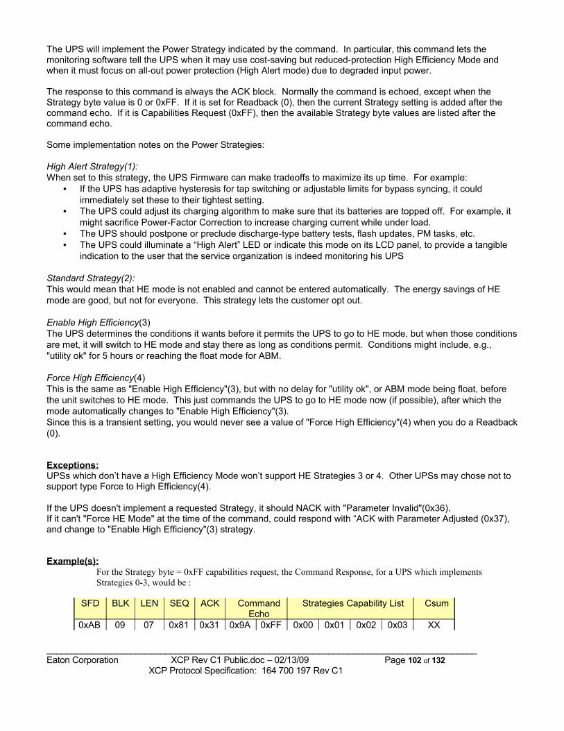
The UPS will implement the Power Strategy indicated by the command. In particular, this command lets the monitoring software tell the UPS when it may use cost-saving but reduced-protection High Efficiency Mode and when it must focus on all-out power protection (High Alert mode) due to degraded input power.
The response to this command is always the ACK block. Normally the command is echoed, except when the Strategy byte value is 0 or 0xFF. If it is set for Readback (0), then the current Strategy setting is added after the command echo. If it is Capabilities Request (0xFF), then the available Strategy byte values are listed after the command echo.
Some implementation notes on the Power Strategies:
High Alert Strategy(1):When set to this strategy, the UPS Firmware can make tradeoffs to maximize its up time. For example:
• If the UPS has adaptive hysteresis for tap switching or adjustable limits for bypass syncing, it could immediately set these to their tightest setting.
• The UPS could adjust its charging algorithm to make sure that its batteries are topped off. For example, it might sacrifice Power-Factor Correction to increase charging current while under load.
• The UPS should postpone or preclude discharge-type battery tests, flash updates, PM tasks, etc.• The UPS could illuminate a “High Alert” LED or indicate this mode on its LCD panel, to provide a tangible
indication to the user that the service organization is indeed monitoring his UPS
Standard Strategy(2):This would mean that HE mode is not enabled and cannot be entered automatically. The energy savings of HE mode are good, but not for everyone. This strategy lets the customer opt out.
Enable High Efficiency(3) The UPS determines the conditions it wants before it permits the UPS to go to HE mode, but when those conditions are met, it will switch to HE mode and stay there as long as conditions permit. Conditions might include, e.g., "utility ok" for 5 hours or reaching the float mode for ABM.
Force High Efficiency(4) This is the same as "Enable High Efficiency"(3), but with no delay for "utility ok", or ABM mode being float, before the unit switches to HE mode. This just commands the UPS to go to HE mode now (if possible), after which the mode automatically changes to "Enable High Efficiency"(3).Since this is a transient setting, you would never see a value of "Force High Efficiency"(4) when you do a Readback (0).
Exceptions:UPSs which don’t have a High Efficiency Mode won’t support HE Strategies 3 or 4. Other UPSs may chose not to support type Force to High Efficiency(4).
If the UPS doesn't implement a requested Strategy, it should NACK with "Parameter Invalid"(0x36).If it can't "Force HE Mode" at the time of the command, could respond with “ACK with Parameter Adjusted (0x37), and change to "Enable High Efficiency"(3) strategy.
Example(s):For the Strategy byte = 0xFF capabilities request, the Command Response, for a UPS which implements Strategies 0-3, would be :
SFD BLK LEN SEQ ACK Command Echo
Strategies Capability List Csum
0xAB 09 07 0x81 0x31 0x9A 0xFF 0x00 0x01 0x02 0x03 XX
_______________________________________________________________________________________Eaton Corporation XCP Rev C1 Public.doc – 02/13/09 Page 102 of 132 XCP Protocol Specification: 164 700 197 Rev C1
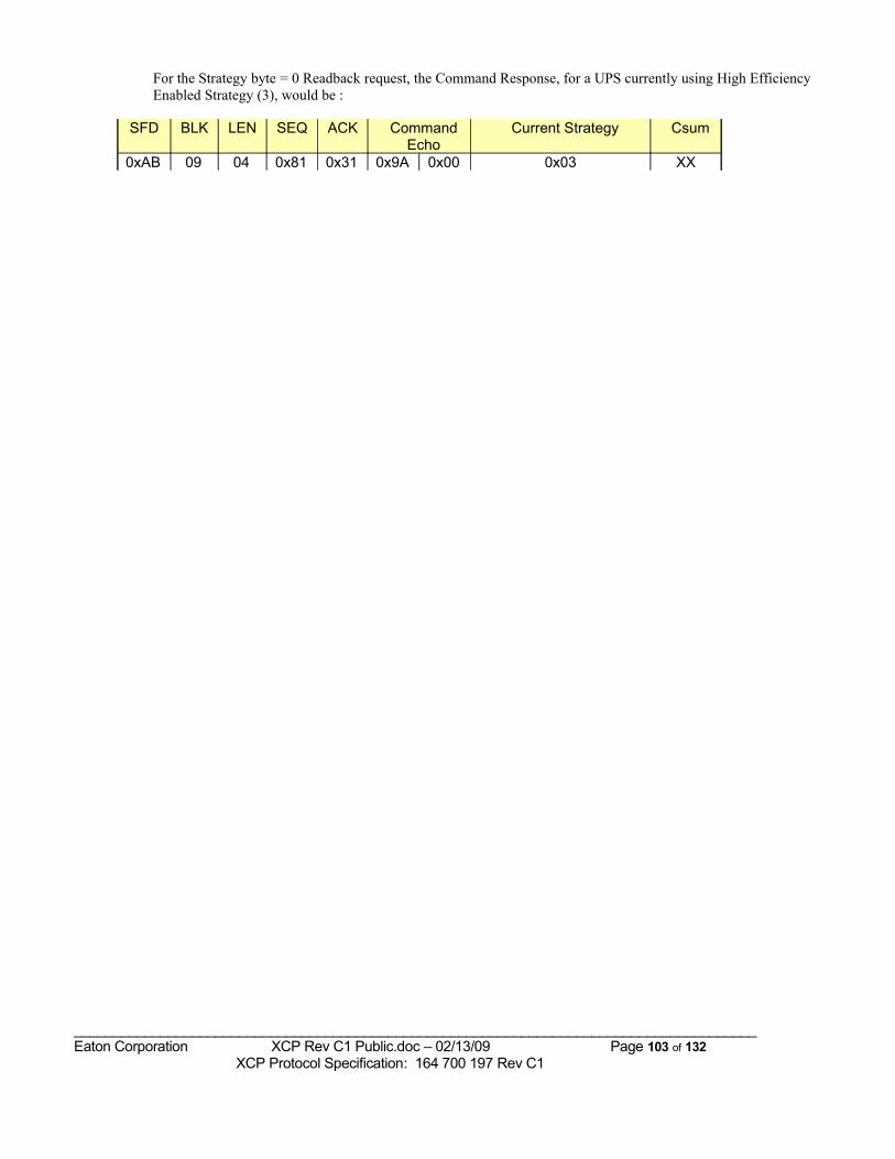
For the Strategy byte = 0 Readback request, the Command Response, for a UPS currently using High Efficiency Enabled Strategy (3), would be :
SFD BLK LEN SEQ ACK Command Echo
Current Strategy Csum
0xAB 09 04 0x81 0x31 0x9A 0x00 0x03 XX
_______________________________________________________________________________________Eaton Corporation XCP Rev C1 Public.doc – 02/13/09 Page 103 of 132 XCP Protocol Specification: 164 700 197 Rev C1
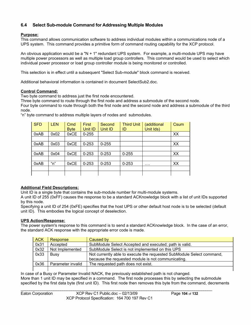
6.4 Select Sub-module Command for Addressing Multiple Modules
Purpose:This command allows communication software to address individual modules within a communications node of a UPS system. This command provides a primitive form of command routing capability for the XCP protocol.
An obvious application would be a "N + 1" redundant UPS system. For example, a multi-module UPS may have multiple power processors as well as multiple load group controllers. This command would be used to select which individual power processor or load group controller module is being monitored or controlled.
This selection is in effect until a subsequent "Select Sub-module" block command is received.
Additional behavioral information is contained in document SelectSub2.doc.
Control Command:Two byte command to address just the first node encountered.Three byte command to route through the first node and address a submodule of the second node.Four byte command to route through both the first node and the second node and address a submodule of the third node.“n” byte command to address multiple layers of nodes and submodules.
SFD LEN Cmd Byte
First Unit ID
Second Unit ID
Third Unit ID
(additional Unit Ids)
Csum
0xAB 0x02 0xCE 0-255 XX
0xAB 0x03 0xCE 0-253 0-255 XX
0xAB 0x04 0xCE 0-253 0-253 0-255 XX
0xAB “n” 0xCE 0-253 0-253 0-253 …. XX
Additional Field Descriptions:Unit ID is a single byte that contains the sub-module number for multi-module systems.A unit ID of 255 (0xFF) causes the response to be a standard ACKnowledge block with a list of unit IDs supported by this node.Specifying a unit ID of 254 (0xFE) specifies that the host UPS or other default host node is to be selected (default unit ID). This embodies the logical concept of deselection.
UPS Action/Response:The power system's response to this command is to send a standard ACKnowledge block. In the case of an error, the standard ACK response with the appropriate error code is made.
ACK Response Caused by0x31 Accepted SubModule Select Accepted and executed; path is valid. 0x32 Not Implemented SubModule Select is not implemented on this UPS0x33 Busy Not currently able to execute the requested SubModule Select command,
because the requested module is not communicating.0x36 Parameter invalid The requested path does not exist.
In case of a Busy or Parameter Invalid NACK, the previously established path is not changed.More than 1 unit ID may be specified in a command. The first node processes this by selecting the submodule specified by the first data byte (first unit ID). This first node then removes this byte from the command, decrements _______________________________________________________________________________________Eaton Corporation XCP Rev C1 Public.doc – 02/13/09 Page 104 of 132 XCP Protocol Specification: 164 700 197 Rev C1
the length (LEN) field, calculates the resulting checksum and passes this modified command on to the newly selected node. This newly selected node then processes the command that it receives in the same manner.
Exceptions:For the purpose of backwards compatibility, and only in the case where NetXCP is being used and the single submodule selected is number 1, the power system's response to this command is to send a standard Status block that contains the number of the module that was just selected.
Example(s):If unit ID 255 is selected, then the response is a special ACKnowledge block. If the receiving node has four submodules that can be selected, then the sequence would appear as follows:
Command sent to node:0xAB 0x02 0xCE 0xFF CC
Response sent back from node:0xAB 0x09 0x07 0x81 0x31 0xCE 0xFF 0x01 0x02 0x03 0x04 CC
Where CC is the checksum byte.
By convention, the first SubMod ID listed in the response is the default SubMod ID (01 in this example).
_______________________________________________________________________________________Eaton Corporation XCP Rev C1 Public.doc – 02/13/09 Page 105 of 132 XCP Protocol Specification: 164 700 197 Rev C1
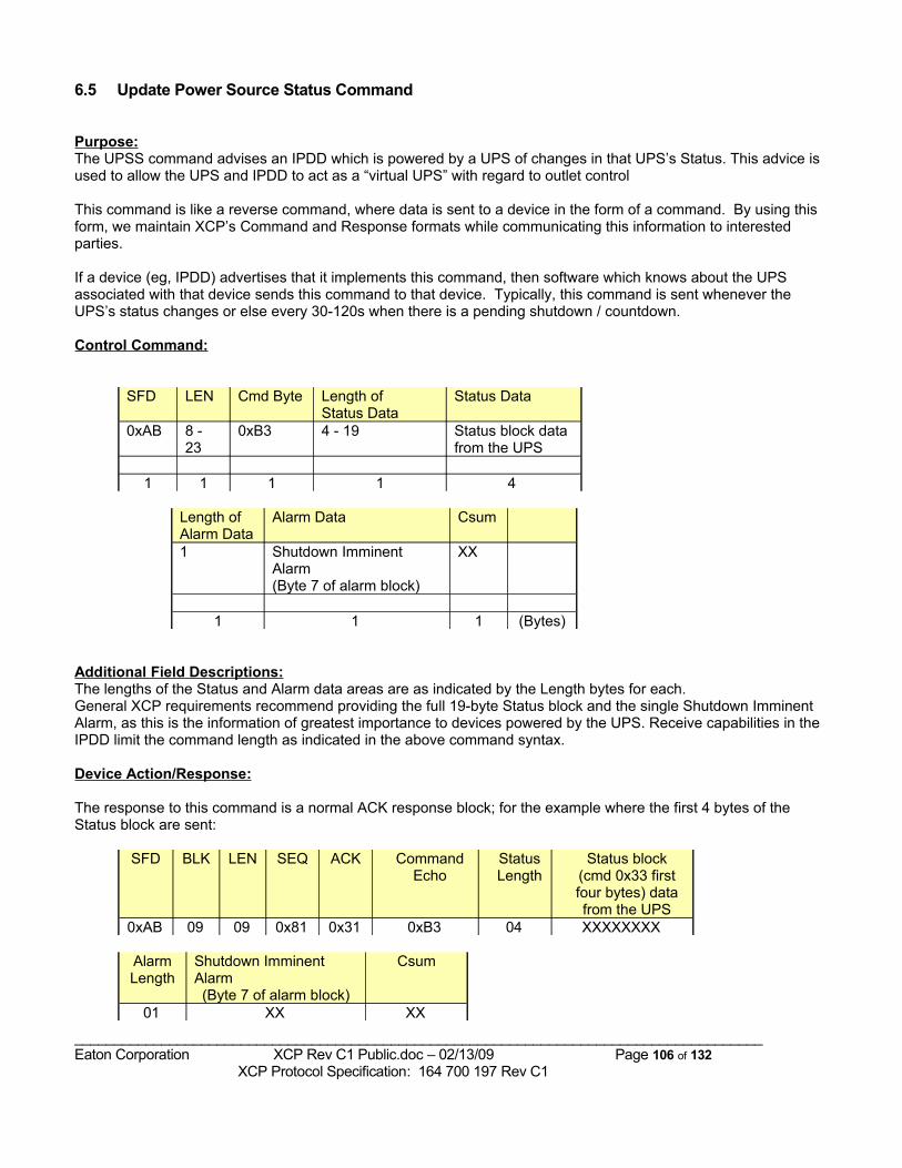
6.5 Update Power Source Status Command
Purpose:The UPSS command advises an IPDD which is powered by a UPS of changes in that UPS’s Status. This advice is used to allow the UPS and IPDD to act as a “virtual UPS” with regard to outlet control
This command is like a reverse command, where data is sent to a device in the form of a command. By using this form, we maintain XCP’s Command and Response formats while communicating this information to interested parties.
If a device (eg, IPDD) advertises that it implements this command, then software which knows about the UPS associated with that device sends this command to that device. Typically, this command is sent whenever the UPS’s status changes or else every 30-120s when there is a pending shutdown / countdown.
Control Command:
SFD LEN Cmd Byte Length of Status Data
Status Data
0xAB 8 - 23
0xB3 4 - 19 Status block data from the UPS
1 1 1 1 4
Length of Alarm Data
Alarm Data Csum
1 Shutdown Imminent Alarm(Byte 7 of alarm block)
XX
1 1 1 (Bytes)
Additional Field Descriptions:The lengths of the Status and Alarm data areas are as indicated by the Length bytes for each.General XCP requirements recommend providing the full 19-byte Status block and the single Shutdown Imminent Alarm, as this is the information of greatest importance to devices powered by the UPS. Receive capabilities in the IPDD limit the command length as indicated in the above command syntax.
Device Action/Response:
The response to this command is a normal ACK response block; for the example where the first 4 bytes of the Status block are sent:
SFD BLK LEN SEQ ACK Command Echo
Status Length
Status block (cmd 0x33 first four bytes) data from the UPS
0xAB 09 09 0x81 0x31 0xB3 04 XXXXXXXX
Alarm Length
Shutdown Imminent Alarm(Byte 7 of alarm block)
Csum
01 XX XX
_______________________________________________________________________________________Eaton Corporation XCP Rev C1 Public.doc – 02/13/09 Page 106 of 132 XCP Protocol Specification: 164 700 197 Rev C1
Any 0xB3 command that exceeds the “Maximum Supported Command Length” will be ignored
When the 0xB3 command is received and the “Topology” Status byte 2 bit 7 byte has changed from 1 to 0 (state change indicating the Power Source has just gone to battery), an OnBattery state is recorded in the IPDD. When bit 7 changes from 0 to 1, a normal state is recorded in the IPDD.
Exceptions:The length of this command cannot exceed the size of the device’s input buffer, as reported in the ID Block’s “Maximum Supported Command Length”. If necessary, the length of the Status data area can be reduced to fit.
Example(s):
_______________________________________________________________________________________Eaton Corporation XCP Rev C1 Public.doc – 02/13/09 Page 107 of 132 XCP Protocol Specification: 164 700 197 Rev C1
7 Implementation Details7.1 Mandatory requirements for UPS implementersTo ensure Communication Software a consistent base of responses from all Powerware UPSs, the following requirements must be met by All new UPSs:1. Must meet the Timing Requirements for Commands and Responses2. Must provide error-free responses that conform to this specification, with proper checksums3. Must NACK unimplemented commands or invalid parameters4. Must respond to the PnP event and enter XCP mode immediately for Discovery5. Must require proper Authorization of Control Commands6. Must respond to the Set Requested-only Mode commandwith a Standard ID Block.
A Standard UPS must implement the following additional blocks and commands:• ID Block• Status Block • Meter Block • Active Alarms Block • Configuration Block • Extended Limits Block • Command List Block • Outlet Monitoring Block (if there are switchable Outlets)• Communication Capabilities Block• Set Comm Parameter command (if more than 1200 baud supported)
and must implement the following commands to reach full UPS MIB compliance:• UPS On Command • Delayed Load Power Off & Restart • UPS Off /Load Power Off • Scheduled UPS On in "n" Minutes or Scheduled UPS On at Date & Time• Scheduled Load Power Off in "n" Minutes or Scheduled Load Power Off at Date & Time• Set Config Parameter for Low Battery Warning and Horn Mute• Initiate Battery Test • Request a Systems Test
and for full support of our Power Management software strategies, the UPS must implement the following commands:• UPS Topology Data Block • Request Scratchpad Data • Set Outlet Parameter (if there are switchable Outlets)• Set Scratchpad Sector • Set Power Strategy
Process for deviating from these requirements:If the developers of the UPS must choose not to meet these requirements (e.g., due to limited resources), then this deviation should be declared in the Product’s PDR and XCP Compliance documents, so that management and marketing are formally and knowingly agreeing to such deviations early in the project.
_______________________________________________________________________________________Eaton Corporation XCP Rev C1 Public.doc – 02/13/09 Page 108 of 132 XCP Protocol Specification: 164 700 197 Rev C1
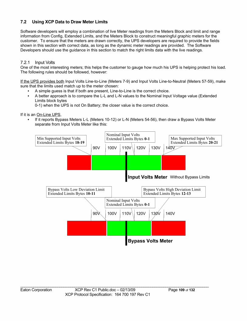
7.2 Using XCP Data to Draw Meter Limits
Software developers will employ a combination of live Meter readings from the Meters Block and limit and range information from Config, Extended Limits, and the Meters Block to construct meaningful graphic meters for the customer. To ensure that the meters are drawn correctly, the UPS developers are required to provide the fields shown in this section with correct data, as long as the dynamic meter readings are provided. The Software Developers should use the guidance in this section to match the right limits data with the live readings.
7.2.1 Input VoltsOne of the most interesting meters; this helps the customer to gauge how much his UPS is helping protect his load. The following rules should be followed, however:
If the UPS provides both Input Volts Line-to-Line (Meters 7-9) and Input Volts Line-to-Neutral (Meters 57-59), make sure that the limits used match up to the meter chosen:
• A simple guess is that if both are present, Line-to-Line is the correct choice.• A better approach is to compare the L-L and L-N values to the Nominal Input Voltage value (Extended
Limits block bytes 0-1) when the UPS is not On Battery; the closer value is the correct choice.
If it is an On-Line UPS,• If it reports Bypass Meters L-L (Meters 10-12) or L-N (Meters 54-56), then draw a Bypass Volts Meter
separate from Input Volts Meter like this:
Min Supported Input VoltsExtended Limits Bytes 18-19
Nominal Input VoltsExtended Limits Bytes 0-1 Max Supported Input Volts
Extended Limits Bytes 20-21
Input Volts Meter
120V 130V110V100V 140V90V
Without Bypass Limits
Nominal Input VoltsExtended Limits Bytes 0-1
Bypass Volts High Deviation LimitExtended Limits Bytes 12-13
Bypass Volts Low Deviation LimitExtended Limits Bytes 10-11
Bypass Volts Meter
120V 130V110V100V 140V90V
_______________________________________________________________________________________Eaton Corporation XCP Rev C1 Public.doc – 02/13/09 Page 109 of 132 XCP Protocol Specification: 164 700 197 Rev C1
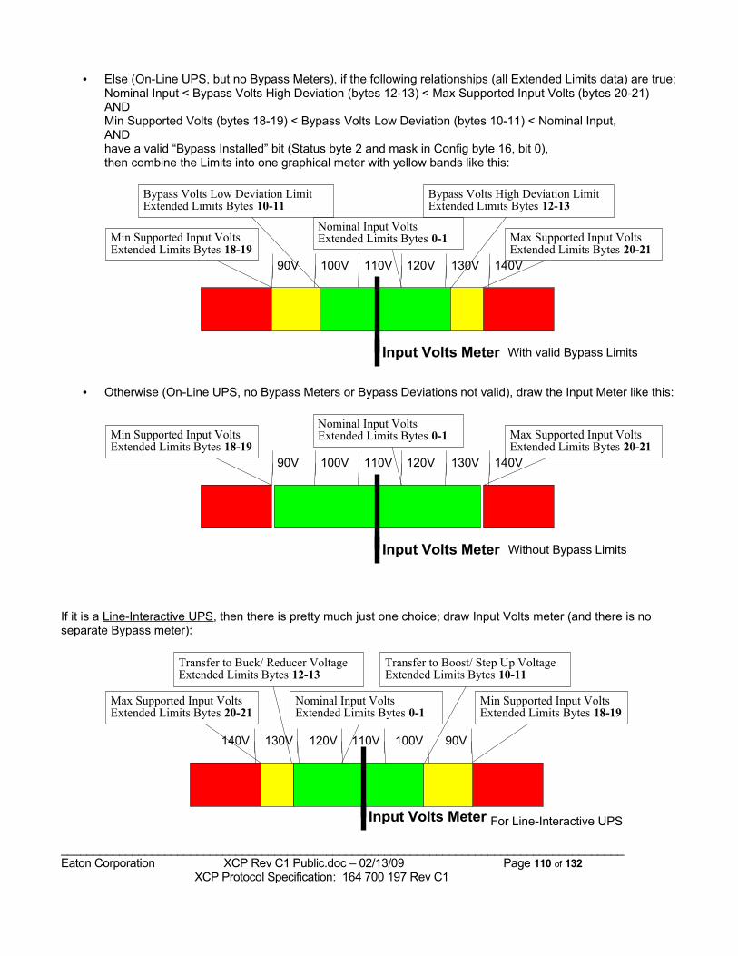
• Else (On-Line UPS, but no Bypass Meters), if the following relationships (all Extended Limits data) are true:Nominal Input < Bypass Volts High Deviation (bytes 12-13) < Max Supported Input Volts (bytes 20-21)ANDMin Supported Volts (bytes 18-19) < Bypass Volts Low Deviation (bytes 10-11) < Nominal Input,AND have a valid “Bypass Installed” bit (Status byte 2 and mask in Config byte 16, bit 0),then combine the Limits into one graphical meter with yellow bands like this:
Min Supported Input VoltsExtended Limits Bytes 18-19
Nominal Input VoltsExtended Limits Bytes 0-1 Max Supported Input Volts
Extended Limits Bytes 20-21
Bypass Volts High Deviation LimitExtended Limits Bytes 12-13
Bypass Volts Low Deviation LimitExtended Limits Bytes 10-11
Input Volts Meter
120V 130V110V100V 140V90V
With valid Bypass Limits
• Otherwise (On-Line UPS, no Bypass Meters or Bypass Deviations not valid), draw the Input Meter like this:
Min Supported Input VoltsExtended Limits Bytes 18-19
Nominal Input VoltsExtended Limits Bytes 0-1 Max Supported Input Volts
Extended Limits Bytes 20-21
Input Volts Meter
120V 130V110V100V 140V90V
Without Bypass Limits
If it is a Line-Interactive UPS, then there is pretty much just one choice; draw Input Volts meter (and there is no separate Bypass meter):
Min Supported Input VoltsExtended Limits Bytes 18-19
Nominal Input VoltsExtended Limits Bytes 0-1
Max Supported Input VoltsExtended Limits Bytes 20-21
Transfer to Buck/ Reducer VoltageExtended Limits Bytes 12-13
Transfer to Boost/ Step Up VoltageExtended Limits Bytes 10-11
Input Volts Meter
120V130V 110V 100V140V 90V
For Line-Interactive UPS
_______________________________________________________________________________________Eaton Corporation XCP Rev C1 Public.doc – 02/13/09 Page 110 of 132 XCP Protocol Specification: 164 700 197 Rev C1
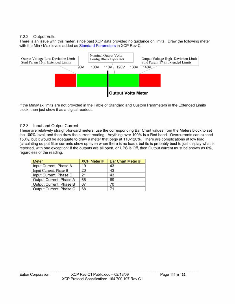
7.2.2 Output VoltsThere is an issue with this meter, since past XCP data provided no guidance on limits. Draw the following meter with the Min / Max levels added as Standard Parameters in XCP Rev C:
Output Voltage Low Deviation LimitStnd Param 16 in Extended Limits
Nominal Output VoltsConfig Block Bytes 8-9 Output Voltage High Deviation Limit
Stnd Param 17 in Extended Limits
Output Volts Meter
120V 130V110V100V 140V90V
If the Min/Max limits are not provided in the Table of Standard and Custom Parameters in the Extended Limits block, then just show it as a digital readout.
7.2.3 Input and Output CurrentThese are relatively straight-forward meters; use the corresponding Bar Chart values from the Meters block to set the 100% level, and then draw the current reading. Anything over 100% is a Red band. Overcurrents can exceed 150%, but it would be adequate to draw a meter that pegs at 110-120%. There are complications at low load (circulating output filter currents show up even when there is no load), but its is probably best to just display what is reported, with one exception: If the outputs are all open, or UPS is Off, then Output current must be shown as 0%, regardless of the reading.
Meter XCP Meter # Bar Chart Meter #Input Current, Phase A 19 43Input Current, Phase B 20 43Input Current, Phase C 21 43Output Current, Phase A 66 69Output Current, Phase B 67 70Output Current, Phase C 68 71
_______________________________________________________________________________________Eaton Corporation XCP Rev C1 Public.doc – 02/13/09 Page 111 of 132 XCP Protocol Specification: 164 700 197 Rev C1

“Bar Chart” value forquantity being Metered
60% 80%40%20% 100%
Eg, Output Current at 85%
Sample Meters, using Bar Chart value
60% 80%40%20% 100%
Eg, Output Current at 110%
7.2.4 Load and Power MetersShow the Output Load for all phases, showing whatever quantity is most limiting (overall VA, overall Watts, or per-phase current):
• If the Outputs are all Open or the UPS status is Off (0x20 or lower), load is fixed at 0%.• If the load is low (< 30%), use Output VA meter #24 and Output VA Bar Chart meter #72, as shown above.• Otherwise, use the greatest of
a) Output current % load per phaseb) Output VA %c) Output Watts %, using Output Watts meter #22 and Nominal “Extended” True Power Rating (Config block bytes 4-5, multiplied by 50)
Input Power and VA meters don’t have nominal values in XCP. While they could be drawn, they probably aren’t too interesting, except for products that only have input power and not output power readings (like the IPDD).
Power Factor meters ALWAYS fall between 0.00 and 1.00, hopefully between 0.70 and 1.00. No nominal values (since they are load dependent). While they could be drawn, they are probably best displayed as a numeric readout, if shown.
_______________________________________________________________________________________Eaton Corporation XCP Rev C1 Public.doc – 02/13/09 Page 112 of 132 XCP Protocol Specification: 164 700 197 Rev C1
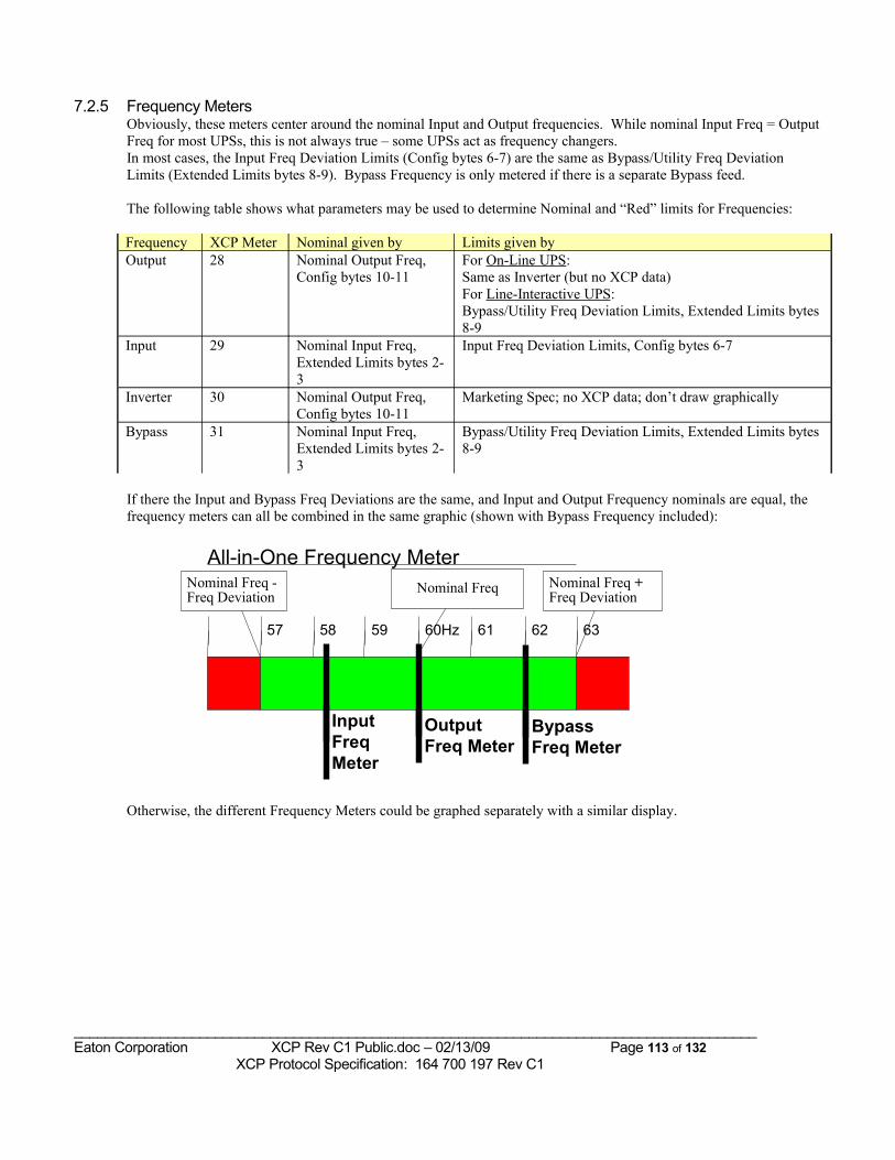
7.2.5 Frequency MetersObviously, these meters center around the nominal Input and Output frequencies. While nominal Input Freq = Output Freq for most UPSs, this is not always true – some UPSs act as frequency changers.In most cases, the Input Freq Deviation Limits (Config bytes 6-7) are the same as Bypass/Utility Freq Deviation Limits (Extended Limits bytes 8-9). Bypass Frequency is only metered if there is a separate Bypass feed.
The following table shows what parameters may be used to determine Nominal and “Red” limits for Frequencies:
Frequency XCP Meter Nominal given by Limits given byOutput 28 Nominal Output Freq,
Config bytes 10-11For On-Line UPS: Same as Inverter (but no XCP data)For Line-Interactive UPS:Bypass/Utility Freq Deviation Limits, Extended Limits bytes 8-9
Input 29 Nominal Input Freq, Extended Limits bytes 2-3
Input Freq Deviation Limits, Config bytes 6-7
Inverter 30 Nominal Output Freq, Config bytes 10-11
Marketing Spec; no XCP data; don’t draw graphically
Bypass 31 Nominal Input Freq, Extended Limits bytes 2-3
Bypass/Utility Freq Deviation Limits, Extended Limits bytes 8-9
If there the Input and Bypass Freq Deviations are the same, and Input and Output Frequency nominals are equal, the frequency meters can all be combined in the same graphic (shown with Bypass Frequency included):
Nominal Freq +Freq Deviation
59 60Hz5857 61
All-in-One Frequency Meter
OutputFreq Meter
62 63
Nominal Freq -Freq Deviation Nominal Freq
BypassFreq Meter
InputFreqMeter
Otherwise, the different Frequency Meters could be graphed separately with a similar display.
_______________________________________________________________________________________Eaton Corporation XCP Rev C1 Public.doc – 02/13/09 Page 113 of 132 XCP Protocol Specification: 164 700 197 Rev C1
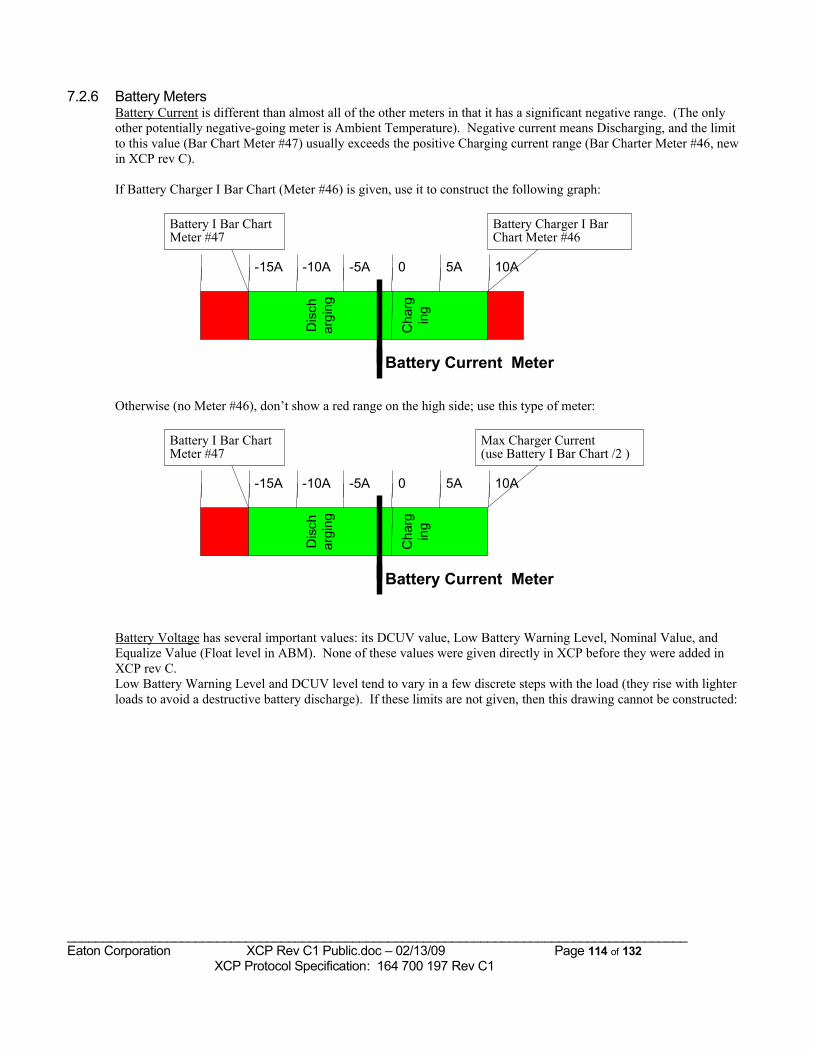
7.2.6 Battery MetersBattery Current is different than almost all of the other meters in that it has a significant negative range. (The only other potentially negative-going meter is Ambient Temperature). Negative current means Discharging, and the limit to this value (Bar Chart Meter #47) usually exceeds the positive Charging current range (Bar Charter Meter #46, new in XCP rev C).
If Battery Charger I Bar Chart (Meter #46) is given, use it to construct the following graph:
Battery Charger I BarChart Meter #46
Dis
char
ging
Cha
rgin
g
-5A 0-10A-15A 5A
Battery Current Meter
10A
Battery I Bar ChartMeter #47
Otherwise (no Meter #46), don’t show a red range on the high side; use this type of meter:
Max Charger Current(use Battery I Bar Chart /2 )
Dis
char
ging
Cha
rgin
g
-5A 0-10A-15A 5A
Battery Current Meter
10A
Battery I Bar ChartMeter #47
Battery Voltage has several important values: its DCUV value, Low Battery Warning Level, Nominal Value, and Equalize Value (Float level in ABM). None of these values were given directly in XCP before they were added in XCP rev C. Low Battery Warning Level and DCUV level tend to vary in a few discrete steps with the load (they rise with lighter loads to avoid a destructive battery discharge). If these limits are not given, then this drawing cannot be constructed:
_______________________________________________________________________________________Eaton Corporation XCP Rev C1 Public.doc – 02/13/09 Page 114 of 132 XCP Protocol Specification: 164 700 197 Rev C1
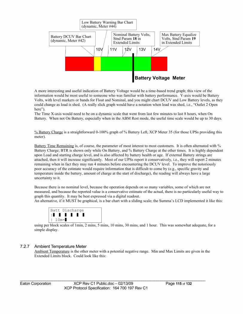
Max Battery EqualizeVolts, Stnd Param 19in Extended Limits
11V 12V10V 13V
Battery Voltage Meter
14V
Battery DCUV Bar Chart(dynamic, Meter #42)
Low Battery Warning Bar Chart(dynamic, Meter #44)
Nominal Battery Volts,Stnd Param 18 inExtended Limits
A more interesting and useful indication of Battery Voltage would be a time-based trend graph; this view of the information would be most useful to someone who was familiar with battery performance. Y-axis would be Battery Volts, with level markers or bands for Float and Nominal, and you might chart DCUV and Low Battery levels, as they could change as load is shed. (A really slick graph would have a notation when load was shed, i.e., “Outlet 2 Open here”).The Time X-axis would need to be on a dynamic scale that went from last few minutes to last 8 hours, when On Battery. When not On Battery, especially when in the ABM Rest mode, the useful time scale would be up to 30 days.
% Battery Charge is a straightforward 0-100% graph of % Battery Left, XCP Meter 35 (for those UPSs providing this meter).
Battery Time Remaining is, of course, the parameter of most interest to most customers. It is often alternated with % Battery Charge; BTR is shown only while On Battery, and % Battery Charge at the other times. It is highly dependent upon Load and starting charge level, and is also affected by battery health or age. If external Battery strings are attached, then it will increase significantly. Most of our UPSs report it conservatively, i.e., they will report 2 minutes remaining when in fact they may run 4 minutes before encountering the DCUV level. To improve the notoriously poor accuracy of the estimate would require information that is difficult to come by (e.g., specific gravity and temperature inside the battery, amount of charge at the start of discharge), the reading will always have a large uncertainty to it.
Because there is no nominal level, because the operation depends on so many variables, some of which are not measured, and because the reported value is a conservative estimate of the actual, there is no particularly useful way to graph this quantity. It may be best expressed via a digital readout.An alternative, if it MUST be graphical, is a bar chart with a sliding scale; the Summa’s LCD implemented it like this:
Batt Discharge|❚ ❚ ❚ ❚ ❚ ❚ | 10m=❚
using per block scales of 1min, 2 mins, 5 mins, 10 mins, 30 mins, and 1 hour. This was somewhat adequate, for a simple display.
7.2.7 Ambient Temperature MeterAmbient Temperature is the other meter with a potential negative range. Min and Max Limits are given in the Extended Limits block. Could look like this:
_______________________________________________________________________________________Eaton Corporation XCP Rev C1 Public.doc – 02/13/09 Page 115 of 132 XCP Protocol Specification: 164 700 197 Rev C1
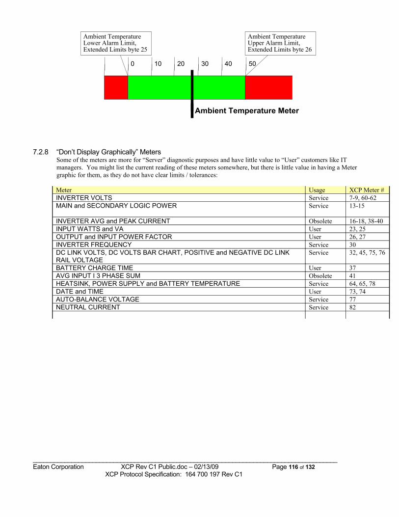
Ambient TemperatureUpper Alarm Limit,Extended Limits byte 26
20 30100 40
Ambient Temperature Meter
50
Ambient TemperatureLower Alarm Limit,Extended Limits byte 25
7.2.8 “Don’t Display Graphically” MetersSome of the meters are more for “Server” diagnostic purposes and have little value to “User” customers like IT managers. You might list the current reading of these meters somewhere, but there is little value in having a Meter graphic for them, as they do not have clear limits / tolerances:
Meter Usage XCP Meter #INVERTER VOLTS Service 7-9, 60-62MAIN and SECONDARY LOGIC POWER Service 13-15
INVERTER AVG and PEAK CURRENT Obsolete 16-18, 38-40INPUT WATTS and VA User 23, 25OUTPUT and INPUT POWER FACTOR User 26, 27INVERTER FREQUENCY Service 30DC LINK VOLTS, DC VOLTS BAR CHART, POSITIVE and NEGATIVE DC LINK RAIL VOLTAGE
Service 32, 45, 75, 76
BATTERY CHARGE TIME User 37AVG INPUT I 3 PHASE SUM Obsolete 41HEATSINK, POWER SUPPLY and BATTERY TEMPERATURE Service 64, 65, 78DATE and TIME User 73, 74AUTO-BALANCE VOLTAGE Service 77NEUTRAL CURRENT Service 82
_______________________________________________________________________________________Eaton Corporation XCP Rev C1 Public.doc – 02/13/09 Page 116 of 132 XCP Protocol Specification: 164 700 197 Rev C1
7.3 Notes to Communication Software Developers
To create correct, reliable, and robust software to communicate with Powerware UPSs, always consider the following points in your software design and development:
7.3.1 Powerware UPS CompliancesThis document describes HOW Powerware UPSs are to implement communication features IF they implement them. Due to market demands or cost limitations, there is no Powerware UPS which implements all or even most of the features shown in this specification. For the same reasons, some UPS implementations deviate from the preferred implementation described in this specification (e.g., Battery Time Remaining meter may only be meaningful while On Battery). Your ultimate guide to which features are implemented and how for a given UPS is from the XCP Compliance Document for that UPS.
7.3.2 Parsing Data BlocksNever rely on data items to be found in fixed positions in the ID (except first byte), Meters, or Alarms data blocks. You must always parse the ID block and use the information there to find the positions of Meters and Alarms. Note that the absolute positions of the Meter and Alarm Maps in the ID block can vary (e.g., as the ID Message changes its length), as can the maps’ lengths (e.g., as new items are added in subsequent XCP revisions). Also, for some fixed data blocks, a UPS may implement something shorter than the fully specified block; you must check the length contained in the XCP response and not “use” fields located beyond the end of the given data.
7.3.3 Deriving Output MetersIf the Output position is not directly sensed, its meters should be derived by the software as
a) equal to Inverter if On Inverter, or b) equal to Bypass if On Bypass, or c) equal to 0 if the Output breaker is open
(adjustments for output transformers and filters necessary).
7.3.4 XCP Changes with UPS RevisionsThe exact Meters and Alarms implemented in a UPS, and certain other features, may vary from revision to revision, even within a given product line. See the section on “Parsing Data Blocks”.
7.3.5 Testing of Communication SoftwareThere is no substitute for direct testing of the UPS(s) that the Communication Software is intended to work with; although this specification, the compliance documents, and the XCP simulator provide much useful verification of design, they don’t emulate the timing of the actual UPS responses. Furthermore, to validate that your design is correct and robust, you should plan to test with at least two models of Powerware UPSs; these two models should be as different as possible, ideally the latest designed single-phase machine and one three-phase machine with an Event History Log .
7.3.6 Provision for Future Additions in UPS ImplementationCommunication devices and software should be designed to permit the UPS to extend the data or command sets in the future without interfering with the data collection and control of the known features.
_______________________________________________________________________________________Eaton Corporation XCP Rev C1 Public.doc – 02/13/09 Page 117 of 132 XCP Protocol Specification: 164 700 197 Rev C1
7.3.7 When to initiate Normal and Panic OS Shutdown
Most monitoring software has, as its most important and basic function, a function to do a “Normal” orderly shutdown of the Operating System; there is always a period of a few minutes or many seconds before the software will even begin to consider doing this. However, it sometimes also happens that there is not sufficient time for a full, orderly shutdown, and so the software must try to do a “Panic” shut down the Operating System as well as it can in the short time left, and it must begin to do so immediately, i.e., without delay.
7.3.7.1 Shutdown Recommendations for Software DevelopersThe following are the recommended conditions to initiate Normal or Panic Shutdown:
Normal Shutdown Countdown begin = OnBatteryAlarm (#168) || ( Pending Shutdown delay <= Warning Time + OS Shutdown Time )
andPanic Shutdown begin =
Low Battery (Alarm #58) && OnBatteryAlarm (#168) || Shutdown Imminent Alarm (#55) || Automatic Shutdown Pending (#206 ) ||(Shutdown delay <= OS Shutdown Time ) )
Warning Time is the delay that Shutdown Software waits while On Battery before beginning its OS Shutdown, during which it usually sends notices to users (E.g., “Shutdown in 2 minutes; please close your applications”)
7.3.7.2 Shutdown Support Requirements for UPS Developers
To ensure that Shutdown Software can properly detect and manage shutdown, the implementation of these alarms is now mandatory for all UPSs:
• Low Battery (Alarm #58)• OnBatteryAlarm (#168)
And the following alarms are required if the UPS can recognize and act on conditions that would cause a shutdown in less than Low Battery Warning time:
• Shutdown Imminent Alarm (#55)• Automatic Shutdown Pending (#206 )
7.4 Considerations for OEMs and foreign languagesNothing specified at this time; most protocol features now are expressed in Binary values, not ASCII English, to aid communication software in supporting foreign languages.
7.5 Process for revising this Protocol• To the extent possible, this protocol should make it simple to add new data points, features or
controls in the future, still in keeping with the spirit of the released XCP specification.
_______________________________________________________________________________________Eaton Corporation XCP Rev C1 Public.doc – 02/13/09 Page 118 of 132 XCP Protocol Specification: 164 700 197 Rev C1
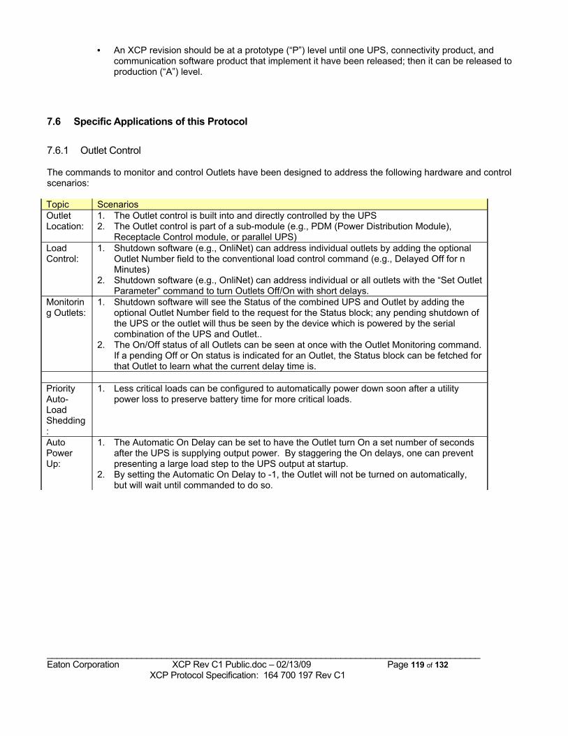
• An XCP revision should be at a prototype (“P”) level until one UPS, connectivity product, and communication software product that implement it have been released; then it can be released to production (“A”) level.
7.6 Specific Applications of this Protocol
7.6.1 Outlet Control
The commands to monitor and control Outlets have been designed to address the following hardware and control scenarios:
Topic ScenariosOutlet Location:
1. The Outlet control is built into and directly controlled by the UPS2. The Outlet control is part of a sub-module (e.g., PDM (Power Distribution Module),
Receptacle Control module, or parallel UPS)Load Control:
1. Shutdown software (e.g., OnliNet) can address individual outlets by adding the optional Outlet Number field to the conventional load control command (e.g., Delayed Off for n Minutes)
2. Shutdown software (e.g., OnliNet) can address individual or all outlets with the “Set Outlet Parameter” command to turn Outlets Off/On with short delays.
Monitoring Outlets:
1. Shutdown software will see the Status of the combined UPS and Outlet by adding the optional Outlet Number field to the request for the Status block; any pending shutdown of the UPS or the outlet will thus be seen by the device which is powered by the serial combination of the UPS and Outlet..
2. The On/Off status of all Outlets can be seen at once with the Outlet Monitoring command. If a pending Off or On status is indicated for an Outlet, the Status block can be fetched for that Outlet to learn what the current delay time is.
Priority Auto-LoadShedding:
1. Less critical loads can be configured to automatically power down soon after a utility power loss to preserve battery time for more critical loads.
Auto Power Up:
1. The Automatic On Delay can be set to have the Outlet turn On a set number of seconds after the UPS is supplying output power. By staggering the On delays, one can prevent presenting a large load step to the UPS output at startup.
2. By setting the Automatic On Delay to -1, the Outlet will not be turned on automatically, but will wait until commanded to do so.
_______________________________________________________________________________________Eaton Corporation XCP Rev C1 Public.doc – 02/13/09 Page 119 of 132 XCP Protocol Specification: 164 700 197 Rev C1
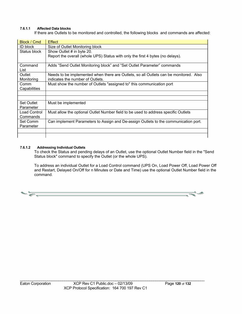
7.6.1.1 Affected Data blocksIf there are Outlets to be monitored and controlled, the following blocks and commands are affected:
Block / Cmd EffectID block Size of Outlet Monitoring blockStatus block Show Outlet # in byte 20.
Report the overall (whole UPS) Status with only the first 4 bytes (no delays).
Command List
Adds “Send Outlet Monitoring block” and “Set Outlet Parameter” commands
Outlet Monitoring
Needs to be implemented when there are Outlets, so all Outlets can be monitored. Also indicates the number of Outlets.
Comm Capabilities
Must show the number of Outlets "assigned to" this communication port
Set Outlet Parameter
Must be implemented
Load Control Commands
Must allow the optional Outlet Number field to be used to address specific Outlets
Set Comm Parameter
Can implement Parameters to Assign and De-assign Outlets to the communication port.
7.6.1.2 Addressing Individual OutletsTo check the Status and pending delays of an Outlet, use the optional Outlet Number field in the "Send Status block" command to specify the Outlet (or the whole UPS).
To address an individual Outlet for a Load Control command (UPS On, Load Power Off, Load Power Off and Restart, Delayed On/Off for n Minutes or Date and Time) use the optional Outlet Number field in the command.
_______________________________________________________________________________________Eaton Corporation XCP Rev C1 Public.doc – 02/13/09 Page 120 of 132 XCP Protocol Specification: 164 700 197 Rev C1
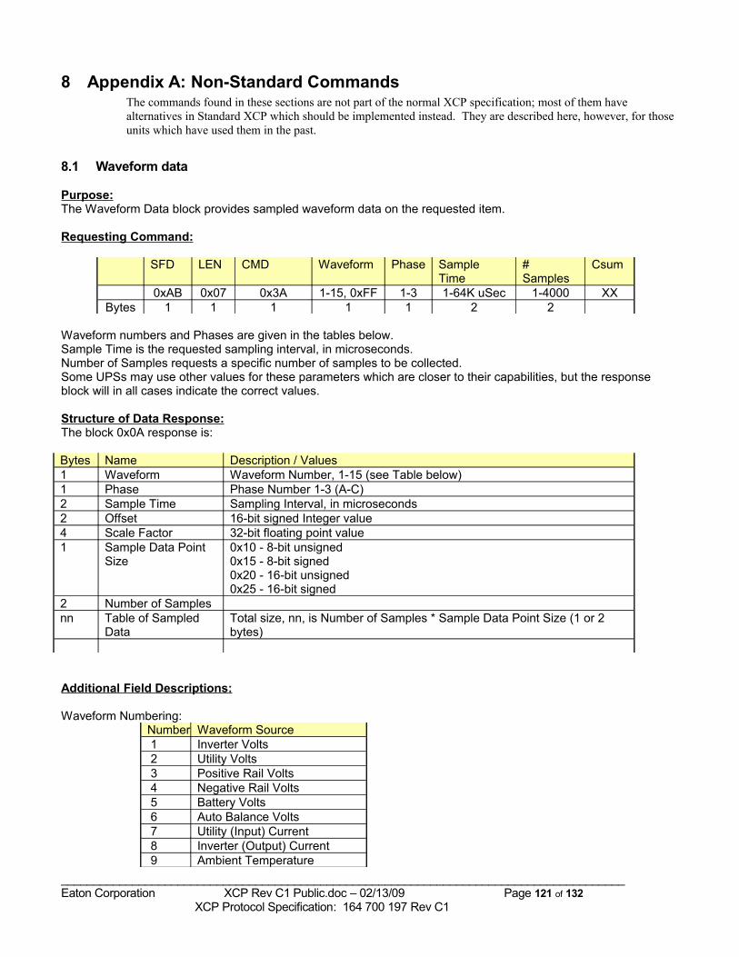
8 Appendix A: Non-Standard CommandsThe commands found in these sections are not part of the normal XCP specification; most of them have alternatives in Standard XCP which should be implemented instead. They are described here, however, for those units which have used them in the past.
8.1 Waveform data
Purpose:The Waveform Data block provides sampled waveform data on the requested item.
Requesting Command:
SFD LEN CMD Waveform Phase Sample Time
# Samples
Csum
0xAB 0x07 0x3A 1-15, 0xFF 1-3 1-64K uSec 1-4000 XXBytes 1 1 1 1 1 2 2
Waveform numbers and Phases are given in the tables below.Sample Time is the requested sampling interval, in microseconds.Number of Samples requests a specific number of samples to be collected. Some UPSs may use other values for these parameters which are closer to their capabilities, but the response block will in all cases indicate the correct values.
Structure of Data Response:The block 0x0A response is:
Bytes Name Description / Values1 Waveform Waveform Number, 1-15 (see Table below)1 Phase Phase Number 1-3 (A-C)2 Sample Time Sampling Interval, in microseconds2 Offset 16-bit signed Integer value4 Scale Factor 32-bit floating point value1 Sample Data Point
Size0x10 - 8-bit unsigned0x15 - 8-bit signed0x20 - 16-bit unsigned0x25 - 16-bit signed
2 Number of Samplesnn Table of Sampled
DataTotal size, nn, is Number of Samples * Sample Data Point Size (1 or 2 bytes)
Additional Field Descriptions:
Waveform Numbering:Number Waveform Source 1 Inverter Volts 2 Utility Volts 3 Positive Rail Volts 4 Negative Rail Volts 5 Battery Volts 6 Auto Balance Volts 7 Utility (Input) Current 8 Inverter (Output) Current 9 Ambient Temperature
_______________________________________________________________________________________Eaton Corporation XCP Rev C1 Public.doc – 02/13/09 Page 121 of 132 XCP Protocol Specification: 164 700 197 Rev C1
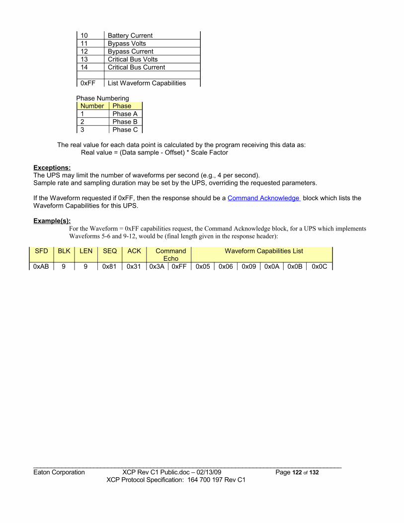
10 Battery Current11 Bypass Volts12 Bypass Current13 Critical Bus Volts14 Critical Bus Current
0xFF List Waveform Capabilities
Phase NumberingNumber Phase1 Phase A2 Phase B3 Phase C
The real value for each data point is calculated by the program receiving this data as:Real value = (Data sample - Offset) * Scale Factor
Exceptions:The UPS may limit the number of waveforms per second (e.g., 4 per second).Sample rate and sampling duration may be set by the UPS, overriding the requested parameters.
If the Waveform requested if 0xFF, then the response should be a Command Acknowledge block which lists the Waveform Capabilities for this UPS.
Example(s):For the Waveform = 0xFF capabilities request, the Command Acknowledge block, for a UPS which implements Waveforms 5-6 and 9-12, would be (final length given in the response header):
SFD BLK LEN SEQ ACK Command Echo
Waveform Capabilities List
0xAB 9 9 0x81 0x31 0x3A 0xFF 0x05 0x06 0x09 0x0A 0x0B 0x0C
_______________________________________________________________________________________Eaton Corporation XCP Rev C1 Public.doc – 02/13/09 Page 122 of 132 XCP Protocol Specification: 164 700 197 Rev C1
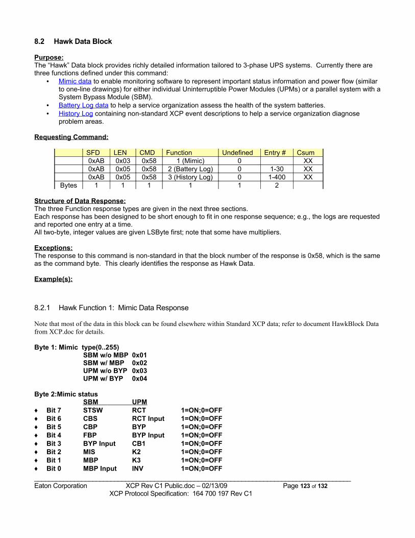
8.2 Hawk Data Block
Purpose:The “Hawk” Data block provides richly detailed information tailored to 3-phase UPS systems. Currently there are three functions defined under this command:
• Mimic data to enable monitoring software to represent important status information and power flow (similar to one-line drawings) for either individual Uninterruptible Power Modules (UPMs) or a parallel system with a System Bypass Module (SBM).
• Battery Log data to help a service organization assess the health of the system batteries.• History Log containing non-standard XCP event descriptions to help a service organization diagnose
problem areas.
Requesting Command:
SFD LEN CMD Function Undefined Entry # Csum0xAB 0x03 0x58 1 (Mimic) 0 XX0xAB 0x05 0x58 2 (Battery Log) 0 1-30 XX0xAB 0x05 0x58 3 (History Log) 0 1-400 XX
Bytes 1 1 1 1 1 2
Structure of Data Response:The three Function response types are given in the next three sections.Each response has been designed to be short enough to fit in one response sequence; e.g., the logs are requested and reported one entry at a time.All two-byte, integer values are given LSByte first; note that some have multipliers.
Exceptions:The response to this command is non-standard in that the block number of the response is 0x58, which is the same as the command byte. This clearly identifies the response as Hawk Data.
Example(s):
8.2.1 Hawk Function 1: Mimic Data Response
Note that most of the data in this block can be found elsewhere within Standard XCP data; refer to document HawkBlock Data from XCP.doc for details.
Byte 1: Mimic type(0..255)SBM w/o MBP 0x01SBM w/ MBP 0x02UPM w/o BYP 0x03UPM w/ BYP 0x04
Byte 2:Mimic statusSBM UPM
♦ Bit 7 STSW RCT 1=ON;0=OFF♦ Bit 6 CBS RCT Input 1=ON;0=OFF♦ Bit 5 CBP BYP 1=ON;0=OFF♦ Bit 4 FBP BYP Input 1=ON;0=OFF♦ Bit 3 BYP Input CB1 1=ON;0=OFF♦ Bit 2 MIS K2 1=ON;0=OFF♦ Bit 1 MBP K3 1=ON;0=OFF♦ Bit 0 MBP Input INV 1=ON;0=OFF_______________________________________________________________________________________Eaton Corporation XCP Rev C1 Public.doc – 02/13/09 Page 123 of 132 XCP Protocol Specification: 164 700 197 Rev C1
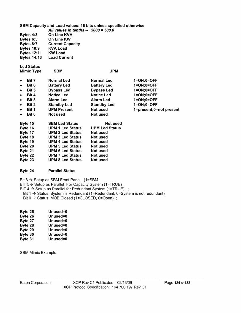
SBM Capacity and Load values: 16 bits unless specified otherwiseAll values in tenths -- 5000 = 500.0
Bytes 4:3 On Line KVABytes 6:5 On Line KWBytes 8:7 Current CapacityBytes 10:9 KVA LoadBytes 12:11 KW LoadBytes 14:13 Load Current
Led StatusMimic Type SBM UPM
♦ Bit 7 Normal Led Normal Led 1=ON;0=OFF♦ Bit 6 Battery Led Battery Led 1=ON;0=OFF♦ Bit 5 Bypass Led Bypass Led 1=ON;0=OFF♦ Bit 4 Notice Led Notice Led 1=ON;0=OFF♦ Bit 3 Alarm Led Alarm Led 1=ON;0=OFF♦ Bit 2 Standby Led Standby Led 1=ON;0=OFF♦ Bit 1 UPM Present Not used 1=present;0=not present♦ Bit 0 Not used Not used
Byte 15 SBM Led Status Not usedByte 16 UPM 1 Led Status UPM Led StatusByte 17 UPM 2 Led Status Not usedByte 18 UPM 3 Led Status Not usedByte 19 UPM 4 Led Status Not usedByte 20 UPM 5 Led Status Not usedByte 21 UPM 6 Led Status Not usedByte 22 UPM 7 Led Status Not usedByte 23 UPM 8 Led Status Not used
Byte 24 Parallel Status
Bit 6 Setup as SBM Front Panel (1=SBMBIT 5 Setup as Parallel For Capacity System (1=TRUE) BIT 4 Setup as Parallel for Redundant System (1=TRUE) ; Bit 1 Status: System is Redundant (1=Redundant, 0=System is not redundant) Bit 0 Status: MOB Closed (1=CLOSED, 0=Open) ;
Byte 25 Unused=0Byte 26 Unused=0Byte 27 Unused=0Byte 28 Unused=0Byte 29 Unused=0Byte 30 Unused=0Byte 31 Unused=0
SBM Mimic Example:
_______________________________________________________________________________________Eaton Corporation XCP Rev C1 Public.doc – 02/13/09 Page 124 of 132 XCP Protocol Specification: 164 700 197 Rev C1
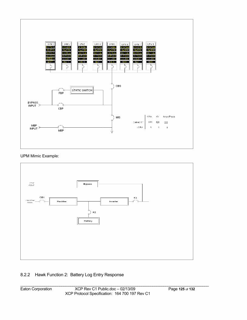
UPM Mimic Example:
8.2.2 Hawk Function 2: Battery Log Entry Response
_______________________________________________________________________________________Eaton Corporation XCP Rev C1 Public.doc – 02/13/09 Page 125 of 132 XCP Protocol Specification: 164 700 197 Rev C1
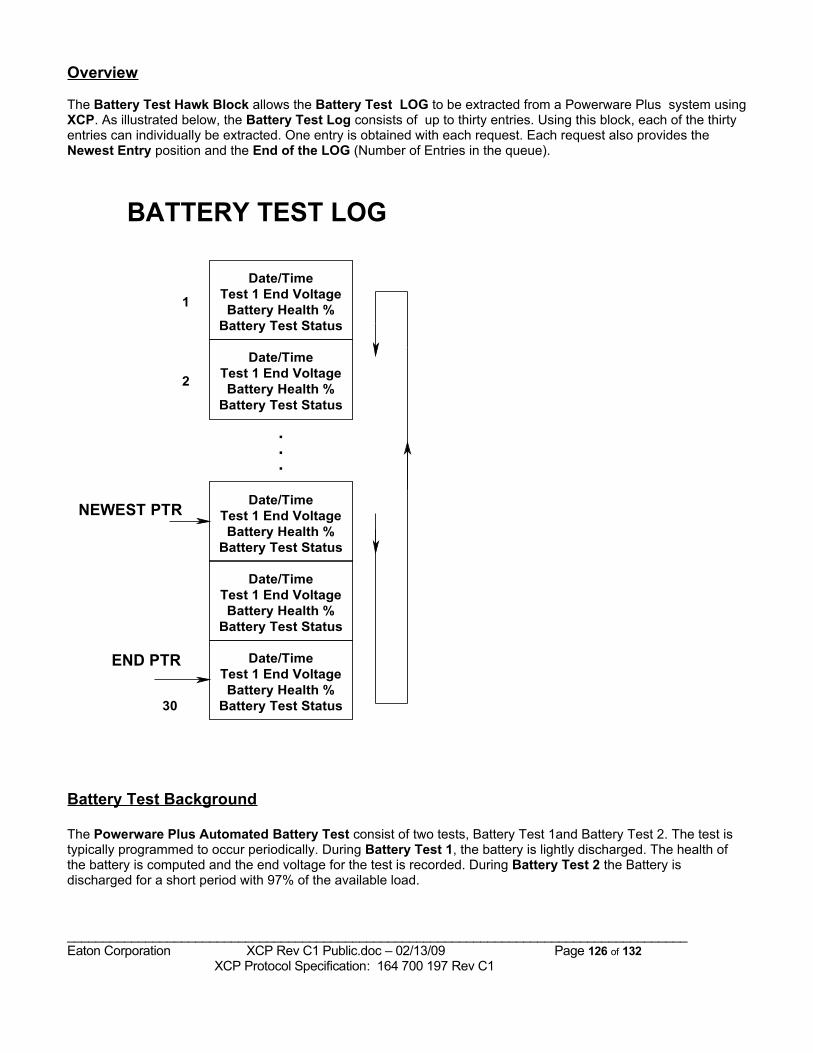
Overview
The Battery Test Hawk Block allows the Battery Test LOG to be extracted from a Powerware Plus system using XCP. As illustrated below, the Battery Test Log consists of up to thirty entries. Using this block, each of the thirty entries can individually be extracted. One entry is obtained with each request. Each request also provides the Newest Entry position and the End of the LOG (Number of Entries in the queue).
Date/TimeTest 1 End VoltageBattery Health %
Battery Test Status
Date/TimeTest 1 End VoltageBattery Health %
Battery Test Status
Date/TimeTest 1 End VoltageBattery Health %
Battery Test Status
.
.
.
Date/TimeTest 1 End VoltageBattery Health %
Battery Test Status
Date/TimeTest 1 End VoltageBattery Health %
Battery Test Status
1
2
END PTR
30
BATTERY TEST LOG
NEWEST PTR
Battery Test Background
The Powerware Plus Automated Battery Test consist of two tests, Battery Test 1and Battery Test 2. The test is typically programmed to occur periodically. During Battery Test 1, the battery is lightly discharged. The health of the battery is computed and the end voltage for the test is recorded. During Battery Test 2 the Battery is discharged for a short period with 97% of the available load.
_______________________________________________________________________________________Eaton Corporation XCP Rev C1 Public.doc – 02/13/09 Page 126 of 132 XCP Protocol Specification: 164 700 197 Rev C1
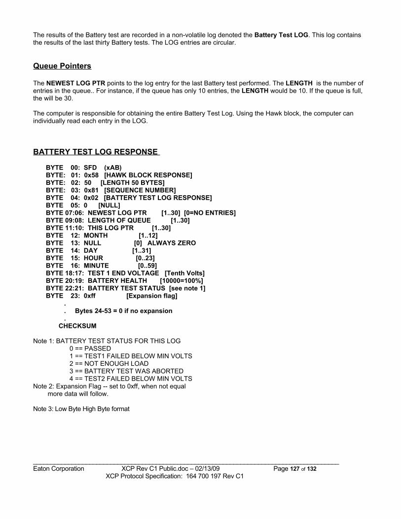
The results of the Battery test are recorded in a non-volatile log denoted the Battery Test LOG. This log contains the results of the last thirty Battery tests. The LOG entries are circular.
Queue Pointers
The NEWEST LOG PTR points to the log entry for the last Battery test performed. The LENGTH is the number of entries in the queue.. For instance, if the queue has only 10 entries, the LENGTH would be 10. If the queue is full, the will be 30.
The computer is responsible for obtaining the entire Battery Test Log. Using the Hawk block, the computer can individually read each entry in the LOG.
BATTERY TEST LOG RESPONSE
BYTE 00: SFD (xAB) BYTE: 01: 0x58 [HAWK BLOCK RESPONSE] BYTE: 02: 50 [LENGTH 50 BYTES] BYTE: 03: 0x81 [SEQUENCE NUMBER] BYTE 04: 0x02 [BATTERY TEST LOG RESPONSE] BYTE 05: 0 [NULL] BYTE 07:06: NEWEST LOG PTR [1..30] [0=NO ENTRIES] BYTE 09:08: LENGTH OF QUEUE [1..30] BYTE 11:10: THIS LOG PTR [1..30] BYTE 12: MONTH [1..12] BYTE 13: NULL [0] ALWAYS ZERO BYTE 14: DAY [1..31] BYTE 15: HOUR [0..23] BYTE 16: MINUTE [0..59] BYTE 18:17: TEST 1 END VOLTAGE [Tenth Volts] BYTE 20:19: BATTERY HEALTH [10000=100%] BYTE 22:21: BATTERY TEST STATUS [see note 1] BYTE 23: 0xff [Expansion flag] . . Bytes 24-53 = 0 if no expansion . CHECKSUM
Note 1: BATTERY TEST STATUS FOR THIS LOG 0 == PASSED 1 == TEST1 FAILED BELOW MIN VOLTS 2 == NOT ENOUGH LOAD 3 == BATTERY TEST WAS ABORTED 4 == TEST2 FAILED BELOW MIN VOLTSNote 2: Expansion Flag -- set to 0xff, when not equal more data will follow.
Note 3: Low Byte High Byte format
_______________________________________________________________________________________Eaton Corporation XCP Rev C1 Public.doc – 02/13/09 Page 127 of 132 XCP Protocol Specification: 164 700 197 Rev C1
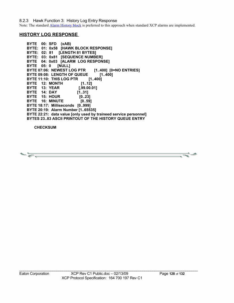
8.2.3 Hawk Function 3: History Log Entry ResponseNote: The standard Alarm History block is preferred to this approach when standard XCP alarms are implemented.
HISTORY LOG RESPONSE
BYTE 00: SFD (xAB) BYTE: 01: 0x58 [HAWK BLOCK RESPONSE] BYTE: 02: 81 [LENGTH 81 BYTES] BYTE: 03: 0x81 [SEQUENCE NUMBER] BYTE 04: 0x03 [ALARM LOG RESPONSE] BYTE 05: 0 [NULL] BYTE 07:06: NEWEST LOG PTR [1..400] [0=NO ENTRIES] BYTE 09:08: LENGTH OF QUEUE [1..400] BYTE 11:10: THIS LOG PTR [1..400] BYTE 12: MONTH [1..12] BYTE 13: YEAR [,99.00.01] BYTE 14: DAY [1..31] BYTE 15: HOUR [0..23] BYTE 16: MINUTE [0..59] BYTE 18:17: Milliseconds [0..999] BYTE 20:19: Alarm Number [1..65535] BYTE 22:21: data value [only used by traineed service personnel] BYTES 23..83 ASCII PRINTOUT OF THE HISTORY QUEUE ENTRY
CHECKSUM
_______________________________________________________________________________________Eaton Corporation XCP Rev C1 Public.doc – 02/13/09 Page 128 of 132 XCP Protocol Specification: 164 700 197 Rev C1
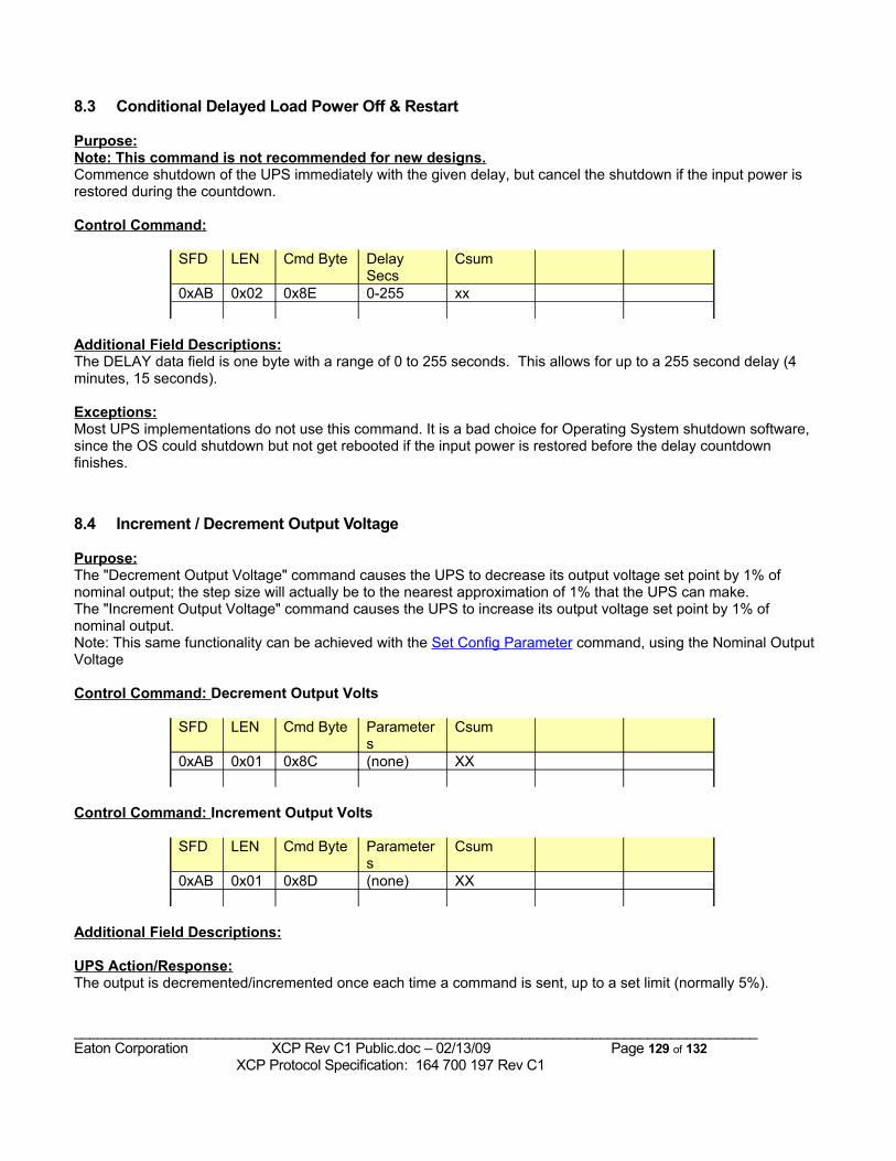
8.3 Conditional Delayed Load Power Off & Restart
Purpose:Note: This command is not recommended for new designs.Commence shutdown of the UPS immediately with the given delay, but cancel the shutdown if the input power is restored during the countdown.
Control Command:
SFD LEN Cmd Byte Delay Secs
Csum
0xAB 0x02 0x8E 0-255 xx
Additional Field Descriptions:The DELAY data field is one byte with a range of 0 to 255 seconds. This allows for up to a 255 second delay (4 minutes, 15 seconds).
Exceptions:Most UPS implementations do not use this command. It is a bad choice for Operating System shutdown software, since the OS could shutdown but not get rebooted if the input power is restored before the delay countdown finishes.
8.4 Increment / Decrement Output Voltage
Purpose:The "Decrement Output Voltage" command causes the UPS to decrease its output voltage set point by 1% of nominal output; the step size will actually be to the nearest approximation of 1% that the UPS can make.The "Increment Output Voltage" command causes the UPS to increase its output voltage set point by 1% of nominal output.Note: This same functionality can be achieved with the Set Config Parameter command, using the Nominal Output Voltage
Control Command: Decrement Output Volts
SFD LEN Cmd Byte Parameters
Csum
0xAB 0x01 0x8C (none) XX
Control Command: Increment Output Volts
SFD LEN Cmd Byte Parameters
Csum
0xAB 0x01 0x8D (none) XX
Additional Field Descriptions:
UPS Action/Response:The output is decremented/incremented once each time a command is sent, up to a set limit (normally 5%).
_______________________________________________________________________________________Eaton Corporation XCP Rev C1 Public.doc – 02/13/09 Page 129 of 132 XCP Protocol Specification: 164 700 197 Rev C1

The value for "Nominal Output Voltage" reported in the Config block is not altered by this command, but the "Output Voltage Adjustment Setting" in the Config block shows the change.
Exceptions:
Example(s):
_______________________________________________________________________________________Eaton Corporation XCP Rev C1 Public.doc – 02/13/09 Page 130 of 132 XCP Protocol Specification: 164 700 197 Rev C1
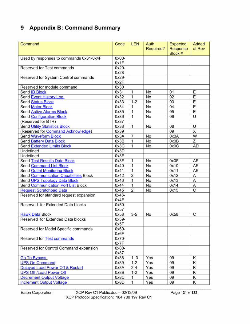
9 Appendix B: Command Summary
Command Code LEN AuthRequired?
Expected Response Block #
Added at Rev
Used by responses to commands 0x31-0x4F 0x00-0x1F
Reserved for Test commands 0x20-0x28
Reserved for System Control commands 0x29-0x2F
Reserved for module command 0x30Send ID Block 0x31 1 No 01 ESend Event History Log 0x32 1 No 02 ESend Status Block 0x33 1-2 No 03 ESend Meter Block 0x34 1 No 04 ESend Active Alarms Block 0x35 1 No 05 ESend Configuration Block 0x36 1 No 06 U(Reserved for BTR) 0x37Send Utility Statistics Block 0x38 1 No 08 U(Reserved for Command Acknowledge) 0x39 09 XSend Waveform Block 0x3A 7 No 0x0A WSend Battery Data Block 0x3B 1 No 0x0B ZSend Extended Limits Block 0x3C 1 No 0x0C ADUndefined 0x3DUndefined 0x3ESend Test Results Data Block 0x3F 1 No 0x0F AESend Command List Block 0x40 1 No 0x10 AESend Outlet Monitoring Block 0x41 1 No 0x11 AESend Communication Capabilities Block 0x42 2 No 0x12 ASend UPS Topology Data Block 0x43 1 No 0x13 ASend Communication Port List Block 0x44 1 No 0x14 ARequest Scratchpad Data 0x45 2 No 0x15 CReserved for standard request expansion 0x46-
0x4FReserved for Extended Data blocks 0x50-
0x57Hawk Data Block 0x58 3-5 No 0x58 CReserved for Extended Data blocks 0x59-
0x5FReserved for Model Specific commands 0x60-
0x6FReserved for Test commands 0x70-
0x7FReserved for Control Command expansion 0x80-
0x87Go To Bypass 0x88 1, 3 Yes 09 KUPS On Command 0x89 1-2 Yes 09 KDelayed Load Power Off & Restart 0x8A 2-4 Yes 09 KUPS Off /Load Power Off 0x8B 1-2 Yes 09 KDecrement Output Voltage 0x8C 1 Yes 09 KIncrement Output Voltage 0x8D 1 Yes 09 K_______________________________________________________________________________________Eaton Corporation XCP Rev C1 Public.doc – 02/13/09 Page 131 of 132 XCP Protocol Specification: 164 700 197 Rev C1
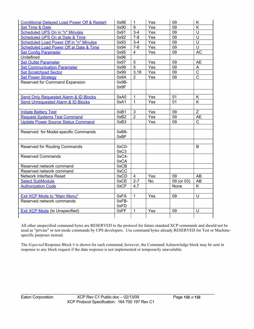
Conditional Delayed Load Power Off & Restart 0x8E 1 Yes 09 KSet Time & Date 0x90 9 Yes 09 KScheduled UPS On in "n" Minutes 0x91 3-4 Yes 09 UScheduled UPS On at Date & Time 0x92 7-8 Yes 09 UScheduled Load Power Off in "n" Minutes 0x93 3-4 Yes 09 UScheduled Load Power Off at Date & Time 0x94 7-8 Yes 09 USet Config Parameter 0x95 4 Yes 09 ACUndefined 0x96Set Outlet Parameter 0x97 5 Yes 09 AESet Communication Parameter 0x98 5 Yes 09 ASet Scratchpad Sector 0x99 3,18 Yes 09 CSet Power Strategy 0x9A 2 Yes 09 CReserved for Command Expansion 0x9B-
0x9F
Send Only Requested Alarm & ID Blocks 0xA0 1 Yes 01 KSend Unrequested Alarm & ID Blocks 0xA1 1 Yes 01 K
Initiate Battery Test 0xB1 3 Yes 09 ZRequest Systems Test Command 0xB2 2 Yes 09 AEUpdate Power Source Status Command 0xB3 Yes 09 C
Reserved for Model-specific Commands 0xB8- 0xBF
Reserved for Routing Commands 0xC0-0xC3
B
Reserved Commands 0xC4-0xCA
Reserved network command 0xCBReserved network command 0xCCNetwork Interface Reset 0xCD 4 Yes 09 ABSelect SubModule 0xCE 2-7 No 09 (or 03) ABAuthorization Code 0xCF 4,7 None K
Exit XCP Mode to "Main Menu" 0xFA 1 Yes 09 UReserved network commands 0xFB-
0xFDExit XCP Mode (to Unspecified) 0xFF 1 Yes 09 U
All other unspecified command bytes are RESERVED to the protocol for future standard XCP commands and should not be used as "private" or test mode commands by UPS developers. Use command bytes already RESERVED for Test or Machine-specific purposes instead.
The Expected Response Block # is shown for each command; however, the Command Acknowledge block may be sent in response to any block request if the data response is not implemented or temporarily unavailable.
_______________________________________________________________________________________Eaton Corporation XCP Rev C1 Public.doc – 02/13/09 Page 132 of 132 XCP Protocol Specification: 164 700 197 Rev C1