Embed Size (px)
Citation preview
XC650CX (v. 3.4)
1592001430 XC650CX GB r3.4 11.12.2018 XC650CX 2/54
INDEX
1. BEFORE PROCEEDING 5 1.1 CHECK THE SW REL. OF THE XC650CX 5
2. GENERAL WARNING 5 2.1 PLEASE READ BEFORE USING THIS MANUAL 5
2.2 SAFETY PRECAUTIONS 5
3. GENERAL DESCRIPTION 5
4. COMPONENTS RELATED TO THE XC650CX 6 4.1 CW15KIT AND CW25KIT: WIRING KITS 7 4.2 CABCJ15 OR CABCJ30: 2 PIN CONNECTORS 7 4.3 PP07, PP11, PP30 PP50: 4÷20MA PRESSURE TRANSDUCERS 7 4.4 XJ485CX: TTL / RS485 SERIAL CONVERTER 7
5. WIRING & ELECTRICAL CONNECTIONS 8 5.1 GENERAL WARNINGS 8 5.2 WIRING CONNECTIONS 8 5.3 PROBES CONNECTION 8 5.4 LOAD CONNECTIONS 9 5.5 SAFETY AND CONFIGURABLE DIGITAL INPUTS – FREE VOLTAGE 10 5.6 ANALOG OUTPUT CONNECTION 10 5.7 HOW TO CONNECT MONITORING SYSTEM - RS485 SERIAL LINE 11
6. MOUNTING & INSTALLATION 11
7. FIRST INSTALLATION 12 7.1 HOW TO SET THE KIND OF GAS 12 7.2 HOW TO SET THE RANGE OF THE PRESSURE PROBES 12
8. USER INTERFACE 13 8.1 DISPLAYING 13 8.2 KEYBOARD 13 8.3 ICONS 14
9. HOW TO SEE AND MODIFY THE SET POINT(S) 15 9.1 HOW TO SEE THE SET POINT OF COMPRESSORS AND/OR FANS 15 9.2 HOW TO MODIFY THE SET POINT OF COMPRESSORS AND/OR FANS 15
10. THE INFO MENU 15
11. PARAMETERS PROGRAMMING 16 11.1 HOW TO ENTER THE “PR1” PARAMETER LIST 16 11.2 HOW TO ENTER IN PARAMETERS LIST “PR2” 16 11.3 HOW TO CHANGE PARAMETER VALUES 17
1592001430 XC650CX GB r3.4 11.12.2018 XC650CX 3/54
12. HOW TO DISABLED AN OUTPUT 17 12.1 HOW TO DISABLED AN OUTPUT DURING A MAINTENANCE SESSION. 17 12.2 OUTPUT DISABLED SIGNALING. 17 12.3 REGULATION WITH SOME OUTPUTS DISABLED. 17
13. RUNNING HOURS OF LOADS 17 13.1 HOW TO DISPLAY THE RUNNING HOURS OF A LOAD. 17 13.2 HOW TO RESET THE RUNNING HOURS OF A LOAD. 18
14. ALARM MENU 18 14.1 HOW TO SEE THE ALARMS 18
15. KEYBOARD LOCKING 18 15.1 HOW TO LOCK THE KEYBOARD 18 15.2 TO UNLOCK THE KEYBOARD 19
16. USE OF THE PROGRAMMING “HOT KEY “ 19 16.1 HOW TO PROGRAM A HOT KEY FROM THE INSTRUMENT (UPLOAD) 19 16.2 HOW TO PROGRAM AN INSTRUMENT USING A HOT KEY (DOWNLOAD) 19
17. LIST OF PARAMETERS 19 17.1 PLANT DIMENSIONING AND TYPE OF REGULATION. 19 17.2 PROBES CONFIGURATION 23 17.3 CONFIGURABLE DIGITAL INPUTS CONFIGURATION 25 17.4 DISPLAY AND MEASUREMENT UNIT 26 17.5 COMPRESSOR REGULATION 27 17.6 LIQUID INJECTION THERMOSTAT 27 17.7 FANS REGULATION 28 17.8 ALARMS – COMPRESSOR SECTION 28 17.9 ALARMS – FANS SECTION 29 17.10 SUCTION SUPERHEAT OF CIRCUIT 1 30 17.11 DYNAMIC SET POINT FOR FAN 30 17.12 ANALOG OUTPUT 1 (OPTIONAL) – TERMINALS 29-30 31 17.13 ANALOG OUTPUT 2 (OPTIONAL) – TERMINALS 8-10 31 17.14 OTHER 31
18. EVEN CAPACITY COMPRESSORS (CTYP = SPO) 33 18.1 COMPRESSORS WITH SAME CAPACITY – DEAD BAND CONTROL 33
19. UNEVEN CAPACITY COMPRESSORS (CTYP = DPO) 34
20. SCREW COMPRESSORS (CTYP = SCR) 34 20.1 REGULATION WITH SCREW COMPRESSORS LIKE BITZER/ HANBELL/ REFCOMP ETC 35
21. FAN REGULATION 35 21.1 CONDENSER WITH INVERTER OR ECI FANS–ANALOG OUTPUT SETTING 36 21.2 ANALOG OUTPUT “FREE” 37
22. ADDITIONAL FUNCTIONS 39 22.1 COMPRESSOR RUNNING PROOF FUNCTION 39 22.2 FLOOD PROTECTION FUNCTION 40
1592001430 XC650CX GB r3.4 11.12.2018 XC650CX 4/54
22.3 SUCTION SUPERHEAT MONITORING 41 22.4 HOT GAS INJECTION VALVE 42
23. ALARM LIST 42 23.1 TYPES OF ALARMS AND SIGNALING MANAGED 42 23.2 BUZZER MUTING 46 23.3 ALARM CONDITIONS – SUMMARY TABLE 46
24. TECHNICAL FEATURES 48
25. PARAMETERS – DEFAULT VALUES 49
1592001430 XC650CX GB r3.4 11.12.2018 XC650CX 5/54
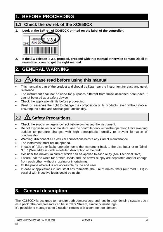
1. BEFORE PROCEEDING 1.1 Check the sw rel. of the XC650CX 1. Look at the SW rel. of XC650CX printed on the label of the controller.
2. If the SW release is 3.4, proceed, proceed with this manual otherwise contact Dixell at
www.dixell.com to get the right manual.
2. GENERAL WARNING
2.1 Please read before using this manual This manual is part of the product and should be kept near the instrument for easy and quick
reference. The instrument shall not be used for purposes different from those described hereunder. It
cannot be used as a safety device. Check the application limits before proceeding. Dixell Srl reserves the right to change the composition of its products, even without notice,
ensuring the same and unchanged functionality.
2.2 Safety Precautions Check the supply voltage is correct before connecting the instrument. Do not expose to water or moisture: use the controller only within the operating limits avoiding
sudden temperature changes with high atmospheric humidity to prevent formation of condensation
Warning: disconnect all electrical connections before any kind of maintenance. The instrument must not be opened. In case of failure or faulty operation send the instrument back to the distributor or to “Dixell
S.r.l.” (See address) with a detailed description of the fault. Consider the maximum current which can be applied to each relay (see Technical Data). Ensure that the wires for probes, loads and the power supply are separated and far enough
from each other, without crossing or intertwining. Fit the probe where it is not accessible by the end user. In case of applications in industrial environments, the use of mains filters (our mod. FT1) in
parallel with inductive loads could be useful.
3. General description The XC650CX is designed to manage both compressors and fans in a condensing system such as a pack. The compressors can be scroll or Stream, simple or multistage. It’s possible to manage up to 2 suction circuits with a common condenser.
1592001430 XC650CX GB r3.4 11.12.2018 XC650CX 6/54
Control is by means of a neutral zone and is based on the pressure or temperature sensed in the LP suction (compressors) and HP (condenser) circuits. A special algorithm balances the run hours of the compressors to distribute the work load uniformly. The controllers can convert both LP and HP pressures and displays them as temperatures. The front panel offers complete information on the system’s status by displaying the suction and condenser pressure (temperatures), the status of the loads, possible alarms or maintenance conditions. Each load has its own alarm input that is able to stop it when activated. By means of the HOT KEY the controller can be easy programmed at power on. The controller can be connected to the X-WEB, controlling and monitoring system, thanks to the RS485 serial output, using the standard ModBus RTU protocol.
4. COMPONENTS RELATED TO THE XC650CX
Name Description Part number
Transformer TF5 230V/12Vac CD050010 00
Wiring kit 1.5m and 3m CW15-Kit (1.5m) CW25-Kit (2.5m)
DD500001 50 DD500002 50
Female disconnect able connector for digital input or analog output (4pcs)
CABCJ15 (1,5m) CABCJ30 (3,0m)
DD200101 50 DD200103 00
TTL /RS485 serial converter XJ485CX+CABRS02 J7MAZZZ9AA
4-20mA suction pressure transducer PP11 (-0.5÷11bar) BE009302 07
4-20mA condenser pressure transducer PP30 (0÷30bar) BE009302 04
Hot key for programming HOT KEY 4K DK00000100
1592001430 XC650CX GB r3.4 11.12.2018 XC650CX 7/54
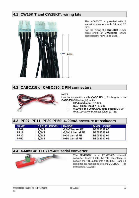
4.1 CW15KIT and CW25KIT: wiring kits
The XC650CX is provided with 2 socket connectors with 14 and 12 pins. For the wiring the CW15KIT (1.5m cable length) or CWC25KIT (2.5m cable length) have to be used.
4.2 CABCJ15 or CABCJ30: 2 PIN connectors
NOTE: Use the connection cable CABCJ15 (1.5m lenght) or the CABCJ30 (3.0m lenght) for the:
- HP digital input (31-32), - D.I.7 digital input 7 (33-34), - 0-10Vdc or 4-20mA analogue output (29-30) - oA6, 12Vdc/40mA digital output (27-28)
4.3 PP07, PP11, PP30 PP50: 4÷20mA pressure transducers NAME CABLE LENGTH RANGE DIXELL CODE PP07 2,0MT -0,5+7 bar rel FE BE009302 00 PP11 2,0MT -0,5+11 bar rel FE BE009302 07 PP30 2,0MT 0+30 bar rel FE BE009302 04 PP50 2,0MT 0+50 bar rel FE BE009302 05
4.4 XJ485CX: TTL / RS485 serial converter
The XJ485CX is a TTL/RS485 external converter. Insert it into the TTL receptacle to convert the TTL output into a RS485 (+) and (-) signal for the monitoring system MODBUS_RTU compatible. (XWEB).
1592001430 XC650CX GB r3.4 11.12.2018 XC650CX 8/54
5. WIRING & ELECTRICAL CONNECTIONS
5.1 General warnings Before connecting cables make sure the power supply complies with the instrument’s requirements. Separate the probe cables from the power supply cables, from the outputs and the power connections. Do not exceed the maximum current allowed on each relay 5A resistive, in case of heavier loads use a suitable external relay.
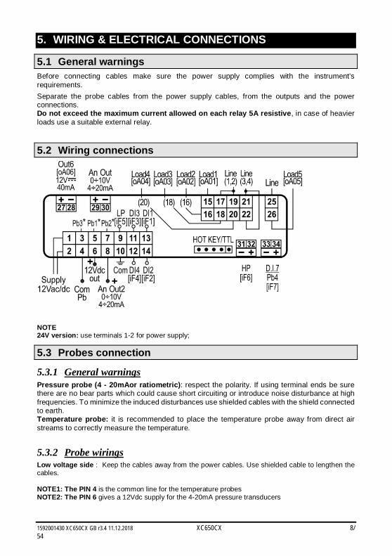
5.2 Wiring connections
NOTE 24V version: use terminals 1-2 for power supply;
5.3 Probes connection
5.3.1 General warnings Pressure probe (4 - 20mAor ratiometric): respect the polarity. If using terminal ends be sure there are no bear parts which could cause short circuiting or introduce noise disturbance at high frequencies. To minimize the induced disturbances use shielded cables with the shield connected to earth. Temperature probe: it is recommended to place the temperature probe away from direct air streams to correctly measure the temperature.
5.3.2 Probe wirings Low voltage side : Keep the cables away from the power cables. Use shielded cable to lengthen the cables. NOTE1: The PIN 4 is the common line for the temperature probes NOTE2: The PIN 6 gives a 12Vdc supply for the 4-20mA pressure transducers
1592001430 XC650CX GB r3.4 11.12.2018 XC650CX 9/54
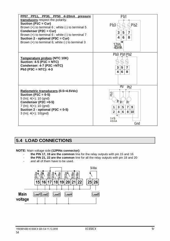
PP07 PP11, PP30, PP50 4÷20mA pressure transducers respect the polarity. Suction (P1C = Cur) Brown (+) to terminal 6 ; white (-) to terminal 5 Condenser (P2C = Cur) Brown (+) to terminal 6 ; white (-) to terminal 7 Suction 2 - optional (P3C = Cur) Brown (+) to terminal 6; white (-) to terminal 3
3 5 74 6 8
12V40mA
§
Pb1
Pb3 Pb2
Temperature probes (NTC 10K) Suction: 4-5 (P1C = NTC) Condenser: 4-7 (P2C =NTC) Pb3 (P3C = NTC): 4-3 3 5 7
4 6 8
Pb1Pb3 Pb2
Ratiometric transducers (0.5÷4.5Vdc) Suction (P1C = 0-5) 5 (In); 4(+); 10 (gnd) Condenser (P2C =0-5) 7 (In); 4(+); 10 (gnd) Suction 2 - optional (P3C = 0-5) 3 (In); 4(+); 10(gnd)
5 V4 0 m A
§
1 3 5 7 92 4 6 8 10
+
In
Pb1 Pb2
In
Gnd
In
Pb3
5.4 LOAD CONNECTIONS NOTE: Main voltage side (12PINs connector):
- the PIN 17, 19 are the common line for the relay outputs with pin 15 and 16 - the PIN 21, 22 are the common line for all the relay outputs with pin 18 and 20 - and all of them have to be used.
1592001430 XC650CX GB r3.4 11.12.2018 XC650CX 10/54
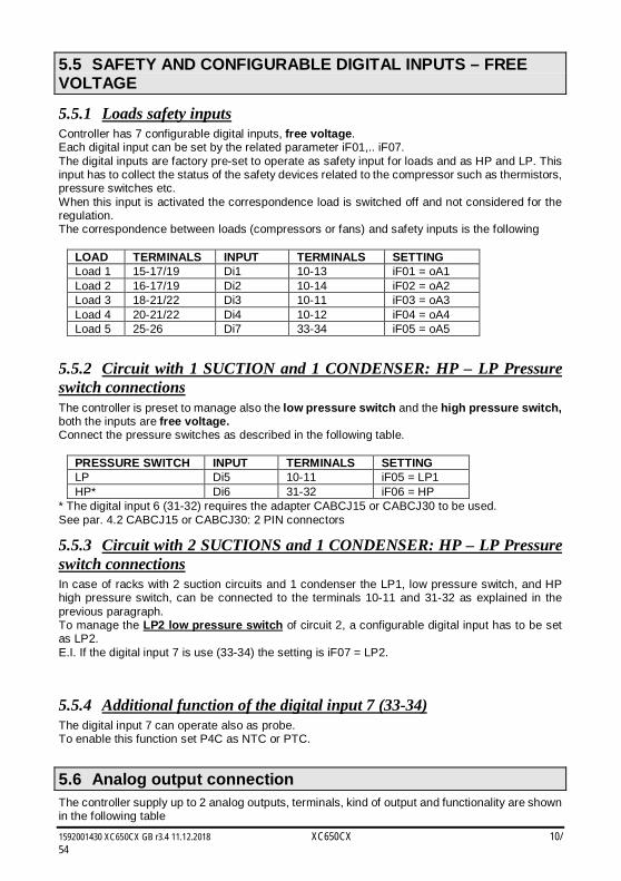
5.5 SAFETY AND CONFIGURABLE DIGITAL INPUTS – FREE VOLTAGE
5.5.1 Loads safety inputs Controller has 7 configurable digital inputs, free voltage. Each digital input can be set by the related parameter iF01,.. iF07. The digital inputs are factory pre-set to operate as safety input for loads and as HP and LP. This input has to collect the status of the safety devices related to the compressor such as thermistors, pressure switches etc. When this input is activated the correspondence load is switched off and not considered for the regulation. The correspondence between loads (compressors or fans) and safety inputs is the following
LOAD TERMINALS INPUT TERMINALS SETTING Load 1 15-17/19 Di1 10-13 iF01 = oA1 Load 2 16-17/19 Di2 10-14 iF02 = oA2 Load 3 18-21/22 Di3 10-11 iF03 = oA3 Load 4 20-21/22 Di4 10-12 iF04 = oA4 Load 5 25-26 Di7 33-34 iF05 = oA5
5.5.2 Circuit with 1 SUCTION and 1 CONDENSER: HP – LP Pressure switch connections The controller is preset to manage also the low pressure switch and the high pressure switch, both the inputs are free voltage. Connect the pressure switches as described in the following table.
PRESSURE SWITCH INPUT TERMINALS SETTING LP Di5 10-11 iF05 = LP1 HP* Di6 31-32 iF06 = HP
* The digital input 6 (31-32) requires the adapter CABCJ15 or CABCJ30 to be used. See par. 4.2 CABCJ15 or CABCJ30: 2 PIN connectors
5.5.3 Circuit with 2 SUCTIONS and 1 CONDENSER: HP – LP Pressure switch connections In case of racks with 2 suction circuits and 1 condenser the LP1, low pressure switch, and HP high pressure switch, can be connected to the terminals 10-11 and 31-32 as explained in the previous paragraph. To manage the LP2 low pressure switch of circuit 2, a configurable digital input has to be set as LP2. E.I. If the digital input 7 is use (33-34) the setting is iF07 = LP2.
5.5.4 Additional function of the digital input 7 (33-34) The digital input 7 can operate also as probe. To enable this function set P4C as NTC or PTC.
5.6 Analog output connection The controller supply up to 2 analog outputs, terminals, kind of output and functionality are shown in the following table
1592001430 XC650CX GB r3.4 11.12.2018 XC650CX 11/54
Terminals Related parameter Analog output 1 29[+] – 30[-]. AOC: Kind of signal (4-20mA/0-10V)
AOF: function Analog output 2 8[+] – 10[-]. 2AOC: Kind of signal (4-20mA/0-10V)
2AOF: function
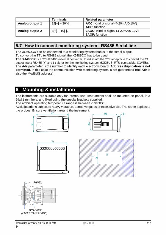
5.7 How to connect monitoring system - RS485 Serial line The XC650CX can be connected to a monitoring system thanks to the serial output. To convert the TTL to RS485 signal, the XJ485CX has to be used. The XJ485CX is a TTL/RS485 external converter. Insert it into the TTL receptacle to convert the TTL output into a RS485 (+) and (-) signal for the monitoring system MODBUS_RTU compatible. (XWEB). The Adr parameter is the number to identify each electronic board. Address duplication is not permitted, in this case the communication with monitoring system is not guaranteed (the Adr is also the ModBUS address). 6. Mounting & installation The instruments are suitable only for internal use. Instruments shall be mounted on panel, in a 29x71 mm hole, and fixed using the special brackets supplied. The ambient operating temperature range is between -10÷60°C. Avoid locations subject to heavy vibration, corrosive gases or excessive dirt. The same applies to the probes. Ensure ventilation around the instrument.
78,5
36,9
59,5
28,5
6
70
29
71
1592001430 XC650CX GB r3.4 11.12.2018 XC650CX 12/54
7. First installation At first installation, it’s necessary the following: 1. Select the kind of gas. 2. Set the range of the pressure probes. In the following paragraph a short cut for the above operations. Chapters 11 Parameters programming and 0 will show in detail these operations.
7.1 How to set the kind of gas The kind of gas is set by the parameter FtyP. The controller has memorized the relation between temperature and pressure for some gases. The pre-set gas is: r404. (FtyP=r404) If another gas is used, act as in the following: 1. Enter the Programming mode by pressing the Set and DOWN key for 3s. 2. Select the “Pr2” parameter. Then enter the password 3 2 1 0. 3. Select the FtyP, kind of gas, parameter. 4. Press the “SET” key: the value of the parameter will start blinking. 5. Use “UP” or “DOWN” to change the gas among the following: r22= R22; r134=134,
r404=R404A; - 407A = r407A; 407C= r407C; 407F= r407F; 410= r410; 507=R507; CO2= CO2; r32 = r32; r290 = r290; r448 = r448A; r449 = r449A, r450 = r450A, r513= r513; 1234 = r1234ze
6. Press “SET” to store the new value and move to the following parameter. To exit: Press SET + UP or wait 30s without pressing a key. NOTE: the set value is stored even when the procedure is exited by waiting the time-out to expire.
7.2 How to set the range of the pressure probes If an instrument with the following part number is used: XC650CX – xxxxF, it is pre-set to work with pressure probe with the following range: Suction Probe : -0.5 ÷11.0 bar (relative pressure); Discharge Probe : 0÷30.0 bar (relative pressure) If the probes you’re using have a different range act as in the following: To set the pressure range of the Probe 1 (suction probe) use the parameter: PA04: Adjustment of read out corresponding to 4mA (0.5V) PA20: Adjustment of read out corresponding to 20mA (4.5V) To set the pressure range of the Probe 2 (Condenser probe) use the parameter: FA04: Adjustment of read out corresponding to 4mA (0.5V) FA20: Adjustment of read out corresponding to 20mA (4.5V) Practically these parameters have to be set with the start and end scale of the probe range. How to do: 1. Enter the Programming mode by pressing the Set and DOWN key for 3s. 2. Select the “Pr2” parameter. Then enter the password 3 2 1 0.
1592001430 XC650CX GB r3.4 11.12.2018 XC650CX 13/54
3. Select the PA04, adjustment of read out corresponding to 4mA (0.5V), parameter. 4. Press the “SET” key: the value of the parameter will start blinking. 5. Set the lower value of the probe range. 6. Push the SET key to confirm the value. The PA20: adjustment of read out corresponding
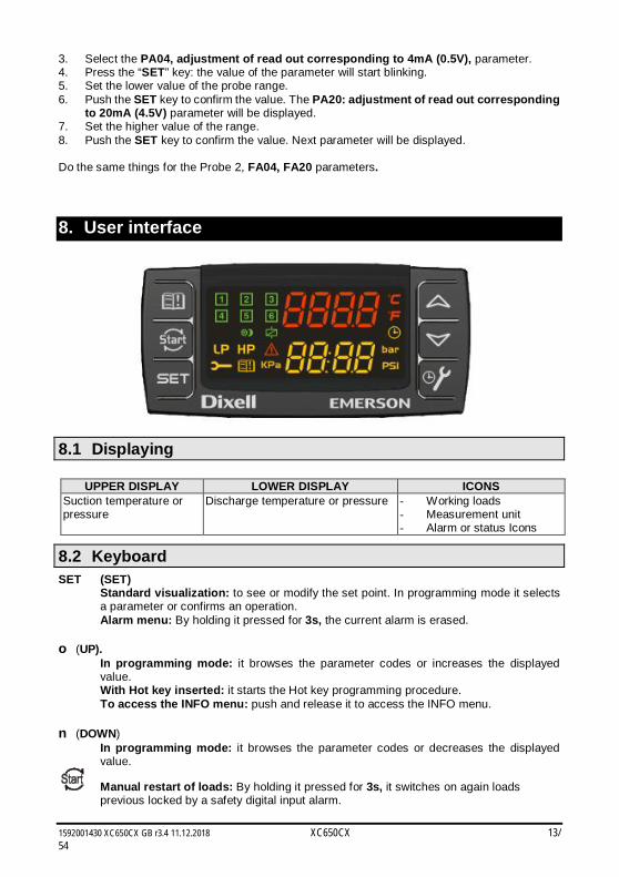
to 20mA (4.5V) parameter will be displayed. 7. Set the higher value of the range. 8. Push the SET key to confirm the value. Next parameter will be displayed. Do the same things for the Probe 2, FA04, FA20 parameters. 8. User interface
8.1 Displaying
UPPER DISPLAY LOWER DISPLAY ICONS Suction temperature or pressure
Discharge temperature or pressure - Working loads - Measurement unit - Alarm or status Icons
8.2 Keyboard SET (SET)
Standard visualization: to see or modify the set point. In programming mode it selects a parameter or confirms an operation.
Alarm menu: By holding it pressed for 3s, the current alarm is erased. o (UP).
In programming mode: it browses the parameter codes or increases the displayed value. With Hot key inserted: it starts the Hot key programming procedure. To access the INFO menu: push and release it to access the INFO menu.
n (DOWN)
In programming mode: it browses the parameter codes or decreases the displayed value.
Manual restart of loads: By holding it pressed for 3s, it switches on again loads previous locked by a safety digital input alarm.
1592001430 XC650CX GB r3.4 11.12.2018 XC650CX 14/54
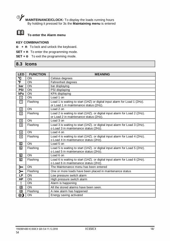
MAINTEINANCE/CLOCK: To display the loads running hours By holding it pressed for 3s the Maintaining menu is entered
To enter the Alarm menu KEY COMBINATIONS o + nTo lock and unlock the keyboard. SET + n To enter the programming mode. SET + o To exit the programming mode.
8.3 Icons LED FUNCTION MEANING
ON Celsius degrees ON Fahrenheit degrees
bar ON bar displaying PSI ON PSI displaying kPa ON KPA displaying
ON Load 1 on
Flashing Load 1 is waiting to start (1HZ) or digital input alarm for Load 1 (2Hz). or Load 1 in maintenance status (2Hz).
ON Load 2 on
Flashing Load 2 is waiting to start (1HZ). or digital input alarm for Load 2 (2Hz). or Load 2 in maintenance status (2Hz).
ON Load 3 on
Flashing Load 3 is waiting to start (1HZ). or digital input alarm for Load 3 (2Hz). o Load 3 in maintenance status (2Hz).
ON Load 4 on
Flashing Load 4 is waiting to start (1HZ). or digital input alarm for Load 4 (2Hz). o Load 4 in maintenance status (2Hz).
5 ON Load 5 on 5 Flashing Load 5 is waiting to start (1HZ). or digital input alarm for Load 5 (2Hz).
o Load 5 in maintenance status (2Hz). 6 ON Load 6 on 6 Flashing Load 6 is waiting to start (1HZ). or digital input alarm for Load 6 (2Hz).
o Load 6 in maintenance status (2Hz). ON The Maintenance menu has been entered
Flashing One or more loads have been placed in maintenance status LP ON Low pressure switch alarm HP ON High pressure switch alarm
ON Alarm is happening
ON All the stored alarms have been seen. Flashing A new alarm has happened ON Energy saving activated
1592001430 XC650CX GB r3.4 11.12.2018 XC650CX 15/54
9. How to see and modify the set point(s)
9.1 How to see the set point of compressors and/or fans If the controller is managing both compressors and fans, both the set points are displayed in sequence, otherwise only the set point of the enabled section will be displayed. 1) Push and release the SET key; 2) The Lower display will show the “SEtC” label, while the Upper display will show its value. 3) If second suction is configured, by pushing again the SET key the Lower display will show
the “StC2” label, while the Upper display will show its value 4) To see the fan set point, push again the SET key. 5) The Lower display will show the “SEtF” label, while the Upper display will show the fan set
point. To exit: push the SET key or wait for 30 without pressing any keys.
9.2 How to modify the set point of compressors and/or fans ******WARNING: before setting the target set points for the first time, check and, if necessary, modify the type of refrigerant gas (par. FtyP) and the default unit of measurement (par. dEU) for compressors and fans ********** PRE-ACTION 1. Set the kind of refrigerant by means of the FtyP parameter (see 7.1 How to set the kind
of gas) 2. Set the measurement unit (dEU par.). 3. Check and if necessary modify the set point limits (LSE and HSE par.). PROCEDURE 1. Push the SET key for more than 2 seconds; 2. The Lower display will show the “SEtC1” label, will the Upper display will show its value
flashing. 3. To change the suction set point value, push the o or n within 30s. 4. To memorize the new value and pass to the fan set point, push the SET key. 5. If the second circuit is enabled the Lower display will show the “SEtC2” label, will the Upper
display will show its value flashing. 6. To change the suction set point value, push the o or n within 30s. 7. To memorize the new value and pass to the fan set point, push the SET key. 8. The Lower display will show the “SEtF” label, will the Upper display will show the fan set
point flashing. 9. To change its value, push the o or n within 30s. To exit: push the SET key or wait for 30 without pressing any keys.
10. The INFO menu The controller can display some information directly from the main menu. The INFO menu is accessible by pushing and releasing the UP key: Here below the list of the information that can be displayed: NOTE: this information is displayed only if the related function is enabled
P1t: temperature value of the P1 probe P1P: pressure value of the P1 probe
1592001430 XC650CX GB r3.4 11.12.2018 XC650CX 16/54
P2t: temperature value of the P2 probe P2P: pressure value of the P2 probe (if P2 present) P3t: temperature value of the P3 probe (if P3 present) P3P: pressure value of the P3 probe (if P3 present) P4t: temperature value of the P4 probe (if P4 present) LInJ: status of the injection output (“On” – “OFF”), This information is available
only if one relay, oA2 ÷oA4 is set as “Lin”. SEtd: value of the Dynamic Set point.
This information is available only if the Dynamic set point function is enabled (par. dSEP ≠ nP)
AO1 Percentage of the analog output 1 (4-20mA or 0-10V). This information is always available AO2: Percentage of the analog output 2 (4-20mA or 0-10V). This information is always available SSC1: Supervising Set for circuit 1, if supervising system is sending the set point
to the controller SSC2: Supervising Set for circuit 2, if supervising system is sending the set point
to the controller SStF: Supervising Set for fan, if supervising system is sending the set point to
the controller SH: Superheat
EXIT: push the SET+UP keys together.
11. Parameters programming
11.1 How to enter the “Pr1” parameter list To enter the “Pr1” parameter list, user accessible, operate as follows: 1. Hold pressed the SET and DOWN key for 3s. 2. The controller displays the name of the parameter in the Lower display, its value on the Upper
display. 3. Press the “SET” key: the value of the parameter will start blinking. 4. Use “UP” or “DOWN” to change the value. 5. Press “SET” to store the new value and move to the following parameter. To exit: Press SET + UP or wait 30s without pressing a key. NOTE: the set value is stored even when the procedure is exited by waiting the time-out to expire.
11.2 How to enter in parameters list “Pr2” The “Pr2” parameter list is protected by a security code (Password).
SECURITY CODE is 3210
To access parameters in “Pr2”: 1. Enter the “Pr1” level. 2. Select “Pr2” parameter and press the “SET” key. 3. The flashing value “0 ---” is displayed. 4. Use o or n to input the security code and confirm the figure by pressing “SET” key.
1592001430 XC650CX GB r3.4 11.12.2018 XC650CX 17/54
5. Repeat operations 2 and 3 for the other digits. NOTE: each parameter in “Pr2” can be removed or put into “Pr1” (user level) by pressing “SET” + n. When a parameter is present also in “Pr1” decimal point of the lower display is on.
11.3 How to change parameter values 1. Enter the Programming mode. 2. Select the required parameter with o or n. 3. Press the “SET” key the value start blinking. 4. Use o or n to change its value. 5. Press “SET” to store the new value and move to the following parameter. To exit: Press SET + UP or wait 15s without pressing a key. NOTE: the new programming is stored even when the procedure is exited by waiting the time-out.
12. How to disabled an output To disabled an output during a maintenance session means to exclude the output from the regulation.
12.1 How to disabled an output during a maintenance session. 1. Push the MAINTENANCE/CLOCK ( ) key for 3s. 2. The LED’s of the first output is switched on, the Lower display shows the “StA” label, while
the Upper display shows the “On” label if the first output is enabled, or the “oFF” label if the output is disabled for a maintenance section. With compressor with more steps all the LED’s linked to the compressor and the valves are switched on..
3. Select the output by pressing the UP or DOWN key. 4. To modify the status of the output: push the SET key, the status of the output starts
flashing, then push the UP or DOWN to pass from “On” to “OFF” and vice versa. 5. Push the SET key to confirm the status and pass to the next output.. To exit: push the CLOCK key or wait 30 sec
12.2 Output disabled signaling. If an output is disabled its led blinks (2 Hz)
12.3 Regulation with some outputs disabled. If some outputs are disabled they don’t take part to the regulation, so the regulation goes on with the other outputs.
13. Running hours of loads
13.1 How to display the running hours of a load. The controller memorizes the running hours of each load. To see how long a load has been working follow this procedure:
1592001430 XC650CX GB r3.4 11.12.2018 XC650CX 18/54
1. Press and release the “MAINTENANCE/CLOCK ( )” key. 2. The LED of the first output is switched on, the Upper Display shows the “HUr” label, while
the Lower Display shows the shows the running hours of the first output. 3. To see the running hours of the following load press the UP key . To exit: push the key or wait 30 sec
13.2 How to reset the running hours of a load. 1. Display the running hour according to the above procedure. 2. Select the load by pressing the UP key. 3. Push the SET key (immediately on the lower display the rSt label is displayed). 4. Hold pushed the key for some seconds till the “rSt” label starts flashing and the lower display
shows zero. To exit: push the CLOCK key or wait 30 sec NOTE: if the SET key is released within 2s, the controller reverts to display the running hours of the selected loads..
14. Alarm Menu The controller memorizes the last 20 alarms happened, together with their duration.. To see the alarm codes see par. par. 23.
14.1 How to see the alarms
1. Push the Alarm key. 2. The last alarm happened is showed on the Upper display, while the lower display shows its
number. 3. Push again the o key and the other alarm are displayed starting from the most recent. 4. To see the alarm duration and push the SET key. 5. By pushing again the o or SET key the next alarm is displayed. Alarms erasing. 1. Enter the Alarm Menu. 2. To erase the displayed alarm push the “SET” key till the “rSt” label will be displayed in the
Lower Display, NOTE the running alarms cannot be erased.. 3. To erase the whole Alarm Menu, hold pressed the “SET” key for 10s.
15. Keyboard locking
15.1 How to lock the keyboard 1. Keep the o and n keys pressed together for more than 3 s the o and n keys. 2. The “POF” message will be displayed and the keyboard is locked. At this point it is only
possible to view the set point or enter the HACCP menu.
1592001430 XC650CX GB r3.4 11.12.2018 XC650CX 19/54
15.2 To unlock the keyboard Keep the o and n keys pressed together for more than 3s till the “POn” flashing message appears.
16. Use of the programming “HOT KEY “
16.1 How to program a hot key from the instrument (UPLOAD) 1. Program one controller with the front keypad. 2. When the controller is ON, insert the “Hot key” and push o key; the "uPL" message
appears followed a by flashing “End” 3. Push “SET” key and the End will stop flashing. 4. Turn OFF the instrument remove the “Hot Key”, then turn it ON again. NOTE: the “Err” message is displayed for failed programming. In this case push again o key if you want to restart the upload again or remove the “Hot key” to abort the operation.
16.2 How to program an instrument using a hot key (DOWNLOAD) 1. Turn OFF the instrument. 2. Insert a programmed “Hot Key” into the 5 PIN receptacle and then turn the Controller
ON. 3. Automatically the parameter list of the “Hot Key” is downloaded into the Controller memory,
the “doL” message is blinking followed a by flashing “End”. 4. After 10 seconds the instrument will restart working with the new parameters. 5. Remove the “Hot Key”.. NOTE the message “Err” is displayed for failed programming. In this case turn the unit off and then on if you want to restart the download again or remove the “Hot key” to abort the operation. The unit can UPLOAD or DOWNLOAD the parameter list from its own E2 internal memory to the “Hot Key” and vice-versa. 17. List of parameters
17.1 Plant dimensioning and type of regulation. The XC650CX is pre-set to drive a rack with 3 compressors and 2 fans. oA1 (term. 15-17/19), oA2 (term. 16-17/19), oA3 (term. 18-21/22), oA4 (term. 20-21/22), oA5 (term. 25/26), relay 1, 2, 3, 4, 5 configuration, oA6 (term. 27-28) 12Vdc/40mA output 6 configuration: by means of these parameters the plant can be dimensioned according to the number and type of compressors and/or fans and the number of steps for each one. Each relay according to the configuration of the oA(i), where (i) = 1, 2, 3, 4, 5, 6 parameter can work as: - Not used: oA(i) = nu - Compressor circuit1: oA(i) = cPr1, - Compressor circuit2: oA(i) = cPr2, - Step: oA(i) i = StP - Inverter compressor for circuit 1: oA(i) = inC1 - Inverter compressor for circuit 2: oA(i) = inC2
1592001430 XC650CX GB r3.4 11.12.2018 XC650CX 20/54
- Fan: oA(i) = FAn - Fan with inverter/ECI fan: oA(i) = InF - Injection of cooling liquid: oA(i) = Lin - Alarm: oA(i) = ALr - Flood protection function: oA(i) = Liq - Valve for hot gas injection in case of low superheat: oA(i) = HGi
NOTE: also the “dGS”, “6dG”, “dGst” values are present. These values must not be used.
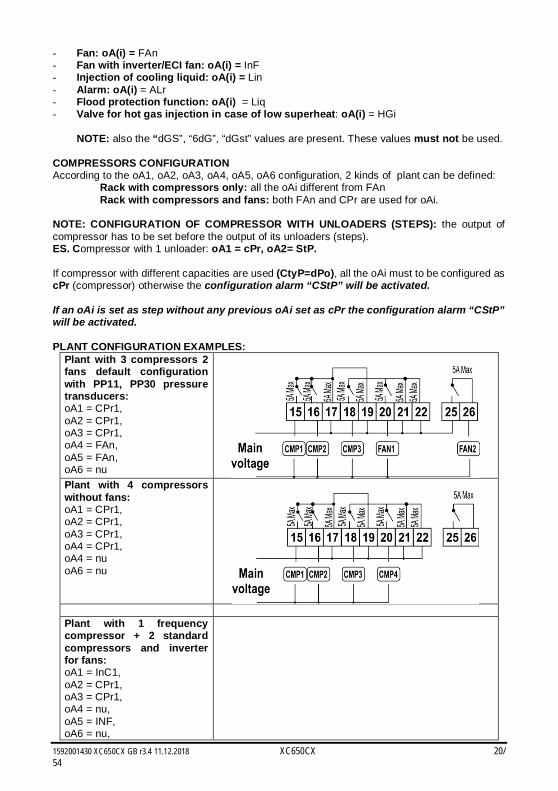
COMPRESSORS CONFIGURATION According to the oA1, oA2, oA3, oA4, oA5, oA6 configuration, 2 kinds of plant can be defined: Rack with compressors only: all the oAi different from FAn Rack with compressors and fans: both FAn and CPr are used for oAi. NOTE: CONFIGURATION OF COMPRESSOR WITH UNLOADERS (STEPS): the output of compressor has to be set before the output of its unloaders (steps). ES. Compressor with 1 unloader: oA1 = cPr, oA2= StP. If compressor with different capacities are used (CtyP=dPo), all the oAi must to be configured as cPr (compressor) otherwise the configuration alarm “CStP” will be activated. If an oAi is set as step without any previous oAi set as cPr the configuration alarm “CStP” will be activated. PLANT CONFIGURATION EXAMPLES:
Plant with 3 compressors 2 fans default configuration with PP11, PP30 pressure transducers: oA1 = CPr1, oA2 = CPr1, oA3 = CPr1, oA4 = FAn, oA5 = FAn, oA6 = nu
Plant with 4 compressors without fans: oA1 = CPr1, oA2 = CPr1, oA3 = CPr1, oA4 = CPr1, oA4 = nu oA6 = nu
Plant with 1 frequency compressor + 2 standard compressors and inverter for fans: oA1 = InC1, oA2 = CPr1, oA3 = CPr1, oA4 = nu, oA5 = INF, oA6 = nu,
1592001430 XC650CX GB r3.4 11.12.2018 XC650CX 21/54
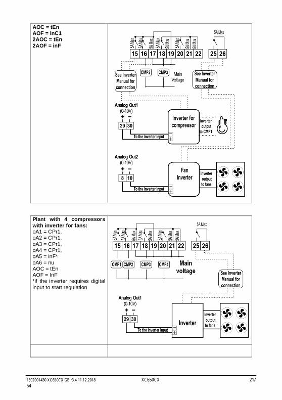
AOC = tEn AOF = InC1 2AOC = tEn 2AOF = inF
Plant with 4 compressors with inverter for fans: oA1 = CPr1, oA2 = CPr1, oA3 = CPr1, oA4 = CPr1, oA5 = inF* oA6 = nu AOC = tEn AOF = InF *if the inverter requires digital input to start regulation
1592001430 XC650CX GB r3.4 11.12.2018 XC650CX 22/54
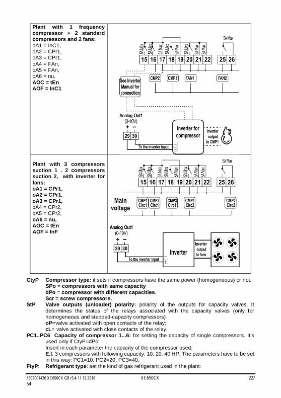
Plant with 1 frequency compressor + 2 standard compressors and 2 fans: oA1 = InC1, oA2 = CPr1, oA3 = CPr1, oA4 = FAn, oA5 = FAn, oA6 = nu, AOC = tEn AOF = InC1
Plant with 3 compressors suction 1 , 2 compressors suction 2, with inverter for fans: oA1 = CPr1, oA2 = CPr1, oA3 = CPr1, oA4 = CPr2, oA5 = CPr2, oA6 = nu, AOC = tEn AOF = InF
CtyP Compressor type: it sets if compressors have the same power (homogeneous) or not. SPo = compressors with same capacity dPo = compressor with different capacities. Scr = screw compressors. StP Valve outputs (unloader) polarity: polarity of the outputs for capacity valves. It
determines the status of the relays associated with the capacity valves (only for homogeneous and stepped-capacity compressors) oP=valve activated with open contacts of the relay; cL= valve activated with close contacts of the relay.
PC1..PC6 Capacity of compressor 1...6: for setting the capacity of single compressors. It’s used only if CtyP=dPo. Insert in each parameter the capacity of the compressor used. E.I. 3 compressors with following capacity: 10, 20, 40 HP. The parameters have to be set in this way: PC1=10, PC2=20, PC3=40.
FtyP: Refrigerant type: set the kind of gas refrigerant used in the plant:
1592001430 XC650CX GB r3.4 11.12.2018 XC650CX 23/54
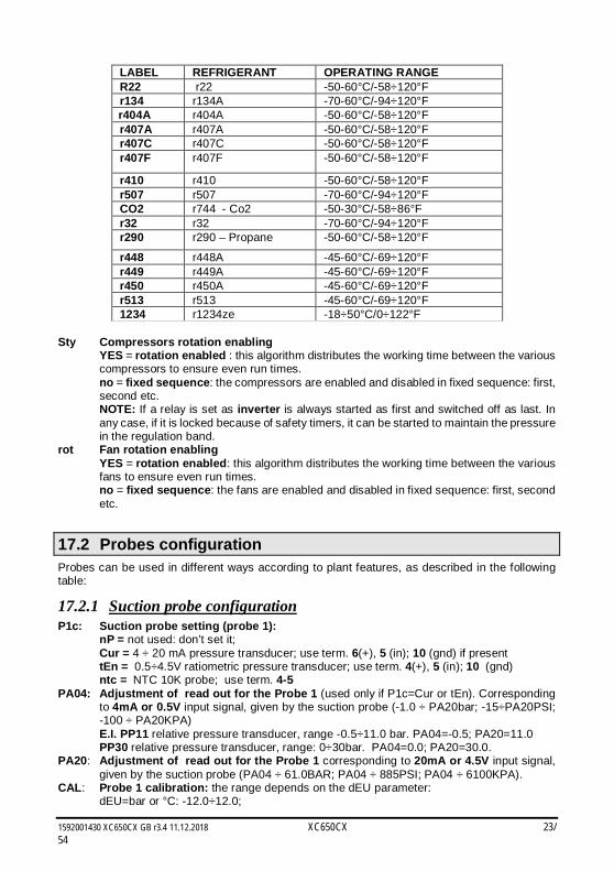
LABEL REFRIGERANT OPERATING RANGE R22 r22 -50-60°C/-58÷120°F r134 r134A -70-60°C/-94÷120°F r404A r404A -50-60°C/-58÷120°F r407A r407A -50-60°C/-58÷120°F r407C r407C -50-60°C/-58÷120°F r407F r407F -50-60°C/-58÷120°F
r410 r410 -50-60°C/-58÷120°F r507 r507 -70-60°C/-94÷120°F CO2 r744 - Co2 -50-30°C/-58÷86°F r32 r32 -70-60°C/-94÷120°F r290 r290 – Propane -50-60°C/-58÷120°F r448 r448A -45-60°C/-69÷120°F r449 r449A -45-60°C/-69÷120°F r450 r450A -45-60°C/-69÷120°F r513 r513 -45-60°C/-69÷120°F 1234 r1234ze -18÷50°C/0÷122°F
Sty Compressors rotation enabling YES = rotation enabled : this algorithm distributes the working time between the various
compressors to ensure even run times. no = fixed sequence: the compressors are enabled and disabled in fixed sequence: first,
second etc. NOTE: If a relay is set as inverter is always started as first and switched off as last. In
any case, if it is locked because of safety timers, it can be started to maintain the pressure in the regulation band.
rot Fan rotation enabling YES = rotation enabled: this algorithm distributes the working time between the various
fans to ensure even run times. no = fixed sequence: the fans are enabled and disabled in fixed sequence: first, second
etc.
17.2 Probes configuration Probes can be used in different ways according to plant features, as described in the following table:
17.2.1 Suction probe configuration P1c: Suction probe setting (probe 1):
nP = not used: don’t set it; Cur = 4 ÷ 20 mA pressure transducer; use term. 6(+), 5 (in); 10 (gnd) if present tEn = 0.5÷4.5V ratiometric pressure transducer; use term. 4(+), 5 (in); 10 (gnd) ntc = NTC 10K probe; use term. 4-5
PA04: Adjustment of read out for the Probe 1 (used only if P1c=Cur or tEn). Corresponding to 4mA or 0.5V input signal, given by the suction probe (-1.0 ÷ PA20bar; -15÷PA20PSI; -100 ÷ PA20KPA)
E.I. PP11 relative pressure transducer, range -0.5÷11.0 bar. PA04=-0.5; PA20=11.0 PP30 relative pressure transducer, range: 0÷30bar. PA04=0.0; PA20=30.0. PA20: Adjustment of read out for the Probe 1 corresponding to 20mA or 4.5V input signal,
given by the suction probe (PA04 ÷ 61.0BAR; PA04 ÷ 885PSI; PA04 ÷ 6100KPA). CAL: Probe 1 calibration: the range depends on the dEU parameter:
dEU=bar or °C: -12.0÷12.0;
1592001430 XC650CX GB r3.4 11.12.2018 XC650CX 24/54
dEU=PSI or °F: -200÷200; dEU=kPA: -999÷999;
17.2.2 Condenser probe configuration P2c: Condenser probe setting (probe 2):
nP = not used: Cur = 4 ÷ 20 mA pressure transducer; use term. 6(+), 7 (in); 10 (gnd) if present tEn = 0.5÷4.5V ratiometric pressure transducer; use term. . 4(+), 7 (in); 10 (gnd ntc = NTC 10K probe; use term. 4-7
FA04: Adjustment of read out for the Probe 2 (used only if P2c=Cur or tEn). corresponding to 4mA or 0.5V input signal, given by the delivery probe (-1.0 ÷ FA20bar; -15÷FA20PSI; -100 ÷ FA20KPA)
FA20: Adjustment of read out for the Probe 2 corresponding to 20mA or 4.5V input signal, given by the condensing probe (FA04 ÷ 61.0BAR; FA04 ÷ 885PSI; FA04 ÷ 6100KPA)
FCAL: Probe 2 calibration the range depends on the dEU parameter: dEU=bar or °C: -12.0÷12.0; dEU=PSI or °F: -200÷200; dEU=kPA: -999÷999;
17.2.3 Probe 3 configuration P3c: Probe 3 setting:
nP = not used: Cur = 4 ÷ 20 mA pressure transducer; use term. 6(+), 3 (in); 10 (gnd) if present tEn = 0.5÷4.5V ratiometric pressure transducer; use term. . 4(+), 3 (in); 10 (gnd nt10 = NTC 10K probe; use term. 3-4 nt86 = NTC 86K use term. 3-4
3P04: Adjustment of read out for the Probe 3 (used only if P3c=Cur or tEn). corresponding to 4mA or 0.5V input signal, given by the delivery probe (-1.0 ÷ 3P20bar; -15÷3P20 PSI; -100 ÷ 3P20 KPA)
3P20: Adjustment of read out for the Probe 3 corresponding to 20mA or 4.5V input signal, given by the condensing probe (3P04 ÷ 61.0BAR; 3P04 ÷ 885PSI; 3P04 ÷ 6100KPA)
O3: Probe 3 calibration the range depends on the dEU parameter: dEU=bar or °C: -12.0÷12.0; dEU=PSI or °F: -200÷200; dEU=kPA: -999÷999;
17.2.4 Probe 4 configuration P4c: Probe 4 setting (33-34):
nP = not used: nt10 = NTC 10K nt86 = NTC 86K
O4: Probe 4 calibration the range depends on the dEU parameter: dEU= °C: -12.0÷12.0; dEU= °F: -200÷200;
17.2.5 Probe selection second suction circuit 2CPb: Probe selection for second suction circuit
nP = not used: P1 = Probe 1 – NOT SET IT: already used for first suction circuit P2 = Probe 2 – NOT SET IT : already used for fan P3 = Probe 3 – SET this probe!
17.2.6 Probe selection for fan FPb: Probe selection for condenser fan
nP = not used:
1592001430 XC650CX GB r3.4 11.12.2018 XC650CX 25/54
P1 = Probe 1 P2 = Probe 2 – Factory setting P3 = Probe 3
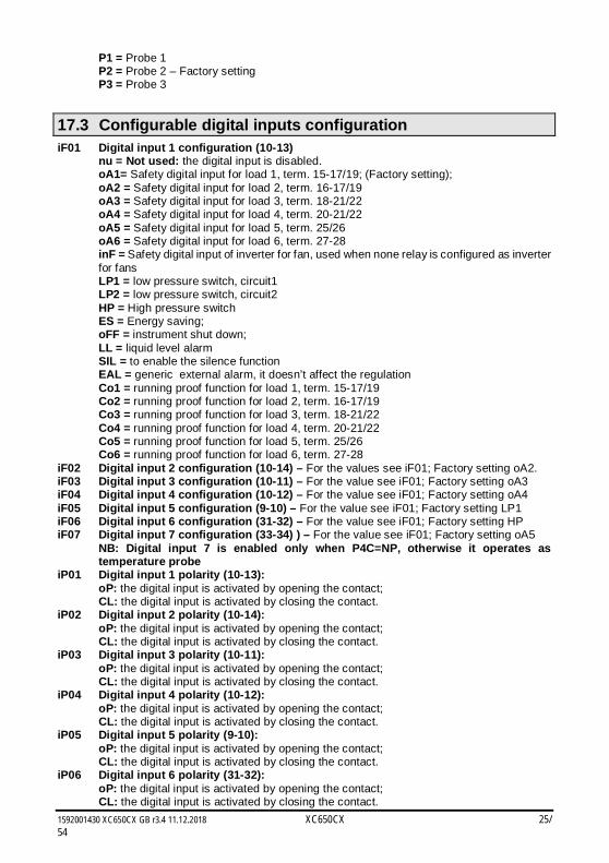
17.3 Configurable digital inputs configuration iF01 Digital input 1 configuration (10-13)
nu = Not used: the digital input is disabled. oA1= Safety digital input for load 1, term. 15-17/19; (Factory setting); oA2 = Safety digital input for load 2, term. 16-17/19 oA3 = Safety digital input for load 3, term. 18-21/22 oA4 = Safety digital input for load 4, term. 20-21/22 oA5 = Safety digital input for load 5, term. 25/26 oA6 = Safety digital input for load 6, term. 27-28 inF = Safety digital input of inverter for fan, used when none relay is configured as inverter for fans LP1 = low pressure switch, circuit1 LP2 = low pressure switch, circuit2 HP = High pressure switch ES = Energy saving; oFF = instrument shut down; LL = liquid level alarm SIL = to enable the silence function EAL = generic external alarm, it doesn’t affect the regulation Co1 = running proof function for load 1, term. 15-17/19 Co2 = running proof function for load 2, term. 16-17/19 Co3 = running proof function for load 3, term. 18-21/22 Co4 = running proof function for load 4, term. 20-21/22 Co5 = running proof function for load 5, term. 25/26 Co6 = running proof function for load 6, term. 27-28
iF02 Digital input 2 configuration (10-14) – For the values see iF01; Factory setting oA2. iF03 Digital input 3 configuration (10-11) – For the value see iF01; Factory setting oA3 iF04 Digital input 4 configuration (10-12) – For the value see iF01; Factory setting oA4 iF05 Digital input 5 configuration (9-10) – For the value see iF01; Factory setting LP1 iF06 Digital input 6 configuration (31-32) – For the value see iF01; Factory setting HP iF07 Digital input 7 configuration (33-34) ) – For the value see iF01; Factory setting oA5 NB: Digital input 7 is enabled only when P4C=NP, otherwise it operates as
temperature probe iP01 Digital input 1 polarity (10-13):
oP: the digital input is activated by opening the contact; CL: the digital input is activated by closing the contact.
iP02 Digital input 2 polarity (10-14): oP: the digital input is activated by opening the contact; CL: the digital input is activated by closing the contact.
iP03 Digital input 3 polarity (10-11): oP: the digital input is activated by opening the contact; CL: the digital input is activated by closing the contact.
iP04 Digital input 4 polarity (10-12): oP: the digital input is activated by opening the contact; CL: the digital input is activated by closing the contact.
iP05 Digital input 5 polarity (9-10): oP: the digital input is activated by opening the contact; CL: the digital input is activated by closing the contact.
iP06 Digital input 6 polarity (31-32): oP: the digital input is activated by opening the contact; CL: the digital input is activated by closing the contact.
1592001430 XC650CX GB r3.4 11.12.2018 XC650CX 26/54
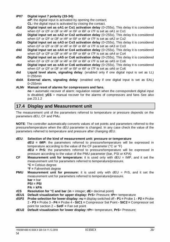
iP07 Digital input 7 polarity (33-34): oP: the digital input is activated by opening the contact; CL: the digital input is activated by closing the contact.
d1d Digital input set as oA1 or Co1 activation delay (0÷255s), This delay it is considered when i1F or i2F or i3F or i4F or i5F or i6F or i7F is set as oA1 or Co1
d2d Digital input set as oA2 or Co2 activation delay (0÷255s), This delay it is considered when i1F or i2F or i3F or i4F or i5F or i6F or i7F is set as oA2 or Co2
d3d Digital input set as oA3 or Co3 activation delay (0÷255s), This delay it is considered when i1F or i2F or i3F or i4F or i5F or i6F or i7F is set as oA3 or Co3
d4d Digital input set as oA4 or Co4 activation delay (0÷255s), This delay it is considered when i1F or i2F or i3F or i4F or i5F or i6F or i7F is set as oA4 or Co4
d5d Digital input set as oA5 or Co6 activation delay (0÷255s), This delay it is considered when i1F or i2F or i3F or i4F or i5F or i6F or i7F is set as oA5 or Co6
d6d Digital input set as oA6 or Co6 activation delay (0÷255s), This delay it is considered when i1F or i2F or i3F or i4F or i5F or i6F or i7F is set as oA6 or Co6
did Liquid level alarm, signaling delay: (enabled only if one digital input is set as LL) 0÷255min
didA External alarm, signaling delay: (enabled only if one digital input is set as EAL) 0÷255min
ALMr Manual reset of alarms for compressors and fans. no = automatic recover of alarm: regulation restart when the correspondent digital input
is disabled; yES = manual recover for the alarms of compressors and fans See also par.23.1.2
17.4 Display and Measurement unit The measurement unit of the parameters referred to temperature or pressure depends on the parameters dEU, CF and PMu. NOTE: The controller automatically converts values of set points and parameters referred to the pressure/temperature when the dEU parameter is changed. In any case check the value of the parameters referred to temperature and pressure after changing dEU. dEU: Selection of the kind of measurement unit: pressure or temperature
dEU = tMP: the parameters referred to pressure/temperature will be expressed in temperature according to the value of the CF parameter (°C or °F) dEU = PrS: the parameters referred to pressure/temperature will be expressed in pressure according to the value of the PMU parameter (bar, PSI or KPA)
CF Measurement unit for temperature: it is used only with dEU = tMP, and it set the measurement unit for parameters referred to temperature/pressure.
°C = Celsius degree °F = Fahrenheit degree PMU Measurement unit for pressure: it is used only with dEU = PrS, and it set the
measurement unit for parameters referred to temperature/pressure. bar = bar
PSI = PSI PA = kPA
rES Resolution for °C and bar (in = integer; dE= decimal point) dEU1 Default visualization for upper display: PrS= Pressure; tPr= temperature dSP2 Probe selection for lower display: nu = display switched off - P1 = Probe 1 - P2 = Probe
2 - P3 = Probe 3 - P4 = Probe 4 - StC1 = Compressor Set Point - StC2 = Compressor set point for section 2 – SetF = Fan set point
dEU2 Default visualization for lower display: tPr= temperature, PrS= Pressure;
1592001430 XC650CX GB r3.4 11.12.2018 XC650CX 27/54
17.5 Compressor regulation Pbd Proportional band or neutral zone width (0.1÷5.0bar/0.5÷30°C or 1÷150PSI/1÷50°F)
The band (or zone) is symmetrical compared to the target set point, with extremes: set-Pbd/2 ÷ set+Pbd/2. It is used as proportional band for PI algorithm. The measurement unit depends on the dEU, CF, PMU par.
rS Proportional band offset: PI band offset. It permits to move the proportional band of the PI. With rS=0 the band is between Set-Pbd/2 ÷ Set+Pbd/2;
inC Integration time: (0 ÷ 999s) PI integration time 2Pbd Proportional band or neutral zone width for circuit 2 (0.1÷5.0bar/0.5÷30°C or
1÷150PSI/1÷50°F) The band (or zone) is symmetrical compared to the target set point, with extremes: set-Pbd/2 ÷ set+Pbd/2. It is used as proportional band for PI algorithm. The measurement unit depends on the dEU, CF, PMU par.
2rS Proportional band offset for circuit 2: PI band offset. It permits to move the proportional band of the PI. With rS=0 the band is between Set-Pbd/2 ÷ Set+Pbd/2;
2inC Integration time for circuit 2: (0 ÷ 999s) PI integration time ton Inverter at maximum capacity before starting a new load (0÷255s) toF Inverter at minimum capacity before stopping a load (0÷255s) ESC Energy saving value for compressors: (-20÷20bar; -50÷50°C) this value is add to the
compressor set point. 2ESC Energy saving value for compressors of second circuit: (-20÷20bar; -50÷50°C) this
value is add to the compressor set point. onon: Minimum time between 2 following switching ON of the same compressor (0÷255
min). oFon: Minimum time between the switching off of a compressor and the following
switching on. (0÷255min). Note: usually onon is greater than oFon. don: Time delay between the insertion of two different compressors (0÷99.5min; res.
10s). doF: Time delay between switching off of two different compressors (0÷99.5 min; res.
10s) donF: Minimum time a stage stays switched ON (0÷99.5 min; res. 10s) MAon Maximum time for compressor ON (0 ÷ 24 h; with 0 this function is disabled.) If a
compressor keeps staying on for the MAon time, it’s switched off and it can restart after the oFon standard time.
FdLy: “don” delay enabled also for the first call. If enabled, the triggering of the step is delayed for a “don” value, respect to the call. (no = “don” not enabled; yES=”don” enabled)
FdLF “doF” delay enabled also for the first switching off. It enables the “doF” delay between the request of a release and the actual switching off. (no = “doF” not enabled; yES=”doF” enabled)
odo: Regulation delay on start-up: (0÷255s) on switching ON the instrument starts working after the time delay imposed in this parameter.
LSE: Minimum set point: The measurement unit depends on dEU parameter. It sets the minimum value that can be used for the set point, to prevent the end user from setting incorrect values.
HSE: Maximum set point: The measurement unit depends on dEU parameter. It sets the maximum acceptable value for set point.
2LSE: Minimum set point for circuit 2: The measurement unit depends on dEU parameter. It sets the minimum value that can be used for the set point, to prevent the end user from setting incorrect values.
2HSE: Maximum set point for circuit 2: The measurement unit depends on dEU parameter. It sets the maximum acceptable value for set point.
17.6 Liquid injection thermostat Lit: Set point ( °C) for cooling injection thermostat (0 ÷ 150°C) The reference probe is set
by LiPr parameter, the thermostat relay is given by the relay set as Lin.
1592001430 XC650CX GB r3.4 11.12.2018 XC650CX 28/54
Lid: Differential for cooling injection thermostat (0.1 ÷ 10.0) The reference probe is set by LiPr parameter
LiPr Probe for cooling injection thermostat: nP: function disabled P3: probe P3 (term. 3-4) P4: probe P4 (term. 33-34)
17.7 Fans regulation Pb Proportional band zone width (0.1÷30.0°C; 1÷50°F; 0.1÷10.0bar, 1÷150PSI;
10÷1000KPA). NOTE: Set the dEU par. and the target set point for fans before setting this
parameter. The band is symmetrical compared to the target set point, with extremes: SETF+Pb/2 ÷ SETF -Pb/2. The measurement unit depends on the dEU par.
ESF Energy saving value for fans: (-20÷20bar; -50÷50°C) this value is add to the fans set point.
PbES Band offset for fan regulation in ES (-50.0÷50.0°C; -90÷90°F; -20.0÷20.0bar; -300÷300PSI; -2000÷2000KPA). During energy saving
Fon Time delay between the insertion of two different fans (0÷255sec). FoF Time delay between switching off of two different compressors (0÷255 sec) LSF Minimum set point for fan: The measurement unit depends on dEU parameter. It sets
the minimum value that can be used for the set point, to prevent the end user from setting incorrect values.
HSF Maximum set point for fan: The measurement unit depends on dEU parameter. It sets the maximum acceptable value for set point.
17.8 Alarms – compressor section PAo: Alarm probe exclusion at power on. it is the period starting from instrument switch on,
before an alarm probe is signaled. (0÷255 min). During this time if the pressure is out of range all the compressor are switched on.
LAL: Low pressure (temperature) alarm – compressor section: The measurement unit depends on dEU parameter: (PA04 ÷ HAL bar; -50.0÷HAL °C; PA04÷HAL PSI; -58÷HAL °F) It’s independent from the set point. When the value LAL is reached the A03C alarm is enabled, (possibly after the tAo delay time).
HAL: High pressure (temperature) alarm– compressor section: The measurement unit depends on dEU parameter: (LAL ÷ PA20 bar; LAL÷150.0 °C; LAL÷PA20 PSI; LAL÷302 °F). It’s independent from the set point. When the value HAL is reached the A04C alarm is enabled, (possibly after the tAo delay time).
tAo: Low and High pressure (temperature) alarms delay– compressor section: (0÷255 min) time interval between the detection of a pressure (temperature) alarm condition and alarm signaling.
ELP Electronic pressure switch threshold: (-50°C÷STC1; -58°F÷STC1; PA04÷STC1); Pressure / Temperature value at which all the compressors are switched off. It has to be set some degrees above the mechanical low pressure switch value, in order to prevent mechanical low pressure activation.
2LAL: Low pressure (temperature) alarm, compressor section circuit 2: The measurement unit depends on dEU parameter: (3P04 ÷ 2HAL bar; -50.0÷2HAL °C; 3P04÷2HAL PSI; -58÷2HAL °F) It’s independent from the set point STC2. When the value 2LAL is reached the C2LA alarm is enabled, (possibly after the 2tAo delay time).
2HAL: High pressure (temperature) alarm, compressor section circuit 2: The measurement unit depends on dEU parameter: (2LAL ÷ 3P20 bar; 2LAL÷150.0 °C; 2LAL÷3P20 PSI; LAL÷302 °F). It’s independent from the set point STC2. When the value 2HAL is reached the C2HA alarm is enabled, (possibly after the 2tAo delay time).
1592001430 XC650CX GB r3.4 11.12.2018 XC650CX 29/54
2tAo: Low and High pressure (temperature) alarms delay, compressor section circuit 2: (0÷255 min) time interval between the detection of a pressure (temperature) alarm condition and alarm signaling.
2ELP Electronic pressure switch threshold, compressor section circuit 2: (-50°C÷STC2; -58°F÷STC2; 3P04÷STC2); Pressure / Temperature value at which all the compressors of second circuit are switched off. It has to be set some degrees above the mechanical low pressure switch value, in order to prevent mechanical low pressure activation.
SEr: Service request: (1÷999 hours, res. 10h; 0 = alarm excluded ) number of running hours after that the “A14” maintenance call is generated.
PEn: Low pressure-switch intervention numbers: (0÷15). If the low pressure-switch is enabled PEn times in the PEI interval, the controller is locked. Only the manually unlocking is possible. See also the alarms table at paragraph 23. Every time the pressure-switch is enabled all the compressor are turned off.
PEI: Pressure-switch interventions time (0÷255 min) Interval, linked to the Pen parameter, for counting interventions of the low pressure-switch..
SPr: number of steps engaged with faulty probe. (0÷6). 2PEn: Low pressure-switch intervention numbers for circuit 2: (0÷15). If the low pressure-
switch is enabled 2PEn times in the 2PEI interval, the compressors of the second circuit is locked. Only the manually unlocking is possible. See also the alarms table at paragraph 23. Every time the pressure-switch is enabled all the compressor are turned off.
2PEI: Pressure-switch interventions time for circuit 2 (0÷255 min) Interval, linked to the 2PEn parameter, for counting interventions of the low pressure-switch of circuit 2.
2SPr: Number of steps engaged with faulty probe of suction 2. (0÷6). PoPr Capacity engaged with faulty probe: (0÷100%) it’s used only if CtyP=dPo.
17.9 Alarms – fans section LAF: Low pressure alarm – fans section: The measurement unit depends on the dEU
parameter: (FA04 ÷ HAF bar; -50.0÷HAF °C; FA04÷HAF PSI; -58÷HAF °F) It’s independent from the set point. When the value LAF is reached the LA2 alarm is enabled, (possibly after the AFd delay time).
HAF: High pressure alarm – fans section: The measurement unit depends on the dEU parameter: (LAF÷FA20 bar; LAF÷150.0 °C; LAF÷FA20 PSI; LAF÷302 °F). It’s independent from the set point. When the value HAF is reached the HA2 alarm is enabled, (possibly after the AFd delay time).
AFd: Low and High pressure alarms delay – fans section: (0÷255 min) time interval between the detection of a pressure alarm condition in the fans section and alarm signaling.
HFC Compressors off with high pressure (temperature) alarm for fans no = compressors are not influenced by this alarm
yES = compressors are turned off in case of high pressure (temperature) alarm of fans dHF Interval between 2 compressors turning off in case of high pressure (temperature)
alarm for fans (0 ÷ 255 sec) PnF: High pressure-switch intervention numbers – fans section: (0÷15 with 0 the manually
unlocking is disabled) if the high pressure-switch is enabled PnF times in the PiF interval, the controller is locked. It can be unlocked only manually. See paragraph 23. Every time the pressure-switch is enabled all the compressors are turned off and all the fans are turned on.
PiF: Pressure-switch interventions time – fans section (0÷255 min) Interval, linked to the PEn parameter, for counting interventions of the high pressure-switch..
FPr Number of fans engaged with faulty probe. (0÷#fans).
1592001430 XC650CX GB r3.4 11.12.2018 XC650CX 30/54
17.10 Suction superheat of circuit 1 ASH0 Differential for low superheat pre-alarm. (0.1 to 30.0°C/ 1 to 60°F). The low superheat pre-alarm warning is sent when the superheat (SH) is lower than ASH2
(low superheat alarm threshold) + ASH0, possibly after the ASH1 delay. ASH1 Delay for signalling low superheat pre-alarm (0÷255sec)
If the superheat is below the ASH2+ASH0 threshold for ASH1 time the low superheat pre-alarm warning is sent.
ASH2 Low suction superheat alarm threshold (0.1÷15.0°C/ 1÷30°F). With SH < ASH2 the low superheat alarm is sent, possibly after the ASH3 delay
ASH3 Delay for signalling low superheat alarm (0÷255sec) If the superheat is below the ASH2 threshold for ASH3 time the low superheat alarm message is sent.
ASH4 Switching off compressors with low superheat alarm (No, Yes) ASH4 = no: compressors keep on working even with low superheat alarm. ASH4 = yES: compressors are stopped in case of low superheat alarm. ASH5 Differential to restart regulation after of low superheat alarm with compressor stop
(0.1 to 15.0°C/ 1 to 30°F). In case of regulation stop (ASH4= yES), it restarts when SH > ASH2+ASH5
ASH6 Delay to restart regulation after superheat > ASH2+ASH5 (0÷255 min). If the regulation is stopped because of low superheat alarm, it can restart when SH>ASH2+ASH5 for the ASH6 time.
ASH7 Superheat value to enable hot gas injecting valve (0.1 to 15.0°C/ 1 to 30°F) With a relay set as hot gas injection valve, (oA2 or oA3 or oA4 = HGi), the relay is on with
SH < ASH7 – ASH8. ASH8 Differential for ASH7 (0.1 to 30.0°C/ 1 to 60°F) ASH9 Probe selection for superheat monitoring (nP, P3, P4) ASH9 = nP no superheat control ASH9 = P3 the probe to calculate the superheat (SH) is the probe P3 (term. 38-42) ASH9 = P4 the probe to calculate the superheat (SH) is the probe P4 (term. 22-23). In
this case also the parameter P4C must be set as nt10 or nt86.
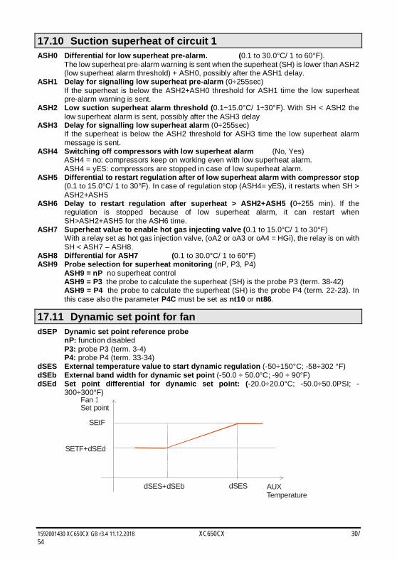
17.11 Dynamic set point for fan dSEP Dynamic set point reference probe
nP: function disabled P3: probe P3 (term. 3-4) P4: probe P4 (term. 33-34)
dSES External temperature value to start dynamic regulation (-50÷150°C; -58÷302 °F) dSEb External band width for dynamic set point (-50.0 ÷ 50.0°C; -90 ÷ 90°F) dSEd Set point differential for dynamic set point: (-20.0÷20.0°C; -50.0÷50.0PSI; -
300÷300°F) Fan 1Set point
AUXTemperature
SETF+dSEd
dSES+dSEb dSES
SEtF
1592001430 XC650CX GB r3.4 11.12.2018 XC650CX 31/54
17.12 Analog output 1 (optional) – Terminals 29-30 AoC Analog output 1 setting tEn = 0÷10V output cUr = 4-20mA output AOF Analog output 1 function
nu = analog output disabled; Inc1= To drive inverter for suction frequency compressor, suction of circuit 1; Inc2 = To drive inverter for suction frequency compressor, suction of circuit 2 inF= to drive ECI fan or inverter for fan
InCP Inverter compressor always activated at first: no: other compressors if available are allowed to start when the inverter compressor is
locked by safety timers. This allows the system to satisfy the cooling demand when the inverter compressor is unavailable.
yES: the inverter compressor is always started as first. If unavailable due to safety timers the regulation will be locked till timers will be over.
AOP Reference probe for the analog output 1 It is used only if AOP=FrE nP = not probe P3 = probe P3 P4 = probe P4 LAO Temperature value associated to minimum value of analog output (AOM)
(-50.0÷150.0°C, -58÷302°F). UAO Temperature value associated to the maximum value of analog output, 10V or
20mA (-50.0÷150.0°C, -58÷302°F). AOM Minimum value for analog output 1 (4 ÷ 20mA or 0÷10V) AOt Time of analog output 1 at max after the start (0÷15s) MPM Maximum % variation per minute of analog output 1: (nu; 1÷100) nu = not used: function disabled 1÷100 = it sets the maximum percentage variation per minute of the analog output. SAO Percentage of analog output 1 in case of probe failure: (0 ÷ 100%) AOH Maximum analog output 1 percentage when silence mode function is enabled
(0÷100)
17.13 Analog output 2 (optional) – Terminals 8-10 2AoC Analog output 2 setting tEn = 0÷10V output cUr = 4-20mA output 2AOF Analog output 2 function
nu = analog output disabled; Inc1= To drive inverter for suction frequency compressor, suction of circuit 1; Inc2 = To drive inverter for suction frequency compressor, suction of circuit 2 inF= to drive ECI fan or inverter for fan
2AOM Minimum value for analog output 2 (4 ÷ 20mA or 0÷10V) 2AOt Time of analog output 2 at max after the start (0÷15s) 2MPM Maximum % variation per minute for analog output 2: (nu; 1÷100) nu = not used: function disabled 1÷100 = it sets the maximum percentage variation per minute of the analog output. 2SAO Percentage of analog output 2 in case of probe failure: (0 ÷ 100%) 2AOH Maximum analog output 2 percentage when silence mode function is enabled
(0÷100)
17.14 Other tbA Alarm relay silencing: by pushing one of the keypad buttons. no= alarm relay stays on;
yES= alarm relay is switched off by pushing any keys. OAP Alarm relay output polarity: cL=closed when activated; oP= opened when activated
1592001430 XC650CX GB r3.4 11.12.2018 XC650CX 32/54
oFF Switching ON/OFF enabling from keyboard: (no = disabled; yES= enabled) It permits the switching ON/OFF of the instrument by pressing the SET key for more than 4s.
bUr Buzzer enabling no = the buzzer is not used in case of alarm yES = buzzer is used in case of alarm Adr: Serial address (1 –247) It is used in monitoring system. rEL Software release for internal use. Ptb Parameter table code: readable only. Pr2 Access to Pr2 parameter level
1592001430 XC650CX GB r3.4 11.12.2018 XC650CX 33/54
18. Even Capacity Compressors (CtyP = Spo)
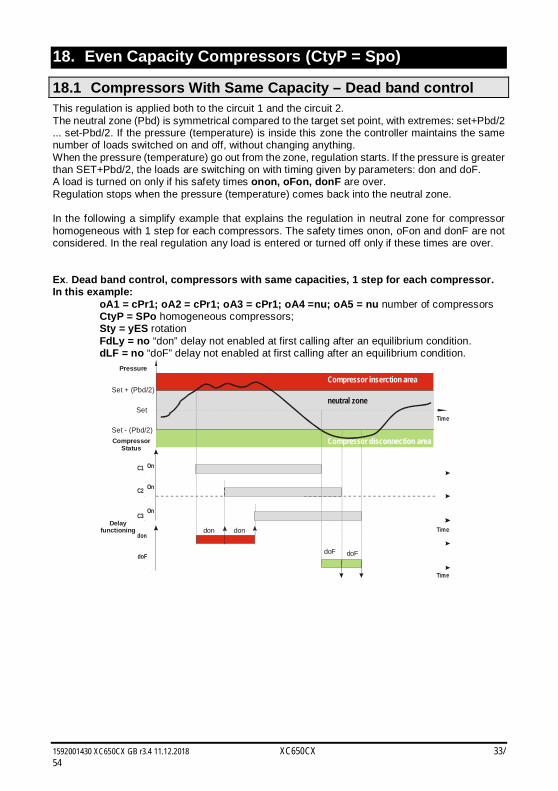
18.1 Compressors With Same Capacity – Dead band control This regulation is applied both to the circuit 1 and the circuit 2. The neutral zone (Pbd) is symmetrical compared to the target set point, with extremes: set+Pbd/2 ... set-Pbd/2. If the pressure (temperature) is inside this zone the controller maintains the same number of loads switched on and off, without changing anything. When the pressure (temperature) go out from the zone, regulation starts. If the pressure is greater than SET+Pbd/2, the loads are switching on with timing given by parameters: don and doF. A load is turned on only if his safety times onon, oFon, donF are over. Regulation stops when the pressure (temperature) comes back into the neutral zone. In the following a simplify example that explains the regulation in neutral zone for compressor homogeneous with 1 step for each compressors. The safety times onon, oFon and donF are not considered. In the real regulation any load is entered or turned off only if these times are over. Ex. Dead band control, compressors with same capacities, 1 step for each compressor. In this example:
oA1 = cPr1; oA2 = cPr1; oA3 = cPr1; oA4 =nu; oA5 = nu number of compressors CtyP = SPo homogeneous compressors; Sty = yES rotation FdLy = no “don” delay not enabled at first calling after an equilibrium condition. dLF = no “doF” delay not enabled at first calling after an equilibrium condition.
Set
C3
CompressorStatus
Time
Pressure
On
C2 On
C1 On
Compressor inserction area
neutral zone
don
doF
don
doFdoF
don
Delayfunctioning Time
Time
Set + (Pbd/2)
Set - (Pbd/2)Compressor disconnection area
1592001430 XC650CX GB r3.4 11.12.2018 XC650CX 34/54
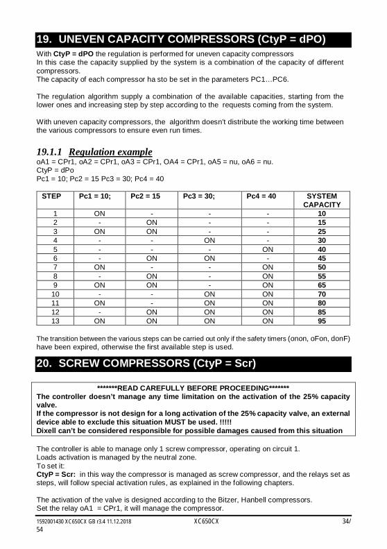
19. UNEVEN CAPACITY COMPRESSORS (CtyP = dPO) With CtyP = dPO the regulation is performed for uneven capacity compressors In this case the capacity supplied by the system is a combination of the capacity of different compressors. The capacity of each compressor ha sto be set in the parameters PC1…PC6. The regulation algorithm supply a combination of the available capacities, starting from the lower ones and increasing step by step according to the requests coming from the system. With uneven capacity compressors, the algorithm doesn’t distribute the working time between the various compressors to ensure even run times.
19.1.1 Regulation example oA1 = CPr1, oA2 = CPr1, oA3 = CPr1, OA4 = CPr1, oA5 = nu, oA6 = nu. CtyP = dPo Pc1 = 10; Pc2 = 15 Pc3 = 30; Pc4 = 40
STEP Pc1 = 10; Pc2 = 15 Pc3 = 30; Pc4 = 40 SYSTEM CAPACITY
1 ON - - - 10 2 - ON - - 15 3 ON ON - - 25 4 - - ON - 30 5 - - - ON 40 6 - ON ON - 45 7 ON - - ON 50 8 - ON - ON 55 9 ON ON - ON 65 10 - - ON ON 70 11 ON - ON ON 80 12 - ON ON ON 85 13 ON ON ON ON 95
The transition between the various steps can be carried out only if the safety timers (onon, oFon, donF) have been expired, otherwise the first available step is used.
20. SCREW COMPRESSORS (CtyP = Scr)
*******READ CAREFULLY BEFORE PROCEEDING******* The controller doesn’t manage any time limitation on the activation of the 25% capacity valve. If the compressor is not design for a long activation of the 25% capacity valve, an external device able to exclude this situation MUST be used. !!!!! Dixell can’t be considered responsible for possible damages caused from this situation The controller is able to manage only 1 screw compressor, operating on circuit 1. Loads activation is managed by the neutral zone. To set it: CtyP = Scr: in this way the compressor is managed as screw compressor, and the relays set as steps, will follow special activation rules, as explained in the following chapters. The activation of the valve is designed according to the Bitzer, Hanbell compressors. Set the relay oA1 = CPr1, it will manage the compressor.
1592001430 XC650CX GB r3.4 11.12.2018 XC650CX 35/54
Set the oA2, oA3 and oA4 as “StP”.
20.1 Regulation with screw compressors like Bitzer/ Hanbell/ Refcomp etc Screw compressors like Bitzer use up to 3 valves for the power regulation.
20.1.1 Relay activation ES. Compressor with 4 steps: oA1 = CPr1; oA2 = StP; oA3 = StP; oA4 = StP; CtyP = Scr a. Activation with valves ON due to voltage presence (StP=cL).
oA1 = Screw1 oA2 = StP oA3 = StP oA4 = StP Step 1 (25%) ON ON OFF OFF Step 2 (50%) ON OFF ON OFF Step 3 (75%) ON OFF OFF ON Step 4 (100%) ON OFF OFF OFF
b. Activation with valves ON due to voltage absence (StP=oP).
C1 = Screw1 C2 = stp C3 = stp C4 = stp Step 1 (25%) ON OFF ON ON Step 2 (50%) ON ON OFF ON Step 3 (75%) ON ON ON OFF Step 4 (100%) ON ON ON ON
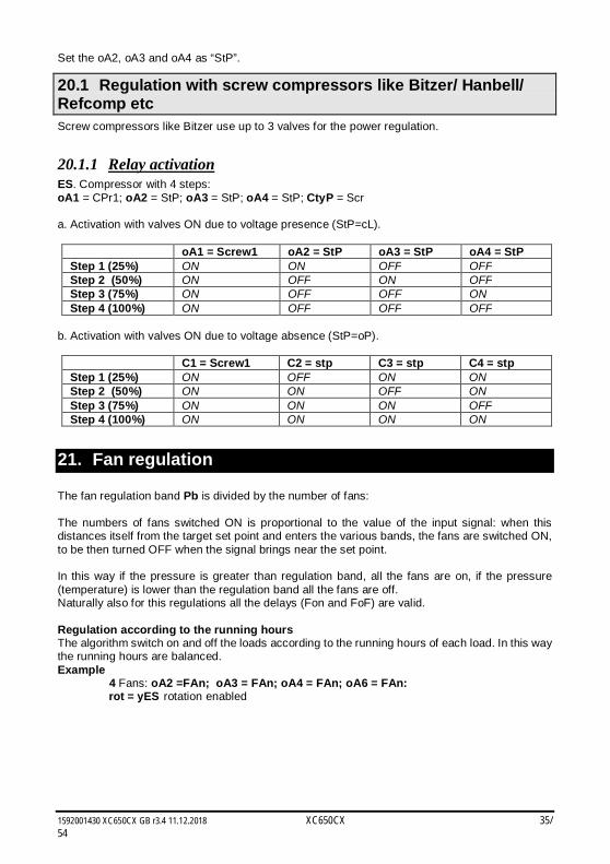
21. Fan regulation The fan regulation band Pb is divided by the number of fans: The numbers of fans switched ON is proportional to the value of the input signal: when this distances itself from the target set point and enters the various bands, the fans are switched ON, to be then turned OFF when the signal brings near the set point. In this way if the pressure is greater than regulation band, all the fans are on, if the pressure (temperature) is lower than the regulation band all the fans are off. Naturally also for this regulations all the delays (Fon and FoF) are valid. Regulation according to the running hours The algorithm switch on and off the loads according to the running hours of each load. In this way the running hours are balanced. Example 4 Fans: oA2 =FAn; oA3 = FAn; oA4 = FAn; oA6 = FAn:
rot = yES rotation enabled
1592001430 XC650CX GB r3.4 11.12.2018 XC650CX 36/54
F1
F2
F3
F4
SETF
Set+Pb/2
Set-Pb/2
ZIC
Set+Pb/4
Set-Pb/4
Fon
FoF
ALL LOADS ON
ALL LOADS OFF
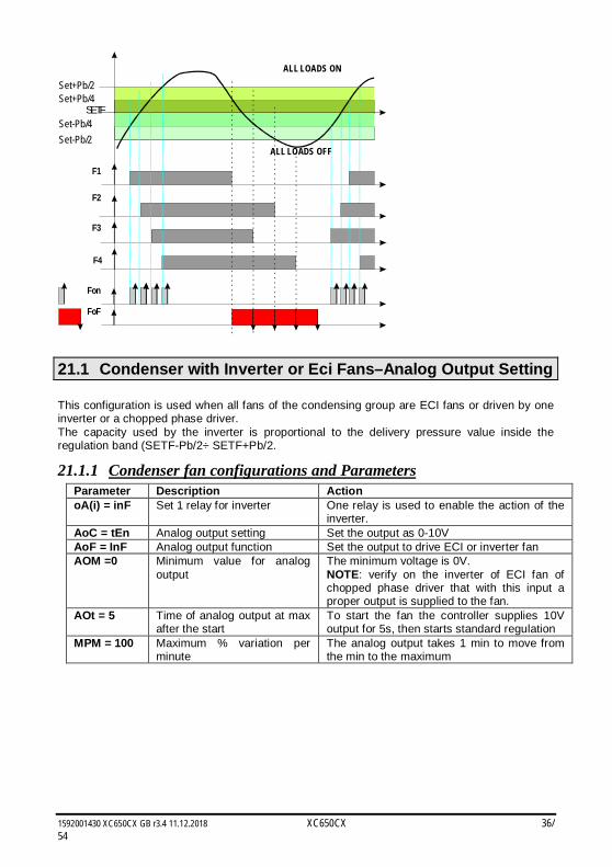
21.1 Condenser with Inverter or Eci Fans–Analog Output Setting This configuration is used when all fans of the condensing group are ECI fans or driven by one inverter or a chopped phase driver. The capacity used by the inverter is proportional to the delivery pressure value inside the regulation band (SETF-Pb/2÷ SETF+Pb/2.
21.1.1 Condenser fan configurations and Parameters Parameter Description Action oA(i) = inF Set 1 relay for inverter One relay is used to enable the action of the
inverter. AoC = tEn Analog output setting Set the output as 0-10V AoF = InF Analog output function Set the output to drive ECI or inverter fan AOM =0 Minimum value for analog
output The minimum voltage is 0V. NOTE: verify on the inverter of ECI fan of chopped phase driver that with this input a proper output is supplied to the fan.
AOt = 5 Time of analog output at max after the start
To start the fan the controller supplies 10V output for 5s, then starts standard regulation
MPM = 100 Maximum % variation per minute
The analog output takes 1 min to move from the min to the maximum
1592001430 XC650CX GB r3.4 11.12.2018 XC650CX 37/54
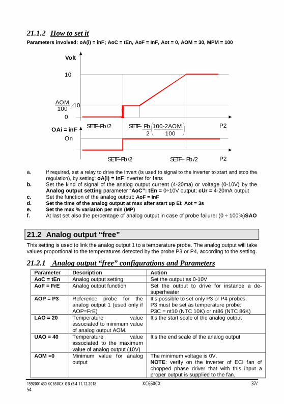
21.1.2 How to set it Parameters involved: oA(i) = inF; AoC = tEn, AoF = InF, Aot = 0, AOM = 30, MPM = 100
P2
Volt
10
0
AOM100 10
P2SETF-Pb/2 SETF+ Pb /2
OnOAi = inF SETF-Pb/2 SETF- Pb 100-2AOM
2 100
a. If required, set a relay to drive the invert (is used to signal to the inverter to start and stop the regulation), by setting: oA(i) = inF inverter for fans
b. Set the kind of signal of the analog output current (4-20ma) or voltage (0-10V) by the Analog output setting parameter “AoC”: tEn = 0÷10V output; cUr = 4-20mA output
c. Set the function of the analog output: AoF = InF d. Set the time of the analog output at max after start up EI: Aot = 3s e. Set the max % variation per min (MP) f. At last set also the percentage of analog output in case of probe failure: (0 ÷ 100%)SAO
21.2 Analog output “free” This setting is used to link the analog output 1 to a temperature probe. The analog output will take values proportional to the temperatures detected by the probe P3 or P4, according to the setting.
21.2.1 Analog output “free” configurations and Parameters Parameter Description Action AoC = tEn Analog output setting Set the output as 0-10V AoF = FrE Analog output function Set the output to drive for instance a de-
superheater AOP = P3 Reference probe for the
analog output 1 (used only if AOP=FrE)
It’s possible to set only P3 or P4 probes. P3 must be set as temperature probe: P3C = nt10 (NTC 10K) or nt86 (NTC 86K)
LAO = 20 Temperature value associated to minimum value of analog output AOM.
It’s the start scale of the analog output
UAO = 40 Temperature value associated to the maximum value of analog output (10V)
It’s the end scale of the analog output
AOM =0 Minimum value for analog output
The minimum voltage is 0V. NOTE: verify on the inverter of ECI fan of chopped phase driver that with this input a proper output is supplied to the fan.
1592001430 XC650CX GB r3.4 11.12.2018 XC650CX 38/54
Parameter Description Action AOt = 5 Time of analog output at max
after the start With AOt = 5 the controller supplies 10V output for 5s at fan start, then starts standard regulation
MPM = 100 Maximum % variation per minute
The analog output takes 1 min to move from the min to the maximum
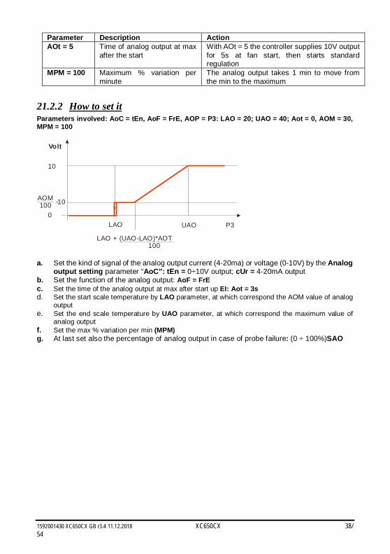
21.2.2 How to set it Parameters involved: AoC = tEn, AoF = FrE, AOP = P3: LAO = 20; UAO = 40; Aot = 0, AOM = 30, MPM = 100
P3
Volt
10
0
AOM100 10
LAO UAO
LAO + (UAO-LAO)*AOT 100
a. Set the kind of signal of the analog output current (4-20ma) or voltage (0-10V) by the Analog
output setting parameter “AoC”: tEn = 0÷10V output; cUr = 4-20mA output b. Set the function of the analog output: AoF = FrE c. Set the time of the analog output at max after start up EI: Aot = 3s d. Set the start scale temperature by LAO parameter, at which correspond the AOM value of analog
output e. Set the end scale temperature by UAO parameter, at which correspond the maximum value of
analog output f. Set the max % variation per min (MPM) g. At last set also the percentage of analog output in case of probe failure: (0 ÷ 100%)SAO
1592001430 XC650CX GB r3.4 11.12.2018 XC650CX 39/54
22. Additional functions
22.1 Compressor running proof function The digital inputs are normally used to signal a compressor or fan failure It’s also possible to set the digital inputs for running proof signalling. That means when compressor relay is activated, after a configurable delay the digital input related to the compressor should goes on too (usually a contact from compressor contactor) and the controller has the “confirmation” that compressor is running. If it doesn’t, that means something is wrong between the controller and the compressor itself.
22.1.1 Parameters and settings The parameters involved are: - iF01, iF02, iF03, iF04, iF05, iF06, iF07: configuration of dig input 1, 2, 3, 4, 5, 6, 7, with the related polarity: - iP01, iP02, iP03, iP04, iP05, iP06, iP07: polarity of digital input 1, 2, 3, 4, 5, 6, 7, with the related delay before alarm signalling: - d1d, d2d, d3d, d4d, d5d, d6d: delay before signalling alarm with digital input set
respectively as oA1 or Co1, oA2 or Co2, oA3 or Co3, oA4 or Co4, oA5 or Co5, oA6 or Co6.
22.1.2 Alarms related Label Meaning Reaason Action Reset FC01… FC06
Running proof alarm with automatic recover
The digital input set as Co1.. Co6 has not been activated by d1d, … d4d time
The compressor 1..4 is switched off and the safety timers start
Automatic – when safety timers are over
LC01… LC06
Running proof alarm with manual recover
5 running proof alarms happened in a hour.
The compressor 1..4 is switched off
Manual by means: - Controller off-on - Reset by keyboard - Reset by monitoring system
22.1.3 Example EI: Rack with 2 compressors, with compressor safeties and running proof circuit for each compressor: Compressor 1 on relay 1: oA1 = CPr1 Compressor 2 on relay 2: oA2 = CPr1 Safety for compressor 1 on digital input 1: iF01 = oA1 Safety for compressor 2 on digital input 2: iF02 = oA2 Running proof circuit for compressor 1 on digital input 3: iF03 = Co1 Running proof circuit for compressor 2 on digital input 4: iF04 = Co2 2 seconds delay before signalling alarm and stopping the compressor 1: d1d = 2 2 seconds delay before signalling alarm and stopping the compressor 2: d2d = 2 When the compressor 1 (or 2) starts, if by 2sec the digital input 3 (or 4) is not activated (running proof function) the FC01 alarm is signalled and the compressor is stopped. Alarm recover as soon as the safety timers of the compressor (onon, ofon) are over and compressor come back available for regulation. After 5 consecutive alarms, the alarms move from automatic restart to manual restart and it must be reset by Keyboard, of by switching off and on the controller.
1592001430 XC650CX GB r3.4 11.12.2018 XC650CX 40/54
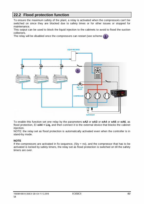
22.2 Flood protection function To ensure the maximum safety of the plant, a relay is activated when the compressors can’t be switched on since they are blocked due to safety times or for other issues or stopped for maintenance. This output can be used to block the liquid injection to the cabinets to avoid to flood the suction collectors. The relay will be disabled once the compressors can restart (see scheme ).
To enable this function set one relay by the parameters oA2 or oA3 or oA4 or oA5 or oA6, as flood protection, EI oA4 = Liq, and then connect it to the external device that blocks the cabinet injection. NOTE: the relay set as flood protection is automatically activated even when the controller is in stand-by mode. NOTE If the compressors are activated in fix sequence, (Sty = no), and the compressor that has to be activated is locked by safety timers, the relay set as flood protection is switched on till the safety timers are over.
1
1592001430 XC650CX GB r3.4 11.12.2018 XC650CX 41/54
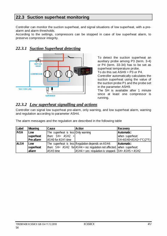
22.3 Suction superheat monitoring Controller can monitor the suction superheat, and signal situations of low superheat, with a pre-alarm and alarm thresholds. According to the settings, compressors can be stopped in case of low superheat alarm, to preserve compressor integrity.
22.3.1 Suction Superheat detecting To detect the suction superheat an auxiliary probe among P3 (term. 3-4) or P4 (term. 33-34) has to be set as superheat temperature probe. To do this set ASH9 = P3 or P4. Controller automatically calculates the suction superheat using the value of the suction probe P1 and the probe set in the parameter ASH9. The SH is available after 1 minute since at least one compressor is running.
22.3.2 Low superheat signalling and actions Controller can signal low superheat pre-alarm, only warning, and low superheat alarm, warning and regulation according to parameter ASH4. The alarm messages and the regulation are described in the following table Label Meaning Cause Action Recovery PrSH Low
superheat Pre-allarm
The superheat is less than: SH< ASH2 + ASH0 for ASH1 time
Only warning Automatic: when superheat: SH>ASH0+ASH2+1°C(2°F)
ALSH Low superheat allarm
The superheat is less than: SH< ASH2 for ASH3 time
Regulation depends on ASH4: ASH4 = no: regulation not affected. ASH4 = yes: regulation is stopped.
Automatic: when superheat: SH> ASH5 + ASH2
1592001430 XC650CX GB r3.4 11.12.2018 XC650CX 42/54
22.4 Hot gas injection valve Controller can manage a hot gas injection valve to increase suction superheat. See above figure.
22.4.1 Parameters A relay must be set as hot gas valve: oA2 or oA3 or oA4 or oA5 or oA6= HGi, and an auxiliary probe among P3 (term. 3-4) or P4 (term. 33-34) has to be set as superheat temperature probe ASH9 = P3 or P4. Then the following parameters: ASH7 Superheat value to enable hot gas injecting valve (0.1 to 15.0°C/ 1 to 30°F) ASH8 Differential for ASH7 (0.1 to 30.0°C/ 1 to 60°F)
22.4.2 Regulation: The regulation respects the following schema: Superheat < ASH7 – ASH8 HGi on Superheat > ASH7 HGi off ASH7 < Superheat < ASH7 – ASH8 Status. Dove SH = valore di SH
22.4.3 Special conditions a. With ASH9 = nP: none probe set as SH probe and one relays set as HGi (valve for hot
gas injection) the configuration error is displayed “no Probe For SH”, and the relay set as HGi is never activated..
b. If the probe used to calculate the SH is in error the related probe fault alarm is generated (P3 or P4) and the HGi relay is not activated.
23. Alarm list Usually alarm conditions are signaled by means of: 1. Activation of alarm output 2. Buzzer activation 3. Message on proper display 4. Log of alarm: code and duration. The table at paragraph 23.3
23.1 Types of alarms and signaling managed
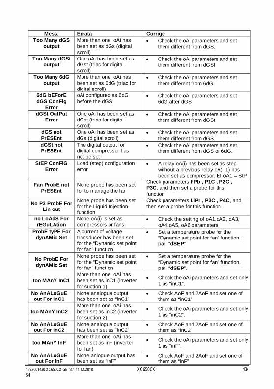
23.1.1 A12: Configuration alarm The following configuration parameters are checked after each modification.:
OA1 OA6 Outputs 2- 6 configuration P2C Second probe configuration.
When these parameters are set in wrong way an alarm message is generated: the label A12 is shown on the upper display, while the lower display the following messages are shown:
1592001430 XC650CX GB r3.4 11.12.2018 XC650CX 43/54
Mess. Errata Corrige Too Many dGS
output More than one oAi has been set as dGs (digital scroll)
Check the oAi parameters and set them different from dGS.
Too Many dGSt output
One oAi has been set as dGst (triac for digital scroll)
Check the oAi parameters and set them different from dGSt.
Too Many 6dG output
More than one oAi has been set as 6dG (triac for digital scroll)
Check the oAi parameters and set them different from 6dG.
6dG bEForE dGS ConFig
Error
oAi configured as 6dG before the dGS
Check the oAi parameters and set 6dG after dGS.
dGSt OutPut Error
One oAi has been set as dGst (triac for digital scroll)
Check the oAi parameters and set them different from dGSt.
dGS not PrESEnt
One oAi has been set as dGs (digital scroll)
Check the oAi parameters and set them different from dGS.
dGSt not PrESEnt
The digital output for digital compressor has not be set
Check the oAi parameters and set them different from dGS or 6dG.
StEP ConFiG Error
Load (step) configuration error
A relay oA(i) has been set as step without a previous relay oA(i-1) has been set as compressor. EI oA1 = StP
Fan ProbE not PrESEnt
None probe has been set for to manage the fan
Check parameters FPb , P1C , P2C , P3C, and then set a probe for this function
No P3 ProbE For Lin out
None probe has been set for the Liquid Injection function
Check parameters LiPr , P3C , P4C, and then set a probe for this function.
no LoAdS For rEGuLAtion
None oA(i) is set as compressors or fans
Check the setting of oA1,oA2, oA3, oA4,oA5, oA6 parameters
ProbE tyPE For dynAMic Set
A current of voltage transducer has been set for the “Dynamic set point for fan” function
Set a temperature probe for the “Dynamic set point for fan” function, par. “dSEP”
No ProbE For dynAMic Set
None probe has been set for the “Dynamic set point for fan” function
Set a temperature probe for the “Dynamic set point for fan” function, par. “dSEP”.
too MAnY InC1 More than one oAi has been set as inC1 (inverter for suction 1)
Check the oAi parameters and set only 1 as “inC1”.
No AnALoGuE out For InC1
None analogue output has been set as “inC1”
Check AoF and 2AoF and set one of them as “inC1”
too MAnY InC2 More than one oAi has been set as inC2 (inverter for suction 2)
Check the oAi parameters and set only 1 as “inC2”.
No AnALoGuE out For InC2
None analogue output has been set as “inC2”
Check AoF and 2AoF and set one of them as “inC2”
too MAnY InF More than one oAi has been set as inF (inverter for fan)
Check the oAi parameters and set only 1 as “inF”.
No AnALoGuE out For InF
None anlogue output has been set as “inF”
Check AoF and 2AoF and set one of them as “inF”
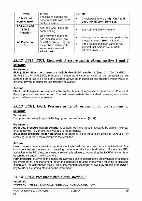
1592001430 XC650CX GB r3.4 11.12.2018 XC650CX 44/54
Mess. Errata Corrige
CPr Circuit conFiG Error
The kind of outputs are not compatible with the 2 suction circuits
Check parameters oA(i) , CtyP and set CtyP different from Scr.
AO1 And AO2 SAME
Function
AoF and 2AoF have the same setting Set AoF and 2AoF properly.
no Probe For SH
One relay is set as hot gas injection valve (oA2 or oA3 or oA4 = HGi), but the probe to detected th superheat is missed: ASH9 = nP
Set a probe to detect the superheat by the parameter ASH9 = P3 or P4.
If the hot gas injection valve is not present, set oA2 or oA3 or oA4 different from HGi.
23.1.2 E01L, E02L Electronic Pressure switch alarm, suction 1 and 2 sections Parameters ELP (2ELP): Electronic pressure switch threshold, section 1 (and 2): (-50°C÷SETC; -58°F÷SETC; PA04÷SETC); Pressure / Temperature value at which all the compressors are switched off. It has to be set some degrees above the mechanical low pressure switch value, in order to prevent mechanical low pressure activation. Actions Electronic low pressure: every time the suction temperature/pressure is less than ELP value all the compressors are switched off. The instrument restarts the standard operating mode when pressure/ temperature increases.
23.1.3 E0H1, E0L1, Pressure switch alarm, suction 1, and condensing sections Terminals Low pressure switch 1 input: 9-10, high pressure switch input: [31-32]. Parameters iP05: Low pressure switch polarity: It establishes if the input is activated by giving (iP05=cL) or by removing (iP05=oP) main voltage to the terminals. iP06: High pressure switch polarity: It establishes if the input is by giving (iP06=cL) or by removing (iP06=oP) main voltage to the terminals. Actions Low pressure: every time the inputs are activated all the compressors are switched off. The instrument restart the standard operating mode when the input is disabled. If there are PEn activation in the PEi time, only manual resetting is allowed, by pressing the DOWN key for 3s or by turning off and on the instrument. High pressure: every time the inputs are activated all the compressors are switched off and fans are switched on. The instrument restart the standard operating mode when the input is disabled. If there are PnF activation in the PiF time, only manual resetting is allowed, by pressing the DOWN key for 3s or by turning off and on the instrument.
23.1.4 E0L2, Pressure switch alarm, suction 2 Terminals WARNING: THESE TERMINALS FREE VOLTAGE CONNECTION
1592001430 XC650CX GB r3.4 11.12.2018 XC650CX 45/54
Set iF07 as low pressure switch 2 input: 33-34 Parameters iP07: Low pressure switch 2 polarity: It establishes if the input is activated by giving (iP07=cL) or by removing (iP07=oP) main voltage to the terminals. Actions Low pressure switch 2: every time the inputs are activated all the compressors of circuit 2 are switched off. The instrument restart the standard operating mode when the input is disabled. If there are Pen2 activation in the Pei2 time, only manual resetting is allowed, by pressing the DOWN key for 3s or by turning off and on the instrument.
23.1.5 EA1÷EA6: Compressors and fans safeties alarm. Terminals WARNING: THESE TERMINALS REQUIRE A FREE OF VOLTAGE CONNECTION. The terminals (from 11 TO 14) really used depends on the number of loads. The protections regarding the compressors and fans are connected to these inputs. If one of these protections is enabling (E.I. for lack of oil or overheating, etc,) the corresponding load is turn off. Parameters iP01, iP02, iP03, iP04,: establish if the input is activated by closing (cL) or by opening (=oP) the terminals. Actions Every time one input is activated the corresponding output is turned off. Recovery Recovery depends on ALMr parameter: With ALMr = no The instrument restart the standard operating mode when the input is disabled. With ALMr = yES manual recover for the alarms of compressors and fans. Push the DOWN key for 3s.
23.1.6 P1, P2; P3,P4: probe failure alarm It is generated by failure in the probe P1, P2 , P3 or P4. In case of P1 fault, number of steps engaged depends on the SPr parameter In case of P2 fault, number of fans engaged depends on the FPr parameter If the P3 or P4 probes are used for dynamic set point
The function is disabled and only the standard set point is used.
Recovery Automatic as soon as probe restarts working.
23.1.7 C1HA, C1LA, C2HA, C2LA F-HA, F-LA High and low pressure (temperature) alarms for compressors or fans This alarm signals that the pressure (temperature) is out of limits established by parameters LAL and HAL for compressors and LAF –HAF for fans. The tAo and AFd parameters set the delay between alarm condition and alarm signaling. Action The alarm is signaled with standard action. The outputs are unchanged.
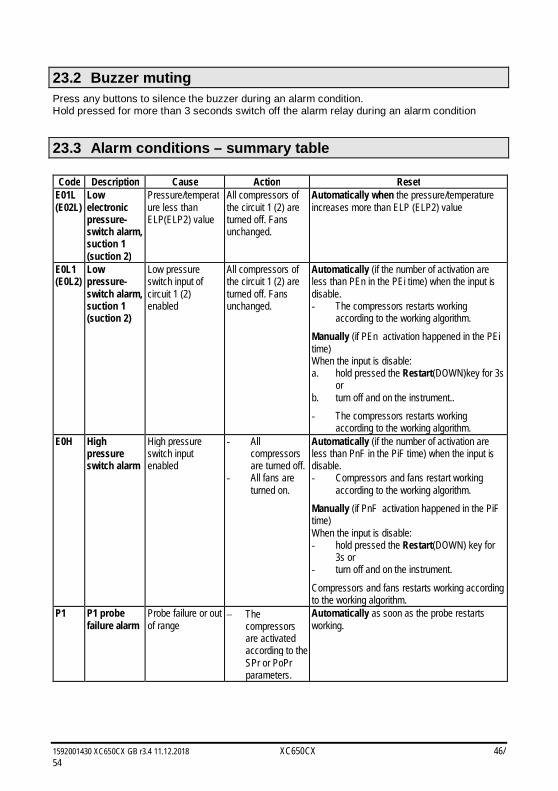
1592001430 XC650CX GB r3.4 11.12.2018 XC650CX 46/54
23.2 Buzzer muting Press any buttons to silence the buzzer during an alarm condition. Hold pressed for more than 3 seconds switch off the alarm relay during an alarm condition
23.3 Alarm conditions – summary table
Code Description Cause Action Reset E01L (E02L)
Low electronic pressure-switch alarm, suction 1 (suction 2)
Pressure/temperature less than ELP(ELP2) value
All compressors of the circuit 1 (2) are turned off. Fans unchanged.
Automatically when the pressure/temperature increases more than ELP (ELP2) value
E0L1 (E0L2)
Low pressure-switch alarm, suction 1 (suction 2)
Low pressure switch input of circuit 1 (2) enabled
All compressors of the circuit 1 (2) are turned off. Fans unchanged.
Automatically (if the number of activation are less than PEn in the PEi time) when the input is disable. - The compressors restarts working
according to the working algorithm.
Manually (if PEn activation happened in the PEi time) When the input is disable: a. hold pressed the Restart(DOWN)key for 3s
or b. turn off and on the instrument..
- The compressors restarts working according to the working algorithm.
E0H High pressure switch alarm
High pressure switch input enabled
- All compressors are turned off.
- All fans are turned on.
Automatically (if the number of activation are less than PnF in the PiF time) when the input is disable. - Compressors and fans restart working
according to the working algorithm.
Manually (if PnF activation happened in the PiF time) When the input is disable: - hold pressed the Restart(DOWN) key for
3s or - turn off and on the instrument.
Compressors and fans restarts working according to the working algorithm.
P1 P1 probe failure alarm
Probe failure or out of range
The compressors are activated according to the SPr or PoPr parameters.
Automatically as soon as the probe restarts working.
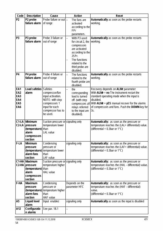
1592001430 XC650CX GB r3.4 11.12.2018 XC650CX 47/54
Code Description Cause Action Reset P2 P2 probe
failure alarm Probe failure or out of range
The fans are activated according to the FPr parameters.
Automatically as soon as the probe restarts working.
P3 P3 probe failure alarm
Probe 3 failure or out of range
With P3 used for circuit 2, the compressors are activated according to the 2SPr.
The functions related to the third probe are disabled.
Automatically as soon as the probe restarts working.
P4 P4 probe failure alarm
Probe 4 failure or out of range
The functions related to the fourth probe are disabled.
Automatically as soon as the probe restarts working.
EA1 EA2 EA3 EA4 EA5 EA6
Load safeties alarm
Safeties compressor/fan input activation. NOTE: with step compressors 1 input for each compressor has to be used.
the corresponding load is turned off. (with step compressors all relays referred to the input are disabled).
Recovery depends on ALMr parameter: With ALMr = no The instrument restart the standard operating mode when the input is disabled. With ALMr = yES manual recover for the alarms of compressors and fans. Push the DOWN key for 3s.
C1-LA C2-LA
Minimum pressure (temperature) alarm compressors section
Suction pressure or temperature lower than LAL value
signaling only Automatically: as soon as the pressure or temperature reaches the (LAL+ differential) value. (differential = 0.3bar or 1°C)
F-LA Minimum pressure (temperature) alarm fans section
Condensing pressure or temperature lower than LAF value
signaling only Automatically: as soon as the pressure or temperature reaches the (LAF+ differential) value. (differential = 0.3bar or 1°C)
C1-HA C2-HA
Maximum pressure (temperature) alarm compressors section
Suction pressure or temperature higher than HAL value
signaling only Automatically: as soon as the pressure or temperature reaches the (HAL - differential) value. (differential = 0.3bar or 1°C)
F-HA Maximum pressure (temperature) alarm fans section
Condensing pressure or temperature higher than HAF value
Depends on the parameter HFC
Automatically: as soon as the pressure or temperature reaches the (HAF - differential) value. (differential = 0.3bar or 1°C)
A5 Liquid level alarm
Input enabled signaling only Automatically as soon as the input is disabled
A12 Configuration alarms
See par. 18.1
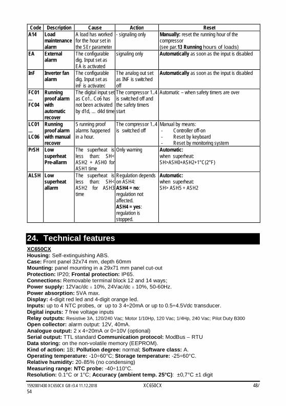
1592001430 XC650CX GB r3.4 11.12.2018 XC650CX 48/54
Code Description Cause Action Reset A14 Load
maintenance alarm
A load has worked for the hour set in the SEr parameter
- signaling only
Manually: reset the running hour of the compressor (see par.13 Running hours of loads)
EA External alarm
The configurable dig. Input set as EA is activated
signaling only Automatically as soon as the input is disabled
InF Inverter fan alarm
The configurable dig. Input set as inF is activated
The analog out set as INF is switched off
Automatically as soon as the input is disabled
FC01… FC04
Running proof alarm with automatic recover
The digital input set as Co1.. Co6 has not been activated by d1d, … d4d time
The compressor 1..4 is switched off and the safety timers start
Automatic – when safety timers are over
LC01… LC06
Running proof alarm with manual recover
5 running proof alarms happened in a hour.
The compressor 1..4 is switched off
Manual by means: - Controller off-on - Reset by keyboard - Reset by monitoring system
PrSH Low superheat Pre-allarm
The superheat is less than: SH< ASH2 + ASH0 for ASH1 time
Only warning Automatic: when superheat: SH>ASH0+ASH2+1°C(2°F)
ALSH Low superheat allarm
The superheat is less than: SH< ASH2 for ASH3 time
Regulation depends on ASH4: ASH4 = no: regulation not affected. ASH4 = yes: regulation is stopped.
Automatic: when superheat: SH> ASH5 + ASH2
24. Technical features XC650CX Housing: Self-extinguishing ABS. Case: Front panel 32x74 mm, depth 60mm Mounting: panel mounting in a 29x71 mm panel cut-out Protection: IP20; Frontal protection: IP65. Connections: Removable terminal block 12 and 14 ways; Power supply: 12Vac/dc 10%, 24Vac/dc 10%, 50-60Hz. Power absorption: 5VA max. Display: 4-digit red led and 4-digit orange led. Inputs: up to 4 NTC probes, or up to 3 4÷20mA or up to 0.5÷4.5Vdc transducer. Digital inputs: 7 free voltage inputs Relay outputs: Resistive 3A, 120/240 Vac; Motor 1/10Hp, 120 Vac; 1/4Hp, 240 Vac; Pilot Duty B300 Open collector: alarm output: 12V, 40mA. Analogue output: 2 x 4÷20mA or 0÷10V (optional) Serial output: TTL standard Communication protocol: ModBus – RTU Data storing: on the non-volatile memory (EEPROM). Kind of action: 1B; Pollution degree: normal; Software class: A. Operating temperature: -10÷60°C; Storage temperature: -25÷60°C. Relative humidity: 2085% (no condensing) Measuring range: NTC probe: -40÷110°C. Resolution: 0.1°C or 1°C; Accuracy (ambient temp. 25°C): ±0,7°C ±1 digit
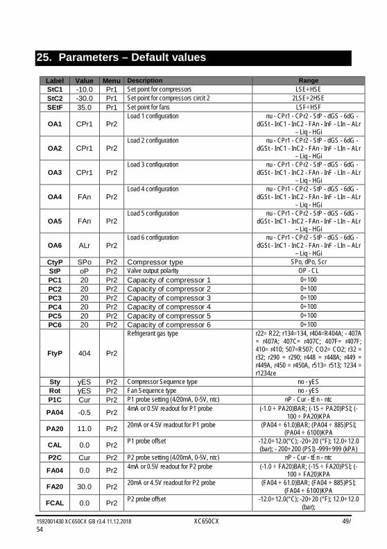
1592001430 XC650CX GB r3.4 11.12.2018 XC650CX 49/54
25. Parameters – Default values
Label Value Menu Description Range StC1 -10.0 Pr1 Set point for compressors LSE÷HSE StC2 -30.0 Pr1 Set point for compressors circit 2 2LSE÷2HSE SEtF 35.0 Pr1 Set point for fans LSF÷HSF
OA1 CPr1 Pr2 Load 1 configuration nu - CPr1 - CPr2 - StP - dGS - 6dG -
dGSt - InC1 - InC2 - FAn - InF - LIn – ALr – Liq - HGi
OA2 CPr1 Pr2 Load 2 configuration nu - CPr1 - CPr2 - StP - dGS - 6dG -
dGSt - InC1 - InC2 - FAn - InF - LIn – ALr – Liq - HGi
OA3 CPr1 Pr2 Load 3 configuration nu - CPr1 - CPr2 - StP - dGS - 6dG -
dGSt - InC1 - InC2 - FAn - InF - LIn – ALr – Liq - HGi
OA4 FAn Pr2 Load 4 configuration nu - CPr1 - CPr2 - StP - dGS - 6dG -
dGSt - InC1 - InC2 - FAn - InF - LIn – ALr – Liq - HGi
OA5 FAn Pr2 Load 5 configuration nu - CPr1 - CPr2 - StP - dGS - 6dG -
dGSt - InC1 - InC2 - FAn - InF - LIn – ALr – Liq - HGi
OA6 ALr Pr2 Load 6 configuration nu - CPr1 - CPr2 - StP - dGS - 6dG -
dGSt - InC1 - InC2 - FAn - InF - LIn – ALr – Liq - HGi
CtyP SPo Pr2 Compressor type SPo, dPo, Scr StP oP Pr2 Valve output polarity OP - CL PC1 20 Pr2 Capacity of compressor 1 0÷100 PC2 20 Pr2 Capacity of compressor 2 0÷100 PC3 20 Pr2 Capacity of compressor 3 0÷100 PC4 20 Pr2 Capacity of compressor 4 0÷100 PC5 20 Pr2 Capacity of compressor 5 0÷100 PC6 20 Pr2 Capacity of compressor 6 0÷100
FtyP 404 Pr2
Refrigerant gas type r22= R22; r134=134, r404=R404A; - 407A = r407A; 407C= r407C; 407F= r407F; 410= r410; 507=R507; CO2= CO2; r32 = r32; r290 = r290; r448 = r448A; r449 = r449A, r450 = r450A, r513= r513; 1234 = r1234ze
Sty yES Pr2 Compressor Sequence type no - yES Rot yES Pr2 Fan Sequence type no - yES P1C Cur Pr2 P1 probe setting (4/20mA, 0-5V, ntc) nP - Cur - tEn - ntc
PA04 -0.5 Pr2 4mA or 0.5V readout for P1 probe (-1.0 ÷ PA20)BAR; (-15 ÷ PA20)PSI; (-100 ÷ PA20)KPA
PA20 11.0 Pr2 20mA or 4.5V readout for P1 probe (PA04 ÷ 61.0)BAR; (PA04 ÷ 885)PSI; (PA04 ÷ 6100)KPA
CAL 0.0 Pr2 P1 probe offset -12.0÷12.0(°C); -20÷20 (°F); 12.0÷12.0 (bar); - 200÷200 (PSI) -999÷999 (kPA)
P2C Cur Pr2 P2 probe setting (4/20mA, 0-5V, ntc) nP - Cur - tEn - ntc
FA04 0.0 Pr2 4mA or 0.5V readout for P2 probe (-1.0 ÷ FA20)BAR; (-15 ÷ FA20)PSI; (-100 ÷ FA20)KPA
FA20 30.0 Pr2 20mA or 4.5V readout for P2 probe (FA04 ÷ 61.0)BAR; (FA04 ÷ 885)PSI; (FA04 ÷ 6100)KPA
FCAL 0.0 Pr2 P2 probe offset -12.0÷12.0(°C); -20÷20 (°F); 12.0÷12.0 (bar);
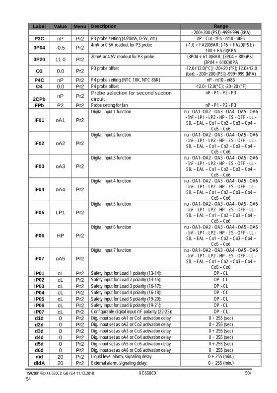
1592001430 XC650CX GB r3.4 11.12.2018 XC650CX 50/54
Label Value Menu Description Range - 200÷200 (PSI) -999÷999 (kPA)
P3C nP Pr2 P3 probe setting (4/20mA, 0-5V, ntc) nP - Cur - tEn - nt10 - nt86
3P04 -0.5 Pr2 4mA or 0.5V readout for P3 probe (-1.0 ÷ FA20)BAR; (-15 ÷ FA20)PSI; (-100 ÷ FA20)KPA
3P20 11.0 Pr2 20mA or 4.5V readout for P3 probe (3P04 ÷ 61.0)BAR; (3P04 ÷ 885)PSI; (3P04 ÷ 6100)KPA
O3 0.0 Pr2 P3 probe offset -12.0÷12.0(°C); -20÷20 (°F); 12.0÷12.0 (bar); - 200÷200 (PSI) -999÷999 (kPA)
P4C nP Pr2 P4 probe setting (NTC 10K, NTC 86K) nP - nt10 - nt86 O4 0.0 Pr2 P4 probe offset -12.0÷12.0(°C); -20÷20 (°F)
2CPb nP Pr2 Probe selection for second suction circuit
nP - P1 - P2 - P3
FPb P2 Pr2 Probe setting for fan nP - P1 - P2 - P3
iF01 oA1 Pr2
Digital input 1 function nu - OA1- OA2 - OA3 - OA4 - OA5 - OA6 - InF - LP1 - LP2 - HP - ES - OFF - LL - SIL – EAL – Co1 – Co2 – Co3 – Co4 –
Co5 – Co6
iF02 oA2 Pr2
Digital input 2 function nu - OA1- OA2 - OA3 - OA4 - OA5 - OA6 - InF - LP1 - LP2 - HP - ES - OFF - LL - SIL – EAL – Co1 – Co2 – Co3 – Co4 –
Co5 – Co6
iF03 oA3 Pr2
Digital input 3 function nu - OA1- OA2 - OA3 - OA4 - OA5 - OA6 - InF - LP1 - LP2 - HP - ES - OFF - LL - SIL – EAL – Co1 – Co2 – Co3 – Co4 –
Co5 – Co6
iF04 oA4 Pr2
Digital input 4 function nu - OA1- OA2 - OA3 - OA4 - OA5 - OA6 - InF - LP1 - LP2 - HP - ES - OFF - LL - SIL – EAL – Co1 – Co2 – Co3 – Co4 –
Co5 – Co6
iF05 LP1 Pr2
Digital input 5 function nu - OA1- OA2 - OA3 - OA4 - OA5 - OA6 - InF - LP1 - LP2 - HP - ES - OFF - LL - SIL – EAL – Co1 – Co2 – Co3 – Co4 –
Co5 – Co6
iF06 HP Pr2
Digital input 6 function nu - OA1- OA2 - OA3 - OA4 - OA5 - OA6 - InF - LP1 - LP2 - HP - ES - OFF - LL - SIL – EAL – Co1 – Co2 – Co3 – Co4 –
Co5 – Co6
iF07 oA5 Pr2 Digital input 7 function nu - OA1- OA2 - OA3 - OA4 - OA5 - OA6
- InF - LP1 - LP2 - HP - ES - OFF - LL - SIL – EAL – Co1 – Co2 – Co3 – Co4 –
Co5 – Co6 iP01 cL Pr2 Safety input for Load 1 polarity (13-14): OP - CL iP02 cL Pr2 Safety input for Load 2 polarity (13-15): OP - CL iP03 cL Pr2 Safety input for Load 3 polarity (16-17): OP - CL iP04 cL Pr2 Safety input for Load 4 polarity (16-18): OP - CL iP05 cL Pr2 Safety input for Load 5 polarity (19-20): OP - CL iP06 cL Pr2 Safety input for Load 6 polarity (19-21): OP - CL iP07 cL Pr2 Configurable digital input i1F polarity (22-23): OP - CL d1d 0 Pr2 Dig. input set as oA1 or Co1 activation delay 0 ÷ 255 (sec) d2d 0 Pr2 Dig. input set as oA2 or Co2 activation delay 0 ÷ 255 (sec) d3d 0 Pr2 Dig. input set as oA3 or Co3 activation delay 0 ÷ 255 (sec) d4d 0 Pr2 Dig. input set as oA4 or Co4 activation delay 0 ÷ 255 (sec) d5d 0 Pr2 Dig. input set as oA5 or Co5 activation delay 0 ÷ 255 (sec) d6d 0 Pr2 Dig. input set as oA6 or Co6 activation delay 0 ÷ 255 (sec) did 20 Pr2 Liquid level alarm, signaling delay 0 ÷ 255 (min.)
didA 20 Pr2 External alarm, signaling delay: 0 ÷ 255 (min.)
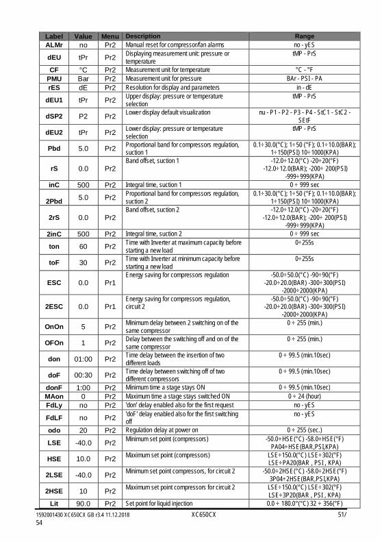
1592001430 XC650CX GB r3.4 11.12.2018 XC650CX 51/54
Label Value Menu Description Range ALMr no Pr2 Manual reset for compressor/fan alarms no - yES
dEU tPr Pr2 Displaying measurement unit: pressure or temperature
tMP - PrS
CF °C Pr2 Measurement unit for temperature °C - °F PMU Bar Pr2 Measurement unit for pressure BAr - PSI - PA rES dE Pr2 Resolution for display and parameters in - dE
dEU1 tPr Pr2 Upper display: pressure or temperature selection
tMP - PrS
dSP2 P2 Pr2 Lower display default visualization nu - P1 - P2 - P3 - P4 - StC1 - StC2 - SEtF
dEU2 tPr Pr2 Lower display: pressure or temperature selection
tMP - PrS
Pbd 5.0 Pr2 Proportional band for compressors regulation, suction 1
0.1÷30.0(°C); 1÷50 (°F); 0.1÷10.0(BAR); 1÷150(PSI) 10÷1000(KPA)
rS 0.0 Pr2 Band offset, suction 1 -12.0÷12.0(°C) -20÷20(°F)
-12.0÷12.0(BAR); -200÷ 200(PSI) -999÷999(KPA)
inC 500 Pr2 Integral time, suction 1 0 ÷ 999 sec
2Pbd 5.0 Pr2 Proportional band for compressors regulation, suction 2
0.1÷30.0(°C); 1÷50 (°F); 0.1÷10.0(BAR); 1÷150(PSI) 10÷1000(KPA)
2rS 0.0 Pr2 Band offset, suction 2 -12.0÷12.0(°C) -20÷20(°F)
-12.0÷12.0(BAR); -200÷ 200(PSI) -999÷999(KPA)
2inC 500 Pr2 Integral time, suction 2 0 ÷ 999 sec
ton 60 Pr2 Time with Inverter at maximum capacity before starting a new load
0÷255s
toF 30 Pr2 Time with Inverter at minimum capacity before starting a new load
0÷255s
ESC 0.0 Pr1 Energy saving for compressors regulation -50.0÷50.0(°C) -90÷90(°F)
-20.0÷20.0(BAR) -300÷300(PSI) -2000÷2000(KPA)
2ESC 0.0 Pr1 Energy saving for compressors regulation, circuit 2
-50.0÷50.0(°C) -90÷90(°F) -20.0÷20.0(BAR) -300÷300(PSI)
-2000÷2000(KPA)
OnOn 5 Pr2 Minimum delay between 2 switching on of the same compressor
0 ÷ 255 (min.)
OFOn 1 Pr2 Delay between the switching off and on of the same compressor
0 ÷ 255 (min.)
don 01:00 Pr2 Time delay between the insertion of two different loads
0 ÷ 99.5 (min.10sec)
doF 00:30 Pr2 Time delay between switching off of two different compressors
0 ÷ 99.5 (min.10sec)
donF 1:00 Pr2 Minimum time a stage stays ON 0 ÷ 99.5 (min.10sec) MAon 0 Pr2 Maximum time a stage stays switched ON 0 ÷ 24 (hour) FdLy no Pr2 'don' delay enabled also for the first request no - yES
FdLF no Pr2 'doF' delay enabled also for the first switching off
no - yES
odo 20 Pr2 Regulation delay at power on 0 ÷ 255 (sec.)
LSE -40.0 Pr2 Minimum set point (compressors) -50.0÷HSE(°C) -58.0÷HSE(°F) PA04÷HSE(BAR,PSI,KPA)
HSE 10.0 Pr2 Maximum set point (compressors) LSE÷150.0(°C) LSE÷302(°F) LSE÷PA20(BAR , PSI , KPA)
2LSE -40.0 Pr2 Minimum set point compressors, for circuit 2 -50.0÷2HSE(°C) -58.0÷2HSE(°F) 3P04÷2HSE(BAR,PSI,KPA)
2HSE 10 Pr2 Maximum set point compressors for circuit 2 LSE÷150.0(°C) LSE÷302(°F) LSE÷3P20(BAR , PSI , KPA)
Lit 90.0 Pr2 Set point for liquid injection 0.0 ÷ 180.0°(°C) 32 ÷ 356(°F)
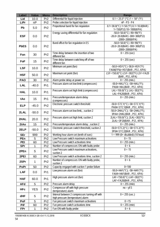
1592001430 XC650CX GB r3.4 11.12.2018 XC650CX 52/54
Label Value Menu Description Range Lid 10.0 Pr2 Differential for liquid injection 0.1 ÷ 25.5° (°C) 1 ÷ 50° (°F) LiPr nP Pr2 Probe selection for liquid injection nP - P3 - P4
Pb 5.0 Pr2 Proportional band for fan regulation 0.1÷30.0(°C) 1÷50 (°F) 0.1÷10.0(BAR) 1÷150(PSI) 10÷1000(KPA)
ESF 0.0 Pr2 Energy saving differential for fan regulation -50.0÷50.0(°C) -90÷90(°F)
-20.0÷20.0(BAR) -300÷300(PSI) -2000÷2000(KPA)
PbES 0.0 Pr2 Band offset for fan regulation in ES -50.0÷50.0(°C) -90÷90(°F)
-20.0÷20.0(BAR) -300÷300(PSI) -2000÷2000(KPA)
Fon 30 Pr2 Time delay between the insertion of two different fan
0 ÷ 255 (sec)
FoF 15 Pr2 Time delay between switching off of two different fan
0 ÷ 255 (sec)
LSF 10.0 Pr2 Minimum set point (fan) -50.0÷HSF(°C) -58.0÷HSF(°F) FA04(FPb)÷HSF(BAR , PSI , KPA)
HSF 50.0 Pr2 Maximum set point (fan) LSF÷150.0(°C) LSF÷302(°F) LSF÷FA20 (BAR , PSI , KPA)
PAO 30 Pr2 Alarm probe delay at power on 0 ÷ 255 (min.)
LAL -40.0 Pr1 Pressure alarm set low limit (compressors) -50.0÷HAL(°C); -58÷HAL(°F); PA04÷HAL(BAR , PSI , KPA)
HAL 10.0 Pr1 Pressure alarm set high limit (compressors) LAL÷150.0(°C); LAL÷302(°F); LAL÷PA20(BAR , PSI , KPA)
tAo 15 Pr1 Pressure/temperature alarm delay (compressors)
0 ÷ 255 (min.)
ELP -45.0 Pr2 Electronic pressure switch threshold -50.0÷STC1(°C) -58÷STC1(°F) PA04÷STC1(BAR , PSI , KPA)
2LAL -50.0 Pr2 Pressure alarm set low limit, , suction 2 -50.0÷2HAL(°C); -58÷2HAL(°F); 3PA4÷2HAL(BAR , PSI , KPA)
2HAL 20.0 Pr2 Pressure alarm set high limit, suction 2 2LAL÷150.0(°C); 2LAL÷302(°F); 2LAL÷3P20(BAR , PSI , KPA)
2tAo 15 Pr2 Pressure/temperature alarm delay , suction 2 0 ÷ 255 (min.)
2ELP -50.0 Pr2 Electronic pressure switch threshold, suction 2 -50.0÷STC2(°C) -58÷STC2(°F) 3P04÷STC2(BAR , PSI , KPA)
SEr 999 Pr2 Working hour alarm set (tenth of ours) 1 ÷ 999 (0= disabled) (10 hour) PEn 5 Pr2 Low Pressure switch maximum activations 0 ÷ 15 PEI 60 Pr2 Low Pressure switch activations time 0 ÷ 255 (min.) SPr 1 Pr2 Number of compressors ON with faulty probe 0 ÷ 6
2PEn 5 Pr2 Low Pressure switch maximum activations, suction 2
0 ÷ 15
2PEI 60 Pr2 Low Pressure switch activations time, suction 2 0 ÷ 255 (min.)
2SPr 1 Pr2 Number of compressors ON with faulty probe, suction 2
0 ÷ 6
PoPr 50 Pr2 Capacity engaged with suction 1 probe failure 0÷100
LAF 0.0 Pr1 Low pressure alarm set (fan) -50.0÷HAF(°C); -58÷HAF(°F); FA04÷HAF(BAR , PSI , KPA)
HAF 60.0 Pr1 High pressure alarm set (fan) LAF÷150.0(°C) LAF÷302(°F) LAF÷FA20(BAR , PSI , KPA)
AFd 5 Pr2 Pressure alarm delay 0 ÷ 255 (min)
HFc YES Pr2 Compressor off with high pressure (temperature) alarm
no – yES
dHF 5 Pr2 Interval between 2 compressors turning off with high pressure (temperature) alarm
0 ÷ 255 (sec.)
PnF 5 Pr2 Fan pressure switch maximum activations 0 ÷15 PiF 60 Pr2 Fan pressure switch activations time 0 ÷ 255 (min) FPr 1 Pr2 Fan ON with faulty probe 0 ÷ 6
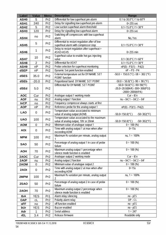
1592001430 XC650CX GB r3.4 11.12.2018 XC650CX 53/54
Label Value Menu Description Range ASH0 5 Pr2 Differential for low superheat pre-alarm 0.1 to 30.0°C/ 1 to 60°F ASH1 240 Pr2 Delay for signalling low superheat pre-alarm 0÷255 sec ASH2 5 Pr2 Low suction superheat alarm threshold 0.1÷15.0°C/ 1÷30°F ASH3 120 Pr2 Delay for signalling low superheat alarm 0÷255 sec
ASH4 no Pr2 Switching off compressors with low superheat alarm No, Yes
ASH5 5 Pr2 Differential to restart regulation after of low superheat alarm with compressor stop 0.1÷15.0°C/ 1÷30°F
ASH6 1 Pr2 Delay to restart regulation after superheat > ASH2+ASH5 0÷255 min
ASH7 10 Pr2 Superheat value to enable hot gas injecting valve 0.1÷30.0°C/ 1÷60°F
ASH8 2 Pr2 Differential for ASH7 0.1÷15.0°C/ 1÷30°F ASH9 nP Pr2 Probe selection for superheat monitoring nP(0) - P3(1) - P4(2) dSEP nP Pr2 Dynamic Set point function enabled nP – P3 - P4
dSES 35.0 Pr2 External temperature set for DYNAMIC SET POINT function
-50.0 ÷ 150.0 (°C) -58 ÷ 302 (°F)
dSEb -20.0 Pr2 Proportional band DYNAMIC SET POINT -50.0 ÷ 50.0(°C) -90 ÷ 90 (°F)
dSEd 5.0 Pr2 Differential for DYNAMIC SET POINT -50.0÷50.0(°C) -90÷90(°F)
-20.0÷20.0(BAR) -300÷300(PSI) -2000÷2000(KPA)
AOC Cur Pr2 Analogue output 1 working mode Cur – tEn AOF nu Pr2 Analog output 1 function nu – InC1 – InC2 – InF InCP no Pr2 Frequency compressor always starts at first
AOP nP Pr2 Reference probe for the analog output 1 nP(0) - P3(1) - P4(2)
LAO 0 Pr2 Temperature value associated to minimum value of analog output (AOM) -50.0÷150.0(°C) -58÷302(°F)
UAO 100 Pr2 Temperature value associated to the maximum value of analog output, 10V or 20mA -50.0÷150.0(°C) -58÷302(°F)
AOM 0 Pr2 Minimum value of analogue output 1 0 ÷ 100 (%)
AOt 0 Pr2 Time with analog output 1 at max when after exceeding AOM
0÷15s
MPM 100 Pr2 Maximum % variation per minute, analog output 1
nu, 1 ÷ 100%
SAO 50 Pr2 Percentage of analog output 1 in case of probe failure
0 ÷ 100 (%)
AOH 70 Pr2 Maximum analog output 1 percentage when silence mode function is enabled
0 ÷ 100 (%)
2AOC Cur Pr2 Analogue output 2 working mode Cur – tEn 2AOF nu Pr2 Analog output 2 function nu – InC1 – InC2 – InF 2AOM 0 Pr2 Minimum value of analogue output 2 0 ÷ 100 (%)
2AOt 0 Pr2 Time with analog output 2 at max when after exceeding AOM
0÷15s
2MPM 100 Pr2 Maximum % variation per minute, analog output 2
nu, 1 ÷ 100%
2SAO 50 Pr2 Percentage of analog output 2 in case of probe failure
0 ÷ 100 (%)
2AOH 70 Pr2 Maximum analog output 2 percentage when silence mode function is enabled
0 ÷ 100 (%)
tbA YES Pr1 Alarm relay silencing no - yES OAP cL Pr2 Polarity alarm relay OP - CL oFF no Pr2 off function enabled no - yES bUr YES Pr2 Buzzer enabled no - yES Adr 1 Pr2 Serial address 1 ÷ 247 rEL 3.4 Pr2 Release firmware Readable only
1592001430 XC650CX GB r3.4 11.12.2018 XC650CX 54/54
Label Value Menu Description Range Ptb - Pr2 Parameter table code Readable only Pr2 - Pr1 Pr2 access Readable only