Embed Size (px)
Citation preview
DATA SHEET
PHO TOGRAPH
W LEVEL THIS SHEET
19 INVENTORY
1 . ~ DOCUMENT IDENTIFICArION
XAppioved for publ'c rclk.):,;Distribution Unlimt.td
per telecon w/Betty Fox (UNA Tech Libr, Chief), the
classified references contained herein may remain.
- -0, 5 3 n kro -_ O" ii-
NTIS GR&1I
DDC TABUnaunc1Oultl edJustification
By______________
Availability Cod"S fAvail and/or SEC'
DISTRIBUTION STAMP DATE ACCESSIONED
DATE RECEIVED IN DDC
PHOTOGRAPH THiS COPY

Wiwi FU(22%
UNS~ IUJCopy No. -- ' A .
LR0710 E of the4?' DEFENSE NUCLEAR
AGENCYUPSHOT=KNOTHOL AG1'1974
NEVADA PROVING R0Ot
March-June 1953
Project 3.5
TESTS ON THE RESPONSE OF WALL AND ROOFPANELS AND THE TRANSMISSION OF LOADTO SUPPORTING STRUCTURE0
I~as
Approved for publi'c release;Distribution unlimited.---------d
HEADQUJARTERS FIELD COMMAND, ARMED FORCES SPECIAL WEAPONS PROJECT
SANDIA BASE, ALBUOUERQUE, NEW MEXICO
'79-
08 21- 0-48 _ _ _ _
Reproduced Direct from Manuscript Copy byAEC Technical Information Service
Oak Ridge, Tennessee
Inquiries relative to this report may be made to
Chief, Armed Forces Special Weapons Project
Washington, D. C.
* .! If .
WT-724This document consists of 182 pages
/ No. -- 3 of 270 copies, Series AIOPERATION UPSHOT-KNOTHOLE
Project 3.5
TESTS ON THE RESPONSE OF WALL AND ROOFPANELS AND THE TRANSMISSION OF LOAD
TO SUPPORTING STRUCT ! rCII
REPORT To THE TEST DIRECTO Jwid IL
Eugene Sevin two
WADC-TN-55-10&o/ V "-
Air Materiel Command (,! Vr or public re!easel,Wright-Patterson Air Force Base 661tibdltlon unliinited .---------
Dayton, Ohio
ABSTRACT
This report deals with the pre- and post-test work on the Air ForceStructures Test, Project 3.5 of Operation LSHOT-KNOTHOLE, Tests on theResponse of Wall and Roof Panels. Ten wall and seven roof panels, rep-resenting typical construction practice (e.g., masonry, reinforced con-crete, metal, and wood siding, etc.) were positioned in three overpres-sure regions in Shot 9. Instrumentation consisted of pressure gages,motion picture cameras, and a strain gae system which measured the blastforces transmitted by the panels to the supporting structure.
All but two of the wall panels were destroyed (the three brick wallsshowed a definite gradation of damage from light through severe) and allof the roof panels were at least partially destroyed. The test resultsindicate that, when a wall panel remains intact, the predicted appliedload represents reasonably well the average load transmitted by the panelto the supporting frame. With the exception of the reinforced concretepanel, the walls that failed transmitted only a small percentage of theapplied loading; initial structural failure occurred during the first20 ms or so, and complete failure in 50 to 100 ms.
Peak pressure damage criteria appear to be justified for most of theroof and wall panels tested and, where possible, critical pressures abovewhich failure of the panel is reasonably assured have been deduced. Anattempt is made to correlate the impulse of the transmitted force withthe diffraction impulse of the predicted critical loading for the panelwith the view toward Incorporating the test results into existing build-ing response analyses. According to this scheme, masonry construction(and apparently wood construction of the type tested) will transmit150 per cent of the critical diffraction impulse, while the other light-weight materials tested will transmit only from 20 to 40 per cent of thisimpulse. The force transmitted by most of the roof structures appeared tobe in substantial agreement with the predicted applied loading during thefirst 50 to 100 ms.
The pressure gage located behind the brick wall which failed indi-cated a remarkably slow buildup time for the incoming pressure wave. Fromthis it is inferred that even though a wall fails structurally quite earlyin the loading period, the debris may not clear from the opening until arelatively long time has passed. In such cases, the peak forces in theinterior of a building are expected to be considerably lower that if thewall debris were not present. The effect of wall debris thus may be ofconsiderably greater importance than bad previously been anticipated in
U i ,.L. •. •
3+......
FID~.

reducing the loading on interior equipment, dovnstream vall columns,and trussvork. Comparison, o/ mqsured p~esres -ith predicted load-ings on several of the roofs fdicates that lbdictions are fair to goodin most respects for the Mach reflectioneregion, but are poor In certainrespects for the regular reflection region.
I.I
iii
--- gum I

FOREWORD
This report is one of the reports presenting the results of the78 projects participating in the Military Effects Tests Program ofOperation UPSHOT-KUOTROTE, which included 11 test detonations. Forreaders interested in other pertinent test information, reference ismade to WT-782, Summary Report of the Technical Director, Military Ef-fects Program. This summary report includes the following informationof possible general interest.
a. An over-all description of each detonation, includingyield, height of burst, ground zero location, time ofdetonation, ambient atmospheric conditions at detona-tion, etc., for the 11 shots.
b. Compilation and correlation of all project results onthe basic measuremaents of blast and shock, thermalradiation, and nuclear radiation.
c. Compilation and correlation of the various project re-sults on weapons effects.
d. A summary of each project, including objectives andresults.
e. A complete listing of all reports covering the Mili-tary Effects Tests Program.
UNGLASIF.IED5
S NC I....,.
**, ,
PREFACE
In a letter dated 12 March 1952, the Air Materiel Coinand wasrequested by Air Research & Development Command to submit for testingin Operation UPSHOT/KNOTHOLE existing requirements for a structuresprogram which would be based on the needs of the Air Force fbr TargetAnalysis and Indirect Bomb Damage Assessment information. Within theAir Materiel Command the responsibility for designing and executingsuch a program was delegated to the Special Studies Office, EngineeringBranch of the Installations Division. The requirements which weresubmitted and approved became part of Program Three of the Operationand were designated as Projects 3.1, 3.3, 3.4, 3.5, 3.6, and 3.26.1.Mr. B. :. O'Brien of Special Studies Office was appointed projectofficer and as such coordinated and successfully directed the planningand operation phases of the six projects.
Armour Research Foundation (ARF) of the Illinois Institute ofTechnology was awarded a contract to assist the Special Studies Officein planning and designing the experiments, and in analysis and reportingof test results#. During the period of planning, close liaison wasmaintained with other interested Air Force agencies, particularly thePhysical Vulnerability Division, Directorate of Intelligence, Head-quarters USAF. Many valuable suggestions were contributed by ColonelJohn Weltman, USAF, Lt Col John Ault, USAF, Messrs. R. G. Grassy andS. White, Dr. F. Genevese and others of that Division, and by Mr.Louis A. Nees, Chief of the Engineering Branch, Installations Division,Air Materiel Command.
WN4-- .
Personnel of the Special Studies Office who were intimatelyconnected with the program were Mr. Iic H. Wang. Chief, SpecialStudies, who was the technical and scientific monitor for the AirForce Program, W. Arthur Stansel (now with landing Gear DevelopmentSection Equipment Laboratory, Wright Air Development Center), andMrs. Maisie G. Ridgeway, secretary to Mr. Wang. Other members of theoffice who were associated with the program were Ilssrs. Re N. Birukoff,P. A. Cooley, J. C. Noble, and Lta. T. M. array, and G. A. Pockwell,USAF.
The atomic effects work of the Special Studies Office is now beingperformed by the Blast Effects Research Group, Mechanics Branch,Aeronautical Research Iaboratory, Wright Air Development Center. Thepersonnel of this group are those formerly associated with the SpecialStudies Office.
Most of the introduction section of this report was taken frcmthe preface of the Preliminary Report, Operation UPSHOT-KNOTHOLEproject 3-5 authored by Eric H. Wang ad Bernard S. O'Brien.
''1i
ACKNOWLED WNTS
This report covers the activities of the Armour Research Foundation
in connection with the Air Force Structures Program, Project 3.5, ofOperation UPSHOT-KNOTHOLE. The work reported herein was sponsored by
the Air Research and Development Command, and performed for Air Materiel
Command, Wright-Patterson Air Force Base, Dayton, Ohio, under the terms
of Air Force Contract No. AF33(03 8 )-30 0 29. This program was technically
monitored by the Special Studies Office of Installations Division, AMC.
Personnel who have contributed to this report include: R. L. Cal-
vin, S. J. Fraenkel, K. C. Gandy, H. Himelblau, R. L. Janes, E. L.
McDowell, K. E. McKee, R. W. Sauer, A. Sherman, T. Schiffman, L. A.
Schmidt, E. Sevin, M. R. Smith, A. H. Wiedermann, and T. A. Zaker.
9
~ ~ ~ ~ ~~~~-R- ..s61 I,- ...I......ML _. -
ABSTRACT ............ ............ . 13
PREFACE e.*.....& ..o ........*..........o. * o * 7
ACKNO$JLEDGME1TS o..ea......... *-% ..... ... ... 9
CHAPR 1 INODUCTION o..... . . . .. . . . . 19
1.1 Purpose of Air Force Test Programs , se ... 191.2 Specific Objectives . . ........ . . . . . . 201.3 Responsibilities . . . . . . ...... . . . . . 21
CHAPTE 2 GEIERAL DESCRIPTION OF TEST . * . . . . . . . . .. 23
2.1 Test Items * * * * * • * * * e * e * * o * * 232.2 Instrumentation . .* . . . . . .. . . . . 24
2.2.1 General o * . . * * a *. . ..... . 242.2.2 Photographic Measurements . . . . . . . . . 242.2.3 Time-of-Break Measurements * . * * * o e . 252.2.4 Sensor Measurements(Strain GaW Measurements) 252.2.5 Air Pressure Measurements ......... 262.2.6 Instrument Records ............ 27
2.3 Location of Test Structures . • • • . • • • • .• 27
CHAPTER 3 PRETEST CONSIDERATIONS . . . . . . . .. . . . . . . 34
3.1 Blast Loading and Structural Design . . . . . . . . 343.2 Sensor Design .... . .. .. . .. .. . .. .. 35
CHAP 4 EXPERIMENTAL RESULTS .. . . . • * • o . . . . 36
4.1 Visual Observations ..... .o * • • ...... 36
11
4.1.1 Wall Panel, 3.5ac, 8 in. Brick (4.2 psi
Overpressure) ................ 364.1.2 Wall PaLel, 3.5bf, 8 in. Brick(7.1 psi
Overpressure) .-.............. 364.1.3 Wall Panel, 3.5ce, 8 in. Brick (12 psi
Overpressure), Fig 4.7 . . . . .. . .... 364.1.4 Wall Panel, 3.5ad, Corrugated Steel Siding
Girt (4.2 psi Overpressure), Fig. 4.8 . . . 374.1.5 Wall Panel, 3.5ae, Corrugated Asbestos Board
over Wood Girt (4.2 psi Overpressure), Fig.Fig. 4.9 . ... . . . . .. 37
4.1.6 Wall Panel, 3.5af, Wood Siding (4.2 psiOverpressure), Figs 4.10 and 4.11 . . . . . 37
4.1.7 Wall Panel., 3.5bd, 8 in. Cinder Block(7.1 psi Overpressure), Figs. 4.12 and 4.13 37
4.1.8 Wall Panel, 3.5cc, 8 in. Cinder Block with4 in. Brick Facing (12 psi Overpressure),Figs. 4.14 and 4.15 ............ 38
4.1.9 Wall Panel, 3.5be, 12 in. Cinder Block(7.1 psi Overpressure), Fig. 4.16 . . . . . 38
4.1.10 Wall Panel, 3.5cd, 6 in. Reinforced Concrete(1/4 per cent Steel)(12 psi Overpressure),Fig. 4.17 .. .. .. .. .. .. .. . .. 38
4.1.11 Roof Panel, 3.5aa, Corrugated Asbestos Roof-ing on Wood Trusses (4.2 psi Overpressure),Fig. 4.18 .. . . . . . . . 38
4.1.12 Roof Panel, 3.5ab, Corrugated Steel Roofingon Wood Trusses (4.2 psi Overpressure),Figs. 4.19 and 4.20 . . . .. *. . ... 38
4.1.13 Roof Panel, 3.5ba, Scaled Wood BowstringTruss, Wood Decking, Tar and Gravel Roofing(7.1 psi Overpressure), Figs. 4.21, 4.22,and 4.23 • . . .• 39
4.1.14 Roof Panel, 3.Sb 3-1/2 in. Precast Con-crete Channels on Steel Purlins, Tar andGravel Roofing (7.1 psi Overpressure),Fig. 4.24 .... ............. 39
4.1.15 Roof Panel, 3.5bc, Laminated 2 by 4 in. FlatWood Deck, Tar and Gravel Roofing (7.1 psiOverpressure), Figs. 4.25, 4.26, and 4.27 39
4.1.16 Roof Panel, 3.5ca, 4 in. Reinforced ConcreteSlab, Tar and Gravel Roofing (12 psi Over-pressure), Fig. 4.28 . s * * . .. . .. . . 39
4.1.17 Roof Panel, 3.5cb, Holorib Steel Channelswith Gypsum Fill, Tar and Gravel Roofing(12 psi overpressure), Figs. 4.29 and 4.30 . 39
4.2 Instrumentation Results .............. 404.2.1 Photographic Measurements . . . . . . . . . 404.2.2 Strain Measurement . . . . . . . . . . . . 404.2.3 Time-of-Break Measurements . . . . . . . . . 414.2.4 Air Pressure Measurements . . . . . . . . . 43
12
-- _nArLWrA1;111A 4IliO
CHAPteR 5 DISCUSSION OF RESULTS .. ............. . 72
5.1 Wall Action . ... . . . . .. . . . .. .. 725.1.1 Blast Loading o . . . . .. ... .. 72
5.1..1 Predicted Loads on Walls .. . . . 725.1.1.2 Analysis of Pressure Record from
Wall Panel 3.5ce . . . .. . . . . 725.1.2 Determination of Transmitted Forces . . . . . 745.1.3 Comparison with Predicted Blast Forces . . . 76
5.1.3.1 Introduction . . o . . . . . ... 765.1.3.2 Masonry Walls . o o . . . .. . . . 765.1.3.3 Reinforced Concrete Wall . . . . . 815.1.3.4 Lightweight Covering . . . .. . 82
5.2 Roof Action . . . . . . . . ... . .. . .. 825.2.1 Predicted Loads on Roofs . .... . . .. 825.2.2 Analysis of the Pressure Records . . .. . 83
5.2.2.1 Test Conditions . . . . . 0 . .0. . 835.2.2.2 General Discussion of Records . . . 865.2.2.3 Effects of Roof Breakage . . . . . 905.2.2.4 Local Effects . . . 0 . . 0 .. .. 91
5.2.3 Comparison with Predicted Loadings . . . . . 925.2.4 Transmission of Force . . .. * .. .. .. 94
5.2.4.1 Determination of Transmitted Force 945.2.4.2 Discussion of Roof Behavior o o . . 95
CHAPTER 6 PREDICTION OF WALL AND ROOF FAILURE . . . . . . . . . 106
6.1 Introduction . . . . . . . . . ........ . 1066.2 Walls . o. . .. . . . . ............ a 107
6.2.1 Masonry Wall .. .. ...... .. . . . 1076.2.1.1 Arching Action Theory of Masonry
Wall Behavior . .......... 1076.2.1.2 Computation of Critical Overpressure 110
6.2.2 Lightweight Covering .......... . 1146.2.3 Reinforced Concrete Walls . . .*. . . . . . 1166.2.4 Rear Walls . . . . . . . .. . . . . .. . 117
6.3 Roofs o. .... ..... . .... 0.... 118
6.3.1 Introduction . . .. . . . . . . ..... 1186.3.2 Critical Overpressures . * * . ... . . .. 119
CHAPTER 7 PREDICTION OF TRANSMITTED FCRCE . . o . . o . . . . . 124
7.1 Introduction . . . . . . . . . . . . . o . . . . . . 124
7.2 Forces Transmittedby Walls ...... . . . 1247.3 Forces Transmitted by Roof . . ........... 1257.4 Application . . . .. . . . . . . . . . . . . ... 127
CHApW 8 CONCLUSIONS AND RECOMWNDATIONS o . . . o . . . . . . 129
8.1 Conclusions .. . . . . . . . . . . . ....... 129
8.2 Recommendations .............. .. .... 134
13
..... . . .l i .. .

UNCLASSIFIED MU. _____
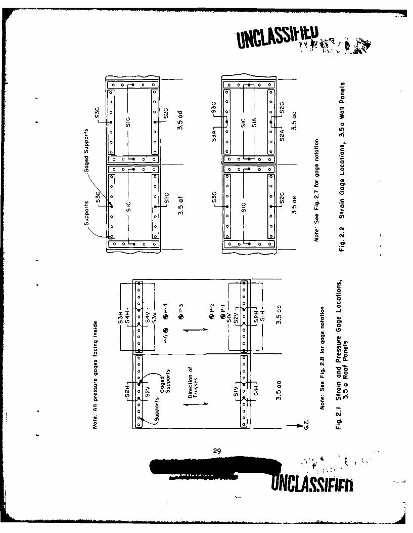
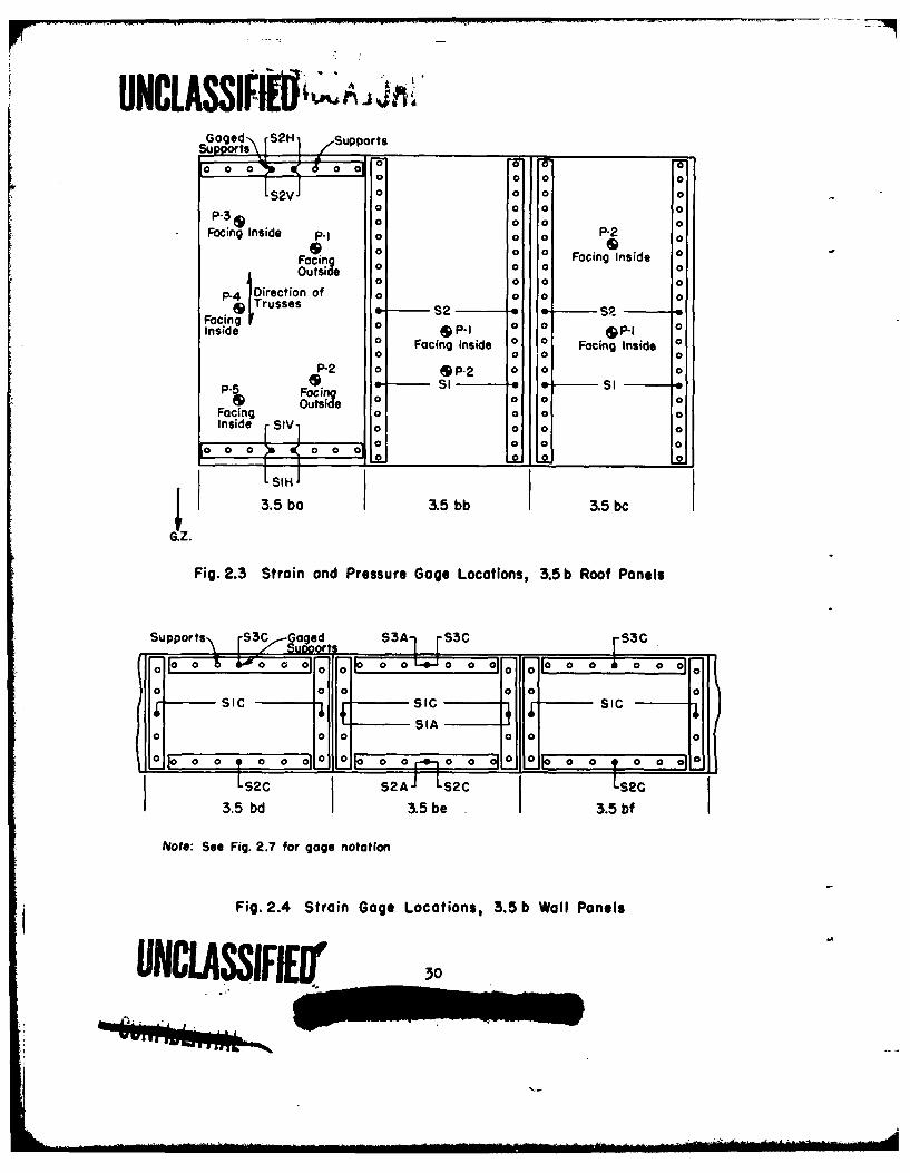
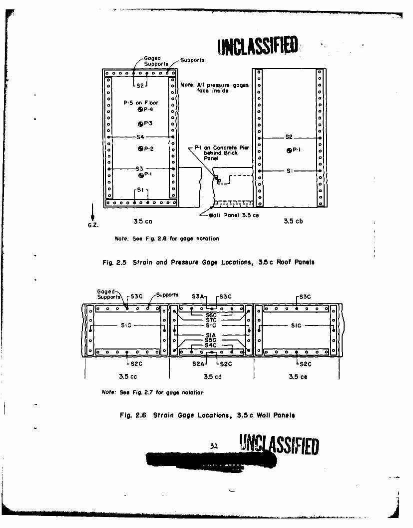
2.1 Strain and Pressure Gage Locations, 3.5a Roof Panels . . . 292.2 Strain Gage Locations., 3.5a Wall Panels . .. . . . . .e 292.3 Strain and Pressure Gage Locations,,3.5b Roof Panels . . . 302.4 Strain Gage Locations, 3.5b Wal Panels . . % ..... 302.5 Strain and Pressure Gage Locations, 3.5c Roof Panels . . . 312.6 Strain Gage Locations, 3*.5c Wall Panels . . .... 12,7 Schematic Design of Wall Sensors ...... 322.8 Schematic Design of Roof Sensors . e •e*0 * * ." 322.9 Typical Wall Sensor Installation (Thrust Bars) . . . . . . 322.10 Location of Structures at Test Site . ......... . 33
4.1 Preshot, 3.5a, Wall Panels .. .. . .. .. . 464.2 Preshot, 3.5a Roof Panels (Visible conduit contains leads
from pressure gages on inside of roof) . ° . . .. . . . 464.3 Preshot, 3.5b, Nall Panels .. .... ....• .* ...... 474.4 Preshot, 3.5b, Roof Panwls Panels . . . . . . . . 484,5 Preshot, 3.50e, Wl1 and Roof Panels S . _. .. 48
4.6 Postshot, 3.6bf, Rear of 8 in. Brick Wall Panel ShowingCenter Crack . .. . . . • . . .. . . . . . . . . . . . . 48
4.7 Postshot, 3.5ce, Damaged 8 in. Brick Wall Panel (Notesimilarity to failure of other masonry panels) . . . . . . 49
4.8 Postshot, 3.5ad, Damaged Corrugated Steel Wall Panel(Individual panels, although bent and twisted, adhered tosteel gif-ts) .. . .. .e e * * * * * * * o * * #• 49
4.9 Movie Film, 3.Sae, Breaking of Corrugated Asbestos BoardWall Panel ..... . . .. ....... . . . . . . . 50
4.10 Preshot, 3.5af, Rear Of Wood Siding Wall Panel . . . . . . 504.11 Postshot, 3-5f, Damaged Wood Siding Wall Panel . . * o o 514.12 Postahot, 3.Sbd, Damaged 8 in. Cinder Block ill Panel . . 514.13 Postahot, 3.Sbd, Edge Blocks Showing Crushing Failure . • 524.14 Postshot, 3.5cc, Damaged 4 in. Brick, 8 in. Cinder Block
Wall Panel • • • • . • * • • • • . • • 0 0 • . . . •. 524.15 Postahot, 3.5cc, Edge Brick and Block Showing Crushing
Failure • . . . .••••••°°•••• * • 534.16 Postshot, 3.Sbe, Damaged 12 In. Cinder Block Wall Panel * 534.17 Postsbot, 3.5cd, Damaged 6 in. Reinforced Concrete Wall
Panel . 0 0 0 * . 0 0 00 0 0 0 a 0 • • 0 • a 0 • a 544.18 Postshot, 3.Saa, Damaged Corrugated Asbestos Board Roofpanel . . .* * . . 544.19 Preshot, 3.05b, Interior of*Corr*ug*ted teel Roof Panel e 554.20 Postshot, 3.Sab, Damaged Corrugated Steel Roof Panel . . . 554.21 Preshot, 3.Sba, Interior of Scaled Bowstring Roof Panel . 564.22 Postahot, 3.-ba, Damaged Bowstring Trusses . . . % . . . 564.23 Postshot, 3.5ba, Interior of Test Cell . . . . . . . . • • 574.24 Postshot, 35.Sbb, Damage to Precast Concrete Channel Roof 6 574.25 Preshot, 3.5bc, Interior of Laminated Wood Roof Panel • * 584.26 Postahot, 3.Sbc, Exterior of Damaged Laminated Wood Roof
Panel 00 0. . 0 .0 00 . . . . . . 58
14
4.27 Postshot, 3.5bc, Interior of Danaged Laminated Wood Roof 59
4.28 Postahot, 3.5ca, Underside of Cracked 4 in. ReinforcedConcrete Roof Panel. .. .. a........ ..... 59
4.29 Preshot, 3.5cb, Steel Channel Roof Panel Shoving SensorSupports and Wire Break Strips ..... .. . . . .* 60
4.30 Postahot, 3.5cb, Damge to Steel Channel Roof Beams . . . 604.31 Installation of Pressure Gage 3.5ce P1 Behind Brick Wal
335ce t R rb.. . . . . . . . . 614.2Lnaie tanRcord 03 5;i*S!X* 624.33 Linearized Strain Record 3.Sab SIV 0 0 * 0 0 0 0 0 0 0 0 634.35 Linearized Strain Record 3.5ab S4H . . . . . . . . . . 634.35 Linearized Strain Record 3.Sab S4V • * 0 0 & 0 0 . 0 0 0 63
4.37 Linearized Strain Record 3.5ac SIC o o a * * * * o e * 644.38 Linearized Strain Record 3.Sac 83C . . . . . 654.39 Linearized Strain Record 3.Sad SIC . o * . . . • • • 654.40 Linearized Strain Record 3.Saf SIC . . . . . ...... 664.41 Linearized Strain Record 3.Sbf SIC . . . . . . . .. .. 664.42 Linearized Strain Record 3o5cd $2C . • ..... . • • • 674.43 Linearized Strain Record 3.5ce 53C . . o o . .. .. . . 674.44 Linearized Pressure Record 3.5ce P1 . .. . . . . . . . . 684.45 Linearized Pressure Record 3.Sab P1 o . . .. . . . . . . 684.46 Linearized Pressure Record 3.Sab P2 . . . .. . . . . . . 694.47 Linearized Pressure Record 3.Sab P3 . . . . .. . . . . . 694.48 Linearized Pressure Record 3.Sab P4 . . . . . . . .. . . 704.49 Linear.ized Pressure Record 3.5ab P5 . . . . .. . . . . . 704.50 Linearized Pressure Record 3.5cb P. . .. . . . . . . . . 71
5.1 Comparison of Predicted Applied and Measured TmamittedForces, Wall Panel 3.5ac (8 in. brick) e * o * .. . . . 97
5.2 Comparison of Predicted Applied and Measured TransmittedForces, Wall Panel 3.5bf (8 in. brick) . .. . . . . . . 97
5.3 Comparison of Predicted Applied and Measured TransmittedForces, Wall Panel 3.5ce (8 in. brick) . . . . . . • • • 98
5.4 Comparison of Predicted Applied and Measured TransmittedForces, Wall Panel 3.Sbd (8 in. cinder block) .. . . . . 98
5.5 Comparison of Predicted Applied and Measured TransmittedForces, Wall Panel 3.Sbe (12 in. cinder block) .. . . . 99
5.6 Comparison of Predicted Applied and Measured TransmittedForces, Wall Panel 3.5cc (8 in. cinder block with 4 in.brick facing) . . . . . . .. . . . . • • 0 0 a 0 0 .• 99
5.7 Comparison of Predicted Applied and Measured TransmittedForces, Wall Panel 3.5cd (6 in. reinforced concrete slab,0.25 per cent steel) ............ .. . .0. . 100
5.8 Comparison of Predicted Applied and Measured TransmittedForce; Wall Panel 3.5ad (Corrugated steel siding oversteel girt) o. .w o . .e .oo* 100
15
-V11 a-
~UNCLASSIPIE
5.9 Comparison of Predicted Applied and Measured TransmittedForces, Wall Panel 3.Sae (Corrugated asbestos board overwood girt) . *. . . .... .. .. .. ... 101
5.10 Comparison of Predicted Applied and Measured TransmittedForces, Wall Panel 3.Saf (Wood siding) . . . . ..... 101
5.11 Comparison of Computed and Measured Response, Wall Panel3.5ac (8 in. brick) . . . . . . . . . . . . . . . . . . 102
5.12 Comparison of Predicted Applied and Measured TransmittedForces, Roof Panel 3.5aa (Corrugated asbestos boards onwood trusses) . . . . . . .. . . . . * . . . . * . . . 102
5.13 Comparison of Predicted Applied and Measured TransmittedForces, Roof Panel 3.5ab (Corrugated steel on woodtrusses) ................... . 103
5.14 Comparison of Predicted Applied and Measured TransmittedForces, Roof Panel 3.5ba (Scaled wood bowstring trusses,wood decking) . . . . . .. . . . . .......... 103
5.15 Comparison of Predicted Applied and Measured TransmittedForces, Roof Panel 3.5bb (3-1/2 in. precast concretechannels on steel purlins) . . . o . o . ... . ... 104
5.16 Comparison of Predicted Applied and Measured TransmittedForces, Roof Panel 3.obc (Laminated 4 in. wood deck) . . 104
5.17 Comparison of Predicted Applied and Measured TransmittedForces, Roof Panel 3.5cb (Holorib steel channels withgypsum fill) . 0 . . .. . .. . . . . . . . .. . .. 105
6.1 Variation of Period with Crushing Strength .. . . . . . 1216.2 Equivalent One-Way Span . . . . . . ...... . 1216.3 Comparison of Arching Theory with MIT Static Test Results
on 8 in. Brick Beams, 8 ft Fixed-End Span . . . .... 1226.4 Comparison of Arching Theory with MIT Static Test Results
on 8 in. Brick Beams, 12 ft Fixed-End Span . . o o . . . 1226.5 Plot of Dimensionless Ratio A(R)/R versus R, Masonry
Wall Analysis * o ... . . . .. . . . . . . . . . . . 1236.6 Critical Impulse Variations with Length . . . . o o o o 123
A.1 Schematic Representation of Arching Action o * . o ... 147A.2 Conditions at Beam Support . ............. 147A.3 Geometric Distribution of Strain Along Contact Area . . 148A.4 Assumed Stress-Strain Relationship for Masonry Materials 149A.5 Assumed Stress-Strain Behavior During Loading Cycle for 149
Masonry Materials ................... 9 * *
A.6 Geometric Distribution of Stress Along Contact Area . • 150A.7 Stress Distribution Along Contact as a Function of
Mid-Span Deflection .. .... .... . ...... 150A.8 Variation of Thrust Force with Beam Deflection . . . . . 151A.9 Variation of Resisting Moment with Beam Deflection . . . 152
B.1 predicted Loading on Flat Roof in Mach Regiony 3.Sbb . . 112B.2 Shock Strength Ratio Versus Percentage of Frontal Open-
ing for Initial Inside Wave Front Near Front Wall . . . i7
16
UNCLASSIFIED

UNCLASSInB.3 Shock Strength Ratio versus Percentage of Frontal Open-
ing for Inside Wave That Strikes Back Wall . . .... 173B.4 overpressure Behind Inside Wall Just Before Strikin Backwall .. . . . . . . . . ... . . 174B.5 Inside Pressure Ratio After Reflection from Inside Backwall .. . . .* .. . . .. . . . 17B.6 Reflection Coefficient and Time to Reach Pseudo Steady
State for Pitched Roofs * 1753.7 Predicted Loading on Pitched Roof in Mach Region, 3.5ab 176B.8 Predicted Loading on Flat Roof in Regular Reflection
Region, 3.5ca ...... . .... • .... . ..... 176B.9 Limiting Angle at Regular Reflection, ext . . . . . . . 177B.10 Predicted Loading on Curved Roof in Mach Region, 3*5ba 9 177
TABLES
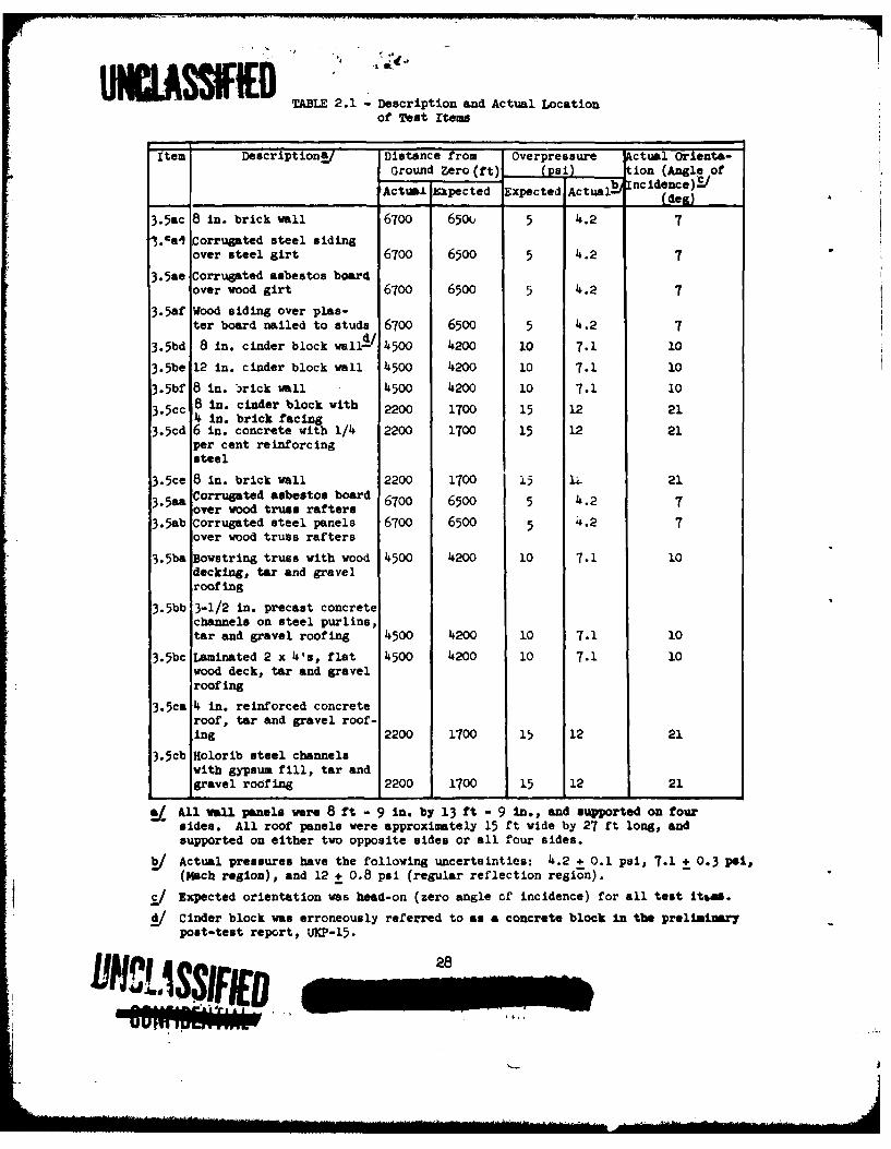
2.1 Description and Actual Location of Test Items . • • . . 28
4.1 Break Time of Wall Panels from Motion Picture Film . . . 414.2 Strain Gage Data Not Used ...... . . . . ..... 424.3 Break Time of Roof Panels * • • • • • a • • * • a • • • 43
5.1 Comparison of Predicted Applied and Transmitted Impulsesfor Wall Panel Which Failed . .... .. .. . . 80
5.2 Pressure Gage Locations on Roofs . . . .... . . . . . 845.3 Failure Observations from Motion Picture Photography for
Pressure Gaged Roofs . . . .e...... • • 855.4 Sumry of Analysis of Pressure Records . . . . . . . . 885.5 Pressure Ranges Used in Analysis of Inside Gage Records 90
B.1 Pertinent Dimensions of Test Panels ...... . . . . 160B.2 Blast Parameters for Test Panels . . . . . ....... 160B.3 Pressure on Front Walls in the Mach Region . . . . . . . 162B.4 Pressure on Front Walls in the Regular Reflection Region 162B.5 Pressure on Outside Surface of Flat Roof in Much Region 164B.6 Pressure on Inside Surface of Flat Roof in Mach Region . 164B.7 Pressure on Outside Surface of Front Half of Pitched and
Curved Roofs in Mach Region .......... . . . . 166B.8 Pressure on Outside Surface of Back Half of Pitched and
Curved Roofs in Mach Region *. . . . . . .* . .. . . 166B.9 Pressure on Inside Surface of Pitched and Curved Roofs
in Mach Region ....... . . .a.. *. 169B.10 Pressure on Outside Surface of Flat Roofs of Structures
in Regular Reflection Region .... * . . . . . .... 169
B.11 Pressure on Inside Surface of Flat Roofs of Structures inRegular Reflection Region ............... 171
17
%UNCLASSIFIED/,
CHAPTM I
INTlRODUCTION
1.1 PURPOSE OF AIR FORCE TEST PROGMWS
The series of tests conducted by the Air Force in Operation UPSROT-KNOTHOLE is part of a continuing Air Force program designated as "Deter-mination of Blast Effects on Buildings and Structures." The United 'StatesAir Force is mainly interested in the offensive aspects of such research.
The UPSHOT-KNOTHOLE projects sponsored by the Air Force and theirspecific objectives cannot be fully understood vithout some knovledge ofthe general objectives of the over-all programe The *esearch resultsemanating from these studies and experiments conducted by the Air Forceare used by a number of government agencies to Improve their own systemsof determining blast effects, or to further their ovn research.
One of these agencies is the Directorate of Intelligence, Head-quarters, USAF, vhich feeds results as they are obtained into Its ownsystem of vulnerability classes, thereby making it possible to analyzeprospective enem targets vith greater accuracy, and to recomend the de-sired ground zero. Another principal user of the research results isthe Strategic Air Comand, vhich applies them tovard improvement of anexisting indirect bomb damage assessment system. The purpose of thissystem is to make it possible to dispense with the usual reconnaissanceafter a strike, using instead information on the actual ground zero,height of burst, and yield of the veapon vhich is brought back to theoperational base by the strike aircraft to determine the damage inflicted.
The task of determining the effect of blast on various types ofbuilding structures and tactical equipment is a rather formidable one,Rovever, its difficulty is somevhat relieved by the fact that, for theoffensive purposes in which the Air Force Is Interested, It is notnecessary to determine the effect of transient loads on thes items iththe same accuracy as vould normally be employed for static design pur-poses. In fact, even if it mere possible to solve the dynamic problemssatisfactorily, Intelligence Information vould be far too sketchy tofurnish the information necessary to justify the use of an accurateanalysis for Items located in prospective enemy countries. From theexperience that is so far available it is expected that It will be
bbNCAUNCLASS ED-wow
UNCAsg~~possible within the foreseeable future to determine blast damage withinbroad limits with sufficient accuracy for planning as well as for oper-ational purposes.
In vie" of the complex phenomena attending shock waves emanatingfrom various types of atomic blasts and the uncertainties inherent indetermining significant parameters, an investigator's first idea wouldbe to obtain solutions through a long series of very elaborate and prop-erly designed full-scale tests. However, neither funds nor time willallow such an approach. It has therefore been the objective of tneagencies involved to obtain sufficiently accurate results by judicioususe of theoretical analyses, laboratory tests, high explosive fieldtests, and a small number of full-scale atomic tests.
Three of these research projects have involved full-scale atomictesting. The first was GREENHOUSE, the second was JANGLE (the first,and so far only, underground burst of an atomic weapon to which an AirForce structures program was subjected) and the third the presentUPSEOT-KKOMTOLE program.
From previous analysis, laboratory tests, and full-scale tests(the latter especially as conducted in NEEMROUSE), methods of damageprediction have been developed by Armour Research Foundation (ARF) andothers. These prediction methods have attempted to describe the char-acter of the blast loads acting on a variety of items. Response compu-tations based on the predicted loadings permit. in turn, an estimate ofphysical damage. However, the relation between the deflection or move-ment of a body and significant military damage has never been clearlyestablished except for extreme cases, e.g., total destruction or nodestruction. Another aim of these tests is, therefore, to establishthe relationship between deflection and functional damage. A full-scaletest also affords an excellent opportunity to determine scaling checkpoints for laboratory tests.
In addition to the scientific aspects of the tests, most of theresults of the Air Force projects can be used by other government agen-cies such as the Directorate of Intelligence to furnish "rough and ready"experimental answers to the behavior of various kinds of structuresunder blast. In many cases there is a statistically significant numberof items involved which, added to previous experimental data such asthose gathered at Hiroshima and Nagasaki,, Vill help round out the pres.ent vulnerability picture. In other cases, mathematical analysis mayhave to rely on ad hoc Information to furnish parameters which cannotbe obtained in a ot-her way.
The foregoing remarks are designed to furnish the background neces-sary for a full understanding of the objectives of this and other of theAir Force projects. The full significance and value of the results ofeach test will be realized only when they are correlated with resultsof past, current, and future analyses, laboratory tests, high explosivefield tests, and full-scale atomic investigations.
1.2 SPECIUIC OCBCTIVES
The response of structures to blast loading is an Important phaseof oer-all target analysis. On@ of the greatest uncertainties in this

• U LASSF--problem from the point of view of analytical treatment'is knowledge ofthe actual forces that serve to distort and damage the structural frameof a building. Load prediction methods have in the past served only toidentify the character of loading acting on the exterior roof and wallpanels. However.* as a result of the action of these components, thisloading is distorted and modified to yield the actual forces that ex-cite the structural frame. In the majority of cases, intelligent en-gineering guesses had to replace factual knowledge in order to incor-porate this factor into response calculations.
The specific objectives of this test are as follows:
1. To determine the percentage of applied load that wallsand roofs transmit to the supporting frames.
2. To determine the modes of failure of various types ofwall and roof panels.
3. To determine as many as possible of the loading changeson the inside of buildings due to the failure of roofsand walls.
4. To determine pressures which will insure damage to typi-cal roof and wall panels which are not amenable to analy-sis at present.
1.3 RESPONSIBILITIES
Armour Research Foundation was retained by the Air Materiel Com-mand (AMC) of the United States Air Force to carry out the followingwork:
1. Consultation on the selection of the test items.2. Design of the test items.3. Specification of instrumentation requirements.4. Location of the structures at the test site.5. Supervision of construction of the test items.6. Theoretical and experimental analyses concerning pretest
predictions of blast loading and response of the testitems where required.
7. Analysis of the test results.8. Submission of reports accounting for the ARF's activities
pursuant to the objectives of the program.
Detailed statements of the duties and obligations of the contractingparties can be found in the Statement of Work in Air Force ContractAF33(038)-30029.
Preparation of coistruction drawings for most of the test itemswas subcontracted by the ARF to the firm of Holabird and Root and Burgee.A member of this organization supervised the actual construction underthe general direction of the ARF. As-built drawings of all the test item
,-UNI-ASMED

UIcLAmw1were prepared by the Silas Mason Company, which was also in charge ofthe construction vork.-
All electronic instrumentation was installed and operated by theBallistic Research Laboratories (BRL) under Project 3.28.1 StructuresInstrumentation, WT-738. The BRL was also responsible for the reduc-tion and presentation of the instrument records. Motion picture photog-raphy was handled by personnel connected with Project 9.1, TechnicalPhotography, WT-T79.
UNCLASSIFIED11
/
CHAPTER 2
GENERAL DESCRIPTION OF TEST
2.1 TEST ITEMS
Ten wall panels and seven roof panels, all but one representingtypical construction practice, were included in Shot 9 at ground rangeswhere the blast was expected to cause major damage or total destructionto most of the items. (One roof, 3.5ba, was a geometrically scaledmodel of a 50 ft span wood bowstring roof designed for 40 paf live load.)The panels were grouped together at three locations, the groups beingdesignated as 3.5a (at 6700 ft) 3o5b (at 4500 ft), and 3.5c (at 2200 ft).The test panels are described briefly in Table 2.1; as-built construc-tion drawings are included in Appendix C of this report, pretest andpostshot photographs are shown in Figs. 4.1 through h.31.
The test wall panels, measuring 8 ft 9 in. high by 13 ft 9 in.wide, were mounted in cells of reinforced concrete construction designedto rigidly withstand the effects of the blast. The cells housing thewall panels each measured approximately 16 ft wide, 10 ft high, and7 ft deep. The rear and side walls of the cell were approximately16 in. thick, and the frontal area facing ground zero was left open toaccommodate the test panel. The front ends of the side alls werenotched in order to house the sensor bars which supported the panel andmeasured the blast loads transmitted by it to the frame. In order toprevent pressure buildup on the back side of the walls, the openingsbetween the frame and wal panel were sealed with 1/ in. steel platesbolted to the concrete (see Fig. .7). In general, all of the testcells at each location were placed adjacent to one another and pouredmonolithically.
In the interests of economy, two groups of test cells (3.5a and3.5b) were attached to silar structures built for Project 3.29(Federal Civil Defense Administration test). It is expected that theresults of this project will be of value to Project 3.29, inasmuch asseveral of the test panels in the latter project were withdrawn be-cause of their similarity to the Project 3.5 panels. Project 3.29panels were much less extensively instrumented than were the 3.5 struc-
tures.
e3
SI HCbLASSNFi U-
IL 'll ll I. . .... . ... . .. ... .. .... .. ..... ... .... .Ih IIII .L ... . lAlS.... . ...; S I- I T D . . .. . .....
The roof panels, each approximately 27 ft long and 15 ft wide,were also supported in test cells of reinforced concrete measuringapproximately 15 ft wide, 10 ft high, and 30 ft deep. The front and
rear malls of these structures each had two openings measuring 3 ftby is ft which comprised about 17 per cent of the gross frontal area.
The purpose of this design was to simulate the loading on roofs of
structures having wall openings (e.g., vindows or doors). The walls
and sides of the test cells were 16 in. thick and were reinforced by
pilasters every 7-1/2 ft. In addition, horizontal bracing was placed
at the top and bottom of the walls. The tops of the walls were notched
in order to accommodate the sensor elements which supported the roof
panel and measured the blast force transmitted by it to the frame.
2.2 IISUMATION
2.2.1 General
The instrumentation provided was designed to meet the follow-ing objectives:
1. To determine the modes of response of the roof and
wall panels i.e., the type and degree of failure.
2. To determine the actual forces transmitted by these
panels to their supporting frames.
3. To determine the pressure distribution on the roofpanels and behind a failing wall.
Objective (1) was to be achieved by means of motion picture
photography and time-of-break measurements; objective (2) was to be
achieved by means of a specially designed force measurement systemutilizing strain gage data. The strain gages were located on so-called
sensor bars which supported the roof and wall panels in the test cells;
objective (3) was to be achieved by means of pressure gage measurementstaken on the roof panels and behind one of the wall panels. No pres-
sure gages were provided on the outside surfaces of the wall paelssince recording channels were at a premium, and it was felt that this
loading could be adequately determined from knowledge of the free stream
pressure-time data provided by other of the UPSHOT-KNOTHOL Projects.
2.2.2 Photographic Measurements
Motion picture photography was provided for each wall and roof
panel at the two farthest ground range locations. Two cameras were in-
stalled at each of these locations, and the film record covered the en-
tire response period of interest. No cameras were provided at the closest
location (3.5c at 2200 feet) since visibility was expected to be practical-ly zero and, in addition, the camera towers probably would have been de-
stroyed by the blast at this distance.
HLASSI lED 2
nus
UNCLASSIFIE '"Bell and Howell Gun Sight Aiming Point Cameras (GSAP) with
special-order Eastman Kodak film (Type 918 Emulsion) were used exclu-sively. Nominal film speed of the cameras was 64 frames per second,although this actually varied from 59 to 66 frames per second. Thecameras were calibrated by observing well-defined shock phenomena re-corded on the film, since no timing marks were provided. More detailedinformation as to the equipment and field layout can be obtained fromProject 9.1, Technical Photography, WT-779.
2.2.3 Time-of-Break Measurements
In order to aid in the study of modes of failure, time-of-breakgages were placed on roof panels 3.5bb, 3.5bc, 3.5ca, and 3.5cb (seeTable 2.1). Two types of break gages were employed. One consisted ofa stretched wire which closed a set of electrical contacts when dis-placed about 1/2 in. from its original position (see Fig. 4.29). Theresulting electrical signal was superimposed upon a highly accurate timebase and recorded on a simplified magnetic tape recorder.
The other type of gage consisted of either aluminum foil stripsor thin wires crisscrossed over the test panel (see Figs. 4.25 and 4.28).Breakage of the strips provided an electrical signal by opening a con-tact. Complete details of these installations are contained in the finalreport on Project 3.28.1, Structures Instrumentation, WT-738.
2.2.14 Sensor Measurements (Strain Gage Measurements)
Special sensing elements were provided in order to measure theforces transmitted by the panels to the supporting frame. These sen-sors were intended not only to permit measurement of the transmittedforces, but to model as closely as possible the actual connection de-tails of the panels. A complete schedule of the sensor instrumentationis shown in Figs. 2.1 through 2.6. The wall and roof sensor designsare shown schematically in Figs. 2.7 and 2.8. An actual wall sensor in-stallation is shown in Fig. 2.9.
The sensor elements were constructed from steel bars of squarecross section spaced equidistantly around the perimeter of the testpanels. The ends of the bars were welded to steel plates, one of whichwas securely bolted to the supporting structure and the other attachedto the test panel. Details of this construction are shown in Appendix C.The forces in the sensor bars were recorded by means of strain gagesconnected so as to yield average direct strains in the bars. The freelength of the sensor bars was made about eight times the cross sectiondimension in order to achieve a uniform stress distribution across thesection at which the strain gages were mounted.
The sensor design provides for the measurement of a thrust force(i.e., a force in the plane of the wall) in addition to the measurementof a direct compressive force. The thrust bars were provided since cur-rent theories concerning wall action indicate that such forces are de-veloped as a result of deformation of the panel.
L NLASSIFIED-l-..'
UNCLASSIFIEDStandard SR4 strain gages were used in four active arm bridge
configurations to measure strain. The output of each bridge was fed intoa Webster-Chicago recording system through a coupling unit and recordedon magnetic tape. The calibration of the strain gages was accomplishedelectrically by shunting the proper arm of each gage installation withan accurately known resistance to simulate actual strain. Complete de-tails of the strain gage installations are contained in the final reporton Project 3.28.1, Structures Instrumentation, WT-738.
2.2.5 Air Pressure Measurements
The primary aim of the pressure measurements was to provide datawhich would aid in evaluating current prediction methods for blast forceson roofs of structures with front and rear wall openings. In particular,data are needed concerning the pressures on inside roof surfaces duringthe time the initial interior shock sweeps down the building and is re-flected back to the front.
Other factors of interest include: (1) the period of time whichelapses before the interior pressure begins to follow the outside freestream pressure decay; (2) whether or not the pressures on the insideroof surface are disturbed seriously by protuberances (such as purlinsand trusswork) on or close to this surface; and (3) whether the pres-sure on the inside roof surface tends to follow closely the pressureson the floor of the building. (In field tests floor pressures are fre-quently easier to measure than inside roof pressures.)
Twenty pressure gages were used for blast loading studies on theroof panels, as shown schematically in Figs. 2.1, 2.3, and 2.5. Seven-teen gages were arranged to record pressures on the inside surfaces ofthe roofs; one was located on the floor beneath a roof, and two were lo-cated to read pressures on the outside of one roof. Six of the sevenroof panels had at least one pressure gage. One additional pressuregage was placed behind a brick wall panel (3.5ce) in an attempt to ob-tain some information as to the change in loading on the inside of astructure as a result of wall failure.
Gages were mounted flush with the surface whenever possible.Typical installations can be seen in Figs. 4.21 and 4.29. Gage cablesfor inside pressure measurements were led through a U-pipe fixed to theoutside of the roof and returned through the roof to the interior about3 ft away from the gage face. This method prevented gage cable connec-tions from creating local and undesired pressure disturbances which couldaffect the gage.
On the corrugated steel roof, 3.5ab, the gages could not bemounted as noted above. A smooth mounting surface was made for thesegages by bolting a plate about 12 in. wide (in the flow direction) andI in. thick against the underside of the corrugated steel roof surface.The gage face was mounted flush with this plate. This method of mount-mng can be seen in Fig. 4.19. Details of the dimensional locations ofthe gages are given in Table 5.2 and in the construction drawings ofAppendix C.
UNCLASSIFIED 26Iuw dONOs .NEW
001 107
ONVLASSIFIED *All air pressure versus time measurements were obtained by the
use of Wiancko type gages, a differential inductance type bridge actuatedby a pressure-sensitive Bourdon tube. The gage output was fed into modi-lied Webster-Chicago magnetic type recorders. The circuitry is describedas a phase modulated system.
Just prior to the test the pressure gages were calibrated stati-cally in conjunction with the recording system. A regulated air pres-sure system was used for positive pressures and a vacuum pump was usedfor negative pressures. Accurately known steps of pressure were appliedin increments of 10 per cent of full-scale deflection for each gage.The resulting record was then played back and a calibration curve estab-lished.
The accuracy of the press 'e values is estimated by the BRL at3 per cent of full-scale readings. The time resolution is in every casewithin 2 ms. Complete details of the pressure gage installations arecontained in WT-738.
2.2.6 Instrument Records
The BEL handled all of the instrumentation with the exceptionof the photographic measurements. The output of the strain and pres-sure gages was recorded initially on magnetic tape, and later playedback onto oscillographic paper. The records in this form exhibit cer-tain undesirable characteristics (e.g., the ordinate scale is markedlynonlinear) which make them ill-suited for purposes of interpretationand comparison. For this reason all the records were subsequently con-verted to linear form.
The BRL reduced, calibrated, and plotted to linear scales allof the instrument records, and also submitted tabulated listings of thepoints, as well as ozalid copies of the original playbacks. The ARFwas responsible for fairing curves through the linearized plotted points.
2.3 LOCATION OF TEST STRUCTURES
The location of the structures at the site is shown in Fig. 2.10.Ground range, actual orientation, and measured overpressures are givenin Table 2.1. Other pertinent information is given in Table B.1. Be-cause of the bombing error in Shot 9, the test structures were not struckhead-on by the blast wave as intended. The actual angle of incidencevaried from about 21 deg at the closest location (3.5c) to only about7 deg at the farthermost location (3.5a). In other respects the testas conducted did not deviate significantly from the test specificationsgiven in Part VII of the final pretest report on Contract No. AF33(038)-30029, Test of Roof and Wall Panels.
UNCLASSIFIED .
wv4wJIH
M ASSFED TABLE 2.1- Description and Actual Location
of Test Items
Item Description!/ Distance from Overpressure ctual Orients-
Ground Zero (ft) (psi) ion (Angle of
ActuL rapected xpected Actuab (ncidence)-/
3.5ac 8 in. brick wall 6700 650U 5 4.2 7
3.ca4 Corrugated steel siding
over steel girt 6700 6500 5 4.2 7
3.5ae Corrugated asbestos boardover wood girt 6700 6500 5 4.2 7
3.5af Wood siding over plas-ter board nailed to studs 6700 6500 5 4.2 7
3.5bd 8 in. cinder block wall d- 4500 4200 10 7.1 10
3.5be 12 in. cinder block wall 4500 4200 10 7.1 10
3.5bf 8 in. ,rick wall 4500 4200 10 7.1 10
3.5cc 8 in. cinder block with 2200 1700 15 12 214 In. brick facing
3.5cd 6 in. concrete with 1/4 2200 1700 15 12 21per cent reinforcingsteel
3.5ce 8 in. brick wall 2200 1700 i5 L. 21
3.Saa Corrugated asbestos board 6700 6500 5 4.2 7over wood truss rafters
3.5ab Corrugated steel panels 6700 6500 5 4.2 7over wood truss rafters
3.Sba Bowstring truss with wood 4500 4200 10 7.1 10decking, tar and gravelroofing
3.5bb 3-1/2 in. precast concretechannels on steel purlins,tar and gravel roofing 4500 4200 10 7.1 10
3.5bc Laminated 2 x 4's, flat 4500 4200 10 7.1 10wood deck, tar and gravelroofing
3.5ca 4 in. reinforced concreteroof, tar and gravel roof-Ing 2200 1700 15 12 21
3.5cb Holorib steel channelswith gypsum fill, tar andgravel roofing 2200 1700 15 12 21
! A ll1 vall panels were 8 ft - 9 in. by 13 ft - 9 in., and supported on foursides. All roof panels were approximately 15 ft wide by 27 ft long, andsupported on either two opposite sides or all four sides.
b Actual pressures have the following uncertainties: 4.2 + 0.1 psi, 7.1 + 0.3 psi,(Mach region), and 12 + 0.8 psi (regular reflection region).
c/ Expected orientation was head-on (zero angle cf incidence) for all test itras.
d/ Cinder block was erroneously referred to as a concrete block in the prelilai.rypost-test report, UKP-15.
28-il
0 0 - 0 0 0 0, 0 0 (
0 0 00
0 0 0 0 o0
N) 0 0 N~ o 1 0 0
14) 0~f 0
0 0 00
0.06 0 0
0 00 0 0
0 ~C0 0 0 r-o0 0 0 0 0 0 00 0 7o
0 0 0 0
US0 0 o ~ 0 2l 0'
0 0 L06 0 0 N 0 0 NN
V~ ) 0~ 0 0d d
0 0(- -oJ
0.00 0
000~ 0 0 00r
0 >
0o 0 0 ?N Z nN
*00
0 00 '0 CL
"00
00' . ' xq
44S0
0 Q6
0 00e
29 ____
1JCASSIrjrnf
UNCLASSIFI *AJ,,j.i#GagedN S21-1 "Supports
Supports_________
o 0 0 0
2-o 0 0 00 0 0 0
P-3 o o oFacing Inside P-I o 0 0 9
4 0 0 0 0Facing InsideOutside 0 0 0 0
0 0 0 0
P-4 IDirection of 0 o 0 o,Trusses - S2
Facing o o oInside & P-I &P- o
o Facing Inside o o Facing Inside 00 0 0 0
P-2 0 I P2 0 0 009 -F SI - - SI .0
do Otsicge 00 0 0P'in 0 0 0
Inside SIVo 0 0 0
o 0 0 0i o oO LO I LO L JoO
JZ. 3.5 ba 3.5 bb 3.5 bc
Fig. 2.3 Strain and Pressure Gage Locations, 3.5b Roof Panels
Supports rS3CGaged S3AI [S3C r-S3C
0 0 0 0 0 0SIC SIC SIC
SIA0 0 0 0 00_o~ ~~~ -oU .o o o,_ ;:;, °° ' ° °- '
1-10 0 ,000 0 0 02 ooilU1. S2C S2A L52C S2C
3.5 bd 3.5 be 3.5bf
Note: See Fig. 2.7 for gage notation
Fig. 2.4 Strain Gage Locations, 3.5 b Wall Panels
UNfCASSIFIEIT 30
Gaged Supports _
Supports
0 0 0 0 4 o 9 0 0 a 0
a0 00 L$21 0 Noe All pressure gages o o0 face inside 0 0
0 0 0 0
0 P-5 on Floor 0 0o *P-4 o0 00 0 0 00 0 0 0a 0- - S4 O. S20 0 0 00 OP-2 I P-I on Concrete Pier
behind Brick 0 o00 Panel0 0
- $3 - .sti -o P- o 0o 0
SI10 _ _P -00 0 0 0
0 S l i 000 0
CO -0--oJ -a - 0j Wall panel 3.5 ce I
3.5 ca 3.5 cbG.Z.
Note: See Fig. 2.8 for gage notation
Fig. 2.5 Strain and Pressure Gage Locations, 3.5 c Roof Panels
Gaged-.Suppo sr3C Worts S3A 1 r3c S3CS6- -i0o S7C /0 0a
SIC SIC sic
SIAo S5C 00 0
S4CI.Jo o ~ o0,l.2o o-C" 0 _o . o
3.5 cc 3.5 cd 3.5 ce
Note: See Fig. 2.7 for gage notation
Fig. 2.6 Strain Gage Locations, 3.5c Wall Panels
31i I SSD
UNCLASSIFIED
0a0
0 6
C
.5.
0 -00id 00
j Co.
00 n
0-.2Oh=
I~CA.A~ C
C 0.%
LASFE 32
An- ".' k,!
UH'LASSIFIED
j%
uz
S °I .1
- I
-a
I I I II UE
SLASS1FIEO
CHA.PTER 3
PRETEST CONSIDERATIONS
3.1 BLAST LOADING AND STRUCTURAL DESIGN
The pretest work was concerned primarily with load predictionmethods for the wall and roof panels in both the conventional Mach andregular reflection regions. The wall loadings pertain to solid panels;the roof loadings take into account partial openings in the front andrear walls. This work is given in detail in the final pretest report,Tests on Roof and Wall Panels, Planning Program for Air Force StructuresTests, and is summarized in Appendix B of this report.
The load prediction methods were utilized to establish (a) thepressure regions in which the desired damage to the test panels wasexpected to occur, and (b) the design of the test cells so that theywould rigidly withstand the effects of the blast. The latter analysisassumed that the wall panels would transmit all their load In the formof an impulse to the structure, and that the mode of response of thecell would be either rigid b'Ddy sliding or overturning. The walls ofthe roof test cells (and roofs of the wall test cells) were assumed toact as simple beams and designed to develop only elastic stresses inbending. Impulse-momentum techniques were also utilized in theseanalyses. While this approach resulted in an extremely conservativedesign (which proved successful during the test), it was considerablymore economical than a design based on static application of twicelthe peak loads.
The wall and roof test panels were intended to be representativeof typical size and construction practice. All of the test panels,with the exception of one, were built accordingly. The Air Force wasinterested in the behavior of curved roofs typical of heavy industrial
/ For design purposes when the dyuamic characteristics of the systemand the loading are not well defined, it is common practice toassume a factor of 2 to account for the effects of suddenly appliedloads. The factor 2 corresponds to the well-known response of asimple undamped elastic system subjected to a suddenly appliedconstant load wherein the system attains the same displacement asif it were statically loaded with twice the force.
34U ICLASSiFIED. *t rfu~ly! t
UNCLASSIFIEDconstruction. In practice such a roof might have bovstring elssesspanning up to 100 feet. It was not practical to incltde a structureof this size in the test, so an attempt was made to construct a scalemodel of this type of roof.
At best, true structural scaling can be done in relatively fewand idealized cases. The major difficulties are concerned with theincompatability of dead weight and inertial scaling, and the uncertaintyof modeling the action of connection details. In the present case,it was decided to scale the wood bowstring roof (3.5b&) geometricallyat a ratio of one-half true size. The scaling pertained principallyto the truss members and certain deviations were made in order to permitthe use of standard lumber sizes. It was hoped that the results of themodel test would serve as an indication of the behavior of the proto-type roof.
No attempt was made in the pretest work to carry out detailedpredictions of the behavior of the test panels based on existing theories.However, the test design was such as to provide information relating tothese theories (e.g., the measurement of suspected thrust forces).
3.2 SENSOR DESIGN
A major portion of the pretest work was concerned with the designof the instrumentation system which would permit measurement of theforces transmitted by the test panels to the supporting structure. Thedesign conditions were the following:
1. The supporting system should permit representative con-nection details for the test panels.
2. The period of vibration of the sensor bars should beappreciably less than that of the test panels in orderto adequately resolve the transmitted forces.
3. The strains in the sensor bare should be large enoughto produce an adequate signal from the strain gages.
4. The sensor bars should be long enough so as to causea uniform strain distribution at the cross sectionwhere the gages were mounted, since adequate protestcalibration w- s impractical.
5. The required recording channels should be held to aminimum.
It is seen that these requirements are not all compatible. Con-ditions (3) and (4) must, of course, be satisfied. However, they bothtend to make the bars more flexible and hence tend to violate condi-tion (2). Conditions (1) and (5) severely limit the arrangement of themeasuring system. Nevertheless, an adequate compromise design was evolvedthat has proved to be quite successful.
35
S'iLASSIFIED
UNCLASSIF E.+
CHAPTER 14
EawIMNTkL RESULTS
4.1 VISUAL OB ERVATIONS
Some failure of all of the test panels occurred, as had beendesired. The behavior of the three unreinforced brick panels wasparticularly gratifying since a definite gradation of damage fromminor through severe through total destruction took place. The follow-ing subsections give a general description of the panel failures.Whenever possible, information obtained from the motion picture filmsis also included. Pre- and postshot photographs are shown in Figs. 4.1through Fig. 4.3i.
4.1.1 Wall Panel, 3.5ac, 8 in-Brick (4.2 psi overpressure)
The panel was still in place and almost completely free ofdamage. Close inspection revealed hairline cracks in several bricksat the center of the panel, in the mortar joints at the bottom of thetop course, and along the diagonals near the corners. No additionalinformation was obtained from the motion picture films.
4.1.2 Wall Panel, 3.5bf, 8 in.Brick (7.1 Psi Overpressure), Fig. 4.6
The panel vas still in place, although some damage was noted.Two center courses of brick were pushed in about 3/4 in. with a generaldishing in all around. Cracks through the joints started in the cornersand progressed at approximately 45 deg toard the center of the panel.
Some indications of failure are visible in the films. Towardthe end of the positive loading period, a crack appeared at the top andsides and seemed to move downward. This line of failure Was observedon films from each of the cameras recording the action.
4.1.3 Wall Panel, 3.5ce, 8 in. Brick (12 psi Overpressure), Fig. 4.7
The panel was blown out with only fringes of the brick remian-Ing. The rear portions of the bricks remaining in place showed evidenceof crushing.
36
U[ASS'IFIO1.. Wall Panel 3.5d Co ted Steel Sidin Ove Sft 01 07#.2 psi OverMressure)., Fig. 4.0
The panel, including the 6 in. channel girt, was blown com-pletely inward. The siding was wrapped around the girt, which in turn Vwas badly bent. The end connections of the girt to the supportingframe also failed. On the right side (viewed from ground zero) thewelded clip angle failed at the wall, while on the left side the boltstying the girt to the clip angle sheared.
The film showed that failure of the steel siding started almostimmediately after shock arrival. The first indication of failure Vasa dishing in of the siding between supports. The individual panelsthen failed and finally the girt was observed to distort and fail.
41..5 Wall Panel, 3.5ae, Corrugated Asbestos Board Over Wood Girt(l4.2 psi Overpressure), Fig. '.9
The siding was blown in and completely shattered, as was the4 by 6 in. wood girt to which the siding was nailed. The wood girt badbeen toe-nailed to its support.
The films showed that individual panels failed by crackingacross the supports and across the center of the panels. Initiallythe lap between adjacent panels remained in place. The lapped sectionsthen failed and the girt failed immediately afterward.
4.1.6 Wall Panel, 3.2!f, Wood Siding (4.2 psi Overpressure),Figs. 4.10 and 4. 11
The wood siding was blown out and completely shattered. Thesupporting studding was completely broken up. The films shoved thatthe wood siding was initially charred by thermal radiation but thesmoke had almost entirely dissipated prior to shock arrival. Subse-quent cracking of the wood was clearly visible against the charredbackground. The wall failed by bending in the long direction withcracks first appearing at the center of the span. The mode of failurewas such that the studs must have failed prior to any visible crack onthe front of the wall.
4.1.7 Wall Panel, 3.5bd, 8 in. Cinder Block (7.1 psi Overpressure),Figs. 4.12 and 4.13
The panel was destroyed. The edge blocks which remained inplace were crushed along all four edges of the panel. From the films,the initial sign of failure appeared to be the formation of a crackacross the top and down the sides. This crack first appeared approxi-mately one block from the edge of the panel. Cracking then occurredwithin this area and failure was brought about by a dishing actionwhich left some blocks hanging onto the edge supports. During thisaction cracks at 45 deg were observed to progress from the cornerstoward the center of the panel.
37
CLASSIR
4.1.8 Wall Panel, 3.5cc, 8 in. Cinder Block with 4 in. Brick Facing(12 psi Overpressure) Figs. 4.14 and 4.17
The panel was completely blown out with only a small amount ofthe brick and concrete block still clinging to the frame. Crushing on
the rear of these blocks was observed.
4.1.9 Wall Panel, 3.5be, 12 in. Cinder Block (7.1 Psi overpressure),Fig. M.16
The panel was completely broken out in a manner identical tothe 8 in. cinder block panel (3.5bd) described above. Evidence ofcrushing of the rear surfaces of the blocks was also observed. Thefilms, too, showed a behavior similar to panel 3.5bd.
4.1.10 Wall Panel, 3.5cd, 6 in. Reinforced Concrete (1/4 per centSteel) (12 psi Overpressure), Fig. 4.17
The wall was blown out bodily and came to rest at the rear wallof the test cell. Cracks from the corner progressing at 45 deg towardthe center were observed. The vertical crack clearly evident inFig. 4.17 indicates that possibly much of the cracking resulted fromimpact with the rear of the test cell.
4.1.ii Roof Panel, 3"5aa, Corrugated Asbestos Roofing on Wood TrussesTii.2 psi verpressure), Fig. 4.1
The asbestos covering was completely shattered. The floor ofthe structure was covered with small fragments of asbestos toward thefront, while the rear was comparatively clear of debris. The asbestoscover on the rear portion of the roof was blown out and was found lyingon the ground just behind the structure. The pieces of asbestos lyingin the rear outside the structure were larger than those found on theinside. The purlins were still in place and, except for one, wereundamaged. The trusses were still in place and probably could havebeen repaired, although the upper and lower chords in the front halfof the trusses had failed.
4.1.12 Roof Panel, 3.5ab, Corrugated Steel Roofing on Wood Trusses(4.2 psi Overpressure), Figs. 4.19 and 4.20
The corrugated steel covering was lifted off the trusses inlarge sections. The covering from the rear portion of the roof was
found lying on the ground just behind the structure, and a portion of
the covering from the front of the roof was found in front of the struc-ture. One section of the roofing remained in place on the front slope
of the roof. The trusses were completely broken and out of place with
more severe damage to the front half. The purlins were all broken andwere found to the rear of the structure.
UIICIASSiFIII.illmllm1
4.1.13 Roof Panel, 3.5ba, Scaled Wood Bowstring TrussWood Decking,Tar and Gravel Roofing (7.1 psi Overpressure), Figs. 4.21,4.22, and 4.23
The roof was completely destroyed. Most of the 2 in. sheathingwas found inside the structure on the floor. Some of the sheathing wasfound intact behind the structure. The trusses were very heavily dam-aged and off their supports. Most severe damage was observed on thefront half of the trusses, where complete failure occurred. The rearhalf of the trusses was less severely damaged with only partial fail-ures to the upper and lower chords.
4.1.14 Roof Panel, 3.5bb, 3-1/2 in. Precast Concrete Channels onSteel Purlins, Tar and Gravel Roofing (7.1 Psi Overpressure),Fig. 4.24
The roof was partially destroyed. The rear half of the channelswas still in place and undamaged. The purlins supporting the front halfof the roof suffered large permanent deformations. The front quarterpurlin had the largest permanent set with approximately 14-1/2 in.deflection which permitted some of the precast sections to fall directlyto the floor. The precast sections on the front portion of the roofnear the side walls, where the purlin deflection was not so great,apparently remained in place long enough to fail partially in shearbefore they dropped to the floor. The end connection of the purlinsdid not fail.
4.1.15 Roof Panel, 3.5bc, Laminated 2 by 4 in. Flat Wood Deck,
Tar and Gravel Roofing (7.1 psi Overpressure), Figs. 4.25,4.26, and 4.27
The roof was still in place, although the front half as heavilydamaged. The maximum deflection at the centerline was slightly over1 ft. This occurred at a point one-quarter of the distance from thefront to the back walls. The damage decreased at points farther fromthe front wall. The rear half of the roof suffered almost no damage.The front half of the roof was lifted upward and forward about 4 in.,coming to rest on the front wall of the structure.
4.1.16 Roof Panel, 3.5ca, 4 in. Reinforced Concrete Slab, Tar andGravel Roofing (l psi Overpressure), Fig. 4.26
The roof was severely cracked and deflected inward a maximum of7 in. at about one-third the distance from the front wall.
4.1.17 Roof Panel, 3.5cb, Holorib Steel Channels with Gypsum Fill,Tar and Gravel Roofing (12 psi Overpressure), Figs. 4.29 and4.30
The roof failed completely. However, the steel channels remainedwhole, despite being wrapped around purlins in the rear-half of .the
39_. ... .. ..
structure. The front channels fell to the floor. The purlins at theone-quarter and one-half points from the front of the structure weredeflected approximately 16 in. each, while the purlin at the three-quarter point was deflected only about 6 in.
4.2 INTR CNU1TATION RESULTS
4.2.1 Photographic Measurements
Films were obtained from each of the 11 motion picture cameras.While the films provided considerable general information, it was notpossible to obtain many quantitative data since dust and smoke inter-ference caused an appreciable loss of clarity. The mode of failure ofthe various wall panels could be observed, but most of the roof actionwas obscured.
An attempt was made to establish the breaking time of the wallpanels from the films. Due to uncertainties in determining such quanti-ties as true camera speed, shock arrival timep and (principally) theframe of the film at which breaking first occurred, the break timesfound in this manner indicate only order of magnitude values. Theprobable error in locating the instant of break on the film is esti-mated to be approximately one frame (i.e., about 16 ms), which, unfortu-nately, is of the order of magnitude of the break time itself. Theresults obtained are listed in Table 4.1. The condition of the filmsprecluded the possibility of determining break times for the roof panels.No cameras were provided for the 3.5c test items.
4.2.2 Strain Measurement
All but 12 of the 69 strain gage channels provided records.Of these, an additional 6 were discarded because they appeared to giveerroneous information. Thus, 74 per cent of the strain instrumentationwas available for analysis. Only the reinforced concrete roof (3.5ca)provided no usable strain data. A breakdown of the remaining 26 per centof the records is shown in Table 4.2.
It is felt that the usable strain gage data are generally ac-ceptable for the purposes of this test. However, it was not possibleto determine a probable error associated with these data since a numberof the linearized gage records were found to require corrections beforethey could be accepted for analysis purposes. In general it was foundnecessary to modify many of these records by comparing them with theoriginal playbacks in order to ascertain whether (1) all significantfeatures of the records had been reproduced, (2) the zero and base linepositions had been chosen properly, and (3) any gross inaccuracies werepresent.
Representative records are shown in Figs. 4.32 through 4.43.
UNCLASSIFIED
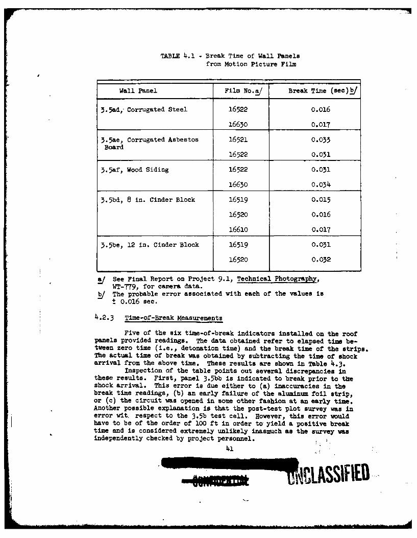
TABLE 4.1 - Break Time of Wall Panelsfrom Motion Picture Film
Wall Panel Film No.!!/ Break Time (sec)_/
3.5ad,- Corrugated Steel 16522 0.016
16630 0.017
3.5ae, Corrugated Asbestos 16521 0.033Board
16522 0.031
3.5af, Wood Siding 16522 0.031
16630 0.034
3.5bd, 8 in. Cinder Block 16519 0.015
16520 0.016
16610 0.017
3.5be, 12 in. Cinder Block 16519 0.031
16520 0.032
See Final Report on Project 9.1, Technical Photography,WT-779, for camera data.
_/ The probable error associated with each of the values ist 0.016 sec.
4.2.3 Time-of-Break Measurements
Five of the six time-of-break indicators installed on the roofpanels provided readings. The data obtained refer to elapsed time be-tween zero time (i.e., detonation time) and the break time of the strips.
The actual time of break was obtained by subtracting the time of shockarrival from the above time. These results are shown in Table 4.3.
Inspection of the table points out several discrepancies inthese results. First, panel 3.5bb is indicated to break prior to theshock arrival. This error is due either to (a) inaccuracies in thebreak time readings, (b) an early failure of the aluminum foil strip,or (c) the circuit was opened in some other fashion at an early time.Another possible explanation is that the post-test plot survey was inerror wit. respect to the 3.5b test cell. However, this error wouldhave to be of the order of 100 ft in order to yield a positive breaktime and is considered extremely unlikely inasmuch as the survey wasindependently checked by project personnel.
41

TABLE 4.2 - Strain Gage Data Not Used
Structure Gage No. Doubtful Data No Data
3-.5ad, Corrugated Steel S3C (1 of 3 gages) XSiding Wall
3.5af, Wood Siding Wall S2C2 XS3CJ 2of3 gages x
3.5bc, Laminated 62 (1 of 2 gages) X2 by 4 in. Wood Roof
3.5be, 12 in. Cinder S 2I X
Block Wall S3AJ 2 of 6 gages X
3.5bf, 8 in. Brick Wall S3C (1 of 3 gages) X
3.5ca, 4 in. Reinforced S1 XConcrete Roof S2 4 of 4 gages X
S3 xs4 x
3.5cd, 6 in. Reinforced SA" xConcrete Wall S3A X
SC 6 of 10 gages X
s1c xS6C Xs~q x
3.5cc, 8 in. Cinder Block SIC (1 of 3 gages) Xwith 4 in. Brick Wall
Total 6 12
Percentages 9% 17%
UNClASSiFIED,
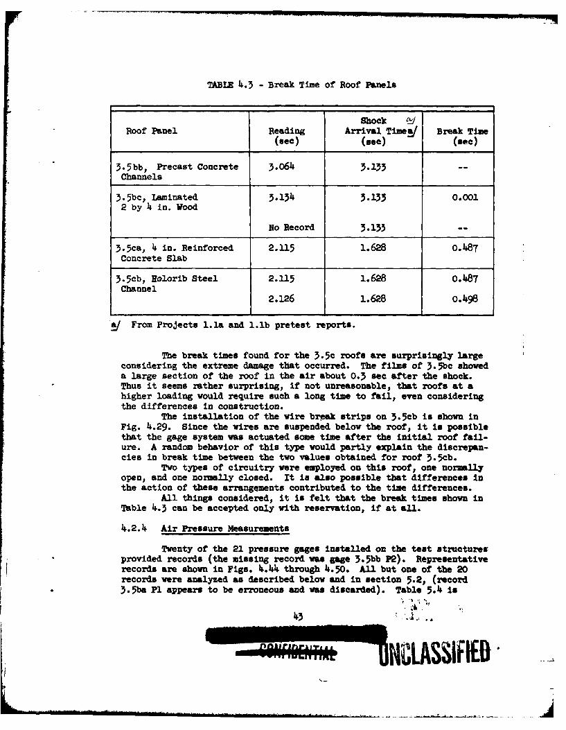
TABLE 4.3 - Break Time of Roof Panels
Shock (L/Roof Panel Reading Arrival Time5/ Break Time
(see) (see) (see)
3-5bb, Precast Concrete 3.06 3.133 --
Channels
3.5bc, Laminated 3.134 3.133 0.0012 by 4 in. Wood
No Record 3.133 --
3.5ca, 4 in. Reinforced 2.115 1.628 0.487Concrete Slab
3-5cb, Holorib Steel 2.115 1.628 0.487Channel
2.126 1.628 o.498
a/ From Projects 1.la and l.lb pretest reports.
The break times found for the 3.5c roofs are surprisingly largeconsidering the extreme damage that occurred. The films of 3. -5bc showeda large section of the roof in the air about 0.3 sec after the shock.Thus it seems rather surprising, if not unreasonable, that roofs at ahigher loading would require such a long time to fail, even consideringthe differences in construction.
The installation of the wire break strips on 3.5cb is shown inFig. 4.29. Since the wires are suspended below the roof, it Is possiblethat the gage system was actuated some time after the initial roof fail-ure. A random behavior of this type would partly explain the discrepan-cies in break time between the two values obtained for roof 3.5cb.
Two types of circuitry were employed on this roof, one normallyopen, and one normally closed. It is also possible that differences inthe action of these arrangements contributed to the time differences.
All things considered, it is felt that the break times shown inTable 4.3 can be accepted only with reservation, if at all.
4.2.4 Air Pressure Measurements
Twenty of the 21 pressure gages installed on the test structuresprovided records (the missing record was gage 3.5bb P2). Representative
records are shown in Figs. 4.44 through 4.50. All but one of the 20records were analyzed as described below and in section 5.2, (record3.5ba P1 appears to be erroneous and was discarded). Table 5.4 is
43
"I1LASSIFIE
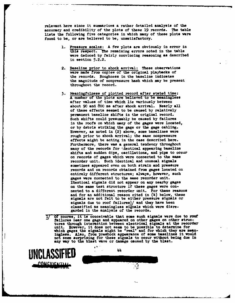
relevant here since it sunnarizes a rather detailed analysis of theaccuracy and credibility of the plots of these 19 records. The tablelists the following five categories in which many of these plots werefound to be, or are believed to be, unsatisfactory.
1. Pressure scales: A few plots are obviously in error inthis respect. The remaining errors noted in the tablewere deduced by fairly convincing reasoning as describedin section 5.2.2.
2. Baseline prior to shock arrival: These observationswere made from copies of the original playbacks ofthe records. Roughness in the baseline indicatesthe magnitude of nonpressure hash which may be presentthroughout the record.
3. Meaningfulness of plotted record after stated time:A number of the plots are believed to be meaninglessafter values of time which lie variously betweenabout 90 and 800 ma after shock arrival. Nearly allof these effects seemed to be caused by relativelypermanent baseline shifts in the original record.Such shifts could presumably be caused by failuresin the roofs on which many of the gages were located,or by debris striking the gage or the gage cabling.However, as noted in (2) above, some baselines wererough prior to shock arrival; the same nonpressureeffects might be acting in the case described here.Furthermore, there was a general tendency throughoutmany of the records for .dentical appearing baselineshifts and sudden dips, oscillations, and pips to occuron records of gages which were connected to the samerecorder unit. Such identical and unusual signalssometimes appeared even on both strain and pressurerecords and on records obtained from gages located onentirely different structures; always, however, suchgages were connected to the same recorder unit.Identical signals did not appear on any nearby gageson the same test structure if these gages were con-nected to a different recorder unit. For these reasonsand for an additional reason cited in (4) below, thesesignals are not felt to be either pressure signals orsignals due to roof failuresl and they have beenclassified as meaningless signals which were disre-garded in the analysis of the records.
y Of course, it is conceivable that some such signals were due to roofailures near one gage and appeared on other gages on other struc-tures through interaction between electrical signals at the recorderunit. However, it does not seem to be possible to determine forwhich gages the signals might be 'Ireal" and for which they are mean-infless. Also, from preshock appearance of some baselines it wouldnot seem surrising for these signals to occur without being due inany way to the blast wave or damage caused by the blast.UNCLASSIFIED
n U£Uzk r
__ln' ,rmjri
a. bjor features of plot which should be ignored: Thiscategory refers to temporary baseline shifts, dips, andpips which appear on the final plots prior to the timesindicated in item (3) above. On the original recordssuch effects tend to correlate between different recordson the basis of the recorder unit used rather than onthe basis of the structure or member on Vhich the ageswere located. Furthermore, where these effects appearedon several different records, the effects generallyoccurred at the same absolute values of time indicatingvelocities of movement between gages far in excess ofany velocities at which pressure disturbances couldtravel here. A number of such dips and pips werecorrectly ignored by the BRL in the reading of therecords during reduction to linear plots.
5. Miscellaneous comments: Entries in this category areself-explanatory in Table 5.1. The majority of theplotted records faithfully correspond to the signifi-cant features of the original records; however, somerecords were read at intervals of time which werequite coarse and, hence, the plots fall to reproducesome significant aspects of the record. This category,of course, does not include nonpressure effects men-tioned in item (I) above.
Despite the difficulties enumerated above, it has been possibleto abstract a considerable amount of information from the 3.5 pressurerecords as described later in section 5.2. Of course, with pressurescales uncertain in many cases, and with the lowered degree of confi-dence in the records resulting from this study of their accuracy, theconclusions which are drawn must often be less definite, or subject tomore doubt, than if the records had been more satisfactory.
UI1~LOSSIFIED -I
Fig. 4.1 Preshot, 3.5a, Well Panels
Fig. 11.2 Preshot, 3.5a, Roof Panels (Visibleconduit contains leads from pressuregages on inside of roof)
IJN'!LSSIFIED 4
Fig. Ie.3 Preshot, 3.5b, Wall Panels
Fig. II.I Preshot, 3.5b, Roof Panels
Fig. 14.5 Preshot, 3.5e, Wall and Roof Panels
Fig. 4.6 Poatshot, 3.5bf, Rear of 8 In. BrickWall Panel Shoving Center Crack
UNCLASSI ff-emw
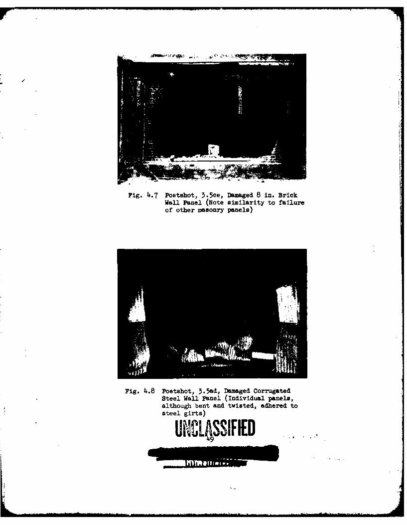
Fig. 4.7 Postahot, 3.5ce, Damaged 8 in. BrickWall Panel (Note similarity to failureof other masonry panels)
Fig. 4.8 Postshot, 3.5&d, Damaged CorrugatedSteel Wall Panel (Individual panels,although bent and twisted, adhered to
steel gifts)
UNCLOSSIFIED
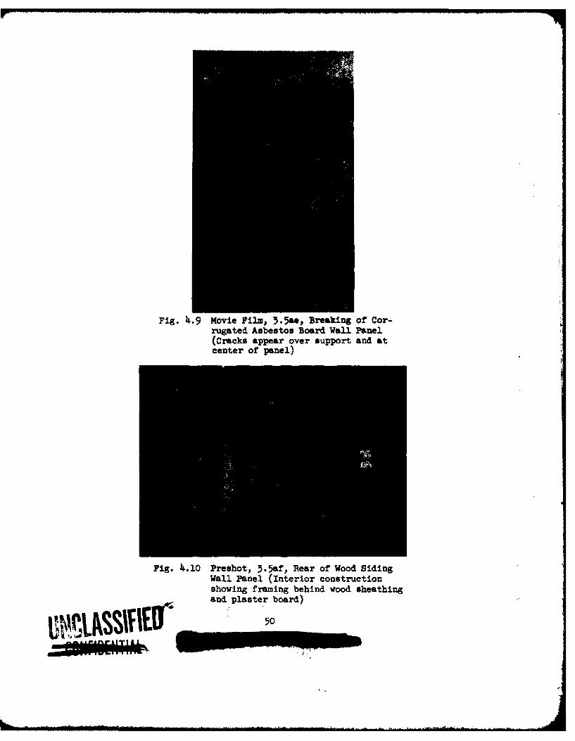
Fig. 4.9 Movie Film, 3.5ae, Breaking of Cor-rugated Asbestos Board Wall Panel(Cracks appear over support and atcenter of panel)
Fig. 4.10 Preshot, 3.5af, Rear of Wood SidingWall Panel (Interior constructionshowing framing behind wood sheathing
and plaster board)
IE50
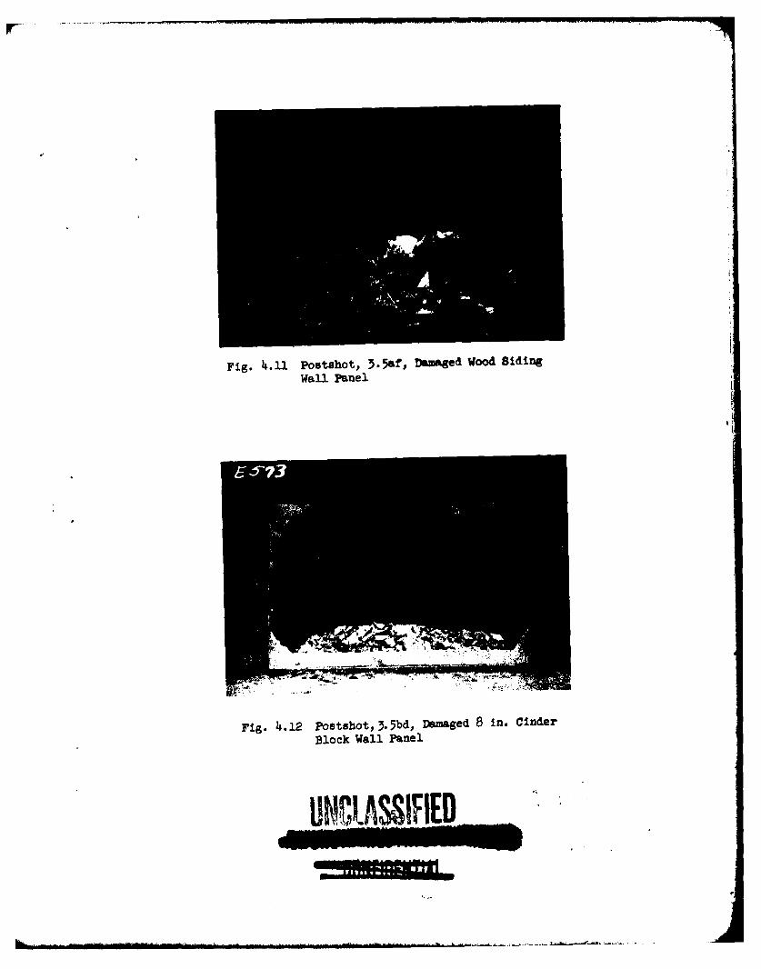
Fig. 4.11 Postshot, 3.5af, Damaged Wood BidingWall Panel
Fig. 4.12 Postshot,3.5bd, Damaged 8 in. Cinder
Block Wall Panel
U~C1ASIFIE
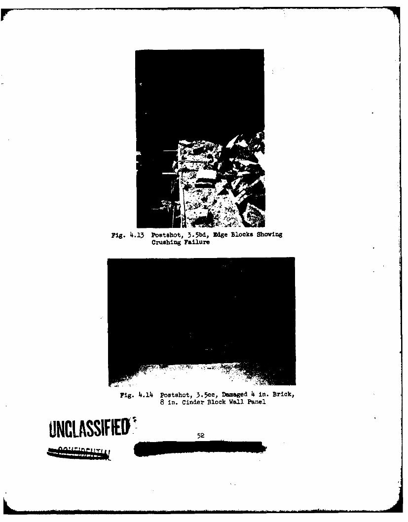
Fig. 4.13 Postshot, 3.5bd, Edge Blocks ShowingCrushing Failure
Fig. 4.14~ Postshot, 3.5cc, Daaged 4 in. Brick,8 in. Cinder Block Wall Panel
UNCLASSIFEI52
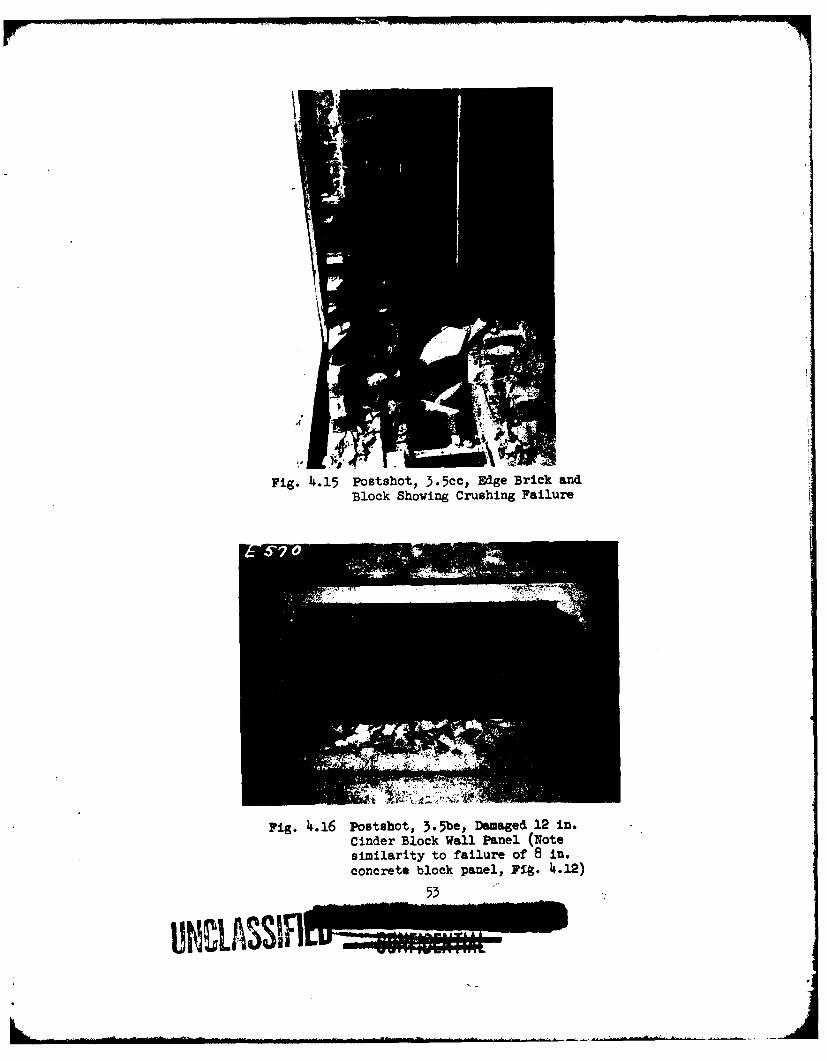
Fig. 4.15 Postshot, 5.5cc, Edge Brick andBlock Showing Crushing Failure
rig. 4~.16 Postshot, 3.5be, Damaged 12 in.Cinder Block Wall Panel (Notesimilarity to failure of 8 in.concrete block panel, Fig. 4.12)
53
UNI~ASS!ILU
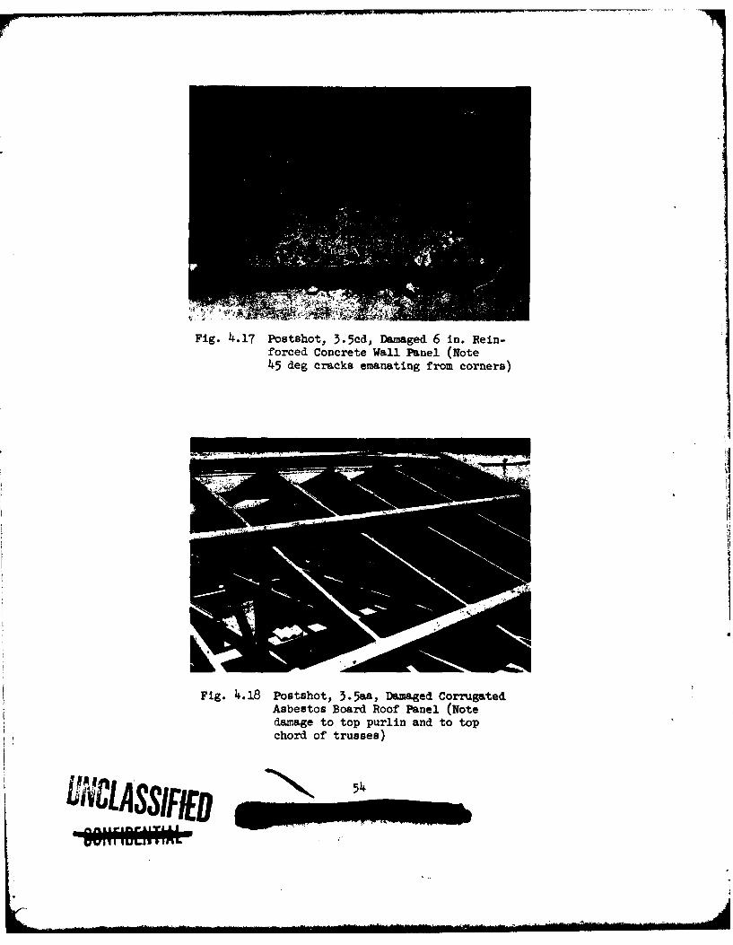
Fig. 4.17 Postshot, 3.5cd, Damaged 6 in. Rein-forced Concrete Wall Panel (Note45 deg cracks emanating from corners)
Fig. 4.18 Postshot, 3.5&&, Damaged CorrugatedAsbestos Board Roof Panel (Notedamage to top purlin and to topchord of trusses)
IICLAS FID 54 _
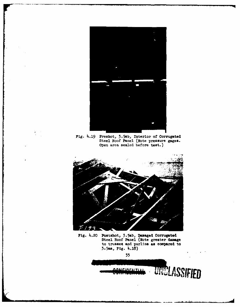
Fig. 4i.19 Preshot, 3.5ab, Interior of CorrugatedSteel Roof Panel (Note pressure gages.Open area sealed before test.)
A.L-
Fig. 4.20 Postshot, 3.5ab, Damaged CorrugatedSteel Roof Panel (Note greater damageto trusses and purlins as compared to3.5aa, Fig. 4.18)
55
~~LAS73IFIED
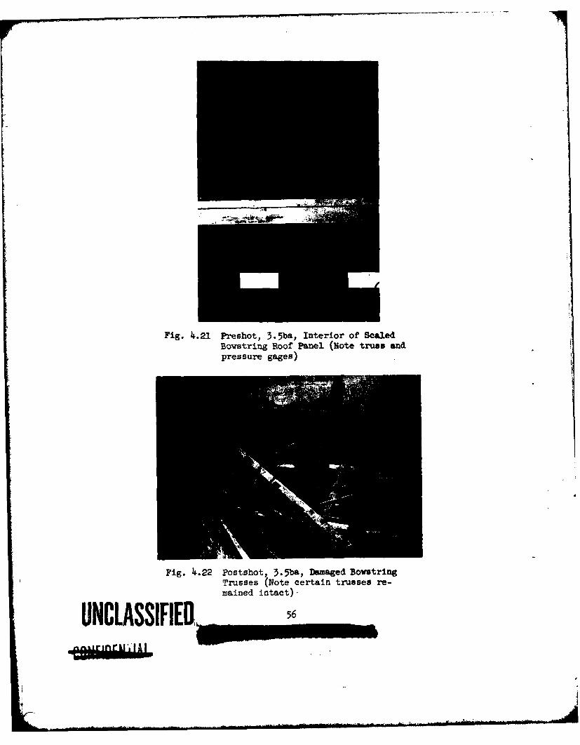
Fig. 4.21 Preshot, 3.5ba, Interior of ScaledBowstring Roof Panel (Note truss andpressure gages)
Fig. 4.22 Postshot, 3.5ba, Damiaged BovstringTrusses (Note certain trusses re-mained intact).
UNAASSIFIED,palgnr LA
Fig. I4.23 Postshot, 5.5ba, Interior of Test Cell
Fig. 4..24 Postahot, 3.5bb, Damage to PrecastConcrete Channel Roof (note severedamage to purlin nearest blast)
UNCLASSIFIED

Fig. 4i.25 Preshot, 3.5bc, Interior of laminatedWood Roof Panel Showing Aluminum FoilBreak Strip
Fig. 4.26 Postahot, 3.5bc, Exterior of DamagedLaminated Wood Roof Panel
UNCIASSIFIEM m~

Fig. 4.27 Postshot, 3.5bc, Interior of DamagedLaminated Wood Roof Panel (cf similarpreshot view, Fig. 4.25)
Fig. 4.28 Postahot, 3.5ca, Underside of Cracked4 in. Reinforced Concrete Roof Panel(Note aluminum foil break strips)
59
-bj-MIIR
Fig. 4.29 Preshot, 3.5cb, Steel Channel RoofPanel Showing Sensor Supports andWire Break Strips
Fig. 4.30 Poctshot, 3.5cb, Damage to SteelChannel Roof Beams
UNCLASSIFIER.,- 6o
I I ri~ I
Fig. Ii.31 Installation of Pressure Gage 3.5cePlBehind Brick wall 3.5ce
UNCLASSIFIED
200
175
125
210
TOS75
~50-
25
-25.
-500 20 40 60 80 100 120 140 160 IS0 200 20 240 260
TIME (MSEC)
Fig. 4.32 Linearized Strain Record 3.5 ab SIH(For Gage Location See Fig. 2. 1)
200
175-
1252
100-
C275-I.-U)
50-
25
0 20 4060 80 100 120 140 160 190 20220 240260TIME (MSEC)
Fig. 4.33 Linearized Strain Record 3.5ab Sly(For Gage Location See Fig. 2. 1)
UNCLASSIFIED 62__ _ __ _ _ _
---- ....
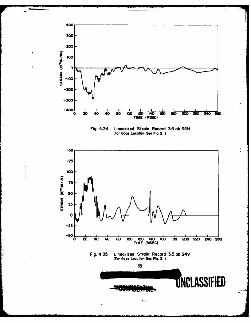
400
300
200-2O
-100
~-loo-
-300
-400 J I J
0 20 40 60 80 100 120 140 160 IK0 220 220 2 M0TIME (MSEC)
Fig. 4.34 Linearized Strain Record 3.5 ob S4H(For Gage Location See Fig. 2.1)
150
125-
100
75
50,
~25-a-
0 -
-25
V
-50) 1 1 I 1 I I I 1 I 1
0 20 40 60 80 100 120 140 160 10 200 220 240 260TIME (MSEC)
Fig. 4.35 Linearized Strain Record 3.5 ob S4V
(For Gage Location See Fig. 2.1)
~UJNCLASSIFIED
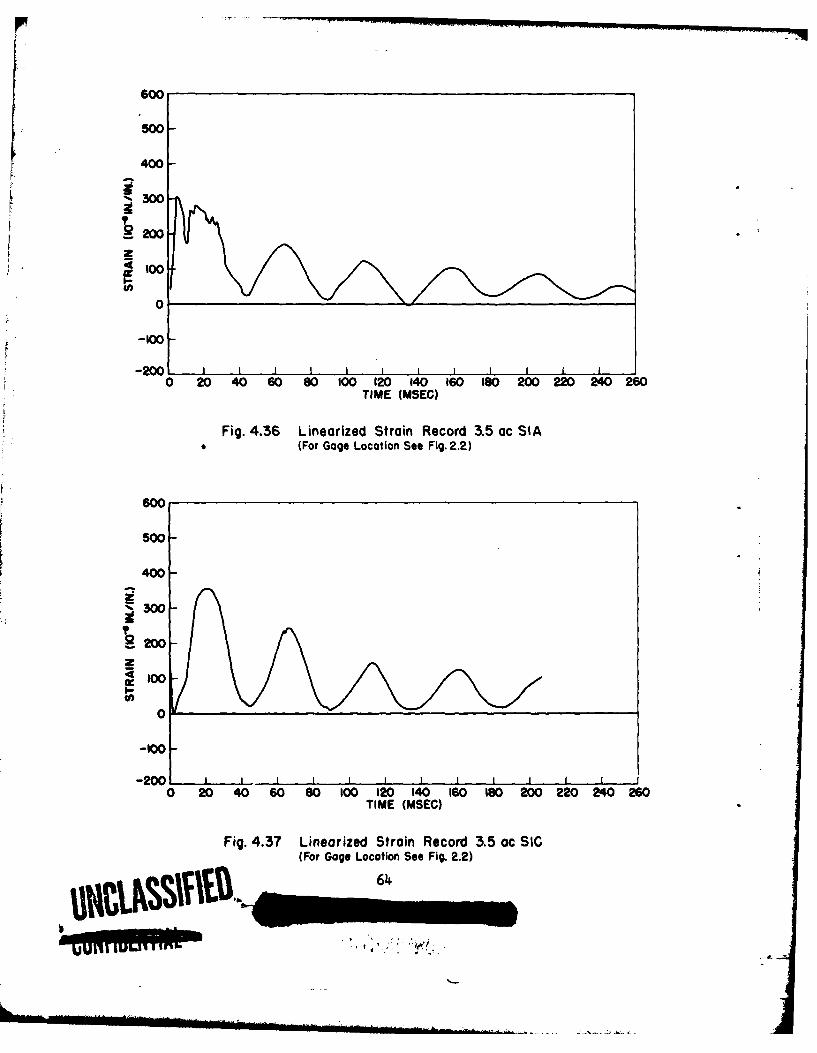
60
500
400
3200
zI00
0
-100
-200 1 1 1 1 I, I , I 1 I - -I I
0 20 40 60 80 100 120 140 160 180 200 220 240 26TIME (MSEC)
Fig. 4.36 Linearized Strain Record 3.5 ac SIA(For Gage Location See Fig. 2.2)
600
500
400
Z300
2200-
Z
0
-100-200 , , I I 1 I I I I
0 20 40 60 80 100 120 140 160 18 200 220 240 260TIME (MSEC)
Fig. 4.37 Linearized Strain Record 3.5 ac SIC(For Gage Location See Fig. 2.2)
SIT.VS- - 64
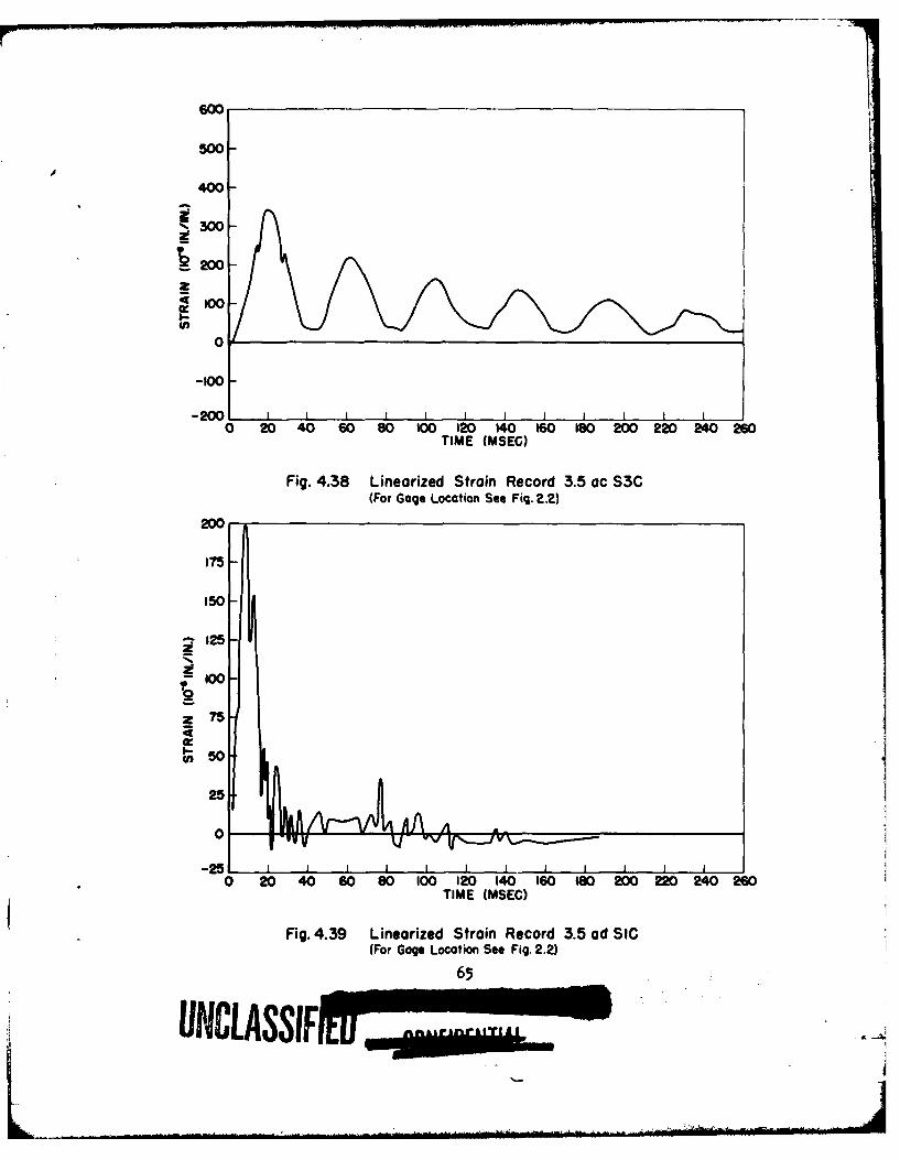
600
500-
400-
2. 00-
1200
I0
-0
-2001 L I I I I I I I I I I I0 20 40 60 80 100 120 140 160 180 200 220 240 260
TIME (MSEG)
Fig. 4.38 Linearized Strain Record 3.5 ac S3G(For Gage Location See Fig. 2.2)
200
150-
-125-
Z 75
50
0 2040 60 80100 120 140 160 0200 22024020TIME (MSEC)
Fig. 4.39 Linearized Strain Record 3.5 ad SIC(For Gage Location See Fig. 2.2)
65
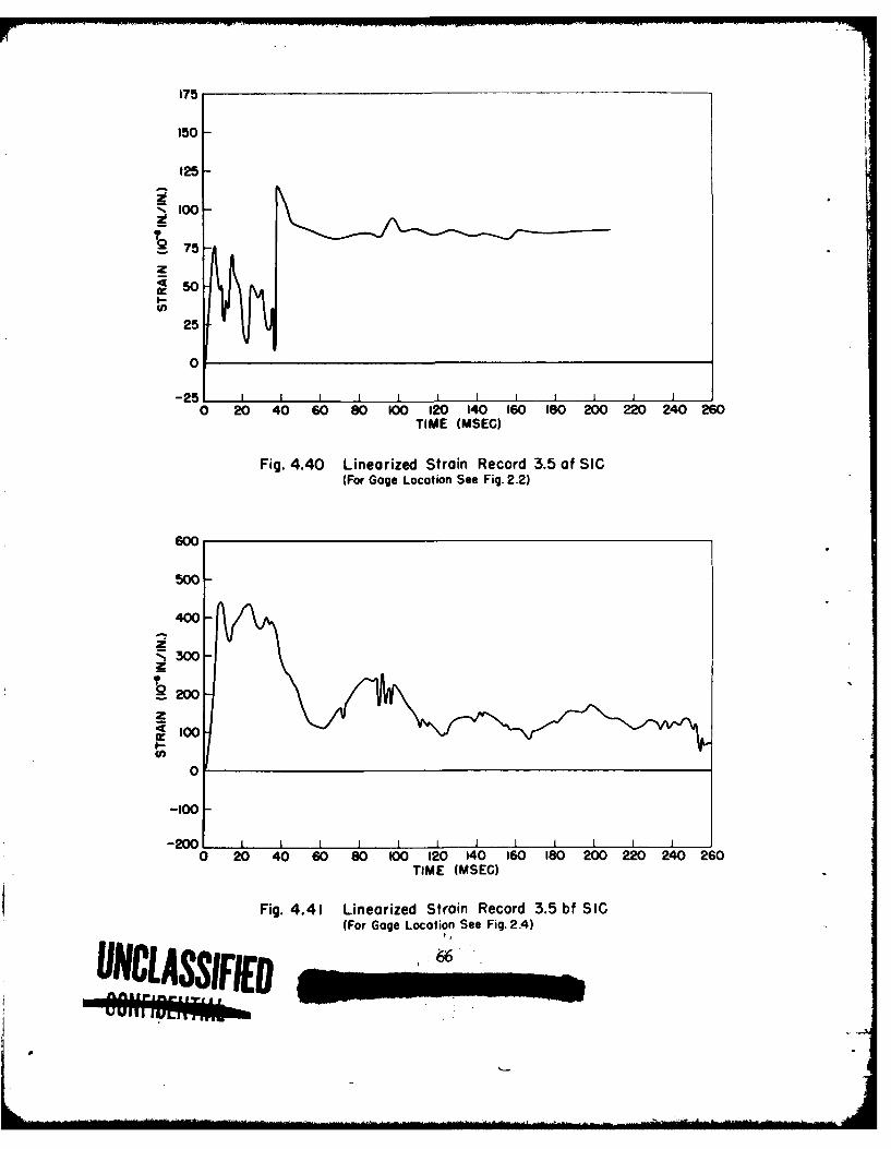
175
150
125
100
2
T-975 -
50
25
0
-25 I I I I0 20 40 60 80 100 120 140 160 180 200 220 240 260
TIME (MSEC)
Fig. 4.40 Linearized Strain Record 3.5 of SIC(For Gage Location See Fig. 2.2)
600
500-
400-
Z;Z 300-
20
I00
U)0
-1001
-200.0 20 40 60 80 100 120 140 160 180 200 220 240 260
TIME (MSEC)
Fig. 4.41 Linearized Strain Record 3.5 bf SIC(For Gage Location See Fig. 2.4)
UNCLASSIED
ar
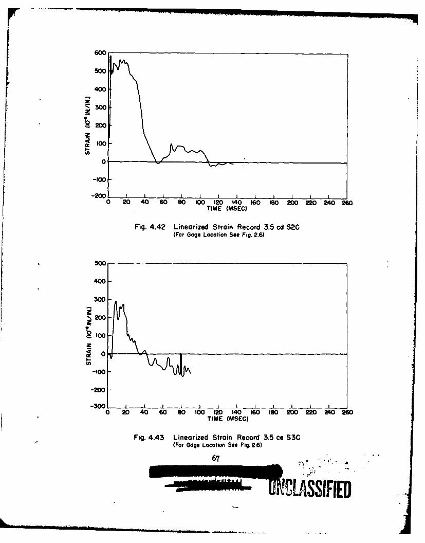
600
500
400
2WW
300-
~l0
-100
-2001 I I I I I I 1 I I 1 I0 20 40 60 80 100 120 140 160 180 200 220 240 260
TIME (MSEC)
Fig. 4.42 Linearized Strain Record 3.5 cd S2C(For Gage Location See Fig. 2.6)
500
400
300-
-100 -
-200
-300 I0 OD 40 W0 80 100 12D 140 160 180 200 220 240 2
TIME (MSEC)
Fig. 4.43 Linearized Strain Record 3.5 ce $3C(For Gage Location See Fig. 2.6)
67 " ""
2
+ +,+,-+ .. . ...... . . .0 ,.-,,.... 1 ,,i+....+
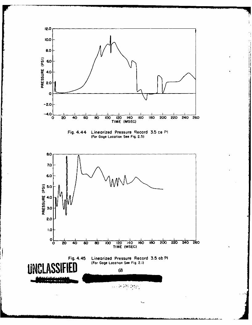
12.0
50.0-
8.0-
w .0
a.
(L
-2.0-
-2.01
0 20 40 60 80 100 120 140 160 180 200 220 240 260TIME (MSEC)
Fig. 4.44 Linearized Pressure Record 3.5 ce PI(For Gage Location See Fig. 2.5)
8.0
7.0-
6.0-
~5.0
0
0
0 20 40 60 80 100 120 140 160 180 200 220 240 260TIME CMSEC)
Fig. 4.45 Linearized Pressure Record 3.5 ab P1(For Gage Location See Fig. 2.1)
UNCLASSIFIE 6L8
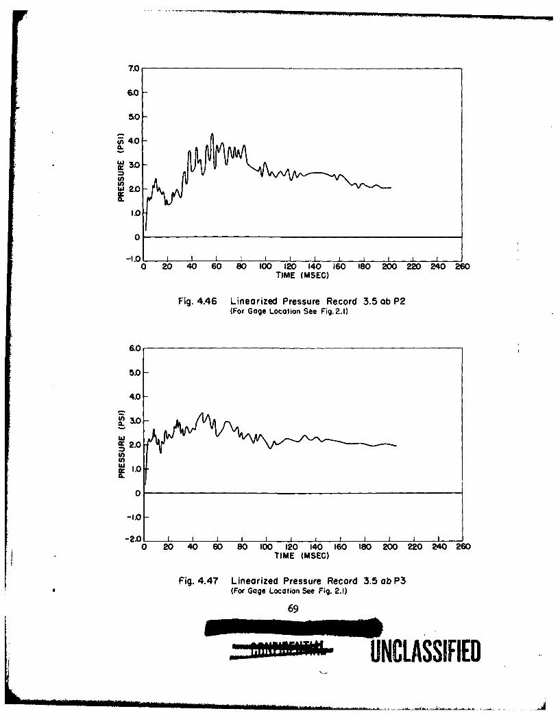
7.0
6.O
50
rii4.0
w 2,0
1.0
0
-
0 20 40 60 80 100 120 140 160 180 200 220 240 260TIME (MSEC)
Fig. 4.46 Linearized Pressure Record 3.5 ob P2(For Gage Location See Fig.2.1)
6.0
5.0
4.0
U) 3.0
wla.W= 2.0
S1.0-
0
-I.0-
-2.01 I 10 20 40 60 80 100 120 140 160 180 200 220 240 260
TIME (MSEC)
Fig. 4.47 Linearized Pressure Record 3.5 ob P3
(For Gage Location See Fig. 2.1)
69
UNCLASSIFIED
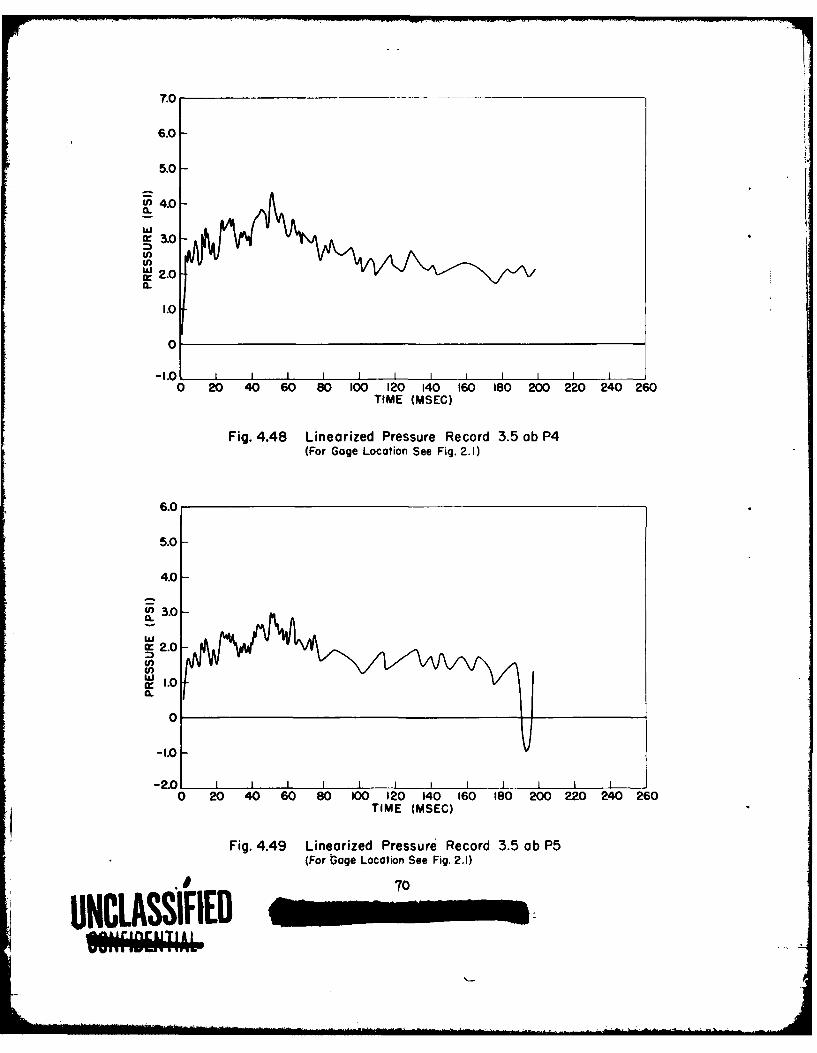
7.0 _ _ _ _ _ _ _
6.0-
5.0-
4.0
0
1w .0
0-
0 20 40 60 80 100 120 140 160 180 200 220 240 260TIME (MSEC)
Fig. 4.48 Linearized Pressure Record 3.5 ab P4(For Gage Location See Fig. 2.1)
6.0
5.0-
4.0-
-1 .0 -
Cr20 20 4 0 8 0 2 4 6 S 0 2 4 6
I.70
UNC~~LSFE_-1--
15.0
12.5-
CO 7.5-a.
~2.5-
0
-2.5-
-5.00 20 40 60 80 100 120 140 160 190 200 220 240 260
TIME (MSEC)
Fig. 4.50 Linearized Pressure Record 3.5 cb PI(For Gage Location See Fig. 2.5)
CHAPTER 5
DISCUSSION OF RESULTS
5.1 WALL ACTION
5.1.1 Blast Loading
5.1.1.1 Predicted Loads on Walls
The post-test predictions of blast loading on the wall panelsare discussed in Appendix B. Essentially, these predictions utilize thepretest prediction method, but use the observed free stream conditionsto describe the incident blast wave. The angle of incidence of the blastwave as seen in the horizontal plane differed from the planned head-onincidence because of the bombing error on Shot 9; this error varied from21 deg at cell 3.5c to 7 deg at cell 3.5a (see Fig. 2.10). The orienta-tion effect was not incorporated in the predictions given in Appendix B,but it can be shown that the error in applied forces probably does notexceed about 10 to 20 per cent at any instant of time for the 3.5c panels(predict d loads are high) and is considerably less for the other wallpanels.:_/ A comparison of the predicted applied loads with the trans-mitted loads as determined from strain gage measurements is given in
Figs. 5.1 through 5.10 and discussed in section 5.1.3. The predictedloads were computed as if the walls remained in place for all time.
5.1.1.2 Analysis of Pressure Record from Wall Panel 3.5ce
Only one pressure gage was utilized in connection with thewall panels. This gage was located in the interior of cell 3.5ce be-hind an 8 in. brick wall in the region of regular reflection at a groundrange of about 2160 ft, and at an incident blast overpressure of about12 psi.
i/ This estimate is based on shock tube and analytical studies of theeffects of orientation on blast loading of simple shapes struck byvertical shock fronts (Mach reflection region) conducted by the AR?in connection with other Air Force sponsored work.
72
UNCLASSIFIED
The gage was so placed as to give information on the buildupof pressure in the interior of buildings which have no windows and whosealls are expected to be destroyed by the blast. From such informationimproved estimates of blast effects on interior equipment and on columnsof such buildings can be made. While a wall may fail in the structuralsense in a very short time (frequently of the order of 10 or 20 me), thedebris may not clear from the opening until a relatively long period oftime has passed. Such slow movement can be expected to permit only arelatively long rise time pressure wave to enter the interior; the peakforces and the dynamic effects of the peak forces may be expected to beconsiderably lower than if the wall debris moved away earlier.
The gage was located as shown in Fig. 4.31. Its dimensionallocation was 2 ft 2 in. toward ground zero from the inside back wall,or about 5 ft behind the brick test wall. The gage was about half waybetween the floor and roof on the pilaster, and about 6 in. from thefront of the pilaster. The gage was positioned to read side-on pres-sure; this placed it side-on to the flying debris so that damage to thegage and erroneous signals due to impact with debris would be minimized.
A plot of the 3.5ce pressure record is shown in Fig. 4.44.Comments on the credibility of this record are indicated in Table 5.4.The table shows that the record is believed to be meaningful until 88 an,and, if corrected, until 140 ms. Since certain of the other gage plotsare believed to have incorrect pressure scales, it is felt that the pres-sure scale on the 3.5ce record should be used only with caution. However,an estimate is made later in this section that the scale may be satis-factory. The time scale and the shape of the plot, as far as the timenoted above, are believed to be very accurate.
From the behavior of the strain gage records, this wall ap-peared to fail structurally at 10 us after shock arrival, or earlier,and ceased to transmit force to its supporting structure after about60 me (see Fig. 5.3). No motion pictures were made at this location be-cause visibility was expected to be nearly zero. Therefore, the move-ment of the debris away from the opening cannot be estimated.
The pressure plot of Fig. 4.44 indicates that the peak pres-sure was reached at about 100 to 110 ms after shock arrival. The riseto this indicated peak is quite smooth and gradual (if correction ismade for effects believed to be erroneous at 88 and 104 me); the riseis very small until after about 50 us.
A few remarks can be made with regard to the pressure scale onthis plot. It is felt that the peak pressure will approximately equaloutside side-on pressure plus dynamic pressure since the rise time isso long and the rise so smooth. This conclusion is a consequence of therelatively small time (compared with rise time of the pressure) for rare-faction waves to move across the interior. This rarefaction travel timeis of the order of 5 me for one transit of the interior; three to fivetransits probably suffice to lower pressures in the cavity to the cur-rent pressure outside and immediately in front of the cavity (side-onplus dynamic pressure). The value of side-on pressure plus dynaaic pres-sure at the time of the peak on this gage plot is about 10 psi. Thisvalue would lie about 1 psi below the pea-k on the gage plot if a
73
NCLASSIFIE
reasonable correction were applied for the baseline shift and oscil-lation noted in Table 5.4.
The record, therefore, shows that after structural failuremy be said to have occurred, the brick wall moved very little (as faras admission of pressure is concerned) for about 50 ms and did not move
enough to admit full outside pressure until 100 ms or more. This indi-
cates that for structures with no windows or doors (and with no earlyroof failures), but with walls which fail rapidly, the buildup of pres-
sure in the interior is so gradual that interior items whose responseis influenced principally by peak pressures will tend to sustain con-siderably less damge than if exposed to the outside shock wave.
The effect of wall debris in slowing the rate of interiorpressure buildup has been indicated by this test to be a considerablymore important factor for blast loadings on interior equipment, down-stream wall, and columns and trusswork than might have been expectedheretofore. Testing of this effect is being planned for shock tubeexperimentation. Depending on the outcome of such laboratory tests, itmay be desirable to perform additional field tests of this nature withdifferent wall material and with larger structures.
5.1.2 Determination of Transmitted Forces
The forces transmitted by a , anel to the supporting struc-ture are measured directly as strain3 sensor bars (C-gages,
Figs. 2.2, 2.4, and 2.6). The axial f .-asured in the plane ofthe panels (A-gages) are discussed in 7Upter 6 in connection with thefailure theories.
Of interest is the manner in which the forces in the sensorbars are converted into total transmitted force for the panel. Sincemeasurements were obtained at discrete points, it is necessary to knowthe distribution of the reactions along the edge of the panel in orderto determine the total transmitted force. This distribution will dif-fer for the various panels tested. The reinforced concrete and masonrypanels behaved as two-way slabs; the lightweight covering exhibited one-way or beam action.
Due to the manner of construction, the wood siding panel (3.5af)probably transmitted load to the top and bottom sensors as concentratedforces at the studs. Since the sensor assembly is essentially a beamon continuous supports, the forces in all of the sensor bars should beapproximately equal. Thus, the total load transmitted by the top andbottom edges of the panel is taken to be the measured force in the sen-sors directly under the center stud multiplied by the number of sensorbars along the edge.
One-way slab action of the panel cannot take place until thestuds have failed. The reactions along the sides parallel to the studsare assumed to be distributed uniformly during the entire loading per-iod. In this case, the total force transmitted to the sides is equalto the load per unit length multiplied by the length of the side. Theload per unit length is approximately equal to the force measured inthe center sensor bar divided by the length of the side contributing
734
W" Ut
to this bar, i.e., the distance between adjacent bars. The total forcetransmitted by the panel is then the sum of the transmitted forces alongeach of the four edges.
The approximate manner of estimating the distribution of re-actions probably yields a high value of the total transmitted force.Even so, only a small portion of the applied load was transmitted tothe supporting structure since the panel failed completely. Therefore,errors in the present approach are not significant.
The corrugated asbestos board and corrugated sheet steel panelsare constructed in the same manner and are considered together. Fig-ure 4.9 is an enlargement of the motion picture film at the instant ofbreak for the corrugated asbestos board panel, 3.5ae. As can be seen,each subpanel acts independently as a beam. Thus, the force transmittedalong the top and bottom edges is assumed to be distributed uniformlyand is computed as above. The center girt transfers load to the sidesensors as a concentrated force. Under this condition of loading thecenter sensor is assumed to measure all of the transmitted load. Thisis not strictly correct since portions of the load are transferred toadjacent sensor bars. However, the error introduced is believed to besmall, and again these panels transmitted only a small fraction of theirload to the supports.
The remaining panels tested all acted as two-way slabs. Thisis clearly evident from the fact that the reactions on adjacent sidesare of the same order of magnitude, and that the failure pattern ischaracteristic of plate behavior (e.g., cracks emanating from the cor-ners at about 45 deg). After establishing plate action, it is neces-sary to determine the end fixities in order to find the shear distri-bution along the edges. Both the ratio of forces measured on adjacentsides and the comparison of measured versus computed periods of vibra-tion point to the existence of simply-supported edge conditions.
For an elastic plate supported in this manner, under the actionof a static uniformly applied load, it is known that the distributionof shear along the edges is in the form of a half sine wave. It sohappens that for a plate with clamped edges and of the proportionstested, the distribution of shear is closely approximated by the sinedistribution. Thus, in any case, the sine distribution is felt to be anadequate approximation.
The total force transmitted to the structure along any edge, Ris taken to be,
2R = -- q L
where q is the maximum shear per unit length along the edge and L isthe length of the edge. This relation is simply the area under one loopof a sine wave of amplitude q and wave length 2L. The quantity qis computed from the measured force as described previously. The total
force transmitted by the panel is the sum of the R's for the four sides.It might be noted that elementary plate theory demands that, for
simply-supported edges, concentrated forces act at the corners of theplate in the direction of the applied load. These compensate the shear
75
resulting from twisting moments acting along the edges and prevent the
corners from rising; for clamped plates the corner forces vanish. In
the present case, where no provision for corner restraint was provided,and where cracking might have occurred, it is probable that these forcesdid not develop, or at least they cannot be computed according to con-ventional theory. In any case it is believed that the shear distribu-tion along the edges of these panels did not differ appreciably fromthe assumed sine distribution. This view is apparently borne out bythe agreement between the average transmitted and predicted appliedload for the two brick panels which remained intact (Figs. 5.1 and 5.2).
In connection with the distribution of reactions for masonrypanels, it might be noted that the zest results do not support the viewthat there is a "strog'.' and "weak" direction for these panels, at leastunder the action of dynamic loads. Rather, the measured reactions arein agreement with what one would expect for a 'iimply-supported homo-geneous elastic plate of the dimensions tested.
5.1.3 Comparison with Predicted Blast Forceb
5.1.3.1 Introduction
The force transmitted by each test panel to its supportingstructure is compared with the predicted blast force on the paneJl inthe present section. As discussed later, this comparison indicatesthat when a wall remains intact, the predicted applied force serves asa good estimate of the average transmitted load, whereas when a wallfails the impulse of the transmitted force can be correlated in a sim-ple fashion with the diffraction impulse of the predicted applied force(the reinforced concrete panel is an exception). These tentative con-clusions form the basis of the proposed simplified method for the pre-diction of transmitted forces discussed in Chapter 6.
It should be noted that a direct comparison between predictedand applied load on the exterior of the panel and the measured forcetransmitted by the panel to its supporting frame affords only an indi-rect check on the validity of the former values. This is due to thefact that the load prediction method (given in Appendix B) does not ac-count for motion of the panel during passage of the blast wave, whereasthe force actually transmitted depends on the physical properties ofthe panel as well as on the incident blast.
5.1.3.2 Masonry Walls
The comparison between predicted and transmitted forces (re-duced to unit forces) is shown in Figs. 5.1 through 5.6 for the masonrywall panels tested. The two brick walls which remained in place (Figs.5.1 and 5.2) acted essentially as damped single-degree-of-freedom systems./ The distinction between these forces, frequently referred to through-
out this report as "predicted applied" and "transmitted" forces,should be kept clearly in mind.
76
The wall at the higher loading (3.5bf, Fig. 5.2) shows a nonlinear be-havior in that the period of the vibration is seen to vary from about65 ms initially to about 45 ms toward the end of the trace; the otherpanel has a constant period of about 45 ms. This action is quite in-teresting and is discussed in connection with the Arching Action theoryof masonry walls in Chapter 6.
In any event, the relatively high frequency response of thebrick walls, which is probably representative of the action of mostmasonry panels met with in practice, indicates the predicted blastload to be a good estimate of the average load transmitted to the struc-ture, provided of course the panel remains intact during the entireloading period.
With reference to Figs. 5.1 and 5.2, it is seen that for bothwalls the transmitted load drops below the predicted value toward theend of the blast pulse, whereas it should of course oscillate about theapplied load. As discussed in Appendix B, the predicted load is basedon the following analytical approximation for the time variation of thefree-stream pressure wave,
-ctp,(t)-eto( t0
where c = 1, and the rest of the quantities are as defined in Appendix B.Now indications are that values of c greater than unity
should have been used in the post-test load prediction computations.The exact shape of the incident pressure wave at the test locations isnot known. However, based on the results of Project l.lb (Air Pres-sure Versus Time, WT-711) it appears that for 3.5ac (6700 ft groundrange) c = 1.6, and for 3.5bf (4500 ft ground range) c = 2.2. Thesevalues are only approximate since they were determined by curve fittingthe pressure-time records obtained at ground ranges of 6536 ft (SRI gage85B) and 4558 ft (SRI gage 9b), and are based on only the first 300 usof these traces.
The variation of c with yield, height of burst, and groundrange has been considered in connection with other work being conductedat the ARF (Project 3.1, Tests on BuildinRg and Equipment Shaves), andthese results lead to values of c - 1.3 for 3.5ac and c = 2.2 for 3.5bf,which are in rather good agreement with the above values. However, itwas found empirically that using c n 3.0 for 3.5ac and c a 1.6 for 3.bfbrings the predicted and transmitted forces shown in Figs. 5.1 and 5.2into the most satisfactory agreement.
Since these values indicate a trend in opposition to the valuesbased on experimental data, it may be that the discrepancy between thepredicted and transmitted forces noted above is not due to errors in theload prediction scheme alone. More likely the explanation is to be foundin a combination of errors resulting from (a) the location of the baselineof the strain records, (b) the method of averaging the individual strainrecords, and (c) improper representation of the incident blast wave.
77
__ __UNLASSIFEI
77
Some estimate as to the validity of the load prediction method(applicable to front walls in the Mach reflecticn region) can be madefrom the response of the brick wall which acted as a linear system(3.5ac, Fig. 5.1). The general equation of motion for forced vibrationof a linear one-degree-of-freedom "mass-spring" system with damping canbe written in the following nondimensional form:
X+29W i + x w f(t) (5.1)
where the terms are defined as follows:
x = = nondimensional displacement in multiples of theF static displacement of the system due to the peak
applied force
x = actual displacement of "spring"
k = stiffness of spring (kx a force in spring)
F = peak applied force (F/k = static displacement ofspring due to force F)
R = per cent of critical damping
W a = natural frequency of system
m - mass of system
f(t) = nondimenslonal time-dependent applied force (maximumvalue of f(t) = 1)
t = time
= nondimensional velocity of system
= nondimensional acceleration of system.
The natural period of vibration, ,J was found to be 45 ms percycle (the maximum variation in this value was about + 10 per cent fromcycle to cycle and record to record). The damping ra7io was determinedfrom the logarithmic decrement (i.e., the logarithm of the ratio of twosuccessive amplitudes of the vibration) and was found to vary between4 and 8 per cent, depending on the record considered. These values arein excellent agreement with the damping values for brick quoted in theliterature.
The first maximum value of X corresponds to the ratio ofpeak transmitted force (kx) to peak applied force (F), and in the pres-ent case depends only on the rate of decay of the linear portion ofthe applied load, f(t), in addition to W and 0 . For the wall underconsideration this ratio is computed to be about 1.35 whereas the meas-ured value is about 1.5. If undamped motion (B = 0) is assumed up tothe first peak, this ratio is computed to be 1.5, which is in excellentagreement with the measured value. It may be, therefore, that the damp-ing forces were first introduced after the first peak had occurred; thisaction might be explained by the fact that some cracking occurred in the
783- -IARED IMF-
all about the time the maximum displacement was reached. However, nodefinite conclusions can be drawn since the differences in these quan-
- titles are now probably of the order of errors in the analysis itself.Equation 5.1 was solved for the predicted loading (the decay
rate during the drag phase was corrected as discussed previously) andis compared in Fig. 5.11 with the measured transmitted force. Theagreement with the measured values is seen to be quite good, and thesesimple response computations tend to confirm the general character ofthe predicted loading within the Mach region as well as the over-allaccuracy of the strain measuring system.
The other panels of masonry construction (i.e., 3.5bd, be,cc, and ce) were all destroyed during the test. The strain records forthese panels indicate that initial failure occurred in about the first20 ms after shock arrival (that is, within about the first half periodof vibration for these panels), and that the transmitted load vanishedbetween about 50 and 100 ms. These break times compare rather favorablywith the values given in Table 4.1, which were obtained from the motionpicture films.
Table 5.1 shows a comparison of wall behavior based on thetotal impulse of the transmitted force (per unit area) expressed as apercentage of the diffraction impulse of the applied forceJ/ It isseen that the masonry walls transmitted between about 50 and 150 percent of the applied diffraction impulse prior to complete failure. Also,inspection of Figs. 5.3 through 5.6 indicates that much of this impulsewas transmitted in a time of the order of the duration of the diffractionloading.
The extent to which the results of Table 5.1 are applicableto masonry wall behavior in general is not known. The impulse trans-mitted prior to failure probably must be assumed to depend on the loadcausing failure. Thus, the results of Table 5.1 should not be taken toimply that the magnitude of the transmitted impulse will necessarilyincrease with increasing overpressure -- a result which is certainlynot supported by the test, since only one wall of each type was destroyed.However, if it is assumed that a masonry panel will always fail in aboutthe first half period of its vibration, as indicated by the test (andthis seems reasonable enough), then the results of Table 5.1 are proba-bly indicative of masonry wall behavior over a reasonable range of loadscausing failure and, in fact, my well serve to bracket the impulse amasonry panel is capable of transmitting prior to failure.
This tentative conclusion is based on the observation that thecomposite wall, 3.5cc, which failed at 12 psi and transmitted the great-est percentage impulse (about 150 per cent), probably would have remained
The term diffraction Impulse as used here refers to the impulse(area under the net force-time diagram) of the applied force up tothe time pseudo-steady state pressures are reached (see Appendix B).It should be noted that the uncertainty in the shape of the inci-dent pressure wave discussed previously has only a negligible ef-fect on the diffraction impulse.
79
- UNCLASSIFID
TABLE 5.1 - Comparison of Predicted Applied and Transmitted Impulses
for Wall Panel Which Failed
overpressure Predicted Applied Measured(psi) I I Transmitted I Tt
Panel Tp Dp Is-e(lOO)(psi-sec) (psi-sec, (psi-ic) Dp
3.5bd, 8 in. Cin- 7.1 2.73 0.34 0.18 53der Block
3.5ce, 8 in. Brick 12 3.66 0.49 0.34 70
3.Sbe, 12 in. Cin- 7.1 2.73 0.34 0.34 100der Block
3.5cc, 4 in. Brick, 12 3.68 0.49 0.72 1478 in. Cinder Block
3.5cd, 6 in. Rein- 12 3.68 0.49 1.58 323forced Concrete
3.Sad Corrugated 4.2 1.69 0.19 0.04 21Steel
3.5ae, Corrugated 4.2 1.69 0.19 0.04 21Asbestos
3.5af, Wood Siding 4.2 1.69 0.19 0.16 84
ITp = Impulse of total predicted blast loading
IDp = Impulse of diffraction portion of predicted blast loading
ITt = Impulse of total transmitted force
UNCLASSIFIED,U1
intact as 11 psi as discussed in Chapter 6. Thus, a masonry wall whichfails may not be capable of transmitting an impulse substantially inexcess of 150 per cent of the applied diffraction impulse associatedwith the critical overpressure.9/ At the other extreme, the 8 in.cinder block wall, 3.5bd, which probably would have failed at about2.5 psi, was actually subjected to 4 psi and still transmitted about50 per cent of the applied diffraction impulse -- or about 150 per centof the diffraction impulse associated with the estimated critical over-pressure (i.e., 2.5 psi). Thus, it might be inferred that a masonrypanel will generally transmit an impulse of the order of 150 per centof the diffraction impulse associated with the critical overpressure
prior to failure.Naturally the results of a single test cannot be carried too
far. But in view of the present status of knowledge, even extreme gen-eralization of these results is considered justified at this time. Anadditional point should be noted. The test results are also dependenton the fact that the panels were restrained (i.e., supported betweencolumns) on all four edges. The strain gages which measured reactionsin the plane of the panel indicate these forces to be of a magnitudecomparable to the normal reactions which have been zonsidered so far.As discussed in subsection 6.2.1.1, the walls would probably have failedin simple bending, and at a much lesser pressure had they not been re-strained on at least two opposite edges. In fact, the 8 in. brick wall,which was not destroyed in a 7 psi region, would probably have failedin bending at about 2 psi had it not been restrained along the sides.Thus, the present results must be restricted to panels restrained onat least two opposite edges, i.e., supported between or continuous overcolumns. The expected difference in response between a panel restrainedon all four sides and one restrained on only two opposite sides is consid-ered in section 6.2.1.2.
5.1.3.3 Reinforced Concrete Wall
The comparison between transmitted and predicted blast forcefor the reinforced concrete wall is shown in Fig. 5.7 and Table 5.1.This panl transmitted about 43 per cent of the predicted total appliedimpulseS/ (better than three times the predicted diffraction impulse).It continued to transmit force for about 150 ms after failure was ini-tiated and actually remained in place for about 250 ms. Figure 4.17shows that the panel was removed almost bodily from the test cell, andwhatever bond existed between the reinfcrcing steel and the sensor-supporting system was probably instrumental in keeping the panel inplace for this length of time. It can be imagined that if the steelhad been attached more securely to the structure (e.g., monolithic con-struction) the panel, while suffering extreme cracking, might have!V The term critical overpressure refers to the blast loading at which
wall failure will just occur; determination of these pressures isconsidered in Chapter 6.
5/ There is some uncertainty in this value due to the error in the pre-dicted value of te total impulse discussed in connection with themasonry walls.
81
'4" IFIIF
remained in place and transmitted a good deal more of the applied load.
In other words, due to the relatJvely wide variation in design and con-struction practice found for reinforced concrete walls, the results ofthis test may not have wide applicability.
5.1.3.4 Lightweight covering
The comparison between transmitted and predicted blast forcefor the corrugated sheet steel panel (3.5ad), the corrugated asbestos
board panel (3.Sae), and the wood siding panel (all being referredto as lightweight covering) is shown in Figs. 5.8, 5.9, and 5.10 andin Table 5.1. The first two mentioned panels were both fully removedfrom their test cells in the first 20 ms or so of the loading, andtransmitted only about 20 per cent of the applied diffraction impulseduring this time.
While the over-all action of these two walls were nearly iden-tical and the transmitted impulses are probably representative of mostwalls of this type, several possible exceptions should be noted. Forexample, in certain instances the end connections of the center girtmight fail at loads which the panel as a whole could withstand.
Thus, the wall would be blown out of the structure essentially intactand the transmitted impulse would not depend entirely on the strengthof the covering.
Another exceptional case is that in which the girt and itsconnections are substantially stronger than under the test conditions.The girt might then remin in place even though the siding failed. Inthis event the steel siding wall might transmit a much greater impulsethan a similar asbestos board wall since an appreciable amount of thesteel covering would probably remain attached to the girt. (Fig. 4.8this to be the case when the girt fails.) In each of the above casesthe transmitted impulse would be expected to differ from the test re-sults.
The wood siding panel remained in place for about 50 or 60 msand transmitted 84 per cent of the applied diffraction impulse duringthis time. From static considerations the studding of this wall is ex-pected to fail at a somewhat lesser load than the siding between studs.Thus, gross failure of this panel probably occurred after some of thecenter studs failed. The mode of failure apparent from the motion pic-ture films, section 4.1.6, tends to confirm this action.
5.2 ROOF ACTION
5.2.1 Predicted Loads on Roofs
The post-test predictions of blast loadings on the roof panelsare discussed in Appendix B. These predictions use the pretest methodwith observed pressure values for the incident blast wave. The angleof incidence of the blast wave as seen in the horizontal plane differedfrom the planned head-on incidence because of the bomb dropping erroron Shot 9. This error in angle varied from 21 deg at 3.5c to 7 deg at
82
' U .
• .. p
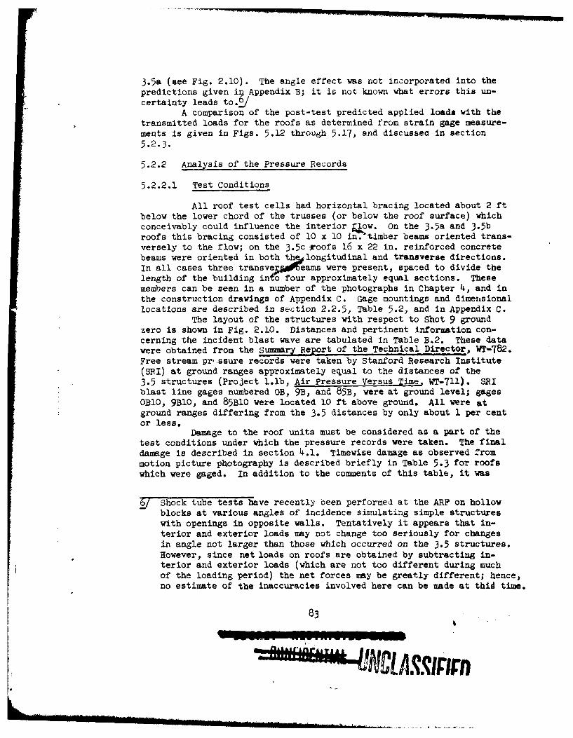
3.5a (see Fig. 2.10). The angle effect was not incorporated into thepredictions given in Appendix B; it is not known what errors this un-certainty leads to&
A comparison of the post-test predicted applied loads with thetransmitted loads for the roofs as determined from strain gage measure-ments is given in Figs. 5.12 through 5.17, and discussea in section5.2.3.
5.2.2 Analysis of the Pressure Records
5.2.2.1 Test Conditions
All roof test cells had horizontal bracing located about 2 ftbelow the lower chord of the trusses (or below the roof surface) whichconceivably could influence the interior Qow. On the 3.5a and 3.5broofs this bracing consisted of 10 x 10 in.timber beams oriented trans-versely to the flow; on the 3.5c roofs 16 x 22 in. reinforced concretebeams were oriented in both thqglongitudinal and transverse directions.In all cases three transve eams were present, spaced to divide thelength of the building into four approximately equal sections. Thesemembers can be seen in a number of the photographs in Chapter 4, and inthe construction drawings of Appendix C. Gage mountings and dimensionallocations are described in section 2.2.5, Table 5.2, and in Appendix C.
The layout of the structures with respect to Shot 9 groundzero is shown in Fig. 2.10. Distances and pertinent information con-cerning the incident blast wave are tabulated in Table B.2. These datawere obtained from the Summary Report of the Technical Director, WT-782.Free stream pr'.ssure records were taken by Stanford Research Institute(SRI) at ground ranges approximately equal to the distances of the3.5 structures (Project 1.1b, Air Pressure Versus Time. WT-711). SRIblast line gages numbered OB, 9B, and 85B, were at ground level; gagesOB10, 9B10, and 85B10 were located 10 ft above ground. All were atground ranges differing from the 3.5 distances by only about 1 per centor less.
Damage to the roof units must be considered as a part of thetest conditions under which the pressure records were taken. The finaldamage is described in section 4.1. Timewise damage as observed frommotion picture photography is described briefly in Table 5.3 for roofswhich were gaged. In addition to the comments of this table, it was
6/ Shock tube tests have recently been performed at the ARF on hollowblocks at various angles of incidence simulating simple structureswith openings in opposite walls. Tentatively it appears that in-terior and exterior loads may not change too seriously for changesin angle not larger than those which occurred on the 3.5 structures.However, since net loads on roofs are obtained by subtracting in-terior and exterior loads (which are not too different during muchof the loading period) the net forces may be greatly different; hence,no estimate of the inaccuracies involved here can be made at thid time.
83
, . .. Till
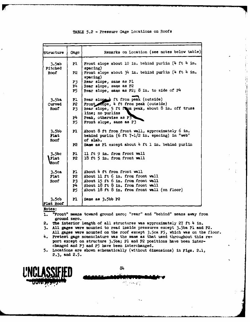
TABLE 5.2 - Pressure Gage Locations on Roofs
Structure Gage Remarks on Location (see notes below table)
3.Sab P1 Front slope about 10 in. behind purlin (4 ft 4 in.Pitched spacing)Roof P2 Front slope about 34 in. behind purlin (4 ft 4 in.
spacing)P3 Rear slope, same as P1P4 Rear slope, same as P2P5 Rear slope, same as P2; 8 in. to side of P4
3.5ba P1 Rear slos ft from Pea (outside)Curved P2 Front pe 4 ft from peak (outside)Roof P3 Rear slope, 5 ft m peak, about 8 in. off truss
line; no purlinsP4 Peak, otherwise as PP5 Front slope, same as P3
3.5bb P1 About 8 ft from front wall, approximately 6 in.Flat behind purlin (6 ft 7-1/2 in. spacing) in "web"Roof of slab.
P2 Same as P1 except about 4 ft 1 in. behind purlin
3.5bc P1 11 ft 9 in. from front wall'Flat P2 18 ft 5 in. from front wallRoof
3.5ca P1 About 4 ft from front wallFlat P2 About 11 ft 6 in. from front wallRoof P3 About 15 ft 6 in. from front wall
P About 18 ft 8 in. from front wallP5 About 18 ft 8 in. from front wall (on floor)
3.5cb P1 Same as 3.Sbb P2Flat Roof 1Notes:1. "Front" means toward ground zero; "rear" and "behind" means away from
ground zero.2. The interior length of all structures was approximately 27 ft 4 in.3. All gages were mounted to read inside pressures except 3.5ba P1 and P2.
All gages were mounted on the roof except 3.5ca P5, which was on the floor.4. Pretest gage nomenclature was the same as that used throughout this re-
port except on structure 3.5ba; P1 and P2 positions have been inter-changed and P3 and P5 have been interchanged.
5. Locations are shown schematically (without dimensions) in Figs. 2.1,2.3, and 2.5.
84
UD ~ 1. : .~.. -"I
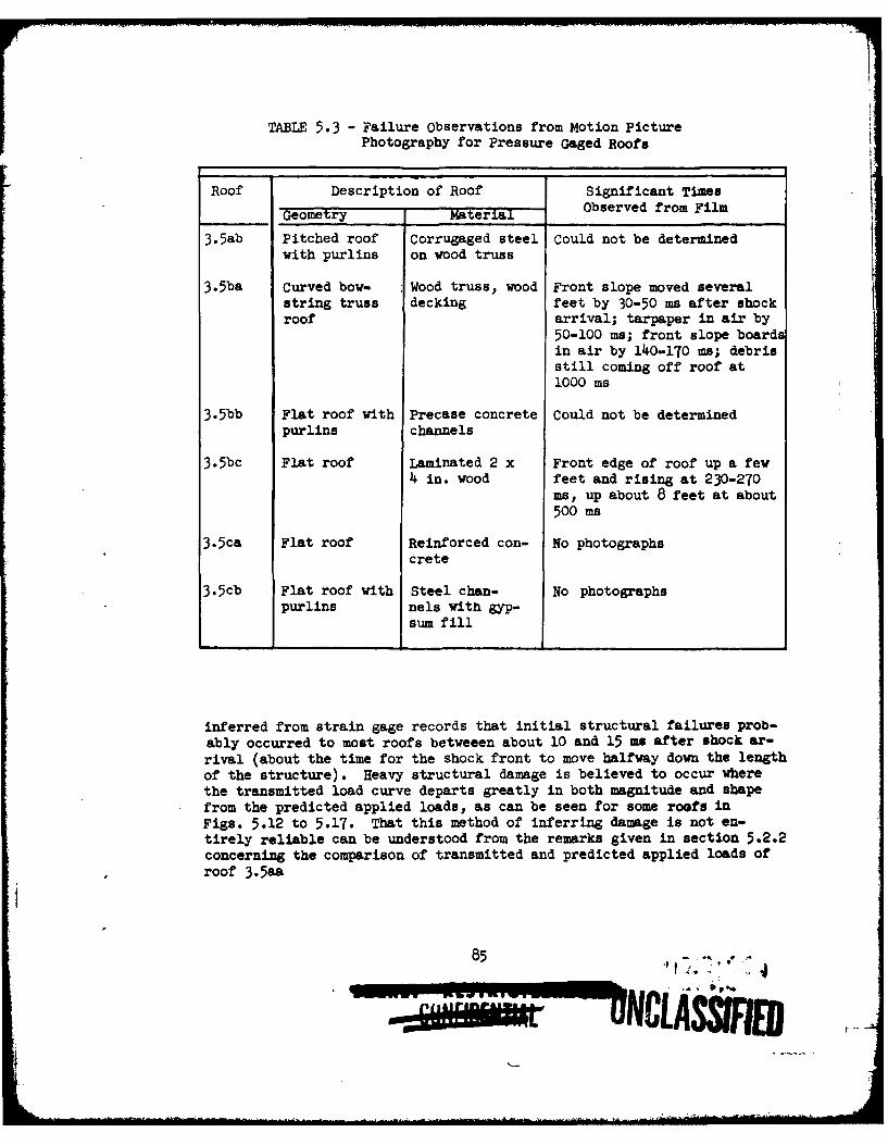
TABLE 5.3 - Failure Observations from Motion PicturePhotography for Pressure Gaged Roofs
Roof Description of Roof Significant Times
Geometry Mater a Observed from Film
3.5ab Pitched roof Corrugaged steel Could not be determined
with purlins on wood truss
3.Sba Curved bow- Wood truss, wood Front slope moved severalstring truss decking feet by 30-50 ms after shockroof arrival; tarpaper in air by
50-100 me; front slope boardsin air by 140-170 ms; debrisstill coming off roof at1000 ms
3.5bb Flat roof with Precase concrete Could not be determinedpurlins channels
3.5bc Flat roof Laminated 2 x Front edge of roof up a few4 in. wood feet and rising at 230-270
ms, up about 8 feet at about500 ms
3.5ca Flat roof Reinforced con- No photographscrete
3.5cb Flat roof with Steel chan- No photographspurlins nels with gyp-
sum fill
inferred from strain gage records that initial structural failures prob-ably occurred to most roofs betweeen about 10 and 15 ms after shock ar-rival (about the time for the shock front to move halfway down the lengthof the structure). Heavy structural damage is believed to occur wherethe transmitted load curve departs greatly in both magnitude and shapefrom the predicted applied loads, as can be seen for some roofs inFigs. 5.12 to 5.17. That this method of inferring damage is not en-tirely reliable can be understood from the remarks given in section 5.2.2concerning the comparison of transmitted and predicted applied loads ofroof 3.5aa
85 - , -
I I I WI
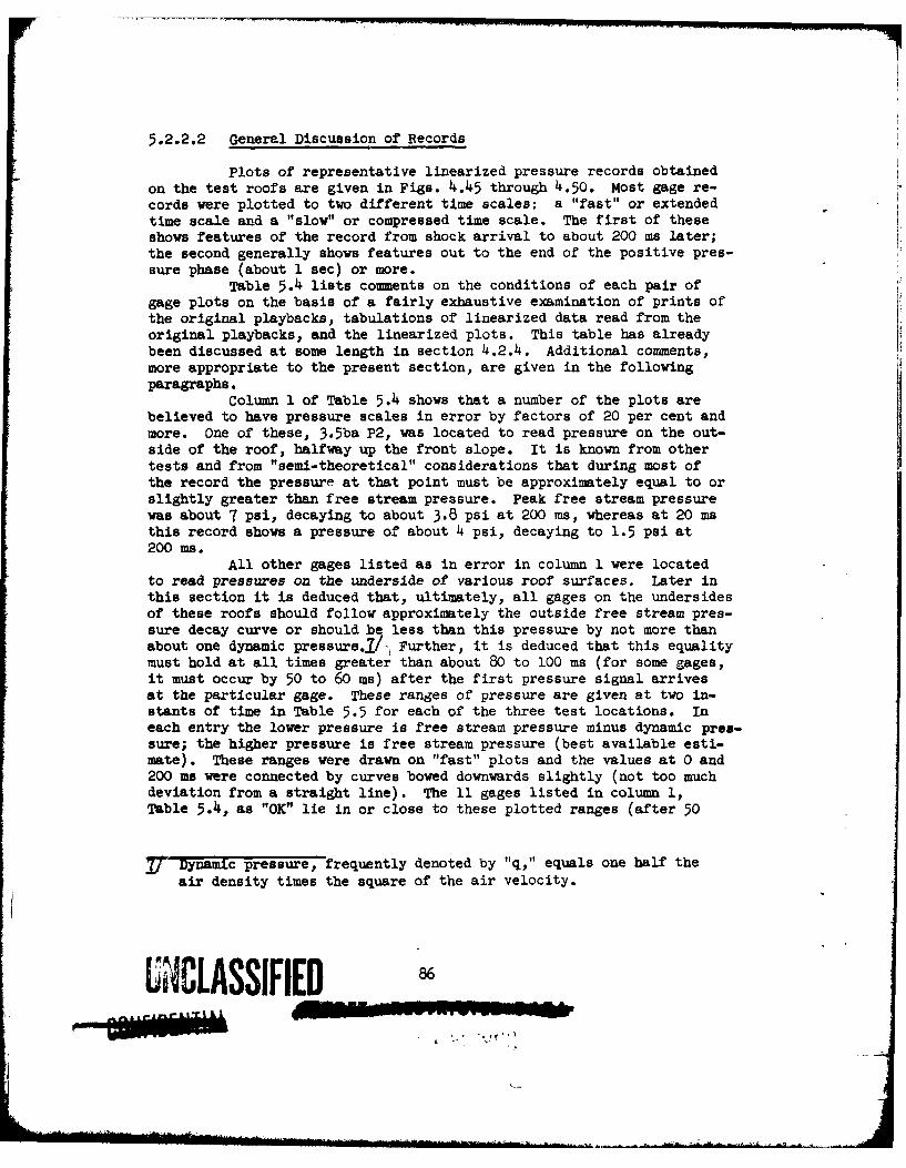
5.2.2.2 General Discussion of Records
plots of representative linearized pressure records obtainedon the test roofs are given in Figs. 4.45 through 4.50. Most gage re-cords were plotted to two different time scales: a "fast" or extendedtime scale and a "slow" or compressed time scale. The first of theseshows features of the record from shock arrival to about 200 ms later;the second generally shows features out to the end of the positive pres-sure phase (about 1 sec) or more.
Table 5.4 lists comments on the conditions of each pair ofgage plots on the basis of a fairly exhaustive examination of prints ofthe original playbacks, tabulations of linearized data read from theoriginal playbacks, and the linearized plots. This table has alreadybeen discussed at some length in section 4.2.4. Additional comments,more appropriate to the present section, are given in the followingparagraphs.
Column 1 of Table 5.4 shows that a number of the plots arebelieved to have pressure scales in error by factors of 20 per cent andmore. One of these, 3.5ba P2, was located to read pressure on the out-side of the roof, halfway up the front slope. It is known from othertests and from "semi-theoretical" considerations that during most ofthe record the pressure at that point must be approximately equal to orslightly greater than free stream pressure. Peak free stream pressurewas about 7 psi, decaying to about 3.8 psi at 200 ms, whereas at 20 msthis record shows a pressure of about 4 psi, decaying to 1.5 psi at200 ms.
All other gages listed as in error in column I were locatedto read pressures on the underside of various roof surfaces. Later inthis section it is deduced that, ultimately, all gages on the undersidesof these roofs should follow approximately the outside free stream pres-sure decay curve or should be less than this pressure by not more thanabout one dynamic pressure..I/- Further, it is deduced that this equalitymust hold at all times greater than about 80 to 100 ms (for some gages,it must occur by 50 to 60 ms) after the first pressure signal arrivesat the particular gage. These ranges of pressure are given at two in-stants of time in Table 5.5 for each of the three test locations. Ineach entry the lower pressure is free stream pressure minus dynamic pres-sure; the higher pressure is free stream pressure (best available esti-mate). These ranges were drawn on "fast" plots and the values at 0 and200 ms were connected by curves bowed downwards slightly (not too muchdeviation from a straight line). The 11 gages listed in column i,Table 5.4, as "OK" lie in or close to these plotted ranges (after 50
/ Dynamic pressure, frequently denoted by "q," equals one half theair density times the square of the air velocity.
UNCLASSIFIEDA' a
to 100 ms, depending on the gage). The plots of inside gages8/ whichare stated in column 1 to be in error required the corrections notedin column 1 to bring them midway within these ranges.
The deduction that inside pressures must ultimately lie inthe ranges given in Table 5.5 is made as follows: For blast waves whichare as long compared with building length as was the case here, it hasbeen observed in the past that ultimately the pressure at every point ofa structure approximately reaches and follows some curve which is relatedsimply to the decaying free stream pressure curve. This related curvecan be approximated fairly closely by adding or subtracting from freestream pressure the dynamic pressure curve multiplied by some constant(usually between 0 and 2).
Intuitive arguments support this observation, which has beenmade in other field tests, other UPSHOT-KNOTHOLE results, and in shocktube tests. This, of course, simply means that some "pseudo steadystate" has been reached at all points of the structure. For the teststructures, this pseudo steady state will result in a stable but grad-ually decreasing flow throug i the interior (front and back wall open-ings equal to about 17 per cent of the gross wall area were present onall roof test cells). No mechanism could be deduced for raising thepressure of this flow appreciably above outside free stream pressure.On the other hand, several possible mechanisms can be advanced whichcould lead tq a moderate lowering of pressure below outside free streamconditions .-/ A "moderate" lowering of pressure in this case cannot bemore than approximately 1 dynamic pressure, judging from steady statewind tunnel tests and from tests with shock initiated flow.
In support of the arguments given above is the evidence fromthe records themselves: 11 of the 17 relevant pressure plots lie with-in this range. The six plots which lie outside the range are from threestructures which seem to have no features which would give rise to dif-ferent pressures than those observed on the 11 "correct" gages. One ofthese structures had other gages which read "correctly." Finally, thesix inside gages noted had pressure scales which were both too high andtoo low, averaging out to approximate agreement with the 11 "correct"gages. If it is assumed that random effects were at work in creating
All gages in the table are inside roof gages except 3.5ba P1 and P2,3.5ca P5, and 3.5ce P1. However, much of what is said about insideroof gages applies to 3.5ca P5, which was located on the floor in theinterior of the structure 3.5ca.
2/ Among these mechanisms are the following:(1) The creation of a low pressure wake in the interior by flow
around the edges of the front wall openings.(2) The lowering of interior pressure by suction from the low pres-
sure wake outside the rear wall openings (i.e., the outside rearwall is heavily affected by a wake caused by the flow around theoutside of the structure).
-0-11 NR I
TABIZ 5.A - Sumry of Analysis of Pressure Records
(10 (2) (3) (4) (5)
Remarks Con- Condition of Plot is MaJor Features of Other CommntStructure Gage cerning Pres- Baselins Foor Mllingful TPlots vhich were
owe scales to Shock Arri- isaxingful Ignoredval Until:
3.5b P HIg1 (0.5-0.7) OK End Pips: f at 25 noneSsat 500
P2 OK osc. up to 10% End None Non
P3 Lo(about 1.2) OK 300 None sone
P, OK OK 21.0 None None
P5 Low(about 1.3) OK 240 Dip: f at 190-195 Peak on s 10%higher than peakon f
3.5b& P1 --- ... --- Record discarded(see note belovtable)
P2 Low (2-3) Das. of 200% 230 See colun (5) f 25-60 smoothedh. about 20% heavily from hasbh
record; s plot notmade
P3 OK p. up to 20% End Dips: ftit 60, 689; Nonh. shout 10% "hash": a at 600-60,
1100-1200, 1750-1900,2800
1 OK Bag. up to 15% 800 Rapid oscillation Donep. up to 30% at 40
P5 OK Sems as PEA End Baseline shifts None200-600, 1000-1500,3300-3500
3.Sbb P1 OK Oc. up to 10 1 .00 Dip: f and a at 90 Donep. up to 20%
P2 -- - --- --- No record obtained
3.5bc P1 Probably lov, Ban. of 10% End Oscillation at 300, Baseline should pro-se colmn(6) shifts at 600-700 bably be moved down
1/2 psi
2 ProbabLy hbgh Ms. up to 10% See see column (6) Original record(0.65-0.8) large p. 300 Col. (6) seem questionable
in many respects
3.5cm P1 OK OK End None Peak on a 10% loverthan on f, f and adisagree 150-170
P2 OK OK End Dip at 900 Done
P3 OK OK End None 140-200 f Is 10%lover than a
A Lo(about OK 94 none None1.2)
, OK ox fDne None
UNCLASSIFIED'
- u-rn

TABLE 5.4 - S asry of Analysis of Pressure Records (cont'd)
(1) (2) (3) (4) (5)
Remarks Con- Condition of Plot Is Major Features of Other ComentsStructure a corning Pros- Baseline Prior Believed Plots which were
sure Scales to Shock Arri- Meaningful Ignoredval Until:
3.5cb P1 OK OK 210 Dips at 101, 128 on f None
3.5ce P1 IS. Section OK See note Baseline shift at 88, None(wall) 5.1.2 below oscillation at 104
notes:Column (1): "High" heans the pressures as read from the plot* are too high.
IIbers In parentheses are approximate correction factors to bring records vithin bondsconstrued from Table 5.5 pressure values; pressures read from the plots should bemultiplied by these values.
"OK" meas& that correction factors were closer to 1.0 than about 0.8 and 1.2.Column (2): "OK" mans the baseline appeared clean and flat to within about 5 per cent.
Abbreviations are: Osc. = oscillations, Ban. = baseline shifts, h. . "hash", p. - pip(s).All percentages are in terms of the maximum meaningful signal recorded.
colum (3) Numbers without units are ma as given on the igge plots.to (5): "f" denotes the plot with expanded time scale (from "fast" playback).
"s" refers to the plot with compressed time scale (from "slow" playback).Column (4): Only features appearing prior to the time listed in column (3) are noted.
Qage 3.3ba P1: The first 30 us of the original playback from the gsage may yield useful data. Nowever,no plot vas made with the expanded time scale. Otherwise, this @W record simply de-parts from meaningful pressure values by showing no tendency to follow a decay curve ap-proximately parallel to side-on pressure (as an outside roof gage mst for a relativelylong blast wave).
Gage 3.5ce Pl: In column (3) the record in meaningful until 88 as if uncorrected. If verrected foritems noted in column (4) it is felt to be meaningful until 14O wm.
UNCLASSIFIED
pressure scale errors, this result would be likely to follow. Admit-
tedly, effects of roof breakage and local effects of purlins might af-
fect the correctness of the above reasoning. However, it appears that
both these effects are probably negligible (section 5.2.2.4).
TABLE 5.5 Pressure Ranges Used iu Analysisof Inside Gage Records
Pressure (psi)
At time of shockTest Celle arrival at gage 200 ms later
3.5a 3.6 to 4.2 2.3 to 2.5
3.5b 5.4 to 7.1 3.3 to 3.8
3.5c 10.4 to 12 6.3 to 7
Note: In each column the higher value is free stream pressure and thelower value is free stream pressure minus dynamic pressure atthe time indicated.
Throughout the analysis of the records, the various uncer-
tainties as to their accuracy and credibility made it difficult to pro-ceed logically with the deduction of the various conclusions stated inthis report. This situation implies, of course, that few, if any, ofthe conclusions arrived at here are established with great certainty.
5.2.2.3 Effects of Roof Breakage
The effects of roof breakage on the pressure records is be-lieved to be so small as to be negligible for the analysis of the recordsas described here. This rather surprising conclusion was reached afterfutile attempts were made to find indications in the records of accelera-
tion effects due to movement of the mount, effects due to striking thegage with debris, and effects resulting from reorientation of the gageface as it moved out of its intended position. Yet ultimately, sub-
stantial damage was inflicted on most of the roofs near many of the gagelocations as has been described in Chapter 4 and in Table 5.3. Thq onlyway in which these results can be explained is by assuming that 0
1. Acceleration and debris effects were mild comparedwith the gage sensitivity to these effects.
L The text and a footnote in section 4.2.4 discuss an alternative as-
sumption, namely, that some signals on the gages which were rejected
may be due to roof failures. There it is concluded that this isprobably not the case.
90
UNCLASSIFIfl-
2. Movement of the gage which reoriented it with respectto the flow occurred so long after shockarrival thatreorientation effects were very small.l
3. Openings in the roof which ultimately occurred onfive of the six pressure gaged roofs were probablynot large by 200 ms, and were possibly not largeuntil free stream pressure had dropped to around the2 psi leveli/ (when dynamic pressure effects couldno longer be distinguished).
This tentative conclusion concerning the effects of roof motion duringfailure is of considerable importance to field testing and to the pre-diction of loadings on structures with roofs which ultimately fail.
5.2.2.4 Local Effects
The effects of the purlins (on roofs 3.5ab, bb, and cb) andof longitudinal trusses appear to be minor. On two of the structureswith purlins, gages had been placed a short distance behind and a shortdistance in front of purlins in order to determine whether any long termeffects such as low pressure behind and high pressure in front of eachpurlin might occur. Due to a gage failure, such a direct comparisoncould be made only on 3.5ab (but all five gages here were useful for thecomparison). On the other two structures some indications could be de-duced since, as has already been described, most gages have been foundto read the same pressures after the pseudo steady state time. This factimplies that no appreciable purlin effect was present since this equalityof pressure held for gages on each side of purlins and on roofs which hadno purlins. The checks on the 3.5ab roof also showed this result. Thusthe fairly definite conclusion can be reached that purlin effects on pres-sure are confined to areas of the roof not wider than a few purlin heightson either side.
iJ/ As free stream pressure decreases, dynamic pressure becomes a smal-ler and smaller percentage of free stream pressure (for the Mach re-flection region the ratio of "q" to free stream pressure can beshown to equal approximately p2/ 40, where p is free stream pres-sure in psi; in the regular reflection region where 3.5c is located,q is always less than about p2/ 80. Reorientation effects can beexpected to merely change the dynamic pressure effects on the gage;these are extremely small compared with p, when p is below, say,2 psi.
1/ Or about 300 to 600 ms; these values of time are not to be taken atface value since choice of the 2 psi level above is subject to de-bate. UNZYLE*SSIFIED
IEI
Also implied by the general agreement of pseudo steady statepressures is that roof shapes such as the sloped roof, 3.5ab, and thearched roof, 3.Sba, do not seem severe enough to create appreciable dif-ferences from pressures which would be felt on the underside of a flatroof. This tentative conclusion does not apply to pressures prior tothe pseudo steady state time. Also it does not apply to the outsidesurfaces of these roofs: the only two outside gages, 3.5ba P1 and P2,are seen from Table 5.4 to have yielded few or no useful data in thisregard.
A comparison of pressures on the inside of the roof with pres-sures on the floor directly below can be made between gages 3.5ca P4 and
PS. In Table 5.4 it is noted that the p4 pressure scale may be low;thus it is uncertain whether the record is accurate or not. Plots ofp4 and P5 agree (up to about 90 ms when both are rejected) if the cor-rection of Table 5.4 is made. Otherwise, P4 runs low by about 15 percent. The only conclusion that can be made is that no large differencesoccurred at the roof and floor for these locations.
5.2.3 Comparison with Predicted Loadings
The time for the interior roof pressures to reach pseudo steadystate (i.e., some curve related to the outside free stream pressure de-cay curve) has been mentioned already in section 5.2.2.2 in connectionwith the pressure scales on the gage records. This interval of timebetween shock arrival and pseudo steady state is an important quantityin the prediction of loadings on roofs. In the predictions describedin Appendix B this interval of time is denoted by t* and was predictedto be close to 100 ms (+ 10 ms) after shock arrival at the front wallof the building for all the 3.5 roofs. This prediction is based onformulas developed in the pretest report. The roof interior pressurerecords check this predicted value satisfactorily, giving about 80 msto 120 ms for all the roofs. In obtaining these times from the pres-sure records, the time for the shock to travel from the front wall toeach gage had to be added to the observed time. This time to be addedvaries from about 10 ms to 25 ms depending on the distance of the gagefrom the front wall openings.
Another important check can be made of the methods of load pre-diction used in Appendix B. The methods predict inside roof forces priorto the pseudo steady state time, t*, in terms of two principal interiorshock waves: (1) the initial interior shock wave which expands from thefront wall openings immediately after shock arrival and (2) the interiorreflected shock which is simply the initial shock after reflection fromthe inside rear wall, weakened or strengthened by the presence of open-ings in that wall; this latter shock moves back towards the front wall.Other shock waves which may move through the interior of the structureare discussed in a later paragraph. It is estimated that all interiorshocks move alpng the length of the interior at speeds of from about0.9 to 1.35 ft/m or an average of about 1.1 ft/ms (this holds approxima-mately even for shocks moving upstream,against the air flow). Usingthese speeds, one can compute the time intervals during which each
92
r ~ "NCLASSJFIFOf
particular gage is recording information about each of the two shock
waves described above. In all cases, these two time intervals together
cover about the first 50 ms of each pressure record. The average pres-
sure read on each gage during each of those intervals was compared withthe average pressure predicted according to Appendix B.
Since recorded pressure was often changing rapidly during theseintervals, rise time limitations of the gage and minor data reductionserrors limited the accuracy with which this comparison could be made.On the other hand, only fairly rough checks could be expected in com-paring predicted averages over the entire undersurface of the roof withpressures recorded at the few particular gage locations.
On the 3.5a and 3.5b roofs the measured averages ranged from the
predicted values up to about 50 per cent higher (up to 80 per cent higher forthe initial wave in 3.5ba). On the 3.5c roofs, measured values werefrom 3 to 5 times as large as predicted values.13/
After the end of the interior reflected wave has passed each gage(about 50 ms on all gage plots), the predictions imply that the pressure
at most gage locations should move gradually and approximately linearlytowards the pseudo steady state curve, reaching this curve at time t*,after shock arrival at the front wall. In studying the records to checkthe linearity prediction it is difficult to know exactly when the interiorreflected wave can be said to have ended and when other effects begin(the exact time could easily be anywhere between 45 ms and 55 ms). How-
ever, it seems that the records indicate a trend somewhat different thanthe predicted linear change of pressure with time until pseudo steadystate. Indications are that the pressure rises above the linear trend
predicted, by a moderate but measurable amount, and that this effect iscaused by later reflections of shocks from the front and, perhaps, the
back wall of the structure. This effect may be peculiar to the geometry
of the test structures. The relatively low position of the wall openingsin the test cells (they are considerably closer to the floor than to the
roof level or lower chord of the truss) and the presence of cross bracingacross the interior and of a supporting ledge to carry the roof supportbars may have contributed to this overshoot through an entrapment ofthe interior reflected shock which might not occur in many industrial-type structures.l/ This effect may, therefore, illustrate the effectsthat unusual geometries can create.
At least three shock waves which do not appear explicitly in thepredictions seem to be present in some of the records. The probability
of other interior shocks, in addition to the two main ones noted earlier(initial and reflected interior shocks), was recognized in the development
13/ Structures 3.5c were in the regular reflection region. A spec'ial pre-
diction method which is more conjectural was used for these buildings.
These predicted loads are also especially sensitive to slight changesand wall openings.On the other hand, the comparison of floor and roof gages on 3.5ca,described later, indicates that until 90 ms, inside roof and floorpressures were about the same.
93
UNC[ASSFIF
of the predictions but their effect is felt to be minor on the roof load-iugs. The presence of a re-reflected wave can be seen on a number of the
records at about 50 ms. This wave is the reflected-reflected interiorwave and moves from the front to the rear wall. Between the reflected
wave and this re-reflected wave there appear some indications of still
another shock on records 3.5ca P4 and P5, 3.5bc P2, and 3.5ab P4 and P3.
This wave is most prominent on gages near the rear wall and may resultfrom the outside shock wave sweeping across the outside rear wall fromthree sides, reflecting near the center of the wall, and creating shocksaround the rear wall openings a short time after the interior shock has
reflected from the inside of this wall.One other wave appears in some records, particularly those of
gages near the front wall. This shock appears between the initial shockand the reflected shock and may be due to parts of the initial shock which
reflect between roof and floor, or between the side walls as has been ob-served in shock tube tests in the past. Orientations other than head-onwill also tend to create additional secondary reflections of this typethrough the interior, particularly for the orientation of the test struc-tures.
In conclusion, the comparison of measured inside pressures at afew positions on several of the roof structures with the predicted aver-
age loading over the entire inside surfaces of these roofs indicates thatthe predictions are fair to good in most respects for the Mach reflectionregion, but are poor in certain respects for the regular reflection re-gion. In this latter region it appears that, prior to pseudo steadystate time, the net roof forces (outside minus inside) are lower, in some
cases by a factor of about two, than those computed according to themethods in Appendix B (and plotted for one roof in Fig. 5.17). It wasfelt that no purpose would be served by quoting detailed breakdowns ofthe comparison between measurements and predictions, since the ultimateuse to be made of such comparisons is in the revision of load predictionmethods -- which is beyond the scope of this program. It is further be-lieved that such revision can be completed only after still more detailedconsideration of the gage records, and after the implications of the com-parison with respect to net forces on the roofs have been fully considered.
5.2.4 Transmission of Force
5.2.4.1 Determination of Transmitted Force
The forces transmitted by a roof panel to its supportingstructure are measured directly as strains in the sensor bars (V-gages,
Figs. 2.1, 2.3, and 2.5). The forces in the gaged sensor bars were con-verted to total transmitted force for the roofs in a manner similar tothat discussed in connection with the wall panels, section 5.1.2. Thetruss roofs (3.Saa and 3.5ab) were assumed to transmit concentrated forcesto the sensor system bars; the channel slab roofs (3.5bb and 3.5cb) wereassumed to transmit their reactions uniformly to the sensors through pur-lins along the two supported sides, as was the laminated wood roof (3.5bc).
No usable strain measurements were obtained for the reinforced concreteslab roof, 3.5c (see Table 4.2).
94
5.2.4.2 Discussion of Roof Behavior
The comparison between predicted and transmitted forces (re-duced to unit forces) is shown in Figs. 5.12 through 5.17 for all but oneof the test roofs (no comparison is possible for the reinforced concreteroof). As pointed out with respect to a similar comparison for the wallpanels, there is no reason to expect close agreement between the pre-dicted applied and measured transmitted forces since the former do notaccount for motion or failure of the panel during the loading period.
The comparison for the corrugated asbestos covered roof(Fig. 5.12) appears to indicate excellent agreement between the pre-dicted and transmitted loads for as long as 230 ms after shock arrival.However, this apparent agreement is probably in part coincidental andnot meaningful since the roof covering failed well before this time.Motion picture photography indicates that the forward portion of thefront slope was probably gone by somewhere between 15 to 30 ms, thecovering around the peak by 60 to 80 ms, and the rear a)ope by 120 to140 ms. Since observation of exactly where the debris came from wasuncertain, and since the roof was often obscured by dust, these itemsare not well defined. However, it is clear that much of the roof cov-ering was in the air by 100 ms.
Figure 5.13 shows that the comparison between predicted andtransmitted force for the corrugated sheet steel roof is also remarkablygood for the first 50 or 60 ma, whereas the motion picture photographyagain indicates that failure of the roof covering started prior tothis time. It will be noted that the loads transmitted by the corru-gated asbestos board roof and the corrugated sheet steel roof comparefavorably with each other, although the damage sustained by the trussesof each differed appreciably (see Figs. 4.18 and 4.20). This is no doubtdue to the fact that the asbestos board, being the more brittle material,shattered and was torn away from the trusses leaving them intact; thesteel siding, on the other hand, most likely adhered to the purlins fora longer period of time (similar behavior was noted for the corrugatedsteel wall) and caused considerably more damage to the trusses. In viewof this behavior it is not at all clear why either of the transmittedforces should agree so well with the predicted applied load or witheach other. In any event, if the strain measurements are to be accepted,it must be concluded that the force transmitted by this type of roof(under test conditions) follows the predicted loading rather closely forabout 100 ms or more (i.e., duration of the positive or downward loading).
The wood bowstring truss roof (Fig. 5.14) was completely de-stroyed and transmitted about 15 per cent of the predicted positive im-pulse prior to failure. It is not possible to draw any firm conclusionsregarding the response of the prototype roof from the response of thisgeometrically scaled model; certainly the inference of a 1:1 correspon-dence between the two is unwarranted at this time. In fact, as mentionedearlier (section 3.1) the scaling was principally with respect to thetruss members and was not exact in all details. For example, the deck-ing used on the test roof was about as heavy as might be found on
95
U ILASSIFIED
prototype structures. Thus, it is not unlikely that the relativelygreater strength of the decking caused an excessive load to be trans-
mitted to the truss members. It is possible, therefore, that in theprototype roof the same decking being supported by heavier trusses overlarger spans, would have failed before the trusses themselves were de-stroyed.
The precast concrete channel roof (Fig. 5.15) appears to haveresponded as an essentially elastic system prior to failure of the fronthalf. The peak transmitted force was somewhat less than twice the pre-dicted peak applied force, as would be expected for a sufficiently highfrequency system. The strain records are not meaningful for comparisonpurposes after about 200 ms since the front portion of the roof had liftedupward by this time (see section 4.1.15 and Table 5.3).
The laminated 2 x 4 in. wood deck roof (Fig. 5.16) transmittedsome force for about 50 ms after shock arrival, although structural fail-ure appears to have been initiated considerably earlier; about 60 percent of the predicted positive impulse was transmitted prior tc completestructural failure. The behavior of this roof (as read from the strainrecords) is somewhat similar to that of the wood siding wall panel(Fig. 5.10).
The holorib steel channel roof, Fig. 5.17, seems to have failedinitially around 20 to 40 ms after shock arrival; and about half of thepredicted positive impulse was transmitted prior to complete structuralfailure.
U '!2LASSIFIED
-MM
20 ----
16
LSJ
D 2 Load Transmitted to Supports (Measured) --
w
4 L- - - -------
Load Applied to Panel (Predicted)0 i Ij - --
0 0.1 0.2 0.3 0.4 0.5 0.6 0.7 0.6 0.9TIME, t (SEC)
Fig. 5.1I Comparison of Predicted Applied and Measured Transmitted ForcesWall Panel 3.5 ac (8 in. brick)
20 I -7jo 16[
a:
D Ui..oaci Transmitted to Supports (Measured)_ _
a. ,
Ix Load Applied to Panel (Predicted)
00 0.1 0.2 0.3 0.4 0.5 0.6 0.7 0.8 0.9
TIME, t (SEC)
Fig. 5.2 Comparison of Predicted Applied and Measured Transmitted ForcesWall Panel 3.5 bf (8 in. brick)
97
UNCLASSIFIED
20 1_ _ _ _
U,
16
Fig 5.3 Comario ofpedied apeli(edictnd)Maue rn itdFre
Wal P odTanste d 3.5 ce( n.bi
20-
Wall Pn35c(8 in brick)__
LU
4cc -----
ig 5.Lomai o ad of pdied Appie P and e asreiTanmttddore
UNCLASSIFIED
20
16 r
1l2(n
W8,Load Applied to Panel (Predicted)
C e
W
4 Load Transmitted to
01 KSupports (Measured)
0 0.1 0.2 0.3 0.4 0.5 0.6 0.7 0.8 0.9TIME, t (SEC)
Fig. 5.5 Comparison of Predicted Applied and Measured Transmitted ForcesWall Panel 3.5 be (12 in. cinder block)
20
;: :zm m- NCLSSIIE
a. 16
I*J II
(n 12 4___(n
w 8i
X Load Applied to Panel (Predicted)W4 %Load Transmitted to ________ __
% Supports (Measured)
0 0.1 0.2 -0.3 0.4 0.5 0.6 0.7 0.8 0.9TIME, t (SEC)
Fig. 5.6 Comparison of Predicted Applied and Measured Transmitted ForcesWall Panel 3.5 cc (8 in. cinder block with 4 in. brick facing)
99
~.. UNCLASSIFIED
24__
20~
IIU;
41
0 I- -I
-16
La0
Lj 12
w
,Lod Applied to Panel (Predicted)
cr4
0
0 0.1 0.2 0.3 0.4 0.5 0.6 0.7 0.8 0.9TIME, t (SEC)
Fig. 5.7 Comparison of Predicted Applied and Measured Transmitted ForcesWall Panel 3.5 cd (Con.reinfored coneel slabg 0.25 ptegrcetsel
00
UNC SS- t2
20-__ __
16
w
wat
w4 Load Applied to Panel (Predicted)
0- Supports (Measured)_0 0.1 0.2 0.3 0.4 0.5 0.6 0.? 0.8 0.9
TIME, t (SEC)
Fig. 5.9 Comparison of Predicted Applied and Measured Transmitted ForcesWall Panel 3.5 ae (Corrugated asbestos board over wood girt)
t20
ta-
4; 1
0 ,Load Applied to Panel (Predicted)
0 0.1 0.2 0.3 0.4 0.5 0.6 0.7 0.8 0.9TIME, t (SEC)
Fig. 5.10 Comparison of Predicted Applied and Measured Transmitted ForcesWall Panel 3.5 of (Wood siding)
3.01
6H
Measured Response,= I Io. S Response for Equivalent Mass-Spring SystemAi 12
-4
0 111 0.2 0.3 0.4 0.5 0.6 0.7 0.8 0.9TIME, t (SEC)
Fig.5.11 Comparison of Computed and Measured ResponseWall Panel 3.5 ac (8 in. brick)
4I
II
w
0
I,'
0 0.1 0.2 0.3 0.4 0.5 0.6 0.7 0.8 0.9TIME, t (SEC)
Fig. 5.12 Comparison of Predicted Applied and Measured Transmitted ForcesRoof Panel 3.5 aa (Corrugated asbestos board on wood trusses)
102
... .. U,
(I,.
4
U)/ a-
2
a. Load Transmitted to Supports (Measured)
4Load Applied to Panel (Predicted)
0 0.1 0.2 0.3 0.4 0.5 0.6 0.7 0.8 0.9TIME, t (SEC)
Fig. 5.13 Comparison of Predicted Applied and Measured Transmitted ForcesRoof Panel 3.5 ab (Corrugated steel on wood trusses)
4
U)a.
U) 2I&J
, _Load Applied to Panel (Predicted)
W ' Load Transmitted to Supports (Measured)
0 0.1 0.2 0.3 0.4 0.5 0.6 0.7 0.8 0.9TIME, t (SEC)
Fig. 5.14 Comparison of Predicted Applied and Measured Transmitted Forces
Roof Panel 3.5ba (Scaled wood bowstring trusses, wood decking)
103
lv~TT L UNCLASSFIEDLA -1E
W 2 ,
Load TApsied to Ppors (Mresured)
0 0.1 0.2 0.3 0.4 0.5 0.6 0.7 0.8 0.9TIME, t (SEC)
Fig. 5.15 Comparison of Predicted Applied and Measured Transmitted ForcesRoof Panel 3.5 bb (3 2 in. precast concrete channels on steel purlins)
Load Transmitted to Supports (Measured)
W 2
CL
Load Applied to Panel (Predicted)
0_
0 0.1 0.2 0.3 0.4 0.5 0.6 0.7 0.8 0.9TIME, t (SEC)
Fig. 5.16 Comparison of Predicted Applied and Measured Transmitted ForcesRoof Panel 3.5 bc (Laminated 4 in, wood deck)
104
Il-N- UNCLASSIFIE
0.
IhJ
Load Ansied to Ppors (Mreaured)
Fig. 5.17 oasnoPrdce ApldadMaued Transmitted toSubrc(eausd
Roof Panel 3.5 cb (Holorib steel channels with gypsum fill)
105
UNCLASSiFIED
CHAPTER 6
PREDICTION OF WALL AND ROOF FAILURE
6.1 INTRODUCTION
Th test results serve to establish overpressure levels at whichfailur of wall and roof panels of the types and geometries tested isinsured. These overpressure levels are somewhat greater than the "crit-ical overpressure" for each of the panels (i.e., the overpressure atwhich the panel Just fails), and only in the case of the 8 in. brickwall has a lower bound to the critical overpressure been determined.Thus, these results, while of considerable interest in themselves, canhave only limited application when one considers the wide variation inpanel geometry likely to be encountered in problems of practical inter-est. This situation was of course realized during the pretest planningphase and it was hoped that in addition to other objectives, the testresults would serve as the basis for general failure prediction methods.
Methods for determining critical overpressures for wall and roofpanels of the types tested are discussed in this chapter. These methodsare basically a "go-no-go" approach in which the aim is to predict onlycritical overpressures, with no consideration being given to the forcestransmitted to the structure prior to failure. Methods for handling thetransmitted forces with application to building response analyses areconsidered in Chapter 7.
It should be made clear at the outset that the methods of approachsuggested here are not necessarily "established" by this test, and aretherefore not the only ones which might be formulated. However, it isthe author's feeling that, in view of the test results, the approach isreasonable enough. It is not expected that one will stray too far from
i/ Failure is used in the sense that the panels are no longer capableof transmitting force to the supporting structure. This impliescomplete destruction of the wall panels tested, but may indicateonly partial destruction of some of the roof construction. Sinceno strain data were obtained for the reinforced concrete slab roof,there is some doubt as to whether this panel "failed."
106
UNCLASSIFIED.
reality in applying the suggested methods to situations not radicallydifferent from those specifically considered in the test.
6.2 WALLS
6.2.1 Masonry Walli
Prediction of the behavior of a masonry wall under blast loadingis without doubt an extremely complex problem. Considering the degreeof uncertainty involved in even defining the physical properties of thesematerials, it could be argued that one should simply accept the empiri-cal data obtained at face value and let it go at that. While all thisis acknowledged, it does not represent the point of view adopted in thisreport. Accordingly, it may seem to some critical readers that the ar-guments presented and the tentative conclusions reached are often arbi-trary and not fully Justified by the test data. It may also appear thattoo great an effort was expended in forcing the data, limited as it was,into a preconceived theory, and that not enough attempt was made to in-vestigate alternate and possibly more simple approaches.
One cannot effectively argue against criticisms of this nature,and justification for the point of view adopted ultimately rests on thefact that the failure prediction scheme developed yields reasonable re-sults when applied to each of the test panels. In addition, the methodhas been applied where applicable to the masonry walls included inProject 3.29 (FCDA structure program) with equal success. The generalapplicability of this method can be determined only as additional databecome available.
6.2.1.1 Arching Action Theory of Masonry Wall Behavior
If one were given the task of computing the failure load forthe 8 in. brick panels (without prior knowledge of the test results) alogical first approach to the problem might be an assumption of beam(or plate) action. Depending on the choice of end fixity and (primarily)the tensile strength of brick construction, failure pressures of from1 to 2 psi might be found in this fashion. But one such panel (3.5bf)withstood a peak applied load of 17 psi (an overpressure of about 7 psi)and actually transmitted a peak pressure of almost 20 psi. A simplebending theory also would not explain why the fundamental period of vi-bration of two presumably identical brick walls which.remained intactdiffered by 30 per cent or more2/ - relative behavior that cannot easilybe explained in terms of variations in physical properties or workmanship.
Masonry walls are considered to include all walls consisting of sep-arate units set in mortar. Unreinforced concrete might also be con-sidered a masonry material.As mentioned in section 5.1.3.2, the 3.5ac wall in a 4 psi regionhad a constant period of about 45 ms/cycle, whereas the 3.Sbf wallin a 7 psi region had a period which was initially about 65 ms/cycleand decreased to about 45 ms/cycle by 350 me after shock arrival.
107
UNI~LASIF1E
One might set up some sort of failure theory of panels based onshear action alone, or in combination with bending. If, for example,it is assumed that simple shear failure will occur along a vertical linewhich is half brick and half mortar and along a mortar bond in the hori-zontal direction, failure overpressures of from about 4 to 8 psi arefound, depending on the shearing strength assumed for the brick and mor-tar.
While these values are not necessarily unreasonable (they areprobably low), this theory would fail to explain why the 8 in. cinderblock wall transmitted only about half of the peak force transmitted bythe 12 in. cinder block wall, inasmuch as these two walls had very nearlythe same cross-sectional area subjected to shear. Nor would a sheartheory, which is probably at best applicable only to failure predictions,appear to explain satisfactorily the previously noted effects, or thefact that all of the masonry panels transmitted reactions to the sensorbars located in the plane of the panel (A-gages, Fig. 2.7) which were orthe same order of magnitude as the normal reactions. While a detailedinvestigation of bending or shear behavior of masonry walls has not beenundertaken, even this cursory examination would tend to indicate thatmasonry wall behavior might better be explained in terms of some othertheory.
Each of the effects noted above can be explained by (or, pos-sibly better, do not stand in contradiction to) a so-called theory ofarching action of masonry walls first proposed in connection with theARF GREENHOUSE Reports, WT-87. This theory describes the response ofthe masonry walls tested in the following manner:
Masonry material can withstand only very small tensilestresses and, as transverse loads are applied, cracks develop first atthe supporting edges. The maximum bending moment is then located atthe center of the span where cracking next occurs. If it were not forthe supporting structure which restrains the edges, the panel would nowfall apart. What is assumed to happen, however, is that portions of thepanel begin to rotate about an edge as a rigid body under the action ofthe transverse (blast) loads. This motion is resisted by a thrust forcecouple set up as a result of crushing of the material at the ends andcenter of the span; hence, the reference to arching action. (This actioncould also be likened to a prestressed member where the amount of pre-stressing is proportional to the deflection.) The motion continues un-til the wall either comes to rest or fails completely.
The test provides several items of direct evidence that tendto support this mode of response. Chief among these is the fact thatsubstantial thrust forces were indeed measured in the plane of the panel.Further, the large crack which occurred at the center of the rear sideof the 3.5bf wall (Fig. 4.6) and edges of the front side of the 3.5cewall, as well as the characteristic crushing failure of the edge blocksof all the masonry walls which failed (see Figs. 4.13 and 4.15) is con-sistent with this type of response.
While the author feels quite strongly that the test resultspoint definitely to an arching mode of failure for masonry walls, thereis no great conviction that such behavior can be characterized quantita-tively in a simple or straightforward fashion at this time -- if at all.
108
INCLA TWO thi
However, the theory to be described, while rather grossly idealizingthis action, seems to account reasonably well for the test results andalso provides a relatively simple means of computing critical overpres-sures.
The original GREENHOUSE analysis assumed that the tension crackswould occur almost immediately upon loading, and that only the archingaction need be considered. While this seems reasonable and has beenmaintained in the present analysis, other assumptions concerning thekinematics of the motion and the stress-strain relationship for masonrymaterials have been modified. The complete development of the presenttheory is contained in Appendix A of this report. The analysis is car-ried out for a beam (i.e., a panel restrained on two opposite edges only)and then an equivalent length of beam for a panel restrained on all foursides is derived in an approximate manner.
The resisting moment due to crushing of the edge material isshown in Appendix A to be nearly linear for sufficiently small displace-ments. Within this range the theory would therefore predict a linearresponse of the wall. In order to yield the measured period for the3.5ac panel (i.e., 45 ms/cycle) a Young's Modulus (E) of about 700 ksiwould be required which is possible but somewhat low for brick.V/ Avalue of about E = 500 ksi is required to yield this period if the panelis assumed to respond as a simply-supported elastic plate.
As the displacement increases, the resistance function becomesmarkedly nonlinear and eventually becomes negative (Fig. A.9), at whichtime the panel is presumed to have failed. There is, however, a rangeof displacements over which the panel responds with a frequency whichincreases with increasing time, the initial frequency being a functionof the intensity of the applied load. But this is precisely the behav-ior observed for the brick walls which remained in place.
The equation of motion developed in Appendix A was solvednumerically for brick walls based on the predicted blast loads in the4.2 and 7.1 psi regions. The results of these computations are shownin Fig. 6.1 where the initial period of the motion is plotted againstcrushing strength. It is seen that at a crushing strength of about 1100 psi,the analysis indicates periods which compare favorably with the measuredvalues in these two pressure regions. The numerical results of Fig. 6.1,of course, are not to be taken at face value, since none of the wall param.-eters are known with any certainty; perhaps with other parameter valuesthe agreement would be better -- or worse. Rather, the point to be madeis that the present theory does embody certain nonlinear features whichare consistent with the experimental results.
4/ This value is not to be taken at face value since it depends on aneffective panel length. Since the period varies inversely as thesquare root of E and inversely as the square of the effectivepanel length (Eq. A.11), the former can be increased substantiallyand still maintain the 45 ms/cycle period without requiring an un-realistic change in the effective panel length.
109
UNCLASSIFIE
The present theory does not account for damping of the wall
and is not well suited for the computation of transmitted forces. Thusno purpose is served in attempting a direct comparison between the meas-ured transmitted forces and predictions based on this theory. However.an interesting check on the theory can be made on the basis of some stat-ic tests conducted on 8 in. brick beams at the Massachusetts Instituteof Technology (Behavior of Wall Panels Under Static and Dynamic Loads,AFSWP113). Fixed-ended beams of 3, 6, d, and 12 ft span were loaded atthe third-points until failure occurred. The results of these tests areshown in Figs. 6.3 and 6.4 (reproduced from Figs. 4.4 and 4.5 of the MITreport) for the 8 and 12 ft beams where the midspan deflection is plottedagainst an equivalent uniformly distributed load.
The arching analysis presented in Appendix A for dynamic loadscan easily be reduced to the static case by omitting the acceleration
term ( u ) and by considering the applied load (F(t)) to be constant in
Eq. A.6. The resulting algebraic equation was solved using average values
of the crushing strength of the mortar (sy) and the beam dimensions given
in the MIT report. The comparison of these results with the experimentaldata is shown in Figs. 6.3 and 6.4; pertinent data is given in the fig-
ures.The initial portion of the experimental curves is apparently
indicative of elastic behavior of the beams, which is not considered In
the arching theory. This effect is much less notable for the shorterspans tested, and during this initial range agreement with the computed
curve is considerably better. For larger displacements the computedcurves are seen to be in very satisfactory agreement, at least up to thepeak load. The rapid dropoff in load for several beams after the peakis reached is not understood; possibly the load could not be appliedrapidly enough during the latter stages of the test.
6.2.1.2 Computation of Critical Overpressure
The arching action analysis permits the determination of themaximum impulsive loading that a wall can sustain and still remain in-tact. This so-called critical impulse, ic, is given by,
Ak' se A(R 1I /2ic = y J (psi-sec) (6.1)
d = half depth of wall cross section2
A = area of cross section per unit width (in /in.)
k a radius of gyration of cross-sectional area withrespect to the neutral axis (in.)
P = mass density of wall material per unit length. of
span, per unit width (lb sec 2 /in2 /in.)
s = crushing strength of masonry material or mortar,Y whichever is less (psi)
110
UNCLASSIFED.
• = strain corresponding to crushing strength (in/in.)Ye
R = i (Le/d)2 ' dimensionless parameter (6.2)
Le = span of equivalent one-way panel obtained from Fig. 6.2in terms of the ratio of true panel dimensions LI/L2 (in.)
A(R) = dimensionless parameter obtained from Fig. 6.5..R
The critical impulse is derived in Appendix A for a beam ofunit width and solid cross section restrained on two opposite edgesonly. The analysis is then extended in an approximate manner to in-clude panels restrained on all four sides, and for masonry units ofother than solid cross section.
The method of determining equivalent one-way panel length,Le, is somewhat arbitrary, but in view of the measured distribution ofreactions around the sides of the test panels (the distribution wassimilar to that for simply-supported plates under a uniformly distributedstatic load) it seems to be a reasonable enough approach. However, norealistic judgement of the error introduced by use of this equivalentlength can be made.
The modification of the critical impulse to include masonryunits of arbitrary cross section is even more uncertain. The cross-sectional area influences the resistance function A(R). While thisfunction could conceivably be evaluated for each individual type ofmasonry unit, as was done for the solid cross section, the additionalcomplexity introduced is not felt to be justified at this time in viewof the rather uncertain nature of the entire arching theory. As dis-cussed later, the present approach appears to be in reasonable agree-ment with the test results.
The critical impulse can be determined from knowledge of thephysical parameters of the wall panel alone. The physical constantsey and sy (which together determine Young's Modulus, E) for masonrywalls are not well defined. A value of e = 0.001 used for Portlandcement seems to be generally acceptable. alues of sy range anywherefrom 500 to 3500 psi (E ranging from less than 500 to about 4000 ksi).If specific values are not available it is recommended that Sy -1000 psibe used. This is convenient since eysy = 1 psi for these values. Infact, it might be better to use this value independently of individualvalues of ey and sy.
The critical impulse is related to the blast loading in thefollowing approximate manner. From the discussion of wall behavior inChapter 5, it seems reasonable to assume that a masonry panel will al-ways fail (at least initially) in a time of the order of the clearingtime for the panel and, hence, that the critical impulse can be as-sociated in some way with the diffraction impulse of the applied load.The critical impulse for the 8 in. brick wall is found from Eq. 6.1 tobe ic - 0.46 psi-sec. based on values of Sy - 3000 psi (constructionspecifications) and ey a 0.001 in/in. (i.e., E . 3000 ksi). A dif-fraction impulse of this value is found to correspond to an overpressure
111.
of about 9.5 psi based on the test conditions. If the yield stress istaken to be 2000 psi, ic is reduced to 0.38 psi-sec, which correspondsto the diffraction impulse associated with an overpressure of about 8 psi.
Since one of the brick walls remained intact at 7 psi, andanother was destroyed at 12 psi, a critical pressure ranging from about8 to 9.5 psi is not at all unreasonable. Therefore, it will be assumedthat at the critical failure pressure for masonry walls, the criticalimpulse, ic from Eq. 6.1, is equal to the diffraction impulse as-sociated with this overpresure.
For front wallsJ/ in the Mach reflection region, the diffrac-tion impulse is given approximately by
is = (Pr + Po + pd), psi-sec (6.3)
where h is the clearing distance for the panel (ft); U is the veloc-ity of the shock front (ft/sec) (31/U is the clearing time for thepanel); pr is the peak reflected pressure on the wall; and p,' andPd are the initial values of the side-on and drag pressures, respec-tively (Pr and Pd are given in terms of p. in Appendix B). Equation6.3 is based on a drag coefficient of 1,6/ and the approximation thatneither the drag nor the side-on pressures at the time 3h/U differappreciably from their initial values. A particularly simple expressionfor is, i.e.,
i pA5 i psi-sec/ft (6.4)
can be shown to be a satisfactory approximation to Eq. 6.3 for all rea-sonable pressures within the Mach reflection region (e.g., within 2 percent for pressures up to 50 psi). Therefore, the computation of crit-ical overpressure is considerably simplified by using the relation
ic is Ph , psi-sec/ft. (6.5)
Equation 6.5 is based on an ambient atmospheric pressure ofPo T 14.7 psi (under test conditions Po = 13.2 psi) and is valid onlyfor the region of Mach reflections. An expression for the diffraction
_/ The case of a wall shielded directly from the blast (e.g., a rearwall) is discussed in section 6.2.4.
6/ The drag coefficient for the front of a wall is not well defined fortransient flow; some data indicate a value as high as 2. Ecwever,at the relatively low pressures of interest, this uncertainty willprobably not be of consequence.
112
UNCLASSIFIEW
impulse on a front wall in the regular reflection region could also bedetermined, but the functional relationship with overpressure is con-siderably more complicated. In addition, the angle of shock incidenceenters as still another parameter. For any particular case, this im-pulse can be determined by the methods of Appendix B.
An additional restriction to the use of Eq. 6.5 should benoted. The association of ic with is was based on the observationthat the walls failed (at least initially) in a time of the order of theclearing time, 31/U. In the event that a wall panel has a much largerclearing distance than under the test conditions (e.g., if the panelunder consideration were in the center of much larger area), a more re-alistic approach might be to equate ic to the impulse of the predictedapplied force up to the first 20 or 30 ms only.
As an aid in applying the present method to panel geometriesnot specifically considered in the test, the critical impulse, ic, isplotted against the equivalent panel length, Le, in Fig. 6.6 or thevarious types of masonry construction tested. A plot of Le 1/ as afunction of the true panel dimensions L1 and L2 is given in Fig. 6.2.The dependence of ic on the yield stress and strain of the masonrymaterial is indicated by the band for the 8 in. brick wall shown inFig. 6.6; nominal values of ic based on Sy = 1000 psi and E = 1000 kal(and average block dimensions) are shown for the other types of walls.For any given values of these parameters, the proper value of ic canbe computed from Eq. 6.1.
The calculation of the critical pressure will be illustratedfor the 8 in. cinder block wall, 3.5bd. This wall measured 13.75 ft by8.75 ft, so that Ll = 13.75 ft and L2 = 8.75 ft. The equivalent panellength, Le, is then found from Fig. 6.2 to be about 8 ft. For thisvalue of Le, the critical impulse, is found to be ic = 0.12 psi-secfrom Fig. 6.6. The clearing length, h, (see Appendix B) is taken tobe the over-all height of the test cell, which was about 12 ft. Thus,ic/E = 0.12/12 = 0.01 psi-sec/ft, and the corresponding critical pres-sure is found to be 2.5 psi from Eq. 6.5.
The effective dimensions of the test panels (i.e., Le 1 8 ft,and h 112 ft) are smaller than generally found in most conventionalconstruction. Therefore, the critical overpressures for the test panelsprobably represent maximum failure pressures for such construction.Based on the results of Fig. 6.6,alls of both solid 8 in. brick and8 in. cinder block with 4 in. brick facing are expected to be destroyedat overpressures of about 9 psi or less; conventional 12 in. cinderblock construction should fail at about 4 psi or less, and 8 in. cinderblock at about 3 psi or less. In view of the wide range of panel sizeswhich might be encountered, it is not practical to assign a lower boundto these failure pressures.
When the panel Is supported on only two opposite edges, Le isequal to the panel length between supports.
113
... ."".... I. iii i:Ei. Flu
The overpressure values quoted above refer to the region ofMach reflection and it is understood that whenever overpressure damagecriteria are employed, the duration of the blast wave is not shorterthan, say, about 200 ms. Some difference is to be expected if the sameoverpressure level occurs in the regular reflection region since boththe peak force and diffraction impulse will be less. For example, thepredicted diffraction impulse for the 3.5c walls, at 12 psi in the regu-lar reflection region, corresponds to only a 10 psi shock in the Machregion. However it is expected that in most instances the failure pres-sures, being relatively low, will occur in the Mach region. Otherwisethe critical impulse, ic, can be related to the diffraction impulseof the loading in the regular reflection region according to the methodsof Appendix B.
6.2.2 Lightweight Covering
The test results do not permit the detailed treatment of fail-ure prediction for lightweight covering afforded the masonry construction.In the present case it is probably best to accept the empirical dataat face value. Dynamic tests on corrugated asbestos board and corrugatedsheet steel have been conducted at Mossachusetts Institute of Technology(AFSWPII3). It was found that for panels of both materials having spansused in normal construction, failure occurred at peak loads slightlyless than 2 psi (or about 1 psi overpressure). The test panels weresituated in a 4 psi region, where complete destruction occurred. There-fore the above values, while possibly low, are not necessarily unrea-sonable even under field conditions. It can be tentatively concluded,therefore, that walls of corrugated asbestos board and corrugated sheetsteel of the types and spans met with in practice will most likely bedestroyed at overpressures of from 1 to 2 psi, and will definitely bedestroyed at overpressures of about 4 psi.
The wood siding panel (3.5af) is representative of most con-struction of this type and it can probably be concluded, therefore, thatdestruction of these walls is assured for 4 psi. In order to determinethe critical pressure for this type of wall (the test panel would nodoubt have failed at a lesser pressure) it would be necessary to con-sider the response of the supporting members (e.g., studding) sincewood siding, as it is generally supported can withstand a higher load-ing than the studs. The response of the studs, and after their failure,the subsequent behavior of the unsupported section of the wall, can beestimated in the following simplified manner.
A good deal of work has betq done by the ARF and others on theresponse of simple elastic-plastic_/ systems to forcing functions of ananalytical nature which approximate the blast pulse. In particular,
V/An elastic-plastic system refers to a single-degree-of-freedom sys-tem whose resistance to motion increases linearly with displacementto a limiting value, and then remains constant with increasing dis-placement.
114
--- NCLASSIFIEB£D
Brooks and Newmark (Development of Procedures for Rapid Computation ofDynamic Structural Response) have deduced an empirical relationship forthe maximum displacement of an elastic-plastic system subjected to aninitially peaked triangular shaped pulse. This relationship is givenin Eq. 6.6,
F ~ 1/2 2L-l 1- f= 1 T (6.6)
tl
where
F = peak force of triangular pulse
R = maximum static (yield) resistance
T = natural period of vibration of system, sec/cycle
t = duration of triangular pulse, sec1
= x /xy ratio of maximum displacement, xM, to elastic yield
displacement, x y. (The yield displacement is the displacement
associated with the maximum resistance R.)
Equation 6.6 can be applied to the present case as follows:Consider first the response of the studs. The studs were standard2 x 4 in. lumber, 8 ft 9 in. long and spaced 16 in. on center (see Fig.4.10). Assuming these members to act as simply-supported beams receivingload over a 16 in. width, a static load of about 0.6 psi (86 psf) isfound to produce a maximum stress of 3600 psi (an average value of yieldstress for the type of lumber tested) in the stud. This seems to be areasonable static failure load and the maximum static resistance of thepanel is taken to be R = 0.6 psi. Since wood is not too ductile amaterial, the studs are estimated to fail at a maximum displacement ofabout five elastic yield displacements, or JL = 5.
The natural period of vibration of the individual studs is com-puted to be about 44 ms/cycle. The wood siding and plaster boara at-tached to the studs prevent precise determination of the true period;the strain records (Fig. 5.10) show the wall as a whole to be respondingin a period of about 15 ms/cycle. However, in the present case thevalue of F from Eq. 6.6 is not too sensitive to the value of T cho-sen within the range indicated here. Accordingly, T is taken to be44 ms/cycle. If the triangular pulse on which Eq. 6.6 is based is takento represent the diffraction portion of the applied load (a reasonableassumption since the panel failed during the diffraction loading), theduration t1 is estimated from Fig. 5.10 to be about 60 ms.
Substituting these values in Eq. 6.6, one finds F/R - 1.3, orF = 0.78 psi. (For T = 15 ms/cycle, F = 0.62 psi; for T - 44 ms/cycleand a = 10, F = 0.98 psi.) Since F represents the peak reflectedpressure on the panel, the overpressure causing failure ranges between
115
SUNLASSIFIm
about 0.3 and 0.5 psi; in any event, failure of some of the studs isexpected at overpressures of 1 psi or less.
The subsequent behavior of the wood siding is uncertain sinceit is not known over vhat span the siding is now supported (the resist-ance of the plaster board can be neglected). For example, a nominal3/4 in. board supported over 16 in. is expected to fail at about 4 psioverpressure, while the same board spanning the entire width of thetest cell would probably fail at about 0.1 psi. While it would be dif-ficult to determine the most probable value between these two extremes,it does seem reasonable to conclude that this type of panel is not sub-stantially stronger than the other lightweight cover tested, and thatfailure of all panels of this type is to be expected at from 1 to 2 psioverpressure.
6.2.3 Reinforced Concrete Walls
Inasmuch as only one reinforced concrete wall panel was includedamong the test structures, it is not to be expected that a general fail-ure prediction scheme can be deduced for this type of construction fromthe data obtained. It is clear, however, that any such scheme would besubstantially different from the methods of analysis considered pre-viously in this report.
While concrete itself could be classified as a masonry material,the presence of reinforcing steel would seem to invalidate the archingaction theory proposed for unreinforced masonry. Since the steel candevelop appreciable tensile stresses, an adequate theory would have toaccount for bending and shear in addition to the arching action. Thesituation is further complicated in that the response of the panel de-pends on the degree of end-fixity present. Under the test conditionsthe steel bars extended into the supporting channels but were not weldedor otherwise fastened to these members. As can be seen from Fig. 4.17,little If any end restraint developed since the steel pulled completelyfree of the channels. Had monolithic construction been employed, how-ever, both the mode of failure and the load causing failure would havediffered considerably, due to the increased resistance provided by con-tinuity of the reinforcing steel.
Thus it would seem that the application of the test results mustbe restricted at the outset to reinforced concrete panels having essen-tially zero end restraint, i.e., analogous to simply-supported panels.
If the panel is assumed to develop only bending resistance, themethod of the previous section can be employed. For a reasonable rangeof the parameters T, tl, and IL , the value of F/R from Eq. 6.6 isfound to vary between about 1 and 2. If the maximum resistance, R,Is taken to be the static loading at which a plastic limiting moment isreached at the center of the span, the peak loading causing failure, F,varies beteen 4 and 8 psi, the critical overpressure being betweenabout 2 to 4 psi within the Mach region, and somewhat higher in the regu-lar reflection region. (The finite rise time of the loading in the regu-lar reflection region complicates the situation additionally since Eq. 6.6is based on an initially peaked triangular pulse.)
-16
~UIASSIFIE'D AMU- a, A
While the test results do not rule out the possibility that thispanel would have failed at pressures of around 4 psi or less, these valuesseem somewhat low in view of the large percentage of load transmitted bythe panel prior to failure at 12 psi. The fact that the reinforced brickwalls withstood a 4 psi overpressure loading also indicates that these arelow. In fact, if the test panel had had no steel reinforcing, failure ac-cording to the arching theory would be expected at about 5 psi.
The arching theory does not account for the increased resistanceof the steel, and hence is not applicable in the present case. An ex-tension of this theory to account for both bending and arching action,while apparently feasible, would be necessarily involved and well beyondthe scope of this report. Even if a critical impulse could be determined
in this way, it is questionable whether this impulse could be related tooverpressures in as simple a fashion as was possible for the masonry wallssince the concrete panel remained in place for times well beyond the dura-tion of the diffraction loading period. In an attempt to account for theadded resistance of the steel, the full depth of the section might beconsidered in computing the quantity R in Eq. 6.2. In the presentcase this leads to a predicted failure load of about 11 psi; this ap-proach, however, while yielding what might be a reasonable result, isarbitrary and cannot be defended on a rational basis.
6.2.4 Rear Walls
The discussion so far has dealt with failure prediction for afront wall (i.e., a wall struck head-on by the blast (orientations otherthan head-on are beyond the scope of this report). In the computationof building response problems it is necessary to know the net force onthe structure; hence, failure prediction methods are desired for rearwalls (and in some cases side walls) also.
In a structure with no open area in the front wall, the loadingson the back side of the rear wall builds up rather slowly (actually inabout 5h/U time units or less after the shock traverses the lengthof the building) to about peak free stream pressure. Hence the peakload on the rear wall is substantially less than the peak load on thefront wall, at least if the front wall remains intact. Thus, in theevent the front wall is not destroyed, the rear wall of the same typewill most certainly be unaffected.
At pressures capable of destroying the front wall, the responseof the rear wall is rather uncertain. As discussed in section 5.1.1.2,the front wall debris may attenuate the incoming shock to a marked de-gree. Thus, at loads just causing failure on the front wall, the in-terior shock (or compression wave) may be too weak to destroy the rearwalls. In the event that the debris does not affect the interior shocksignificantly, the presence of interior equipment of other protuberancesmay accomplish the same effect.
The effects of wall debris and interior equipment considerablycomplicate the determination of the incident loading on the rear wall,and hence the prediction of the critical failure pressure. While the
117
- QIJ~WISIED
test results are not related directly to this problem, it would not seemunreasonable at apply the previous methods if the incident loading wereknown. From this point of view one could place bounds on the failurepressures desired, the minimum pressure causing failure of the rear wallbeing the critical pressure for the front wall, and the maximum failurepressure being determined by means of the loading on the back side ofthe rear wall only. Since the determination of the upper bound pressurein this fashion does not account for the presence of the interior wave(the front wall surely having failed at this load), the mode of responsemight not be as implied here (i.e., the rear wall would be blown inwarddue to the back side loading alone). However, within the Mach region,for example, the upper bound pressure will be greater than twice thecritical overpressure for the front wall, and hence, this approach wouldseem to offer a conservative upper bound. This discussion is, of course,not intended as a complete study of rear wall behavior, and much addi-tional information is required before such a study could be expanded.
6.3 ROOFS
6.3.1 INMODUCTION
The discussion of failure prediction methods for roofs of thetypes tested is again l mited to the determination of critical overpres-sure levels. Now while it is clearly desirable to establish criticalpressures which are applicable to a given type of roof construction (aswas done for the walls), it is neither obvious nor at all certain thatthis can be legitimately done. First, there is always the uncertaintyin discounting the influence of the shape and duration of the blast waveon the response of the structure. But again, as for the walls, the rel-atively early failure times observed for the roofs, together with thegeneral lack of knowledge concerning roof response, seem to justify thisapproach, at least for the present.
The major uncertainty in the widespread application of the testresults stems from the fact that both local and average roof loads de-pend on the building and roof geometry as well as on the blast wave it-self. In other wo:dse, a given roof covering will experience differentloads for the same blast wave, depending on such parameters as the per-centage of front and rear wall opening, length of the building (inthe direction of flow), and pitch and orientation of the roof relativeto the blast. Thus, even if it is reasonable to establish criticaloverpressures for the test roofs, the question remains as to whetherthese values are applicable to other roofs of similar construction wherethe building geometry is radically different than under test conditions.Such extrapolation can, it seems, be justified only on the basis of ap-plication of these results to the building response problem where allthat is required is some estimate of the forces transmitted by the roofto the frame and, possibly, the subsequent blast loading on the build-ing once roof failure occurs.
The most significant building parameter affecting the net aver-age roof load appears to be the percentage of open wall area. All other
118
UNCLASSIFIED'
things being equal, the net roof load is a maximum when there are noopenings in the wall and it in generally taken to be zero when the wallopening is effectively complete.
Buildings with a smller area of wall openings than the teststructures (i.e., less than about 17 per cent), but otherwise essentiallysimilar, will sustain higher roof loads than in the test and failure ofthese roofs seems assured at critical overpressures deduced from thetest results. In the event that wall openings in such buildings aresubstantially greater than under test conditions, the net roof loads areexpected to be less and, hence, the forces transmitted by the roofs maynot significantly influence the response of the building even in theevent that the roofs do not fail at these critical overpressures.
Following this point of view the problem can be further simpli-fied. It may be that roof response need be invastigated only when itappears that the walls of the building under consideration remain in-tact. Otherwise failure of the walls will result in rapid equalizationof the roof loading (and, to a certain extent, vice versa) so that theforce transmitted by the roof becomes negligibly small -- or at leastthis assumption appears justified in view of the approximate nature ofmost response analyses. Furthermore, whenever roof behavior must beconsidered, it is probably sufficient to determine only if the coveringmaterial remains intact without any undue attention being given to theresponse of the supporting structure (e.g., trusswork and purlins).
Now while simplification is generally desirable, one can carryeven a good thing too far, and the above argument may well be a casein point. For example, it is not hard to imagine buildings in whichthe response of the roof structure influences the general behavior ofthe entire building. Also, the present approach does not satisfactorilyaccount for the influence of the degree or extent of local roof damageon either the transmitted roof load or the subsequent blast loading onthe building. In fact, it is not certain that even the concept of rooffailure is well defined. Nevertheless, when one considers the currentlack of experimental evidence and general knowledge concerning the blastresponse of structures, even a somewhat questionable application ofavailable data may be justified.
6.3.2 Critical Overpressures
The corrugated asbestos board and corrugated sheet steel coveringon the two gabled roofs (3.5aa and 3.5ab, respectively) were both destroyedin a 4 psi region. The peak average net load over the front portion ofthe roof was somewhat less than 2 psi (see Fig. B.7). As discussed in
Appendix B, the geometry of the roof causes the peak loads on variousportions of the roof to differ considerably; the peak average pressureon the outside of the front half of the roof, for example, was predictedto be about 5.4 psi. A peak failure pressure of around 2 psi, determinedfor front walls of these materials, is believed to be applicable for roofsof the same covering. In terms of a critical overpressure, however, thisvalue should be somewhat higher since the roof does not sustain as higha reflected pressure over its entire surface for a given overpressure asdoes a front wall.
119
4mw1~~itILASSE lED
It is estizated, therefore, that roof covering of corrugatedasbestos board and corrugated steel will most likely be destroyed atoverpressures of from 2 to 3 psi, and will definitely be destroyed atoverpressures of 4 psi or more. It might also be noted that greaterdamage to the trusses and purlins is effected for a roof covered withcorrugated steel than one covered with the asbestos board.
The precast concrete channel roof, 3.5bb, and the laminatedwood roof, 3.5bc, were both partially destroyed in a 7 psi region. Theholorib steel channel roof, 3.5cb, was totally destroyed in a 12 psi(regular reflection) region. While these roofs differ widely in mate-rial and construction details, each would be expected to fail underuniform static loads of between 1 and 2 psi. Based on a reasonable rangeof the parameters in Eq. 6.6, one would not expect the peak dynamic forcecausing failure to exceed 3 or 4 psi at the most. According to the loadprediction method, the roofs in the 7 psi region sustained a peak aver-age force over the entire roof surface of somewhat less than 4 psi; thepeak force toward the front of these roofs was about 6.5 psi; the loadson the steel channel roof in the 12 psi region were correspondingly high-er. It is estimated therefore, that the critical overpressure for eachof these roofs is about 7 psi, but it is also considered likely thatsignificant damage might be sustained at even 3 or 4 psi overpressure.
The prediction of failure loads for the reinforced concreteslab roof and the scaled bowstring truss roof is not felt to be warrantedon the basis of the test results inasmuch as these roofs are not repre-sentative of the majority of such construction and no rational means areavailable for the purpose of computing the dynamic response of even theparticular structures tested. The discussion of reinforced concretewall panels in subsection 6.2.3 is generally applicable to roofs of thisconstruction.
120JYLASSIFIO
8 0 ------ -------
a0
0
W~ 40
20
0 800 1600 2400 3200CRUSHING STRENGTH, SY(PSI)
Fig. 6.1 Variation of Period with Crushing Strength
0.z
* W
-z
Wi 0.4
U. 2
W w 0.4_____
- z 0.2 __
0 0.2 0.4 0.6 0.8 1.0 1.2 1.4 t,6 1.8 2.0RATIO OF PANEL DIMENSIONS, La/L'
Fig. 6.2 Equivalent One-Way Span
121
UNCLASSO
16 -PERTINENT DATA
(I) AVERAGEBEA WIDTH COMPRESSIVE
BEM (I N.) STRENGTH OF~ 128-2 1MORTAR (PSI)
3 Fig. 6.3
2 8-I 10.25 648o 8-3 8-2 18.00 881U. 8 Thoy8-3 10.25 1162
MTheory ___- 900
__ Fig. 6.4
_j 4 12-1 18 7964
>12-2 18 581512-3 18 675
W 0Theory ____ 690
0 0.2 0.4 0.6 0.8MIDSPAN DEFLECTION (IN.)
Fig.6.3 Comparison of Arching Theory with M IT Static Test Results on8 in. Brick Beams, 8 ft Fixed-end Span
-4
12-
430_j
0
zi
0 0.2 0.4 0.6 0.8 1.0 1.2 1.4MIDSPAN DEFLECTION (IN.)
Fig. 6.4 Comparison of Arching Theory with NIT Static Test Results on8 in. Brick Beams, 12 ft Fixed-end S pan
22
UNCLASSIFIED
I CID0
V.L!C -D
00C -__ __
CP
zus
e0
CD
0 00 0 r-~
06D 0 0-
N; -; d 06 -q0 0 0 0 C5 C; N0
0 IA I
UJI
MEILftSSIE lE
CHAPTER 7
PREDICTION OF TRANSMITTED FORCE
7.1 INTODUCTION
An attempt is made in the present chapter to indicate the applica-tion of the test data to the problem of predicting the blast forceswhich actually act on the structural frame of a buildin, i.e., theforces transmitted to the frame by the wall and roof covering. Whenone considers the wide assortment of special cases met with in problemsof practical interest, it should be evident that the recommended methodsof approach and tentative conclusions reached on the basis of but onetest cannot be accepted as being final; their application can be deter-mined only from the nature of the particular problem at hand. Still,it is believed that the information provided here will prove to be ofgeneral value to those confronted with the problem of computing thedynamic tesponse of actual structures.
7.2 FORMC TPANM I BY WALLS
To date most dynamic structural analyses have assumed that eitherthe wall covering remains in place during the entire loading period, orthat the covering is completely destroyed early in the loading period.In the first case, the walls are often assumed to act as an integralpart of the building and the force acting on the structural frame istaken to be timewise identical to the predicted net exterior loading(front wall minus rear wall loading); in the second case the loadingis generally determined as if the building were initially without walls.In computing the response of buildings when the loading is presumedknown., it is also coon practice to assme that the diffraction portionof the load is applied as an initial impulse to the dynamic system. thetime details of the subsequent drag loading being accounted for in theformal solution of the equations of motion. The hope of incorporatingthe actual forces transmitted by a failing wall into the response analy-sis in just such a manner explains the emphasis placed on consideringthese forces in terms of a percentage of the applied diffraction impulse.
124
.u n
Theoa orce tans:itted by the two broi 1 as ~h't d ntact generally tends to support the first assumption of wall action,insofar as the average transmitted force is concerned. Certain obviousdiscrepancies (e.g., an initial peak force occurs on the outside offront walls in the Mach region, whereas initially the transmitted forcemust be zero) probably do not introduce serious errors into the responsecomputations since most walls are relatively stiff and the peak trans-mitted force is reached quite early in the loading period. When thecovering fails during the loading period it is clearly not permissibleto discount the presence of the walls in many instances. Reinforcedconcrete panels may be blown out and still transmit a substantialportion of the applied load; the masonry walls transmitted an impulseof the order of the applied diffraction impulse prior to failure, whichmay be significant in certain cases. Even when the transmitted forcescan be neglected, indications are that the presence of wall debris maymaterially influence the subsequent loading on the building.
Based on the discussion of section 5.1.3 it seems reasonable toconclude that (with the exception of the reinforced concrete panel) allof the wall types tested will fail and cease to transmit load in a timeof the order of the duration of the diffraction loading period for thepanel. During this time masonry walls will transmit an impulse approxi-mately equal to 150 per cent of the entire diffraction impulse associatedwith the critical loading for the panel; lightweight covering (e.g.,corrugated asbestos board and corrugated sheet steel panels) will trans-mit 20 to 40 per cent of this impulse. (The wood siding panel, usuallyconsidered as lightweight cover, transmitted in excess of the entirediffraction impulse of the critical loading, so that this type of wallmay represent an exception to the last statement.)
While the percentages quoted above are admittedly based on rathertenuous evidence, they probably do represent the proper order of magni-tude of the transmitted impulse. In any event, the impulses associatedwith the critical loading for these types of walls are liable to beonly of negligible importance when compared with the total impulse ofthe loading required to damage many, if not most, structures of mili-tary interest.
No general statement can be made concerning the load transmissionof reinforced concrete slabs on the basis of the test results. Unlessthe loading under consideration is substantially in excess of thecritical load, it may be best to assume simply that the predicted loadis transmitted for as long as 200 ms or more after shock arrival. In anycase it is likely that this type of wall will transmit in excess of twicethe diffraction impulse of the critical loading, especially if mono-lithic construction is being considered.
7.3 FOWES TRAEMITTED BY RO
Vertical loads are believed to affect structural response in twoways: (1) the loading produces a gross overturning moment that is pro-portional to column displacement, and (2) the load is transferred tothe columns as an axial compressive stress which affects the bendingresistance of the columns. Buckling of the columms in a dynamic sense,may also result.
125

WLth respect to effect (M), the influence of the vertical loads
increases with increasing displacement. During the initial loadingperiod the overturning moment of the vertical forces is in many casesnegligible compared to the overturning moment of the horizontal forcesand, if vertical loads are transmitted for only the first 50 ms or so,it would be reasonable to neglect them in the response analysis. Thesituation is more complicated with respect to effect (2). During theinitial loading period, both the horizontal and vertical forces attaintheir maximum values. Thus, the vertical forces could conceivablycause the resistance of the building to be decreased to a minimum valueat the time the maximum horizontal forces act.
It should also be kept in mind that the loading is not uniformlydistributed over the roof, as is approximately the case for wall load-ing. For long spans the problem is equivalent to that of a moving load,whereas for buildings with openings in the wall, the forward section ofthe roof sustains a substantially higher loading than the rear portion.A great deal remains to be learned about the combined action of time-dependent horizontal and vertical forces, and associated problems ofdynamic buckling. This test serves to establish the fact that undercertain circumstances substantial vertical loads can be transferred tothe structural frame by roofs of representative construction prior tofailure.
With the exception of the scaled bowstring truss roof and thereinforced concrete slab roof, the test results indicate the averageforce transmitted by the roofs prior to failure to be in substantialagreement with the predicted values of the blast loading during aboutthe first 50 to 100 ms, at least for pressures of the order of thecritical loads. Generalization of these results is compromised by thefact that the test concerned only one wall geometry (i.e., 17 per centopening in the front and rear walls) and the agreement with the predictedvalues may be mostly coincidental for certain of the roofs (e.g., thecorrugated steel and asbestos panels) where the failure of the cover-ing occurred considerably earlier than the times for which the agree-ment was still quite good.
It can only be recommended, therefore, that in the event the wallsremain intact, the total transmitted roof load be taken as the predictedapplied load during the positive (downward) period of the loading.(Note that current load prediction methods have been indicated to be inerror during the initial period.) For loadings substantially in excessof those under test conditions, it may be more reasonable to simplyaccept the measured transmitted force as representing maximum conditionsrather than use the predicted forces associated with these higher over-pressures. This approach would at least serve to bound the transmittedforce on the low side.
No data were obtained on the force transmitted by the reinforcedconcrete roof. The behavior of this type of construction was discussedin connection with the reinforced concrete wall in section 6.2.3. Noconclusions can be reached with respect to the forces transmitted by awood bowstring truss roof of prototype dimensions.
Another point might be mentioned with reference to current build-ing response analyses. Many of these analyses, especially those
126
UCASSIV1104B.-
pertaining to single-story structures, are b thatthe building responds as a single-degree-of-freedom system. That is,the displacement of a single point on the structure is taken to charac-terize the building configuration as a whole, and damage criteria areformulated from this point of view. The dynamic model is then consid-ered to be simply a rigid roof system set atop a series of columnswhich constitute the structural frame of the building (additionalresistance elements such as shear walls need not be considered for thisbrief discussion). The key assumption here is the "rigid" roof, sinceotherwise the columns could act as independent elements and the single-degree-of-freedom approach becomes meaningless. The test results,however, point up the fact that roofs of actual structures may well bedestroyed or damaged locally to the point where the above approach isno longer realistic.
7. 4f APPLICATION
The following approach is recommended in order to obtain nethorizontal and vertical blast loads on simple building shapes (for whichload prediction methods are currently available) for the purpose ofresponse computations. The first step is to determine the overpressureat which failure of the front wall, rear wall, and roof is expected.Based on the results of these computations, the following possibilitiesexist:
1. All panels remain intact: In this case the walls and roofcan be assumed to act as rigid componets. Therefore, all of the load-ing is transferred to the structural frame, and the force transmittedby both the roof and walls is taken to be identical to the predictedapplied force.
2. The walls remain intact but the roof covering fails: Thehorizontal transmitted loads are treated as in (1) above. However, theload predictions should account for the fact that the roof has failed,if this proves feasible. If the response analysis considers a resistancefunction which depends on axial forces (e.g., column action the pre-dicted vertical load should be included for the duration of positiveloading. Insofar as the gross overturning effect of the vertical forcesis concerned, it may be neglected in the analysis.
3. The walls fail: the rgof covering may or may not remain intact:When the walls fail completely a percentage of the net diffractionloading computed on the basis that the walls remain intact should beincorporated into the analysis as an initial impulse. This percentagewill depend on the type of wall under consideration as indicated insection 5.1.3.
After the walls break out the interior blast wave may be atten-uated to a marked degree as discussed in section 5.1.1.2. The sub-sequent loading may therefore be less than had the walls been absentat the start. While it is not possible at present to account for this
127
"NCLASSIFIED
effect in a quadt-14tutive manner., it would seem that a consistently highestimate of the subsequent drag loading could be obtained by computingthe loading an the basis of a building initially without walls. Theerror in this method of approach is probably a function of the type ofwall. For example, walls with a certain amount of open area (e.g.,windows) will permit the blast to pass into the building prior to wallfailure. Thus at least the initial interior flow characteristics willnot be affected by wall failure. Also there will be less debris perunit wall area if openilngs are present. The debris effect is also likelyto be less severe for lightweight covering (e.g., corrugated asbestosboard)s which will shatter and break out earlier than masonry materials.The vertical forces are handled as in (2) above.
Special cases occur when the loading under consideration is nearthe critical failure load for the walls. For example, a rear wall mayremain Intact in a pressure region where the front wall just fails.The prediction of load in these cases should depend on the particularobjectives of the response analysis.
128
UNCLSSMr~r
NMCLA SS IFI
CHAFFER 8
CONCLUSIONS AND RECC4ENDATIONS
d.1 CONCLUSIONS
The following conclusions have been reached as a result of thetest data and analysis presented in this report:
1. For spans encountered in normal practice, 8 in. brickwalls with no open area, supported between or continuousover columns, are expected to fail at overpressures ofabout 9 psi or less; l/ composite masonry constructionof the type tested (i.e., 8 in. cinder block with 4 in.brick facing) has comparable strength. Conventionalcinder block construction (12 in. or 8 in.) will failat 4 psi or less; lightweight covering, such as corru-gated asbestos board and corrugated sheet steel sidingand wood siding, will fail at less than 2 psi. Theupper bound pressures pertain to the test panels whichare probably of smaller size (and hence greater strength)than most such construction met with in practice. Inview of the wide range of panel dimensions which mightbe encountered, it is not practical to assign lowerbound failure pressures. Failure pressures cannot begenerally stated for reinforced concrete panels sincetheir behavior depends on such variable quantities asper cent and strength of steel and end fixity.
i/ Whenever failure pressures are quoted, the panels referred to weredestroyed so early in the loading period that peak pressure damagecriteria are believed to be justified provided that the duration ofthe blast wave is in excess of, say 200 ms. The failure pressuresrefer to panels located in the region of conventional Mach reflec-tion and some difference is to be expected whenever the same over-pressure level occurs in the regular reflection region. However,the failure pressures are sufficiently low so that the latter caseis not expected to occur in most real situations.
19
2. Lightweight roof covering of the type tested willmost likely be destroyed at overpressures of 4 psior more, and will probably be damaged at overpres-sures of from 2 to 3 psi. Greater damage is expectedto the trusses and purlins of a corrugated sheetsteel roof than one covered with corrugated asbestosboard. Flat roofs of precast concrete channels,holorib steel channels, and laminated wood of thetypes tested are expected to fail, at least partially,at overpressures of about 7 psi, and will probablybe damaged at pressures as low as 3 or 4 psi. Inconnection with these failure pressures it might benoted that walls and roofs of most lightweightcovering and some masonry construction can be ex-pected to be destroyed for loadings commonly asso-ciated with structural damage to representativebuildings of military importance.
3. Based on the behavior of the two brick walls whichremained intact, it appears that the predictedapplied load on a wall panel without openings rep-resents reasonably well the average load trans-mitted by the panel to the supporting structure,provided the panel remains intact throughotut theentire loading period.
4. The masonry walls tested transmitted an impulseprior to failure which varied from about 50 to 150per cent of the diffraction impulse of the predictedapplied loading. It is estimated that masonry wallswill transmit on the average about 150 per cent ofthe predicted applied diffraction impulse associatedwith the critical loading (i.e., the loading whichjust causes failure) regardless of the actual load-ing causing the panel to fail. Lightweight coveringis estimated to transmit from 20 to 40 per cent ofthis impulse prior to failure. The wood siding panel,while not appreciably stronger than the other light-weight materials, appears to transmit an impulseequal to the entire diffraction impulse prior tofailure. Each of the test panels which were destroyed(with the exception of the reinforced concrete slab)ceased to transmit load in from 20 to 100 ms aftershock arrival. The initial failure times (i.e., thetime at which a marked decrease in transmitted loadwas observed) correspond to the first half periodof the panel motion and are of the order of theduration of the diffraction loading on the isolatedpanel.
130
UNCLASSIFIED
5. The average force transmitted by the test roofs priorto failure (with the exception of the reinforcedconcrete slab and the scaled bowstring truss roofs)appears to be in substantial agreement with thepredicted applied loading during the positive(downward) phase of this loading (about 100 ms forthe test roofs), at least for the building geometriesconsidered and pressures of the order of the criticalloads. Whether or not this can stand as a generalconclusion is not certain since portions of thecovering on several of the test roofs were observedto fail at times for which the agreement was stillgood, and the reasons for the continuing agreementare not understood. Also, current net load predictionmethods for roofs are indicated by the test data tobe in error (see conclusion 10).
6. The masonry and reinforced concrete panels appearedto fail as two-way slabs. The test results seem tosupport a so-called arching action theory of masonrywalls which was first proposed in the AN GREEHOUSEreport. This theory has been extended (see Appendix A)and, while no doubt grossly idealizing the actualsituation, it permits the computation of criticalloadings for the test panels which appear quitereasonable. It might also be noted in support of thistheory that the measured distribution of transmittedforce around the edges of the masonry panels give noindication of a strong or weak direction for this typeof construction. The lightweight wall and roof cover-ing appeared to fail in bending as one-way slabs (themode of failure of the corrugated asbestos board wallis strikingly illustrated in Fig. 4.9.
7. Even though a wall fails structurally quite early inthe loading period, the debris may not clear from theopening until a relatively long period of time haspassed. In such cases the peak forces and the dynamiceffects of the peak forces in the interi. r of thebuilding are expected to be considerably lower than ifthe wall debris had cleared away more rapidly. Theeffect of wall debris may therefore be of considerablygreater importance than had been previously anticipatedin reducing the loading on interior equipment, downstreamwalls, colum , and trusswork.
8. Early structural failure of the roof does not ne~essarilyimply that interior pressures are altered quickly fromwhat would occur with no roof failure, at least for thegeometries considered. In fact, for the six presaute-gaged roof panels it appears that roofing was remeved
131
uuL~fte~JEDf
by the blast too slowly to have a large effect atany time on the interior pressures. Furthermore,the pressure gages used appear to be relatively in-sensitive to acceleration effects which are createdduring roof failures; this fact is of interest forany future field tests with this type of gage onfailing structures.
9. The effects of purlins on pressures on the undersidesof roofs are probably confined to areas closer to thepurlins than about one purlin height. The effects oflongitudinal trusswork on pressures is also indicatedto be small. In fact, the later (pseudo steady state)pressures on the undersides of all roof shapes whichwere tested appear to be unaffected by the geometricdifferences between these roofs, including pitchedand arched shapes.
10. Comparison of measured pressures with predicted load-ings on the roofs tested indicates that the predictionsare fair to good in most respects for the Mach reflec-tion region, but are poor in certain respects for theregular reflection region. In the latter region itappears'that prior to pseudo steady state time, the netroof forces (outside minus inside) are lower, in somecases by a factor of about 2, than those computedaccording to the methods in Appendix B. Comparison oftransmitted loads (from strain records) with predictedapplied loads for the wall panels generally substantiatescurrent prediction methods for these units.
11. The force measurement system proved quite satisfactoryand appears to offer a reliable method for measuringthe load transmission properties for wall and roofstructures comparable to those tested.
The test results have been considered in relation to the ultimateproblem of building response analysis. Inasmuch as the following state-ments summarizing this work are not in every case directly supported bythe test, they are not intended as general conclusions.
1. The average force transmitted by walls and roofs whichremain intact may be assumed to have the same timedistribution as the predicted applied loading on thesecomponents.
2. When walls are destroyed in about 100 ms or less aftershock arrival, the load transmitted prior to failuremay be approximated by considering a fixed percentageof the diffraction portion of the predicted appliedloading as being imparted to the structure as an initial
132
UNCLASSIFIED
impulse. The subsequent drag loading on the buildingis not well defined sincep in the case of a failingbrick wall, the debris appears to influence the interiorloading significantly. One method of approach would beto compute the loading after wall failure as if thebuilding were originally without wall covering. Thiswill probably lead to a high estimate of load, butshould become more accurate for buildings with wallsof lightweight covering or walls with relativelylarge initial openings (e.g., window Or door area).
3. When either the walls or the roof fail, net verticalloads will be transmitted for approximately the pre-dicted duration of the positive (downward) loadingperiod. If the response analysis considers a resistancefunction which depends on vertical forces, these forcesas predicted should be included for this length of time.If only the gross overturning effect of the verticalforces is considered, they may be neglected entirely.
It should be noted that the quantitative effects of the alternateapproaches indicated above are not known. It is not improbable that adetailed investigation of building response in these cases will point toadditional simplifications. For example, consideration of the horizon-tal diffraction impulse when the walls fail may prove to be a second-order refinement, and the walls may be considered to transmit no loadto the structure once wall failure is assumed.
In summation the following can be said with regard to the specificobjectives of this test listed in Chapter 1.
1. The objective dealing with the determination of thepercentage of applied load that walls and roofs of thetypes tested transmit to the supporting frame has beenfulfilled with the exception of the reinforced concreteroof and of prototype wood bowstring truss roofs. Inthe former case no usable data were obtained from thetest structure, and in the latter case it was notpossible to correlate the response of the scaled rooftested with the behavior of actual size structures.Similarly, the load transmission properties determinedfor the reinforced concrete wall panel probably do nothave wide applicability.
2. The objective dealing with the modes of failure ofwalls and roofs of the types tested has been fulfilled,again with the possible exception of the two types ofconstruction indicated above.
3. The objective dealing with the determinration of loadingchanges inside of buildings d,,e to failure of the wallsand roofs has been fulfilled to the extent that the testdesign would permit.
133
V NUM". JEDCLASSI IED

ii. The objective dealing with the determination of pres-sures which insure damage to typical roof and wallpanels has been fulfilled for all of the test struc-tures with the exception of the reinforced concreteconstruction and prototype wood bowstring truss roofs.
8.2 REC GQ4DATIONS
With a view toward increasing the applicability of the results ofthis test to the more general problem of building response, it is rec-onended that:
1. Laboratory and, if necessary, field tests be conductedto obtain additional information as to the net loadingon buildings whose wall and roof covering breaks outwhen struck by the blast. This appears to be especiallycrucial with respect to wall failure.
2. Theoretical an4 experimental work be conducted indetermining the primary effect of vertical forces onstructural response.
3. Theoretical and experimental work be conducted on thebehavior of reinforced concrete panels under blastloading.
II. Additional study be made of the roof loading predictionmethods and the pressure records to determine whatchanges should be made in the prediction methods.
134
UNCLASSIFIED,
APPENDIX A
MASONRY WALL ANALYSIS
by K. E. McKee and E. L. McDowell
A. 1 INTRODUCTION
This appendix contains a development of the so-called archingaction theory of masonry walls. The method of approach was first dis-cussed in the A1F GREENHOUSE Report. However, the present developmentis believed to be more realistic both from the point of view of geometricconsiderations and stress-strain relationships involved in the action ofmasonry units. Masonry walls are considered to include all walls con-sisting of individual units set in mortar.
The analysis is presented for a beam of solid cross section, andthen modified to include two-way slab action and walls of arbitrarycross section. The response of a wall subjected to pure impulsiveloading is considered in detail. This solution is interpreted to yieldthe minimum impulse necessary to cause failure of a masonry wall.
A.2 GEOMETRIC CONSIDERATIONS
A.2.1 Basic Relationships
For the purpose of analysis a masonry beam of unit width isconsidered to be supported at both ends, Fig. A.l. It will be assumedthat masonry material can sustain no tensile stress and, upon applica-tion of transverse loads. cracks will occur at the supports and mid-span.At the instant of failure the cracks will extend to the half-depth ofthe beam. The subsequent motion is assumed to be rigid body rotationof each half-span about its support. This motion is resisted by axialor thrust forces set up at the supports due to the crushing action ofthe material, Fig. A.I. Figure A.2 shows the condition at the supportin greater detail and defines the nomenclature used. With reference tothis figure,
135 ULM-.M je ffA% % A7 -
2L = length of beam
2d = depth of beam
w = deflection at mid-span of beam
e = angular displacement of half span
a d = length of beam in contact with support;dis adimensionless number
y = coordinate
S = shortening of the fibers in contact with support
0 = maximum shortening of fibers
a = perpendicular distance from center line of beam tofirst point in contact with support.
F(t) = net external time-dependent force
P(t) = time-dependent thrust forces
r = moment arm of couple formed by thrust forces
The predominant feature of the resulting motion is that thecontact area, ad decreases with increasing deflection, w. The originalGREENHOUSE analysis assumed that e = 1, i.e., that the contact area wasindependent of the deflection. The following geometric relationshipsexist between the above parameters, as can easily be verified:
a = 1! - cos ) =d(l - a cos 9)
w= 2L (i-Cos @)sin 0
d (ad cos - y)
8 = ad sin .
From these relations it is seen that
Wa =
which shows clearly the dependence of the contact area on deflection.
136
UNCLASSIFIED
It is convenient to introduce the following nondimensionalparameters:
wu 2d
dV Y. .
L
The originw.1 variables can now be expressed in terms of u and v. That is,
2uvsine.1+ 2 =
2 21-u v
Cos2 2
1+ 2 2
1 u v 2A-I)2 r2
S 2u d2 1 u/2 -y/dL-1u v
A.2.2 Arching Strains
The quantity 80 represents the shortening of the lower fiber ofthe beam in contact with the support. Due to the cracking at mid-span,the fibers at this position are unstressed. It is reasonable to definethe average strain along the length at any depth in the beam as
8e = L
If the variation of strain along any fiber is assumed to be linear4i/the strain at the support end will be e = 2 S4L. The strain at anypoint, y, along the contact area is
e u d2 (1 u/2 - Y/d) (A.2)u 1-u v2
Define the dimensionless parameter R as
e L2R af y (A.3)
4d 2
where e is the yield strain of the masonry material (i.e., the strainassociated with the crushing strength of the material). The deflection,
I/ This assumption is admittedly arbitrary.
137
UNCLASSIFIED
II
w, is usually quite small compared to the span length. Therefore, itis reasonable to neglect the quantity
(uv)2 = (w)2
as compared to unity. In this case, Eq. A.2 may be written in the form
e. 2 (A-4)ey
This relation defines the ratio of arching strain to yield strain forthe fibers in contact with the support. The surface represented bythis equation as a function of u and y/d is shown in Fig. A.3.
A.2.3 Stress-Strain Relationships
As previously stated, it is assumed that masonry can withstandno tensile stress. The stress-strain relationship for the material basedon this assumption is shown schematically in Fig. A.4. The reversal ofstrain during a loading cycle is shown in Fig. A.5. During the initialapplication of load the material behaves elastically (AB). As the loadis increased the transition to the plastic state is assumed to occurinstantaneously, and the strain increases without a corresponding in-crease in stress (BC). Physically the material may be thought to havecrumbled but is confined against the support. Thus, as the load isrelaxed, separation occurs at the support and the stress drops instanta-neously to zero with no recovery in strain. (CD).
The implication as to the state of stress at the support basedon the above behavior, and the geometric distribution of strain givenby Eq. A.4 is shu.n in Fig. A.6. There is a region, depending on thevalue of R, where the stress always remains elastic, i.e., the surfaceOCADF. The region under the plane ABC is in the fully plastic state;the remaining regions are those where separation has occurred at thesupports after the yield condition was reached, and are now unstressed.
This situation may possibly be made more clear by consideringthe stress distribution along the contact area for various values ofbeam deflection, as shown in Fig. A.7. Initially, u = 0; there is nocompressive stress along the contact area. As u increases the initialpoint of contact drops below the center line of the beam and the dis-tribution of stress is elastic. At u = 0.1 the bottom portion of thecontact area has reached the crushing strength of the material, and theregion of plastic stress increases with increasing displacement. Mean-while, the contact area is decreasing. At u = 0.4 the strain at somepoint begins to decrease. However, since the stress at this point haspreviously reached its maximum value it immediately drops to zero andan unstressed region exists between the area of elastic and plasticstress. This unstressed area continues to increase until around u = 0.7when all of the area now in contact has at one time been stressed to the
138
UNCLASSIFIED
maximum value. This condition increases until at about u - 1.0 theaterial in contact with the support is completely unstressed. Collapseof the vall, of course, may have previously occurred.
A.2.4 Thrust Forces
The thrust per unit width, P, is obtained by sming the stressesacting over the contact area. As can be seen from Fig. A°7 the form ofthe sumation will depend upon the particular distribution of stressexisting which, in turn, depends on the displacement. u, and the param-eter, R. For R a 1/2 (elastic state) the form of the thrust force isgiven by
S2R u. ( )2
where sy is the crushing strength of the masonry aterial. The quantitysyd represents the maximum thrust force which can be developed (i.e.,for a - 0) and affords a convenient menner in which to non-dimensionalizeP(U)o. The thrust ratio P(u)/syd is plotted as a function of u for variousvalues of R in Fig. A.8.
The couple formed by the thrust forces is defined as the resist-ing moment, M(u)., and is given by
N(u) - r(u) P(u) . (A.5)
This relation my be put into nondiwensional form by introducing themaximum moment syd. The dimensionless ratio
SIN - 2 (A.6)=s2
y
is plotted as a function of u for various values of R in Fig. A.9. Forthe fully elastic condition, R 1/2, this ratio is given by
aw -Ulu,.§U-l -l (l(k.7)
A.3 DYNAMIC ANALYSIS
A.3.1 General Loadina
Up to now the development has dealt solely with the dependenceof the thrust forces and resisting moment on the rotation of the beamelement. The present section deals with the influence of the externalloads on this rotation.
139
UNCLASSIFIED
The equation of motion of each half of the bean taken as a rigidbody rotating about a point in contact with the support2/ is found to be
L210 (t) + M'(9) F(t) (A.8)
where 10 = mas moment of inertia of beam about axis of rotation
I L3 P
P = mass of beam per unit length (for a beam of unit width)
M'() = resisting moment as a function of the angle of rotation.
In general, the beam element will be considered to start from rest, sothat the initial conditions for Eq. A.8 are
* - 0, 0 = 0 at t = 0.
It is convenient to again replace the angular displacement, 0,by the nondimensional deflection, u. A simple relationship between0 and u can be obtained from Eq. A.1, if the assumption of small dis-placements compared to span length is made. That is, the sine of theangle is approximated by the angle itself and the quantity (uv) isneglected as compared to unity. Then, from Eq. A.1
W 2du we Z2uv = -;•L L
The physical approximation is clear since LO is the arc length generatedby the radius L rotating through the angle Q. This is tantamount toreplacing the arc length by the chord length w. The relation betweenaccelerations is then,
" 2d 0"0=- U
Introducing the function S Eq. A.6,the equation of motion becomes
83L 2 u+ (u)= F(t) (A.9)3 y d a2
u(o - (o) 0.
V This point is taken on the center line of the beam, and is anapproximation in that the axis of rotation actually depends on thebeam displacement. The error introduced, however, is not large.
1US
UNC'
ASFIo
Once the character of the external load, F(t), has been definedthis equation may be solved directly for u. However, due to the nonlineardependency of S(u) on u, closed solutions in terms of simple functionscannot, in general, be obtained. Therefore, either a series form ornumerical solution must be employed. As can be seen from Fig. A.9,the quantity Q(u) is approximately linear for sufficiently small dis-placements. Thus an approximate solution to Eq. A.9 could be obtainedby neglecting powers of u greater than unity in the expansion for (u).The difficulty in obtaining a closed form solution then depends on theform of F(t).
For a linear form of Sl(u), it is possible to compute a naturalfrequency (or periodL of vibration for the beam according to Eq. A.9.In this case choose Ak(u) = ku/R (see Eq. A.7) where k is a constantdepending on R and R is given by Eq. A.3. Then, with F(t) S O, Eq. A.9can be written,
U + - u2- R 0 . (A.10)8L2p H
The frequency of the system, p, is defined as the square root of thecoefficient multiplying u in Eq. A.1O. Therefore the following pro-portionality holds,
sd~ ~ s 3 Ed
2R Le
where Eq. A.3 has been used for R and Young's modulus for the materialE is defined as sf/ey. For purposes of comparison it will be notedthat the bending frequency of beams (according to conventional theory)is proportional to the same group of physical parameters given inEq. A.11. Specifically, for R 1/2 the constant k in Eq. A.1O has thevalue 8/3 (see Eq. A.7) and the frequency p has the value,
p =2 [Ed3
PL
For a simply-supported beam of rectangular cross section (unit width)the fundamental bending frequency is
Egd 3b= 2.01 P (d = half depth; L = half span).
PL
Thus for this range of R the arching analysis indicates (coincidentally)a frequency nearly identical to the fundamental bending frequency for asimply-supported beam.
A solution of physical interest can be obtained directly forthe case of impulse loading, i.e., when the deflection of the system
ii1
UNCLASSIFIED
during the period of the loading can be neglected. The loading canthen be replaced by imparting an initial velocity to the system. Thisprocedure is as follows:
The first integral or momentum form of Eq. A.9 is
t2L 2 F dt A12
0 0 y 0
Let the duration of the impulsive type loading be denoted by td, i.e.,F(t - td) a 0. Now, by assumption, td is sufficiently small so that thequantity n m(u) td can be neglected, where Sjm(u) is the maximum valueS2 (u) in the interval 0 - t -gtd. This is equivalent to neglecting theintegral function of 11(u) in Eq. A.12 during the interval. Introducethe following notation,
a(t d) - 4d
F(t)dt - io
Then Eq. A.12 becomes
d Wfi (A.13)
This is the equivalent initial impulse of the system and can be obtaineddirectly once F(t) is known.
The response of a beam with an initial velocity (equivalentimpulse loading) will be considered in detail. The form of the equationof motion, Eq. A.9, and its initial conditions now become
8 L23 s &'u i()=
y (A.14)
u(o) = 0, a(o) = ud
Another form (energy form) of this equation is
2 924 Pdii J + £(u) = 0
3 syd du
A first integral is Ut
3 L ' [ l(t) - I + £ (u)du - 0 (A.15)
142
UNCLA9SIFIFD
The integral expression is seen to represent the area under the curvtsin Fig. A.9 from the origin to an arbitrsry displacement u(t). Whenthe dependency of these functions on times t, is known, Eq. A.l4 may besolved directly for u.
A.3.2 Critical Impulse
The critical impulse is defined to be the minimum impulse load-Ing necessary to cause failure of the wall. Since the impulse is re-lated to the initial velocity by Eq. A.13, it is sufficient to determinethe critical initial velocity. From a mathematical viewpoint, failure isguaranteed if the velocity, u(t), always remains positive in value. Thelimiting or critical condition occurs when the system has a zero veloc-ity at the time the failure displacement is reached. The failure dis-placement, in turn, may be associated with the value of u for whicha? (u) - 0. That is, failure is assured if, at the tim for which1 (u) - O, the velocity of the system is positive. From Fig. A.9 this
value of u, uc, is seen to be dependent on R.The critical initial velocity uc can now be determined. This
velocity is the one for which
then au(tc) - 0; u(tc ) - u
(U) - o.
From Eq. A.15,
*2 3s87dU = 2, 5 (u) du .(A.6)"L ,p 'o
Let C
A(R) - Q(u) du, (A.17)0
and introduce the parameter R in Eq. A.16. Then using Eq. A.13 for6 6, the required impulse is,
I 1,pd s ey A I (A.18)c L3 y R
The quantity A(R)/R is plotted as a function of R in Fig. 6.5. Thecritical impulse is a function of only the physical parameters of thebeam. The association of i c with blast paamters is considered inChpter 6.
143
The analysis could be extended, with a corresponding increasein cowplexity, to materials with other stress-strain relationships orsubjected to other types of loadings. The present analysis, however,has been carried out only so far as it need be applied to the problemat band.
A.A TWO-WAY PAEL ACTION
The previous analysis would apply to beans or panels supported ontwo opposite sides only. In order to extend the results to the case ofa panel supported on all four sides, the concept of an equivalentbeam length is introduced. Two-way panel action can be handled by con-sidering the applied load to be distributed in a certain fashion tobern in either direction crossing at the center of the panel. Thedistribution condition is that the center deflection of the equivalentbeams must agree.
Consider a panel whose edge dimensions are L1 and L2 . If theload distribution factors are denoted by Cl and C2, the center deflec-tion, , can be written as3/
CB 4 C B4 CB4C1 BpL1 2 pL PL (A.19)
El RI El
where
B = constant depending on end fixity of panel
p - applied transverse load per unit length
EI = stiffness of beam element
Le - length of equivalent one-way panel (- 2L of previousanalysis)
C = load distribution factor for equivalent beam.
The factors C1 and C2 are obtained from the ACI Building Code. Theseare related to the equivalent distribution factor C as
=C M C 1 + C2 (A.20)
where m may be thought of as the percentage of total load acting on theequivalent beam which causes the required displacement. The percentagea is a function of the panel dimensions but, according to the ACI code,is independent of end fixity. By eliminating the C's from Eq. A.19 andA.20., the following deining relationship for Le is obtained:
1/ A basic assumption of this development is that the distribution of
loads on a masonry panel is the same as for an elastic plate.
144
UNCLASSIFIEo
L 1/4 r~C (A.21)
T, 1+ (L2iL 1
This relationship is plotted in Chapter 6, Fig. 6.4. For a given panelthe value of Le given by Eq. A.21 is to be used for the length 2L inthe previous development. In those cases where the actual panel issupported on only two opposite sides, L is taken to be the distancebetween supports. e
A.5 OTHER TYPES OF MASOr1Y CONSTRUCTION
The previous development pertains to masonry units of solid crosssection. The cross-sectional area affects the thrust force, its momentarm and, in turn, the resisting moment M(u). Thus, as can be seen fromEqs. A.17 and A.18, the cross-sectional area influences the criticalimpulse, ic, in terms of the quantity A(R). Of course the density perunit length of span, p, depends on the type of masonry unit, but thiscan be computed for each particular case.
The quantity A(R) could be evaluated for each individual type ofmasonry unit as was done for the solid section. However, the additionalcomplexity introduced is not felt to be justified at this time in view ofthe uncertain nature of the entire theory. Rather, the value of icfound previously is modified to include beams of other than solid crosssection (e.g., hollow block or composite masonry construction) in anapproximate manner. While the following approach is admittedly question-able, numerical results based on the method check reasonably well withthe test data as discussed in Chapter 6.
The quantity A(R), being the area under the M(u)-u curve, is takento be proportional to the product M(u)u. The thrust force is approxi-mately proportional to the displacement u, at least for the initialmotions (see Fig. A.8). Therefore it is assumed that
A(R) , M(u)P(u).
Two additional assumptions are now made:
1. The thrust force is proportional to the area of the crosssection, A,& multiplied by the crushing strength of themasonry material, i.e.,
P(u) .. ,Asy
2. The dependence of the resisting moment on cross-sectional areais of the order of this dependence in the case of elastic bending, i.e.,
/ The area A refers to the minimum cross section of the masonry unit,e.g., a section through the openings in a hollow block unit.
145
t-I -' ,,
M(u) ^I = Ak2,
where k is the radius of gyration of the cross section with respect tothe neutral axis.
Based on these assumptions,
ic F 2 A)= Ak.
Let the subscripts a and a refer to beams of solid and arbitrary rectan-gular cross sections, respectively. Then, by definition ics = ic and
ica =i (i ca/i s ) =ic (A aka)/(Asks ).
2
For a beam of unit width and half depth d, A k = 2d /V6- and,omitting the subscript a, the modified impulleSusing Eq. A.18 becomes
ic - Pd ey A (A.22)
where the quantities A and k now refer to arbitrary cross sections.For solid cross sections, Eq. A.22 is, of course. identical to Eq. A.18.
It is not possible to judge the accuracy or the reliability ofthe present approach; as indicated earlier the test results seem tosupport the type of correction factor introduced here. It is felt thatthe method is more realistic for symmetrical cross sections such ashollow block costuction and possibly less so for composite constructions.
146
UNCLASSIFR~
(n
*0 0
40
40
C4-
400
.
147-
UNCASSCE
00
o Io
o o
.S
0
0 c 0
148
UNCLASSIFIED
ey__ _ _ _ _ _ STRAIN,_
sy
Fig. A.4 Assumed Stress-Strain Relationshipfor Masonry Materials
ey A STRAIN e
w Zc~m W _ - S
Fig. A.5 Assumed Stress-Strain Behavior During Loading Cycle
for Masonry Materialsz49
UNCLASSIF El
0I
R C B
yA EL- - -
d
Fig. A.6 Geometric Distribution of Stress Along Contact Area
U 1 A u = 0.6
NA U 0.2 Fu x 0.7
u~M 0.u:0.8
0.8
A Uu:. 4 R______U 0.9
A ~ u= 0.5 'U : 1.0
$ Fig. A.7 Stress Distribution Along Contact as a Function ofMid-Span Deflection
150
UNCLASSIFIFn
N~ I U
CL
I0 00
V)
0-
C-i 0
p 9 o ni inu-.
151
____ I 0rn .
I CIO
0U-_-
-. --
_ _I. ~ 0
--
_ _ _
_ -1-i
OR Iq 1: 0 I
(n) INt
Am- _ - -o I W. W-
UNCLASIFI0
APF DIX B
BLAST LOADING ON WALL AND ROOF PAMSL
by T. 8chiffman
B.1 INTRODUCTION
The prediction methods for loading computations on roof and wallpanels of the types tested were developed in the final pretest report,and this appendix contains a summary of the pertinent results of thatwork. The loading schemes are presented in terms of arbitrary geometryand shock parameters for solid front walls and roofs of flat, curved,and pitched shape atop partially open two-dimensional structures, i.e.,"hollow models." Loading conditions for both Mach and regular reflec-tion are considered. The front wall loadings are obtained directly.The net loading on the roofs is obtained by subtracting the loading onthe inside surface from that on the outside, and is best done graphi-cally. These procedures are illustrated numerically for certain of thetest roofs.
The load prediction methods were, of course, developed prior tothe test and have not been revised as a result of the test data obtained,since this york is beyond the scope of the test program. As discussedin Chapter 5, the test results indicate that the predictions for roofloading are fair to good in most respects for Mach reflection, but arepoor in certain respects for the reguLar reflection region. It wasrealized during the course of this work that aertain aspects of thedevelopment were of a questionable nature. While no formal error esti-mate in terms of upper and lower bounds was practical, a relativeaccuracy for the test structures, starting with Ahat is considered themost reliable prediction and ending with the most uncertain, was believedto be as follows:
S1) Panels in Mach region2) Panels in regular reflection region3) Flat roofs in Mach region4j Pitched and curved roofs In Mach region
Flat roofs in regular reflection region
153
I!1EaASSIFIF0
There are many shock tube data and data from a fev large-scalefield tests available for panels in the I4ch region; hence these headthe list of reliability. As far as panels in the regular reflectionregion are concerned, the peak loadings due to re-entrant corner effectswere confirmed in the ARF shock tube, and the theoretical predictionsfor relief time and drag pressures are considered fairly accurate, too.The loadings on flat roofs in the hch region are supported by shocktube and large-scale field tests and the predictions would have beenconsidered satisfactory, were it not for the large beams, trusses,purlins, etc. in the 3.5 structures which introduce local extraneousturbulences, and reflected pressures, i.e. phenomena which were nottaken into account in the predictions. It is significant to note thatthe present test data indicate such effects to be minor. Pitched andcurved roof load predictions are only minor perturbations of the flatones (for the 3.5 structures) due to the slight slope in pitched roofsand large radius of curvature of curved ones, combined with only abouta 15 per cent change in volume of the buildings. Far removed in accu-racy from these cases is the loading on roofs in the regular reflectionregion, where both incident and reflected shocks enter the structure andinteract with the interior surfaces and with each other. Accordingly,load prediction methods for such a complex problem were acknowledgedas being highly speculative, and in need of experimental verification.
B. 2 NG4KNCIATUIM
B.2.1 General
The loading cycle is divided logically into two phases, thediffraction phase and the drag phase. The diffraction phase deals withthe initial diffraction of a shock front around a structure, duringwhich time pressures on most surfaces change very rapidly. The dragphase deals with established flow, when pressures on all surfaces changerelatively slowly. This second phase, in which the loading decreasesmonotonically at a rate proportional to side-on pressure variation,is also referred to as pseudo steady state. The drag forces are pro-portional to the product of one-half the density times the square ofthe flow velocity times the area. The factor of proportionalityis defined as the drag coefficient.
Throughout this appendix the term "hollow model" refers to abullding having openings symmetrically located in the front and backwalls. In addition, the building is assumed to have a minimum amountof obstructions or protuberances on the inside. The front wall is thatsurface first struck by the shock. For hollow models the loading per-tains only to the roof section.
B.2.2 Geometric Parameters
h - height of hollow model or front wall panel (ft)
A = length of hollow model measured in the directionof flow (ft)
15A
Uff~ASFE

w . width of front surface of hollow model or wall panel (ft)
f a £ - per cent opening in front wall of hollow model,equal to that in back wall a . b
Sim= percent opening adjusted for the increased volume ofm models with pitched or curved roofs
A £2 - £2 M difference between actual and adjusted percentU
openings
a - angle of incidence of shock with ground (deg)
aext = limiting angle of regular reflection, Fig. B.9
0 = slope angle of roof
B.2.3 Shock Parameters
PT (t) - side-on pressure (gage psi)
p T a initial side-on pressure in Mach region (gage psi)
p0.' n initial side-on pressure in regular reflectionregion (gage psi)
Pd(t) - nominal drag pressure (gage psi)
Pd = initial nominal drag pressure (gage psi)
P a atmospheric pressure (psi)o
c 0 W atmospheric sound velocity (ft/sec)
C df = drag coefficient of front surface of wall
Cdr - drag coefficient of roof
U a velocity of shock front (ft/sec)
Um - velocity of shock front in Mach region (ft/sec)
- absolute shock strength, Eq. B.1
S' * reduced shock strength due to effect of leading edge
f (t) - pressure on front surface of wall (gage psi)
f0 (t) = pseudo steady state pressure on outside front surfaceof hollow model (gage psi)
1551
ro(t ) - pressure on outside surface of roof of hollow model(gage psi)
r 0 (t) - pseudo steady state pressure on outside surface ofroof of hollow model (gage psi)
ri(t) a pressure on inside surface of roof of hollow model(gage psi)
ris(t) . pseudo steady state pressure on inside surface ofroof of hollow model (gage psi)
r(t) - net pressure difference on roof of hollow model(gage psi)
C(Q, )= reflection coefficient for pitched and curved roofs,Fig. B.6
m = numerical constant for the relief time on front halfof pitched and curved roofs, Fig. B.6
q = numerical constant for the buildup time on back halfof pitched and curved roofs, Fig. B.6
if a Inside shock strength near front wall of hollow model
Cb a inside shock strength near back wall of hollow model
ib3 = inside shock strength near back wall of special modelwhere the ratio of length to height (or to half width)is equal to 3
Poif a overpressure behind inside shock wave near front wallof hollow model (gage psi)
P a-ib a overpressure behind inside shock wave before strikingback wall of hollow model (gage psi)
- pressure after reflection from inside front wall ofhollow model (gage psi)
Pirb a pressure after reflection from inside back wall ofhollow model (gage psi)
pre(t) . side-on pressure in regular reflection region(analogous to p,.(t) in Hach region) (gage psi)
Pre a initial side-on pressure in regular reflection region(gage psi)
156
UNKASSIFIED
p0. a overpressure behind inside shock wve in regular
reflection region (gage psi) Eq. B.22
-- = pressure after reflection from inside back Wvll inPir regular reflection region (gage PSI)
P1 = peak pressure on front face in regular reflectionregion when incident shock has covered entire face,Eq. B.15 (gage psi)
p2 a peak pressure on front face in regular reflectionregion when reflected shock has covered entire face,Eq. B.16 (gage psi)
p.3 peak pressure on outside roof in regular reflectionregion when incident shock has covered roof, Zq. B.21(gge psi)
K - correction factor for drag pressures in regularreflection region
t w time measured for the instant the shock firstcontacts the front surface c hollow model orval (sec)
to a duration of first positive phase (sec)
t* n time at which pressure inside hollow model reachesa pseudo steady state value (see)
B.3 SMARY OF LOD FORMd
B.3.1 Mach Reflection Region
The shock strength, C, is defined as the ratio of absolutepressures across the outside shock front, which is given in terms ofthe initial overpressure p 0 and the atmospheric pressure P 0 11.7 psias
35.
The overpressure-time variation of the outside blast wave isapproxinated by the relation,
-t/to iP a.(t M P p 0' 0 - t "(B.2)y
The nominal drag pressure, Pd(t), is given approximately by
Pd(t) - Pd = t/t Bt)2 )
where2 2
2.5p 2 p 2Pd"- 7F7+ -p z (psi).(.)
The shock front velocity, U, is given by
U - - +11 6C - j2l+ 6t (ft/sec) . (8.5)
B.3.2 Regular Reflection Region
The shock strength, t , associated with a shock striking theground with an incidence angle, a, is defined as the square root ofthe ratio of absolute pressures across the outside incident shock front,and is given approximately in terms of initial reflected overpressure,Pre, and the atmospheric pressure, Pc 1.7 psi, as
Pre(.6S l + - (B.6)
The reflected overpressure of the outside blast wave is approxi-uated by the relation
-t/topre(t) - pre e ( (B.7)
A somewhat more general form of this pressure-time relationship is
pc(t) - p.. e c ( t / t ) 1 - t
For the purposes of the pretest computations, the value c - 1 wasused. As discussed in Chapter 5, better values appear to bec - 1.6 and c a 2.2 for the 3.5o and 3.5b structures, respectively.
158
- NCESSIFIED
The nominal drag pressure Pd(t) is given approximately by
pd(t) Kd e 2t/t° (.8)
where
( 1 2 sin2 d (B.9)Pdm (6 + ) E
and
K.1 + Pre (B.lo)=F0
The correction factor K has been introduced to preserve the total dragimpulse when using the approximate relationship given by Eq. B.8.
It should be noted that Pre in the regular reflection region,
Pre Po( 2 _ 1), (B. 1)
corresponds to p in the Mach region,
Po," Po(Q " 1)0 (B.12)
and should not be confused with p in the regular reflection region,where
, PreP " Po( + I ) (B.13)
The shock front velocity is again given by Eq. B.5 , but the velocityvector makes an angle a with the ground, whereas the Mach velocityvector moves parallel to the ground.
B.A GEMTIC AND BAST PARAMETERS FOR TET CONDITIONS
The test roof and vall panels are described fully in Chapters 2and 5 and in Appendix C. For convenience the pertinent dimensions ofthese structures are repeated in Table B.1. The measured blast param-eters at the test locations are given in Table B.2. It is seen thatthe 3.5c panels vere in the regular reflection region, whereas theother items vere all in the Mach region.
For the purpose of load predictions, it is assumed that the 3.5aand 3.5b structures are situated in the path of a Mach stem of muchgreater height than the height of thd panels. The front surface isassumed to be struck head-on, i.e., under normal incidence. The 3.5c
159
.. UNCLASSIFIED
TABLE B.1 - Pertinent Dimensions of Test Panels
Adjusted SlopeHeight, Width, Length, Opening, Opening Angle,
Panel Type H W L ,() £1*(%) (0(ft) (ft) (ft) (deg)
3.5bb Flat roof lO'2" 16'" 30' 0.165 ... ...
3•5ba Curved roof 10'2" 16'1" 30' 0.165 0.135 15
3.58b Pitched roof 9'8" 16'1" 30'10" 0.18 0.157 19
3.5ca Flat roof 12'5" 16'9" 27'4" 0.12 ... ...
3.5&e Wall 12' 17'1/2"
3.5&f Wall 12' 17'1/2"
3.5cd Wall 12' 17'1/2"
3.5bd Wall 12' 17'1/2"
Note: The height of the wall panels refers to the over-all height of the test cell.
TABLE B.2 - Blast Parameters for Test Panels
Incidence Type ofPanel Ground Range Overpressure, p Duration Angle with Ground, Reflection
(ft) (psi) (see) a, (deg)
3.5c 2162 12 t 0.8 0.78 42 Regular
3.5b 4500 7.1 t 0.3 0.91 62 Mach
3.5a 6693 4.2 t 0.1 1.0 70 Much
Atmospheric pressure, P0 - 13.2 psi.
:U L I
structures are assumed to be in the regular reflection region, wherephase velocity vectors are also normal to the front surfaces.
The actual test conditions were such that the deviations fromnormal orientation ranged from 7 to 10 deg for the 3.5a and 3.5bstructures, and up to 20 deg for the 3.5c structures. The height ofthe Mach stem impinging on the former panels was from 40 to 60 ft(or higher), and a so-called pseudo Mach stem caused by a thermal layerup to 2 ft in height was probably incident on the 3.5c structures.It is expected that this over-all discrepancy between assumed andactual test conditions does not seriously affect the validity of theload predictions.
B. 5 FRONT WALL PANELS IN -1E MACH RBGION
The loadings on two-dimensional front wall panels located in theMach region are presented in Table B.3. The pressure rises instantane-
ously to the reflected pressure, pr' where
Pr = a* (B.14)
It then drops linearly to the pseudo steady state value in 3R/U timeunits (S - H). From that time on it follows the pseudo steady statevalue until the end of the first positive phase. The drag coefficientchosen for the front wall surface is Cd a 1; pcr(t) is given byEq. B.2 and Pd(t) by Eq. B.3. Table also illustrates the loadingnumerically for the 3.5bd panel.
For end panels the three-dimensional effects speed the relief topseudo steady state pressures. A study of Princeton fringe shift dia-grams suggests the relief time of t = 2.5R/U , instead of t - 36/U ,the value used for all other panels in the Mach region. This modifica-tion has an entirely negligible influence on the magnitude of the netforce, if the panel is assumed to remain intact during the loadingperiod.
B.6 LOADING ON FRONT WALLS IN THE REGULAR zLECTION REGION
The loading on front wall panels in the regular reflection regionis presented in Table B.4. The pressure increases linearly from zeroto a value pI, at the time the wave has just swept over the front sur-face (from top to bottom), i.e.,at t - W cos a/U. The magnitude of p1is given by the following relationship
Pi + +
* , UNCLASSIFIED..... YV'P f k A W_ A
• , u :, ''
TABLE B.3 - Pressure on Front Walls in the Mach Region
Time, t (sec) Pressure, f (psi)
Symbolic Numerical Symbolic Numerical3. 5bd 3.5bd
0 0 Pr 17.2
3W 0.0269 p0 (t) + C pd(t) p0 (t) + 1 Pd(t)U1 T)+ P~
> > 0.0269 PT(t) + Cdf Ph(t) pT (t) + 1 Pd(t)
to 0.91 0 0
TABLE B.4 - Pressure on Front Walls in the RegularReflection Region
Time, t (sec) Pressure, fo (psi)
Symbolic Numerical Symbolic Numerical3. 5cad 3. 5cd
0 0 0
h cos-- 0.007 1p 8
2Wcosa ox14 p2 21U
0.035 Pre(t) + 0Cd pd(t) Pre(t) + 1 pd(t)
5, cos a .3
u > 0.035 Pre(t) + Cd pd(t) Pre(t) + 1 Pd(t)
to 0.78 0 0
-L.
The average pressure on the front face continues to increase until itreaches its peak value at 2R cos 4/U due to the re-entrant cornereffects. The peak magnitude is designated by P2, where
Pr Ct' /_ + i(B.16)
and
-l) . (B.17)
The pressure then decreases linearly to its pseudo steady statevalue in an additional 35 cos a/u units. The drag coefficient chosenis taken to be C = 1, the same as for the Mach region. The pressurep (t) is given 9y Eq. B.7 and Pd(t) by Eq. B.8. Table B.4 illustratesWe loading method for panel 3.5cd. The incidence angle is a = 42 degand the shock strength isC - 1.38 for this case.
B.7 LOADING ON ROOFS IN THE MACH REGION
B.7.1 Flat Roofs
B.7.1.1 Outside Surface of Roof
Table B.5 exhibits the loading on the outside surface of aflat roof of a hollow model. The pressure builds up linearly to thepseudo steady state value at the time t = ./U, when the shock fronthas swept across the roof. From that time on, it follows the pseudosteady value until the end of the first positive phase. The drag coef-ficient is taken to be C- a -0.55. The numerical values in Table B.5Pertain to the 3. 5bb Pane. This loding is shown graphically inFig. B.1.
B.7.1.2 Inside Surface of Roof
Table B.6 exhibits the loading on the inside surface of aflat roof. The loading at t u I/U, the time when the shock frontreaches the back wall, is taken as the average of p and p. ib" Thepressure Pa.if in obtained from Fig. B.2 and the refaton
- if -1),
hile p is obtained from Fig. B.A in terms of p r ib3 which appliesonly to- aitructure of length to height ratio of 3:!. The numericalvalue for p cib3 is found from Fig. 3.3 and the relation
ib( r p(o ib3 - 1)
.63 ICLASSIFIEQ'- I _1
-
TABLE B.5 - Pressure on Outside Surface of Flat Roofin Mach Region
Time, t (sec) Pressure, r° (psi)
Symbolic Numerical Symbolic Numerical3.5bb 3.5bb,
0 0 0 0
I/r 0.o224 p.(t) + Cdr Pd (t) p.(t) - 0.55 Pd (t)
X/U >0.0224 pal (t) + Cdr Pd t) p,(t) - 0,55 Pd (t)
to 0.91 0 0
TABLE B.6 - Pressure on Inside Surface of Flat Roofin Mach Region
Time, t (sec) Pressure, ri (psi)
Symbolic Numerical Symbolic Numerical3.5bb 3.5bb
O 0 0 0
A/U 0.0224 Po- f 2 ib 2.22
2 £/LU 0.0448 Pirf + Pi o 4.352
t*= (5-4,) A/u 0.096 p0 (t) p(rt)
> t* > .0P(9) po- (t)
t 0.91 0 0
164
~H~Wftk main 7 NCASSIFIEn
At the time t - 2 A/U, when the wave reflected from the back wail hasreached the front wall, the loading is the average of Pirf and pwhere pirb is obtained from Fig. B.5 and
PitT" Pirb(p--ib) " (B.18)
The loading then varies linearly until the pseudo steady state value isreached, whereupon it follows the pseudo steady state curve until theend of the first positive phase. The numerical values pertain to the3.5bb roof and are plotted in Fig. B.1.
B.7.2 Pitched Roofs
B.7.2.1 Outside Surface of Pitched Roof
The loading on the outside surface of a pitched roof ispresented in Tables B.7 and B.8 in conjunction with Fig. B.6. Table B.7gives the loading on the front half of the roof, while Table B.8gives the loading on the rear half. The average load per unit areaover the entire roof is obtaiued by averaging these component loadings.The numerical values shown in the tables and Fig. B.7 pertain to the3.5ab roof.
Figure B.6 shows both the reflection coefficient (ratio ofpeak pressure to side-on pressure) as a percentage of side-on pressureat the time when the wave has covered the front half of the sloped roof,and the time when pseudo steady state has been reached on the fronthalf in terms of t/U time units. Experimental data (solid lines) areshown for a shock strength of C . 2. It will be noted that the theo-retical dashed line for the peak pressure does not deviate too far fromthe solid line. A theoretical expression for the dashed curve, namely,
pL _ C(Q, ). = -20 + (20) (B.19)
has been extended to shock strengths other than C . 2. The solidcurves for the pseudo steady state time given in Fig. B.6 are assumedto apply for all shock strengths.
The curve showing the time to reach pseudo steady state onthe back was derived in a manner similar to that mentioned above. Thedrag coefficient for the pseudo steady state curves on front and backsurfaces is taken as Cdr = -0.8.
B.7.2.2 Inside Surface of Pitched Roof
As the Mach wave enters a hollow model it undergoes the follow-ing changes brought about by the sloped roof.
(a) In general, the wave will be weaker due to theover-all increase in volume.
165
"gon
TABLE B.7 - Pressure on Outside Surface of Front Half ofPitched and Curved Roofs in Mach Region
Time, t (sec) Pressure, ro (psi)
Symbolic Numerical Symbolic Numerical3.5ab 3.5ab
0 0 0 0
2U 0.0123 Pc(ec ) 5.35
mI a 0.0369 p. (t) - 0.8 Pd(t) P0r (t) - 0.8 pd(t)2U
->0.0369 p.(t) - 0.8 pd(t) p0. (t) - 0.8 pd(t)>2U
t 1.0 0
a/ The value of m is obtained from Fig. B.6 (m - 3 for 3.5ab roof)
TABLE B.8 - Pressure on Outside Surface of Back Half ofPitched and Curved Roofs in Mach Region
Time, t (sec) Pressure, ro (psi)
Symbolic Numerical Symbolic Numerical3.5ab . 5ab
0 0 0 0
0.0123 0 0
.I a/ 0.0369 p (t) - 0.8 pd(t) p (t) - 0.8 Pd(t)
2U >0.0369 po (t) - 0.8 Pd(t) po . (t) - 0.8 Pd(t)
to 1.0 0 0
a/ The value of q is obtained from Fig. B.6 (q =3 for 3.5ab roof).
166
UNCLASSIFIED
(b) The wave is weakened as it covers the front halfof the structure due to the increase of volumecaused by the pitch of the roof.
(c) The wave then is strengthened as it covers therear half of the structure due to the relativedecrease in volume caused by the back half of ithe pitched roof.
(d) The wave reflected from the back wall is thenweakened as it travels the back half toward thefront of the structure. This is due to increasein volume caused by the back half of the pitchedroof.
(e) This wave is then strengthened as it covers thefront half of the structure due to the relativedecrease in volume caused by the front half ofthe pitched roof.
It is reasonable to account for these changes by introducingan adjusted percent opening, Rm' which would be that percent openingfor a ficticious flat-roofed structure of the same total volume andopening as the pitched roof structure under consideration. In terms of
_ the alternate strengthening and weakening effects are described byevaluating p -. P-- , Pi-. and p for the "apparent" openings S1f',S1 Sb' anS d 1l"the pImed quanities refer to the apparent open-ings'durlng the frst transit of the shock from front to back, and thedouble primed quantities refer to the return of the wave (reflected fromthe back wall) to the front wall. In terms of the true and adjustedopenings these quantities are defined as
a ' b - + a
f b
and At is the difference between the actual and adjusted openings
S - -Sim
The symbolic loading scheme for the inside surface of a pitchedroof is presented in Table B.9. By the above approach It is possible toevaluate the loading for the entire roof surface directly. It should benoted that the time to reach pseudo steady state is defined in terms ofthe adjusted percent opening in order to account for the volumetricchange due to the pitched roof, i.e., (5 - 4a')A/tU instead of(5 - 4) )1/u. The numerical example pertains to the 3.5ab roof.
167
B.7.3 Curved Roofs
The loading on curved roofs is reduced to the previous case byintroducing an equivalent slope, namely, the slope of lines drawn frauthe vortex of the roof at t/2 to the front and rear edges. For example,the equivalent slope angle for the 3.5ba roof is 15 deg. The exteriorloadings for curved roofs are therefore obtained in the same manner asfor flat roofs, i.e., from Tables B.7 and B.8 in conjunction withFigs. B.6 and B.10.
The artificial slope is not considered in treating the insideloadings. Rather, the loading scheme is identical to that of the pitchedroofs with the exception that S1 is the S1 associated with a ficticiousflat roof building of the same volume and the same window openin asthe curved roof building. The quantities f.', S1f " I 1b" and 1b"are defined as before, Eq. B.20. In terms of these parameters theinside loading is again given by Table B.9.
B.8 LOADING ON FIAT ROOFS IN THE REUIAR RLCTION REGION
B.8.1 Outside Surface of Roof
The pressures on the outside surface of the roof are listed inTable B.10. The average pressure on the roof increases linearly fromzero to a value Iat the time the wave has just swept over the roof,t -2sin a /U,Were p. is given by
The loading then increases linearly to its pseudo steady state value inan additional 4h cos a /U time units, and follows the pseudo steadystate curve from this time on. The drag coefficient is taken to be
Cdr - -0.55, the same value as that employed for flat roofs in the Machregion. The numerical values in Table B.10 pertain to the 3.5ca roof.The incidence angle is a I 42 deg, and the value of C required forEq. B.21 and for the computation of U is equal to 1.38. The loadingfor this roof is plotted in Fig. B.8.
B.8.2 Inside Surface of Roof
This loading is exceedingly complicated. Both the incident andreflected shocks enter the opening in the front wall at an angle, expandinside, and reflect alternately off the floor and roof surfaces. Inaddition, the shocks interact with each other. For such studies in theMach region, sadowgraphs and interferrograms available in the litera-ture were of material aid in formulating a loading sequence. Unfortu-nately, no such information is available in the regular reflectionregion and, thus, intuitive engineering judgement has been used informing an approximation of the loading inside a hollow model. Themethods are essentially a modification of those for the Mach region.
168
iTUNCASSIFIED
TABLE B.9 - Pressure on Inside Surface of Pitchedand Curved Roofs in Mach Region
Time, t (see) Pressure, r. (psi)
Symbolic Numerical Symbolic Numerical5. 5ab 3. 59b
0 0 0 0
0.0247 PoCTfIf') + P aib~glr" 1.72
2
2e0.0491 Pirf (-b)+ Pirb (b)33
2
(5 - S)A o.oo8 p (t ( , ) (t.
>t* -0.108 pa(t) p0 (t)
t 1.0 0 0
TABLE B.10 - Pressure on Outside Surface of Flat Roofsof Structures in Regular Reflection Region
Time, t (sec) Pressure, r. (Psi)
Symbolic Numerical Symbolic Numerical5.5ca 3.505
0 0 0 0
in a 0.013 8.7
fain +h cos a 0.0456 pre(t) + CdrPd(t) Pre(t)-O*55Pd(t)
U U
t o 0.78 0 0
169
S'B~fE IIE 0-
The critical pressure and time values are listed in Table B.11.At the time the shock front reaches the back wall, t - A sin a /USthe loading in equal to ti where
- f r I ) n -2 l ] i f + c ib
P r O 2 Hah(B.22)
where
r T r r
and /pre is obtained from Zq. B.21. The exponent n is selected asfollaf :t:
- tan 0 < 3 na2
if 3 <4 tan a < 4 choose n .
< tan an.
The quantity C r+C ibI21 i sc evaluated from Figs. B.2, B.3, andBA as if the sructure werecoclted in the Mach region with equivalentMach shock strength, C Mach " C reg ref"
At the time when the reflected wave from the back wall reachesthe front wall, t - 2.sin a /U, the loading is taken equal to ir'where
Pir Pirb
Pl Po'ib
and Pi b/p oib is computed from Fig. B.5 with C 2 replacing the param-eter in the Mach region.
The pressure then varies linearly to its pseudo steady statevalue Pr(t) and follows the latter until the end of the first positivephase. The quantity o ext appearing in the pseudo steady state time,t*, of Table B.11 refers to the limiting value of regular reflectionand is plotted in Fig. B.9 as a function of C .
The loading schemes of Table B.13. are illustrated with theroof of the 3.5ca structure.
170
UNCLASSIFIED
TA3IC B.11 - Pressure on Inside Surface of Flat Roaosof Structures in Regular Reflection Region
iue, t (see) Pressure, r. (pal)Symbolic Numericl~e] Syblc sarlml
0 0 0 0
sin a 0.0143 1.2U al
2 1. sin a 0.26-.
t*r (5 If)[e , : )0.108 Pr(t) pr(t)
+ a L
> t* > 0.108 pr(t) Pr(t)
to o.78 0 0
171
UNCLASSIFIED .
- q?
0!
OD
It to
(Au,
* I0 cc
Z 0
6
0 0
- C ao~t *,-,
o C a.
*0 b.
- -0
CL
I 'N CDUN
(ISd) unfSS3od 39VS3AV
172
'VIUCLSIFF
0
ocf0
___ O_ 4 z-4C5 w 0O
c; z
00La.U. C0
to~ 00
0~. 00: L
0 (1)LL. GOD ca in
0i c 0 to c
N/q! 'HiSN3~iLS )XD0HS IN30IONI01 3GISNI 1IVM )MOVS -40 OI.LVH
0
00
0 I
0; -
U) U)
c; U
S000 U.O
o co 0-
cicici 0 Qi Ohi
'HiMNIWS M~OONS INNONI01 C)INTIVMA INOSA .0 I.VM
h~i. ri~nLL1rIJM !IAS~173
1.0Poa'ib3
.~0.8
u') .0.6W a - I when
LhJ0. 0.4 ll> 2.25h
Pib :Pif + aO(Poib 3 Pn ,u P if 0
0 i2 3DISTANCE, 1/h UNITS
Fig. B.40Overpressure Behind Inside Wall Just Before Striking Back Wall
2.2
" 3.04
1.8 2.3602.02
,. 1.68 Curves for ,a, = 1 b1.41
1.6 " 1.21-
0. I .2 03
QL
1.4
1.2
1.0 ____j0 0.2 0.4 0.6 O 1.0
Fig. 8.5 Inside Pressure Ratio After Reflection from Inside Back Wall
1.70
-°'"-"' '. ': :UNCLASSIFIE.- .. "
1.2.
1 00
'N0 0 Nt
UW'
00
0 w
4-
0
*~ W 0
00
C~l CY
-. 4-
d G4o
_ _ _ _ _ _ _175
6 I si
Note: P., -4.2 psi5 -Outsi Front Roof to 1.0 sec
4 -Averoge Outside Roof ,
-Outside Back Half of Roofn %%I%', Inside Roof
0 2 __ t
0
10 ~ e -Outside-Inside:pr -12ps
-I
w
O 0.2 0.4 0.6 0.8 1.0TIME, t (SEC)
Fig. B.7 Predicted Loading on Pitched Roof in Mach Region, 3.5 ab
12
\\ t
10 L , ,Outside Roof ___Note: Pre 212 psi
0-. 02 0.to - 0.78 secy ~ \ ,€.-Inside Roof
U ) I
0. 4 * e - Ousie Inid _ _ ,_
o¢ 2 - e usd Isie__ ____
to
-2 _ _ _ __ _- _0 0.2 0.4 0.6 0.8 1.0
TIME, t (SEC)
, Fig. B.8 Prejicted Loading on Flat Roof in Regular Reflection Region, 3.5 co -
176'
W.-
o 40
W6U.-
t-Jw 02
w
1.0 1.2 1.4 1.6 1.8 2.0 2.2 2.4 2.6 2.8
SHOCK STRENGTH, f
Fig. 8.9 Limiting Angle at Regular Reflection, aext
7 - I I - - -Outside Front Half of Roof
I I I
!\ Averae Outside Roof-Outside Bock Half of Roof NOt.: p. • 7.psi
SInsid Roof to- 0.91 sec
5-IsdeRo
w. 3
CL 4
(D2 Net Outside - Inside4
0to
0 .204 . 08 1.0
TIME, t(SEC)
Fig. B.10 Predicted Loading on Curved Roof in Mach Region, 3.5 ba
177I~tt~ - rn ..Yi IL... i~ ~S EA= V of _M%_l

BIBLIOGRAPHY
Air Force Structures Program, Final Pretest Report, Planning PrOMMamfor Air Force Structures Tests. Part VII, Tests on Wall and Roof Panelsp
Armour Research Foundation, for Air Materiel Comand, under Contract
No. AP33(038)-300e9. SECRT
Behavior of W-1 Panels Under Static and Dynamic Loads II. MassachusettsInstitute of Technology, AFSWP 113., Contract No. DA-9-129-ENG-158.
Development of Procedures for Rapid Computation of DYnamic StructuralResponse. by N. B. Brooks and N. M. Newmark, University of Illinois,Interim Progress Report, Contract No. AP33(600)-2499.
Military Effects Program, Suir Report of the Technical DirectorWT-782.
Operation GEUIOU(Ej, Appendix I, Vol. I and II, Annex 3.3, Air ForceStructures Program, Armour Final Results, WT-87. CONFIDENTIAL ESTRICTEDATA
Operation UPSBHT-KNOTEOLE, Project l.bT, Air Pressure Versus T1 , byL. M. Svift and D. C. Sachs, Stanford Research Institute, WT-711.SUCRZI-UTRICTED DATA
Operation UPSHOT-KN0THOLE, Project 3.1, Tests on Building and ui~mntShaves T. H. Schiffman, Armour Research Foundation, WT S31I!-RETRICTED DATA
Operation UPSHOT-KNOHOLE, Project 3.28.1, Structures InstrumeatationBallistic Research Laboratories, WT-738.
Operation UPSHOT-KNOTHOIE, Project 9.1, Technical Photoraybap. VT-779.
179
e.AMEY affia& IPWr M tA qW
1J1e 1 W 16e1 1 -
S:-,.UuLASs~tiLUi
DISTRIBUTION
Military Distribution Category 5-60AM1Y ACTIVITIES 46 Director, Waterways Experiment Station, PO Box 631,
Vicksburg, Miss. ATTN: Library1 Ast. Chief of Staff, 0-3, D/A, Washington 25, D.C 49 Director, Operations Research Office, Johns Hopkins
ATTN: Dop. CofS, G-3 (RB&SW) University, 7100 Connecticut Ave., Chevy Chase, Nd.,2 Chief of Research and Development, D/A, Washington 25, Washington 15, D.C. ATTN: Library
D.C. ATTN: Special Weapons and Air Defense Division3 Chief of Ordnance, D/A, Washington 25, D.C. ATT: 0 56 Technical Information Serice, Oak Ridge Tenn.ON -IA (Surplus)
4- 6 Chief Signal Officer, D/A, P&O Division, Washington25, D.C. ATTN: SIGOP NAVY ACTIVITIES
7 The Surgeon General, D/A, Washington 25, D.C. ATTN:
Chief, ?AD Division8- 9 Chief Cheical Officer, D/A, Washington 25, D.C. 57- 58 Chief of Naval Operations, D/A, Washington 25, D.C.
10 The Quartermaster General, CBS, Liaison Officer, Re- ATTN: OP-36search and Development Div., D/A, Washington 25, D.C. 59 Chief of Naval Operations, D/U, Washington 25, D.C.sa- 15 Chief of Engileers, D/A, Washington 25, D.C. ATTN: ATT: OP-03GIE 60 Director of Naval Intelligence, D/N, Washlngton 25,
16 Chief of Transportation, Military Planning and Intel- D.C. ATT: OP-922Vligence Div., Washington 25, D.C. 61 Chief, Bureau of Medicine and Surgery, D/0, Washington
17- 19 Comanding General, Continental Army Command, Ft. 25, D.C. ATI: Special Weapons Defense Div.Monroe, Va. 62 Chief, Bureau of Ordnance, D/N, Washington 25, D.C.
20 President, Board #1, Headquarters, Continental Army 63 Chief, Bureau of Ships, Df/N, Washington 25, D.C. ATT:Comnd, Ft. Bragg, N.C. Code 348
21 President, Board #2, Headquarters, Continental Army 64 Chief, Bureau of Yards and Docks, D/N, Washington 25,Command, Ft. Khox, Ky. D.C. ATTN: D-440
22 Presiden', Board #4, Headquarters, Continental Army 65 Chief, Bureau of Supplies and Accounts, D/N, Washing-Comand, Ft. Bliss, Tex. ton 25, D.C.
23 Commanding General, U.S. Army Caribbean, Ft. Amador, 66- 67 Chief, Bureau of Aeronautics, D/N, Washington 25, D.C.C.Z. ATTN: Cml. Off. 68 Chief of Naval Research, Department of the Navy
24 Cozander-in-Chief, European Command, APO 128, C/o Pm, Washington 25, D.C. ATTN: LT(jg) F. McKee, US
New York, N.Y. 69 Coimander-in-Chief, U.S. Pacific Fleet, Fleet Post25- 26 Conander-in-Chief, Far East Command, APO 500, c/o PM, Office, San Francisco, Calif.
San Francisco, Calif. ATTN: ACofS, J-3 70 Cooender-in-Chief, U.S. Atlantic Fleet, U.S. Naval7-28 Comanding General, U.S. Arm Europe, APO 403, o PH, 7 Base, Norfolk 11, Va.27- 7c/ Cumandant, U.S. Marine Corps, Washington 25, D.C.
New York, N.Y. ATTN: OPOT Div., Combat Dev. Br. ATi: Code A03H29 Comandant, Comand and General Staff College, Ft. 75 Superintendent, U.S. Naval Postgraduate School.
Leavenworth, Kan. ATTN: ALLLS(AS) Monterey, Calif.30 Cmo ndant, The Artillery and Guided Missile Schooi, 76 Comanding Officers U.S. Naval Schools Command, U.S.
Ft. Sill, Okla. Naval Station, Treasure Island, San Francisco, Calif.31 Secretary, The Antiaircraft Artillery and Guided Missile 77 Commanding Officer, U.S. Fleet Training Center, Naval
School, Ft. Bliss, Texas. ATTN: Lt. Col. Albert D. Base, Norfolk 11, Va. ATT: Special Weapons SchoolEpley, Dept. of Tactics and Combined Arms 78- 79 Coamanding Officer, U.S. Fleet Training Center, Naval
32 Coanding General, Medical Field Service School, Station, San Diego 36, Calif. ATTN: (SPWP School)Brooks Army Medical Center, Ft. Sam Houston, Tex. 80 Commanding Officer, U.S. Naval Damage Control Training
33 Director, Special Weapons Development Office, Head- Center, Naval Base, Philadelphia 12, Pa. ATTN: ABCquarters, CONARC, Ft. Bliss, Teax. ATTN: Lt. Arthur Defense CourseJasklernv 81 Commnding Officer, U.S. Naval Unit, Chemical Corps
314 Superintendent, U.S. Military Academy, West Point, N.Y. School, Army Chemical Training Center, Ft. McClellan,ATTN: Prof. of Ordnance Ala.
35 Comandant, Chemical Corps School, Chemical Corps 82 Comander, U.S. gaval Ordnance Laboratory, SilverTraining Command, Ft. McClellan, Ala. Spring 19, Md. ATTN: E
36 Commanding General, Research and Engineering Cos..,d, 83 Commander, U.S. Naval Ordnance Laboratory, SilverArmy Chemical Center, Md. ATTN: Deputy for RW and Spring 19, Md. ATTN: EHNon-Toxic Material 84 Commander, U.S. Naval Ordnance Laboratory, Silver
37- 38 Comanding General, Aberdeen Proving Grounds, Md. Spring 19, Md. ATI: R(inner envelope) ATI': RD Control Officer (for 85 Commander, U.S. Naval Ordnance Test Station, Inyokern,Director, Ballistics Research Laboratory) China Lake, Calif.
39- 41 Commanding General, The Erngineer Center, Ft. Belvoir, 86 Officer-in-Charge, U.S. Naval Civil Engineering Res.Vs. ATTN: Asst. Commandant, Engineer School and Evaluation Lab., U.S. Naval Construction Bat-
42 Comanding Officer Engineer Research and Development talion Center, Port Bueneme, Calif. ATTN: Code 753Laboratory, Ft. Belvoir, Va. ATTN: Chief, Technical 87 Commanding Officer, U.S. Naval Medical Research Inst.,Intelligence Branch National Naval Medical Center, Bethesda 14, Md.
43 Commnding Officer, Pictinny Arsenal, Dover, N.J. 88 Director, U.S. Navel Research Laboratory, WashingtonATTN: ODBB-TK 25, D.C ATTN: Code 2029
415. 14 Ccmanding Officer, Chemical Corps Chemicsl and Radio- P9 Commanding Officer and Director, U.S. Navy Electronicslogical Laboratory, Army Chemical Center, Md. ATT: Laboratory, San Diego 52, Calif. ATTN: Code 4223Tech. Library 90- 91 Commanding Officer, U.S. Naval Radiological Defense
46 Co nding Officer, Transportation R&D Station, Ft. Laboratory, Sen Francisco 21 Calif. ATM: TechnicalZustie, Va. Information Division
47 Director, Technical Documents Center, Evans Signal 92 Director, Navl Air perimnrtel Station, Air MaterialLaboratory, Belmar, N.J. hmttr , U.S. Naval Base, Philadepiba, Penn.
1 asseem-

93 Commanding Officer and Director, David W. Taylor Model 148 Coma.der, Lowry AIE, Denver, Colo. ATE: DepartmentBasin, Washington 7, D.C. ATE: Library of Armament Training
94 Commander, U.S. Naval Air Development Center, Johns- 149 Coander, lOO9th Special Weapons Squadron, Head-villa, Pa. quarters, USAF, Washington 25, D.C.
95 Director, Office of Naval Research Branch Office, 1000 150-151 The RAND Corporation, 1700 Main Street, Santa Monica,Geary St., San Francisco, Calif. Calif. ATE: Nuclear Energ Division
96-102 Technical Information Service, Oak Ridge, Tenn. 152 Comander, Second Air Force, Barksdale AFB, Louisiana.surplus) AM: Operations Anal. Office
153 Commander, Eighth Air Force, Westover AFB, Mas.ATTN: Operations Anal. Office
AIR FORCE ACTIVITIES 154 Conder, Fifteenth Air Force, March AFB, Calif.ATTN: Operations Anal. Office
103 Asst. for Atomic Energy, Headquarters, USAF, Washing- 155-161 Technical Information Service, Oak Ridge, Te=.ton 25, D.C. ATTE: DCS/O (Surplus)
104 Director of Operations, Headquarters, USAF, Washington25, D.C. ATE: Operations Analysis
105 Director of Plans, Headquarters, USAF, Washington 25, OTH DEPARTMET OF DEFENSE ACTIVITIESD.C. ATTN: War Plans Div.
106 Director of Research and Development, Headquarters, 162 Aset. Secretary of Defense, Research and Development,USAF, Washington 25, D.C. ATEN: Combat Components D/D, Washington 25, D.C. ATTN: Tech. LibraryDiv. 163 U.S. Documents Officer, Office of the U.S. National
107-108 Director of Intelligence, Headquarters, USAF, Washing- Military Representative - SHAPE, APO 55, NOw York,ton 25, D.C. ATTN: AFOIN-IB2 Now York
109 The Surgeon General, Headquarters, USAF, Washington 25, 164 Director, Weapons Systems Evaluation Group, OSD, BeD.C. ATT: Bio. Def. Br., Pro. Med. Div. 21006, Pentagon, Washington 25 D.C.
110 Deputy Chief of Staff, Intelligence, Headquarters, U.S. lb5 Armed Services Explosives Safety Board, D/D, BuildingAir Forces Europe, APO 633, c/o PH, New York, N.Y. T-7, Gravelly Point, Washington 25, D.C.ATTN: Directorate of Air Targets 166 Comandant, Armed Forces Staff College, Norfolk 11,
Ill Commander, 497th Reconnaissance Technical Squadron Va. ATE: Secretary(Auented), ApO 633, c/o PM, New York, N.Y. 167-172 Comanding General, Field Comand, Armed Forces Spe-
112 Conander, Far East Air Forces, APO 925, c/o PM, San cial Weapons Project, PO Box 5100, Albuqusrqu N.Francisco, Calif. Max.
113 Conmander-in-Chief, Strategic Air Command, Offutt Air 173-174 Commanding General, Field Comand, Armed Forces, SpeeialForce Base, Omaha, Nebraska. ATTN: Special Weapons Weapons Project, PO Box 5100, Albuquerque, N. ex.Branch, Inspection Div., Inspector General ATTE: Technical Training Group
i-14 Comander, Tactical Air Command, Langley APE, Va. 175-183 Chief, Armed Forces Special Weapons Project, WashingtonATTE: Documents Security Branch 25, D.C. ATTN: Document Library Branch
115 Commander, Air Defense Command, Ent AFB, Colo. 184 Office of the Technical Director, Directorate of Ef-116-117 Commander, Wright Air Development Center, Wright- fects Tesos, Field Comand, AFSWP, PO Box 577,
Patterson AFB, Dayton, 0. ATTN: WCRRN, Blast Menlo Park, Calif. ATE: Dr. 1. B. DollEffects Research 185-191 Technical Informetion Service, Oak Ridge, Tenn.
118 Commander, Air Training Cammand, Scott AFB, Belleville, (Surplus)Ill. ATTN: DCS/O GTP
119 Assistant Chief of Staff, Installations, Headquarters,USA!, Washington 25, D.C. ATN: AFCIE-N ATOMIC ENERG COMMISSION ACTIVITIES
120 Commander, AI- Research and Development Comand, POBox 1395, Baltimore, Md. ATTN: RN 192-194 U.S. Atomic Energ Commission, Classified Technical
121 Commander, Air Proving Ground Cosnand, Eglin AFB, Library, 1901 Constitution Ave., Washington 25, D.C.Fla. AT E: AG/TRB ATE: Mrs. J. M. O'Leary (For DNA)
122-123 Director, Air University Library, Maxwell AFE, Ala. 195-197 Los Alamos Scientific Laboratory, Report Library, PO124-131 Comander, Flying Training Air Force, Waco, Tax. Box 1663, Los Alanoe, N. Max. ATE: Belen Redman
ATTN: Director of Observer Training 198-202 Sandia Corporation, Classified Docrment Division,132 Comander, Crew Training Air Force, Randolph Field, Sandia Base, Albuquerque, N. Mex. ATE: Martin
Tax. ATTE: 2GTS, DCS/O Lucero133 Comnander, Headquarters, Technical Training Air Force, 203-205 University of California Radiation Laboratory, PO Box
Gulfport, Miss. ATTN: TA&D 808, Livermore, Calif. ATTE: Margaret Edlund134-135 Commandant, Air Force School of Aviation Medicine, 206 Weapon Data Section, Technical Information Service,
Randolph AFB, Tax. Oak Rldge*, Tonn.136-141 Comander, Wright Air Development Center, Wright- 207-269 Technical Information Service, Oak Ridge, Tenn.
Patterson APB, Dayton, 0. ATE: iCOSI (Surplus)142-143 Cemander, Air Force Cambridge Research Center, 230
Albany Street, Cambridge 39, Mass. ATTE: CRQST-2144-146 Comander, Air Force Special Weapons Center, Kirtland ADDITIONAL DISTUTION
AIR, N. Max. ATTN: Library147 Comandant, USAF Institute of Technology, Wright- 270 Prof. N. K. Newnark, 111 Talbot Laboratory, University
Patterson APB, Dayton, 0. ATE: Resident College of Ill., Urbna, Ill.
182U~cL~s~1r.M ______91?