Embed Size (px)
Citation preview

User Manual
X32 DIGITAL MIXER40-Input, 25-Bus Digital Mixing Console with 32 Programmable MIDAS Preamps, 25 Motorized Faders, Channel LCD’s, FireWire/USB Audio Interface and iPad/iPhone Remote Control
Version 5.0, 2013-01-03
VIEW
VIEW
VIEWVIEWVIEWVIEWVIEWVIEW
VIEW
VIEW
VIEW
– 5
5
0
–10
10
– 20
– 30
– 40
– 50
– 60
– 00
– 5
5
0
–10
10
– 20
– 30
– 40
– 50
– 60
– 00
– 5
5
0
–10
10
– 20
– 30
– 40
– 50
– 60
– 00
– 6
2 X32 DIGITAL MIXER Preliminary User Manual
Table of ContentsLegal Disclaimer .............................................................3
Limited Warranty ...........................................................3
Introduction....................................................................4
1. Operational Overview ...............................................5
2. Callouts .....................................................................12
2.1 Channel Strip ......................................................................12
2.2 Input Channel Banks .......................................................13
2.3 Display and Monitoring..................................................14
2.4 Group/Bus Banks ..............................................................15
2.5 Scenes, Assign, Mute Groups .......................................16
2.6 Rear Panel Connections .................................................16
3. Hook-Up Diagrams ..................................................18
4. FX Descriptions ........................................................20
5. Topic Guide ..............................................................26
5.1 Starting up, shutting down, and !rmware updates .............................................................26
5.2 Default setup for connecting to monitoring and P.A. systems ........................................................................26
5.3 How do I connect a microphone, process its signal and send it out to the P.A. system?.................................................................................26
5.4 How do I add one of the 8 internal e"ects to the sound? ...............................................................27
5.5 How do I use an outboard e"ects processor? ........27
5.6 How do I set up live stage monitoring? ....................27
5.7 Everything you ought to know about Solo and monitor sources ......................................................28
5.8 Using Mute Groups ..........................................................29
5.9 Mix Buses, Sub Groups and DCA Groups .................29
5.10 User Assignable control section ................................29
5.11 How do I share signals over AES50 Supermac network? .................................................30
5.12 What kinds of Utilities are available? .......................30
5.13 How do I set up a Matrix for a delay column/tower or a remote zone mix? ...............................31
5.14 Using the X32 in recording and production studio environments ...............................................................31
5.15 Remote control ................................................................32
5.16 Recording a 2-track directly with the console ......32
5.17 Saving and recalling scenes ........................................32
6. XUF FireWire400/ USB Interface Operation Guide...................................33
6.1 Con!guring the XUF card for use in the console ..............................................................33
6.2 Con!guring the PC to Interface with the XUF Card ....................................................................36
6.3 XUF Speci!cations ............................................................38
7. X32 Main Display .....................................................39
7.1 Overview ..............................................................................39
7.2 Home Screen ......................................................................42
7.3 Meters Screen .................................................................... 46
7.4 Routing Screen...................................................................47
7.5 Setup Screen .......................................................................51
7.6 Libraries Screen .................................................................54
7.7 E"ects Screen .....................................................................55
7.8 Mute Group Screen ..........................................................56
7.9 Utility Screen .......................................................................57
7.10 Monitor/Talkback Screens: ..........................................58
7.11 USB Screen .........................................................................60
7.12 Assign Screen ..................................................................62
7.13 Scenes Screen ...................................................................63
Block Diagram ..............................................................65
8. Speci!cations ...........................................................66
Dimensions ...................................................................68
3 X32 DIGITAL MIXER Preliminary User Manual
Terminals marked with this symbol carry electrical current of su! cient magnitude to constitute risk of electric shock.
Use only high-quality professional speaker cables with ¼" TS or twist-locking plugs pre-installed. All other installation or modi$ cation should be performed only by quali$ ed personnel.
This symbol, wherever it appears, alerts you to the presence of uninsulated dangerous voltage inside the
enclosure - voltage that may be su! cient to constitute a risk of shock.
This symbol, wherever it appears, alerts you to important operating and maintenance instructions in the
accompanying literature. Please read the manual.
CautionTo reduce the risk of electric shock, do not remove the top cover (or the rear section).
No user serviceable parts inside. Refer servicing to quali$ ed personnel.
CautionTo reduce the risk of $ re or electric shock, do not expose this appliance to rain and
moisture. The apparatus shall not be exposed to dripping or splashing liquids and no objects $ lled with liquids, such as vases, shall be placed on the apparatus.
CautionThese service instructions are for use by quali$ ed service personnel only.
To reduce the risk of electric shock do not perform any servicing other than that contained in the operation instructions. Repairs have to be performed by quali$ ed service personnel.
1. Read these instructions.2. Keep these instructions.3. Heed all warnings.4. Follow all instructions.5. Do not use this apparatus near water.6. Clean only with dry cloth.7. Do not block any ventilation openings. Install in accordance with the manufacturer’s instructions.8. Do not install near any heat sources such as radiators, heat registers, stoves, or other apparatus (including ampli$ ers) that produce heat.
9. Do not defeat the safety purpose of the polarized or grounding-type plug. A polarized plug has two blades with one wider than the other. A grounding-type plug has two blades and a third grounding prong. The wide blade or the third prong are provided for your safety. If the provided plug does not $ t into your outlet, consult an electrician for replacement of the obsolete outlet.10. Protect the power cord from being walked on or pinched particularly at plugs, convenience receptacles, and the point where they exit from the apparatus.11. Use only attachments/accessories speci$ ed by the manufacturer.
12. Use only with the cart, stand, tripod, bracket, or table speci$ ed by the manufacturer, or sold with the apparatus. When a cart is used, use caution when moving the cart/apparatus combination to avoid
injury from tip-over.13. Unplug this apparatus during lightning storms or when unused for long periods of time. 14. Refer all servicing to quali$ ed service personnel. Servicing is required when the apparatus has been damaged in any way, such as power supply cord or plug is damaged, liquid has been spilled or objects have fallen into the apparatus, the apparatus has been exposed to rain or moisture, does not operate normally, or has been dropped.15. The apparatus shall be connected to a MAINS socket outlet with a protective earthing connection.16. Where the MAINS plug or an appliance coupler is used as the disconnect device, the disconnect device shall remain readily operable.
TECHNICAL SPECIFICATIONS AND APPEARANCES ARE SUBJECT TO CHANGE WITHOUT NOTICE AND ACCURACY IS NOT GUARANTEED. BEHRINGER, KLARK TEKNIK, MIDAS, BUGERA, AND TURBOSOUND ARE PART OF THE MUSIC GROUP (MUSIC-GROUP.COM). ALL TRADEMARKS ARE THE PROPERTY OF THEIR RESPECTIVE OWNERS. MUSIC GROUP ACCEPTS NO LIABILITY FOR ANY LOSS WHICH MAY BE SUFFERED BY ANY PERSON WHO RELIES EITHER WHOLLY OR IN PART UPON ANY DESCRIPTION, PHOTOGRAPH OR STATEMENT CONTAINED HEREIN. COLORS AND SPECIFICATIONS MAY VARY FROM ACTUAL PRODUCT. MUSIC GROUP PRODUCTS ARE SOLD THROUGH AUTHORIZED FULLFILLERS AND RESELLERS ONLY. FULLFILLERS AND RESELLERS ARE NOT AGENTS OF MUSIC GROUP AND HAVE ABSOLUTELY NO AUTHORITY
TO BIND MUSIC GROUP BY ANY EXPRESS OR IMPLIED UNDERTAKING OR REPRESENTATION. THIS MANUAL IS COPYRIGHTED. NO PART OF THIS MANUAL MAY BE REPRODUCED OR TRANSMITTED IN ANY FORM OR BY ANY MEANS, ELECTRONIC OR MECHANICAL, INCLUDING PHOTOCOPYING AND RECORDING OF ANY KIND, FOR ANY PURPOSE, WITHOUT THE EXPRESS WRITTEN PERMISSION OF MUSIC GROUP IP LTD.
ALL RIGHTS RESERVED. © 2013 MUSIC Group IP Ltd.Trident Chambers, Wickhams Cay, P.O. Box 146,Road Town, Tortola, British Virgin Islands
For the applicable warranty terms and conditions and additional information regarding MUSIC Group’s Limited Warranty, please see complete details online at www.music-group.com/warranty.
Important Safety Instructions
LEGAL DISCLAIMER
LIMITED WARRANTY
4 X32 DIGITAL MIXER Preliminary User Manual
IntroductionWelcome to the X32 User Manual! After years of intense development, we are proud to o!er a mixer that combines tremendous power and "exibility with a very user-friendly layout and intuitive work"ow that allow you to get up-and-running right away.
The X32 is the fully-integrated centerpiece of BEHRINGER’s digital mixing, audio networking and processing ecosystem. It combines a control surface with streamlined work"ow, extensive I/O and signal processing into a compact desktop form factor. Employing motorized faders and rotary encoders along with a daylight-viewable TFT screen, the control surface is designed to allow immediate access to critical functions with total and automatic recall of settings. Extensive on-board I/O includes 40 A/D and 24 D/A Cirrus Logic converters, 96 bidirectional channels over SuperMAC AES50, stereo AES/EBU out, 16 channels of BEHRINGER’s Ultranet personal monitoring and 32 x 32 channels for recording over Firewire or USB.
Abundant analog connectivity is provided via 32 MIDAS-designed digitally-controllable microphone preamps, 6 line-level auxiliary in- and outputs, 16 XLR outputs, stereo monitoring outs on XLR/TRS and dual phones outputs. Each of the 32 microphone inputs can accept balanced or unbalanced mic or line-level level signals and include switchable phantom power, 72 dB gain range and max +23 dBu level before clip. A separate external mic input and the internal talkback mic allow communication to various destinations.
Dual AES50 Ethernet jacks that employ KLARK TEKNIK SuperMAC technology contribute 96 x 96 signals to the total count of 168 x 168 accessible sources and destinations. Motorized faders, recallable mic preamps, programmable routing and the ability to save and recall entire scenes make set or program changes quick and simple. A top panel USB connector enables system data to be stored or a board mix to be recorded directly to external "ash or hard drives.
The Input section is home for 16 high-resolution 100 mm motorized faders, providing control over channels 1-16, 17-32, Aux inputs / USB playback / FX returns. A separate section of 8 motorized faders controls DCA groups 1-8, bus masters 1-8 and 9-16 as well as matrices 1-6. The master “X-channel” section allows instant editing of the currently selected channel’s gain, dynamics, EQ and other functions. A custom assignable section allows certain control functions to be mapped directly to a set of dedicated knobs and buttons.
A main 7"-wide, high-contrast color display provides information for editing pertinent parameters of the active function or e!ect. Relevant parameters are quickly recalled to the display for editing via “view” buttons in each sub-section. Each channel also features a small, customizable LCD screen for track name, number, color and source graphic.
A virtual FX rack o!ers 8 true-stereo (16 mono) multi-e!ects processors, with 37 FX models that eliminate the need for any additional outboard gear. 4 high-quality e!ects such as delay, chorus and reverb can run concurrently with 8 channels of 31-band graphic equalization.
The built-in XUF USB 2.0/FireWire 400 interface card enables streaming of up to 32 tracks to and from a computer for recording, mixing and mastering purposes.
The X32 integrates seamlessly with other X32 consoles, the S16 digital stage box and the P-16 personal monitoring system for complete live, studio and installed sound solutions. Control the mixer from a distance with the free iPad app or with editing and remote control software connected via Ethernet. The X32’s ease of use, intuitive work"ow, diverse feature set and integration with other equipment make it an ideal centerpiece for installed and production sound in any setting.
Continue through this User Manual to learn all about the functionality that this powerful mixer has to o!er! We also recommend that you check behringer.com to make sure you have the latest $rmware installed as we release frequent updates.
5 X32 DIGITAL MIXER Preliminary User Manual
1. Operational Overview
VIEW
VIEW
VIEWVIEWVIEWVIEWVIEWVIEW
VIEW
VIEW
VIEW
– 5
5
0
–10
10
– 20
– 30
– 40
– 50
– 60
– 00
– 5
5
0
–10
10
– 20
– 30
– 40
– 50
– 60
– 00
– 5
5
0
–10
10
– 20
– 30
– 40
– 50
– 60
– 00
– 6
(1) (3)
(4) (5)(2)
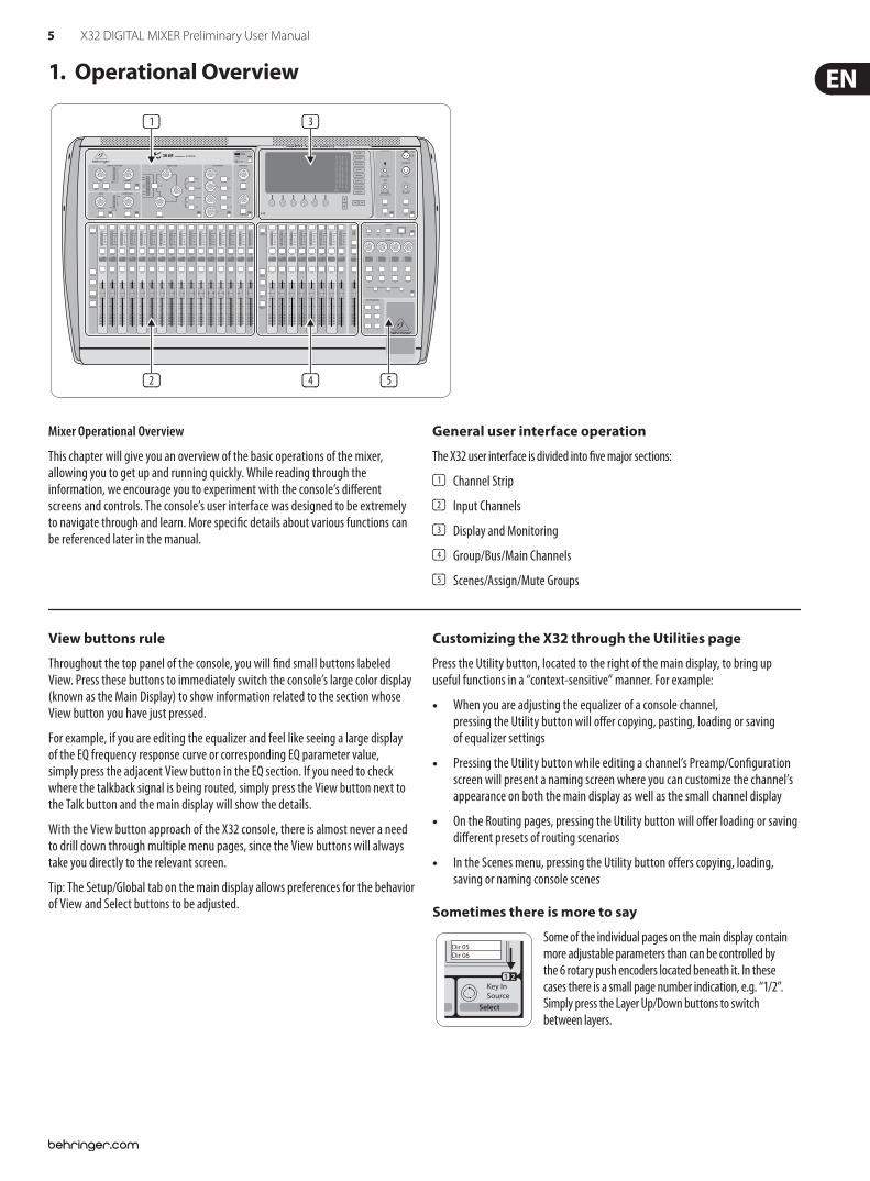
View buttons rule
Throughout the top panel of the console, you will $nd small buttons labeled View. Press these buttons to immediately switch the console’s large color display (known as the Main Display) to show information related to the section whose View button you have just pressed.
For example, if you are editing the equalizer and feel like seeing a large display of the EQ frequency response curve or corresponding EQ parameter value, simply press the adjacent View button in the EQ section. If you need to check where the talkback signal is being routed, simply press the View button next to the Talk button and the main display will show the details.
With the View button approach of the X32 console, there is almost never a need to drill down through multiple menu pages, since the View buttons will always take you directly to the relevant screen.
Tip: The Setup/Global tab on the main display allows preferences for the behavior of View and Select buttons to be adjusted.
Customizing the X32 through the Utilities page
Press the Utility button, located to the right of the main display, to bring up useful functions in a “context-sensitive” manner. For example:
When you are adjusting the equalizer of a console channel, pressing the Utility button will o!er copying, pasting, loading or saving of equalizer settings
Pressing the Utility button while editing a channel’s Preamp/Con$guration screen will present a naming screen where you can customize the channel’s appearance on both the main display as well as the small channel display
On the Routing pages, pressing the Utility button will o!er loading or saving di!erent presets of routing scenarios
In the Scenes menu, pressing the Utility button o!ers copying, loading, saving or naming console scenes
Sometimes there is more to say
Some of the individual pages on the main display contain more adjustable parameters than can be controlled by the 6 rotary push encoders located beneath it. In these cases there is a small page number indication, e.g. “1/2”. Simply press the Layer Up/Down buttons to switch between layers.
Dir 05Dir 06
Key InSource
Select
1 2
Mixer Operational Overview
This chapter will give you an overview of the basic operations of the mixer, allowing you to get up and running quickly. While reading through the information, we encourage you to experiment with the console’s di!erent screens and controls. The console’s user interface was designed to be extremely to navigate through and learn. More speci$c details about various functions can be referenced later in the manual.
General user interface operation
The X32 user interface is divided into $ve major sections:
(1) Channel Strip
(2) Input Channels
(3) Display and Monitoring
(4) Group/Bus/Main Channels
(5) Scenes/Assign/Mute Groups
6 X32 DIGITAL MIXER Preliminary User Manual
– 5
5
0
–10
10
– 20
– 30
– 40
– 50
– 60
– 00
– 5
5
0
–10
10
– 20
– 30
– 40
– 50
– 60
– 00
– 5
5
0
–10
10
– 20
– 30
– 40
– 50
– 60
– 00
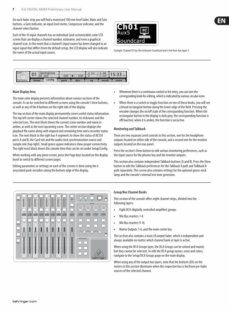
Input Channel Banks
You will $nd a select button on top of every channel that is used to direct the control focus of the user interface, including all channel related parameters (channel strip and main display), to that channel. Please note that at any time, there is exactly one channel selected (either Input Ch 1-32, Aux 1-8, FX Returns 1L-4R, Mix Bus 1-16, Main LR/C, or Matrix 1-6). DCA Groups (digitally controlled ampli$er) cannot be selected because they control a number of assigned channels rather than one speci$c channel.
The Input Channels section of the console is located on the left hand side, and o!ers 16 separate input channel strips. These 16 channel strips represent three separate layers of inputs for the console, including:
Input Channels 1-16
Input Channels 17-32
Auxiliary Inputs 1-6/USB playback/FX Returns 1L-4R
Press any of the correspondingly labeled layer buttons on the left side of the console to switch the input channel bank to any of the three layers listed above. The button will illuminate, reminding you which layer is active.
A fourth layer (Bus Masters) is also o!ered, allowing you to adjust the levels of the 16 Mix Bus Masters, which is useful when you wish to include Bus Masters into DCA Group assignments.
VIEWVIEWVIEWVIEW
VIEW
VIEW
VIEW
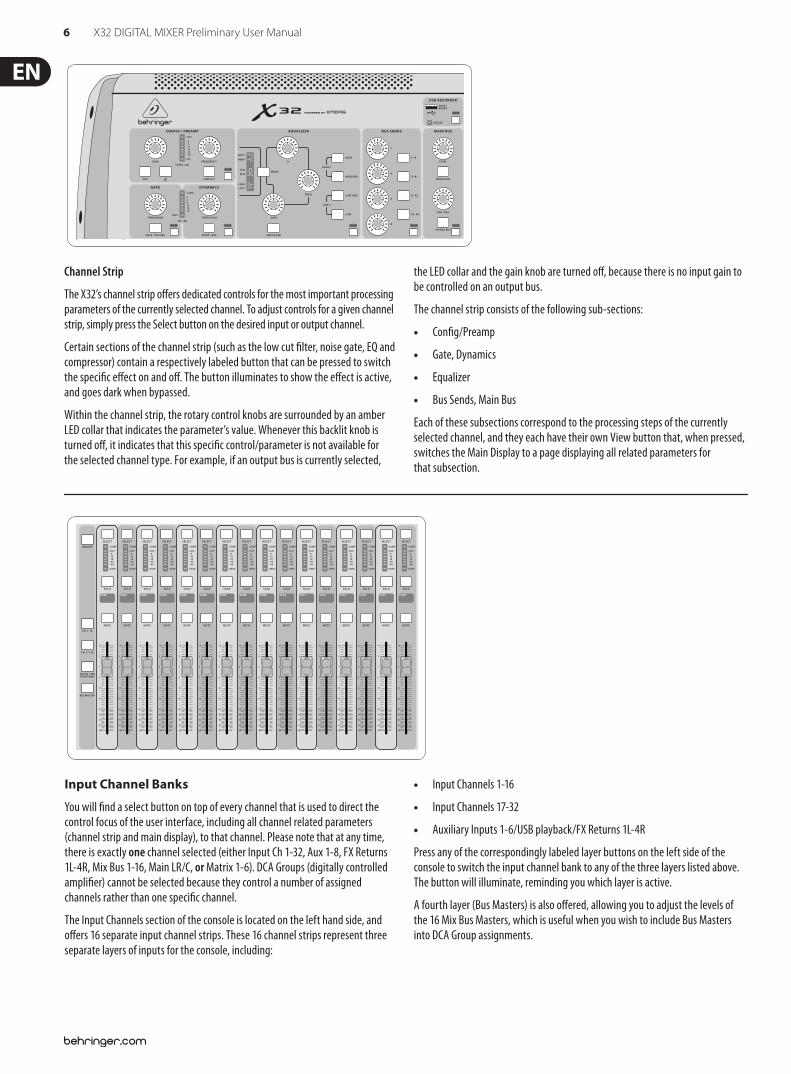
Channel Strip
The X32’s channel strip o!ers dedicated controls for the most important processing parameters of the currently selected channel. To adjust controls for a given channel strip, simply press the Select button on the desired input or output channel.
Certain sections of the channel strip (such as the low cut $lter, noise gate, EQ and compressor) contain a respectively labeled button that can be pressed to switch the speci$c e!ect on and o!. The button illuminates to show the e!ect is active, and goes dark when bypassed.
Within the channel strip, the rotary control knobs are surrounded by an amber LED collar that indicates the parameter’s value. Whenever this backlit knob is turned o!, it indicates that this speci$c control/parameter is not available for the selected channel type. For example, if an output bus is currently selected,
the LED collar and the gain knob are turned o!, because there is no input gain to be controlled on an output bus.
The channel strip consists of the following sub-sections:
Con$g/Preamp
Gate, Dynamics
Equalizer
Bus Sends, Main Bus
Each of these subsections correspond to the processing steps of the currently selected channel, and they each have their own View button that, when pressed, switches the Main Display to a page displaying all related parameters for that subsection.
7 X32 DIGITAL MIXER Preliminary User Manual
Ch01
FatSnare
OpeningScene02: next 0:00 - 0:00
A: S16 A: 48KB: - C: XUF : 1501 15:33
home con!g gate dyn eq sends main
Main Display Area
The main color display presents information about various sections of the console. It can be switched to di!erent screens using the console’s View buttons, as well as any of the 8 buttons on the right side of the display.
The top section of the main display permanently covers useful status information. The top left corner shows the selected channel number, its nickname and the selected icon. The next block shows the current scene number and name in amber, as well as the next upcoming scene. The center section displays the playback $le name along with elapsed and remaining time and a recorder status icon. The next block to the right has 4 segments to show the status of AES50 ports A and B, the Card slot and the audio clock synchronization source and sample rate (top right). Small green square indicators show proper connectivity. The right most block shows the console time that can be set under Setup/Con$g.
When working with any given screen, press the Page keys located on the display bezel to switch to di!erent screen pages.
Editing parameters or settings on each of the screens is done using the 6 associated push-encoders along the bottom edge of the display.
Whenever there is a continuous control or list entry, you can turn the corresponding knob for editing, which is indicated by various circular icons
When there is a switch or toggle function on one of these knobs, you will see a broad rectangular button along the lower edge of the $eld. Pressing the encoder changes the on/o! state of the corresponding function. When the rectangular button in the display is dark grey, the corresponding function is o!/inactive; when it is amber, the function is on/active
Monitoring and Talkback
There are two separate Level controls in this section, one for the headphone outputs located on either side of the console, and a second one for the monitor outputs located on the rear panel.
Press the section’s View button to edit various monitoring preferences, such as the input source for the phones bus and the monitor outputs.
This section also contains independent Talkback buttons (A and B). Press the View button to edit the Talkback preferences for the Talkback A path and Talkback B path separately. This screen also contains settings for the optional goose-neck lamp and the console’s internal test-tone generator.
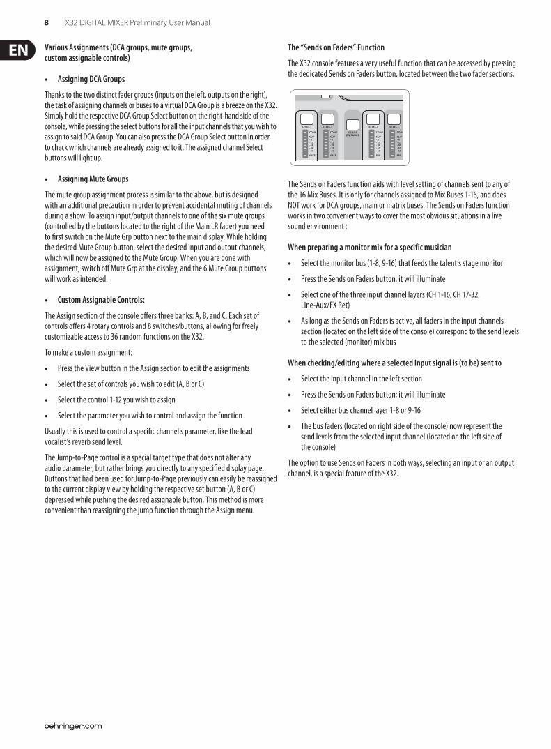
Group/Bus Channel Banks
This section of the console o!ers eight channel strips, divided into the following layers:
Eight DCA (digitally controlled ampli$er) groups
Mix Bus masters 1-8
Mix Bus masters 9-16
Matrix Outputs 1-6, and the main center bus
This section also contains a main LR output fader, which is independent and always available no matter which channel bank or layer is active.
When using the DCA Groups layer, the DCA Groups can be soloed and muted, but they cannot be selected. To edit the DCA group names, icons and colors, navigate to the Setup/DCA Groups page on the main display.
When using any of the output bus layers, note that the bottom LEDs on the meters in this section illuminate when the respective bus is fed from pre-fader sources of the selected channel.
VIEW
VIEW
– 6
On each fader strip you will $nd a motorized 100 mm level fader, Mute and Solo buttons, a Gate indicator, an input level meter, Compressor indicator, and the channel select button.
Each of the 16 input channels has an individual (and customizable) color LCD screen that can display a channel number, nickname, and even a graphical channel icon. In the event that a channel’s input source has been changed to an input signal that di!ers from the default setup, the LCD display will also indicate the name of the actual input source.
Ch01Aux5
Soundcard
PC
Example: Channel 01 has the nickname Soundcard and is fed from Aux input 5.
8 X32 DIGITAL MIXER Preliminary User Manual
Various Assignments (DCA groups, mute groups, custom assignable controls)
Assigning DCA Groups
Thanks to the two distinct fader groups (inputs on the left, outputs on the right), the task of assigning channels or buses to a virtual DCA Group is a breeze on the X32. Simply hold the respective DCA Group Select button on the right-hand side of the console, while pressing the select buttons for all the input channels that you wish to assign to said DCA Group. You can also press the DCA Group Select button in order to check which channels are already assigned to it. The assigned channel Select buttons will light up.
Assigning Mute Groups
The mute group assignment process is similar to the above, but is designed with an additional precaution in order to prevent accidental muting of channels during a show. To assign input/output channels to one of the six mute groups (controlled by the buttons located to the right of the Main LR fader) you need to $rst switch on the Mute Grp button next to the main display. While holding the desired Mute Group button, select the desired input and output channels, which will now be assigned to the Mute Group. When you are done with assignment, switch o! Mute Grp at the display, and the 6 Mute Group buttons will work as intended.
Custom Assignable Controls:
The Assign section of the console o!ers three banks: A, B, and C. Each set of controls o!ers 4 rotary controls and 8 switches/buttons, allowing for freely customizable access to 36 random functions on the X32.
To make a custom assignment:
Press the View button in the Assign section to edit the assignments
Select the set of controls you wish to edit (A, B or C)
Select the control 1-12 you wish to assign
Select the parameter you wish to control and assign the function
Usually this is used to control a speci$c channel’s parameter, like the lead vocalist’s reverb send level.
The Jump-to-Page control is a special target type that does not alter any audio parameter, but rather brings you directly to any speci$ed display page. Buttons that had been used for Jump-to-Page previously can easily be reassigned to the current display view by holding the respective set button (A, B or C) depressed while pushing the desired assignable button. This method is more convenient than reassigning the jump function through the Assign menu.
The “Sends on Faders” Function
The X32 console features a very useful function that can be accessed by pressing the dedicated Sends on Faders button, located between the two fader sections.
The Sends on Faders function aids with level setting of channels sent to any of the 16 Mix Buses. It is only for channels assigned to Mix Buses 1-16, and does NOT work for DCA groups, main or matrix buses. The Sends on Faders function works in two convenient ways to cover the most obvious situations in a live sound environment :
When preparing a monitor mix for a specific musician
Select the monitor bus (1-8, 9-16) that feeds the talent’s stage monitor
Press the Sends on Faders button; it will illuminate
Select one of the three input channel layers (CH 1-16, CH 17-32, Line-Aux/FX Ret)
As long as the Sends on Faders is active, all faders in the input channels section (located on the left side of the console) correspond to the send levels to the selected (monitor) mix bus
When checking/editing where a selected input signal is (to be) sent to
Select the input channel in the left section
Press the Sends on Faders button; it will illuminate
Select either bus channel layer 1-8 or 9-16
The bus faders (located on right side of the console) now represent the send levels from the selected input channel (located on the left side of the console)
The option to use Sends on Faders in both ways, selecting an input or an output channel, is a special feature of the X32.
VIEW
9 X32 DIGITAL MIXER Preliminary User Manual
Ch0101: 0:00 - 0:00
A: S16 A: 48KB: - C: XUF : 1901
home aux outanalog out p16 out card out aes50-a aes50-b
13:45
Inputs 1-8 Inputs 17-24Inputs 9-16Channel Processing Block Patch
Inputs 25-32 Aux In 1-4Connected Devices
Local In 1-8Local In 9-16Local In 17-24Local In 25-32AES50 A1-8AES50 A9-16AES50 A17-24AES50 A25-32AES50 A33-40AES50 A41-48AES50 B1-8AES50 B9-16AES50 B17-24AES50 A25-32
Local In 1-8Local In 9-16Local In 17-24Local In 25-32AES50 A1-8AES50 A9-16AES50 A17-24AES50 A25-32AES50 A33-40AES50 A41-48AES50 B1-8AES50 B9-16AES50 B17-24AES50 A25-32
Local In 1-8Local In 9-16Local In 17-24Local In 25-32AES50 A1-8AES50 A9-16AES50 A17-24AES50 A25-32AES50 A33-40AES50 A41-48AES50 B1-8AES50 B9-16AES50 B17-24AES50 A25-32
Local In 1-8Local In 9-16Local In 17-24Local In 25-32AES50 A1-8AES50 A9-16AES50 A17-24AES50 A25-32AES50 A33-40AES50 A41-48AES50 B1-8AES50 B9-16AES50 B17-24AES50 A25-32
Aux 1-4Local 1-4AES50 A1-4AES50 B1-4Card 1-4
AES50 A
AES50 B
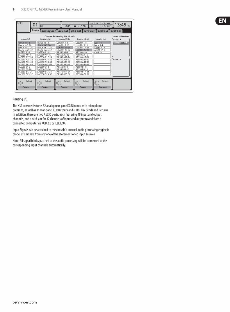
Routing I/O
The X32 console features 32 analog rear-panel XLR inputs with microphone-preamps, as well as 16 rear-panel XLR Outputs and 6 TRS Aux Sends and Returns. In addition, there are two AES50 ports, each featuring 48 input and output channels, and a card slot for 32 channels of input and output to and from a connected computer via USB 2.0 or IEEE1394.
Input Signals can be attached to the console’s internal audio processing engine in blocks of 8 signals from any one of the aforementioned input sources
Note: All signal blocks patched to the audio processing will be connected to the corresponding input channels automatically.
10 X32 DIGITAL MIXER Preliminary User Manual
Link Lo Cut
Ch0101:01 0:00 - 0:00
A: S16 A: 48KB: - C: XUF : 3714:11
-6-12-18-24-30-36-42-48-54
clip
home gate dyn eq sends maincon!g
Gain
Gain
48V In
Pre PostInsDelay
dB+0.00Link
Lo Cut
Lo Cut
Hz20Lo Cut
InputSelect
SourcePRE
Insert
Ins PosInsF
Connect
Insertms0.3
Delay
Delay
Delay
dB+0.0 Hz2.0
Reverse
t
ftmms
0.30.100.03
SourceOFFInput 01Input 02Input 03Input 04Input 05Input 06
InsertOFFInsFX 1LInsFX 1RInsFX 2LInsFX 2RInsFX 3LInsFX 3L
Insert Position
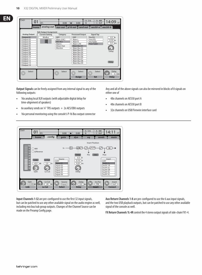
Input Channels 1-32 are pre-con$gured to use the $rst 32 input signals, but can be patched to use any other available signal on the audio engine as well, including mix bus/sub group outputs. Changes of the Channel Source can be made on the Preamp Con$g page.
Aux Return Channels 1-8 are pre-con$gured to use the 6 aux input signals, and the two USB playback outputs, but can be patched to use any other available signal of the console as well.
FX Return Channels 1L-4R control the 4 stereo output signals of side-chain FX1-4.
Delayms0.3
Set DelayAssign
ftmms
0.3
0.30.10
Delay
Delay
Select Select Select Select
Ch0101:01
home aux outanalog out p16 out card out aes50-a aes50-b
Analog Output CategoryCurrent SettingEdit Output Assignment
Processed Output Signal Tap
0:00 - 0:00A: S16 A: 48KB: - C: XUF : 3714:09
Output 01Output 02Output 03Output 04Output 05Output 06Output 07Output 08Output 09Output 10Output 11Output 12Output 13Output 14
MixBus OFFMain (LRC)Mix BusMatrixDirect OutMonitor
OFFMain LMain RMain C/MMain Bus 01Main Bus 02Main Bus 03Main Bus 04Main Bus 05Main Bus 06Main Bus 07Main Bus 08Main Bus 09
Pre EQPost EQPre FaderPost Fader
Output Signals can be freely assigned from any internal signal to any of the following outputs:
16x analog local XLR outputs (with adjustable digital delay for time-alignment of speakers)
6x auxiliary sends on ¼" TRS outputs + 2x AES/EBU outputs
16x personal monitoring using the console’s P-16 Bus output connector
Any and all of the above signals can also be mirrored in blocks of 8 signals on either one of
48x channels on AES50 port A
48x channels on AES50 port B
32x channels on USB/Firewire interface card
11 X32 DIGITAL MIXER Preliminary User Manual
Inputs
-6-12-18-24-30-36-42-48-54
clip
Link
GaindB00.00
Send Pos. Insert Pos. Insert
Link Bus Sends Insert ConnectPre
LeOnde.mp329 November 2010 Scene01
13:44:43 MyProj.prj00.05.00 00.00.00
home gate dyn eq sends maincon!g
Bus Con!guration Bus Insert Position
Insert
Ins 02
FX 01FX 02
Ins 01
...
Ins 03Ins 04
All Channel Sends Pre Con!guration
Inputs
Sub Grou
...
Post Fader
Pre EQPre Fader
Insert PostPre
"Channel Sends
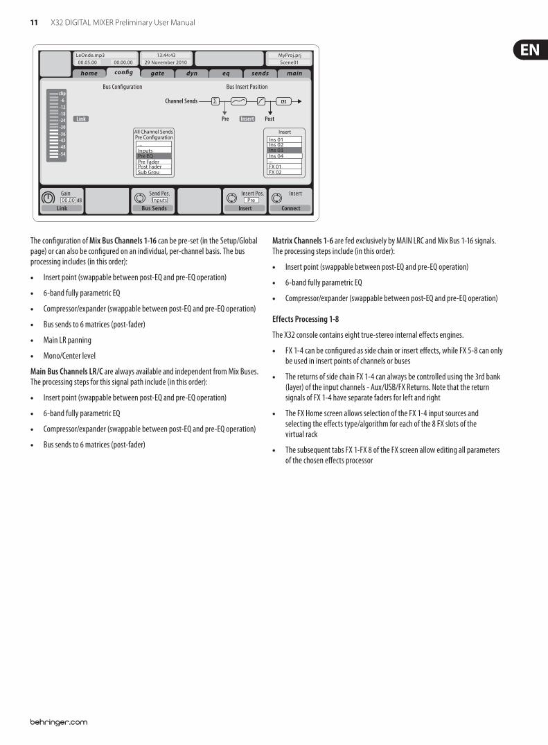
The con$guration of Mix Bus Channels 1-16 can be pre-set (in the Setup/Global page) or can also be con$gured on an individual, per-channel basis. The bus processing includes (in this order):
Insert point (swappable between post-EQ and pre-EQ operation)
6-band fully parametric EQ
Compressor/expander (swappable between post-EQ and pre-EQ operation)
Bus sends to 6 matrices (post-fader)
Main LR panning
Mono/Center level
Main Bus Channels LR/C are always available and independent from Mix Buses. The processing steps for this signal path include (in this order):
Insert point (swappable between post-EQ and pre-EQ operation)
6-band fully parametric EQ
Compressor/expander (swappable between post-EQ and pre-EQ operation)
Bus sends to 6 matrices (post-fader)
Matrix Channels 1-6 are fed exclusively by MAIN LRC and Mix Bus 1-16 signals. The processing steps include (in this order):
Insert point (swappable between post-EQ and pre-EQ operation)
6-band fully parametric EQ
Compressor/expander (swappable between post-EQ and pre-EQ operation)
Effects Processing 1-8
The X32 console contains eight true-stereo internal e!ects engines.
FX 1-4 can be con$gured as side chain or insert e!ects, while FX 5-8 can only be used in insert points of channels or buses
The returns of side chain FX 1-4 can always be controlled using the 3rd bank (layer) of the input channels - Aux/USB/FX Returns. Note that the return signals of FX 1-4 have separate faders for left and right
The FX Home screen allows selection of the FX 1-4 input sources and selecting the e!ects type/algorithm for each of the 8 FX slots of the virtual rack
The subsequent tabs FX 1-FX 8 of the FX screen allow editing all parameters of the chosen e!ects processor
12 X32 DIGITAL MIXER Preliminary User Manual
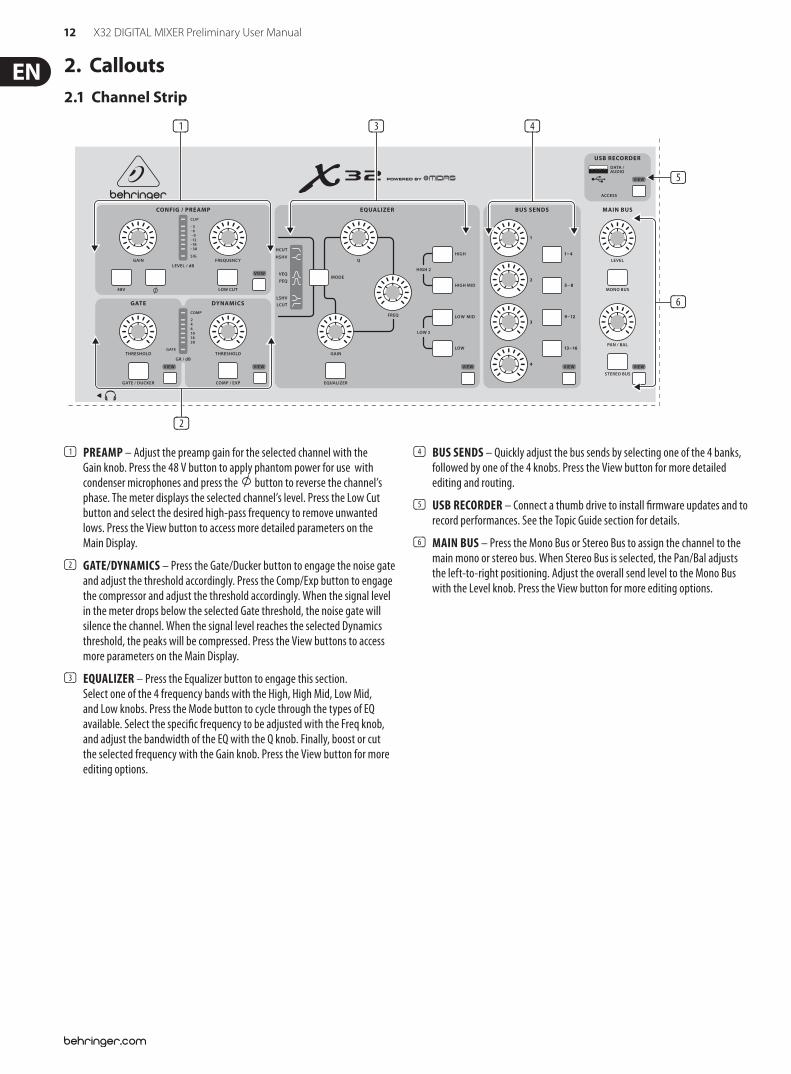
2. Callouts2.1 Channel Strip
VIEWVIEWVIEWVIEW
VIEW
VIEW
VIEW
(3)
(6)
(4)
(2)
(5)
(1)
(1) PREAMP – Adjust the preamp gain for the selected channel with the Gain knob. Press the 48 V button to apply phantom power for use with condenser microphones and press the button to reverse the channel’s phase. The meter displays the selected channel’s level. Press the Low Cut button and select the desired high-pass frequency to remove unwanted lows. Press the View button to access more detailed parameters on the Main Display.
(2) GATE/DYNAMICS – Press the Gate/Ducker button to engage the noise gate and adjust the threshold accordingly. Press the Comp/Exp button to engage the compressor and adjust the threshold accordingly. When the signal level in the meter drops below the selected Gate threshold, the noise gate will silence the channel. When the signal level reaches the selected Dynamics threshold, the peaks will be compressed. Press the View buttons to access more parameters on the Main Display.
(3) EQUALIZER – Press the Equalizer button to engage this section. Select one of the 4 frequency bands with the High, High Mid, Low Mid, and Low knobs. Press the Mode button to cycle through the types of EQ available. Select the speci$c frequency to be adjusted with the Freq knob, and adjust the bandwidth of the EQ with the Q knob. Finally, boost or cut the selected frequency with the Gain knob. Press the View button for more editing options.
(4) BUS SENDS – Quickly adjust the bus sends by selecting one of the 4 banks, followed by one of the 4 knobs. Press the View button for more detailed editing and routing.
(5) USB RECORDER – Connect a thumb drive to install $rmware updates and to record performances. See the Topic Guide section for details.
(6) MAIN BUS – Press the Mono Bus or Stereo Bus to assign the channel to the main mono or stereo bus. When Stereo Bus is selected, the Pan/Bal adjusts the left-to-right positioning. Adjust the overall send level to the Mono Bus with the Level knob. Press the View button for more editing options.
13 X32 DIGITAL MIXER Preliminary User Manual
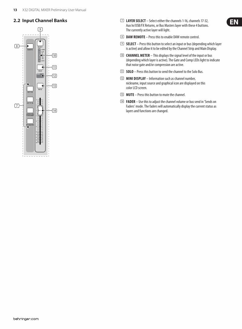
2.2 Input Channel Banks (7) LAYER SELECT – Select either the channels 1-16, channels 17-32, Aux In/USB/FX Returns, or Bus Masters layer with these 4 buttons. The currently active layer will light.
(8) DAW REMOTE – Press this to enable DAW remote control.
(9) SELECT – Press this button to select an input or bus (depending which layer is active) and allow it to be edited by the Channel Strip and Main Display.
(10) CHANNEL METER – This displays the signal level of the input or bus (depending which layer is active). The Gate and Comp LEDs light to indicate that noise gate and/or compression are active.
(11) SOLO – Press this button to send the channel to the Solo Bus.
(12) MINI DISPLAY – Information such as channel number, nickname, input source and graphical icon are displayed on this color LCD screen.
(13) MUTE – Press this button to mute the channel.
(14) FADER – Use this to adjust the channel volume or bus send in ’Sends on Faders’ mode. The faders will automatically display the current status as layers and functions are changed.
(9)
(8)
(10)
(11)
(12)
(13)
(14)(7)
14 X32 DIGITAL MIXER Preliminary User Manual
2.3 Display and Monitoring
VIEWVIEW
(16) (23)
(20)
(26)
(25)
(17) (22)
(27)
(21)(19)(18)
(15)
(24)
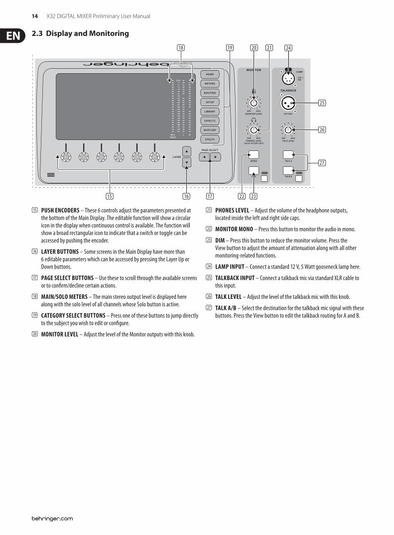
(15) PUSH ENCODERS – These 6 controls adjust the parameters presented at the bottom of the Main Display. The editable function will show a circular icon in the display when continuous control is available. The function will show a broad rectangular icon to indicate that a switch or toggle can be accessed by pushing the encoder.
(16) LAYER BUTTONS – Some screens in the Main Display have more than 6 editable parameters which can be accessed by pressing the Layer Up or Down buttons.
(17) PAGE SELECT BUTTONS – Use these to scroll through the available screens or to con$rm/decline certain actions.
(18) MAIN/SOLO METERS – The main stereo output level is displayed here along with the solo level of all channels whose Solo button is active.
(19) CATEGORY SELECT BUTTONS – Press one of these buttons to jump directly to the subject you wish to edit or con$gure.
(20) MONITOR LEVEL – Adjust the level of the Monitor outputs with this knob.
(21) PHONES LEVEL – Adjust the volume of the headphone outputs, located inside the left and right side caps.
(22) MONITOR MONO – Press this button to monitor the audio in mono.
(23) DIM – Press this button to reduce the monitor volume. Press the View button to adjust the amount of attenuation along with all other monitoring-related functions.
(24) LAMP INPUT – Connect a standard 12 V, 5 Watt gooseneck lamp here.
(25) TALKBACK INPUT – Connect a talkback mic via standard XLR cable to this input.
(26) TALK LEVEL – Adjust the level of the talkback mic with this knob.
(27) TALK A/B – Select the destination for the talkback mic signal with these buttons. Press the View button to edit the talkback routing for A and B.
15 X32 DIGITAL MIXER Preliminary User Manual
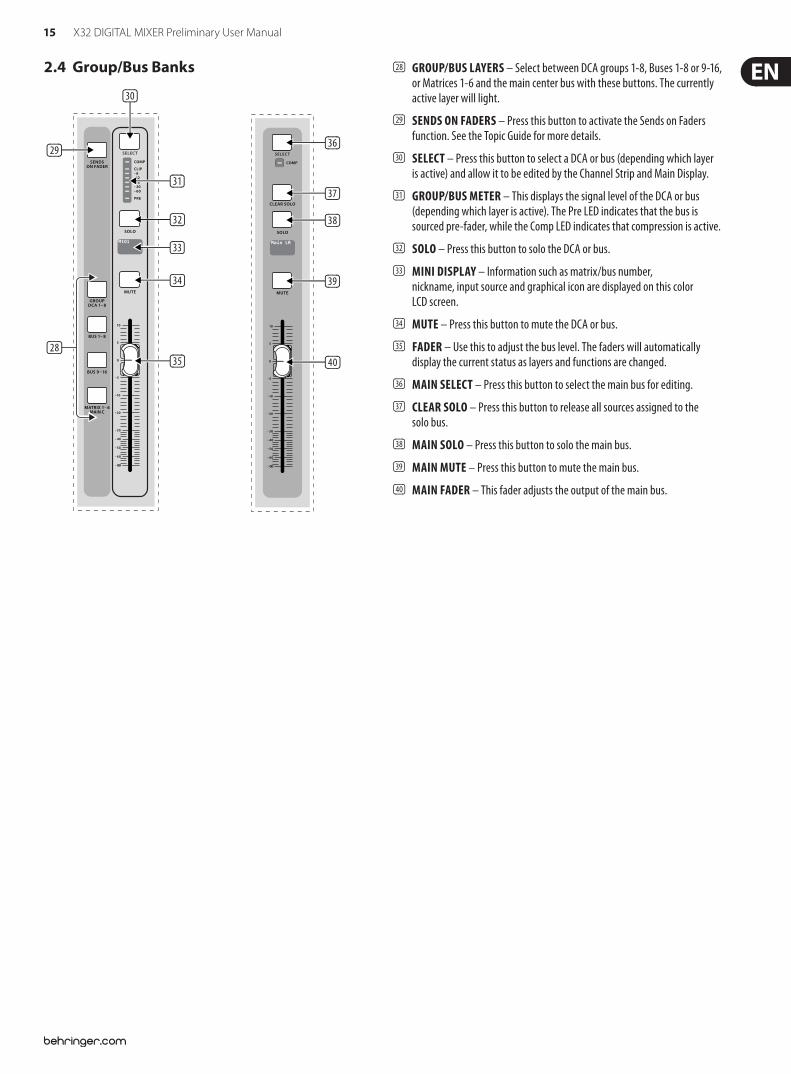
2.4 Group/Bus Banks (28) GROUP/BUS LAYERS – Select between DCA groups 1-8, Buses 1-8 or 9-16, or Matrices 1-6 and the main center bus with these buttons. The currently active layer will light.
(29) SENDS ON FADERS – Press this button to activate the Sends on Faders function. See the Topic Guide for more details.
(30) SELECT – Press this button to select a DCA or bus (depending which layer is active) and allow it to be edited by the Channel Strip and Main Display.
(31) GROUP/BUS METER – This displays the signal level of the DCA or bus (depending which layer is active). The Pre LED indicates that the bus is sourced pre-fader, while the Comp LED indicates that compression is active.
(32) SOLO – Press this button to solo the DCA or bus.
(33) MINI DISPLAY – Information such as matrix/bus number, nickname, input source and graphical icon are displayed on this color LCD screen.
(34) MUTE – Press this button to mute the DCA or bus.
(35) FADER – Use this to adjust the bus level. The faders will automatically display the current status as layers and functions are changed.
(36) MAIN SELECT – Press this button to select the main bus for editing.
(37) CLEAR SOLO – Press this button to release all sources assigned to the solo bus.
(38) MAIN SOLO – Press this button to solo the main bus.
(39) MAIN MUTE – Press this button to mute the main bus.
(40) MAIN FADER – This fader adjusts the output of the main bus.
(30)
(29)
(31)
(36)
(37)
(38)
(39)
(40)
(32)
(33)
(34)
(35)(28)
16 X32 DIGITAL MIXER Preliminary User Manual
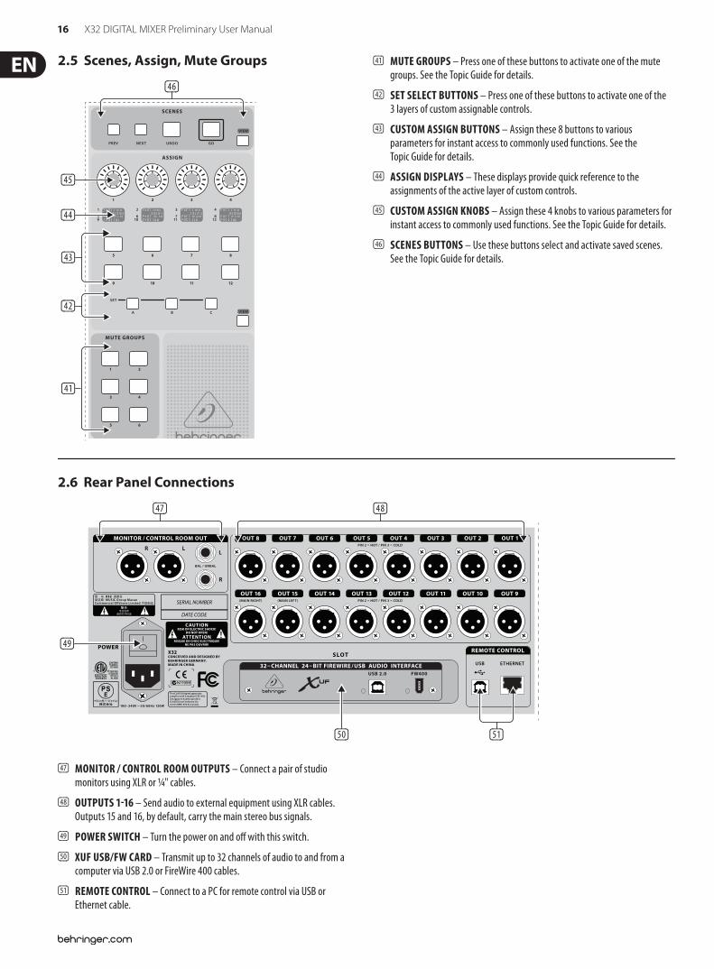
2.5 Scenes, Assign, Mute Groups (41) MUTE GROUPS – Press one of these buttons to activate one of the mute groups. See the Topic Guide for details.
(42) SET SELECT BUTTONS – Press one of these buttons to activate one of the 3 layers of custom assignable controls.
(43) CUSTOM ASSIGN BUTTONS – Assign these 8 buttons to various parameters for instant access to commonly used functions. See the Topic Guide for details.
(44) ASSIGN DISPLAYS – These displays provide quick reference to the assignments of the active layer of custom controls.
(45) CUSTOM ASSIGN KNOBS – Assign these 4 knobs to various parameters for instant access to commonly used functions. See the Topic Guide for details.
(46) SCENES BUTTONS – Use these buttons select and activate saved scenes. See the Topic Guide for details.
VIEW
VIEW
(45)
(44)
(43)
(42)
(41)
(46)
2.6 Rear Panel Connections
(50) (51)
(49)
(47) (48)
(47) MONITOR / CONTROL ROOM OUTPUTS – Connect a pair of studio monitors using XLR or ¼" cables.
(48) OUTPUTS 1!16 – Send audio to external equipment using XLR cables. Outputs 15 and 16, by default, carry the main stereo bus signals.
(49) POWER SWITCH – Turn the power on and o! with this switch.
(50) XUF USB/FW CARD – Transmit up to 32 channels of audio to and from a computer via USB 2.0 or FireWire 400 cables.
(51) REMOTE CONTROL – Connect to a PC for remote control via USB or Ethernet cable.
17 X32 DIGITAL MIXER Preliminary User Manual
(50) (51)
(49)
(56)
(52) (53) (54) (55)
(47) (48)
(57)
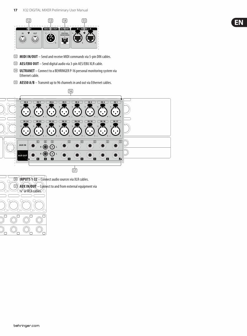
(52) MIDI IN/OUT – Send and receive MIDI commands via 5-pin DIN cables.
(53) AES/EBU OUT – Send digital audio via 3-pin AES/EBU XLR cable.
(54) ULTRANET – Connect to a BEHRINGER P-16 personal monitoring system via Ethernet cable.
(55) AES50 A/B – Transmit up to 96 channels in and out via Ethernet cables.
(56) INPUTS 1!32 – Connect audio sources via XLR cables.
(57) AUX IN/OUT – Connect to and from external equipment via ¼" or RCA cables.
(50) (51)
(49)
(56)
(52) (53) (54) (55)
(47) (48)
(57)
18 X32 DIGITAL MIXER Preliminary User Manual
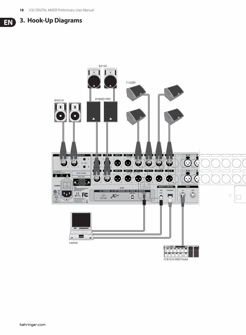
3. Hook-Up Diagrams
B1800D-PRO
B215D
F1320D
B3031A
Laptop
DI Box
GTX30
Keyboard
XM8500
2-TRACK HARD DISK RECORDER
FCB1010 MIDI Pedal
P-16 D
P-16 M
S16 Digital Snake
iPod
FX2000
HPX6000
(Sidecap output)
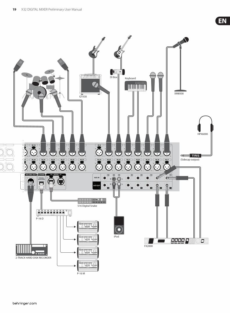
19 X32 DIGITAL MIXER Preliminary User Manual
B1800D-PRO
B215D
F1320D
B3031A
Laptop
DI Box
GTX30
Keyboard
XM8500
2-TRACK HARD DISK RECORDER
FCB1010 MIDI Pedal
P-16 D
P-16 M
S16 Digital Snake
iPod
FX2000
HPX6000
(Sidecap output)
20 X32 DIGITAL MIXER Preliminary User Manual
4. FX DescriptionsFX Descriptions
Here is a list and brief description of the e!ects available on the X32. When Stereo and Dual versions of an e!ect are o!ered, use the Stereo version when the left and right signal are to be altered together (e.g. on linked stereo channels or buses), or Dual when you want to dial di!erent settings for the left and right signal. See the Topic Guide for instructions on how to add e!ects to a channel or bus.
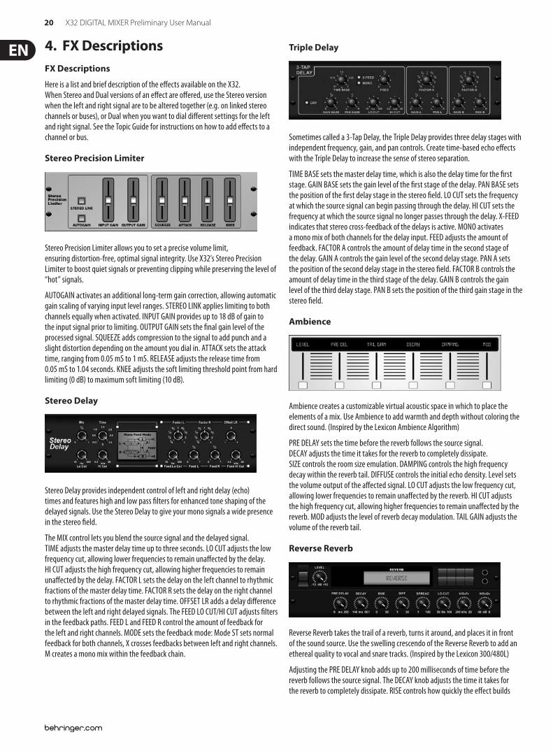
Stereo Precision Limiter
Stereo Precision Limiter allows you to set a precise volume limit, ensuring distortion-free, optimal signal integrity. Use X32’s Stereo Precision Limiter to boost quiet signals or preventing clipping while preserving the level of “hot” signals.
AUTOGAIN activates an additional long-term gain correction, allowing automatic gain scaling of varying input level ranges. STEREO LINK applies limiting to both channels equally when activated. INPUT GAIN provides up to 18 dB of gain to the input signal prior to limiting. OUTPUT GAIN sets the $nal gain level of the processed signal. SQUEEZE adds compression to the signal to add punch and a slight distortion depending on the amount you dial in. ATTACK sets the attack time, ranging from 0.05 mS to 1 mS. RELEASE adjusts the release time from 0.05 mS to 1.04 seconds. KNEE adjusts the soft limiting threshold point from hard limiting (0 dB) to maximum soft limiting (10 dB).
Stereo Delay
Stereo Delay provides independent control of left and right delay (echo) times and features high and low pass $lters for enhanced tone shaping of the delayed signals. Use the Stereo Delay to give your mono signals a wide presence in the stereo $eld.
The MIX control lets you blend the source signal and the delayed signal. TIME adjusts the master delay time up to three seconds. LO CUT adjusts the low frequency cut, allowing lower frequencies to remain una!ected by the delay. HI CUT adjusts the high frequency cut, allowing higher frequencies to remain una!ected by the delay. FACTOR L sets the delay on the left channel to rhythmic fractions of the master delay time. FACTOR R sets the delay on the right channel to rhythmic fractions of the master delay time. OFFSET LR adds a delay di!erence between the left and right delayed signals. The FEED LO CUT/HI CUT adjusts $lters in the feedback paths. FEED L and FEED R control the amount of feedback for the left and right channels. MODE sets the feedback mode: Mode ST sets normal feedback for both channels, X crosses feedbacks between left and right channels. M creates a mono mix within the feedback chain.
Triple Delay
Sometimes called a 3-Tap Delay, the Triple Delay provides three delay stages with independent frequency, gain, and pan controls. Create time-based echo e!ects with the Triple Delay to increase the sense of stereo separation.
TIME BASE sets the master delay time, which is also the delay time for the $rst stage. GAIN BASE sets the gain level of the $rst stage of the delay. PAN BASE sets the position of the $rst delay stage in the stereo $eld. LO CUT sets the frequency at which the source signal can begin passing through the delay. HI CUT sets the frequency at which the source signal no longer passes through the delay. X-FEED indicates that stereo cross-feedback of the delays is active. MONO activates a mono mix of both channels for the delay input. FEED adjusts the amount of feedback. FACTOR A controls the amount of delay time in the second stage of the delay. GAIN A controls the gain level of the second delay stage. PAN A sets the position of the second delay stage in the stereo $eld. FACTOR B controls the amount of delay time in the third stage of the delay. GAIN B controls the gain level of the third delay stage. PAN B sets the position of the third gain stage in the stereo $eld.
Ambience
Ambience creates a customizable virtual acoustic space in which to place the elements of a mix. Use Ambience to add warmth and depth without coloring the direct sound. (Inspired by the Lexicon Ambience Algorithm)
PRE DELAY sets the time before the reverb follows the source signal. DECAY adjusts the time it takes for the reverb to completely dissipate. SIZE controls the room size emulation. DAMPING controls the high frequency decay within the reverb tail. DIFFUSE controls the initial echo density. Level sets the volume output of the a!ected signal. LO CUT adjusts the low frequency cut, allowing lower frequencies to remain una!ected by the reverb. HI CUT adjusts the high frequency cut, allowing higher frequencies to remain una!ected by the reverb. MOD adjusts the level of reverb decay modulation. TAIL GAIN adjusts the volume of the reverb tail.
Reverse Reverb
Reverse Reverb takes the trail of a reverb, turns it around, and places it in front of the sound source. Use the swelling crescendo of the Reverse Reverb to add an ethereal quality to vocal and snare tracks. (Inspired by the Lexicon 300/480L)
Adjusting the PRE DELAY knob adds up to 200 milliseconds of time before the reverb follows the source signal. The DECAY knob adjusts the time it takes for the reverb to completely dissipate. RISE controls how quickly the e!ect builds
21 X32 DIGITAL MIXER Preliminary User Manual
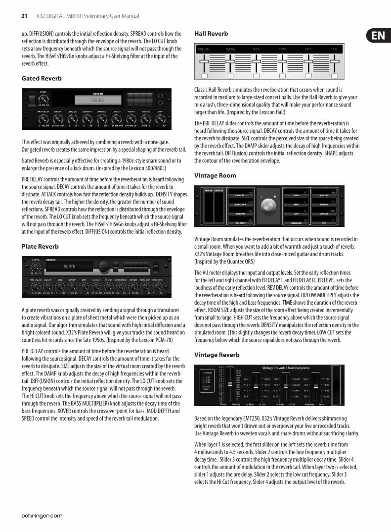
up. DIFF(USION) controls the initial re"ection density. SPREAD controls how the re"ection is distributed through the envelope of the reverb. The LO CUT knob sets a low frequency beneath which the source signal will not pass through the reverb. The HiSvFr/HiSvGn knobs adjust a Hi-Shelving $lter at the input of the reverb e!ect.
Gated Reverb
This e!ect was originally achieved by combining a reverb with a noise gate. Our gated reverb creates the same impression by a special shaping of the reverb tail.
Gated Reverb is especially e!ective for creating a 1980s-style snare sound or to enlarge the presence of a kick drum. (Inspired by the Lexicon 300/480L)
PRE DELAY controls the amount of time before the reverberation is heard following the source signal. DECAY controls the amount of time it takes for the reverb to dissipate. ATTACK controls how fast the re"ection density builds up. DENSITY shapes the reverb decay tail. The higher the density, the greater the number of sound re"ections. SPREAD controls how the re"ection is distributed through the envelope of the reverb. The LO CUT knob sets the frequency beneath which the source signal will not pass through the reverb. The HiSvFr/ HiSvGn knobs adjust a Hi-Shelving $lter at the input of the reverb e!ect. DIFF(USION) controls the initial re"ection density.
Plate Reverb
A plate reverb was originally created by sending a signal through a transducer to create vibrations on a plate of sheet metal which were then picked up as an audio signal. Our algorithm simulates that sound with high initial di!usion and a bright colored sound. X32’s Plate Reverb will give your tracks the sound heard on countless hit records since the late 1950s. (Inspired by the Lexicon PCM-70)
PRE DELAY controls the amount of time before the reverberation is heard following the source signal. DECAY controls the amount of time it takes for the reverb to dissipate. SIZE adjusts the size of the virtual room created by the reverb e!ect. The DAMP knob adjusts the decay of high frequencies within the reverb tail. DIFF(USION) controls the initial re"ection density. The LO CUT knob sets the frequency beneath which the source signal will not pass through the reverb. The HI CUT knob sets the frequency above which the source signal will not pass through the reverb. The BASS MULT(IPLIER) knob adjusts the decay time of the bass frequencies. XOVER controls the crossover point for bass. MOD DEPTH and SPEED control the intensity and speed of the reverb tail modulation.
Hall Reverb
Classic Hall Reverb simulates the reverberation that occurs when sound is recorded in medium to large-sized concert halls. Use the Hall Reverb to give your mix a lush, three-dimensional quality that will make your performance sound larger than life. (Inspired by the Lexicon Hall)
The PRE DELAY slider controls the amount of time before the reverberation is heard following the source signal. DECAY controls the amount of time it takes for the reverb to dissipate. SIZE controls the perceived size of the space being created by the reverb e!ect. The DAMP slider adjusts the decay of high frequencies within the reverb tail. DIFF(usion) controls the initial re"ection density. SHAPE adjusts the contour of the reverberation envelope.
Vintage Room
Vintage Room simulates the reverberation that occurs when sound is recorded in a small room. When you want to add a bit of warmth and just a touch of reverb, X32’s Vintage Room breathes life into close-miced guitar and drum tracks. (Inspired by the Quantec QRS)
The VU meter displays the input and output levels. Set the early re"ection times for the left and right channel with ER DELAY L and ER DELAY R. ER LEVEL sets the loudness of the early re"ection level. REV DELAY controls the amount of time before the reverberation is heard following the source signal. HI/LOW MULTIPLY adjusts the decay time of the high and bass frequencies. TIME shows the duration of the reverb e!ect. ROOM SIZE adjusts the size of the room e!ect being created incrementally from small to large. HIGH CUT sets the frequency above which the source signal does not pass through the reverb. DENSITY manipulates the re"ection density in the simulated room. (This slightly changes the reverb decay time). LOW CUT sets the frequency below which the source signal does not pass through the reverb.
Vintage Reverb
Based on the legendary EMT250, X32’s Vintage Reverb delivers shimmering bright reverb that won’t drown out or overpower your live or recorded tracks. Use Vintage Reverb to sweeten vocals and snare drums without sacri$cing clarity.
When layer 1 is selected, the $rst slider on the left sets the reverb time from 4 milliseconds to 4.5 seconds. Slider 2 controls the low frequency multiplier decay time. Slider 3 controls the high frequency multiplier decay time. Slider 4 controls the amount of modulation in the reverb tail. When layer two is selected, slider 1 adjusts the pre delay. Slider 2 selects the low cut frequency. Slider 3 selects the Hi Cut frequency. Slider 4 adjusts the output level of the reverb.
22 X32 DIGITAL MIXER Preliminary User Manual
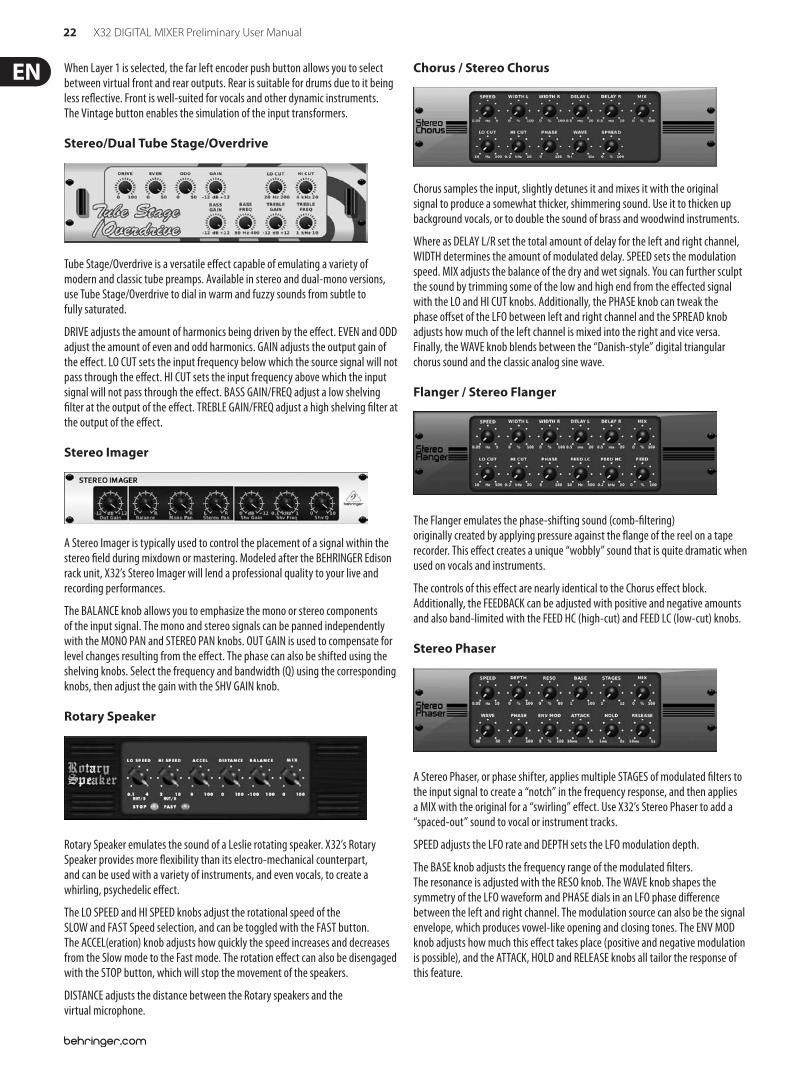
When Layer 1 is selected, the far left encoder push button allows you to select between virtual front and rear outputs. Rear is suitable for drums due to it being less re"ective. Front is well-suited for vocals and other dynamic instruments. The Vintage button enables the simulation of the input transformers.
Stereo/Dual Tube Stage/Overdrive
Tube Stage/Overdrive is a versatile e!ect capable of emulating a variety of modern and classic tube preamps. Available in stereo and dual-mono versions, use Tube Stage/Overdrive to dial in warm and fuzzy sounds from subtle to fully saturated.
DRIVE adjusts the amount of harmonics being driven by the e!ect. EVEN and ODD adjust the amount of even and odd harmonics. GAIN adjusts the output gain of the e!ect. LO CUT sets the input frequency below which the source signal will not pass through the e!ect. HI CUT sets the input frequency above which the input signal will not pass through the e!ect. BASS GAIN/FREQ adjust a low shelving $lter at the output of the e!ect. TREBLE GAIN/FREQ adjust a high shelving $lter at the output of the e!ect.
Stereo Imager
A Stereo Imager is typically used to control the placement of a signal within the stereo $eld during mixdown or mastering. Modeled after the BEHRINGER Edison rack unit, X32’s Stereo Imager will lend a professional quality to your live and recording performances.
The BALANCE knob allows you to emphasize the mono or stereo components of the input signal. The mono and stereo signals can be panned independently with the MONO PAN and STEREO PAN knobs. OUT GAIN is used to compensate for level changes resulting from the e!ect. The phase can also be shifted using the shelving knobs. Select the frequency and bandwidth (Q) using the corresponding knobs, then adjust the gain with the SHV GAIN knob.
Rotary Speaker
Rotary Speaker emulates the sound of a Leslie rotating speaker. X32’s Rotary Speaker provides more "exibility than its electro-mechanical counterpart, and can be used with a variety of instruments, and even vocals, to create a whirling, psychedelic e!ect.
The LO SPEED and HI SPEED knobs adjust the rotational speed of the SLOW and FAST Speed selection, and can be toggled with the FAST button. The ACCEL(eration) knob adjusts how quickly the speed increases and decreases from the Slow mode to the Fast mode. The rotation e!ect can also be disengaged with the STOP button, which will stop the movement of the speakers.
DISTANCE adjusts the distance between the Rotary speakers and the virtual microphone.
Chorus / Stereo Chorus
Chorus samples the input, slightly detunes it and mixes it with the original signal to produce a somewhat thicker, shimmering sound. Use it to thicken up background vocals, or to double the sound of brass and woodwind instruments.
Where as DELAY L/R set the total amount of delay for the left and right channel, WIDTH determines the amount of modulated delay. SPEED sets the modulation speed. MIX adjusts the balance of the dry and wet signals. You can further sculpt the sound by trimming some of the low and high end from the e!ected signal with the LO and HI CUT knobs. Additionally, the PHASE knob can tweak the phase o!set of the LFO between left and right channel and the SPREAD knob adjusts how much of the left channel is mixed into the right and vice versa. Finally, the WAVE knob blends between the “Danish-style” digital triangular chorus sound and the classic analog sine wave.
Flanger / Stereo Flanger
The Flanger emulates the phase-shifting sound (comb-$ltering) originally created by applying pressure against the "ange of the reel on a tape recorder. This e!ect creates a unique “wobbly” sound that is quite dramatic when used on vocals and instruments.
The controls of this e!ect are nearly identical to the Chorus e!ect block. Additionally, the FEEDBACK can be adjusted with positive and negative amounts and also band-limited with the FEED HC (high-cut) and FEED LC (low-cut) knobs.
Stereo Phaser
A Stereo Phaser, or phase shifter, applies multiple STAGES of modulated $lters to the input signal to create a “notch” in the frequency response, and then applies a MIX with the original for a “swirling” e!ect. Use X32’s Stereo Phaser to add a “spaced-out” sound to vocal or instrument tracks.
SPEED adjusts the LFO rate and DEPTH sets the LFO modulation depth.
The BASE knob adjusts the frequency range of the modulated $lters. The resonance is adjusted with the RESO knob. The WAVE knob shapes the symmetry of the LFO waveform and PHASE dials in an LFO phase di!erence between the left and right channel. The modulation source can also be the signal envelope, which produces vowel-like opening and closing tones. The ENV MOD knob adjusts how much this e!ect takes place (positive and negative modulation is possible), and the ATTACK, HOLD and RELEASE knobs all tailor the response of this feature.
23 X32 DIGITAL MIXER Preliminary User Manual
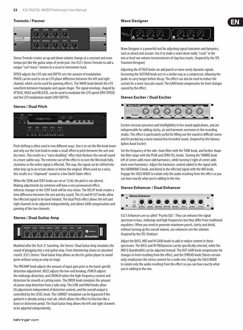
Tremolo / Panner
Stereo Tremolo creates an up and down volume change at a constant and even tempo just like the guitar amps of yesteryear. Use X32’s Stereo Tremolo to add a unique “surf-music” texture to a vocal or instrument track.
SPEED adjusts the LFO rate and DEPTH sets the amount of modulation. PHASE can be used to set an LFO phase di!erence between the left and right channel, which can be used for panning e!ects. The WAVE knob blends the LFO waveform between triangular and square shape. The signal envelope, shaped by ATTACK, HOLD and RELEASE, can be used to modulate the LFO speed (ENV SPEED) and the LFO modulation depth (ENV DEPTH).
Stereo / Dual Pitch
Pitch shifting is often used in two di!erent ways. One is to set the Mix knob lower and only use the Cent knob to make a small o!set in pitch between the wet and dry tones. This results in a “voice doubling” e!ect that thickens the overall sound in a more subtle way. The extreme use of the e!ect is to turn the Mix knob fully-clockwise so the entire signal is e!ected. This way, the signal can be shifted into other keys up to an octave above or below the original. When used on a voice, this results in a “chipmunk” sound or a low Darth Vader e!ect.
When the SEMI and CENT knobs are set at 12:00, the pitch is not altered. Making adjustments by semitone will have a very pronounced e!ect, whereas changes to the CENT knob will be very minor. The DELAY knob creates a time di!erence between the wet and dry sound. The LO and HI CUT knobs allow the e!ected signal to be band-limited. The Dual Pitch e!ect allows the left and right channels to be adjusted independently, and allows GAIN compensation and panning of the two channels.
Stereo / Dual Guitar Amp
Modeled after the Tech 21 SansAmp, the Stereo / Dual Guitar Amp simulates the sound of plugging into a real guitar amp. From shimmering cleans to saturated crunch, X32’s Stereo / Dual Guitar Amp allows an electric guitar player to sound great without using an amp on stage.
The PREAMP knob adjusts the amount of input gain prior to the band-speci$c distortion adjustment. BUZZ adjusts the low-end breakup, PUNCH adjusts the midrange distortion, and CRUNCH tailors the high-frequency content and distortion for smooth or cutting notes. The DRIVE knob simulates the amount of power amp distortion from a tube amp. The LOW and HIGH knobs allow EQ adjustment independent of distortion content, and the overall output is controlled by the LEVEL knob. The CABINET simulation can be bypassed if the guitarist is already using a real cab, which allows the e!ect to function like a boost or distortion pedal. The Dual Guitar Amp allows the left and right channels to be adjusted independently.
Wave Designer
Wave Designer is a powerful tool for adjusting signal transients and dynamics, such as attack and sustain. Use it to make a snare drum really “crack” in the mix or level out volume inconsistencies of slap bass tracks. (Inspired by the SPL Transient Designer)
Adjusting the ATTACK knob can add punch or tame overly dynamic signals. Increasing the SUSTAIN knob acts in a similar way as a compressor, allowing the peaks to carry longer before decay. The e!ect can also be used to reduce the sustain for a more staccato sound. The GAIN knob compensates for level changes caused by the e!ect.
Stereo Exciter / Dual Exciter
Exciters increase presence and intelligibility in live sound applications, and are indispensable for adding clarity, air and harmonic overtones in the recording studio. This e!ect is particularly useful for $lling out the sound in di&cult rooms and for producing a more natural live/recorded sound. (Inspired by the famous Aphex Aural Exciter)
Set the frequency of the side-chain $lter with the TUNE knob, and further shape the $lter slope with the PEAK and ZERO FILL knobs. Turning the TIMBRE knob left of center adds more odd harmonics, while turning it right of center adds more even harmonics. Adjust the harmonic content added to the signal with the HARMONICS knob, and blend in the e!ected signal with the MIX knob. Engage the SOLO MODE to isolate only the audio resulting from the e!ect so you can hear exactly what you’re adding to the mix.
Stereo Enhancer / Dual Enhancer
X32’s Enhancers are so called “Psycho EQs”. They can enhance the signal spectrum in bass, midrange and high frequencies but they di!er from traditional equalizers. When you need to generate maximum punch, clarity and detail, without turning up the overall volume, our enhancers are the solution. (Inspired by the SPL Vitalizer)
Adjust the BASS, MID and HI GAIN knobs to add or reduce content in those spectrums. The BASS and HI FREQuencies can be speci$cally selected, while the MID Q (bandwidth) can be adjusted instead. The OUT GAIN knob compensates for changes in level resulting from the e!ect, and the SPREAD knob (Stereo version only) emphasizes the stereo content for a wider mix. Engage the SOLO MODE to isolate only the audio resulting from the e!ect so you can hear exactly what you’re adding to the mix.
24 X32 DIGITAL MIXER Preliminary User Manual
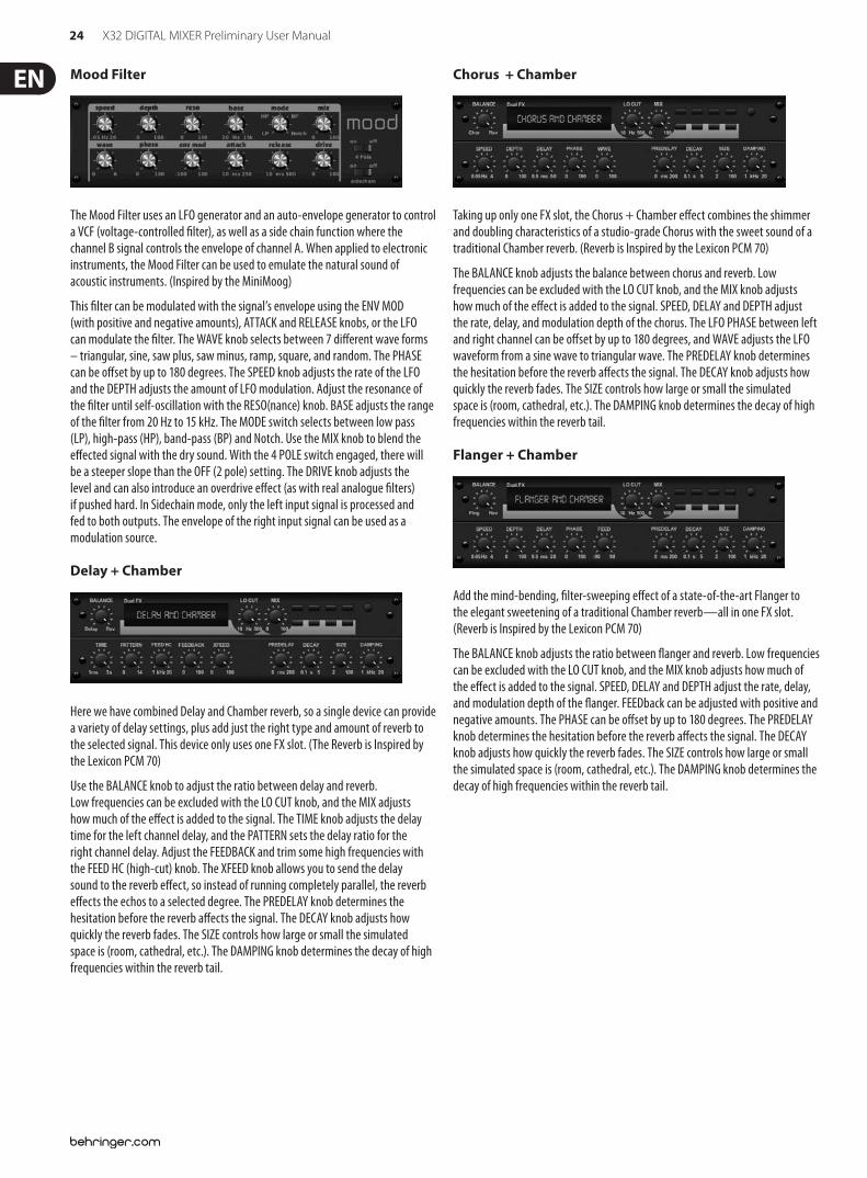
Mood Filter
The Mood Filter uses an LFO generator and an auto-envelope generator to control a VCF (voltage-controlled $lter), as well as a side chain function where the channel B signal controls the envelope of channel A. When applied to electronic instruments, the Mood Filter can be used to emulate the natural sound of acoustic instruments. (Inspired by the MiniMoog)
This $lter can be modulated with the signal’s envelope using the ENV MOD (with positive and negative amounts), ATTACK and RELEASE knobs, or the LFO can modulate the $lter. The WAVE knob selects between 7 di!erent wave forms – triangular, sine, saw plus, saw minus, ramp, square, and random. The PHASE can be o!set by up to 180 degrees. The SPEED knob adjusts the rate of the LFO and the DEPTH adjusts the amount of LFO modulation. Adjust the resonance of the $lter until self-oscillation with the RESO(nance) knob. BASE adjusts the range of the $lter from 20 Hz to 15 kHz. The MODE switch selects between low pass (LP), high-pass (HP), band-pass (BP) and Notch. Use the MIX knob to blend the e!ected signal with the dry sound. With the 4 POLE switch engaged, there will be a steeper slope than the OFF (2 pole) setting. The DRIVE knob adjusts the level and can also introduce an overdrive e!ect (as with real analogue $lters) if pushed hard. In Sidechain mode, only the left input signal is processed and fed to both outputs. The envelope of the right input signal can be used as a modulation source.
Delay + Chamber
Here we have combined Delay and Chamber reverb, so a single device can provide a variety of delay settings, plus add just the right type and amount of reverb to the selected signal. This device only uses one FX slot. (The Reverb is Inspired by the Lexicon PCM 70)
Use the BALANCE knob to adjust the ratio between delay and reverb. Low frequencies can be excluded with the LO CUT knob, and the MIX adjusts how much of the e!ect is added to the signal. The TIME knob adjusts the delay time for the left channel delay, and the PATTERN sets the delay ratio for the right channel delay. Adjust the FEEDBACK and trim some high frequencies with the FEED HC (high-cut) knob. The XFEED knob allows you to send the delay sound to the reverb e!ect, so instead of running completely parallel, the reverb e!ects the echos to a selected degree. The PREDELAY knob determines the hesitation before the reverb a!ects the signal. The DECAY knob adjusts how quickly the reverb fades. The SIZE controls how large or small the simulated space is (room, cathedral, etc.). The DAMPING knob determines the decay of high frequencies within the reverb tail.
Chorus + Chamber
Taking up only one FX slot, the Chorus + Chamber e!ect combines the shimmer and doubling characteristics of a studio-grade Chorus with the sweet sound of a traditional Chamber reverb. (Reverb is Inspired by the Lexicon PCM 70)
The BALANCE knob adjusts the balance between chorus and reverb. Low frequencies can be excluded with the LO CUT knob, and the MIX knob adjusts how much of the e!ect is added to the signal. SPEED, DELAY and DEPTH adjust the rate, delay, and modulation depth of the chorus. The LFO PHASE between left and right channel can be o!set by up to 180 degrees, and WAVE adjusts the LFO waveform from a sine wave to triangular wave. The PREDELAY knob determines the hesitation before the reverb a!ects the signal. The DECAY knob adjusts how quickly the reverb fades. The SIZE controls how large or small the simulated space is (room, cathedral, etc.). The DAMPING knob determines the decay of high frequencies within the reverb tail.
Flanger + Chamber
Add the mind-bending, $lter-sweeping e!ect of a state-of-the-art Flanger to the elegant sweetening of a traditional Chamber reverb—all in one FX slot. (Reverb is Inspired by the Lexicon PCM 70)
The BALANCE knob adjusts the ratio between "anger and reverb. Low frequencies can be excluded with the LO CUT knob, and the MIX knob adjusts how much of the e!ect is added to the signal. SPEED, DELAY and DEPTH adjust the rate, delay, and modulation depth of the "anger. FEEDback can be adjusted with positive and negative amounts. The PHASE can be o!set by up to 180 degrees. The PREDELAY knob determines the hesitation before the reverb a!ects the signal. The DECAY knob adjusts how quickly the reverb fades. The SIZE controls how large or small the simulated space is (room, cathedral, etc.). The DAMPING knob determines the decay of high frequencies within the reverb tail.
25 X32 DIGITAL MIXER Preliminary User Manual
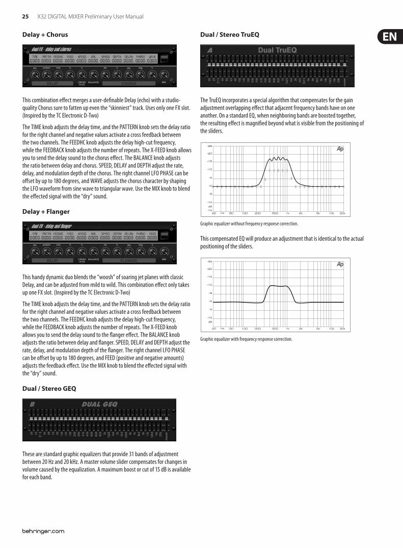
Delay + Chorus
This combination e!ect merges a user-de$nable Delay (echo) with a studio-quality Chorus sure to fatten up even the “skinniest” track. Uses only one FX slot. (Inspired by the TC Electronic D-Two)
The TIME knob adjusts the delay time, and the PATTERN knob sets the delay ratio for the right channel and negative values activate a cross feedback between the two channels. The FEEDHC knob adjusts the delay high-cut frequency, while the FEEDBACK knob adjusts the number of repeats. The X-FEED knob allows you to send the delay sound to the chorus e!ect. The BALANCE knob adjusts the ratio between delay and chorus. SPEED, DELAY and DEPTH adjust the rate, delay, and modulation depth of the chorus. The right channel LFO PHASE can be o!set by up to 180 degrees, and WAVE adjusts the chorus character by shaping the LFO waveform from sine wave to triangular wave. Use the MIX knob to blend the e!ected signal with the “dry” sound.
Delay + Flanger
This handy dynamic duo blends the “woosh” of soaring jet planes with classic Delay, and can be adjusted from mild to wild. This combination e!ect only takes up one FX slot. (Inspired by the TC Electronic D-Two)
The TIME knob adjusts the delay time, and the PATTERN knob sets the delay ratio for the right channel and negative values activate a cross feedback between the two channels. The FEEDHC knob adjusts the delay high-cut frequency, while the FEEDBACK knob adjusts the number of repeats. The X-FEED knob allows you to send the delay sound to the "anger e!ect. The BALANCE knob adjusts the ratio between delay and "anger. SPEED, DELAY and DEPTH adjust the rate, delay, and modulation depth of the "anger. The right channel LFO PHASE can be o!set by up to 180 degrees, and FEED (positive and negative amounts) adjusts the feedback e!ect. Use the MIX knob to blend the e!ected signal with the “dry” sound.
Dual / Stereo GEQ
These are standard graphic equalizers that provide 31 bands of adjustment between 20 Hz and 20 kHz. A master volume slider compensates for changes in volume caused by the equalization. A maximum boost or cut of 15 dB is available for each band.
Dual / Stereo TruEQ
The TruEQ incorporates a special algorithm that compensates for the gain adjustment overlapping e!ect that adjacent frequency bands have on one another. On a standard EQ, when neighboring bands are boosted together, the resulting e!ect is magni$ed beyond what is visible from the positioning of the sliders.
Graphic equalizer without frequency response correction.
This compensated EQ will produce an adjustment that is identical to the actual positioning of the sliders.
Graphic equalizer with frequency response correction.
26 X32 DIGITAL MIXER Preliminary User Manual
5. Topic Guide5.1 Starting up, shutting down, and !rmware updatesWe recommend switching the X32 on before any active sound reinforcement system is connected. The function called “Safe Main Levels”, located in the Setup/General Preferences screen, automatically turns down the main LRC bus levels when booting the console, and also prevents any scene loading actions from a!ecting (speci$cally turning up) the main levels.
Synchronization and Sample Rate settings can also be adjusted on the Setup/Con$g page, but please note that changing the sample rate will require a console reboot.
◊ Please Note: Settings under ‘Link Preferences’, ‘Panning Mode’, and ‘DCA groups’ are stored with the Scene data while all other settings made on the Setup/Config page are not stored in any preset and will not be initialized either. Please verify before using the X32 that the sample rate is set correctly and if the synchronization source is selected appropriately. If set to external synchronization via one of the two AES50 ports, while no clock source is actually connected or switched on, then the corresponding small square icon in the main display’s top row would be red rather than green. In normal state you should only see 1-4 green squares in the top section depending on the units connected.
Note that if the X32 console has previously been in use by somebody else, and you feel unsure about its actual status, you can reset it to default settings in either of two convenient ways:
1. While the console is booting up and the “X32” logo appears on the screen, press and hold the “Scenes / UNDO” button, keeping it depressed until the console is fully operational and the Home screen is displayed. The console will now be in the exact same state as it was when $rst shipped from the factory. However, you can immediately revert back to the status the console was in before being switched o! by pressing the Scenes/UNDO button.
2. You can also reset the console any time after booting by pressing “Setup/Con$g” -> “Initialize”.
The X32 regularly stores the console’s status to its onboard "ash memory, so there is usually nothing wrong with switching it o!, and you do not have to explicitly save the current status. However, when a large number of parameters have been recently changed, storing all of them to "ash can take up to 1 minute, in a “worst-case” scenario. In order to prevent any errors by losing power during this type of storage operation, we recommend using the “Safe Shutdown” function from the Setup/Global page, an operation similar to un-mounting a USB thumb-drive from your PC.
Updates:
The X32 $rmware can easily be updated by plugging a USB stick into the top panel USB connector after a $rmware update $le has been downloaded and stored on the root level of the attached drive. Simply insert the USB drive while the console is turned o!, then power on the console. While booting, the X32 will run a fully automatic $rmware update, which might take 2-3 minutes longer than the regular boot sequence.
The USB socket is not suitable for other non-memory USB devices like keyboards, mice, lamps, etc.
5.2 Default setup for connecting to monitoring and P.A. systemsThe X32 comes pre-con$gured with the local XLR inputs connected to input channels 1-32, and XLR outputs 1-14 connected to the mix bus masters 1-14. Bus masters 13-16 are connected to the e!ects inputs FX1-4. The Main LR (stereo) signal is normally put out on XLR outputs 15/16.
The Monitoring outputs on ¼" and XLR connectors, and the two Phones outputs (in the side-cap handles) always carry either the Monitor Source signal or any solo signal, whenever a solo button is active. Press the View button in the Monitor section to check or change the solo and monitoring preferences.
1. Power up the X32 console $rst, before any connected power amps or speakers are switched on.
2. Connect cables to XLR outputs 15 and 16 on the rear panel, connecting the other ends of the cables to the inputs of your P.A. system. These normally carry the main stereo bus left and right.
3. All buses or input channels that are to be put out on the main PA system must have their Stereo Bus switches on. Use the selected channel’s pan control to place the signal within the main stereo $eld, and the channel’s fader to set the volume.
4. Use the rear panel Monitoring outputs to connect monitor speakers or, if you prefer, use the ¼" outputs in the sidecaps to connect your head phones. You will either hear the monitor source signal, which is Main Stereo by default, or any channel with its solo button being active.
5.3 How do I connect a microphone, process its signal and send it out to the P.A. system?1. Press the Select button of a desired input channel (for example, channel 1 on
the “Channels 1-16” input layer) and make sure the channel fader is down.
2. In the channel processing section in the upper left hand corner, make sure the phantom power is switched o!.
3. Connect a microphone to XLR input 1 on the X32’s rear panel.
4. Press the 48V button to switch phantom power on for channel 1 (if the microphone requires it, such as a condenser microphone).
5. Use the Gain control to adjust the gain level as necessary, using the input meter as a guide.
6. Switch on and adjust the Low Cut $lter as needed to remove rumble or wind noise.
7. Adjust the channel equalizer controls to sculpt the sound quality of the microphone signal.
8. Adjust the channel Gate and Compressor controls as desired. Note that by pressing the “view” button in the compressor or gate section, the main screen will switch to the compressor or gate display for the selected channel, o!ering additional compressor or gate controls beyond the dedicated top-panel controls.
9. Turn on the “Stereo Bus” switch in order to route the selected signal to the main LR, then adjust the Pan control to place the signal within the stereo $eld.
10. Adjust the Channel 1 fader to the 0 dB region, then slowly turn up the main LR fader until you hear the mic signal ampli$ed through your P.A. system.
27 X32 DIGITAL MIXER Preliminary User Manual
5.4 How do I add one of the 8 internal e#ects to the sound?There are two types of e!ects that are commonly used:
“E!ects Loop” (side chain) style e!ects, where multiple channels all send varying amounts of their signal to a common e!ect, such as a reverb, delay, or chorus.
“Insert” style e!ects that are inserted in to the signal path of a single channel of audio. Examples would be a graphic EQ, $lter, exciter, or tube emulator.
To apply an “E!ects Loop” style e!ect:
Press the “FX” menu button. The main screen will show the FX home screen where di!erent e!ects processors are assigned to the 8 processing slots.
Adjust rotary encoder #6 to highlight the $rst e!ects processor; it will be surrounded by an orange outline.
Adjust rotary encoder #1 and rotary encoder #2, selecting your desired bus as the source for both the left and right inputs of the $rst e!ect processor. By default, FX 1 is sourced from Bus 13.
Adjust rotary encoder #5 to select a speci$c e!ect processor, such as “Ambience”.
Select the fader bank button labeled “RTN” on the left side of the console. Bring the faders labeled FX1L and FX1R up to 0 dB in case they are not set to this value by default. In the initial setup, these returns are stereo linked and automatically send to the main LR bus, but it is also possible to send them to the other buses as well. For this, press the HOME button next to the screen while the return is selected, then go to the SENDS tab with the PAGE SELECT right button and adjust the send levels for the return to the other buses, or use the dedicated BUS SENDS controls.
Back on the EFFECTS page, press the PAGE SELECT right button to switch the screen to the editor for the Ambience processor. The screen will switch to an editor page for the $rst processor. Adjust the rotary encoders to tailor the e!ect to your liking.
To apply the e!ect to assorted input channels, select an input channel, then adjust its “Bus Send 13” knob to taste. As the bus send level is increased, more of the channel signal will be sent to the Ambience e!ect. Repeat this process with other channels you wish to send to the Ambience processor.
To apply an “insert” style e!ect:
Press the “EFFECTS” menu button.
As the e!ects on the left side are also able to handle complex send e!ects like reverb, the slots on the right side shall be used for insert e!ects like limiter, graphic EQ, etc. You can also use insert e!ects on the left side, but this will limit your use of reverbs and other processor-intensive e!ects.
Adjust rotary encoder #6 to highlight one of the e!ects processors on the right side; it will be surrounded by an orange outline.
Adjust rotary encoder #1 and rotary encoder #2, selecting “Insert” as the source for both the left and right inputs of the e!ect processor.
Adjust rotary encoder #5 to select a speci$c e!ect processor, such as “precision limiter”.
Select the speci$c input or output channel you wish to use the inserted e!ect on.
Press the HOME button, then the PAGE SELECT right button to navigate to the selected channel’s “Con$g” screen.
Adjust rotary control #6 to select the speci$c processor you have applied the e!ect to, in this case “Ins FX 5L”. Press the encoder to connect the selected insert e!ect.
The Precision Limiter is now applied as an insert on the selected channel. Sending more than one channel through the same insert e!ect is, of course, prohibited. There will be a warning when you try to insert an e!ect slot that has already been used as an insert on any other channel. Both sides of a dual type e!ect can be used as inserts on di!erent channels or buses.
5.5 How do I use an outboard e#ects processor?In some situations, you may wish to use a loop-style e!ect provided by an external e!ect processor, as opposed to using one of the eight built-in processors. To do so:
Press the ROUTE button, page right to the “Aux Out” screen, and adjust the $rst and fourth encoders to tie a rear panel ¼" aux out, such as Aux Out 1, to an available mix bus, such as Mix Bus 2.
Patch rear panel Aux Output 1 to the input of your external e!ects processor.
Patch the output of the external e!ects processor to rear panel Aux Input 1.
Select the “Aux In/FX/USB” layer, select the “Aux 1” channel, and make sure the stereo button is lit so that the Aux 1 return signal is assigned to the main LR bus.
Move the Aux 1 channel fader to 0 dB.
Adjust the settings on the external e!ects processor to taste.
5.6 How do I set up live stage monitoring?Setting up a live stage monitor mix using conventional monitors:
1. Press the ROUTE button and page right to the Analog Out page.
2. Adjust the $rst encoder to select a rear panel analog output (e.g. Output 1), then adjust the fourth encoder to select a mix bus (e.g. Mix Bus 1). When the source and destination have been selected, press the 4th encoder to complete the assignment.
3. Adjust the 5th encoder to set up the monitor send as pre-fader, or pre/post EQ. This will prevent the monitor mix from changing when the front-of-house mix is adjusted.
4. Connect a cable from rear panel analog Out 1 to the input of:
a) A powered stage monitor
b) An external ampli$er feeding a passive stage monitor
c) A transmitter for a set of wireless in-ear monitors
5. On the bank of output faders on the right hand side of the console, select the monitor bus (1-8, 9-16) (in this case Bus 1) and adjust the fader to 0 dB initially. You can change the overall output level on this bus anytime later, of course.
6. To adjust the mix sent to the monitor, select an input channel, then adjust its “Bus Send 1” knob. Repeat for the other input channels to complete the monitor mix.
The monitor mix can also be adjusted using the X32’s “Sends on Faders” function:
1. On the bank of output faders on the right hand side of the console, select the monitor bus (1-8, 9-16) that feeds the talent’s stage monitor (in this case Bus 1).
2. Press the “Sends on Faders” button. You will see the button illuminate.
28 X32 DIGITAL MIXER Preliminary User Manual
3. Select one of the three input channel layers (CH1-16, CH17-32, Line-Aux/FX Ret)
4. Adjust the 32 channels of input faders on the left side of the console. They now act as “virtual aux send knobs” for the Mix Bus 1 feeding the stage monitor, allowing you to quickly adjust the overall monitor mix using the faders.
Setting up a live stage monitor mix using the S16 Digital Stage Box:
1. Connect the S16 stage box to AES50 port A on the rear panel of the console using a standard Cat 5 Ethernet cable.
2. On the stage, connect a cable from Output 1 of the S16 stagebox to the input of the stage monitor.
3. Press the ROUTE button and page right to the AES50 A page.
4. Adjust the $rst encoder to select “Out 1-8” for the $rst 8 outputs of the AES50 A bus, then press the encoder to make the connection.
5. Analog Outputs 1-8 on the X32 are now routed to the $rst 8 outputs of the AES50 A connector, which in turn feeds the 8 analog outputs of the S16 stage box connected to the AES50 A connector.
6. Adjust the monitor mix that feeds Mix Bus 1, as described above.
Setting up a live stage monitor mix using the P16 Ultranet Bus:
1. Connect an Ultranet personal monitor mixer (or P16 distribution ampli$er) to either the P16 connector on the rear panel of the X32, or to the P16 connector on an S16 stage box that is connected to the X32 console.
2. Press the ROUTE button and page right to the P16 page.
3. Adjust the $rst and fourth encoders to pair speci$c audio slots on the P16 bus with direct outs of various console channels, pressing the fourth encoder to complete each connection.
4. Any personal mixer connected to the P16 bus will now receive up to 16 individual audio channels, allowing its user to craft their own unique monitor mix.
5. When using the P16 connector on an S16 connected to AES50 port A, press the ROUTE button and page right to the AES50 A page, then adjust the $fth encoder to select ‘P16 1-8’, then press the encoder. Adjust the sixth encoder to select ‘P16 9-16’, then press the encoder. Note: The P16 signals on the S16 are sourced from AES50 channels 33-48.
Communicating with talent on stage:
1. Press the “view” button in the Talkback section.
2. Adjust the fourth encoder to set the destination of the talkback microphone, pressing the encoder to set the connections. The talkback mic can be routed to any of the individual mix buses that are feeding a monitor system.
3. Adjust the third encoder to set the volume of the talkback mic.
4. Press the second encoder to choose between the onboard talkback mic and an external one connected to the top panel.
5. Press the talkback A button to activate the talkback microphone to communicate with the stage talent. The talkback button can be set to latching or non-latching using the push action of the 5th encoder.
5.7 Everything you ought to know about Solo and monitor sourcesThe X32 console allows you to monitor audio sources on a set of headphones or monitor speakers when operating the console from a front-of-house position.
1. Connect a set of headphones to the ¼" phones jacks located in either of the console’s side panels.
2. Alternatively, connect a set of monitors to the XLR or ¼" monitor outs on the rear panel.
3. Press the “view” button in the monitor section.
4. Adjust the 6th encoder to select the audio source for the monitor bus, for example LR PFL (LR Pre-Fader Listen). This will output the main LR pre-fader signal to the monitors when no Solo button is selected on any of the channels or buses.
5. Adjust the $rst encoder to set the level of the monitor signal. Then, adjust the level of the connected headphones and/or monitor using their respective level controls on the X32 top panel.
6. Press the Solo button on any input or output channel to send that channel’s audio to the solo bus. This operation will not a!ect the mix that the audience is hearing, nor the monitor mix heard by the talent. Input channels take priority over DCAs, DCAs take priority over buses, and buses take priority over main LRC/mono.
7. Press the “Clear Solo” button above the master faders to quickly clear the solo status of any and all channels. This is particularly useful when solo is active on a channel that is not present on the current input layer and you wish to quickly clear its solo status.
8. When monitoring a stereo signal, press the top panel “Mono” button to listen to the monitor bus in mono. Press the “Dim” button to listen to the monitor signal at a lower level.
The solo bus also has various preferences that can be set using the second encoder, allowing you tailor its operation to your speci$c working style. Examples include:
1. Use “Exclusive” if you want the act of pressing another solo button to automatically disengage the previous solo. This is useful if you know you will never want to solo more than one channel of material at the same time. In this mode you can press several Solo buttons at the same time to solo the corresponding channels together.
2. Use “Solo Follows Select” if you want the solo selection to automatically follow any channel that you have selected. This allows you to quickly hear the audio of that channel in your headphones when you select it to adjust EQ, compression, etc. Remember that you need to solo a channel $rst before this function is active.
3. Use “Select Follows Solo” when you want the reverse to occur: Any channel that is soloed will automatically become the currently selected channel, allowing you quickly make adjustments for any channel you have soloed.
4. Use the “Channel Solo AFL” to listen to the channel signal after the fader and stereo PAN.
5. Use “Mix Bus Solo AFL” to listen to the mix bus signal after the fader and stereo PAN.
6. Use “DCA Group AFL” if you want to put the contents of a soloed DCA group into after-fader listen mode when the solo button is pressed on a DCA channel.
7. “Use Master Fader” option lets you adjust the solo signal on the monitor/headphones with the Master fader on the console. Note: The master output level cannot be changed in this mode. This mode has primarily been designed for using the X32 as a pure monitor console where the main bus is not used for your PA system.
29 X32 DIGITAL MIXER Preliminary User Manual
5.8 Using Mute GroupsThe X32 has 6 separate “mute groups”. Individual channels can be assigned to these mute groups, allowing you to mute multiple channels with a single button push.
This is particularly useful in theater contexts, where groups of microphones (such as the ones belonging to a group of background performers) may need to be muted and unmuted often. By assigning them to a mute group, you can quickly mute/unmute a large group of channels, which is much faster than muting/unmuting each channel one by one.
1. Press the MUTE GRP button.
2. While holding the desired Group button (located on top panel’s lower right-hand corner), press the SELECT keys for any channels you wish to assign to that mute group.
3. When you are done assigning channels to the mute group, press the MUTE GRP button next to the display again. The channel SELECT buttons will now work normally again.
4. Press the corresponding mute group button, on the console top panel to mute that speci$c mute group and all channels belonging to it.
5.9 Mix Buses, Sub Groups and DCA GroupsOn a live sound console such as the X32, channels can be combined into a single output channel in two ways.
A “Bus” is a combined collection of channel signals where each channel feeding the bus can be done so with a variable level. One typical use of a bus would be an e!ects loop (where for example, di!erent channels feeding the bus and the reverb e!ect associated with it, do so at di!erent levels, so that a snare drum has a small amount of reverb applied while a lead vocal has a large amount of reverb). Another use of a bus would be to feed a stage monitor. By feeding the monitor mix with a bus, di!erent channels can feed the monitor bus at di!ering levels, allowing creation of a custom monitor mix that is “just right” for the talent on stage.
A “Group” is similar to a Bus, except that all channels feeding the group do so at a ”unity gain” level, with their respective levels the same as their levels feeding the main mix bus. Thus, a group is best used to control the levels of a group of signals using a single fader, such as controlling the level of an entire group of drum microphones.
To quickly divide up which of the 16 mix buses are con$gured as regular buses, and which are con$gured as groups, press the SETUP button and page right to the CONFIG page. Adjust the $fth encoder to select between di!erent combinations of buses and groups for the 16 mix outputs of the console. This setting can later be changed individually for each of the 16 mix buses either on the SETUP page of the corresponding mix bus or individually per channel on the SEND page of the selected channel. You can feed the signal of any mix bus either directly to the main bus or back to any input channel if you want to apply loop type e!ects or send to a monitor mix. All mix buses are available as SOURCE on a channel’s CONFIG page.
Lastly, the X32 o!ers a “DCA Group”. This is similar to a normal group, except that the signals of the underlying channels are not actually combined into a single audio path. Instead, channels are assigned to a DCA group (short for “Digitally Controlled Ampli$er” ) and when a single fader representing the DCA group is moved, it has the e!ect of adjusting the level of all the underlying channels assigned to that DCA group.
DCA groups are useful in situations where you have a collection of similar signals, and you want to be able to quickly adjust their overall level, but also easily adjust the individual levels of the individual channels assigned to the DCA group. For example, say you have a concert that employs 4 separate background vocalists. By assigning them all to DCA group 1, you can adjust their overall level
as desired in the FOH mix by adjusting DCA fader 1. However, if you then notice that background vocalist #3 is a little too soft in the “blend” of background vocals, you can adjust the level fader on their speci$c channel.
To create a DCA group on the X32 console:
1. Press the GROUP DCA 1-8 button on the output fader layer.
2. Hold the respective DCA Group Select button on the right-hand side of the console.
3. While still holding down the DCA Group Select button, press the SELECT buttons for all the input channels, aux channels, fx return channels, and bus masters that you wish to assign to said DCA Group. Those channels are now assigned to the DCA group.
4. You can also press the DCA Group Select button in order to check which channels are already assigned to it; the assigned channel SELECT buttons will light up.
5. To adjust the level of a DCA group, simply adjust its respective fader.
DCA groups can also have custom names, colors, and icons assigned to them to help you remember what groups of signals are assigned to each of the 8 DCA groups.
1. Press the SETUP button, then page right to the DCA GROUPS page.
2. Adjust the $rst encoder to select the DCA group you wish to customize, then press the encoder to edit.
3. On the editing pop-up window that appears, use the various encoders to select a color, icon, and preset or custom name for the selected DCA.
4. Press the sixth encoder to exit the editing screen.
By contrast, conventional “groups” are useful when you have a group of signals that you wish to combine into a single signal, perhaps to send that combined signal to a single e!ect processor. For example, a common method for making drums sound punchy and aggressive in a rock and roll mix would be to combine all of the drum channels to a single stereo group, then process that group signal through a compressor, and then $nally bring the mono or stereo compressed drum group back into the mix. This approach would not be possible with a DCA group, because the DCA is not actually combining the audio signals, it is merely linking the levels of all of the underlying channels digitally.
5.10 User Assignable control sectionThe X32’s assignable controls section lets you take the adjustments you make most often, and assign them to a group of dedicated controls that are assigned to just those functions, and nothing else. The assignable controls o!er 8 buttons and 4 knobs, with dedicated LCD screens to remind you of the currently assigned function.
For example, you could program one of the knobs to control the aux send on the vocal channel feeding an internal reverb e!ect. Then, if you ever want to make the vocalist sound more “wet” or “dry” during di!erent songs in a set, you can simply reach for that knob and it will always provide a quick and convenient place to make that adjustment.
Additionally, the assignable controls are divided into “A”, “B”, and “C” groups, so you can actually program in 3 di!erent sets of controls, o!ering a total of 36 di!erent functions.
Setting up the assignable controls is easy:
1. Press the “view” button in the assignable controls section. The main screen will switch to a view that lets you make assignments for the custom controls.
2. The main screen will show assignments for all 3 sets of custom controls (A, B, and C) on one page. Rotate any of the $rst $ve encoders to move the orange “focus” box to the speci$c set of custom controls you wish to assign.
30 X32 DIGITAL MIXER Preliminary User Manual
3. Press any of encoders 1-5 to switch to the edit screen for the speci$c custom control that you have highlighted. The main screen will switch to an editing screen where you can assign a console parameter to the custom control.
4. Adjust the various encoders on the editing screen to make a custom control assignment, then press the encoders to make the actual assignment you have selected.
5. When you are $nished, you will see that the LCD screen located in the custom controls section re"ects the assignment you have made in both screen color and text.
6. You are now free to use and enjoy the custom assignments you have made.
5.11 How do I share signals over AES50 Supermac network? In many live sound situations, a single mixing console is used to cover both the front of house (FOH) mix that the audience hears, as well as all the individual “monitor mixes” that are sent to stage wedges or transmitters for in-ear monitor systems.
However, in larger live sound situations, it is common to operate two separate consoles, one that covers the FOH mix, and a second, completely independent console that covers just the monitor mixes that are sent to the talent. This makes a lot of sense, because the FOH engineer can concentrate 100% on the audience mix, while a completely di!erent monitor engineer can dedicate himself to the thankless task of crafting great monitor mixes for the di!erent musicians.
With an analog console, operating separate FOH and monitor consoles can be quite expensive, because the original stage microphone signals have to all be “split” into two copies, using an expensive multi-channel microphone splitter. The splitters ends one set of mic signals to the FOH console and the other set to the monitor console. Microphone splitters are a specialized piece of equipment and ones that work reliably and sound good are very expensive.
The X32 family of products, however, makes using separate FOH and monitor consoles easy and a!ordable. This is due to the fact that the microphone signals, once digitized, can be easily duplicated and sent to multiple locations, using a single o!-the-shelf Cat-5 Ethernet cable. Now, an expensive and bulky microphone splitter can be replaced by a couple of low-cost S16 digital stage boxes, and running separate FOH and monitor consoles is within reach of even the most modest production.
This is an example for using 2 consoles and 2 stage boxes (possible are up to 3 per AES50 port) in a monitor/FOH setup:
1. Connect the AES50 A port on the $rst S16 to the AES50 A port on the X32 on-stage console via Cat-5.
2. Connect the AES50 B port on the $rst S16 unit to the AES50 A port on the second S16 via Cat-5.
3. Connect the AES50 A port of the FOH X32 unit to the AES50 B port of the on-stage X32 via Cat-5.
4. Now the con$guration of the monitor console has to be set. Keep in mind that in this con$guration, the on-stage console will be the one controlling the input gains of the mic preamps, so a good and intensive soundcheck should be done.
5. Press the ROUTING switch next to the display on the on-stage console. On the HOME tab select “AES50 A 1-8” as source for “Inputs 1-8”, “AES50 A 9-16” for “Input 9-16”, and accordingly for channels 17-32.
6. To route the channels through the on-stage console to the FOH console, switch to the AES50 B page and set “Output 1-8” to “AES50 A 1-8”, “Output 9-16” to “AES50 A 9-16”, etc.
7. On the FOH X32 console, press the ROUTING switch next to the display. On the HOME tab select “AES50 A 1-8” as source for “Inputs 1-8”, “AES50 A 9-16” for “Input 9-16”, and accordingly for channels 17-32.
8. To get the main out from the FOH back to one of the stage boxes to feed the PA, the main outs of the console which are routed per default to OUT 15 and OUT 16 have to be routed through the on-stage X32 console. To achieve this, select the AES50 A tab and set Out 1-8 to “OUT 9-16”. On the on-stage console, choose the AES50 A tab and set Output 1-8 to ”AES50 B 1-8”. The Main Outputs of the FOH console are now available on the $rst S16 on OUT 7 and OUT 8 to connect your main PA system.
9. Ready to rock!
5.12 What kinds of Utilities are available?The X32 console provides various utilities that make the console much easier and more fun to use, while providing a great deal of "exibility and power. Examples Include:
Channel Customization: Various input and output channels can have custom colors, names, and icons assigned to them, which are then shown in the color LCD screens located on each channel strip. Using these functions, you will always know exactly what source and destination is tied to the channel, with no need for board tape and sharpie pens. For example, an input channel could be labeled “kick drum” while the channel for a mix output could be labeled “Joey’s monitor”.
Press the SELECT button for a channel you wish to assign a custom label, icon, and color for.
Press the home key, then page right to the CONFIG page. You can also press the VIEW button next to the LOW CUT pot to go to the CONFIG page.
Press the UTILITIES button.
Adjust the various encoders to select a color, icon, and type in a name for the selected channel. The X32 also provides a long list of preset names for typical input sources and output destinations, saving time and e!ort.
Copy/Paste: The X32 also provides a “copy and paste” function that allows you to take settings you have con$gured for one channel, and copy those settings to another channel.
Press the SELECT button for a channel whose settings you wish to copy.
Press the HOME button, then the UTILITY button.
Press the 5th encoder to copy all settings of the selected channel into the copy bu!er.
Press the SELECT button for a channel who you wish to paste the settings into.
Adjust the $rst encoder to select which aspects of the channel you wish to copy from the source channel (i.e. the one in the paste bu!er).
Press the 6th encoder to “paste” the copied settings into the currently selected channel.
Store / Load Presets: The X32 allows you to save and load presets of channel settings, as well as settings made in the internal e!ects processor. These stored settings can later be recalled as needed. Since the stored $les can also be stored and recalled to an attached USB drive, this means that you can save your favorite channel settings and e!ects on one console, and then quickly and easily recall and use them on a completely di!erent X32 console.
Press the SELECT button for a channel whose settings you wish to store.
Press the HOME button, then the UTILITY button.
Press the 3rd encoder to store all settings of the selected channel. A new screen will appear where you can apply a custom name to the saved preset.
31 X32 DIGITAL MIXER Preliminary User Manual
To load a preset from the UTILITIES screen, adjust the $rst encoder to select which aspects of the selected channel you wish to recall, then press the 2nd encoder. A con$rmation screen will pop-up, asking you to con$rm you wish to load a preset to the currently selected channel. Use the page left/right buttons to con$rm or cancel.
Press the LIBRARY button to go straight to the “libraries” screen, where you can scroll through a list of stored preset libraries.
Use the 5th and 6th encoders to import/export presets to/from an attached USB drive.
5.13 How do I set up a Matrix for a delay column/tower or a remote zone mix?The X32 console o!ers 6 separate “Matrix” outputs that allow an extra level of functionality when routing any of the 16 mix buses out of the console. These Matrix outputs are particularly useful when working with separate “zones” of speakers, such as a delayed group of speakers in an alternate location.
1. Press the SELECT button for a mix bus you wish to assign to a matrix output.
2. Page right to the SENDS page, where you can adjust the 6 encoders to send the selected mix bus to the 6 matrix outputs, at the desired levels. Alternatively use the controls in the BUS SENDS section.
3. When sending a group of mix outputs into a matrix send, you may wish to adjust where in the signal path the insert point for a mix output occurs, and also re-con$gure the order that the mix output’s EQ and compressor occurs. To adjust these setting, press the SELECT button for the desired mix output, and on the HOME screen that appears, use the 3rd and 4th encoder to adjust these settings.
4. Press the MATRIX button on the console, then press the SELECT button on the $rst output fader. The main screen will display settings for the matrix 1 output allowing you to do all your EQ and dynamics settings for this bus.
In general, time alignment is very important in larger venues, because when groups of speakers are placed at varying distances to the audience, the sound from them arrives at the listener’s ears at di!erent times. By applying a digital delay to the speakers that are CLOSER to the listeners, it has the result of delaying the sound to align it, in time, with the sound from further speakers whose signal take longer to reach the listener. By performing this “time-alignment”, the live sound mix from the di!erent speakers are presented as a more clear and cohesive audio signal, without the comb-$ltering or "anging sound you might otherwise experience.
5. To attach an output to the matrix you have set up, press the ROUTING button, then page right to the ANALOG OUT page, then use the 1st and 4th encoders to assign the matrix output to your rear-panel analog output of choice. Adjust the amount of delay if necessary with the 6th encoder for each output individually.
6. In some situations, you may wish to create a matrix mix that is actually a mix of some output buses and the main LR output. To do so, simply press the SELECT button above the master fader, then press the HOME button, then page right to the SENDS page. On the SENDS page you can tap the signal from the main LR bus and send it to the 6 matrix outputs, the same way you have with any of the 16 mix outputs.
5.14 Using the X32 in recording and production studio environmentsWhile the X32 is primarily targeted at a live sound environment, it also can work as an extremely full-featured and powerful studio console as well.
The console contains extremely clean and detailed microphone preamps, allowing you to capture up to 32 separate microphones for recording even a very large ensemble.
High-end analog to digital converters for each channel preserve the audio quality as it is recorded to assorted DAW software.
With the X32’s built-in XUF card, individual channels of audio can be sent, in the digital domain, to a studio DAW computer, using USB 2.0 and/or Firewire. With this card, the X32 becomes the “world’s biggest computer audio interface” allowing up to 32 channels of microphones to be sent into the DAW software, while at the same time allowing up to 32 individual channels of DAW tracks to return back to the console for mixing “out of the box”.
With the X32’s full recall of all preamp and monitor settings, the console makes a great solution for the modern home and project studio, where multiple projects are worked on in “stages” and previous settings need to be quickly and easily recalled. For example, if a band returns the following week to pick up where they left o!, a single “load project” command can return the console to exactly where it left o!, in terms of mic gain settings for the di!erent instruments, as well as various di!erent monitor mixes for the di!erent performers.
With its onboard MIDI ports, the X32 console can work as a large-format control surface for many popular DAW platforms. The X32’s motorized faders can control the onscreen DAW faders, while each channel’s mute and solo buttons can control their onscreen counterparts. This makes it possible to quickly work with the $ner nuances of a DAW mix, much better than adjusting channel levels one at a time with the mouse.
Since the X32 console works with the a!ordable S16 digital stagebox, the combined system makes a great solution for routing audio signals between a separate studio and control room. The S16 and various Ultranet personal monitor mixers can be set up in the studio, while the console itself is set up in the control room. A single Cat-5 Ethernet cable is all that is needed to connect the 16-32 channels of audio from 1-2 S16 boxes and all of the Ultranet mixers, a much better alternative than a thick, noisy, and expensive analog snake. In more modern homes and apartments that have Cat-5 cabling running through the walls as part of a pre-built “structured wiring” package, the S16/Ultranet mixers and X32 console can even be set up in di!erent rooms, with no need to run a long cable or leave any doors partially open!
32 X32 DIGITAL MIXER Preliminary User Manual
5.15 Remote controlThe X32 hosts an Ethernet port on its rear panel which can be used to connect and remote control it over a network via the XiControl on an iPad or the X-remote application on a PC. To be able to do this the X32 has to be set up properly.
Press the SETUP button next to the screen.
Go to the Network tab.
Use encoder 1 to choose between IP address, Subnet mask and Gateway. Adjust the address $elds with the encoders 2-5 and assign the selected numbers with encoder #6.
Set an IP address which $ts your network, normally 192.168.0.X. The IP address should be free within the network.
Set your subnet mask according to your network, normally 255.255.255.0
Set your gateway, if required.
Now get your iPad or remote PC into the same network and open the X-Remote.
PC:
On the X-remote, choose setup on the right side and the network tab. Enter the IP address of the X32 in the network and press connect.
If the software has connected to the X32 you can also synchronize them in 2 directions. Console -> PC means all settings in the X32 will be loaded into the X-Remote. PC -> Console means that all settings in the X-Remote will be written to the console.
XiControl:
For the XiControl remote, open the program on your iPad (make sure the iPad is connected to the same network as the console).
On the startup screen, a popup should appear. Enter the IP of the console, press “Go Online”, et voilà: you are connected and can control the X32 with your iPad.
5.16 Recording a 2-track directly with the consoleThe X32 o!ers the possibility to record a 2-track of your mix (or any other selection of signals) directly onto a USB-stick/external USB hard disk:
Plug a FAT-formatted (FAT12, FAT16, FAT32) USB stick into the USB port next to the main display.
Press the VIEW button next to the USB port and the home screen of the recorder will show up with a nice emulation of an old tape deck.
On the con$g tab you can select the source for the recording, default is main L and R.
Press RECORD (encoder #5) to record your mix.
To adjust the volume during playback, press the AUX IN / USB FX RETURN button next to the fader section and adjust the volume with the AUX 7/8 faders.
Remarks:
Due to the FAT format of the stick, the $le size will be limited to 2 GB, which is about 3 hours of stereo recording. Please test the recording capability of your USB device before you do the “real stu!” as some sticks may not be supported or be too slow. We also recommend you defragment your USB device prior to recording. The recording will be done as 16-bit WAV $le with the selected sample frequency of the console.
Please also note that it is possible that the speci$cations of USB storage devices may be changed by the manufacturer without any change in physical appearance or noti$cation.
5.17 Saving and recalling scenesFollow the steps below to save and recall scenes in the console, allowing di!erent con$gurations to be recalled at a later time.
Adjust all settings of the console so that all elements of the mix are as desired.
Press the “view” button located in the top panel’s “Scenes” section. The Main Display will show various controls for saving and recalling console scenes.
Press the rotary control labeled “save” to save the console’s current con$guration to the next available empty scene and label it with a custom name.
Adjust the console to the next desired con$guration, and repeat the process above as needed, saving additional scenes to additional empty slots.
To recall a scene, use the “prev” and “next” buttons, located in the top panel’s Scenes section, to navigate the scene list to the desired scene on the Main Display.
When the desired scene is highlighted in the scenes list on the Main Display, press the red “GO” button and the console will switch to the highlighted scene. All console parameters will switch to the state they were in when saved to the scene that was just recalled.
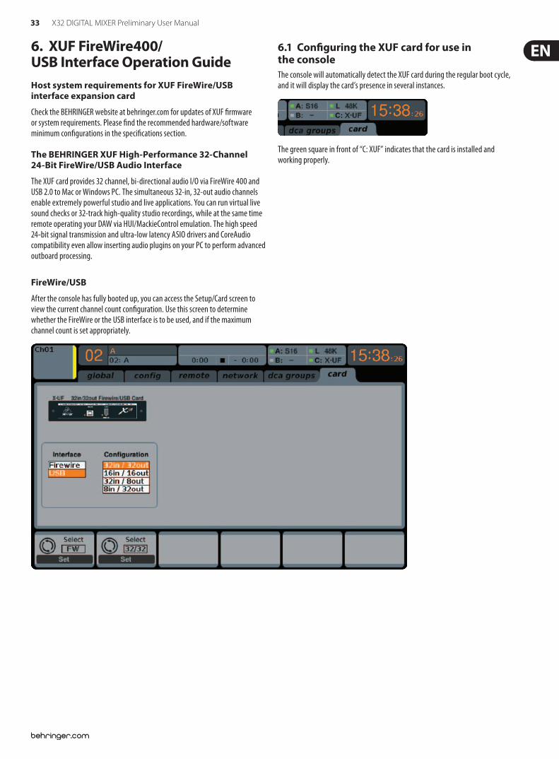
33 X32 DIGITAL MIXER Preliminary User Manual
6. XUF FireWire400/ USB Interface Operation GuideHost system requirements for XUF FireWire/USB interface expansion card
Check the BEHRINGER website at behringer.com for updates of XUF $rmware or system requirements. Please $nd the recommended hardware/software minimum con$gurations in the speci$cations section.
The BEHRINGER XUF High-Performance 32-Channel 24-Bit FireWire/USB Audio Interface
The XUF card provides 32 channel, bi-directional audio I/O via FireWire 400 and USB 2.0 to Mac or Windows PC. The simultaneous 32-in, 32-out audio channels enable extremely powerful studio and live applications. You can run virtual live sound checks or 32-track high-quality studio recordings, while at the same time remote operating your DAW via HUI/MackieControl emulation. The high speed 24-bit signal transmission and ultra-low latency ASIO drivers and CoreAudio compatibility even allow inserting audio plugins on your PC to perform advanced outboard processing.
6.1 Con!guring the XUF card for use in the consoleThe console will automatically detect the XUF card during the regular boot cycle, and it will display the card’s presence in several instances.
The green square in front of “C: XUF” indicates that the card is installed and working properly.
FireWire/USB
After the console has fully booted up, you can access the Setup/Card screen to view the current channel count con$guration. Use this screen to determine whether the FireWire or the USB interface is to be used, and if the maximum channel count is set appropriately.
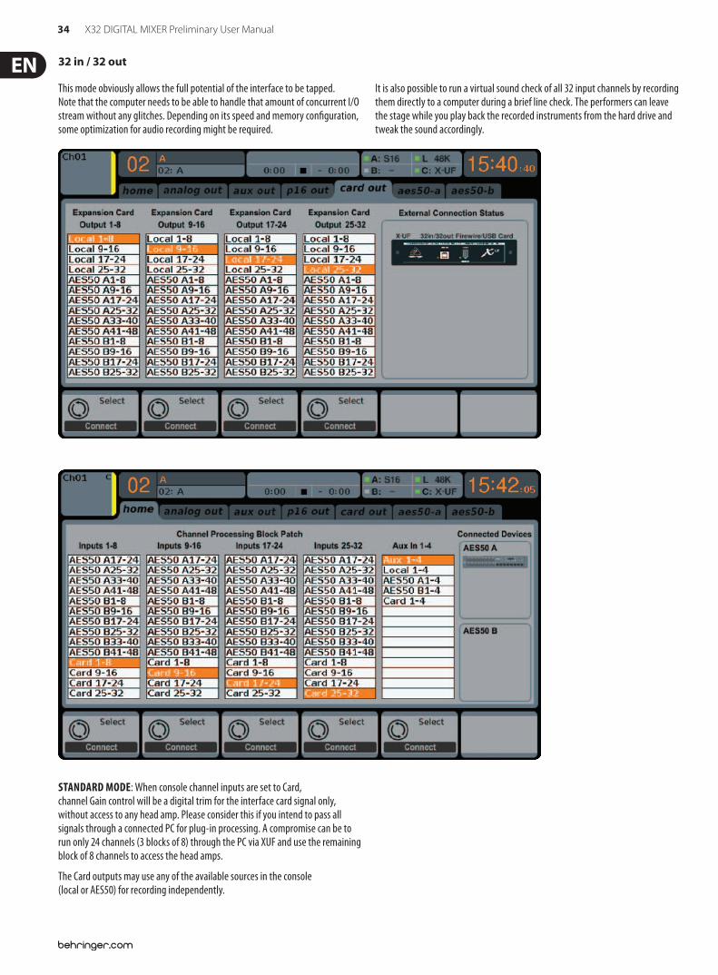
34 X32 DIGITAL MIXER Preliminary User Manual
This mode obviously allows the full potential of the interface to be tapped. Note that the computer needs to be able to handle that amount of concurrent I/O stream without any glitches. Depending on its speed and memory con$guration, some optimization for audio recording might be required.
It is also possible to run a virtual sound check of all 32 input channels by recording them directly to a computer during a brief line check. The performers can leave the stage while you play back the recorded instruments from the hard drive and tweak the sound accordingly.
32 in / 32 out
STANDARD MODE: When console channel inputs are set to Card, channel Gain control will be a digital trim for the interface card signal only, without access to any head amp. Please consider this if you intend to pass all signals through a connected PC for plug-in processing. A compromise can be to run only 24 channels (3 blocks of 8) through the PC via XUF and use the remaining block of 8 channels to access the head amps.
The Card outputs may use any of the available sources in the console (local or AES50) for recording independently.
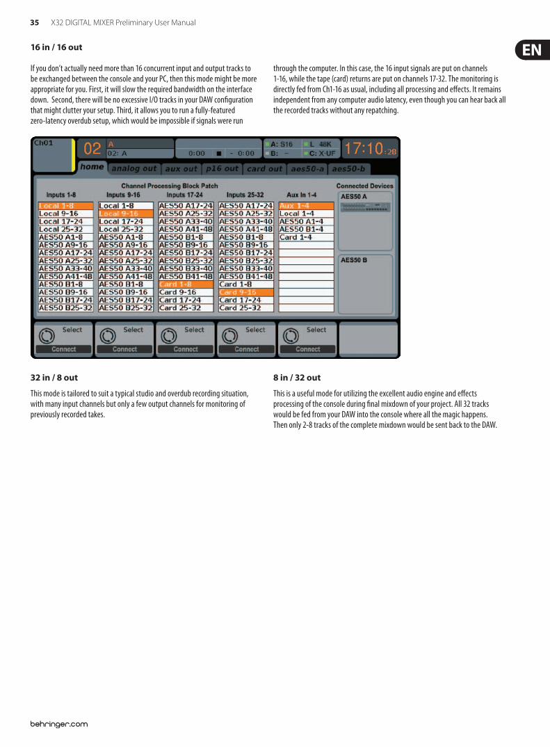
35 X32 DIGITAL MIXER Preliminary User Manual
16 in / 16 out
32 in / 8 out
This mode is tailored to suit a typical studio and overdub recording situation, with many input channels but only a few output channels for monitoring of previously recorded takes.
8 in / 32 out
This is a useful mode for utilizing the excellent audio engine and e!ects processing of the console during $nal mixdown of your project. All 32 tracks would be fed from your DAW into the console where all the magic happens. Then only 2-8 tracks of the complete mixdown would be sent back to the DAW.
If you don’t actually need more than 16 concurrent input and output tracks to be exchanged between the console and your PC, then this mode might be more appropriate for you. First, it will slow the required bandwidth on the interface down. Second, there will be no excessive I/O tracks in your DAW con$guration that might clutter your setup. Third, it allows you to run a fully-featured zero-latency overdub setup, which would be impossible if signals were run
through the computer. In this case, the 16 input signals are put on channels 1-16, while the tape (card) returns are put on channels 17-32. The monitoring is directly fed from Ch1-16 as usual, including all processing and e!ects. It remains independent from any computer audio latency, even though you can hear back all the recorded tracks without any repatching.
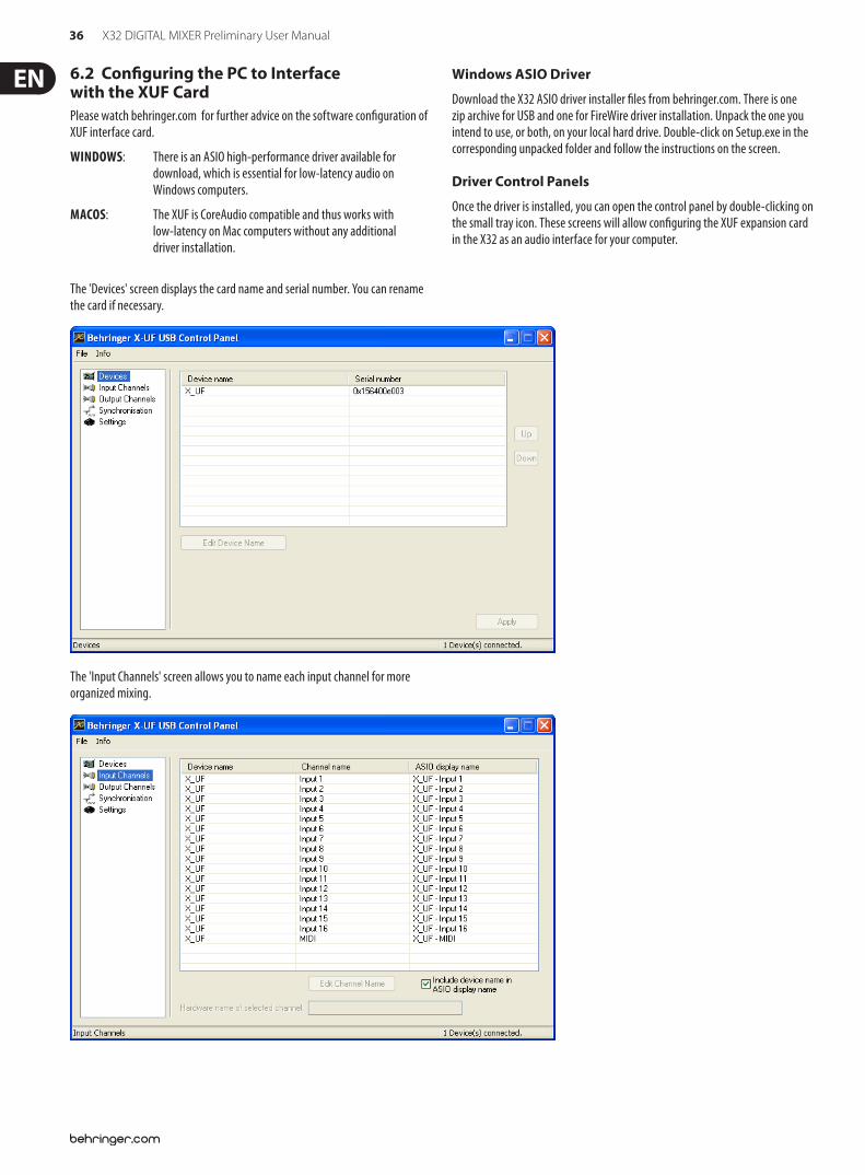
36 X32 DIGITAL MIXER Preliminary User Manual
6.2 Con!guring the PC to Interface with the XUF CardPlease watch behringer.com for further advice on the software con$guration of XUF interface card.
WINDOWS: There is an ASIO high-performance driver available for download, which is essential for low-latency audio on Windows computers.
MACOS: The XUF is CoreAudio compatible and thus works with low-latency on Mac computers without any additional driver installation.
Windows ASIO Driver
Download the X32 ASIO driver installer $les from behringer.com. There is one zip archive for USB and one for FireWire driver installation. Unpack the one you intend to use, or both, on your local hard drive. Double-click on Setup.exe in the corresponding unpacked folder and follow the instructions on the screen.
Driver Control Panels
Once the driver is installed, you can open the control panel by double-clicking on the small tray icon. These screens will allow con$guring the XUF expansion card in the X32 as an audio interface for your computer.
The 'Devices' screen displays the card name and serial number. You can rename the card if necessary.
The 'Input Channels' screen allows you to name each input channel for more organized mixing.
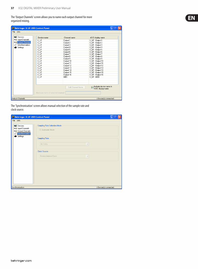
37 X32 DIGITAL MIXER Preliminary User Manual
The 'Output Channels' screen allows you to name each output channel for more organized mixing.
The 'Synchronisation' screen allows manual selection of the sample rate and clock source.
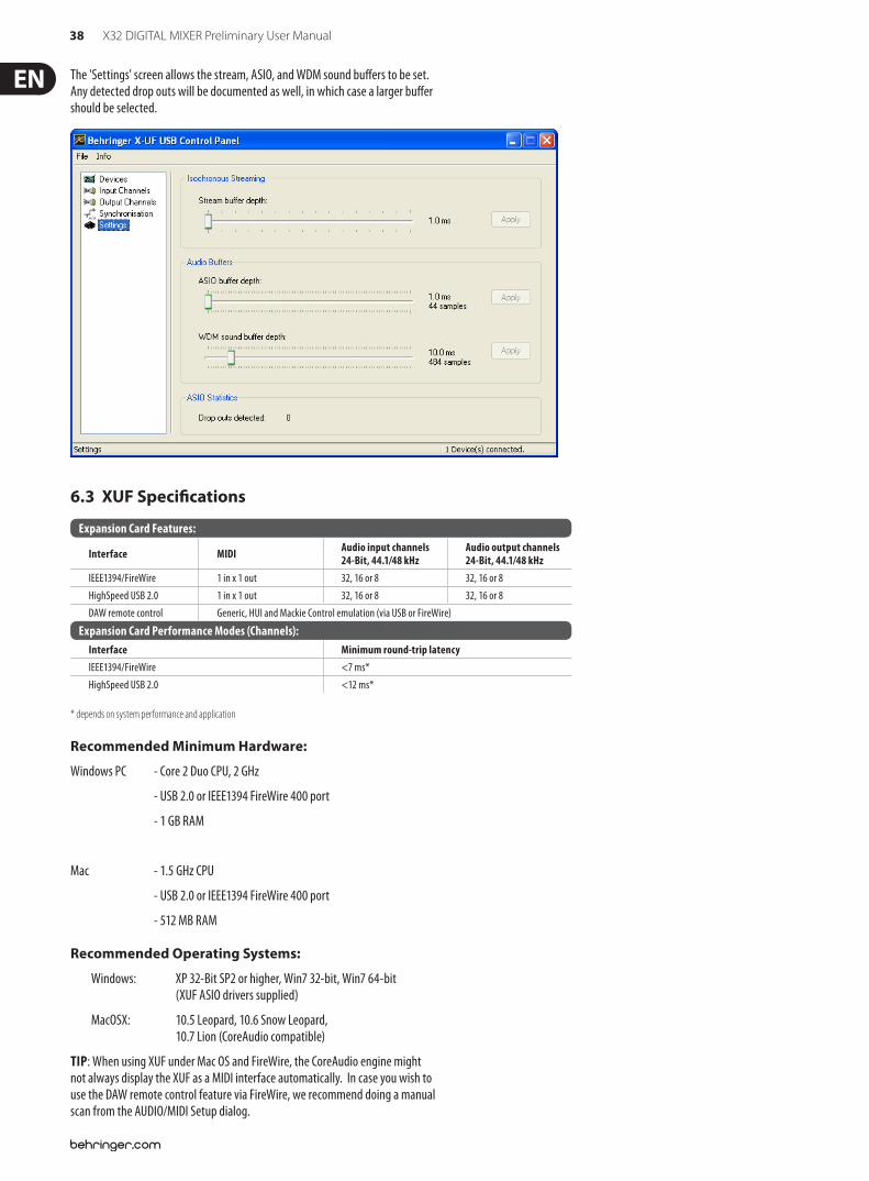
38 X32 DIGITAL MIXER Preliminary User Manual
The 'Settings' screen allows the stream, ASIO, and WDM sound bu!ers to be set. Any detected drop outs will be documented as well, in which case a larger bu!er should be selected.
6.3 XUF Speci!cations
* depends on system performance and application
Expansion Card Features:
Interface MIDI Audio input channels 24-Bit, 44.1/48 kHz
Audio output channels 24-Bit, 44.1/48 kHz
IEEE1394/FireWire 1 in x 1 out 32, 16 or 8 32, 16 or 8HighSpeed USB 2.0 1 in x 1 out 32, 16 or 8 32, 16 or 8DAW remote control Generic, HUI and Mackie Control emulation (via USB or FireWire)
Expansion Card Performance Modes (Channels): Interface Minimum round-trip latencyIEEE1394/FireWire <7 ms*HighSpeed USB 2.0 <12 ms*
Recommended Minimum Hardware:
Windows PC - Core 2 Duo CPU, 2 GHz
- USB 2.0 or IEEE1394 FireWire 400 port
- 1 GB RAM
Mac - 1.5 GHz CPU
- USB 2.0 or IEEE1394 FireWire 400 port
- 512 MB RAM
Recommended Operating Systems:
Windows: XP 32-Bit SP2 or higher, Win7 32-bit, Win7 64-bit (XUF ASIO drivers supplied)
MacOSX: 10.5 Leopard, 10.6 Snow Leopard, 10.7 Lion (CoreAudio compatible)
TIP: When using XUF under Mac OS and FireWire, the CoreAudio engine might not always display the XUF as a MIDI interface automatically. In case you wish to use the DAW remote control feature via FireWire, we recommend doing a manual scan from the AUDIO/MIDI Setup dialog.
39 X32 DIGITAL MIXER Preliminary User Manual
7. X32 Main Display7.1 Overview
7.1.1 Display and Navigation Controls
The controls in this section are used in conjunction with the color screen, in order to navigate and control the graphical elements it contains.
By including dedicated rotary controllers that correspond to adjacent controls on the screen, as well as including cursor buttons, the user can quickly navigate and control all of the color screen’s elements.
Color Screen: This color screen contains various displays that give visual feedback for the operation of the console, and also allow the user to make various adjustments not provided for by the dedicated hardware controls.
Rotary Encoders: These six rotary encoders are used to adjust various color screen elements located directly above them. Each of the six rotary encoders can be pushed inward to activate a button press function. This function is useful when controlling color screen elements that have a dual “on/o!” type state that is best controlled by a button, as opposed to a variable state that is best adjusted by a rotary control.
Screen selection buttons: These 8 illuminated buttons allow the user to immediately navigate to any of 8 master screens that address di!erent sections of the console. The 8 sections that can be navigated to with these buttons are:
1. Home
2. Meters
3. Routing
4. Setup
5. Library
6. E!ects
7. Mute Group
8. Utility
Page Select Buttons: These two buttons allow for left-right navigation among the di!erent “pages” contained within a screen set. A graphical tab display shows which page you are currently on.
Layer Up/Down Buttons: On some screens, there are more parameters present than can be adjusted by the 6 encoders underneath. In these cases, use the layer up/down buttons to navigate through any additional layers contained on the screen page.
L/R Meter: This dual 24-segment meter displays the audio signal level output from the main bus of the console.
M/C SOLO Meter: This dual 24-segment meter displays the audio signal level output from the mono bus of the console. When one or more channels are currently soloed, the meter switches to displaying the level of the currently soloed signal(s).
7.1.2 Console Screens
The color screen of the X32 o!ers a wealth of visual feedback and hands on control for the console. Whereas the dedicated top panel controls o!er immediate hands-on adjustments for the most important operations of a channel, the color screens o!er similarly immediate visual feedback for a selected channel, as well as more global areas of the console.
The screens are divided into three main areas:
1. Global Screen Elements
2. Main Display
3. Rotary Encoder Elements
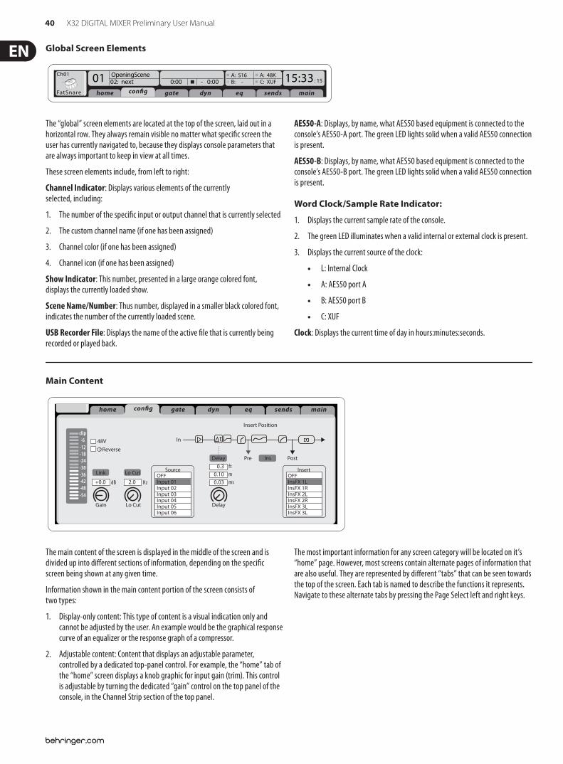
40 X32 DIGITAL MIXER Preliminary User Manual
Main Content
Link Lo Cut
01:01 0:00 - 0:00 B: - C: XUF : 3714:11
-6-12-18-24-30-36-42-48-54
clip
home gate dyn eq sends maincon!g
Gain
Gain
48V In
Pre PostInsDelay
Lo Cut
Lo Cut
Source Ins Pos InsertDelay
Delay
dB+0.0 Hz2.0
Reverse
t
ftmms
0.30.100.03
SourceOFFInput 01Input 02Input 03Input 04Input 05Input 06
InsertOFFInsFX 1LInsFX 1RInsFX 2LInsFX 2RInsFX 3LInsFX 3L
Insert Position
The main content of the screen is displayed in the middle of the screen and is divided up into di!erent sections of information, depending on the speci$c screen being shown at any given time.
Information shown in the main content portion of the screen consists of two types:
1. Display-only content: This type of content is a visual indication only and cannot be adjusted by the user. An example would be the graphical response curve of an equalizer or the response graph of a compressor.
2. Adjustable content: Content that displays an adjustable parameter, controlled by a dedicated top-panel control. For example, the “home” tab of the “home” screen displays a knob graphic for input gain (trim). This control is adjustable by turning the dedicated “gain” control on the top panel of the console, in the Channel Strip section of the top panel.
The most important information for any screen category will be located on it’s “home” page. However, most screens contain alternate pages of information that are also useful. They are represented by di!erent “tabs” that can be seen towards the top of the screen. Each tab is named to describe the functions it represents. Navigate to these alternate tabs by pressing the Page Select left and right keys.
Global Screen Elements
Ch01
FatSnare
OpeningScene02: next 0:00 - 0:00
A: S16 A: 48KB: - C: XUF : 1501 15:33
home con!g gate dyn eq sends main
The “global” screen elements are located at the top of the screen, laid out in a horizontal row. They always remain visible no matter what speci$c screen the user has currently navigated to, because they displays console parameters that are always important to keep in view at all times.
These screen elements include, from left to right:
Channel Indicator: Displays various elements of the currently selected, including:
1. The number of the speci$c input or output channel that is currently selected
2. The custom channel name (if one has been assigned)
3. Channel color (if one has been assigned)
4. Channel icon (if one has been assigned)
Show Indicator: This number, presented in a large orange colored font, displays the currently loaded show.
Scene Name/Number: Thus number, displayed in a smaller black colored font, indicates the number of the currently loaded scene.
USB Recorder File: Displays the name of the active $le that is currently being recorded or played back.
AES50-A: Displays, by name, what AES50 based equipment is connected to the console’s AES50-A port. The green LED lights solid when a valid AES50 connection is present.
AES50-B: Displays, by name, what AES50 based equipment is connected to the console’s AES50-B port. The green LED lights solid when a valid AES50 connection is present.
Word Clock/Sample Rate Indicator:
1. Displays the current sample rate of the console.
2. The green LED illuminates when a valid internal or external clock is present.
3. Displays the current source of the clock:
L: Internal Clock
A: AES50 port A
B: AES50 port B
C: XUF
Clock: Displays the current time of day in hours:minutes:seconds.
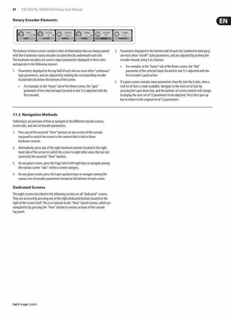
41 X32 DIGITAL MIXER Preliminary User Manual
7.1.3 Navigation Methods
Following is an overview of how to navigate to the di!erent console screens, screen tabs, and sets of encoder parameters.
1. Press any of the assorted “View” buttons on any section of the console top panel to switch the screen to the content that is tied to those hardware controls.
2. Alternatively, press any of the eight hardware buttons located to the right-hand side of the screen to switch the screen to eight other areas that are not covered by the assorted “View” buttons.
3. On any given screen, press the Page Select left/right keys to navigate among the various screen “tabs” within a screen category.
4. On any given screen, press the Layer up/down keys to navigate among the various sets of encoder parameters located at the bottom of each screen.
Dedicated Screens
The eight screens described in the following section are all “dedicated” screens. They are accessed by pressing one of the eight dedicated buttons located to the right of the screen itself. This is in contrast to the “View” based screens, which are navigated to by pressing the “View” button in various sections of the console top panel.
Rotary Encoder Elements:
GaindB+0.00
Link
Lo CutHz20
Lo CutInput
Select
SourcePRE
Insert
Ins PosInsF
Connect
Insertms0.3
Delay
Delay
The bottom of most screens contain 6 slots of information that are always paired with the 6 hardware rotary encoders located directly underneath each slot. The hardware encoders are used to adjust parameters displayed in these slots, and operate in the following manner:
1. Parameters displayed in the top half of each slot are most often “continuous” type parameters, and are adjusted by rotating the corresponding encoder located directly below the bottom of the screen.
For example, in the “home” tab of the Home screen, the “gain” parameter of the selected input (located in slot 1) is adjusted with the $rst encoder.
2. Parameters displayed in the bottom half of each slot (outlined in dark grey) are most often “on/o!” style parameters, and are adjusted by pushing the encoder inward, using it as a button.
For example, in the “home” tab of the Home screen, the “link” parameter of the selected input (located in slot 1) is adjusted with the $rst encoder’s push action.
3. If a given screen contains more parameters than $ts into the 6 slots, then a 2nd set of slots is made available. Navigate to the next set of slots by pressing the Layer down key, and the bottom-of-screen content will change to display the next set of 12 parameters to be adjusted. Press the Layer up key to return to the original set of 12 parameters.
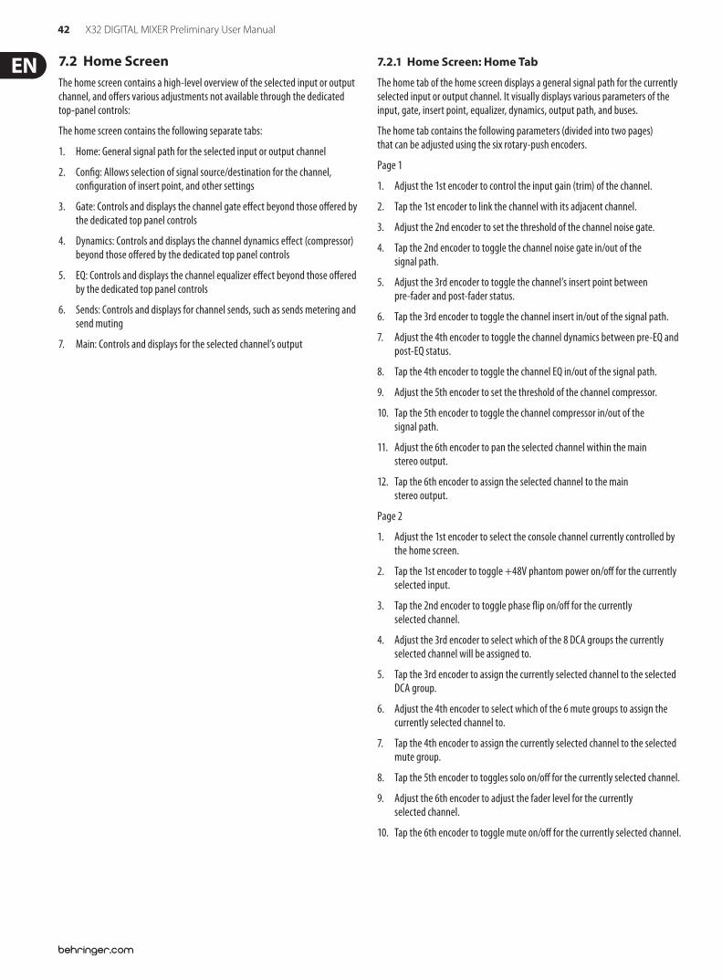
42 X32 DIGITAL MIXER Preliminary User Manual
7.2 Home ScreenThe home screen contains a high-level overview of the selected input or output channel, and o!ers various adjustments not available through the dedicated top-panel controls:
The home screen contains the following separate tabs:
1. Home: General signal path for the selected input or output channel
2. Con$g: Allows selection of signal source/destination for the channel, con$guration of insert point, and other settings
3. Gate: Controls and displays the channel gate e!ect beyond those o!ered by the dedicated top panel controls
4. Dynamics: Controls and displays the channel dynamics e!ect (compressor) beyond those o!ered by the dedicated top panel controls
5. EQ: Controls and displays the channel equalizer e!ect beyond those o!ered by the dedicated top panel controls
6. Sends: Controls and displays for channel sends, such as sends metering and send muting
7. Main: Controls and displays for the selected channel’s output
7.2.1 Home Screen: Home Tab
The home tab of the home screen displays a general signal path for the currently selected input or output channel. It visually displays various parameters of the input, gate, insert point, equalizer, dynamics, output path, and buses.
The home tab contains the following parameters (divided into two pages) that can be adjusted using the six rotary-push encoders.
Page 1
1. Adjust the 1st encoder to control the input gain (trim) of the channel.
2. Tap the 1st encoder to link the channel with its adjacent channel.
3. Adjust the 2nd encoder to set the threshold of the channel noise gate.
4. Tap the 2nd encoder to toggle the channel noise gate in/out of the signal path.
5. Adjust the 3rd encoder to toggle the channel’s insert point between pre-fader and post-fader status.
6. Tap the 3rd encoder to toggle the channel insert in/out of the signal path.
7. Adjust the 4th encoder to toggle the channel dynamics between pre-EQ and post-EQ status.
8. Tap the 4th encoder to toggle the channel EQ in/out of the signal path.
9. Adjust the 5th encoder to set the threshold of the channel compressor.
10. Tap the 5th encoder to toggle the channel compressor in/out of the signal path.
11. Adjust the 6th encoder to pan the selected channel within the main stereo output.
12. Tap the 6th encoder to assign the selected channel to the main stereo output.
Page 2
1. Adjust the 1st encoder to select the console channel currently controlled by the home screen.
2. Tap the 1st encoder to toggle +48V phantom power on/o! for the currently selected input.
3. Tap the 2nd encoder to toggle phase "ip on/o! for the currently selected channel.
4. Adjust the 3rd encoder to select which of the 8 DCA groups the currently selected channel will be assigned to.
5. Tap the 3rd encoder to assign the currently selected channel to the selected DCA group.
6. Adjust the 4th encoder to select which of the 6 mute groups to assign the currently selected channel to.
7. Tap the 4th encoder to assign the currently selected channel to the selected mute group.
8. Tap the 5th encoder to toggles solo on/o! for the currently selected channel.
9. Adjust the 6th encoder to adjust the fader level for the currently selected channel.
10. Tap the 6th encoder to toggle mute on/o! for the currently selected channel.
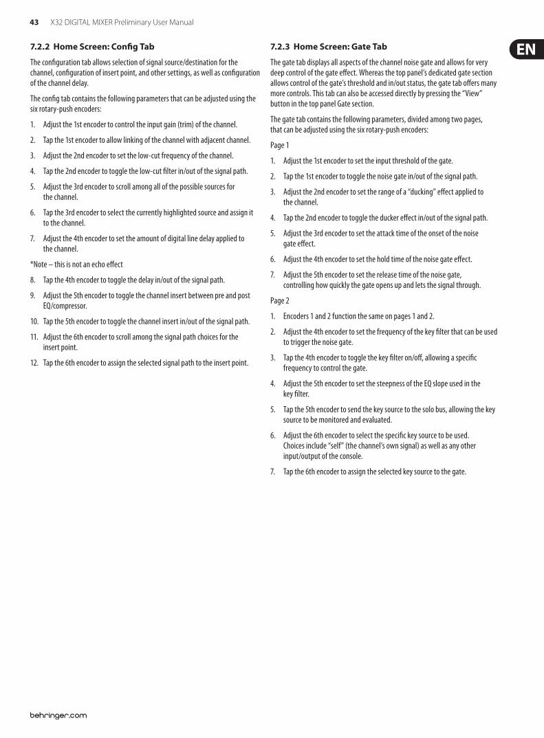
43 X32 DIGITAL MIXER Preliminary User Manual
7.2.2 Home Screen: Con!g Tab
The con$guration tab allows selection of signal source/destination for the channel, con$guration of insert point, and other settings, as well as con$guration of the channel delay.
The con$g tab contains the following parameters that can be adjusted using the six rotary-push encoders:
1. Adjust the 1st encoder to control the input gain (trim) of the channel.
2. Tap the 1st encoder to allow linking of the channel with adjacent channel.
3. Adjust the 2nd encoder to set the low-cut frequency of the channel.
4. Tap the 2nd encoder to toggle the low-cut $lter in/out of the signal path.
5. Adjust the 3rd encoder to scroll among all of the possible sources for the channel.
6. Tap the 3rd encoder to select the currently highlighted source and assign it to the channel.
7. Adjust the 4th encoder to set the amount of digital line delay applied to the channel.
*Note – this is not an echo e!ect
8. Tap the 4th encoder to toggle the delay in/out of the signal path.
9. Adjust the 5th encoder to toggle the channel insert between pre and post EQ/compressor.
10. Tap the 5th encoder to toggle the channel insert in/out of the signal path.
11. Adjust the 6th encoder to scroll among the signal path choices for the insert point.
12. Tap the 6th encoder to assign the selected signal path to the insert point.
7.2.3 Home Screen: Gate Tab
The gate tab displays all aspects of the channel noise gate and allows for very deep control of the gate e!ect. Whereas the top panel’s dedicated gate section allows control of the gate’s threshold and in/out status, the gate tab o!ers many more controls. This tab can also be accessed directly by pressing the “View” button in the top panel Gate section.
The gate tab contains the following parameters, divided among two pages, that can be adjusted using the six rotary-push encoders:
Page 1
1. Adjust the 1st encoder to set the input threshold of the gate.
2. Tap the 1st encoder to toggle the noise gate in/out of the signal path.
3. Adjust the 2nd encoder to set the range of a “ducking” e!ect applied to the channel.
4. Tap the 2nd encoder to toggle the ducker e!ect in/out of the signal path.
5. Adjust the 3rd encoder to set the attack time of the onset of the noise gate e!ect.
6. Adjust the 4th encoder to set the hold time of the noise gate e!ect.
7. Adjust the 5th encoder to set the release time of the noise gate, controlling how quickly the gate opens up and lets the signal through.
Page 2
1. Encoders 1 and 2 function the same on pages 1 and 2.
2. Adjust the 4th encoder to set the frequency of the key $lter that can be used to trigger the noise gate.
3. Tap the 4th encoder to toggle the key $lter on/o!, allowing a speci$c frequency to control the gate.
4. Adjust the 5th encoder to set the steepness of the EQ slope used in the key $lter.
5. Tap the 5th encoder to send the key source to the solo bus, allowing the key source to be monitored and evaluated.
6. Adjust the 6th encoder to select the speci$c key source to be used. Choices include “self” (the channel’s own signal) as well as any other input/output of the console.
7. Tap the 6th encoder to assign the selected key source to the gate.
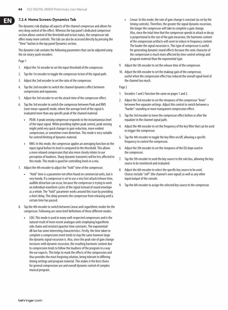
44 X32 DIGITAL MIXER Preliminary User Manual
7.2.4 Home Screen: Dynamics Tab
The dynamics tab displays all aspects of the channel compressor and allows for very deep control of the e!ect. Whereas the top panel’s dedicated compressor section allows control of the threshold and in/out status, the compressor tab o!ers many more controls. This tab can also be accessed directly by pressing the “View” button in the top panel Dynamics section.
The dynamics tab contains the following parameters that can be adjusted using the six rotary-push encoders:
Page 1
1. Adjust the 1st encoder to set the input threshold of the compressor.
2. Tap the 1st encoder to toggle the compressor in/out of the signal path.
3. Adjust the 2nd encoder to set the ratio of the compressor.
4. Tap the 2nd encoder to switch the channel dynamics e!ect between compression and expansion.
5. Adjust the 3rd encoder to set the attack time of the compressor e!ect.
6. Tap the 3rd encoder to switch the compressor between Peak and RMS (root-mean-squared) mode, where the average level of the signal is evaluated more than any speci$c peak of the channel material.
PEAK: A peak sensing compressor responds to the instantaneous level of the input signal. While providing tighter peak control, peak sensing might yield very quick changes in gain reduction, more evident compression, or sometimes even distortion. This mode is very suitable for control/limiting of dynamic material.
RMS: In this mode, the compressor applies an averaging function on the input signal before its level is compared to the threshold. This allows a more relaxed compression that also more closely relates to our perception of loudness. Sharp dynamic transients will be less a!ected in this mode. This mode is good for controlling levels in a mix.
7. Adjust the 4th encoder to adjust the “hold” time of the compressor.
“Hold” time is a parameter not often found on commercial units, but is very handy. If a compressor is set to use a very fast attack/release time, audible distortion can occur, because the compressor is trying to work on individual waveform cycles of the signal instead of sound envelope as a whole. The “hold” parameter works around this issue by providing a short delay. This delay prevents the compressor from releasing until a certain time has passed.
8. Tap the 4th encoder to switch between Linear and Logarithmic modes for the compressor. Following are some brief de$nitions of these di!erent modes:
LOG: This mode is used in many well-respected compressors and is the natural result of more recent analogue units employing logarithmic side chains and resistor/capacitor time constants. The exponential/dB law has some interesting characteristics. Firstly, the time taken to complete a compression event tends to stay the same however large the dynamic signal excursion is. Also, since the peak rate of gain change increases with dynamic excursion, the resulting harmonic content due to compression tends to follow the loudness of the program in a way the ear expects. This helps to mask the e!ects of the compression and thus provides the most forgiving solution, being tolerant to di!ering timing settings and program material. This makes it the best choice for general compression use and overall dynamic control of complex musical program.
Linear: In this mode, the rate of gain change is constant (as set by the timing controls). Therefore, the greater the signal dynamic excursion, the longer the compressor will take to complete a gain change. Also, since the total time that the compressor spends in attack or decay is proportional to the size of the gain excursion, the harmonic content of the compression artifacts will seem to reduce in frequency content. The louder the signal excursion is. This type of compressor is useful for generating dynamic sound e!ects because the sonic character of the compression is much more a!ected by time control settings and program material than the exponential type.
9. Adjust the 5th encoder to set the release time of the compressor.
10. Adjust the 6th encoder to set the makeup gain of the compressor, useful when the compression e!ect has reduced the overall signal level of the channel too much.
Page 2
1. Encoders 1 and 2 function the same on pages 1 and 2.
2. Adjust the 3rd encoder to set the steepness of the compressor “knee” between $ve separate settings. Adjust this control to switch between a “harder” sounding or more transparent compression e!ect.
3. Tap the 3rd encoder to move the compressor e!ect before or after the equalizer in the channel signal path.
4. Adjust the 4th encoder to set the frequency of the key $lter that can be used to trigger the compressor.
5. Tap the 4th encoder to toggle the key $lter on/o!, allowing a speci$c frequency to control the compressor.
6. Adjust the 5th encoder to set the steepness of the EQ slope used in the compressor.
7. Tap the 5th encoder to send the key source to the solo bus, allowing the key source to be monitored and evaluated.
8. Adjust the 6th encoder to select the speci$c key source to be used. Choices include “self” (the channel’s own signal) as well as any other input/output of the console.
9. Tap the 6th encoder to assign the selected key source to the compressor.
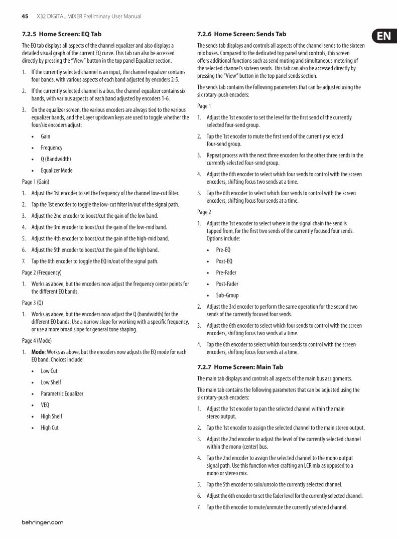
45 X32 DIGITAL MIXER Preliminary User Manual
7.2.5 Home Screen: EQ Tab
The EQ tab displays all aspects of the channel equalizer and also displays a detailed visual graph of the current EQ curve. This tab can also be accessed directly by pressing the “View” button in the top panel Equalizer section.
1. If the currently selected channel is an input, the channel equalizer contains four bands, with various aspects of each band adjusted by encoders 2-5.
2. If the currently selected channel is a bus, the channel equalizer contains six bands, with various aspects of each band adjusted by encoders 1-6.
3. On the equalizer screen, the various encoders are always tied to the various equalizer bands, and the Layer up/down keys are used to toggle whether the four/six encoders adjust:
Gain
Frequency
Q (Bandwidth)
Equalizer Mode
Page 1 (Gain)
1. Adjust the 1st encoder to set the frequency of the channel low-cut $lter.
2. Tap the 1st encoder to toggle the low-cut $lter in/out of the signal path.
3. Adjust the 2nd encoder to boost/cut the gain of the low band.
4. Adjust the 3rd encoder to boost/cut the gain of the low-mid band.
5. Adjust the 4th encoder to boost/cut the gain of the high-mid band.
6. Adjust the 5th encoder to boost/cut the gain of the high band.
7. Tap the 6th encoder to toggle the EQ in/out of the signal path.
Page 2 (Frequency)
1. Works as above, but the encoders now adjust the frequency center points for the di!erent EQ bands.
Page 3 (Q)
1. Works as above, but the encoders now adjust the Q (bandwidth) for the di!erent EQ bands. Use a narrow slope for working with a speci$c frequency, or use a more broad slope for general tone shaping.
Page 4 (Mode)
1. Mode: Works as above, but the encoders now adjusts the EQ mode for each EQ band. Choices include:
Low Cut
Low Shelf
Parametric Equalizer
VEQ
High Shelf
High Cut
7.2.6 Home Screen: Sends Tab
The sends tab displays and controls all aspects of the channel sends to the sixteen mix buses. Compared to the dedicated top panel send controls, this screen o!ers additional functions such as send muting and simultaneous metering of the selected channel’s sixteen sends. This tab can also be accessed directly by pressing the “View” button in the top panel sends section.
The sends tab contains the following parameters that can be adjusted using the six rotary-push encoders:
Page 1
1. Adjust the 1st encoder to set the level for the $rst send of the currently selected four-send group.
2. Tap the 1st encoder to mute the $rst send of the currently selected four-send group.
3. Repeat process with the next three encoders for the other three sends in the currently selected four-send group.
4. Adjust the 6th encoder to select which four sends to control with the screen encoders, shifting focus two sends at a time.
5. Tap the 6th encoder to select which four sends to control with the screen encoders, shifting focus four sends at a time.
Page 2
1. Adjust the 1st encoder to select where in the signal chain the send is tapped from, for the $rst two sends of the currently focused four sends. Options include:
Pre-EQ
Post-EQ
Pre-Fader
Post-Fader
Sub-Group
2. Adjust the 3rd encoder to perform the same operation for the second two sends of the currently focused four sends.
3. Adjust the 6th encoder to select which four sends to control with the screen encoders, shifting focus two sends at a time.
4. Tap the 6th encoder to select which four sends to control with the screen encoders, shifting focus four sends at a time.
7.2.7 Home Screen: Main Tab
The main tab displays and controls all aspects of the main bus assignments.
The main tab contains the following parameters that can be adjusted using the six rotary-push encoders:
1. Adjust the 1st encoder to pan the selected channel within the main stereo output.
2. Tap the 1st encoder to assign the selected channel to the main stereo output.
3. Adjust the 2nd encoder to adjust the level of the currently selected channel within the mono (center) bus.
4. Tap the 2nd encoder to assign the selected channel to the mono output signal path. Use this function when crafting an LCR mix as opposed to a mono or stereo mix.
5. Tap the 5th encoder to solo/unsolo the currently selected channel.
6. Adjust the 6th encoder to set the fader level for the currently selected channel.
7. Tap the 6th encoder to mute/unmute the currently selected channel.
46 X32 DIGITAL MIXER Preliminary User Manual
7.3 Meters ScreenThe meters screen displays di!erent groups of level meters for various signal paths of the console, and is useful for quickly ascertaining if any channels need level adjustment. Since there are no parameters to adjust for the metering displays, none of the metering screens contain any “bottom-of-screen” controls that would normally be adjusted by the 6 rotary encoders.
The meter screen contains the following separate screen tabs, each containing level meters for the following signal paths:
1. Channel:
Level meters and fader levels for the 32 input channels
Gate response meters for the 16 input channels
Gain reduction meters for the 16 input channels
2. Mix Bus:
Level meters, fader levels, and gain reduction meters for the 16 bus masters
Level meters, fader levels, and gain reduction meters for the 6 matrix outputs
Level meters, fader levels, and gain reduction meters for the stereo main bus and the mono bus
3. Aux/FX:
Level meters for the 6 auxiliary sends
Level meters and fader levels for the 8 auxiliary returns
Level meters and fader levels for the 4 stereo e!ects returns
4. In/Out:
The 32 input channels
The 8 auxiliary returns
The 6 auxiliary sends
The two rear panel digital outputs
Monitor outputs
The 16 rear panel analog outputs
The P16 Ultranet outputs
47 X32 DIGITAL MIXER Preliminary User Manual
7.4 Routing ScreenThe routing screen is where all signal patching is done, allowing you to route internal signal paths to and from the physical input/output connectors located on the console’s rear panel.
The routing screen contains the following separate tabs:
1. Home: Allows patching of physical inputs to the 32 input channels and Aux inputs of the console.
2. Analog Out: Allows patching of internal signal paths to the console’s 16 rear-panel XLR outputs.
3. Aux Out: Allows patching of internal signal paths to the console’s 6 rear-panel ¼"/RCA auxiliary outputs.
4. P16 Out: Allows patching of internal signal paths to the 16 outputs of the console’s 16-channel P16 Ultranet output.
5. Card Out: Allows patching of internal signal paths to the 32 outputs of the XUF card.
6. AES50-A: Allows patching of internal signal paths to the 48 outputs of the rear panel AES50-A output.
7. AES50-B: Allows patching of internal signal paths to the 48 outputs of the rear panel AES50-B output.
None of the routing screen's tabs contains a secondary level of encoder functions. When routing audio, the Layer up/down keys do not need to be used.
7.4.1 Routing Screen: Home Tab
The routing screen’s home tab allows the user to patch the console’s physical rear-panel inputs to the 32 input channels and Aux inputs of the console.
As a default, the console maps the console’s 32 rear-panel analog inputs to their the respective 32 channel inputs that are accessed on input fader layers one and two, and maps the rear panel line-level (auxiliary) inputs to the third input fader layer.
However, the home tab of the routing screen can be used to change this default assignment and “crosspatch” di!erent physical inputs to di!erent channel inputs, in banks of 8 channels at a time. This allows the user to create a custom layout of channel inputs that di!ers from the order that the sources are plugged into the rear panel, and is easier than physically re-patching physical audio cables.
To assign various inputs to the console’s input channels, perform the following steps:
1. Adjust the $rst rotary encoder to select which 8-channel audio input source feeds input channels 1-8 of the console. As the encoder is rotated, the currently selected input will be highlighted in the vertical list of choices.
2. When the desired 8-channel source is selected, push the 1st encoder to “connect” the currently selected 8-channel source. The selected source now feeds input channels 1-8 of the console.
3. Input choices that can be assigned include:
Local 1-8
Local 9-16
Local 17-24
Local 25-32
AES50-A 1-8
AES50-A 9-16
AES50-A 17-24
AES50-A 25-32
AES50-A 33-40
AES50-A 41-48
AES50-B 1-8
AES50-B 9-16
AES50-B 17-24
AES50-B 25-32
AES50-B 33-40
AES50-B 41-48
Card 1-8
Card 9-16
Card 17-24
Card 25-32
4. To assign an 8-channel source for the other input channels of the console (9-16, 17-24, 25-32), simply repeat the process above, using the other four rotary encoders on the same screen.
5. Choices for Aux In 1-4 include:
Aux 1-4
Local 1-4
AES50-A 1-4
AES50-B 1-4
Card 1-4
48 X32 DIGITAL MIXER Preliminary User Manual
7.4.2 Routing Screen: Analog Out Tab
The routing screen’s analog out tab allows the user to patch the console’s various internal signal paths to the 16 analog XLR outputs that are located on the console rear panel.
The X32 console allows for many di!erent kinds of output signal paths, and this screen is where these output paths are assigned to an actual physical rear panel output so that the signal path can be patched to their eventual destination (such as the front-of-house PA speakers or a powered stage monitor).
To assign the various output paths to the rear panel XLR outputs, perform the following steps:
1. Adjust the 1st encoder to select which of the 16 rear panel analog outs you wish to assign an output signal path to.
2. Adjust the 3rd encoder to select an output path “category”. These categories include:
O!
Main (LRC) Mix
Mix Bus Outputs
Matrix Outputs
Direct Outs
Monitor
3. Adjust the 4th encoder to select a speci$c output path, including:
O!
Main L
Main R
Main C/M
Any of the 16 Mix Outputs
Any of the 6 matrix outputs
Any of the 32 direct outputs
Any of the 8 Auxiliary Outputs
Any of the FX Direct Outputs
Monitor L
Monitor R
Talkback
4. Tap the 4th encoder to assign the selected output path, completing the process.
5. Adjust the 5th encoder to select the signal tap point for the output assignment. This determines where in the audio signal path the source is “tapped” as it is sent to the physical rear panel output. The available signal tap points include:
Input
Pre-EQ
Pre-Fader
Post-Fader
6. Tap the 5th encoder to assign the selected signal tap point.
7. Adjust the 6th encoder to adjust the amount of digital line delay applied to the output path as it is sent to the rear-panel physical output. As the amount of delay is adjusted, the current delay time is displayed in three di!erent units of measurement: Feet, Meters, and Milliseconds.
8. Tap the 6th encoder to toggle delay on/o!. The “delay” label illuminates when the delay is inserted into the signal path.
TIP: Applying a delay to an output signal is typically done when the console is used in a “multi-zone” P.A. speaker setup, where some PA speakers are located near the stage and a second set of speakers are located further back within the audience. By applying an appropriate amount of delay only to the speakers located near the stage, the audience hears the audio from the closer/further speakers at the same time, insuring maximum time-alignment and sound quality. The console assumes an operating temperature of 20°C/68°F when calculating the delay times.
7.4.3 Routing Screen: Aux Out Tab
The route screen’s aux out tab allows the user to patch an internal signal path (such as a mix output used as an e!ects send) to the 6 separate ¼"/RCA auxiliary outputs.
Since these six outputs can have a wide variety of signal paths assigned to them, they can be used for a wide variety of tasks, such as:
1. Feeding an external e!ects processor when the internal e!ects are insu&cient
2. Patching a speci$c console signal path into an outboard recorder
3. Feeding the analog or digital audio inputs of a nearby video recorder
To make an assignment as described above, perform the following steps:
4. Adjust the 1st encoder to select which auxiliary outputs to assign a source for. Choices include:
Aux Out 1
Aux Out 2
Aux Out 3
Aux Out 4
Aux Out 5
Aux Out 6
AES/EBU (Digital) Out L
AES/EBU (Digital) Out R
49 X32 DIGITAL MIXER Preliminary User Manual
5. Adjust the 3rd encoder to select for coarse range
Insert
Main (LRC)
Mix Bus
Matrix
Direct Out
Monitor
6. Adjust 4th encoder to select speci$c signal path to feed the selected physical output. Choices include:
Insert Point
Main L
Main R
Main C/M
Any of the 16 Mix Outputs
Any of the 6 matrix outputs
Any of the 32 direct outputs
Any of the 8 Auxiliary Outputs
Any of the FX Direct Outputs
Monitor L
Monitor R
Talkback
7. Tap the 4th encoder to assign the selected output path, completing the process.
8. Adjust the 5th encoder to select the signal tap point for the output assignment. Choices include:
Input
Pre-EQ
Pre-Fader
Post-Fader
9. Tap the 5th encoder to complete the signal tap point assignment.
7.4.4 Routing Screen: P16 Tab
The routing screen’s P16 tab allows the user to route various console signal paths to the rear panel P16 Ultranet output. The Ultranet output allows for 16 channels of audio to be sent, in digital form, to various accessories such as a personal monitoring distribution box.
Using the P16 routing screen, the user can con$gure the P16 output to carry not only the main LR mix, but also various audio “stems” of program material sources from a bus send mix, such as a stereo drum mix, stereo keyboards, guitars, bass, vocals, etc. Musicians on stage would then be free to each craft their own personal mix of these musical stems, all delivered from the FOH position to stage over a single Ethernet cable.
To select which audio signals are sent to the P16 bus, perform the following steps:
1. Adjust the 1st encoder to select which of the 16 channels in the P16 bus you wish to select an audio source for.
2. Adjust the 3rd encoder to select a category of audio source to send to the currently selected P16 channel. These categories include:
Insert
Main (LRC)
Mix Bus
Matrix
Direct Out
Monitor
3. Adjust the 4th encoder to select which speci$c signal path to feed to the currently selected P16 output. Choices include:
O!
Main L
Main R
Main C/M
Any of the 16 Mix Outputs
Any of the 6 matrix outputs
Any of the 32 direct outputs
Any of the 8 Auxiliary Outputs
Any of the FX Direct Outputs
Monitor L
Monitor R
Talkback
4. Tap the 4th encoder to assign the selected output path, completing the process.
5. Adjust the 5th encoder to select the signal tap point for the output assignment. This determines where in the audio signal path the source is “tapped” as it is sent to the P16 output. The available signal tap points include:
Input
Pre-EQ
Pre-Fader
Post-Fader
6. Tap the 5th encoder to complete the signal tap point assignment.
50 X32 DIGITAL MIXER Preliminary User Manual
7.4.5 Routing Screen: Card Output Tab:
The routing screen’s card tab allows the user to patch various signal paths to the physical inputs and outputs of the XUF card. The XUF’s signal path provides 32 channels of inputs and 32 channels of outputs. The 32 card inputs can be used as alternate sources for the two input fader layers, switchable in banks of 8.
To assign an output path to the option card, perform the following steps:
1. Adjust the 1st encoder to select which 8-channel output path to send to the $rst 8 outputs of the card. Choices include:
Local 1-8
Local 9-16
Local 17-24
Local 25-32
AES50-A 1-8
AES50-A 9-16
AES50-A 17-24
AES50-A 25-32
AES50-A 33-40
AES50-A 41-48
AES50-B 1-8
AES50-B 9-16
AES50-B 17-24
AES50-B 25-32
AES50-B 33-40
AES50-B 41-48
Card 1-8
Card 9-16
Card 17-24
Card 25-32
Out 1-8
Out 9-16
P16 1-8
P16 9-16
Aux 1-6/Mon
2. Tap the 1st encoder to assign the selected output path, completing the process.
3. Repeat the process with encoders 2-4 to select output paths for the other 24 channels of card outputs.
7.4.6 Routing Screen: AES50-A and AES50-B Tabs:
The routing screen’s AES50-A and AES50-B tabs allow the user to patch various console output paths to the outputs of the dual AES50 connectors. These AES50 connectors can feed other AES50 equipped devices such as a digital stagebox or standalone multi-track recorder.
The console contains two separate AES50 connectors, an “A” connector and a “B” connector. These dual connectors allow for an increased level of "exibility in networking the console with various AES50 based equipment.
Each of the two AES50 screens contains the same following sets of parameters that can be adjusted. To assign various console signal paths to the AES50 connectors, perform the following steps:
1. Adjust the 1st encoder to select an 8-channel signal path that will be sent to the $rst 8 channels of the AES50 connectors output. Choices include:
Local 1-8
Local 9-16
Local 17-24
Local 25-32
AES50-A 1-8
AES50-A 9-16
AES50-A 17-24
AES50-A 25-32
AES50-A 33-40
AES50-A 41-48
AES50-B 1-8
AES50-B 9-16
AES50-B 17-24
AES50-B 25-32
AES50-B 33-40
AES50-B 41-48
Card 1-8
Card 9-16
Card 17-24
Card 25-32
Out 1-8
Out 9-16
P16 1-8
P16 9-16
Aux 1-6/Mon
2. Tap the 1st encoder to connect the currently selected signal path to the AES50 pathway.
3. Repeat the above process for the other $ve sets of 8-channel AES50 outputs.
The AES50-B tab works exactly the same as the AES50-A screen, but instead selects sources sent to the output of the console’s AES50-B connector.
51 X32 DIGITAL MIXER Preliminary User Manual
7.5 Setup ScreenThe setup screen o!ers various controls for global, high-level functions of the console such as display adjustments, sample rates and synchronization, user settings, and network con$guration.
The setup screen contains the following separate tabs:
1. Global: This screen o!ers adjustments for various global preferences of how the console operates.
2. Con$g: This screen o!ers adjustments for sample rates and synchronization, as well as con$guring high-level settings for signal path buses.
3. Remote: This screen o!ers di!erent controls for setting up the console as a control surface for various DAW recording software on a connected computer.
4. Network: This screen o!ers di!erent controls for attaching the console to a standard Ethernet network.
5. DCA Groups: This screen o!ers controls for various aspects of the console’s DCA groups.
6. Card: This screen selects between the USB and FireWire connectors, and also selects the input/output con$guration.
None of the setup screen’s tabs contain a secondary level of encoder functions, so the Layer up/down keys do not need to be used for these screens.
7.5.1 Setup Screen: Global Tab:
The setup screen’s global tab allows the user to adjust various global controls of the console, such as display brightness and contrast, the panning mode used by channels, text languages, and more.
1. To make adjustments in the global screen, perform the following steps:
2. Adjust the $rst encoder to select various console settings for pop-up messages and assorted preferences.
3. Tap the 1st encoder to turn the currently selected setting on/o!.
4. Adjust the 2nd encoder to select settings for linking multiple console channels.
5. Tap the 2nd encoder to turn the currently selected setting on/o!.
6. Adjust the 3rd encoder to set the console’s panning mode, which a!ects how channel panning is performed in the stereo $eld. The two choices are:
LR + Mono: This is the default mode of the console. In this mode, channels can be panned between the left and right mix outputs, as well as assigned to the separate mono mix bus. In this mode, the Center/Mono bus is not a!ected by from the pan control.
LCR enable: In this mode, the signal is panned from Left over Center to Right. This behavior is emulated by the faders on the Main tab, a behavior that is more intuitive than on other consoles. Note that in this mode, the de$nition of “mono” changes since the setup is no longer mono, but rather a setup consisting of Left-Center-Right.
7. Adjust the 4th encoder to set the brightness of the various LED lights of the console, from a range of 1-100.
8. Adjust the 5thth encoder to set the brightness of the color screen (main display), from a range of 1-100.
9. Adjust the 6th encoder to set the brightness of the individual LCD screens (channel display) above each input and output channel, from a range of 1-100.
7.5.2 Setup Screen: Con!g Tab:
The setup screen’s con$g tab allows adjustment of various audio-related settings, such as the console’s base sample rate and use of an internal or external digital clock. It also o!ers choices for high-level global settings for how signal path buses operate.
To adjust the various settings of the con$g tab, perform the following steps:
1. Adjust the 1st encoder to select between Console, Show Data, and Libraries for initialization.
2. Tap the 1st encoder to initialize the console back to its factory state.
An “are you sure” message will appear. Use the left Page Select key to cancel out of the operation, or the right key to con$rm the operation and initialize the console.
3. The console’s current $rmware is displayed in the $rst column of the main color screen.
If/when a $rmware update is available for the console, the user simply needs to download the new $rmware $le to the root level of a USB thumb drive, attach the thumb drive to the console, and then reboot. The console will see the $rmware $le and an update will be done automatically while booting.
4. Adjust the 2nd encoder to select the digital sample rate of the console. Choices include:
48 kHz
44.1 kHz
5. Tap the second encoder to assign the currently selected sample rate.
Tip: Note that the sample rate of the console will be the same sample rate for any audio recorded to the onboard stereo USB recorder, as well as the sample rate output by the AES/EBU connector that may get patched into an outboard recorder. Thus, it is often bene$cial to select a sample rate that is appropriate for the medium that recorded audio will eventually be used on.
If the program material being recorded is audio only, with no video component, then it usually makes sense to set a sample rate of 44.1 kHz. This will ensure that any audio recorded is compatible with the 44.1 kHz sample rate of commercial audio CDs.
If the program material being recorded is audio that is meant to accompany video, then it usually makes sense to set a sample rate of 48 kHz. This will ensure that any audio recorded is compatible with the 48 kHz sample rate of the various audio formats used on a video DVD.
6. Adjust the 3rd encoder to set the word clock synchronization of the console to use its internal digital clock, or slave to an external digital clock. Choices for the clock signal include:
Internal clock
External clock from the AES50-A port
External clock from the AES50-B port
XUF card
52 X32 DIGITAL MIXER Preliminary User Manual
Note that the graphics at the top of the screen will always display a green led when the console has achieved proper “digital lock”, from either its own internal clock or a valid external clock.
7. Tap the 4th encoder to cycle through the di!erent settings for the console’s internal date and time settings.
8. Adjust the 4th encoder to set the value for the currently selected date/time setting.
9. Adjust the 5th encoder to select the console’s “Bus Pre-Con$guration”. This settings allows the mix bus outputs to be con$gured in various combinations of:
Pre-fader, variable output auxiliary sends
Post-Fader, variable output auxiliary sends
Fixed-output sub groups
10. Choices include:
8 pre-fader auxiliary sends, 8 post-fader auxiliary sends, and no sub-groups
8 pre-fader auxiliary sends, 4 post-fader auxiliary sends, and 4 sub-groups
6 pre-fader auxiliary sends, 4 post-fader auxiliary sends, and 6 sub-groups
4 pre-fader auxiliary sends, 4 post-fader auxiliary sends, and 8 sub-groups
10 pre-fader auxiliary sends, 6 post-fader auxiliary sends, and 0 sub-groups
11. Tap the 5th encoder to assign the currently selected con$guration.
As the con$guration is selected, a display on the right-hand side of the color screen changes to show the currently selected con$guration.
7.5.3 Setup Screen: Remote Tab:
The setup screen’s remote tab allows setting up the console as a control surface for various DAW recording software on a connected computer. With its large complement of motorized faders, the console can act as an excellent controller for various DAW software, allowing the user to make level adjustments quickly and easily without using a mouse.
To adjust the various remote settings, perform the following steps:
1. Tap the 1st encoder to enable the console’s top panel Remote button. This switches various console hardware, such as the bus faders, to control computer DAW software instead of the console’s internal audio path.
2. Adjust the 2nd encoder to select the speci$c control surface protocol used, in conjunction with the target DAW software. Choices include:
Mackie Control: Use this protocol to control any DAW software that is compatible with a Mackie Control hardware control surface.
HUI: Use this protocol to control any D.A.W. software that is compatible with a HUI hardware control surface, such as Pro Tools.
3. Tap the 2nd encoder to assign the currently selected control surface protocol.
4. Adjust the 5th encoder to select whether the remote function uses the MIDI In and OUT jacks or the XUF card's MIDI.
5. Tap the 5th encoder to con$rm the selection.
6. Adjust the 6th encoder to adjust various MIDI-based operations for the console. Choices include:
MIDI In/Out: This toggles the MIDI input and outputs for the console on/o!.
Card MIDI: Allows MIDI transmission through the XUF card.
USB In/Out: This toggles the console’s USB ports on/o!.
RTP (Real-time Transport Protocol): This toggles on/o! the console’s ability to interface with an Ethernet-based MIDI system.
Enable MIDI scene recall: This toggles on/o! the console’s response to incoming MIDI messages for switching console scenes.
7. Tap the 6th encoder to toggle the currently selected MIDI option on/o!. This can be useful if you want to ensure that any connected MIDI transmitters cannot interfere with the console.
7.5.4 Setup Screen: Network Tab:
The setup screen’s network tab contains settings used when connecting the console to a standard Ethernet network. The user can set parameters such as using a $xed IP address or having one assigned, as well as setting up the Ethernet and subnet mask settings.
To set the network address for the console, perform the following steps:
1. Adjust the 1st encoder to select which speci$c network $eld to adjust. Choices include:
IP Address
Subnet Mask
Gateway
2. Adjust encoders 2, 3, 4, and 5 to set the 4 numerical $elds to be adjusted, for the selected network $eld.
3. Tap the 6th encoder to assign the adjusted settings.
53 X32 DIGITAL MIXER Preliminary User Manual
7.5.5 Setup Screen: DCA Tab
The setup screen’s DCA tab allows setup of the console’s digitally controlled ampli$ers grouping feature, also known as DCAs.
A DCA group is a grouping function, made possible by the console’s digital operation, where individual input channels can be grouped together and controlled with a single output fader on the right-hand side of the console. Unlike the traditional sub grouping function found on analog consoles, a DCA group does not combine the di!erent input channels into a common sub-mix. Instead, the individual input channels still retain their original routing characteristics, but their level adjustments are all commonly controlled. On the DCA screen, the user can make useful adjustments such as assigning real names to the DCA groups (such as “drums” or “background vocals”), as well as assigning colors to them that are then re"ected in the console’s multicolor channel LCD screens.
To adjust the various DCA settings, perform the following steps:
1. Adjust the 1st encoder to select which of the eight DCA groups you wish to edit.
2. Tap the 1st encoder to enter the “edit” page for the currently highlighted DCA, where its color, icon, and name can be adjusted.
On the DCA edit page, perform the following steps:
1. Adjust the 1st encoder to set the color for the currently selected DCA group.
The selected color will be shown in the LCD screen above the selected DCA’s output fader, on the right hand side of the console. For example, if DCA#5 is assigned the color red, the LCD screen above output fader #5 will illuminate in red.
2. Adjust the 2nd encoder to select the graphical icon for the DCA. A large variety of clip-art is available to represent various input sources and output destinations.
3. Adjust the 3rd encoder to select a name from a list of common preset names (snippets), for the currently selected DCA groups.
4. Tap the 3rd encoder to assign the currently highlighted preset text (snippet) to the DCA.
5. Adjust the 4th encoder to move the text entry cursor forward/backward, in the DCA’s name $eld.
6. Tap the 4th encoder to issue a “backspace” command, deleting the currently highlighted character.
7. Adjust the 5th encoder to select a letter, number, or symbol to enter into the DCA’s name $eld
8. Tap the 5th encoder to insert the currently highlighted letter, number, or symbol into the DCA's name $eld.
9. Adjust the 6th encoder to select whether the text entry choices o!er capitals, normal characters, or numbers and symbols.
10. Tap the 6th encoder to exit the DCA editing page, and save the current parameters to the DCA.
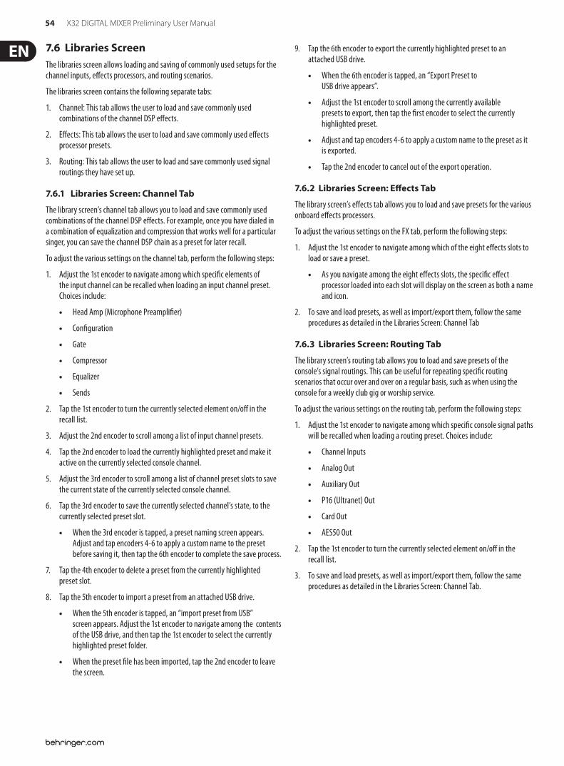
54 X32 DIGITAL MIXER Preliminary User Manual
7.6 Libraries ScreenThe libraries screen allows loading and saving of commonly used setups for the channel inputs, e!ects processors, and routing scenarios.
The libraries screen contains the following separate tabs:
1. Channel: This tab allows the user to load and save commonly used combinations of the channel DSP e!ects.
2. E!ects: This tab allows the user to load and save commonly used e!ects processor presets.
3. Routing: This tab allows the user to load and save commonly used signal routings they have set up.
7.6.1 Libraries Screen: Channel Tab
The library screen’s channel tab allows you to load and save commonly used combinations of the channel DSP e!ects. For example, once you have dialed in a combination of equalization and compression that works well for a particular singer, you can save the channel DSP chain as a preset for later recall.
To adjust the various settings on the channel tab, perform the following steps:
1. Adjust the 1st encoder to navigate among which speci$c elements of the input channel can be recalled when loading an input channel preset. Choices include:
Head Amp (Microphone Preampli$er)
Con$guration
Gate
Compressor
Equalizer
Sends
2. Tap the 1st encoder to turn the currently selected element on/o! in the recall list.
3. Adjust the 2nd encoder to scroll among a list of input channel presets.
4. Tap the 2nd encoder to load the currently highlighted preset and make it active on the currently selected console channel.
5. Adjust the 3rd encoder to scroll among a list of channel preset slots to save the current state of the currently selected console channel.
6. Tap the 3rd encoder to save the currently selected channel’s state, to the currently selected preset slot.
When the 3rd encoder is tapped, a preset naming screen appears. Adjust and tap encoders 4-6 to apply a custom name to the preset before saving it, then tap the 6th encoder to complete the save process.
7. Tap the 4th encoder to delete a preset from the currently highlighted preset slot.
8. Tap the 5th encoder to import a preset from an attached USB drive.
When the 5th encoder is tapped, an “import preset from USB” screen appears. Adjust the 1st encoder to navigate among the contents of the USB drive, and then tap the 1st encoder to select the currently highlighted preset folder.
When the preset $le has been imported, tap the 2nd encoder to leave the screen.
9. Tap the 6th encoder to export the currently highlighted preset to an attached USB drive.
When the 6th encoder is tapped, an “Export Preset to USB drive appears”.
Adjust the 1st encoder to scroll among the currently available presets to export, then tap the $rst encoder to select the currently highlighted preset.
Adjust and tap encoders 4-6 to apply a custom name to the preset as it is exported.
Tap the 2nd encoder to cancel out of the export operation.
7.6.2 Libraries Screen: E#ects Tab
The library screen’s e!ects tab allows you to load and save presets for the various onboard e!ects processors.
To adjust the various settings on the FX tab, perform the following steps:
1. Adjust the 1st encoder to navigate among which of the eight e!ects slots to load or save a preset.
As you navigate among the eight e!ects slots, the speci$c e!ect processor loaded into each slot will display on the screen as both a name and icon.
2. To save and load presets, as well as import/export them, follow the same procedures as detailed in the Libraries Screen: Channel Tab
7.6.3 Libraries Screen: Routing Tab
The library screen’s routing tab allows you to load and save presets of the console’s signal routings. This can be useful for repeating speci$c routing scenarios that occur over and over on a regular basis, such as when using the console for a weekly club gig or worship service.
To adjust the various settings on the routing tab, perform the following steps:
1. Adjust the 1st encoder to navigate among which speci$c console signal paths will be recalled when loading a routing preset. Choices include:
Channel Inputs
Analog Out
Auxiliary Out
P16 (Ultranet) Out
Card Out
AES50 Out
2. Tap the 1st encoder to turn the currently selected element on/o! in the recall list.
3. To save and load presets, as well as import/export them, follow the same procedures as detailed in the Libraries Screen: Channel Tab.
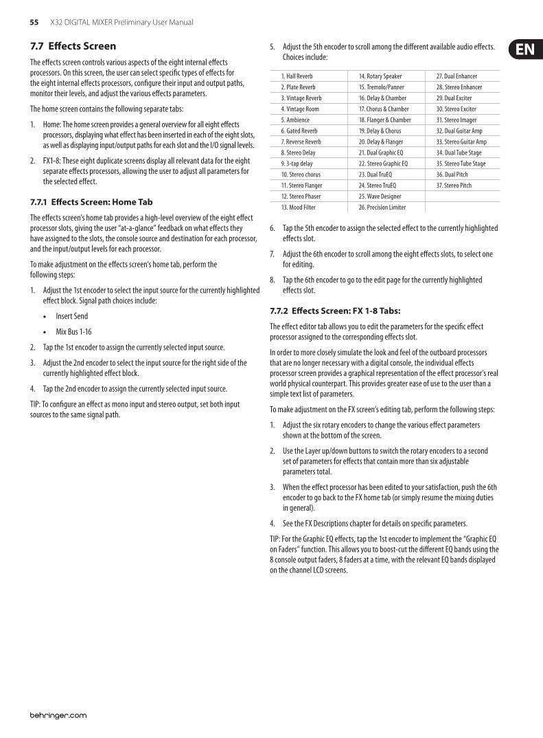
55 X32 DIGITAL MIXER Preliminary User Manual
7.7 E#ects ScreenThe e!ects screen controls various aspects of the eight internal e!ects processors. On this screen, the user can select speci$c types of e!ects for the eight internal e!ects processors, con$gure their input and output paths, monitor their levels, and adjust the various e!ects parameters.
The home screen contains the following separate tabs:
1. Home: The home screen provides a general overview for all eight e!ects processors, displaying what e!ect has been inserted in each of the eight slots, as well as displaying input/output paths for each slot and the I/O signal levels.
2. FX1-8: These eight duplicate screens display all relevant data for the eight separate e!ects processors, allowing the user to adjust all parameters for the selected e!ect.
7.7.1 E#ects Screen: Home Tab
The e!ects screen’s home tab provides a high-level overview of the eight e!ect processor slots, giving the user “at-a-glance” feedback on what e!ects they have assigned to the slots, the console source and destination for each processor, and the input/output levels for each processor.
To make adjustment on the e!ects screen’s home tab, perform the following steps:
1. Adjust the 1st encoder to select the input source for the currently highlighted e!ect block. Signal path choices include:
Insert Send
Mix Bus 1-16
2. Tap the 1st encoder to assign the currently selected input source.
3. Adjust the 2nd encoder to select the input source for the right side of the currently highlighted e!ect block.
4. Tap the 2nd encoder to assign the currently selected input source.
TIP: To con$gure an e!ect as mono input and stereo output, set both input sources to the same signal path.
5. Adjust the 5th encoder to scroll among the di!erent available audio e!ects. Choices include:
6. Tap the 5th encoder to assign the selected e!ect to the currently highlighted e!ects slot.
7. Adjust the 6th encoder to scroll among the eight e!ects slots, to select one for editing.
8. Tap the 6th encoder to go to the edit page for the currently highlighted e!ects slot.
7.7.2 E#ects Screen: FX 1-8 Tabs:
The e!ect editor tab allows you to edit the parameters for the speci$c e!ect processor assigned to the corresponding e!ects slot.
In order to more closely simulate the look and feel of the outboard processors that are no longer necessary with a digital console, the individual e!ects processor screen provides a graphical representation of the e!ect processor’s real world physical counterpart. This provides greater ease of use to the user than a simple text list of parameters.
To make adjustment on the FX screen’s editing tab, perform the following steps:
1. Adjust the six rotary encoders to change the various e!ect parameters shown at the bottom of the screen.
2. Use the Layer up/down buttons to switch the rotary encoders to a second set of parameters for e!ects that contain more than six adjustable parameters total.
3. When the e!ect processor has been edited to your satisfaction, push the 6th encoder to go back to the FX home tab (or simply resume the mixing duties in general).
4. See the FX Descriptions chapter for details on speci$c parameters.
TIP: For the Graphic EQ e!ects, tap the 1st encoder to implement the “Graphic EQ on Faders” function. This allows you to boost-cut the di!erent EQ bands using the 8 console output faders, 8 faders at a time, with the relevant EQ bands displayed on the channel LCD screens.
1. Hall Reverb 14. Rotary Speaker 27. Dual Enhancer2. Plate Reverb 15. Tremolo/Panner 28. Stereo Enhancer3. Vintage Reverb 16. Delay & Chamber 29. Dual Exciter4. Vintage Room 17. Chorus & Chamber 30. Stereo Exciter5. Ambience 18. Flanger & Chamber 31. Stereo Imager6. Gated Reverb 19. Delay & Chorus 32. Dual Guitar Amp7. Reverse Reverb 20. Delay & Flanger 33. Stereo Guitar Amp8. Stereo Delay 21. Dual Graphic EQ 34. Dual Tube Stage9. 3-tap delay 22. Stereo Graphic EQ 35. Stereo Tube Stage10. Stereo chorus 23. Dual TruEQ 36. Dual Pitch11. Stereo Flanger 24. Stereo TruEQ 37. Stereo Pitch12. Stereo Phaser 25. Wave Designer13. Mood Filter 26. Precision Limiter
56 X32 DIGITAL MIXER Preliminary User Manual
7.8 Mute Group ScreenThe mute group screen allows for quick assignment and control of the console’s 6 mute groups, and o!ers two separate functions:
1. It mutes the active screen during the process of assigning channels to mute groups. This ensures that no channels are accidentally muted during the assignment process during a live performance.
2. It o!ers an additional interface for muting/unmuting the mute groups in addition to the dedicated mute group buttons at the bottom of the console.
When activated, the mute screen only covers the bottom portion of the main display, allowing the middle portion to continue displaying its usual screen content.
To assign channels to one of the 6 mute groups, perform the following steps:
1. Press the Mute Group button to switch the main display to the mute groups view.
2. Press and hold the desired mute group button (1-6) on the lower right hand corner of the console.
3. While holding the mute group button, press the select keys of any input or output channel, on any layer, that you wish to assign to the mute group.
4. When you have assigned all the desired channels to the mute group, release the dedicated mute group button. The individual channel mute buttons will resume their normal function.
To use the mute groups screen to mute/unmute the groups, perform the following steps:
1. Tap any of the six encoders to mute the corresponding group, and thus mute all channels that are assigned to that mute group.
2. Tap the encoder of a currently muted group to “un-mute” the mute group.
3. When $nished working with mute groups, tap the Mute Group screen button to exit the mute groups screen. The entire screen will again display its full set of controls for whatever page it was previously on.
57 X32 DIGITAL MIXER Preliminary User Manual
7.9 Utility ScreenThe utility screen is a supplemental screen designed to work in conjunction with the other screens that may be in view at any particular moment. The utility screen is never seen by itself, it always exists in the context of another screen.
To reinforce this point, when the utility screen button is pressed, it illuminates at the same time that another screen button is also illuminated, showing you which screen it is providing extra utilities for. For most screens, pressing the utility button simply acts as a shortcut to a page that can be navigated to by other means. In a few cases, a utility page provides extra utility functions not seen anywhere else.
The utility button works in the following manner with the other screens on the console:
Channel Preamp Screen:
1. Home Page: Takes the user directly to the channel tab of the library screen.
2. Con"g Page: Provides an interface for assigning a custom color, icon, and name to the input or output channel.
Adjust and tap the 6 encoders to assign a color, name, and icon to the currently selected input or output channel. Tap the 6th encoder to exit and save the changes.
By assigning custom names to each channel, which are then displayed in the channel LCD displays, the console achieves superior user-friendliness. For example, Input 1 can display “kick drum” and show a kick drum icon, while output channel 5 can display “Tom’s monitor mix” and show an icon of stage monitor.
3. All other pages: Takes the user directly to the channel tab of the library screen.
USB Screen: Takes the user directly to the “select folder” tab of the USB screen.
Monitor/Talkback Screens: There are no utility functions for any of the di!erent pages of the monitor screen.
Scenes Page: Provides an interface for copying, pasting, loading, and saving di!erent scenes in the scene list. Adjust and tap the six rotary encoders to perform these functions.
Custom Screen: There are no utility functions for any of the di!erent pages of the custom screen.
Meters Screen: There are no utility functions for any of the di!erent pages of the meters screen.
Routing Screen: Takes the user directly to the routing tab of the library screen.
Setup Screen: There are no utility functions for any of the di!erent pages of the setup screen.
Library Screen: There are no utility functions for any of the di!erent pages of the library screen.
E#ects Screen: Takes the user directly to the e!ects tab of the library screen.
58 X32 DIGITAL MIXER Preliminary User Manual
“View” Based Screens
The screens described in the following sections are all “View” based screens. They are navigated to by pressing the “View” button in various sections of the console top panel.
7.10 Monitor/Talkback Screens: The monitor screen is selected by pressing the “View” button of the top panel’s monitor section, as well as the “View” button of the top panel’s talkback section. The screen controls various aspects of the console’s solo bus, control room outputs, and talkback section.
The monitor/talkback screen contains the following separate tabs:
Monitor: This screen controls various solo options, dimming, speaker delay, and sources for the control room output.
Talkback A: This screen controls various adjustments for the talkback A path of console.
Talkback B: This screen controls various adjustments for the talkback B path of console.
Oscillator: This screen o!ers various controls for the onboard oscillator and how it is routed throughout the console.
7.10.1 Monitor/Talkback Screen: Monitor Tab:
The monitor tab controls various console options related to the solo bus, as well as the console’s control room outputs. These options include various solo settings, speaker dimming, speaker delay, and selection of sources for the control room output.
To adjust the various settings on the monitor tab, perform the following steps:
1. Adjust the 1st encoder to change the gain of the monitor signal. This digital gain stage occurs as a $rst preliminary level control, before the top panel’s analog-based monitor level control. A display above the encoder shows the currently set gain value in dB.
A multi-segment level meter is displayed on the color screen to allow for proper gain staging of the monitor signal.
2. Adjust the 2nd encoder to scroll through the various solo methods available to the console when audio is routed to the solo bus. Available options include:
Exclusive (Last): In this mode, pressing another solo button disengages the previous solo.
Solo Follows Select: When this method is selected, the audio of the currently selected channel will automatically be sent to the solo bus. Since a user will often select a channel to adjust its dedicated DSP controls, this method is useful because the audio of the channel will now already be feeding the solo bus where it can be monitored with headphones in a live sound environment.
Select Follows Solo: When this method is selected, any channel that is soloed will automatically become the currently selected channel.
Channel Solo AFL: With this method, the channel and select button do not have any correlation to each other. When a channel’s solo button is pressed, its audio is sent to the solo bus in “after-fader listen” mode, re"ecting the current level of the channel fader and any channel DSP that has been applied.
Mix Bus AFL/PFL: This toggles the AFL/PFL setting for the mix buses when they are soloed (as opposed to the soloing of a single input channel).
DCA Group AFL: This puts the contents of a soloed DCA group into after-fader listen mode when the solo button is pressed on a DCA channel.
Use Master Fader: This allows the Main Fader/mute button to control the solo/mon output.
3. Tap the 2nd encoder to select and assign the currently chosen solo option.
4. Adjust the 3rd encoder to adjust the amount of digital delay that is applied to the control room signal path. The display on the screen will show the current amount of delay in feet, meters, and milliseconds.
5. Tap the 3rd encoder to toggle the delay function on/o!.
TIP: The delay function is useful for aligning the sound of audio monitored through headphones or speakers used at the Front-of-House position with audio that is coming from the stage location.
By delaying the control room audio, it can be brought into alignment with the slightly delayed audio that has to travel from the stage to the Front of House position.
6. Adjust the 4th encoder to set the amount of volume reduction that occurs when the control room bus has its “dim” function enabled. The amount of volume reduction ranges from -40 dB to 0 dB (no change).
7. Tap the 4th encoder to toggle the dim function on/o!.
8. Adjust the 5th encoder to adjust the volume trim for the source currently feeding the control room bus, allowing it to be level/matched with other sources. The amount of trim can be adjusted from -20 dB to +20 dB.
9. Tap the 5th encoder to toggle the control room between mono and stereo operation. This is very useful in a studio context for checking how a mix sounds when played back on a mono speaker such as a clock radio.
10. Adjust the 6th encoder to select what speci$c signal source to monitor in the control room bus. Choices include:
O! (No source)
LR Bus
LR + C/M
LR PFL (pre-fader listen solo bus)
LR AFL (after-fader listen solo bus)
Auxiliary returns 5/6
Auxiliary returns 7/8
11. Tap the 6th encoder to activate the signal source that has been chosen.
59 X32 DIGITAL MIXER Preliminary User Manual
7.10.2 Monitor/Talkback Screen: Talkback Tabs:
The talkback tabs o!er various adjustments for the talkback paths of the console, such as destination of the talkback signal and more.
To adjust the various settings on the Talkback A tab, perform the following steps:
1. The screen displays a multi-segment level meter showing the signal strength of the talkback signal as it has currently been set. It also displays a multi-segment gain reduction meter, showing the user how much compression has been automatically applied to the talkback signal to keep its level even to the recipient.
2. Tap the 1st encoder to enable the talkback circuit. The internal/external talkback microphone will now transmit audio to the Talkback A path’s assigned destination.
3. Tap the 2nd encoder to switch the talkback circuit from the internal talkback to the external microphone connector. A 2nd tap of the encoder switches the console back to using the internal talkback microphone.
4. Adjust the 3rd encoder to set the gain of the talkback A signal. This is an additional gain stage that follows the initial gain stage set by the top panel Talk Level knob.
5. Tap the 3rd encoder to toggle on/o! the talkback circuit’s “auto-dim” function. This function is useful in a studio setting, and will automatically dim the control room outputs when the talkback circuit is active. This prevents a feedback loop from occurring between the talkback microphone and the nearby studio monitors.
6. Adjust the 4th encoder to scroll through the various talkback destinations, which include:
Mix Bus 1-16
LR Bus
Center/Mono Bus
7. Tap the 4th encoder to activate any talkback destination when it is currently selected. Multiple talkback destinations can be selected, allowing the talkback signal to reach many destinations at the same time.
8. Tap the 5th encoder to toggle the dedicated top-panel talkback buttons between latching and non-latching operation.
9. Adjust the 6th encoder to adjust the brightness of the lamp that is connected to the console’s top-panel lamp connector.
10. Tap the 6th encoder to toggle the attached lamp on/o!.
All controls for the talkback B tab work as described above, but pertain to the talkback B signal path.
7.10.3 Monitor/Talkback Screen: Oscillator Tab:
The oscillator tab o!ers controls for the console’s onboard oscillator, a very handy tool that can be used for setting up PA systems and testing various signal "ow paths without the need for a live source feeding a microphone. Settings include oscillator type, frequency, volume, and routing destinations.
To adjust the various settings on the Oscillator tab, perform the following steps:
1. Adjust the 1st encoder to set the level of the onboard oscillator.
2. Tap the 1st encoder to toggle the onboard oscillator on/o!.
The color screen displays a multi-segment level meter that show the current level of the oscillator.
3. Adjust the 2nd encoder to set the frequency of the primary onboard oscillator.
4. Adjust the 3rd encoder to set the frequency of the alternate onboard oscillator.
5. Tap the 3rd encoder to alternate between the 2 onboard oscillators.
6. Adjust the 4th encoder to select the type of oscillator to be used. Choices include:
Sine Wave
Pink Noise
White Noise
7. Tap the 4th encoder to engage the selected oscillator type.
8. Adjust the 6th encoder to select a destination for the onboard oscillator. Choices include:
Mix Bus 1-16
Main L Bus
Main R Bus
Main L+R Bus
Main Center/Mono
Matrix Outputs 1-6
9. Tap the 6th encoder to assign the selected oscillator destination.
60 X32 DIGITAL MIXER Preliminary User Manual
7.11 USB ScreenThe USB screen controls various aspects of the console’s onboard audio $le player/recorder, allowing the user to record stereo audio to an attached USB drive, as well as playback audio $les from the drive through the console.
The USB screen contains the following separate tabs:
Home: This screen provides a general overview of the USB record/playback interface.
Con"g: This screen allows con$guration of the various parameters associated with recording to and playback from the USB drive, such as audio paths, record folders, etc.
7.11.1 USB Screen: Home Tab:
The USB screen’s home tab provides a general overview of the recording/playback process for audio $les residing on the attached USB drive. It o!ers a basic set of transport controls, as well as metering and a list of $les available for playback.
To adjust the various settings on the USB screen’s home tab, perform the following steps:
1. Tap the 1st encoder to stop playback of the audio $le.
2. Tap the 2nd encoder to play back audio from the currently loaded audio $le.
3. Tap the 3rd encoder to rewind the audio.
4. Tap the 4th encoder to fast forward the audio.
5. Tap the 5th encoder to record audio from the currently con$gured audio path, to the attached USB drive.
6. Rotate the 6th encoder to select an audio track from the currently attached USB drive.
7. Tap the 6th encoder to begin playback of the selected audio $le.
A list of available audio $les is displayed on the right hand side of the screen. When the currently loaded track $nishes playback, the next track in the list will begin playback. This allows assorted audio tracks on the USB drive to be played back in sequence and used as “break music” during a break in the band’s set.
The USB screen’s home tab also contains the following helpful displays:
Stereo meter displays for the recorder input level
Stereo output meters for the playback level of the $le currently playing back
A list of available tracks on the attached USB drive
7.11.2 USB Screen: Con!guration Tab
The con$guration tab allows setting up all aspects of the stereo recorder. In this screen, one can select audio paths to feed to the recorder and adjust the level of incoming audio.
To adjust the various settings on the USB screen’s con$guration tab, perform the following steps:
1. Tap the 1st encoder to select a folder to save the recorded audio $les to.
A pop-up window appears, displaying all available folders on the attached drive.
Rotate the $rst encoder to select an available folder.
Tap the $rst encoder to select the currently highlighted folder.
Tap the 2nd encoder to select the folder and return to the main interface.
2. Rotate the 2nd encoder to adjust the input trim for the currently selected channel of the stereo recorder. A stereo input meter on the left side of the screen shows the current input level.
3. Tap the 2nd encoder to select the left or right input of the stereo recorder for further con$guration.
4. Rotate the 3rd encoder to select the category of input to feed to the currently selected channel of the stereo recorder. Choices include:
Main (LRC)
Mix Bus
Matrix
Direct Out
Monitor
61 X32 DIGITAL MIXER Preliminary User Manual
5. Rotate the 4th encoder to select the speci$c signal source to feed the currently selected channel of the stereo recorder. Choices include:
Main L
Main R
Main C/M
Any of the 16 Mix Bus Outputs
Any of the 6 matrix outputs
Any of the 32 direct outputs
Direct Outputs Aux 1-8
Any of the FX Direct Outputs
Monitor L
Monitor R
Talkback
6. Rotate the 5th encoder to select the signal tap point that the selected audio path is tapped from when feeding currently selected channel of the stereo recorder. Choices include:
Pre EQ
Post EQ
Pre-Fader
Post-Fader
7. Tap the 6th encoder to toggle the “playback folder” mode on/o!.
When playback folder mode is OFF, the transport will stop after playing the currently selected audio $le. This is useful for situations like triggering audio cues or sound e!ects in a theatrical setting.
When playback folder mode is ON, the transport will continue playing back all audio $les residing in the currently selected folder one by one. This is useful for playing back several songs during a break in the main set, allowing the attached USB drive to act as a source for “break music”.
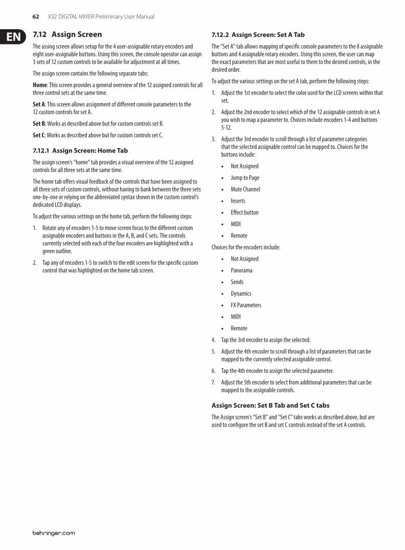
62 X32 DIGITAL MIXER Preliminary User Manual
7.12 Assign ScreenThe assing screen allows setup for the 4 user-assignable rotary encoders and eight user-assignable buttons. Using this screen, the console operator can assign 3 sets of 12 custom controls to be available for adjustment at all times.
The assign screen contains the following separate tabs:
Home: This screen provides a general overview of the 12 assigned controls for all three control sets at the same time.
Set A: This screen allows assignment of di!erent console parameters to the 12 custom controls for set A.
Set B: Works as described above but for custom controls set B.
Set C: Works as described above but for custom controls set C.
7.12.1 Assign Screen: Home Tab
The assign screen’s “home” tab provides a visual overview of the 12 assigned controls for all three sets at the same time.
The home tab o!ers visual feedback of the controls that have been assigned to all three sets of custom controls, without having to bank between the three sets one-by-one or relying on the abbreviated syntax shown in the custom control’s dedicated LCD displays.
To adjust the various settings on the home tab, perform the following steps:
1. Rotate any of encoders 1-5 to move screen focus to the di!erent custom assignable encoders and buttons in the A, B, and C sets. The controls currently selected with each of the four encoders are highlighted with a green outline.
2. Tap any of encoders 1-5 to switch to the edit screen for the speci$c custom control that was highlighted on the home tab screen.
7.12.2 Assign Screen: Set A Tab
The “Set A” tab allows mapping of speci$c console parameters to the 8 assignable buttons and 4 assignable rotary encoders. Using this screen, the user can map the exact parameters that are most useful to them to the desired controls, in the desired order.
To adjust the various settings on the set A tab, perform the following steps:
1. Adjust the 1st encoder to select the color used for the LCD screens within that set.
2. Adjust the 2nd encoder to select which of the 12 assignable controls in set A you wish to map a parameter to. Choices include encoders 1-4 and buttons 5-12.
3. Adjust the 3rd encoder to scroll through a list of parameter categories that the selected assignable control can be mapped to. Choices for the buttons include:
Not Assigned
Jump to Page
Mute Channel
Inserts
E!ect button
MIDI
Remote
Choices for the encoders include:
Not Assigned
Panorama
Sends
Dynamics
FX Parameters
MIDI
Remote
4. Tap the 3rd encoder to assign the selected.
5. Adjust the 4th encoder to scroll through a list of parameters that can be mapped to the currently selected assignable control.
6. Tap the 4th encoder to assign the selected parameter.
7. Adjust the 5th encoder to select from additional parameters that can be mapped to the assignable controls.
Assign Screen: Set B Tab and Set C tabs
The Assign screen’s “Set B” and “Set C” tabs works as described above, but are used to con$gure the set B and set C controls instead of the set A controls.
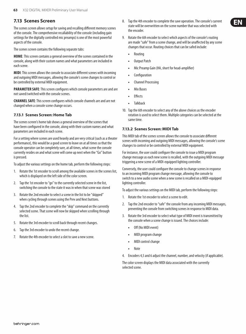
63 X32 DIGITAL MIXER Preliminary User Manual
7.13 Scenes ScreenThe scenes screen allows setup for saving and recalling di!erent memory scenes of the console. The comprehensive recallability of the console (including gain settings for the digitally controlled mic preamps) is one of the most powerful aspects of the console.
The scenes screen contains the following separate tabs:
HOME: This screen contains a general overview of the scenes contained in the console, along with their custom names and what parameters are included in each scene.
MIDI: This screen allows the console to associate di!erent scenes with incoming and outgoing MIDI messages, allowing the console’s scene changes to control or be controlled by external MIDI equipment.
PARAMETER SAFE: This screen con$gures which console parameters are and are not saved/switched with the console scenes.
CHANNEL SAFE: This screen con$gures which console channels are and are not changed when a console scene change occurs.
7.13.1 Scenes Screen: Home Tab
The scenes screen’s home tab shows a general overview of the scenes that have been con$gured in the console, along with their custom names and what parameters are included in each scene.
For a setting where scenes are used heavily and are very critical (such as a theater performance), this would be a good screen to leave on at all times so that the console operator can be completely sure, at all times, what scene the console currently resides on and what scene will come up next when the “Go” button is pressed.
To adjust the various settings on the home tab, perform the following steps:
1. Rotate the 1st encoder to scroll among the available scenes in the scenes list, which is displayed on the left side of the color screen.
2. Tap the 1st encoder to “go” to the currently selected scene in the list, switching the console to the state it was in when that scene was stored
3. Rotate the 2nd encoder to select a scene in the list to be “skipped” when cycling through scenes using the Prev and Next buttons.
4. Tap the 2nd encoder to complete the “skip” command on the currently selected scene. That scene will now be skipped when scrolling through the list.
5. Rotate the 3rd encoder to scroll back through recent changes.
6. Tap the 3rd encoder to undo the recent change.
7. Rotate the 4th encoder to select a slot to save a new scene.
8. Tap the 4th encoder to complete the save operation. The console’s current state will be overwritten on the scene number that was selected with the encoder.
9. Rotate the 6th encoder to select which aspects of the console’s routing are made “safe” from a scene change, and will be una!ected by any scene changes that occur. Routing choices that can be safed include:
Routing
Output Patch
Mic Preamp Gain (HA, short for head-ampli$er)
Con$guration
Channel Processing
Mix Buses
E!ects
Talkback
10. Tap the 6th encoder to select any of the above choices as the encoder rotation is used to select them. Multiple categories can be selected at the same time.
7.13.2 Scenes Screen: MIDI Tab
This MIDI tab of the scenes screen allows the console to associate di!erent scenes with incoming and outgoing MIDI messages, allowing the console’s scene changes to control or be controlled by external MIDI equipment.
For instance, the user could con$gure the console to issue a MIDI program change message as each new scene is recalled, with the outgoing MIDI message triggering a new scene of a MIDI-equipped lighting controller.
Conversely, the user could con$gure the console to change scenes in response to an incoming MIDI program change message, allowing the console to switch to a new audio scene when a new scene is recalled on a MIDI-equipped lighting controller.
To adjust the various settings on the MIDI tab, perform the following steps:
1. Rotate the 1st encoder to select a scene to edit.
2. Tap the 2nd encoder to “safe” the console from any incoming MIDI messages, preventing the console from switching scenes in response to MIDI data.
3. Rotate the 3rd encoder to select what type of MIDI event is transmitted by the console when a scene change is issued. The choices include:
O! (No MIDI event)
MIDI program change
MIDI control change
Note
4. Encoders 4,5 and 6 adjust the channel, number, and velocity (if applicable).
The color screen displays the MIDI data associated with the currently selected scene.
64 X32 DIGITAL MIXER Preliminary User Manual
7.13.3 Scenes Screen: Parameter Safe Tab
The scenes screen’s “parameter safe” tab con$gures which console parameters are and are not saved/switched with the console scenes. This is very useful when the operator has certain parameters that they wish to remain in control of, and would never want to have altered during a scene change, for example, the mic pre gains on the input channels.
To adjust the various settings on the Parameter Safe tab, perform the following steps:
1. Rotate any of the $rst 4 encoders to navigate among the checkboxes in the color screen, which represent various console areas that can be isolated from scene changes.
2. Tap any of the $rst 4 encoders to select the console areas that have been selected with the encoders. In each of the four columns, multiple console areas can be selected and isolated from scene changes.
The following areas of the console can be isolated from scene changes, and are divided up into 4 columns on the color screen:
Column 1: Input Channels
HA (Head Amp/Microphone Preamp)
Con$guration
Channel Equalizer
Channel Gate/Compressor
Channel Insert
Channel Groups
Fader, Pan, Mute, Mix Ons
Column 2: Input Channels
Mix sends 1-16
Column 3: Mix Buses
Mix sends 1-16
Con$guration
Equalizer
Compressor
Insert
Groups
Fader, Pan, Mute, Matrix Ons
Column 4: Console
Con$guration
Solo
Routing
Output Patch
7.13.4 Scenes Screen: Channel Safe Tab
The scenes screen’s “channel safe” tab con$gures which console channels are and are not changed when a console scene change occurs. This allows the user to “protect” certain channels from ever changing during a scene change, giving them as much control as possible for key audio sources.
For example, in a theater context, the console operator may have dialed in just the right EQ and compressor settings and channel volume for the voice of the lead actor, and does not wish to have them altered when the console changes scenes and alters various parameters.
To adjust the various settings on the Channel Safe tab, perform the following steps:
1. Rotate any of the 6 encoders to navigate among the check boxes in the color screen, which represent various groups of channels that can be isolated from scene changes.
2. Tap any of the 6 encoders to select the console areas that have been highlighted with the encoders. In each of the 6 columns, multiple console areas can be selected and isolated from scene changes.
The following areas of the console can be isolated from scene changes, and are divided up into six columns on the color screen:
Column 1: Channels
Input Channels 1-16
Column 2: Channels
Input Channels 17-32
Column 3: Buses
Aux 1-8
FX 1L through 4R
Column 4: Returns
Mix 1-16
Column 5: Main/Matrix/Groups
Matrix 1-6
LR Bus
Center/Mono Bus
DCA groups 1-8
Column 6: E!ects Slots
FX 1-8
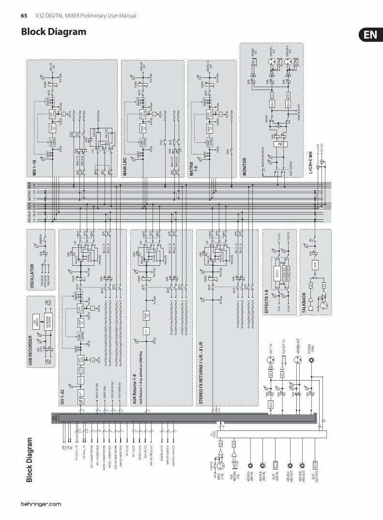
65 X32 DIGITAL MIXER Preliminary User Manual
Block DiagramM
AIN
L R
C L
R
SOLO
MA
TR
IX
1 2
5 6
MIX
BU
S
1 2
15 1
6
FADE
R
MIX
1–1
6
INSE
RT6-
BAND
EQ
INSE
RTCO
MP/
EXP
AN
KEY-
IN
Pre
EQPo
st EQ
EQPr
e Fa
der
Post
Fade
r
Mat
rix 1
,3,5
MUT
E
MUT
E
SOLO
Post
Fade
r
Post
Fade
r
Post
Fade
r
Post
Fade
r
Mat
rix 2
,4,6
MIX
1-1
6OU
T
16
EFFE
CTS
1-8
EFFE
CT
31 B
AND
GEQ
31 B
AND
GEQ
FX O
UT L
FX O
UT R
FX IN
L
FX IN
R
USB
PLAY
USB
REC
USB
REC
OR
DER
REC
LEVE
L
USB
MEM
ORY
USB
MEM
ORY
RECO
RDER
L+C
/R+C
MIX
L+C
OUT
R+C
OUT
++
DSP
PATC
H
USB
PLAY
USB
REC
FX 1
-8 O
UT (L
/ R)
FX 1
-8 IN
(L /
R)
6168 x 2
8 x 2
MIX
1-1
6 IN
SERT
RET
URN
16 M
IX 1
-16
INSE
RT S
END
16 M
IX 1
-16
OUT
MAI
N LR
C IN
SERT
RET
URN
MAT
RIX
1-6
INSE
RT R
ETUR
N
6M
ATRI
X 1-
6 IN
SERT
SEN
D
6M
ATRI
X 1-
6 OU
T
33M
AIN
LRC
INSE
RT S
END
3M
AIN
LRC
OUT
3M
AIN
LRC
PRE
EQ O
UT
PATC
H CU
E
MON
ITOR
LR
OUT
2M
ONIT
OR L
+C/R
+C O
UT
22
MON
ITOR
SOU
RCE
IN
I/OPA
TCH
A/D
INPU
T(1
-32)
AES-
50 A
(48c
h IN
)
AES-
50 B
(48c
h IN
)
SLOT
(32c
h IN
)
AES-
50 A
(48c
h OU
T)
AES-
50 B
(48c
h OU
T)
SLOT
(32c
h OU
T)
40 16
AU
X RE
TURN
(1
-6)
+48V
PHAN
TOM
A/D
TALK
BA
CK
COM
P
ONGA
IN
+48V
A/D
A/D
P16
BUS
(16c
h)
D/A
OUT
1-16
D/A
AUX
OUT
1-6
DELA
Y
GAIN
GAIN
GAIN
AES/
EBU
OUT
GAIN
8
AU
X R
etur
ns 1
–8A
UX
Ret
urns
7–8
by
defa
ult o
n U
SB P
lay
Pre
EQ
Pre
EQ/P
re F
ader
/Pos
t Fad
er/P
ost P
an L
Pre
EQ/P
re F
ader
/Pos
t Fad
er/P
ost P
an R
Pre
Fade
r
Mix
1,3.
..15
Mix
2,4.
..16
SOLO
4BAN
DEQ
ATT
Pre
EQ/P
re F
ader
/Pos
t Fad
er/P
ost P
an L
Pre
EQ/P
re F
ader
/Pos
t Fad
er/P
ost P
an R
MUT
EMUT
E
FADE
RLC
RPA
N (L
R)
PAN
(LCR
)GA
IN
Post
Fade
rPo
st Pa
nGAIN
32 32 32 32 32
ATT
CH
1–3
2
LOW
CUT
GATE
/DU
CK
INSE
RT4-
BAND
EQ
INSE
RTCO
MP/
EXP
ANDE
LAY
KEY-
IN
Pre
EQPo
st EQ
EQ
Pre
Fade
r
Mix
1,3.
..15
Mix
2,4.
..16
Pre
HP/P
re G
ate/
Post
Gate
/Pre
EQ/
Post
EQ/P
re F
ader
/Pos
t Fad
er/P
ost P
an L
Pre
HP/P
re G
ate/
Post
Gate
/Pre
EQ/
Post
EQ/P
re F
ader
/Pos
t Fad
er/P
ost P
an R
KEY-
IN
EQ
Pre
HP/P
re G
ate/
Post
Gate
/Pre
EQ/
Post
EQ/P
re F
ader
/Pos
t Fad
er/P
ost P
an L
Pre
HP/P
re G
ate/
Post
Gate
/Pre
EQ/
Post
EQ/P
re F
ader
/Pos
t Fad
er/P
ost P
an R
SOLO
INSE
RT R
ETUR
N
INSE
RT S
END
PRE
LOW
CUT
OUT
POST
FAD
ER O
UT
MUT
EMUT
E
FADE
RLC
RPA
N (L
R)
PAN
(LCR
)GA
IN
Post
Fade
rPo
st Pa
nGAIN
COM
P/ E
XPAN
8 x 2
STER
EO F
X R
ETU
RN
S 1
L/R
– 8
L/R
Pre
Fade
r/Pos
t Fad
er/P
ost P
an L
Pre
Fade
r/Pos
t Fad
er/P
ost P
an R
Pre
Fade
r
Mix
1,3.
..15
Mix
2,4.
..16
SOLO
Pre
Fade
r/Pos
t Fad
er/P
ost P
an L
Pre
Fade
r/Pos
t Fad
er/P
ost P
an R
MUT
EMUT
EFA
DER
LCR
PAN
(LR)
PAN
(LCR
)GA
IN
Post
Fade
rPo
st Pa
nGAIN
WHI
TE N
OISE
PINK
NOI
SE
OSC
ILLA
TOR
SINE
WAV
E
GENE
RATE
GAIN
COM
P/ E
XPAN
LCR
PAN
(LR)
PAN
(LCR
)
GAIN
GAIN GA
IN
+
MO
NO
MON
ITOR
LR
OUT
DELA
Y
DELA
Y
MO
NIT
OR
D/A
PHON
ES
OUT
MON
ITOR
L
OU
T
D/A
MON
ITOR
R
OU
TSO
LO /
SOUR
CE
MON
ITOR
SOU
RCE
IN
DIM
2
GAIN
GAIN
GAIN
FADE
R
MA
TRIX
1-6
INSE
RTIN
SERT
KEY-
IN
Pre
EQPo
st EQ
EQPr
e Fa
der
Post
Fade
r
MUT
E
SOLO
MAT
RIX
1-6
OUT
Post
Fade
r
COM
P/ E
XPAN
EQ6B
AND
COM
P/ E
XPAN
FADE
R
MA
IN L
RC IN
SERT
6BAN
DEQ
INSE
RTCO
MP/
EXP
AN
KEY-
IN
Pre
EQPo
st EQ
EQ
GAIN
Pre
Fade
rPo
st Fa
der
Mat
rix 1
,3,5
MUT
E
MUT
E
SOLO
Post
Fade
r
Post
Fade
r
Post
Fade
rM
atrix
2,4
,6
MAI
N LR
COU
TCO
MP/
EXP
AN
mut
e
mut
e
mut
e
mut
e
mut
e
mut
e
mut
e
mut
e
mut
e
stere
o
mon
o
stere
o
mut
e
stere
o
mon
o
stere
o
stere
o
mon
o
stere
o
stere
o
mon
o
stere
o
Bloc
k Di
agra
m
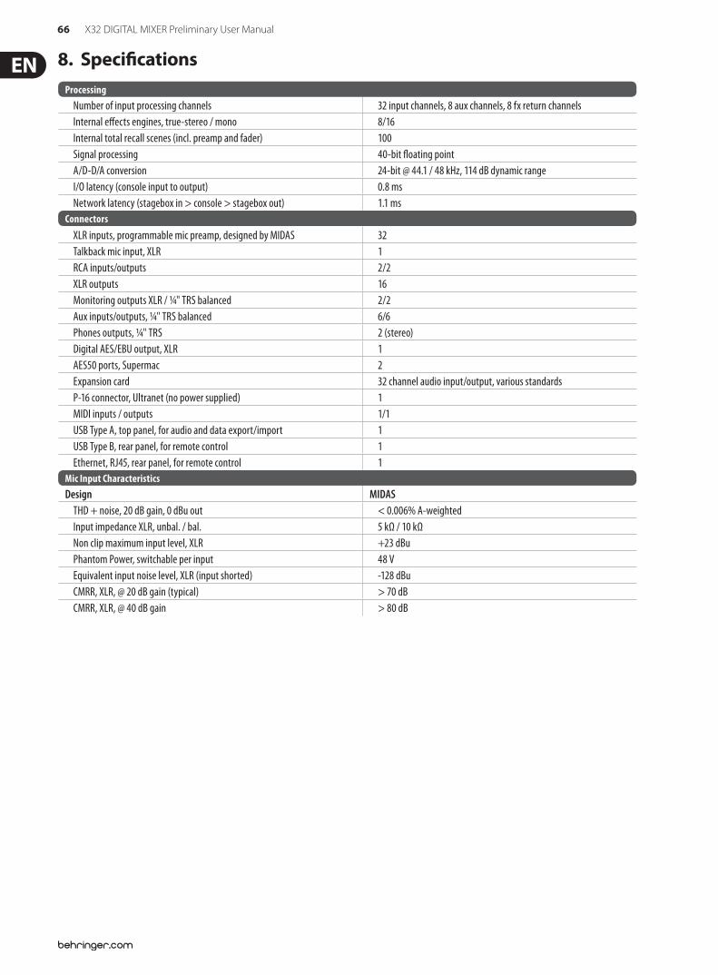
66 X32 DIGITAL MIXER Preliminary User Manual
8. Speci!cationsProcessing
Number of input processing channels 32 input channels, 8 aux channels, 8 fx return channelsInternal e!ects engines, true-stereo / mono 8/16Internal total recall scenes (incl. preamp and fader) 100Signal processing 40-bit "oating pointA/D-D/A conversion 24-bit @ 44.1 / 48 kHz, 114 dB dynamic rangeI/O latency (console input to output) 0.8 msNetwork latency (stagebox in > console > stagebox out) 1.1 ms
ConnectorsXLR inputs, programmable mic preamp, designed by MIDAS 32Talkback mic input, XLR 1RCA inputs/outputs 2/2XLR outputs 16Monitoring outputs XLR / ¼" TRS balanced 2/2Aux inputs/outputs, ¼" TRS balanced 6/6Phones outputs, ¼" TRS 2 (stereo)Digital AES/EBU output, XLR 1AES50 ports, Supermac 2Expansion card 32 channel audio input/output, various standardsP-16 connector, Ultranet (no power supplied) 1MIDI inputs / outputs 1/1USB Type A, top panel, for audio and data export/import 1USB Type B, rear panel, for remote control 1Ethernet, RJ45, rear panel, for remote control 1
Mic Input Characteristics Design MIDAS
THD + noise, 20 dB gain, 0 dBu out < 0.006% A-weighted Input impedance XLR, unbal. / bal. 5 kΩ / 10 kΩ Non clip maximum input level, XLR +23 dBu Phantom Power, switchable per input 48 V Equivalent input noise level, XLR (input shorted) -128 dBu CMRR, XLR, @ 20 dB gain (typical) > 70 dB CMRR, XLR, @ 40 dB gain > 80 dB
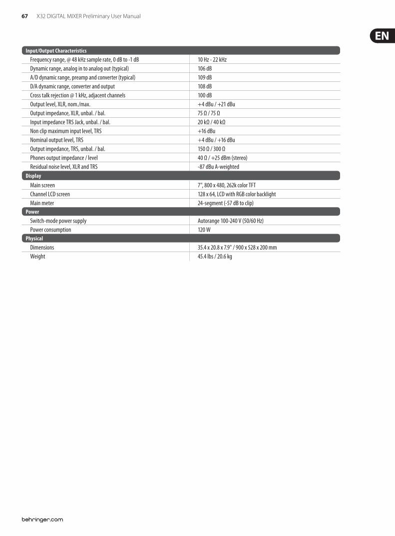
67 X32 DIGITAL MIXER Preliminary User Manual
Input/Output Characteristics Frequency range, @ 48 kHz sample rate, 0 dB to -1 dB 10 Hz - 22 kHz Dynamic range, analog in to analog out (typical) 106 dB A/D dynamic range, preamp and converter (typical) 109 dB D/A dynamic range, converter and output 108 dB Cross talk rejection @ 1 kHz, adjacent channels 100 dB Output level, XLR, nom./max. +4 dBu / +21 dBu Output impedance, XLR, unbal. / bal. 75 Ω / 75 Ω Input impedance TRS Jack, unbal. / bal. 20 kΩ / 40 kΩ Non clip maximum input level, TRS +16 dBu Nominal output level, TRS +4 dBu / +16 dBu Output impedance, TRS, unbal. / bal. 150 Ω / 300 Ω Phones output impedance / level 40 Ω / +25 dBm (stereo) Residual noise level, XLR and TRS -87 dBu A-weighted
Display
Main screen 7", 800 x 480, 262k color TFTChannel LCD screen 128 x 64, LCD with RGB color backlightMain meter 24-segment (-57 dB to clip)
PowerSwitch-mode power supply Autorange 100-240 V (50/60 Hz)Power consumption 120 W
PhysicalDimensions 35.4 x 20.8 x 7.9" / 900 x 528 x 200 mmWeight 45.4 lbs / 20.6 kg
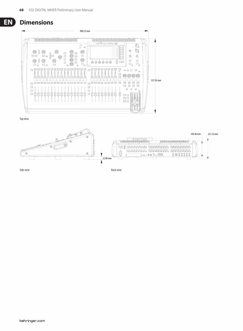
68 X32 DIGITAL MIXER Preliminary User Manual
Dimensions
22.00 mm
169.46 mm 221.33 mm
527.05 mm
900.23 mm
Top view
22.00 mm
169.46 mm 221.33 mm
527.05 mm
900.23 mm
Side view Back view
69 X32 DIGITAL MIXER Preliminary User Manual
FEDERAL COMMUNICATIONS COMMISSION COMPLIANCE INFORMATION
Responsible Party Name: MUSIC Group Services US Inc.
Address: 18912 North Creek Parkway, Suite 200 Bothell, WA 98011, USA
Phone/Fax No.: Phone: +1 425 672 0816 Fax: +1 425 673 7647
X32 DIGITAL MIXER
complies with the FCC rules as mentioned in the following paragraph:
This equipment has been tested and found to comply with the limits for a Class B digital device, pursuant to part 15 of the FCC Rules. These limits are designed to provide reasonable protection against harmful interference in a residential installation. This equipment generates, uses and can radiate radio frequency energy and, if not installed and used in accordance with the instructions, may cause harmful interference to radio communications. However, there is no guarantee that interference will not occur in a particular installation. If this equipment does cause harmful interference to radio or television reception, which can be determined by turning the equipment o! and on, the user is encouraged to try to correct the interference by one or more of the following measures:
Reorient or relocate the receiving antenna.
Increase the separation between the equipment and receiver.
Connect the equipment into an outlet on a circuit di!erent from that to which the receiver is connected.
Consult the dealer or an experienced radio/TV technician for help.
This device complies with Part 15 of the FCC rules. Operation is subject to the following two conditions:
(1) this device may not cause harmful interference, and (2) this device must accept any interference received, including interference that may cause undesired operation.
Important information:
Changes or modi$cations to the equipment not expressly approved by MUSIC Group can void the user’s authority to use the equipment.
X32 DIGITAL MIXER

We Hear You


![X32-20060116-009R1 SBBC TX Stage-3 QoS Mapping [LU]](https://img.pdfslide.us/doc/110x75/577cc2bd1a28aba711947602/x32-20060116-009r1-sbbc-tx-stage-3-qos-mapping-lu.jpg)