Embed Size (px)
Citation preview
X-Rack Owner’s Manual

Super-Analogue™ Outboard
Owner’s Manual
82S6XR010C
Solid State LogicS O U N D | | V I S I O N
SUPERANALOGUEX - R A C K
X-Rack Owner’s Manual
As research and development is a continual process, Solid State Logic reserves the rightto change the features and specifications described herein without notice or obligation
E&OE
Initial Release (Rev. 0A), September 2005Added Mic Amp and EQ Modules (Rev. 0B), April 2006
Added Line Return and Master Modules (Rev. 0C), October 2006
Solid State LogicS O U N D | | V I S I O N
Begbroke, Oxford, England, OX5 1RU • +44 (0)1865 842300
320 West 46th Street, 2nd Floor, New York, NY 10036, USA • +1 (1) 212 315 1111Suite 401, 5757 Wilshire Blvd, Los Angeles, CA 90036, USA • +1 (1) 323 549 90903-55-14 Sendagaya, Shibuya-Ku, Tokyo 151-0051, Japan • +81 (0)3 5474 1144
7 bis, rue de la Victoire, le Blanc Mesnil, Paris 93150, France • +33 (0)1 48 67 84 85Via Timavo 34, 20124 Milano, Italy • +39 (0)39 2328 094
Visit SSL at URL: http://www.solid-state-logic.com
© Solid State LogicAll Rights reserved under International and Pan-American Copyright Conventions
Solid State Logic, SSL and XLogic are trademarks of Solid State Logic
All other product names and trademarks are the property of their respective owners
No part of this publication may be reproduced in any form orby any means, whether mechanical or electronic, without thewritten permission of Solid State Logic, Oxford, England
Page 1
Contents
1. Introduction 3
2. Safety Considerations 42.1 Definitions 42.2 Electrical Safety Warning 42.3 Installation 42.4 Graphical Symbols 4
3. X-Rack Installation 63.1 Assembling the X-Rack 63.2 Mounting 63.3 Connection 73.3.1 Power Connection 73.3.2 Audio Connection 73.3.3 Connection to an AWS 900 73.3.4 MIDI Connection 73.3.5 Mix Bus Link 7
4. X-Rack Operation – Total Recall 84.1 Overview 84.2 Standalone Mode 84.2.1 Saving Stores to Internal Memory 84.2.2 Recalling Stores 84.2.3 Exiting Display Mode 84.2.4 Copy/Swap 94.2.5 Deleting Stores 94.2.6 Delete all Stores 9
4.3 AWS Remote Mode 94.3.1 System Requirements 94.3.2 Operation 9
4.4 Setup/MIDI mode 104.4.1 Overview 104.4.2 MIDI Save and Load 114.4.3 Write Protect 124.4.4 Remote Mode 124.4.5 Address Setting 124.4.6 Show Version 124.4.7 Test Mode 13
4.5 Software Download and Installation 13
5. Miscellaneous 165.1 Internal Links and Fuses 165.2 Connector Details 165.3 Physical Specification 175.4 Environmental Specification 17
A Mic Amp Module A-1B EQ Module B-1D Dynamics Module D-1E Line Return Module E-1F Master Module F-1

Page 2
X-Rack Owner’s Manual
Solid
Sta
te L
ogic
OX
FOR
D •
EN
GLA
ND
ogic
XL
SUPE
RA
NA
LOG
UE
X -
R A
C K
SE
TU
P/
M
IDI
SA
VE
Pu
sh t
o S
elec
t
CO
PY
/ D
EL
TOTA
L R
ECA
LL Em
pty
Wr
Pro
t
SE
L
XR
621
MIC
INS
T
IMP
+48V
PA
D
LIN
E
LIN
E
fl
HF
IN
IN
IN
RE
C
RE
C
L
R
GN
D
LIF
T
INS
TR
UM
EN
T
OU
TP
UT
SIG
NA
L
LF
Z
LO
H
I
dB
+7
5 +1
2
+20
-20
dB
KH
z
9 6 3
50
30
4
30
600
60 16
0 30
0
SE
L
XR
621
MIC
INS
T
IMP
+48V
PA
D
LIN
E
LIN
E
fl
HF
IN
IN
IN
RE
C
RE
C
L
R
GN
D
LIF
T
INS
TR
UM
EN
T
OU
TP
UT
SIG
NA
L
LF
Z
LO
H
I
dB
+7
5 +1
2
+20
-20
dB
KH
z
9 6 3
50
30
4
30
600
60 16
0 30
0
SE
L
XR
625
HF
d
B
HM
F
LM
F
dB
dB
LF
d
B
Q
Q
- +
- +
- +
- +
IN
G-E
Q
KH
z
KH
z
22
1.5
10
5
2 15
7 .6
3 2
1 5
Hz
KH
z
2.0
.2
1.0
.6
.3
1.6
600
40
220
60
SE
L
XR
625
HF
d
B
HM
F
LM
F
dB
dB
LF
d
B
Q
Q
- +
- +
- +
- +
IN
G-E
Q
KH
z
KH
z
22
1.5
10
5
2 15
7 .6
3 2
1 5
Hz
KH
z
2.0
.2
1.0
.6
.3
1.6
600
40
220
60
SE
L
+10
-30
CO
MP
RE
SS
OR
GA
TE
/ E
XP
AN
DE
R
KE
Y
4 0.
1 RE
LE
AS
E
0.1
4
+10 TH
RE
SH
OL
D
-20
RA
TIO
1 ∞
RA
NG
E
0 40
PK
FA
ST
A
TT
LIN
K
RE
LE
AS
E
TH
RE
SH
OL
D
IN
EX
P
20
14
10
6 3
HO
LD
0 4
FA
ST
A
TT
XR
618
SE
L
+10
-30
CO
MP
RE
SS
OR
GA
TE
/ E
XP
AN
DE
R
KE
Y
4 0.
1 RE
LE
AS
E
0.1
4
+10 TH
RE
SH
OL
D
-20
RA
TIO
1 ∞
RA
NG
E
0 40
PK
FA
ST
A
TT
LIN
K
RE
LE
AS
E
TH
RE
SH
OL
D
IN
EX
P
20
14
10
6 3
HO
LD
0 4
FA
ST
A
TT
XR
618
SE
L
XR
623 LE
VE
L
PA
N
INS
RE
C
SOLO
LIN
E 1 L
EV
EL
PA
N
INS
RE
C
SOLO
LIN
E 2 L
EV
EL
PA
N
INS
RE
C
SOLO
LIN
E 3 L
EV
EL
PA
N
INS
RE
C
SOLO
LIN
E 4
SE
L
XR
622
MIX
LE
VE
L
AF
L
LE
VE
L
MIX
RE
C
MO
NIT
OR
SU
M
MO
N
SU
M
INS
INS
RE
C
MIX
EX
T
AL
T
MO
NO
SO
LO
DIM
CU
T M
ON
ITO
R
0 3 6 9 12 15 18 24 30 36 42 48
CA
UT
ION
RIS
K O
F E
LEC
TR
IC S
HO
CK
DO
NO
T O
PE
N
Thi
s eq
uipm
ent m
ust b
e E
arth
ed. R
efer
to
man
ual f
or in
stal
latio
n in
stru
ctio
ns.
CA
UT
ION
! D
isco
nnec
t all
pow
er s
ourc
es
befo
re r
emov
ing
any
pane
l(s).
WA
RN
ING
! U
near
thed
met
al p
arts
may
be
pres
ent i
nsid
e en
clos
ure.
Che
ck fo
r ha
zard
ous
volta
ges
befo
re to
uchi
ng.
For
pro
tect
ion
agai
nst r
isk
of fi
re -
rep
lace
on
ly w
ith s
ame
type
/rat
ing
of fu
se.
Do
not e
xpos
e to
rai
n or
moi
stur
e.
No
user
-ser
vica
ble
part
s in
side
- to
be
serv
iced
onl
y by
qua
lifie
d pe
rson
nel.
12
34
56
78
TO
TA
L R
EC
AL
LL
INK
IN
MID
I IN
M
IDI O
UT
TO
TA
L R
EC
AL
LL
INK
OU
T
Thi
s de
vice
com
plie
s w
ith p
art 1
5 of
the
FC
C R
ules
. O
pera
tion
is s
ubje
ct to
the
follo
win
g tw
o co
nditi
ons:
(1)
Thi
s de
vice
may
not
cau
se h
arm
ful i
nter
fere
nce,
and
(2)
Thi
s de
vice
mus
t acc
ept a
ny in
terfe
renc
e re
ceiv
ed,
inc
ludi
ng in
terfe
renc
e th
at m
ay c
ause
und
esire
d op
erat
ion.
Thi
s cl
ass
A d
igita
l app
arat
us c
ompl
ies
with
Can
adia
n IC
ES
-003
MIX
BU
S L
INK
OU
T
IN
+4dB
u-1
0dB
V
KE
Y
OU
T
IN
+4dB
u-1
0dB
V
KE
Y
OU
T
IN
+4dB
u-1
0dB
V
OU
T
IN
+4dB
u-1
0dB
V
IN OU
T
LIN
E
IN OU
T
LIN
E
LIN
E IN
INS
ER
TS
EN
D/
RT
N1
- 4
INS
RTN
EX
TM
ON
ALT
MO
N
INS
SN
DM
IXR
EC
FO
L M
ON
TE
ST
ED
DA
TE
INIT
IALS
(I
EC
12
7)
Mod
el
Ser
ial N
o.
Sol
id S
tate
Log
ic
Oxf
ord
¥ E
ngla
nd
F
US
E r
isk
of
fire
, u
se s
am
e t
ype
a
nd
ra
ting
2
50
V
2
50
V
R
atin
gs:
AC
~ 5
0/6
0H
z
V
olts
Am
ps
629935X1
XRK001
100-240 0.5-0.2
NONE
Page 3
Introduction
1. Introduction
OverviewThe Solid State Logic X-Rack unit has been developed from the successful range of XLogic outboard equipmentand provides a flexible solution to those engineers requiring a larger number of processing units in a compactpackage.The additional space provided by the X-Rack allows the processing modules to be vertically orientated,providing a more familiar interface to users of Solid State Logic’s renowned range of mixing consoles, and makesit possible to include Solid State Logic’s Total Recall system - the first time this has been available on an analogueoutboard unit.
This ManualThe object of this manual is to provide purchasers of the X-Rack unit with information in the following areas:
• Operation of the unit• Safety considerations• Installation requirements• Electrical connections and cabling• Connector pin-outs• Specifications and physical dimensions
This manual is applicable to X-Rack units from serial number XRK110 onwards and assumes that the X-Rack unitis running V1.2/0 or later software. Please refer to Section 4 of this manual for instructions on how to check thecurrent software version and how to obtain and install a newer version if required.
WarrantyThe warranty period for this unit is 12 months from date of purchase.
In Warranty RepairsIn the event of a fault during the warranty period the unit must be returned to your local distributor who willarrange for it to be shipped to Solid State Logic for repair. All units should be shipped to Solid State Logic in theiroriginal packaging. Solid State Logic cannot be held responsible for any damage caused by shipping units inother packaging. In such cases Solid State Logic will return the unit in a suitable box, which you will be chargedfor. Please do not send manuals, power leads or any other cables – Solid State Logic can not guarantee to returnthem to you. Please also note that warranty returns will only be accepted as such if accompanied by a copy of thereceipt or other proof of purchase.
Out of Warranty RepairsIn the event of a fault after the warranty period has expired, return the unit in its original packaging to your localdistributor for shipment to Solid State Logic. You will be charged for the time spent on the repair (at Solid StateLogic's current repair rate) plus the cost of parts and shipping.

Page 4
X-Rack Owner’s Manual
2. Safety considerations
This section contains definitions and warnings, and practical information to ensure a safe working environment.Please take time to read this section before undertaking any installation work.
2.1 Definitions‘Maintenance’
All maintenance must be carried out by fully trained personnel. Note: it is advisable to observe suitable ESDprecautions when maintenance to any part is undertaken.
‘Non-User Adjustments’
Adjustments or alterations to the equipment may affect the performance such that safety and/or internationalcompliance standards may no longer be met. Any such adjustments must therefore only be carried out by fullytrained personnel.
‘Users’
This equipment is designed for use solely by engineers and competent operators skilled in the use of professionalaudio equipment.
‘Environment’
This product is a Class A product intended to form an integrated component part of a professional audiorecording, mixing, dubbing, film, TV, radio broadcast or similar studio wherein it will perform to specificationproviding that it is installed according to professional practice.
2.3 Installation
Voltage Selection and FusingThe X-Rack unit has an auto-sensing power supply that can operate on 100 – 230V without adjustment.The X-Rack power supply module is internally fused. If the fuse should fail for any reason the unit should bereturned to Solid State Logic for repair/replacement as appropriate.
Safety Earth ConnectionAny mains powered item of Solid State Logic equipment that is supplied with a 3-core mains lead (whetherconnectorised or not) should always have the earth wire connected to the mains supply ground. This is the safetyearth and grounds the exposed metal parts of the racks and cases and should not be removed for any reason.Note that the earth stud provided on the rear of the equipment is a functional earth not a safety earth.
2.2 Electrical Safety WarningWhen installing or servicing any item of Solid State Logic equipment with power applied, when coverand/or blank panels are removed, HAZARDOUS CONDITIONS CAN EXIST.
These hazards include: High voltagesHigh energy stored in capacitorsHigh currents available from DC power bussesHot component surfaces
Any metal jewellery (watches, bracelets, neck-chains and rings) that could inadvertently come into contactwith uninsulated parts should always be removed before reaching inside powered equipment.
Page 5
Safety Considerations
Mains Supply and PhasesSolid State Logic equipment is designed for connection to single phase supplies with the Neutral conductor atearth potential – category TN – and is fitted with a protective fuse in the Live conductor only. It is not designedfor use with Phase (Live) and Neutral connections reversed or where the Neutral conductor is not at earthpotential (TT or IT supplies).Mains cables will be coded with the following colour scheme:
LIVE: BrownNEUTRAL: BlueEARTH: Yellow/Green
Mains Isolation and Over-Current ProtectionAn external disconnect device is required for this equipment; a detachable power cord, as fitted to thisequipment, is a suitable disconnect device. Note that the socket outlet used for the detachable power cord shouldbe installed near the equipment and should be easily accessible.An external over-current protection device is required to protect the wiring to this equipment which must beinstalled according to current wiring regulations. The fusing or breaking-current is defined in the environmentalspecification in Section 5.0 of this manual. In certain countries this function is supplied by use of a fused plug.
CE CertificationNote that the majority of cables supplied with Solid State Logic equipment are fitted with ferrite ringsat each end. This is to comply with current European CE regulations and these ferrites should not beremoved. If any of the equipment metalwork is modified in any way the CE certification status of theproduct may be adversely affected.
Note that a frame or chassis terminal stud (functional earth) has been fitted to this equipment to provide aconvenient low impedance bonding point for interconnected equipment, should it be required.
FCC CertificationThe XLogic unit has been tested and found to comply with the limits for a Class Adigital device, pursuant to part15 of the FCC Rules. These limits are designed to provide reasonable protection against harmful interferencewhen the equipment is operated in a commercial environment. This equipment generates, uses, and can radiateradio frequency energy and, if not installed and used in accordance with the instruction manual, may causeharmful interference to radio communications. Operation of this equipment in a residential area is likely to causeharmful interference in which case the user will be required to correct the interference at his own expense.
Instructions for Disposal of WEEE by Users in the European UnionThe symbol shown here is on the product or on its packaging, which indicates that this productmust not be disposed of with other waste. Instead, it is the user’s responsibility to dispose oftheir waste equipment by handing it over to a designated collection point for recycling of wasteelectrical and electronic equipment. The separate collection and recycling of your wasteequipment at the time of disposal will help to conserve natural resources and ensure that it isrecycled in a manner that protects human health and the environment. For more informationabout where you can drop off your waste equipment for recycling, please contact your local cityoffice, your household waste disposal service or where you purchased the product.
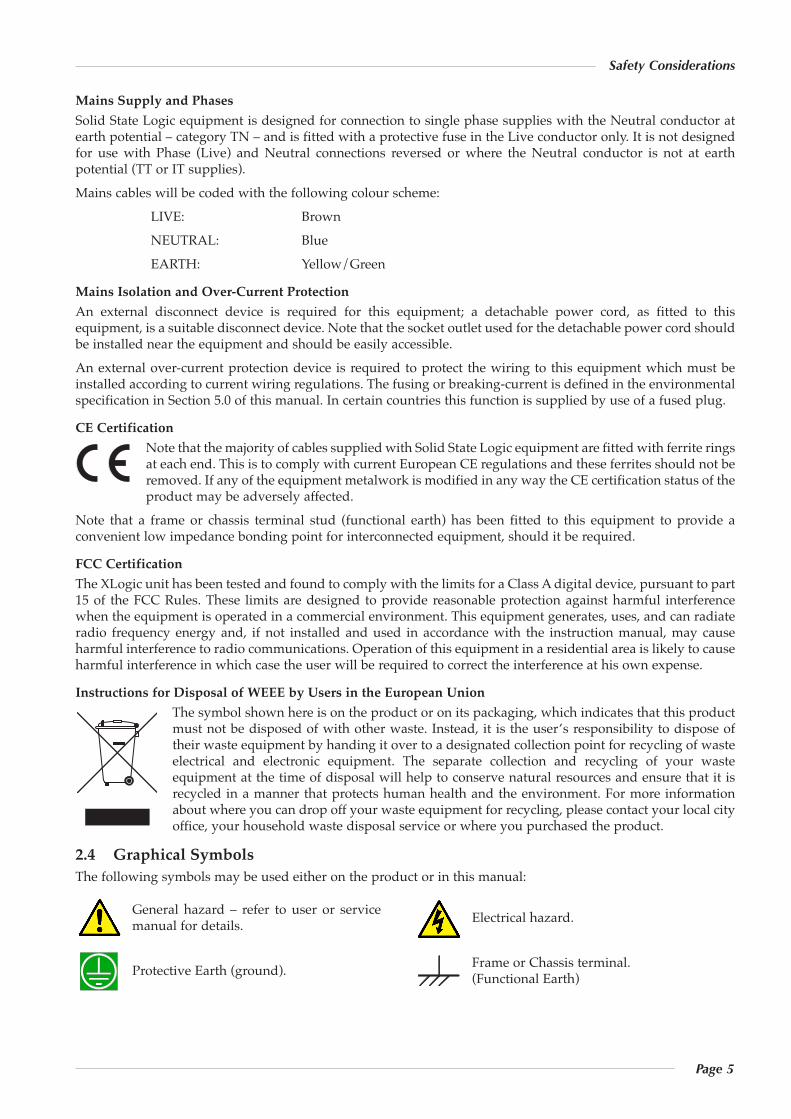
2.4 Graphical SymbolsThe following symbols may be used either on the product or in this manual:
Protective Earth (ground). Frame or Chassis terminal.(Functional Earth)
General hazard – refer to user or servicemanual for details. Electrical hazard.
AAAAAAAAAA

Page 6
X-Rack Owner’s Manual
3. X-Rack Installation
3.1 Assembling the X-RackThe X-Rack unit is normally shipped either as an empty rack (SSL Part No. 729935X1), a part filled (custom)rack or as a fully loaded unit; for example, a unit fitted with eight 729618X1 Dynamics modules (SSLPart No. 729935X2) – if you have purchased a fully loaded unit you should skip the rest of Section 3.1.In the case of empty or part filled racks, any empty module slots will be covered by blank panels whichwill need to be removed before fitting additional modules.
Note. Do not attempt to fit or remove modules with power applied. Always switch the rack off and remove the power cordprior to working on this unit. When fitting or removing modules, it is advisable to observe suitable ESD precautions.Take care when handling modules and blank panels; sharp corners may be present.
Modules are fitted from the front of the X-Rack, normally starting from the left hand end. Note that it isrecommended that any required blank panels (SSL Part No. 729618X2) are fitted prior to fitting modules.Each module plugs into the backplane; use the two 8mm M3 counter sunk screws supplied with themodule or blank to fix the item to the front of the rack – a 2mm AF hex key is supplied with the X-Rackunit. The rear connector panel or blank should be screwed to the rear of the case using the two 8mm M3button head screws supplied with the module. The end result should be a unit that is fully loaded withmodules and/or blank panels. For ease of fitting, do not tighten the screws until all modules and/or blankpanels have been fitted.
Note. To ensure peak operating performance, please ensure all rear panel fixing screws are securely tightened; warping onthe rear of the chassis may be observed – this is no cause for concern.
3.2 MountingThe X-Rack unit is designed to be rack mounted or free standing. It is 4RU (178mm/7 inches) high. Itsdepth is:
180 mm/7.2 inches255 mm/10.2 inches including connectors
The unit does not require rack shelves. A 1RU space should normally be provided above the unit.The unit is supplied fitted with both feet and rack ears. If the unit is to be rack mounted the feet should beremoved using the supplied 2.5 mm AF hex driver. The same driver can be used to remove the rack earsif the unit is to be free standing.
Feet and rack ears are fixed using M4 x 8mm screws. Do not replace them with longer screws as this may damage the rack electronics.
Page 7
3.3 Connection3.3.1 Power Connection
The X-Rack unit has an auto-sensing power supply that can operate on 100 – 230V without adjustment.The power connection is made via a standard IEC mains cord to an un-switched IEC mains socket on therear panel and a latching power switch is provided on the front panel of the unit.
3.3.2 Audio ConnectionGenerally, each module will have an input connector (normally a female XLR) and an output connector(normally a male XLR). Depending upon the type of module other connectors, such as key inputs, may bepresent also. Connect the module inputs to the insert sends of your console or to your workstation outputs.Connect the module outputs to the corresponding insert returns or to your workstation inputs.Once the unit is connected switch it on, then route a signal to each channel in turn and check that it isreturned to the correct input on your console or workstation.Some module input and output gains can be set to operate at a nominal level of +4dBu or –10dBV using aswitch on the connector panel. Select the appropriate level for the equipment you are connecting to. If indoubt either refer to the section of this manual specific to the particular module or experiment!
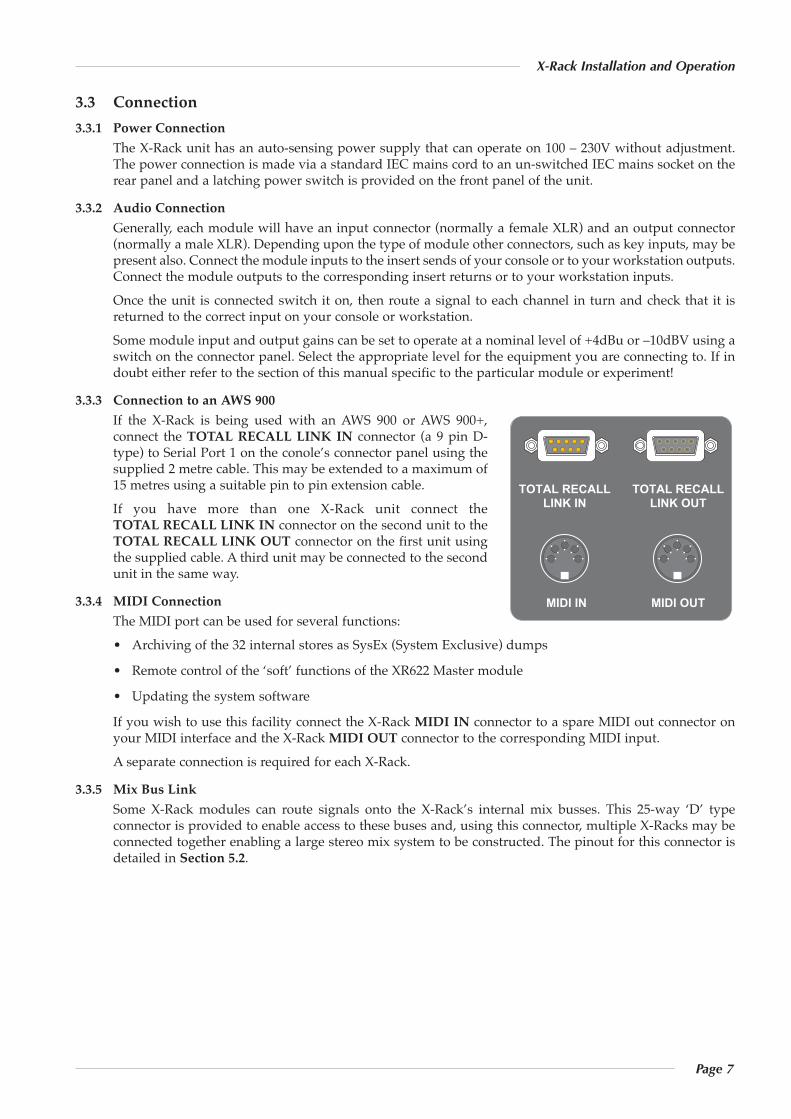
3.3.3 Connection to an AWS 900If the X-Rack is being used with an AWS 900 or AWS 900+,connect the TOTAL RECALL LINK IN connector (a 9 pin D-type) to Serial Port 1 on the conole’s connector panel using thesupplied 2 metre cable. This may be extended to a maximum of15 metres using a suitable pin to pin extension cable.If you have more than one X-Rack unit connect theTOTAL RECALL LINK IN connector on the second unit to theTOTAL RECALL LINK OUT connector on the first unit usingthe supplied cable. A third unit may be connected to the secondunit in the same way.
3.3.4 MIDI ConnectionThe MIDI port can be used for several functions:• Archiving of the 32 internal stores as SysEx (System Exclusive) dumps
• Remote control of the ‘soft’ functions of the XR622 Master module
• Updating the system software
If you wish to use this facility connect the X-Rack MIDI IN connector to a spare MIDI out connector onyour MIDI interface and the X-Rack MIDI OUT connector to the corresponding MIDI input.A separate connection is required for each X-Rack.
3.3.5 Mix Bus LinkSome X-Rack modules can route signals onto the X-Rack’s internal mix busses. This 25-way ‘D’ typeconnector is provided to enable access to these buses and, using this connector, multiple X-Racks may beconnected together enabling a large stereo mix system to be constructed. The pinout for this connector isdetailed in Section 5.2.
TOTAL RECALLLINK IN
MIDI IN MIDI OUT
TOTAL RECALLLINK OUT
X-Rack Installation and Operation
Page 8
X-Rack Owner’s Manual
4. Operation - Total Recall
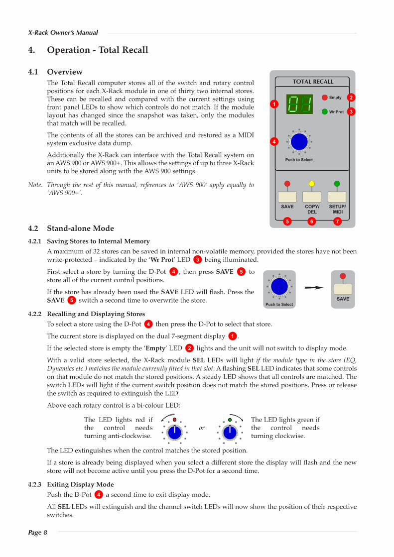
4.1 OverviewThe Total Recall computer stores all of the switch and rotary controlpositions for each X-Rack module in one of thirty two internal stores.These can be recalled and compared with the current settings usingfront panel LEDs to show which controls do not match. If the modulelayout has changed since the snapshot was taken, only the modulesthat match will be recalled.The contents of all the stores can be archived and restored as a MIDIsystem exclusive data dump.Additionally the X-Rack can interface with the Total Recall system onan AWS 900 or AWS 900+. This allows the settings of up to three X-Rackunits to be stored along with the AWS 900 settings.
Note. Through the rest of this manual, references to ‘AWS 900’ apply equally to‘AWS 900+’.
4.2 Stand-alone Mode 4.2.1 Saving Stores to Internal Memory
A maximum of 32 stores can be saved in internal non-volatile memory, provided the stores have not beenwrite-protected – indicated by the ‘Wr Prot’ LED being illuminated.First select a store by turning the D-Pot , then press SAVE tostore all of the current control positions.If the store has already been used the SAVE LED will flash. Press theSAVE switch a second time to overwrite the store.
4.2.2 Recalling and Displaying StoresTo select a store using the D-Pot then press the D-Pot to select that store.The current store is displayed on the dual 7-segment display .If the selected store is empty the ‘Empty’ LED lights and the unit will not switch to display mode.With a valid store selected, the X-Rack module SEL LEDs will light if the module type in the store (EQ,Dynamics etc.) matches the module currently fitted in that slot. A flashing SEL LED indicates that some controlson that module do not match the stored positions. A steady LED shows that all controls are matched. Theswitch LEDs will light if the current switch position does not match the stored positions. Press or releasethe switch as required to extinguish the LED.Above each rotary control is a bi-colour LED:
The LED extinguishes when the control matches the stored position.If a store is already being displayed when you select a different store the display will flash and the newstore will not become active until you press the D-Pot for a second time.
4.2.3 Exiting Display ModePush the D-Pot a second time to exit display mode.All SEL LEDs will extinguish and the channel switch LEDs will now show the position of their respectiveswitches.
4
The LED lights red ifthe control needsturning anti-clockwise.
orThe LED lights green ifthe control needsturning clockwise.
2
1
4
5
4 5
Push to Select SAVE
3
SETUP/ MIDI
SAVE
Push to Select
COPY/ DEL
TOTAL RECALL
Empty
Wr Prot
1
765
4
3
2
Page 9
X-Rack Installation and Operation
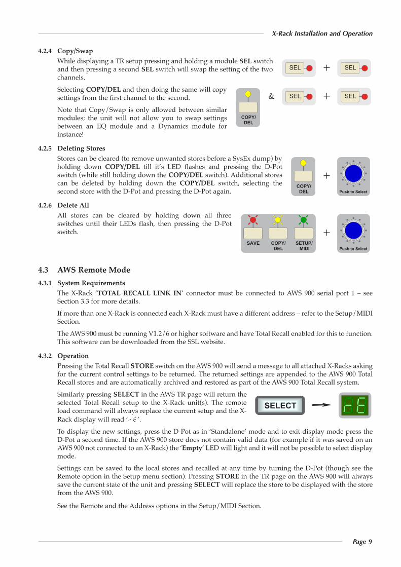
4.2.4 Copy/SwapWhile displaying a TR setup pressing and holding a module SEL switchand then pressing a second SEL switch will swap the setting of the twochannels. Selecting COPY/DEL and then doing the same will copysettings from the first channel to the second.Note that Copy/Swap is only allowed between similarmodules; the unit will not allow you to swap settingsbetween an EQ module and a Dynamics module forinstance!
4.2.5 Deleting StoresStores can be cleared (to remove unwanted stores before a SysEx dump) byholding down COPY/DEL till it’s LED flashes and pressing the D-Potswitch (while still holding down the COPY/DEL switch). Additional storescan be deleted by holding down the COPY/DEL switch, selecting thesecond store with the D-Pot and pressing the D-Pot again.
4.2.6 Delete AllAll stores can be cleared by holding down all threeswitches until their LEDs flash, then pressing the D-Potswitch.
4.3 AWS Remote Mode4.3.1 System Requirements
The X-Rack ‘TOTAL RECALL LINK IN’ connector must be connected to AWS 900 serial port 1 – seeSection 3.3 for more details.If more than one X-Rack is connected each X-Rack must have a different address – refer to the Setup/MIDISection.The AWS 900 must be running V1.2/6 or higher software and have Total Recall enabled for this to function.This software can be downloaded from the SSL website.
4.3.2 OperationPressing the Total Recall STORE switch on the AWS 900 will send a message to all attached X-Racks askingfor the current control settings to be returned. The returned settings are appended to the AWS 900 TotalRecall stores and are automatically archived and restored as part of the AWS 900 Total Recall system.Similarly pressing SELECT in the AWS TR page will return theselected Total Recall setup to the X-Rack unit(s). The remoteload command will always replace the current setup and the X-Rack display will read ‘re’.To display the new settings, press the D-Pot as in ‘Standalone’ mode and to exit display mode press the D-Pot a second time. If the AWS 900 store does not contain valid data (for example if it was saved on anAWS 900 not connected to an X-Rack) the ‘Empty’ LED will light and it will not be possible to select displaymode.Settings can be saved to the local stores and recalled at any time by turning the D-Pot (though see theRemote option in the Setup menu section). Pressing STORE in the TR page on the AWS 900 will alwayssave the current state of the unit and pressing SELECTwill replace the store to be displayed with the storefrom the AWS 900.
See the Remote and the Address options in the Setup/MIDI Section.
SELECT
SETUP/ MIDI
SAVE COPY/ DEL
+Push to Select
COPY/ DEL
+Push to Select
COPY/ DEL
& SEL + SEL
SEL + SEL
Page 10
X-Rack Owner’s Manual
4.4 Setup/MIDI Mode4.4.1 Overview
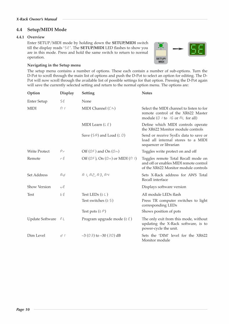
Enter SETUP/MIDI mode by holding down the SETUP/MIDI switchtill the display reads ‘5e’. The SETUP/MIDI LED flashes to show youare in this mode. Press and hold the same switch to return to normaloperation.
Navigating in the Setup menuThe setup menu contains a number of options. These each contain a number of sub-options. Turn the D-Pot to scroll through the main list of options and push the D-Pot to select an option for editing. The D-Pot will now scroll through the available list of possible settings for that option. Pressing the D-Pot againwill save the currently selected setting and return to the normal option menu. The options are:
Option Display Setting Notes
Enter Setup 5e None
MIDI m1 MIDI Channel (ck) Select the MIDI channel to listen to forremote control of the XR622 Mastermodule (01 to 16 or al for all)
MIDI Learn (le) Define which MIDI controls operatethe XR622 Monitor module controls
Save (sa) and Load (l0) Send or receive SysEx data to save orload all internal stores to a MIDIsequencer or librarian
Write Protect pr Off (0f) and On (0n) Toggles write protect on and off
Remote re Off (0f), On (0n) or MIDI (m1) Toggles remote Total Recall mode onand off or enables MIDI remote controlof the XR622 Monitor module controls
Set Address ad a1, a2, a3, a4 Sets X-Rack address for AWS TotalRecall interface
Show Version ve Displays software version
Test te Test LEDs (tl) All module LEDs flashTest switches (t5) Press TR computer switches to light
corresponding LEDsTest pots (tp) Shows position of pots
Update Software fl Program upgrade mode (te) The only exit from this mode, withoutupdating the X-Rack software, is topower-cycle the unit.
Dim Level d1 –3 (03) to –30 (30) dB Sets the ‘DIM’ level for the XR622Monitor module
SETUP/ MIDI
Page 11
X-Rack Installation and Operation
4.4.2 MIDI (m1)Under this menu it is possible to set the MIDI controls which can control parts of the X-Rack XR622 Mastermodule and also to save and load all internal stores to and from a MIDI sequencer or librarian as a SysExdump.
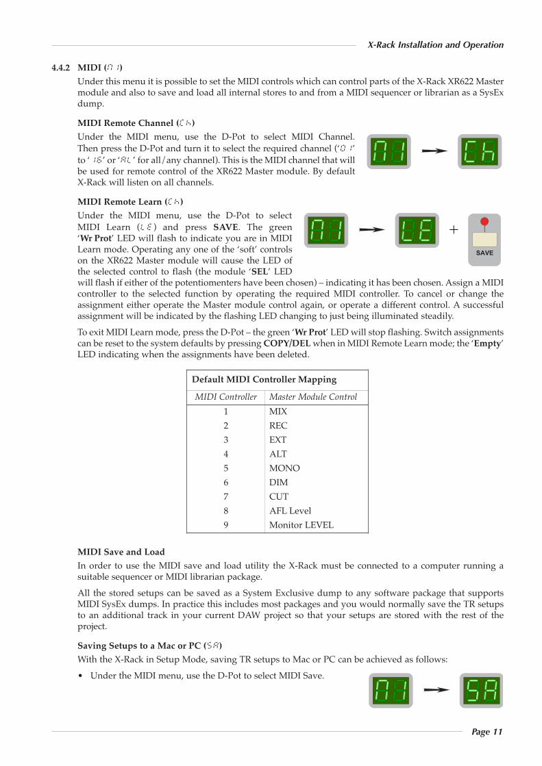
MIDI Remote Channel (ck)Under the MIDI menu, use the D-Pot to select MIDI Channel.Then press the D-Pot and turn it to select the required channel (‘01’to ‘16’ or ‘al’ for all/any channel). This is the MIDI channel that willbe used for remote control of the XR622 Master module. By default X-Rack will listen on all channels.
MIDI Remote Learn (ck)Under the MIDI menu, use the D-Pot to selectMIDI Learn (le) and press SAVE. The green‘Wr Prot’ LED will flash to indicate you are in MIDILearn mode. Operating any one of the ‘soft’ controlson the XR622 Master module will cause the LED ofthe selected control to flash (the module ‘SEL’ LEDwill flash if either of the potentiomenters have been chosen) – indicating it has been chosen. Assign a MIDIcontroller to the selected function by operating the required MIDI controller. To cancel or change theassignment either operate the Master module control again, or operate a different control. A successfulassignment will be indicated by the flashing LED changing to just being illuminated steadily.To exit MIDI Learn mode, press the D-Pot – the green ‘Wr Prot’ LED will stop flashing. Switch assignmentscan be reset to the system defaults by pressing COPY/DELwhen in MIDI Remote Learn mode; the ‘Empty’LED indicating when the assignments have been deleted.
MIDI Save and LoadIn order to use the MIDI save and load utility the X-Rack must be connected to a computer running asuitable sequencer or MIDI librarian package.All the stored setups can be saved as a System Exclusive dump to any software package that supportsMIDI SysEx dumps. In practice this includes most packages and you would normally save the TR setupsto an additional track in your current DAW project so that your setups are stored with the rest of theproject.
Saving Setups to a Mac or PC (sa)With the X-Rack in Setup Mode, saving TR setups to Mac or PC can be achieved as follows:• Under the MIDI menu, use the D-Pot to select MIDI Save.
Default MIDI Controller Mapping
MIDI Controller Master Module Control1 MIX2 REC3 EXT4 ALT5 MONO6 DIM7 CUT8 AFL Level9 Monitor LEVEL
+SAVE
Page 12
X-Rack Owner’s Manual
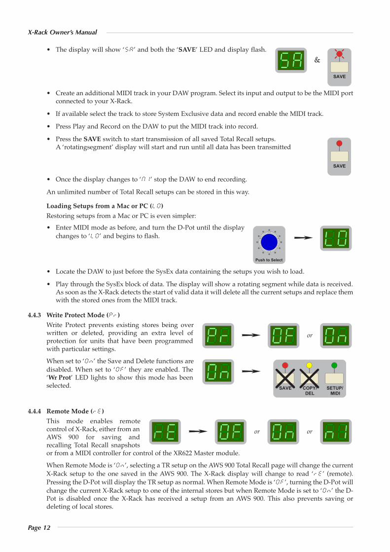
• The display will show ‘5a’ and both the ‘SAVE’ LED and display flash.
• Create an additional MIDI track in your DAW program. Select its input and output to be the MIDI portconnected to your X-Rack.
• If available select the track to store System Exclusive data and record enable the MIDI track.
• Press Play and Record on the DAW to put the MIDI track into record.
• Press the SAVE switch to start transmission of all saved Total Recall setups.A ‘rotatingsegment’ display will start and run until all data has been transmitted
• Once the display changes to ‘m1’ stop the DAW to end recording.
An unlimited number of Total Recall setups can be stored in this way.
Loading Setups from a Mac or PC (l0)Restoring setups from a Mac or PC is even simpler:• Enter MIDI mode as before, and turn the D-Pot until the display
changes to ‘l0’ and begins to flash.
• Locate the DAW to just before the SysEx data containing the setups you wish to load.
• Play through the SysEx block of data. The display will show a rotating segment while data is received.As soon as the X-Rack detects the start of valid data it will delete all the current setups and replace themwith the stored ones from the MIDI track.
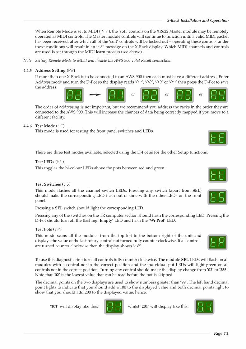
4.4.3 Write Protect Mode (pr)Write Protect prevents existing stores being overwritten or deleted, providing an extra level ofprotection for units that have been programmedwith particular settings.
When set to ‘0n’ the Save and Delete functions aredisabled. When set to ‘0f’ they are enabled. The‘Wr Prot’ LED lights to show this mode has beenselected.
4.4.4 Remote Mode (re)This mode enables remotecontrol of X-Rack, either from anAWS 900 for saving andrecalling Total Recall snapshotsor from a MIDI controller for control of the XR622 Master module.
When Remote Mode is ‘0n’, selecting a TR setup on the AWS 900 Total Recall page will change the currentX-Rack setup to the one saved in the AWS 900. The X-Rack display will change to read ‘re’ (remote).Pressing the D-Pot will display the TR setup as normal. When Remote Mode is ‘0f’, turning the D-Pot willchange the current X-Rack setup to one of the internal stores but when Remote Mode is set to ‘0n’ the D-Pot is disabled once the X-Rack has received a setup from an AWS 900. This also prevents saving ordeleting of local stores.
&
SAVE
SAVE
Push to Select
or or
SETUP/ MIDI
SAVE COPY/ DEL
or
Page 13
X-Rack Installation and Operation
When Remote Mode is set to MIDI (‘m1’), the ‘soft’ controls on the XR622 Master module may be remotelyoperated as MIDI controls. The Master module controls will continue to function until a valid MIDI packethas been received, after which all of the ‘soft’ controls will be locked out – operating these controls underthese conditions will result in an ‘re’ message on the X-Rack display. Which MIDI channels and controlsare used is set through the MIDI learn process (see above).
Note. Setting Remote Mode to MIDI will disable the AWS 900 Total Recall connection.
4.4.5 Address Setting (ad)If more than one X-Rack is to be connected to an AWS 900 then each must have a different address. EnterAddress mode and turn the D-Pot so the display reads ‘a1’, ‘a2’, ‘a3’ or ‘a4’ then press the D-Pot to savethe address:
The order of addressing is not important, but we recommend you address the racks in the order they areconnected to the AWS 900. This will increase the chances of data being correctly mapped if you move to adifferent facility.
4.4.6 Test Mode (te)This mode is used for testing the front panel switches and LEDs.
There are three test modes available, selected using the D-Pot as for the other Setup functions:
Test LEDs (tl)This toggles the bi-colour LEDs above the pots between red and green.
Test Switches (t5)This mode flashes all the channel switch LEDs. Pressing any switch (apart from SEL)should make the corresponding LED flash out of time with the other LEDs on the frontpanel.Pressing a SEL switch should light the corresponding LED.Pressing any of the switches on the TR computer section should flash the corresponding LED. Pressing theD-Pot should turn off the flashing ‘Empty’ LED and flash the ‘Wr Prot’ LED.
Test Pots (tp)This mode scans all the modules from the top left to the bottom right of the unit anddisplays the value of the last rotary control not turned fully counter clockwise. If all controlsare turned counter clockwise then the display shows ‘tp’.
To use this diagnostic first turn all controls fully counter clockwise. The module SEL LEDs will flash on allmodules with a control not in the correct position and the individual pot LEDs will light green on allcontrols not in the correct position. Turning any control should make the display change from ’02’ to ‘255’.Note that ‘02’ is the lowest value that can be read before the pot is skipped.The decimal points on the two displays are used to show numbers greater than ‘99’. The left hand decimalpoint lights to indicate that you should add a 100 to the displayed value and both decimal points light toshow that you should add 200 to the displayed value, hence:
‘101’ will display like this: whilst ‘201’ will display like this:
ororor
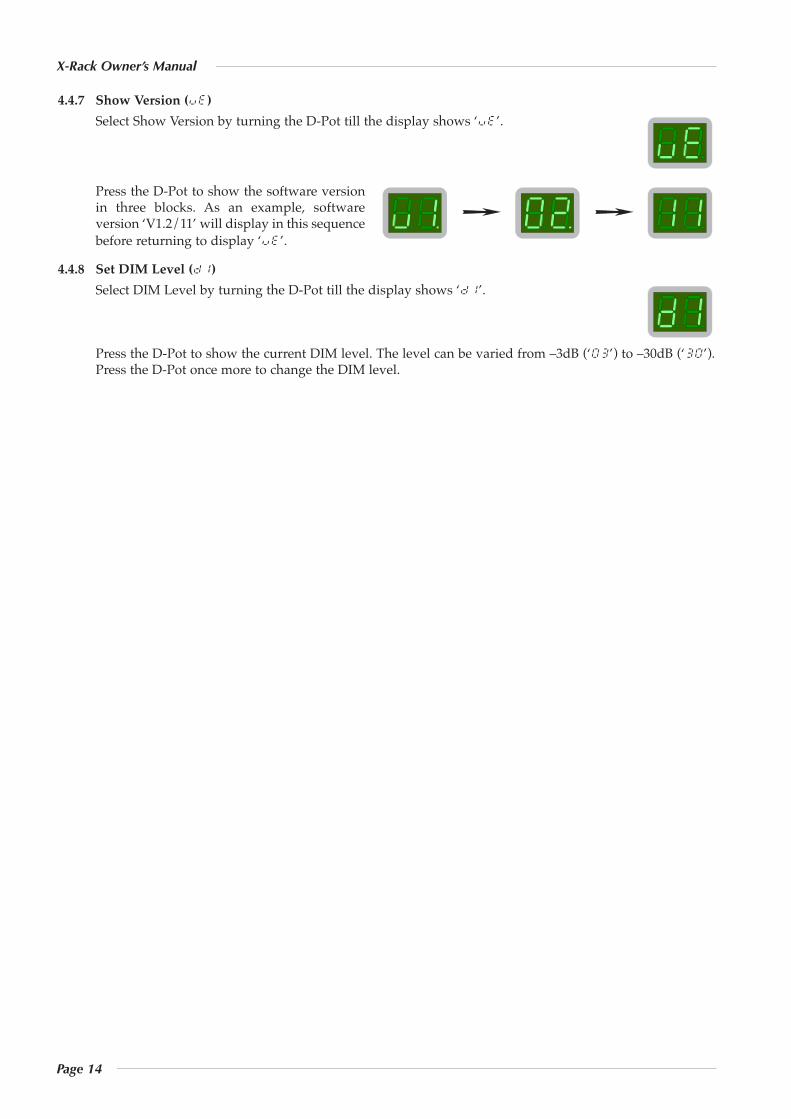
4.4.7 Show Version (ve)Select Show Version by turning the D-Pot till the display shows ‘ve’.
Press the D-Pot to show the software versionin three blocks. As an example, softwareversion ‘V1.2/11’ will display in this sequencebefore returning to display ‘ve’.
4.4.8 Set DIM Level (d1)Select DIM Level by turning the D-Pot till the display shows ‘d1’.
Press the D-Pot to show the current DIM level. The level can be varied from –3dB (‘03’) to –30dB (‘30’).Press the D-Pot once more to change the DIM level.
Page 14
X-Rack Owner’s Manual
Page 15
X-Rack Installation and Operation
4.5 Software Download and InstallationSoftware to upgrade your X-Rack unit can be downloaded from the SSL website (http://www.solid-state-logic.com/plus/utilities.html). To access this page will you will need to be registered with us and logged into the website.The X-Rack software is packaged as a 50kB (approximately) Java archive file, the format of which is compatiblewith both PC and Macintosh (OS X only) platforms. Some users may need to install additional files on their computerbefore continuing – see System Requirements overleaf.
Once the software package has been downloaded, it will need to be moved onto a Mac or PC that is connectedto the X-Rack via MIDI after which you will be ready to install the new software. The following steps detail thisprocess:1. Ensure that the X-Rack is turned on and connected to a MIDI port on your PC/Mac.
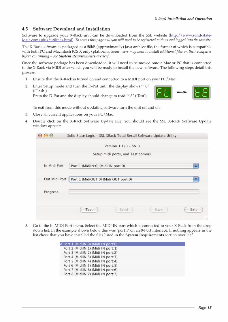
2. Enter Setup mode and turn the D-Pot until the display shows ‘fl’(‘Flash’).Press the D-Pot and the display should change to read ‘te’ (‘Test’).
To exit from this mode without updating software turn the unit off and on.3. Close all current applications on your PC/Mac.4. Double click on the X-Rack Software Update File. You should see the SSL X-Rack Software Update
window appear:
5. Go to the In MIDI Port menu. Select the MIDI IN port which is connected to your X-Rack from the dropdown list. In the example shown below this was ‘port 1’ on an 8-Port interface. If nothing appears in thelist check that you have installed the files listed in the System Requirements section over leaf.
Page 16
X-Rack Owner’s Manual
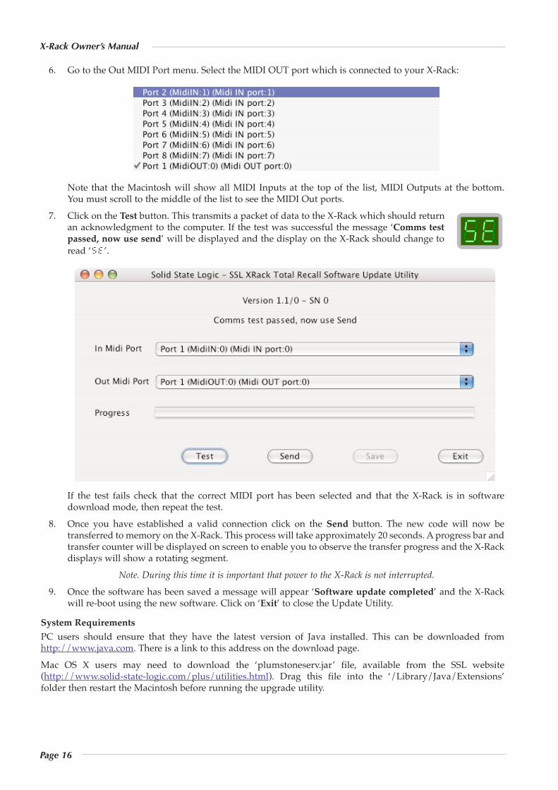
6. Go to the Out MIDI Port menu. Select the MIDI OUT port which is connected to your X-Rack:
Note that the Macintosh will show all MIDI Inputs at the top of the list, MIDI Outputs at the bottom.You must scroll to the middle of the list to see the MIDI Out ports.
7. Click on the Test button. This transmits a packet of data to the X-Rack which should returnan acknowledgment to the computer. If the test was successful the message ‘Comms testpassed, now use send’ will be displayed and the display on the X-Rack should change toread ‘se’.
If the test fails check that the correct MIDI port has been selected and that the X-Rack is in softwaredownload mode, then repeat the test.
8. Once you have established a valid connection click on the Send button. The new code will now betransferred to memory on the X-Rack. This process will take approximately 20 seconds. A progress bar andtransfer counter will be displayed on screen to enable you to observe the transfer progress and the X-Rackdisplays will show a rotating segment.
Note. During this time it is important that power to the X-Rack is not interrupted.
9. Once the software has been saved a message will appear ‘Software update completed’ and the X-Rackwill re-boot using the new software. Click on ‘Exit’ to close the Update Utility.
System RequirementsPC users should ensure that they have the latest version of Java installed. This can be downloaded fromhttp://www.java.com. There is a link to this address on the download page.Mac OS X users may need to download the ‘plumstoneserv.jar’ file, available from the SSL website(http://www.solid-state-logic.com/plus/utilities.html). Drag this file into the ‘/Library/Java/Extensions’folder then restart the Macintosh before running the upgrade utility.
Page 17
X-Rack Installation and Operation
5. Miscellaneous
5.1 X-Rack Internal Links and Fuses5.1.1 Fuses (Mains Inlet)
The power supply module is internally fused. In the event of this fuse failing the entire unit should bereturned to your nearest SSL Service agent.
5.1.2 Internal FusesThe internal power rail fuses will automatically reset once the fault condition has been removed andshould not need to be replaced.
5.1.3 LinksThere are no user settable links.
5.2 X-Rack Connector Details
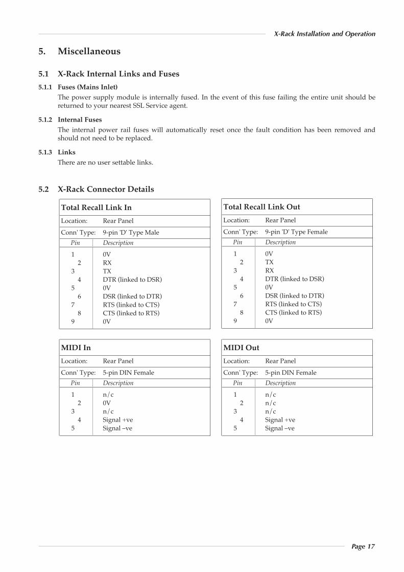
MIDI InLocation: Rear PanelConn' Type: 5-pin DIN Female Pin Description
1 n/c2 0V
3 n/c4 Signal +ve
5 Signal –ve
MIDI OutLocation: Rear PanelConn' Type: 5-pin DIN Female Pin Description
1 n/c2 n/c
3 n/c4 Signal +ve
5 Signal –ve
Total Recall Link InLocation: Rear PanelConn' Type: 9-pin 'D' Type Male Pin Description
1 0V2 RX
3 TX4 DTR (linked to DSR)
5 0V6 DSR (linked to DTR)
7 RTS (linked to CTS)8 CTS (linked to RTS)
9 0V
Total Recall Link OutLocation: Rear PanelConn' Type: 9-pin 'D' Type Female Pin Description
1 0V2 TX
3 RX4 DTR (linked to DSR)
5 0V6 DSR (linked to DTR)
7 RTS (linked to CTS)8 CTS (linked to RTS)
9 0V
Page 18
X-Rack Owner’s Manual
X-Rack Connector Details (cont.)
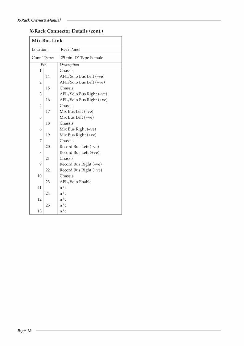
Mix Bus LinkLocation: Rear Panel
Conn’ Type: 25-pin ‘D’ Type FemalePin Description1 Chassis
14 AFL/Solo Bus Left (–ve)2 AFL/Solo Bus Left (+ve)
15 Chassis3 AFL/Solo Bus Right (–ve)
16 AFL/Solo Bus Right (+ve)4 Chassis
17 Mix Bus Left (–ve)5 Mix Bus Left (+ve)
18 Chassis6 Mix Bus Right (–ve)
19 Mix Bus Right (+ve)7 Chassis
20 Record Bus Left (–ve)8 Record Bus Left (+ve)
21 Chassis9 Record Bus Right (–ve)
22 Record Bus Right (+ve)10 Chassis
23 AFL/Solo Enable11 n/c
24 n/c12 n/c
25 n/c13 n/c
Page 19
X-Rack Installation and Operation
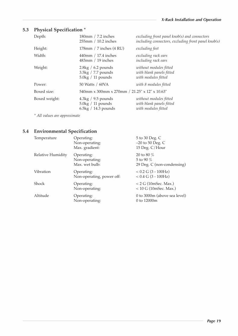
5.3 Physical Specification *Depth: 180mm / 7.2 inches excluding front panel knob(s) and connectors
255mm / 10.2 inches including connectors, excluding front panel knob(s)
Height: 178mm / 7 inches (4 RU) excluding feet
Width: 440mm / 17.4 inches excluding rack ears483mm / 19 inches including rack ears
Weight: 2.8kg / 6.2 pounds without modules fitted3.5kg / 7.7 pounds with blank panels fitted5.0kg / 11 pounds with modules fitted
Power: 50 Watts / 60VA with 8 modules fitted
Boxed size: 540mm x 300mm x 270mm / 21.25" x 12" x 10.63"Boxed weight: 4.3kg / 9.5 pounds without modules fitted
5.0kg / 11 pounds with blank panels fitted6.5kg / 14.3 pounds with modules fitted
* All values are approximate
5.4 Environmental SpecificationTemperature Operating: 5 to 30 Deg. C
Non-operating: –20 to 50 Deg. CMax. gradient: 15 Deg. C/Hour
Relative Humidity Operating: 20 to 80 %Non-operating: 5 to 90 %Max. wet bulb: 29 Deg. C (non-condensing)
Vibration Operating: < 0.2 G (3 - 100Hz)Non-operating, power off: < 0.4 G (3 - 100Hz)
Shock Operating: < 2 G (10mSec. Max.)Non-operating: < 10 G (10mSec. Max.)
Altitude Operating: 0 to 3000m (above sea level)Non-operating: 0 to 12000m

Page 20
X-Rack Owner’s Manual
Notes
Page A-1
X-Rack Mic Amp Module
A. The Mic Amp Module
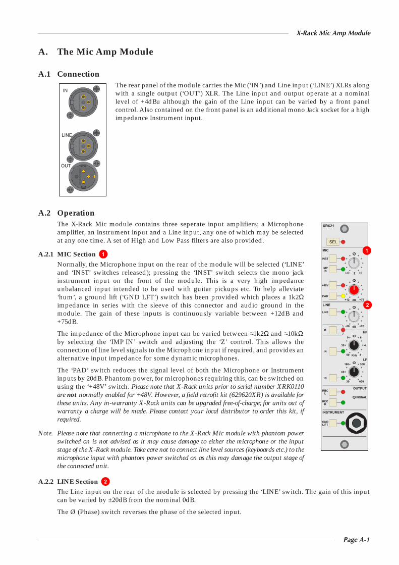
A.1 ConnectionThe rear panel of the module carries the Mic (‘IN’) and Line input (‘LINE’) XLRs alongwith a single output (‘OUT’) XLR. The Line input and output operate at a nominallevel of +4dBu although the gain of the Line input can be varied by a front panelcontrol. Also contained on the front panel is an additional mono Jack socket for a highimpedance Instrument input.
A.2 OperationThe X-Rack Mic module contains three seperate input amplifiers; a Microphoneamplifier, an Instrument input and a Line input, any one of which may be selectedat any one time. A set of High and Low Pass filters are also provided.
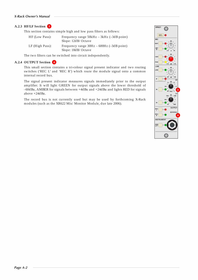
A.2.1 MIC Section
Normally, the Microphone input on the rear of the module will be selected (‘LINE’and ‘INST’ switches released); pressing the ‘INST’ switch selects the mono jackinstrument input on the front of the module. This is a very high impedanceunbalanced input intended to be used with guitar pickups etc. To help alleviate‘hum’, a ground lift (‘GND LFT’) switch has been provided which places a 1k2Ωimpedance in series with the sleeve of this connector and audio ground in themodule. The gain of these inputs is continuously variable between +12dB and+75dB.
The impedance of the Microphone input can be varied between ≈1k2Ω and ≈10kΩby selecting the ‘IMP IN’ switch and adjusting the ‘Z’ control. This allows theconnection of line level signals to the Microphone input if required, and provides analternative input impedance for some dynamic microphones.
The ‘PAD’ switch reduces the signal level of both the Microphone or Instrumentinputs by 20dB. Phantom power, for microphones requiring this, can be switched onusing the ‘+48V’ switch. Please note that X-Rack units prior to serial number XRK0110are not normally enabled for +48V. However, a field retrofit kit (629620XR) is available forthese units. Any in-warranty X-Rack units can be upgraded free-of-charge; for units out ofwarranty a charge will be made. Please contact your local distributor to order this kit, ifrequired.
Note. Please note that connecting a microphone to the X-Rack Mic module with phantom powerswitched on is not advised as it may cause damage to either the microphone or the inputstage of the X-Rack module. Take care not to connect line level sources (keyboards etc.) to themicrophone input with phantom power switched on as this may damage the output stage ofthe connected unit.
A.2.2 LINE Section
The Line input on the rear of the module is selected by pressing the ‘LINE’ switch. The gain of this inputcan be varied by ±20dB from the nominal 0dB.
The Ø (Phase) switch reverses the phase of the selected input.
2
1
SEL
XR621
MIC
INST
IMP
+48V
PAD
LINE
LINE
Ø HF
IN
IN
IN
REC
REC
L
R
GND LIFT
INSTRUMENT
OUTPUT
SIGNAL
LF
Z LO HI
dB +75 +12
+20 -20 dB
KHz
9 6
3 50
30 4
30 600
60
160 300
IN
OUT
LINE
1
2
Page A-2
X-Rack Owner’s Manual
A.2.3 HF/LF Section
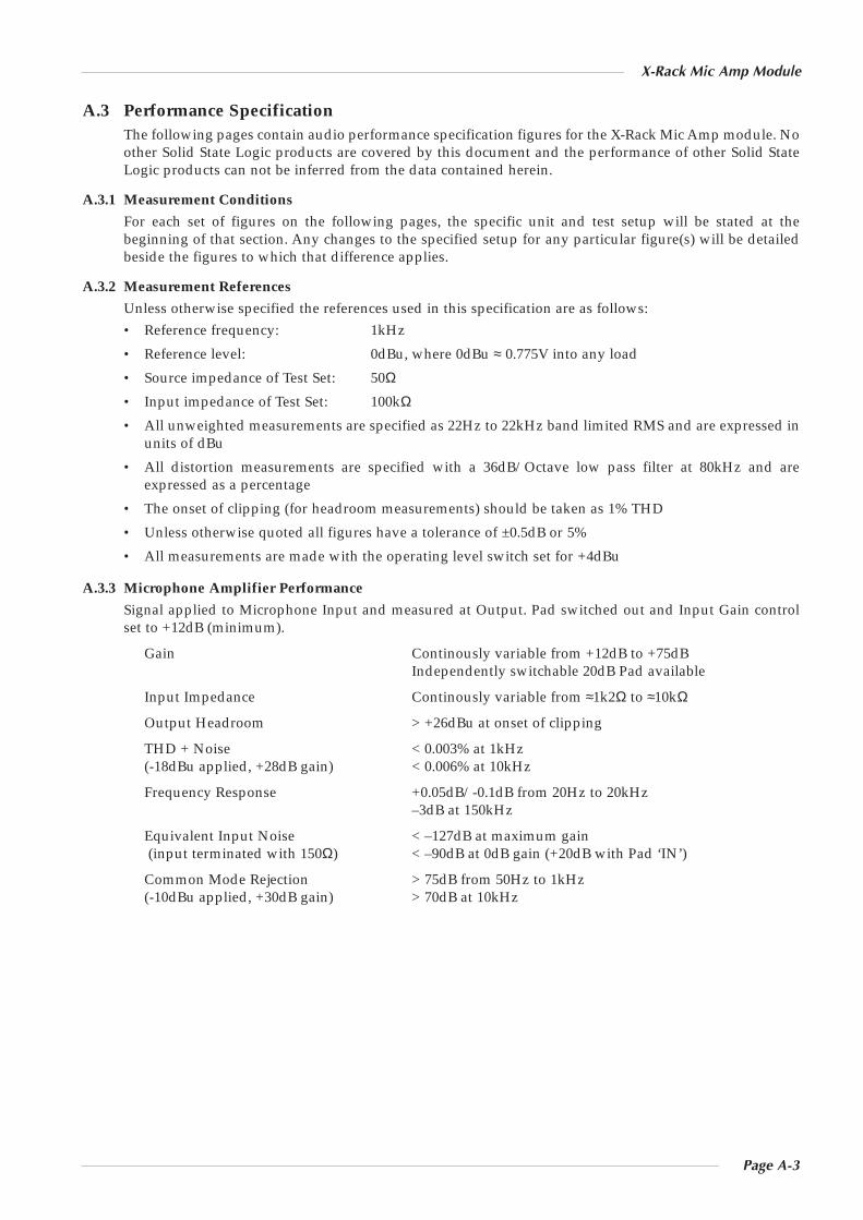
This section contains simple high and low pass filters as follows:
HF (Low Pass): Frequency range 50kHz – 3kHz (–3dB point)Slope: 12dB/Octave
LF (High Pass): Frequency range 30Hz – 600Hz (–3dB point)Slope: 18dB/Octave
The two filters can be switched into circuit independently.
A.2.4 OUTPUT Section
This small section contains a tri-colour signal present indicator and two routingswitches (‘REC L’ and ‘REC R’) which route the module signal onto a commoninternal record bus.
The signal present indicator measures signals immediately prior to the outputamplifier. It will light GREEN for output signals above the lower threshold of–60dBu, AMBER for signals between +4dBu and +24dBu and lights RED for signalsabove +24dBu.
The record bus is not currently used but may be used by forthcoming X-Rackmodules (such as the XR622 Mix/Monitor Module, due late 2006).
4
SEL
XR621
MIC
INST
IMP
+48V
PAD
LINE
LINE
Ø HF
IN
IN
IN
REC
REC
L
R
GND LIFT
INSTRUMENT
OUTPUT
SIGNAL
LF
Z LO HI
dB +75 +12
+20 -20 dB
KHz
9 6
3 50
30 4
30 600
60
160 300
3
3
4
Page A-3
X-Rack Mic Amp Module
A.3 Performance SpecificationThe following pages contain audio performance specification figures for the X-Rack Mic Amp module. Noother Solid State Logic products are covered by this document and the performance of other Solid StateLogic products can not be inferred from the data contained herein.
A.3.1 Measurement Conditions
For each set of figures on the following pages, the specific unit and test setup will be stated at thebeginning of that section. Any changes to the specified setup for any particular figure(s) will be detailedbeside the figures to which that difference applies.
A.3.2 Measurement References
Unless otherwise specified the references used in this specification are as follows:• Reference frequency: 1kHz
• Reference level: 0dBu, where 0dBu ≈ 0.775V into any load
• Source impedance of Test Set: 50Ω
• Input impedance of Test Set: 100kΩ
• All unweighted measurements are specified as 22Hz to 22kHz band limited RMS and are expressed inunits of dBu
• All distortion measurements are specified with a 36dB/Octave low pass filter at 80kHz and areexpressed as a percentage
• The onset of clipping (for headroom measurements) should be taken as 1% THD
• Unless otherwise quoted all figures have a tolerance of ±0.5dB or 5%
• All measurements are made with the operating level switch set for +4dBu
A.3.3 Microphone Amplifier Performance
Signal applied to Microphone Input and measured at Output. Pad switched out and Input Gain controlset to +12dB (minimum).
Gain Continously variable from +12dB to +75dBIndependently switchable 20dB Pad available
Input Impedance Continously variable from ≈1k2Ω to ≈10kΩ
Output Headroom > +26dBu at onset of clipping
THD + Noise < 0.003% at 1kHz(-18dBu applied, +28dB gain) < 0.006% at 10kHz
Frequency Response +0.05dB/-0.1dB from 20Hz to 20kHz–3dB at 150kHz
Equivalent Input Noise < –127dB at maximum gain(input terminated with 150Ω) < –90dB at 0dB gain (+20dB with Pad ‘IN’)
Common Mode Rejection > 75dB from 50Hz to 1kHz(-10dBu applied, +30dB gain) > 70dB at 10kHz

Page A-4
X-Rack Owner’s Manual
A.3.4 Instrument Input Performance
Un-balanced signal applied to Instrument Input and measured at Output. Pad switched out and InputGain control set to +12dB (minimum).
Gain Continously variable from +12dB to +75dBIndependently switchable 18dB Pad available
Input Impedance 1MΩ
Output Headroom > +26dBu at onset of clipping
THD + Noise < 0.03% at 1kHz(-18dBu applied, +28dB gain) < 0.05% at 10kHz
Frequency Response +0.05dB/-0.1dB from 20Hz to 20kHz–3dB at 150kHz
Equivalent Input Noise < –82dB at +12dB (minimum) gain(Input terminated with 150Ω) < –88dB at +28dB gain (mid’ position)
A.3.5 Line Input Performance
Signal applied to Line Input and measured at Output. Input Gain control set to 0dB (indent).
Gain Continuously variable from –20dB to +20dB
Input Impedance > 10kΩ
THD + Noise < 0.005% from 20Hz to 20kHz(+24dBu applied, 0dB gain)
Frequency Response ±0.1dB from 20Hz to 20kHz–3dB at 150kHz
Equivalent Input Noise < –90dB(Input terminated with 150Ω)
Page A-5
X-Rack Mic Amp Module
A.4 Calibration InformationThe X-Rack Mic Amp module is factory calibrated and should only need calibration if a potentiometer orother component has been replaced or if it is suspected that there is a problem with calibration.
In each of the following instructions it is assumed that the lid of the X-Rack has been removed and thatpower has been applied. It is also assumed that unless otherwise specified, all switches are released andall front panel potentiometers are at unity or minimum position as appropriate. The required accuracy foreach adjustment will be specified along with the target value. All level and distortion measurementsshould be made with audio-band 20Hz to 20kHz filters unless otherwise specified.
All presets are accessible from the top of the unit.
A.4.1 Microphone Input
Equipment Required: Calibrated audio oscillator and audio level meter
Test Signal: 50Hz sinewave @ –12dBu, common mode
Input and Output: Oscillator to Mic Input and Output to the audio level meter
Unit Setup: Set the Mic Gain to ‘36dB’ (mid-position)
CMRR Trim
Adjustment: Adjust VR7 (CMRR) for minimum level (normally < –40dBu)
A.4.2 Line Input
Equipment Required: Calibrated audio oscillator and audio level meter
Test Signal: 1kHz sinewave @ 0dBu
Input and Output: Oscillator to Line Input and Output to the audio level meter
Unit Setup: Set the Line Gain to indent (0dB) and select ‘LINE’
Level Trim
Adjustment: 1. Adjust VR6 (0dB) for 0dBu ±0.05dB.
A.4.3 Output Balance
Equipment Required: Calibrated audio oscillator, audio level meter and a ‘balance’ adaptor (seebelow)
Test Signal: 1kHz sine wave at +24dBu
Input and Output: Oscillator to Line Input and Output to the audio level meter via the‘balance’ adaptor
Unit Setup: Set the Line Gain to indent (0dB) and select ‘LINE’
Adjustment: Adjust VR8 (BAL) for minimum level (< 55dBr)
A.4.4 ‘Balance’ Adaptor
For the output balance adjustment, a ‘balance’adaptor such as that illustrated here will berequired. This adaptor consists of a pair of closetolerance resistors in an in-line cable and isused to sum together a balanced output inorder to correctly adjust the level balance of themeasured output; perfect balance should resultin complete signal cancellation.
5K01**
5K01**
2
3
1
2
3
1
0V
+
–
0V
+
–
To measuring equipment
From unit under test
1
2 1
Resistor tolerance should ideally be 0.01%Absolute level measured will depend upon the inputimpedence of the measuring equipment.
1.2.
Note
Page A-6
X-Rack Owner’s Manual
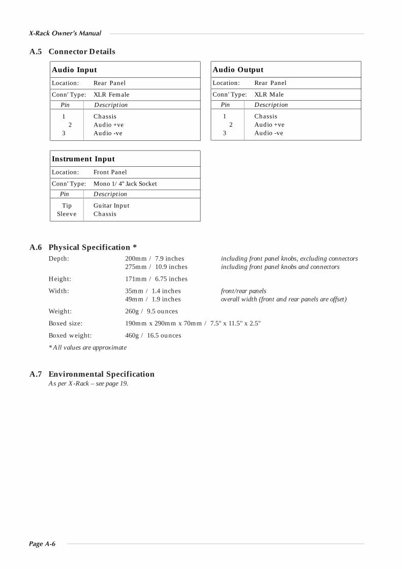
A.5 Connector Details
A.6 Physical Specification *Depth: 200mm / 7.9 inches including front panel knobs, excluding connectors
275mm / 10.9 inches including front panel knobs and connectors
Height: 171mm / 6.75 inches
Width: 35mm / 1.4 inches front/rear panels49mm / 1.9 inches overall width (front and rear panels are offset)
Weight: 260g / 9.5 ounces
Boxed size: 190mm x 290mm x 70mm / 7.5" x 11.5" x 2.5"
Boxed weight: 460g / 16.5 ounces
* All values are approximate
A.7 Environmental SpecificationAs per X-Rack – see page 19.
Instrument Input
Location: Front Panel
Conn' Type: Mono 1/4" Jack Socket
Pin Description
Tip Guitar InputSleeve Chassis
Audio Output
Location: Rear Panel
Conn' Type: XLR Male
Pin Description
1 Chassis2 Audio +ve
3 Audio -ve
Audio Input
Location: Rear Panel
Conn' Type: XLR Female
Pin Description
1 Chassis2 Audio +ve
3 Audio -ve

Page B-1
X-Rack EQ Module
B. The EQ Module
B.1 ConnectionThe module input and output gains can be set to operate at a nominal level of either+4dBu or –10dBV, using a switch on the connector panel. To select the appropriatelevel for the equipment you are connecting to, please check the operating manual foryour mixer or DAW. The switch should be released for +4dBu operation: push it in for–10dBV operation.
B.2 OperationThe EQ module is a 4-band equaliser that can be switched between two differentsets of curves, one based on the latest version of the classic SSL E Series EQ and theother based on SSL’s G Series EQ.
The G-EQ button switches the EQ from ‘E’ operation to ‘G’ operation.
The IN button switches the entire section in and out of circuit.
B.2.1 Frequency Sections
The different frequency sections are as follows:
HF Section: Frequency range 1.5kHz – 22kHzGain ±20dB
LF Section: Frequency range 40Hz – 600HzGain ±16.5dB
The HF and LF sections provide shelving equalisers with variable turnoverfrequency and a gentle slope. Selecting the ‘G-EQ’ button provides a slightly steeperslope for both sections with a degree of overshoot/undershoot (depending onwhether you are boosting or cutting) below the selected HF frequency (or above theselected LF frequency). Selecting ‘ ’ (‘Bell’) in either mode switches the equaliserto a peaking curve.
HMF Section: Centre frequency 600Hz – 7kHzGain ±20dBContinuously variable Q (0.7 – 2.5)
LMF Section: Centre frequency 200Hz to 2.5kHzGain ±20dBContinuously variable Q (0.7 – 2.5)
Normally, at any Q setting, the bandwidth of the HMF and LMF sections varies withgain, whereby an increase in boost or cut increases the selectivity of the EQ. Thistype of EQ can sound effective when used at moderate settings; the gentle Q curve lends itself to theapplication of overall EQ on combined sources and subtle corrective adjustments to instruments andvocals.
When the EQ is switched to ‘G-EQ’ operation, at any given Q setting the bandwidth of the HMF and LMFsections varies with gain such that an increase in boost or cut increases the selectivity of the EQ. This typeof EQ can sound effective when used at moderate settings; the gentle Q curve lends itself to the applicationof overall EQ on combined sources and subtle corrective adjustments to instruments and vocals.
2
1
SEL
XR625
HF dB
HMF
LMF
dB
dB
LF dB
Q
Q
- +
- +
- +
- +
IN
G-EQ
KHz
KHz
22 1.5
10 5
2 15
7 .6
3 2
1 5
Hz
KHz
2.0 .2
1.0 .6
.3 1.6
600 40
220
60
OUT
IN
+4dBu-10dBV
1
2

Page B-2
X-Rack Owner’s Manual

Page B-3
X-Rack EQ Module
B.3 Performance SpecificationThe following pages contain audio performance specification figures for the X-Rack EQ Module. No otherSolid State Logic products are covered by this document and the performance of other Solid State Logicproducts can not be inferred from the data contained herein.
B.3.1 Measurement Conditions
For each set of figures on the following pages, the specific unit and test setup will be stated at thebeginning of that section. Any changes to the specified setup for any particular figure(s) will be detailedbeside the figures to which that difference applies.
B.3.2 Measurement References
Unless otherwise specified the references used in this specification are as follows:• Reference frequency: 1kHz
• Reference level: 0dBu, where 0dBu ≈ 0.775V into any load
• Source impedance of Test Set: 50Ω
• Input impedance of Test Set: 100kΩ
• All unweighted measurements are specified as 22Hz to 22kHz band limited RMS and are expressed inunits of dBu
• All distortion measurements are specified with a 36dB/Octave low pass filter at 80kHz and areexpressed as a percentage
• The onset of clipping (for headroom measurements) should be taken as 1% THD
• Unless otherwise quoted all figures have a tolerance of ±0.5dB or 5%
• All measurements are made with the operating level switch set for +4dBu
B.3.3 Performance
Signal applied to Input and measured at Output. EQ switched In. All EQ controls set centre as appropriate.
THD + N < 0.005% at +20dBu 1kHz< 0.007% at +20dBu 10kHz
Frequency Response ±0.5dB from 20Hz to 20kHz–3dB at 200kHz
Output Headroom > +26dBu at onset of clipping
Noise < –83dBu (+4dBu operating level)< –92dBu (–10dBV operating level)
B.3.4 Curves
Each channel contains a four band equaliser that can be switched between two different sets of curves, onebased on the latest version of the classic SSL E Series EQ and the other based on SSL’s G Series EQ. Highand low pass filters are also available.
HF Band controls:
Frequency Variable from 1.5kHz to 22kHz
Gain Variable between ±20dB
‘Q’ 2.5 (on ‘ ’ setting)
HMF Band controls:
Frequency Variable from 600Hz to 7kHz
Gain Variable by > ±20dB
‘Q’ Variable from 0.5 to 2.5 (may also vary with gain)
Page B-4
X-Rack Owner’s Manual
LMF Band controls:
Frequency Variable from 200Hz to 2.5kHz
Gain Variable by > ±20dB
‘Q’ Variable from 0.5 to 2.5 (may also vary with gain)
LF Band controls:
Frequency Variable from 40Hz to 600Hz
Gain Variable between ±16.5dB
‘Q’ 2.5 (on ‘ ’ setting)
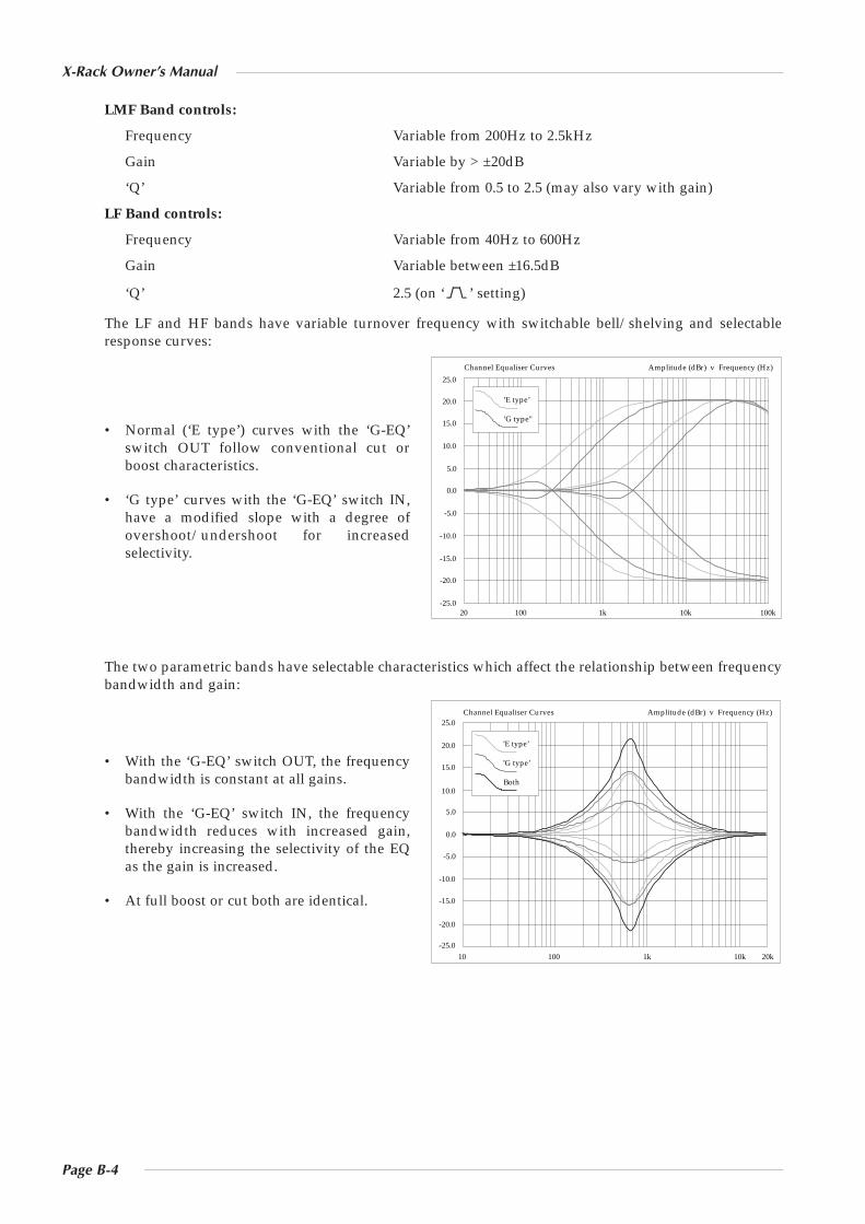
The LF and HF bands have variable turnover frequency with switchable bell/shelving and selectableresponse curves:
• Normal (‘E type’) curves with the ‘G-EQ’switch OUT follow conventional cut orboost characteristics.
• ‘G type’ curves with the ‘G-EQ’ switch IN,have a modified slope with a degree ofovershoot/undershoot for increasedselectivity.
The two parametric bands have selectable characteristics which affect the relationship between frequencybandwidth and gain:
• With the ‘G-EQ’ switch OUT, the frequencybandwidth is constant at all gains.
• With the ‘G-EQ’ switch IN, the frequencybandwidth reduces with increased gain,thereby increasing the selectivity of the EQas the gain is increased.
• At full boost or cut both are identical.
10 100 1k 10k 20k-25.0
-20.0
-15.0
-10.0
-5.0
0.0
5.0
10.0
15.0
20.0
25.0Amplitude (dBr) v Frequency (Hz)Channel Equaliser Curves
’G type’
’E type’
Both
0.0
25.0
-25.020 100 1k 10k 100k
-20.0
-15.0
-10.0
-5.0
5.0
10.0
15.0
20.0
Amplitude (dBr) v Frequency (Hz)Channel Equaliser Curves
’G type"
’E type’
Page B-5
X-Rack EQ Module
B.4 Calibration InformationThe X-Rack EQ module is factory calibrated and should only need calibration if a potentiometer or othercomponent has been replaced or if it is suspected that there is a problem with calibration.
In each of the following instructions it is assumed that the lid of the X-Rack has been removed and thatpower has been applied. It is also assumed that unless otherwise specified, all switches are released andall front panel potentiometers are at unity or minimum position as appropriate. The required accuracy foreach adjustment will be specified along with the target value. All level and distortion measurementsshould be made with audio-band 20Hz to 20kHz filters unless otherwise specified.
All presets are accessible from the top of the unit.
Note. The unit should be allowed to warm up with power applied for at least 15 minutes prior to making any adjustments.
B.4.1 EQ Alignment
Equipment Required: Calibrated audio oscillator and audio level meter
Test Signal: Sine wave @ –6dBu, frequencies as specified below
Input and Output: Oscillator to Input, Output to the audio level meter
Unit Setup: 1. Switch the EQ IN and release all other EQ switches.
2. Release the +4dBu/–10dBV switch on the rear panel.
3. Set all of the Q and Frequency controls fully anti-clockwise and all Gaincontrols to their centre indent.
HF EQ - Maximum Gain
Adjustment: 1. Set HF Gain to maximum and select HF . Set the audio oscillator for12kHz and adjust HF Frequency to find the maximum level on the audiolevel meter.
2. Adjust VR13 (HF Q) for +20dBu ±0.25dB.
3. Reset HF Gain to its centre indent position, de-select HF and re-checkthe audio level meter for 0dBu.
HMF EQ - Maximum Gain
Adjustment: 1. Set HMF Gain to maximum and HMF Q fully anti-clockwise. Set theaudio oscillator for 3kHz and adjust HMF Frequency to find themaximum level on the audio level meter.
2. Adjust VR11 (HMF Q) for +21dBu ±0.25dB.
3. Reset HMF Gain to its centre indent position, re-check the audio levelmeter for 0dBu.
LMF EQ - Maximum Gain
Adjustment: 1. Set LMF Gain to maximum and LMF Q fully anti-clockwise. Set the audiooscillator for 1kHz and adjust LMF Frequency to find the maximum levelon the audio level meter.
2. Adjust VR12 (LMF Q) for +21dBu ±0.25dB.
3. Reset LMF Gain to its centre indent position, re-check the audio levelmeter for 0dBu.
(continued)
Page B-6
X-Rack Owner’s Manual
LF EQ - Maximum Gain
Adjustment: 1. Set LF Gain to maximum and select LF . Set the audio oscillator for80Hz and adjust LF Frequency to find the maximum level on the audiolevel meter.
2. Adjust VR14 (LF Q) for +16.5dBu ±0.25dB.
3. Reset LF Gain to its centre indent position, de-select LF and re-checkthe audio level meter for 0dBu.
B.4.2 Output Balance
Equipment Required: Calibrated audio oscillator, audio level meter and a ‘balance’ adaptor (seebelow).
Test Signal: 1kHz sine wave at +24dBu.
Input and Output: Oscillator to the Input of the channel being tested, Output to the levelmeter via the ‘balance’ adaptor.
Unit Setup: Ensure that all front panel switches are off and all controls are set fullyanti-clockwise.
Adjustment: Connect the test equipment to the each channel in turn and adjust VR15(BAL) for minimum level (< 55dBr).
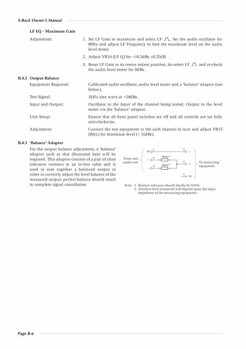
B.4.3 ‘Balance’ Adaptor
For the output balance adjustment, a ‘balance’adaptor such as that illustrated here will berequired. This adaptor consists of a pair of closetolerance resistors in an in-line cable and isused to sum together a balanced output inorder to correctly adjust the level balance of themeasured output; perfect balance should resultin complete signal cancellation.
5K01**
5K01**
2
3
1
2
3
1
0V
+
–
0V
+
–
To measuring equipment
From unit under test
1
2 1
Resistor tolerance should ideally be 0.01%Absolute level measured will depend upon the inputimpedence of the measuring equipment.
1.2.
Note
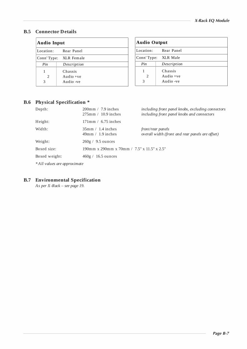
B.5 Connector Details
B.6 Physical Specification *Depth: 200mm / 7.9 inches including front panel knobs, excluding connectors
275mm / 10.9 inches including front panel knobs and connectors
Height: 171mm / 6.75 inches
Width: 35mm / 1.4 inches front/rear panels49mm / 1.9 inches overall width (front and rear panels are offset)
Weight: 260g / 9.5 ounces
Boxed size: 190mm x 290mm x 70mm / 7.5" x 11.5" x 2.5"
Boxed weight: 460g / 16.5 ounces
* All values are approximate
B.7 Environmental SpecificationAs per X-Rack – see page 19.
Audio Output
Location: Rear Panel
Conn' Type: XLR Male
Pin Description
1 Chassis2 Audio +ve
3 Audio -ve
Audio Input
Location: Rear Panel
Conn' Type: XLR Female
Pin Description
1 Chassis2 Audio +ve
3 Audio -ve
Page B-7
X-Rack EQ Module

Page B-8
X-Rack Owner’s Manual

Page D-1
X-Rack Dynamics Module
D. The Dynamics Module
D.1 ConnectionThe module input and output gains can be set to operate at a nominal level of either+4dBu or –10dBV, using a switch on the connector panel. Select the appropriate levelfor the equipment you are connecting to. If in doubt experiment!
To check the input and output gains, set the compressor Ratio and Threshold controlsfully clockwise and send a signal close to the nominal operating level of your mixer orDAW to the dynamics module. The lower three LEDs of the compression meter shouldlight if the input level matches the selected operating level. Release the switch for+4dBu operation: push it in for –10dBV operation.
D.2 OperationEach dynamics module comprises a compressor/limiter and a gate/expander, bothof which use the same gain element.
The IN button switches the entire section in and out of circuit.
D.2.1 Compressor/Limiter Section
RATIO – When turned to 1:1, the compressor/limiter section is inactive. Turningthe control clockwise increases the compression ratio, giving a true limiter at thefully clockwise position. The compressor normally has an ‘over-easy’ characteristic.Pressing the PK button switches this to peak sensing, and replaces the ‘over-easy’characteristic with a hard knee.
THRESHOLD – Whenever a signal exceeds the level set by this control, thecompressor will start to act at the ratio set by the RATIO control. TheTHRESHOLD and RATIO controls also provide automatic make-up gain, so asyou lower the threshold and introduce more compression, the output level isincreased, maintaining a steady output level regardless of the amount ofcompression.
FST ATK – Normally the attack time is program dependent (3mS – 30mS). Press thisbutton to select a fixed fast attack time (3mS for 20dB gain reduction).
RELEASE – Sets the time constant (speed) with which the compressor returns tonormal gain settings once the signal has passed its maximum.
D.2.2 Gate/Expander Section
This section can act as a ∞:1 Gate or as a 2:1 Expander when the EXP button ispressed.
RANGE – Determines the depth of gating or expansion. When turned fullyanticlockwise (Range = 0), this section is inactive. When turned fully clockwise, agate depth of 40dB can be obtained.
THRESHOLD – Determines the level at which the gate opens or below which gain reduction begins (EXPselected), adjustable from +10dBu to –20dBu. Variable hysteresis is incorporated in the threshold circuitryto prevent spurious triggering of the gate when the signal is close to the threshold level. This means thatthe signal has to decay roughly 2dB below the threshold level before the gate will start to close.
3
2
1SEL
+10 -30
COMPRESSOR
GATE/ EXPANDER
KEY
4 0.1
RELEASE
0.1 4
+10
THRESHOLD
-20
RATIO
1 ∞
RANGE
0 40
PK
FAST ATT
LINK
RELEASE
THRESHOLD
IN
EXP
20
14
10
6
3
HOLD
0 4
FAST ATT
XR618
OUT
IN
+4dBu-10dBV
KEY
1
3
2
Page D-2
X-Rack Owner’s Manual
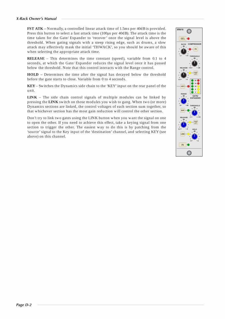
FST ATK – Normally, a controlled linear attack time of 1.5ms per 40dB is provided.Press this button to select a fast attack time (100µs per 40dB). The attack time is thetime taken for the Gate/Expander to ‘recover’ once the signal level is above thethreshold. When gating signals with a steep rising edge, such as drums, a slowattack may effectively mask the initial ‘THWACK’, so you should be aware of thiswhen selecting the appropriate attack time.
RELEASE – This determines the time constant (speed), variable from 0.1 to 4seconds, at which the Gate/Expander reduces the signal level once it has passedbelow the threshold. Note that this control interacts with the Range control.
HOLD – Determines the time after the signal has decayed below the thresholdbefore the gate starts to close. Variable from 0 to 4 seconds.
KEY – Switches the Dynamics side chain to the ‘KEY’ input on the rear panel of theunit.
LINK – The side chain control signals of multiple modules can be linked bypressing the LINK switch on those modules you wish to gang. When two (or more)Dynamics sections are linked, the control voltages of each section sum together, sothat whichever section has the most gain reduction will control the other section.
Don’t try to link two gates using the LINK button when you want the signal on oneto open the other. If you need to achieve this effect, take a keying signal from onesection to trigger the other. The easiest way to do this is by patching from the‘source’ signal to the Key input of the ‘destination’ channel, and selecting KEY (seeabove) on this channel.
SEL
+10 -30
COMPRESSOR
GATE/ EXPANDER
KEY
4 0.1
RELEASE
0.1 4
+10
THRESHOLD
-20
RATIO
1 ∞
RANGE
0 40
PK
FAST ATT
LINK
RELEASE
THRESHOLD
IN
EXP
20
14
10
6
3
HOLD
0 4
FAST ATT
XR618

Page D-3
X-Rack Dynamics Module
D.3 Performance SpecificationThe following pages contain audio performance specification figures for the X-Rack Dynamics Module.No other Solid State Logic products are covered by this document and the performance of other Solid StateLogic products can not be inferred from the data contained herein.
D.3.1 Measurement Conditions
For each set of figures on the following pages, the specific unit and test setup will be stated at thebeginning of that section. Any changes to the specified setup for any particular figure(s) will be detailedbeside the figures to which that difference applies.
D.3.2 Measurement References
Unless otherwise specified the references used in this specification are as follows:
• Reference frequency: 1kHz
• Reference level: 0dBu, where 0dBu ≈ 0.775V into any load
• Source impedance of Test Set: 50Ω
• Input impedance of Test Set: 100kΩ
• All unweighted measurements are specified as 22Hz to 22kHz band limited RMS and are expressed inunits of dBu
• All distortion measurements are specified with a 36dB/Octave low pass filter at 80kHz and areexpressed as a percentage
• The onset of clipping (for headroom measurements) should be taken as 1% THD
• Unless otherwise quoted all figures have a tolerance of ±0.5dB or 5%
• All measurements are made with the operating level switch set for +4dBu
D.3.3 Compressor/Limiter
Controls:
Ratio (slope) Variable from 1 to infinity (limit)
Threshold Variable from +10dB to –30dB
Attack Time Normally auto sensing, switchable to 1mS
Release Variable from 0.1 to 4 seconds
The XLogic Channel unit Compressor/Limiter has two modes of signal detection, Peak and RMS. As theirnames suggest these modes of detection either act on peaks of the incoming signals or on their RMS levels.This gives two very different modes of compression and limiting with Peak Mode giving far moredramatic compression characteristics.
D.3.4 Expander/Gate
Controls:
Range Variable from 0 to 40dB
Threshold Variable from –30dB to +10dB
Attack Time Normally auto-sensing, switchable to 150µs
Hold Time Variable from 0 to 4 seconds
Release Time Variable from 0.1 to 4 seconds
The side chain signal can be sourced either from the signal feeding the dynamic or the external Key input.Filters and/or Equaliser can be inserted in the sidechain.
LED meters independently indicate amount of compression and expansion.

Page D-4
X-Rack Owner’s Manual
D.3.5 Measurement Conditions
Signal applied to Input, output measured at Output. All pots anti-clockwise and switches ‘out’ except forDynamics ‘in’.
THD + N (+10dBu applied) < 0.01% at 1kHz
Signal at +20dBu applied to Input, Compressor Threshold set at –20, Compressor Ratio adjusted to give+4dBu at Output. RMS sensing mode selected.
THD + N < 0.3% at 1kHz(Fast Attack Mode) † < 0.05% at 10kHz
THD + N < 0.03% at 1kHz (Slow Attack Mode) < 0.05% at 10kHz
† LF distortion is consistent with attack and release time constants.
Output Headroom > +26dBu at onset of clipping
Frequency Response ±0.2dB from 20Hz to 20kHz–3dB at 130kHz
Noise < –88dBu
D.4 Calibration InformationThe X-Rack Dynamics module is factory calibrated and should only need calibration if a potentiometer orother component has been replaced or if it is suspected that there is a problem with calibration.
In each of the following instructions it is assumed that the lid has been removed and that power has beenapplied. It is also assumed that unless otherwise specified, all switches are released and all front panelpotentiometers are at unity or minimum position as appropriate. The required accuracy for eachadjustment will be specified along with the target value. All level and distortion measurements should bemade with audio-band 20Hz to 20kHz filters unless otherwise specified.
All presets are accessible from the top of the unit.
Note. The unit should be allowed to warm up with power applied for at least 15 minutes prior to any adjustments beingmade.
D.4.1 Dynamics Adjustments
If the dynamics circuitry requires adjustment the following procedure should be followed in the ordershown. All presets are on the 629618 card.
Equipment Required: Calibrated audio oscillator, audio distortion analyser, audio level meter,oscilloscope and a (digital) DC volt meter.
Test Signal: 1kHz sine wave unless specified otherwise, level as specified.
Input and Output: Oscillator to Input A (or B), Output to either the distortion analyser or thelevel meter, as specified below. Use the oscilloscope to monitor themeasured signal.
Unit Setup: Switch the dynamics IN and the EQ and Filter sections OUT, set all of thedynamics controls anti-clockwise and release all switches.
D.4.2 Distortion
Adjustment: 1. Connect the distortion analyser to the Output and set the oscillator levelfor +20dBu.
2. Adjust VR12 for minimum distortion (< 0.02%).
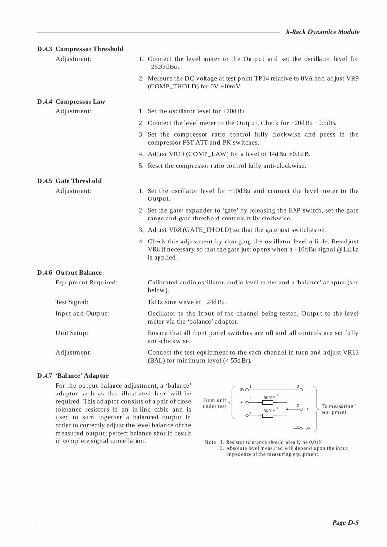
Page D-5
X-Rack Dynamics Module
D.4.3 Compressor Threshold
Adjustment: 1. Connect the level meter to the Output and set the oscillator level for–28.35dBu.
2. Measure the DC voltage at test point TP14 relative to 0VA and adjust VR9(COMP_THOLD) for 0V ±10mV.
D.4.4 Compressor Law
Adjustment: 1. Set the oscillator level for +20dBu.
2. Connect the level meter to the Output. Check for +20dBu ±0.5dB.
3. Set the compressor ratio control fully clockwise and press in thecompressor FST ATT and PK switches.
4. Adjust VR10 (COMP_LAW) for a level of 14dBu ±0.1dB.
5. Reset the compressor ratio control fully anti-clockwise.
D.4.5 Gate Threshold
Adjustment: 1. Set the oscillator level for +10dBu and connect the level meter to theOutput.
2. Set the gate/expander to ‘gate’ by releasing the EXP switch, set the gaterange and gate threshold controls fully clockwise.
3. Adjust VR8 (GATE_THOLD) so that the gate just switches on.
4. Check this adjustment by changing the oscillator level a little. Re-adjustVR8 if necessary so that the gate just opens when a +10dBu signal @ 1kHzis applied.
D.4.6 Output Balance
Equipment Required: Calibrated audio oscillator, audio level meter and a ‘balance’ adaptor (seebelow).
Test Signal: 1kHz sine wave at +24dBu.
Input and Output: Oscillator to the Input of the channel being tested, Output to the levelmeter via the ‘balance’ adaptor.
Unit Setup: Ensure that all front panel switches are off and all controls are set fullyanti-clockwise.
Adjustment: Connect the test equipment to the each channel in turn and adjust VR13(BAL) for minimum level (< 55dBr).
D.4.7 ‘Balance’ Adaptor
For the output balance adjustment, a ‘balance’adaptor such as that illustrated here will berequired. This adaptor consists of a pair of closetolerance resistors in an in-line cable and isused to sum together a balanced output inorder to correctly adjust the level balance of themeasured output; perfect balance should resultin complete signal cancellation.
5K01**
5K01**
2
3
1
2
3
1
0V
+
–
0V
+
–
To measuring equipment
From unit under test
1
2 1
Resistor tolerance should ideally be 0.01%Absolute level measured will depend upon the inputimpedence of the measuring equipment.
1.2.
Note
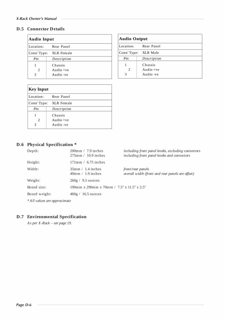
Page D-6
X-Rack Owner’s Manual
D.5 Connector Details
D.6 Physical Specification *Depth: 200mm / 7.9 inches including front panel knobs, excluding connectors
275mm / 10.9 inches including front panel knobs and connectors
Height: 171mm / 6.75 inches
Width: 35mm / 1.4 inches front/rear panels49mm / 1.9 inches overall width (front and rear panels are offset)
Weight: 260g / 9.5 ounces
Boxed size: 190mm x 290mm x 70mm / 7.5" x 11.5" x 2.5"
Boxed weight: 460g / 16.5 ounces
* All values are approximate
D.7 Environmental SpecificationAs per X-Rack – see page 19.
Key Input
Location: Rear Panel
Conn' Type: XLR Female
Pin Description
1 Chassis2 Audio +ve
3 Audio -ve
Audio Output
Location: Rear Panel
Conn' Type: XLR Male
Pin Description
1 Chassis2 Audio +ve
3 Audio -ve
Audio Input
Location: Rear Panel
Conn' Type: XLR Female
Pin Description
1 Chassis2 Audio +ve
3 Audio -ve
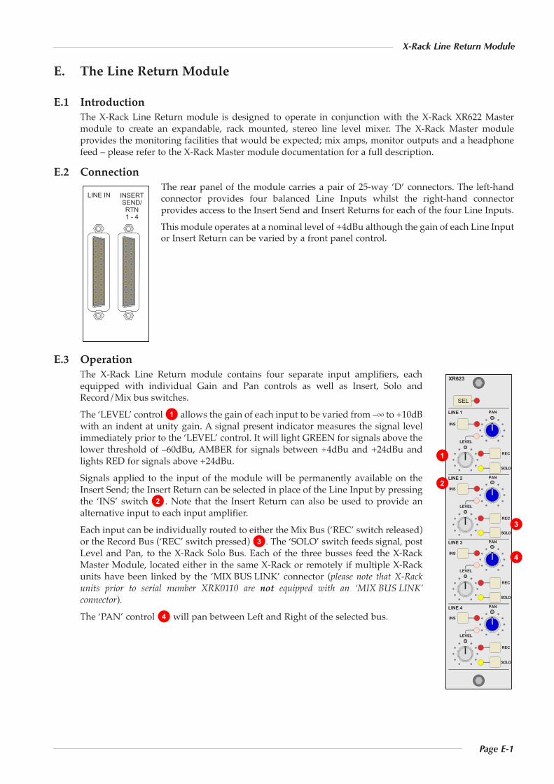
Page E-1
X-Rack Line Return Module
E. The Line Return Module
E.1 IntroductionThe X-Rack Line Return module is designed to operate in conjunction with the X-Rack XR622 Mastermodule to create an expandable, rack mounted, stereo line level mixer. The X-Rack Master moduleprovides the monitoring facilities that would be expected; mix amps, monitor outputs and a headphonefeed – please refer to the X-Rack Master module documentation for a full description.
E.2 ConnectionThe rear panel of the module carries a pair of 25-way ‘D’ connectors. The left-handconnector provides four balanced Line Inputs whilst the right-hand connectorprovides access to the Insert Send and Insert Returns for each of the four Line Inputs.This module operates at a nominal level of +4dBu although the gain of each Line Inputor Insert Return can be varied by a front panel control.
E.3 OperationThe X-Rack Line Return module contains four separate input amplifiers, eachequipped with individual Gain and Pan controls as well as Insert, Solo andRecord/Mix bus switches.The ‘LEVEL’ control allows the gain of each input to be varied from –∞ to +10dBwith an indent at unity gain. A signal present indicator measures the signal levelimmediately prior to the ‘LEVEL’ control. It will light GREEN for signals above thelower threshold of –60dBu, AMBER for signals between +4dBu and +24dBu andlights RED for signals above +24dBu.Signals applied to the input of the module will be permanently available on theInsert Send; the Insert Return can be selected in place of the Line Input by pressingthe ‘INS’ switch . Note that the Insert Return can also be used to provide analternative input to each input amplifier.Each input can be individually routed to either the Mix Bus (‘REC’ switch released)or the Record Bus (‘REC’ switch pressed) . The ‘SOLO’ switch feeds signal, postLevel and Pan, to the X-Rack Solo Bus. Each of the three busses feed the X-RackMaster Module, located either in the same X-Rack or remotely if multiple X-Rackunits have been linked by the ‘MIX BUS LINK’ connector (please note that X-Rackunits prior to serial number XRK0110 are not equipped with an ‘MIX BUS LINK’connector).The ‘PAN’ control will pan between Left and Right of the selected bus.4
3
2
1
SEL
XR623
LEVEL
PAN
INS
REC
SOLO
LINE 1
LEVEL
PAN
INS
REC
SOLO
LINE 2
LEVEL
PAN
INS
REC
SOLO
LINE 3
LEVEL
PAN
INS
REC
SOLO
LINE 4
LINE IN INSERTSEND/RTN1 - 4
1
2
3
4

Page E-2
X-Rack Owner’s Manual
Page E-3
X-Rack Line Return Module
E.4 Performance SpecificationThe following page contains audio performance specification figures for the X-Rack Line Return module.No other Solid State Logic products are covered by this document and the performance of other Solid StateLogic products can not be inferred from the data contained herein.
E.4.1 Measurement ConditionsFor each set of figures on the following pages, the specific unit and test setup will be stated at thebeginning of that section. Any changes to the specified setup for any particular figure(s) will be detailedbeside the figures to which that difference applies.
E.4.2 Measurement ReferencesUnless otherwise specified the references used in this specification are as follows:• Reference frequency: 1kHz• Reference level: 0dBu, where 0dBu ≈ 0.775V into any load• Source impedance of Test Set: 50Ω• Input impedance of Test Set: 100kΩ• All unweighted measurements are specified as 22Hz to 22kHz band limited RMS and are expressed in
units of dBu• All distortion measurements are specified with a 36dB/Octave low pass filter at 80kHz and are
expressed as a percentage• The onset of clipping (for headroom measurements) should be taken as 1% THD• Unless otherwise quoted all figures have a tolerance of ±0.5dB or 5%• All measurements are made with the operating level switch set for +4dBu
E.4.3 Line Input PerformanceSignal applied to Line Input and measured at Mix Bus Insert Send on an X-Rack Master module. InputGain control set to 0dB (indent). Line Input under test routed to Mix Bus, all other Line Inputs routed toRec Bus.
Gain Continuously variable from –∞ to +10dBInput Impedance > 10kΩTHD + Noise < 0.005% from 20Hz to 20kHz(+24dBu applied, 0dB gain)Frequency Response ±0.1dB from 20Hz to 20kHz
–3dB at 150kHzEquivalent Input Noise < –88dBu(Input terminated with 150Ω)
Page E-4
X-Rack Owner’s Manual
E.5 Calibration InformationThe X-Rack Line Return module is factory calibrated and should only need calibration if a potentiometeror other component has been replaced or if it is suspected that there is a problem with calibration.In each of the following instructions it is assumed that an X-Rack Master module is also fitted to theX-Rack and that power has been applied. It is also assumed that unless otherwise specified, all switchesare released and all front panel potentiometers are at unity or minimum position as appropriate. Therequired accuracy for each adjustment will be specified along with the target value. All level anddistortion measurements should be made with audio-band 20Hz to 20kHz filters unless otherwisespecified.These presets are not accessible from the top of the unit, access to the right-hand side of the module willbe required for adjustment.
E.5.1 Line InputEquipment Required: Calibrated audio oscillator and audio level meterTest Signal: 1kHz sinewave @ 0dBuInput and Output: Oscillator to Line Input
Output to the audio level meter from Master module Mix Bus Insert Send(use Left or Right as instructed below)
Unit Setup: 1. Set each Level control to indent (0dB).2. Set each Pan control Left.
E.5.2 Line 1Adjustment: 1. Measure Insert Send Left and adjust VR9 for 0dBu ±0.1dB.
2. Set the Pan control to Centre and adjust VR14 for –4.5dBu ± 0.1dB.3. Measure Insert Send Right and adjust VR13 for –4.5dBu ± 0.1dB.4. Repeat each step until correct.
E.5.3 Line 2Adjustment: 1. Measure Insert Send Left and adjust VR10 for 0dBu ± 0.1dB.
2. Set the Pan control to Centre and adjust VR16 for –4.5dBu ± 0.1dB.3. Measure Insert Send Right and adjust VR15 for –4.5dBu ± 0.1dB.4. Repeat each step until correct.
E.5.4 Line 3Adjustment: 1. Measure Insert Send Left and adjust VR11 for 0dBu ± 0.1dB.
2. Set the Pan control to Centre and adjust VR17 for –4.5dBu ± 0.1dB.3. Measure Insert Send Right and adjust VR18 for –4.5dBu ± 0.1dB.4. Repeat each step until correct.
E.5.5 Line 4Adjustment: 1. Measure Insert Send Left and adjust VR12 for 0dBu ± 0.1dB.
2. Set the Pan control to Centre and adjust VR19 for –4.5dBu ± 0.1dB.3. Measure Insert Send Right and adjust VR20 for –4.5dBu ± 0.1dB.4. Repeat each step until correct.

Page E-5
X-Rack Line Return Module
E.6 Connector Details
Note The Insert Send is a parallel of the Line Input.
Insert Send/ReturnLocation: Rear Panel
Conn’ Type: 25-pin ‘D’ Type FemalePin Description
1 Insert Return 4 (–ve)14 Insert Return 4 (+ve)
2 0V15 Insert Return 3 (–ve)
3 Insert Return 3 (+ve)16 0V
4 Insert Return 2 (–ve)17 Insert Return 2 (+ve)
5 0V18 Insert Return 1 (–ve)
6 Insert Return 1 (+ve)19 0V
7 Insert Send 4 (–ve)20 Insert Send 4 (+ve)
8 0V21 Insert Send 3 (–ve)
9 Insert Send 3 (+ve)22 0V
10 Insert Send 2 (–ve)23 Insert Send 2 (+ve)
11 0V24 Insert Send 1 (–ve)
12 Insert Send 1 (+ve)25 0V
13 n/c
Line InLocation: Rear Panel
Conn’ Type: 25-pin ‘D’ Type FemalePin Description
1 Insert Return 4 (–ve)14 Insert Return 4 (+ve)
2 0V15 Insert Return 3 (–ve)
3 Insert Return 3 (+ve)16 0V
4 Insert Return 2 (–ve)17 Insert Return 2 (+ve)
5 0V18 Insert Return 1 (–ve)
6 Insert Return 1 (+ve)19 0V
7 Line Input 4 (–ve)20 Line Input 4 (+ve)
8 0V21 Line Input 3 (–ve)
9 Line Input 3 (+ve)22 0V
10 Line Input 2 (–ve)23 Line Input 2 (+ve)
11 0V24 Line Input 1 (–ve)
12 Line Input 1 (+ve)25 0V
13 n/c
Page E-6
X-Rack Owner’s Manual
E.7 Physical Specification *Depth: 200mm / 7.9 inches including front panel knobs, excluding connectors
275mm / 10.9 inches including front panel knobs and connectors
Height: 171mm / 6.75 inchesWidth: 35mm / 1.4 inches front/rear panels
49mm / 1.9 inches overall width (front and rear panels are offset)
Weight: 260g / 9.5 ouncesBoxed size: 190mm x 290mm x 70mm / 7.5" x 11.5" x 2.5"Boxed weight: 460g / 16.5 ounces* All values are approximate
E.8 Environmental SpecificationAs per X-Rack – see page 19.
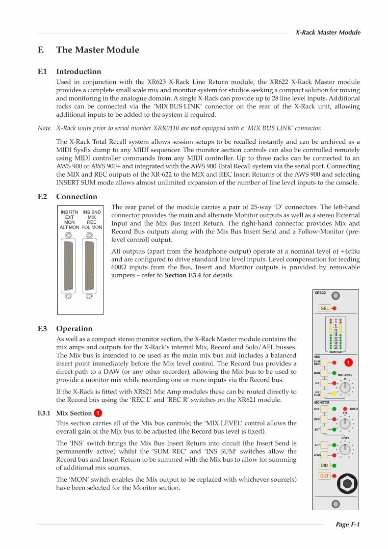
Page F-1
X-Rack Master Module
F. The Master Module
F.1 IntroductionUsed in conjunction with the XR623 X-Rack Line Return module, the XR622 X-Rack Master moduleprovides a complete small scale mix and monitor system for studios seeking a compact solution for mixingand monitoring in the analogue domain. A single X-Rack can provide up to 28 line level inputs. Additionalracks can be connected via the ‘MIX BUS LINK’ connector on the rear of the X-Rack unit, allowingadditional inputs to be added to the system if required.
Note. X-Rack units prior to serial number XRK0110 are not equipped with a ‘MIX BUS LINK’ connector.
The X-Rack Total Recall system allows session setups to be recalled instantly and can be archived as aMIDI SysEx dump to any MIDI sequencer. The monitor section controls can also be controlled remotelyusing MIDI controller commands from any MIDI controller. Up to three racks can be connected to anAWS 900 or AWS 900+ and integrated with the AWS 900 Total Recall system via the serial port. Connectingthe MIX and REC outputs of the XR-622 to the MIX and REC Insert Returns of the AWS 900 and selectingINSERT SUM mode allows almost unlimited expansion of the number of line level inputs to the console.
F.2 ConnectionThe rear panel of the module carries a pair of 25-way ‘D’ connectors. The left-handconnector provides the main and alternate Monitor outputs as well as a stereo ExternalInput and the Mix Bus Insert Return. The right-hand connector provides Mix andRecord Bus outputs along with the Mix Bus Insert Send and a Follow-Monitor (pre-level control) output.All outputs (apart from the headphone output) operate at a nominal level of +4dBuand are configured to drive standard line level inputs. Level compensation for feeding600Ω inputs from the Bus, Insert and Monitor outputs is provided by removablejumpers – refer to Section F.3.4 for details.
F.3 OperationAs well as a compact stereo monitor section, the X-Rack Master module contains themix amps and outputs for the X-Rack’s internal Mix, Record and Solo/AFL busses.The Mix bus is intended to be used as the main mix bus and includes a balancedinsert point immediately before the Mix level control. The Record bus provides adirect path to a DAW (or any other recorder), allowing the Mix bus to be used toprovide a monitor mix while recording one or more inputs via the Record bus.If the X-Rack is fitted with XR621 Mic Amp modules these can be routed directly tothe Record bus using the ‘REC L’ and ‘REC R’ switches on the XR621 module.
F.3.1 Mix SectionThis section carries all of the Mix bus controls; the ‘MIX LEVEL’ control allows theoverall gain of the Mix bus to be adjusted (the Record bus level is fixed).The ‘INS’ switch brings the Mix Bus Insert Return into circuit (the Insert Send ispermanently active) whilst the ‘SUM REC’ and ‘INS SUM’ switches allow theRecord bus and Insert Return to be summed with the Mix bus to allow for summingof additional mix sources.The ‘MON’ switch enables the Mix output to be replaced with whichever source(s)have been selected for the Monitor section.
1
SEL
XR622
MIX LEVEL
AFL
LEVEL
MIX
REC
MONITOR
SUM
MON
SUM
INS
INS
REC
MIX
EXT
ALT
MONO
SOLO
DIM
CUT
MONITOR
0369
1215182430364248
INS RTNEXTMON
ALT MON
INS SNDMIXREC
FOL MON
1
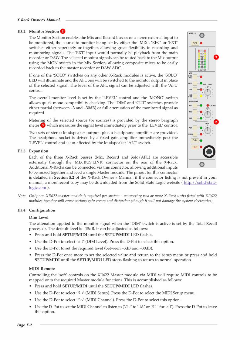
Page F-2
X-Rack Owner’s Manual
F.3.2 Monitor SectionThe Monitor Section enables the Mix and Record busses or a stereo external input tobe monitored, the source to monitor being set by either the ‘MIX’, ‘REC’ or ‘EXT’switches either seperately or together, allowing great flexibility in recording andmontitoring signals. The ‘EXT’ input would normally be playback from the mainrecorder or DAW. The selected monitor signals can be routed back to the Mix outputusing the MON switch in the Mix Section, allowing composite mixes to be easilyrecorded back to the master recorder or DAW ADC.If one of the ‘SOLO’ switches on any other X-Rack modules is active, the ‘SOLO’LED will illuminate and the AFL bus will be switched to the monitor output in placeof the selected signal. The level of the AFL signal can be adjusted with the ‘AFL’control.The overall monitor level is set by the ‘LEVEL’ control and the ‘MONO’ switchallows quick mono compatibility checking. The ‘DIM’ and ‘CUT’ switches provideeither partial (between –3 and –30dB) or full attenuation of the monitored signal asrequired.Metering of the selected source (or sources) is provided by the stereo bargraphmeter which measures the signal level immediately prior to the ‘LEVEL’ control.Two sets of stereo loudspeaker outputs plus a headphone amplifier are provided.The headphone socket is driven by a fixed gain amplifier immediately post the‘LEVEL’ control and is un-affected by the loudspeaker ‘ALT’ switch.
F.3.3 ExpansionEach of the three X-Rack busses (Mix, Record and Solo/AFL) are accessibleexternally through the ‘MIX BUS LINK’ connector on the rear of the X-Rack.Additional X-Racks can be connected via this connector, allowing additional inputsto be mixed together and feed a single Master module. The pinout for this connectoris detailed in Section 5.2 of the X-Rack Owner’s Manual; if the connector listing is not present in yourmanual, a more recent copy may be downloaded from the Solid State Logic website ( http://solid-state-logic.com ).
Note. Only one XR622 master module is required per system – connecting two or more X-Rack units fitted with XR622modules together will cause serious gain errors and distortion (though it will not damage the system electronics).
F.3.4 ConfigurationDim LevelThe attenation applied to the monitor signal when the ‘DIM’ switch is active is set by the Total Recallprocessor. The default level is –15dB, it can be adjusted as follows:• Press and hold SETUP/MIDI until the SETUP/MIDI LED flashes.• Use the D-Pot to select ‘d1’ (DIM Level). Press the D-Pot to select this option.• Use the D-Pot to set the required level (between –3dB and –30dB).• Press the D-Pot once more to set the selected value and return to the setup menu or press and hold
SETUP/MIDI until the SETUP/MIDI LED stops flashing to return to normal operation.
MIDI RemoteControlling the ‘soft’ controls on the XR622 Master module via MIDI will require MIDI controls to bemapped onto the required Master module functions. This is accomplished as follows:• Press and hold SETUP/MIDI until the SETUP/MIDI LED flashes.• Use the D-Pot to select ‘m1’ (MIDI Setup). Press the D-Pot to select the MIDI Setup menu.• Use the D-Pot to select ‘ck’ (MIDI Channel). Press the D-Pot to select this option.• Use the D-Pot to set the MIDI Channel to listen to (‘01’ to ‘16’ or ‘al’ for ‘all’). Press the D-Pot to leave
this option.
3
2
SEL
XR622
MIX LEVEL
AFL
LEVEL
MIX
REC
MONITOR
SUM
MON
SUM
INS
INS
REC
MIX
EXT
ALT
MONO
SOLO
DIM
CUT
MONITOR
0369
1215182430364248
2
3
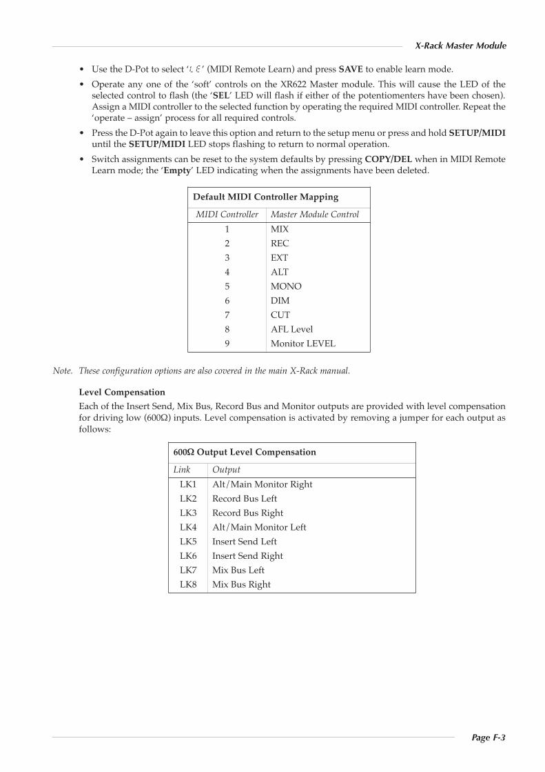
Page F-3
X-Rack Master Module
• Use the D-Pot to select ‘le’ (MIDI Remote Learn) and press SAVE to enable learn mode.• Operate any one of the ‘soft’ controls on the XR622 Master module. This will cause the LED of the
selected control to flash (the ‘SEL’ LED will flash if either of the potentiomenters have been chosen).Assign a MIDI controller to the selected function by operating the required MIDI controller. Repeat the‘operate – assign’ process for all required controls.
• Press the D-Pot again to leave this option and return to the setup menu or press and hold SETUP/MIDIuntil the SETUP/MIDI LED stops flashing to return to normal operation.
• Switch assignments can be reset to the system defaults by pressing COPY/DEL when in MIDI RemoteLearn mode; the ‘Empty’ LED indicating when the assignments have been deleted.
Note. These configuration options are also covered in the main X-Rack manual.
Level CompensationEach of the Insert Send, Mix Bus, Record Bus and Monitor outputs are provided with level compensationfor driving low (600Ω) inputs. Level compensation is activated by removing a jumper for each output asfollows:
Default MIDI Controller Mapping
MIDI Controller Master Module Control1 MIX2 REC3 EXT4 ALT5 MONO6 DIM7 CUT8 AFL Level9 Monitor LEVEL
600Ω Output Level Compensation
Link OutputLK1 Alt/Main Monitor RightLK2 Record Bus LeftLK3 Record Bus RightLK4 Alt/Main Monitor LeftLK5 Insert Send LeftLK6 Insert Send RightLK7 Mix Bus LeftLK8 Mix Bus Right
Page F-4
X-Rack Owner’s Manual
F.4 Performance SpecificationThe following page contains audio performance specification figures for the X-Rack Master module. Noother Solid State Logic products are covered by this document and the performance of other Solid StateLogic products can not be inferred from the data contained herein.
F.4.1 Measurement ConditionsFor each set of figures on the following pages, the specific unit and test setup will be stated at thebeginning of that section. Any changes to the specified setup for any particular figure(s) will be detailedbeside the figures to which that difference applies.
F.4.2 Measurement ReferencesUnless otherwise specified the references used in this specification are as follows:• Reference frequency: 1kHz• Reference level: 0dBu, where 0dBu ≈ 0.775V into any load• Source impedance of Test Set: 50Ω• Input impedance of Test Set: 100kΩ• All unweighted measurements are specified as 22Hz to 22kHz band limited RMS and are expressed in
units of dBu• All distortion measurements are specified with a 36dB/Octave low pass filter at 80kHz and are
expressed as a percentage• The onset of clipping (for headroom measurements) should be taken as 1% THD• Unless otherwise quoted all figures have a tolerance of ±0.5dB or 5%• All measurements are made with the operating level switch set for +4dBu
F.4.3 Mix Bus PerformanceSignal applied to one channel of an X-Rack Line Input module and routed to Mix Bus. Signal measuredon Mix Output. All other inputs un-routed from the bus under test. Mix Bus Gain control set to 0dB.
Gain Continuously variable from –∞ to 0dBTHD + Noise < 0.005% from 20Hz to 10kHz,(+24dBu applied, 0dB gain) < 0.008% at 20kHzFrequency Response ±0.1dB from 20Hz to 20kHz
–3dB at 150kHzEquivalent Input Noise < –88dBu(Input terminated with 150Ω)
F.4.4 Record Bus PerformanceSignal applied to one channel of an X-Rack Line Input module and routed to Record Bus. Signal measuredon Record Output. All other inputs un-routed from the bus under test.
THD + Noise < 0.005% from 20Hz to 20kHz(+24dBu applied, 0dB gain)Frequency Response ±0.1dB from 20Hz to 20kHz
–3dB at 150kHzEquivalent Input Noise < –88dBu(Input terminated with 150Ω)
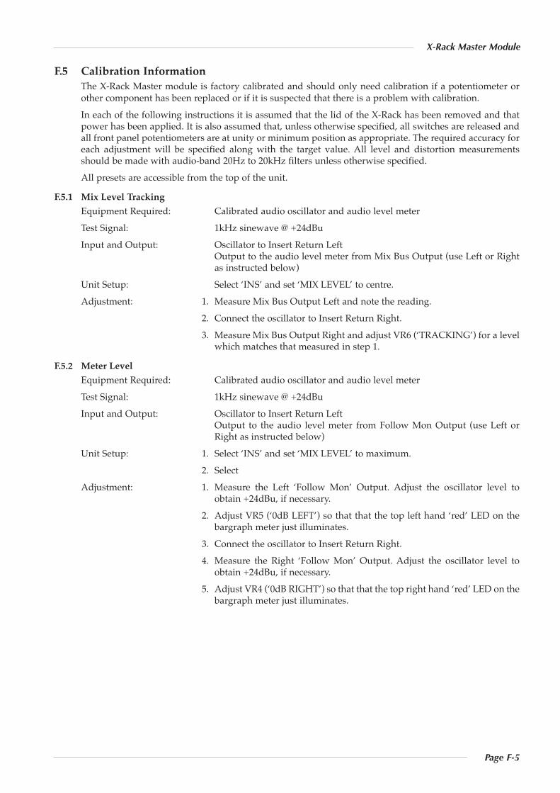
Page F-5
X-Rack Master Module
F.5 Calibration InformationThe X-Rack Master module is factory calibrated and should only need calibration if a potentiometer orother component has been replaced or if it is suspected that there is a problem with calibration.In each of the following instructions it is assumed that the lid of the X-Rack has been removed and thatpower has been applied. It is also assumed that, unless otherwise specified, all switches are released andall front panel potentiometers are at unity or minimum position as appropriate. The required accuracy foreach adjustment will be specified along with the target value. All level and distortion measurementsshould be made with audio-band 20Hz to 20kHz filters unless otherwise specified.All presets are accessible from the top of the unit.
F.5.1 Mix Level TrackingEquipment Required: Calibrated audio oscillator and audio level meterTest Signal: 1kHz sinewave @ +24dBuInput and Output: Oscillator to Insert Return Left
Output to the audio level meter from Mix Bus Output (use Left or Rightas instructed below)
Unit Setup: Select ‘INS’ and set ‘MIX LEVEL’ to centre.Adjustment: 1. Measure Mix Bus Output Left and note the reading.
2. Connect the oscillator to Insert Return Right.3. Measure Mix Bus Output Right and adjust VR6 (‘TRACKING’) for a level
which matches that measured in step 1.
F.5.2 Meter LevelEquipment Required: Calibrated audio oscillator and audio level meterTest Signal: 1kHz sinewave @ +24dBuInput and Output: Oscillator to Insert Return Left
Output to the audio level meter from Follow Mon Output (use Left orRight as instructed below)
Unit Setup: 1. Select ‘INS’ and set ‘MIX LEVEL’ to maximum.2. Select
Adjustment: 1. Measure the Left ‘Follow Mon’ Output. Adjust the oscillator level toobtain +24dBu, if necessary.
2. Adjust VR5 (‘0dB LEFT’) so that that the top left hand ‘red’ LED on thebargraph meter just illuminates.
3. Connect the oscillator to Insert Return Right.4. Measure the Right ‘Follow Mon’ Output. Adjust the oscillator level to
obtain +24dBu, if necessary.5. Adjust VR4 (‘0dB RIGHT’) so that that the top right hand ‘red’ LED on the
bargraph meter just illuminates.

Page F-6
X-Rack Owner’s Manual
F.6 Connector Details
HeadphonesLocation: Front Panel
Conn’ Type: Stereo 1/4" Jack SocketPin DescriptionTip Left
RingSleeve 0V
PL2Location: Internal
Conn’ Type: 16-pin IDC PlugPin Description
n/a For Future Expansion
Ins Rtn, Ext, Mon, Alt MonLocation: Rear Panel
Conn’ Type: 25-pin ‘D’ Type FemalePin Description
1 Alt Monitor Out Right (+ve)14 Alt Monitor Out Right (–ve)
2 0V15 Alt Monitor Out Left (+ve)
3 Alt Monitor Out Left (–ve)16 0V
4 Main Monitor Out Right (+ve)17 Main Monitor Out Right (–ve)
5 0V18 Main Monitor Out Left (+ve)
6 Main Monitor Out Left (–ve)19 0V
7 External Input Right (+ve)20 External Input Right (–ve)
8 0V21 External Input Left (+ve)
9 External Input Left (–ve)22 0V
10 Mix Insert Return Right (+ve)23 Mix Insert Return Right (–ve)
11 0V24 Mix Insert Return Left (+ve)
12 Mix Insert Return Left (–ve)25 0V
13 n/c
Ins Snd, Mix, Rec, Fol MonLocation: Rear Panel
Conn’ Type: 25-pin ‘D’ Type FemalePin Description
1 Follow Monitor Right (+ve)14 Follow Monitor Right (–ve)
2 0V15 Follow Monitor Left (+ve)
3 Follow Monitor Left (–ve)16 0V
4 Record Output Right (+ve)17 Record Output Right (–ve)
5 0V18 Record Output Left (+ve)
6 Record Output Left (–ve)19 0V
7 Mix Output Right (+ve)20 Mix Output Right (–ve)
8 0V21 Mix Output Left (+ve)
9 Mix Output Left (–ve)22 0V
10 Mix Insert Send Right (+ve)23 Mix Insert Send Right (–ve)
11 0V24 Mix Insert Send Left (+ve)
12 Mix Insert Send Left (–ve)25 0V
13 n/c
Page F-7
X-Rack Master Module
F.7 Physical Specification *Depth: 200mm / 7.9 inches including front panel knobs, excluding connectors
275mm / 10.9 inches including front panel knobs and connectors
Height: 171mm / 6.75 inchesWidth: 35mm / 1.4 inches front/rear panels
49mm / 1.9 inches overall width (front and rear panels are offset)
Weight: 260g / 9.5 ouncesBoxed size: 190mm x 290mm x 70mm / 7.5" x 11.5" x 2.5"Boxed weight: 460g / 16.5 ounces* All values are approximate
F.8 Environmental SpecificationAs per X-Rack – see page 19.

Page F-8
X-Rack Owner’s Manual