Embed Size (px)
Citation preview

X-3Terrain King
15 ' Flex Wing3 Gearbox Model
© 2003 Alamo Group Inc.
COMPLETE PARTSLISTING
ALAMO INDUSTRIAL1502 E. WalnutSeguin, Texas 78155830-372-3551
2003 Edition
Archive ManualPart No. 02980264
ARCHIVE BOOKApr. 1975 (S/N X-3-33388)
toApr. 1978 (S/N X-3-36782)

Alamo Industrial (Terrain King)15 foot Flex Wing Mowers
Model - 3 Gearbox 15 ft. / Flex Wing Mowers
Production Date Serial NumberStart.........to....End Start s/n...............to.... End s/n
530............ May 1968........ Nov. 1973* TK530-07195............... TK530-21446*
CP180....... Dec. 1973........ Mar. 1976* CP180-31188............... CP180-34724*
X-3............ Apr. 1975......... Apr. 1978* X-3-33388..................... X-3-36782*
TK15.......... May 1978......... Sep. 1982* TK15-36783.................. TK15-39979*
TK15HD... Oct. 1982......... May 1987* TK15HD-39980............ TK15HD-46051*
A315...... Mar. 1990........ Sep. 1990* A315-01001............. A315-10080*
* End of Production for this Model
Model - 4 Gearbox 15 ft. Flex Wing Mowers
Production Date Serial NumberStart.........to....End Start s/n...............to... End s/n
TK15-IV.... Mar. 1985........ May. 1987* TK15-IV-42840............. TK15-IV-46051*
AG15-IV.... Jun. 1987........ Mar. 2002* AG15-IV-01001............. AG15-IV-04643*
A415...... Jun. 1990........ Dec. 2002* A415-01001............. A415-14000*
ST15........ Jan 2002........ Current ST15-C31500564205.. ST15-Current
* End of Production for this Model
Archive Manual Part Numbers
TK530........................ 02980262 TK15-IV....................... 00761652
CP180........................ 02980263 AG15-IV...................... 00761652
X-3.............................. 02980264 A315........................... 02980317
TK15.......................... 02980265 A415........................... 02980316
TK 15HD.....................02980265 ST15........................... 02980337
Index - 3X-3 (Archive Book) 08/03
© 2002 Alamo Group Inc.
ITEM PAGE NO.
AXLE ARMCenter Axle Single Wheel
X-3-33388 (Apr. 1975) to X-3-36782 (Apr. 1978)......................... 32Center Axle Dual Wheel
X-3-33388 (Apr. 1975) to X-3-36782 (Apr. 1978)........................... 32Wing Axle Single Wheel Only
X-3-33388 (Apr. 1975) to X-3-36782 (Apr. 1978)........................... 33
BLADE CARRIERS & BLADESCenter Section
X-3-33388 (Apr. 1975) to X-3-36782 (Apr. 1978)........................... 30Wing Section
X-3-33388 (Apr. 1975) to X-3-36782 (Apr. 1978)........................... 31
CHAIN GUARDSX-3-33388 (Apr. 1975) to to X-3-36782 (Apr. 1978)...........................46 thru 50
COUNTER WEIGHT (10 foot Model)TK10-36783 (May 1978) to X-3-36782 (Apr. 1978)........................ N/A
CONTROL / LEVEL LIFT RODX-3-33388 (Apr. 1975) to X-3-36782 (Apr. 1978).......................... 16, 17
DECK COMPONENT OVERALLX-3-33388 (Apr. 1975) to X-3-36782 (Apr. 1978)........................... 14, 15
DRIVELINEPTOStandard Driveline
X-3-33388 (Apr. 1975) to X-3-36782 (Apr. 1978).......................... 20
JACK SHAFTStandard Driveline
X-3-33388 (Apr. 1975) to X-3-36782 (Apr. 1978).......................... 21
WING, RH & LHStandard Driveline
X-3-33388 (Apr. 1975) to X-3-36782 (Apr. 1978).......................... 22
CLUTCHESStandard Driveline
X-3-33388 (Apr. 1975) to X-3-36782 (Apr. 1978)........................... 22
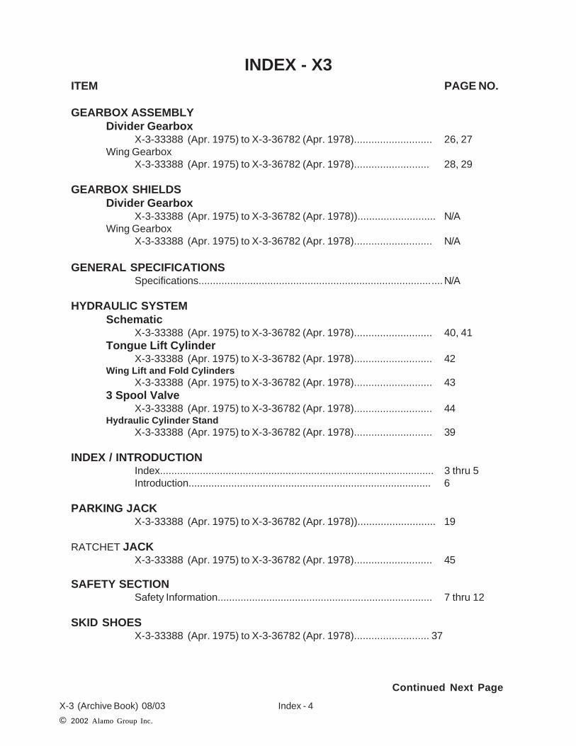
INDEX - X3
Continued Next Page
X-3 (Archive Book) 08/03
© 2002 Alamo Group Inc.
Index - 4
INDEX - X3ITEM PAGE NO.
GEARBOX ASSEMBLYDivider Gearbox
X-3-33388 (Apr. 1975) to X-3-36782 (Apr. 1978)........................... 26, 27Wing Gearbox
X-3-33388 (Apr. 1975) to X-3-36782 (Apr. 1978).......................... 28, 29
GEARBOX SHIELDSDivider Gearbox
X-3-33388 (Apr. 1975) to X-3-36782 (Apr. 1978))........................... N/AWing Gearbox
X-3-33388 (Apr. 1975) to X-3-36782 (Apr. 1978)........................... N/A
GENERAL SPECIFICATIONSSpecifications.....................................................................................N/A
HYDRAULIC SYSTEMSchematic
X-3-33388 (Apr. 1975) to X-3-36782 (Apr. 1978)........................... 40, 41Tongue Lift Cylinder
X-3-33388 (Apr. 1975) to X-3-36782 (Apr. 1978)........................... 42Wing Lift and Fold Cylinders
X-3-33388 (Apr. 1975) to X-3-36782 (Apr. 1978)........................... 433 Spool Valve
X-3-33388 (Apr. 1975) to X-3-36782 (Apr. 1978)........................... 44Hydraulic Cylinder Stand
X-3-33388 (Apr. 1975) to X-3-36782 (Apr. 1978)........................... 39
INDEX / INTRODUCTIONIndex................................................................................................ 3 thru 5Introduction..................................................................................... 6
PARKING JACKX-3-33388 (Apr. 1975) to X-3-36782 (Apr. 1978))........................... 19
RATCHET JACKX-3-33388 (Apr. 1975) to X-3-36782 (Apr. 1978)........................... 45
SAFETY SECTIONSafety Information........................................................................... 7 thru 12
SKID SHOESX-3-33388 (Apr. 1975) to X-3-36782 (Apr. 1978).......................... 37
Continued Next Page

Index - 5X-3 (Archive Book) 08/03
© 2002 Alamo Group Inc.
ITEM PAGE NO.
TONGUE ASSEMBLYX-3-33388 (Apr. 1975) to X-3-36782 (Apr. 1978).......................... 18
TIRE & WHEELAll Models......................................................................................... 34.35
WINCH & STANDWinch Assembly................................................................................ 38Winch Stand...................................................................................... 39
WHEEL HUBX-3-33388 (Apr. 1975) to X-3-36782 (Apr. 1978).......................... 36
INDEX - X3

X-3 (Archive Book) 08/03
© 2002 Alamo Group Inc.
Index - 6
The X3 Archive Book is a complete listing of Parts from the first Unit to the Present. TheProduction Dates, Serial Numbers, Special Notes and Descriptions are furnished to helpfind Replacement Parts. Dimension (if listed) are for Identification of Parts and MAY NOTbe to Manufacturing Specification, Your measurements may vary some from dimensionslisted. Some Parts may be changed and be different than parts listed. Some Modificationmay be required when replacing older parts. Match S/N's listed in this Book with theS/N'slisted at the top of each Parts Page.
Apr. 1975to
Apr. 1978
S/N X-3 -33388to
S/N X-3-36782
FRAMEASSEMBLY
Beginning Production Date
Ending Production Date Componets Listed This Page
PAGE EXAMPLE
For ordering parts the following instructions offered to help eliminate delay
1. The purchase order must include the Name, Address (Ship to Street Address) of thePerson / Organization ordering the parts. Who / How Parts should be Billed. Nameand Phone Number of a Contact Person at your end.
2. The Purchase Order must list clearly the correct Part Number of Part. Quantity of each Part wanted, Complete and correct Description of each Part. All Parts will be shipped as requested depending on availability and/or reasonability of requestcarrier / method.
3. Alamo Industrial reserves the right to substitute parts where applicable and changeprices Without prior notice. Alamo Industrial also reserves the right to Ship Parts themost Reasonable way as determined by Alamo Industrial.
4. Some Parts are unlisted items, which are special production items not normally stocked or built for a limited / special use, These parts may be subject to specialhandling or cannot be priced till ordered. Always Request a quotation for such Partsbefore sending a purchase order.
INTRODUCTION
X3ARCHIVE BOOK
Beginning S/N
Ending S/N

SAFETYSECTION
Safety Section - 7© 2003 Alamo Group Inc.

Safety Section - 8
SAFETY
© 2003 Alamo Group Inc.
Read these assembly instructions through completely and understand thembefore proceeding with the assembly of the equipement.
A safe and careful operator is the best operator. Safety is of primary importance to the manufac-turer and should be to the owner/operator. Most accidents can be avoided by being aware ofyour equipment, your surroundings, and observing certain precautions. The first section of thismanual includes a list of Safety Messages that, if followed, will help protect the operator andbystanders from injury or death. Read and understand these Safety Messages before assem-bling, operating or servicing this Implement. This equipment should only be operated by thosepersons who have read the Manual, who are responsible and trained, and who know how to do
so safely and responsibly.
The Safety Alert Symbol combined with a Signal Word, as seen below, is used throughout thismanual and on decals which are attached to the equipment. The Safety Alert Symbol means:“ATTENTION! BECOME ALERT! YOUR SAFETY IS INVOLVED!” The Symbol and SignalWord are intended to warn the owner/operator of impending hazards and the degree of possibleinjury faced when operating this equipment..
CAUTION! The lowest level of Safety Message; warns of possible injury. Decals located on the Equipment with this Signal Word are Black and Yellow.
WARNING! Serious injury or possible death! Decals are Black and Orange.
DANGER! Imminent death/critical injury. Decals are Red and White. (SG-1)
Practice all usual and customary safe working precautions andabove all---remember safety is up to YOU. Only YOU can preventserious injury or death from unsafe practices.
Safety Section - 9
SAFETY
© 2003Alamo Group Inc.
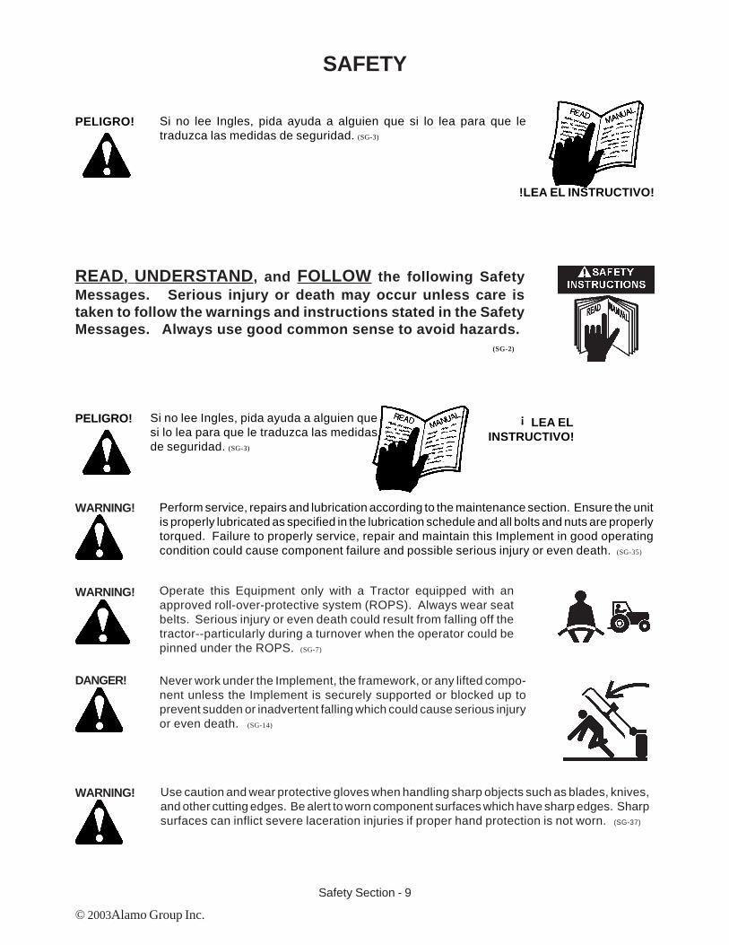
Si no lee Ingles, pida ayuda a alguien que si lo lea para que letraduzca las medidas de seguridad. (SG-3)
PELIGRO!
!LEA EL INSTRUCTIVO!
READ, UNDERSTAND, and FOLLOW the following SafetyMessages. Serious injury or death may occur unless care istaken to follow the warnings and instructions stated in the SafetyMessages. Always use good common sense to avoid hazards.
(SG-2)
!Si no lee Ingles, pida ayuda a alguien quesi lo lea para que le traduzca las medidasde seguridad. (SG-3)
PELIGRO! LEA ELINSTRUCTIVO!
WARNING! Perform service, repairs and lubrication according to the maintenance section. Ensure the unitis properly lubricated as specified in the lubrication schedule and all bolts and nuts are properlytorqued. Failure to properly service, repair and maintain this Implement in good operatingcondition could cause component failure and possible serious injury or even death. (SG-35)
WARNING! Operate this Equipment only with a Tractor equipped with anapproved roll-over-protective system (ROPS). Always wear seatbelts. Serious injury or even death could result from falling off thetractor--particularly during a turnover when the operator could bepinned under the ROPS. (SG-7)
DANGER! Never work under the Implement, the framework, or any lifted compo-nent unless the Implement is securely supported or blocked up toprevent sudden or inadvertent falling which could cause serious injuryor even death. (SG-14)
WARNING! Use caution and wear protective gloves when handling sharp objects such as blades, knives,and other cutting edges. Be alert to worn component surfaces which have sharp edges. Sharpsurfaces can inflict severe laceration injuries if proper hand protection is not worn. (SG-37)
Safety Section - 10
SAFETY
© 2003 Alamo Group Inc.
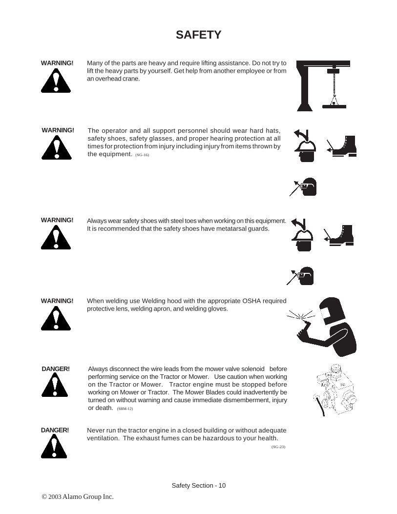
Many of the parts are heavy and require lifting assistance. Do not try tolift the heavy parts by yourself. Get help from another employee or froman overhead crane.
WARNING! The operator and all support personnel should wear hard hats,safety shoes, safety glasses, and proper hearing protection at alltimes for protection from injury including injury from items thrown bythe equipment. (SG-16)
Always wear safety shoes with steel toes when working on this equipment.It is recommended that the safety shoes have metatarsal guards.
When welding use Welding hood with the appropriate OSHA requiredprotective lens, welding apron, and welding gloves.
DANGER! Always disconnect the wire leads from the mower valve solenoid beforeperforming service on the Tractor or Mower. Use caution when workingon the Tractor or Mower. Tractor engine must be stopped beforeworking on Mower or Tractor. The Mower Blades could inadvertently beturned on without warning and cause immediate dismemberment, injuryor death. (SBM-12)
DANGER! Never run the tractor engine in a closed building or without adequateventilation. The exhaust fumes can be hazardous to your health.
(SG-23)
WARNING!
WARNING!
WARNING!

Safety Section - 11
SAFETY
© 2003Alamo Group Inc.
Before starting the mower make sure the area is clear and the floor hasbeen swept. The mower blade can throw objects several hundred feet.Thrown objects could damge property or cause severe bodily injuries evendeath.
WARNING! Make certain that the “Slow Moving Vehicle” (SMV) sign is installed insuch a way as to be clearly visible and legible. When transporting theEquipment use the Tractor flashing warning lights and follow all local trafficregulations. (SG-6)
DANGER! Start tractor only when properly seated in the Tractor seat. Starting atractor in gear can result in injury or death. Read the Tractor operatorsmanual for proper starting instructions. (SG-13)
DANGER! Do not operate this Equipment with hydraulic oil leaking. Oil isexpensive and its presence could present a hazard. Do not check forleaks with your hand! Use a piece of heavy paper or cardboard. High-pressure oil streams from breaks in the line could penetrate the skinand cause tissue damage including gangrene. If oil does penetrate theskin, have the injury treated immediately by a physician knowledge-able and skilled in this procedure. (SG-15)
WARNING! Always read carefully and comply fully with the manufacturers instruc-tions when handling oil, solvents, cleansers, and any other chemicalagent. (SG-22)
DANGER! All Safety Shields, Guards and Safety devices including(but not limited to) - the Deflectors, Chain Guards, SteelGuards, Gearbox Shields, PTO integral shields , andRetractable Door Shields should be used and main-tained in good working condition. All safety devicesshould be inspected carefully at least daily for missingor broken components. Missing, broken, or worn itemsmust be replaced at once to reduce the possibility ofinjury or death from thrown objects, entanglement, orblade contact. (SGM-3)
DANGER!

Safety Section - 12
SAFETY
© 2003 Alamo Group Inc.
DANGER! NEVER use drugs or alcohol immediately before or while operating theTractor and Implement. Drugs and alcohol will affect an operator’salertness and coordination and therefore affect the operator’s ability tooperate the equipment safely. Before operating the Tractor or Imple-ment, an operator on prescription or over-the-counter medication mustconsult a medical professional regarding any side effects of the medi-cation that would hinder their ability to operate the Equipment safely.NEVER knowingly allow anyone to operate this equipment when theiralertness or coordination is impaired. Serious injury or death to theoperator or others could result if the operator is under the influence ofdrugs or alcohol. (SG-27)
DANGER! Operate the Tractor and/or Implement controls only while properly seatedin the Tractor seat with the seat belt securely fastened around you.Inadvertent movement of the Tractor or Implement may cause seriousinjury or death. (SG-29)
WARNING! Engine Exhaust, some of its constituents, and certain vehiclecomponents contain or emit chemicals known to the state ofCalifornia to cause cancer and birth defects or otherreproductive harm. (SG-30)
WARNING! Battery posts, terminals and related accessories contain leadand lead compounds, chemicals known to the state of Califor-nia to cause cancer and birth defects or other reproductiveharm. Wash Hands after handling. (SG-31)
WARNING! Use extreme caution when getting onto the Implement to perform repairs, maintenance andwhen removing accumulated material. Only stand on solid flat surfaces to ensure good footing.Use a ladder or raised stand to access high spots which cannot be reached from gound level.Slipping and falling can cause serious injury or death. (SG-33)
WARNING! Avoid contact with hot surfaces including hydraulic oil tanks, pumps, motors, valves and hoseconnections. Relieve hydraulic pressure before performing maintenance or repairs. Usegloves and eye protection when servicing hot components. Contact with a hot surface or fluidcan cause serious injury from burns or scalding. (SG-34)
WARNING! Avoid contact with hot surfaces of the engine or muffler. Use gloves and eye protection whenservicing hot components. Contact with a hot surface or fluid can cause serious injury fromburns or scalding. (SG-38)

Parts Section 13X-3 (Archive Book) 08/03
© 2003 Alamo Group Inc.
X-3 Archive Book: This is a complete listing of Parts from the first Unit to the Present. TheProduction Dates, Serial Numbers, Special Notes and Descriptions are furnished to help findReplacement Parts. Dimension (if listed) are for Identification of Parts and MAY NOT be toManufacturing Specification, Your measurements may vary some from dimensions listed.Some Parts may be changed and be different than parts listed. Some Modification may berequired when replacing older parts. Match S/N' and Ship Dates if avaialble.
X-3 (Apr. 1975 to Apr. 1978) The X-3 was built from Apr. 1975 (s/n X-3-33388) to Apr. 1978(s/n X-3-36782) then the Model Name was changed to TK15 which used some of the same partsas the X-3 But most parts were different and will not interchange. The X-3-10 was the same asthe X-3 with one Wing removed to make it a 10 foot model.
Gearboxes: The best way to ID the X-3 is by the Wing Gearboxes, They have Ball Bearings.The Blade Bar Splined Hub and the Wing Gearbox Output Shafts are a 1-1/2" Taper w/12 Splines.The Front Cover has 6 Retaining Bolts with 1 Oil Level Plug in front Cover (also look at Wing axleSystem).
Tongue: The Tongue is made with Round Pipe and Tongue clevis Pins to a 360 deg. swivelclevis.
Standard Drivelines: The Standard Drivelines were a 35R Series standard and in a 540 RPMOnly. There is no listing of Optional Drivelines for the X-3. The Wing used a single telescopingShaft and Tube Asy. The Drivelines had an option of Clutches or a Shear Bolt System, 3 requiredper unit. (Shear Bolt Option # 00749595)
Side Skirt X-3 Option: There is no listing of a Side Skirt & Counter Weight asy for the X-3
Chain Guard Option: Some of the Chain Guards are no longer available as assemblies or Parts.The Old Assembly numbers may no longer be valid numbers or may need modifications to installreplacement chain guards.
Hose Quick Disconnect Kit Option: The hose quick disconnect kit was offered as an option,there were 3 each of part # 00275400 per unit on X-3 and 2 each on 10' model.
Dual Wheel Option: The Dual Wheel option was offered for the center section only
Weight: The Shipping Weight of the X-3 is approx 3000 lbs. This will vary with some optionsinstalled or removed.
X-3 Flex Wing RotaryARCHIVE BOOK

Parts Section 14X-3 (Archive Book) 08/03© 2003 Alamo Group Inc.
DECK COMPONENTSX-3
Apr. 1975to
Apr. 1978
X-3-33388to
X-3-36782
Blade Rotation CWRH Wing Section
Blade Rotation CCWLH Wing Section
Blade Rotation CCW Center Section
1
2 3
4
5, 23
6 7
8
9
10
720
11
8
12
13
14, 24
15, 25
16
17
18
19
22
26
26
26
26
16
17
12
13

Parts Section 15X-3 (Archive Book) 08/03
© 2003 Alamo Group Inc.
Item Part No. Qty Description
1. 00750515 1 Tongue Asy2. 00749944 1 Driveline Asy, PTO3. 00750396 1 Jack Shaft Asy4. 00751034 1 Slip Clutch Asy., Center Section
00749595 a/r Shear Bolt Clutch Asy. Center Section5. 00749003 1 Gearbox Asy, Center Section6. ------------- 1 Safety Shield, Center Section7. ------------- 2 Level Rod (See Next Page)8. 00750874 2 Driveline, Wing Section9. 00750524 1 Winch Asy and CylinderStand Asy10. 00750530 1 Axle Arm Asy, LH, Center Section (f/ Single Wheel)11. 00750529 1 Axle Arm Asy, RH, Center Section (f/ Single Wheel)12. 00750522 2 Hinge Pin13. 00023200 4 Retaining Roll Pin14. 00748784 1 Gearbox Asy, RH Wing Section15. 00749008 1 Gearbox Asy, LH Wing Section16. ------------- 1 Safety Shield, Wing Section17. 00758824 2 Slip Clutch Asy., Wing Section
00749595 a/r Shear Bolt Clutch Asy. Center Section18. 00750540 1 Axle Arm, RH Wing Section (Single Wheel)19. 00750541 1 Axle Arm, LH Wing Section (Single Wheel)20. 00749888 1 Parking Jack Asy, (Not Shown)21. 00554600 2 Ratchet Jack, (Not Shown)22. 00750535 1 Skid Shoe LH or RH (Not Shown)23. 00750501 1 Center Blade Bar Asy,Flat Blades (Not Shown)
00750938 1 Center Blade Bar Asy, Updraft Blades (Not Shown)24. 00750506 1 RH Wing Blade Bar Asy, Flat Blades (Not Shown)
00750939 1 RH Wing Blade Bar Asy, Updraft Blades (Not Shown)25. 00750506 1 LH Wing Blade Bar Asy, Flat Blades (Not Shown)
00750937 1 LH Wing Blade Bar Asy, Updraft Blades (Not Shown)26. 00750609 a/r Wheel Hub Asy (4 -Single Wheel / 6 - Dual Wheel)27. 00750583 a/r Chain Guard Kit, Front & Rear Single Curtain (Not Shown)
DECK COMPONENTSX-3
NOTE: Deck Weldments are Listed for Reference Only, SomeMAY NOT be available as a replacement part, ALWAYS
Check Price & Availabilty BEFORE ORDERING Deck Sec-tions as Replacement Parts.
Apr. 1975to
Apr. 1978
X-3-33388to
X-3-36782

Parts Section 16X-3 (Archive Book) 08/03© 2003 Alamo Group Inc.
Item Part No. Qty Description
1. 00008700 a/r Wheel Only, 15" Pneumatic
2. 00019200 a/r Wheel Only, 14" Pneumatic
3. 00025200 a/r Wheel and Sectional Tire Asy, 6 X 9
4. 00750529 1 Axle Arm Asy, Center RH Side
5. 00750530 1 Axle Arm Asy, Center LH Side
6. 00750480 2 Link Pin, 3-11/16" Long
7. 00750473 2 Link Rod
8. 00750395 2 Tongue Cyl. (optional)
9. 00162806 2 Pin
10. 00162802 8 Pin Clip
11. 00750515 1 Tongue Asy.
12. 00162805 2 Tongue Pin
13. 00732800 2 Turnbuckle Asy.
14. 00059500 2 Jam Nut
DECK COMPONENTSX-3
11 10,12
9,10
8
7
14 13
64,5
1,2,3
Apr. 1975to
Apr. 1978
X-3-33388to
X-3-36782
NOTE: There were some of the later X-3 models that were converted to use a later stylelink Rod (item 8), there was drilling and welding required to change this over, once thiswas converted the standard Level Lift Rods listed above would not fit. The modificationKit was # 00751229 (Two Kits required, one each side). The Kits included modificationcomponents (kit # 00751223) as well as Level Rod and Pins. There was an instructionsheet # 007512ID sent with the kit. To kniw if you have this modification installed, look atthe rear axle where lift rod Pin (item 6) connects. There was two spacer bushings thatweld to the inside to make the width 2" wide and the hole (standard is 25/32") willhavebeen drilled out to 1-9/16".

Parts Section 17X-3 (Archive Book) 08/03
© 2003 Alamo Group Inc.
Item Part No. Qty. Description
1. 00732800 1 Turnbuckle Asy.3. 00059500 1 Nut4. 00750473 1 Lift rod Weldment5. 00750480 1 Rear Level Lift Pin6. 00162806 1 Front Level Lift Pin7. 00162802 4 Pin Clip
CONTROL ROD ASYX-3
Note: Qty Shown for 1 Control Rod, 2 Control Rods used on Mower.
13 4 6, 75, 7
NOTE: There were some of the later X-3 models that were converted to use a later stylelink Rod (item 8), there was drilling and welding required to change this over, once thiswas converted the standard Level Lift Rods listed above would not fit. The modificationKit was # 00751229 (Two Kits required, one each side). The Kits included modificationcomponents (kit # 00751223) as well as Level Rod and Pins. There was an instructionsheet # 007512ID sent with the kit. To kniw if you have this modification installed, look atthe rear axle where lift rod Pin (item 6) connects. There was two spacer bushings thatweld to the inside to make the width 2" wide and the hole (standard is 25/32") willhavebeen drilled out to 1-9/16".
Apr. 1975to
Apr. 1978
X-3-33388to
X-3-36782
Parts Section 18X-3 (Archive Book) 08/03
© 2003 Alamo Group Inc.
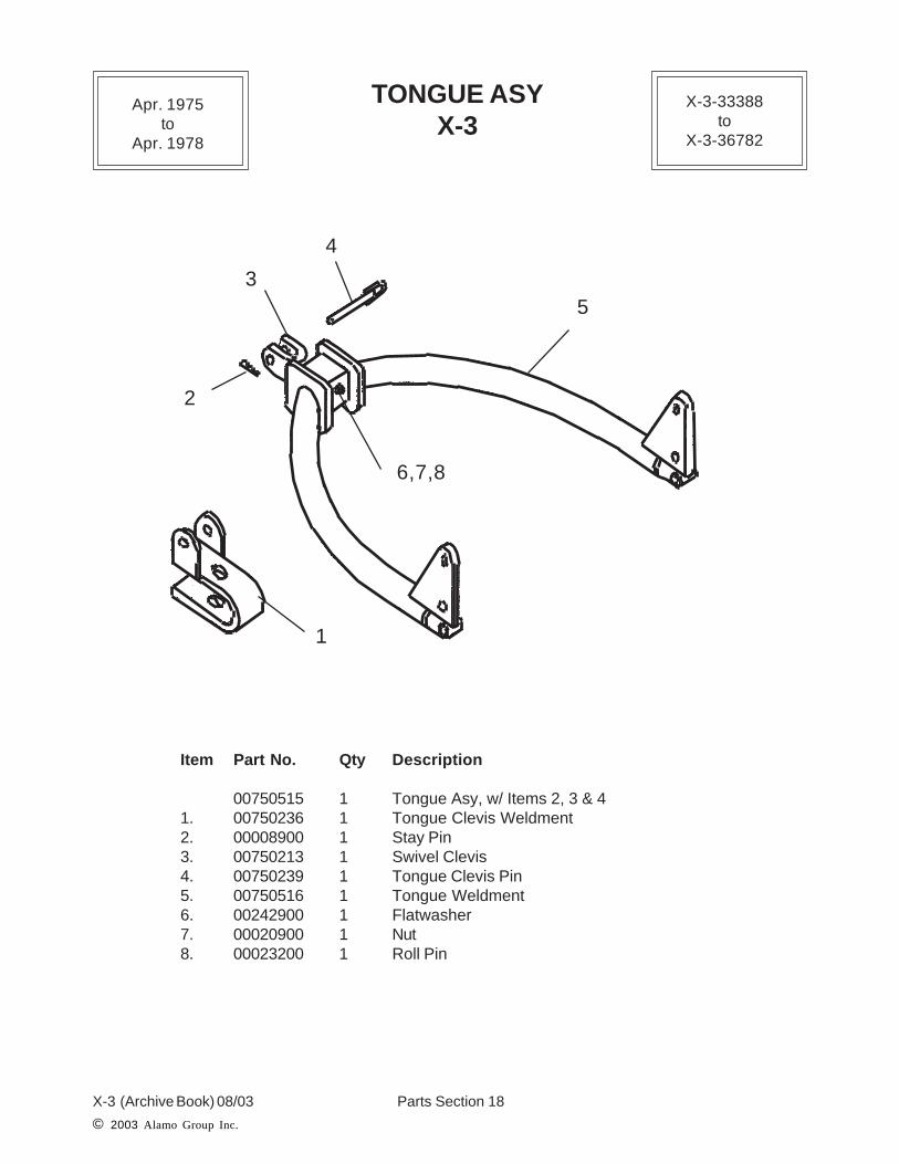
TONGUE ASYX-3
Item Part No. Qty Description
00750515 1 Tongue Asy, w/ Items 2, 3 & 41. 00750236 1 Tongue Clevis Weldment2. 00008900 1 Stay Pin3. 00750213 1 Swivel Clevis4. 00750239 1 Tongue Clevis Pin5. 00750516 1 Tongue Weldment6. 00242900 1 Flatwasher7. 00020900 1 Nut8. 00023200 1 Roll Pin
1
2
3
4
5
6,7,8
Apr. 1975to
Apr. 1978
X-3-33388to
X-3-36782

Parts Section 19X-3 (Archive Book) 08/03
© 2003 Alamo Group Inc.
PARKING JACKX-3
Item Part No. Qty Description
1. 00749888 1 Parking Jak2. 00749892 1 Retaining Pin3. 00000400 1 Cotter Pin
12
3
Apr. 1975to
Apr. 1978
X-3-33388to
X-3-36782

Parts Section 20X-3 (Archive Book) 08/03© 2003 Alamo Group Inc.
PTO DRIVELINEX-3
(Standard)
Item Part No. Qty Description
00749944 1 Driveline Assembly (Items 1 & 2) Both Ends1. 00749966 1 Driveline Tube Half Complete with Shields, (Tractor PTO End)2. 00749965 1 Driveline Shaft Half Complete w/Shields, (Mower Jack Shaft End)3. 00191900 1 Yoke QD, 1-3/8" X 6 Spline (Use # W284A Slide Collar Yoke)4 00749960 1 QD Pin Kit (Replacement Only)5. 00189700 2 Universal Joint (X-Kit)6. 00749417 1 Outer Shield & Bell Assembly
00751168 1 Shield Bearing Repair Kit *7. 00749165 1 Yoke, 1-3/8" X 6 Spline w/ Through Hole (Jack Shaft End)8. 00749416 1 Inner Shield & Bell Assembly
00751168 2 Shield Bearing Repair Kit *9. 00019500 2 Grease Fittings
* Shield Bearing Repair Kit has 1 ea. of # 00749962 Snap Ring, # 00749963 ThrustWasher, # 00749964 Shield Bearing. Will Fit on Inner or Outer Shield.
NOTE: This Driveline has Metal Shields with Square Shaft and Round Tube with a SquareSleeve welded to it. The 35R Driveline was standard on this model.
X-3-33388to
X-3-36782
Apr. 1975to
Apr. 1978
Tractor PTOEnd
Mower JackShaft End
1
2
3, 4
5 6
789
4

Parts Section 21X-3 (Archive Book) 08/03
© 2003 Alamo Group Inc.
JACKSHAFT DRIVELINEX-3
(Standard)
Item Part No. Qty Description
1. 00750396 1 Jack Shaft Asy.2. 00749074 1 Pillow Block Bearing (w/ Grease Fitting
00752176 1 Grease Fitting Only3. 00409200 1 Clutch Yoke w/ Bronze Bushing
00413000 1 Bronze Bushing Only4. 00189700 1 Universal Joint (X-Kit)5. 00002700 2 Flatwasher6. 00019400 2 Locknut7. 00002400 2 Bolt8. 00750949 1 Jack Shaft Shield Asy9. 00310800 2 Snap Ring, f/ Shield
00310700 2 Thrust Washer f/ Shield00183700 2 Nylon Bearing, f/ Shield
10. 00021900 4 Bolt (Not Shown)11. 00011700 4 Lockwasher (Not Shown)12. 00021800 4 Locknut (Not Shown)13. 00749413 1 Bolt (Not Shown)14. 00749017 1 locknut (Not Shown)
Metal Shielded Drivelines with welded tube and 1-3/8" X 6 Spline Stub shaft welded on.
Apr. 1975to
Apr. 1978
X-3-33388to
X-3-36782
92
3
10,11,12
45, 6, 7
8
13,14
1-3/8" X 6 Spline
1

Parts Section 22X-3 (Archive Book) 08/03© 2003 Alamo Group Inc.
WING DRIVELINEX-3
(Standard 35R)
Item Part No. Qty Description
00750874 1 Driveline Assembly (Items 1 & 2) Both Ends, RH or LH Wing1. 00750607 1 Driveline Tube Half Complete with Shields, (Wing Gearbox End)2. 00750606 1 Driveline Shaft Half Complete w/Shields, (Divider Gearbox End)3. 00189700 2 Universal Joint (X-Kit)4. 00409200 1 Yoke, Slip Clutch Flange Yoke w/ Bronze Bushing
271105B 1 Bronze Bushing, (Replacement)5. 00749165 1 Yoke, 1-3/8" X 6 Spline (Divider Gearbox End)6. 00751167 1 Shield Bearing Repair Kit7. 00750877 1 Shield & Bell Asy, Outer8. 00750876 1 Shiled & Bell Asy, Inner9. 00749413 1 Bolt, (Retains Yoke Item 5 to Gearbox)10. 00749017 1 Nut, (Retains Yoke Item 5 to Gearbox)11. 00750925 4 Bolt, (Retains Yoke Item 4 to Clutch)12. 00011700 4 Lockwasher, (Retains Yoke Item 4 to Clutch)13. 00750940 4 Nut, (Retains Yoke Item 4 to Clutch)
NOTE: This Driveline has Metal Shields with Square Shaft and Round Tube with a SquareSleeve welded to it. The 35R Driveline was standard on this model. This Driveline replacesthe old Driveline # 00750397 which did not have Shields on it. If a # 00750397 was orderedthe # 00750874 will be sent. The above parts will fit the old Driveline and the assembly abovewill include shields which the old Driveline did not have.
Apr. 1975to
Apr. 1978
X-3-33388to
X-3-36782
12
3
4
5
6
78
9,10
111213
6

Parts Section 23X-3 (Archive Book) 08/03
© 2003 Alamo Group Inc.
CLUTCH - CENTER & WINGX-3
Item Part No. Qty Description
00751034 a/r Clutch Assembly, Center Gearbox (Items 1 thru 6B)00758824 a/r Clutch Assembly, Wing Gearbox (Items 1 thru 6B)
1. 00748826 1 Drive Plate2. 00748833 2 Friction Disc Facing3. 00748830 1 Adjusting Nut4. 00748829 1 Hub5. 00748831 3 Bellville Spring, Center Section Clutch Only
00748831 2 Bellville Spring, Wing Section Cluch Only6. 00748832 1 Pressure Plate (Front Plate Only)6B. 00748834 1 Back Plate (Back Plate Only)
00751129 1 Drive Plate Asy, Front & Back Plates (6 & 6B)7. 00612703 1 Retaining Ring (Not Shown)8. 00409200 a/r Yoke & Bushing, 35R Driveline
00751243 a/r Yoke & Bushing, 44R Driveline9. 271105B5 1 Bushing Only
To Adjust this Clutch. Tighten Item 3 Adjusting Nut untill all the Slack is removed and all thecomponents are touching as shown above. Make a reference Mark on the Adjusting Nut andcomponents, this will show how many turns you make. Tighten adjusting Nut an additional2-1/8 turns, this is the same for the Center Gearbox clutch and the Wing Clutches.
Apr. 1975to
Apr. 1978
X-3-33388to
X-3-36782
66B
Gearbox InputShaft
12
3
4
58
7
2
9
3 Spring Clutch usedon Center Gearbox &
2 Spring Clutch onWing Driveline. DONOT switch these
from Center to Wing

Parts Section 24X-3 (Archive Book) 08/03© 2003 Alamo Group Inc.
SHEAR BOLT CLUTCHCENTER & WING
X-3
Item Part No. Qty Description
00749595 a/r Shear Bolt Clutch Asy, Center or Wing (items 1 thru 10)1. 00748829 1 Hub2. 00748830 1 Adjusting Nut3. 00748828 1 Bronze Plug4. 00748827 1 Allen Screw5. 00749636 1 Driven Plate & Bushing Weldment6. 00749574 1 Spacer7. 00749573 1 Spacer8. 00748772 2 Top Locking Stop Nut9. 00748758 2 Shear Bolt (Use Grade 2 Only)10. 00749575 1 Drive Plate & Bushing Weldment11. 00612703 1 Retaining Ring (Not Shown)12. 00409200 a/r Yoke & Bushing, 35R Driveline (Not Shown)13. 00413000 1 Bushing Only (Not Shown0
Apr. 1975to
Apr. 1978
X-3-33388to
X-3-36782
1
2
3
4
5
6 7
8
9
10

Parts Section 25X-3 (Archive Book) 08/03
© 2003 Alamo Group Inc.
NOTES

Parts Section 26X-3 (Archive Book) 08/03
© 2003 Alamo Group Inc.
Item Part No. Qty. Description
00749003 -- Gearbox Asy (540RPM) Replaces# 00749867
1 00749477 1 Main Housing2 00749478 1 Cover3 00749479 - Locking Compound4 00749480 1 Cap5 00749481 2 Housing Divider6 00749482 1 Shaft, Blade7 00749483 2 Shaft, Side Output8 00749484 1 Shaft, Input9 00749485 1 Retaining Ring10 00749486 1 Retaining Ring11 00749487 3 Gear, (17 Tooth)12 00749488 1 Bearing Cup13 00749489 1 Seal14 00757533 1 Bearing Cup15 00749491 1 Bearing Cone
Item Part No. Qty. Description
16 00749492 1 Bearing Cup17 00749493 1 Bearing Cone18 00749494 1 Bearing Cone19 00749495 3 Cotter Pin20 00749496 2 Bearing Cup21 00749497 2 Bearing Cone22 00749498 2 Bearing Cup23 00749499 2 Bearing Cone24 00749500 1 Retaining Ring25 00749501 2 Seal26 00749502 1 Plug27 00749503 4 Bolt, Hex Head28 00749504 4 Lockwasher29 00749505 14 Bolt, Hex Head30 00022200 14 Lockwasher31 00749507 1 Plug, Vent
Continued next page
GEARBOX, DIVIDERCENTER SECTION
X-3 (540 RPM)
Apr. 1975to
Apr. 1978
X-3-33388to
X-3-36782
19,36,45
1122,23
520,21
25
7
29,30 29,30
725
20,215
22,23
11
19,36,45
4,39
TopView
1-3/8" X 6Spline
1-3/8" X 6Spline
1-3/8" X 6Spline

Parts Section 27X-3 (Archive Book) 08/03© 2003 Alamo Group Inc.
Torque Item 43 to 100 ft. lbs.
Item Part No. Qty.DescriptionContinued from Previous Page
32 00749508 1 Plug33 00749509 1 Seal34 00749510 1 Bearing Cup35 00749511 1 Bearing Cone36 00749512 3 Nut, Slotted37 00749513 3 Shim, Fiber .005"
00749514 3 Shim, Alum .007"00749515 1 Shim, Alum .020"
38 00749516 1 Shim, Alum .005"00749517 2 Shim, Alum .007"00749518 1 Shim, Alum .020"
39 00749519 2 Shim, .005"00749520 2 Shim, .007"
40 00748539 4 Nut
GEARBOX, DIVIDERCENTER SECTION
X-3 (540 RPM)
Note: Torque Item 40 to100 ft. lbs.
Item Part No. Qty.Description
41 00748538 4 Bolt42 00003901 4 Lockwasher43 00749524 1 Gear, (25 Tooth)44 00749525 1 Gear, (17 Tooth)45 00749526 3 Washer46 00606200 1 Washer47 00606100 1 Nut48 00606000 1 Cotter Pin
Apr. 1975to
Apr. 1978
X-3-33388to
X-3-36782
RightSideView 6
13
34,35
12,15 9
40,41,42
4419,36,45
1026
16,17
4,39
27,28
1
11 24 43 383,29,30
318
3314,15
FrontBack
46, 47, 48
1-3/8" X 6Spline
2" taperedX 15 Spline

Parts Section 28X-3 (Archive Book) 08/03
© 2003 Alamo Group Inc.
GEARBOX ASYWING SECTIONX-3 (540 RPM)
11 13 14, 186 Bolt Input Shaft Bearing Cover
Apr. 1975to
Apr. 1978
X-3-33388to
X-3-36782
1234512345123451234512345
123456123456
1
2
3
4
5
6
7
8
9
10
12
15
16
17
20,21,22
18,19
23
24 25
7
7
26
1-3/8" X 6Spline
1-1/2" Tapered X 12Spline
Parts Section 29X-3 (Archive Book) 08/03© 2003 Alamo Group Inc.
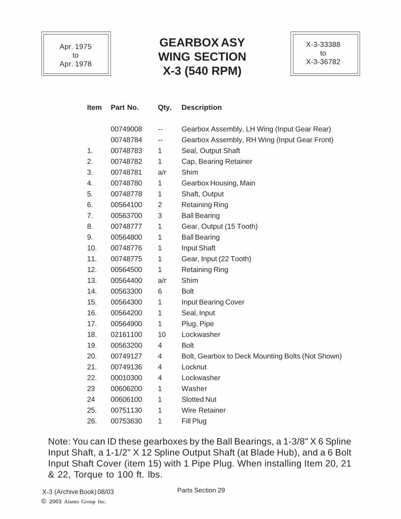
Item Part No. Qty. Description
00749008 -- Gearbox Assembly, LH Wing (Input Gear Rear)
00748784 -- Gearbox Assembly, RH Wing (Input Gear Front)
1. 00748783 1 Seal, Output Shaft
2. 00748782 1 Cap, Bearing Retainer
3. 00748781 a/r Shim
4. 00748780 1 Gearbox Housing, Main
5. 00748778 1 Shaft, Output
6. 00564100 2 Retaining Ring
7. 00563700 3 Ball Bearing
8. 00748777 1 Gear, Output (15 Tooth)
9. 00564800 1 Ball Bearing
10. 00748776 1 Input Shaft
11. 00748775 1 Gear, Input (22 Tooth)
12. 00564500 1 Retaining Ring
13. 00564400 a/r Shim
14. 00563300 6 Bolt
15. 00564300 1 Input Bearing Cover
16. 00564200 1 Seal, Input
17. 00564900 1 Plug, Pipe
18. 02161100 10 Lockwasher
19. 00563200 4 Bolt
20. 00749127 4 Bolt, Gearbox to Deck Mounting Bolts (Not Shown)
21. 00749136 4 Locknut
22. 00010300 4 Lockwasher
23 00606200 1 Washer
24 00606100 1 Slotted Nut
25. 00751130 1 Wire Retainer
26. 00753630 1 Fill Plug
GEARBOX ASYWING SECTIONX-3 (540 RPM)
Note: You can ID these gearboxes by the Ball Bearings, a 1-3/8" X 6 SplineInput Shaft, a 1-1/2" X 12 Spline Output Shaft (at Blade Hub), and a 6 BoltInput Shaft Cover (item 15) with 1 Pipe Plug. When installing Item 20, 21& 22, Torque to 100 ft. lbs.
Apr. 1975to
Apr. 1978
X-3-33388to
X-3-36782

Parts Section 30X-3 (Archive Book) 08/03
© 2003 Alamo Group Inc.
Item Part No. Qty. Description
00750501 a/r Blade Bar Asy w/ Flat Blades, ( Items 1 thru 5 Only)00750938 a/r Blade Bar Asy w/ Updraft Blades (Items 1 thru 5 Only)
1. 00750500 1 Blade Bar Weldment2. 00750788 2-a/r Blade, Updraft (Use # 00752972 Blade Set)
00750121 2-a/r Blade, Flat3. 00735900 2 Blade Bolt (Use # 00752827 Blade Bolt)4. 00748000 2 Lockwasher5. 00747900 2 Nut6. 00606200 1 Washer (Use # 00748547 Washer)7. 00606100 1 Nut, Slotted8. 00606000 1 Cotter Pin (Use # 00751130 Wire)
NOTE: This Blade Bar has a 2" X 15 Spline Tapered Hub where it fits onto Blade Shaftof Gearbox. Center Section Blades are CCW Rotation. Blades are no longer furnished as indi-vidual Blades, use Blade Set # 00752972 (CCW) for Center & LH Wing and # 00752971 (CW)for RH Wing. These are Sets of 2 matched Blades per Part Number. NO Blade Pan Option avail-able
BLADE CARRIERCENTER SECTION
X-3
Apr. 1975to
Apr. 1978
X-3-33388to
X-3-36782
1
22
33
44
5 5
6
7
8
2" X 15 SplineTapered Hub

Parts Section 31X-3 (Archive Book) 08/03
© 2003 Alamo Group Inc.
BLADE CARRIERWING SECTION
X-3
Item Part No. Qty. Description
00750939 a/r Blade Bar Asy w/ Updraft Blades RH Wing, ( Items 1 thru 5 Only)00750937 a/r Blade Bar Asy w/ Updraft Bldaes LH Wing, ( Items 1 thru 5 Only)00750506 a/r Blade Bar Asy w/ Flat Blades RH or LH Wing (items 1 thru 5 Only)
1. 00750505 1 Blade Bar Weldment, RH or LH Wing2. 00750787 2 Blade, Updraft RH Wing (Use # 00752971 Blade Set)
00750788 2 Blade, Updraft LH Wing (Use # 00752972 Blade Set)00750121 4 Blade, Flat LH or RH Wing (Double Edge Blade)
3. 00735900 2 Blade Bolt (Use # 00752827 Blade Bolt)4. 00748000 2 Lockwasher5. 00747900 2 Nut6. 00606200 1 Washer (Use # 00748547 Washer)7. 00606100 1 Nut, Slotted8. 00606000 1 Cotter Pin (Use # 00751130 Wire)
NOTE: This Blade Bar has a 1-1/2" X 12 Spline Tapered Hub where it fits onto Blade Shaftof Gearbox. RH Wing Blades are CW Rotation and LH Wing Blades a CCW Rotation. Bladesare no longer furnished as individual Blades, use Blade Set # 00752972 (CCW) for Center &LH Wing and # 00752971 (CW) for RH Wing. These are Sets of 2 matched Blades per PartNumber.
Apr. 1975to
Apr. 1978
X-3-33388to
X-3-36782
1-1/2" X 12 SplineTapered Hub
1
22
33
44
5 5
6
7
8
Parts Section 32X-3 (Archive Book) 08/03© 2003 Alamo Group Inc.
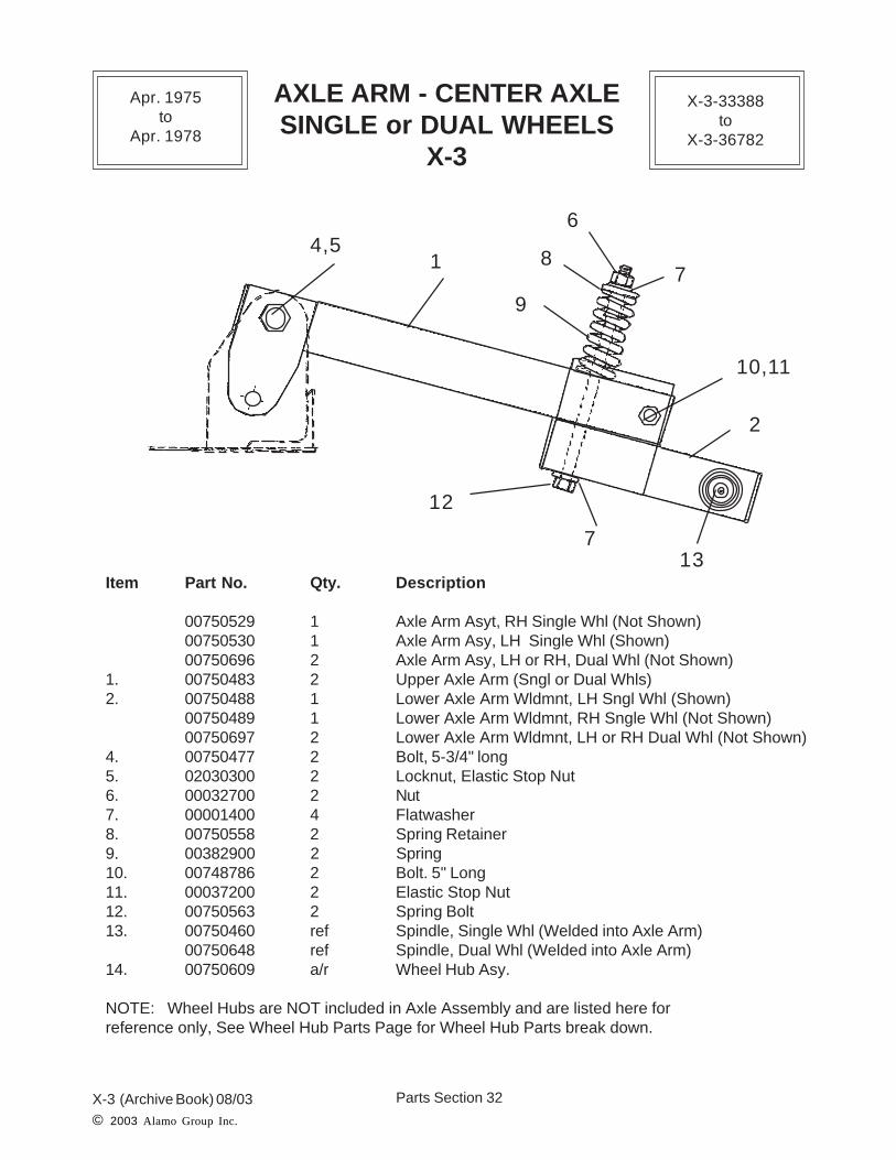
Item Part No. Qty. Description
00750529 1 Axle Arm Asyt, RH Single Whl (Not Shown)00750530 1 Axle Arm Asy, LH Single Whl (Shown)00750696 2 Axle Arm Asy, LH or RH, Dual Whl (Not Shown)
1. 00750483 2 Upper Axle Arm (Sngl or Dual Whls)2. 00750488 1 Lower Axle Arm Wldmnt, LH Sngl Whl (Shown)
00750489 1 Lower Axle Arm Wldmnt, RH Sngle Whl (Not Shown)00750697 2 Lower Axle Arm Wldmnt, LH or RH Dual Whl (Not Shown)
4. 00750477 2 Bolt, 5-3/4" long5. 02030300 2 Locknut, Elastic Stop Nut6. 00032700 2 Nut7. 00001400 4 Flatwasher8. 00750558 2 Spring Retainer9. 00382900 2 Spring10. 00748786 2 Bolt. 5" Long11. 00037200 2 Elastic Stop Nut12. 00750563 2 Spring Bolt13. 00750460 ref Spindle, Single Whl (Welded into Axle Arm)
00750648 ref Spindle, Dual Whl (Welded into Axle Arm)14. 00750609 a/r Wheel Hub Asy.
NOTE: Wheel Hubs are NOT included in Axle Assembly and are listed here forreference only, See Wheel Hub Parts Page for Wheel Hub Parts break down.
AXLE ARM - CENTER AXLESINGLE or DUAL WHEELS
X-3
4,51
12
9
87
6
10,11
2
713
Apr. 1975to
Apr. 1978
X-3-33388to
X-3-36782

Parts Section 33X-3 (Archive Book) 08/03© 2003 Alamo Group Inc.
AXLE ARM - WING AXLEX-3
Item Part No. Qty. Description
00750540 -- Axle Arm Asy, RH (Shown) w/ Items 2,3,4, & 800750541 -- Axle Arm Asy, LH (Not Shown) w/ Items 2,3,4, & 8
1 00750493 1 Axle Arm Weldment, RH (Shown)00750494 1 Axle Arm Weldment, LH (Not Shown)
2 02030300 1 Locknut3. 00750479 1 Bolt4. 00750518 1 Shock Absorber Rod5. 00750558 2 Spring Retainer6 00001400 2 Flatwasher7. 00132002 1 Spring8. 00750481 1 Shock Absorber Pin9. 00695100 4 Jam Nut10. 00750609 a/r Hub Assembly, (Not Shown)11. 00750460 ref Spindle, Single Wheel (Welded into Axle Arm)
NOTE: Wheel Hubs are NOT included in Axle Assembly and are listed here forreference only, See Wheel Hub Parts Page for Wheel Hub Parts break down.
Apr. 1975to
Apr. 1978
X-3-33388to
X-3-36782
1
2, 3
56
4
7 8
9
9 10
Mower Deck

Parts Section 34X-3 (Archive Book) 08/03© 2003 Alamo Group Inc.
WHEEL AND TIRE ASYX-3
(TK15HD-46051 endedproduction on this model)
Apr. 1975to
Apr. 1978
X-3-33388to
X-3-36782
2
3
4, 5
1 wheel only
Install Flat Side of LugNut Against Wheel as
Shown
Laminated Tire orFoam Filled Tire
Wheel BoltsLugnuts
Ribbed Implement Tire
Place Conical Side ofLugnut against Wheel
See Side of Tire forMaximum Pressure
Wheel Bolts
Lugnuts
Maximum InflationPressure 50 PSI Also
See Decal # 00762608
Airplane Tire

Parts Section 35X-3 (Archive Book) 08/03© 2003 Alamo Group Inc.
WHEEL AND TIRE ASYX-3
Item Part No. Description
1 00008700 Wheel, 15 x 5.00 DC (Wheel Only) (Fig. 2)
00019200 Wheel, 14 X 5.00 DC( Wheel Only)
2 00749698 Rib Implement - Tire & Wheel Complete (Fig. 2)
3 00025200 Laminated Puncture-Proof Tire & Wheel
Asy (21" OD) 6.00 x 9 (Fig. 1)
4 00749700 Used Airplane Tire & Wheel 25.5 X 14" (Fig. 2)
00766911 Used Airplane Tire & Wheel Foam Filled
22 X 6.6/6.75 X 10 (use 00766911A in Pairs) (Fig. 1)
00766911A Used Airplane Tire & Wheel Foam Filled (Fig. 1)
24 X 7.7 X 10
5 00764721 Recapped Airplane Tire & Whl 27.75 X 8.75 X 14.5 (Fig. 2)
00750016 Recapped Airplane Tire & Wheel 22 X 5 X 12 Split (Fig. 2)
Wheel (use 00749700 A/R for replacement)
NOTE:It is VERY IMPORTANT on some types of Tires and Wheels how they are mounted, thedirection of travel, the Air Pressure, the way they bolt together, the way the Lug Nuts are
installed and/or other special features that may be special only to that tire and wheel.ALWAYS check for any special instructions for the type Tire and Wheel being used
before ordering or installing any Wheels or Wheel components.
SOME WHEELS LISTED ABOVE WERE NOT USED ON THIS MODEL.Wheeld listed above are the only wheels available at ths time. Be sure to check oldwheels for size. Wheel Bolt pattern is the same only wheel size may be different.
LUGNUT MUST be mounted correctly according to Wheel Design
Lugnut
Conical SideLugbolt
Wheel
Hub
Figure 1
Lugbolt
Wheel
Hub
Figure 2
Lugnut
Conical Side
If Flat Sided Hole If Cone Sided Hole
Apr. 1975to
Apr. 1978
X-3-33388to
X-3-36782

Parts Section 36X-3 (Archive Book) 08/03© 2003 Alamo Group Inc.
WHEEL HUBX-3
Item Part No. Qty. Description00750609 -- Wheel Hub Asy. (w/ Items 1 thru 10)
1. 00750610 1 Wheel Hub w/ Bearing Cups2. 00751137 1 Bearing Cup & Cone Asy (Outer)
00750611 -- Bearing Cone Only (Outer)00750621 -- Bearing Cup Only (Outer)
3. 00751138 1 Bearing Cup & Cone Asy (Inner)00750612 -- Bearing Cone Only (Inner)00750620 -- Bearing Cup Only (Inner)
4. 00750613 5 Stud Bolt5. 00750614 5 Lug Nut6. 00750615 1 Nut7. 00750616 1 Seal8. 00000400 1 Cotter Pin9. 02817200 1 Dust Cap10. 00750618 1 Washer, Keyed11. 00750460 ref Spindle, Single Wheel (Welded into Axle Arm)12. 00750648 ref Spindle, Dual Wheel (Welded into Axle Arm)
NOTE: This Wheel Hub will be replaced by later style Wheel Hub, if ordering # 00750609 or # 00750610 later Style Hub w/ Bearings will be shipped . New Hub will fit the Spindles.
Apr. 1975to
Apr. 1978
X-3-33388to
X-3-36782
1
23
4
5
6
7
8
9
10
11,12
Note: This Hub did not have agrease fitting and had to bedis-asembled every 6 monthsto pack Bearings with grease.Replacement Hub will havegrease fitting in it.

Parts Section 37X-3 (Archive Book) 08/03© 2003 Alamo Group Inc.
Item Part No. Qty. Description
1. 00750535 1 Skid Shoe Kit, RH & LH Wing2. 00019400 4 Locknut (2 ea. Skid Shoe)3. 00749171 4 Bolt (2 ea. Skid Shoe)
SKID SHOEX-3
Apr. 1975to
Apr. 1978
X-3-33388to
X-3-36782
NOTE: When installing Skid Shoe Kit # 00750535 the Side bands on Wings will have to beModified, re-Drilled holes. There is an instruction Sheet ( # 00750992) showing themodification to mount Skid Shoes. The Kit will consist of a LH & RH Skid Shoe andmounting hardware. The Replacement Skid Shoes will be # 00750989 LH Skid Shoe and# 00750993 RH Skid Shoe, Modification will be required to install them.
1
2
3

Parts Section 38X-3 (Archive Book) 08/03
© 2003 Alamo Group Inc.
Item Part No. Qty. Description
00256001 -- Winch Assembly (Use # 00750950)1. 00750936 1 Winch2. 00000801 1 Cable Assembly (includes Items 3, 4 & 5)3. 00000800 1 Cable Only4. 02024600 1 Cable Thimble5. 00001000 1 Cable Clamp
WINCH ASYX-3
12, 34,5
Apr. 1975to
Apr. 1978
X-3-33388to
X-3-36782

Parts Section 39X-3 (Archive Book) 08/03© 2003 Alamo Group Inc.
Item Part No. Qty. Description
1. 00750524 1 Winch & Cylinder Support Stand Weldment2. 00256001 1 Winch Assembly (See Previous Page)3. 00001200 4 Nut4. 00001300 4 Lockwasher5. 00750584 4 Bolt6. 00013901 2 Nut7. 00012101 2 Lockwasher8. 00011400 2 Bolt9. 00750578 1 Retaining Arm, RH or LH10. 00750596 2 Cylinder Vent Plug11. 00008900 2 Stay Pin12. 00750585 2 *Wing Cylinder Lift Kit. (Optional Equipment)
00750398 2 Wing Lift Cylinder Only13. 00059000 2 Bolt14. 00695100 2 Locknut15. 00750311 ref. Bolt16. 00001400 ref. Flatwasher17. 00750549 2 Hose
00025400 2 Adapter18. 00011100 2 Flatwasher
*Note: Wing Cylinder Lift Kits include, Cylinder, Hose, Fitting and mounting Pins / Bolts tomounr Cylinder.
WINCH & CYLINDER STANDX-3
Apr. 1975to
Apr. 1978
X-3-33388to
X-3-36782
9
12
1
3, 4 , 5
2,6,7,8,18
13, 149
12
11
14,15,16
10
17 17

Parts Section 40X-3 (Archive Book) 08/03
© 2003 Alamo Group Inc.
HYDRAULIC SCHEMATICX-3
1
3
13
14
67 9
1
3
13
14
568
10
5
11
1212
123
12121212
121212
12341234
121212
15
16
17
18
17
To Valve End
To Hose End
Note: Valve is shown turnedaround for illustration, Winghoses shown reversed on
valve. Wings connect to twoouter ports and level lift to
center ports.
44
1212
Apr. 1975to
Apr. 1978
X-3-33388to
X-3-36782

Parts Section 41X-3 (Archive Book) 08/03
© 2003 Alamo Group Inc.
Item Part No. Qty. Description
1. 00750398 2 Wing Lift Cyl. Asy. RH or LH
2. 00750584 1 Tongue Cyl Kit, (items 3,4, 5,6,7,8,9)
3. 00750395 2 Tongue Cyl Asy.
4. 00750208 2 Breather Vent Plug
5. 00494800 2 Reducer Bushing
6. 00035400 2 Elbow Adapter, 90 deg.
7. 00750550 1 Hose, 57" Long
8. 00750549 1 Hose, 18" Long
9. 00493900 1 Tee
10. 00750553 1 Nipple, Pipe
11. 00750381 a/r * 3 Spool Valve, Open Center (Optional)
00750382 a/r * 3 Spool Valve, Closed Center (Optional)
12. 00750208 2 Breather Vent Plug
13. 00035400 2 Elbow Adapter, 90 deg.
14. 00749466 2 Hose, 180" Long
15. 00703000 3 Elbow Swivel (Optional QD Coupler)
16. 00702900 3 Nipple, (Optional QD Coupler)
17. 00494800 6 Bushing, (Optional QD Coupler)
18 00275400 3 QD Coupler Asy, Inner & Outer (Optional)
NOTE: Item 10 was not always purchased with unit. Some were supplied by dealers / cus-tomers. Shown and listed as Item 10 only as a reference. The Valve on the unit at the time ofPurchase may have been a Factory Valve and will not be the same as the one listed above.The old Valves used during this period are no longer available as parts. The Valve listedabove will be replaced by a later style Valve assembly. See Valve Parts Page in this section.
HYDRAULIC SCHEMATICX-3
Apr. 1975to
Apr. 1978
X-3-33388to
X-3-36782
Parts Section 42X-3 (Archive Book) 08/03
© 2003 Alamo Group Inc.
TONGUE LIFT CYLINDERX-3
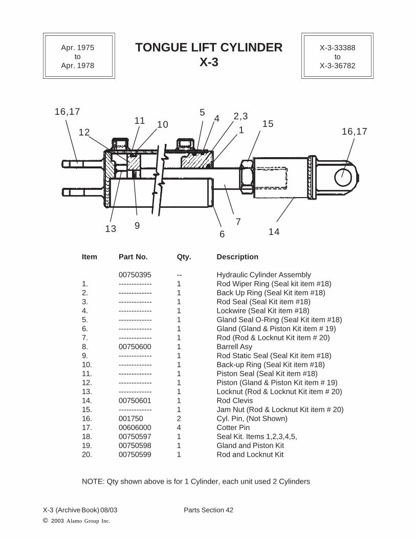
Item Part No. Qty. Description
00750395 -- Hydraulic Cylinder Assembly1. ------------- 1 Rod Wiper Ring (Seal kit item #18)2. ------------- 1 Back Up Ring (Seal Kit item #18)3. ------------- 1 Rod Seal (Seal Kit item #18)4. ------------- 1 Lockwire (Seal Kit item #18)5. ------------- 1 Gland Seal O-Ring (Seal Kit item #18)6. ------------- 1 Gland (Gland & Piston Kit item # 19)7. ------------- 1 Rod (Rod & Locknut Kit item # 20)8. 00750600 1 Barrell Asy9. ------------- 1 Rod Static Seal (Seal Kit item #18)10. ------------- 1 Back-up Ring (Seal Kit item #18)11. ------------- 1 Piston Seal (Seal Kit item #18)12. ------------- 1 Piston (Gland & Piston Kit item # 19)13. ------------- 1 Locknut (Rod & Locknut Kit item # 20)14. 00750601 1 Rod Clevis15. ------------- 1 Jam Nut (Rod & Locknut Kit item # 20)16. 001750 2 Cyl. Pin, (Not Shown)17. 00606000 4 Cotter Pin18. 00750597 1 Seal Kit. Items 1,2,3,4,5,19. 00750598 1 Gland and Piston Kit20. 00750599 1 Rod and Locknut Kit
NOTE: Qty shown above is for 1 Cylinder, each unit used 2 Cylinders
1
2,345
69
101112
13 14
15
7
16,17
16,17
Apr. 1975to
Apr. 1978
X-3-33388to
X-3-36782

Parts Section 43X-3 (Archive Book) 08/03
© 2003 Alamo Group Inc.
WING LIFT CYLINDERX-3
Item Part No. Qty. Description
00750398 -- Hydraulic Cylinder Assembly1. 00750605 1 Barrel Assembly2. ------------- 1 Rod Weldment (See Rod & Locknut Kit item # 16)3. ------------- 1 Locknut (See Rod & Locknut Kit item # 16)4. ------------- 1 Piston (See Gland & Piston Kit item # 15)5. ------------- 1 Gland (See Gland & Piston Kit item # 15)6. ------------- 2 Piston Wiper Ring (See Seal Kit)7. ------------- 1 Piston Seal (See Seal Kit # 14)8. ------------- 1 Piston to Rod Seal (See Seal Kit # 14)9. ------------- 1 Gland Seal, Outer (See Seal Kit # 14)10. ------------- 1 Lockwire (See Seal Kit # 14)11. ------------- 1 Rod to Gland Seal (See Seal Kit # 14)12. ------------- 1 Rod to Gland Seal (See Seal Kit # 14)13. ------------- 1 Rod Wiper Seal (See Seal Kit item # 14)14. 00750602 1 Seal Kit (items 7, 8, 9, 10, 11, 12 & 13)15. 00750603 1 Gland & Piston Kit (items 4 & 5)16. 00750604 1 Rod & Locknut Kit (item 2 & 3)17. 00059000 1 Bolt18. 00695100 2 Nut19. 00750311 1 Bolt20. 00001400 2 Flatwasher
NOTE: Qty shown above is for 1 Cylinder, each unit used 2 Cylinders
Apr. 1975to
Apr. 1978
X-3-33388to
X-3-36782
17,18
18,19,20
13
5
11,1210
9
1 283
6 7
4

Parts Section 44X-3 (Archive Book) 08/03
© 2003 Alamo Group Inc.
THREE SPOOL VALVEX-3
Item Part No. Qty. Description
00750381 a/r Hydraulic Valve Assembly, Open Center00750382 a/r Hydraulic Valve Assembly, Closed Center
1. 00749986 1 Valve Segment Inlet2. 00750000 2 Valve Segment w/ Detent3. 00750364 1 Valve Segment w/o Detent4. 00750002 a/r Valve Segment Outlet, Open Center
00750365 a/r Valve Serment Outlet, Closed Center5. 00750340 3 Adapter, Swivel6. 00750005 20 O-Ring7. 00750006 12 Mylar Washers8. 00749985 2 Attachment Brackets9. 00749999 3 Handle10. 00750377 3 Tie Rod11. 00023500 2 Flatwasher, Used on upper Tie Rod Only12. 00021800 6 Nut
NOTE: The Valves listed above will be replaced as an assembly by a later version Valve and partswill not interchange between the replacement valve and this Valve. Some Parts for the Valveslisted above may no longer be available as parts, Check before ordering.
1
22
3
8
5 55
4
8
7 9
6
101112
Apr. 1975to
Apr. 1978
X-3-33388to
X-3-36782

Parts Section 45X-3 (Archive Book) 08/03© 2003 Alamo Group Inc.
Item Part No. Qty. Description
1. 00554600 1 Ratchet Jack Assembly (Items 1,2 & 3)2. 00748714 2 Pin (Use # 0581000003)3. 00748715 4 Hair Pin clip4. 00748717 2 Rivit, Handle Pins (NLF)
NOTE: The Ratchet Jack was an Optional Order item and was offered in place ofhydraulic cylinders for the Level Lift.
RATCHET JACK ASYX-3
Apr. 1975to
Apr. 1978
X-3-33388to
X-3-36782
1
2
2
3
3
4

Parts Section 46X-3 (Archive Book) 08/03
© 2003 Alamo Group Inc.
CHAIN GUARDSX-3
Item Part No. Part No. Qty. DescriptionSingle DoubleCurtain Curtain
00750583 ------------ a/r Chainguard Kit, Front & Rear, CompleteAssembly (Items 1,2,3,4)
1. 00750592 00750587 1 Front Chain Guard Asy.2. 00750594 00750589 2 Front Wing Chain Guard Asy.3 00750593 00750588 1 Rear Center Chain Guard Asy.4. 00750595 00750590 2 Rear Wing Chain Guard Asy.
1
2 2
34 4
Apr. 1975to
Apr. 1978
X-3-33388to
X-3-36782
Parts Section 47X-3 (Archive Book) 08/03
© 2003 Alamo Group Inc.
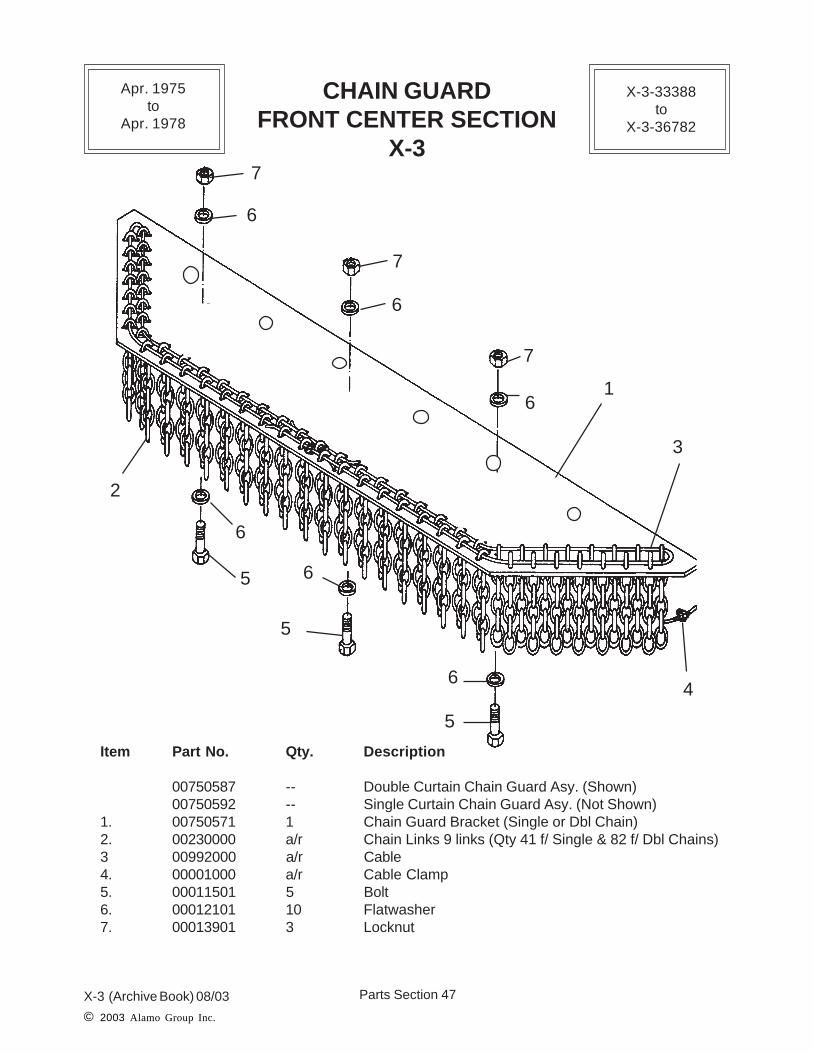
Item Part No. Qty. Description
00750587 -- Double Curtain Chain Guard Asy. (Shown)00750592 -- Single Curtain Chain Guard Asy. (Not Shown)
1. 00750571 1 Chain Guard Bracket (Single or Dbl Chain)2. 00230000 a/r Chain Links 9 links (Qty 41 f/ Single & 82 f/ Dbl Chains)3 00992000 a/r Cable4. 00001000 a/r Cable Clamp5. 00011501 5 Bolt6. 00012101 10 Flatwasher7. 00013901 3 Locknut
CHAIN GUARDFRONT CENTER SECTION
X-3
Apr. 1975to
Apr. 1978
X-3-33388to
X-3-36782
7
7
7
6
6
6
5
5
5
6
6
61
2
3
4

Parts Section 48X-3 (Archive Book) 08/03
© 2003 Alamo Group Inc.
CHAIN GUARDFRONT WING SECTION
X-3
Item Part No. Qty. Description
00750589 -- Double Curtain Chain Guard Asy. (Shown)00750594 -- Single Curtain Chain Guard Asy. (Not Shown)
1. 00750567 1 Chain Guard Bracket (Single or Dbl Chain)2. 0371200103 a/r Chain Links 9 links (Qty 45 f/ Single & 90 f/ Dbl Chains)3 00992000 a/r Cable4. 00001000 a/r Cable Clamp5. 02718900 5 Bolt6. 00019700 10 Flatwasher7. 05803901 5 Locknut8. 00022200 5 Lockwasher
Note: There are two of these used, one each front Wing Section, This Chain Guard Assembly willfit the RH or LH Wing. Qty above is for one Wing LH or RH Side.
Apr. 1975to
Apr. 1978
X-3-33388to
X-3-36782
1
2
3
4
5
6
78
6

Parts Section 49X-3 (Archive Book) 08/03
© 2003 Alamo Group Inc.
CHAIN GUARDREAR CENTER SECTION
X-3
Item Part No. Qty. Description00750588 -- Chain Guard Asy, Dble Curtain. (Shown)00750593 -- Chain Guard Asy, Single Curtain (Not Shown)
1. 00750566 1 Chain Guard Bracket, Center (Single or Dbl Chain)00750790 1 Chain Guard Supprt, RH Rear Center (Not Shown)00750791 1 Chain Guard Supprt, LH Rear Center (Not Shown)
2. 0371200103 a/r Chain Links 9 links (Qty 40 f/ Single & 79 f/ Dbl Chains)3. 00750543 4 Z Bar Support (Used on S/N X-3-34186 & Prior)
00750783 4 Z Bar Support (Used on S/N X-3-34187 & Later)4 00992000 a/r Cable5. 00001000 a/r Cable Clamp6. 00011501 16 Bolt7. 00012101 32 Flatwasher8. 00013901 16 Locknut9. 00022200 16 LockwasherNote: NLF = This Chain Guard used two side pieces with it # 00750894 double curtain or #00750893 single curtain (See Next Page). The above Chain Guard assemblies will be replaced by#00752274 double curtain and #00752275 single curtain. These replacemnt assemblies will notuse the two side assemblies at all.
Apr. 1975to
Apr. 1978
X-3-33388to
X-3-36782
1
2
3
4
5
67
7
7
7
6
9
98
8
4

Parts Section 50X-3 (Archive Book) 08/03
© 2003 Alamo Group Inc.
CHAIN GUARDREAR WING SECTION
X-3
Item Part No. Qty. Description
00750595 -- Rear Wing Chain Guard Set )Both Wings1. 00751237 1 Chain Guard Asy. Dble Chain, RH Wing
00751238 1 Chain Guard Asy. Dble Chain, LH Wing00751232 1 Chain Guard Asy. Sngl Chain, RH Wing00751233 1 Chain Guard Asy. Sngl Chain .LH Wing
1A. 00751213 1 Chain Guard Bracket RH Wing (Single or Dbl Chain)00751218 1 Chain Guard Bracket LH Wing (Single or Dbl Chain)
2. 0371200103 a/r Chain Links 9 links (Qty 26 f/ Single & 52 f/ Dbl Chains)3. 00750543 8 Z Bar Support (Used on S/N X-3-34186 & Prior)
00750783 8 Z Bar Support (Used on S/N X-3-34187 & Later)4 00992000 a/r Cable5. 00001000 a/r Cable Clamp6. 02718900 16 Bolt7. 00019700 32 Flatwasher8. 00022200 16 Lockwasher9. 05830901 16 Locknut10. 00750789 2 Rubber Flap (Not Shown)
Apr. 1975to
Apr. 1978
X-3-33388to
X-3-36782
1, 1A
4, 53
4, 5
2
67
89
7


X-3 Archive Manual 08/03
© 2003 Alamo Group Inc.
X-3 (Terrain King) Archive ManualProduction
Apr. 1975 (Start) S/N X-3-33388to Apr. 1978 (End) X-3-36782
Manual P/N 02980264
X-3 {