Embed Size (px)
Citation preview

Evergreen Turf Equipment, LLC • 1028 4th
St. SW, Bldg. A • Auburn, Washington 98001 • caltrimmer.com
Precision Reel Mowers
OPERATOR’S MANUAL
Models RL205 / RL207 RL255 / RL257
REEL MOWER OPERATOR’S MANUAL
Evergreen Turf Equipment, LLC • 1028 4th
St. SW, Bldg. A • Auburn, Washington 98001 • caltrimmer.com
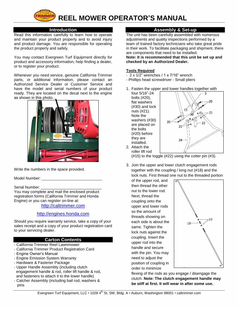
Introduction Read this information carefully to learn how to operate and maintain your product properly and to avoid injury and product damage. You are responsible for operating the product properly and safely. You may contact Evergreen Turf Equipment directly for product and accessory information, help finding a dealer, or to register your product. Whenever you need service, genuine California Trimmer parts, or additional information, please contact an Authorized Service Dealer or Customer Service and have the model and serial numbers of your product ready. They are located on the decal next to the engine as shown in this photo…
Write the numbers in the space provided. Model Number: ____________________________ Serial Number: ____________________________ You may complete and mail the enclosed product registration forms (California Trimmer and Honda Engine) or you can register on-line at:
http://caltrimmer.com
http://engines.honda.com
Should you require warranty service, take a copy of your sales receipt and a copy of your product registration card to your servicing dealer.
Carton Contents - California Trimmer Reel Lawnmower - California Trimmer Product Registration Card - Engine Owner’s Manual - Engine Emission System Warranty - Hardware & Fastener Package - Upper Handle Assembly (including clutch engagement handle & rod, roller lift handle & rod, and fasteners to attach it to the lower handle) - Catcher Assembly (including bail rod, washers & pins
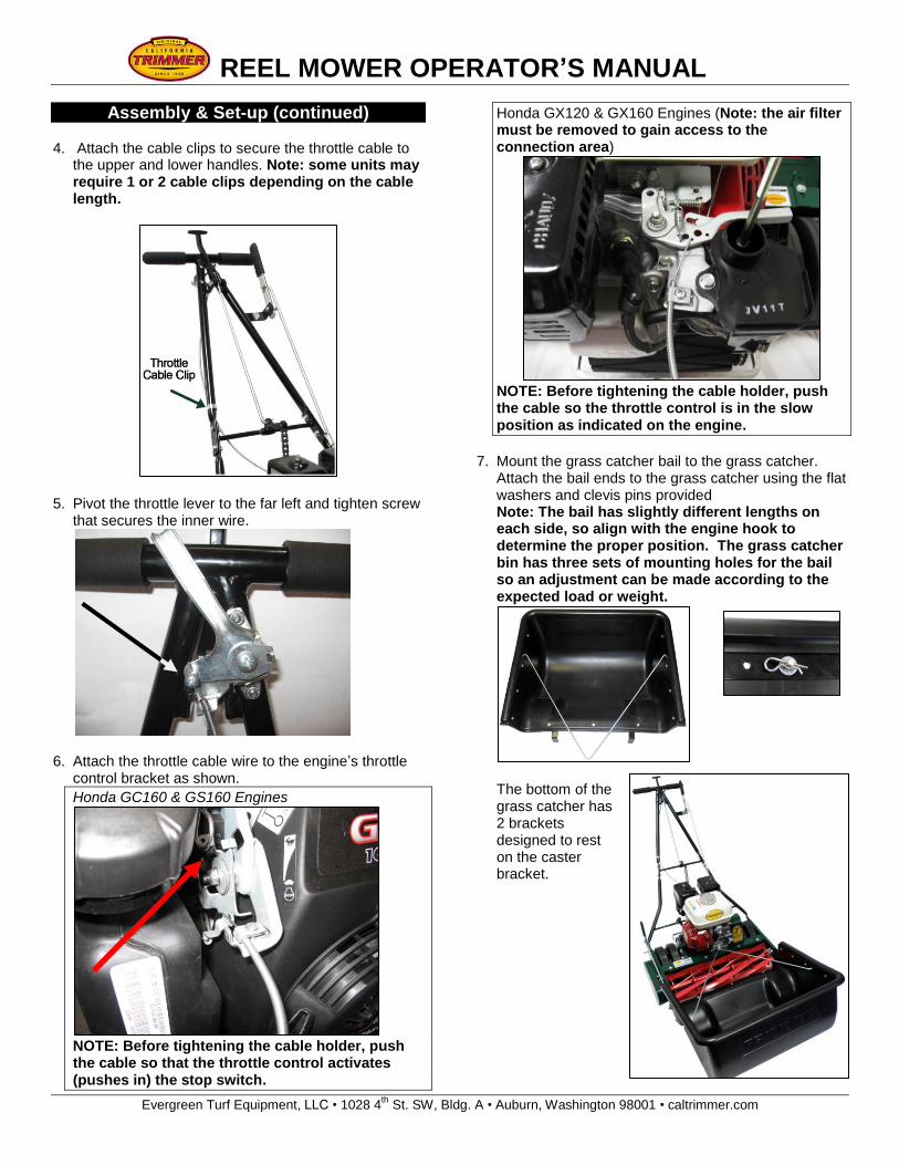
Assembly & Set-up The unit has been carefully assembled with numerous adjustments and quality inspections performed by a team of trained factory technicians who take great pride in their work. To facilitate packaging and shipment, there are components that need to be installed. Note: It is recommended that this unit be set up and checked by an Authorized Dealer. Tools Required - 2 x 1/2” wrenches / 1 x 7/16” wrench - Phillips head screwdriver - Small pliers 1. Fasten the upper and lower handles together with
four 5/16”-24 bolts (#20), flat washers (#30) and lock nuts (#21). Note the washers (#30) are placed on the bolts (#20) before they are installed.
2. Attach the roller lift rod (#15) to the toggle (#22) using the cotter pin (#3).
3. Join the upper and lower clutch engagement rods
together with the coupling / long nut (#18) and the
lock nuts. First thread one nut to the threaded portion
of the upper rod, and
then thread the other
nut to the lower rod.
Next, thread the
coupling onto the
upper and lower rods
so the amount of
threads showing on
each side is about the
same. Tighten the
lock nuts against the
coupling. Insert the
upper rod into the
handle and secure
with the pin. You may
need to adjust the
position of coupling in
order to minimize
flexing of the rods as you engage / disengage the
clutch. Note: The clutch engagement handle may
be stiff at first. It will wear in after some use.
REEL MOWER OPERATOR’S MANUAL
Evergreen Turf Equipment, LLC • 1028 4th
St. SW, Bldg. A • Auburn, Washington 98001 • caltrimmer.com
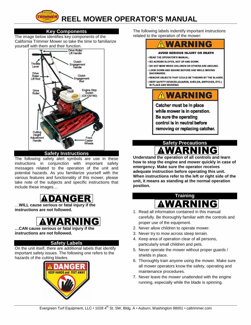
Assembly & Set-up (continued) 4. Attach the cable clips to secure the throttle cable to
the upper and lower handles. Note: some units may require 1 or 2 cable clips depending on the cable length.
5. Pivot the throttle lever to the far left and tighten screw
that secures the inner wire.
6. Attach the throttle cable wire to the engine’s throttle
control bracket as shown.
Honda GC160 & GS160 Engines
NOTE: Before tightening the cable holder, push the cable so that the throttle control activates (pushes in) the stop switch.
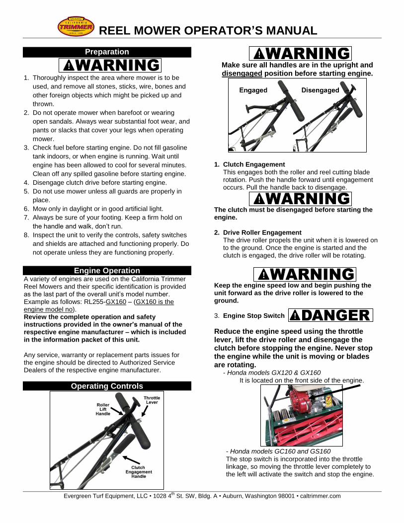
Honda GX120 & GX160 Engines (Note: the air filter must be removed to gain access to the connection area)
NOTE: Before tightening the cable holder, push the cable so the throttle control is in the slow position as indicated on the engine.
7. Mount the grass catcher bail to the grass catcher.
Attach the bail ends to the grass catcher using the flat washers and clevis pins provided Note: The bail has slightly different lengths on each side, so align with the engine hook to determine the proper position. The grass catcher bin has three sets of mounting holes for the bail so an adjustment can be made according to the expected load or weight.
The bottom of the grass catcher has 2 brackets designed to rest on the caster bracket.
REEL MOWER OPERATOR’S MANUAL
Evergreen Turf Equipment, LLC • 1028 4th
St. SW, Bldg. A • Auburn, Washington 98001 • caltrimmer.com
Key Components The image below identifies key components of the California Trimmer Mower so take the time to familiarize yourself with them and their function.
Safety Instructions
The following safety alert symbols are use in these instructions in conjunction with important safety messages related to the operation of the unit and potential hazards. As you familiarize yourself with the various features and functionality of this mower, please take note of the subjects and specific instructions that include these images…
…WILL cause serious or fatal injury if the instructions are not followed.
…CAN cause serious or fatal injury if the instructions are not followed.
Safety Labels On the unit itself, there are additional labels that identify important safety issues. The following one refers to the hazards of the cutting blades.
The following labels indentify important instructions related to the operation of the mower:
Safety Precautions
Understand the operation of all controls and learn how to stop the engine and mower quickly in case of emergency. Make sure the operator receives adequate instruction before operating this unit. When instructions refer to the left or right side of the unit, it means as standing at the normal operation position.
Training
1. Read all information contained in this manual
carefully. Be thoroughly familiar with the controls and
proper use of the equipment.
2. Never allow children to operate mower.
3. Never try to mow across steep terrain.
4. Keep area of operation clear of all persons,
particularly small children and pets.
5. Never operate the mower without proper guards /
shields in place.
6. Thoroughly train anyone using the mower. Make sure
all mower operators know the safety, operating and
maintenance procedures.
7. Never leave the mower unattended with the engine
running, especially while the blade is spinning.
REEL MOWER OPERATOR’S MANUAL
Evergreen Turf Equipment, LLC • 1028 4th
St. SW, Bldg. A • Auburn, Washington 98001 • caltrimmer.com
Preparation
1. Thoroughly inspect the area where mower is to be
used, and remove all stones, sticks, wire, bones and
other foreign objects which might be picked up and
thrown.
2. Do not operate mower when barefoot or wearing
open sandals. Always wear substantial foot wear, and
pants or slacks that cover your legs when operating
mower.
3. Check fuel before starting engine. Do not fill gasoline
tank indoors, or when engine is running. Wait until
engine has been allowed to cool for several minutes.
Clean off any spilled gasoline before starting engine.
4. Disengage clutch drive before starting engine.
5. Do not use mower unless all guards are properly in
place.
6. Mow only in daylight or in good artificial light.
7. Always be sure of your footing. Keep a firm hold on
the handle and walk, don’t run.
8. Inspect the unit to verify the controls, safety switches
and shields are attached and functioning properly. Do
not operate unless they are functioning properly.
Engine Operation A variety of engines are used on the California Trimmer Reel Mowers and their specific identification is provided as the last part of the overall unit’s model number. Example as follows: RL255-GX160 – (GX160 is the engine model no). Review the complete operation and safety instructions provided in the owner’s manual of the respective engine manufacturer – which is included in the information packet of this unit. Any service, warranty or replacement parts issues for the engine should be directed to Authorized Service Dealers of the respective engine manufacturer.
Operating Controls
Make sure all handles are in the upright and disengaged position before starting engine.
1. Clutch Engagement This engages both the roller and reel cutting blade rotation. Push the handle forward until engagement occurs. Pull the handle back to disengage.
The clutch must be disengaged before starting the engine. 2. Drive Roller Engagement
The drive roller propels the unit when it is lowered on to the ground. Once the engine is started and the clutch is engaged, the drive roller will be rotating.
Keep the engine speed low and begin pushing the unit forward as the drive roller is lowered to the ground.
3. Engine Stop Switch
Reduce the engine speed using the throttle lever, lift the drive roller and disengage the clutch before stopping the engine. Never stop the engine while the unit is moving or blades are rotating.
- Honda models GX120 & GX160 It is located on the front side of the engine.
- Honda models GC160 and GS160 The stop switch is incorporated into the throttle linkage, so moving the throttle lever completely to the left will activate the switch and stop the engine.
REEL MOWER OPERATOR’S MANUAL
Evergreen Turf Equipment, LLC • 1028 4th
St. SW, Bldg. A • Auburn, Washington 98001 • caltrimmer.com
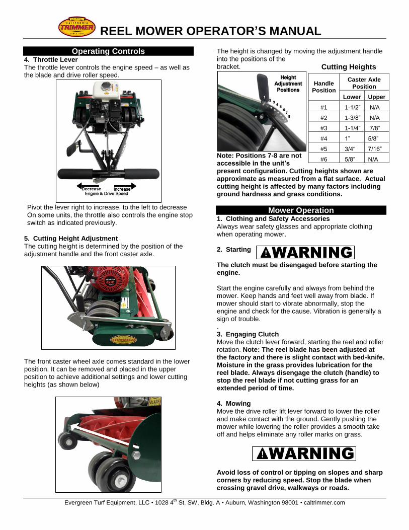
Operating Controls 4. Throttle Lever The throttle lever controls the engine speed – as well as the blade and drive roller speed.
Pivot the lever right to increase, to the left to decrease On some units, the throttle also controls the engine stop switch as indicated previously.
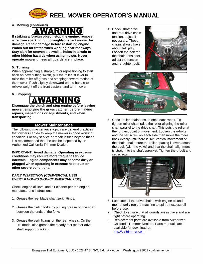
5. Cutting Height Adjustment The cutting height is determined by the position of the adjustment handle and the front caster axle.
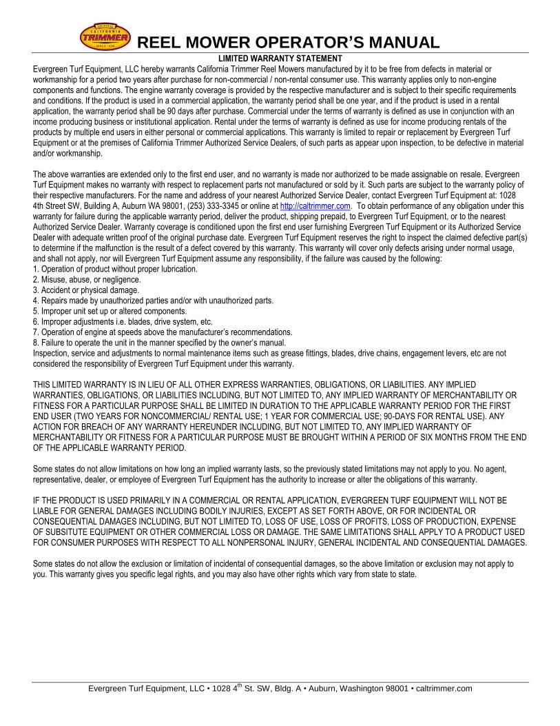
The front caster wheel axle comes standard in the lower position. It can be removed and placed in the upper position to achieve additional settings and lower cutting heights (as shown below)
The height is changed by moving the adjustment handle into the positions of the bracket.
Note: Positions 7-8 are not accessible in the unit’s present configuration. Cutting heights shown are approximate as measured from a flat surface. Actual cutting height is affected by many factors including ground hardness and grass conditions.
Mower Operation 1. Clothing and Safety Accessories Always wear safety glasses and appropriate clothing when operating mower. 2. Starting
The clutch must be disengaged before starting the engine. Start the engine carefully and always from behind the mower. Keep hands and feet well away from blade. If mower should start to vibrate abnormally, stop the engine and check for the cause. Vibration is generally a sign of trouble. . 3. Engaging Clutch Move the clutch lever forward, starting the reel and roller rotation. Note: The reel blade has been adjusted at the factory and there is slight contact with bed-knife. Moisture in the grass provides lubrication for the reel blade. Always disengage the clutch (handle) to stop the reel blade if not cutting grass for an extended period of time. 4. Mowing Move the drive roller lift lever forward to lower the roller and make contact with the ground. Gently pushing the mower while lowering the roller provides a smooth take off and helps eliminate any roller marks on grass.
Avoid loss of control or tipping on slopes and sharp corners by reducing speed. Stop the blade when crossing gravel drive, walkways or roads.
Cutting Heights
Handle Position
Caster Axle Position
Lower Upper
#1 1-1/2” N/A
#2 1-3/8” N/A
#3 1-1/4” 7/8”
#4 1” 5/8”
#5 3/4" 7/16”
#6 5/8” N/A
REEL MOWER OPERATOR’S MANUAL
Evergreen Turf Equipment, LLC • 1028 4th
St. SW, Bldg. A • Auburn, Washington 98001 • caltrimmer.com
4. Mowing (continued)
If striking a foreign object, stop the engine, remove wire from spark plug, thoroughly inspect mower for damage. Repair damage before restarting engine. Watch out for traffic when working near roadways. Stay alert for uneven sidewalks, holes in terrain or other hidden hazards when using mower. Never operate mower unless all guards are in place.
5. Turning When approaching a sharp turn or repositioning to start back on next cutting swath, pull the roller lift lever to raise the roller off grass and stopping forward motion of the mower. Push slightly downward on the handle to relieve weight off the front casters, and turn mower.
6. Stopping
Disengage the clutch and stop engine before leaving mower, emptying the grass catcher, before making repairs, inspections or adjustments, and when transporting.
Mower Maintenance The following maintenance topics are general practices that owners can do to keep the mower in good working condition. For any service or repair issues beyond these, it is recommended that the unit be inspected by an Authorized California Trimmer Dealer. IMPORTANT: Avoid damage! Operating in extreme conditions may require more frequent service intervals. Engine components may become dirty or plugged when operating in extreme heat, dust or other severe conditions. DAILY INSPECTION (COMMERCIAL USE) EVERY 8 HOURS (NON-COMMERCIAL USE) Check engine oil level and air cleaner per the engine manufacturer’s instructions. 1. Grease the reel blade shaft zerk fittings.
2. Grease the clutch forks by putting grease on the shaft
between the ends of the forks
3. Grease the zerk fittings on the rear wheels. On the
25" model also grease the steady rest (center drive
shaft support bracket)
4. Check shaft drive and reel drive chain tension, adjust if necessary. These chains should have about 1/4" play. Loosen the bolt for the chain tensioner, adjust the tension and re-tighten bolt.
5. Check roller chain tension once each week. To tighten roller chain raise the roller aligning the roller shaft parallel to the drive shaft. This puts the roller at the furthest point of movement. Loosen the u-bolts and the set screw on each side then move the roller back evenly until there is 1/2” vertical movement of the chain. Make sure the roller spacing is even across the back (with the yoke) and that the chain alignment is straight to the shaft sprocket. Tighten the u-bolt and set screws.
6. Lubricate all the drive chains with engine oil and
momentarily run the machine to spin off excess oil before use.
7. Check to ensure that all guards are in place and are tight before operating.
8. Replacement parts are available from Authorized California Trimmer Dealers. Parts manuals are available for download at: http://caltrimmer.com
REEL MOWER OPERATOR’S MANUAL
Evergreen Turf Equipment, LLC • 1028 4th
St. SW, Bldg. A • Auburn, Washington 98001 • caltrimmer.com
LIMITED WARRANTY STATEMENT Evergreen Turf Equipment, LLC hereby warrants California Trimmer Reel Mowers manufactured by it to be free from defects in material or workmanship for a period two years after purchase for non-commercial / non-rental consumer use. This warranty applies only to non-engine components and functions. The engine warranty coverage is provided by the respective manufacturer and is subject to their specific requirements and conditions. If the product is used in a commercial application, the warranty period shall be one year, and if the product is used in a rental application, the warranty period shall be 90 days after purchase. Commercial under the terms of warranty is defined as use in conjunction with an income producing business or institutional application. Rental under the terms of warranty is defined as use for income producing rentals of the products by multiple end users in either personal or commercial applications. This warranty is limited to repair or replacement by Evergreen Turf Equipment or at the premises of California Trimmer Authorized Service Dealers, of such parts as appear upon inspection, to be defective in material and/or workmanship. The above warranties are extended only to the first end user, and no warranty is made nor authorized to be made assignable on resale. Evergreen Turf Equipment makes no warranty with respect to replacement parts not manufactured or sold by it. Such parts are subject to the warranty policy of their respective manufacturers. For the name and address of your nearest Authorized Service Dealer, contact Evergreen Turf Equipment at: 1028 4th Street SW, Building A, Auburn WA 98001, (253) 333-3345 or online at http://caltrimmer.com. To obtain performance of any obligation under this warranty for failure during the applicable warranty period, deliver the product, shipping prepaid, to Evergreen Turf Equipment, or to the nearest Authorized Service Dealer. Warranty coverage is conditioned upon the first end user furnishing Evergreen Turf Equipment or its Authorized Service Dealer with adequate written proof of the original purchase date. Evergreen Turf Equipment reserves the right to inspect the claimed defective part(s) to determine if the malfunction is the result of a defect covered by this warranty. This warranty will cover only defects arising under normal usage, and shall not apply, nor will Evergreen Turf Equipment assume any responsibility, if the failure was caused by the following: 1. Operation of product without proper lubrication. 2. Misuse, abuse, or negligence. 3. Accident or physical damage. 4. Repairs made by unauthorized parties and/or with unauthorized parts. 5. Improper unit set up or altered components. 6. Improper adjustments i.e. blades, drive system, etc. 7. Operation of engine at speeds above the manufacturer’s recommendations. 8. Failure to operate the unit in the manner specified by the owner’s manual. Inspection, service and adjustments to normal maintenance items such as grease fittings, blades, drive chains, engagement levers, etc are not considered the responsibility of Evergreen Turf Equipment under this warranty. THIS LIMITED WARRANTY IS IN LIEU OF ALL OTHER EXPRESS WARRANTIES, OBLIGATIONS, OR LIABILITIES. ANY IMPLIED WARRANTIES, OBLIGATIONS, OR LIABILITIES INCLUDING, BUT NOT LIMITED TO, ANY IMPLIED WARRANTY OF MERCHANTABILITY OR FITNESS FOR A PARTICULAR PURPOSE SHALL BE LIMITED IN DURATION TO THE APPLICABLE WARRANTY PERIOD FOR THE FIRST END USER (TWO YEARS FOR NONCOMMERCIAL/ RENTAL USE; 1 YEAR FOR COMMERCIAL USE; 90-DAYS FOR RENTAL USE). ANY ACTION FOR BREACH OF ANY WARRANTY HEREUNDER INCLUDING, BUT NOT LIMITED TO, ANY IMPLIED WARRANTY OF MERCHANTABILITY OR FITNESS FOR A PARTICULAR PURPOSE MUST BE BROUGHT WITHIN A PERIOD OF SIX MONTHS FROM THE END OF THE APPLICABLE WARRANTY PERIOD. Some states do not allow limitations on how long an implied warranty lasts, so the previously stated limitations may not apply to you. No agent, representative, dealer, or employee of Evergreen Turf Equipment has the authority to increase or alter the obligations of this warranty. IF THE PRODUCT IS USED PRIMARILY IN A COMMERCIAL OR RENTAL APPLICATION, EVERGREEN TURF EQUIPMENT WILL NOT BE LIABLE FOR GENERAL DAMAGES INCLUDING BODILY INJURIES, EXCEPT AS SET FORTH ABOVE, OR FOR INCIDENTAL OR CONSEQUENTIAL DAMAGES INCLUDING, BUT NOT LIMITED TO, LOSS OF USE, LOSS OF PROFITS, LOSS OF PRODUCTION, EXPENSE OF SUBSITUTE EQUIPMENT OR OTHER COMMERCIAL LOSS OR DAMAGE. THE SAME LIMITATIONS SHALL APPLY TO A PRODUCT USED FOR CONSUMER PURPOSES WITH RESPECT TO ALL NONPERSONAL INJURY, GENERAL INCIDENTAL AND CONSEQUENTIAL DAMAGES. Some states do not allow the exclusion or limitation of incidental of consequential damages, so the above limitation or exclusion may not apply to you. This warranty gives you specific legal rights, and you may also have other rights which vary from state to state.