Embed Size (px)
Citation preview
Engineering drawingEngineering drawing
Semester I/IISemester I/II
Mechanical Engineering DepartmentMechanical Engineering Department
Technical University of GdaTechnical University of Gdańńsksk
Lecture Lecture 88
Representing Tolerance ValuesRepresenting Tolerance Values
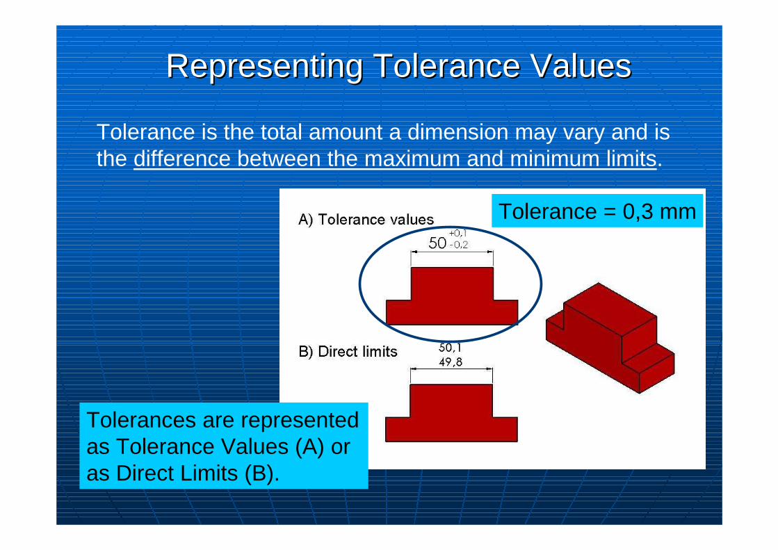
Tolerance is the total amount a dimension may vary and is the difference between the maximum and minimum limits.
Tolerance = 0,3 mm
Tolerances are represented as Tolerance Values (A) or as Direct Limits (B).
Important Terms of Toleranced PartsImportant Terms of Toleranced Parts
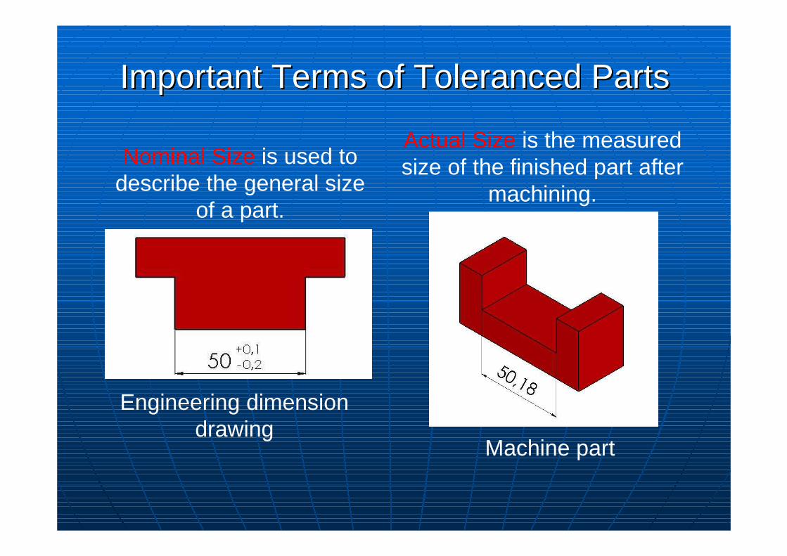
Nominal Size is used to describe the general size
of a part.
Actual Size is the measured size of the finished part after
machining.
Machine part
Engineering dimension drawing
Important Terms of Toleranced PartsImportant Terms of Toleranced Parts
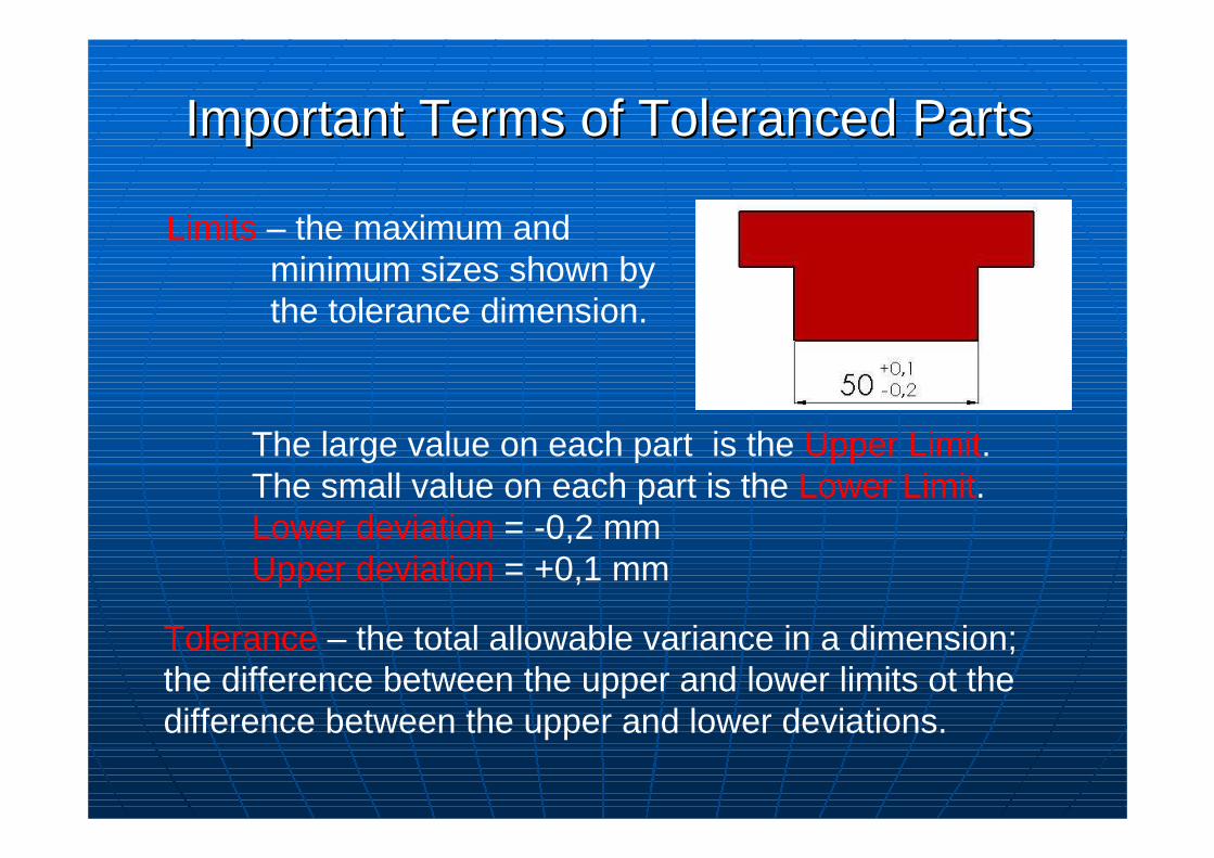
Limits – the maximum and minimum sizes shown by the tolerance dimension.
Tolerance – the total allowable variance in a dimension;the difference between the upper and lower limits ot the difference between the upper and lower deviations.
The large value on each part is the Upper Limit.The small value on each part is the Lower Limit.Lower deviation = -0,2 mmUpper deviation = +0,1 mm
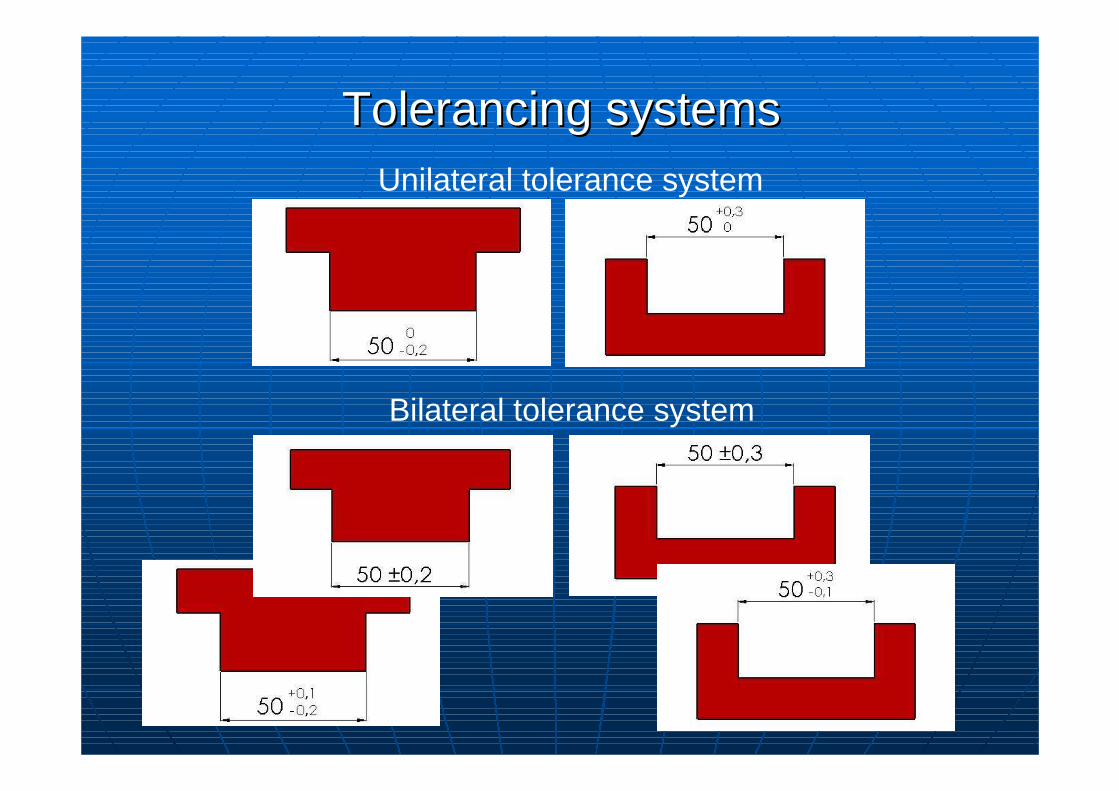
Tolerancing systemsTolerancing systemsUnilateral tolerance system
Bilateral tolerance system
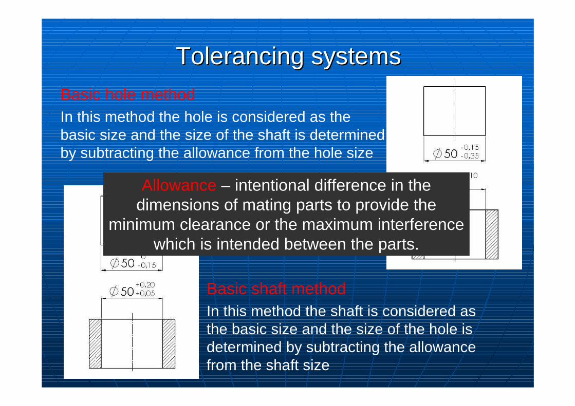
Tolerancing systemsTolerancing systems
Basic hole methodIn this method the hole is considered as the basic size and the size of the shaft is determined by subtracting the allowance from the hole size
Basic shaft methodIn this method the shaft is considered as the basic size and the size of the hole is determined by subtracting the allowance from the shaft size
Allowance – intentional difference in the dimensions of mating parts to provide the
minimum clearance or the maximum interference which is intended between the parts.
ISO Tolerance DesignationISO Tolerance DesignationThe ISO system provides for:• 21 types of holes (standard tolerances) designated by
uppercase letters A, B, C, D, E....etc. and• 21 types of shafts designated by the lower case letters a,
b, c, d, e...etc.These letters define the position of the tolerance zone relative to the nominal size. To each of these types of hole or shaft are applied 16 grades of tolerance, designated by numbers IT1 to IT16.
Example:A hole is specified as: ø30 H7
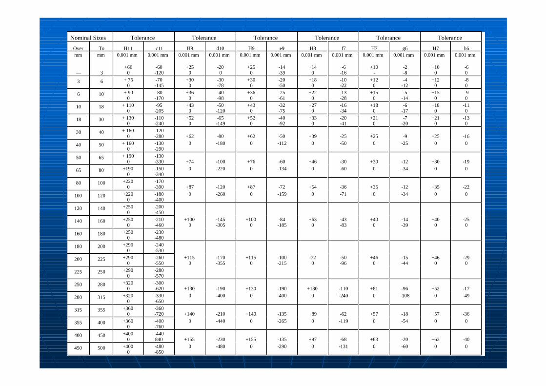
Nominal Sizes Tolerance Tolerance Tolerance Tolerance Tolerance Tolerance
Over To H11 c11 H9 d10 H9 e9 H8 f7 H7 g6 H7 h6mm
––
mm
3
0.001 mm
+600
0.001 mm
-60-120
0.001 mm
+250
0.001 mm
-200
0.001 mm
+250
0.001 mm
-14-39
0.001 mm
+140
0.001 mm
-6-16
0.001 mm
+10-
0.001 mm
-2-8
0.001 mm
+100
0.001 mm
-60
3 6 + 750
-70-145
+300
-30-78
+300
-20-50
+180
-10-22
+120
-4-12
+120
-80
6 10 + 900
-80-170
+360
-40-98
+360
-25-61
+220
-13-28
+150
-5-14
+150
-90
10 18 + 1100
-95-205
+430
-50-120
+430
-32-75
+270
-16-34
+180
-6-17
+180
-110
18 30 + 1300
-110-240
+520
-65-149
+520
-40-92
+330
-20-41
+210
-7-20
+210
-130
30 40 + 1600
-120-280 +62 -80 +62 -50 +39 -25 +25 -9 +25 -16
40 50 + 1600
-130-290
0 -180 0 -112 0 -50 0 -25 0 0
50 65 + 1900
-130-330 +74 -100 +76 -60 +46 -30 +30 -12 +30 -19
65 80 +1900
-150-340
0 -220 0 -134 0 -60 0 -34 0 0
80 100 +2200
-170-390 +87 -120 +87 -72 +54 -36 +35 -12 +35 -22
100 120 +2200
-180-400
0 -260 0 -159 0 -71 0 -34 0 0
120 140 +2500
-200-450
140 160 +2500
-210-460
+1000
-145-305
+1000
-84-185
+630
-43-83
+400
-14-39
+400
-250
160 180 +2500
-230-480
180 200 +2900
-240-530
200 225 +2900
-260-550
+1150
-170-355
+1150
-100-215
-720
-50-96
+460
-15-44
+460
-290
225 250 +2900
-280-570
250 280 +3200
-300-620 +130 -190 +130 -190 +130 -110 +81 -96 +52 -17
280 315 +3200
-330-650
0 -400 0 -400 0 -240 0 -108 0 -49
315 355 +3600
-360-720 +140 -210 +140 -135 +89 -62 +57 -18 +57 -36
355 400 +3600
-400-760
0 -440 0 -265 0 -119 0 -54 0 0
400 450 +4000
-440840 +155 -230 +155 -135 +97 -68 +63 -20 +63 -40
450 500 +4000
-480-850
0 -480 0 -290 0 -131 0 -60 0 0
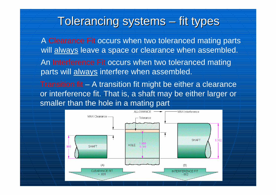
A Clearance Fit occurs when two toleranced mating parts will always leave a space or clearance when assembled.
An Interference Fit occurs when two toleranced mating parts will always interfere when assembled.
Tolerancing systems Tolerancing systems –– fit typesfit types
Transition fit – A transition fit might be either a clearance or interference fit. That is, a shaft may be either larger or smaller than the hole in a mating part
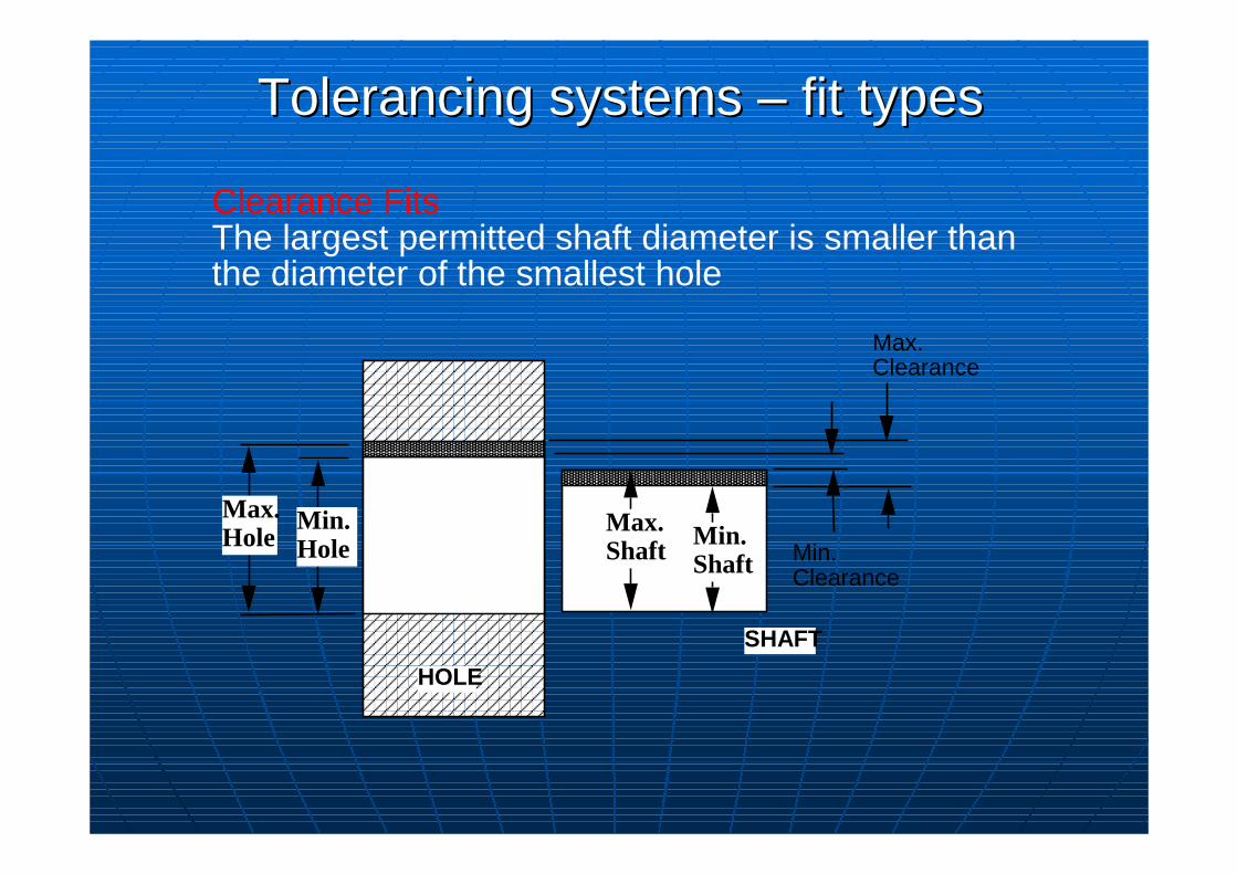
Clearance FitsThe largest permitted shaft diameter is smaller than the diameter of the smallest hole
Min. Hole
Max. Hole
HOLE
SHAFT
Max. Clearance
Min. Clearance
Min. Shaft
Max. Shaft
Tolerancing systems Tolerancing systems –– fit typesfit types
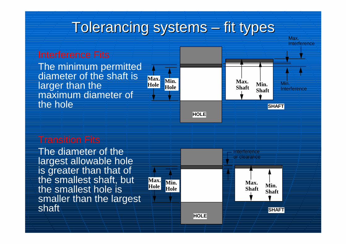
Interference FitsThe minimum permitted diameter of the shaft is larger than the maximum diameter of the hole
Transition FitsThe diameter of the largest allowable hole is greater than that of the smallest shaft, but the smallest hole is smaller than the largest shaft
Min. Hole
Max. Hole
HOLE
SHAFT
Max. Interference
Min. Interference
Min. Shaft
Max. Shaft
Min. Hole
Max. Hole
HOLESHAFT
Interference or clearance
Min. Shaft
Max. Shaft
Tolerancing systems Tolerancing systems –– fit typesfit types
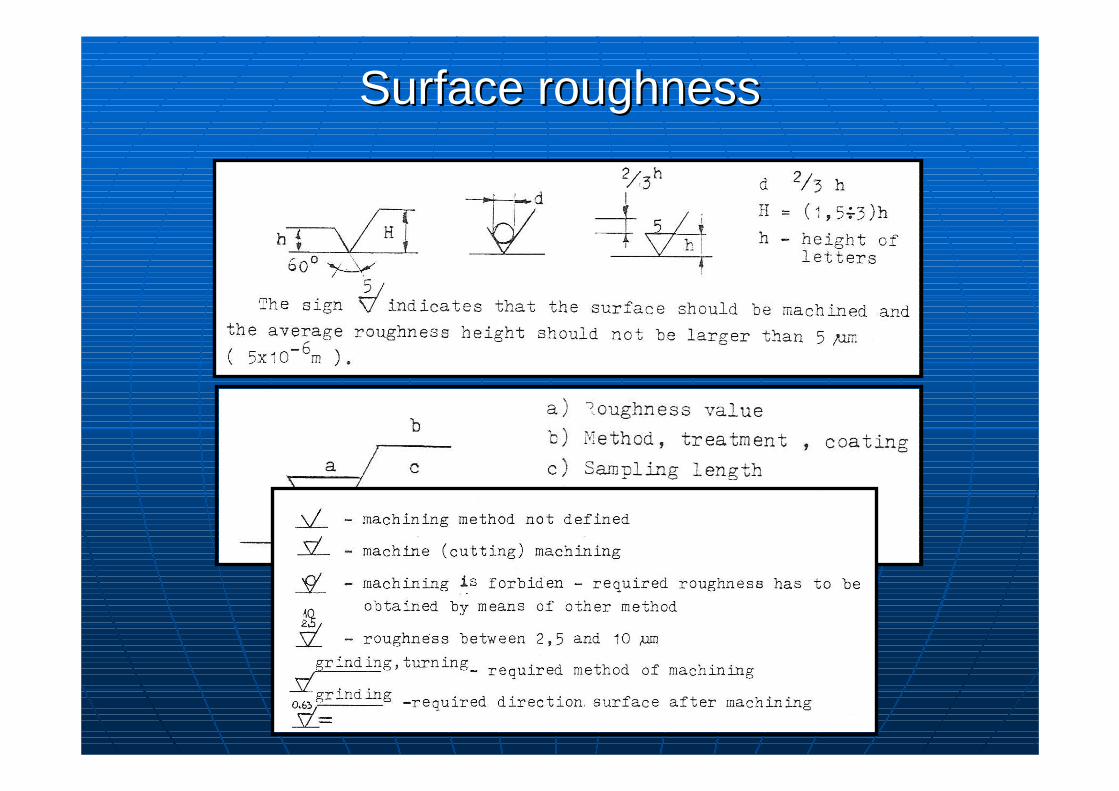
Surface roughnessSurface roughness
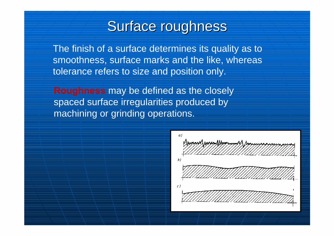
The finish of a surface determines its quality as to smoothness, surface marks and the like, whereas tolerance refers to size and position only.
Roughness may be defined as the closely spaced surface irregularities produced by machining or grinding operations.
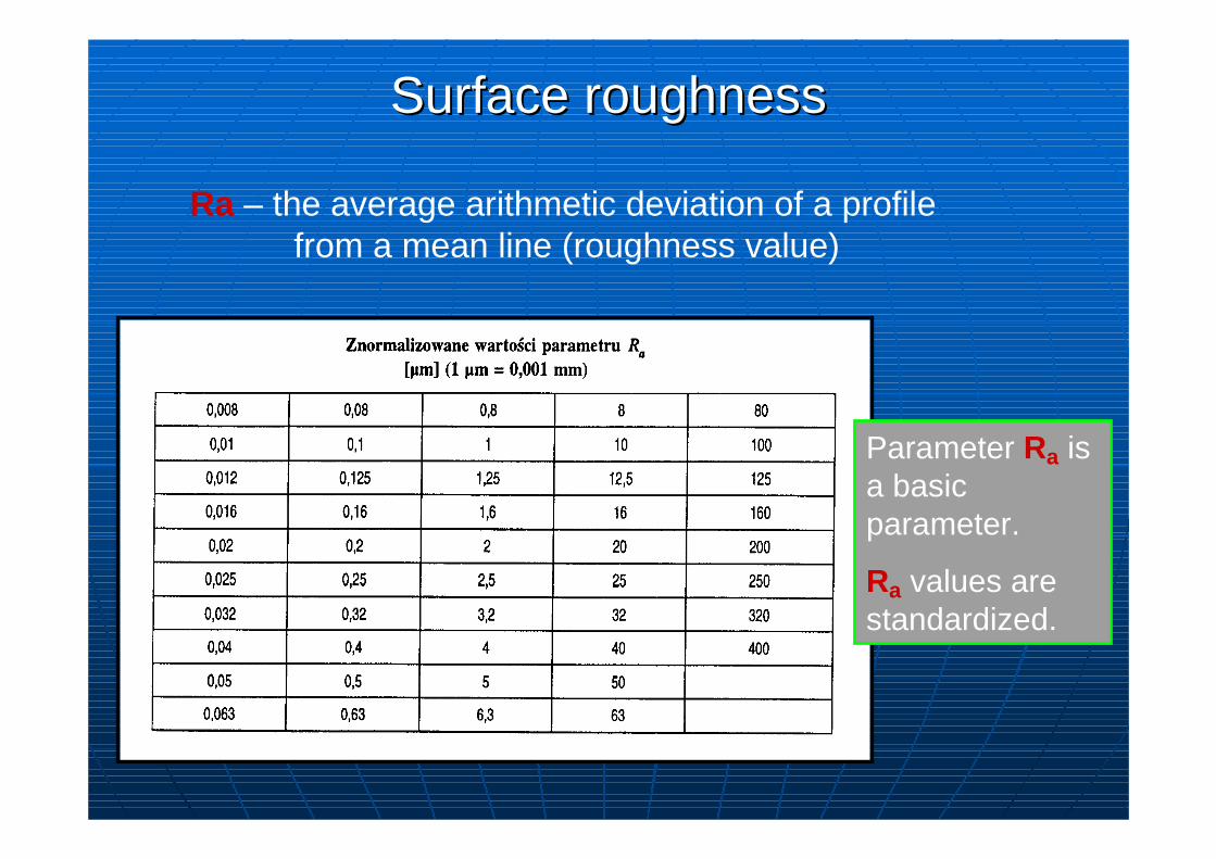
Ra – the average arithmetic deviation of a profile from a mean line (roughness value)
Surface roughnessSurface roughness
Parameter Ra is a basic parameter.
Ra values are standardized.
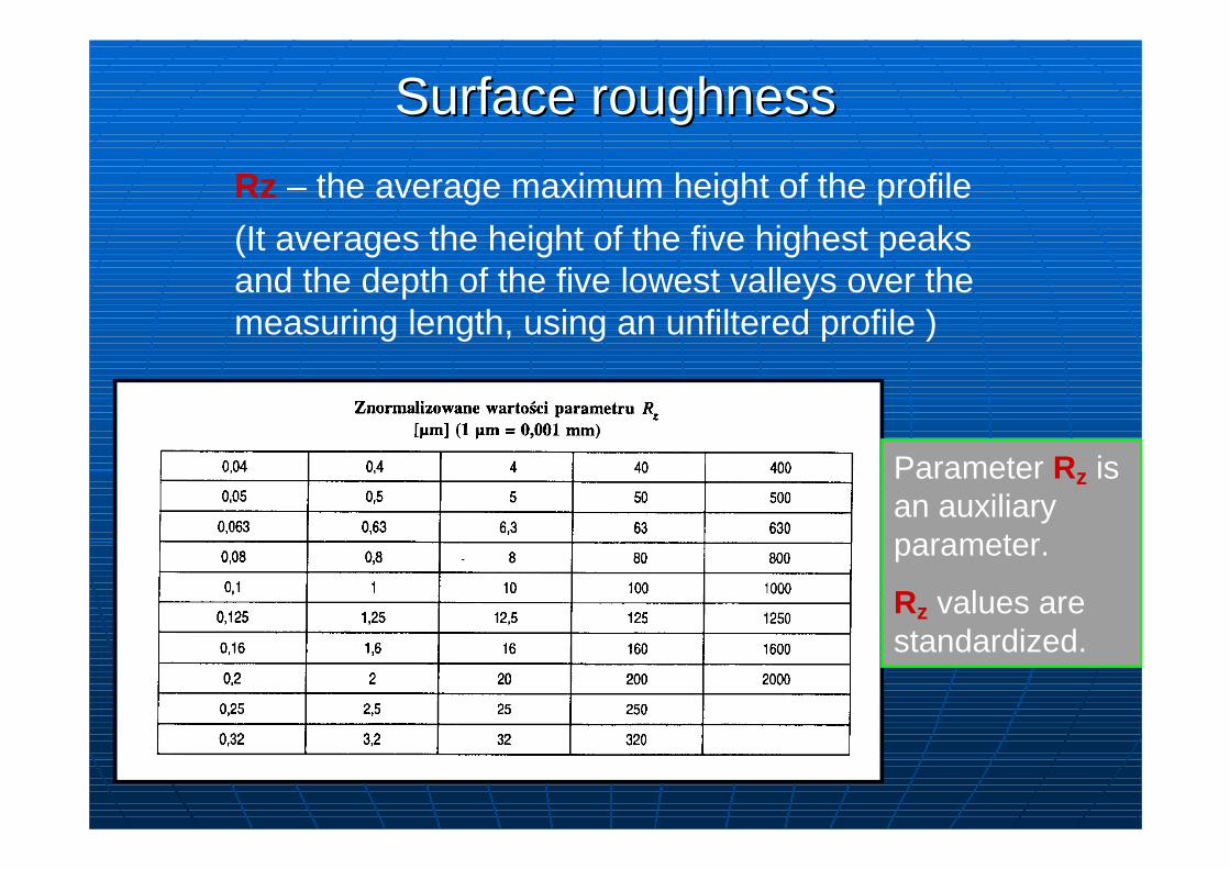
Parameter Rz is an auxiliary parameter.
Rz values are standardized.
Surface roughnessSurface roughness
Rz – the average maximum height of the profile
(It averages the height of the five highest peaks and the depth of the five lowest valleys over the measuring length, using an unfiltered profile )
Surface roughnessSurface roughness
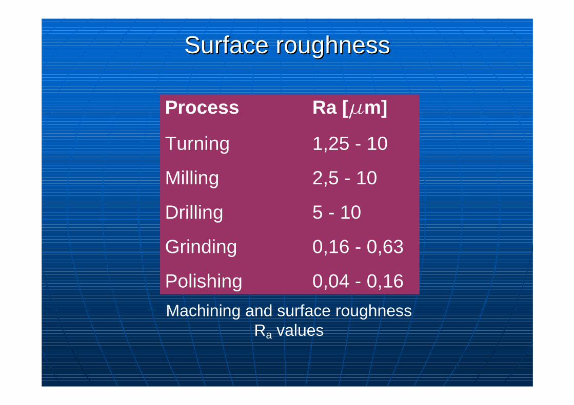
Process Ra [ mmmmm]
Turning 1,25 - 10
Milling 2,5 - 10
Drilling 5 - 10
Grinding 0,16 - 0,63
Polishing 0,04 - 0,16
Surface roughnessSurface roughness
Machining and surface roughness Ra values
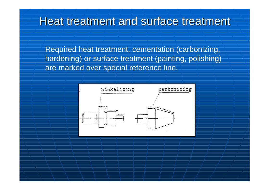
Heat treatment and surface treatmentHeat treatment and surface treatment
Required heat treatment, cementation (carbonizing, hardening) or surface treatment (painting, polishing) are marked over special reference line.
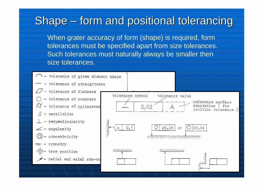
Shape Shape –– form and positional tolerancingform and positional tolerancingWhen grater accuracy of form (shape) is required, form tolerances must be specified apart from size tolerances. Such tolerances must naturally always be smaller then size tolerances.
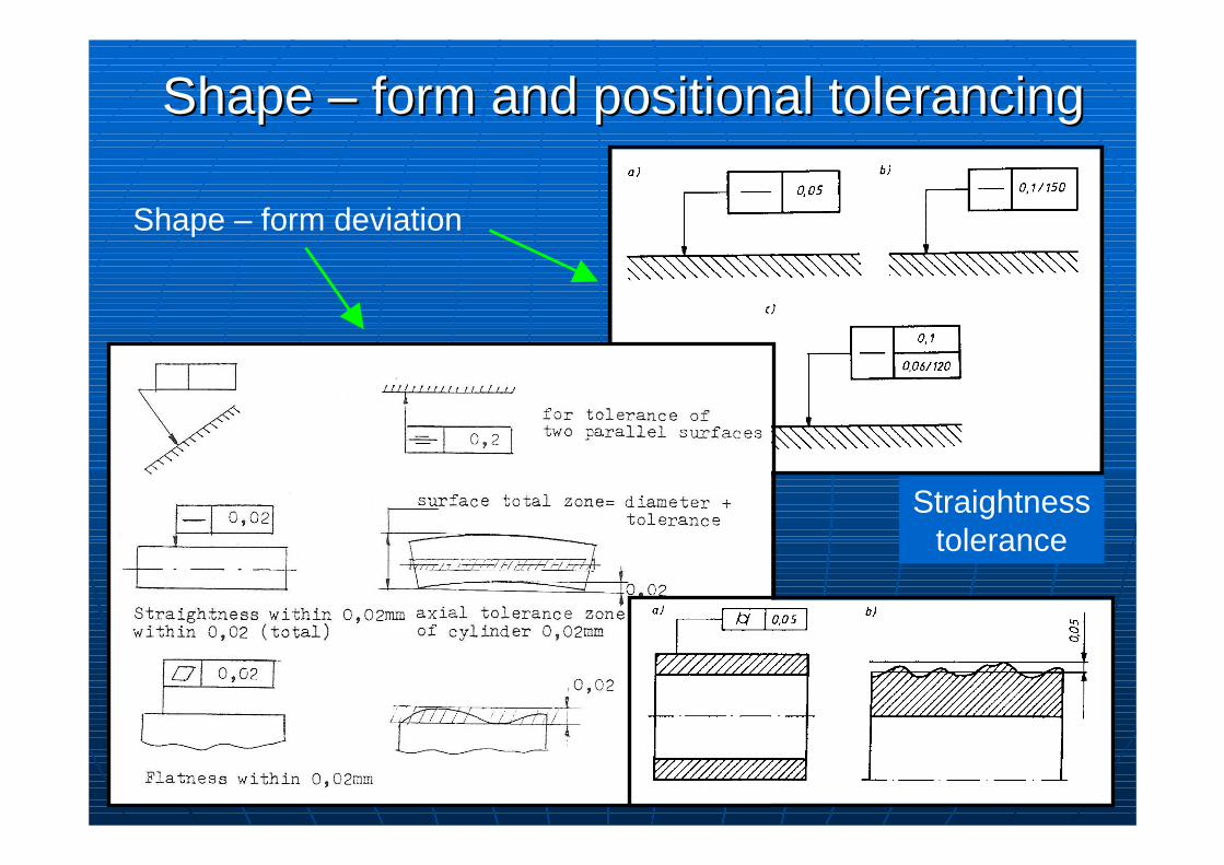
Shape – form deviation
Straightness tolerance
Shape Shape –– form and positional tolerancingform and positional tolerancing
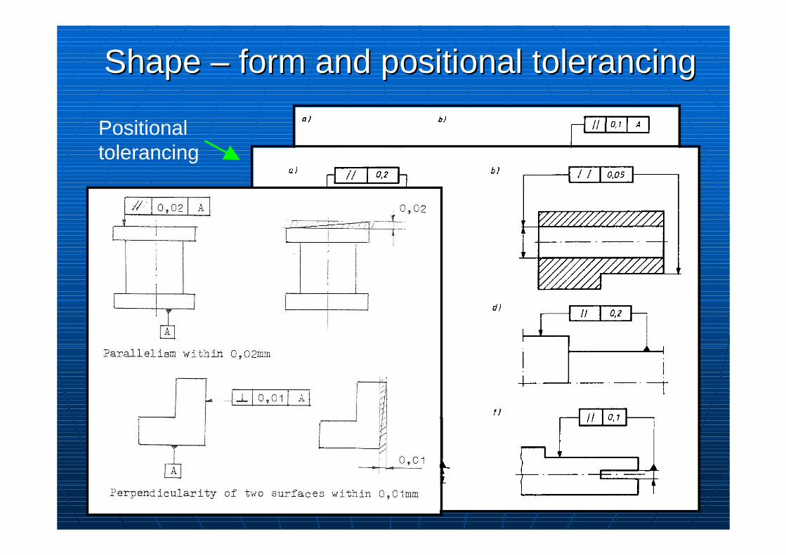
Positional tolerancing
Shape Shape –– form and positional tolerancingform and positional tolerancing
Tolerancja rTolerancja r óównolegwnoleg łłoośścici
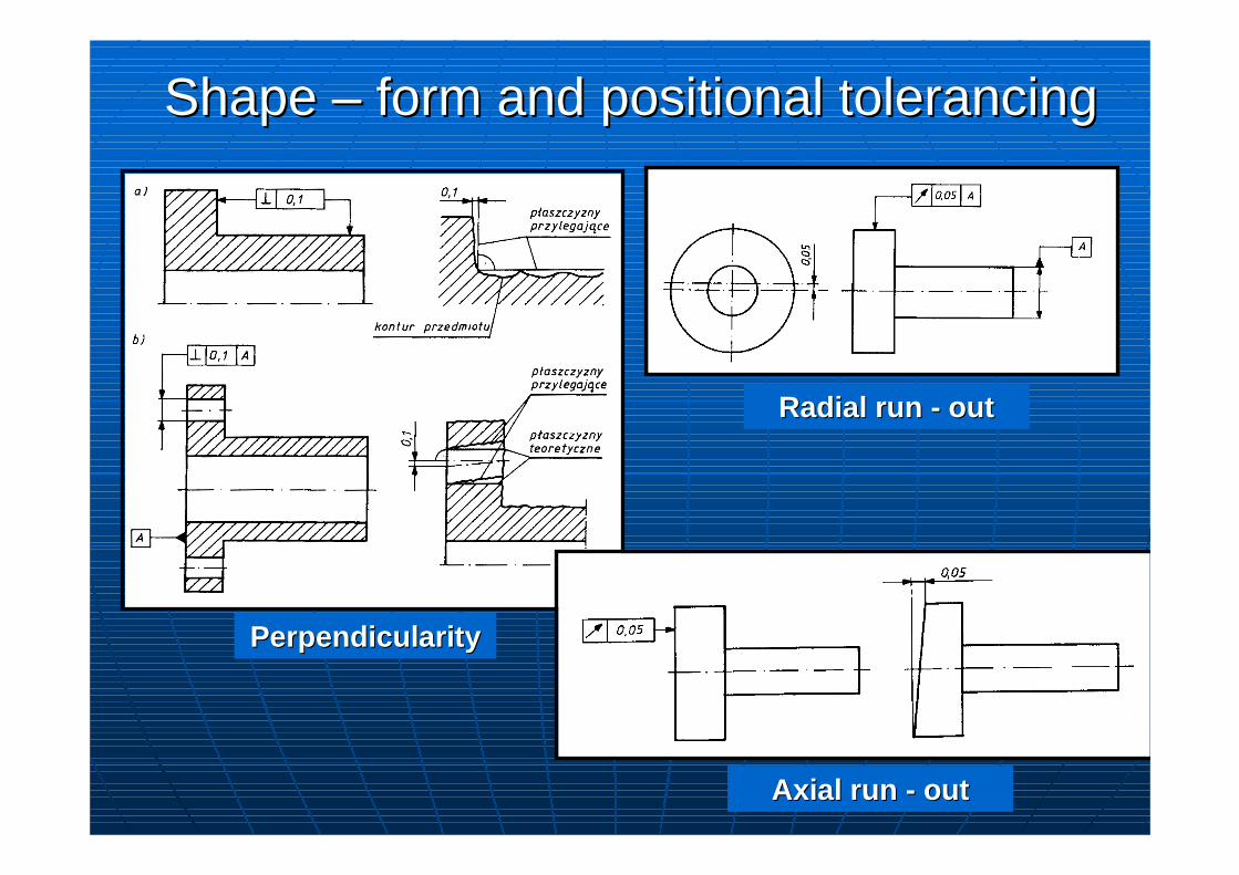
PerpendicularityPerpendicularity
Radial run Radial run -- outout
Shape Shape –– form and positional tolerancingform and positional tolerancing
Axial run Axial run -- outout