Embed Size (px)
Citation preview

Network Analyzer Basics www.agilent.com/find/backtobasics
1
Network Analyzer Basics

Network Analyzer Basics www.agilent.com/find/backtobasics
2
Network Analyzer Basics
Presented by:Jeff Murphy – Agilent TechnologiesRF/MW Application EngineerAtlanta, GA(678)566-6052 [email protected]
Agenda
•VNA Overview and Transmission Line Review•Network Analyzer Hardware and S-parameter Review•Error Modeling and Calibration •Cable/PCI Express Example Measurements•Balanced VNA Solutions•Connector handling•4-port ENA Vector Network Analyzer Demo (8.5 Ghz)

Network Analyzer Basics www.agilent.com/find/backtobasics
3
Example Network Analyzer Measurements - BPF CH1 S11 log MAG 5 dB/ REF 0 dB
CENTER 200.000 MHz SPAN 50.000 MHz
Return loss
log MAG 10 dB/ REF 0 dBCH1 S
21
START .300 000 MHz STOP 400.000 000 MHz
Cor
69.1 dB
Stopband
rejection
Insertion loss
SCH1 21 log MAG 1 dB/ REF 0 dB
Cor
Cor
START 2 000.000 MHz STOP 6 000.000 MHz
x2 1 2
m1: 4.000 000 GHz -0.16 dBm2-ref: 2.145 234 GHz 0.00 dB
1
ref 2

Network Analyzer Basics www.agilent.com/find/backtobasics
4
The Need for Both Magnitude and Phase
4. Time-domain characterization
Mag
Time
5. Vector-error correction
Error
MeasuredActual
2. Complex impedance needed to design matching circuits
3. Complex values
needed for device modeling
1. Complete characterization of linear networks
High-frequency transistor model
Collector
Base
Emitter
S21
S12
S11 S22

Network Analyzer Basics www.agilent.com/find/backtobasics
5
Transmission Line Terminated with Zo
For reflection, a transmission line terminated in Zo behaves like an infinitely long transmission line
Zs = Zo
Zo
Vrefl = 0! (all the incident power is absorbed in the load)
Vinc
Zo = characteristic impedance of transmission line

Network Analyzer Basics www.agilent.com/find/backtobasics
6
Transmission Line Terminated with Short, Open
Zs = Zo
Vrefl
Vinc
For reflection, a transmission line terminated in a short or open reflects all power back to source
In-phase (0o) for open, out-of-phase (180o) for short

Network Analyzer Basics www.agilent.com/find/backtobasics
7
High-Frequency Device Characterization
TransmittedIncident
TRANSMISSION
Gain / Loss
S-ParametersS21, S12
GroupDelay
TransmissionCoefficient
Insertion
Phase
ReflectedIncident
REFLECTION
SWR
S-ParametersS11, S22
ReflectionCoefficient
Impedance, Admittance R+jX
, G+jB
Return
Loss
Incident
Reflected
TransmittedRB
A
A
R=
B
R=

Network Analyzer Basics www.agilent.com/find/backtobasics
8
Reflection Parameters
dB
No reflection(ZL = Zo)
RL
VSWR
0 1
Full reflection(ZL = open,
short)
0 dB
1
=ZL ZO
ZL + OZ
Reflection Coefficient =
Vreflected
Vincident
= = Return loss = -20 log(),
Voltage Standing Wave Ratio
VSWR = Emax
Emin=
1 + 1 -
Emax
Emin

Network Analyzer Basics www.agilent.com/find/backtobasics
9
Network Analyzer BasicsAgenda
•VNA Overview and Transmission Line Review•Network Analyzer Hardware and S-parameter Review•Error Modeling and Calibration •Cable/PCI Express Example Measurements•Balanced VNA Solutions•Connector handling•4-port ENA Vector Network Analyzer Demo (8.5 Ghz)

Network Analyzer Basics www.agilent.com/find/backtobasics
10
Switch
Source
R1
A
Port 1
R2
B
Port 2
Measurement
Receivers
Reference Receiver
Reference Receiver
General Network Analyzer Block Diagram

Network Analyzer Basics www.agilent.com/find/backtobasics
11
Smith Chart Review
Smith Chart maps
rectilinear impedanceplane onto polar plane
0+R
+jX
-jX
Rectilinear impedance plane
.
-90 o
0o180 o+-
.2
.4
.6
.8
1.0
90
o
Polar plane
Z = ZoL
= 0
Constant X
Constant R
Smith chart
LZ = 0
=±180 O1
(short) Z = L
= 0 O
1
(open)

Network Analyzer Basics www.agilent.com/find/backtobasics
12
Why Use S-Parameters?
relatively easy to obtain at high frequencies measure voltage traveling waves with a vector network
analyzer don't need shorts/opens which can cause active devices to
oscillate or self-destruct relate to familiar measurements (gain, loss, reflection
coefficient ...) can cascade S-parameters of multiple devices to predict
system performance can compute H, Y, or Z parameters from S-parameters if
desired can easily import and use S-parameter files in our electronic-simulation tools
Incident
TransmittedS21
S11Reflected S22Reflecte
dTransmitted
Incident
b1
a1b2
a2S12
DUT
b1= S11a1+S12a2
b2=S21a1 +S22a2
Port 1 Port 2

Network Analyzer Basics www.agilent.com/find/backtobasics
13
Measuring S-Parameters
S 11 = Reflected
Incident=
b1
a 1 a2 =0
S 21 =Transmitted
Incident=
b2
a 1 a2 =0
S 22 = Reflected
Incident=
b2
a 2 a1 =0
S 12 =Transmitted
Incident=
b1
a 2 a1 =0
Incident
TransmittedS
21
S11
Reflectedb1
a1
b2
Z0
Loada2 =0
DUTForward
Incident
Transmitted S
12
S22
Reflected
b2
a2b
a1=0
DUTZ0
Load Reverse
1

Network Analyzer Basics www.agilent.com/find/backtobasics
14
Agilent’s Series of RF Vector Analyzers
8753ET/ES series
3, 6 GHz – 50/75
rich feature set
PNA series (Highest Performance)
3, 6, 9 GHz - 2, 3 ports highest dynamic range internal Windows automation (open
Windows system) program via SCPI or COM/DCOM 50/75
8712ET/ES series
1.3, 3 GHz - 50/75
low cost narrowband
and broadband detection
IBASIC / LAN
ENA series (Mid Performance)
3, 8.5 GHz – 50 2, 3, 4 ports 7, 9 ports with test
set excellent RF
performance balanced
measurements internal VBA
automation
ENA-L series (Lowest Cost)
1.5, 3 GHz – 2 ports Low cost internal VBA
automation 50/75
Planned discontinuance June 2004

Network Analyzer Basics www.agilent.com/find/backtobasics
15
Agilent’s Series of Microwave Vector Analyzers
8510C series
110 GHz in coax
modular, flexible
pulse systems
Tx/Rx module testPNA/PNA-L series
20, 40, 50 GHz PNA & PNA-L 67 GHz PNA 110+ GHz w/ external test set
(PNA) highest dynamic range and
speed very low trace noise advanced LAN connectivity internal Windows automation program via SCPI or
COM/DCOM
8720ET/ES series 13.5, 20, 40 GHz economical fast, small,
integrated test mixers, high-
power ampsDiscontinued

Network Analyzer Basics www.agilent.com/find/backtobasics
16
Network Analyzer BasicsAgenda
•VNA Overview and Transmission Line Review•Network Analyzer Hardware and S-parameter Review•Error Modeling and Calibration •Cable/PCI Express Example Measurements•Balanced VNA Solutions•Connector handling•4-port ENA Vector Network Analyzer Demo (8.5 Ghz)

Network Analyzer Basics www.agilent.com/find/backtobasics
17
Systematic errors due to imperfections in the analyzer and test
setup assumed to be time invariant (predictable)
Random errors vary with time in random fashion (unpredictable) main contributors: instrument noise, switch and
connector repeatabilityDrift errors
due to system performance changing after a calibration has been done
primarily caused by temperature variation
Measurement Error Modeling
Measured Data
Unknown Device
SYSTEMATIC
RANDOM
DRIFT
Errors:
CAL
RE-CAL

Network Analyzer Basics www.agilent.com/find/backtobasics
18
Systematic Measurement Errors
A B
SourceMismatch
LoadMismatch
Crosstalk
Directivity
DUT
Frequency response reflection tracking (A/R) transmission tracking
(B/R)
R
Six forward and six reverse error terms yields 12 error terms for two-port devices

Network Analyzer Basics www.agilent.com/find/backtobasics
19
What is Vector-Error Correction?
Process of characterizing systematic error terms
measure known standards remove effects from subsequent measurements
1-port calibration (reflection measurements) only 3 systematic error terms measured directivity, source match, and reflection
tracking Full 2-port calibration (reflection and
transmission measurements) 12 systematic error terms measured usually requires 12 measurements on four
known standards (SOLT) Standards defined in cal kit definition file
network analyzer contains standard cal kit definitions
CAL KIT DEFINITION MUST MATCH ACTUAL CAL KIT USED!
User-built standards must be characterized and entered into user cal-kit

Network Analyzer Basics www.agilent.com/find/backtobasics
20
Errors and Calibration Standards
Convenient Generally not
accurate No errors
removed Easy to perform Use when
highest accuracy is not required
Removes frequency response error
For reflection measurements
Need good termination for high accuracy with two-port devices
Removes these errors: Directivity Source match Reflection tracking
Highest accuracy Removes these
errors: Directivity Source, load match Reflection tracking Transmission tracking Crosstalk
UNCORRECTED RESPONSE 1-PORT FULL 2-PORT
DUT
DUT
DUT
DUT
thru
thru
ENHANCED-RESPONSE Combines response and 1-port Corrects source match for
transmission measurements
SHORT
OPEN
LOAD
SHORT
OPEN
LOAD
SHORT
OPEN
LOAD

Network Analyzer Basics www.agilent.com/find/backtobasics
21
Return Loss (Match) Before and After One-Port Calibration
Return Loss before 1-port calibration
data after 1-port calibration
0
20
40
60
6000 12000
2.0
Retu
rn L
oss (
dB
)
VS
WR
1.1
1.01
1.001
MHz

Network Analyzer Basics www.agilent.com/find/backtobasics
22
Response versus Two-Port Calibration
CH1 S21&M log MAG 1 dB/ REF 0 dB
Cor
CH2 MEM log MAG REF 0 dB1 dB/
Cor
Uncorrected
After two-port calibration
START 2 000.000 MHzSTOP 6 000.000 MHz
x2 1 2
After response calibration
Measuring filter insertion loss

Network Analyzer Basics www.agilent.com/find/backtobasics
23
• Variety of modules cover 300 kHz to 67 GHz
• 4-port versions available for < 9 GHz
• Choose from six connector types (50 and 75 )
• Mix and match connectors (3.5mm, Type-N, 7/16)
• Single-connection reduces calibration time makes calibrations easy to
perform minimizes wear on cables and
standards eliminates operator errors
• Highly repeatable temperature-compensated terminations provide excellent accuracy
ECal: Electronic Calibration (85060/90 series)
85093A Electronic Calibration Module30 kHz - 6 GHz
Microwave modules use a transmission line shunted by PIN-diode switches in
various combinations

Network Analyzer Basics www.agilent.com/find/backtobasics
24
Calibrating Non-Insertable Devices
When doing a through cal, normally test ports mate directly
cables can be connected directly without an adapter
result is a zero-length through What is an insertable device?
has same type of connector, but different sex on each port
has same type of sexless connector on each port (e.g. APC-7)
What is a non-insertable device? one that cannot be inserted in place of a
zero-length through has same connectors on each port (type
and sex) has different type of connector on each
port (e.g., waveguide on one port, coaxial on the other)
What calibration choices do I have for non-insertable devices?
use an uncharacterized through adapter use a characterized through adapter
(modify cal-kit definition) swap equal adapters adapter removal
DUT

Network Analyzer Basics www.agilent.com/find/backtobasics
25
Thru-Reflect-Line (TRL) Calibration
We know about Short Open Load Thru (SOLT) calibration...What is TRL?
A two port calibration technique Good for noncoaxial environments (waveguide,
fixtures, wafer probing) Uses the same 12 term error model as the
more common SOLT cal Uses practical calibration standards that
are easily fabricated and characterized
Two variations: TRL (requires 4 receivers) and TRL* (only three receivers needed)
Other variations: Line Reflect Match (LRM), Thru Reflect Match (TRM),
plus many others
TRL was developed for non-coaxial microwave
measurements

Network Analyzer Basics www.agilent.com/find/backtobasics
26
start with broadband frequency sweep (often requires microwave VNA)
use inverse-Fourier transform to compute time-domain resolution inversely proportionate to frequency span
CH1 S22 Re 50 mU/ REF 0 U
CH1 START 0 s STOP 1.5 ns
Cor
20 GHz
6 GHz
Time Domain Frequency Domain
t
f
1/s*F(s)
F(t)*dt0
t
Integrate
ft
f
TDRF -
1
TDR Basics Using a Network Analyzer
F -1

Network Analyzer Basics www.agilent.com/find/backtobasics
27
Time-Domain Gating TDR and gating can remove undesired reflections (a
form of error correction) Only useful for broadband devices (a load or thru for
example) Define gate to only include DUT Use two port calibration
CH1 MEM Re 20 mU/ REF 0 U
CH1 START 0 s STOP 1.5 ns
CorPRm
RISE TIME 29.994 ps 8.992 mm
1
2
3
1: 48.729 mU 638 ps
2: 24.961 mU 668 ps 3: -10.891
mU 721 ps
Thru in time domain
CH1 S11
&M log MAG 5 dB/ REF 0 dB
START .050 000 000 GHz STOP 20.050 000 000 GHz
Gate
Cor
PRm
1
2
2: -15.78 dB 6.000 GHz
1: -45.113 dB 0.947 GHz
Thru in frequency domain, with and without gating

Network Analyzer Basics www.agilent.com/find/backtobasics
28
Network Analyzer BasicsAgenda
•VNA Overview and Transmission Line Review•Network Analyzer Hardware and S-parameter Review•Error Modeling and Calibration •Cable/PCI Express Example Measurements•Balanced VNA Solutions•Connector handling•4-port ENA Vector Network Analyzer Demo (8.5 Ghz)

Network Analyzer Basics www.agilent.com/find/backtobasics
29
What are Balanced Devices?Ideally, respond to differential and reject common-mode signals
Differential-mode signal
Common-mode signal
(EMI or ground noise)
Gain = 1
Differential-mode signal
Common-mode signal
(EMI or ground noise)
Gain = 1
Balanced to single-ended
Fully balanced

Network Analyzer Basics www.agilent.com/find/backtobasics
30
Balanced Components in Real World
• Mode conversions occur...
+
Differential to common-mode
conversion
Common-mode to differential conversion
Generates EMI
Susceptible to EMI

Network Analyzer Basics www.agilent.com/find/backtobasics
31
Complete Characterization Complete frequency domain views
Port 1
Single-endedBalanced port 1
Balanced
44434241
34333231
24232221
14131211
SSSS
SSSS
SSSS
SSSS
Stimulus
Resp
on
se
22CC21CC22CD21CD
12CC11CC12CD11CD
22DC21DC22DD21DD
12DC11DC12DD11DD
SSSS
SSSS
SSSS
SSSS
Common InDifferential Out
Differential In Differential Out
mode conversion terms
Differential InCommon Out
mode conversion
terms
Common In Common Out
Balanced port 2 Port 3
Port 2 Port 4

Network Analyzer Basics www.agilent.com/find/backtobasics
32
Attenuation, Return Loss, LCL- LAN cable
Sdd21, Ins Loss
Sdc11, LCL
Sdd11, Zin
Sdd11, Ret Loss
Test FixturePN 04380-60101
Pair to be tested

Network Analyzer Basics www.agilent.com/find/backtobasics
33
. . .
NEXT-1
NEXT- 4
DUT
Crosstalk Measurement
ex) Near-end Crosstalk (NEXT)
Power sum NEXT = NEXT-1 + NEXT-2 + NEXT-3 + NEXT-4
ACR NEXT = Attenuation – Power sum NEXT

Network Analyzer Basics www.agilent.com/find/backtobasics
34
50 ohms
50 ohms
45 ohms55 ohms
Unbalanced termination impedance causescrosstalk measurement errors
DUT
Terminations for Accurate Crosstalk Measurement

Network Analyzer Basics www.agilent.com/find/backtobasics
35
Power Sum NEXT Measurement- PCI Express Connector
VBA calculates Power Sum NEXT andplot it on the ENA’s screen.
Ret.Loss
Ins.Loss

Network Analyzer Basics www.agilent.com/find/backtobasics
36
Characteristic Impedance Zc Measurement- LAN CableCharacteristic Impedance Zc
(Calculated from Sdd11,Sdd21,Sdd12 and Sdd22 using built-in VBA.)

Network Analyzer Basics www.agilent.com/find/backtobasics
37
Current Issue
• How do you eliminate the influence of test fixtures from measurement results?
• Using the customized test fixture with calibration kit is one of solutions but these are very expensive and inflexible

Network Analyzer Basics www.agilent.com/find/backtobasics
38
Concept of In-Fixture Characterization
Exclude two-port network from measured S-parameter• De-embedding networks can be applied to individual ports• Undesired network is specified by Touchstone file (.s2p)
Remove unwanted test fixture effect
Network #1
Network #2
Network #3

www.agilent.com/find/backtobasics
39Network Analyzer Basics
Concept of In-Fixture Characterization• The ENA calculates S-parameters of each network
based on three measurement (OSL) results using the adapter characterization program
S11M
Edf: Forward Directivity ErrorEsf: Forward Source MatchErf: Forward Reflection Tracking
Erf
1
Edf Esf
StandardsOpen/Short/Load
Network #1

Network Analyzer Basics www.agilent.com/find/backtobasics
40
Agilent ENA Series RF NetworkAnalyzer, E5070A/71A• The ENA Series with Cascade’s probing System provides highly accurate in-fixture characterization method with easy operation
Cascade Microtech• Summit 9000 RF Probe Station• Air Coplanar Probe (ACP)• Impedance Standard Substrate (ISS)
Probing System Configuration

Network Analyzer Basics www.agilent.com/find/backtobasics
41
Measurement Example Each test port is characterized by using ENA with Cascade’s probe
• Adapter characterization program calculates S-parameter using the measured S11 data (O, S, L), and S11 definitions of standards (O, S, L)• ENA can export .s2p data for the fixture de-embedding Open
Std.Short Std.Load Std.

Network Analyzer Basics www.agilent.com/find/backtobasics
42
Network Analyzer BasicsAgenda
•VNA Overview and Transmission Line Review•Network Analyzer Hardware and S-parameter Review•Error Modeling and Calibration •Cable/PCI Express Example Measurements•Balanced VNA Solutions•Connector handling•4-port ENA Vector Network Analyzer Demo (8.5 Ghz)

Network Analyzer Basics www.agilent.com/find/backtobasics
43
Agilent Solutions for Balanced Measurements• For RF wireless and general-purpose devices:
• ENA series is recommended choice (3, 8.5 GHz)• measure standard or mixed-mode S-parameters• fixture simulator to embed/de-embed
and transform test port impedances• 4-port ECal for fast and easy calibration
• For microwave or signal-integrity applications up to 50GHz (rise time 14.4ps)• N1948A,N1953/55/57B systems• consist of network analyzer,
test set, external software• time domain, eye diagrams,
RLCG extraction• ECal available up to 9 GHz
Network Analyzer Basics www.agilent.com/find/backtobasics
44
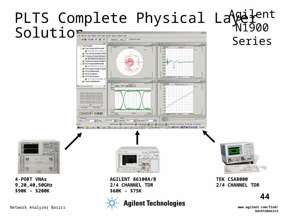
PLTS Complete Physical Layer Solution
4-PORT VNAs9,20,40,50GHz$90K - $200K
AGILENT 86100A/B2/4 CHANNEL TDR$60K - $75K
TEK CSA80002/4 CHANNEL TDR
Agilent N1900 Series

Network Analyzer Basics www.agilent.com/find/backtobasics
45
Complete Characterization Fast and accurate eye diagrams
Simulated Bit Pattern(Arbitrary Bitstream (ABS)
or User-defined)
Simulated Bit Pattern(Arbitrary Bitstream (ABS)
or User-defined)
EyeDiagram
EyeDiagram
Measured Data (TDR or
VNA)
Measured Data (TDR or
VNA)
Impulse Response
Impulse Response
ConvolutionConvolution

Network Analyzer Basics www.agilent.com/find/backtobasics
46
TDR-based or VNA-based PLTS System?There is no fundamental difference in the information content
between the time domain and the frequency domain (there is a difference in the capabilities of the two systems) – Eric Bogatin, GigaTest Labs Customer Concerns Ideal System
TDR-based
VNA-based Both
Greatest Ease of Use, Quick Set Up X Good First-Order Models X Calculates Excess Reactance X Best Dynamic Range (SNR) for very low loss components, low levels of mode conversion, crosstalk, etc.
X
Best Higher-Order Models X Characterize Small Coupling Effects X Highest Accuracy X Fixture De-Embedding Capability X S-Parameters X

Network Analyzer Basics www.agilent.com/find/backtobasics
47
Network Analyzer BasicsAgenda
•VNA Overview and Transmission Line Review•Network Analyzer Hardware and S-parameter Review•Error Modeling and Calibration •Cable/PCI Express Example Measurements•Balanced VNA Solutions•Connector handling•4-port ENA Vector Network Analyzer Demo (8.5 Ghz)

Network Analyzer Basics www.agilent.com/find/backtobasics
48
Connector Considerations
A significant factor in repeatability and accuracy Selecting the best of several types for application
(grade) Compatibility Connectors are consumables
– limited lifetime– damaged connectors are costly– proper care maximizes lifetime

Network Analyzer Basics www.agilent.com/find/backtobasics
49
Slotted Female Centre Conductor

Network Analyzer Basics www.agilent.com/find/backtobasics
50
Connector Examples
Type F
BNC
SMC
Type N
APC 7
SMA
3.5 mm
2.92 mm or K
2.4 mm
MaleFemale FemaleMale

Network Analyzer Basics www.agilent.com/find/backtobasics
51
Cost of Connector Damage

Network Analyzer Basics www.agilent.com/find/backtobasics
52
To Learn More… To Learn More…
Signal Integrity Web Resource: www.agilent.com/find/si
PLTS Home Page: www.agilent.com/find/plts
Email Update Service: www.agilent.com/emailnotification
T&M Web Resource: www.agilent.com/find/products
Application Notes for VNAs www.agilent.com/find/na_appnotes
Support, Service, and Assistance from Agilent Contact Centers Worldwide:
United States: (800)829-4444
Channel Partners (partial list):
GigaTest Labs (Probing products, services, training ): www.gigatest.com
Cascade Microtech (High-speed probes ): www.cmicro.com
TDA Systems (IConnect, MeasureXtractor): www.tdasystems.com

Network Analyzer Basics www.agilent.com/find/backtobasics
53
To Learn More… To Learn More…
PNA Series Network Analyzers: www.agilent.com/find/pna
ENA Series Network Analyzers: www.agilent.com/find/ena
Electronic Calibration: www.agilent.com/find/ecal
Back To Basics Online Training: www.agilent.com/find/backtobasicsDifferential S-Parameter Measurements of PCI Express Connector Using the ENA Series Network
Analyzer (AN1463-3) 5988-9848EN
In-Fixture Characterization Using the ENA Series RF Network Analyzer with Cascade Microtech Probing System 5988-6522EN
An Introduction to Multiport and Balanced Device Measurements (AN 1373-1) 5988-5634EN
VNA-Based System Tests the Physical Layer - Application Note 1382-7 5988-5075EN
10 Hints for Making Better Network Analyzer Measurements - Application Note 1291-1B5965-8166E
Agilent 8510-13 Measuring Noninsertable Devices – Product Note 5956-4373E
Agilent AN 154 S-Parameter Design - 5952-1087
S-parameter Techniques – Application Note 95-1
Agilent AN 1287-3 Applying Error Correction to Network Analyzer Measurements5965-7709E
De-embedding and Embedding S-Parameter Networks Using a Vector Network Analyzer – AN 1364-15980-2784EN
Understanding the Fundamental Principles of Vector Network Analysis Application Note 1287-15965-7707E
Agilent AN 1287-9 In-Fixture Measurements Using Vector Network Analyzers 5968-5329E
Exploring the Architectures of Network Analyzers Application Note 1287-2 5965-7708E
Intro to the Fixture Simulator Function of the ENA Series RF NA: Network De-embedding/Embedding and Balanced Meas 5988-4923EN

Network Analyzer Basics www.agilent.com/find/backtobasics
54
Network Analyzer BasicsAgenda
•VNA Overview and Transmission Line Review•Network Analyzer Hardware and S-parameter Review•Error Modeling and Calibration •Cable/PCI Express Example Measurements•Balanced VNA Solutions•Connector handling•4-port ENA Vector Network Analyzer Demo (8.5 Ghz)