Embed Size (px)
Citation preview
WSDOT PAVEMENT POLICY
JUNE 2015
Washington State Department of Transportation
Construction Division Pavements Office P.O. Box 47365 Olympia, WA 98504-7365

TABLE OF CONTENTS
1. INTRODUCTION 1
1.1 Purpose 1
1.2 Relationship to WSDOT Design Manual 1
1.3 Scope and Applicability 1
2. BASIS OF WSDOT DESIGN POLICY 3
2.1 Background 3
2.2 Concrete Pavement 3
2.3 HMA Pavement 5
2.4 Surface Treatment Pavements 6
2.5 Re-use of Existing Pavement Structures 6
2.6 Pavement Preservation 7
3. PAVEMENT DESIGN CONSIDERATIONS 9
3.1 Design Period 9
3.2 Traffic 9
3.3 Subgrade Soils 10
3.4 Frost Action 10
3.5 Design Resources 10
4. PAVEMENT TYPE SELECTION 13
4.1 Application of Pavement Type Selection 13
4.2 Submittal Process 15
5. NEW PAVEMENT DESIGN 17
5.1 Design Procedures 17
5.2 Determination of Flexible Pavement Layer Thicknesses 17
5.3 Determination of Rigid Pavement Layer Thicknesses 22
5.4 Permeable Pavements 24
6. PAVEMENT REHABILITATION 27
6.1 Cold In-Place Recycling 28
6.2 Full Depth Reclamation 29
6.3 Crack, Seat and Overlay 30
6.4 Unbonded Concrete Overlay 30
6.5 HMA Structural Overlay 31

7. PAVEMENT PRESERVATION 33
7.1 Chip Seals 33
7.2 Hot Mix Asphalt 36
7.3 Portland Cement Concrete Pavements 41
7.4 Other Pavement Preservation Treatments 43
8. PREVENTIVE PRESERVATION 47
9. DESIGN DETAILS 49
9.1 General Design Details 49
9.2 HMA Design Details 50
9.3 Cement Concrete Pavement Design Details 52
10. PAVEMENT DESIGN REPORT 55
10.1 Project Description 55
10.2 Site Evaluation 56
10.3 Pavement Design 57
10.4 Design Details 57
10.5 HQ Pavements office Pavement Design Report Approval 58
APPENDIX 1 – DOWEL BAR TYPE SELECTION 61
APPENDIX 2 – FROST DEPTH CONTOUR MAPS 65
APPENDIX 3 – PAVEMENT TYPE SELECTION CRITERIA 69
APPENDIX 4 – EXAMPLE PAVEMENT TYPE SELECTION REPORT 83
APPENDIX 5 – WSDOT PROBABILISTIC INPUTS 111
APPENDIX 6 – PROBABILISTIC ANALYSIS EXAMPLE 115
APPENDIX 7 – PROJECT SPECIFIC DETAILS 127
APPENDIX 8 – WSDOT PAVEMENT TYPE SELECTION COMMITTEE AND SAMPLE MEMORANDUM 129
WSDOT Pavement Policy
June 2015 1
1. INTRODUCTION
1.1 PURPOSE
The purpose of this document is to establish a uniform policy for the selection of pavement
types, design of pavement structures and selecting pavement materials for use by pavement
designers throughout the state. It is not intended as a replacement for engineering judgment.
Nor is it a comprehensive manual on pavement design and designers using this document
should have a basic understanding of pavement design, pavement construction and paving
materials.
1.2 RELATIONSHIP TO WSDOT DESIGN MANUAL
Pavement design information previously contained in the Design Manual is largely replaced by
this document. Refer to Division 6 of the Design Manual for any additional pavement related
information.
1.3 SCOPE AND APPLICABILITY
This manual is intended for design of highway pavement and other facilities that are part of
Washington’s highway system. Facilities owned by WSDOT but not part of the highway system
are not required to comply with this document. Pavement and facilities maintained by local
agencies should be designed to the standards of the local agency.
This manual contains standards for selecting pavement types, designing pavement structure
and selecting pavement materials. Specific requirements for pavement materials are covered in
other WSDOT manuals including the Standard Specifications and the Materials Manual.
This document is maintained by the Engineering and Regional Operations Construction Division
Pavements Office (HQ Pavements). The HQ Pavements Office should be contacted with any
questions regarding this manual.

WSDOT Pavement Policy
June 2015 2
WSDOT Pavement Policy
June 2015 3
2. BASIS OF WSDOT DESIGN POLICY
2.1 BACKGROUND
WSDOT’s pavement design policy is a product of experience, research findings (state, national
and international) and various analyses. The policy is based upon pavement design practices
that WSDOT has found to produce serviceable and cost effective pavements for the conditions
in Washington State. Generally these practices follow conventional pavement design
procedures. Practices that have shaped WSDOT’s pavement design policy include:
• Designing pavement structures for long-life (50 years or more),
• Designing HMA pavement to ensure that cracking occurs from the top down instead of
from the bottom up,
• Reusing the existing pavement structure as much as practical when rehabilitating an
existing pavement, and
• Incorporating pavement preservation at both the capital project level as well as the state
forces maintenance level.
These practices are the basis of many of the requirements in this pavement design policy.
Background information describing how these practices came about is provided in following
sections.
2.2 CONCRETE PAVEMENT
The policy of designing long-life concrete pavements grew out of the historical performance of
concrete pavements in Washington. Paving concrete used in Washington has historically
performed well structurally and has not suffered from any significant durability problems. The
limiting failure mechanisms have therefore been those that do not involve the concrete material
itself such as faulting, roughness and studded tire wear. If the non-concrete material related
failure mechanisms are designed to perform over a long design life, a long-life pavement could
be achieved. The following describes the strategies used by WSDOT for each concrete
pavement design element to design long life concrete pavement.

WSDOT Pavement Policy
June 2015 4
2.2.1 THICKNESS
WSDOT designed the concrete pavements constructed during the 1960’s and 1970’s as part of
the original interstate construction with an 8 or 9 inch thickness. Originally designed for a 20-
year life, many are still in service, far exceeding their design lives. With a moderate increase in
thickness to account for increased ESALs, the structural performance of the earlier pavements
show that concrete pavements in Washington could be constructed to resist structural failure for
50 years or more.
Washington allows studded tires from November through March. Rutting (wear) in the wheel
paths due to studded tires has been deep enough to require correction on some concrete
pavement sections. Wear due to studded tires will continue to be a problem. WSDOT designs
new concrete pavements with an extra inch of thickness to account for diamond grinding to
remove ruts caused by studded tire wear.
2.2.2 DURABILITY
Concrete pavements in Washington have not suffered from significant durability problems that
can limit pavement life in other parts of the country. The durability of concrete pavements
primarily arises from the availability of high quality aggregates. Supplies of high quality
aggregates appear to be available for the foreseeable future allowing the production of concrete
that can provide a long pavement life.
2.2.3 JOINTING AND LOAD TRANSFER
A major failure mechanism that affected the performance of WSDOT’s original concrete
pavement sections was load transfer at transverse joints. Originally constructed without dowel
bars, concrete pavements were susceptible to faulting. Many of these pavements required
rehabilitation in the form of dowel bar retrofits and grinding. To address faulting, new
pavements are doweled to improve joint load transfer.
Experience has shown that spacing transverse contraction joints at 15 feet did not result in
significant amounts of shrinkage cracking. The 15-foot spacing was retained as the standard
spacing for transverse contraction joints.
WSDOT Pavement Policy
June 2015 5
2.2.4 DOWEL BAR MATERIALS
A long pavement life necessitates that dowel bars be able to resist corrosion. Inspection of
epoxy coated dowel bars removed from in service pavements revealed that they are susceptible
to corrosion in Washington conditions. In order to achieve a long life WSDOT requires stainless
steel or equivalent dowels (see Appendix 1 for dowel bar materials) in all new concrete
pavement. Epoxy coated dowel bars are allowed in applications that do not have as long of a
life such as dowel bar retrofits and replacing damaged panels in an existing concrete pavement.
2.2.5 CONCRETE PAVEMENT BASE
In the past, base depths under rigid pavements were determined primarily by the requirement
for support of construction traffic. Currently, it is recognized that the layer directly beneath PCC
slabs is a critical element in the performance of PCC pavement. WSDOT has previously used
asphalt treated base (ATB) to support construction traffic prior to placement of PCC pavement.
Subsequent WSDOT experience has indicated variable performance for ATB material beneath
various Interstate PCC pavements. For this reason, HMA base is required as the supporting
layer for PCC slabs for high traffic roadways.
2.3 HMA PAVEMENT
WSDOT’s long-life HMA design policy is based on the concept of perpetual pavement and that
cracking in thicker HMA sections will primarily be top down. Cracks in HMA pavements, thicker
than approximately 6 inches, tend to start at the top of the pavement and propagate down
instead of starting at the bottom and propagating up. By correcting surface distress on a thicker
HMA pavement before it propagates into the lower layers, the underlying structure can be
preserved allowing the pavement to have a long life.
2.3.1 THICKNESS
Traditional HMA pavement design methods have focused on providing a structure that limits the
amount of bottom-up cracking over the pavements life. This method allows the use of a
relatively thin HMA saving cost during the initial construction. In these methods, cracking starts
at the bottom of the pavement and progress upwards through the entire pavement structure. At
the end of the pavements life, bottom-up cracking becomes widespread resulting in the
pavement losing its ability to carry loads. Restoring the load carrying capacity requires a costly
major rehabilitation or reconstruction which usually requires replacement or reprocessing of the
WSDOT Pavement Policy
June 2015 6
existing HMA pavement structure. WSDOT has found that cracking in thicker HMA pavement
actually occurs from the top down. If timely preservation is performed to correct the top-down
cracking, damage to the underlying layers can be prevented thus preserving the pavement
structure. It is WSDOT’s policy to use a long design life that results in a relatively thick HMA
pavement structure. The thick HMA pavement can then be preserved using thin mill and inlay
projects that remove the top-down cracks by milling off the top lift of HMA and inlaying with an
equal thickness of new HMA. The thicker pavement is more costly during the initial construct
but is offset by the savings realized by the lower cost to preserve the pavement.
2.3.2 HMA PRESERVATION
The goal of HMA preservation is to protect the underlying structure by replacing top layers
before distress that initiates at the top of the pavement damages the underlying structural
layers. WSDOT employs two complimentary strategies to preserve HMA pavement. The first is
the thin mill and inlay mentioned above. The goal of the mill and inlay is to remove the top layer
of HMA which removes most of the top-down cracks and the aged, crack-susceptible top layer
of HMA and replaces it with new HMA. The second strategy is to use preservation treatments
such as crack sealing, surface treatments and patching to extend the time between the thin mill
and inlay projects.
2.4 SURFACE TREATMENT PAVEMENTS
Chip seals are a primary surface treatment used by WSDOT due to their simplicity, low cost and
the ability to withstand studded tire wear. Although they are not often thought of as long-life
pavement structures, the underlying pavement structure on a chip seal roadway can have a
long life. This requires that the additional chip seals be periodically applied to prevent water
intrusion and damage to the underlying structure. Despite the frequent reapplication of the chip
seal surface, these types of roadway can have a much lower life cycle cost than concrete or
HMA roadways provided the location and traffic levels are appropriate.
2.5 RE-USE OF EXISTING PAVEMENT STRUCTURES
For existing pavement structures which require significant structural enhancements, long-lasting
pavements can be achieved by incorporation of the existing pavement. Structural design
WSDOT Pavement Policy
June 2015 7
incorporating existing pavements is similar to all new pavement designs but considerations
associated with the existing pavement are required. A reliable procedure is available that
identifies when existing pavements can be used in-place and the methods necessary to
incorporate the original material into the new pavement structure while achieving long life.
Recent national research aided by information and support from the WSDOT has provided
additional understanding and design aids for achieving long-lasting designs which incorporate
the existing (or modified) pavement structure. The national research produced rePave which is
used by WSDOT for selecting rehabilitation strategies.
2.6 PAVEMENT PRESERVATION
WSDOT uses principles associated with pavement preservation to manage the state highway
system. The preservation cycle begins immediately after construction since the effects of traffic,
climate, and traction devices will deteriorate pavement structures. Preservation starts with how
a new or reconstructed pavement structure is designed and constructed and continues through
the complete life-cycle.

WSDOT Pavement Policy
June 2015 8
WSDOT Pavement Policy
June 2015 9
3. PAVEMENT DESIGN CONSIDERATIONS
3.1 DESIGN PERIOD
The design period is the time from original construction to a terminal condition for a pavement
structure. AASHTO essentially defines design period, design life and performance period as
being the same terms. AASHTO defines an analysis period as the time for which an economic
analysis is to be conducted. Further, the analysis period can include provisions for periodic
surface renewal or rehabilitation strategies which will extend the overall service life of a
pavement structure before complete reconstruction is required.
The design period used by WSDOT is chosen so that the design period traffic will result in a
pavement structure sufficient to survive through the analysis period. It is recognized that
intermittent treatments will be needed to preserve the surface quality and ensure that the
structure lasts through the analysis period. The required design period for all WSDOT highways
is 50 years.
The 50 year design period can be reduced for unique, project specific conditions such as
temporary pavement sections, HOV lanes, future realignment or grade changes.
Doubling the design period equivalent singe axle loads (ESALs) adds about 0.5 to 1.0 inches of
HMA or PCC to the required initial structural thickness of a flexible or rigid pavement design. As
such, modest increases in pavement thickness can accommodate significantly increased traffic
as characterized by ESALs.
3.2 TRAFFIC
The volume and character of traffic, expressed in terms of 18,000 lb. equivalent single axle
loads (ESALs), is a measure of the traffic loading experienced by a pavement. The ESAL
loading on a highway strongly influences pavement structural design requirements. Both
flexible and rigid pavement structures can be designed to meet any ESAL requirement;
however, this does not imply similar maintenance and rehabilitation requirements.
WSDOT Pavement Policy
June 2015 10
3.3 SUBGRADE SOILS
The characteristics of native soils directly affect the pavement structure design. A careful
evaluation of soil characteristics is a basic requirement for each individual pavement structure
design. Subgrade resilient modulus is the primary material input into the AASHTO Guide for
Design of Pavement Structures (1993).
3.4 FROST ACTION
Greater depths of base or selected free-draining borrow materials are necessary in areas where
frost action is severe or the subgrade soil is extremely weak. The total depth of the pavement
structure is extremely important in high frost penetration areas. Additional thickness of non-frost
susceptible base or subbase materials has been effectively used to combat this problem. An
effective measure is to have the pavement structure (total of surface and base courses) equal to
at least one-half the maximum expected depth of freeze when the subgrade is classified as a
frost susceptible soil. The depth of freeze is based on the design freezing index (30 year
temperature record) or measurements made by WSDOT during the severe winter of 1949-1950
(Appendix 2). The winter of 1949-1950 produced the greatest depth of freeze during the past
65 years.
3.5 DESIGN RESOURCES
WSDOT uses a range of tools and information to help assess, scope, and design pavement
structures. Some of the design resources include the following:
• Washington State Pavement Management System (WSPMS)
• Pavement Interactive (PI): A resource with basic pavement-oriented content along with
links to numerous pavement application programs. The PI was originally developed with
the support of the several state DOTs and the FHWA.
• Everseries software (PC based pavement analysis tools which include Everstress
(general layered elastic analysis tool), Evercalc (backcalculate pavement layer moduli
from FWD deflection basins), and Everpave (HMA overlay design for flexible
pavements).
WSDOT Pavement Policy
June 2015 11
• AASHTO Guide for Design of Pavement Structures (1993): This guide is used to design
flexible and rigid pavements.
• PaveXpress: A web based online tool for designing new and reconstructed flexible and
rigid pavements by the AASHTO 1993/1998 processes.
• rePave: A web based online process to scope long-lasting pavements which incorporate
the existing pavement structure. This tool is a result from the SHRP2 R23 study “Using
Existing Pavement in Place and Achieving Long Life.”
• CA4PRS: A Microsoft Access-based software tool used to analyze highway pavement
rehabilitation strategies including productivity, project scheduling, traffic impacts, and
initial project costs.
• RealCost: An engineering economic tool developed by FHWA which uses life cycle cost
assessment to compare economic investments for new construction, reconstruction,
rehabilitation and maintenance projects. Initial construction and discounted future
rehabilitation(s), maintenance, and user costs are factored in the analysis along with
salvage value.

WSDOT Pavement Policy
June 2015 12
WSDOT Pavement Policy
June 2015 13
4. PAVEMENT TYPE SELECTION
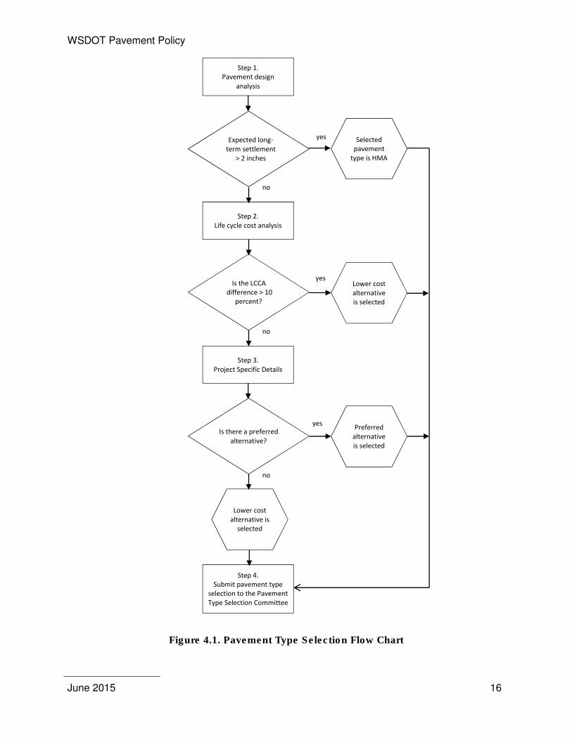
There are three primary areas that must to be addressed to select a pavement type: pavement
design analysis, life cycle cost analysis, and project specific details. Each of these areas can
have a significant impact on the selected pavement type and requires a detailed analysis. The
overall process is shown in Figure 4.1. The specific requirements for each step and examples
are included in Appendix 3 through 8.
Pavement type selection is applicable to all new alignments including ramps, roundabouts,
collector-distributors, acceleration-deceleration lanes, and existing pavement reconstruction on
interstate, principal arterials, and any other roadway that may benefit from this analysis.
Pavement type selection is not necessary for chip seal surfaced roadways. For mainline
widening, if the selected pavement type is the same pavement type as the existing, then a
pavement type selection is not required. When comparing life cycle costs of the different
alternatives, the comparison must be based on the total costs, which include initial construction,
maintenance, rehabilitation, and user costs.
Pavement types shall be considered equal if the total cost difference (including all the costs
listed above) for the higher cost alternative does not exceed the lower cost alternative by more
than 10 percent. Otherwise, the lower cost alternative shall be selected.
4.1 APPLICATION OF PAVEMENT TYPE SELECTION
The following is a list of considerations for new construction or reconstruction of mainline,
ramps, collector-distributors, roundabouts, acceleration-deceleration lanes, intersections and
shoulders.
� Mainline new and reconstructed: A pavement type selection must be completed on all
mainline pavements that are more than ½ lane mile in length or more than $0.5 million
except those highways designated as having or is planned to have a chip seal surface.
For roadway segments shorter in length or lower in cost, Contact the HQ Pavements
Office for further direction on the need to conduct a pavement type selection.
WSDOT Pavement Policy
June 2015 14
� Ramps: Both PCC and HMA shall be considered for ramps with mature geometrics
(where lane configuration or right of way restricts the expansion of the roadway
footprint), high traffic and high truck percentages.
� Collector-Distributors: Design collector-distributors similar to ramps above.
� Roundabouts: Construct roundabouts with the same pavement type as the intersecting
roadway. If the proposed pavement type is different from the mainline pavement type a
life cycle cost justification is required.
� Acceleration-Deceleration Lanes: Treat the same as collector-distributors.
� Intersections: Most intersections will not require an analysis separate from the rest of
the highway. Intersections with chronic rutting should be examined in detail to determine
the nature and cause of the rutting and whether alternate pavement types should be
considered. Contact the HQ Pavements Office for further guidance and direction
regarding options for addressing chronic intersection rutting.
� Shoulders: The choice of HMA or PCCP shoulders for new rigid pavement is dependent
upon the future use of the roadway structure. Life cycle investments, not only present
worth but also the initial capitalization costs must be considered and approved by the
HQ Pavements Office. Future traffic in this context implies either diverted traffic,
construction or the shoulder will become a primary lane of traffic at a future date.
o Shoulders Will Not be Used for Future Traffic: Shoulders for this application
are designed as flexible pavement. Usually, concrete shoulders will not be used
under these conditions. If a concrete shoulder option is pursued, a life cycle cost
analysis must be performed. The concrete shoulder pavement section must
match the mainline thickness and be placed over granular base. Shoulder widths
must follow the Design Manual requirements.
o Shoulders Will be Used for Future Traffic: Shoulders for this application are
designed as full depth HMA or PCC, built to match the mainline traffic lanes.
These shoulders are constructed using the same full depth section as the
mainline, with lane widths following the Design Manual requirements.
o Urban Roadways: It is recommended that shoulders be constructed with PCC,
tied to the adjacent lane and doweled.
WSDOT Pavement Policy
June 2015 15
4.2 SUBMITTAL PROCESS
The pavement type selection, including all applicable subsections (pavement design analysis,
cost estimate and life cycle cost analysis, including the results of the RealCost evaluation
including all applicable RealCost input files and project specific details shall be submitted
electronically to the Pavement Design Engineer at the HQ Pavements Office. The pavement
type selection analysis shall be reviewed and distributed to the Pavement Type Selection
Committee (Appendix 3 through 7) for approval. The report submittal shall include detailed
explanation of the various applicable items, as those outlined above, that supports the selection
of the recommended pavement type.
WSDOT Pavement Policy
June 2015 16
Figure 4.1. Pavement Type Selection Flow Chart
Selected
pavement
type is HMA
Step 2.
Life cycle cost analysis
Step 1.
Pavement design
analysis
Is the LCCA
difference > 10
percent?
Expected long-
term settlement
> 2 inches
Lower cost
alternative
is selected
Step 3.
Project Specific Details
Is there a preferred
alternative?
Preferred
alternative
is selected
Lower cost
alternative is
selected
Step 4.
Submit pavement type
selection to the Pavement
Type Selection Committee
yes
yes
yes
no
no
no
WSDOT Pavement Policy
June 2015 17
5. NEW PAVEMENT DESIGN
5.1 DESIGN PROCEDURES
"New pavement design" shall include reconstructed as well as new pavement structures.
The primary design procedure for pavement structures is the AASHTO Guide for Design of
Pavement Structures (1993); however, the Mechanistic-Empirical Pavement Design Guide
(MEPDG version 1.0) along with WSDOT pavement historical data and experience was used in
the development and validation of the design tables. Minimum layer thicknesses are controlled
by requirements contained in Section 9.2.3. Requirements for maximum lift thicknesses are
specified within WSDOT's Standard Specifications for Road, Bridge, and Municipal Construction
(which also describes other pavement material requirements such as gradation, fracture,
cleanliness, etc.).
5.2 DETERMINATION OF FLEXIBLE PAVEMENT LAYER THICKNESSES
5.2.1 INTRODUCTION
Layer thicknesses and total pavement structure over subgrade soils for flexible pavements are
based on four criteria:
� Depth to provide a minimum level of serviceability for the design period recognizing that
periodic surface renewals may be needed,
� Depth to prevent excessive rutting,
� Depth to prevent premature fatigue cracking of the HMA layers, and
� Depth to provide adequate frost depth protection.
5.2.2 MAINLINE ROADWAY
The structural design of mainline flexible pavements can be broadly divided into those with
fewer than 1,000,000 ESALs for the design period and those greater than 1,000,000 ESALs.
Those pavements with AADT less than 10,000 shall be considered for a chip seal wearing
course over CSBC. For pavements with ESALs less than 1,000,000 and ADT levels greater
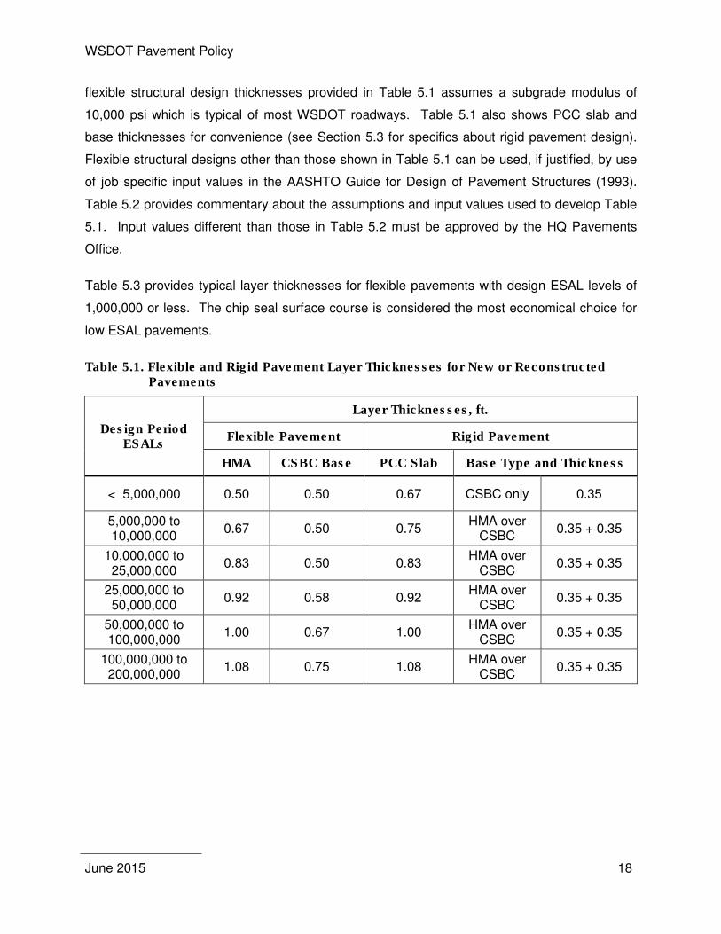
than 10,000 both chip seal and HMA surfaces shall be considered. Table 5.1 provides typical
layer thicknesses for HMA surfaced flexible pavements for ESAL levels up to 200 million. The
WSDOT Pavement Policy
June 2015 18
flexible structural design thicknesses provided in Table 5.1 assumes a subgrade modulus of
10,000 psi which is typical of most WSDOT roadways. Table 5.1 also shows PCC slab and
base thicknesses for convenience (see Section 5.3 for specifics about rigid pavement design).
Flexible structural designs other than those shown in Table 5.1 can be used, if justified, by use
of job specific input values in the AASHTO Guide for Design of Pavement Structures (1993).
Table 5.2 provides commentary about the assumptions and input values used to develop Table
5.1. Input values different than those in Table 5.2 must be approved by the HQ Pavements
Office.
Table 5.3 provides typical layer thicknesses for flexible pavements with design ESAL levels of
1,000,000 or less. The chip seal surface course is considered the most economical choice for
low ESAL pavements.
Table 5.1. Flexible and Rigid Pavement Layer Thicknesses for New or Reconstructed Pavements
Design Period ESALs
Layer Thicknesses, ft.
Flexible Pavement Rigid Pavement
HMA CSBC Base PCC Slab Base Type and Thickness
< 5,000,000 0.50 0.50 0.67 CSBC only 0.35
5,000,000 to 10,000,000
0.67 0.50 0.75 HMA over
CSBC 0.35 + 0.35
10,000,000 to 25,000,000
0.83 0.50 0.83 HMA over
CSBC 0.35 + 0.35
25,000,000 to 50,000,000
0.92 0.58 0.92 HMA over
CSBC 0.35 + 0.35
50,000,000 to 100,000,000
1.00 0.67 1.00 HMA over
CSBC 0.35 + 0.35
100,000,000 to 200,000,000
1.08 0.75 1.08 HMA over
CSBC 0.35 + 0.35
WSDOT Pavement Policy
June 2015 19
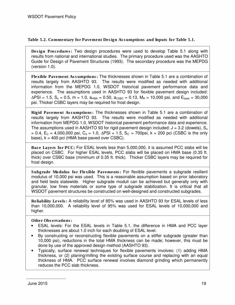
Table 5.2. Commentary for Pavement Design Assumptions and Inputs for Table 5.1.
Design Procedures: Two design procedures were used to develop Table 5.1 along with results from national and international studies. The primary procedure used was the AASHTO Guide for Design of Pavement Structures (1993). The secondary procedure was the MEPDG (version 1.0).
Flexible Pavement Assumptions: The thicknesses shown in Table 5.1 are a combination of results largely from AASHTO 93. The results were modified as needed with additional information from the MEPDG 1.0, WSDOT historical pavement performance data and experience. The assumptions used in AASHTO 93 for flexible pavement design included:
∆PSI = 1.5, So = 0.5, m = 1.0, aHMA = 0.50, aCSBC = 0.13, MR = 10,000 psi, and Ebase = 30,000 psi. Thicker CSBC layers may be required for frost design.
Rigid Pavement Assumptions: The thicknesses shown in Table 5.1 are a combination of results largely from AASHTO 93. The results were modified as needed with additional information from MEPDG 1.0, WSDOT historical pavement performance data and experience. The assumptions used in AASHTO 93 for rigid pavement design included: J = 3.2 (dowels), So = 0.4, EC = 4,000,000 psi, Cd = 1.0, ∆PSI = 1.5, SC’ = 700psi, k = 200 pci (CSBC is the only base), k = 400 pci (HMA base paved over CSBC).
Base Layers for PCC: For ESAL levels less than 5,000,000, it is assumed PCC slabs will be placed on CSBC. For higher ESAL levels, PCC slabs will be placed on HMA base (0.35 ft. thick) over CSBC base (minimum of 0.35 ft. thick). Thicker CSBC layers may be required for frost design.
Subgrade Modulus for Flexible Pavements: For flexible pavements a subgrade resilient modulus of 10,000 psi was used. This is a reasonable assumption based on prior laboratory and field tests statewide. Higher subgrade moduli can be achieved but generally only with granular, low fines materials or some type of subgrade stabilization. It is critical that all WSDOT pavement structures be constructed on well-designed and constructed subgrades.
Reliability Levels: A reliability level of 85% was used in AASHTO 93 for ESAL levels of less than 10,000,000. A reliability level of 95% was used for ESAL levels of 10,000,000 and higher.
Other Observations:
• ESAL levels: For the ESAL levels in Table 5.1, the difference in HMA and PCC layer thicknesses are about 1.0 inch for each doubling of ESAL level.
• By constructing or reconstructing flexible pavements on a stiffer subgrade (greater than 10,000 psi), reductions in the total HMA thickness can be made; however, this must be done by use of the approved design method (AASHTO 93).
• Typically, surface renewal techniques for flexible pavements involves: (1) adding HMA thickness, or (2) planing/milling the existing surface course and replacing with an equal thickness of HMA. PCC surface renewal involves diamond grinding which permanently reduces the PCC slab thickness.
WSDOT Pavement Policy
June 2015 20
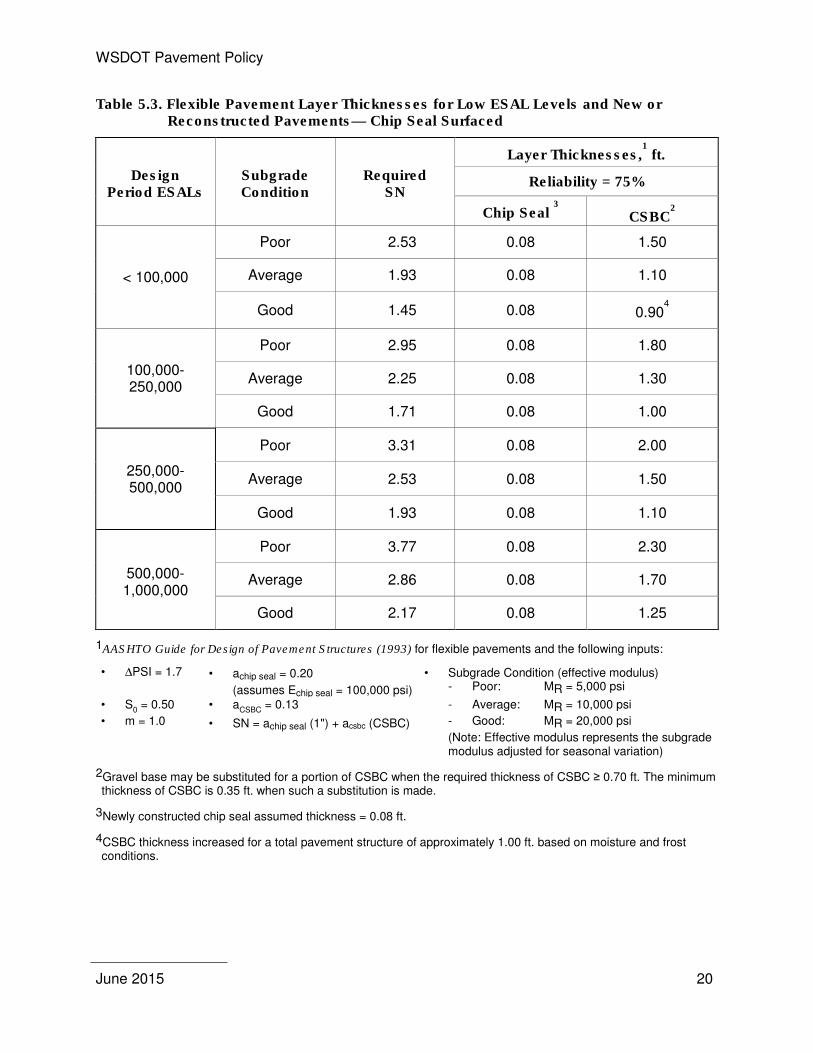
Table 5.3. Flexible Pavement Layer Thicknesses for Low ESAL Levels and New or Reconstructed Pavements— Chip Seal Surfaced
Design Period ESALs
Subgrade Condition
Required SN
Layer Thicknesses,1 ft.
Reliability = 75%
Chip Seal 3 CSBC
2
< 100,000
Poor 2.53 0.08 1.50
Average 1.93 0.08 1.10
Good 1.45 0.08 0.904
100,000-250,000
Poor 2.95 0.08 1.80
Average 2.25 0.08 1.30
Good 1.71 0.08 1.00
250,000-500,000
Poor 3.31 0.08 2.00
Average 2.53 0.08 1.50
Good 1.93 0.08 1.10
500,000-1,000,000
Poor 3.77 0.08 2.30
Average 2.86 0.08 1.70
Good 2.17 0.08 1.25
1AASHTO Guide for Design of Pavement Structures (1993) for flexible pavements and the following inputs:
• ∆PSI = 1.7 • achip seal = 0.20
(assumes Echip seal = 100,000 psi)
• Subgrade Condition (effective modulus) - Poor: MR = 5,000 psi
• S0 = 0.50 • a
CSBC = 0.13 - Average: MR = 10,000 psi
• m = 1.0 • SN = achip seal (1") + acsbc (CSBC) - Good: MR = 20,000 psi
(Note: Effective modulus represents the subgrade modulus adjusted for seasonal variation)
2Gravel base may be substituted for a portion of CSBC when the required thickness of CSBC ≥ 0.70 ft. The minimum thickness of CSBC is 0.35 ft. when such a substitution is made.
3Newly constructed chip seal assumed thickness = 0.08 ft.
4CSBC thickness increased for a total pavement structure of approximately 1.00 ft. based on moisture and frost conditions.
WSDOT Pavement Policy
June 2015 21
5.2.3 RAMPS, FRONTAGE ROADS, AND WEIGH STATIONS
Ramps shall be designed for the expected traffic.
Frontage roads and weigh stations that are maintained by WSDOT shall be designed in
accordance with the AASHTO Guide for Design of Pavement Structures (1993). Frontage
roads that counties and cities are to accept and maintain but constructed by WSDOT shall be
designed to the standards of the accepting agency.
The total depth of the pavement section must be at least one-half of the maximum expected
depth of freezing when the subgrade is classified as a frost susceptible soil. The depth of
expected freeze can be based on calculations by use of the design freezing index or the field
data gathered by WSDOT during the winter of 1949-1950 (see appendix 2).
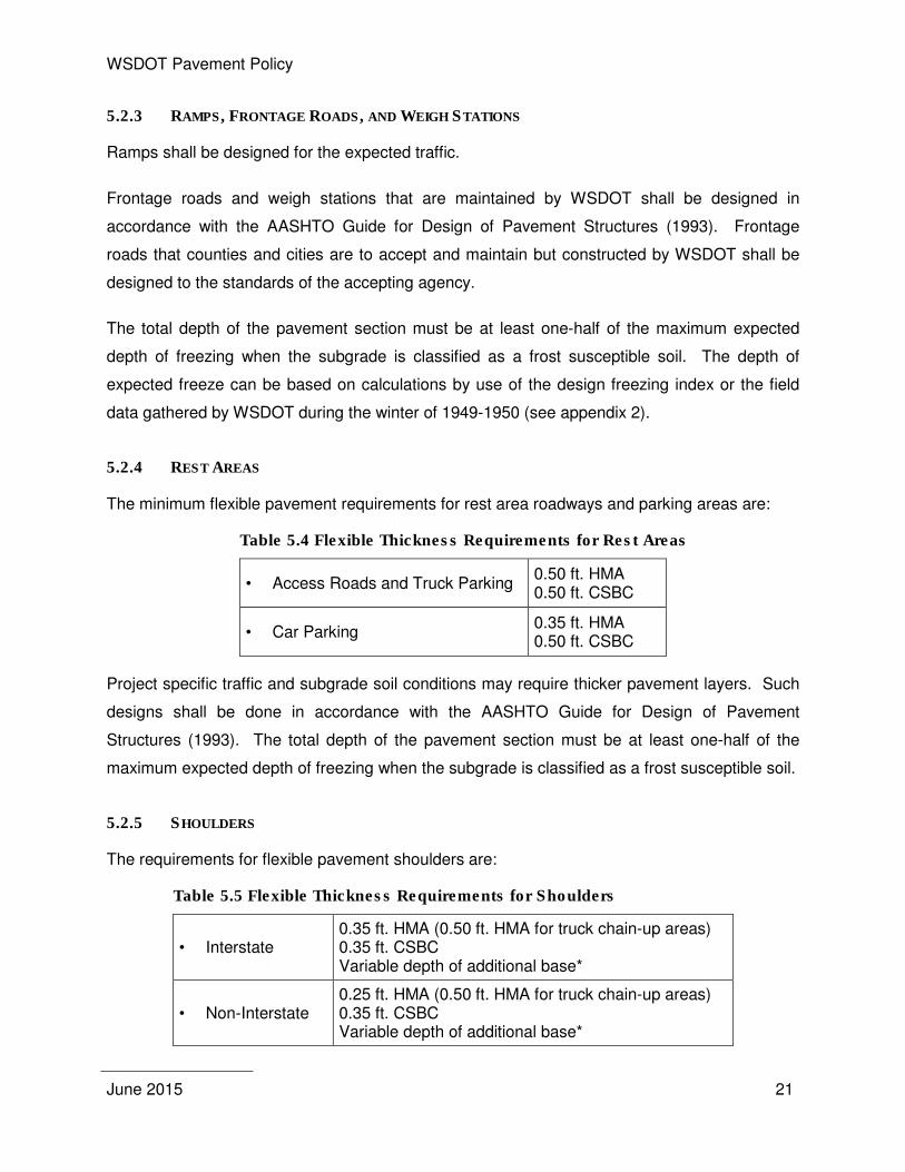
5.2.4 REST AREAS
The minimum flexible pavement requirements for rest area roadways and parking areas are:
Table 5.4 Flexible Thickness Requirements for Rest Areas
• Access Roads and Truck Parking 0.50 ft. HMA 0.50 ft. CSBC
• Car Parking 0.35 ft. HMA 0.50 ft. CSBC
Project specific traffic and subgrade soil conditions may require thicker pavement layers. Such
designs shall be done in accordance with the AASHTO Guide for Design of Pavement
Structures (1993). The total depth of the pavement section must be at least one-half of the
maximum expected depth of freezing when the subgrade is classified as a frost susceptible soil.
5.2.5 SHOULDERS
The requirements for flexible pavement shoulders are:
Table 5.5 Flexible Thickness Requirements for Shoulders
• Interstate 0.35 ft. HMA (0.50 ft. HMA for truck chain-up areas) 0.35 ft. CSBC Variable depth of additional base*
• Non-Interstate 0.25 ft. HMA (0.50 ft. HMA for truck chain-up areas) 0.35 ft. CSBC Variable depth of additional base*
WSDOT Pavement Policy
June 2015 22
* The Gravel Base or CSBC shall extend to the bottom of the mainline base course.
Design HMA shoulder pavement thickness the same as the travelled way in the following
locations:
• Ramps
• Intersections where turning movements will result in vehicles tracking on the shoulders
• Areas designated for shoulder driving
• Slow vehicle turnouts
• WSP Shoulder weighing/inspection sites
Pavement thicknesses different than described above require approval by the HQ Pavements
Office.
The total depth of the pavement section must be at least one-half of the maximum expected
depth of freezing when the subgrade is classified as a frost susceptible soil.
5.3 DETERMINATION OF RIGID PAVEMENT LAYER THICKNESSES
The principal type of rigid pavement used by WSDOT in the past, and will be continued for the
foreseeable future, is a plain, jointed PCC pavement with dowel bars.
All new construction, reconstruction and lane widening shall be conducted such that the
concrete lane edges and the lane stripe are congruent, except when the outside lane is paved
14 feet in width in which case the lane shall be striped at 12 feet (see 9.3.1).
5.3.1 INTRODUCTION
Based on the past performance of PCC pavement on the state route system under a variety of
traffic conditions (various ESAL levels) and on city streets (such as the City of Seattle), it is
advisable to use slab thicknesses of 0.67 feet or greater even if the ESAL levels would suggest
that lesser slab thicknesses would be adequate. A slab thickness of 0.67 feet or greater
provides some assurance of adequate long-term performance given that other design details
are adequately accommodated.
WSDOT Pavement Policy
June 2015 23
5.3.2 MAINLINE ROADWAY
Table 5.1 provides layer thicknesses for rigid pavements for ESAL levels up to 200 million. The
PCC thicknesses included in Table 5.1 are supported on granular or HMA base depending upon
the ESAL level. Table 5.2 provides commentary about the assumptions and input values used
to develop the rigid pavement layer thicknesses.
PCC slab thicknesses other than those shown in Table 5.1 can be used if justified by project
specific input values used in the AASHTO Guide for Design of Pavement Structures (1993).
Such input values must be approved by the HQ Pavements Office.
The total depth of the pavement section must be at least one-half of the maximum expected
depth of freezing when the subgrade is classified as a frost susceptible soil.
5.3.3 PCC INTERSECTIONS AND ROUNDABOUTS
The same requirements apply as described in paragraph 5.3.2. Jointing details, PCC
construction limits and specifics concerning roundabout construction requires approval by the
HQ Pavements Office.
5.3.4 RAMPS, FRONTAGE ROADS, AND WEIGH STATIONS
The same requirements apply to rigid pavement ramps and frontage roads as for flexible
pavements as noted in Paragraph 5.2.3.
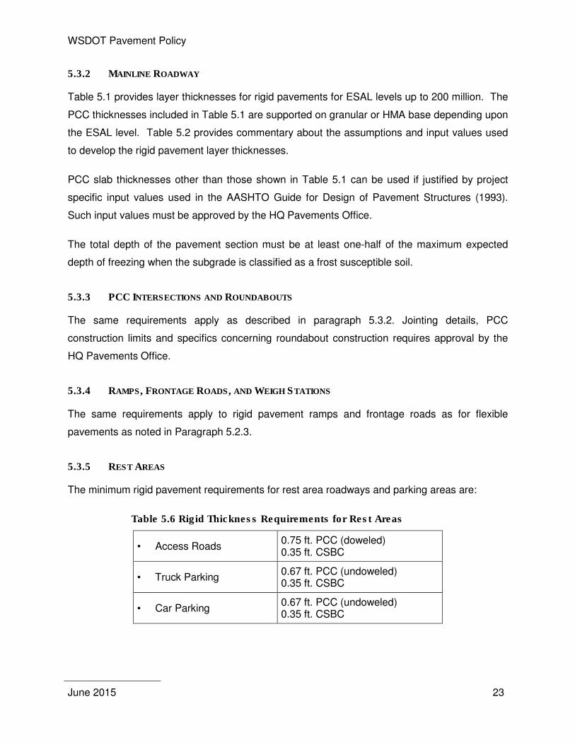
5.3.5 REST AREAS
The minimum rigid pavement requirements for rest area roadways and parking areas are:
Table 5.6 Rigid Thickness Requirements for Rest Areas
• Access Roads 0.75 ft. PCC (doweled) 0.35 ft. CSBC
• Truck Parking 0.67 ft. PCC (undoweled) 0.35 ft. CSBC
• Car Parking 0.67 ft. PCC (undoweled) 0.35 ft. CSBC
WSDOT Pavement Policy
June 2015 24
Project specific traffic and subgrade soil conditions may require thicker pavement layers. Such
designs shall be done in accordance with the AASHTO Guide for Design of Pavement
Structures (1993).
The total depth of the pavement section must be at least one-half of the maximum expected
depth of freeze when the subgrade is classified as a frost susceptible soil.
5.3.6 SHOULDERS
When shoulders will not be used for future traffic, the concrete shoulder pavement section must
match the mainline thickness and be placed over granular base.
Shoulders that will carry future traffic are designed as full depth HMA or PCC, built to match the
mainline traffic lanes. These shoulders are constructed using the same full depth section as the
mainline, with lane widths following the Design Manual requirements.
5.4 PERMEABLE PAVEMENTS
Effective stormwater management is a high priority for WSDOT. Conventional impermeable
pavement does not allow water to penetrate the ground where it can be naturally filtered and
cleaned before entering streams and underground water supplies. Permeable pavements are a
potential method of managing stormwater that eliminates the need of a separate collection,
treatment and storage system. Water simply flows through the permeable pavement and
directly into the underlying soil.
5.4.1 INTRODUCTION
Permeable pavement suits new construction of very low volume, slow speed locations with
infrequent truck traffic.
5.4.2 APPLICATION
Permeable pavements shall be considered and used for the following applications:
• Sidewalks, bicycle trails, community trail/pedestrian path systems, or any pedestrian-
accessible paved areas (such as traffic islands)
• Light vehicle access areas such as maintenance/enforcement areas on divided
highways
WSDOT Pavement Policy
June 2015 25
• Public and municipal parking lots, including perimeter and overflow parking areas
• Driveways
5.4.3 PAVEMENT STRUCTURE
Permeable pavements include an engineered structure consisting of permeable hot mix asphalt
or concrete wearing surface, aggregate storage layer and a subgrade soil with sufficient
infiltration capability to drain water from the aggregate storage layer.
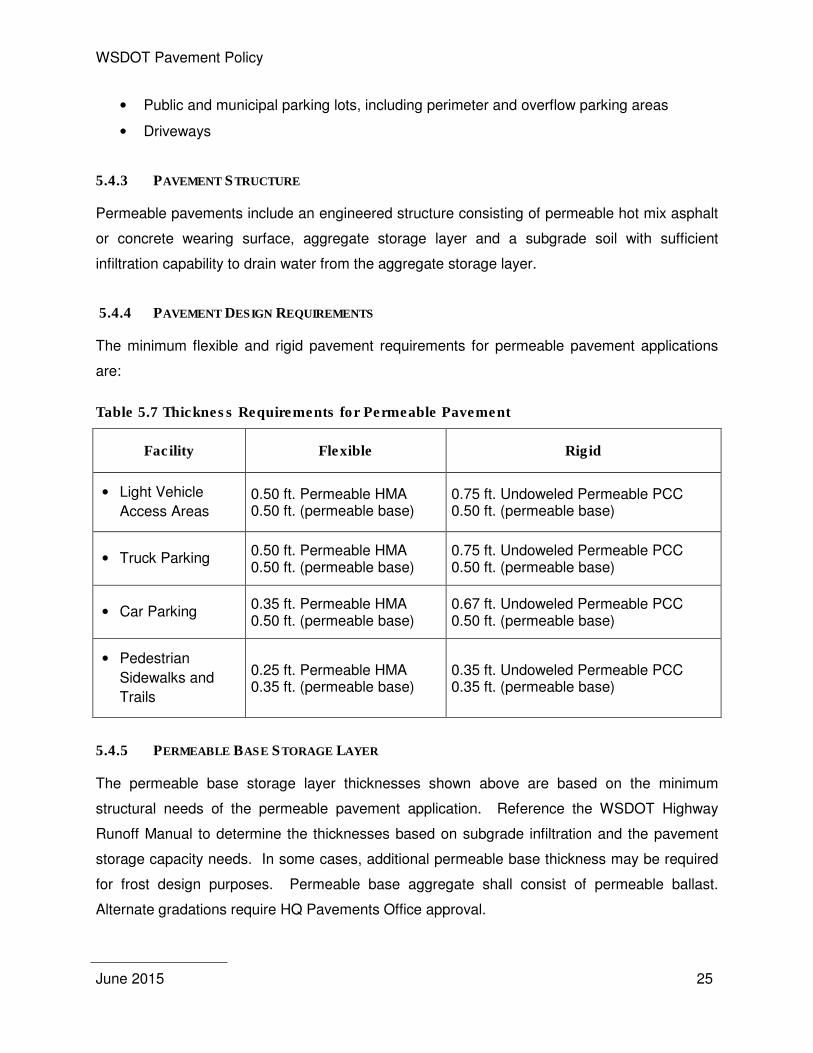
5.4.4 PAVEMENT DESIGN REQUIREMENTS
The minimum flexible and rigid pavement requirements for permeable pavement applications
are:
Table 5.7 Thickness Requirements for Permeable Pavement
Facility Flexible Rigid
• Light Vehicle
Access Areas 0.50 ft. Permeable HMA 0.50 ft. (permeable base)
0.75 ft. Undoweled Permeable PCC 0.50 ft. (permeable base)
• Truck Parking 0.50 ft. Permeable HMA 0.50 ft. (permeable base)
0.75 ft. Undoweled Permeable PCC 0.50 ft. (permeable base)
• Car Parking 0.35 ft. Permeable HMA 0.50 ft. (permeable base)
0.67 ft. Undoweled Permeable PCC 0.50 ft. (permeable base)
• Pedestrian
Sidewalks and
Trails
0.25 ft. Permeable HMA 0.35 ft. (permeable base)
0.35 ft. Undoweled Permeable PCC 0.35 ft. (permeable base)
5.4.5 PERMEABLE BASE STORAGE LAYER
The permeable base storage layer thicknesses shown above are based on the minimum
structural needs of the permeable pavement application. Reference the WSDOT Highway
Runoff Manual to determine the thicknesses based on subgrade infiltration and the pavement
storage capacity needs. In some cases, additional permeable base thickness may be required
for frost design purposes. Permeable base aggregate shall consist of permeable ballast.
Alternate gradations require HQ Pavements Office approval.

WSDOT Pavement Policy
June 2015 26
WSDOT Pavement Policy
June 2015 27
6. PAVEMENT REHABILITATION
If a pavement section reaches a point where preservation is no longer cost effective,
rehabilitation will be required to restore its structural capacity. Employing a rehabilitation
strategy that takes advantage of the remaining structure in the existing pavement is usually
more economical than reconstruction. Rehabilitation methods detailed below that re-use the
remaining structure of the existing pavement should be considered before reconstructing a
pavement. A life cycle cost analysis of the viable alternatives is required to determine if one of
these methods or reconstruction is the best option. Alternatives other than those listed here
may also be considered with the approval of the HQ Pavements Office. Use a 50-year design
life for design of rehabilitations.
National guidelines have been developed (with help from WSDOT) for designing long-lasting
structural enhancements that incorporate existing pavements. These guidelines are available in
a final report on SHRP2 Project R23 and through a web based program called rePave. It is
recommended that rePave be used for preliminary project scoping. The final structural design
shall be in coordination with and approved by the HQ Pavements Office.
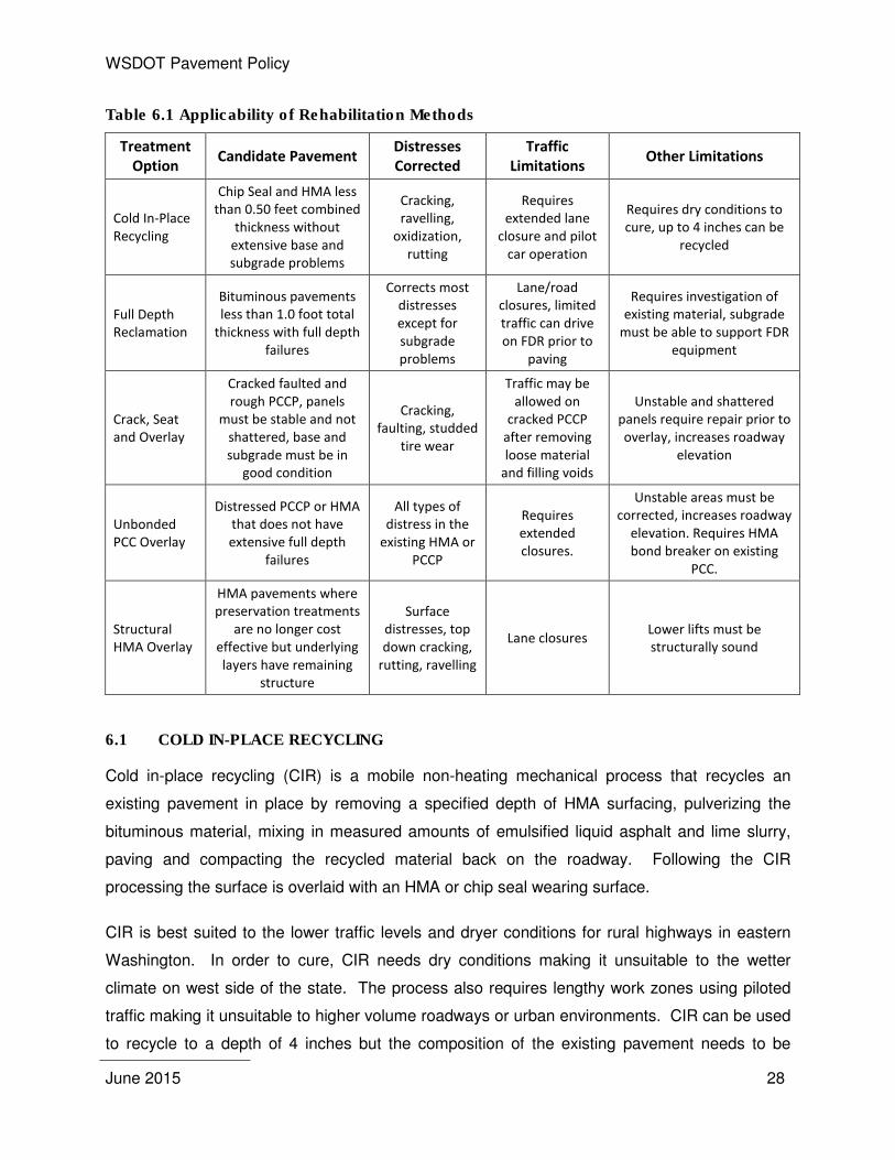
A summary of the applicability of the rehabilitation methods is shown in Table 6.1
WSDOT Pavement Policy
June 2015 28
Table 6.1 Applicability of Rehabilitation Methods
Treatment
Option Candidate Pavement
Distresses
Corrected
Traffic
Limitations Other Limitations
Cold In-Place
Recycling
Chip Seal and HMA less
than 0.50 feet combined
thickness without
extensive base and
subgrade problems
Cracking,
ravelling,
oxidization,
rutting
Requires
extended lane
closure and pilot
car operation
Requires dry conditions to
cure, up to 4 inches can be
recycled
Full Depth
Reclamation
Bituminous pavements
less than 1.0 foot total
thickness with full depth
failures
Corrects most
distresses
except for
subgrade
problems
Lane/road
closures, limited
traffic can drive
on FDR prior to
paving
Requires investigation of
existing material, subgrade
must be able to support FDR
equipment
Crack, Seat
and Overlay
Cracked faulted and
rough PCCP, panels
must be stable and not
shattered, base and
subgrade must be in
good condition
Cracking,
faulting, studded
tire wear
Traffic may be
allowed on
cracked PCCP
after removing
loose material
and filling voids
Unstable and shattered
panels require repair prior to
overlay, increases roadway
elevation
Unbonded
PCC Overlay
Distressed PCCP or HMA
that does not have
extensive full depth
failures
All types of
distress in the
existing HMA or
PCCP
Requires
extended
closures.
Unstable areas must be
corrected, increases roadway
elevation. Requires HMA
bond breaker on existing
PCC.
Structural
HMA Overlay
HMA pavements where
preservation treatments
are no longer cost
effective but underlying
layers have remaining
structure
Surface
distresses, top
down cracking,
rutting, ravelling
Lane closures Lower lifts must be
structurally sound
6.1 COLD IN-PLACE RECYCLING
Cold in-place recycling (CIR) is a mobile non-heating mechanical process that recycles an
existing pavement in place by removing a specified depth of HMA surfacing, pulverizing the
bituminous material, mixing in measured amounts of emulsified liquid asphalt and lime slurry,
paving and compacting the recycled material back on the roadway. Following the CIR
processing the surface is overlaid with an HMA or chip seal wearing surface.
CIR is best suited to the lower traffic levels and dryer conditions for rural highways in eastern
Washington. In order to cure, CIR needs dry conditions making it unsuitable to the wetter
climate on west side of the state. The process also requires lengthy work zones using piloted
traffic making it unsuitable to higher volume roadways or urban environments. CIR can be used
to recycle to a depth of 4 inches but the composition of the existing pavement needs to be
WSDOT Pavement Policy
June 2015 29
relatively consistent to avoid difficulties in controlling the emulsion rates. Because CIR is only
able to recycle the surface layers, it is not able to correct deep failures or subgrade problems.
Ideal candidates for CIR are pavements showing distresses from transverse, reflective, or
fatigue cracking, oxidation and raveling within the HMA or HMA/Chip Seal composite layer.
In CIR design, it is desirable to recycle the full depth of the bituminous layers to ensure that any
cracking is eliminated but the base and subgrade must be adequate to support the CIR
equipment. If full depth removal is not possible, at least two thirds of the bituminous layers
should be recycled to prevent any full depth cracks from reflecting into the CIR. Typically 1.5
inches of remaining bituminous material is sufficient to support the CIR train. Core the existing
pavement to ensure that the existing pavement depth is sufficient.
The new pavement structure can be designed using AASHTO Guide for Design of Pavement
Structures (1993) using a 0.30 layer coefficient for the CIR. A reduced structural coefficient
should also be used for any bituminous layer and base remaining after recycling. The HMA
layer placed over CIR typically ranges from 0.15 to 0.25 feet although thicker sections may be
necessary for higher truck traffic. At a minimum a chip seal with two applications of emulsion
and aggregate should be placed over the CIR to prevent ravelling.
6.2 FULL DEPTH RECLAMATION
Full Depth Reclamation (FDR) is a rehabilitation method where the full depth of the existing
bound pavement layers are pulverized and mixed in with the base and subgrade. Stabilization
agents may be added to increase the strength of the reclaimed mixture as well as additional
aggregate as needed. FDR is capable of reclaiming the existing pavement structure up to a
depth of one foot in a single pass but the total bituminous layer depth needs to be at least one
inch less than the total reclaimed depth to allow the reclaimer to operate effectively.
Although a limited amount of traffic can be allowed on FDR prior to paving, FDR is most
appropriate to roadways where longer closures can be accommodated. Since the full depth of
the pavement layer is reclaimed, FDR is appropriate to repair any distress other than subgrade
problems.
Many different materials have been used as stabilizing agents with asphalt emulsions and
portland cement the most common. FDR requires the sampling of materials from the roadway
in order to determine moisture content and test trial mixtures in the lab in order to determine a
WSDOT Pavement Policy
June 2015 30
suitable application rate for the stabilizing agents. In pavement design, a structural coefficient of
0.20 is typically used with the AASHTO Guide for Design of Pavement Structures (1993).
6.3 CRACK, SEAT AND OVERLAY
Cracking and seating existing PCCP reduces the effective panel size from WSDOT’s standard
12 feet by 15 feet panel to blocks of pavement between 2 and 6 feet on a side with the general
goal of square blocks. The smaller effective panel size distributes tensile stresses over more
joints reducing the strain and resulting reflection cracking in an HMA overlay. Crack, seat and
overlay is applicable to concrete pavement that has reached the end of its useful life and
pavement preservation techniques are no longer cost effective. The crack and seat process
requires a subgrade that is in relatively good condition and there should not be a large number
of panels that have settled or are shattered. Settled or shattered panels need to be replaced
with HMA prior to overlaying.
In order to insure long pavement life, the minimum overlay thickness should be 0.65 feet of
HMA. Thicker overlays may be designed depending on traffic loading, subgrade and site
conditions. The overlay can be designed using AASHTO Guide for Design of Pavement
Structures (1993). A modulus of 75,000 psi is recommended for the crack and seated PCCP
(rePave). Crack, seat and overlay will increase the roadway grade by the thickness of the
overlay. Undercrossings with insufficient vertical clearance and mainline bridges will require
removal of the existing PCCP and replacement with new full depth HMA pavement sections to
maintain the required grade.
6.4 UNBONDED CONCRETE OVERLAY
An unbonded concrete overlay consists of a new concrete pavement placed over an existing
HMA or PCCP pavement. By using the remaining structure of the existing HMA or PCCP, the
thickness of the new PCCP overlay can be designed thinner than if it was a new pavement
section. If the existing pavement is PCCP, a separation layer needs to be placed between the
old and new pavement. The separation layer isolates the new concrete overlay from the
existing pavement allowing the unbonded overlay to be placed over existing pavement that is in
poor condition. Only unstable areas of the existing pavement need to be repaired prior to the
overlay.
WSDOT Pavement Policy
June 2015 31
The thickness of an unbonded overlay may be designed using AASHTO Guide for Design of
Pavement Structures (1993). Adjustments should be made to the resulting concrete
thicknesses to account for the conservatively thick sections generated by AASHTO Guide for
Design of Pavement Structures (1993). This can be done by adjusting the resulting thickness
generated by AASHTO Guide for Design of Pavement Structures (1993) to a thickness that is in
proportion to Table 5.1.
An unbonded overlay will increase the roadway elevation by the thickness of the overlay and the
separation layer. Undercrossings with insufficient vertical clearance and mainline bridges will
require removal of the existing PCCP and replacement new full depth concrete pavement
sections to maintain the required grade.
6.5 HMA STRUCTURAL OVERLAY
An HMA structural overlay may be considered when pavement preservation treatments are no
longer a cost effective alternative to preserve the pavement until the next rehabilitation period.
Structural overlays should only be used where past pavement performance has shown that the
pavement structure is insufficient. Pavement that is performing adequately should not receive
a structural overlay simply because an analysis says that the structure is not sufficient for the
future ESALs. Pavements that have little or no remaining structure are not good candidates for
a structural overlay and another treatment should be considered.
Thickness design of structural overlays should be performed using AASHTO Guide for Design
of Pavement Structures (1993) by applying a reduced structural value for existing layers that are
to remain or by using DARWin’s overlay design module. Prior to constructing the overlay,
structural distresses in the existing pavement need to be repaired. This may include milling to
remove top down cracking or pavement repair to fix deeper structural problems.

WSDOT Pavement Policy
June 2015 32
WSDOT Pavement Policy
June 2015 33
7. PAVEMENT PRESERVATION
Pavement preservation extends the service life of an existing pavement. The pavement
preservation strategy selected should extend the pavement service life at the lowest life cycle
cost.
The pavement preservation strategy selected depends on the type of pavement (flexible or rigid)
and the pavement condition. Roadways with annual average daily traffic (AADT) less than
10,000 are designated chip seal routes and preservation of these routes should follow Section
7.1 Chip Seals. Exceptions (such as paving through small cities, intersections with a significant
number of turning movements, locations with limited chip seal use, etc.) to this policy are
evaluated on a case-by-case basis. The AADT criterion of 10,000 does not imply that chip
seals cannot or should not be placed on higher AADT routes. If the Region requests placing a
chip seal on a higher volume HMA route, the request shall be made based on a pavement
analysis and documented in the Regions Pavement Design Report. Non chip seal routes will
generally be preserved with the same pavement type as the existing pavement. Approval for
application of chip seals on routes with AADT greater than 10,000 and other exceptions requires
approval from the State Pavement Engineer.
The primary method of preserving an HMA pavement is a thin HMA inlay or overlay.
Preservation treatments such as crack sealing, patching and chip sealing should be used to
extend the time between thin inlays/overlays on all HMA routes.
7.1 CHIP SEALS
Chip seals are an effective method of preserving pavements on low volume roadways at a low
life cycle cost. In order to realize the low life cycle cost of a chip seal, work performed to correct
deficiencies in the existing pavement needs to be kept to the minimum required to provide
serviceable pavement over the life of the chip seal.
WSDOT Pavement Policy
June 2015 34
7.1.1 PAVEMENT DESIGN
The design period for a chip seal is typically six to eight years. Regions may use any design
method that gives acceptable results. Chip seal types other than those provided in Section 5-02
of the Standard Specifications must be approved through HQ Pavements Office.
7.1.2 PREPARATION OF EXISTING PAVEMENT
Deficiencies in the existing pavement that may affect the performance of the chip seal will need
to be corrected prior to placing the chip seal. Corrective work should be limited to that
necessary to preserve the roadway and provide a serviceable pavement for the life of the chip
seal.
7.1.2.1 Prelevel
The use of prelevel prior to placement of a chip seal is limited strictly to spot improvements such
as broken shoulders or distressed pavement and is limited to 70 tons of HMA per lane mile.
Increased prelevel quantities require approval by the HQ Pavements Office. Reasons for the
increased prelevel quantities include:
1. Removal of hazardous “spot” locations, e.g., ponding areas or to restore proper
pavement drainage at a specific location.
2. Correction of deficient superelevation or cross slope when the deficiency is the cause of
operational problems as determined from an accident history analysis.
3. Pavement rutting specifically identified (rutting greater than ⅜ inch).
When any prelevel is warranted it must be clearly documented in the pavement design and
carefully detailed in the contract PS&E so that the use is clearly apparent to the contractor and
the construction Project Engineer.
7.1.2.2 Pavement Repair
Pavement repair on chip seal projects should address areas of load related failure of the
existing pavement such as depressed alligator cracked areas. Pavement repair depth should
be kept to the minimum required to restore the load carrying capacity of the pavement.
7.1.2.3 Crack Sealing
Chip seal performance can be enhanced by sealing cracks prior to the chip seal application.
Where hot poured crack sealing products have been used, cracking has been delayed and in
WSDOT Pavement Policy
June 2015 35
some cases eliminated thus extending the life of the chip seal. Hot poured products are
typically used for cracks between ¼ and 1 inch in width. Sand slurry emulsions are typically
more economical for crack widths one inch or greater. Minor cracks will be addressed by the
application of emulsified asphalt during placement of the chip seal. Cracks on chip seal routes
should be sealed one year in advance of the chip seal placement to allow crack sealing
materials to cure.
7.1.3 DESIGN CONSIDERATIONS
7.1.3.1 Mainline Shoulders
Shoulders on chip seal roadways do not require treatment as often as the pavement in the
travel lane. Shoulders shall only receive a chip seal if warranted by pavement condition.
7.1.3.2 Recessed Lane Markers and Rumble Strips
Evaluate the existing pavement thickness and condition to determine if rumble strips can be
installed on chip seal roadways without causing premature damage to the pavement. If
recessed lane markers or rumble strips are used, the existing chip seal surfacing should have a
minimum thickness of 0.25 ft. which can include any combinations of chip seal and HMA
applications.
Grinding rumble strips on chip seal roadways exposes the previous chip seal layers. Exposure
to moisture accumulation and freezing and thawing often leads to delamination. To reduce the
possibility of delamination at rumble strip locations, rumble strips shall be ground prior to the
chip seal application.
Roadways to receive subsequent chip seals shall be evaluated to determine if the depth of the
remaining rumble strips are adequate to allow an additional chip seal. Previous WSDOT
experience has shown that a chip seal can be placed over existing rumble strips once and still
be effective. Where rumble strips need to be reground, preleveling may be required to remove
distressed pavement and provide sufficient pavement structure.
7.1.3.3 Chip Seals over New HMA Overlays
Chip seal need is generally triggered by one of three conditions:
• Friction: Where a chip seal is placed for friction purposes, the need shall be clearly
substantiated by the Region Materials Engineer with supporting friction data;
WSDOT Pavement Policy
June 2015 36
• Surface Distress: For routes with surface distress as determined by the WSPMS; and
• New HMA: There is strong evidence that application of a chip seal over a new HMA
overlay reduces the aging of the HMA binder which reduces top down cracking. This
practice of placing a chip seal on HMA within one year following construction of the HMA
overlay has been examined by WSDOT with positive findings.
7.2 HOT MIX ASPHALT
Pavement with relatively thin HMA layers (less than six inches) tend to crack from the bottom up
requiring replacement of the entire HMA layer at the end of the pavement’s life. WSDOT has
found that cracking in HMA pavement layers thicker than six inches tends to be from the top of
the pavement layer down. Since bottom up cracking is minimal, preservation of these thicker
HMA sections involves correcting the top down cracking and other surface distresses leaving
the underlying pavement structure intact. If properly maintained the underlying pavement
structure can last 50 years or more resulting in a low life cycle cost. HMA preservation should
focus on preserving this underlying pavement structure.
7.2.1 PAVEMENT DESIGN
HMA preservation is intended to be non-structural which only requires replacement of the top
layer of HMA to remove aged related top-down surface cracking. The thickness of these inlays
will be the minimum depth required to remove the majority of the top-down cracking. If
additional structure is required, HMA overlay design can be accomplished either by use of the
mechanistic-empirical based scheme used in the Everpave© computer program or the AASHTO
Guide for Design of Pavement Structures (1993), Part III, Chapter 5. The Everpave© program is
for use with flexible pavements. The AASHTO procedure can be applied to either flexible or
rigid pavement structures. The design period for HMA preservation thickness design for thin
inlays/overlays is 15 years.
The Roadway Paving Program cost estimate is based on a pavement inlay depth of 0.15 foot.
The required depth for an HMA inlay shall be as noted in the Pavement Design Report. Every
effort should be made to keep inlays to the 0.15 foot depth; however, in some cases this may
not be possible due to existing structural conditions. Pavement designs greater than 0.15 feet
require a detailed analysis, including a pavement design, justifying the increase in thickness.
WSDOT Pavement Policy
June 2015 37
7.2.1.1 Granular Overlays (Cushion Courses)
The granular overlay system (often referred to as a "cushion course") is an alternative type of
overlay for rehabilitating mostly low volume, rural roads (this does not necessarily imply a low
number of ESALs). The overlay consists of a layer of densely compacted, crushed rock (CSBC)
overlain by a generally thin surface layer. The surfacing depth can vary depending on local
conditions and requirements; however, the CSBC depth shall not exceed 0.50 feet in order to
achieve the maximum structural benefit.
7.2.1.2 Subgrade Soils
Subgrade soil resilient modulus for thin (0.15’ or less) overlays or inlays can be obtained from
existing soil data or a cursory evaluation of soil conditions. When thicker sections are called for
to increase pavement structure, additional soils investigation or deflection survey should be
conducted to validate the need for additional structure.
A pavement deflection survey is performed on selected projects by the HQ Pavements Office.
This survey shall be conducted before the Pavement Design Report to aid the Region Materials
Engineer with coring and sampling of each project. The deflection survey shall be conducted,
when possible, either in late fall or early spring. The Region Materials Engineer shall coordinate
with the HQ Pavements Office so that most of the deflection surveys are conducted during one
time period each year. After conducting the deflection surveys, the HQ Pavements Office will
report the results of the survey to the Region Materials Engineer.
7.2.2 PREPARATION OF EXISTING PAVEMENT
In order for an HMA thin inlay/overlay to perform well, specific distresses in the existing
pavement need to be corrected. There may be multiple methods to address a distressed
pavement dependant on the type and severity of distress. For example, cracking can be
repaired by full depth pavement repair or planing depending on the depth of the cracking.
Various distress repair and overlay strategies should be evaluated to determine which is most
cost effective.
7.2.2.1 Prelevel
The use of prelevel prior to placement of an overlay is strictly limited to the correction of safety
related deficiencies unless otherwise stated in the Pavement Design Report. Safety-related
uses of prelevel are as follows:
WSDOT Pavement Policy
June 2015 38
• To remove hazardous “spot” locations, e.g., ponding areas or to restore proper
pavement drainage at a specific location.
• To correct deficient superelevation or cross slope when the deficiency is the cause of
operational problems as determined from an accident history analysis.
• To address pavement rutting specifically identified in the Pavement Design (rutting of
less than ⅜ inch will generally be addressed with the overlay).
A shallow grind, with a depth equal to the depth of the ruts is an alternative to prelevel. The
cost of grinding versus prelevel should be evaluated when prelevel is needed.
When prelevel is warranted as outlined above, it must be clearly documented in the pavement
design and carefully detailed in the contract PS&E so that the use is clearly apparent to the
contractor and the construction Project Engineer.
7.2.2.2 Crack Sealing
The item “crack sealing” will only be used when specified in the Pavement Design Report.
Crack sealing will be done only on cracks ¼ inch and wider, see Standard Specification 5-
04.3(5)C. Minor cracks will be addressed by the use of tack coat. Hot poured products may be
used for cracks between ¼ and 1 inch in width. Sand slurry emulsions are typically more
economical for filling cracks one inch or greater.
7.2.2.3 Pavement Repair
As WSDOT’s HMA pavements become thicker, due to successive overlays, failures tend to be
limited to the surface course. Distress in thicker HMA pavements (generally greater than six
inches) typically occurs as top down cracking. Top down cracks often penetrate only the
wearing surface of a roadway and do not affect the aggregate base or subgrade. Options for
rehabilitating pavements with top down cracking include planing and inlaying or overlaying
depending upon the extent and depth of the distress. In most cases, pavement coring will easily
identify the depth of the required pavement repair.
Thinner pavements (generally less than six inches) can experience distress throughout the HMA
thickness and sometimes into the aggregate base and subgrade. In these cases, full depth
replacement of the HMA may be warranted, however, the repair of the pavement failures can
range from removing the entire pavement section to only the depth of the last overlay. Coring
shall be performed to determine the depth of required repair. Depending on the distress,
WSDOT Pavement Policy
June 2015 39
removal and replacement of aggregate base and subgrade may be necessary. It is important
that the Project Offices work closely with the Region Materials Office to determine the cause
and extent of the pavement failures.
While pavement repair is preferred to totally remove the distressed pavement, increasing the
overlay depth in localized areas can also be considered if conditions warrant. The additional
cost of the overlay, however, shall be compared to the cost of providing pavement repair.
7.2.3 DESIGN CONSIDERATIONS
7.2.3.1 Mainline Thin Mill and Fill Preservation
Pavement preservation that requires the milling of mainline and inlaying the milled thickness
with HMA should extend a minimum of 0.5 foot (preferably a foot) into the shoulder. The
extension of the milling into the shoulder moves the resulting longitudinal joint away from traffic
and extends pavement life. If rumble strips are distressed, extend the milling to include the
rumble strip.
A major advantage of a mill and fill versus an overlay is that a mill and fill allows paving of only
the lanes needing immediate preservation. An overlay requires paving of the full width of the
roadway regardless of condition often resulting in overlaying of pavement which is not currently
in need of preservation. In order to minimize cost, inlay only lanes presently in need of
preservation on multilane roadways. Similarly, only mill and fill turn lanes, parking strips and
shoulders if warranted by the pavement condition.
7.2.3.2 Mainline Shoulders
Mainline shoulders will generally require a thin inlay/overlay every other rehabilitation cycle.
When shoulders do require treatment, it is often only the portion nearest the travel lane that
needs preservation. In these cases, only paving a four or five foot strip nearest fog stripe
should be considered.
7.2.3.3 Fog Sealing
Shoulders shall be fog sealed based on the Region Materials Office recommendations. Lanes
paved with dense graded HMA are typically not fog sealed unless an open texture forms shortly
after construction. Fog seals to address this issue have been shown to be effective in helping to
reduce the excessive surface voids.
WSDOT Pavement Policy
June 2015 40
7.2.3.4 Pavement Markings, Recessed Lane Markers and Rumble Strips
Recessed lane markers and methyl methacrylate striping, thermoplastic stop bars, arrows, or
other coated materials shall be removed prior to placement of the HMA overlay.
Rumble strips on shoulders may be overlaid with a minimum depth of 0.15 feet HMA as long as
there is no shift in the existing lane configuration that will cause the wheel path to cross over the
underlying rumble strips. If this is the case, reflection of the underlying rumble strip will occur.
On HMA inlay projects where the rumble strips need replacement, the width of the inlay can be
increased outside of the fog line to include the rumble strip area.
Rumble strips on shoulders that will carry traffic as a detour shall be preleveled or ground and
inlayed with a minimum depth of 0.15 feet HMA. A typical option is to plane and inlay a three
foot width from the fog line towards the shoulder edge.
Rumble strips located between directional traffic shall be preleveled or removed by planing and
inlayed. The centerline joint should be offset so that the rumble strips are not ground into the
lower density HMA near the joint where practical.
HMA shoulders shall be compacted to the same requirements as the traveled lanes per
WSDOT Standard Specification 5-04.3(10) where freeze thaw, heavy moisture or chronic
rumble strip distress is present.
7.2.3.5 Increased Milling Depth for Delaminations
Pavement thicknesses shall not be arbitrarily increased based on perceived concerns that the
underlying layers will delaminate on a rotomill and inlay project. A thicker lift can be approved,
however, cores obtained at a minimum of 0.25 mile intervals must substantiate that a
delaminated layer exists.
7.2.3.6 Tack Coat
A tack coat is required between all HMA layers (new construction and overlay).
7.2.3.7 Correcting Shoulder Slopes
Roadways with a 0.02 ft./ft. cross slope on the lanes and 0.05 ft./ft. on the shoulders may be
corrected provided the shoulder width is four feet or less. On roadways with shoulders wider
than four feet, the correction will be deferred depending on funding.
WSDOT Pavement Policy
June 2015 41
7.2.3.8 Removal of Open Graded Pavements Prior to Overlays
Open-graded pavements shall be removed prior to overlaying with dense-graded HMA.
Removal of the open-graded asphalt layer is necessary to avoid stripping of the open-graded
layer once a new layer of HMA is placed. On lower volume roadways, cold in-place recycling of
an OGEAP layer is an acceptable rehabilitation alternative.
On planing and inlay projects, where only the travelled lanes are preserved, open-graded
pavements may remain on the shoulders for many thin inlay/overlay cycles. However, where
there is potential for the existing shoulder to become a travelled lane, the open-graded asphalt
layer shall be removed prior to any future overlays.
7.2.3.9 HMA Surfaced Bridge Decks
Most bridges with existing HMA surfaces should be paved at the same time as the adjacent
roadway. Even if the HMA on the bridge is in relatively good condition, it is often more cost
effective to pave the bridge at the same time as the roadway rather than to pave it later under a
standalone project.
Removal of some of the existing HMA prior to paving may be necessary to prevent excess dead
load caused by the build-up of HMA layers. To ensure adequate compaction, paving depths
should follow the minimum provided in Section 9.2.3. See the Bridge Condition Report or
contact the Bridge and Structures Office for specific milling and overlay depth requirements.
7.3 PORTLAND CEMENT CONCRETE PAVEMENTS
Dowel bar retrofit, localized panel replacements (as necessary) and diamond grinding have
proven to be effective PCC pavement preservation methods in Washington State. These
preservation options restore transverse joint load transfer, replace PCC panels that have a high
risk of failure, and provide a smooth driving surface.
Preservation of PCC pavement is limited to dowel bar retrofits, diamond grinding and replacing
distressed panels. HMA overlays without pre-treating the existing PCC are susceptible to
reflection cracking and are not an approved method of rehabilitating PCC pavements.
Dowel bar retrofits can be effective since WSDOT did not generally place dowels in PCC
pavement up until 1993. Dowel bars placed in the wheel paths have been shown to significantly
restore load transfer and hence reduce reoccurring faulting. Dowel bar retrofits can be
WSDOT Pavement Policy
June 2015 42
expected to perform adequately for about 10 to 15 years. Following this, it is common WSDOT
experience to observe accelerated slab deterioration.
7.3.1 PAVEMENT DESIGN
PCCP preservation does not increase the structural load carrying capacity of the pavement
(other than to improve load transfer across joints) so no specific thickness design requirements
apply.
7.3.2 DISTRESS CORRECTION
The focus of PCCP preservation is to correct specific pavement distress and thus extend the life
of the pavement and improve serviceability.
7.3.2.1 Faulting/Load Transfer
Improvement of load transfer should be accomplished by retrofitting the pavement with dowel
bars. Ideal candidate projects for dowel bar retrofitting are those PCC roadways that are 25 to
35 years old and have fault measurements less than ⅛ inch. Pavements that are 35 years or
older and have faulting greater than ½ inch shall be considered for diamond grinding only
without dowel bar retrofitting.
7.3.2.2 Panel Replacements
Panels cracked into three or more pieces or settled by more than ½ inch should be replaced.
The minimum panel replacement length is 6 feet. The panel concrete depth generally matches
the existing pavement. Thicker replacement panels require approval by the HQ Pavements
Office.
7.3.2.3 Diamond Grinding
Roughness caused by studded tires or faulting should be corrected by diamond grinding. Make
the final pass of grinding parallel to the direction of travel for the completed project.
Contractors have requested additional compensation on several projects based on the ruts in
the field being deeper than the rut depths indicated in the contract. When cement concrete
pavement grinding is required, there needs to be a method for the contractor to accurately
assess the rut depth. One method that appears to have been successful on several projects is
to provide a time when the contractors can access the site during lane closures.
WSDOT Pavement Policy
June 2015 43
The accuracy of rut depth data collected by the HQ Pavements Office is only sufficient for
system wide analysis and is not accurate enough for bidding purposes. If rut depth data
collected by the HQ Pavements office is provided to the contractor it must be made clear the
data is for information only.
7.3.2.4 Shoulders
Shoulders should be evaluated for preservation at the time of PCCP preservation. Diamond
grinding of the adjacent PCCP often requires the grinding of existing shoulder to prevent leaving
a vertical edge between the lane and shoulder.
7.3.2.5 Hot Mix Asphalt Overlays of PCCP
Overlaying HMA on PCC pavements includes a range of rehabilitation strategies that must be
considered including the condition of the existing PCC and whether the PCC is doweled or non-
doweled.
Non-Doweled Concrete Pavements: HMA overlays without pre-treating the existing PCC are
susceptible to reflection cracking and are not an approved method of rehabilitating PCC
pavements. Pre-treatment of non-doweled pavement may consist of panel replacements, dowel
bar retrofitting or a combination of both. In some instances cracking and seating and overlaying
may be a suitable option.
Doweled Concrete Pavements: Diamond grinding can become problematic for PCC pavements
with dowels as each successive diamond grind reduces concrete cover above the dowels. PCC
pavements with less than three inches of concrete cover over the dowel bars should not be
ground. Overlaying doweled PCC with HMA requires approval from the HQ Pavements Office.
Normally non-doweled pavements will require a thicker overlay as compared to doweled
pavements. In either case, overlaying PCC with HMA requires approval from the HQ
Pavements Office.
7.4 OTHER PAVEMENT PRESERVATION TREATMENTS
The bulk of WSDOT flexible pavement preservation consists of single chip seals and HMA
inlays. These strategies have proven to be a cost effective means to preserve highways in
Washington State. However; there are many other preservation treatments that are used to

WSDOT Pavement Policy
June 2015 44
successfully preserve pavements. These treatments may be considered when selecting a
preservation treatment. The Table 7.1 details the applicability of some of these treatments:
Table 7.1 Applicability of Preservation Treatments
Treatment
Option Candidate Pavement Distress Corrected Traffic Limitations Other
Hot Chip Seal
Chip seal projects where
time to open to traffic or
loose chips is a factor
Same as chip seal
Lane closures, can
be opened to
traffic sooner than
a conventional
chip seal
Reduces the amount
of loose chips
Double Chip
Seal
Flushed roadways or
where a more durable chip
seal is needed
Same as chip seal Same as chip seal Two chip sizes are
often used
Hot In-Place
Recycling
HMA pavements that do
not have deep failure or
materials problems
Surface cracking,
ravelling
Lengthy lane
closures required
during paving
Best suited for
roadways without
sharp curves, few side
roads or driveways
and few overhead
utilities, not suitable
for wearing surface
7.4.1 HOT CHIP SEALS
Hot chip seals consist of an application of asphalt binder followed by application of aggregate
similar to a standard chip seal. Unlike a standard chip seal, the aggregate is pre-coated with
asphalt at an asphalt plant before it is placed on the roadway. Pre-coating the chips improves
the binding to the roadway and reduces dust allowing the roadway to be opened to traffic
sooner than a conventional chip seal. A hot chip seal should be considered on higher volume
roadways to allow earlier opening to traffic without excessive loose chips.
7.4.2 DOUBLE CHIP SEAL
A double chip seal is essentially two single chip seals, one placed on top of the other. The chip
size of the second application is often smaller than the first allowing for improved “key in” of the
chips. WSDOT has successfully constructed a double chip seal using the same aggregate for
both applications. Double chip seals are often used where damage by truck traffic is an issue.
WSDOT has used a double chip seal to mitigate a flushing HMA pavement.
WSDOT Pavement Policy
June 2015 45
7.4.3 HOT IN-PLACE RECYCLING
Hot in-place recycling (HIR) employs a train of specialized equipment to remove, process and
repave the existing pavement in one pass. The HIR recycling train is slower and less
manoeuvrable than conventional paving equipment. Roadways with sharp curves or many side
streets and driveways that must be kept open to traffic may not be good candidates for HIR.
The HIR equipment also needs sufficient space off the roadway at about one to two mile
intervals to park the HIR equipment between shifts. HIR is capable of recycling the top two
inches of the pavement at a constant width of about 12 feet. The constant width makes it
difficult to use HIR on wider travel lanes or roadways where there are many turn lanes that
require preservation. The addition of recycling agents and aggregate allow some improvement
of the recycled HMA but existing pavement with severe materials problems like stripping should
be avoided. Paving fabrics and an excess of rubberized crack sealers can also be problematic.
HIR can be considered as an alternate to an inlay where the roadway geometrics are
compatible with the HIR equipment. HIR is susceptible to ravelling and is not suitable for use as
a final wearing surface. A surface treatment or HMA overlay is required to be placed over all
HIR pavements.

WSDOT Pavement Policy
June 2015 46
WSDOT Pavement Policy
June 2015 47
8. PREVENTIVE PRESERVATION
Preventive Preservation is anticipated, planned work designed to extend the service life of a
roadway 1-6 years and to maximize the time between Capital Preservation Projects (thin mill
and inlay, overlay and chip seal projects). Preventive preservation work should follow the
requirements of Instructional Letter IL 4077 Bituminous Pavement Asset Management and the
Integrated Approach to Pavement Preservation.

WSDOT Pavement Policy
June 2015 48
WSDOT Pavement Policy
June 2015 49
9. DESIGN DETAILS
This section provides design standards that are relevant to all phases of pavement design: new
pavement, rehabilitation and preservation. These requirements are to be followed when
designing the applicable pavement type or situation.
9.1 GENERAL DESIGN DETAILS
9.1.1 TRAFFIC DATA
Traffic data from the Transportation Information and Planning Support (TRIP’s) traffic file will be
used on most projects, as contained in the Washington State Pavement Management System
(WSPMS). Where the HQ Pavements Office or Region Materials Engineer believes the data in
the file is not adequate, a special traffic count on the project can be requested to verify the data.
If the region does not have personnel to conduct the traffic counts, the Transportation Data
Office shall be contacted for assistance.
9.1.2 SUBGRADE DRAINAGE
For a pavement section to perform well, a system must be provided to avoid prolonged periods
of high water content in the base and subgrade. Excess water under the pavement weakens
subgrade and unbound base layers, increases the potential for frost heave and can result in
pumping with the associated faulting and loss of support. WSDOT’s standard practice for
providing subgrade drainage is to use a layer of CSBC under the bound pavement layers. For
most pavements in Washington, a CSBC layer is adequate to remove any water that enters
through cracks and openings in the pavement surface.
Unless the underlying soil is highly permeable, a path needs to be provided for water in the
CSBC layer to exit the pavement structure. The preferred method is to daylight the CSBC in the
side slope or ditch. If daylighting the CSBC is not possible, an underdrain parallel to the
roadway needs to be installed adjacent to the paved shoulder and below the CSBC layer. The
underdrain should be connected to the storm drainage system or routed to another suitable
discharge location. Underdrain systems must receive periodic maintenance to remain effective.
WSDOT Pavement Policy
June 2015 50
9.2 HMA DESIGN DETAILS
9.2.1 ESAL LEVEL FOR DEVELOPING HMA MIX DESIGN
For HMA roadways the HMA mix designs ESALs shall be based on 15 years.
In order to reduce the likelihood of stripping, the mix design ESALs for HMA under PCCP shall
be 0.29 million.
HMA shoulders on PCCP roadways are often required to go for long intervals between
repaving. To produce a durable mix, the preferred mix design ESALs are 0.29 million. If there
is other HMA work on the project and the quantity of shoulder HMA is small, consideration
should be given to using the same mix design ESALs as the other HMA on the project.
9.2.2 PG BINDER SELECTION CRITERIA
Binder selection for HMA mixes is based on the PG grading system and the following criteria:
• Base PG grades with no adjustment for traffic speed or ESAL level
o Western Washington: PG 58-22*
o Eastern Washington: PG 64-28
• Adjustment for traffic speed
o Standing (0 to 10 mph): Increase PG high temperature by 2 grades (12°C)
o Slow (10 to 45 mph): Increase PG high temperature by 1 grade (6°C)
o Free flow (45+ mph): No adjustment
• Adjustment for traffic loading (15 year ESALs)
o ≤ 10,000,000 ESALs: No adjustment
o 10,000,000 to 30,000,000 ESALs: Consider an increase in the PG high
temperature by 1 grade (6°C)
o > 30,000,000 ESALs: Increase PG high temperature by 1 grade (6°C)
The maximum increase in the PG high temperature for any combination of conditions will not
exceed a 2 grade increase (or 12°C) over the base PG grade.
The high temperature PG may be reduced for lifts other than the wearing course.
* PG58-22 is not available in Washington. PG64-22 should be specified when the binder selection criteria indicates PG58-22.
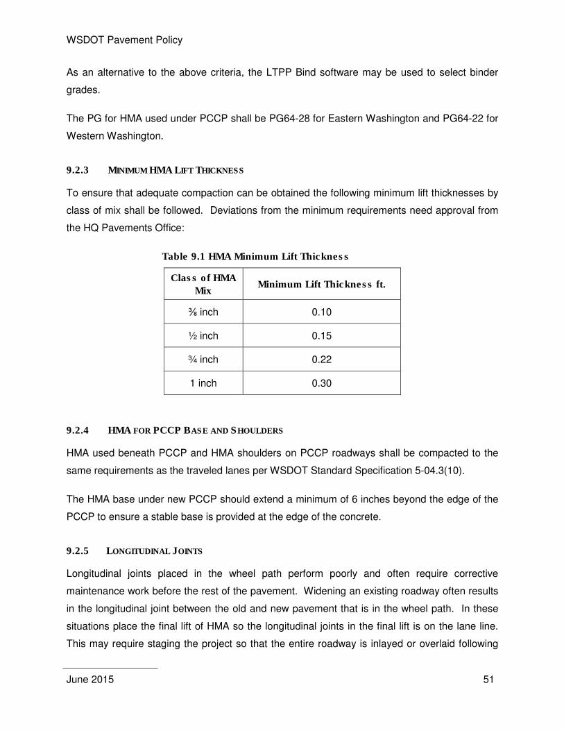
WSDOT Pavement Policy
June 2015 51
As an alternative to the above criteria, the LTPP Bind software may be used to select binder
grades.
The PG for HMA used under PCCP shall be PG64-28 for Eastern Washington and PG64-22 for
Western Washington.
9.2.3 MINIMUM HMA LIFT THICKNESS
To ensure that adequate compaction can be obtained the following minimum lift thicknesses by
class of mix shall be followed. Deviations from the minimum requirements need approval from
the HQ Pavements Office:
Table 9.1 HMA Minimum Lift Thickness
Class of HMA
Mix Minimum Lift Thickness ft.
⅜ inch 0.10
½ inch 0.15
¾ inch 0.22
1 inch 0.30
9.2.4 HMA FOR PCCP BASE AND SHOULDERS
HMA used beneath PCCP and HMA shoulders on PCCP roadways shall be compacted to the
same requirements as the traveled lanes per WSDOT Standard Specification 5-04.3(10).
The HMA base under new PCCP should extend a minimum of 6 inches beyond the edge of the
PCCP to ensure a stable base is provided at the edge of the concrete.
9.2.5 LONGITUDINAL JOINTS
Longitudinal joints placed in the wheel path perform poorly and often require corrective
maintenance work before the rest of the pavement. Widening an existing roadway often results
in the longitudinal joint between the old and new pavement that is in the wheel path. In these
situations place the final lift of HMA so the longitudinal joints in the final lift is on the lane line.
This may require staging the project so that the entire roadway is inlayed or overlaid following
WSDOT Pavement Policy
June 2015 52
completion of the widening or grinding a portion of the existing pavement so the full width of the
final lift in the new lane can be paved in one pass.
9.2.6 MOUNTAIN PASS PAVING CRITERIA
WSDOT has experienced repeated HMA pavement with poor performance or failures on
mountain passes. To ensure the highest level of performance the following design/construction
elements are required:
• Utilize a Material Transfer Vehicle (MTV) such as a Shuttle Buggy
• Use a notch wedge joint for all longitudinal joints with an unconfined edge
• Place longitudinal joint adhesive on the vertical face of the notch wedge joint
• Compact shoulders to the same requirements as the traveled lanes per WSDOT
Standard Specification 5-04.3(10)
• Extend paving limits to one foot beyond the edge stripe or outside the existing rumble
strips
• Utilize trucks with tarps during the placement of HMA
• Require cyclic density testing or the use of a Pave-IR system to eliminate cyclic
temperature differentials in the HMA
• Consider the use of HMA Class 3/8 inch for the wearing course.
9.3 CEMENT CONCRETE PAVEMENT DESIGN DETAILS
9.3.1 USE OF WIDENED OUTSIDE LANE
If shoulders are constructed with HMA, at a minimum, the right most lane (truck lane) shall be
constructed 14 feet wide and striped at 12 feet.
9.3.2 DOWEL BARS AND TIE BARS
Newly constructed rigid pavements shall use corrosion resistant dowel bars conforming to
Standard Specification 9-07.5(2) (stainless steel, zinc clad etc.). Dowel bar selection criteria for
mainline roadway, roundabouts, intersections and shoulders are detailed in Appendix 1.
PCCP shoulders shall be tied in all cases and doweled if expected to carry future traffic.
WSDOT Pavement Policy
June 2015 53
Dowels shall be used for the entire transverse joint where a widened PCCP lane (see 9.3.1) is
constructed in the right shoulder. The dowel bars should be placed starting 1.0 foot from the
longitudinal joint between the concrete panel and the HMA shoulder.
9.3.3 SHOULDERS
The concrete placed on shoulders shall be placed concurrent with the outside lane.
9.3.4 JOINTING PLANS
The Standard Plans provide jointing details for mainline PCCP travel lanes and shoulders.
Additional jointing details are required to be included in the contract plans for jointing layouts
that are not covered in the Standard Plans such as intersections, roundabouts and tapers.
Include proposed joint locations, joint type and isolation joints for utilities. Identify where dowel
bars and tie bars are required in the jointing plans. Submit jointing plans to the HQ Pavements
office for approval with the pavement design report or during PS&E development.
The jointing plan included in the contract documents provides a baseline for pavement
construction but there are often alternative joint locations that will provide equivalent pavement
performance. Contractors are encouraged to propose alternate jointing plans to improve
constructability. Alternate jointing proposals are approved by the HQ Pavements Office.
9.3.5 INTERSECTIONS LIMITS
The limits for reconstruction with PCC shall be determined based on an evaluation of the
existing pavement conditions. The area of pavement rutting or distress shall be limited to the
vehicle start and stop areas. The major arterial approach legs to intersections may require PCC
from 200 to 500 feet (Uhlmeyer, 2003) back from the crosswalk (Figure 9.1).
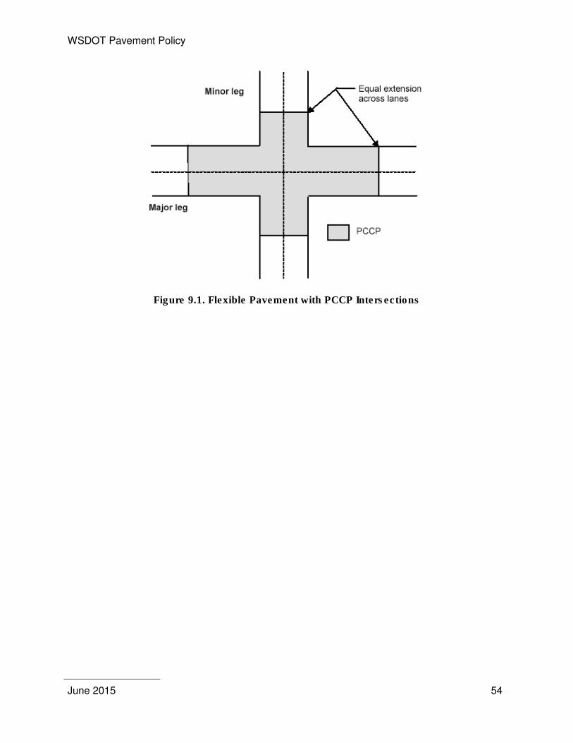
WSDOT Pavement Policy
June 2015 54
Figure 9.1. Flexible Pavement with PCCP Intersections
WSDOT Pavement Policy
June 2015 55
10. PAVEMENT DESIGN REPORT
A Pavement Design Report is required for all HMA and PCC preservation, rehabilitation,
reconstruction and new construction projects, and is recommended for chip seal overlays where
structural problems are evident. The Region Materials Engineer will prepare the report for
review by the HQ Pavements Office. The report will summarize the existing pavement and site
conditions, include discussion of special features or problems, and provide pavement
design/rehabilitation requirements.
A Pavement Design Report is optional if all pavement work is incidental to other work on the
project provided the new pavement structure is at least equivalent to the existing structure.
Examples of incidental pavement work include removing and replacing pavement within the
limits of structure excavation or increasing the pavement thickness at bridge ends to match into
a bridge overlay. A Pavement Design Report is also not required if all of the pavement work on
the project is temporary and will be removed as part of the project. If a Region opts to prepare a
Pavement Design Report, an information copy should be sent to the HQ Pavement Office so it
can be scanned and archived.
A Pavement Design Report will generally consist of four elements: a description of the project,
an evaluation to the conditions at the project site, the pavement thickness design and the
specific design details. Some elements that are specific to pavement preservation and
rehabilitation will not be needed in Pavement Design Reports that address the design of new
pavement only. Each element is described further in the sections that follow.
10.1 PROJECT DESCRIPTION
Items that need to be included are: the description of the project using vicinity maps and plan
views, purpose of project, present and future lane configuration, status and scope of project,
possible construction contingencies, State Route number, milepost limits, project name, XL, OL
or work order, funding program(s), Project Item Number, funded biennium, and anticipated
construction dates.

WSDOT Pavement Policy
June 2015 56
10.2 SITE EVALUATION
The site evaluation includes specific details of the project that will have an impact on the
pavement design. At a minimum include the following in the Pavement Design Report:
10.2.1 TRAFFIC DATA
Include the ADT and estimated ESALs in the design period for each pavement section in the
design. ESAL data will generally be supplied by WSPMS. An explanation should be included
when other sources of ESAL data are used in the design.
10.2.2 CLIMATE CONDITIONS
Unusual climate conditions such as mountain passes or freeze and thaw conditions that affect
the design should be described.
10.2.3 SUBGRADE SOILS AND GEOLOGY
Describe soil conditions encountered in the project limits including the basis of the subgrade
modulus used in the pavement design in the report. The basis of the subgrade modulus may be
a combination of current or previous soils investigations; previous Pavement Design Reports,
field samples and falling weight deflect meter deflection testing. If a deflection survey was
conducted the results should be included. Include pertinent topographic features as they relate
to subgrade soil changes and pavement performance. Provide documentation of the subgrade
modulus values included in the pavement design.
10.2.4 PAVEMENT CONDITION (PRESERVATION AND REHABILITATION ONLY)
Description and photographs of existing pavement conditions with reference to pavement
distress, subgrade soils, geologic features, drainage, frost distress or traffic. Provide a
summary documenting the HMA and base course thicknesses and the nature of the base and
subgrade soils (as noted in section 7.2.3). HMA core sampling shall be taken within the travel
lanes every 0.25 to 0.50 miles of the projects length in order to provide a mechanistic-empirical
design. Areas of distress that require treatment other than the overall roadway (such as frost
heaves or localized pavement failures caused by weak subgrade) shall also be noted. Include a
table with core location and core condition in the Pavement Design Report along with photos of
distressed cores.
WSDOT Pavement Policy
June 2015 57
10.2.5 DRAINAGE AND WATER CONDITIONS
Drainage and water conditions that affect the pavement design or may affect pavement
performance needs to be explained. Describe pertinent drainage features such as ditches,
subgrade drains, drainage blankets, etc., both functioning and non-functioning. Where wet
subgrades are encountered, moisture contents should be determined.
10.2.6 CONSTRUCTION HISTORY (PRESERVATION AND REHABILITATION ONLY)
Provide a description or layer profile of the pavement structure and limits as they relate to past
contracts.
10.3 PAVEMENT DESIGN
The Pavement Design Report shall include PCC and HMA design thicknesses where new
construction warrants alternate pavement types. The specific design method used in the design
shall be included along with justification of design inputs that are different than required by the
pavement policy. Pavement Designs shall be provided in sufficient detail to develop the
contract plans.
10.4 DESIGN DETAILS
Specific criteria concerning pavement design such as correction of special problems, unique
use of materials or procedures, drainage features, and frost distress corrections shall be
documented including:
10.4.1 MATERIALS
The report should describe material requirements that are not covered by the Standard
Specifications. Explain the use of a PG binder grade other than the base grade for the project
location and include the 15 year design ESALs for HMA mix design. Include state owned
materials sources along with special materials when warranted.
10.4.2 CONSTRUCTION CONSIDERATIONS
Strategies to correct specific types of pavement distress including preleveling, digouts,
subsealing and crack sealing should be included. Items such as project timing, potential
problems with materials sources, etc., should be covered.
WSDOT Pavement Policy
June 2015 58
10.4.3 PCCP JOINTING DETAILS
Any PCCP that requires jointing details other than that shown in the Standard Plans (such as
roundabouts, intersections or non-standard pavement sections) shall be approved by the HQ
Pavements Office.
10.4.4 BRIDGE
The HMA bridge deck rehabilitation treatment option selected for each bridge is to be included
in the Pavement Design Report. Concurrence from the Bridge and Structures office shall be
included if the bridge deck rehabilitation treatment differs from the options listed in the Bridge
Condition Report. Attach a copy of the Bridge Condition Report(s) to the Pavement Design
Report.
10.4.5 SPECIAL FEATURES
Review any unique features pertinent to the project not covered under other topics.
10.5 HQ PAVEMENTS OFFICE PAVEMENT DESIGN REPORT APPROVAL
The HQ Pavements Office reviews and evaluates the final Pavement Design Report prepared
by the Regions for new construction, reconstruction, pavement rehabilitation and pavement
preservation. When necessary, a review comments report is prepared for various requirements
of the project. Generally, concurrence will be provided in a signature and date block provided in
the Region Pavement Design Report.
WSDOT Pavement Policy
June 2015 59
References
Uhlmeyer, J.S. (2003). PCCP Intersections Design and Construction in Washington State, WA-RD 503.2, Washington State Department of Transportation.
rePave, SHRP2 R23 Scoping Methodology including Advanced Renewal Systems, Accessed May 27, 2015, pavementrenewal.org.

WSDOT Pavement Policy
June 2015 60
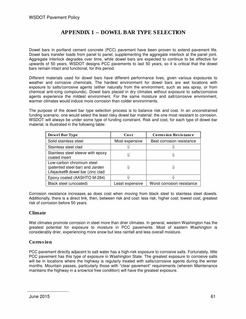
WSDOT Pavement Policy
June 2015 61
APPENDIX 1 – DOWEL BAR TYPE SELECTION
Dowel bars in portland cement concrete (PCC) pavement have been proven to extend pavement life. Dowel bars transfer loads from panel to panel, supplementing the aggregate interlock at the panel joint. Aggregate interlock degrades over time, while dowel bars are expected to continue to be effective for upwards of 50 years. WSDOT designs PCC pavements to last 50 years, so it is critical that the dowel bars remain intact and functional, for this period.
Different materials used for dowel bars have different performance lives, given various exposures to weather and corrosive chemicals. The hardest environment for dowel bars are wet locations with exposure to salts/corrosive agents (either naturally from the environment, such as sea spray, or from chemical anti-icing compounds). Dowel bars placed in dry climates without exposure to salts/corrosive agents experience the mildest environment. For the same moisture and salt/corrosive environment, warmer climates would induce more corrosion than colder environments.
The purpose of the dowel bar type selection process is to balance risk and cost. In an unconstrained funding scenario, one would select the least risky dowel bar material: the one most resistant to corrosion. WSDOT will always be under some type of funding constraint. Risk and cost, for each type of dowel bar material, is illustrated in the following table:
Dowel Bar Type Cost Corrosion Resistance
Solid stainless steel Most expensive Best corrosion resistance
Stainless steel clad ⇓ ⇓
Stainless steel sleeve with epoxy coated insert
⇓ ⇓
Low-carbon chromium steel (patented steel bar) and Jarden Lifejacket® dowel bar (zinc clad dowel bar)
⇓ ⇓
Epoxy coated (AASHTO M-284) ⇓ ⇓
Black steel (uncoated) Least expensive Worst corrosion resistance
Corrosion resistance increases as does cost when moving from black steel to stainless steel dowels. Additionally, there is a direct link, then, between risk and cost: less risk, higher cost; lowest cost, greatest risk of corrosion before 50 years.
Climate
Wet climates promote corrosion in steel more than drier climates. In general, western Washington has the greatest potential for exposure to moisture in PCC pavements. Most of eastern Washington is considerably drier, experiencing more snow but less rainfall and less overall moisture.
Corrosion
PCC pavement directly adjacent to salt water has a high-risk exposure to corrosive salts. Fortunately, little PCC pavement has this type of exposure in Washington State. The greatest exposure to corrosive salts will be in locations where the highway is regularly treated with salts/corrosive agents during the winter months. Mountain passes, particularly those with “clear pavement” requirements (wherein Maintenance maintains the highway in a snow/ice free condition) will have the greatest exposure.
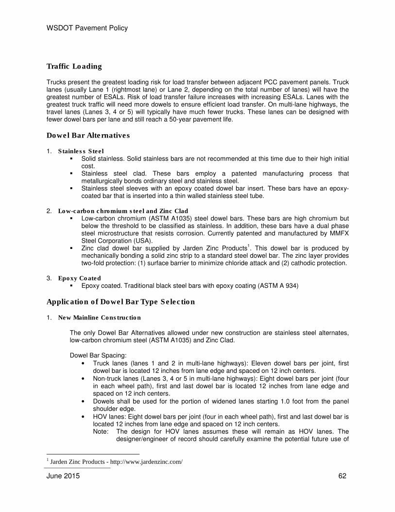
WSDOT Pavement Policy
June 2015 62
Traffic Loading
Trucks present the greatest loading risk for load transfer between adjacent PCC pavement panels. Truck lanes (usually Lane 1 (rightmost lane) or Lane 2, depending on the total number of lanes) will have the greatest number of ESALs. Risk of load transfer failure increases with increasing ESALs. Lanes with the greatest truck traffic will need more dowels to ensure efficient load transfer. On multi-lane highways, the travel lanes (Lanes 3, 4 or 5) will typically have much fewer trucks. These lanes can be designed with fewer dowel bars per lane and still reach a 50-year pavement life.
Dowel Bar Alternatives
1. Stainless Steel � Solid stainless. Solid stainless bars are not recommended at this time due to their high initial
cost. � Stainless steel clad. These bars employ a patented manufacturing process that
metallurgically bonds ordinary steel and stainless steel. � Stainless steel sleeves with an epoxy coated dowel bar insert. These bars have an epoxy-
coated bar that is inserted into a thin walled stainless steel tube.
2. Low-carbon chromium steel and Zinc Clad � Low-carbon chromium (ASTM A1035) steel dowel bars. These bars are high chromium but
below the threshold to be classified as stainless. In addition, these bars have a dual phase steel microstructure that resists corrosion. Currently patented and manufactured by MMFX Steel Corporation (USA).
� Zinc clad dowel bar supplied by Jarden Zinc Products1. This dowel bar is produced by
mechanically bonding a solid zinc strip to a standard steel dowel bar. The zinc layer provides two-fold protection: (1) surface barrier to minimize chloride attack and (2) cathodic protection.
3. Epoxy Coated � Epoxy coated. Traditional black steel bars with epoxy coating (ASTM A 934)
Application of Dowel Bar Type Selection
1. New Mainline Construction
The only Dowel Bar Alternatives allowed under new construction are stainless steel alternates, low-carbon chromium steel (ASTM A1035) and Zinc Clad.
Dowel Bar Spacing: • Truck lanes (lanes 1 and 2 in multi-lane highways): Eleven dowel bars per joint, first
dowel bar is located 12 inches from lane edge and spaced on 12 inch centers. • Non-truck lanes (Lanes 3, 4 or 5 in multi-lane highways): Eight dowel bars per joint (four
in each wheel path), first and last dowel bar is located 12 inches from lane edge and spaced on 12 inch centers.
• Dowels shall be used for the portion of widened lanes starting 1.0 foot from the panel shoulder edge.
• HOV lanes: Eight dowel bars per joint (four in each wheel path), first and last dowel bar is located 12 inches from lane edge and spaced on 12 inch centers. Note: The design for HOV lanes assumes these will remain as HOV lanes. The
designer/engineer of record should carefully examine the potential future use of
1 Jarden Zinc Products - http://www.jardenzinc.com/
WSDOT Pavement Policy
June 2015 63
the HOV lanes to estimate the risk of this lane being converted to use by truck traffic. If there is a significant risk of the HOV lane being converted to a truck traffic lane, then the eleven dowel bars per joint configuration should be used.
• Widened truck or outside lanes: Where 14 foot wide panels are used (12 foot land and 2 foot widened shoulder). Dowels are required for the widened shoulder located 12 inches from lane edge and spaced on 12 inch centers.
• Concrete Intersections: Eight dowels per joint, four in each wheel path, first and last dowel bar is located 12 inches from lane edge and spaced on 12 inch centers.
2. PCC Intersections and Roundabouts:
The only Dowel Bar Alternatives allowed under new construction are stainless steel alternates, low-carbon chromium steel and zinc clad.
Dowel Bar Spacing: • Roundabouts and signalized intersections: First dowel bar is located 12 inches from lane
edge and spaced on 12 inch centers. Dowel bars are required for both the major and minor legs of the intersection for the intersection square. Tie bars are sufficient for longitudinal joints for the major and minor legs.
• Roundabout truck aprons: First dowel bar is located 12 inches from lane edge and spaced on 12 inch centers.
3. Dowel Bar Retrofit (DBR) and Panel Replacement projects:
Dowel Bar Alternatives: Stainless steel alternatives, low-carbon chromium steel, zinc clad and epoxy coated (ASTM A934)
• DBR projects are projected to have useful lives of about 15 years, reducing the need for corrosion resistant dowel bars. Any of the dowel bar alternatives may be used. Dowel bar spacing remains three bars per wheel path regardless of the dowel type.
• Panel replacement projects may use any of the dowel bar alternatives.
4. Dowel Bar Specifications
The 2014 WSDOT Standard Specifications include the current dowel bar specifications: • Section 5-01 - Cement Concrete Pavement Rehabilitation (Requirements) • Section 5-05 - Cement Concrete Pavement (Requirements) • Section 9-07.5 - Dowel Bars (Materials)

WSDOT Pavement Policy
June 2015 64
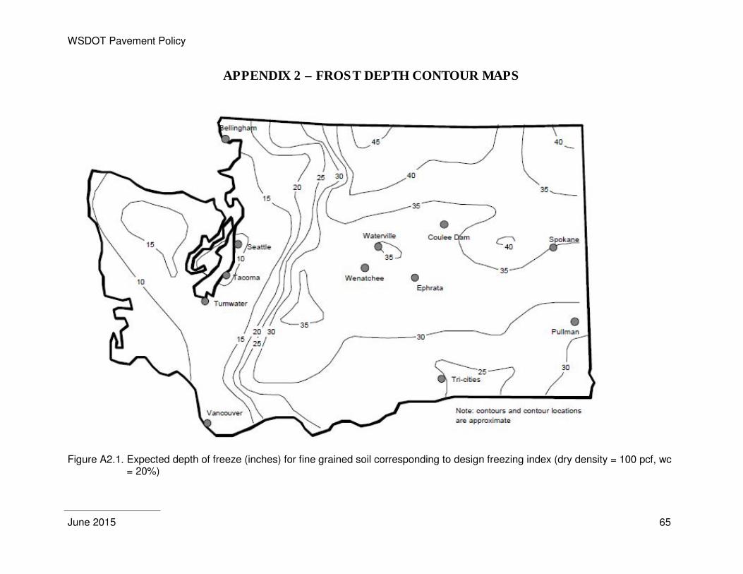
WSDOT Pavement Policy
June 2015 65
APPENDIX 2 – FROST DEPTH CONTOUR MAPS
Figure A2.1. Expected depth of freeze (inches) for fine grained soil corresponding to design freezing index (dry density = 100 pcf, wc
= 20%)
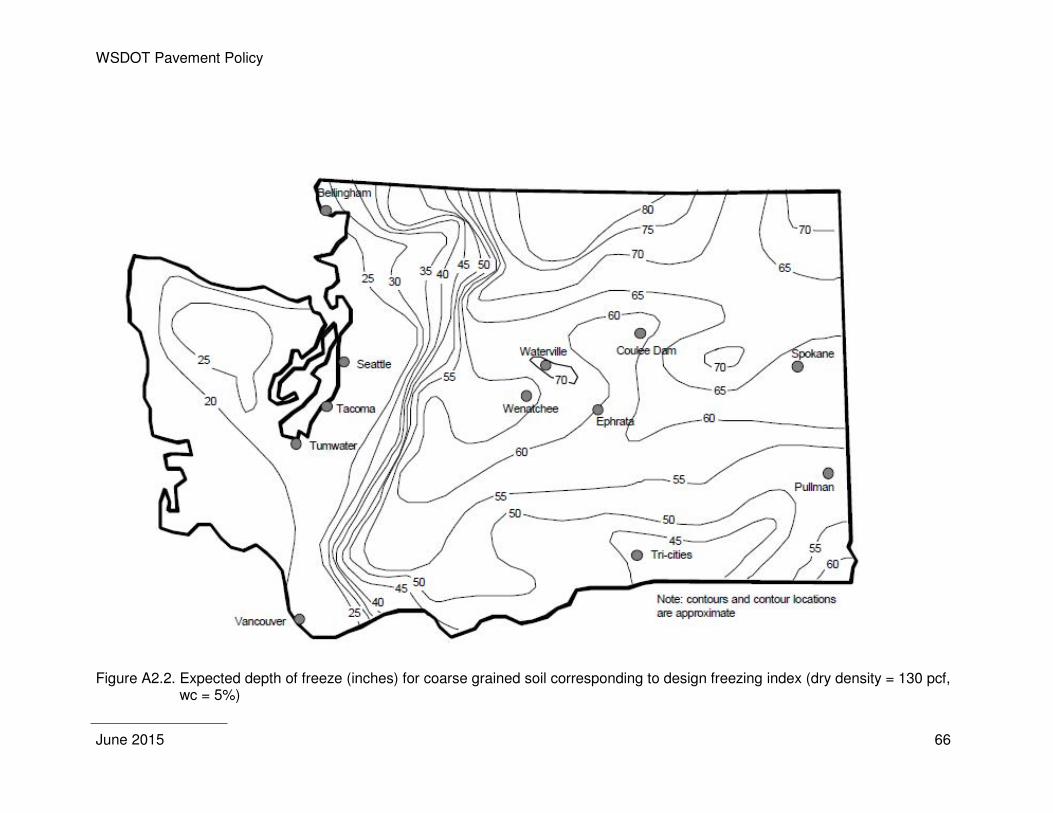
WSDOT Pavement Policy
June 2015 66
Figure A2.2. Expected depth of freeze (inches) for coarse grained soil corresponding to design freezing index (dry density = 130 pcf,
wc = 5%)
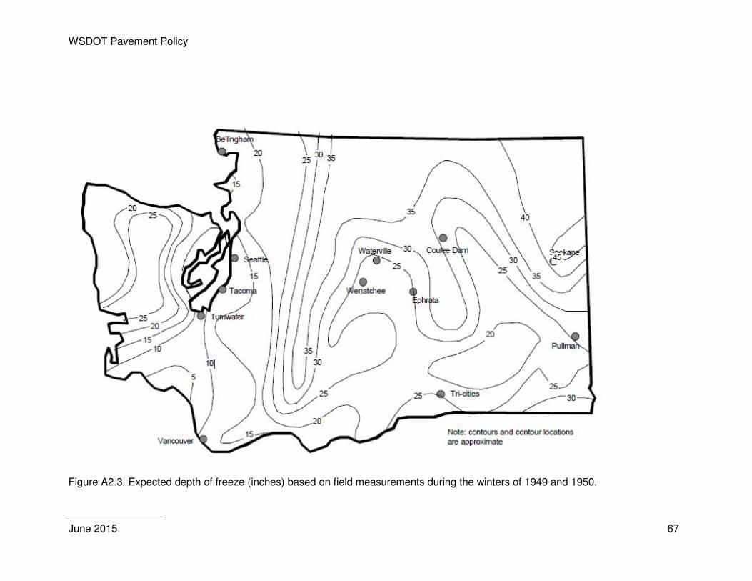
WSDOT Pavement Policy
June 2015 67
Figure A2.3. Expected depth of freeze (inches) based on field measurements during the winters of 1949 and 1950.

WSDOT Pavement Policy
June 2015 68
WSDOT Pavement Policy
June 2015 69
APPENDIX 3 – PAVEMENT TYPE SELECTION CRITERIA
The information presented in Appendix 3 is intended as a guide for determining the pavement type selection for individual projects. Pavement type selection is a three-part process which includes a pavement design analysis, life cycle cost analysis and evaluation of project specific details. Each of the following section provides examples and discussion necessary to prepare the final pavement type selection determination.
Pavement Design Analysis
The pavement design should be performed first, since the results may preclude the need to continue with the remainder of the pavement type selection process (life cycle cost analysis and project specific details).
The pavement design analysis includes the review and analysis of the following: subgrade competency, traffic analysis, materials, climate/drainage, environment, construction considerations, and any other pavement design factors.
1. Subgrade Competency
This is the only “go/no go” decision to be made under the pavement design analysis. HMA tends to perform better in situations where long-term settlement is expected. If the engineering evaluation of the subgrade concludes the presence of peat or organic silts or the potential for long-term settlement that exceeds two or more inches, then the pavement type selection is complete and HMA is the selected pavement type. If the engineering evaluation of the subgrade concludes that either pavement type is viable, then the pavement type selection process proceeds to the next step.
2. Classification for Pavement Design
Pavements can be divided into different traffic classes depending on light to heavy traffic. Flexible and rigid pavements can be designed to accommodate these wide traffic ranges. For each of the pavement classes, traffic is quantified according to the number of ESALs. Based on the traffic volume and traffic growth rate, the design traffic loading can be estimated over the structural design period or the analysis period. The design traffic loading determines the pavement thickness needed to support the traffic loading over the structural design period.
Correctly estimating design traffic is crucial to selecting an appropriate pavement type. To calculate the total design traffic per lane that a pavement will carry over its structural design life, it is necessary to estimate present traffic loading. To estimate future traffic loadings, traffic growth rates should be used. Depending on the roadway segment’s importance, conducting a sensitivity analysis to compare growth rates and the impact of the growth rate on pavement thickness may be worthwhile.
3. Materials
Selecting materials for a road pavement design is determined by the availability of suitable materials, environmental considerations, construction methods, economics, and previous performance. To select the materials that best suit the conditions, these factors must be evaluated during the design to ensure a whole-life cycle strategy.
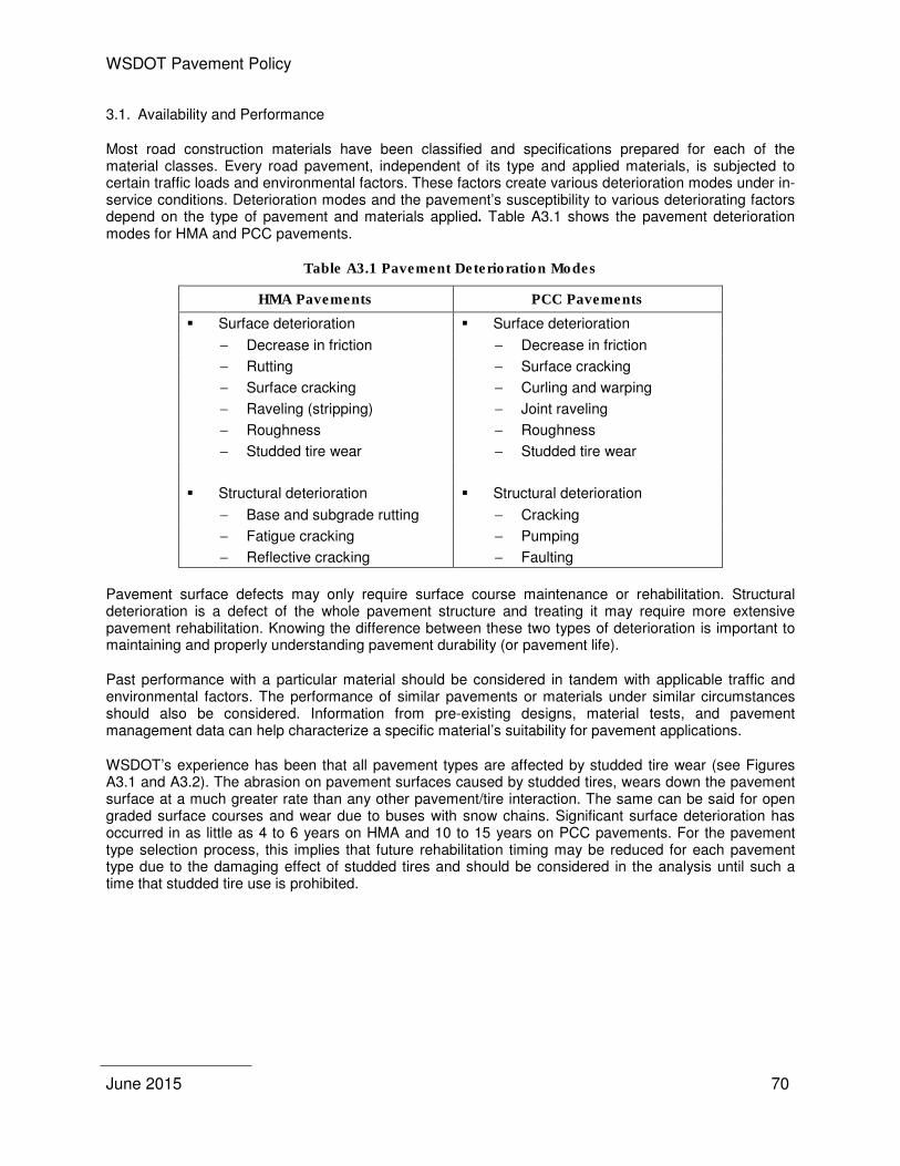
WSDOT Pavement Policy
June 2015 70
3.1. Availability and Performance
Most road construction materials have been classified and specifications prepared for each of the material classes. Every road pavement, independent of its type and applied materials, is subjected to certain traffic loads and environmental factors. These factors create various deterioration modes under in-service conditions. Deterioration modes and the pavement’s susceptibility to various deteriorating factors depend on the type of pavement and materials applied. Table A3.1 shows the pavement deterioration modes for HMA and PCC pavements.
Table A3.1 Pavement Deterioration Modes
HMA Pavements PCC Pavements
� Surface deterioration � Surface deterioration
− Decrease in friction − Decrease in friction
− Rutting − Surface cracking
− Surface cracking − Curling and warping
− Raveling (stripping) − Joint raveling
− Roughness − Roughness
− Studded tire wear − Studded tire wear
� Structural deterioration � Structural deterioration
− Base and subgrade rutting − Cracking
− Fatigue cracking − Pumping
− Reflective cracking − Faulting
Pavement surface defects may only require surface course maintenance or rehabilitation. Structural deterioration is a defect of the whole pavement structure and treating it may require more extensive pavement rehabilitation. Knowing the difference between these two types of deterioration is important to maintaining and properly understanding pavement durability (or pavement life).
Past performance with a particular material should be considered in tandem with applicable traffic and environmental factors. The performance of similar pavements or materials under similar circumstances should also be considered. Information from pre-existing designs, material tests, and pavement management data can help characterize a specific material’s suitability for pavement applications.
WSDOT’s experience has been that all pavement types are affected by studded tire wear (see Figures A3.1 and A3.2). The abrasion on pavement surfaces caused by studded tires, wears down the pavement surface at a much greater rate than any other pavement/tire interaction. The same can be said for open graded surface courses and wear due to buses with snow chains. Significant surface deterioration has occurred in as little as 4 to 6 years on HMA and 10 to 15 years on PCC pavements. For the pavement type selection process, this implies that future rehabilitation timing may be reduced for each pavement type due to the damaging effect of studded tires and should be considered in the analysis until such a time that studded tire use is prohibited.
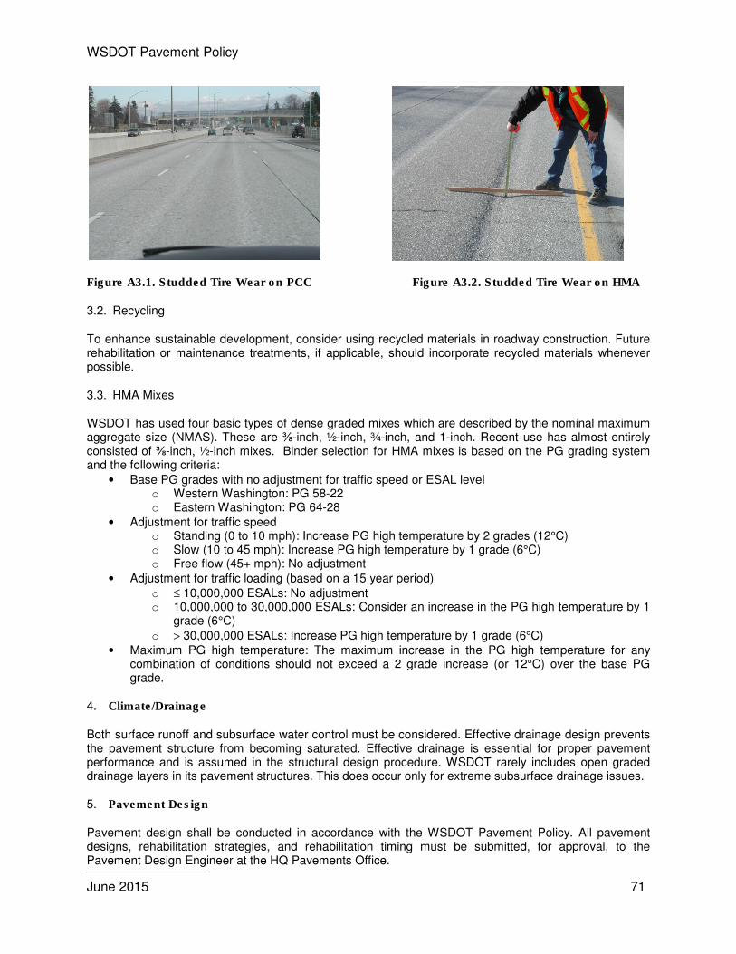
WSDOT Pavement Policy
June 2015 71
Figure A3.1. Studded Tire Wear on PCC Figure A3.2. Studded Tire Wear on HMA
3.2. Recycling
To enhance sustainable development, consider using recycled materials in roadway construction. Future rehabilitation or maintenance treatments, if applicable, should incorporate recycled materials whenever possible.
3.3. HMA Mixes
WSDOT has used four basic types of dense graded mixes which are described by the nominal maximum aggregate size (NMAS). These are ⅜-inch, ½-inch, ¾-inch, and 1-inch. Recent use has almost entirely consisted of ⅜-inch, ½-inch mixes. Binder selection for HMA mixes is based on the PG grading system and the following criteria:
• Base PG grades with no adjustment for traffic speed or ESAL level o Western Washington: PG 58-22 o Eastern Washington: PG 64-28
• Adjustment for traffic speed o Standing (0 to 10 mph): Increase PG high temperature by 2 grades (12°C) o Slow (10 to 45 mph): Increase PG high temperature by 1 grade (6°C) o Free flow (45+ mph): No adjustment
• Adjustment for traffic loading (based on a 15 year period) o ≤ 10,000,000 ESALs: No adjustment o 10,000,000 to 30,000,000 ESALs: Consider an increase in the PG high temperature by 1
grade (6°C)
o > 30,000,000 ESALs: Increase PG high temperature by 1 grade (6°C) • Maximum PG high temperature: The maximum increase in the PG high temperature for any
combination of conditions should not exceed a 2 grade increase (or 12°C) over the base PG grade.
4. Climate/Drainage
Both surface runoff and subsurface water control must be considered. Effective drainage design prevents the pavement structure from becoming saturated. Effective drainage is essential for proper pavement performance and is assumed in the structural design procedure. WSDOT rarely includes open graded drainage layers in its pavement structures. This does occur only for extreme subsurface drainage issues.
5. Pavement Design
Pavement design shall be conducted in accordance with the WSDOT Pavement Policy. All pavement designs, rehabilitation strategies, and rehabilitation timing must be submitted, for approval, to the Pavement Design Engineer at the HQ Pavements Office.

WSDOT Pavement Policy
June 2015 72
5.1. Additional PCC Issues
WSDOT has demonstrated that the PCC pavements constructed in the late 1950s through the 1960s are able to obtain a 50-year or more pavement life as long as joint faulting can be overcome. The ability to provide adequate joint design to minimize joint faulting is addressed by requiring the use of non-erodible bases and dowel bars (1-½ inch diameter by 18 inch length) at every transverse joint. The use of epoxy-coated dowel bars, both locally and nationally, does not necessarily ensure that a 50-year performance life will be obtained. Dowel bar specifications require the use of corrosion resistant dowel bars (stainless steel alternatives, low-carbon chromium steel (ASTM A1035) or Zinc clad) on all newly constructed concrete pavements (Appendix 1). Rehabilitation of PCC pavements will potentially require diamond grinding following 20 to 30 years of traffic to address studded tire wear.
5.2. Additional HMA Issues
For heavily trafficked roadways (primarily the interstate and principal arterials), the pavement thickness should be designed to such a depth that future roadway reconstruction is not necessary. The pavement thickness should be designed for 50 years so that traffic will not generate significant bottom up (fatigue) cracking. Future mill and fill or HMA overlays will be required to address surface distress (rutting or top down cracking) and aging of the HMA surface.
5.3. Effect of Studded Tire Wear.
In the past, WSDOT has increased the PCC slab thickness by one inch to accommodate future diamond grinding(s). The current PCC slab thicknesses contained in Table 5.1 includes an additional inch for grinding and adding an additional inch when using the design table is no longer necessary. Studded tire damage is also a concern for HMA pavements. WSDOT has constructed a number of stone matrix asphalt (SMA) pavements, but have had a number of construction related difficulties, such that the ability to determine the impact that a SMA will have on reducing studded tire damage is unknown. In the life cycle cost analysis, the accelerated wear on HMA pavements will be incorporated through a shorter performance period on future overlays (but only as supported by Pavement Management data).
6. Construction Considerations
Pavement construction issues are an important component of the selection of pavement type. These issues can include:
� Pavement thickness constraints. Consider the impact of utilities below the pavement and overhead clearances may have on limiting the layer thickness and type, and/or limit future overlay thickness.
� Effects on detours, bypasses, and alternate routes. Consider the geometric and structural capacity of detours, bypasses and alternate routes to accommodate rerouted traffic.
� Effects of underground pipes and services on performance. Determine the impact of existing utilities and future utility upgrades on initial and future rehabilitation treatments.
� Anticipated future improvements and upgrades. Consider if the pavement type restricts or minimizes the ability to efficiently and cost effectively upgrade and/or improve the roadway width, geometry, structural support, etc.
� Impact on maintenance operations, including winter maintenance. Will the selected pavement type have impacts due to freeze-thaw (surface and full-depth) or snow and ice removal?
� Grades, curvature, and unique loadings (slow-moving vehicles and starting and stopping). How will steep grades, curvature and unique loadings impact pavement performance? Slow moving vehicles will generate increased strain levels in the HMA pavement structure and these strains can significantly impact pavement performance (i.e. rutting and cracking).
� A schedule analysis may need to be conducted to determine critical construction features (haul truck access, traffic control constraints – road closures, etc.) and their impact on the project. This should also include staging analysis for multiple projects within the project corridor (to ensure that alternate routes are free of traffic delay due to construction activities). The Construction
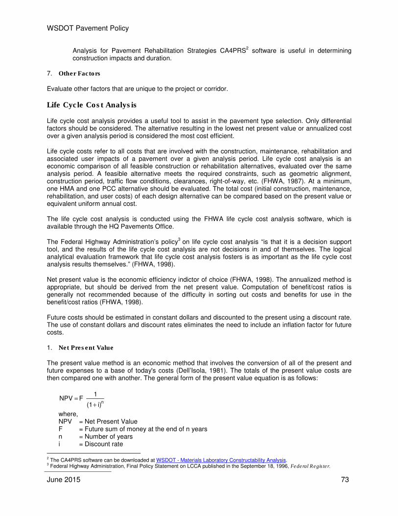
WSDOT Pavement Policy
June 2015 73
Analysis for Pavement Rehabilitation Strategies CA4PRS2 software is useful in determining
construction impacts and duration.
7. Other Factors
Evaluate other factors that are unique to the project or corridor.
Life Cycle Cost Analysis
Life cycle cost analysis provides a useful tool to assist in the pavement type selection. Only differential factors should be considered. The alternative resulting in the lowest net present value or annualized cost over a given analysis period is considered the most cost efficient.
Life cycle costs refer to all costs that are involved with the construction, maintenance, rehabilitation and associated user impacts of a pavement over a given analysis period. Life cycle cost analysis is an economic comparison of all feasible construction or rehabilitation alternatives, evaluated over the same analysis period. A feasible alternative meets the required constraints, such as geometric alignment, construction period, traffic flow conditions, clearances, right-of-way, etc. (FHWA, 1987). At a minimum, one HMA and one PCC alternative should be evaluated. The total cost (initial construction, maintenance, rehabilitation, and user costs) of each design alternative can be compared based on the present value or equivalent uniform annual cost.
The life cycle cost analysis is conducted using the FHWA life cycle cost analysis software, which is available through the HQ Pavements Office.
The Federal Highway Administration’s policy3
on life cycle cost analysis “is that it is a decision support tool, and the results of the life cycle cost analysis are not decisions in and of themselves. The logical analytical evaluation framework that life cycle cost analysis fosters is as important as the life cycle cost analysis results themselves.” (FHWA, 1998).
Net present value is the economic efficiency indictor of choice (FHWA, 1998). The annualized method is appropriate, but should be derived from the net present value. Computation of benefit/cost ratios is generally not recommended because of the difficulty in sorting out costs and benefits for use in the benefit/cost ratios (FHWA, 1998).
Future costs should be estimated in constant dollars and discounted to the present using a discount rate. The use of constant dollars and discount rates eliminates the need to include an inflation factor for future costs.
1. Net Present Value
The present value method is an economic method that involves the conversion of all of the present and future expenses to a base of today's costs (Dell’Isola, 1981). The totals of the present value costs are then compared one with another. The general form of the present value equation is as follows:
where, NPV = Net Present Value F = Future sum of money at the end of n years n = Number of years i = Discount rate
2 The CA4PRS software can be downloaded at WSDOT - Materials Laboratory Constructability Analysis. 3 Federal Highway Administration, Final Policy Statement on LCCA published in the September 18, 1996, Federal Register.
i) (1
1 F NPV
n+
=
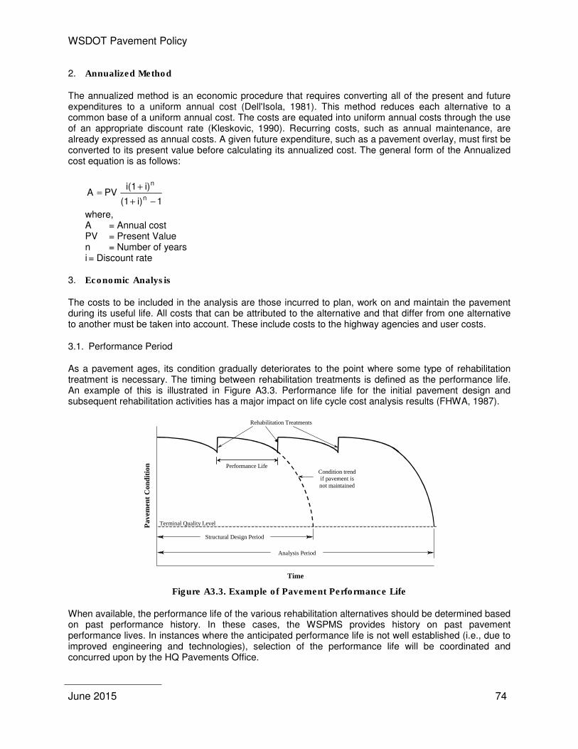
WSDOT Pavement Policy
June 2015 74
2. Annualized Method
The annualized method is an economic procedure that requires converting all of the present and future expenditures to a uniform annual cost (Dell'Isola, 1981). This method reduces each alternative to a common base of a uniform annual cost. The costs are equated into uniform annual costs through the use of an appropriate discount rate (Kleskovic, 1990). Recurring costs, such as annual maintenance, are already expressed as annual costs. A given future expenditure, such as a pavement overlay, must first be converted to its present value before calculating its annualized cost. The general form of the Annualized cost equation is as follows:
1i)(1
i)i(1PV A
n
n
−+
+=
where, A = Annual cost PV = Present Value n = Number of years i = Discount rate
3. Economic Analysis
The costs to be included in the analysis are those incurred to plan, work on and maintain the pavement during its useful life. All costs that can be attributed to the alternative and that differ from one alternative to another must be taken into account. These include costs to the highway agencies and user costs.
3.1. Performance Period
As a pavement ages, its condition gradually deteriorates to the point where some type of rehabilitation treatment is necessary. The timing between rehabilitation treatments is defined as the performance life. An example of this is illustrated in Figure A3.3. Performance life for the initial pavement design and subsequent rehabilitation activities has a major impact on life cycle cost analysis results (FHWA, 1987).
Figure A3.3. Example of Pavement Performance Life
When available, the performance life of the various rehabilitation alternatives should be determined based on past performance history. In these cases, the WSPMS provides history on past pavement performance lives. In instances where the anticipated performance life is not well established (i.e., due to improved engineering and technologies), selection of the performance life will be coordinated and concurred upon by the HQ Pavements Office.
Pa
vem
ent
Co
nd
itio
n
Time
Analysis Period
Terminal Quality Level
Structural Design Period
Rehabilitation Treatments
Condition trend if pavement is not maintained
Performance Life
WSDOT Pavement Policy
June 2015 75
3.2. Initial Construction Costs
Unit costs vary according to location, the availability of materials, the scope of the project and any applicable standards. They can be estimated based on previous experiences, generally by averaging the bids submitted for recent projects of similar scope. Typical item costs can be located in bid item tabulations. The bid item costs may need to be adjusted according to local availability and work constraints. Mobilization, engineering and contingencies, and preliminary engineering can be excluded (sales tax should be included) for the initial construction cost estimate, since these costs are similar for HMA and PCC.
3.3. Maintenance and Rehabilitation Costs
The type and frequency of future maintenance and rehabilitation operations vary according to the pavement type being considered. Knowing how a particular pavement type performed in the past is a valuable guide in predicting future performance (Penn DOT, 2001). The WSPMS should be reviewed for past performance of rehabilitation and maintenance schedules. Costs must always be determined as realistically and accurately as possible based on local context and specific project features.
When calculating the rehabilitation costs, include the cost of pavement resurfacing or PCC rehabilitation, planning or diamond grinding, shoulders, pavement repair, drainage and guardrail adjustments, maintenance and protection of traffic, etc. Mobilization, engineering, contingencies, preliminary engineering, and sales tax should be included in all rehabilitation costs if they were included in the initial construction cost.
Construction duration should reflect the actual construction time that is required for each pavement type. Construction durations should consider improvements, proposals or innovative contracting procedures in construction processes.
If a difference exists in routine maintenance costs between the various alternatives, these costs should be included in the life cycle cost analysis.
Table A3.2 contains a probable scenario corresponding to average traffic and climate conditions, assuming that state-of-the-art practices have been followed during construction and that maintenance and rehabilitation projects are carried out efficiently and on schedule.
Table A3.2. Rehabilitation Scenario for HMA and PCC Pavements
Year HMA Pavement PCC Pavement
0 Construction or reconstruction Construction or reconstruction
15 0.15’ mill and HMA overlay
20 Diamond grinding
30 0.15’ HMA overlay
40 Diamond grinding
45 0.15’ mill and HMA overlay
50 Salvage value (if applicable) Salvage value (if applicable)
3.4. Salvage Value
Salvage value is the asset value at the end of the analysis period. The difference between the salvage values of the various alternatives for a project can be small, because discounting can considerably reduce this value, but the size of this reduction is influenced by the actual discount rate chosen. As for the value assigned to the pavement materials, or terminal value, predicting the proportion of recovery or recycling of these materials on-site at the end of the analysis period is uncertain.
WSDOT Pavement Policy
June 2015 76
If an alternative has reached its full life cycle at the end of the analysis period, it is generally considered to have no remaining salvage value. If it has not completed a life cycle, it is given a salvage value, which is usually determined by multiplying the last construction or rehabilitation cost, by the ratio of the remaining expected life cycle to the total expected life.
TEL
ERL x CC ValueSalvage =
where, CC = Last construction or rehabilitation project costs ERL = Expected remaining life of the last construction or rehabilitation project TEL = Total expected life of the last construction or rehabilitation project
3.5. User Costs
It is difficult to determine whether or not one rehabilitation alternative results in a higher vehicle operating cost than another. Therefore, the user costs associated with each of the rehabilitation alternatives shall be determined using only costs associated with user delay. This shall be based on the construction periods and the traffic volumes that are affected by each of the rehabilitation alternatives.
Several studies have been performed that associate cost with the amount of time the user is delayed through a construction project. The method used is not as important as using the same method for each of the alternatives.
The costs associated with user delays are estimated only if the effects on traffic differ among the alternatives being analyzed. For future rehabilitation work, user costs associated with delays can be substantial for heavily travelled roadways, especially when work is frequent.
While there are several different sources for the dollar value of time delay, the recommended mean values and ranges for the value of time (in 2006 dollars) shown in Table A3.3, are reasonable.
Table A3.3. Recommended Dollar Values per Vehicle Hour of Delay (FHWA, 1998) (adjusted to 2015 dollars)
4
Vehicle Class Value Per Vehicle Hour
Value Range
Passenger Vehicles $17.34 $15 to $20
Single-Unit Trucks $27.90 $26 to $30
Combination Trucks $33.93 $32 to $36
3.6. Other Costs
Surfacing types and characteristics influence the noise emitted on tire-to-pavement contact. If construction of a noise attenuation structure is planned, the cost of that structure must be included in the treatment costs of the alternative being analyzed. The issue of safety can be addressed similarly.
3.7. Discount Rate
"In a life cycle cost analysis, a discount rate is needed to compare costs occurring at different points in time. The discount rate reduces the impact of future costs on the analysis, reflecting the fact that money has a time value" (Peterson, 1985). The discount rate is defined as the difference between the market interest rate and inflation, using constant dollars.
4 Calculator for converting costs to current dollars can be accessed at http://data.bls.gov/cgi-bin/cpicalc.pl
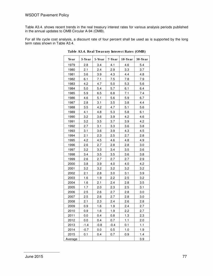
WSDOT Pavement Policy
June 2015 77
Table A3.4. shows recent trends in the real treasury interest rates for various analysis periods published in the annual updates to OMB Circular A-94 (OMB).
For all life cycle cost analysis, a discount rate of four percent shall be used as is supported by the long term rates shown in Table A3.4.
Table A3.4. Real Treasury Interest Rates (OMB)
Year 3-Year 5-Year 7-Year 10-Year 30-Year
1979 2.8 3.4 4.1 4.6 5.4
1980 2.1 2.4 2.9 3.3 3.7
1981 3.6 3.9 4.3 4.4 4.8
1982 6.1 7.1 7.5 7.8 7.9
1983 4.2 4.7 5.0 5.3 5.6
1984 5.0 5.4 5.7 6.1 6.4
1985 5.9 6.5 6.8 7.1 7.4
1986 4.6 5.1 5.6 5.9 6.7
1987 2.8 3.1 3.5 3.8 4.4
1988 3.5 4.2 4.7 5.1 5.6
1989 4.1 4.8 5.3 5.8 6.1
1990 3.2 3.6 3.9 4.2 4.6
1991 3.2 3.5 3.7 3.9 4.2
1992 2.7 3.1 3.3 3.6 3.8
1993 3.1 3.6 3.9 4.3 4.5
1994 2.1 2.3 2.5 2.7 2.8
1995 4.2 4.5 4.6 4.8 4.9
1996 2.6 2.7 2.8 2.8 3.0
1997 3.2 3.3 3.4 3.5 3.6
1998 3.4 3.5 3.5 3.6 3.8
1999 2.6 2.7 2.7 2.7 2.9
2000 3.8 3.9 4.0 4.0 4.2
2001 3.2 3.2 3.2 3.2 3.2
2002 2.1 2.8 3.0 3.1 3.9
2003 1.6 1.9 2.2 2.5 3.2
2004 1.6 2.1 2.4 2.8 3.5
2005 1.7 2.0 2.3 2.5 3.1
2006 2.5 2.6 2.7 2.8 3.0
2007 2.5 2.6 2.7 2.8 3.0
2008 2.1 2.3 2.4 2.6 2.8
2009 0.9 1.6 1.9 2.4 2.7
2010 0.9 1.6 1.9 2.2 2.7
2011 0.0 0.4 0.8 1.3 2.3
2012 0.0 0.4 0.7 1.1 2.0
2013 -1.4 -0.8 -0.4 0.1 1.1
2014 -0.7 0.0 0.5 1.0 1.9
2015 0.1 0.4 0.7 0.9 1.4
Average 3.9
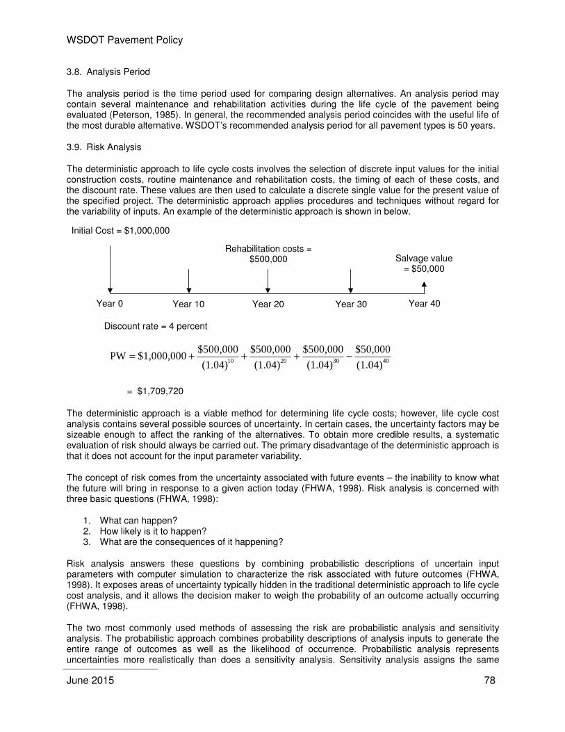
WSDOT Pavement Policy
June 2015 78
3.8. Analysis Period
The analysis period is the time period used for comparing design alternatives. An analysis period may contain several maintenance and rehabilitation activities during the life cycle of the pavement being evaluated (Peterson, 1985). In general, the recommended analysis period coincides with the useful life of the most durable alternative. WSDOT’s recommended analysis period for all pavement types is 50 years.
3.9. Risk Analysis
The deterministic approach to life cycle costs involves the selection of discrete input values for the initial construction costs, routine maintenance and rehabilitation costs, the timing of each of these costs, and the discount rate. These values are then used to calculate a discrete single value for the present value of the specified project. The deterministic approach applies procedures and techniques without regard for the variability of inputs. An example of the deterministic approach is shown in below.
Initial Cost = $1,000,000
Year 0 Year 10 Year 20 Year 30 Year 40
Rehabilitation costs = $500,000 Salvage value
= $50,000
Discount rate = 4 percent
(1.04)
$50,000
(1.04)
$500,000
(1.04)
$500,000
(1.04)
$500,000$1,000,000PW
40302010−+++=
= $1,709,720
The deterministic approach is a viable method for determining life cycle costs; however, life cycle cost analysis contains several possible sources of uncertainty. In certain cases, the uncertainty factors may be sizeable enough to affect the ranking of the alternatives. To obtain more credible results, a systematic evaluation of risk should always be carried out. The primary disadvantage of the deterministic approach is that it does not account for the input parameter variability.
The concept of risk comes from the uncertainty associated with future events – the inability to know what the future will bring in response to a given action today (FHWA, 1998). Risk analysis is concerned with three basic questions (FHWA, 1998):
1. What can happen? 2. How likely is it to happen? 3. What are the consequences of it happening?
Risk analysis answers these questions by combining probabilistic descriptions of uncertain input parameters with computer simulation to characterize the risk associated with future outcomes (FHWA, 1998). It exposes areas of uncertainty typically hidden in the traditional deterministic approach to life cycle cost analysis, and it allows the decision maker to weigh the probability of an outcome actually occurring (FHWA, 1998).
The two most commonly used methods of assessing the risk are probabilistic analysis and sensitivity analysis. The probabilistic approach combines probability descriptions of analysis inputs to generate the entire range of outcomes as well as the likelihood of occurrence. Probabilistic analysis represents uncertainties more realistically than does a sensitivity analysis. Sensitivity analysis assigns the same

WSDOT Pavement Policy
June 2015 79
weighting to all extreme or mean values, whereas probabilistic analysis assigns the lowest probability to extreme values. A probabilistic analysis is advocated, but if this is not possible, a sensitivity analysis at the very least should be carried out.
3.10. Probabilistic Analysis
The probabilistic approach takes into account the uncertainty of the variables used as inputs in the life cycle cost analysis. The probability distribution is selected for each input variable, which are then used to generate the entire range of outcomes and the likelihood of occurrences for both the associated costs and the performance life. The procedure often used to apply a probability distribution is a “Monte Carlo Simulation”. The Monte Carlo Simulation is a computerized procedure that takes each input variable, assigns a range of values (using the mean and standard deviation of the input variable), and runs multiple combinations of all inputs and ranges to generate a life cycle cost probability distribution. Using the probabilistic approach allows for the ability of determining the variability or “spread” of the life cycle cost distributions and determining which alternative has the lower associated risk (see Figure A3.4).
WSDOT input values for the probabilistic analysis are contained in Appendix 5. An example of a probabilistic analysis is included in Appendix 6.
By performing the Monte Carlo computer simulation, thousands, even tens of thousands of samples are randomly drawn from each input distribution to calculate a separate what-if scenario (FHWA, 1998). Risk analysis results are presented in the form of a probability distribution that describes the range of possible outcomes along with a probability weighting of occurrence (FHWA, 1998). With this information, the decision maker knows not only the full range of possible values, but also the relative probability of any particular outcome actually occurring (FHWA, 1998).
Pro
ba
bil
ity
Life-Cycle Cost
Alternative A
Alternative B
The narrower the distribution - the less associated risk
Figure A3.4. Probability Distribution
3.11. Sensitivity Analysis
Sensitivity analysis is a technique used to determine the influence of major input assumptions, projections, and estimates on life cycle cost analysis results. In a sensitivity analysis, major input values are varied (either within some percentage of the initial value or over a range of values) while all other input values remain constant and the amount of change in results is noted (FHWA, 1998).
An example of a sensitivity analysis is shown below.
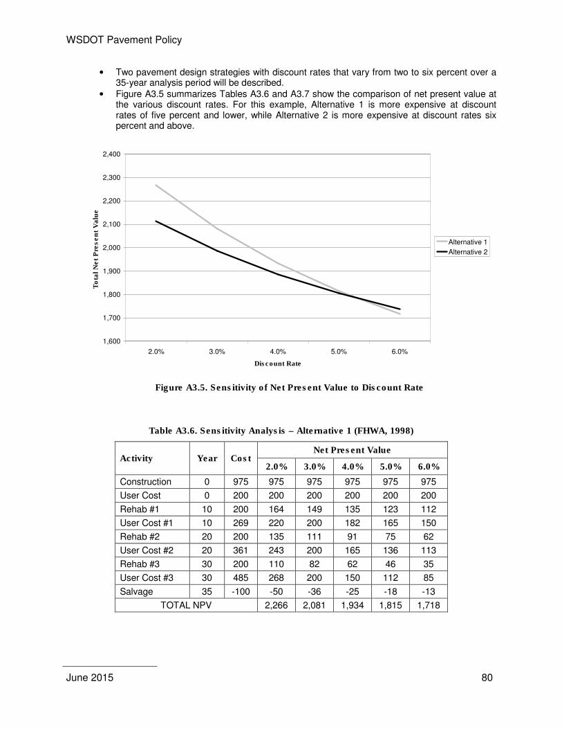
WSDOT Pavement Policy
June 2015 80
• Two pavement design strategies with discount rates that vary from two to six percent over a 35-year analysis period will be described.
• Figure A3.5 summarizes Tables A3.6 and A3.7 show the comparison of net present value at the various discount rates. For this example, Alternative 1 is more expensive at discount rates of five percent and lower, while Alternative 2 is more expensive at discount rates six percent and above.
Figure A3.5. Sensitivity of Net Present Value to Discount Rate
Table A3.6. Sensitivity Analysis – Alternative 1 (FHWA, 1998)
Activity Year Cost Net Present Value
2.0% 3.0% 4.0% 5.0% 6.0%
Construction 0 975 975 975 975 975 975
User Cost 0 200 200 200 200 200 200
Rehab #1 10 200 164 149 135 123 112
User Cost #1 10 269 220 200 182 165 150
Rehab #2 20 200 135 111 91 75 62
User Cost #2 20 361 243 200 165 136 113
Rehab #3 30 200 110 82 62 46 35
User Cost #3 30 485 268 200 150 112 85
Salvage 35 -100 -50 -36 -25 -18 -13
TOTAL NPV 2,266 2,081 1,934 1,815 1,718
1,600
1,700
1,800
1,900
2,000
2,100
2,200
2,300
2,400
2.0% 3.0% 4.0% 5.0% 6.0%
Discount Rate
To
tal
Ne
t P
res
en
t V
alu
e
Alternative 1
Alternative 2
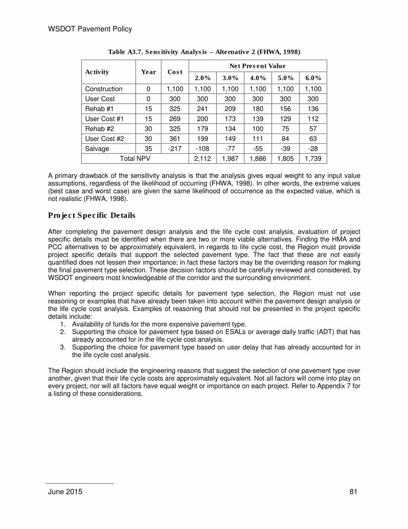
WSDOT Pavement Policy
June 2015 81
Table A3.7. Sensitivity Analysis – Alternative 2 (FHWA, 1998)
Activity Year Cost Net Present Value
2.0% 3.0% 4.0% 5.0% 6.0%
Construction 0 1,100 1,100 1,100 1,100 1,100 1,100
User Cost 0 300 300 300 300 300 300
Rehab #1 15 325 241 209 180 156 136
User Cost #1 15 269 200 173 139 129 112
Rehab #2 30 325 179 134 100 75 57
User Cost #2 30 361 199 149 111 84 63
Salvage 35 -217 -108 -77 -55 -39 -28
Total NPV 2,112 1,987 1,886 1,805 1,739
A primary drawback of the sensitivity analysis is that the analysis gives equal weight to any input value assumptions, regardless of the likelihood of occurring (FHWA, 1998). In other words, the extreme values (best case and worst case) are given the same likelihood of occurrence as the expected value, which is not realistic (FHWA, 1998).
Project Specific Details
After completing the pavement design analysis and the life cycle cost analysis, evaluation of project specific details must be identified when there are two or more viable alternatives. Finding the HMA and PCC alternatives to be approximately equivalent, in regards to life cycle cost, the Region must provide project specific details that support the selected pavement type. The fact that these are not easily quantified does not lessen their importance; in fact these factors may be the overriding reason for making the final pavement type selection. These decision factors should be carefully reviewed and considered, by WSDOT engineers most knowledgeable of the corridor and the surrounding environment.
When reporting the project specific details for pavement type selection, the Region must not use reasoning or examples that have already been taken into account within the pavement design analysis or the life cycle cost analysis. Examples of reasoning that should not be presented in the project specific details include:
1. Availability of funds for the more expensive pavement type. 2. Supporting the choice for pavement type based on ESALs or average daily traffic (ADT) that has
already accounted for in the life cycle cost analysis. 3. Supporting the choice for pavement type based on user delay that has already accounted for in
the life cycle cost analysis.
The Region should include the engineering reasons that suggest the selection of one pavement type over another, given that their life cycle costs are approximately equivalent. Not all factors will come into play on every project, nor will all factors have equal weight or importance on each project. Refer to Appendix 7 for a listing of these considerations.
WSDOT Pavement Policy
June 2015 82
References
Dell'Isola, A. J. and S. J. Kirk (1981). Life Cycle Costing for Design Professionals, McGraw-Hill, New York.
Federal Highway Administration (FHWA), (1987). Techniques for Pavement Rehabilitation, Participant's Notebook, FHWA-HI-90-022.
Federal Highway Administration (FHWA), (1998). Life cycle Cost Analysis in Pavement Design, FHWA-SA-98-079 (1998).
Kleskovic, Peter Z. (1990). A Discussion of Discount Rates for Economic Analysis of Pavement”, Draft Report, FHWA Pavement Division.
Office of Management and Budget (OMB) (1992—updated 2015), Guidelines and Discount Rates for Benefit-Cost Analysis of Federal Programs, Circular No. A-94 (Revised). http://www.whitehouse.gov/omb/circulars/a094/a094.html#ap-b
Pennsylvania Department of Transportation (Penn DOT), (2001). Publication 242 – Pavement Policy Manual. ftp://ftp.dot.state.pa.us/public/Bureaus/BOMO/RM /Publication242.pdf.
Peterson, Dale E. (1985). NCHRP Synthesis of Highway Practice No. 122: Life cycle Cost Analysis of Pavements, Highway Research Board, National Research Council, Washington, D.C.
WSDOT Pavement Policy
June 2015 83
APPENDIX 4 – EXAMPLE PAVEMENT TYPE SELECTION REPORT
June 8, 2009 TO: L. Laird Chief Engineer
Assistant Secretary Engineering and Regional Operations FROM: Jeff Uhlmeyer (360) 709-5485 SUBJECT: SR 704, MP 0.00 to MP 6.00 VIC Cross Base Highway
Pavement Type Selection Protocol Analysis
Attached for your signature is the Pavement Type Selection Committee approval form for SR 704, Cross Base Highway. Please return the completed approval to the State Materials Lab. This approval is according to the procedure for activating the Pavement Type Selection Committee. The procedure is described in the attached June 29, 2004 letter (copy included for each committee member) approved by L. Laird. If you need clarification or have comments please call Jeff Uhlmeyer at 709-5485. JU:ctk JU cc: Jay Alexander, Director Capital Program Development & Management, 47325 Pasco Bakotich, State Design Engineer, 47329 Chris Christopher, State Construction Engineer, 47354 Kevin Dayton, Olympic Region Administrator, 47440
WSDOT Pavement Policy
June 2015 84
June 8, 2009 TO: L. Laird, 47315 Chief Engineer
Assistant Secretary of Engineering and Regional Operations FROM: Chris Christopher, 47354 State Construction Engineer SUBJECT: Pavement Type Selection When the pavement type selection has been completed and forwarded to the State Materials Laboratory, the Pavement Division will formulate the Pavement Type Selection Committee (referred to as the Committee) Approval Letter and request that each member of the Committee sign and forward the letter on to the next member. The Committee is not required to convene if the life cycle cost analysis between the alternatives is greater than 15 percent and the recommendations are acceptable to both the Region and the State Materials Laboratory. The Approval Letter shall provide the necessary documentation that supports the Committee’s selection of the pavement type.
Projects to be reviewed shall be distributed to the Committee members for approval (see attached example of Approval Letter). Based on this review and obtaining consensus from the Committee, the Pavement Division will either process the Approval Letter, take appropriate action to obtain consensus, or convene the Committee.
In order to expedite the required time and expended level of effort for the review of pavement type selection projects, the following procedure is recommended:
1. The Committee should convene if the pavement type recommended by the Region is contrary to pavement design and engineering analysis recommendations. The pavement design and engineering analysis recommendations shall be subject to the review of the Pavement Division or any member of the Committee. Under these circumstances it shall be the responsibility of the Pavements Division or the Committee member to formulate, in writing, why the selected pavement type is not appropriate and distribute his/her rationale to all members. If all members agree with the recommendations a meeting will not be necessary, otherwise, the Committee should convene.
2. The Committee should convene at the request of any member.
TEB: jsu

WSDOT Pavement Policy
June 2015 85
PAVEMENT TYPE SELECTION
SR 704
Cross Base Highway
MP 0.00 to MP 6.00 Vicinity
The Pavement Type Selection Committee has completed its review of the pavement type selection for project SR 704 Cross Base Highway located in central Pierce County.
This project consists of constructing a new six-mile long East-West divided highway connecting Interstate 5 at Thorne Lane and State Route 7 at 176th Street. The proposed roadway section will consist of two Eastbound and two Westbound 12-ft. lanes with 4-ft. inside and 10-ft. outside shoulders. The design allows for the addition of future HOV lanes in the median.
Following the procedure in the Pavement Type Selection Protocol, the analysis indicates the following:
I. Pavement Design Analysis. There are no pavement design issues. Both Hot Mix Asphalt (HMA) and Portland Cement Concrete (PCC) are viable alternatives.
II. Life Cycle Cost Analysis. The HMA cost is 50-53% less than PCC. HMA is the selected option.
III. Engineering Analysis. Not performed. The Life Cycle Cost difference is greater than 15% between the two pavement types.
The Committee based on this analysis approves the use of HMA on this project.
The Pavement Type Selection Committee
______________________________ __________________________________ Chief Engineer State Design Engineer Assistant Secretary of Engineering and Regional Operations
______________________________ __________________________________ State Construction Engineer Director Capital Program Development and Management
______________________________ Olympic Region Administrator
JU:ck
WSDOT Pavement Policy
June 2015 86
SR 704 - Cross Base Highway
Pavement Type Selection Protocol Analysis
October 28, 2005
Prepared by:
Mel Hitzke, PE - Olympic Region Materials Lab Terry MacAuley, Olympic Region Materials Lab
Reviewed by:
Jeff Uhlmeyer, PE – State Materials Lab – Pavements Division Chuck Kinne, PE – State Materials Lab – Pavements Division
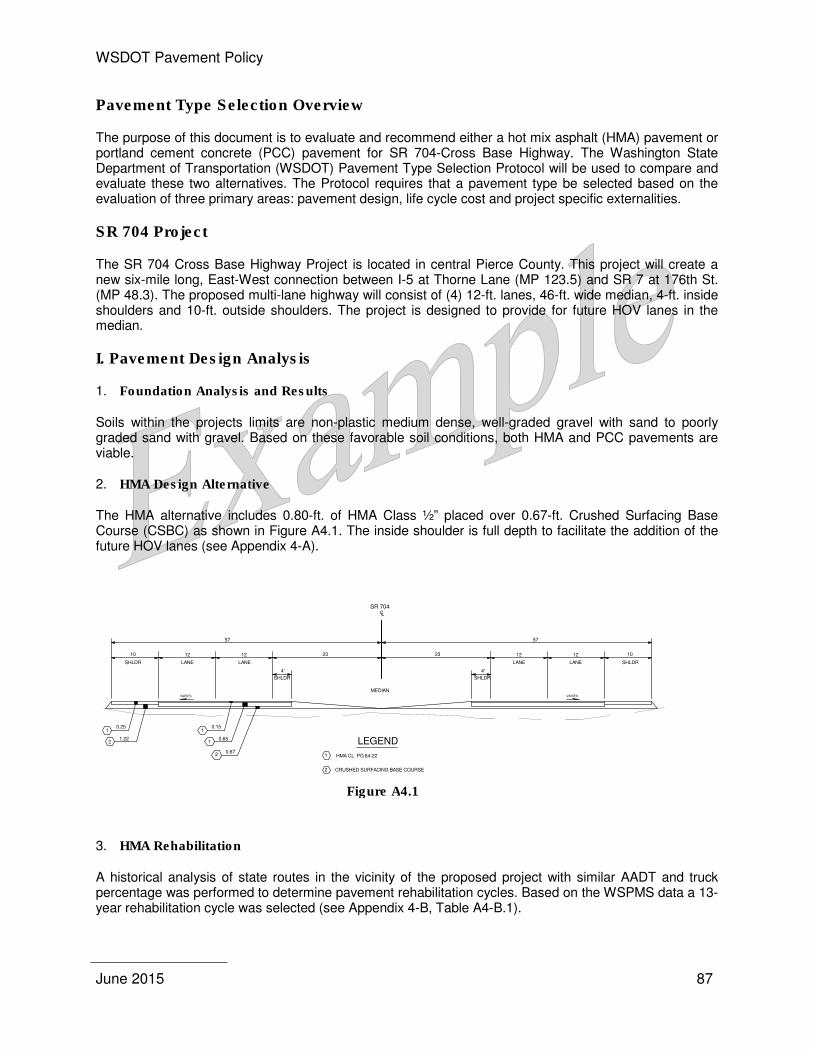
WSDOT Pavement Policy
June 2015 87
Pavement Type Selection Overview
The purpose of this document is to evaluate and recommend either a hot mix asphalt (HMA) pavement or portland cement concrete (PCC) pavement for SR 704-Cross Base Highway. The Washington State Department of Transportation (WSDOT) Pavement Type Selection Protocol will be used to compare and evaluate these two alternatives. The Protocol requires that a pavement type be selected based on the evaluation of three primary areas: pavement design, life cycle cost and project specific externalities.
SR 704 Project
The SR 704 Cross Base Highway Project is located in central Pierce County. This project will create a new six-mile long, East-West connection between I-5 at Thorne Lane (MP 123.5) and SR 7 at 176th St. (MP 48.3). The proposed multi-lane highway will consist of (4) 12-ft. lanes, 46-ft. wide median, 4-ft. inside shoulders and 10-ft. outside shoulders. The project is designed to provide for future HOV lanes in the median.
I. Pavement Design Analysis
1. Foundation Analysis and Results
Soils within the projects limits are non-plastic medium dense, well-graded gravel with sand to poorly graded sand with gravel. Based on these favorable soil conditions, both HMA and PCC pavements are viable.
2. HMA Design Alternative
The HMA alternative includes 0.80-ft. of HMA Class ½” placed over 0.67-ft. Crushed Surfacing Base Course (CSBC) as shown in Figure A4.1. The inside shoulder is full depth to facilitate the addition of the future HOV lanes (see Appendix 4-A).
Figure A4.1
3. HMA Rehabilitation
A historical analysis of state routes in the vicinity of the proposed project with similar AADT and truck percentage was performed to determine pavement rehabilitation cycles. Based on the WSPMS data a 13-year rehabilitation cycle was selected (see Appendix 4-B, Table A4-B.1).
CL
SR 704
23
4'
SHLDR
10
1.222
0.25
23
4'
SHLDR
10
MEDIAN
57 57
1
1
2
0.15
0.65
0.67
12
LANESHLDR
12
LANE
1
12
LANE SHLDR
12
LANE
VARIES VARIES
LEGEND
CRUSHED SURFACING BASE COURSE
HMA CL. PG 64-221
2
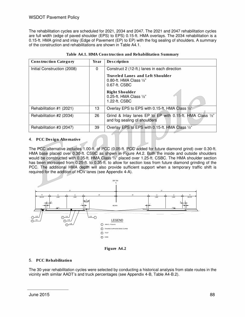
WSDOT Pavement Policy
June 2015 88
The rehabilitation cycles are scheduled for 2021, 2034 and 2047. The 2021 and 2047 rehabilitation cycles are full width (edge of paved shoulder (EPS) to EPS) 0.15-ft. HMA overlays. The 2034 rehabilitation is a 0.15-ft. HMA grind and inlay (Edge of Pavement (EP) to EP) with the fog sealing of shoulders. A summary of the construction and rehabilitations are shown in Table A4.1.
Table A4.1. HMA Construction and Rehabilitation Summary
Construction Category Year Description
Initial Construction (2008) 0 Construct 2 (12-ft.) lanes in each direction
Traveled Lanes and Left Shoulder 0.80-ft. HMA Class ½” 0.67-ft. CSBC
Right Shoulder 0.25-ft. HMA Class ½” 1.22-ft. CSBC
Rehabilitation #1 (2021) 13 Overlay EPS to EPS with 0.15-ft. HMA Class ½”
Rehabilitation #2 (2034) 26 Grind & Inlay lanes EP to EP with 0.15-ft. HMA Class ½” and fog sealing of shoulders
Rehabilitation #3 (2047) 39 Overlay EPS to EPS with 0.15-ft. HMA Class ½”
4. PCC Design Alternative
The PCC alternative includes 1.00-ft. of PCC (0.05-ft. PCC added for future diamond grind) over 0.30-ft. HMA base placed over 0.30-ft. CSBC as shown in Figure A4.2. Both the inside and outside shoulders would be constructed with 0.35-ft. HMA Class ½” placed over 1.25-ft. CSBC. The HMA shoulder section has been increased from 0.25-ft. to 0.35-ft. to allow for section loss from future diamond grinding of the PCC. The additional HMA depth will also provide sufficient support when a temporary traffic shift is required for the addition of HOV lanes (see Appendix 4-A).
Figure A4.2
5. PCC Rehabilitation
The 30-year rehabilitation cycles were selected by conducting a historical analysis from state routes in the vicinity with similar AADT’s and truck percentages (see Appendix 4-B, Table A4-B.2).
CL
SR 704
23
4'
SHLDR
10
1.252
0.35
23 10
MEDIAN
57 57
3
4
2
1.00
0.30
0.30
12
LANESHLDR
12
LANE
1
12
LANE SHLDR
12
LANE
VARIES VARIES
1' 1'
0.351
1'
LEGEND
CRUSHED SURFACING BASE COURSE
HMA CL. PG 64-221
2
3
4
PCCP
HMAB
1'
2'2'
WSDOT Pavement Policy
June 2015 89
Only one rehabilitation cycle is scheduled for 2038 to diamond grind the wearing surface, clean and reseal all joints and cracks. A summary of the construction and rehabilitation is shown in Table A4.2.
Table A4.2. PCC Construction and Rehabilitation Summary
Construction Category Year Description
Initial Construction (2008) 0 Construct 2 (12 ft.) lanes each direction
Mainline
1.00-ft. PCC 0.30-ft. HMA base 0.30-ft. CSBC
Shoulders
0.35-ft. HMA Class ½” 1.25-ft. CSBC
Rehabilitation #1 (2038) 30 PCC grinding, cleaning, reseal joints and cracks
II. Life Cycle Cost Analysis (LCCA)
1. The LCCA is based on the following parameters:
• Roadway Section: A one-mile section of roadway located between MP 3 and 4 was chosen to represent a typical section.
• Economic Variables: Estimated initial construction costs, future rehabilitation costs and user costs for this analysis are in 2005 dollars using a 4% discount rate.
• Traffic Data: The initial traffic volume of 15,000 ADT and annual growth factor of 1.92% were provided from a consulting firm contracted by the Olympia Design Office.
Initial construction will not have traffic; therefore, no user cost will be assessed.
• Truck Percentage o Single Unit Trucks (4.0%) o Combination Trucks (6.0%)
• Free Flow Capacity: The LCCA software calculated a Free Flow Capacity of 2137 based on the Transportation Research Board’s “1994 Highway Capacity Manual”.
• Traffic Speed during Work Zone Conditions: A 40 mph reduced speed limit was used during the work zone lane closure periods.
• Functional Classification: This highway was assigned a “Rural” functional classification due to its location and population density.
• Queue Dissipation Capacity: Queue Dissipation Capacity of 1,818 passenger cars/lane/hour was used for all rehabilitation cycles on both alternatives.
• Maximum ADT (Both Directions): The ADT for this analysis was capped at 140,000.
• Maximum Queue Length (Miles): On this project, a maximum queue length of 2.0 miles was assumed.
• Work Zone Capacity: The work zone capacity of 1,340 vehicles per hour per lane (vphpl) was used during lane closure periods.
WSDOT Pavement Policy
June 2015 90
• Day-time/Night-time Lane Closures: This hourly input is based on a 24-hour clock and marks the beginning and ending hours when a lane reduction will be in place during construction activities: o Day-time
– Inbound: 9:00 a.m. start time of lane closure and 5:00 p.m. for the reopening time. – Outbound: 6:00 a.m. start time of lane closure and 3:00 p.m. for the reopening time.
o Night-time – Inbound: 7:00 p.m. start time of lane closure and 5:00 a.m. for the reopening time. – Outbound: 7:00 p.m. start time of lane closure and 5:00 a.m. for the reopening time.
2. Estimates
The initial construction and future rehabilitation estimated costs were based on past WSDOT project bidding and do not represent the actual estimated cost to complete the project. Only items directly related to pavement construction are included (see Appendix 4-C).
3. LCCA Analysis Software
Real Cost Version 2.2.0 software was used to perform the analysis (see Appendix 4-D).
4. Results of LCCA
The Probabilistic Daytime and Nighttime results are shown in Tables A4.3 and A4.4 and the Deterministic in Tables A4.5 and A4.6 Table A4.7 is a summary for a side-by-comparison of the results and percent difference. The costs shown here represent the analyzed one-mile section and not the entire 6 mile project length.
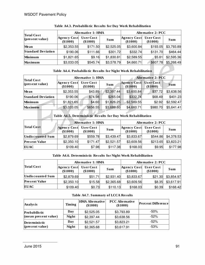
WSDOT Pavement Policy
June 2015 91
Table A4.3. Probabilistic Results for Day Work Rehabilitation
Total Cost (present value)
Alternative 1: HMA Alternative 2: PCC
Agency Cost ($1000)
User Cost ($1000)
Sum Agency Cost
($1000) User Cost
($1000) Sum
Mean $2,353.55 $171.50 $2,525.05 $3,600.84 $193.05 $3,793.89
Standard Deviation $190.06 $111.66 $301.72 $332.74 $131.70 $464.44
Minimum $1,821.65 $9.16 $1,830.81 $2,589.55 $5.81 $2,595.36
Maximum $3,033.05 $545.74 $3,578.79 $4,660.71 $607.78 $5,268.49
Table A4.4. Probabilistic Results for Night Work Rehabilitation
Total Cost (present value)
Alternative 1: HMA Alternative 2: PCC
Agency Cost ($1000)
User Cost ($1000)
Sum Agency Cost
($1000) User Cost
($1000) Sum
Mean $2,353.55 $43.89 $2,397.44 $3,600.84 $37.72 $3,638.56
Standard Deviation $190.06 $74.98 $265.04 $332.74 $68.49 $401.23
Minimum $1,821.65 $4.60 $1,826.25 $2,589.55 $2.92 $2,592.47
Maximum $3,033.05 $656.55 $3,689.60 $4,660.71 $980.70 $5,641.41
Table A4.5. Deterministic Results for Day Work Rehabilitation
Total Cost
Alternative 1: HMA Alternative 2: PCC
Agency Cost ($1000)
User Cost ($1000)
Sum Agency Cost
($1000) User Cost
($1000) Sum
Undiscounted Sum $2,879.69 $559.78 $3,439.47 $3,833.67 $544.86 $4,378.53
Present Value $2,350.10 $171.47 $2,521.57 $3,609.56 $213.65 $3,823.21
EUAC $109.40 $7.98 $117.38 $168.03 $9.95 $177.98
Table A4.6. Deterministic Results for Night Work Rehabilitation
Total Cost
Alternative 1: HMA Alternative 2: PCC
Agency Cost ($1000)
User Cost ($1000)
Sum Agency Cost
($1000) User Cost
($1000) Sum
Undiscounted Sum $2,879.69 $51.71 $2,931.40 $3,833.67 $21.30 $3,854.97
Present Value $2,350.10 $15.58 $2,365.68 $3,609.56 $8.35 $3,617.91
EUAC $109.40 $0.73 $110.13 $168.03 $0.39 $168.42
Table A4.7. Summary of LCCA Results
Analysis Timing HMA Alternative
($1000) PCC Alternative
($1000) Percent Difference
Probabilistic (mean present value)
Day $2,525.05 $3,793.89 -50%
Night $2,397.44 $3,638.56 -52%
Deterministic (present value)
Day $2,521.57 $3,823.21 -52%
Night $2,365.68 $3,617.91 -53%
WSDOT Pavement Policy
June 2015 92
III. Project specific externalities
Identification of project specific externalities is not required, since the cost difference between HMA and PCC alternatives is greater than 15%. The HMA alternative is between 50 and 53 % less than the PCCP alternative for all cases. The Olympic Region recommends the use of HMA for constructing SR 704. Use of HMA represents a substantial savings to WSDOT.
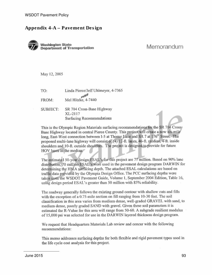
WSDOT Pavement Policy
June 2015 93
Appendix 4-A – Pavement Design
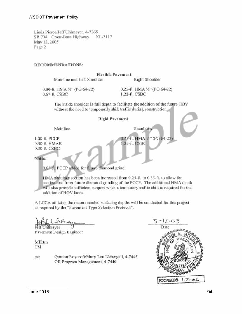
WSDOT Pavement Policy
June 2015 94
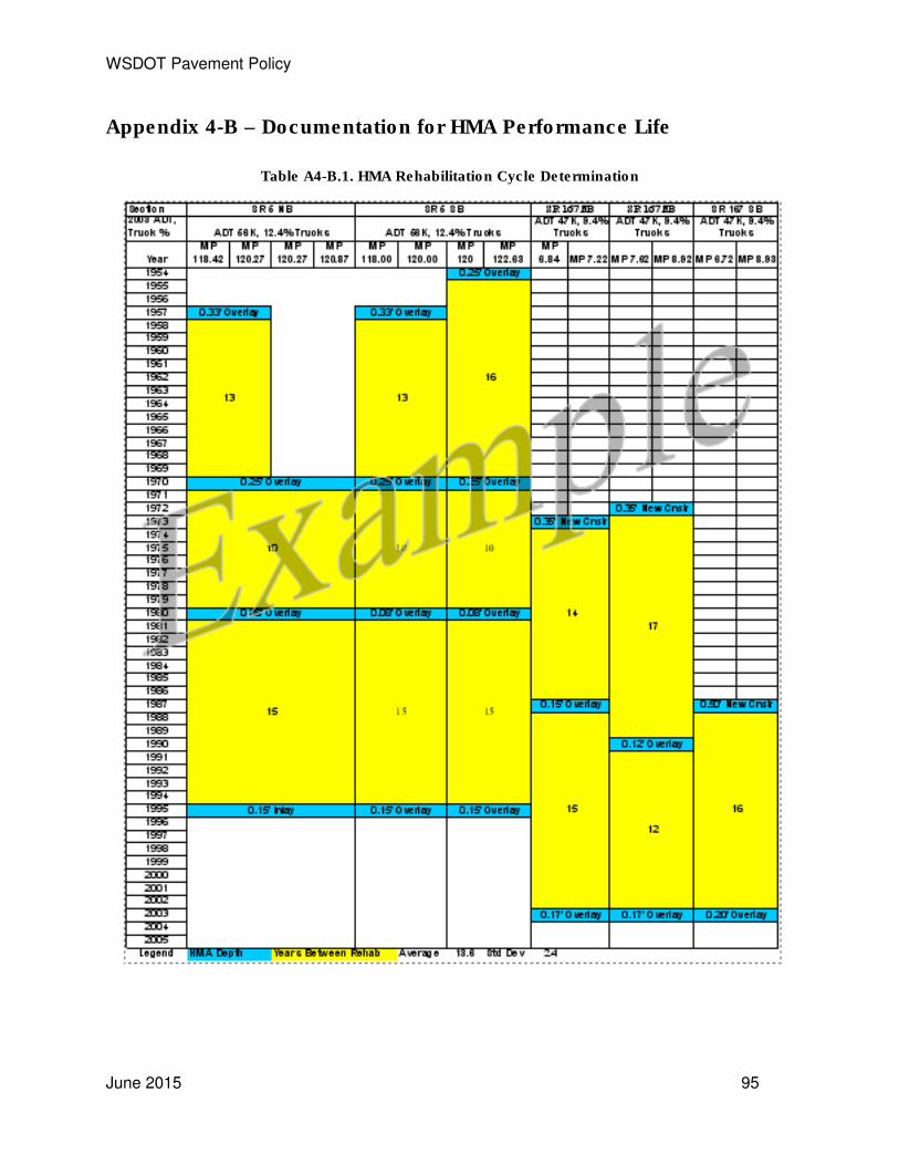
WSDOT Pavement Policy
June 2015 95
Appendix 4-B – Documentation for HMA Performance Life
Table A4-B.1. HMA Rehabilitation Cycle Determination
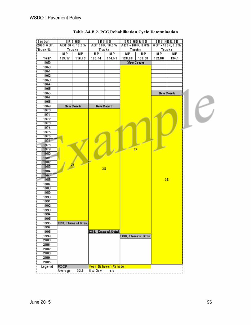
WSDOT Pavement Policy
June 2015 96
Table A4-B.2. PCC Rehabilitation Cycle Determination
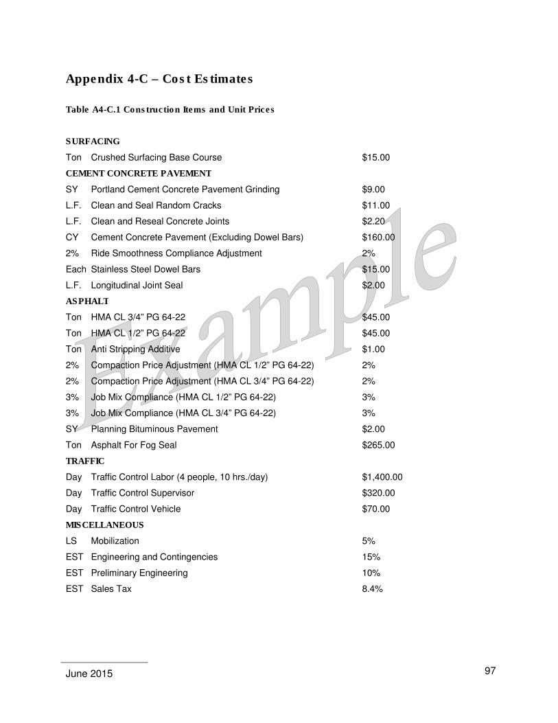
June 2015
97
Appendix 4-C – Cost Estimates
Table A4-C.1 Construction Items and Unit Prices
SURFACING
Ton Crushed Surfacing Base Course $15.00
CEMENT CONCRETE PAVEMENT
SY Portland Cement Concrete Pavement Grinding $9.00
L.F. Clean and Seal Random Cracks $11.00
L.F. Clean and Reseal Concrete Joints $2.20
CY Cement Concrete Pavement (Excluding Dowel Bars) $160.00
2% Ride Smoothness Compliance Adjustment 2%
Each Stainless Steel Dowel Bars $15.00
L.F. Longitudinal Joint Seal $2.00
ASPHALT
Ton HMA CL 3/4” PG 64-22 $45.00
Ton HMA CL 1/2” PG 64-22 $45.00
Ton Anti Stripping Additive $1.00
2% Compaction Price Adjustment (HMA CL 1/2” PG 64-22) 2%
2% Compaction Price Adjustment (HMA CL 3/4” PG 64-22) 2%
3% Job Mix Compliance (HMA CL 1/2” PG 64-22) 3%
3% Job Mix Compliance (HMA CL 3/4” PG 64-22) 3%
SY Planning Bituminous Pavement $2.00
Ton Asphalt For Fog Seal $265.00
TRAFFIC
Day Traffic Control Labor (4 people, 10 hrs./day) $1,400.00
Day Traffic Control Supervisor $320.00
Day Traffic Control Vehicle $70.00
MISCELLANEOUS
LS Mobilization 5%
EST Engineering and Contingencies 15%
EST Preliminary Engineering 10%
EST Sales Tax 8.4%

WSDOT Pavement Policy
June 2015
98
Table A4-C.2 Initial HMA Construction Year 2008
Detail: New HMA Construction - Lanes and Left Shoulder (0.80 ft HMA CL 1/2” PG 64-22 and 0.67 ft CSBC), Right Shoulder ( 0.25 ft HMA CL 1/2” PG 64-22 and 1.22 ft CSBC)
Quantity Unit Bid Item Unit
Price Amount
33,374 Ton Crushed Surfacing Base Course $15.00 $500,610
18,245 Ton HMA CL 1/2” PG 64-22 $45.00 $821,025
18,245 Ton Anti Stripping Additive $1.00 $18,245
$694,440 2% Compaction Price Adjustment (HMA CL 1/2” PG 64-22, 18,245 Tons-No shoulders) 2% $13,889
$821,025 3% Job Mix Compliance (HMA CL 1/2” PG 64-22) 3% $24,631
Items Subtotal $1,378,400
Mobilization (5% of Items Subtotal) $68,920 Use same value on PCCP Mobilization
Contract Items Subtotal (Items Incl. Mobilization) $1,447,320
Sales Tax (8.4% of Contract Items Subtotal) $121,575 Use same value on PCCP Sales Tax
Contract Subtotal (Contract Items Incl. Sales Tax) $1,568,895 Engineering and Contingencies (15% of Contract Subtotal) $235,334 Use same value on PCCP Engineering and
Contingencies
Total Construction Subtotal (Contract Incl. Engineering and Contingencies) $1,804,229 Preliminary Engineering (10% of Total Construction Subtotal) $180,423 Use same value on PCCP Preliminary
Engineering
Total Project Cost (Total Construction Incl. Preliminary Engineering) $1,984,652
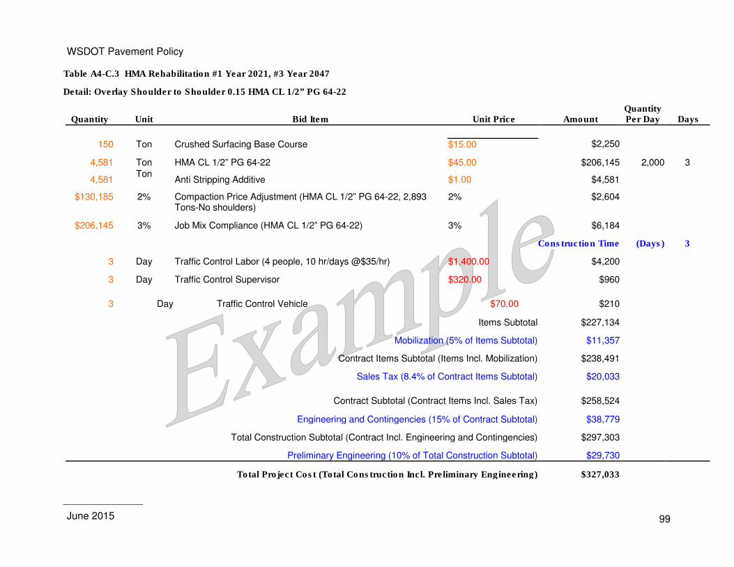
WSDOT Pavement Policy
June 2015
99
Table A4-C.3 HMA Rehabilitation #1 Year 2021, #3 Year 2047
Detail: Overlay Shoulder to Shoulder 0.15 HMA CL 1/2” PG 64-22
Quantity Unit Bid Item Unit Price Amount Quantity Per Day Days
150 Ton Crushed Surfacing Base Course $15.00 $2,250
4,581 Ton HMA CL 1/2” PG 64-22 $45.00 $206,145 2,000 3
4,581 Ton
Anti Stripping Additive $1.00 $4,581
$130,185 2% Compaction Price Adjustment (HMA CL 1/2” PG 64-22, 2,893 Tons-No shoulders)
2% $2,604
$206,145 3% Job Mix Compliance (HMA CL 1/2” PG 64-22) 3% $6,184
Construction Time (Days) 3
3 Day Traffic Control Labor (4 people, 10 hr/days @$35/hr) $1,400.00 $4,200
3 Day Traffic Control Supervisor $320.00 $960
3 Day Traffic Control Vehicle $70.00 $210
Items Subtotal $227,134
Mobilization (5% of Items Subtotal) $11,357
Contract Items Subtotal (Items Incl. Mobilization) $238,491
Sales Tax (8.4% of Contract Items Subtotal) $20,033
Contract Subtotal (Contract Items Incl. Sales Tax) $258,524
Engineering and Contingencies (15% of Contract Subtotal) $38,779
Total Construction Subtotal (Contract Incl. Engineering and Contingencies) $297,303
Preliminary Engineering (10% of Total Construction Subtotal) $29,730
Total Project Cost (Total Construction Incl. Preliminary Engineering) $327,033
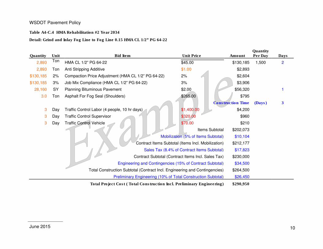
WSDOT Pavement Policy
June 2015
10
Table A4-C.4 HMA Rehabilitation #2 Year 2034
Detail: Grind and Inlay Fog Line to Fog Line 0.15 HMA CL 1/2” PG 64-22
Quantity Unit Bid Item Unit Price Amount Quantity Per Day Days
2,893 Ton HMA CL 1/2” PG 64-22 $45.00 $130,185 1,500 2
2,893 Ton Anti Stripping Additive $1.00 $2,893
$130,185 2% Compaction Price Adjustment (HMA CL 1/2” PG 64-22) 2% $2,604
$130,185 3% Job Mix Compliance (HMA CL 1/2” PG 64-22) 3% $3,906
28,160 SY Planning Bituminous Pavement $2.00 $56,320 1
3.0 Ton Asphalt For Fog Seal (Shoulders) $265.00 $795
Construction Time (Days) 3
3 Day Traffic Control Labor (4 people, 10 hr days) $1,400.00 $4,200
3 Day Traffic Control Supervisor $320.00 $960
3 Day Traffic Control Vehicle $70.00 $210
Items Subtotal $202,073
Mobilization (5% of Items Subtotal) $10,104
Contract Items Subtotal (Items Incl. Mobilization) $212,177
Sales Tax (8.4% of Contract Items Subtotal) $17,823
Contract Subtotal (Contract Items Incl. Sales Tax) $230,000
Engineering and Contingencies (15% of Contract Subtotal) $34,500
Total Construction Subtotal (Contract Incl. Engineering and Contingencies) $264,500
Preliminary Engineering (10% of Total Construction Subtotal) $26,450
Total Project Cost ( Total Construction Incl. Preliminary Engineering) $290,950

WSDOT Pavement Policy
June 2015
10
Table A4-C.5 Initial PCCP Construction Year 2008
Detail: PCCP New Construction 1.00 ft PCCP with Stainless Steel Dowel Bars on 0.30' HMA CL 3/4” PG 64-22 Base, 0.30’ CSBC, Shoulder 0.35' HMA CL 1/2” PG 64-22 w/ 1.25' CSBC
Quantity Unit Bid Item Unit Price Amount
10,169 CY Cement Concrete Pavement (Excluding Dowel Bars) $160.00 $1,627,040
14,120 EA Stainless Steel Dowel Bars $15.00 $211,800
50,036 L.F. Longitudinal Joint Seal $2.00 $100,072 $1,627,04
0 CALC Ride Smoothness Compliance Adjustment 2% $32,541
27,176 Ton Crushed Surfacing Base Course $15.00 $407,640
6,751 Ton HMA CL 3/4” PG 64-22 $45.00 $303,795
3,376 Ton HMA CL 1/2” PG 64-22 $45.00 $151,920
10,127 Ton Anti Stripping Additive $1.00 $10,127
$455,715 3% Job Mix Compliance (HMA CL 3/4” PG 64-22 & HMA CL 1/2” PG 64-22) 3% $13,671
Items Subtotal $2,858,606
Use HMA's Initial Construction Mobilization $68,920
Contract Items Subtotal (Items Incl. Mobilization) $2,927,526
Use HMA's Initial Construction Sale Tax $121,575
Contract Subtotal (Contract Items Incl. Sales Tax) $3,049,101
Use HMA's Initial Construction Engineering and Contingencies $235,334
Total Construction Subtotal (Contract Incl. Engineering and Contingencies) $3,284,435
Use HMA's Initial Construction Preliminary Engineering $180,423
Total Project Cost ( Total Construction Incl. Preliminary Engineering) $3,464,858
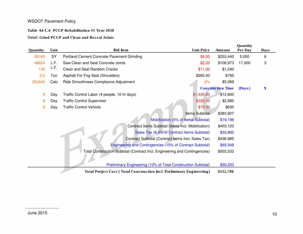
WSDOT Pavement Policy
June 2015
10
Table A4-C.6 PCCP Rehabilitation #1 Year 2038
Detail: Grind PCCP and Clean and Reseal Joints
Quantity Unit Bid Item Unit Price Amount Quantity Per Day Days
28160 SY Portland Cement Concrete Pavement Grinding $9.00 $253,440 5,000 6
48624 L.F. Saw Clean and Seal Concrete Joints $2.20 $106,973 17,000 3
140 L.F. Clean and Seal Random Cracks $11.00 $1,540
3.0 Ton Asphalt For Fog Seal (Shoulders) $265.00 $795
253440 Calc Ride Smoothness Compliance Adjustment 2% $5,069
Construction Time (Days) 9
9 Day Traffic Control Labor (4 people, 10 hr days) $1,400.00 $12,600
9 Day Traffic Control Supervisor $320.00 $2,880
9 Day Traffic Control Vehicle $70.00 $630
Items Subtotal $383,927
Mobilization (5% of Items Subtotal) $19,196
Contract Items Subtotal (Items Incl. Mobilization) $403,123
Sales Tax (8.4% of Contract Items Subtotal) $33,862
Contract Subtotal (Contract Items Incl. Sales Tax) $436,985
Engineering and Contingencies (15% of Contract Subtotal) $65,548
Total Construction Subtotal (Contract Incl. Engineering and Contingencies) $502,533
Preliminary Engineering (10% of Total Construction Subtotal) $50,253
Total Project Cost ( Total Construction Incl. Preliminary Engineering) $552,786
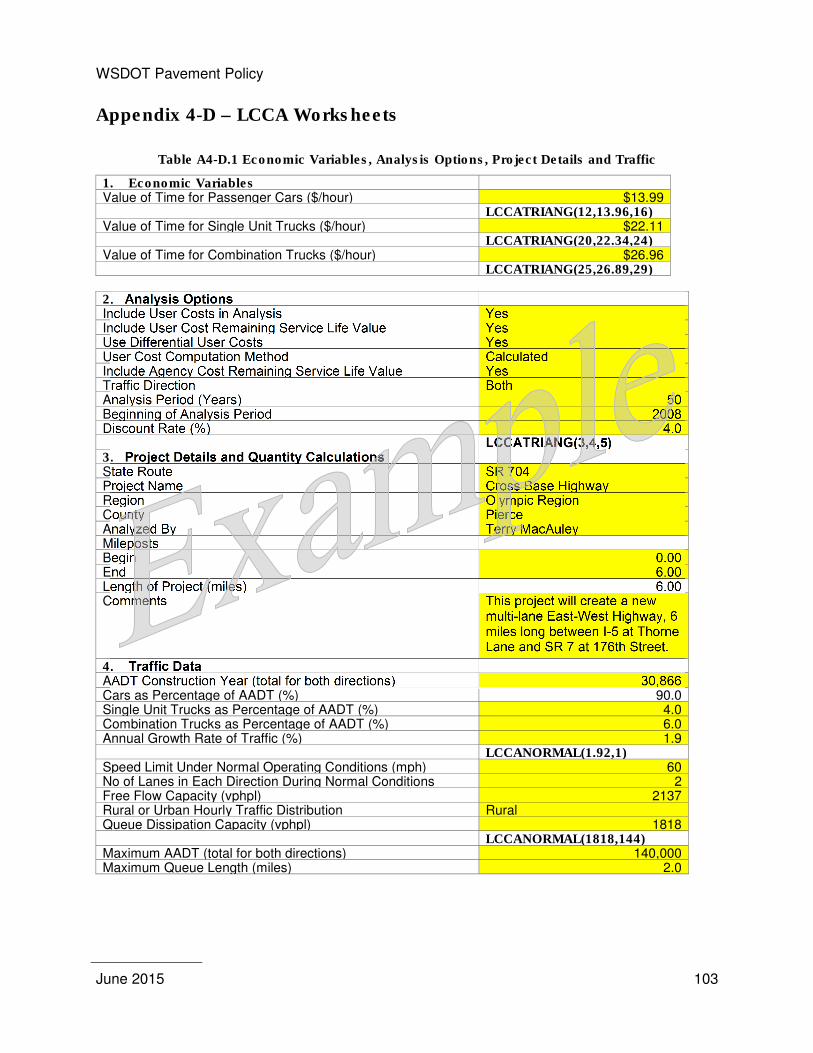
WSDOT Pavement Policy
June 2015
103
Appendix 4-D – LCCA Worksheets
Table A4-D.1 Economic Variables, Analysis Options, Project Details and Traffic
1. Economic Variables Value of Time for Passenger Cars ($/hour) $13.99 LCCATRIANG(12,13.96,16) Value of Time for Single Unit Trucks ($/hour) $22.11 LCCATRIANG(20,22.34,24) Value of Time for Combination Trucks ($/hour) $26.96 LCCATRIANG(25,26.89,29)
2. Analysis Options Include User Costs in Analysis Yes Include User Cost Remaining Service Life Value Yes Use Differential User Costs Yes User Cost Computation Method Calculated Include Agency Cost Remaining Service Life Value Yes Traffic Direction Both Analysis Period (Years) 50 Beginning of Analysis Period 2008 Discount Rate (%) 4.0 LCCATRIANG(3,4,5) 3. Project Details and Quantity Calculations State Route SR 704 Project Name Cross Base Highway Region Olympic Region County Pierce Analyzed By Terry MacAuley Mileposts Begin 0.00 End 6.00 Length of Project (miles) 6.00 Comments This project will create a new
multi-lane East-West Highway, 6 miles long between I-5 at Thorne Lane and SR 7 at 176th Street.
4. Traffic Data AADT Construction Year (total for both directions) 30,866 Cars as Percentage of AADT (%) 90.0 Single Unit Trucks as Percentage of AADT (%) 4.0 Combination Trucks as Percentage of AADT (%) 6.0 Annual Growth Rate of Traffic (%) 1.9 LCCANORMAL(1.92,1) Speed Limit Under Normal Operating Conditions (mph) 60 No of Lanes in Each Direction During Normal Conditions 2 Free Flow Capacity (vphpl) 2137 Rural or Urban Hourly Traffic Distribution Rural Queue Dissipation Capacity (vphpl) 1818 LCCANORMAL(1818,144) Maximum AADT (total for both directions) 140,000 Maximum Queue Length (miles) 2.0
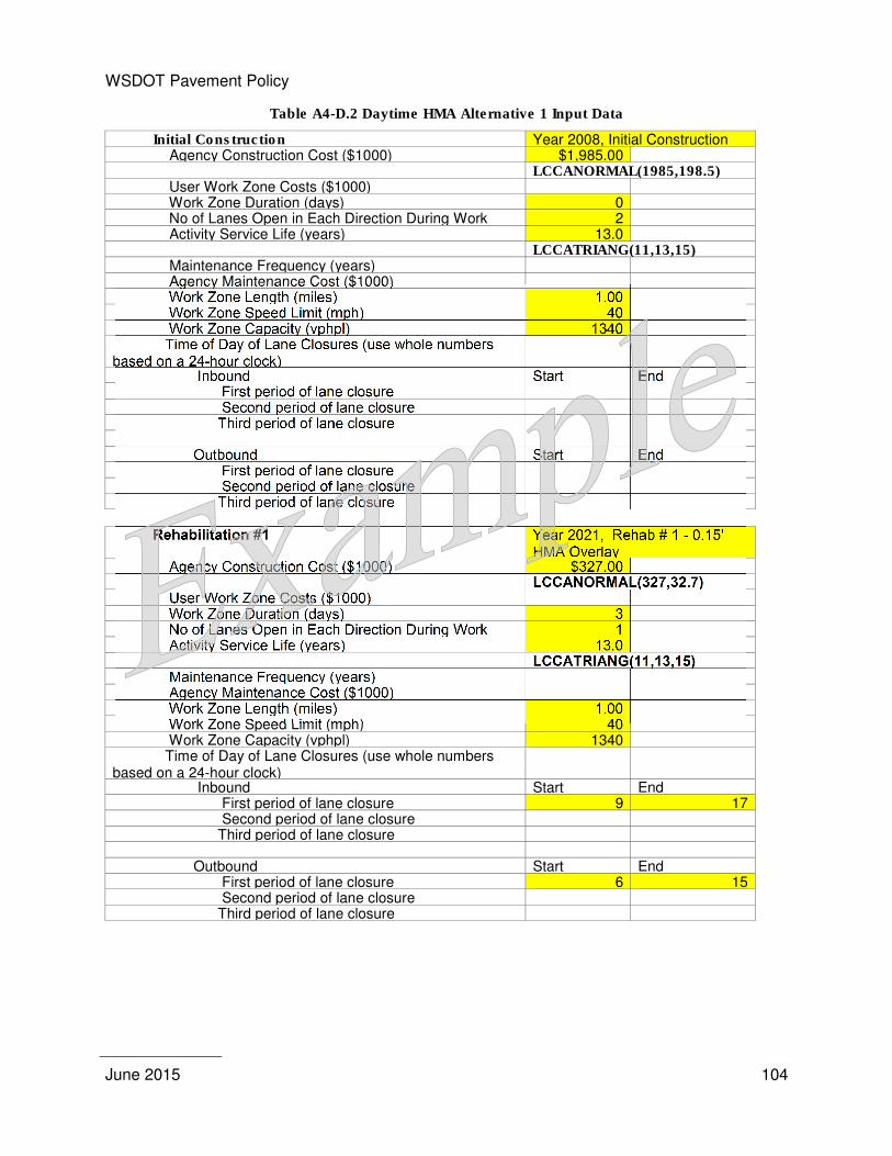
WSDOT Pavement Policy
June 2015
104
Table A4-D.2 Daytime HMA Alternative 1 Input Data
Initial Construction Year 2008, Initial Construction Agency Construction Cost ($1000) $1,985.00 LCCANORMAL(1985,198.5) User Work Zone Costs ($1000) Work Zone Duration (days) 0 No of Lanes Open in Each Direction During Work 2 Activity Service Life (years) 13.0 LCCATRIANG(11,13,15) Maintenance Frequency (years) Agency Maintenance Cost ($1000) Work Zone Length (miles) 1.00 Work Zone Speed Limit (mph) 40 Work Zone Capacity (vphpl) 1340 Time of Day of Lane Closures (use whole numbers based on a 24-hour clock)
Inbound Start End First period of lane closure Second period of lane closure Third period of lane closure Outbound Start End First period of lane closure Second period of lane closure Third period of lane closure
Rehabilitation #1 Year 2021, Rehab # 1 - 0.15'
HMA Overlay Agency Construction Cost ($1000) $327.00 LCCANORMAL(327,32.7) User Work Zone Costs ($1000) Work Zone Duration (days) 3 No of Lanes Open in Each Direction During Work 1 Activity Service Life (years) 13.0 LCCATRIANG(11,13,15) Maintenance Frequency (years) Agency Maintenance Cost ($1000) Work Zone Length (miles) 1.00 Work Zone Speed Limit (mph) 40 Work Zone Capacity (vphpl) 1340 Time of Day of Lane Closures (use whole numbers based on a 24-hour clock)
Inbound Start End First period of lane closure 9 17 Second period of lane closure Third period of lane closure Outbound Start End First period of lane closure 6 15 Second period of lane closure Third period of lane closure
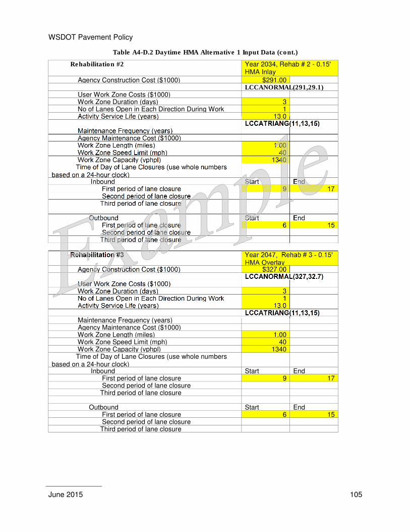
WSDOT Pavement Policy
June 2015
105
Table A4-D.2 Daytime HMA Alternative 1 Input Data (cont.)
Rehabilitation #2 Year 2034, Rehab # 2 - 0.15' HMA Inlay
Agency Construction Cost ($1000) $291.00 LCCANORMAL(291,29.1) User Work Zone Costs ($1000) Work Zone Duration (days) 3 No of Lanes Open in Each Direction During Work 1 Activity Service Life (years) 13.0 LCCATRIANG(11,13,15) Maintenance Frequency (years) Agency Maintenance Cost ($1000) Work Zone Length (miles) 1.00 Work Zone Speed Limit (mph) 40 Work Zone Capacity (vphpl) 1340 Time of Day of Lane Closures (use whole numbers based on a 24-hour clock)
Inbound Start End First period of lane closure 9 17 Second period of lane closure Third period of lane closure Outbound Start End First period of lane closure 6 15 Second period of lane closure Third period of lane closure
Rehabilitation #3 Year 2047, Rehab # 3 - 0.15'
HMA Overlay Agency Construction Cost ($1000) $327.00 LCCANORMAL(327,32.7) User Work Zone Costs ($1000) Work Zone Duration (days) 3 No of Lanes Open in Each Direction During Work 1 Activity Service Life (years) 13.0 LCCATRIANG(11,13,15) Maintenance Frequency (years) Agency Maintenance Cost ($1000) Work Zone Length (miles) 1.00 Work Zone Speed Limit (mph) 40 Work Zone Capacity (vphpl) 1340 Time of Day of Lane Closures (use whole numbers based on a 24-hour clock)
Inbound Start End First period of lane closure 9 17 Second period of lane closure Third period of lane closure Outbound Start End First period of lane closure 6 15 Second period of lane closure Third period of lane closure
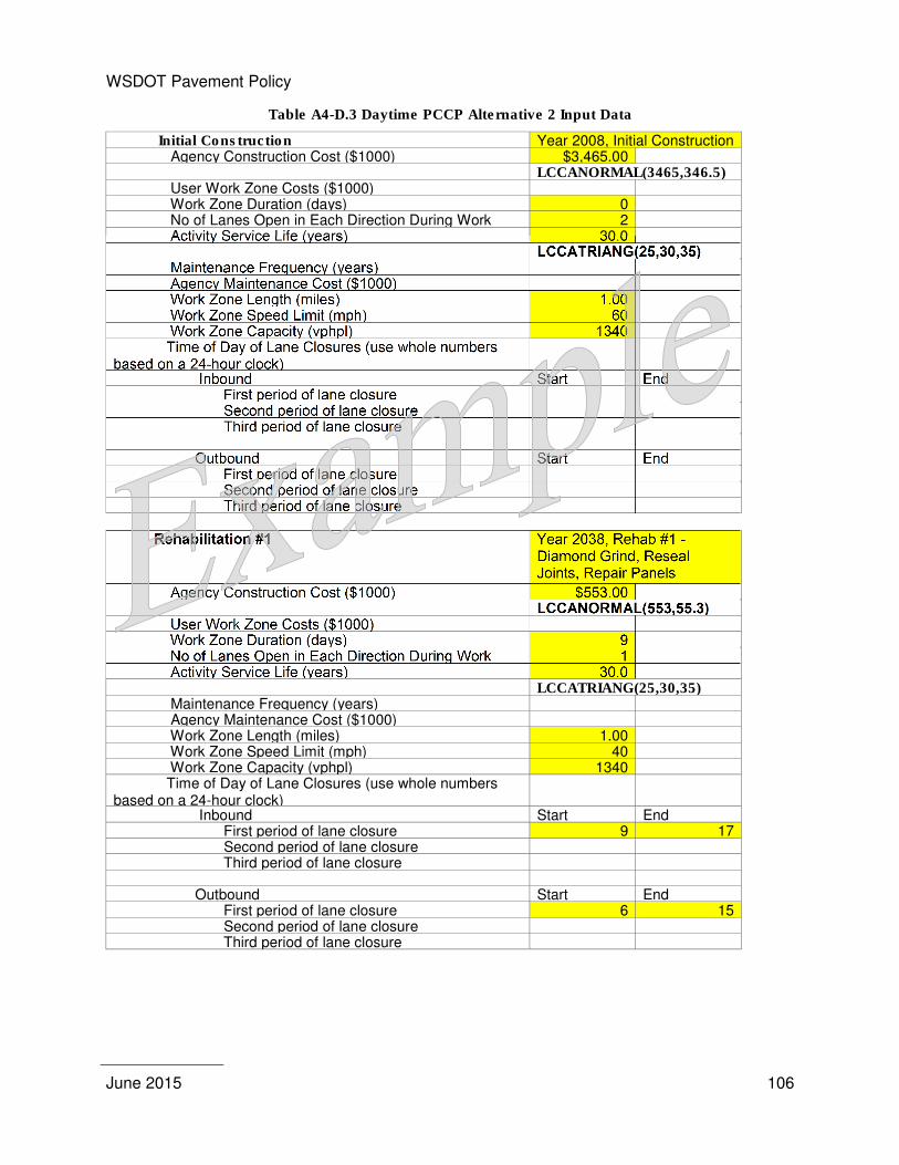
WSDOT Pavement Policy
June 2015
106
Table A4-D.3 Daytime PCCP Alternative 2 Input Data
Initial Construction Year 2008, Initial Construction Agency Construction Cost ($1000) $3,465.00 LCCANORMAL(3465,346.5) User Work Zone Costs ($1000) Work Zone Duration (days) 0 No of Lanes Open in Each Direction During Work 2 Activity Service Life (years) 30.0 LCCATRIANG(25,30,35) Maintenance Frequency (years) Agency Maintenance Cost ($1000) Work Zone Length (miles) 1.00 Work Zone Speed Limit (mph) 60 Work Zone Capacity (vphpl) 1340 Time of Day of Lane Closures (use whole numbers based on a 24-hour clock)
Inbound Start End First period of lane closure Second period of lane closure Third period of lane closure Outbound Start End First period of lane closure Second period of lane closure Third period of lane closure
Rehabilitation #1 Year 2038, Rehab #1 -
Diamond Grind, Reseal Joints, Repair Panels
Agency Construction Cost ($1000) $553.00 LCCANORMAL(553,55.3) User Work Zone Costs ($1000) Work Zone Duration (days) 9 No of Lanes Open in Each Direction During Work 1 Activity Service Life (years) 30.0 LCCATRIANG(25,30,35) Maintenance Frequency (years) Agency Maintenance Cost ($1000) Work Zone Length (miles) 1.00 Work Zone Speed Limit (mph) 40 Work Zone Capacity (vphpl) 1340 Time of Day of Lane Closures (use whole numbers based on a 24-hour clock)
Inbound Start End First period of lane closure 9 17 Second period of lane closure Third period of lane closure Outbound Start End First period of lane closure 6 15 Second period of lane closure Third period of lane closure
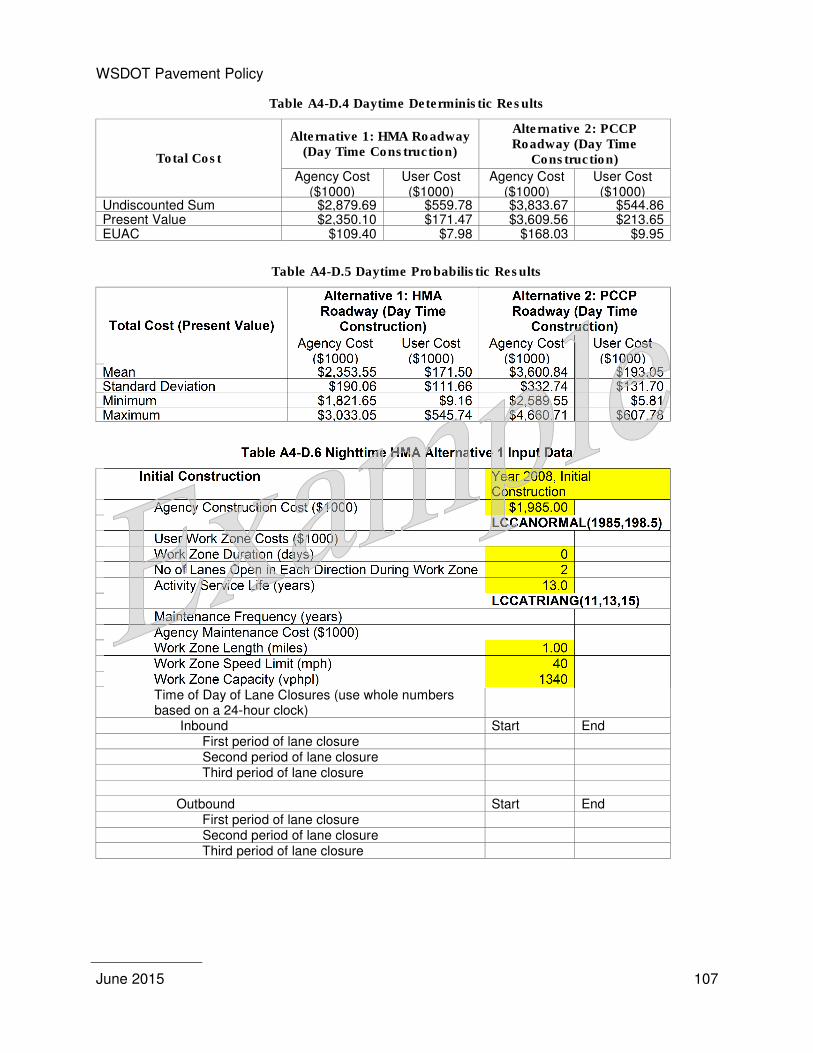
WSDOT Pavement Policy
June 2015
107
Table A4-D.4 Daytime Deterministic Results
Total Cost
Alternative 1: HMA Roadway (Day Time Construction)
Alternative 2: PCCP Roadway (Day Time
Construction)
Agency Cost ($1000)
User Cost ($1000)
Agency Cost ($1000)
User Cost ($1000)
Undiscounted Sum $2,879.69 $559.78 $3,833.67 $544.86 Present Value $2,350.10 $171.47 $3,609.56 $213.65 EUAC $109.40 $7.98 $168.03 $9.95
Table A4-D.5 Daytime Probabilistic Results
Total Cost (Present Value)
Alternative 1: HMA Roadway (Day Time
Construction)
Alternative 2: PCCP Roadway (Day Time
Construction)
Agency Cost ($1000)
User Cost ($1000)
Agency Cost ($1000)
User Cost ($1000)
Mean $2,353.55 $171.50 $3,600.84 $193.05 Standard Deviation $190.06 $111.66 $332.74 $131.70 Minimum $1,821.65 $9.16 $2,589.55 $5.81 Maximum $3,033.05 $545.74 $4,660.71 $607.78
Table A4-D.6 Nighttime HMA Alternative 1 Input Data
Initial Construction Year 2008, Initial Construction
Agency Construction Cost ($1000) $1,985.00 LCCANORMAL(1985,198.5) User Work Zone Costs ($1000) Work Zone Duration (days) 0 No of Lanes Open in Each Direction During Work Zone 2 Activity Service Life (years) 13.0 LCCATRIANG(11,13,15) Maintenance Frequency (years) Agency Maintenance Cost ($1000) Work Zone Length (miles) 1.00 Work Zone Speed Limit (mph) 40 Work Zone Capacity (vphpl) 1340 Time of Day of Lane Closures (use whole numbers based on a 24-hour clock)
Inbound Start End First period of lane closure Second period of lane closure Third period of lane closure Outbound Start End First period of lane closure Second period of lane closure Third period of lane closure
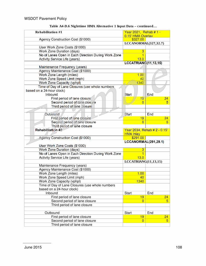
WSDOT Pavement Policy
June 2015
108
Table A4-D.6 Nighttime HMA Alternative 1 Input Data – continued…
Rehabilitation #1 Year 2021, Rehab # 1 - 0.15' HMA Overlay
Agency Construction Cost ($1000) $327.00 LCCANORMAL(327,32.7) User Work Zone Costs ($1000) Work Zone Duration (days) 3 No of Lanes Open in Each Direction During Work Zone 1 Activity Service Life (years) 13.0 LCCATRIANG(11,13,15) Maintenance Frequency (years) Agency Maintenance Cost ($1000) Work Zone Length (miles) 1.00 Work Zone Speed Limit (mph) 40 Work Zone Capacity (vphpl) 1340 Time of Day of Lane Closures (use whole numbers based on a 24-hour clock)
Inbound Start End First period of lane closure 19 24 Second period of lane closure 0 5 Third period of lane closure Outbound Start End First period of lane closure 19 24 Second period of lane closure 0 5 Third period of lane closure Rehabilitation #2 Year 2034, Rehab # 2 - 0.15'
HMA Inlay Agency Construction Cost ($1000) $291.00 LCCANORMAL(291,29.1) User Work Zone Costs ($1000) Work Zone Duration (days) 3 No of Lanes Open in Each Direction During Work Zone 1 Activity Service Life (years) 13.0 LCCATRIANG(11,13,15) Maintenance Frequency (years) Agency Maintenance Cost ($1000) Work Zone Length (miles) 1.00 Work Zone Speed Limit (mph) 40 Work Zone Capacity (vphpl) 1340 Time of Day of Lane Closures (use whole numbers based on a 24-hour clock)
Inbound Start End First period of lane closure 19 24 Second period of lane closure 0 5 Third period of lane closure Outbound Start End First period of lane closure 19 24 Second period of lane closure 0 5 Third period of lane closure
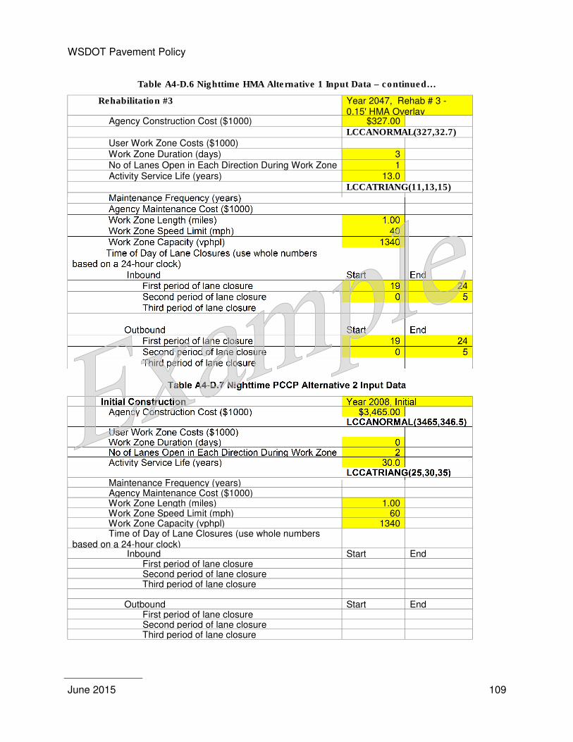
WSDOT Pavement Policy
June 2015
109
Table A4-D.6 Nighttime HMA Alternative 1 Input Data – continued…
Rehabilitation #3 Year 2047, Rehab # 3 - 0.15' HMA Overlay
Agency Construction Cost ($1000) $327.00 LCCANORMAL(327,32.7) User Work Zone Costs ($1000) Work Zone Duration (days) 3 No of Lanes Open in Each Direction During Work Zone 1 Activity Service Life (years) 13.0 LCCATRIANG(11,13,15) Maintenance Frequency (years) Agency Maintenance Cost ($1000) Work Zone Length (miles) 1.00 Work Zone Speed Limit (mph) 40 Work Zone Capacity (vphpl) 1340 Time of Day of Lane Closures (use whole numbers based on a 24-hour clock)
Inbound Start End First period of lane closure 19 24 Second period of lane closure 0 5 Third period of lane closure Outbound Start End First period of lane closure 19 24 Second period of lane closure 0 5 Third period of lane closure
Table A4-D.7 Nighttime PCCP Alternative 2 Input Data
Initial Construction Year 2008, Initial Agency Construction Cost ($1000) $3,465.00 LCCANORMAL(3465,346.5) User Work Zone Costs ($1000) Work Zone Duration (days) 0 No of Lanes Open in Each Direction During Work Zone 2 Activity Service Life (years) 30.0 LCCATRIANG(25,30,35) Maintenance Frequency (years) Agency Maintenance Cost ($1000) Work Zone Length (miles) 1.00 Work Zone Speed Limit (mph) 60 Work Zone Capacity (vphpl) 1340 Time of Day of Lane Closures (use whole numbers based on a 24-hour clock)
Inbound Start End First period of lane closure Second period of lane closure Third period of lane closure Outbound Start End First period of lane closure Second period of lane closure Third period of lane closure
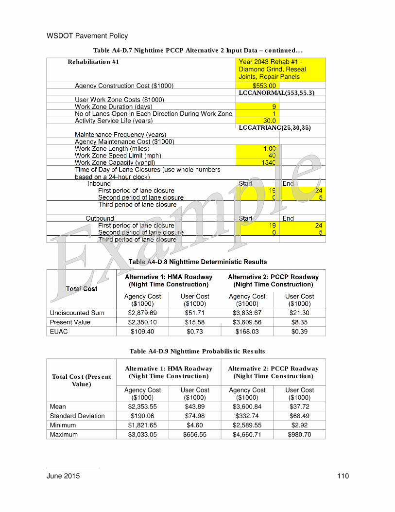
WSDOT Pavement Policy
June 2015
110
Table A4-D.7 Nighttime PCCP Alternative 2 Input Data – continued…
Rehabilitation #1 Year 2043 Rehab #1 - Diamond Grind, Reseal Joints, Repair Panels
Agency Construction Cost ($1000) $553.00 LCCANORMAL(553,55.3) User Work Zone Costs ($1000) Work Zone Duration (days) 9 No of Lanes Open in Each Direction During Work Zone 1 Activity Service Life (years) 30.0 LCCATRIANG(25,30,35) Maintenance Frequency (years) Agency Maintenance Cost ($1000) Work Zone Length (miles) 1.00 Work Zone Speed Limit (mph) 40 Work Zone Capacity (vphpl) 1340 Time of Day of Lane Closures (use whole numbers based on a 24-hour clock)
Inbound Start End First period of lane closure 19 24 Second period of lane closure 0 5 Third period of lane closure Outbound Start End First period of lane closure 19 24 Second period of lane closure 0 5 Third period of lane closure
Table A4-D.8 Nighttime Deterministic Results
Total Cost
Alternative 1: HMA Roadway (Night Time Construction)
Alternative 2: PCCP Roadway (Night Time Construction)
Agency Cost ($1000)
User Cost ($1000)
Agency Cost ($1000)
User Cost ($1000)
Undiscounted Sum $2,879.69 $51.71 $3,833.67 $21.30
Present Value $2,350.10 $15.58 $3,609.56 $8.35
EUAC $109.40 $0.73 $168.03 $0.39
Table A4-D.9 Nighttime Probabilistic Results
Total Cost (Present Value)
Alternative 1: HMA Roadway (Night Time Construction)
Alternative 2: PCCP Roadway (Night Time Construction)
Agency Cost ($1000)
User Cost ($1000)
Agency Cost ($1000)
User Cost ($1000)
Mean $2,353.55 $43.89 $3,600.84 $37.72
Standard Deviation $190.06 $74.98 $332.74 $68.49
Minimum $1,821.65 $4.60 $2,589.55 $2.92
Maximum $3,033.05 $656.55 $4,660.71 $980.70
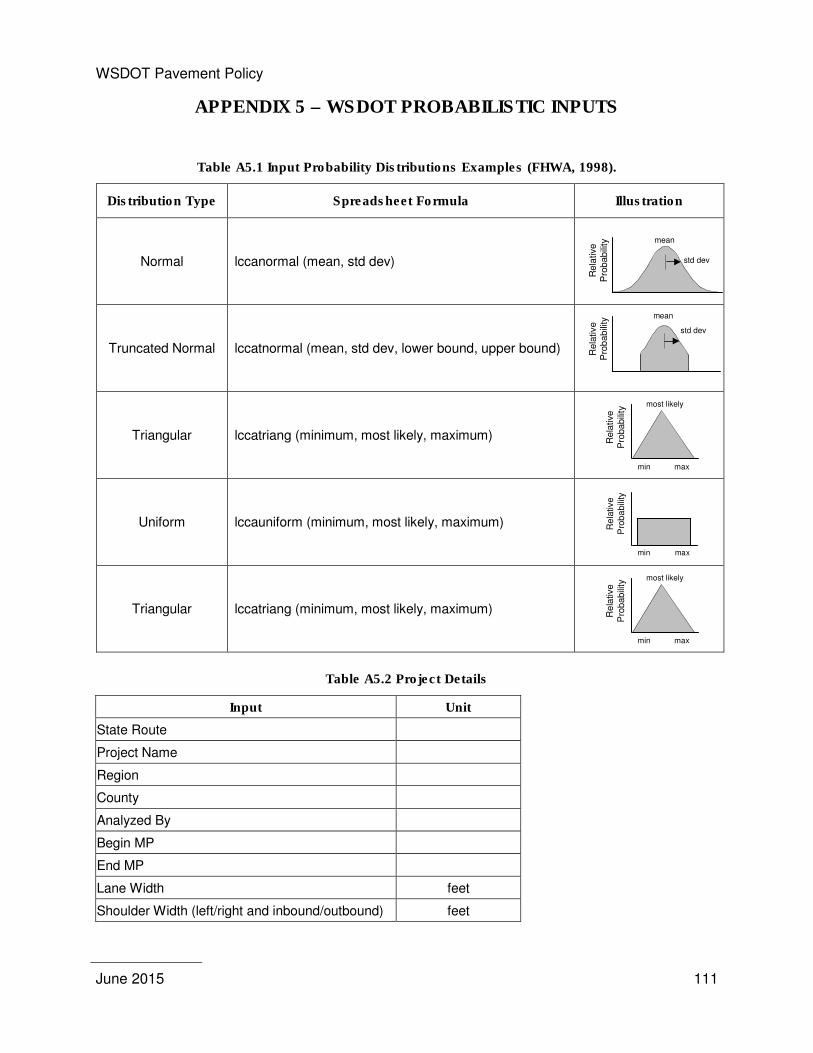
WSDOT Pavement Policy
June 2015
111
APPENDIX 5 – WSDOT PROBABILISTIC INPUTS
Table A5.1 Input Probability Distributions Examples (FHWA, 1998).
Distribution Type Spreadsheet Formula Illustration
Normal lccanormal (mean, std dev)
Truncated Normal lccatnormal (mean, std dev, lower bound, upper bound)
Rela
tive
Pro
babili
ty mean
std dev
Triangular lccatriang (minimum, most likely, maximum)
Uniform lccauniform (minimum, most likely, maximum)
min max
Rela
tive
Pro
ba
bili
ty
Triangular lccatriang (minimum, most likely, maximum)
Table A5.2 Project Details
Input Unit
State Route
Project Name
Region
County
Analyzed By
Begin MP
End MP
Lane Width feet
Shoulder Width (left/right and inbound/outbound) feet
Re
lative
Pro
bab
ility mean
std dev
min max
most likely
Rela
tive
Pro
babili
ty
min max
most likely
Rela
tive
Pro
babili
ty
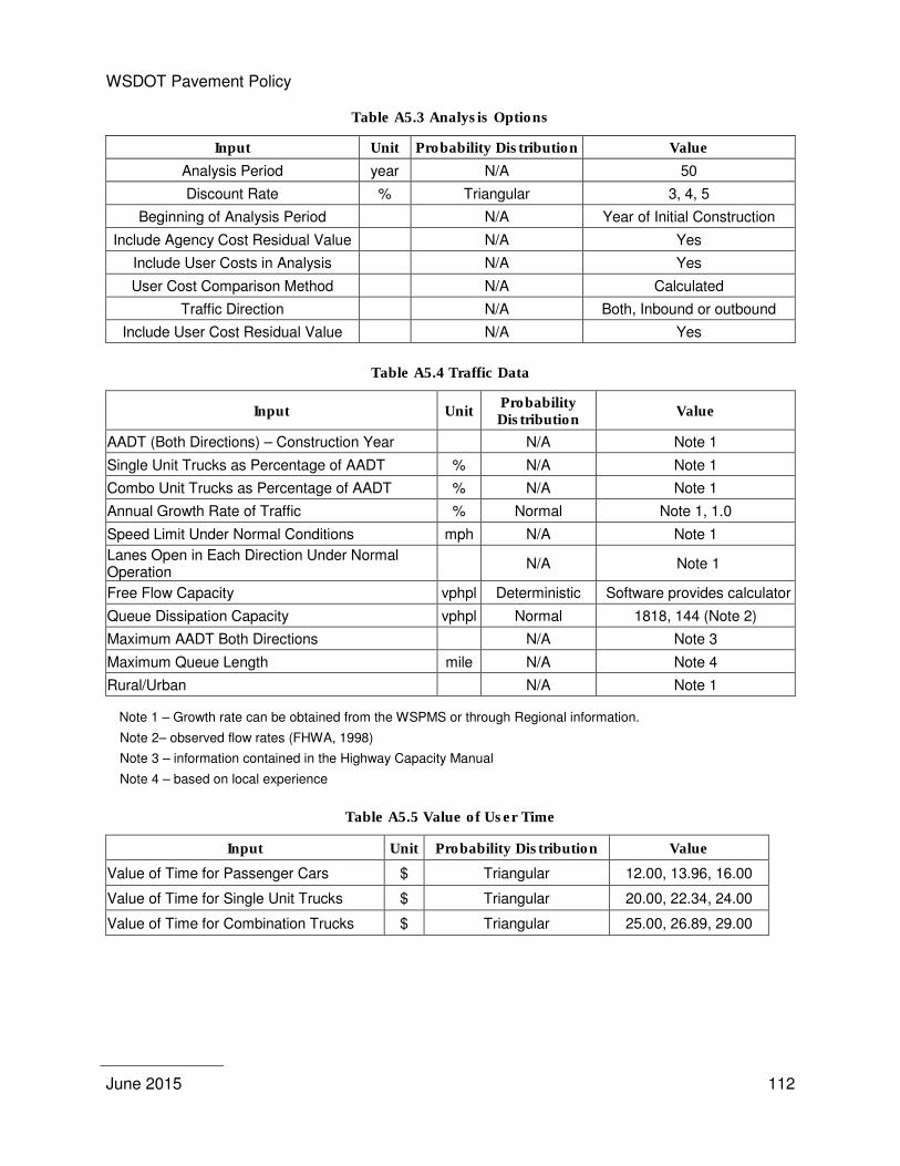
WSDOT Pavement Policy
June 2015
112
Table A5.3 Analysis Options
Input Unit Probability Distribution Value
Analysis Period year N/A 50
Discount Rate % Triangular 3, 4, 5
Beginning of Analysis Period N/A Year of Initial Construction
Include Agency Cost Residual Value N/A Yes
Include User Costs in Analysis N/A Yes
User Cost Comparison Method N/A Calculated
Traffic Direction N/A Both, Inbound or outbound
Include User Cost Residual Value N/A Yes
Table A5.4 Traffic Data
Input Unit Probability Distribution
Value
AADT (Both Directions) – Construction Year N/A Note 1
Single Unit Trucks as Percentage of AADT % N/A Note 1
Combo Unit Trucks as Percentage of AADT % N/A Note 1
Annual Growth Rate of Traffic % Normal Note 1, 1.0
Speed Limit Under Normal Conditions mph N/A Note 1
Lanes Open in Each Direction Under Normal Operation
N/A Note 1
Free Flow Capacity vphpl Deterministic Software provides calculator
Queue Dissipation Capacity vphpl Normal 1818, 144 (Note 2)
Maximum AADT Both Directions N/A Note 3
Maximum Queue Length mile N/A Note 4
Rural/Urban N/A Note 1
Note 1 – Growth rate can be obtained from the WSPMS or through Regional information.
Note 2– observed flow rates (FHWA, 1998)
Note 3 – information contained in the Highway Capacity Manual
Note 4 – based on local experience
Table A5.5 Value of User Time
Input Unit Probability Distribution Value
Value of Time for Passenger Cars $ Triangular 12.00, 13.96, 16.00
Value of Time for Single Unit Trucks $ Triangular 20.00, 22.34, 24.00
Value of Time for Combination Trucks $ Triangular 25.00, 26.89, 29.00
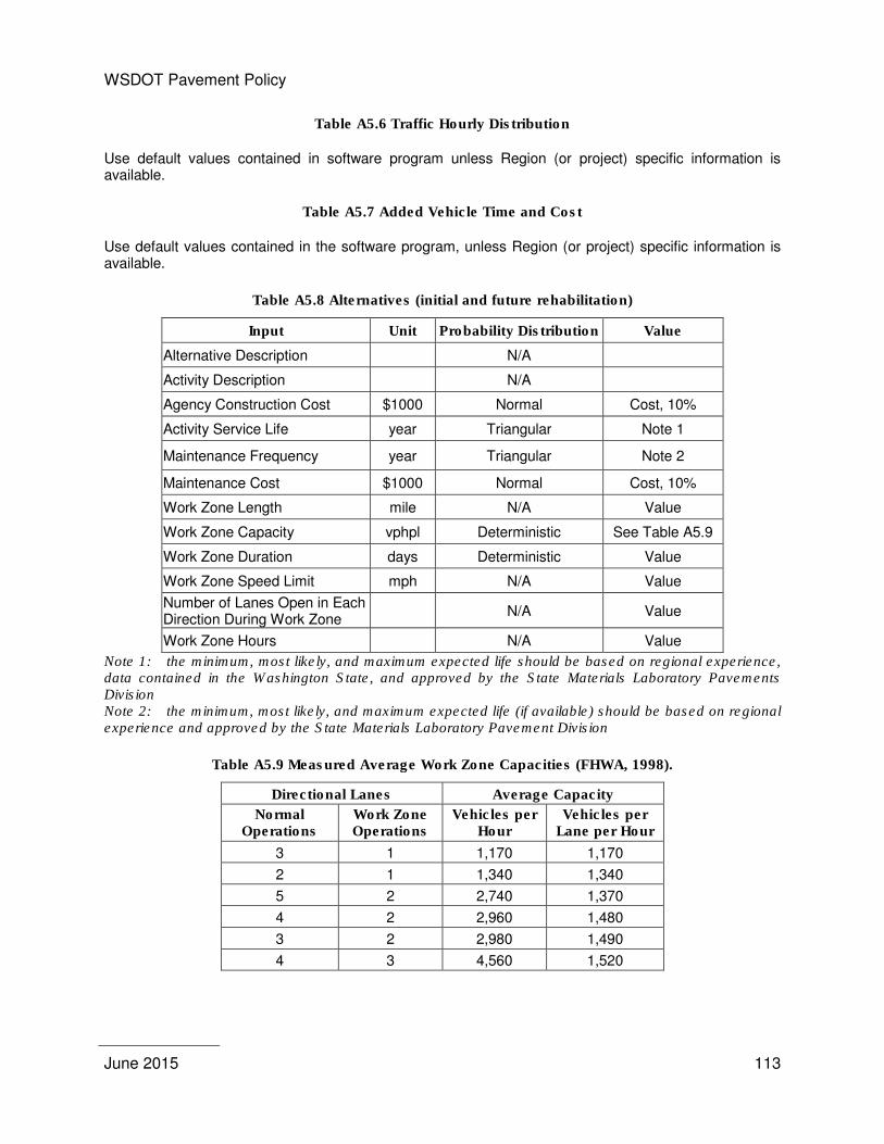
WSDOT Pavement Policy
June 2015
113
Table A5.6 Traffic Hourly Distribution
Use default values contained in software program unless Region (or project) specific information is available.
Table A5.7 Added Vehicle Time and Cost
Use default values contained in the software program, unless Region (or project) specific information is available.
Table A5.8 Alternatives (initial and future rehabilitation)
Input Unit Probability Distribution Value
Alternative Description N/A
Activity Description N/A
Agency Construction Cost $1000 Normal Cost, 10%
Activity Service Life year Triangular Note 1
Maintenance Frequency year Triangular Note 2
Maintenance Cost $1000 Normal Cost, 10%
Work Zone Length mile N/A Value
Work Zone Capacity vphpl Deterministic See Table A5.9
Work Zone Duration days Deterministic Value
Work Zone Speed Limit mph N/A Value
Number of Lanes Open in Each Direction During Work Zone
N/A Value
Work Zone Hours N/A Value
Note 1: the minimum, most likely, and maximum expected life should be based on regional experience, data contained in the Washington State, and approved by the State Materials Laboratory Pavements Division Note 2: the minimum, most likely, and maximum expected life (if available) should be based on regional experience and approved by the State Materials Laboratory Pavement Division
Table A5.9 Measured Average Work Zone Capacities (FHWA, 1998).
Directional Lanes Average Capacity
Normal Operations
Work Zone Operations
Vehicles per Hour
Vehicles per Lane per Hour
3 1 1,170 1,170
2 1 1,340 1,340
5 2 2,740 1,370
4 2 2,960 1,480
3 2 2,980 1,490
4 3 4,560 1,520

WSDOT Pavement Policy
June 2015
114
Reference
Federal Highway Administration (FHWA), (1998). Life cycle Cost Analysis in Pavement Design, FHWA-SA-98-079 (1998).
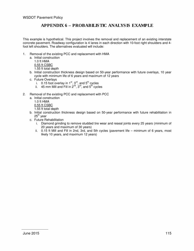
WSDOT Pavement Policy
June 2015
115
APPENDIX 6 – PROBABILISTIC ANALYSIS EXAMPLE
This example is hypothetical. This project involves the removal and replacement of an existing interstate concrete pavement. Roadway configuration is 4 lanes in each direction with 10-foot right shoulders and 4-foot left shoulders. The alternatives evaluated will include:
1. Removal of the existing PCC and replacement with HMA a. Initial construction
1.0 ft HMA 0.55 ft CSBC 1.55 ft total depth
b. Initial construction thickness design based on 50-year performance with future overlays, 10 year cycle with minimum life of 6 years and maximum of 12 years
c. Future Overlays i. 0.15 foot overlay in 1
st, 3
rd, and 5
th cycles
ii. 45 mm Mill and Fill in 2nd
, 3rd
, and 5th cycles
2. Removal of the existing PCC and replacement with PCC a. Initial construction
1.0 ft HMA 0.55 ft CSBC 1.55 ft total depth
b. Initial construction thickness design based on 50-year performance with future rehabilitation in 25
th year
c. Future Rehabilitation i. Diamond grinding to remove studded tire wear and reseal joints every 25 years (minimum of
20 years and maximum of 30 years) ii. 0.15 ft Mill and Fill in 2nd, 3rd, and 5th cycles (pavement life – minimum of 6 years, most
likely 10 years, and maximum 12 years)
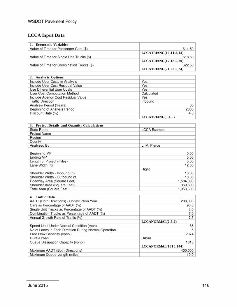
WSDOT Pavement Policy
June 2015
116
LCCA Input Data
1. Economic Variables Value of Time for Passenger Cars ($) $11.50 LCCATRIANG(10,11.5,13) Value of Time for Single Unit Trucks ($) $18.50 LCCATRIANG(17,18.5,20) Value of Time for Combination Trucks ($) $22.50 LCCATRIANG(21,22.5,24)
2. Analysis Options Include User Costs in Analysis Yes Include User Cost Residual Value Yes Use Differential User Costs Yes User Cost Computation Method Calculated Include Agency Cost Residual Value Yes Traffic Direction Inbound Analysis Period (Years) 60 Beginning of Analysis Period 2003 Discount Rate (%) 4.0 LCCATRIANG(3,4,5)
3. Project Details and Quantity Calculations State Route LCCA Example Project Name Region County Analyzed By L. M. Pierce Beginning MP 0.00 Ending MP 5.00 Length of Project (miles) 5.00 Lane Width (ft) 12.00 Right Shoulder Width - Inbound (ft) 10.00 Shoulder Width - Outbound (ft) 10.00 Roadway Area (Square Feet) 1,584,000 Shoulder Area (Square Feet) 369,600 Total Area (Square Feet) 1,953,600
4. Traffic Data AADT (Both Directions) - Construction Year 200,000 Cars as Percentage of AADT (%) 90.0 Single Unit Trucks as Percentage of AADT (%) 3.0 Combination Trucks as Percentage of AADT (%) 7.0 Annual Growth Rate of Traffic (%) 2.5 LCCANORMAL(2.5,2) Speed Limit Under Normal Condition (mph) 65 No of Lanes in Each Direction During Normal Operation 5 Free Flow Capacity (vphpl) 2074 Rural/Urban Urban Queue Dissipation Capacity (vphpl) 1818 LCCANORMAL(1818,144) Maximum AADT (Both Directions) 400,000 Maximum Queue Length (miles) 10.0
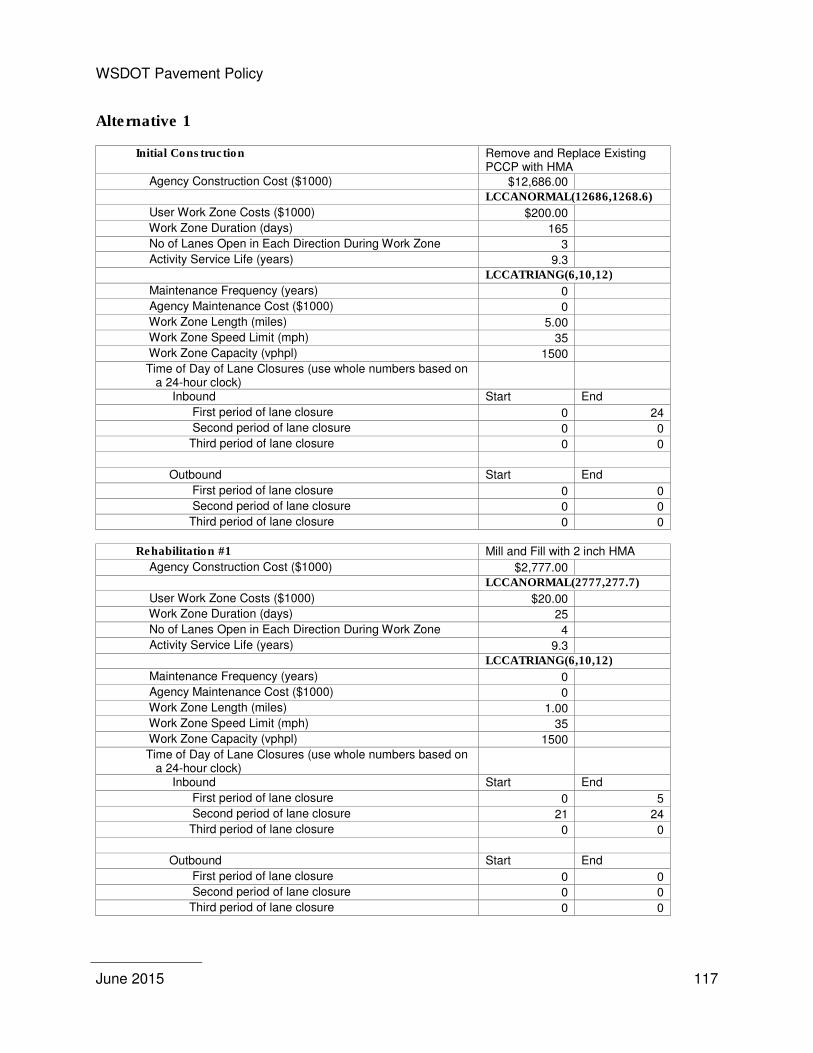
WSDOT Pavement Policy
June 2015
117
Alternative 1
Initial Construction Remove and Replace Existing PCCP with HMA
Agency Construction Cost ($1000) $12,686.00
LCCANORMAL(12686,1268.6)
User Work Zone Costs ($1000) $200.00
Work Zone Duration (days) 165
No of Lanes Open in Each Direction During Work Zone 3
Activity Service Life (years) 9.3
LCCATRIANG(6,10,12)
Maintenance Frequency (years) 0
Agency Maintenance Cost ($1000) 0
Work Zone Length (miles) 5.00
Work Zone Speed Limit (mph) 35
Work Zone Capacity (vphpl) 1500
Time of Day of Lane Closures (use whole numbers based on a 24-hour clock)
Inbound Start End
First period of lane closure 0 24
Second period of lane closure 0 0
Third period of lane closure 0 0
Outbound Start End
First period of lane closure 0 0
Second period of lane closure 0 0
Third period of lane closure 0 0
Rehabilitation #1 Mill and Fill with 2 inch HMA
Agency Construction Cost ($1000) $2,777.00
LCCANORMAL(2777,277.7)
User Work Zone Costs ($1000) $20.00
Work Zone Duration (days) 25
No of Lanes Open in Each Direction During Work Zone 4
Activity Service Life (years) 9.3
LCCATRIANG(6,10,12)
Maintenance Frequency (years) 0
Agency Maintenance Cost ($1000) 0
Work Zone Length (miles) 1.00
Work Zone Speed Limit (mph) 35
Work Zone Capacity (vphpl) 1500
Time of Day of Lane Closures (use whole numbers based on a 24-hour clock)
Inbound Start End
First period of lane closure 0 5
Second period of lane closure 21 24
Third period of lane closure 0 0
Outbound Start End
First period of lane closure 0 0
Second period of lane closure 0 0
Third period of lane closure 0 0

WSDOT Pavement Policy
June 2015
118
Rehabilitation #2 2 inch HMA Overlay
Agency Construction Cost ($1000) $3,409.00
LCCANORMAL(3409,340.9)
User Work Zone Costs ($1000) $30.00
Work Zone Duration (days) 35
No of Lanes Open in Each Direction During Work Zone 4
Activity Service Life (years) 9.3
LCCATRIANG(6,10,12)
Maintenance Frequency (years) 0
Agency Maintenance Cost ($1000) 0
Work Zone Length (miles) 1.00
Work Zone Speed Limit (mph) 35
Work Zone Capacity (vphpl) 1500
Time of Day of Lane Closures (use whole numbers based on a 24-hour clock)
Inbound Start End
First period of lane closure 0 5
Second period of lane closure 21 24
Third period of lane closure 0 0
Outbound Start End
First period of lane closure 0 0
Second period of lane closure 0 0
Third period of lane closure 0 0
Rehabilitation #3 Mill and Fill with 2 inch HMA
Agency Construction Cost ($1000) $2,777.00
LCCANORMAL(2777,277.7)
User Work Zone Costs ($1000) $20.00
Work Zone Duration (days) 25
No of Lanes Open in Each Direction During Work Zone 4
Activity Service Life (years) 9.3
LCCATRIANG(6,10,12)
Maintenance Frequency (years) 0
Agency Maintenance Cost ($1000) 0
Work Zone Length (miles) 1.00
Work Zone Speed Limit (mph) 35
Work Zone Capacity (vphpl) 1500
Time of Day of Lane Closures (use whole numbers based on a 24-hour clock)
Inbound Start End
First period of lane closure 0 5
Second period of lane closure 21 24
Third period of lane closure 0 0
Outbound Start End
First period of lane closure 0 0
Second period of lane closure 0 0
Third period of lane closure 0 0
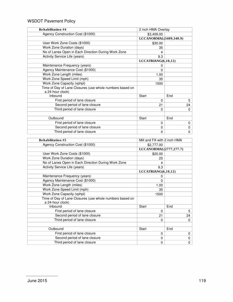
WSDOT Pavement Policy
June 2015
119
Rehabilitation #4 2 inch HMA Overlay
Agency Construction Cost ($1000) $3,409.00
LCCANORMAL(3409,340.9)
User Work Zone Costs ($1000) $30.00
Work Zone Duration (days) 35
No of Lanes Open in Each Direction During Work Zone 4
Activity Service Life (years) 9.3
LCCATRIANG(6,10,12)
Maintenance Frequency (years) 0
Agency Maintenance Cost ($1000) 0
Work Zone Length (miles) 1.00
Work Zone Speed Limit (mph) 35
Work Zone Capacity (vphpl) 1500
Time of Day of Lane Closures (use whole numbers based on a 24-hour clock)
Inbound Start End
First period of lane closure 0 5
Second period of lane closure 21 24
Third period of lane closure 0 0
Outbound Start End
First period of lane closure 0 0
Second period of lane closure 0 0
Third period of lane closure 0 0
Rehabilitation #5 Mill and Fill with 2 inch HMA
Agency Construction Cost ($1000) $2,777.00
LCCANORMAL(2777,277.7)
User Work Zone Costs ($1000) $20.00
Work Zone Duration (days) 25
No of Lanes Open in Each Direction During Work Zone 4
Activity Service Life (years) 9.3
LCCATRIANG(6,10,12)
Maintenance Frequency (years) 0
Agency Maintenance Cost ($1000) 0
Work Zone Length (miles) 1.00
Work Zone Speed Limit (mph) 35
Work Zone Capacity (vphpl) 1500
Time of Day of Lane Closures (use whole numbers based on a 24-hour clock)
Inbound Start End
First period of lane closure 0 5
Second period of lane closure 21 24
Third period of lane closure 0 0
Outbound Start End
First period of lane closure 0 0
Second period of lane closure 0 0
Third period of lane closure 0 0
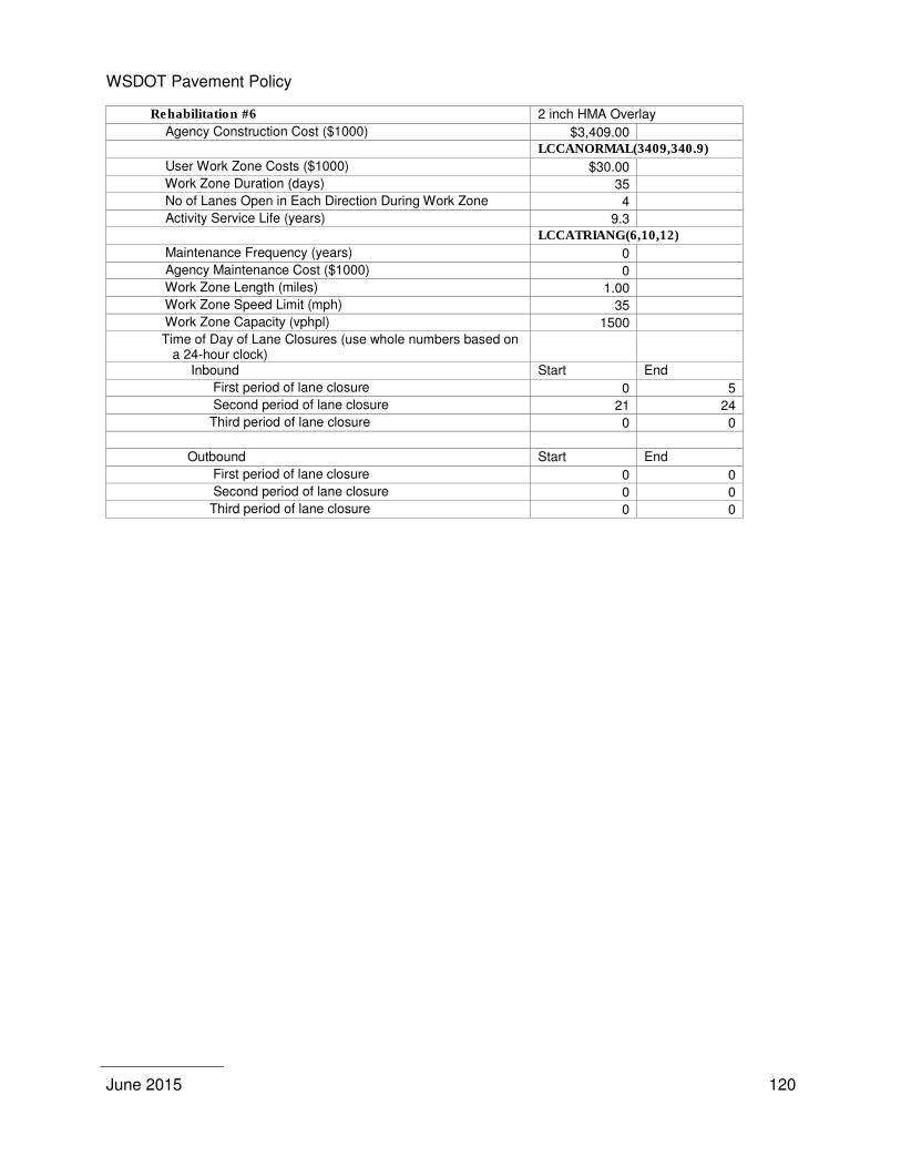
WSDOT Pavement Policy
June 2015
120
Rehabilitation #6 2 inch HMA Overlay
Agency Construction Cost ($1000) $3,409.00
LCCANORMAL(3409,340.9)
User Work Zone Costs ($1000) $30.00
Work Zone Duration (days) 35
No of Lanes Open in Each Direction During Work Zone 4
Activity Service Life (years) 9.3
LCCATRIANG(6,10,12)
Maintenance Frequency (years) 0
Agency Maintenance Cost ($1000) 0
Work Zone Length (miles) 1.00
Work Zone Speed Limit (mph) 35
Work Zone Capacity (vphpl) 1500
Time of Day of Lane Closures (use whole numbers based on a 24-hour clock)
Inbound Start End
First period of lane closure 0 5
Second period of lane closure 21 24
Third period of lane closure 0 0
Outbound Start End
First period of lane closure 0 0
Second period of lane closure 0 0
Third period of lane closure 0 0
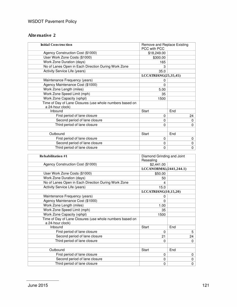
WSDOT Pavement Policy
June 2015
121
Alternative 2
Initial Construction Remove and Replace Existing PCC with PCC
Agency Construction Cost ($1000) $18,249.00
User Work Zone Costs ($1000) $300.00
Work Zone Duration (days) 165
No of Lanes Open in Each Direction During Work Zone 3
Activity Service Life (years) 35.0
LCCATRIANG(25,35,45)
Maintenance Frequency (years) 0
Agency Maintenance Cost ($1000) 0
Work Zone Length (miles) 5.00
Work Zone Speed Limit (mph) 35
Work Zone Capacity (vphpl) 1500
Time of Day of Lane Closures (use whole numbers based on a 24-hour clock)
Inbound Start End
First period of lane closure 0 24
Second period of lane closure 0 0
Third period of lane closure 0 0
Outbound Start End
First period of lane closure 0 0
Second period of lane closure 0 0
Third period of lane closure 0 0
Rehabilitation #1 Diamond Grinding and Joint
Resealing Agency Construction Cost ($1000) $2,441.00
LCCANORMAL(2441,244.1)
User Work Zone Costs ($1000) $50.00
Work Zone Duration (days) 50
No of Lanes Open in Each Direction During Work Zone 4
Activity Service Life (years) 15.0
LCCATRIANG(10,15,20)
Maintenance Frequency (years) 0
Agency Maintenance Cost ($1000) 0
Work Zone Length (miles) 1.00
Work Zone Speed Limit (mph) 35
Work Zone Capacity (vphpl) 1500
Time of Day of Lane Closures (use whole numbers based on a 24-hour clock)
Inbound Start End
First period of lane closure 0 5
Second period of lane closure 21 24
Third period of lane closure 0 0
Outbound Start End
First period of lane closure 0 0
Second period of lane closure 0 0
Third period of lane closure 0 0
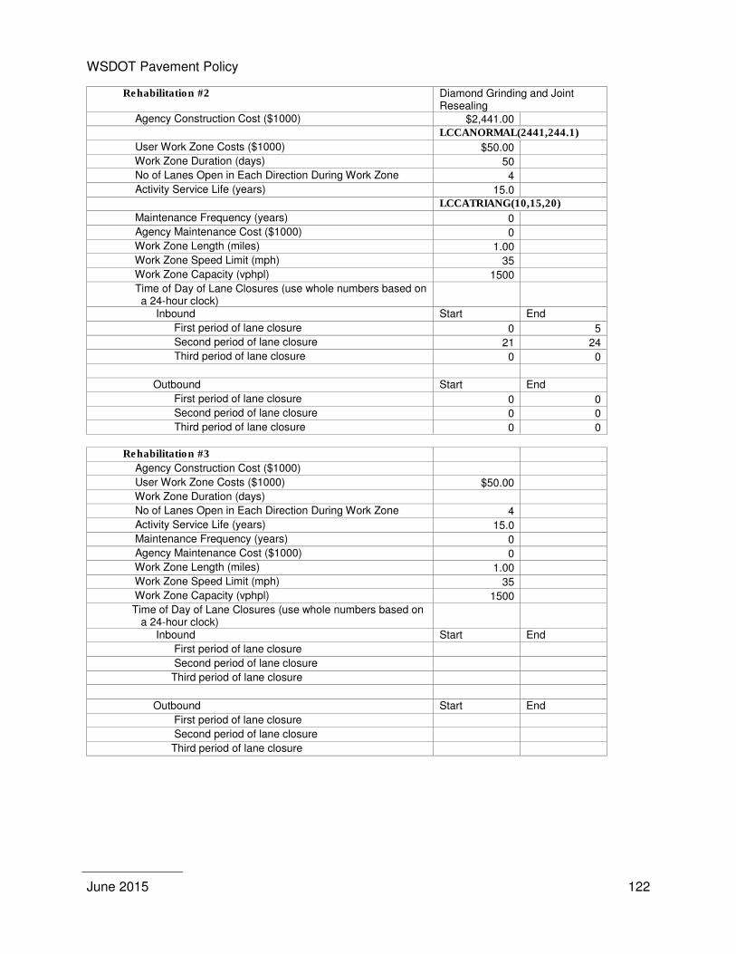
WSDOT Pavement Policy
June 2015
122
Rehabilitation #2 Diamond Grinding and Joint Resealing
Agency Construction Cost ($1000) $2,441.00
LCCANORMAL(2441,244.1)
User Work Zone Costs ($1000) $50.00
Work Zone Duration (days) 50
No of Lanes Open in Each Direction During Work Zone 4
Activity Service Life (years) 15.0
LCCATRIANG(10,15,20)
Maintenance Frequency (years) 0
Agency Maintenance Cost ($1000) 0
Work Zone Length (miles) 1.00
Work Zone Speed Limit (mph) 35
Work Zone Capacity (vphpl) 1500
Time of Day of Lane Closures (use whole numbers based on a 24-hour clock)
Inbound Start End
First period of lane closure 0 5
Second period of lane closure 21 24
Third period of lane closure 0 0
Outbound Start End
First period of lane closure 0 0
Second period of lane closure 0 0
Third period of lane closure 0 0
Rehabilitation #3
Agency Construction Cost ($1000)
User Work Zone Costs ($1000) $50.00
Work Zone Duration (days)
No of Lanes Open in Each Direction During Work Zone 4
Activity Service Life (years) 15.0
Maintenance Frequency (years) 0
Agency Maintenance Cost ($1000) 0
Work Zone Length (miles) 1.00
Work Zone Speed Limit (mph) 35
Work Zone Capacity (vphpl) 1500
Time of Day of Lane Closures (use whole numbers based on a 24-hour clock)
Inbound Start End
First period of lane closure
Second period of lane closure
Third period of lane closure
Outbound Start End
First period of lane closure
Second period of lane closure
Third period of lane closure
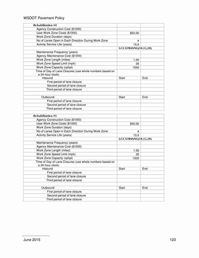
WSDOT Pavement Policy
June 2015
123
Rehabilitation #4
Agency Construction Cost ($1000)
User Work Zone Costs ($1000) $50.00
Work Zone Duration (days)
No of Lanes Open in Each Direction During Work Zone 4
Activity Service Life (years) 15.0
LCCATRIANG(10,15,20)
Maintenance Frequency (years)
Agency Maintenance Cost ($1000)
Work Zone Length (miles) 1.00
Work Zone Speed Limit (mph) 35
Work Zone Capacity (vphpl) 1500
Time of Day of Lane Closures (use whole numbers based on a 24-hour clock)
Inbound Start End
First period of lane closure
Second period of lane closure
Third period of lane closure
Outbound Start End
First period of lane closure
Second period of lane closure
Third period of lane closure
Rehabilitation #5
Agency Construction Cost ($1000)
User Work Zone Costs ($1000) $50.00
Work Zone Duration (days)
No of Lanes Open in Each Direction During Work Zone 4
Activity Service Life (years) 15.0
LCCATRIANG(10,15,20)
Maintenance Frequency (years)
Agency Maintenance Cost ($1000)
Work Zone Length (miles) 1.00
Work Zone Speed Limit (mph) 35
Work Zone Capacity (vphpl) 1500
Time of Day of Lane Closures (use whole numbers based on a 24-hour clock)
Inbound Start End
First period of lane closure
Second period of lane closure
Third period of lane closure
Outbound Start End
First period of lane closure
Second period of lane closure
Third period of lane closure
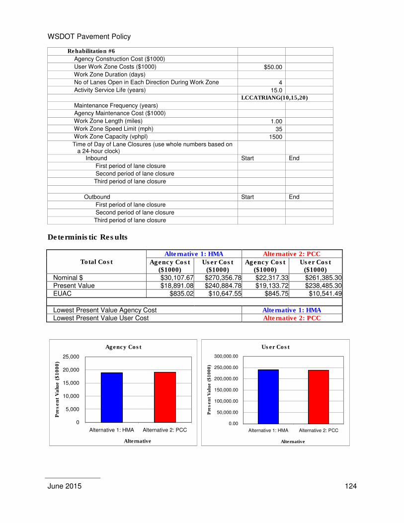
WSDOT Pavement Policy
June 2015
124
Rehabilitation #6
Agency Construction Cost ($1000)
User Work Zone Costs ($1000) $50.00
Work Zone Duration (days)
No of Lanes Open in Each Direction During Work Zone 4
Activity Service Life (years) 15.0
LCCATRIANG(10,15,20)
Maintenance Frequency (years)
Agency Maintenance Cost ($1000)
Work Zone Length (miles) 1.00
Work Zone Speed Limit (mph) 35
Work Zone Capacity (vphpl) 1500
Time of Day of Lane Closures (use whole numbers based on a 24-hour clock)
Inbound Start End
First period of lane closure
Second period of lane closure
Third period of lane closure
Outbound Start End
First period of lane closure
Second period of lane closure
Third period of lane closure
Deterministic Results
Total Cost Alternative 1: HMA Alternative 2: PCC
Agency Cost ($1000)
User Cost ($1000)
Agency Cost ($1000)
User Cost ($1000)
Nominal $ $30,107.67 $270,356.78 $22,317.33 $261,385.30 Present Value $18,891.08 $240,884.78 $19,133.72 $238,485.30 EUAC $835.02 $10,647.55 $845.75 $10,541.49
Lowest Present Value Agency Cost Alternative 1: HMA Lowest Present Value User Cost Alternative 2: PCC
Agency Cost
0
5,000
10,000
15,000
20,000
25,000
Alternative 1: HMA Alternative 2: PCC
Alternative
Pre
se
nt
Va
lue
($
10
00
)
User Cost
0.00
50,000.00
100,000.00
150,000.00
200,000.00
250,000.00
300,000.00
Alternative 1: HMA Alternative 2: PCC
Alternative
Pre
se
nt
Va
lue
($
10
00
)
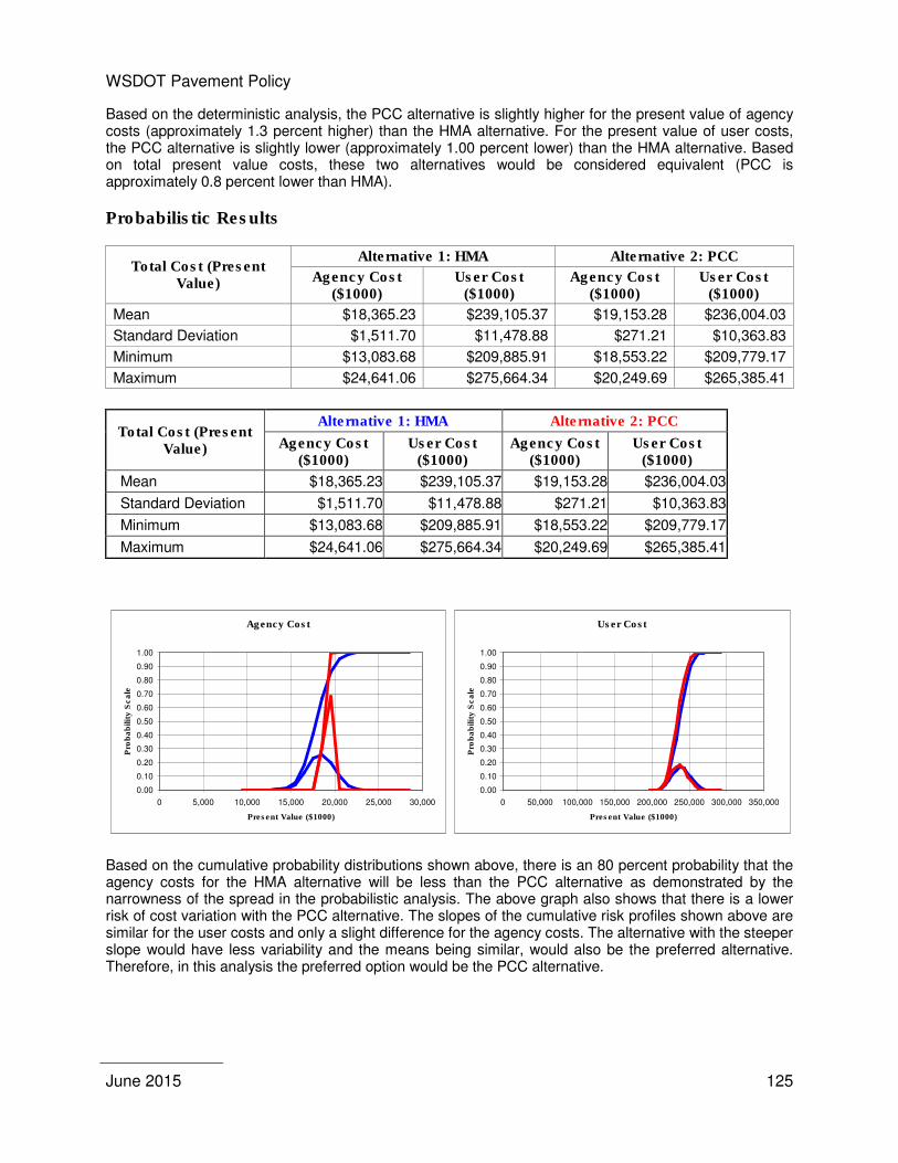
WSDOT Pavement Policy
June 2015
125
Based on the deterministic analysis, the PCC alternative is slightly higher for the present value of agency costs (approximately 1.3 percent higher) than the HMA alternative. For the present value of user costs, the PCC alternative is slightly lower (approximately 1.00 percent lower) than the HMA alternative. Based on total present value costs, these two alternatives would be considered equivalent (PCC is approximately 0.8 percent lower than HMA).
Probabilistic Results
Total Cost (Present Value)
Alternative 1: HMA Alternative 2: PCC
Agency Cost ($1000)
User Cost ($1000)
Agency Cost ($1000)
User Cost ($1000)
Mean $18,365.23 $239,105.37 $19,153.28 $236,004.03
Standard Deviation $1,511.70 $11,478.88 $271.21 $10,363.83
Minimum $13,083.68 $209,885.91 $18,553.22 $209,779.17
Maximum $24,641.06 $275,664.34 $20,249.69 $265,385.41
Based on the cumulative probability distributions shown above, there is an 80 percent probability that the agency costs for the HMA alternative will be less than the PCC alternative as demonstrated by the narrowness of the spread in the probabilistic analysis. The above graph also shows that there is a lower risk of cost variation with the PCC alternative. The slopes of the cumulative risk profiles shown above are similar for the user costs and only a slight difference for the agency costs. The alternative with the steeper slope would have less variability and the means being similar, would also be the preferred alternative. Therefore, in this analysis the preferred option would be the PCC alternative.
Agency Cost
0.00
0.10
0.20
0.30
0.40
0.50
0.60
0.70
0.80
0.90
1.00
0 5,000 10,000 15,000 20,000 25,000 30,000
Present Value ($1000)
Pro
ba
bilit
y S
ca
le
User Cost
0.00
0.10
0.20
0.30
0.40
0.50
0.60
0.70
0.80
0.90
1.00
0 50,000 100,000 150,000 200,000 250,000 300,000 350,000
Present Value ($1000)
Pro
ba
bilit
y S
ca
le

WSDOT Pavement Policy
June 2015
126

WSDOT Pavement Policy
June 2015
127
APPENDIX 7 – PROJECT SPECIFIC DETAILS
The following are examples of project specific details that may be considered:
� Air pollution impacts. Consider if either effects on traffic or effects during production affect the project or future preservation efforts
� Non-user impacts. How are surrounding neighborhoods affected by the project? How do these impacts vary depending on the type of pavement selected? What are the impacts at the point of production?
� Haul routes through neighborhoods. Consider the impacts both during initial construction and future preservation projects.
� Future ability of plants to operate at night in urban areas and associated cost increases. Where are typical production plants located? Will night work continue to be feasible in the area of plant production or will urban growth affect this? What possible effect will urban growth have on making production plants move further away from the corridor?
� Neighborhood impacts due to trip diversion during preservation projects. When a highway closure impacts the traveling public, many will divert to other routes to avoid delays. These diversions have associated costs, in and of themselves. Some of the costs come from backups and delays (user impacts) on these diversion routes; some of the costs come from impacts to neighborhoods, through increased traffic, noise, congestion, air pollution, safety and accident risks. Consider the level of user delays and the likelihood that diversions will occur and the level of impact these diversions could have on non-highway users.
� Business impacts due to reduced or restricted access. This impact happens both due to direct impacts to users and to impacts due to diversion. The magnitude grows as an area urbanizes and increases the number of businesses that stay open for extended (mostly nighttime) hours of operation. Diversion through a neighborhood with extensive commercial business can greatly impact those businesses.
� Effect of nighttime noise variances and risk of approval of noise variances. These two items tie in with the item noted above. As urban areas grow, nighttime noise variances become more difficult to obtain and more restrictive in their limitations. Review the corridor in question and the expected growth projections, to develop an idea of the risk associated with this non-user impact. Noise restrictions can limit hours of operations to the point of preventing work, or they can restrict noise levels below that achievable by state of the practice construction equipment. Noise restrictions apply also to vibration and noise generated by vibratory equipment and these restrictions can prevent the use of particular equipment within selected urban corridors. A single resident affected by nighttime noise can and has effectively shut down projects, forcing a move to day work and created huge impacts on highway users through delay and impacts.
� Noise − Noise walls. Evaluate whether the corridor already has noise walls or is expected to have noise
walls by the time of the project, and the impacts having or not having the walls might have on non-users/residents, both for construction noise and pavement noise
− Haul through neighborhoods at night. Haul though neighborhoods at night (and if you are hauling, you are traveling through someone’s neighborhood) should be considered as an impact. Sparsely
WSDOT Pavement Policy
June 2015
128
populated areas will obviously have a smaller impact due to the noise of hauling vehicles than densely packed urban areas.
− Noise from diverted traffic and other impacts. Diverted traffic must drive through someone’s neighborhood to get to where they are going. At night, diverted traffic, especially involving large trucks, can have a significant noise impact on neighborhoods.
− Noise generation during preservation projects. When preservation projects are performed on any pavement, noise is generated and its impacts on the local community must also be considered, in addition to the impact of the noise from the initial construction.
� Safety. − Public exposure to traffic control during lane closures. − Work exposure to traffic during lane closures. − Lane closures are a safety risk factor for both workers and the traveling public. Limited vision,
nighttime lighting, temporary traffic control and other factors increase the risk of accidents to both motorists and to workers within the work zone. Evaluate the risk to both, given the nature of the corridor, the ADT, the degree of urbanization and the complexity of the facility.
− Safety risks associated with maintenance by state forces between preservation projects.
� Pavement type continuity within a corridor (similar to architectural choices for structures and wall-types within a corridor and landscape architectural choices for continuity within a corridor). It is generally not desirable to switch pavement types over relatively short stretches of highway. Maintenance needs change for each given pavement type, as do preservation needs. Further, the change in pavement type impacts the public in various ways, including aesthetics.
� Environmental effects. − Runoff temperature due to heating effects depending on pavement type. Evaluate in conjunction
with design of the storm sewer system.

WSDOT Pavement Policy
June 2015
129
APPENDIX 8 – WSDOT PAVEMENT TYPE SELECTION COMMITTEE AND SAMPLE MEMORANDUM
The Pavement-Type Selection Committee is composed of:
1. Chief Engineer, Assistant Secretary of Engineering and Regional Operations 2. State Construction Engineer 3. State Design Engineer 4. Director Capital Program Development and Management 5. Regional Administrator of the Region in which the project under consideration is located
WSDOT Pavement Policy
June 2015
130
April 16, 2009 TO: L. Laird, 47315 FROM: Jeff Carpenter, 47365 State Construction Engineer SUBJECT: Pavement Type Selection Process
When the pavement type selection has been completed and forwarded to the State Materials Laboratory Pavement Division will formulate the Pavement Type Selection Committee (referred to as the Committee) Approval Letter and request that each member of the Committee sign and forward the letter on to the next member. The Committee is not required to convene if the life cycle cost analysis between the alternatives is greater than 15 percent and the recommendations are acceptable to both the Region and the State Materials Laboratory Pavements Division. The Approval Letter shall provide the necessary documentation that supports the Committee’s selection of the pavement type.
Projects to be reviewed shall be distributed to the Committee members for approval (see attached example of Approval Letter). Based on this review and obtaining consensus from the Committee, the Pavement Division will either process the Approval Letter, take appropriate action to obtain consensus, or convene the Committee.
In order to expedite the required time and expended level of effort for the review of pavement type selection projects, the following procedure is recommended:
1. The Committee should convene if the pavement type recommended by the Region is contrary to pavement design and project specific detail recommendations. The pavement design and project specific detail recommendations shall be subject to the review of the Pavement Division or any member of the Committee. Under these circumstances it shall be the responsibility of the Pavements Division or the Committee member to formulate, in writing, why the selected pavement type is not appropriate and distribute his/her rationale to all members. If all members agree with the recommendations a meeting will not be necessary, otherwise, the Committee should convene.
2. The Committee should convene at the request of any member.
TEB: jsu

WSDOT Pavement Policy
June 2015
131
PAVEMENT TYPE SELECTION
SR-3 Luoto Road to SR-305 MP 48.90 to MP 53.00
The Pavement Type Selection Committee has completed its review of the pavement type selection for the project SR-3 Luoto Road to SR-305, MP 48.90 to MP 53.00.
The project consists of constructing the final two lanes of the ultimate four-lane facility from Luoto Road to SR-305.
The pavement design analysis resulted in both pavement types (HMA and PCC) being viable. In the life cycle cost analysis, one PCC alternative was compared to one HMA alternative. In the life cycle cost analysis of the two alternatives, there is a cost advantage in the use of HMA over PCC of greater than 15 percent. The Committee approves the use of HMA on this project.
The Pavement Type Selection Committee
______________________________ _________________________________ Chief Engineer State Design Engineer Assistant Secretary of Engineering and Regional Operations
______________________________ _________________________________ State Construction Engineer Director Capital Program Development and Management
______________________________ Olympic Region Administrator
JU:ck