Embed Size (px)
Citation preview
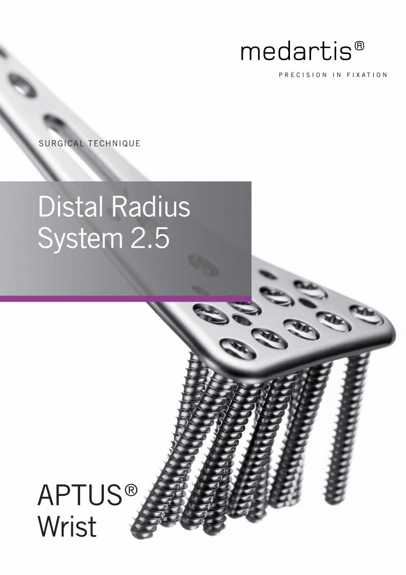
Distal Radius System 2.5
APTUS®
Wrist
SURGICAL TECHNIQUE
Distal Radius System 2.5
LITERATURE
1. Krimmer, H., Pessenlehner, C., Haßelbacher, K., Meier, M., Roth, F., and Meier, R. Palmar fi xed angle plating systems for instable distal radius fractures [Palmare winkelstabile Plattenosteosynthese der instabilen distalen Radiusfraktur] Unfallchirurg, 107[6], 460-467. 2004.
2. Mehling, I., Meier, M., Schloer, U., and Krimmer, H. Multidirectional Palmar Fixed-Angle Plate Fixation for Unstable Distal Radius Fracture [Multidirektionale winkelstabile Versorgung der instabilen distalen Radiusfraktur] Handchir.Mikrochir.Plast.Chir, 39[1], 29-33. 2007.
3. Moser, V. L., Pessenlehner, C., Meier, M., and Krimmer, H. Anterior Fixed Angle Plate Fixation of Unstable Distal Radius Fractures [Palmare winkelstabile Plattenosteosynthese der instabilen distalen Radiusfraktur] Operat.Orthop.Traumatol., 16[4], 380-396. 2004.
4. Jakubietz, R. G., Gruenert, J. G., Kloss, D. F., Schindele, S., and Jakubietz, M. G. A Randomised Clinical Study Comparing Palmar and Dorsal Fixed-Angle Plates for the Internal Fixation of AO C-Type Fractures of the Distal Radius in the Elderly Journal of Hand Surgery, European Volume 33[5], 600-604. 2008.
5. Figl, M., Weninger, P., Liska, M., Hofbauer, M., and Leixnering, M. Volar fi xed-angle plate osteosynthesis of unstable distal radius fractures: 12 months results Arch.Orthop.Trauma Surg., 129[5], 661-669. 2009.
6. Weninger, P., Schueller, M., Drobetz, H., Jamek, M., Redl, H., and Tschegg, E. Infl uence of an Additional Locking Screw on Fracture Reduction After Volar Fixed-Angle Plating – Introduction of the “Protection Screw” in an Extra-Articular Distal Radius Fracture Model Journal of Trauma - Injury, Infection, and Critical Care, 67[4], 746-751. 2009.
7. Figl, M., Weninger, P., Jurkowitsch, J., Hofbauer, M., Schauer, J., and Leixnering, M. Unstable Distal Radius Fractures in the Elderly Patient – Volar Fixed-Angle Plate Osteosynthesis Prevents Secondary Loss of Reduction Journal of Trauma - Injury, Infection, and Critical Care, 68[4], 992-998. 2010.
8. Sonderegger, J., Schindele, S., Rau, M., and Gruenert, J. G. Palmar multidirectional fi xed-angle plate fi xation in distal radius fractures: do intraarticular fractures have a worse outcome than extraarticular fractures? Arch.Orthop.Trauma Surg., 2010.
9. Richter, R., Konnl, E., and Krimmer, H. Strategy of early corrective osteotomy [Strategie der Radiusfrühkorrektur] Obere Extremität, 5[2], 92-97. 2010.
10. Haefeli, M., Stober, R., Plaass, C., Jenzer, A., and Steiger, R. First experience with a dorsal plate in modern design for the treatment of distal radius fractures Journal of Hand Surgery, European Volume 35E[S1], A-0461. 2010.
CONTENTS
2 Literature
4 Introduction
5 Surgical Principles and Objectives
5 Advantages
5 Indications
5 Contraindications
5 Patient Information
5 Pre-Operative Work-Up
5 Surgical Instruments
5 Anesthesia and Positioning
5 Postoperative Management
6 Removal of Implants
6 Errors, Hazards, Possible Complications
8 – 11 Surgical Technique I –
according to Prof. Dr. Hermann Krimmer, Ravensburg, Germany
12 – 17 Surgical Technique II –
according to Dr. Christoph Ranft, Kiel, Germany
18 – 19 Correct Application of the TriLock Locking Technology
Distal Radius System 2.5
Medartis, APTUS, MODUS, TriLock, HexaDrive and SpeedTip are registered trademarks of Medartis AG, 4057 Basel, Switzerland
4 | Distal Radius System 2.5
www.medartis.com/products/aptus/wrist
At a GlanceDistal Radius System 2.5
INTRODUCTION
In recent years, the distal radius fracture, first described
by Colles in 1814, has undergone great changes in the
approach to its treatment. By using a conservative
treatment in a cast or by trying to stabilize the fracture
with minimally invasive Kirschner wires, the reduction result
of the comminuted fracture is often not or only temporarily
maintained. Even the sole external fixation after reduction
by ligamentotaxis often does not lead to a permanent
maintenance of reduction.
A combination of both methods may prevent a slow
impaction, but requires the wires to be left in place
for approximately another 6 weeks after the removal
of the fixator until bone healing has been accomplished.
The advantage of a volar approach lies in an improved
soft tissue coverage, less danger of irritation to the
tendons, and better control of reduction of the cortex,
in most instances only fractured volarly.
In acute fractures, especially those with multiple fragments
and dorsal comminution, screw loosening with secondary
loss of correction constituted a major problem. This was
caused by the lack of stable bicortical screw purchase, as
the screws did not find a proper anchorage in the dorsal
comminution. Therefore, an additional cancellous bone graft
or the use of a bone substitute inserted dorsally was
necessary.
Currently, patients have increased demands and socioeco-
nomic factors have become more relevant: an anatomic
reconstruction and a permanent reduction have been
targeted together with a postoperative immobilization of
short duration and early rehabilitation.
Based on the principle of fixed angle devices, new methods
of osteosynthesis have been developed. They function like an
internal fixator, markedly reduce the mentioned complica-
tions, almost always exclude the need for bone grafting and
are not limited by a fixed time frame as required by an
external fixator.
The volar approach allows an exact reduction and the fixed
angle device a permanent maintenance of reduction without
the need for additional bone grafts. The postoperative
complications, particularly of malunion necessitating
a revision, are markedly reduced. The anatomic reduction
of distal radius fractures is also indicated in patients of
advanced age.
Distal Radius System 2.5 | 5
www.medartis.com/products/aptus/wrist
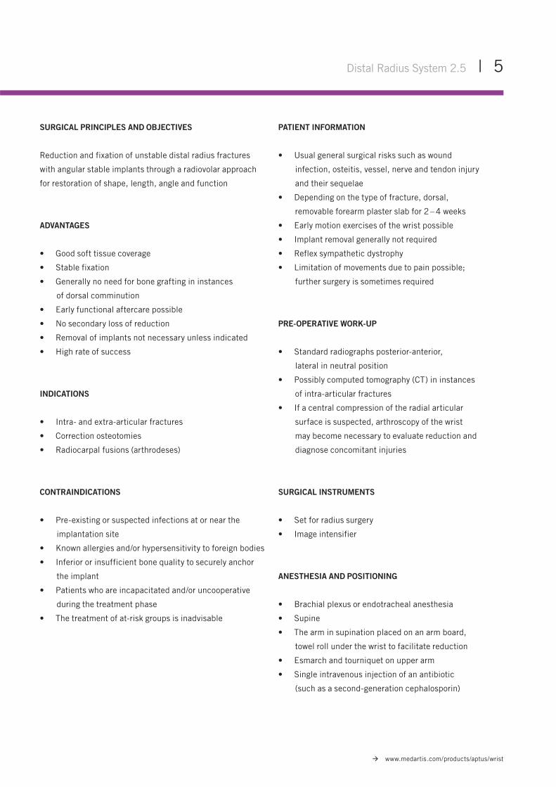
SURGICAL PRINCIPLES AND OBJECTIVES
Reduction and fixation of unstable distal radius fractures
with angular stable implants through a radiovolar approach
for restoration of shape, length, angle and function
ADVANTAGES
• Good soft tissue coverage
• Stable fixation
• Generally no need for bone grafting in instances
of dorsal comminution
• Early functional aftercare possible
• No secondary loss of reduction
• Removal of implants not necessary unless indicated
• High rate of success
INDICATIONS
• Intra- and extra-articular fractures
• Correction osteotomies
• Radiocarpal fusions (arthrodeses)
CONTRAINDICATIONS
• Pre-existing or suspected infections at or near the
implantation site
• Known allergies and/or hypersensitivity to foreign bodies
• Inferior or insufficient bone quality to securely anchor
the implant
• Patients who are incapacitated and/or uncooperative
during the treatment phase
• The treatment of at-risk groups is inadvisable
PATIENT INFORMATION
• Usual general surgical risks such as wound
infection, osteitis, vessel, nerve and tendon injury
and their sequelae
• Depending on the type of fracture, dorsal,
removable forearm plaster slab for 2 – 4 weeks
• Early motion exercises of the wrist possible
• Implant removal generally not required
• Reflex sympathetic dystrophy
• Limitation of movements due to pain possible;
further surgery is sometimes required
PRE-OPERATIVE WORK-UP
• Standard radiographs posterior-anterior,
lateral in neutral position
• Possibly computed tomography (CT) in instances
of intra-articular fractures
• If a central compression of the radial articular
surface is suspected, arthroscopy of the wrist
may become necessary to evaluate reduction and
diagnose concomitant injuries
SURGICAL INSTRUMENTS
• Set for radius surgery
• Image intensifier
ANESTHESIA AND POSITIONING
• Brachial plexus or endotracheal anesthesia
• Supine
• The arm in supination placed on an arm board,
towel roll under the wrist to facilitate reduction
• Esmarch and tourniquet on upper arm
• Single intravenous injection of an antibiotic
(such as a second-generation cephalosporin)
6 | Distal Radius System 2.5
www.medartis.com/products/aptus/wrist
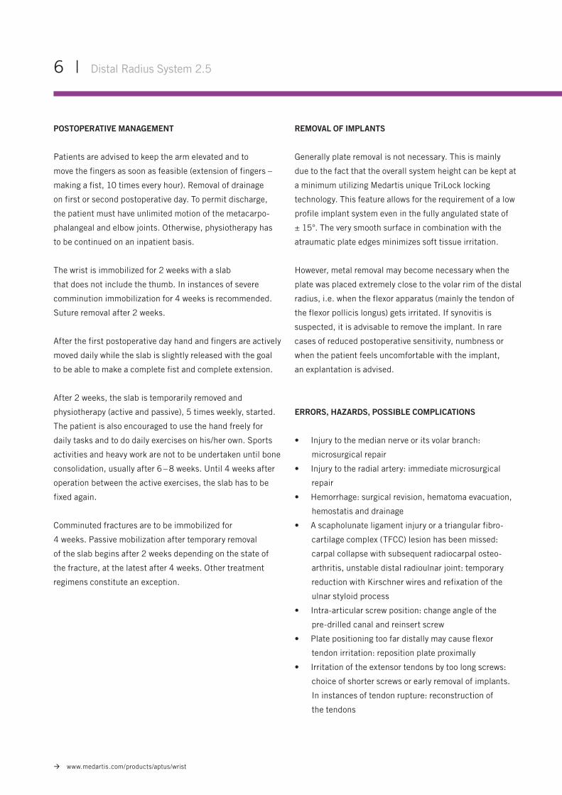
POSTOPERATIVE MANAGEMENT
Patients are advised to keep the arm elevated and to
move the fingers as soon as feasible (extension of fingers –
making a fist, 10 times every hour). Removal of drainage
on first or second postoperative day. To permit discharge,
the patient must have unlimited motion of the metacarpo-
phalangeal and elbow joints. Otherwise, physiotherapy has
to be continued on an inpatient basis.
The wrist is immobilized for 2 weeks with a slab
that does not include the thumb. In instances of severe
comminution immobilization for 4 weeks is recommended.
Suture removal after 2 weeks.
After the first postoperative day hand and fingers are actively
moved daily while the slab is slightly released with the goal
to be able to make a complete fist and complete extension.
After 2 weeks, the slab is temporarily removed and
physiotherapy (active and passive), 5 times weekly, started.
The patient is also encouraged to use the hand freely for
daily tasks and to do daily exercises on his/her own. Sports
activities and heavy work are not to be undertaken until bone
consolidation, usually after 6 – 8 weeks. Until 4 weeks after
operation between the active exercises, the slab has to be
fixed again.
Comminuted fractures are to be immobilized for
4 weeks. Passive mobilization after temporary removal
of the slab begins after 2 weeks depending on the state of
the fracture, at the latest after 4 weeks. Other treatment
regimens constitute an exception.
REMOVAL OF IMPLANTS
Generally plate removal is not necessary. This is mainly
due to the fact that the overall system height can be kept at
a minimum utilizing Medartis unique TriLock locking
technology. This feature allows for the requirement of a low
profile implant system even in the fully angulated state of
± 15°. The very smooth surface in combination with the
atraumatic plate edges minimizes soft tissue irritation.
However, metal removal may become necessary when the
plate was placed extremely close to the volar rim of the distal
radius, i.e. when the flexor apparatus (mainly the tendon of
the flexor pollicis longus) gets irritated. If synovitis is
suspected, it is advisable to remove the implant. In rare
cases of reduced postoperative sensitivity, numbness or
when the patient feels uncomfortable with the implant,
an explantation is advised.
ERRORS, HAZARDS, POSSIBLE COMPLICATIONS
• Injury to the median nerve or its volar branch:
microsurgical repair
• Injury to the radial artery: immediate microsurgical
repair
• Hemorrhage: surgical revision, hematoma evacuation,
hemostatis and drainage
• A scapholunate ligament injury or a triangular fibro-
cartilage complex (TFCC) lesion has been missed:
carpal collapse with subsequent radiocarpal osteo-
arthritis, unstable distal radioulnar joint: temporary
reduction with Kirschner wires and refixation of the
ulnar styloid process
• Intra-articular screw position: change angle of the
pre-drilled canal and reinsert screw
• Plate positioning too far distally may cause flexor
tendon irritation: reposition plate proximally
• Irritation of the extensor tendons by too long screws:
choice of shorter screws or early removal of implants.
In instances of tendon rupture: reconstruction of
the tendons
Distal Radius System 2.5 | 7
www.medartis.com/products/aptus/wrist
• Threat of carpal tunnel syndrome: open carpal canal
• Postoperative swelling and pain: decrease by
consequent elevation of the arm, administration of
non steroidal anti-inflammatory medication, immediate
active movement of the fingers to reduce the edema
• Infections are rarely seen; the risk is increased
in open fractures or in patients with suppressed
immune system. Infections are treated according
to established methods
• Reflex sympathetic dystrophy: generally avoidable
by controlled and early careful mobilization.
If occurring, medical treatment with analgesics,
stellate block and physical and occupational therapy,
preferably on an inpatient basis. In late stage:
surgical arthrolysis
• Even if an optimal reduction has been achieved, a deficit
in motion is often present, especially after comminuted
intra-articular fractures
• Inadequate reduction of the fragments resulting in
malunion: painful limitation of motion and early
development of osteoarthritis. Especially after type C
fractures revision surgery with denervation of the wrist,
partial radioscapholunar arthrodesis or as a salvage
operation: hemiresection of the ulnar head according
to Bowers or an ulnar shortening according to Kapandji-
Sauve
8 | Distal Radius System 2.5
www.medartis.com/products/aptus/wrist
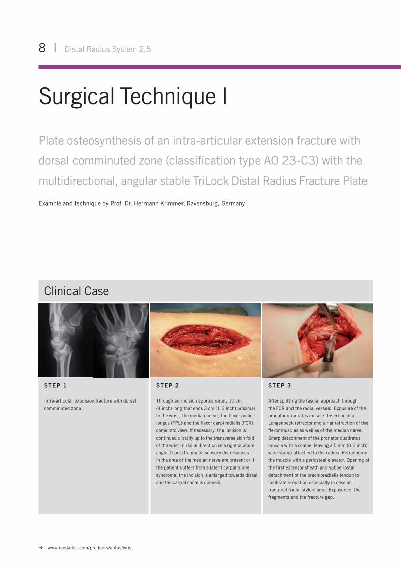
Surgical Technique I
Plate osteosynthesis of an intra-articular extension fracture with
dorsal comminuted zone (classification type AO 23-C3) with the
multidirectional, angular stable TriLock Distal Radius Fracture Plate
Example and technique by Prof. Dr. Hermann Krimmer, Ravensburg, Germany
STEP 1
Intra-articular extension fracture with dorsal
comminuted zone.
STEP 2
Through an incision approximately 10 cm
(4 inch) long that ends 3 cm (1.2 inch) proximal
to the wrist, the median nerve, the flexor pollicis
longus (FPL) and the flexor carpi radialis (FCR)
come into view. If necessary, the incision is
continued distally up to the transverse skin fold
of the wrist in radial direction in a right or acute
angle. If posttraumatic sensory disturbances
in the area of the median nerve are present or if
the patient suffers from a latent carpal tunnel
syndrome, the incision is enlarged towards distal
and the carpal canal is opened.
STEP 3
After splitting the fascia, approach through
the FCR and the radial vessels. Exposure of the
pronator quadratus muscle. Insertion of a
Langenbeck retractor and ulnar retraction of the
flexor muscles as well as of the median nerve.
Sharp detachment of the pronator quadratus
muscle with a scalpel leaving a 5 mm (0.2 inch)
wide stump attached to the radius. Retraction of
the muscle with a periosteal elevator. Opening of
the first extensor sheath and subperiostal
detachment of the brachioradialis tendon to
facilitate reduction especially in case of
fractured radial styloid area. Exposure of the
fragments and the fracture gap.
Clinical Case
Distal Radius System 2.5 | 9
www.medartis.com/products/aptus/wrist
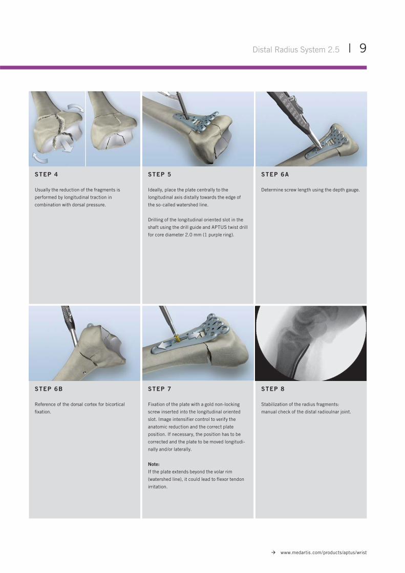
STEP 4
Usually the reduction of the fragments is
performed by longitudinal traction in
combination with dorsal pressure.
STEP 6B
Reference of the dorsal cortex for bicortical
fi xation.
STEP 5
Ideally, place the plate centrally to the
longitudinal axis distally towards the edge of
the so-called watershed line.
Drilling of the longitudinal oriented slot in the
shaft using the drill guide and APTUS twist drill
for core diameter 2.0 mm (1 purple ring).
STEP 7
Fixation of the plate with a gold non-locking
screw inserted into the longitudinal oriented
slot. Image intensifier control to verify the
anatomic reduction and the correct plate
position. If necessary, the position has to be
corrected and the plate to be moved longitudi-
nally and/or laterally.
Note:
If the plate extends beyond the volar rim
(watershed line), it could lead to flexor tendon
irritation.
STEP 6A
Determine screw length using the depth gauge.
STEP 8
Stabilization of the radius fragments:
manual check of the distal radioulnar joint.
10 | Distal Radius System 2.5
www.medartis.com/products/aptus/wrist
* For detailed information about the correct use of TriLock locking technology, see pages 18-19.
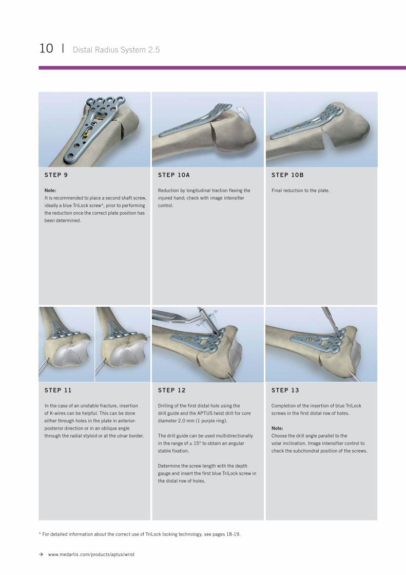
STEP 9
Note:
It is recommended to place a second shaft screw,
ideally a blue TriLock screw*, prior to performing
the reduction once the correct plate position has
been determined.
STEP 11
In the case of an unstable fracture, insertion
of K-wires can be helpful. This can be done
either through holes in the plate in anterior-
posterior direction or in an oblique angle
through the radial styloid or at the ulnar border.
STEP 10A
Reduction by longitudinal traction fl exing the
injured hand; check with image intensifi er
control.
STEP 12
Drilling of the first distal hole using the
drill guide and the APTUS twist drill for core
diameter 2.0 mm (1 purple ring).
The drill guide can be used multidirectionally
in the range of ± 15° to obtain an angular
stable fixation.
Determine the screw length with the depth
gauge and insert the first blue TriLock screw in
the distal row of holes.
STEP 10B
Final reduction to the plate.
STEP 13
Completion of the insertion of blue TriLock
screws in the first distal row of holes.
Note:
Choose the drill angle parallel to the
volar inclination. Image intensifier control to
check the subchondral position of the screws.
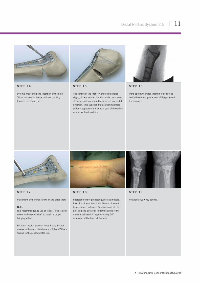
STEP 18
Reattachment of pronator quadratus muscle.
Insertion of a suction drain. Wound closure to
be performed in layers. Application of sterile
dressing and posterior forearm slab up to the
metacarpal heads in approximately 20°
extension of the hand at the wrist.
Distal Radius System 2.5 | 11
www.medartis.com/products/aptus/wrist
STEP 14
Drilling, measuring and insertion of the blue
TriLock screws in the second row pointing
towards the dorsal rim.
STEP 17
Placement of the fi nal screws in the plate shaft.
Note:
It is recommended to use at least 1 blue TriLock
screw in the radius shaft to obtain a proper
bridging effect.
For ideal results, place at least 3 blue TriLock
screws in the most distal row and 2 blue TriLock
screws in the second distal row.
STEP 15
The screws of the first row should be angled
slightly in a proximal direction while the screws
of the second row should be inserted in a distal
direction. This subchondral positioning offers
an ideal support of the central part of the radius
as well as the dorsal rim.
STEP 16
Intra-operative image intensifier control to
verify the correct placement of the plate and
the screws.
STEP 19
Postoperative X-ray control.
12 | Distal Radius System 2.5
www.medartis.com/products/aptus/wrist
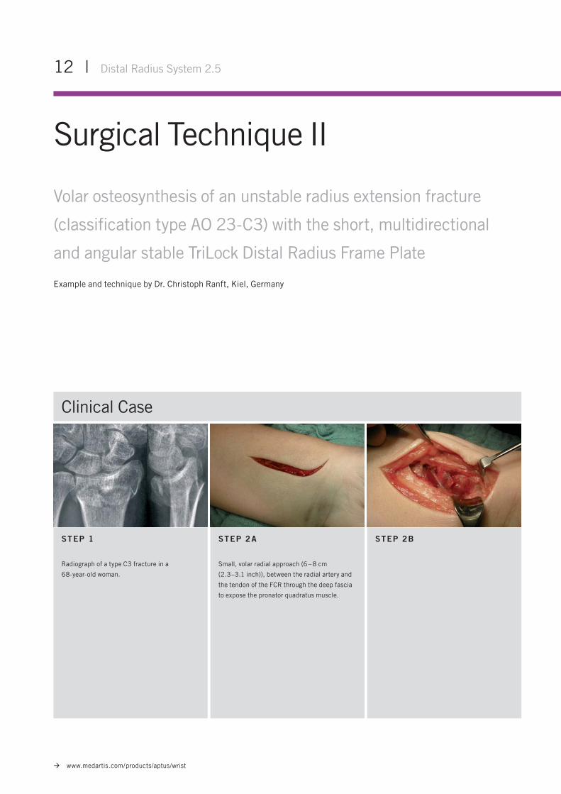
Surgical Technique II
Volar osteosynthesis of an unstable radius extension fracture
(classification type AO 23-C3) with the short, multidirectional
and angular stable TriLock Distal Radius Frame Plate
Example and technique by Dr. Christoph Ranft, Kiel, Germany
STEP 1
Radiograph of a type C3 fracture in a
68-year-old woman.
STEP 2A
Small, volar radial approach (6 – 8 cm
(2.3–3.1 inch)), between the radial artery and
the tendon of the FCR through the deep fascia
to expose the pronator quadratus muscle.
Clinical Case
STEP 2B
Distal Radius System 2.5 | 13
www.medartis.com/products/aptus/wrist
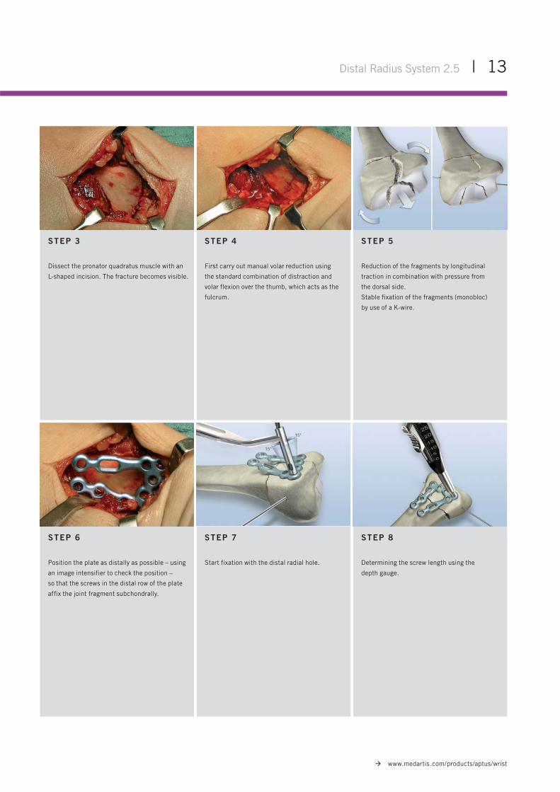
STEP 3
Dissect the pronator quadratus muscle with an
L-shaped incision. The fracture becomes visible.
STEP 5
Reduction of the fragments by longitudinal
traction in combination with pressure from
the dorsal side.
Stable fixation of the fragments (monobloc)
by use of a K-wire.
STEP 6
Position the plate as distally as possible – using
an image intensifier to check the position –
so that the screws in the distal row of the plate
affix the joint fragment subchondrally.
STEP 4
First carry out manual volar reduction using
the standard combination of distraction and
volar flexion over the thumb, which acts as the
fulcrum.
STEP 7
Start fixation with the distal radial hole.
STEP 8
Determining the screw length using the
depth gauge.
14 | Distal Radius System 2.5
www.medartis.com/products/aptus/wrist
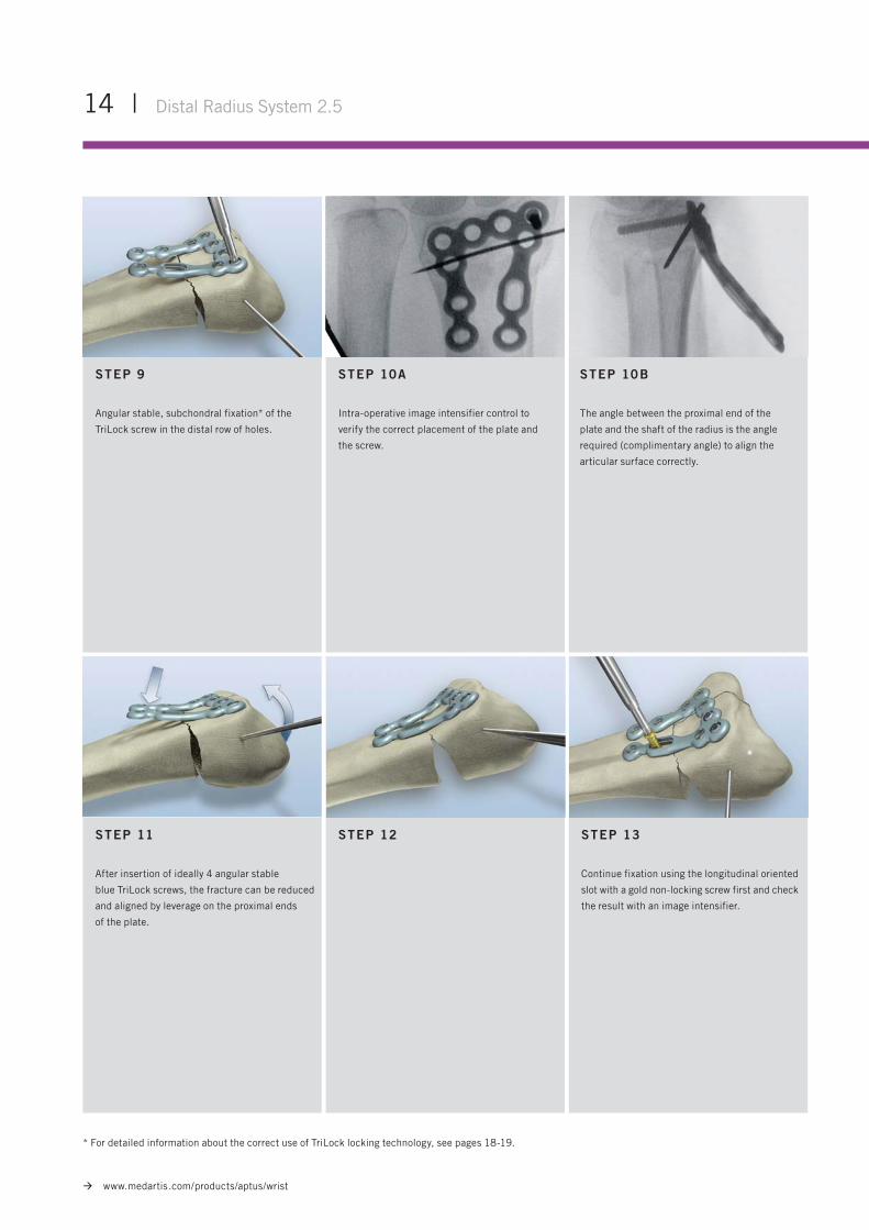
STEP 10B
The angle between the proximal end of the
plate and the shaft of the radius is the angle
required (complimentary angle) to align the
articular surface correctly.
* For detailed information about the correct use of TriLock locking technology, see pages 18-19.
STEP 13
Continue fixation using the longitudinal oriented
slot with a gold non-locking screw first and check
the result with an image intensifier.
STEP 9
Angular stable, subchondral fixation* of the
TriLock screw in the distal row of holes.
STEP 10A
Intra-operative image intensifier control to
verify the correct placement of the plate and
the screw.
STEP 11
After insertion of ideally 4 angular stable
blue TriLock screws, the fracture can be reduced
and aligned by leverage on the proximal ends
of the plate.
STEP 12
Distal Radius System 2.5 | 15
www.medartis.com/products/aptus/wrist
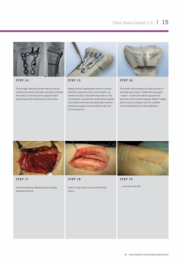
STEP 15
Always perform appropriate checks to ensure
that the screws are of the correct length, are
locked securely in the plate (they have to click
into position), and provide central distal support
(first distal screw row) and preferably subchon-
dral dorsal support (second distal screw row)
for the dorsal rim.
STEP 14
If the image intensifier shows that the correct
anatomical position has been achieved,complete
the fixation of the fracture by angular stable
positioning of the remaining TriLock screws.
STEP 16
The model demonstrates the ideal position of
the plate and screws. It shows the very good
“carrier” construction which supports the
articular surface and the angular stable “bridge”
(which acts as a fixator) over the unstable
comminuted fracture in the metaphysis.
STEP 17
Cover the plate by reattaching the pronator
quadratus muscle.
STEP 18
Insert a small drain and suture the deep
fascia …
STEP 19
… and suture the skin.
16 | Distal Radius System 2.5
www.medartis.com/products/aptus/wrist
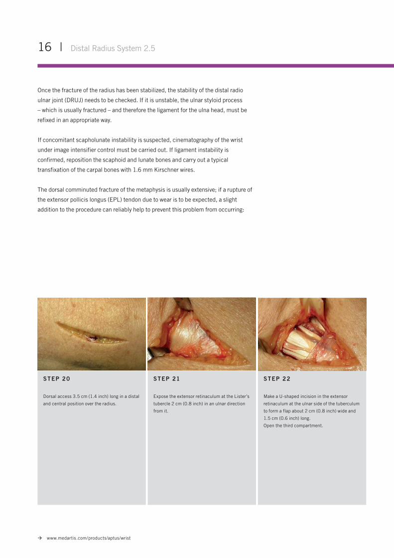
STEP 22
Make a U-shaped incision in the extensor
retinaculum at the ulnar side of the tuberculum
to form a flap about 2 cm (0.8 inch) wide and
1.5 cm (0.6 inch) long.
Open the third compartment.
Once the fracture of the radius has been stabilized, the stability of the distal radio
ulnar joint (DRUJ) needs to be checked. If it is unstable, the ulnar styloid process
– which is usually fractured – and therefore the ligament for the ulna head, must be
refixed in an appropriate way.
If concomitant scapholunate instability is suspected, cinematography of the wrist
under image intensifier control must be carried out. If ligament instability is
confirmed, reposition the scaphoid and lunate bones and carry out a typical
transfixation of the carpal bones with 1.6 mm Kirschner wires.
The dorsal comminuted fracture of the metaphysis is usually extensive; if a rupture of
the extensor pollicis longus (EPL) tendon due to wear is to be expected, a slight
addition to the procedure can reliably help to prevent this problem from occurring:
STEP 20
Dorsal access 3.5 cm (1.4 inch) long in a distal
and central position over the radius.
STEP 21
Expose the extensor retinaculum at the Lister’s
tubercle 2 cm (0.8 inch) in an ulnar direction
from it.
Distal Radius System 2.5 | 17
www.medartis.com/products/aptus/wrist
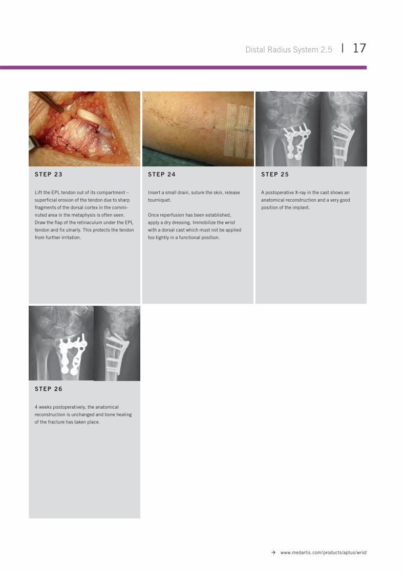
STEP 25
A postoperative X-ray in the cast shows an
anatomical reconstruction and a very good
position of the implant.
STEP 26
4 weeks postoperatively, the anatomical
reconstruction is unchanged and bone healing
of the fracture has taken place.
STEP 23
Lift the EPL tendon out of its compartment –
superficial erosion of the tendon due to sharp
fragments of the dorsal cortex in the commi-
nuted area in the metaphysis is often seen.
Draw the flap of the retinaculum under the EPL
tendon and fix ulnarly. This protects the tendon
from further irritation.
STEP 24
Insert a small drain, suture the skin, release
tourniquet.
Once reperfusion has been established,
apply a dry dressing. Immobilize the wrist
with a dorsal cast which must not be applied
too tightly in a functional position.
18 | Distal Radius System 2.5
www.medartis.com/products/aptus/wrist
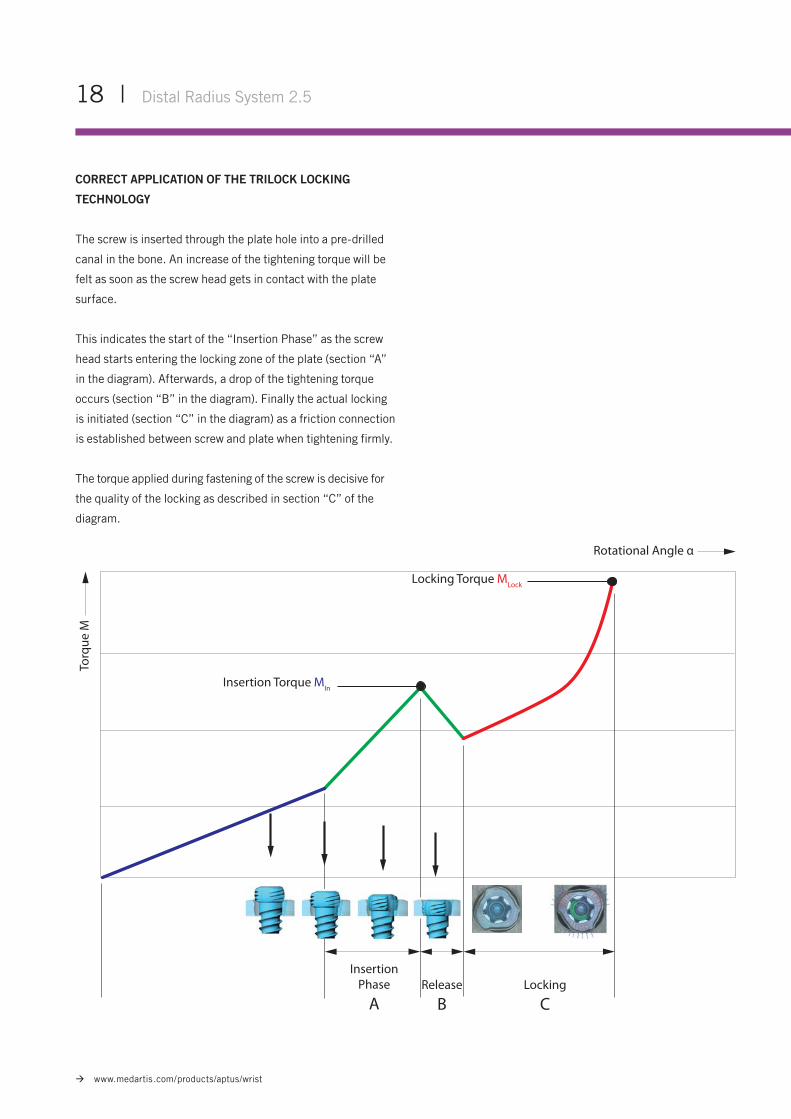
CORRECT APPLICATION OF THE TRILOCK LOCKING
TECHNOLOGY
The screw is inserted through the plate hole into a pre-drilled
canal in the bone. An increase of the tightening torque will be
felt as soon as the screw head gets in contact with the plate
surface.
This indicates the start of the “Insertion Phase” as the screw
head starts entering the locking zone of the plate (section “A”
in the diagram). Afterwards, a drop of the tightening torque
occurs (section “B” in the diagram). Finally the actual locking
is initiated (section “C” in the diagram) as a friction connection
is established between screw and plate when tightening firmly.
The torque applied during fastening of the screw is decisive for
the quality of the locking as described in section “C” of the
diagram.
Insertion Torque MIn
Locking Torque MLock
Insertion Phase
ARelease
BLocking
C
Torq
ue M
Rotational Angle α
Distal Radius System 2.5 | 19
www.medartis.com/products/aptus/wrist
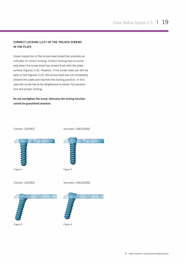
Figure 1
Figure 3
Figure 2
Figure 4
Correct: LOCKED
Correct: LOCKED
Incorrect: UNLOCKED
Incorrect: UNLOCKED
CORRECT LOCKING (±15°) OF THE TRILOCK SCREWS
IN THE PLATE
Visual inspection of the screw head projection provides an
indicator of correct locking. Correct locking has occurred
only when the screw head has locked flush with the plate
surface (figures 1+3). However, if the screw head can still be
seen or felt (figures 2+4), the screw head has not completely
entered the plate and reached the locking position. In this
case the screw has to be retightened to obtain full penetra-
tion and proper locking.
Do not overtighten the screw, otherwise the locking function
cannot be guaranteed anymore.

Medartis AG
Hochbergerstrasse 60E
CH-4057 Basel
T +41 61 633 34 34
F +41 61 633 34 00
www.medartis.com
MMMeMedadartrtisis A AGG
HoHochchbebergrgererststrarassssse e 6060EE
CHCH-4-405057 7 BaBasesel
T T +4+41 1 6161 6 63333 334 44 3434
F F +4+441 6161 6 63333 3 34 44 0000
wwwwwww.w memedadartrtisis.c.ccomm
WRIST-01020001_v2 / © 02.2011, Medartis AG, Switzerland. All technical data subject to alteration.
HEADQUARTERS
Medartis AG | Hochbergerstrasse 60E | 4057 Basel/Switzerland
P +41 61 633 34 34 | F +41 61 633 34 00 | www.medartis.com
SUBSIDIARIES Australia | Austria | France | Germany | Mexico | New Zealand | Poland | UK | USA
For detailed information regarding our subsidiaries and distributors, please visit www.medartis.com.