Embed Size (px)
Citation preview
WPH Series pH & ORP Controller
Instruction Manual
Notice ©2007 WALCHEM Corporation 5 Boynton Road, Holliston, MA 01746 USA (508) 429-1110 All Rights Reserved Printed in USA Proprietary Material The information and descriptions contained herein are the property of WALCHEM Corporation. Such information and descriptions may not be copied or reproduced by any means, or disseminated or distributed without the express prior written permission of WALCHEM Corporation, 5 Boynton Road, Holliston, MA 01746. This document is for information purposes only and is subject to change without notice. Statement of Limited Warranty WALCHEM Corporation warrants equipment of its manufacture, and bearing its identification to be free from defects in workmanship and material for a period of 24 months for electronics and 12 months for mechanical parts and electrodes from date of delivery from the factory or authorized distributor under normal use and service and otherwise when such equipment is used in accordance with instructions furnished by WALCHEM Corporation and for the purposes disclosed in writing at the time of purchase, if any. WALCHEM Corporation's liability under this warranty shall be limited to replacement or repair, F.O.B. Holliston, MA U.S.A. of any defective equipment or part which, having been returned to WALCHEM Corporation, transportation charges prepaid, has been inspected and determined by WALCHEM Corporation to be defective. Replaceable elastomeric parts and glass components are expendable and are not covered by any warranty. THIS WARRANTY IS IN LIEU OF ANY OTHER WARRANTY, EITHER EXPRESS OR IMPLIED, AS TO DESCRIPTION, QUALITY, MERCHANTABILITY, FITNESS FOR ANY PARTICULAR PURPOSE OR USE, OR ANY OTHER MATTER. P/N 180097.R1 June 2007
Table of Contents Table of Contents ...............................................................................................................................................3 1.0 Introduction........................................................................................................................................1 2.0 Specifications ....................................................................................................................................1
2.1 Measurement Performance ................................................................................................................................ 1 2.2 Electrical: Input/Output........................................................................................................................................ 1
Input Power......................................................................................................................................................... 1 Input Signal ......................................................................................................................................................... 1 Output ................................................................................................................................................................. 2 Agency Approvals ............................................................................................................................................... 2
2.3 Mechanical.......................................................................................................................................................... 3 Controller ............................................................................................................................................................ 3 Flow Switch Manifold Assembly.......................................................................................................................... 3
3.0 Unpacking and Installation...............................................................................................................3 3.1 Unpacking the unit .............................................................................................................................................. 3 3.2 Mounting the electronic enclosure ...................................................................................................................... 3 3.3 Installation........................................................................................................................................................... 4
Electrode Installation........................................................................................................................................... 4 3.4 Icon Definitions ................................................................................................................................................... 5 3.5 Electrical Installation ........................................................................................................................................... 7
4.0 Function Overview ..........................................................................................................................16 4.1 Front Panel ....................................................................................................................................................... 16 4.2 Display .............................................................................................................................................................. 16 4.3 Keypad.............................................................................................................................................................. 17 4.4 Access Code..................................................................................................................................................... 17 4.5 Startup .............................................................................................................................................................. 17
Initial Startup ..................................................................................................................................................... 17 Normal Startup.................................................................................................................................................. 17
4.6 Shutdown.......................................................................................................................................................... 18 5.0 Operation..........................................................................................................................................18
5.1 Main Menu ........................................................................................................................................................ 18 5.2 Sensor Menu..................................................................................................................................................... 20
Cal'd.................................................................................................................................................................. 20 2 Pt Calibration ................................................................................................................................................. 20 1 Pt Calibration ................................................................................................................................................. 24 Days Btwn Cal .................................................................................................................................................. 26 Use Buffer Rec.................................................................................................................................................. 26 Buffer Set .......................................................................................................................................................... 26 Input.................................................................................................................................................................. 26 Self Test............................................................................................................................................................ 26 Sensor Type...................................................................................................................................................... 26
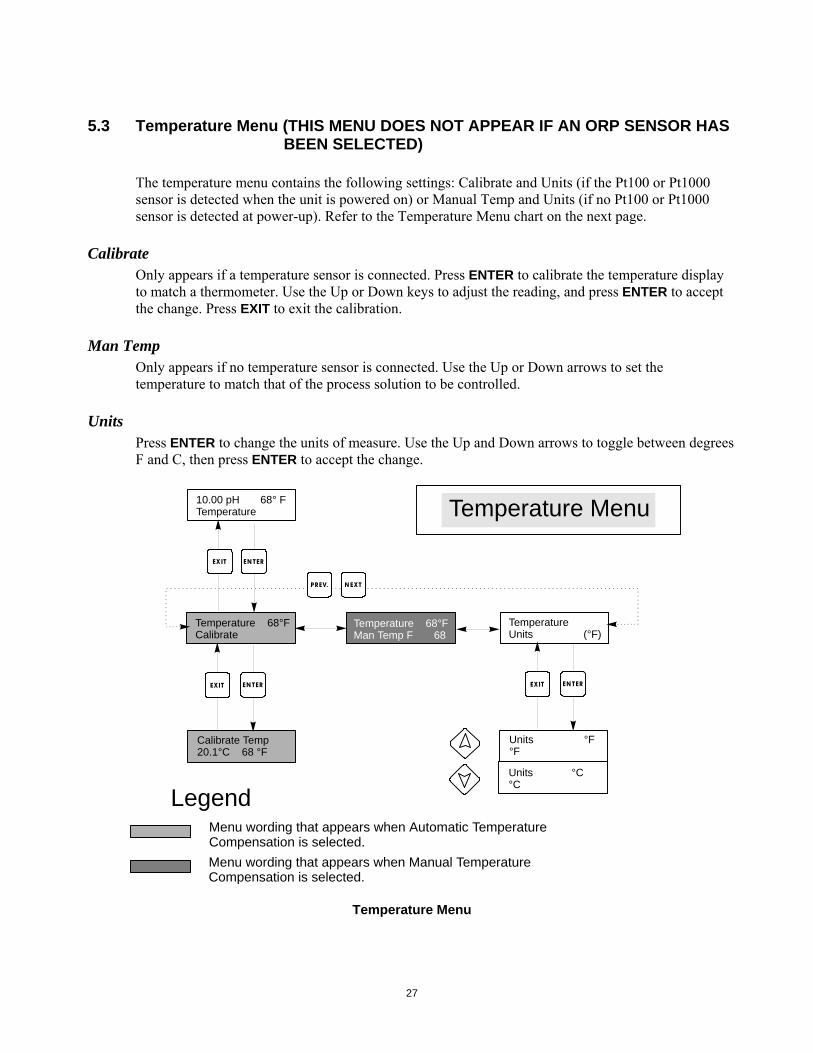
5.3 Temperature Menu (THIS MENU DOES NOT APPEAR IF AN ORP SENSOR HAS BEEN SELECTED) .. 27 Calibrate ........................................................................................................................................................... 27 Man Temp......................................................................................................................................................... 27 Units.................................................................................................................................................................. 27
5.4 Control 1 and Control 2 Menus (FOR ON/OFF CONTROLLERS) .................................................................... 28 Hi/Lo Set Point .................................................................................................................................................. 28 Dead Band........................................................................................................................................................ 28 Time Limit ......................................................................................................................................................... 30 Interlock ............................................................................................................................................................ 30 Control Dir......................................................................................................................................................... 30 HOA .................................................................................................................................................................. 30
5.5 Control 1 and Control 2 Menu (FOR PROPORTIONAL CONTROLLERS)....................................................... 30 Hi/LoSet Point ................................................................................................................................................... 30 Prop Band......................................................................................................................................................... 32 Control Dir......................................................................................................................................................... 32 Min SPM Rate................................................................................................................................................... 32
Max SPM Rate.................................................................................................................................................. 32 Time Limit ......................................................................................................................................................... 33 Interlock ............................................................................................................................................................ 33 HOA .................................................................................................................................................................. 33
5.6 Auxiliary 1 and 2 Menu ..................................................................................................................................... 33 Mode................................................................................................................................................................. 33 Lo Alarm Pt ....................................................................................................................................................... 34 Hi Alarm Pt........................................................................................................................................................ 34 Dead Band........................................................................................................................................................ 34 Probe Wash Sched ........................................................................................................................................... 34 Hold Time.......................................................................................................................................................... 34 HOA .................................................................................................................................................................. 34
5.7 4-20 mA Menu (Optional).................................................................................................................................. 36 Assign Inputs .................................................................................................................................................... 36 4 mA Pt ............................................................................................................................................................. 36 20 mA Pt ........................................................................................................................................................... 36 Calibrate ........................................................................................................................................................... 36 Fixed 4 mA Out ................................................................................................................................................. 36 Fixed 20 mA Out ............................................................................................................................................... 36
5.8 Clock Menu....................................................................................................................................................... 38 Set Clock .......................................................................................................................................................... 38
5.9 Access Code Menu........................................................................................................................................... 39 Enable Y/N........................................................................................................................................................ 39 New Access Code............................................................................................................................................. 39
6.0 Maintenance.....................................................................................................................................41 6.1 Electrode Maintenance ..................................................................................................................................... 41 6.2 Replacing the Fuses ......................................................................................................................................... 42
7.0 Troubleshooting ..............................................................................................................................42 7.1 Error Messages................................................................................................................................................. 42
Calibration Time................................................................................................................................................ 42 Output Timeout ................................................................................................................................................. 42 High Alarm ........................................................................................................................................................ 43 Low Alarm......................................................................................................................................................... 43 Out Range Alarm .............................................................................................................................................. 43 In Range Output................................................................................................................................................ 43 Temp Sensor Err............................................................................................................................................... 44 Probe Error ....................................................................................................................................................... 44 Interlock ............................................................................................................................................................ 44 Check Set Points .............................................................................................................................................. 45
8.0 Service Policy ..................................................................................................................................45
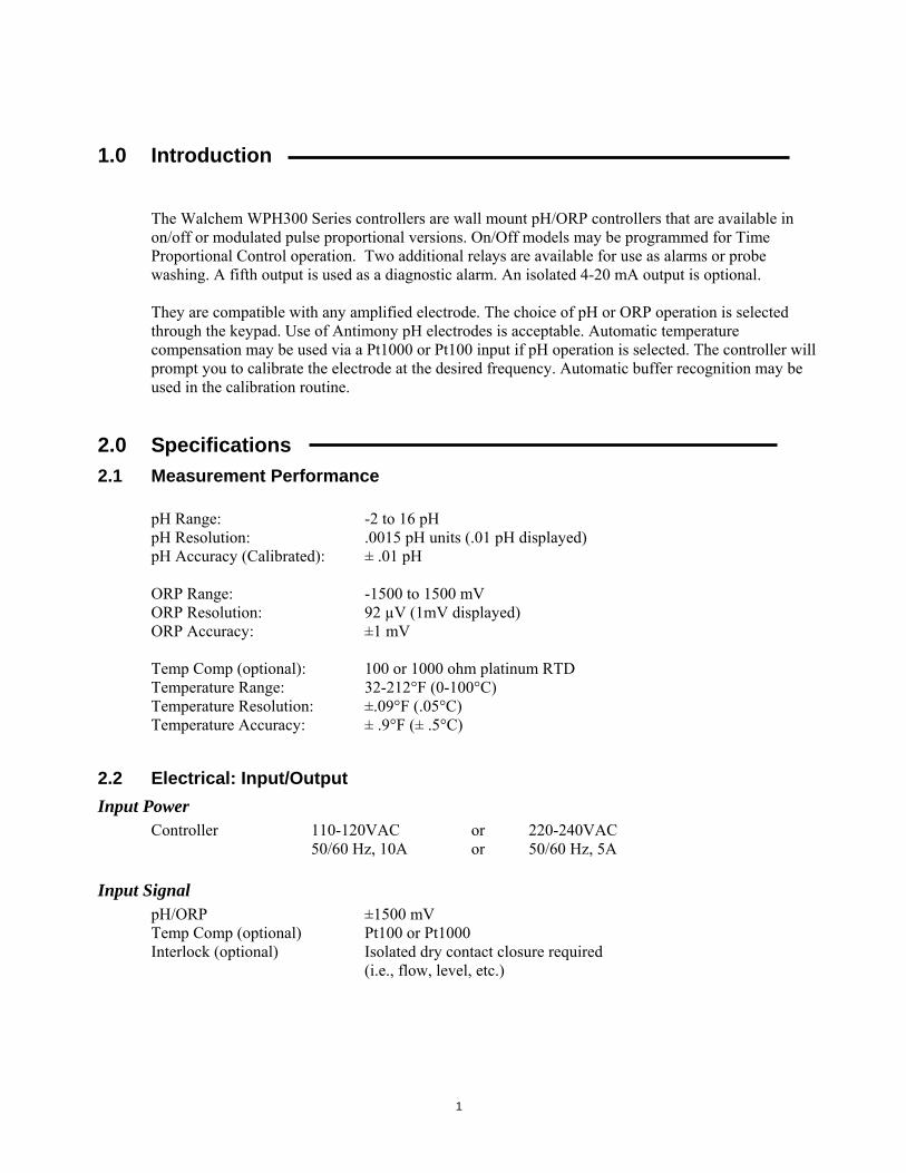
1.0 Introduction The Walchem WPH300 Series controllers are wall mount pH/ORP controllers that are available in on/off or modulated pulse proportional versions. On/Off models may be programmed for Time Proportional Control operation. Two additional relays are available for use as alarms or probe washing. A fifth output is used as a diagnostic alarm. An isolated 4-20 mA output is optional. They are compatible with any amplified electrode. The choice of pH or ORP operation is selected through the keypad. Use of Antimony pH electrodes is acceptable. Automatic temperature compensation may be used via a Pt1000 or Pt100 input if pH operation is selected. The controller will prompt you to calibrate the electrode at the desired frequency. Automatic buffer recognition may be used in the calibration routine.
2.0 Specifications 2.1 Measurement Performance
pH Range: -2 to 16 pH pH Resolution: .0015 pH units (.01 pH displayed) pH Accuracy (Calibrated): ± .01 pH ORP Range: -1500 to 1500 mV ORP Resolution: 92 µV (1mV displayed) ORP Accuracy: ±1 mV Temp Comp (optional): 100 or 1000 ohm platinum RTD Temperature Range: 32-212°F (0-100°C) Temperature Resolution: ±.09°F (.05°C) Temperature Accuracy: ± .9°F (± .5°C)
1
2.2 Electrical: Input/Output Input Power
Controller 110-120VAC or 220-240VAC 50/60 Hz, 10A or 50/60 Hz, 5A
Input Signal pH/ORP ±1500 mV Temp Comp (optional) Pt100 or Pt1000 Interlock (optional) Isolated dry contact closure required (i.e., flow, level, etc.)
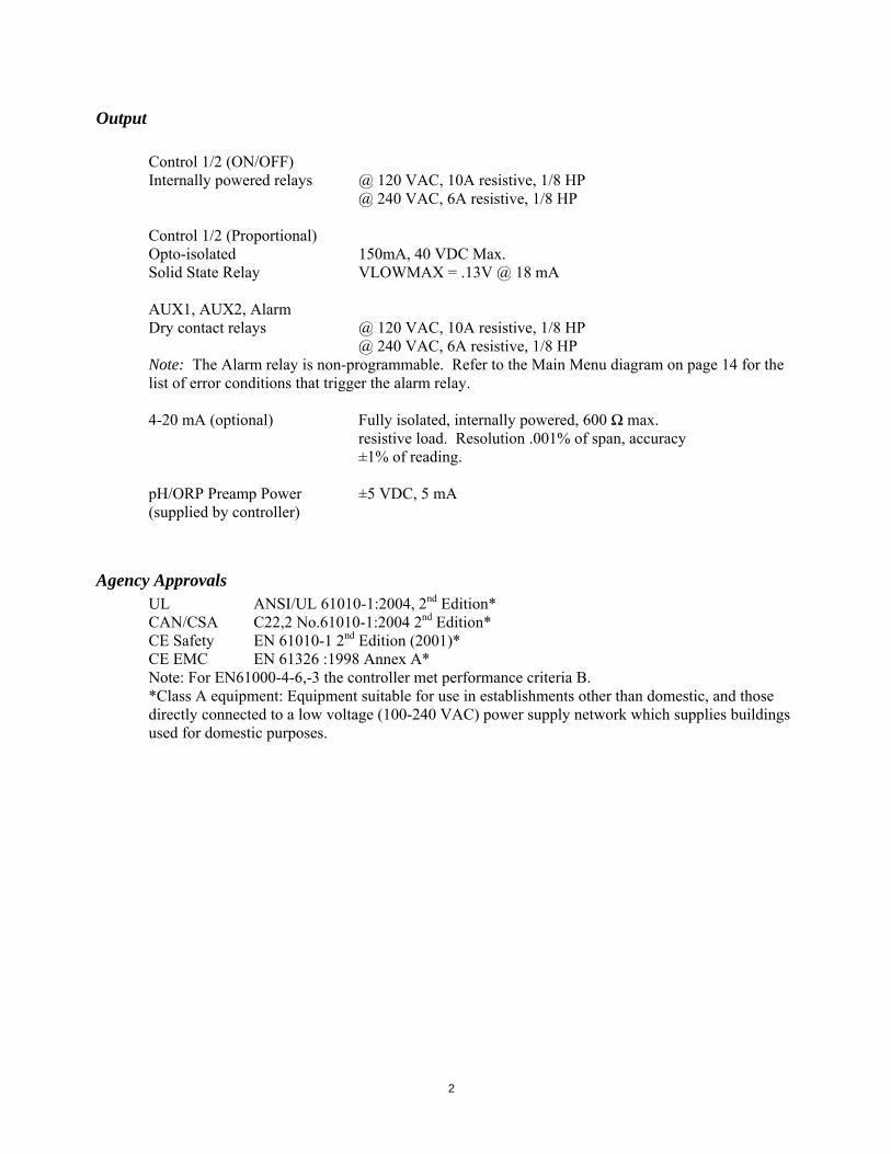
Output
Control 1/2 (ON/OFF) Internally powered relays @ 120 VAC, 10A resistive, 1/8 HP @ 240 VAC, 6A resistive, 1/8 HP Control 1/2 (Proportional) Opto-isolated 150mA, 40 VDC Max. Solid State Relay VLOWMAX = .13V @ 18 mA AUX1, AUX2, Alarm Dry contact relays @ 120 VAC, 10A resistive, 1/8 HP @ 240 VAC, 6A resistive, 1/8 HP Note: The Alarm relay is non-programmable. Refer to the Main Menu diagram on page 14 for the list of error conditions that trigger the alarm relay. 4-20 mA (optional) Fully isolated, internally powered, 600 Ω max. resistive load. Resolution .001% of span, accuracy ±1% of reading. pH/ORP Preamp Power ±5 VDC, 5 mA (supplied by controller)
Agency Approvals
UL ANSI/UL 61010-1:2004, 2nd Edition* CAN/CSA C22,2 No.61010-1:2004 2nd Edition* CE Safety EN 61010-1 2nd Edition (2001)* CE EMC EN 61326 :1998 Annex A* Note: For EN61000-4-6,-3 the controller met performance criteria B. *Class A equipment: Equipment suitable for use in establishments other than domestic, and those directly connected to a low voltage (100-240 VAC) power supply network which supplies buildings used for domestic purposes.
2
2.3 Mechanical Controller
Enclosure: Fiberglass NEMA Rating: NEMA 4X Dimensions: 8.5" x 6.5" x 5.5" Display: 2 x 16 character backlit liquid crystal Operating Ambient Temp: 32 - 122°F (0 - 50°C) Storage Temperature: -20 to 180°F (-29 to 80°C) Shipping Weight: 7 lbs (3kg) (approximately)
Flow Switch Manifold Assembly
Temperature: 140°F (60°C) max Pressure: 150 PSI max Process Connections: ¾” NPTF
3.0 Unpacking and Installation 3.1 Unpacking the unit
Inspect the contents of the carton. Please notify the carrier immediately if there are any signs of damage to the controller or its parts. Contact your distributor if any of the parts are missing. The carton should contain a WPH300 controller and instruction manual. Any options or accessories will be incorporated as ordered.
3.2 Mounting the electronic enclosure
The WPH series controller is supplied with mounting holes on the enclosure. It should be wall mounted with the display at eye level, on a vibration-free surface, utilizing all 4 mounting holes for maximum stability. Use M6 (1/4" diameter) fasteners that are appropriate for the substrate material of the wall. The enclosure is NEMA 4X rated. The maximum operating ambient temperature is 122°F (50°C). The enclosure requires the following clearances: Top: 2" Left: 8" Right: 4" Bottom: 7"
3
3.3 Installation Once the enclosure is mounted, the metering pumps may be located at any distance from the controller. The electrode, once amplified, may be placed up to 1000 feet from the controller. Shielded cable with twisted pairs is required. Always route AC voltage wiring in conduit that is separated by 6 inches from low voltage DC signal lines (such as the electrode signal).
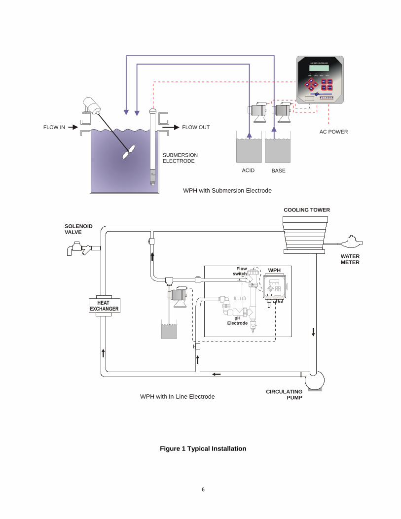
Electrode Installation The WPH controllers are designed to work with most AMPLIFIED pH, ORP or ISE electrodes. When in doubt, follow the electrode manufacturer's instructions for installation. If you have ordered your controller with an external preamplifier pre-wired to the controller, simply attach the electrode to the BNC connector on the preamplifier. If you are using automatic temperature compensation, wire the ATC element to the preamplifier as shown in figure 3. If you have ordered the external preamplifier separately, see figure 3 for wiring instructions. NOTE: The cable between the electrode and the preamplifier is carrying an extremely sensitive high impedance voltage signal. Never cut, splice or otherwise destroy the integrity of the cable or unstable readings and susceptibility to electrical noise will result. Instructions for physically mounting the electrode into the process solution will vary greatly with the type of electrode and circumstances involved in your application. Here are some general guidelines to assist you. Refer to figure 1, Typical Installation. The electrode should be installed such that the measuring surfaces will always stay wet. Many electrodes have to be installed vertically, with the measuring surfaces pointing down. Follow the manufacturer's recommendations if this is the case. If the electrode dries out, a slow response and short life will result. For submersion applications, mount the electrode below the minimum solution level. If the tank will be completely emptied, plan on removing the electrode and storing it in tap water (NOT DI water) or pH 4 buffer solution while the tank is empty. If this is not desirable, a recirculation loop may be installed with the electrode mounted in-line. The WEL electrode cable is not waterproof and must be protected from moisture by connecting a pipe to the top of the electrode housing. The opposite end of the pipe should also be protected from moisture using a cable gland. When submerging the electrode, make sure the cable is protected by a length of pipe, sealed at the top using a cable gland.
4
For in-line applications, where the electrode is installed in a pipe, the electrode should be placed on the discharge side of the pump (under positive pressure). A "U" trap should be included so that if flow stops, the electrode is still immersed in the solution. If the flow through the pipe can not be shut down for cleaning and calibrating the electrode, install the electrode in a by-pass line with isolation valves to allow for electrode removal.The electrode should be installed in an area where there is good solution movement and where it will respond rapidly to chemical additions. The placement of the electrode relative to the placement of chemical replenishment, along with the quality of the mixing and replenishment flow rate, is critical to accurate control. When connecting pipe to the in-line mounting tee of a WEL electrode, use no more than 3 wraps of Teflon tape and only screw in the pipe to FINGER TIGHT. Over-tightening will crack the tee. Do not use pipe dope to seal the threads of the flow switch because the clear plastic will crack!
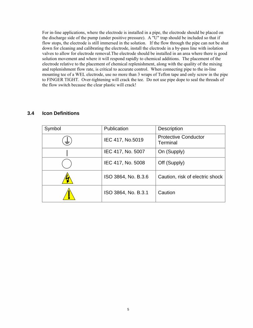
3.4 Icon Definitions
Symbol Publication Description
IEC 417, No.5019 Protective Conductor Terminal
IEC 417, No. 5007 On (Supply)
IEC 417, No. 5008 Off (Supply)
ISO 3864, No. B.3.6 Caution, risk of electric shock
ISO 3864, No. B.3.1 Caution
5
CIRCULATING PUMP
SOLENOIDVALVE
COOLING TOWER
WATERMETER
WPH
WPH with In-Line Electrode
pH/ORP CONTROLLER
CTRL1 AUX1CTRL2 AUX2
NEXTPREV.
EXIT ENTER
ACID BASE
SUBMERSIONELECTRODE
pHPROBE
AC POWERFLOW OUTFLOW IN
WPH with Submersion Electrode
pHElectrode
Flowswitch
Figure 1 Typical Installation
6
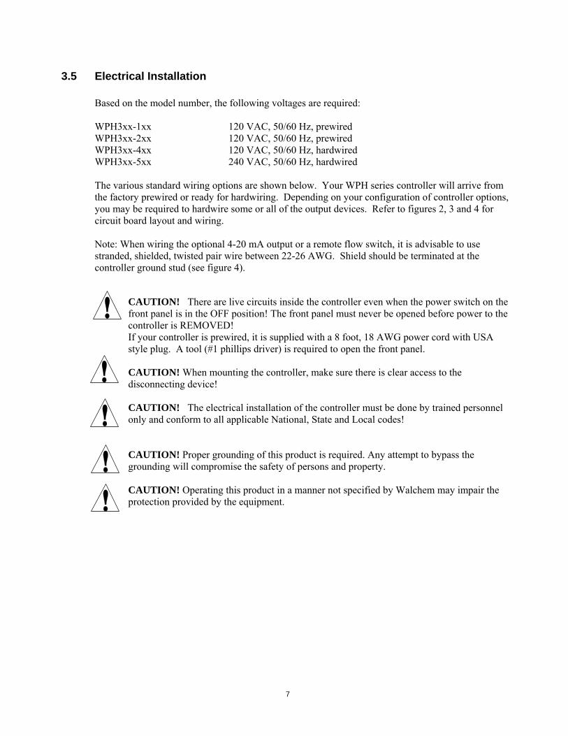
3.5 Electrical Installation Based on the model number, the following voltages are required: WPH3xx-1xx 120 VAC, 50/60 Hz, prewired WPH3xx-2xx 120 VAC, 50/60 Hz, prewired WPH3xx-4xx 120 VAC, 50/60 Hz, hardwired WPH3xx-5xx 240 VAC, 50/60 Hz, hardwired The various standard wiring options are shown below. Your WPH series controller will arrive from the factory prewired or ready for hardwiring. Depending on your configuration of controller options, you may be required to hardwire some or all of the output devices. Refer to figures 2, 3 and 4 for circuit board layout and wiring. Note: When wiring the optional 4-20 mA output or a remote flow switch, it is advisable to use stranded, shielded, twisted pair wire between 22-26 AWG. Shield should be terminated at the controller ground stud (see figure 4).
CAUTION! There are live circuits inside the controller even when the power switch on the front panel is in the OFF position! The front panel must never be opened before power to the controller is REMOVED! If your controller is prewired, it is supplied with a 8 foot, 18 AWG power cord with USA style plug. A tool (#1 phillips driver) is required to open the front panel. CAUTION! When mounting the controller, make sure there is clear access to the disconnecting device! CAUTION! The electrical installation of the controller must be done by trained personnel only and conform to all applicable National, State and Local codes!
CAUTION! Proper grounding of this product is required. Any attempt to bypass the grounding will compromise the safety of persons and property. CAUTION! Operating this product in a manner not specified by Walchem may impair the protection provided by the equipment.
7
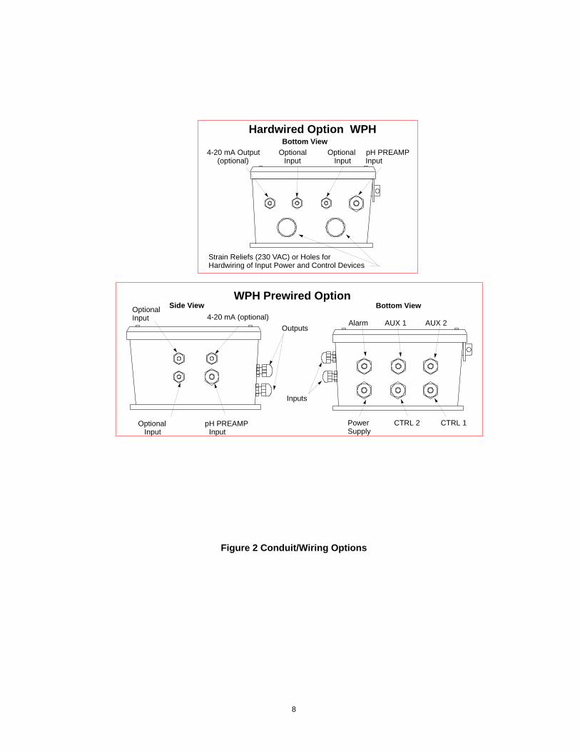
Power CTRL 2 CTRL 1Supply
Alarm AUX 1 AUX 2
Inputs
Outputs
Optional Input 4-20 mA (optional)
Side View Bottom View
Optional Input
pH PREAMP Input
WPH Prewired Option
Bottom View4-20 mA Output Optional Optional pH PREAMP (optional) Input Input Input
Strain Reliefs (230 VAC) or Holes forHardwiring of Input Power and Control Devices
Hardwired Option WPH
Figure 2 Conduit/Wiring Options
8
NEUNEUTRAL
HOT
F2
TB3TB2
F1
(GroundingStud)
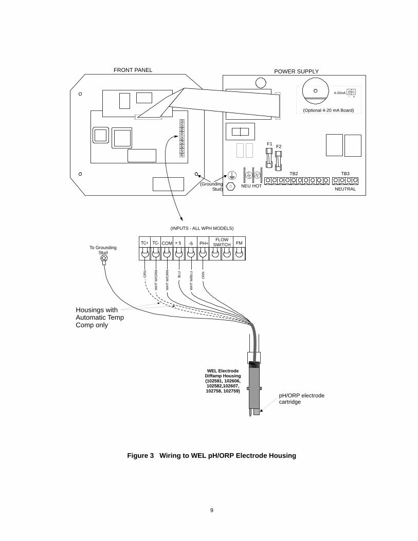
(INPUTS - ALL WPH MODELS)
+_4-20mA
(Optional 4-20 mA Board)
COM PH+FLOW
SWITCH FMTo Grounding
Stud
-5
WEL ElectrodeDiffamp Housing(102581, 102606,102582,102607,102758, 102759)
FRONT PANEL POWER SUPPLY
GR
N
WH
T W
/GR
N
WH
T W
/OR
N
BLU
WH
T W
/BLU
OR
N
Housings withAutomatic TempComp only
pH/ORP electrodecartridge
Figure 3 Wiring to WEL pH/ORP Electrode Housing
9
NEUNEUTRAL
HOT
F2
TB3TB2
F1
(GroundingStud)
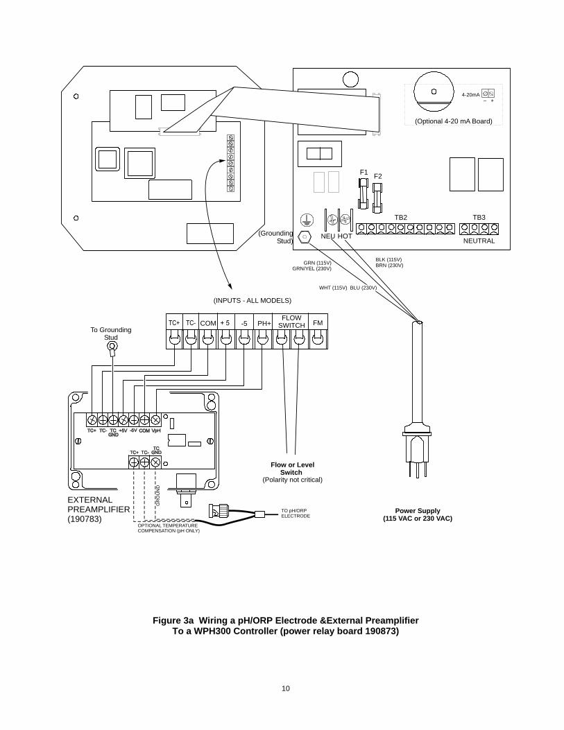
(INPUTS - ALL MODELS)
(Polarity not critical)
BLK (115V) BRN (230V)
+_4-20mA
Flow or Level Switch
Power Supply(115 VAC or 230 VAC)
(Optional 4-20 mA Board)
GRN (115V)GRN/YEL (230V)
WHT (115V) BLU (230V)
COM PH+FLOW
SWITCH FMTo Grounding
Stud
-5
TO pH/ORPELECTRODE
OPTIONAL TEMPERATURECOMPENSATION (pH ONLY)
GR
OU
ND
EXTERNALPREAMPLIFIER(190783)
Figure 3a Wiring a pH/ORP Electrode &External Preamplifier To a WPH300 Controller (power relay board 190873)
10
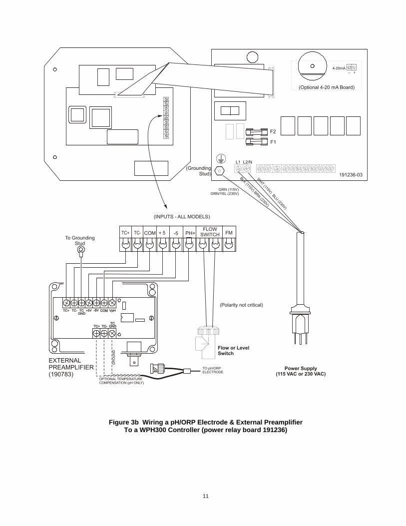
Figure 3b Wiring a pH/ORP Electrode & External Preamplifier To a WPH300 Controller (power relay board 191236)
11
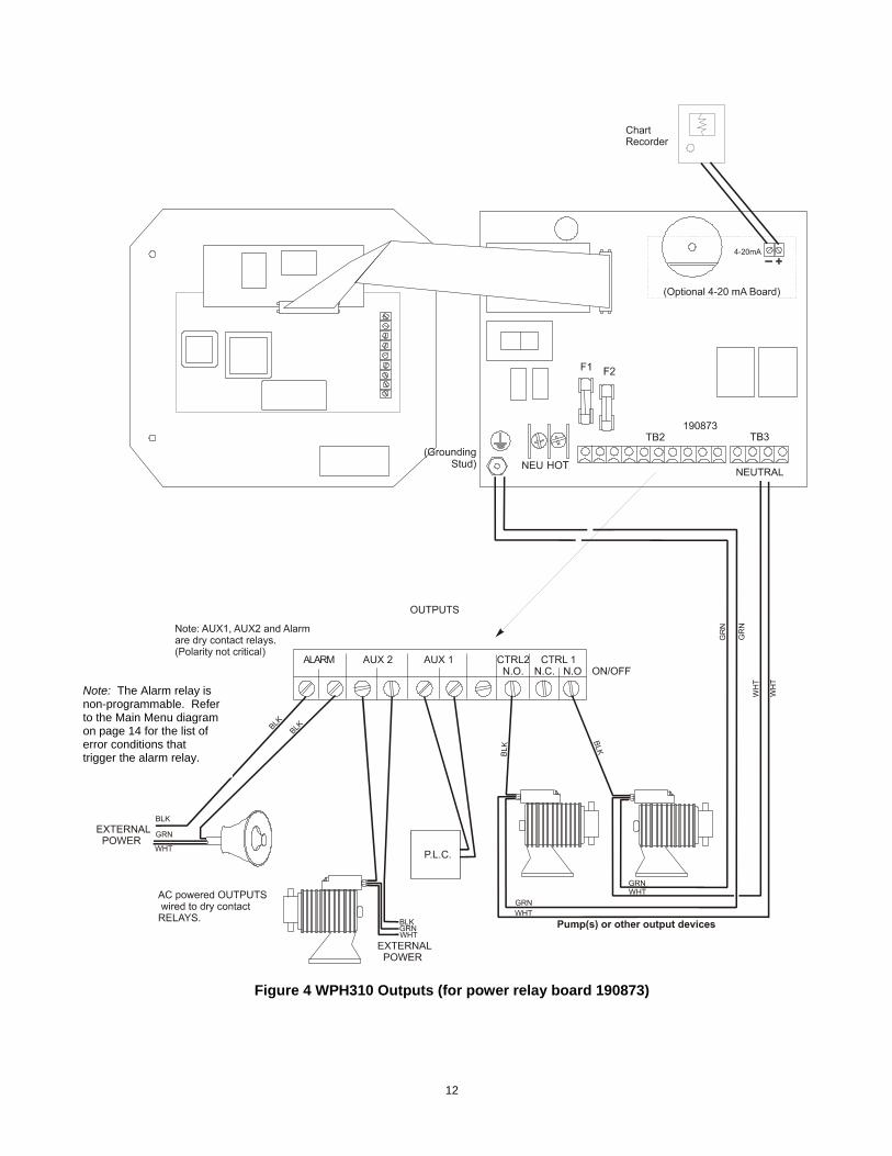
Note: The Alarm relay is non-programmable. Refer to the Main Menu diagram on page 14 for the list of error conditions that trigger the alarm relay.
Figure 4 WPH310 Outputs (for power relay board 190873)
12
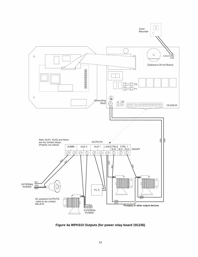
Figure 4a WPH310 Outputs (for power relay board 191236)
13
Note: The Alarm relay is non-programmable. Refer to the Main Menu diagram on page 14 for the list of error conditions that trigger the alarm relay.
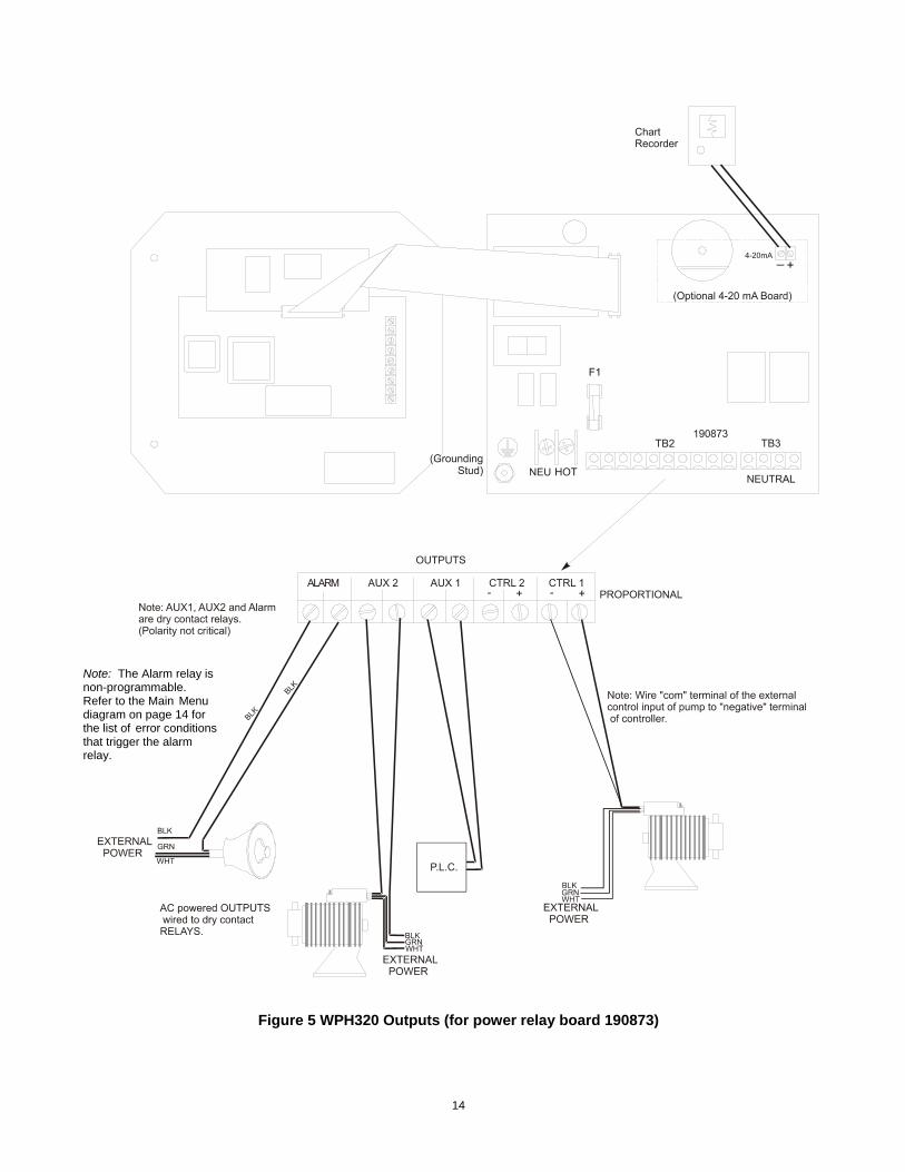
Figure 5 WPH320 Outputs (for power relay board 190873)
14
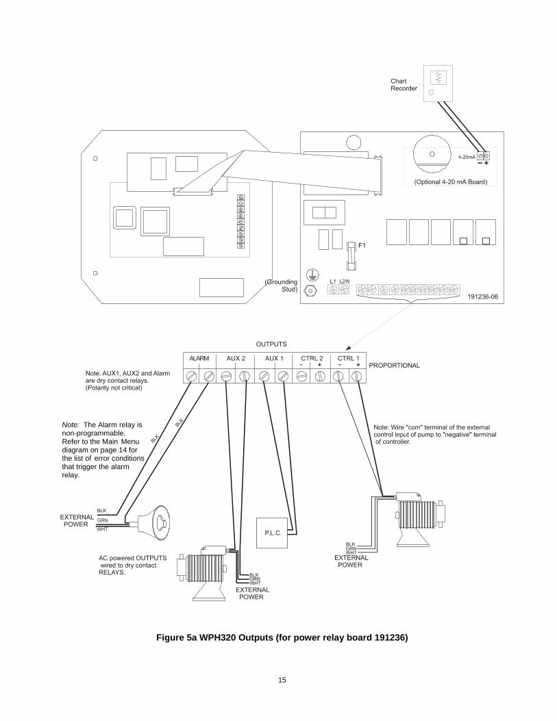
Note: The Alarm relay is non-programmable. Refer to the Main Menu diagram on page 14 for the list of error conditions that trigger the alarm relay.
Figure 5a WPH320 Outputs (for power relay board 191236)
15
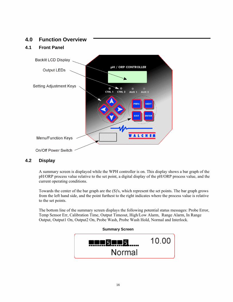
4.0 Function Overview 4.1 Front Panel
4.2 Display
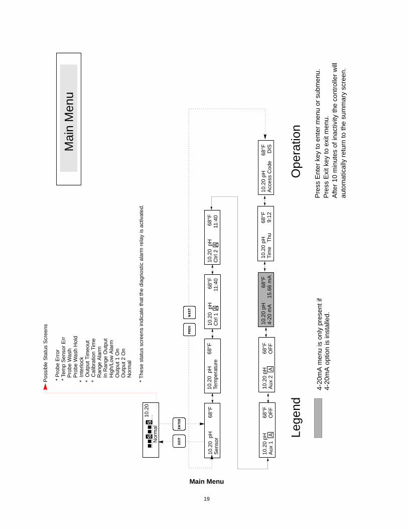
A summary screen is displayed while the WPH controller is on. This display shows a bar graph of the pH/ORP process value relative to the set point, a digital display of the pH/ORP process value, and the current operating conditions. Towards the center of the bar graph are the (S)'s, which represent the set points. The bar graph grows from the left hand side, and the point furthest to the right indicates where the process value is relative to the set points. The bottom line of the summary screen displays the following potential status messages: Probe Error, Temp Sensor Err, Calibration Time, Output Timeout, High/Low Alarm, Range Alarm, In Range Output, Output1 On, Output2 On, Probe Wash, Probe Wash Hold, Normal and Interlock.
Summary Screen
16
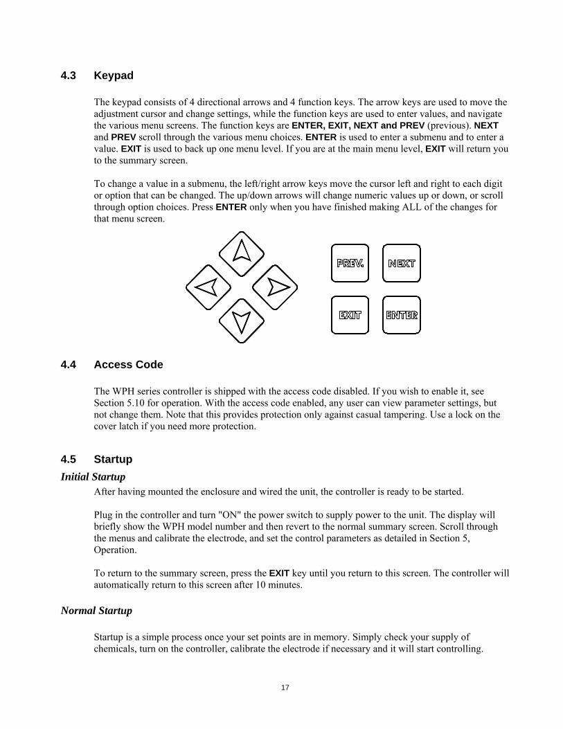
4.3 Keypad The keypad consists of 4 directional arrows and 4 function keys. The arrow keys are used to move the adjustment cursor and change settings, while the function keys are used to enter values, and navigate the various menu screens. The function keys are ENTER, EXIT, NEXT and PREV (previous). NEXT and PREV scroll through the various menu choices. ENTER is used to enter a submenu and to enter a value. EXIT is used to back up one menu level. If you are at the main menu level, EXIT will return you to the summary screen. To change a value in a submenu, the left/right arrow keys move the cursor left and right to each digit or option that can be changed. The up/down arrows will change numeric values up or down, or scroll through option choices. Press ENTER only when you have finished making ALL of the changes for that menu screen.
4.4 Access Code
The WPH series controller is shipped with the access code disabled. If you wish to enable it, see Section 5.10 for operation. With the access code enabled, any user can view parameter settings, but not change them. Note that this provides protection only against casual tampering. Use a lock on the cover latch if you need more protection.
4.5 Startup Initial Startup
After having mounted the enclosure and wired the unit, the controller is ready to be started. Plug in the controller and turn "ON" the power switch to supply power to the unit. The display will briefly show the WPH model number and then revert to the normal summary screen. Scroll through the menus and calibrate the electrode, and set the control parameters as detailed in Section 5, Operation. To return to the summary screen, press the EXIT key until you return to this screen. The controller will automatically return to this screen after 10 minutes.
Normal Startup Startup is a simple process once your set points are in memory. Simply check your supply of chemicals, turn on the controller, calibrate the electrode if necessary and it will start controlling.
17
4.6 Shutdown To shut the WPH controller down, simply turn off the power switch. Programming remains in memory. The electrode must be stored with the measuring surfaces wet. If an extended shutdown will result in the electrode dehydrating, it must be removed from its position in the process and stored in pH 4 buffer solution.
5.0 Operation These units control continuously while power is applied. Programming is accomplished via the local keypad and display. To view the top level menu, press any key. The menu structure is grouped by inputs and outputs. Each input has its own setup menu for calibration and unit of measure selection as needed. Each output has its own setup menu including set points, timer values, direction of control, etc. as needed. After 10 minutes of inactivity in the menu, the display will return to the summary screen. Keep in mind that even while browsing through the menus, the unit is still controlling.
5.1 Main Menu The exact configuration of your WPH controller determines which menus are available as you scroll through the settings. Certain menus are only available if you select certain options. All settings are grouped under the following main menu items: Sensor Temperature Control 1 Control 2 Auxiliary 1 Auxiliary 2 4-20 mA (Only if 4-20 mA option circuit board is installed) Time Access Code The NEXT key travels forward through this list while the PREV key travels backwards through the list. Pressing ENTER will enter the lower level menu that is currently displayed.
18
10.2
0 p
H
68°F
Sens
or10
.20
pH
68
°FC
trl 1
A
11:
40
Pos
sibl
e S
tatu
s S
cree
ns
* P
robe
Err
or *
Tem
p Se
nsor
Err
P
robe
Was
h
Pro
be W
ash
Hol
d*
Inte
rlock
* O
utpu
t Tim
eout
* C
alib
ratio
n Ti
me
R
ange
Ala
rm
In R
ange
Out
put
H
igh/
Low
Ala
rm
Out
put 1
On
O
utpu
t 2 O
n
Nor
mal
* Th
ese
stat
us s
cree
ns in
dica
te th
at th
e di
agno
stic
ala
rm re
lay
is a
ctiv
ated
.
10.2
0 p
H
68°F
Ctrl
2 A
1
1:40
10.2
0 p
H
6
8°F
Tem
pera
ture
10.2
0 pH
6
8°F
Aux
1
A
OFF
10.2
0 pH
68
°FTi
me
Thu
9:1
210
.20
pH
68°
F4-
20 m
A
15.
66 m
A10
.20
pH
68°F
Aux
2
A
OFF
Mai
n M
enu
Pre
ss E
nter
key
to e
nter
men
u or
sub
men
u.P
ress
Exi
t key
to e
xit m
enu.
Afte
r 10
min
utes
of i
nact
ivity
the
cont
rolle
r will
auto
mat
ical
l y re
turn
to th
e su
mm
ary
scre
en.
NEX
TP
REV
.
ENTE
REX
IT
Ope
ratio
nLe
gend
4-20
mA
men
u is
onl
y pr
esen
t if
4-20
mA
opt
ion
is in
stal
led.
S10
.20
Nor
mal
S
10.2
0 pH
6
8°F
Acc
ess
Cod
e
DIS
Main Menu
19
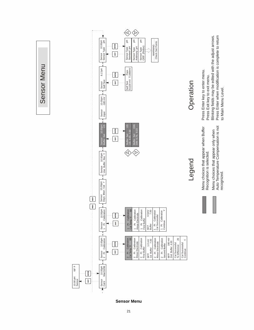
5.2 Sensor Menu The sensor menu provides the following settings: Calibration history (informational only), 2 point calibration, 1 point calibration, pH/ORP selection, and other calibration menus. Each is discussed in detail below. Refer to the Sensor Menu chart on the next page. Note: If you are programming the unit for the first time, press the PREV key once, and set the "Sensor Type" menu first to choose standard pH, antimony pH, or ORP. Then press PREV three times to get to the "Use Buffer Rec"menu and choose whether you want to use automatic buffer recognition or not. Then press ENTER.
Cal'd Displays the date of the last electrode calibration.
2 Pt Calibration Press the ENTER key to perform a 2 point calibration of the electrode. Note: 2 point calibration instructions are given in the following order: pH electrodes, using Auto Buffer Recognition, pH electrodes, not using Auto Buffer Recognition, ORP electrodes (Auto Buffer Recognition not available) 2 Pt Calibration for pH electrodes, using Auto Buffer Recognition: If using manual temperature compensation, the first display will be: Cal Temp °F/C 68 Use the arrow keys to enter the actual temperature of the buffer solutions. If using automatic temperature compensation, this display will not appear. Press ENTER to continue. Rinse Electrode Remove the electrode from the process and rinse it off. Press ENTER to go to the next step. First Buffer This is a prompt to place the electrode in the first buffer. In a few seconds the controller will automatically go to the next step. 1st Buffer 7.00 The top line will show the temperature and the mV output from the electrode. The bottom line will read "1st Buffer" on the left hand side and either "??.??" or a pH value on the right hand side. If it reads a pH value, that means that it has recognized the buffer solution. Once the buffer value is recognized, it will stop flashing and the mV value will begin flashing. Once this has stabilized, it will stop flashing and go on to the next step.
20
21
. . .
. WA
RN
ING
. . .
.C
heck
Set
Poi
nts
Sens
or
10
.00p
HC
al'd
Mar
/10/
96S
enso
r
10.
00pH
2
Pt
Cal
ibra
tion
2
Pt
Cal
ibra
tion
Rin
se E
lect
rode
2
Pt
Cal
ibra
tion
Sec
ond
Buf
fer
Cal
Suc
c ess
ful
% D
iffer
ence
20
2
Pt
Cal
ibra
tion
Firs
t Buf
fer
68°F
1
80 m
V2n
d B
uffe
r 4 .
00
2
Pt
Cal
ibra
tion
Rin
se E
lect
rode
Cal
Suc
cess
ful
Con
tinue
Y
1 P
t C
alib
ratio
nC
onti n
ue
Y
68°F
1
.0 m
V1s
t B
uffe
r
7.0
0
Sens
or
10
.00p
H1
P
t C
alib
ratio
n
1
Pt
Cal
ibra
tion
Rin
se E
lect
rode
1
Pt
Cal
ibra
tion
Firs
t Buf
fer
1
Pt
Cal
ibra
tion
Cal
Suc
cess
ful
68 F
0.5
mV
Buffe
r
7.
00
Sen
sor
1
0.00
pHD
ays
Btw
n C
al
7S
enso
r
10.
00pH
Use
Buf
fer
Rec
YS
enso
r
10.
00pH
Buf
fer
Set
U
S
Buf
fer
Set
U
SU
S 4
.00,
7. 0
0
. .Se
nsor
Typ
e
pH
Stan
dard
pH
Sen
sor T
ype
pHA
ntim
ony
pH
Sen
sor T
ype
pHO
RP
(Red
ox)
Buf
fer
Set
DIN
DIN
6.7
5, 9
.23
. .
Sen
sor
1
0.00
pHS
enso
r Typ
e
pH
10.0
0 pH
68°
FS
enso
r
Sens
or M
enu
Men
u ch
oice
s th
at a
ppea
r whe
n B
uffe
r R
ecog
nitio
n is
sel
ecte
d.Pr
ess
Ent
er k
ey to
ent
er m
enu.
Pres
s E
xit k
ey to
exi
t men
u.Bl
inki
ng fi
elds
may
be
edite
d w
ith th
e ad
just
arro
ws.
Pres
s E
nter
whe
n m
odifi
catio
n is
com
plet
e to
retu
rnto
Mai
n M
enu
Leve
l.
NEX
TP
REV
.
ENTE
REX
IT
ENTE
REX
ITEN
TER
EXIT
ENTE
REX
ITEN
TER
EXIT
Lege
ndO
pera
tion
Sen
sor
1
0.00
pHIn
put
-180
mV
Sen
sor
8.17
pHS
elf T
est
Sel
f Tes
t
P
ass
S11
30 m
V T
1368
mV
ENTE
REX
IT
2
Pt
Cal
ibra
tion
Cal
Tem
p °F
68
1
Pt
Cal
ibra
tion
Cal
Tem
p °F
68
Men
u ch
oice
s th
at a
ppea
r onl
y w
hen
Auto
Tem
pera
ture
Com
pens
atio
n is
not
reco
gniz
ed.
Sensor Menu
If it reads "??.??", that means it hasn't recognized the buffer solution because the mV output of the electrode is too far away from a standard buffer solution's theoretical mV value. If it can't recognize the buffer solution, the controller will beep and display "Unknown Buffer", and then display its best guess. Press ENTER to accept that guess, or change the value to the correct one using the arrow keys. If you press ENTER when it reads “??.??”, the display will switch to “Buffer Override” and allow you to manually enter the buffer value. Rinse Electrode Remove the electrode from the first buffer solution and rinse it off with water. Press ENTER to continue. Second Buffer Place the electrode in the second buffer solution. The controller automatically advances. 2nd Buffer 4.00 The top line will display the temperature and mV readings, which will blink until they become stable. The bottom line will say "2nd Buffer" on the left hand side, either display the pH of the buffer solution or "??.??" on the right hand side and will go to the next step or display "Unknown Buffer" as in 1st Buffer above. Cal Successful/Cal Failed If the electrode response is good, then the display will read "Cal Successful". If the mV output of the electrode did not change enough between the two buffer solutions, it will read "Cal Failed". A failure usually means that the electrode needs to be cleaned, or replaced. It will also display the % difference from the theoretical slope. A failure occurs if the slope is more than 80% different than theoretical. See Troubleshooting Section for “Probe Error” if calibration failed. Continue Y The controller will hold this display until you have replaced the electrode in the process, and press ENTER. Control will not begin until ENTER is pressed, or 10 minutes go by. If calibration failed, control will begin using old calibration setpoints. 2 Pt Calibration for pH electrodes, not using Auto Buffer Recognition: If using manual temperature compensation, the first display will be: Cal Temp °F/C 68 Use the arrow keys to enter the actual temperature of the buffer solutions. If using automatic temperature compensation, this display will not appear. Press ENTER to continue. Rinse Electrode Remove the electrode from the process and rinse it off. Press ENTER to go to the next step. First Buffer This is a prompt to place the electrode in the first buffer. In a few seconds the controller will automatically go to the next step. 1st Buffer 7.00 The bottom line will display "1st Buffer" on the left hand side and "7.00" on the right hand side. Use the arrow keys to set the pH value of the 1st buffer, then press ENTER. The top line will now show the temperature and the mV input from the electrode. The mV will blink until the value is stable. The controller will automatically go onto the next step or you may press ENTER to go to the next step.
22
Rinse Electrode Remove the electrode from the buffer and rinse it off. Press ENTER to go to the next step. Second Buffer This is a prompt to place the electrode in the second buffer. Again, in a few seconds the controller will automatically go to the next step. 2nd Buffer 4.00 The bottom line will display "2nd Buffer" on the left hand side and "4.00" on the right hand side. Use the arrow keys to set the pH value of the 2nd buffer, then press ENTER. The top line will now show the temperature and the mV input from the electrode. The mV will blink until the value is stable. The controller will automatically go onto the next step or you may press ENTER to go to the next step. The controller will go on to the next step once the mV signal is stable. Cal Successful/Cal Failed If the electrode response is good, then the display will read "Cal Successful". If the mV output of the electrode did not change enough between the two buffer solutions, it will read "Cal Failed". A failure usually means that the electrode needs to be cleaned, or replaced. It will also display the % difference from theoretical slope. A failure occurs if the slope is more than 80% different than theoretical. Continue Y The controller will hold this display until you replace the electrode in the process and press ENTER. Control will not begin until ENTER is pressed or 10 minutes go by. 2 Pt Calibration for ORP electrodes (no Auto Buffer Recognition available): Rinse Electrode Remove the electrode from the process and rinse it off. Press ENTER to go to the next step. First Buffer This is a prompt to place the electrode in the first buffer. In a few seconds the controller will automatically go to the next step. Input XX mV The display will show the mV reading from the electrode. The entire number will blink until the reading is stable, then the display will change to: Buffer XX Now you can change the mV value of the buffer, by using the arrow keys and pressing ENTER. Rinse Electrode Remove the electrode from the buffer and rinse it off. Press ENTER to go to the next step. Second Buffer This is a prompt to place the electrode in the second buffer. Again, in a few seconds the controller will automatically go to the next step. Input XXX mV The display will show the mV reading from the electrode. The entire number will blink until the reading is stable, then the display will change to:
23
Buffer XXX Now you can change the mV value of the buffer, by using the arrow keys and pressing ENTER. Cal Successful/Cal Failed If the electrode response is good, then the display will read "Cal Successful". If the mV output of the electrode did not change enough between the two buffer solutions, it will read "Cal Failed". A failure usually means that the electrode needs to be cleaned, or replaced. Continue Y The controller will hold this display until you replace the electrode in the process and press ENTER. Control will not begin until ENTER is pressed or 10 minutes go by.
1 Pt Calibration Press ENTER to perform a 1 point calibration of the electrode. Note: 1 point calibration instructions are given in the following order: pH electrodes, using Auto Buffer Recognition pH electrodes, not using Auto Buffer Recognition ORP electrodes (Auto Buffer Recognition not available) 1 Pt Calibration for pH Electrodes, using Auto Buffer Recognition: If using manual temperature compensation, the first display will be: Cal Temp °F/C 68 Use the arrow keys to enter the actual temperature of the buffer solutions. If using automatic temperature compensation, this display will not appear. Rinse Electrode Remove the electrode from the process and rinse it off. Press ENTER to go to the next step. First Buffer This is a prompt to place the electrode in the first buffer. In a few seconds the controller will automatically go to the next step. 1st Buffer 4.00 The top line will show the temperature and the mV output from the electrode. These values will blink until they become stable. The bottom line will read "1st Buffer" on the left hand side and either "??.??" or a pH value on the right hand side. If it reads a pH value, that means that it has recognized the buffer solution. The controller will then go on to the next step. If it reads "??.??", that means it hasn't recognized the buffer solution because the mV output of the electrode is too far away from a standard buffer solution's theoretical mV value. If it can't recognize the buffer solution, the controller will beep and display "Unknown Buffer", and then display its best guess. Press ENTER to accept that guess, or change the value to the correct one using the arrow keys. If you press ENTER when it reads “??.??”, the display will switch to “Buffer Override” and allow you to manually enter the buffer value.
24
Cal Successful/Cal Failed If the electrode response is good, then the display will read "Cal Successful". If the controller can not calculate an acceptable slope from that mV reading, it will read "Cal Failed". A failure usually means that the electrode needs to be cleaned or replaced. Continue Y The controller will hold this display until you replace the electrode in the process and press ENTER. Control will not begin until ENTER is pressed or 10 minutes go by. 1 Pt Calibration for pH electrodes, not using Auto Buffer Recognition If using manual temperature compensation, the first display will be: Cal Temp °F/C 68 Use the arrow keys to enter the actual temperature of the buffer solutions. Press ENTER to go on to the next step. If using automatic temperature compensation, this display will not appear. Rinse Electrode Remove the electrode from the process and rinse it off. Press ENTER to go to the next step. First Buffer This is a prompt to place the electrode in the first buffer. In a few seconds the controller will automatically go to the next step. Buffer 4.00 Use the arrow keys to change the value of the buffer being used, then press ENTER. 1st Buffer 4.00 The bottom line will display "1st Buffer" on the left hand side and "4.00" on the right hand side. Use the arrow keys to set the pH value of the 1st buffer, then press ENTER. The top line will now show the temperature and the mV input from the electrode. The mV will blink until the value is stable. The controller will automatically go onto the next step or you may press ENTER to go to the next step. Cal Successful/Cal Failed If the electrode response is good, then the display will read "Cal Successful". If the controller can not calculate an acceptable slope from that mV reading, it will read "Cal Failed". A failure usually means that the electrode needs to be cleaned or replaced. Continue Y The controller will hold this display until you replace the electrode in the process and press ENTER. Control will not begin until ENTER is pressed or 10 minutes go by. 1 Pt Calibration for ORP electrodes (no Auto Buffer Recognition available): Rinse Electrode Remove the electrode from the process and rinse it off. Press ENTER to go to the next step. First Buffer This is a prompt to place the electrode in the first buffer. In a few seconds the controller will automatically go to the next step.
25
Input 96 mV The display will show the mV reading from the electrode. The entire number will blink until the reading is stable, then the display will change to: Buffer 96 Now you can change the mV value displayed to the known value of the buffer, by using the arrow keys and pressing ENTER. Cal Successful/Cal Failed If the electrode response is good, then the display will read "Cal Successful". If the controller can not calculate an acceptable slope from that mV reading, it will read "Cal Failed". A failure usually means that the electrode needs to be cleaned or replaced. Continue Y. The controller will hold this display until you replace the electrode in the process and press ENTER. Control will not begin until ENTER is pressed or 10 minutes go by.
Days Btwn Cal Use the arrow keys to set the number of days that you would like to go by before recalibrating the electrode. The controller will prompt you to recalibrate when that time has expired. Setting the number of days to zero will disable this feature.
Use Buffer Rec Use the Up and Down arrows to toggle between Y (yes) and N (no). If you choose to use automatic buffer recognition, then the controller will recognize which buffer solution the electrode has been placed in. If you choose not to, then you will have to enter the information manually during the 1 or 2 point calibration procedures. Press ENTER to accept the choice displayed.
Buffer Set This menu will only appear if you have decided to use automatic buffer recognition. Press ENTER to change the type of buffers that will be used. Use the Up and Down arrows to toggle between US buffers (pH 4, 7 and 10) or DIN standard buffers (pH 6.75, 9.23, etc.) then press ENTER to make your selection.
Input This menu displays the mV from the electrode. It is useful for troubleshooting.
Self Test Press ENTER to perform a self-test. If it says "FAIL" in the upper right hand corner, try again with the electrode wires disconnected. If it still says “FAIL”, this indicates a problem with the controller which should be returned for repair. If it passes, and you have a problem calibrating, it is an electrode or preamp problem.
Sensor Type Press ENTER to set up the controller to match the type of electrode to be used. Use the Up and Down arrows to toggle between standard pH, antimony pH, and ORP, then press ENTER to make your selection. The controller will warn you to check your set points because the units of measure have changed. Press any key to clear the warning messages.
26
5.3 Temperature Menu (THIS MENU DOES NOT APPEAR IF AN ORP SENSOR HAS BEEN SELECTED)
The temperature menu contains the following settings: Calibrate and Units (if the Pt100 or Pt1000 sensor is detected when the unit is powered on) or Manual Temp and Units (if no Pt100 or Pt1000 sensor is detected at power-up). Refer to the Temperature Menu chart on the next page.
Calibrate Only appears if a temperature sensor is connected. Press ENTER to calibrate the temperature display to match a thermometer. Use the Up or Down keys to adjust the reading, and press ENTER to accept the change. Press EXIT to exit the calibration.
Man Temp Only appears if no temperature sensor is connected. Use the Up or Down arrows to set the temperature to match that of the process solution to be controlled.
Units Press ENTER to change the units of measure. Use the Up and Down arrows to toggle between degrees F and C, then press ENTER to accept the change.
Calibrate Temp20.1°C 68 °F
Units °F°F
Units °C°C
Temperature 68°FCalibrate
Temperature 68°FMan Temp F 68
10.00 pH 68° FTemperature
TemperatureUnits (°F)
Temperature Menu
Menu wording that appears when Automatic TemperatureCompensation is selected.Menu wording that appears when Manual TemperatureCompensation is selected.
EN TEREX IT
EN TEREXIT EN TEREXIT
Legend
N EXTPREV.
Temperature Menu
27
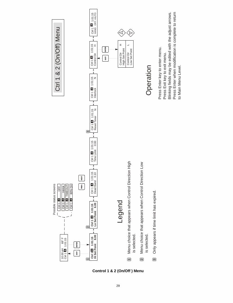
5.4 Control 1 and Control 2 Menus (FOR ON/OFF CONTROLLERS) The Control 1 and Control 2 menus are separate from each other but operate in exactly the same way. Each menu provides the following independent settings: Set Point, Dead Band, Time Limit, Interlock, Control Direction, HOA, Set Point, Dead Band, and Time Limit. The top level menu status line may display the following messages: Off, Intrlck, Timeout, or a time. "Off" indicates that the output is off. "Intrlck" indicates that a signal from a flow switch or level switch is stopping control and has disabled the control outputs. "Timeout" indicates that the output has been on for longer than the maximum time programmed by the user. The time shows that the output is on, and has been for that amount of time. Refer to the Control 1 & 2 menus on the following pages.
Hi/Lo Set Point Use the arrow keys to adjust the display to read the desired set point value. Press ENTER to accept the change.
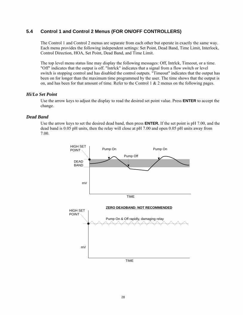
Dead Band Use the arrow keys to set the desired dead band, then press ENTER. If the set point is pH 7.00, and the dead band is 0.05 pH units, then the relay will close at pH 7.00 and open 0.05 pH units away from 7.00.
DEADBAND
HIGH SETPOINT
mV
TIME
Pump On
Pump Off
Pump On
HIGH SETPOINT
mV
TIME
ZERO DEADBAND: NOT RECOMMENDED
Pump On & Off rapidly, damaging relay
28
10.0
0 pH
68°
FC
trl 1
1:0
1:15
Ctr
l 1
1
:01:
15H
i Set
Poi
nt
8.0
0C
trl 1
1:0
1:15
Inte
rlock
NC
trl 1
1:
01:1
5Lo
Set
Poi
nt
6.0
0C
trl 1
1:
01:1
5C
ontro
l Dir
HC
trl 1
1:0
1:15
Tim
e Li
mit
0
:00
Ctrl
1
1
:01:
15H
AND
O
FF >
AUTO
Con
trol D
ir
H
Hig
h Se
t Poi
nt
Con
trol D
ir
L
Low
Set
Poi
nt
Ctrl
1
OFF
Ctrl
1
In
trlck
Ctrl
1
T
IME
OU
T
Ctrl
1 &
2 (O
n/O
ff) M
enu
Pos
sibl
e st
atus
scr
eens
Pre
ss E
nter
key
to e
nter
men
u.P
ress
Exi
t key
to e
xit m
enu.
Blin
king
fiel
ds m
ay b
e ed
ited
with
the
adju
st a
rrow
s.P
ress
Ent
er w
hen
mod
ifica
tion
is c
ompl
ete
to re
turn
to M
ain
Men
u Le
vel.
ENTE
REX
IT
ENTE
REX
IT
Ope
ratio
n
NEX
TP
REV
.
A
A
Ctrl
1
1:01
:15
Dea
d Ba
nd
0.1
0C
trl 1
1:0
1:15
Res
et T
imer
NA
AA
AA
AA
A
Men
u ch
oice
that
app
ears
whe
n C
ontro
l Dire
ctio
n H
igh
is s
elec
ted.
Lege
nd
Men
u ch
oice
that
app
ears
whe
n C
ontro
l Dire
ctio
n Lo
w is
sel
ecte
d.
A A
Onl
y ap
pear
s if
time
limit
has
expi
red.
Ctrl
1
80%
On
A
1 1
2
2
3
3
Control 1 & 2 (On/Off ) Menu
29
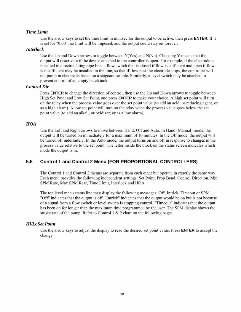
Time Limit Use the arrow keys to set the time limit in min:sec for the output to be active, then press ENTER. If it is set for "0:00", no limit will be imposed, and the output could stay on forever.
Interlock Use the Up and Down arrows to toggle between Y(Yes) and N(No). Choosing Y means that the output will deactivate if the device attached to the controller is open. For example, if the electrode is installed in a recirculating pipe line, a flow switch that is closed if flow is sufficient and open if flow is insufficient may be installed in the line, so that if flow past the electrode stops, the controller will not pump in chemicals based on a stagnant sample. Similarly, a level switch may be attached to prevent control of an empty batch tank.
Control Dir Press ENTER to change the direction of control, then use the Up and Down arrows to toggle between High Set Point and Low Set Point, and press ENTER to make your choice. A high set point will turn on the relay when the process value goes over the set point value (to add an acid, or reducing agent, or as a high alarm). A low set point will turn on the relay when the process value goes below the set point value (to add an alkali, or oxidizer, or as a low alarm).
HOA Use the Left and Right arrows to move between Hand, Off and Auto. In Hand (Manual) mode, the output will be turned on immediately for a maximum of 10 minutes. In the Off mode, the output will be turned off indefinitely. In the Auto mode, the output turns on and off in response to changes in the process value relative to the set point. The letter inside the block on the status screen indicates which mode the output is in.
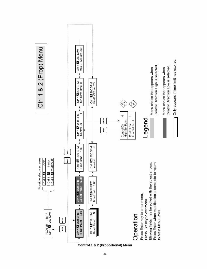
5.5 Control 1 and Control 2 Menu (FOR PROPORTIONAL CONTROLLERS) The Control 1 and Control 2 menus are separate from each other but operate in exactly the same way. Each menu provides the following independent settings: Set Point, Prop Band, Control Direction, Min SPM Rate, Max SPM Rate, Time Limit, Interlock and HOA. The top level menu status line may display the following messages: Off, Intrlck, Timeout or SPM. "Off" indicates that the output is off. "Intrlck" indicates that the output would be on but is not because of a signal from a flow switch or level switch is stopping control. "Timeout" indicates that the output has been on for longer than the maximum time programmed by the user. The SPM display shows the stroke rate of the pump. Refer to Control 1 & 2 chart on the following pages.
Hi/LoSet Point Use the arrow keys to adjust the display to read the desired set point value. Press ENTER to accept the change.
30
Control 1 & 2 (Proportional) Menu
31
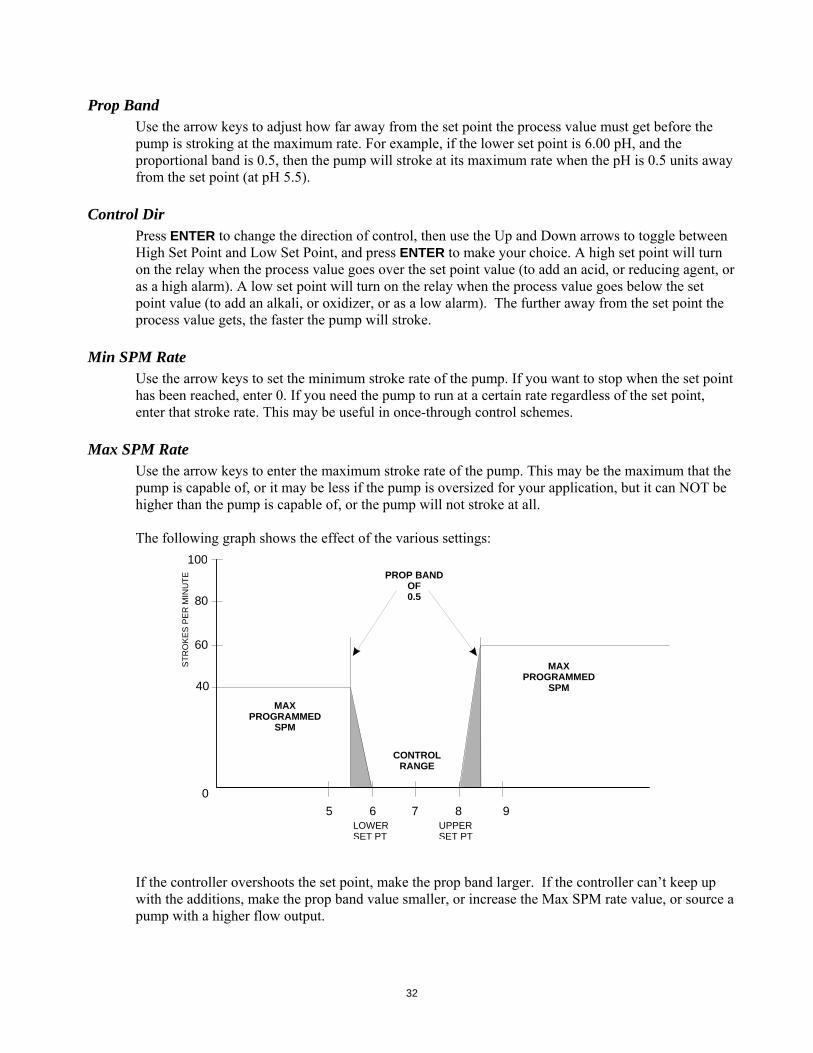
Prop Band Use the arrow keys to adjust how far away from the set point the process value must get before the pump is stroking at the maximum rate. For example, if the lower set point is 6.00 pH, and the proportional band is 0.5, then the pump will stroke at its maximum rate when the pH is 0.5 units away from the set point (at pH 5.5).
Control Dir Press ENTER to change the direction of control, then use the Up and Down arrows to toggle between High Set Point and Low Set Point, and press ENTER to make your choice. A high set point will turn on the relay when the process value goes over the set point value (to add an acid, or reducing agent, or as a high alarm). A low set point will turn on the relay when the process value goes below the set point value (to add an alkali, or oxidizer, or as a low alarm). The further away from the set point the process value gets, the faster the pump will stroke.
Min SPM Rate Use the arrow keys to set the minimum stroke rate of the pump. If you want to stop when the set point has been reached, enter 0. If you need the pump to run at a certain rate regardless of the set point, enter that stroke rate. This may be useful in once-through control schemes.
Max SPM Rate Use the arrow keys to enter the maximum stroke rate of the pump. This may be the maximum that the pump is capable of, or it may be less if the pump is oversized for your application, but it can NOT be higher than the pump is capable of, or the pump will not stroke at all. The following graph shows the effect of the various settings:
765 8 90
MAXPROGRAMMED
SPM
MAXPROGRAMMED
SPM
CONTROLRANGE
PROP BAND OF0.5
STR
OK
ES P
ER
MIN
UTE
LOWERSET PT
UPPERSET PT
40
60
80
100
If the controller overshoots the set point, make the prop band larger. If the controller can’t keep up with the additions, make the prop band value smaller, or increase the Max SPM rate value, or source a pump with a higher flow output.
32
Time Limit Use the arrow keys to set the time limit in min:sec for the output to be active, then press ENTER. If it is set for "0:00", no limit will be imposed, and the output could stay on forever.
Interlock Use the Up and Down arrows to toggle between Y(Yes) and N(No). Choosing Y means that the output will deactivate if the device attached to the controller is open. For example, if the electrode is installed in a recirculating pipe line, a flow switch that is closed if flow is sufficient and open if flow is insufficient may be installed in the line, so that if flow past the electrode stops, the controller will not pump in chemicals based on a stagnant sample. Similarly, a level switch may be attached to prevent control of an empty batch tank.
HOA Use the Left and Right arrows to move between Hand, Off and Auto. In Hand (Manual) mode, the output will be turned on immediately at the maximum programmed rate for a maximum of 10 minutes. In the Off mode, the output will be turned off indefinitely. In the Auto mode, the output turns on and off in response to changes in the process value relative to the set point. The letter inside the block on the status screen indicates which mode the output is in.
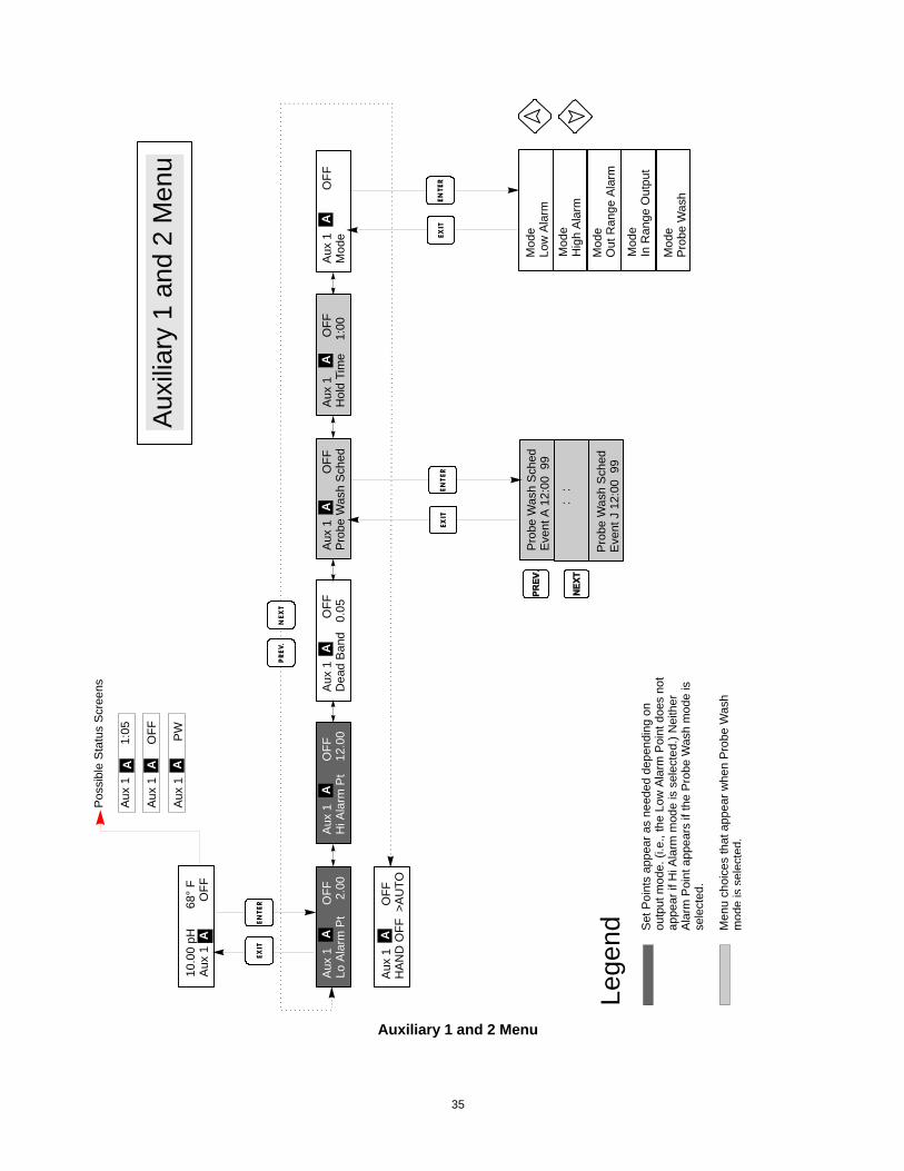
5.6 Auxiliary 1 and 2 Menu The Aux 1 and 2 relays may be configured to operate in a number of ways. They may be a low alarm, high alarm, an out-of-range alarm, an in-range output, or a probe wash. The Aux 1 and 2 menus provides the following settings, which only appear if the appropriate output mode is selected: Low Alarm Pt, High Alarm Pt, Probe Wash Sched, Hold Time, Mode. Refer to the Auxiliary 1 and 2 Menu chart. Note: When programming the controller for the first time, press ENTER to get into the submenus, then press PREV twice to get to the Output Mode menu.
Mode Press ENTER then use the Up and Down arrows to toggle between the various choices: Low Alarm Press ENTER if you want the Aux 1 relay to close if the process value goes below a certain value. High Alarm Press ENTER when this is displayed if you want the Aux 1 relay to close if the process value goes above a certain value. Out Range Alarm Press ENTER if you want the Aux 1 relay to close if the process value goes either above or below certain values. In Range Output Press ENTER if you want the Aux 1 relay to close if the process value is between two values. This is useful to open a solenoid valve if the pH/ORP has been corrected and you want to empty a batch tank.
33
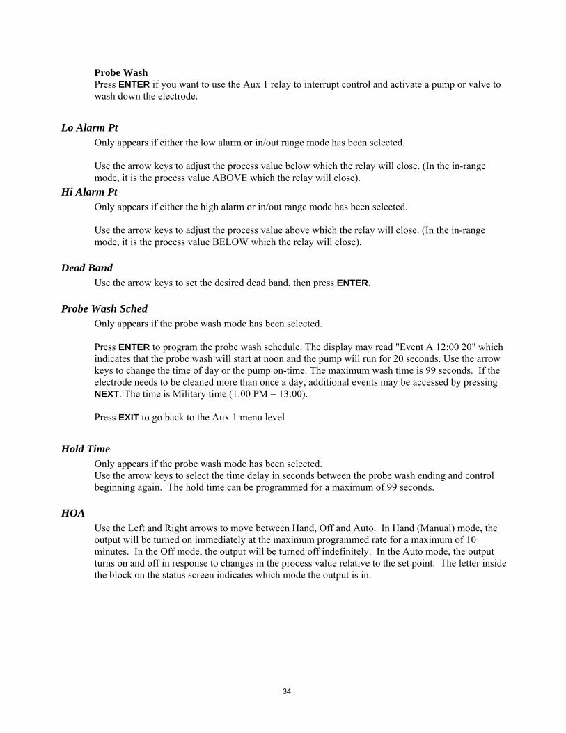
Probe Wash Press ENTER if you want to use the Aux 1 relay to interrupt control and activate a pump or valve to wash down the electrode.
Lo Alarm Pt
Only appears if either the low alarm or in/out range mode has been selected. Use the arrow keys to adjust the process value below which the relay will close. (In the in-range mode, it is the process value ABOVE which the relay will close).
Hi Alarm Pt Only appears if either the high alarm or in/out range mode has been selected. Use the arrow keys to adjust the process value above which the relay will close. (In the in-range mode, it is the process value BELOW which the relay will close).
Dead Band Use the arrow keys to set the desired dead band, then press ENTER.
Probe Wash Sched Only appears if the probe wash mode has been selected. Press ENTER to program the probe wash schedule. The display may read "Event A 12:00 20" which indicates that the probe wash will start at noon and the pump will run for 20 seconds. Use the arrow keys to change the time of day or the pump on-time. The maximum wash time is 99 seconds. If the electrode needs to be cleaned more than once a day, additional events may be accessed by pressing NEXT. The time is Military time (1:00 PM = 13:00). Press EXIT to go back to the Aux 1 menu level
Hold Time
Only appears if the probe wash mode has been selected. Use the arrow keys to select the time delay in seconds between the probe wash ending and control beginning again. The hold time can be programmed for a maximum of 99 seconds.
HOA Use the Left and Right arrows to move between Hand, Off and Auto. In Hand (Manual) mode, the output will be turned on immediately at the maximum programmed rate for a maximum of 10 minutes. In the Off mode, the output will be turned off indefinitely. In the Auto mode, the output turns on and off in response to changes in the process value relative to the set point. The letter inside the block on the status screen indicates which mode the output is in.
34
10.0
0 pH
68°
FA
ux 1
OFF
A
Aux
1
O
FFLo
Ala
rm P
t
2.00
Aux
1
O
FFH
old
Tim
e
1:00
Aux
1
O
FFH
i Ala
rm P
t 1
2.00
Aux
1
O
FFM
ode
A
ux 1
OFF
Pro
be W
ash
Sch
ed
Prob
e W
ash
Sch
edEv
ent A
12:
00 9
9
Prob
e W
ash
Sch
edEv
ent J
12:
00 9
9
Mod
eLo
w A
larm
Mod
eO
ut R
ange
Ala
rm
Mod
ePr
obe
Was
h
Mod
eH
igh
Ala
rm
Mod
eIn
Ran
ge O
utpu
t
Aux
iliar
y 1
and
2 M
enu
ENTE
REX
IT
ENTE
REX
ITEN
TER
EXIT
Lege
nd
NEX
TP
REV
.
::
Set
Poi
nts
appe
ar a
s ne
eded
dep
endi
ng o
nou
tput
mod
e. (i
.e.,
the
Low
Ala
rm P
oint
doe
s no
tap
pear
if H
i Ala
rm m
ode
is s
elec
ted.
) Nei
ther
Ala
rm P
oint
app
ears
if th
e P
robe
Was
h m
ode
isse
lect
ed.
Men
u ch
oice
s th
at a
ppea
r whe
n Pr
obe
Was
hm
ode
is s
elec
ted.
Aux
1
O
FFH
AN
D O
FF >
AU
TO
AA
AA
AA
A
Aux
1
O
FFD
ead
Band
0.
05
Poss
ible
Sta
tus
Scre
ens
Aux
1
1:05
Aux
1
OFF
Aux
1
PW
A A A
Auxiliary 1 and 2 Menu
35
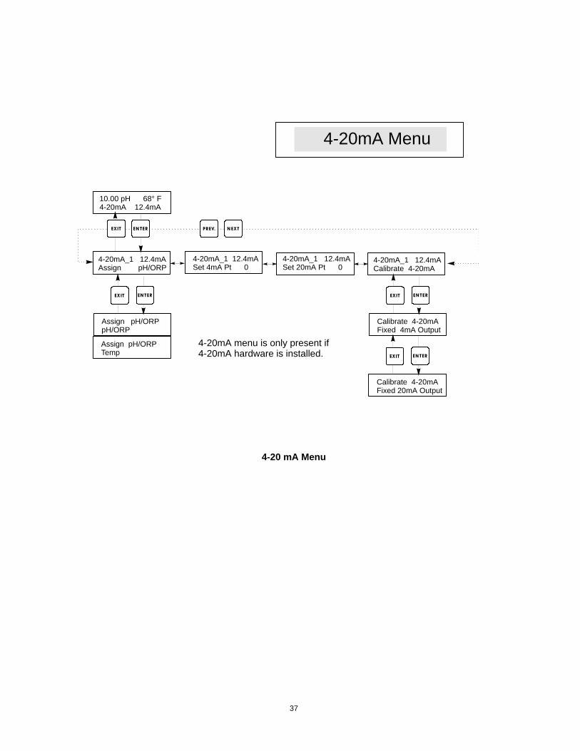
5.7 4-20 mA Menu (Optional) This menu will only appear if the optional 4-20 mA output board is installed. It is used to set the scale of the 4-20 mA output. It contains the following menu selections: 4 mA Point, 20 mA Point, and Calibrate. Note: When programming the controller for the first time, first go to the Assign Inputs Menu, then program the other menus.
Assign Inputs Press ENTER to assign the 4-20 mA output to a sensor input. Use the arrow keys to toggle between “pH/ORP” and “Temp.” Press ENTER when the desired choice is displayed.
4 mA Pt Use the arrow keys to enter the process value (in either pH units, or mV if ORP) that you want to correspond to a 4 mA output from the controller.
20 mA Pt Use the arrow keys to enter the process value that you want to correspond to a 20 mA output from the controller.
Calibrate This menu is used to calibrate instruments connected to the mA output. The 4-20 mA output is extremely accurate and stable and therefore will never need calibration. This feature allows other devices to be calibrated at the 4 and 20 mA points. Press ENTER to start the calibration.
Fixed 4 mA Out The controller will output 4.00 mA. Adjust the chart recorder or data logger per its instruction so that the process value displayed is what is expected for a 4.00 mA input.
Fixed 20 mA Out As above, except that the controller will output 20.00 mA. The design of the 4-20 mA output is such that it should never need calibration. If the mA signal is not what it should be, call the factory for service.
36
10.00 pH 68° F4-20mA 12.4mA
4-20mA_1 12.4mAAssign pH/ORP
4-20mA_1 12.4mASet 4mA Pt 0
4-20mA_1 12.4mACalibrate 4-20mA
Assign pH/ORPpH/ORP
Assign pH/ORPTemp
4-20mA Menu
EN TEREX IT
N EXTPREV.
4-20mA menu is only present if4-20mA hardware is installed.
EN TEREXIT
Calibrate 4-20mAFixed 4mA Output
Calibrate 4-20mAFixed 20mA Output
EN TEREXIT
EN TEREXIT
4-20mA_1 12.4mASet 20mA Pt 0
4-20 mA Menu
37
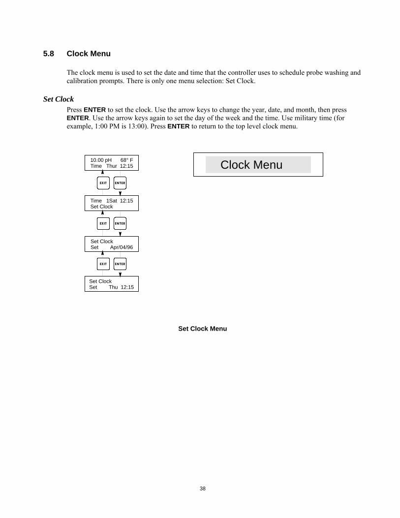
5.8 Clock Menu The clock menu is used to set the date and time that the controller uses to schedule probe washing and calibration prompts. There is only one menu selection: Set Clock.
Set Clock Press ENTER to set the clock. Use the arrow keys to change the year, date, and month, then press ENTER. Use the arrow keys again to set the day of the week and the time. Use military time (for example, 1:00 PM is 13:00). Press ENTER to return to the top level clock menu.
10.00 pH 68° FTime Thur 12:15
Time 1Sat 12:15Set Clock
Set ClockSet Apr/04/96
Set ClockSet Thu 12:15
Clock MenuEN TEREX IT
EN TEREX IT
EN TEREX IT
Set Clock Menu
38
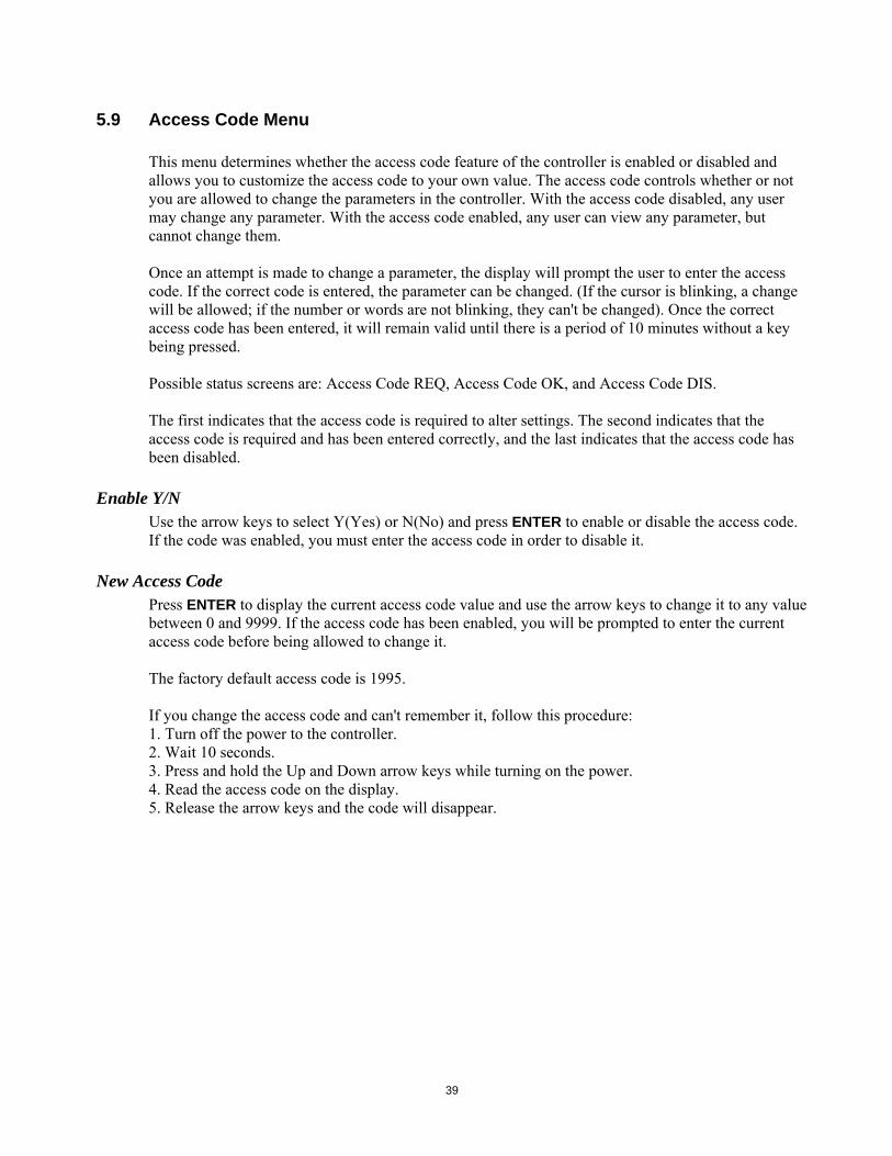
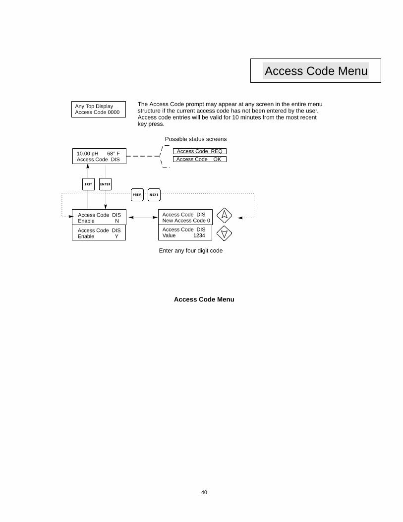
5.9 Access Code Menu This menu determines whether the access code feature of the controller is enabled or disabled and allows you to customize the access code to your own value. The access code controls whether or not you are allowed to change the parameters in the controller. With the access code disabled, any user may change any parameter. With the access code enabled, any user can view any parameter, but cannot change them. Once an attempt is made to change a parameter, the display will prompt the user to enter the access code. If the correct code is entered, the parameter can be changed. (If the cursor is blinking, a change will be allowed; if the number or words are not blinking, they can't be changed). Once the correct access code has been entered, it will remain valid until there is a period of 10 minutes without a key being pressed. Possible status screens are: Access Code REQ, Access Code OK, and Access Code DIS. The first indicates that the access code is required to alter settings. The second indicates that the access code is required and has been entered correctly, and the last indicates that the access code has been disabled.
Enable Y/N Use the arrow keys to select Y(Yes) or N(No) and press ENTER to enable or disable the access code. If the code was enabled, you must enter the access code in order to disable it.
New Access Code Press ENTER to display the current access code value and use the arrow keys to change it to any value between 0 and 9999. If the access code has been enabled, you will be prompted to enter the current access code before being allowed to change it. The factory default access code is 1995. If you change the access code and can't remember it, follow this procedure: 1. Turn off the power to the controller. 2. Wait 10 seconds. 3. Press and hold the Up and Down arrow keys while turning on the power. 4. Read the access code on the display. 5. Release the arrow keys and the code will disappear.
39
10.00 pH 68° FAccess Code DIS
Any Top DisplayAccess Code 0000
Access Code DISEnable N
Access Code DISEnable Y
Access Code DISNew Access Code 0
Access Code DISValue 1234
Access Code REQAccess Code OK
Access Code Menu
Possible status screens
The Access Code prompt may appear at any screen in the entire menustructure if the current access code has not been entered by the user.Access code entries will be valid for 10 minutes from the most recent key press.
Enter any four digit code
EN TEREXIT
N EXTPREV.
Access Code Menu
40
6.0 Maintenance The WPH control module itself needs very little maintenance. Clean the outside of the controller enclosure with a damp cloth. Do not spray down the controller unless the enclosure door is closed and latched. "Pigtails" should be protected from spray or washdown. Check the cords and cables for damage.
6.1 Electrode Maintenance The pH or ORP electrodes require periodic cleaning and calibration. These electrodes are like batteries and their voltage outputs will change with time even if they are not being used. After installation, the rate of change increases, and factors such as temperature, extremes of pH, abrasion and chemical attack will increase the required frequency of calibration. If the process solution contains oils, scale or other solids, the electrode surfaces will tend to coat, its response time will slow down and cleaning will be required. The frequency of cleaning and calibrating will vary greatly depending upon the application, the factors listed above, as well as the accuracy of control you require. The best way to determine the optimum number of days between calibrations is to remove the electrode from the process periodically (weekly in clean water applications, daily in dirty or hot applications) and check its accuracy in a buffer solution. If using manual temperature compensation, remember to change the temperature from that of the process to that of the buffer. If the accuracy of the reading is within your required tolerances, and the speed of response is good, replace the electrode in the process. If not, clean the electrode and perform a two point calibration. The method of cleaning the electrode will depend upon the coating, as well as the materials of construction of the electrode. Do not use a solvent that will attack the electrode! Care must be taken to avoid scratching the pH electrode's glass, as this will shorten its life. An ORP electrode's platinum surface may be cleaned with 600 grit silicon carbide paper, jewelers rouge or very fine steel wool. Oily coatings should be removed with a mild detergent or isopropyl alcohol. Hard scales such as calcium carbonate can usually be removed with a dilute hydrochloric acid solution. Soft coatings can be removed using a soft cloth or soft toothbrush. A two point calibration should always be performed after cleaning the electrode. Because the electrode signal is so sensitive, the condition of the cable and connectors between the electrode, preamplifier and controller is critical. Make sure that all electrical connections stay clean and dry. Never splice the cable prior to preamplification. Replace the cable if there is any sign of damage.
41
6.2 Replacing the Fuses CAUTION: Disconnect power to the controller before opening front panel! Locate the fuses on the circuit board at the back of the controller enclosure. (See figure 3.) Gently remove the old fuse from its retaining clip and discard. Press the new fuse into the clip, secure the front panel of the controller and return power to the unit. Warning: Use of non-approved fuses can affect product safety approvals. Fuse ratings depend on controller power rating. Specifications are shown below. To insure product safety certifications are maintained, it is recommended that a Walchem fuse is used.
Controller Rating F1 Walchem P/N F2 Walchem P/N
120VAC 5x20mm,0.125A,250V 102369 5x20mm,10A,125V 102432 240VAC 5x20mm,0.063A,250V 103363 5x20mm,5A,250V 102370
7.0 Troubleshooting
CAUTION: Disconnect power to the controller before opening front panel! Troubleshooting and repair of a malfunctioning controller should only be attempted by qualified personnel using caution to ensure safety and limit unnecessary further damage. Contact the factory.
7.1 Error Messages Calibration Time
This message appears to prompt you to perform the routine maintenance of cleaning and calibrating the electrode. It does not appear based upon any analysis of the condition of the electrode. The frequency of calibration is set by the user in the "Days Between Cal" menu found in the "Sensor" menu. If you do not want to be prompted to perform a calibration, set this menu to "0".
Output Timeout This error message appears if one of the control outputs has been on longer than the maximum amount of time programmed in the "Time Limit" menu found in the "Control 1" or "Control 2" menus. It is reset by answering "Yes" to the "Reset Timer" prompt that will appear. There are a number of possible reasons that the output could go on for longer than normal: Possible Causes Corrective Action 1. The process went further out of Increase time limit or reset timer. control than normal. 2. The chemical supply has run out. Replenish the chemical supply. 3. The pump or valve or supply line Repair or replace the control device. is faulty. 4. Wrong chemical is being controlled. Replace with correct chemical.
42
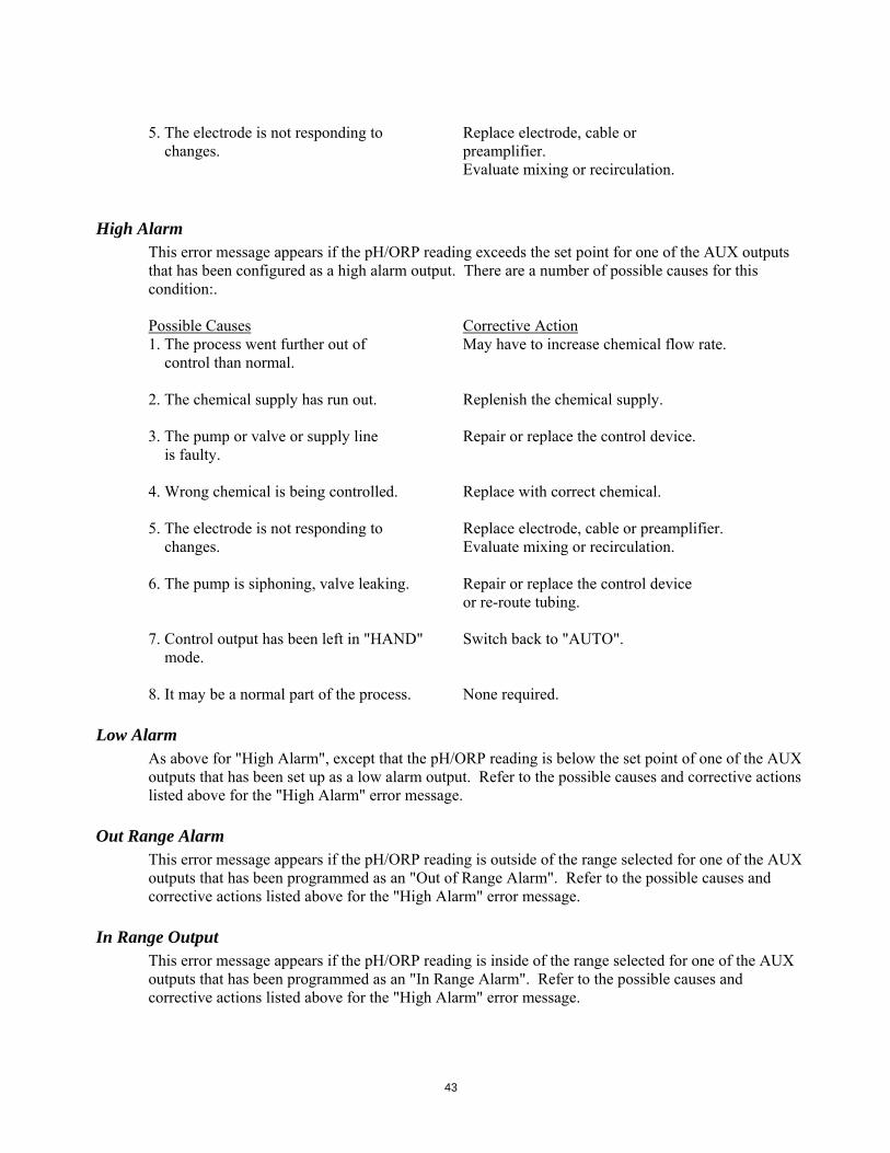
5. The electrode is not responding to Replace electrode, cable or changes. preamplifier. Evaluate mixing or recirculation.
High Alarm This error message appears if the pH/ORP reading exceeds the set point for one of the AUX outputs that has been configured as a high alarm output. There are a number of possible causes for this condition:. Possible Causes Corrective Action1. The process went further out of May have to increase chemical flow rate. control than normal. 2. The chemical supply has run out. Replenish the chemical supply. 3. The pump or valve or supply line Repair or replace the control device. is faulty. 4. Wrong chemical is being controlled. Replace with correct chemical. 5. The electrode is not responding to Replace electrode, cable or preamplifier. changes. Evaluate mixing or recirculation. 6. The pump is siphoning, valve leaking. Repair or replace the control device or re-route tubing. 7. Control output has been left in "HAND" Switch back to "AUTO". mode. 8. It may be a normal part of the process. None required.
Low Alarm As above for "High Alarm", except that the pH/ORP reading is below the set point of one of the AUX outputs that has been set up as a low alarm output. Refer to the possible causes and corrective actions listed above for the "High Alarm" error message.
Out Range Alarm This error message appears if the pH/ORP reading is outside of the range selected for one of the AUX outputs that has been programmed as an "Out of Range Alarm". Refer to the possible causes and corrective actions listed above for the "High Alarm" error message.
In Range Output This error message appears if the pH/ORP reading is inside of the range selected for one of the AUX outputs that has been programmed as an "In Range Alarm". Refer to the possible causes and corrective actions listed above for the "High Alarm" error message.
43
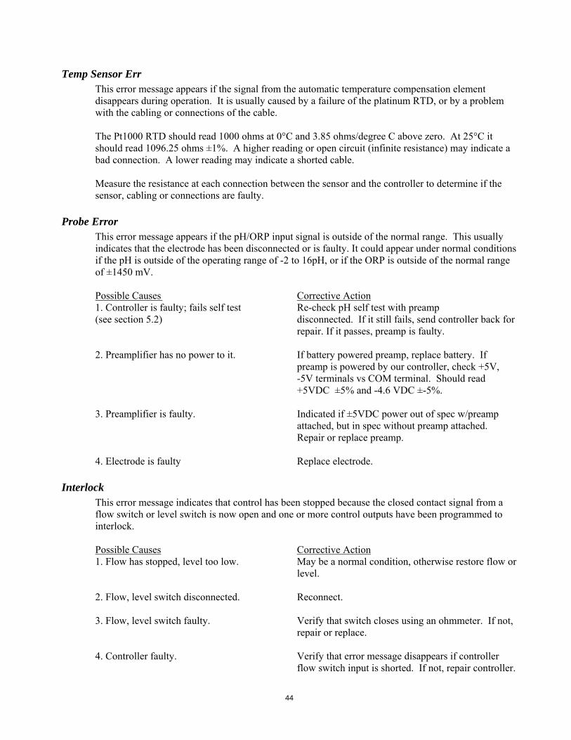
Temp Sensor Err This error message appears if the signal from the automatic temperature compensation element disappears during operation. It is usually caused by a failure of the platinum RTD, or by a problem with the cabling or connections of the cable. The Pt1000 RTD should read 1000 ohms at 0°C and 3.85 ohms/degree C above zero. At 25°C it should read 1096.25 ohms ±1%. A higher reading or open circuit (infinite resistance) may indicate a bad connection. A lower reading may indicate a shorted cable. Measure the resistance at each connection between the sensor and the controller to determine if the sensor, cabling or connections are faulty.
Probe Error This error message appears if the pH/ORP input signal is outside of the normal range. This usually indicates that the electrode has been disconnected or is faulty. It could appear under normal conditions if the pH is outside of the operating range of -2 to 16pH, or if the ORP is outside of the normal range of ±1450 mV. Possible Causes Corrective Action1. Controller is faulty; fails self test Re-check pH self test with preamp (see section 5.2) disconnected. If it still fails, send controller back for repair. If it passes, preamp is faulty. 2. Preamplifier has no power to it. If battery powered preamp, replace battery. If preamp is powered by our controller, check +5V, -5V terminals vs COM terminal. Should read +5VDC ±5% and -4.6 VDC ±-5%. 3. Preamplifier is faulty. Indicated if ±5VDC power out of spec w/preamp attached, but in spec without preamp attached. Repair or replace preamp. 4. Electrode is faulty Replace electrode.
Interlock This error message indicates that control has been stopped because the closed contact signal from a flow switch or level switch is now open and one or more control outputs have been programmed to interlock. Possible Causes Corrective Action1. Flow has stopped, level too low. May be a normal condition, otherwise restore flow or level. 2. Flow, level switch disconnected. Reconnect. 3. Flow, level switch faulty. Verify that switch closes using an ohmmeter. If not, repair or replace. 4. Controller faulty. Verify that error message disappears if controller flow switch input is shorted. If not, repair controller.
44
Check Set Points This is a normal display if you have changed the choice of sensor from pH to ORP or vice versa. The default set points for each choice is different, and will not match what you need for your application. Always select the sensor type before setting the control or auxiliary output set points.
8.0 Service Policy
The WPH Series pH/ORP Controller has a 2-year warranty on electronic components and a 1-year warranty on mechanical parts (keypad, terminal strip and relays). We stock circuit boards for immediate exchange after we have isolated the cause of the problem. Factory authorized repairs that are received by next-day-air will be returned within 24 hours. Normal priority for returns is two weeks. Out of warranty repairs or circuit board exchanges are done on a flat fee basis after the warranty is expired.
45