Embed Size (px)
DESCRIPTION
Interesante información para
Citation preview
....:.:.:.:.:.:.:.:.:.:
.:.:.:.:.:.:.:.:-:.:.:.:
WORKSHOPPROCEEDINGS
Urea-Based NPKPlant Design and
Operating AIternatives
International Fertilizer Development CenterMuscle Shoals, Alabanla USA
September 17-28, 1990
Edited byJames J. Schultz
George Hoffmeister, -
(
91-4008CIP
Library of Congress Cataloging-in-Publication Data
Urea-based NPK plant design and operating alternatives: workshopproceedings, International Fertilizer Development Center, MuscleShoals, Alabama, USA,September 17-28, 1990/ edited by James J.Schultz, George Hoffmeister.
p. cm. -- (Special publication IFDC ; SP-1S)Includes bibliographical references.ISBN 0-88090-094-61. Urea as fertilizer--Congresses. I. Schultz, J. J., 1936-
II. Hoffmeister, George. III. International Fertilizer DevelopmentCenter. IV. Title: Workshop proceedings: urea-based NPK plantdesign and operating alternatives. V. Series.TP963.4.U7U73 1991668'.6241--dc20
Acknowledgment and Thanks
The management of IFDC is grateful for the support and efforts of the largenumber of speakers and technical resource persons who freely gave of theirtime to participate in the workshop and share their experiences.
Furthermore, the workshop could not have been the success it was without thecontributions of the many delegates who participated enthusiastically in the discussions on the technical information and data recorded in these proceedings.
Finally, we are indebted to the United Nations Development Programme(UNDP) for the financial ass'istance that made the workshop possible.
International Fertilizer Development CenterMay 1991
Paul J. StangelPresident and Chief Executive Officer
Preface
The production of homogeneous granularNPK fertilizers is often surrounded by a mystique that perplexesthose looking for a simple explanation of the strangephenomena often observed when manufacturing granularNPKs. The origin of this mystique can be found in themany variables involved in the granulation process, especially the large nurrtber of raw materials and combinations(formulations) that are routinely processed in a singleplant. Add to this, variations in climatic conditions, equipment design configurations, and operator skill, and onecan quickly see why the successful pr9duction of granularNPKs is often explained more in terms of "art" thanscience and engineering.
Because granular NPKs continue to play such an important role in many fertilizer supply strategies worldwide,this workshop was organized to facilitate a better understanding of the technology and methods used for theirproduction.
Also, since urea is the most available and usually mostcost-effective source of nitrogen worldwide, this workshop
closely examined the specialized plant engineering andmanufacturing criteria required for the production ofhigh-quality NPKs using urea as the primary source ofnitrogen. Urea-based NPKs, because of their uniqueproperties, require special care in processing and storage,especially with regard to certain critical chemical, temperature, and humidity parameters. For these reasons, the useof urea in the production of granular NPKs is oftenavoided.
To help guide the workshop deliberations, a technicalbulletin was prepared describing many of the salient features that should be considered when designing andoperating urea-based NPK plants (refer to Appendix).The data contained in the technical bulletin are reinforcedand complemented by a number of invited papers describing actual commercial experience with the design andoperation of urea-based NPK plants. The technicalpapers and discussions are further supplemented by pilotplant-scale demonstrations of urea-based NPK plantdesign and operating criteria.
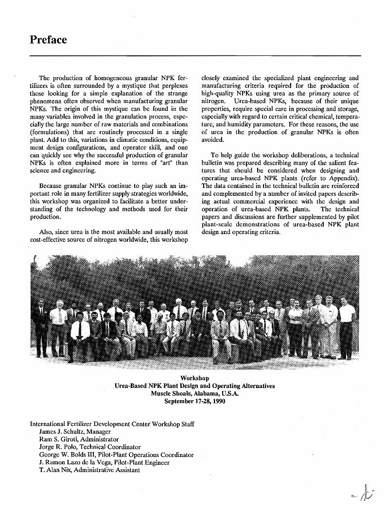
WorkshopUrea-Based NPK Plant Design and Operating Alternatives
Muscle Shoals, Alabama, U.SASeptember 17-28, 1990
International Fertilizer Development Center' Workshop StaffJames J. Schultz, ManagerRam S. Giroti, AdministratorJorge R. Polo, Technical CoordinatorGeorge W. Bolds III, Pilot-Plant Operations CoordinatorJ. Ramon Lazo de la Vega, Pilot-Plant EngineerT. Alan Nix, Administrative Assistant
Table of Contents
Selection of Fertilizers - Agronomic and Economic FactorsDennis H. Parish 1
Modified Urea Fertilizers Used in Specialty Markets and Their Potential for Agricultural CropsJohn H. Detrick 9
Nitrogen Sources for Granular NPKs- Why Use Urea?James J. Schultz 12
Experience With Production of Urea-Based High-Grade NPK FertilizersS. K Chatterjee 14
Operational Experiences With NP-NPK Granulation at Coromandel Fertilisers Limited - IndiaS. Ramadurai 21
Production of Complex Fertilizers - An Operating Experience in IndiaT. J. Joseph and T. A. Sankaran 27
Improving Productivity in NPK Granulation Plants- NAFCON (Nigeria) ExperienceT. R. Ramaswami 33
Experience With Urea-Based NPK + MgO Compound Fertilizer Production and Marketing in MalaysiaMohd. Sa//eh Bin Darns 39
Role of the Engineering Company in the Implementation of a Urea-Based NPK Granulation Project in MalaysiaLee D. Hoffman and Glen H. Wesenberg 47
Production of Urea-Based Fertilizers With Pipe-Cross Reactor Technology-TVA ExperienceB. R. Parker, M. M. Norton, and B. w: Curtis 50
Temperature Control During Agglomeration-Type GranulationJorge R. Polo 61
Dehumidification of Production Units and WarehousesJ. R. Polo 68
Fertilizer Product Conditioning Agents - Emphasis on NPKsDavid w: Rut/and 76
Storage and Handling Characteristics of Urea-Based NPK FertilizersDavid w: Rutland 82
Granulation of Fertilizers by CompactionWolfgang Pietsch 89
Compaction/Granulation of FertilizersChristian Fayard and Pascal Hervieu 99
Compaction/Granulation of Fertilizers - A Practical, Economical, and Agronomically FavorableTechnology in Guatemala
Frank A. Dalton 109Design Parameters for Bulk-Blending and Compaction/Granulation Plants
Daniel M. Alt 114The Manufacture of Fertilizers by Compaction/Granulation
Maurice O. Klein 119Pilot-Plant Demonstration of Selected Operating Parameters for the Production of Granular Urea-Based NPKs
George w: Bolds III 133Pilot-Plant Demonstration of TVA Pipe-Cross Reactor Technology for the Production of Urea-Based 17-17-17
B. w: Curtis 139Pilot-Plant Demonstration of Urea-Based NPK Granular Fertilizers Produced by the Compaction Process
J. Ramon Lazo de la Vega 141Questions and Answers-Agronomic Session 145Questions and Answers- NPK Plant Design and Operation 148Questions and Answers - Pipe-Cross Reactor Session 156Questions and Answers - Panel Discussion on Plant Operating Experience 161Questions and Answers- Compaction/Granulation Technology 166List of Delegates and Invited Speakers 176Appendix Production of Granular NPKs in Ammonium Phosphate Plants-Some Imp~rtantDifferences
(IFDC Technical Bulletin T-36)
Selection of Fertilizers - Agronomic and Economic Factors
Dennis H. Parish1
Abstract
~ 9~
Q) 8N
'roE 7
Use of a net return curve is discussed as a method forchoosing the correct fertilizer application rate to give thegreatest crop cash return per unit of fertilizer cost. Majorinternationally traded fertilizer materials are listed and theadvantages and disadvantages of these materials asnutrient sources under a variety of conditions are summarized. Bulk blending and cogranu1ation are addressedas methods for furnishing nutrients to crops.
Amount of Fertilizer to Apply
The efficiency of fertilizer use is measured in severalways by scientists.
For most agricultural situations,. the agronomic efficiency is adequate as a measure of crop response to applied fertilizer and the effectiveness of its use:
Agronomic Efficiency (kg/kg) = (Yield of salablecrop - Yield of salable crop ) divided by weight offertilizer nutrients (FN) applied
where F = fertilized crop, c = unfertilized check,and FN is plant nutrient studied.
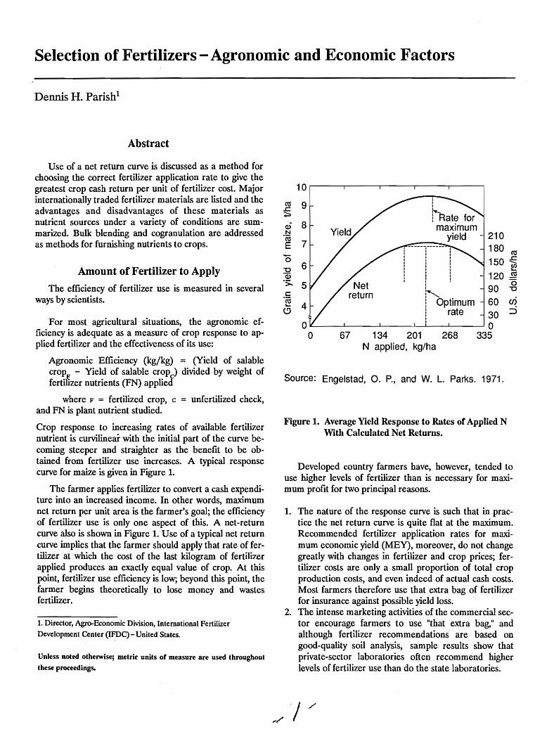
Crop response to increasing rates of available fertilizernutrient is curvilinear with the initial part of the curve becoming steeper and straighter as the benefit to be obtained from fertilizer use increases. A typical responsecurve for maize is given in Figure 1.
The farmer applies fertilizer to convert a cash expenditure into an increased mcome. In other words, maximumnet return per unit area is the farmer's goal; the efficiencyof fertilizer use is only one aspect of this. A net-returncurve also is shown in Figure 1. Use of a typical net returncurve implies that the farmer should apply that rate of fertilizer at which the cost of the last kilogram of fertilizerapplied produces an exactly equal value of crop. At thispoint, fertilizer use efficiency is low; beyond this point, thefarmer begins theoretically to lose money and wastesfertilizer.
1. Director, Agro-Economic Division, International Fertilizer
Development Center (IFDC) - United States.
Unless noted otherwise; metric units or measure are used throughout
these proceedings.
10 r------r------,----,---,------,
210-----r----- 180 CO
! 150 :E! f!?I 120 ~i (5~ 90 "'0
! Optimum 60 enI rate 30:::i
oIL--__...L..-__---L.-__--'----'-I_--1.__---1 0
o 67 134 201 268 335N applied, kg/ha
Source: Engelstad, O. P., and W. L. Parks. 1971.
Figure 1. Average Yield Response to Rates of Applied NWith Calculated Net Returns.
Developed country farmers have, however, tended touse higher levels of fertilizer than is necessary for maximurn profit for two principal reasons.
1. The nature of the response curve is such that in practice the net return curve is quite flat at the maximum.Recommended fertilizer application rates for maximum economic yield (MEY), moreover, do not changegreatly with changes in fertilizer and crop prices; fertilizer costs are only a small proportion of total cropproduction costs, and even indeed of actual cash costs.Most farmers therefore use that extra bag of fertilizerfor insurance against possible yield loss.
2. The intense marketing activities of the commercial sector encourage farmers to use "that extra bag," andalthough fertilizer recommendations are based ongood-quality soil analysis, sample results show thatprivate-sector laboratories often recommend higherlevels of fertilizer use than do the state laboratories.
Fertilizer Products
Fertilizer should be purchased only on the basis of costeffectiveness. However, product quality, i.e., granules instead of powder, and convenience (multinutrient versusstraight fertilizers) play a role in the choice. Of course,convenience carries with it a price premium which mayormay not be compensated for in terms of crop productioneconomics.
Low-analysis fertilizers are more expensive per unit ofnutrient to bag, distribute, and store than are the equivalent nutrients in concentrated fertilizers and, therefore,the international trend has been toward the use of highanalysis fertilizers.
Three factors which affect the fmal cost of fertilizerapplied in the field must be examined:
1. The technology of production.2. Handling, distribution, and storage.3. Choice of nutrient carrier (source).
Choice of Nutrient CarrierThe following major plant nutrients are needed:
1. Nitrogen.2. Phosphate.3. Potash.4. Sulfur.5. Magnesium and calcium.6. The trace elements - boron, zinc, and others.
Table 1 gives the composition of the major internationally traded fertilizers. The frrst point to be made fromTable 1 is that, if sulfur is a required nutrient, AS can beconsidered as a high-analysis fertilizer. If, however, sulfuris not needed, AS is a low-analysis fertilizer that cannotcompete with urea in terms of delivered cost of nitrogen.Phosphate rock (PR), single superphosphate (SSP), andtriple superphosphate (TSP) also contain calcium, whichmay be needed as a plant nutrient; however, where soil calcium is low, the use of small dressings of local limestonewould appear to be the most logical way to correct thisproblem.
a. Sulfur content may vary depending upon acid-to-rock ratio.
Table 1. Major Internationally Traded Fertilizers
TotalNutrient Content, %
% by Weight N + P20S. N P20S K20 + K20 S
Technology of ProductionModern fertilizer technologies are very cost effective
and their products are cheap and readily available to theinternational trade. Importation of fertilizers is thereforeoften the most efficient route. Local production of fertilizers should only be encouraged where it will be competitive with imported fertilizers. Furthermore, until largefertilizer markets have been built up, production unitswith a low level of capital investment and a flexible operation should be the prime objective.
Handling, Distribution, and StorageEfficient handling, distribution, and storage of fer
tilizers are essential if costs are to be kept as low as possible. With the tremendous distances and generally poorhinterland infrastructure, many developing countries faceenormous problems. Inefficient logistics not only increasefertilizer costs but can also reduce the efficiency of its use;fertilizer which arrives late or not at all, or is of the wrongkind, can reduce anticipated crop yields and destroy thecarefully nurtured confidence of the farmer in relying oninput supplies.
Product
Ammonium chloride 26 26Ammonium nitrate 34 34Ammonium sulfate 21 21Urea 46 46Monoammonium phosphate 11 52 63Diammonium phosphate 18 46 64Phosphate rock - 30-34 30-34Potassium chloride 60 60Potassium sulfate 50 5020-10-10 20 10 10 4015-15-15 15 15 15 4520-20-0 20 20 40SSP 20 20TSP 46 4616-20-0 16 20 36
24
18
9-13Depending
uponprocess
Costs. associated with fertilizer handling, distribution,and storage are ver.y high. For example, the f.o.b. cost ofammonium sulfate (AS) may be doubled by the time thefertilizer reaches the farmer. Such doubling of the f.o.b.cost per bag of fertilizer delivered to the farmer meansthat only products with a high nutrient content can be considered where transport distances are long.
2
Source: IFDC, 1985.
Nitrogen (N)The major sources of nitrogen are anhydrous
ammonia, ammonium nitrate, ammonium sulfate, ammonium chloride, urea, and various nitrogen-containing
Source: IFDC, 1986.
Table 2. Potential Acidity of Nitrogen Fertilizers
a. Amount of pure calcium carbonate (CaCOJ) required to neutralizeacidity produced by fertilizer in soil.b. Other similar products are calcium ammonium nitrate, nitro-lime,and nitro-chalk. Various means of production result in variations ingrade and potential acidity.
1. Continuous use of N fertilizers (particularly at highrates) decreases soil pH.
2. The lower pH is caused by lowering of the calcium andmagnesium status of soils and is accompanied by anincrease in extractable aluminum and sometimesmanganese.
1.81.81.85.25.1o
-1.3-1.8
Potential Aciditl
1.480.840.591.101.28o
-0.20-0.29
N(%)
Fertilizer
Anhydrous ammonia 82Urea 46Ammonium nitrate 33.5Ammonium sulfate 21Ammonium chloride 25Ammonium nitrate Iimestoneb 20.5Calcium nitrate 15Sodium nitrate 16
In actual practice, these potential values are not observed in soils. Adsorption by plants modifies acidity tothe extent that cations or anions are preferentially takenup by plants. The final acidity from a fertilizer in a particular zone of soil develops only after residual salts areremoved from that zone by leaching. Research has confirmed the following effects:
Nitrification of ammonium forms of fertilizer (changefrom ammonium to nitrate) produces hydrogen ions whichcan contribute to soil acidity. Each kilogram of N potentially requires 1.8 kg of calcium carbonate to neutralizethe acidity. Furthermore, the associated anions of ammonium fertilizers give rise to additional acidity due toresidual anions. Potential acidity from several nitrogen fertilizers is shown in Table 2. Ammonium chloride and ASare the most acidifying because of the contribution of sulfate and chloride to potential acidity. Products, such as calcium, potassium, and sodium nitrate, have positive limingvalues because of their basic cations.
tropical soils where crop intensification and increased useof N fertilizers are occurring. The acidifying effect of N fertilizers is of greater consequence in sandy soils of lowbuffering cation exchange capacity (CEC) than in soils ofhigher CEC and, therefore, soil acidification is potentiallya serious problem in many areas.
N Loss - Ammonia volatilization loss is another potential limitation on the use of urea. When urea is incorporated into soil, the free ammonia formed uponhydrolysis ionizes with water and the ammonium ion isheld by the cation exchange complex of soil. However,when urea is left on a moist soil surface, especially with anupward flow of water, hydrolysis to ammonia is rapid, anda portion of the free ammonia escapes to the atmosphere.Rainfall in sufficient quantity to move the urea into thesoil would minimize this ammonia volatilization loss,whereas very light rainfall, just sufficient to lead tohydrolysis of urea, followed by drying conditions wouldcause large ammonia volatilization losses. Reported dataindicate that up to 80% of urea applied on a dry soil surface remained as urea for 14 days even under highhumidity and nightly dews. The varying rainfall patternsfollowing urea application are partly responsible for theerratic results reported for the relative efficiency of ureawhen surface applications have been used.
A brief summary of findings of many trials indicatedthat when urea was incorporated into the soil within 1 dayfollowing application, either through water additions or tillage, it was as effective a source of N as AS or ammoniumnitrate (AN). When urea was broadcast and left on thesoil surface, the average of many trials for upland cropsand paddy rice showed that it was slightly inferior to AS orAN; however, it was significantly inferior in some trials. Inthe latter cases the poor performance was generally attributed to ammonia losses. Empirical research data confirm the high potential losses of ammonia from surfaceapplications of urea from both upland soils and water surfaces of paddies. Where the pH is greater than 7.5,ammonia losses may also .occur from surface-appliedammonium sulfate.
Effects of N Fertilization on Soil Properties - A majorconcern of many agriculturists is the acidification of
Toxicity - The toxicity of free ammonia, formed by thehydrolysis of urea in soil, is a potential crop hazard following improper use of urea. In most warm, moist soils, ureahydrolysis is rapid, often within 1 week. This rapidhydrolysis can give rise to high concentrations of free ammonia near the urea placement sites. Because of thetoxicity of free ammonia to plants, it is recommended thaturea never be placed in close contact with seeds or in contact with the base of young plants.
The agronomic appropriateness of urea as a fertilizeris discussed under the following headings.
compound products. Although all straight nitrogen fertilizers are effective fertilizers if correctly used, they arebeing replaced in world trade by urea because of itsdelivered cost advantage.
3
3. AS has a greater depressant effect upon soil pH thandoes urea or calcium ammonium nitrate (CAN). Thelatter two sources of N result in similar effects on soilpH, even though· theoretically urea has the greaterpotential acidity.
With the ever-increasing soil acidity problem, somemeans of applying calcium carbonate to soils should bedeveloped. Ground limestone possibly could be cogranulated with urea, but it would likely be less expensive todevelop an agricultural limestone industry to supply limingmaterials. The widespread use of liming materials has often been achieved only through the use of subsidies andintensive extension activities.
Phosphate (P)Internationally traded P fertilizers are ground PR,
MAP, DAP, the whole range of NPK materials, TSP, SSP,and ammonium phosphate/sulfate. These materials aredescribed in Table 1. Many countries must import all oftheir P needs; under these conditions the economic argument for high-analysis material, as with N fertilizers, outweighs the opportunity for some flexibility in the selectionof imported P products.
ssp-SSP was, by far, the most important P fertilizerfor over 100 years and is still an important fertilizer. It canbe produced by uncomplicated processes and equipment,and its effectiveness as a source of P is unquestioned.Also, it contains calcium and sulfur, which may contributeto soil fertility, and sometimes trace elements originatingfrom the PRo Its main disadvantage is its low analysis,about 16%-22% P20S. Because of its low analysis, it isusually made in small plants located in the market area.SSP inay be a good choice for developing countries (andfor some developed countries) that have either sulfuricacid or PR or both. This is especially true when both Pand sulfur are needed for good crop growth, which is thecase in many parts of the world.
TSP, MAP, and DAP-Based on phosphoric acid,these products are essentially sources of water-solublephosphate and are therefore agronomically equivalent;their popularity over SSP is due to their lower costs perunit of P delivered·at the farm.
Nitrophosphates-These products are based on nitricacid. They vary in composition and in the water solubilityof the P they contain. Again cost per unit of agronomicallyeffective P delivered at the farm should be the basis forselection.
Phosphate Rock - Direct application of fmely groundPR may be the least expensive way to supply P to crops inlarge areas of the world. The practice is well established inseveral developed and developing countries; it is estimated
4
that about 5% of the world's P fertilizer use is supplied bydirect application of PRo Its use is especially attractivewhen indigenous PR is available; however, use of imported rock may be economical in some cases. The· bestresults are obtained on well-watered acidic soils and withrelatively reactive phosphate rocks.
The advantages of using ground PR for direct application are as follows:
1. Low cost, especially if indigenous rocks are used.2. Low capital investment.3. Low requirement for technical skill.4. Small energy requirement.5. Suitability of rocks unsuitable for chemical processing
(high-carbonate or high-chloride rocks, for example).6. Avoidance of long delays for constructing processing
equipment.7. Low importance of economy of scale and capacity
utilization.8. Supply of calcium and sometimes other nutrients in
addition to P.
The practice has certain distinct disadvantages that cannot be ignored. The most notable of these are thefollowing:
1. The P content in PR often is considerably less thanthat found in high-analysis conventional phosphates;thus, its competitiveness for markets at increased distances from the mine site is limited.
2. Different PRs vary considerably in chemical reactivity,and their agronomic effectiveness is strongly influenced by soil, crop, and climatic conditions.
3. The proble~of the dustiness of powdered phosphaterock has generally been overstated. It should be notedthat in Malaysia, where agricultural workers are relatively well paid, powdered PR spread by hand is amajor fertilizer.
Many farmers in the United States started P fertilization frrst by using ground rock, and the annual U.S. consumption rose to more than 1 million tonnes in the 1950s.Later, the consumption declined when high-analysis,granular, soluble phosphates, such as DAP, became available from Florida and freight cost increases made theproducts competitive with ground rock.
Partially Acidulated Phosphate Rock· (PAPR) - PAPRhas been produced in several European countries and inBrazil and is still being produced in sizable quantities in afew countries. Acidulation of ground PR with about 50%of the sulfuric acid that is required for SSP gives a productthat can contain about 23% total P20s, of which aboutone-half is water soluble and hence readily available; theremainder will behave like the rock from which it is made.
Under proper conditions, the reaction is rapid and complete, and the product does not require curing. Theproduct has the obvious advantages of lower cost due tosaving of sulfuric acid and higher analysis than SSP. Also,it is a good source of sulfur where that element is deficient, and the S:P20S ratio is close to that required formost crops.
Summary of P Research Results - The followinggeneralizations on P selection illustrate the results ofrecent research.
1. Both water-soluble fertilizers and citrate-soluble Pfertilizers may be said to be available to plants, butthere can be considerable differences in cropresponse under different circumstances.
2. For absolute maximum yields, regardless of soil orannual food crop to be grown, highly soluble Psources are the fertilizers of first choice. For cropsgrown on acid soils under the typical constraints ofdeveloping countries, water solubility is lessimportant.
3. Citrate-soluble phosphates low in water-soluble Pand unacidulated PR with a hi.gh chemical reactivitymay be as effective as water-soluble sources on longseason crops.
4. PR is generally most effective on acid soils with lowP-retention capacity.
5. In cases where P demand of the crop exceeds thecapability of an unacidulated source to supply P orwhere the P-retention (fixation) capacity is so greatthat the rock is incapable of raising the concentrationof P in soil solution to an adequate level, sourceswith 50% of the total P in water-soluble form havegenerally been found to be essentially equal in effectiveness to the completely soluble forms.
6. Short-season, fast-growing crops and those withrestricted root systems generally require a fertilizercontaining a high proportion (50%+) of watersoluble P for maximum yields. Such crops frequentlygive only limited response to applications of slightlycitrate-soluble materials such as PRo This is primarilytrue for soils that are low to medium in available P.
7. When low rates of P are to be applied, the greatestcrop response and most efficient use of P will beachieved by band application adjacent to the seed ortransplant. In such cases 50%-60% of the P shouldbe in the water-soluble form.
8. Water solubility increases in importance where soilmoisture is limiting.
9.. With phosphates of high water solubility, effectiveness increases with an increase in particle size.
5
10. For row or band application, highly water-solublesources of P combined with ammonium-N are mostuseful.
11. In general, when the degree of water solubility of theP and the granule size of fertilizers are comparable,there will be little difference in the availability of thefertilizers, regardless of the method of manufacture.
12. One of the economic factors influencing P use dealswith residual P. Most economic analyses as well asgovernment policies fail to put a value on residualP.As a result, much confusion prevails on this subjectwhich, in turn, affects P use. Farmers treat P as anannual cost and apply it accordingly. However, only5%-15% of the fertilizer P applied to the soil isrecovered by the first crop. The remaining P is heldin the soil and added to a P pool, which is graduallyavailable to subsequent crops. As a result, annualadditions in excess of crop removal will graduallybuild P fertility in the soil. The speed with which thisfertility is built will depend on a host of factors, including the rate of P20S application in relation toremoval and the P-retention characteristics of thesoil.
Potash (K)Potassium chloride is the standard potash fertilizer. It
contains the equivalent of 60% K20 and thus is considereda concentrated source of potash. Because of the low costof production, potassium is the cheapest commerciallyavailable nutrient and is simple to use.
Sulfur (S)Recent experience has shown sulfur deficiency to be.
more widespread than was thought. Poor crop residuemanagement and the use of sulfur-free fertilizers aggravate the situation. Accurate diagnosis is the key to theremoval of yield limitations due to sulfur deficiency. Formany of the crops of importance, diagnostic criteria arenonexistent or lacking in precision. The change to moreconcentrated fertilizer, and particularly from AS to urea,is a cause for concern. Researchers should carefully examine the possibility that at least a modicum of sulfur isneeded in all compound fertilizer formulations in order toprevent loss of yield should sulfur, in fact, be limiting. ASand 16-20-0 are good sources of sulfur, as are SSP andPAPR. Elemental S can also be used directly or incorporated into fertilizers. Sulfur added to urea is a newproduct.
Magnesium (Mg)This element is not usually a cause for concern unless
high levels of potash are used, which can induce a
deficiency of magnesium. The ideal source of magnesiumfor acid tropical soils is dolomite. Kieserite is a more expensive source of magnesium.
Calcium (Ca)Deficiencies of calcium, e.g., on groundnuts in Nigeria,
cause yield loss. Calcium-containing fertilizers or groundlimestone cure the problem.
Trace Elements (B, Cu, Fe, Mo, Mn, Zn)There is a wide range of products available as salts,
oxides, or chelates. These can be applied to the soil, mixedwith fertilizers, and dusted or sprayed onto plants. Traceelements are required in such small quantities that theymay present a problem to the fertilizer formulator. Themajor word of caution is that at high levels some can betoxic to plants; boron, particularly, can accumulate quitequickly to toxic levels.
Mixed Fertilizers (NPs and NPKs)Crops need many nutrient elements for optimum
growth, but fertilizers containing N, P, and K account foralmost all the world's supply. However, with the use ofhigh-analysis, low-sulfur fertilizer, sulfur is becoming increasingly important and supplementary magnesium isused on many plantation crops so that significant tonnageof fertilizers containing these two nutrients is used. Although local deficiencies of trace elements also occur,total tonnages of trace elements used are relatively small.
Choosing the Most Appropriate FertilizerPersuading the farmer to use the correct rate and type
of fertilizer nutrients on his crops is a problem that exercises the minds and resources of the governments of manydeveloping countries. The problem of balanced fertilization is two-sided - many fertilizer recommendations madein developing countries are not site specific and are basedon experiment station trials, which often give much higheryields than the average farmer can achieve; conversely,many farmers do not fertilize in an optimum way even fortheir lower yields. When fertilizer recommendations andactual farmer use practices do not match, it is essentialthat the research agronomists, the fertilizer marketer, theextension staff, and the farmers be involved in identifyingthe reasons for the disparity and in developing correctivemeasures. Cash crop production input credit programsthat give the farmer a package of desirable practices, including specified quantities and types of fertilizer, ensurethat the farmer at least acquires the officially recommended fertilizer. Such package credit programs havebeen widely used with success by the crop monopoly organizations. In India, government control orders requirefertilizer retailers to stock· both P and potash (KCl) at aspecified level in relation to their sales of N. With a free
6
market situation, it is necessary to educate the farmer tomaximize his returns by using the correct rates and ratiosof fertilizer nutrient.
When all the nutrients to be used in an agriculturalarea come together at one point, whether by port,railhead, or road, then the need for and desirability ofproducing complex (NPK) fertilizers at that point shouldbe examined. A case can be made for anyone of the following three alternatives:
1. Continuing to move products as separate and distinctmaterials.
2. Processing the incoming nutrients to makehomogeneous granular complex fertilizers.
3. Mixing the incoming nutrients using current bulkblending technology.
The fmal choice of technology will depend on the localsituation. Some countries, Cameroon for example, havehad the misfortune to have invested in a granulation plantat the wrong time in the development of fertilizer use.Low sales and high production costs led to early closing ofthis plant.
Granular complex fertilizers have achieved greatpopularity among the small farmers because of thereliability of the products. Blue, green, or red high-qualityfertilizer granules cannot be counterfeited by backyardoperators; this fact, together with the strong sales pitchthat "every granule contains the same nutrients as everyother granule," has certainly attracted a loyal clientele forthe producers of granular fertilizers. Complex fertilizerscontinue to be of great interest for upland crop productionto the high-value cash crop grower, but they have continued to lose the market share to the bulk-blendedfertilizers.
There is a general trend toward manufacturing concentrated fertilizers in large plants at or near the source ofthe raw materials and shipping the products in bulk to consuming areas. This trend is likely to continue. Bulk shipment of fmished products requires reasonably free-flowingmaterials so that products, such as urea, DAP, and KCIcan be rapidly loaded and unloaded from ships, barges,and railcars. Therefore, these materials are increasinglyproduced in granular form to avoid serious caking. Theavailability on the world market of an abundance of thesehigh-analysis, reasonably priced materials will encouragebulk blending because blending adds very little to the costof bulk shipment, storage, handling, bagging, and distribution. Although blending has long been popular in theUnited States and Canada, there is a growing trend for thepractice to spread to other-countries.
On the typical developing country farm of 1-2 ha andindividual plots of about Y4 ha, the farmer will use handspreading. In this situation, use of the cheapest solidmaterials, such as urea, DAP, and KCI, is probably themost economic route; however, because it is also the onethat relies most heavily on the farmer's knowledge of thenutrients needed, the relevance of the next lowest costsolution, that of bulk blending, should be evaluated.
Bulk blending is attractive as an alternative to handlingstraight N, P20S, and K20 through the distribution system,but the risk exists that the nutrient ratios delivered to the\system will be excessively tailored. Only a few majorgrades should be made and, even then, in practice farmerswill probably find themselves being forced to take gradesnot totally adequate for their need because of deficienciesin the marketing system.
Although bulk blending is a simple process, there areelements of technology that should not be ignored. Production of satisfactory blends in developing countries requiresmore care than in cooler, less humid climates. Unlike thecommon practice in the United States of mixing and applying blends on the same day, in most countries the blendsmust be bagged, stored, and transported through the distribution system to the farmer. Thus, the blends must havegood physical properties, and the bags must have
7
adequate strength and resistance to moisture penetrationif the products are to reach the farmer in usable condition.
The addition of trace elements to bulk blends is difficult and in areas where a complex mix of plant nutrientsis required, the use of complex fertilizers as ingredients ofthe bulk blend should be considered.
Conclusions
Although inadequate or badly distributed rainfallreduces crop yields, low soil fertility is the majorcontrollable constraint to crop production. The recyclingof organic matter and the use of leguminous crops canhelp, but fertilizers are essential over large areas. Fertilizers are expensive, and the form, rate, and time of application and placement must be optimized if their use isto be profitable. Plantation-type crops and small farmercash crops, such as high-Yielding varieties of rice, wheat,maize, and cotton, bring economic benefits when correctlyfertilized. With the traditional cereals and root crops, factors other than the low soil fertility often reduce thefarmer's interest in fertilizer; the inability to turn a sureprofit from fertilizer use is the principal factor.
The choice of fertilizer for sale to farmers should bemade on the basis of cost per unit of agronomically effective nutrient applied in the field. As a nitrogen source,urea is extremely competitive with other forms, and inAfrica, where transport and distribution costs are high, thehigh analysis of urea (46% N) makes it the rational choice.For phosphates, the materials DAP and MAP are currently extremely competitive, again particularly becausetheir high analysis reduces transport and distribution cost.PR, which is the cheapest P source f.o.b., is often not competitive with DAP when evaluated on a delivered cost tothe farm. Large-scale soil rehabilitation projects shouldconsider bulk PR as a P source; under these conditions itwould then be competitive because it would be muchcheaper delivered in the field than would bagged PRo Forpotash, the situation is quite simple. Potassium chloride isused where chloride is not harmful to crop growth orquality; otherwise, potassium sulfate is used. Sulfur iswidely deficient and can be supplied easily as AS or asSSP and, of course, as elemental S. Trace elements areusually applied as salts, but organic compounds, Le.,"chelates" are available for special use. Boron is widelyused in Africa in the form of sodium borate.
Multinutrient fertilizers, either as homogeneousgranules or as bulk blends, have a role to play, but the multinutrient ratios produced must be restricted in numberand selected to match the needs of significant numbers offarmers.
Fertilizer costs could be reduced by improvedproducts, production techniques, handling, and use. Only acarefully integrated fertilizer sector can help nations stimulate farmer use of fertilizers and increase national benefitsfrom their use.
Some developing countries have a tendency to neglectthe quality of both straight and mixed fertilizers and theirpackaging. It is unfortunate that many countries appearwilling to spend huge sums of money on manufacturingfacilities but fail to provide adequate facilities to ensurethat products are of good quality and can be delivered tofarmers in usable condition.
Strong and enforceable fertilizer legislation to ensurethat farmers receive what they are paying for is an absolutely essential component of all sound fertilizermarketing systems.
8
Bibliography
Diamond, R. B. 1983. "Agronomics of Urea Usage,"IN Nigeria Fertilizer Marketing Study, IFDC, MuscleShoals, Alabama, U .SA.
Engelstad, D.P., and W. L. Parks. 197t "Variability andOptimum N Rates for Corn," Agron. Journal, 63:21-23.
Engelstad, D.P., and G. L. Terman. 1980. "AgronomicEffectiveness of Phosphate Fertilizers," IN The Role ofPhosphorus in Agriculture, F. E. Khasawneh et al.(eds.), American Society of Agronomy, Madison,Wisconsin, U.SA.
Modified Urea Fertilizers Used in Specialty Markets andTheir Potential for Agricultural Crops
John H. Detrick!
Abstract
Methods of modifying urea to control the rate ofnitrogen release in the soil are reviewed. Currently usedmethods include (1) reaction to form slowly soluble compounds such as urea-formaldehydes, (2) coating urea withsulfur, and (3) coating urea with organic polymers. Because of high costs and less than optimum time/releasecharacteristics, none of- these products have found acceptance for large-volume agricultural crops. However, a newcoating process, now under development, results in the insitu formation of an ultrathin organic polymer coating,with resultant lower coating costs and more favorablerelease characteristics. It is expected that urea coated inthis manner may be economical for application to someagricultural crops.
Introduction
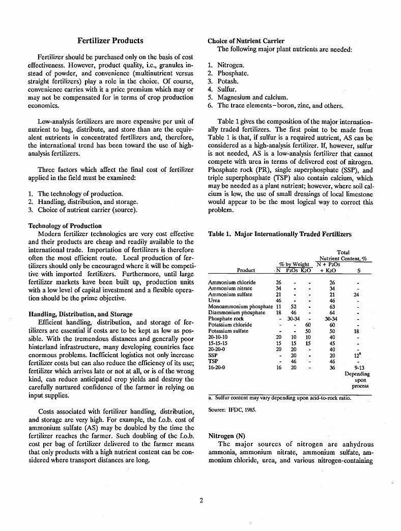
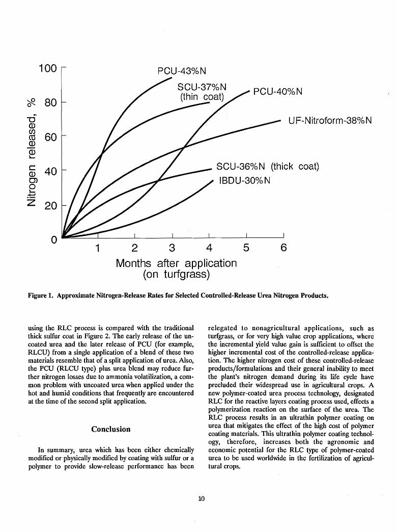
Modified solid urea particles used as controlledrelease nitrogen are divided into two categories: (1) chemically reacted urea products such as solid ureaformaldehyde and (2) physically coated urea particles suchas sulfur-coated urea (SCU) and polymer-coated urea(PCU). The principal market application for thesecontrolled-release urea nitrogen (CRUN) formulations isfor noncrops, such as golf course turfgrass, whereturfgrass quality considerations are paramount. A smallermarket for CRUN products exists in high-value crops,such as nursery ornamentals and fruit/vegetable crops,such as strawberries/peppers, where the high value of theincremental yield increase offsets more than threefold theincremental cost of the controlled-release fertilizer whichcaused the yield gain. Typical nitrogen-release rates for anumber of CRUN products are shown in Figure 1.
Potential for Modified Urea Products
The potential for using CRUN products in agriculturalcrops of relatively low value per hectare will be greatest
1. Manager, Technology and Market Development, Pursell Industries
Division, Parker Fertilizer Company, Inc. - United States.
9
when (1) the nitrogen demand by the plant during its lifecycle can be met by the nitrogen released from a blend ofuncoated soluble urea and a controlled-release ureanitrogen product and (2) the CRUN product is producedrelatively close to the site of its use by a productionprocess that is relatively simple, safe, and low cost. The incremental cost per hectare of the CRUN application mustbe offset by the value of the incremental yield gain abovenormal yields expected through standard fertiliZer practice. Usually, the minimum acceptable incremental valueto incremental cost ratio is 3 to 1.
The two most commonly used modified urea products,sulfur-coated urea and urea-formaldehyde, generally aredeficient for use in agricultural crop applications because(1) the processing is not simple and has a high capital costfor production and (2) the nutrient-release proftle is curvilinear as a consequence of too much early release (whichonly needs to be supplied by the soluble portion of theblend) and incomplete release during the plant's life cycledemand for nitrogen. Since, on a contained nitrogen basis,the cost of sulfur-coated urea is two to three times that ofuncoated urea, and urea-formaldehyde nitrogen costs aregreater still, the economical use of these products inagricultural crops is unlikely. The wide use of polymercoated urea for agricultural crops is even more unlikely,since the use of polymers as coatings can be as much as 20to 30 times more costly than the use of sulfur as a coatingmaterial. Also, current polymer-coating technologies donot provide the required degree of release control whenapplied onto the urea at the ultra-thin coating level that isnecessary to achieve a low percentage of applied coatingthat would compensate for the higher polymer materialcost.
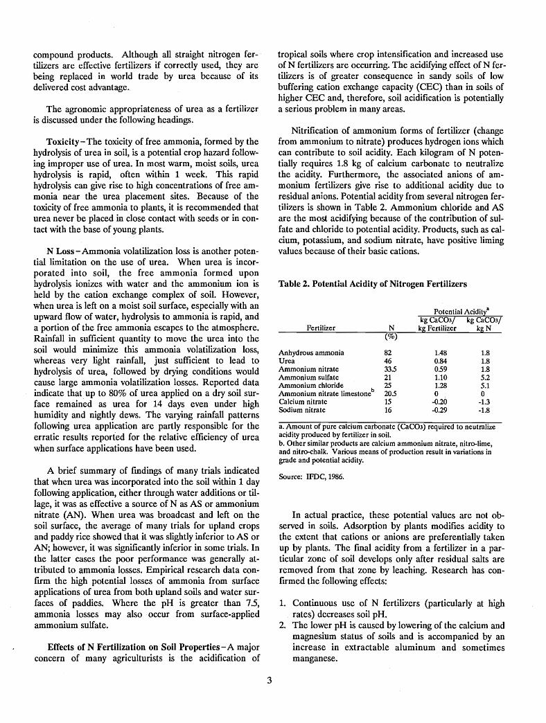
Recently, a new process has been developed wherecopolymerization of applied liquid monomers occursdirectly on the granule surface during the coating process.A series of sequentially applied liquid monomer layersreact, polymerizing in place on the granule, to form atough, durable, ultrathin polymer membrane coating.Urea coated by this reactive layers coating (RLC) processhas minimal initial release following application, therebypermitting increased use of low-cost uncoated urea in agranular blend with PCU. The ultrathin coating achieved
62 345
Months after application(on turfgrass)
1o
100 PCU-43%N
SCU-37%N
eft 80(thin coat)
...."0 UF-Nitroform-38%NCDen
60coCDCD~
c 40 SCU-36%N (thick coat)CD0> IBDU-30%N0~
:!:::Z 20
Figure 1. Approximate Nitrogen-Release Rates for Selected Controlled-Release Urea Nitrogen Products.
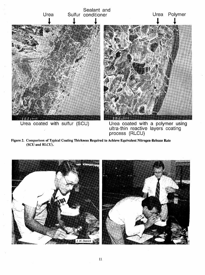
using the RLC process is compared with the traditionalthick sulfur coat in Figure 2. The early release of the uncoated urea and the later release of PCU (for example,RLCU) from a single application of a blend of these twomaterials resemble that of a split application of urea. Also,the PCU (RLCU type) plus urea blend may reduce further nitrogen losses due to ammonia volatilization, a common problem with uncoated urea when applied under thehot and humid conditions that frequently are encounteredat the time of the second split application.
Conclusion
In summary, urea which has been either chemicallymodified or physically modified by coating with sulfur or apolymer to provide slow-release performance has been
relegated to nonagricultural applications, such asturfgrass, or for very high value crop applications, wherethe incremental yield value gain is sufficient to offset thehigher incremental cost of the controlled-release application. The higher nitrogen cost of these controlled-releaseproducts/formulations and their general inability to meetthe plant's nitrogen demand during its life cycle haveprecluded their widespread use in agricultural crops. Anew polymer-coated urea process technology, designatedRLC for the reactive layers coating process used, effects apolymerization reaction on the surface of the urea. TheRLC process results in an ultrathin polymer coating onurea that mitigates the effect of the high cost of polymercoating materials. This ultrathin polymer coating technology, therefore, increases both the agronomic andeconomic potential for the RLC type of polymer-coatedurea to be used worldwide in the fertilization of agricultural crops.
10
Urea
~
Sealant andSulfur conditioner
~ ~
Urea
~
Polymer
~
I
Urea coated with sulfur (SCU)Z 1 I
Urea coated with a polymer usingultra-thin reactive layers coatingprocess (RLCU)
Figure 2. Comparison of Typical Coating Thickness Required to Achieve Equivalent Nitrogen-Release Rate(SCD and RLCU).
11
Nitrogen Sources for Granular NPKs - Why Use Urea?
James J. Schultz1
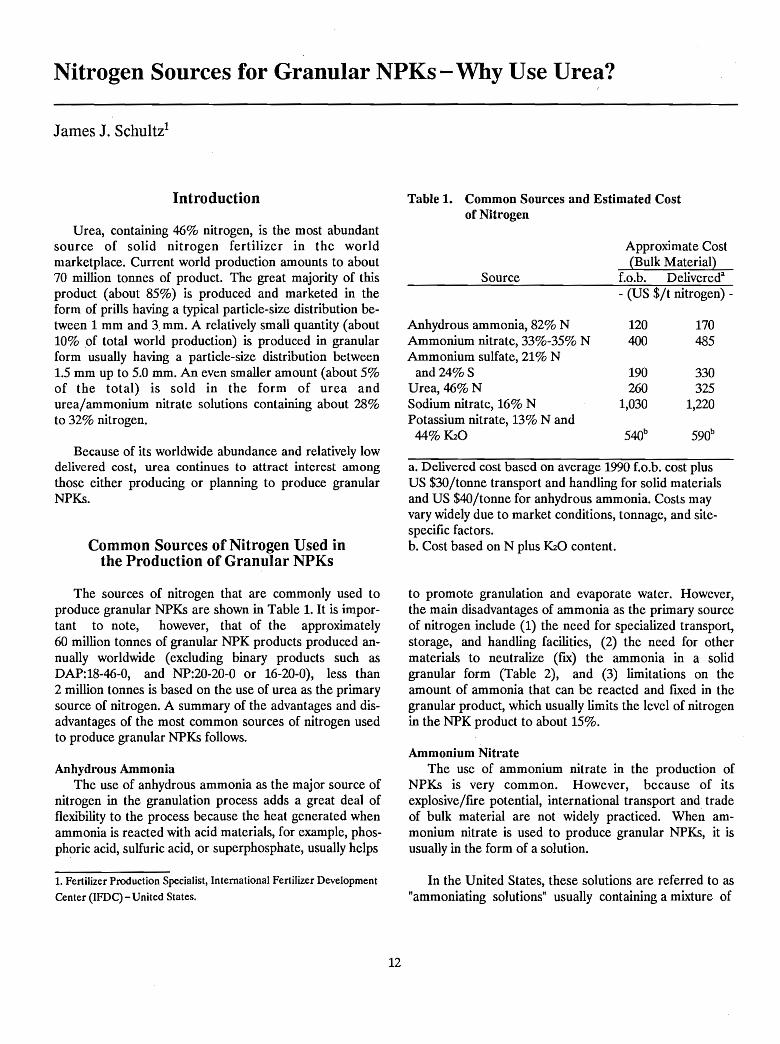
Table 1. Common Sources and Estimated Costof Nitrogen
Anhydrous ammonia, 82% N 120 170Ammonium nitrate, 33%-35% N 400 485Ammonium sulfate, 21% N
and 24%S 190 330Urea, 46% N 260 325Sodium nitrate, 16% N 1,030 1,220Potassium nitrate, 13% N and
44% K20 540b 590b
Introduction
Urea, containing 46% nitrogen, is the most abundantsource of solid nitrogen fertilizer in the worldmarketplace. Current world production amounts to about70 million tonnes of product. The great majority of thisproduct (about 85%) is produced and marketed in theform of prills having a typical particle-size distribution between 1 mm and 3. mm. A relatively small quantity (about10% of total world production) is produced in granularform usually having a particle-size distribution between1.5 mm up to 5.0 mm. An even smaller amount (about 5%of the total) is sold in the form of urea andurea/ammonium nitrate solutions containing about 28%to 32% nitrogen.
Source
Approximate Cost(Bulk Material)
f.o.b. Delivereda
- (US $/t nitrogen) -
Because of its worldwide abundance and relatively lowdelivered cost, urea continues to attract interest amongthose either producing or planning to produce granularNPKs.
Common Sources of Nitrogen Used inthe Production of Granular NPKs
The sources of nitrogen that are commonly used toproduce granular NPKs are shown in Table 1. It is important to note, however, that of the approximately60 million tonnes of granular NPK products produced annually worldwide (excluding binary products such asDAP:18-46-0, and NP:20-20-0 or 16-20-0), less than2 million tonnes is based on the use of urea as the primarysource of nitrogen. A summary of the advantages and disadvantages of the most common sources of nitrogen usedto produce granular NPKs follows.
Anhydrous AmmoniaThe use of anhydrous ammonia as the major source of
nitrogen in the granulation process adds a great deal offlexibility to the process because the heat generated whenammonia is reacted with acid materials, for example, phosphoric acid, sulfuric acid, or superphosphate, usually helps
1. Fertilizer Production Specialist, International Fertilizer Development
Center (IFDC) - United States.
12
a. Delivered cost based on average 1990 f.o.b. cost plusUS $30/tonne transport and handling for solid materialsand US $40/tonne for anhydrous ammonia. Costs mayvary widely due to market conditions, tonnage, and sitespecific factors.b. Cost based on N plus K20 content.
to promote granulation and evaporate water. However,the main disadvantages of ammonia as the primary sourceof nitrogen include (1) the need for specialized transport,storage, and handling facilities, (2) the need for othermaterials to neutralize (fIx) the ammonia in a solidgranular form (Table 2), and (3) limitations on theamount of ammonia that can be reacted and fIxed in thegranular product, which usually limits the level of nitrogenin the NPK product to about 15%.
Ammonium NitrateThe use of ammonium nitrate in the production of
NPKs is very common. However, because of itsexplosive/rITe potential, international transport and tradeof bulk material are not widely practiced. When ammonium nitrate is used to produce granular NPKs, it isusually in the form of a solution.
In the United States, these solutions are referred to as"ammoniating solutions" usually containing a mixture of
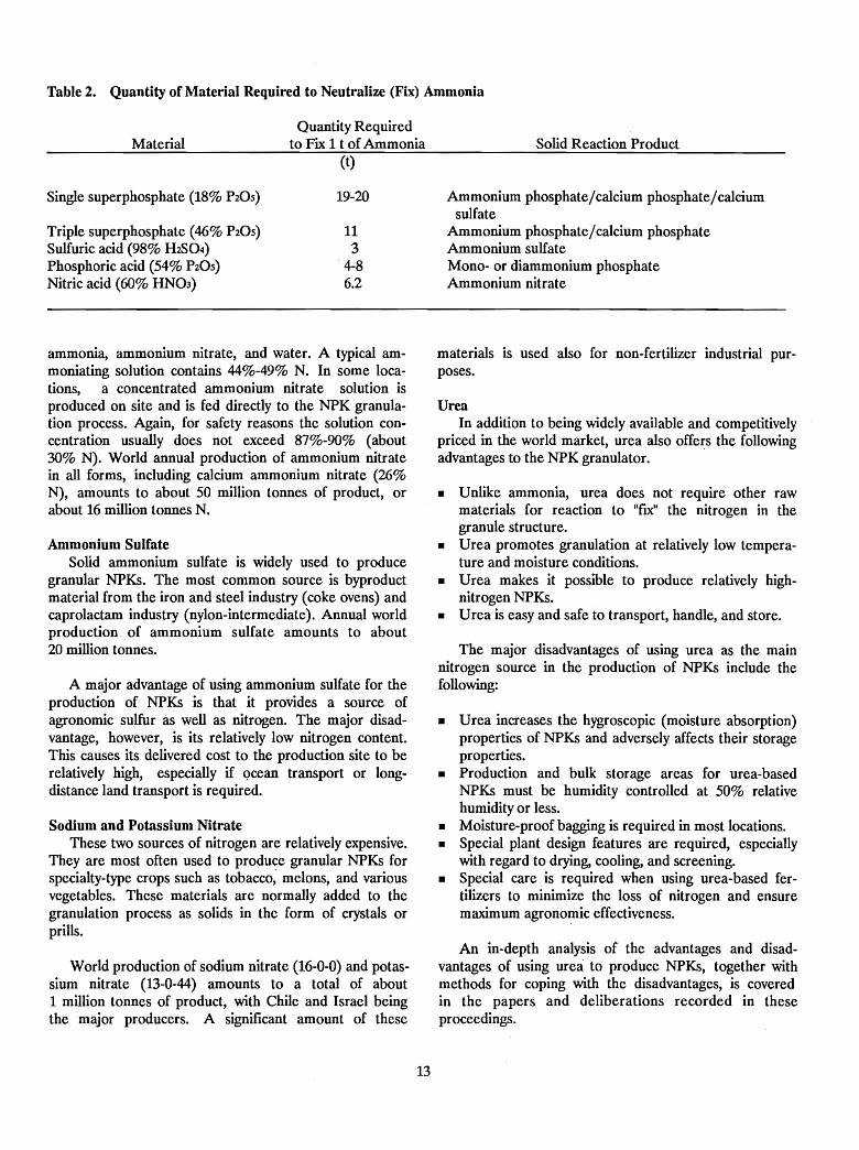
Table 2. Quantity of Material Required to Neutralize (Fix) Ammonia
Material
Single superphosphate (18% P20S)
Triple superphosphate (46% P20S)Sulfuric acid (98% H2S04)Phosphoric acid (54% P20S)Nitric acid (60% HN03)
Quantity Requiredto Fix 1 t of Ammonia Solid Reaction Product
(t)
19-20 Ammonium phosphate/calcium phosphate/calciumsulfate
11 Ammonium phosphate/calcium phosphate3 Ammonium sulfate
4-8 Mono- or diammonium phosphate6.2 Ammonium nitrate
ammonia, ammonium nitrate, and water. A typical ammoniating solution contains 44%-49% N. In some locations, a concentrated ammonium nitrate solution isproduced on site and is fed directly to the NPK granulation process. Again, for safety reasons the solution concentration usually does not exceed 87%-90% (about30% N). World annual production of ammonium nitratein all forms, including calcium ammonium nitrate (26%N), amounts to about 50 million tonnes of product, orabout 16 million tonnes N.
Ammonium SulfateSolid ammonium sulfate is widely used to produce
granular NPKs. The most common source is byproductmaterial from the iron and steel industry (coke ovens) andcaprolactam industry (nylon-intermediate). Annual worldproduction of ammonium sulfate amounts to about20 million tonnes.
A major advantage of using ammonium sulfate for theproduction of NPKs is that it provides a source ofagronomic sulfur as well as nitrogen. The major disadvantage, however, is its relatively low nitrogen content.This causes its delivered cost to the production site to berelatively high, especially if Qcean transport or longdistance land transport is required.
Sodium and Potassium NitrateThese two sources of nitrogen are relatively expensive.
They are most often used to produce granular NPKs forspecialty-type crops such as tobacco~ melons, and variousvegetables. These materials are normally added to thegranulation process as solids in the form of crystals orprills.
WorId production of sodium nitrate (16-0-0) and potassium nitrate (13-0-44) amounts to a total of about1 million tonnes of product, with Chile and Israel beingthe major producers. A significant amount of these
13
materials is used also for non-fertilizer industrial purposes.
UreaIn addition to being widely available and competitively
priced in the world market, urea also offers the followingadvantages to the NPK granulator.
• Unlike ammonia, urea does not require other rawmaterials for reaction to "fix" the nitrogen in thegranule structure.
• Urea promotes granulation at relatively low temperature and moisture conditions.
• Urea makes it possible to produce relatively highnitrogen NPKs.
• Urea is easy and safe to transport, handle, and store.
The major disadvantages of using urea as the mainnitrogen source in the production of NPKs include thefollowing:
• Urea increases the hygroscopic (moisture absorption)properties of NPKs and adversely affects their storageproperties.
• Production and bulk storage areas for urea-basedNPKs must be 'humidity controlled at 50% relativehumidity or less.
• Moisture-proof bagging is required in most locations.• Special plant design features are required, especially
with regard to drying, cooling, and screening.• Special care, is required when using urea-based fer
tilizers to, minimize the loss of nitrogen and ensuremaximurn agronomic effectiveness.
An in-depth analysis of the advantages and disadvantages of using urea to produce NPKs, together withmethods for coping with the disadvantages, is coveredin the papers and deliberations recorded in theseproceedings.
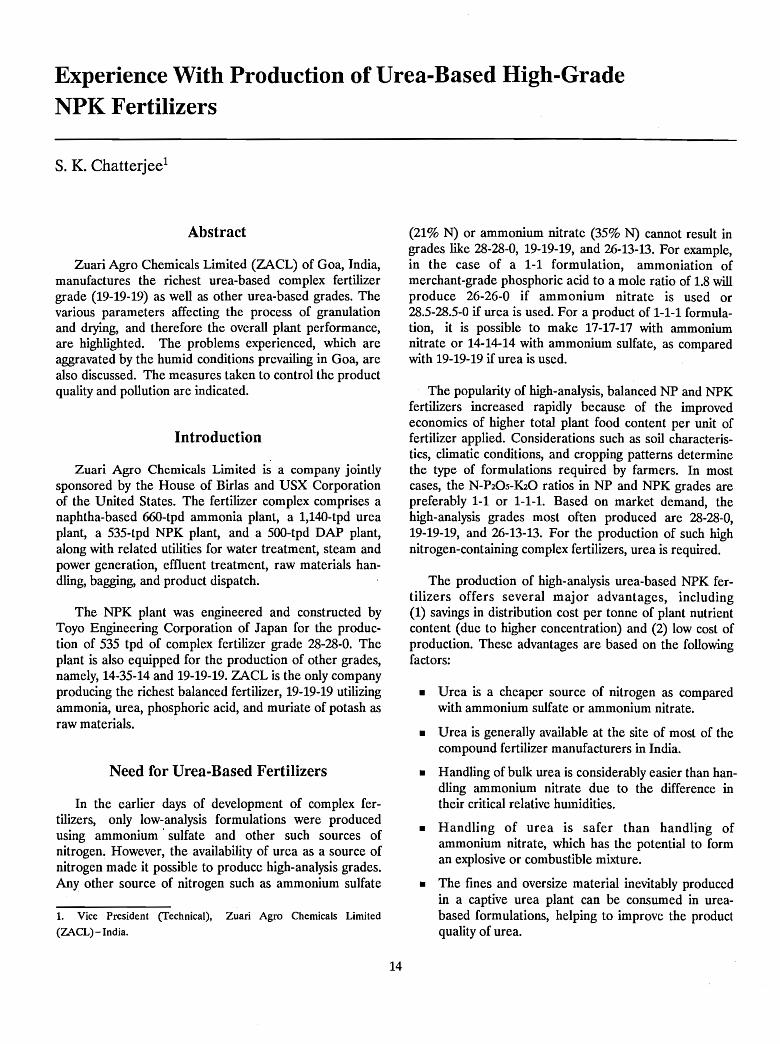
Experience With Production of Urea-Based High-GradeNPK Fertilizers
s. K. Chatterjee l
Abstract
Zuari Agro Chemicals Limited (ZACL) of Goa, India,manufactures the richest urea-based complex fertilizergrade (19-19-19) as well as other urea-based grades. Thevarious parameters affecting the process of granulationand drying, and therefore the overall plant performance,are highlighted. The problems experienced, which areaggravated by the humid conditions prevailing in Goa, arealso discussed. The measures taken to control the productquality and pollution are indicated.
Introduction
Zuari Agro Chemicals Limited is a company jointlysponsored by the House of Birlas and USX Corporationof the United States. The fertilizer complex comprises anaphtha-based 66O-tpd ammonia plant, a 1,140-tpd ureaplant, a 535-tpd NPK plant, and a 500-tpd DAP plant,along with related utilities for water treatment, steam andpower generation, effluent treatment, raw materials handling, bagging, and product dispatch.
The NPK plant was engineered and constructed byToyo Engineering Corporation of Japan for the production of 535 tpd of complex fertilizer grade 28-28-0. Theplant is also equipped for the production of other grades,namely, 14-35-14 and 19-19-19. ZACL is the only companyproducing the richest balanced fertilizer, 19-19-19 utilizingammonia, urea, phosphoric acid, and muriate of potash asraw materials.
Need for Urea-Based Fertilizers
In the earlier days of development of complex fertilizers, only low-analysis formulations were producedusing ammonium' sulfate and other such sources ofnitrogen. However, the availability of urea as a source ofnitrogen made it possible to produce high-analysis grades.Any other source of nitrogen such as ammonium sulfate
1. Vice President (fechnical), Zuari Agro Chemicals Limited
(ZACL) - India.
14
(21% N) or ammonium nitrate (35% N) cannot result ingrades like 28-28-0, 19-19-19, and 26-13-13. For example,in the case of a 1-1 formulation, ammoniation ofmerchant-grade phosphoric acid to a mole ratio of 1.8 willproduce 26-26-0 if ammonium nitrate is used or28.5-28.5-0 if urea is used. For a product of 1-1-1 formulation, it is possible to make 17-17-17 with ammoniumnitrate or 14-14-14 with ammonium sulfate, as comparedwith 19-19-19 if urea is used.
The popularity of high-analysis, balanced NP and NPKfertilizers increased rapidly because of the improvedeconomics of higher total plant food content per unit offertilizer applied. Considerations such as soil characteristics, climatic conditions, and cropping patterns determinethe type of formulations required by farmers. In mostcases, the N-P20S-K20 ratios in NP and NPK grades arepreferably 1-1 or 1-1-1. Based on market demand, thehigh-analysis grades most often produced are 28-28-0,19-19-19, and 26-13-13. For the production of such highnitrogen-containing complex fertilizers, urea is required.
The production of high-analysis urea-based NPK fertilizers offers several major advantages, including(1) savings in distribution cost per tonne of plant nutrientcontent (due to higher concentration) and (2) low cost ofproduction. These advantages are based on the followingfactors:
• Urea is a cheaper source of nitrogen as comparedwith ammonium sulfate or ammonium nitrate.
• Urea is generally available at the site of most of thecompound fertilizer manufacturers in India.
• Handling of bulk urea is considerably easier than handling ammonium nitrate due to the difference intheir critical relative humidities.
• Handling of urea is safer than handling ofammonium nitrate, which has the potential to forman explosive or combustible mixture.
• The fines and oversize material inevitably producedin a captive urea plant can be consumed in ureabased formulations, helping to improve the productquality of urea.
• In countries like India where no natural source of sulfur is available, the use of urea instead of ammoniumsulfate results in a saving of precious foreignexchange.
Technology of Urea-BasedNPK Fertilizers
Urea is used in the formulation of granulated compound fertilizers in one of the following ways:
Urea/superphosphate-based products using ordinarysuperphosphate or triple superphosphate along withmuriate of potash.
Urea/ammonium phosphate-based products usingeither solid mono- or diammonium phosphate (MAPor DAP) or ammoniation of wet-process phosphoricacid.
At ZACL, we manufacture urea/ammoniumphosphate-based complex fertilizers using the conventional phosphoric acid neutralization process. The plantwas commissioned in 1975. A description of the process,along with an account of our experience with the production of such high-grade compound fertilizers, follows.
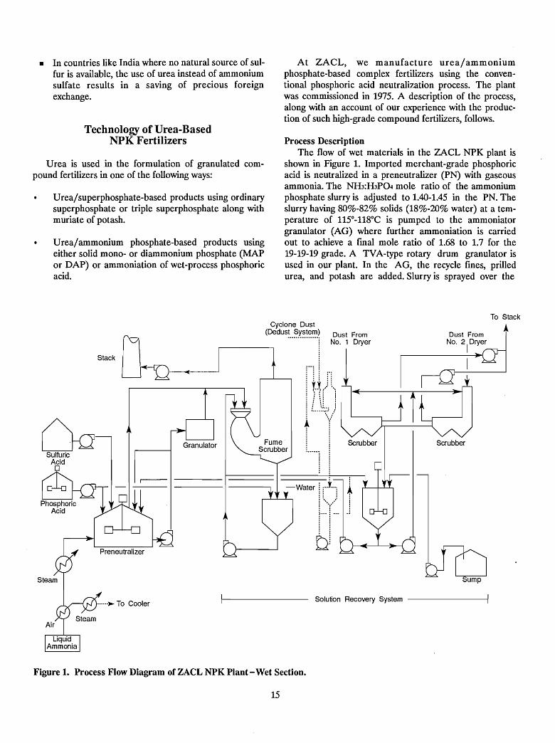
Process DescriptionThe flow of wet materials in the ZACL NPK plant is
shown in Figure 1. Imported merchant-grade phosphoricacid is neutralized in a preneutralizer (PN) with gaseousammonia. The NH3:H3P04 mole ratio of the ammoniumphosphate slurry is adjusted to 1.40-1.45 in the PN. Theslurry having 80%-82% solids (18%-20% water) at a temperature of 11SO-118°C is pumped to the ammoniatorgranulator (AG) where further ammoniation is carriedout to achieve a final mole ratio of 1.68 to 1.7 for the19-19-19 grade. A TVA-type rotary drum granulator isused in our plant. In the AG, the recycle fines, prilledurea, and potash are added. Slurry is sprayed over the
To Stack
Dust FromNo. 2
1
Dryer
Solution Recovery System
Water ! ;.J..::: :
!:""()
£1'"
Cyclone Dust(Dedus~..~y'~!~~) Dust From
NO.1 Dryer
I'Hr,lJ1 \(
1"·"11
Preneutralizer
Granulator
.....~ To Cooler
smCk~~
Ck1Sulfuric
Acid
Figure 1. Process Flow Diagram of ZACL NPK Plant - Wet Section.
15
rolling mass, and ammoniation is carried out by injectionof liquid ammonia through a sparger located beneath thebed of material in the AG. The heat of reaction in the AGevaporates part of the free water from the slurry and alsoincreases the temperature of the material. The extent ofammoniation in the AG depends upon the requirement ofammoniacal nitrogen in the fmal product. Since ammoniais the cheapest form of nitrogen, it is desirable to maximize its use in the AG for high-analysis products. Anotheradvantage of using a maximum amount of ammonia in theAG is a reduced dryer load because more waterevaporates in the AG as a result of additional heat of reaction. However, this advantage is offset to some extent bythe higher loss of ammonia from the fume scrubber whenthe higher level of ammoniation is performed in the AG;thus, ammoniation and ammonia losses must beoptimized.
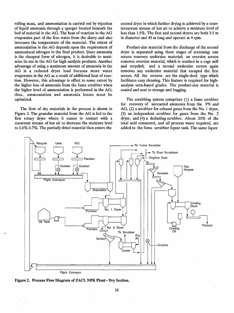
The flow of dry materials in the process is shown inFigure 2. The granular material from the AG is fed to thefIrst rotary dryer where it comes in contact with acocurrent stream of hot air to decrease the moisture levelto 1.6%-1.7%. The partially dried material then enters the
second dryer in which further drying is achieved by a countercurrent stream of hot air to achieve a moisture level ofless than 1.5%. The first and second dryers are both 3.5 min diameter and 43 m long and operate at 4 rpm.
Product-size material from the discharge of the seconddryer is separated using three. stages of screening: onescreen removes undersize material; an oversize screenremoves oversize material, which is crushed in a cage milland recycled; and a second undersize screen againremoves any undersize material that escaped the fIrstscreen. All the screens are the single-deck type whichfacilitates easy cleaning. This feature is required for highanalysis urea-based grades. The product-size material iscoated and sent to storage and bagging.
The scrubbing system comprises (1) a fume scrubberfor recovery of unreacted ammonia from the PN andAG, (2) a scrubber for exhaust gases from the No.1 dryer,(3) an ,independent scrubber for gases from the No. 2dryer, and (4) a dedusting scrubber. About 20% of thetotal acid consumed, and all process water required, areadded to the fume scrubber liquor tank. The same liquor
...-------~ To Fume Scrubber
~ To Dust Scrubbers
Fugitive Dust
CoatingDrum
bL~Product
CoatingOil
Flight Conveyor
Figure 2. Process Flow Diagram of ZACL NPK Plant - Dry Section.
16
is then pumped to both dryer scrubbers via the dedustingscrubber. The fmal liquor from the dust scrubber tank ispumped to the PN.
Operating ExperienceNeutralization Section - The major problem ex
perienced in the operation of the PN has been foamingcaused by excessive dust generation and high urea concentration in the scrubber liquor (about 5%). Thisproblem is more prominent during the production of28-28-0 grade, which requires a larger quantity of urea.The main reason for the dust formation is the breaking ofthe granules in the dryer. It has been our experience thatexcessive foaming reduces the slurry pumping rate andconsequently decreases the production rate. We try toreduce the level of foaming by using antifoamer, as well asby optimizing the dryer conditions to decrease the amountof dust generated.
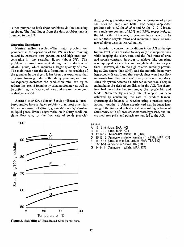
Ammoniator-Granulator Section - Because ureabased grades have a higher solubility than most other fertilizers, as shown in Figure 3, granulation is very sensitiveto liquid phase. Even a slight variation in slurry condition,slurry flow rate, or the flow rate of solids (recycle)
disturbs the granulation resulting in the formation of excessive fines or lumps and balls. The design recycle-toproduct ratio is 6.7 for 28-28-0 and 5.6 for 19-19-19 basedon a moisture content of 2.5% and 2.3%, respectively, atthe AG outlet. However, experience has enabled us toreduce these recycle ratios and maintain a moisture content of about 2.6% at the AG outlet.
In order to control the conditions in the AG at the optimurn level, it is desirable to vary only the recycled fineswhile keeping the slurry rate and the feed rates of ureaand potash constant. In order to achieve this, our plantwas equipped with a bin and weigh feeder for recyclefines. However, due to the high relative humidity prevailing at Goa (more than 80%), and the material being veryhygroscopic, it was found that recycle fmes would not flowuniformly from the bin despite the provision of vibrators.Thus this system became a hindrance rather than a help inmaintaining the desired conditions in the AG. We therefore had no choice but to remove the recycle bin andfeeder. Subsequently, a steady rate of recycle has beenachieved by controlling the rate of product takeout(returning the balance to recycle) using a product surgehopper. Another problem experienced was frequent jamming of the urea and potash crushers resulting in frequentshutdowns. Both of these crushers were bypassed, and uncrushed urea prills and potash are now fed to the AG.
LegendA 19-19-19 (Urea, DAP, KGI)B 18-18-18 (Urea, MAP, KGI)G 17-17-17 (Ammonium nitrate, DAP, KGI)o 15-15-15 (Ammonium nitrate, ammonium SUlfate, MAP, KGI)E 15-15-15 (Urea, ammonium sulfate, MAP, TSP, KGI)F 14-14-14 (Ammonium sulfate, DAP, KGI)G 14-14-14 (Ammonium sulfate, MAP, KGI)
100
80 1--~-=::.-+__---+__--______1
50 '--- -'-- -'----__------J
70
90 ~-=-......~=---=~-+-------jco
:.;::::;::Joen0)
ooT"""-....0)
80 90Ternperature, °c
Figure 3. Solubility of Urea-Based NPK Fertilizers.
.~ 70 1----1------+------1
:.a::Joen
100 .--------_,...--------r-------,
17
A proper size of material at the discharge of thegranulator is a very important operating parameter forurea-based NPKs. We have faced considerable difficultiesin granulation. The product exiting the granulator is justagglomerated and normally not formed into good (strong)granules. Our AG is 3.5 m in diameter and 9 m long, andit operates at 9.0 rpm. The retainer ring is located 6 mfrom the inlet. The slurry spray is completed in the frrst3 m, and ammoniation takes place up to 5.5 m from the inlet. After the retainer ring, the material simply rolls andgranulation takes place. If too much undergranulation occurs, we inject steam into the bed of material usingmanual control.
The locations of the slurry nozzle and ammoniasparger playa very important role in granulation. Theoriginal slurry nozzles were fitted in the 4:30 otclock position when viewed from the discharge of the AG; instead ofusing an ammonia sparger, we used pipe-type injectorsembedded in the rolling mass. This arrangement resultedin very poor granule formation, and the loss of ammoniawas high. The slurry nozzles were then replaced by slots inthe header, and the slurry was dribbled on the bed in the6 o'clock position. This arrangement was further modifiedby the use of spray nozzles, and a horizontal slotted pipetype ammonia sparger was installed. These modificationsresulted in considerable improvement in granulation.However, further improvement is needed, and we proposenow to locate the slurry nozzles in a manner so that thespray is horizontal and falls more fully on the rolling massof material in the granulator. We also plan to relocate theammonia sparger to the 4:30 otclock position. This willhelp to ensure that improved ammoniation will take placeand that proper size granules are formed.
Our granulator does not have rubber paneling andthere is a lot of buildup in the granulator; this must beremoved by the scraper. Granule formation is also poordue to the limited rolling action in the absence of rubberpanels. Our plant is based on the technology of the 1970s,and since then a lot of changes have taken place. Wepropose to replace the granulator totally with a rubberpaneled unit in due course.
In addition to the above, to obtain proper granulationthere should be an optimum amount of liquid phase andheat release in the granulator. We have checked the liquidphase and the heat of reaction in the granulator. Theliquid phase is 300 kg/tonne of product, which is satisfactory; however, the heat release is only 20,000 kcal/tonne,which is grossly inadequate. To increase this heat release,we propose to increase the ammoniation in the granulatorby operating the PN at a 0.5-0.6 mole ratio and bringingthe mole ratio up to 1.6 in the granulator. With this increased level of ammoniation, escape of ammonia from
18
the granulator is likely to increase, in which case wepropose to scrub the off gases in the fume scrubber by adding additional phosphoric acid and taking the overflowinto the PN. Presently, we maintain the pH at 5-6 in thefume scrubber, and we would like to bring this down to apH of 2; however, this may increase the emission offluorine from the stack.
Drying Section - It is interesting to note that granulation also takes place in the dryer where the material temperature is high. We have removed the first row of flightsin the first dryer to facilitate granule formation. In thedryer, the rate of drying depends upon the material temperature and its moisture content as well as the temperature of hot air and its humidity. Urea-based fertilizershaving a low melting point pose a limitation on theallowable drying temperature to avoid fusing of material.The hot air temperature used by ZACL is 130°-140°C atthe No.1 dryer inlet and 90°-100°C at the No.2 dryer inletfor all grades. The temperature of the material at the outlet of the No.1 dryer is 64°C and remains about the sameat the outlet of the second dryer.
The drying operation is very critical in the sense thatexcessive dust is produced if the material is overdried andthe material remains sticky if it is underdried. In order tomaintain proper conditions in the drying operation,dehumidified air is used as dilution air in the dryer furnaces to control the relative humidity of the inlet air. Wehave noticed that product breakage occurs in the firstdryer and further granulation occurs in the second dryer.Because of fusion of material in the second dryer due tolow moisture and excessive temperature, deposits ofmaterial occur, and the dryer becomes overloaded.
We have used the second dryer as a cooler to avoid theproblem of fusion and deposition (buildup). When we didthis, the drying was still very effective but the granulationwas very poor because of the low temperature of therecycle material and low moisture content. However, thiscooling improved the hardness of the material, and therewas better screening; the performance of the cage millalso improved considerably.
We propose to use the No. 2 dryer as a cooler againafter changing to the new operating parameters (0.6 moleratio in the preneutralizer and more ammoniation in thegranulator).
Screening, Recycle, and Product CoatingSection - The problem faced in the screening section is thefailure of vibrators and tearing of the screen meshes. Theoriginal electromagnetic-type vibrators were replaced witheccentric-type motor-driven vibrators. All screens are ofthe slotted opening type. We initially had a first screen
with a 2.25-mm by 50-mm opening, oversize screen with a4-mm by 2O-mm opening, and undersize screen with a2.5-mm by 10-mm opening. Because the Fertilizer ControlOrder (FCO) specifies product size of 1-4 mm, wechanged the slotted opening-type screen size to 2 mm by20 mm, 4.5 mm by 35 mm, and 2 mm by 20 mm, respectively. This has helped in drawing more product sizematerial from the system, thereby increasing productionappreciably.
The critical relative humidity of urea-based NPKgrades produced by ZACL is 45%-50% at 30°C, and therelative humidity prevailing at Goa for most of the year isabout 80%. Therefore, the product is coated with asuitable coating agent to retain its storage characteristics,particularly in off-seasons, when the bagged material liesin warehouses for 3 months. Initially, the product wascoated with talc and oil. The problem of separation of talcwas noticed, and the coating was no.t effective. At presentthe product is coated with a liquid coating agent only, andthis has given good results.
Scrubbing Section - We indicated earlier that themajor problem faced with foaming in the PN is caused byhydrolysis of urea contained in the scrubber solution. Wehave made a provision for steam injection in the dustscrubber liquor tank to facilitate partial removal of C02. Ithas been observed that foaming in the PN is somewhatreduced as a result.
Blockage of the dryer cyclones and buildup of solids inducts result in considerable overloading of the scrubbersand affect the air flow through the dryers. Manometerswere installed at various lo<;ations, and the cyclones, ducts,and fans are cleaned thoroughly once every 2 weeks ofplant operation to overcome this problem. Presently, themole ratio in the scrubber liquor is maintained at 1.2-1.3.We propose to feed a larger portion of acid to the fumescrubber liquor tank; this is expected to reduce the moleratio as well as the ammonia loss and help to decrease theproblem of choking of the venturi system.
Quality ControlIt is essential that the different grades conform in
quality to the specifications laid down in the FCO instituted by the Government of India. The FCO permitsonly the variation of 0.6 of a unit for an individual nutrientand a total of 1.5 units for the 19-19-19 NPK grade. Thefeed rates of urea and potash are controlled accuratelyusing belt-type weigh feeders. The flow rates of phosphoric acid, ammonia, and slurry are also controlled usingmagnetic flowmeters. The accurate control of the rawmaterial feed rates has helped to maintain good productquality. Depending upon the product analysis, the feedrates of urea and potash are adjusted accordingly. The
19
samples are collected on 1Y2-hour intervals from the finalproduct conveyor belt. To minimize the variation, theproduction of each 8-hour shift is stored in a separate bin.Once in 30 minutes, samples are collected from the different portions of the pile and a composite is made andanalyzed. The average analysis has to conform to FCOspecifications; otherwise the material is declared "off-spec"and recycled back to the system. Only the material conforming to the FeD -specifications- is-bagged and dispatched.
Because our product is very hygroscopic and moistureabsorption generally results in reduced mechanicalstrength and increased caking, the product is coated with aspecial coating agent. Deterioration of the product qualityduring storage and bagging is minimized, as the NPK bulkstorage building is dehumidified.
Pollution ControlAs described earlier, unreacted ammonia from the PN
and the AG and exhaust gases from the first and seconddryer cyclones and the dedusting cyclones are scrubbedwith recovered solution. A portion of phosphoric acidused in the process is added to the recovered solution tankfor improved scrubbing (recovery) of ammonia. Theoptimum pH of the scrubbing liquor is maintained at 5-6to minimize the problem of buildup in the dust scrubbersand to reduce foaming and simultaneously achieve thedesired ammonia scrubbing efficiency.
To overcome the problem of occasional dust exhaustfrom the chimney, a constant watch is kept on the performance of the cyclones. For this purpose, manometer readings at different locations along the route of thedust-handling ducts, from the point of dust pickup
to the exhaust stack, are constantly monitored, and timelycleaning is carried out as indicated by the monometerreadings. Under normal operating conditions, the exhaustfrom the stack is not visible.
No liquid. effluent is discharged from the plant. Pumpgland leakage, overflows, and drainage from scrubbersand other process vessels are collected in a waterproofand acid-proof brick-lined tank having three compartments. The liquor collected in the last compartment ispumped to the recovery section at a steady rate. In orderto avoid settling of sludge, the solution in the tank is constantly agitated using steam spargers. All solid spillage inthe plant is recovered on a day-to-day basis and recycledto the system. Because the 19-19-19 grade is veryhygroscopic, any spillage becomes wet quickly, causingadditional problems in its recovery.
Conclusion
Economics favor the use of urea for manufacturinghigh-analysis NPK grades. The major problems, namely,foaming in the preneutralizer and buildup of material inthe equipment, were overcome by optimizing theoperating conditions and through certain equipmentmodifications. We are continuing to implement changes inthe operation as mentioned earlier, and these changes arelikely to improve the plant performance further and improve production capacity. Once we improve the granulation and decrease the recycle ratio to 3.0, we propose toconsider use of a pipe reactor to further optimize theproduction unit.
20
Operational Experiences With NP-NPK Granulation atCoromandel Fertilisers Lilllited - India
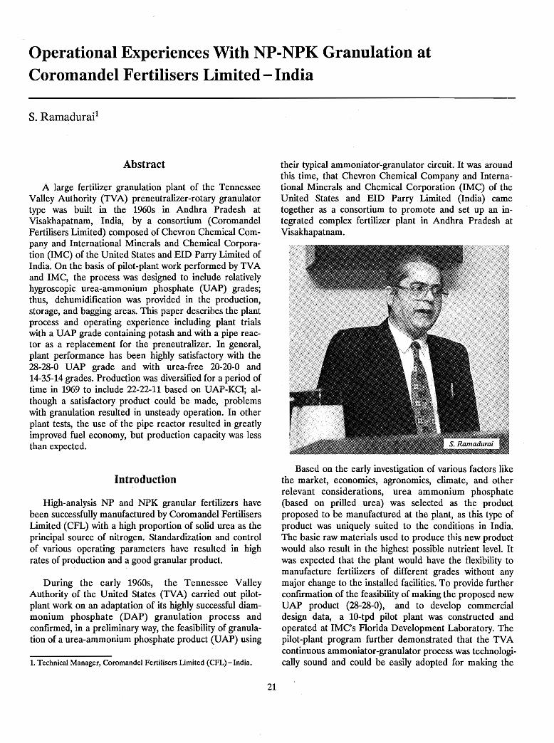
s. Ramadurai1
Abstract
A large fertilizer granulation plant of the TennesseeValley Authority (TVA) preneutralizer-rotary granulatortype was built in the 1960s in Andhra Pradesh atVisakhapatnam, India, by a consortium (CoromandelFertilisers Limited) composed of Chevron Chemical Company and International Minerals and Chemical Corporation (1MC) of the United States and EID Parry Limited ofIndia. On the basis of pilot-plant work performed by TVAand IMC, the process was designed to include relativelyhygroscopic urea-ammonium phosphate (UAP) grades;thus, dehumidification was provided in the production,storage, and bagging areas. This paper describes the plantprocess and operating experience including plant trialswith a UAP grade containing potash and with a pipe reactor as a replacement for the preneutralizer. In general,plant performance has been highly satisfactory with the28-28-0 UAP grade and with urea-free 20-20-0 and14-35-14 grades. Production was diversified for a period oftime in 1969 to include 22-22-11 based on UAP-KCI; although a satisfactory product could be made, problemswith granulation resulted in unsteady operation. In otherplant tests, the use of the pipe reactor resulted in greatlyimproved fuel economy, but production capacity was lessthan expected.
Introduction
High-analysis NP and NPK granular fertilizers havebeen successfully manufactured by Coromandel FertilisersLimited (CFL) with a high proportion of solid urea as theprincipal source of nitrogen. Standardization and controlof various operating parameters have resulted in highrates of production and a good granular product.
During the early 1960s, the Tennessee ValleyAuthority of the United States (TVA) carried out pilotplant work on an adaptation of its highly successful diammonium phosphate (DAP) granulation process andconfirmed, in a preliminary way, the feasibility of granulation of a urea-ammonium phosphate product (UAP) using
1. Technical Manager, Coromandel Fertilisers Limited (CFL) - India.
21
their typical ammoniator~granulator circuit. It was aroundthis time, that Chevron Chemical Company and International Minerals and Chemical Corporation (IMC) of theUnited States and EID Parry Limited (India) cametogether as a consortium to promote and set up an integrated complex fertilizer plant in Andhra Pradesh atVisakhapatnam.
Based on the early investigation of various factors likethe market, economics, agronomics, climate, and otherrelevant considerations, urea ammonium phosphate(based on prilled urea) was selected as the productproposed to be manufactured at the plant, as this type ofproduct was uniquely suited to the conditions in India.The basic raw materials used to produce this new productwould also result in the highest possible nutrient levet Itwas expected that the plant would have the flexibility tomanufacture fertilizers of different grades without anymajor change to the installed facilities. To provide furtherconfIrmation of the feasibility of making the proposed newUAP product (28-28-0), and to develop commercialdesign data, a 10-tpd pilot plant was constructed andoperated at IMC's Florida Development Laboratory. Thepilot-plant program further demonstrated that the TVAcontinuous ammoniator-granulator process was technologically sound and could be easily adopted for making the
new UAP grade with relatively few modifications to a typical DAP manufacturing facility.
Process Description
fed back to the reactor along with 48% P20S phosphoricacid. The CFL fertilizer plant makes UAP 28-28-0 and14-35-14 (a urea-free NPK formulation). The specifications of these two products are given in Table 1.
The main raw materials used in the granulationprocess are (a) wet-process phosphoric acid of 28%-30%and 46%-48% P20S concentration, (b) anhydrous ammonia, and (c) urea prills. Muriate of potash is used formaking NPK formulations.
The 46%-48% phosphoric acid and the weak phosphoric acid from the scrubber recovery system are partlyneutralized to a NH3:H3P04 mole ratio of 1.4 to 1.45 withanhydrous ammonia in the reactor (preneutralizer); further ammoniation of this mixture is performed in theammoniator-granulator. The mixture of monoammoniumand diammonium phosphate formed in the reactor has themaximum solubility at this mole ratio, and the resultantslurry can be handled with relative ease with slurry pumpsat a relatively low moisture level of 16%-18%. This is veryimportant because an excessive increase in water fed tothe granulator circuit adversely affects the granulation ofUAP formulations.
Table 1. Specifications of UAP Products8
28-28-0 14-35-14
Total nitrogen (N) 28.0 14.0Nitrate N Nil NilAmmoniacal N (min.) 9.0 14.0Total available phosphate,
as P20S (min.) 28.0 35.0Water-soluble phosphate,
as P20S (min.) 25.2 29.0Free moisture (max.) 1.5 1.0Water-soluble K20 14.0
a. Product is uniform in color, shape, and texture. Uncoated urea prills are not visible.
Important Aspects ofUAP Plant Operation
• Reactor and scrubber control.• Granulation control.• Drying and cooling control.
Reactor and Scrubber ControlIn view of the influence of the temperature and mois
ture control on the performance of the granulation anddrYing operations with UAP formulations, a good understanding of the complete water and heat balance of theprocess is important. The operating parameters of thereactor are:
The operating experience of CFL during the manufacture of UAF has provided an understanding of the effectsof various process variables, leading to better control ofthe operating variables and an improvement in the overallperformance of the plant. Of the various factors, the following have been found to be critical from the point ofview of continuous operation and production of an acceptable product at peak loads.
116°-120°C1.40-1.451.5-1.555-5.516%-18%
• Slurry temperature• NH3:H3P04 mole ratio• Slurry specific gravity• SlurrypH• Slurry free moisture
A scrubbing system is used to recover unreacted ammonia vapor vented from the reactor and granulator andfme dust particles from the dryer and cooler cyclones. Thescrubbing is achieved by intimately contacting the effluents with a weak circulating phosphoric acid solution ina venturi-type scrubber. A 30% P20S phosphoric acidsolution and process water are continuously fed to thescrubber system to maintain the acidity required for theabsorption of ammonia and to give sufficient dilution tokeep the ammonium phosphate and recovered dust in solution. A continuous stream of weak scrubber recycle acid is
The ammonium phosphate slurry from the reactor ispumped to the granulator and evenly distributed over abed of recycled material consisting of prilled urea, undersize granules from the' screens, crushed oversize from thecage mills, and fertilizer dust from dust collectingcyclones. Vapor ammonia is introduced at this stage to further ammoniate the ammonium phosphate slurry to a 1.6mole ratio. The granules discharged from the granulatorare dried to a moisture level of 1% in a cocurrent rotarydryer. Drying is followed by screening to separate the onsize material as the fmal product. The oversize materialfrom the screens is crushed and along with the undersizeand the dust from the cyclones is returned to thegranulator. Recycle control is provided by returning partof the onsize product to the granulator. The prilled urea isintroduced into the granulator along with recycledmaterial.
22
The operating parameters of the scrubber systemfollow:
The granulator originally provided was a modifiedTVA-type rotary ammoniator-granulator with a sawtoothtype slurry distribution system. A retaining dam located
The current liquid-to-gas ratio in the reactor/granulator scrubber is 290 L/100 m3 of gas. The possibility of handling higher airflows and liquid flows is beingstudied. Scaling in the venturi scrubbers occurs graduallyand is removed during scheduled shutdowns.
75°-79°C2.5%-3%35%-40%
1.66.5-7.0
13,600 m3Jh(8,000 cfrn)'
• Bed temperature• Moisture of material at outlet• Percentage of product size
material at outlet• NH3:H3P04 mole ratio (outlet)• pH of product.• Airflow through granulator
midway separated the ammoniation and granulatingzones. An ammonia sparger pipe was located in the bed ofmaterial in the ammoniation zone. A mechanical scraperwas located inside the granulator to continuously removeany material buildup from the shell. The granulation zone,on the other hand, has no internals and operates with arelatively shallow bed of material.
When the plant was first started on a short trial runproducing DAP, it was found that granulation control wasrelatively easy. However, the addition of urea soonresulted in an unsteady operation, and granulation becamevery difficult. It was observed that the distribution of theslurry was far from satisfactory, resulting in dry and wetzones in different areas along the length of the ammoniation zone. Heavy material buildup on the internals furtheraggravated the conditions inside the granulator by inhibiting the rolling and tumbling action that is essential forgood granulation. The sawtooth slurry distribution was replaced with spray nozzles, and the number of supports forthe ammonia sparger and the height of the retaining damwere both decreased. These. changes contributed to abetter rolling and tumbling action and helped in the formation of uniformly sized granules. The operatingparameters for the granulator follow:
1.27-1.291.1-1.250°-55°C20%-21%
• Scrubber liquor specific gravity• Scrubber liquor NH3:H3P04 mole ratio• Scrubber liquor temperature• Scrubber liquor P20S content
Granulation ControlEffective control of granulation is the key to successful
operation of the plant to achieve high production ratesand good-quality product. Ideally, it would be desirable tobe able to control granulation with a low recycle rate anda minimum moisture level at the granulator discharge toobtain granules of a uniform size distribution and chemical composition with good crushing strength. .
Most of the water enters the process by way of waterrecovered from the raw water injection on the impellers ofthe scrubber fans, which is needed to keep them clean.This helps in increasing the solubility of ammonium phosphate and fertilizer dust in the scrubber system. The weakand strong phosphoric acid feeds also contribute theirshare of water depending upon the actual concentration ofacid used. A major quantity of water is evaporated by theheat of neutralization in the reactor, leaving behind a concentrated ammonium phosphate solution. The moistslurry is the main source of moisture entering the granulation system; thus, necessary care should be taken in theoperation of the reactor and scrubber systems to ensurethat moisture input and evaporation balance each other toyield a low-moisture slurry. This should be consistent withsatisfactory fluidity of the resultant slur.ry. Ammoniumphosphates have maximum solubility at a mole ratio of1.40 to 1.45 and, therefore, the mole ratio of the slurry ismaintained at this level by proper adjustment of theammonia flow to the reactor. Excessive solid input to thereactor by way of unfiltered gypsum from wet-processphosphoric acid and undissolved salts in the weak acid generated due to improper control of the pH and moisture ofthe acid in the scrubber recovery system have a profoundeffect on the pumpability of the slurry. In order to containfoaming in the reactor and scrubber, antifoam is alsoadded to the scrubber sump. The antifoam is addedthrough a dosing pump, and the quantity of antifoam usedis closely monitored.
23
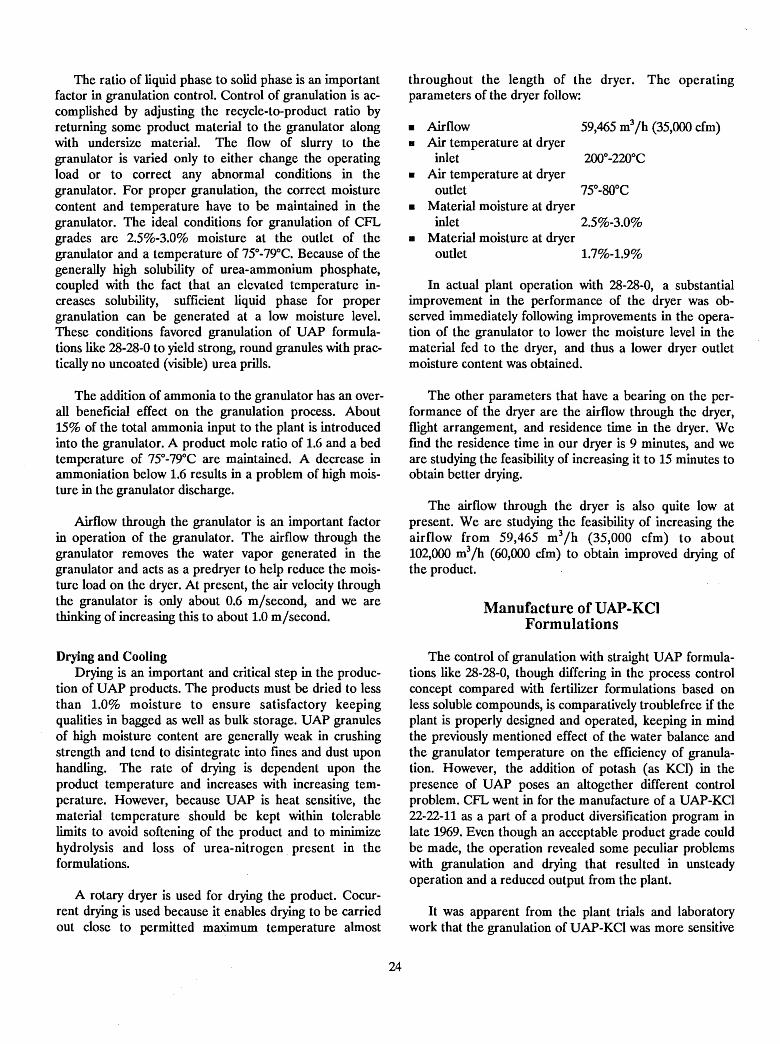
The ratio of liquid phase to solid phase is an importantfactor in granulation control. Control of granulation is accomplished by adjusting the recycle-to-product ratio byreturning some product material to the granulator alongwith undersize material. The flow of slurry to thegranulator is varied only to either change the operatingload or to correct any abnormal conditions in thegranulator. For proper granulation, the correct moisturecontent and temperature have to be maintained in thegranulator. The ideal conditions for granulation of CFLgrades are 2.5%-3.0% moisture at the outlet of thegranulator and a temperature of 75°-79°C. Because of thegenerally high solubility of urea-ammonium phosphate,coupled with the fact that an elevated temperature increases solubility, sufficient liquid phase for propergranulation can be generated at a low moisture level.These conditions favored granulation of UAP formulations like 28-28-0 to yield strong, round granules with practically no uncoated (visible) urea prills.
The addition of ammonia to the granulator has an overall beneficial effect on the granulation process. About15% of the total ammonia input to the plant is introducedinto the granulator. A product mole ratio of 1.6 and a bedtemperature of 75°-79°C are maintained. A decrease inammoniation below 1.6 results in a problem of high moisture in the granulator discharge.
Airflow through the granulator is an important factorin operation of the granulator. The airflow through thegranulator removes the water vapor generated in thegranulator and acts as a predryer to help reduce the moisture load on the dryer. At present, the air velocity throughthe granulator is only about 0.6 m/second, and we arethinking of increasing this to about 1.0 m/ second.
Drying and CoolingDrying is an important and critical step in the produc
tion of UAP products. The products must be dried to lessthan 1.0% moisture to ensure satisfactory keepingqualities in bagged as well as bulk storage. UAP granulesof high moisture content are generally weak in crushingstrength and tend to disintegrate into fines and dust uponhandling. The rate of drying is dependent upon theproduct temperature and increases with increasing temperature. However, because UAP is heat sensitive, thematerial temperature should be kept within tolerablelimits to avoid softening of the product and to minimizehydrolysis and loss of urea-nitrogen present in theformulations.
A rotary dryer is used for drying the product. Cocurrent drying is used because it enables drying to be carriedout close to permitted maximum temperature almost
24
throughout the length of the dryer. The operatingparameters of the dryer follow:
• Airflow 59,465 m3/h (35,000 cfm)• Air temperature at dryer
inlet 200°-220°C• Air temperature at dryer
outlet 75°-BOoC• Material moisture at dryer
inlet 2.5%-3.0%• Material moisture at dryer
outlet 1.7%-1.9%
In actual plant operation with 28-28-0, a substantialimprovement in the performance of the dryer was observed immediately following improvements in the operation of the granulator to lower the moisture level in thematerial fed to the dryer, and thus a lower dryer outletmoisture content was obtained.
The other parameters that have a bearing on the performance of the dryer are the airflow through the dryer,flight arrangement, and residence time in the dryer. Wefmd the residence time in our dryer is 9 minutes, and weare studying the feasibility of increasing it to 15 minutes toobtain better drying.
The airflow through the dryer is also quite low atpresent. Weare studying the feasibility of increasing theairflow from 59,465 m3/h (35,000 cfm) to about102,000 m3/h (60,000 cfm) to obtain improved drying ofthe product.
Manufacture ofUAP-KCIFormulations
The control of granulation with straight UAP formulations like 28-28-0, though differing in the process controlconcept compared with fertilizer formulations based onless soluble compounds, is comparatively troublefree if theplant is properly designed and operated, keeping in mindthe previously mentioned effect of the water balance andthe granulator temperature on the efficiency of granulation. However, the addition of potash (as KCI) in thepresence of UAP poses an altogether different controlproblem. CFL went in for the manufacture of a UAP-KCl22-22-11 as a part of a product diversification program inlate 1%9. Even though an acceptable product grade couldbe made, the operation revealed some peculiar problemswith granulation and drying that resulted in unsteadyoperation and a reduced output from the plant.
It was apparent from the plant trials and laboratorywork that the granulation of UAP-KCl was more sensitive
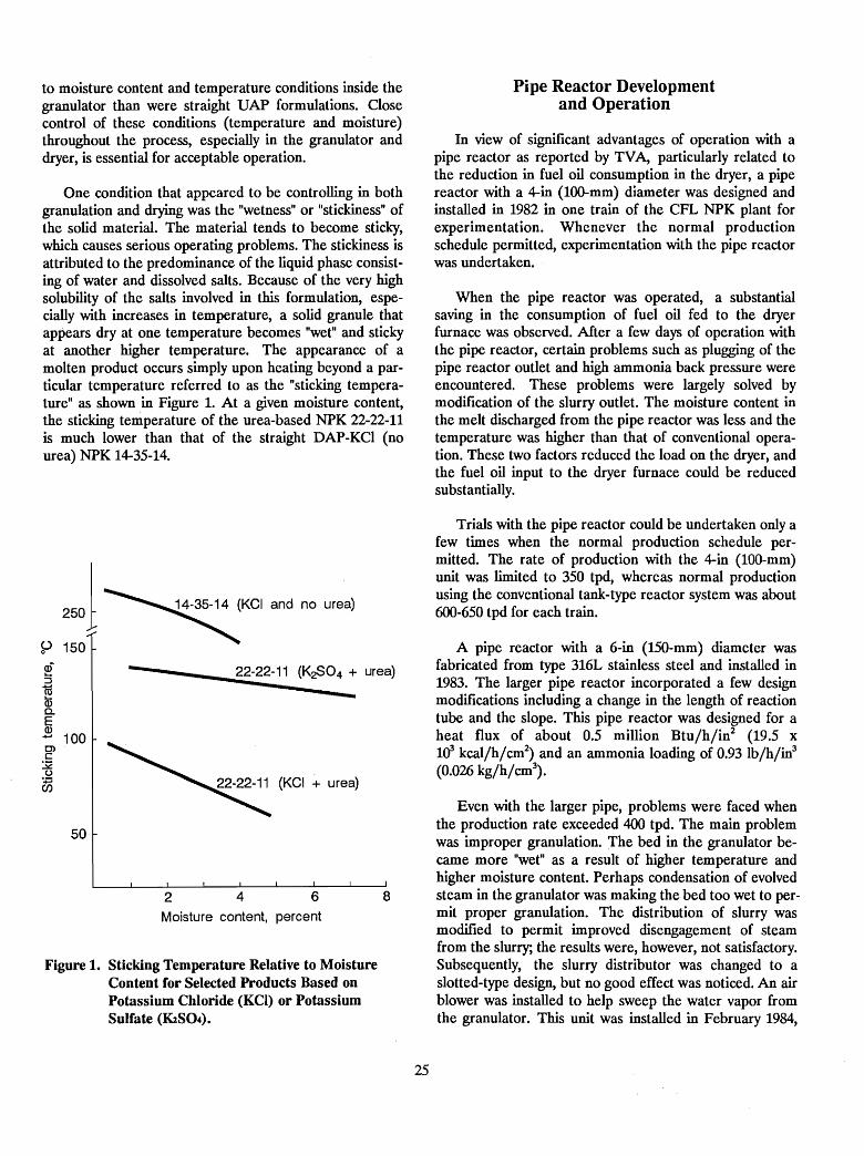
to moisture content and temperature conditions inside thegranulator than were straight UAP formulations. Closecontrol of these conditions (temperature and moisture)throughout the process, especially in the granulator anddryer, is essential for acceptable operation.
One condition that appeared to be controlling in bothgranulation and drying was the "wetness" or "stickiness" ofthe solid material. The material tends to become sticky,which causes serious operating problems. The stickiness isattributed to the predominance of the liquid phase consisting of water and dissolved salts. Because of the very highsolubility of the salts involved in this formulation, especially with increases in temperature, a solid granule thatappears dry at one temperature becomes "wet" and stickyat another higher temperature. The appearance of amolten product occurs simply upon heating beyond a particular temperature referred to as the "sticking temperature" as shown in Figure 1. At a given moisture content,the sticking temperature of the urea-based NPK 22-22-11is much lower than that of the straight DAP-KCI (nourea) NPK 14-35-14.
Pipe Reactor Developmentand Operation
In view of significant advantages of operation with apipe reactor as reported by TVA, particularly related tothe reduction in fuel oil consumption in the dryer, a pipereactor with a 4-in (l00-mm) diameter was designed andinstalled in 1982 in one train of the CFL NPK plant forexperimentation. Whenever the normal productionschedule permitted, experimentation with the pipe reactorwas undertaken.
When the pipe reactor was operated, a substantialsaving in the consumption of fuel oil fed to the dryerfurnace was observed. After a few days of operation withthe pipe reactor, certain problems such as plugging of thepipe reactor outlet and high ammonia back pressure wereencountered. These problems were largely solved bymodification of the slurry outlet. The moisture content inthe melt discharged from the pipe reactor was less and thetemperature was higher than that of conventional operation. These two factors reduced the load on the dryer, andthe fuel oil input to the dryer furnace could be reducedsubstantially.
Trials with the pipe reactor could be undertaken only afew times when the normal production schedule permitted. The rate of production with the 4-in (100-mm)unit was limited to 350 tpd, whereas normal productionusing the conventional tank-type reactor system was about600-650 tpd for each train.
Even with the larger pipe, problems were faced whenthe production rate exceeded 400 tpd. The main problemwas improper granulation. The bed in the granulator became more "wet" as a result of higher temperature andhigher moisture content. Perhaps condensation of evolvedsteam in the granulator was making the bed too wet to permit proper granulation. The distribution of slurry wasmodified to permit improved disengagement of steamfrom the slurry; the results were, however, not satisfactory.Subsequently, the slurry distributor was changed to aslotted-type design, but no good effect was noticed. An airblower was installed to help sweep the water vapor fromthe granulator. This unit was installed in February 1984,
A pipe reactor with a 6-in (150-mm) diameter wasfabricated from type 316L stainless steel and installed in1983. The larger pipe reactor incorporated a few designmodifications including a change in the length of reactiontube and the slope. This pipe reactor was designed for aheat flux of about 0.5 million Btu/h/in2 (19.5 x1<r kcal/h/cm2
) and an ammonia loading of 0.93 Ib/h/in3
(0.026 kg/h/cm3).
8642Moisture content, percent
50
Figure 1. Sticking Temperature Relative to MoistureContent for Selected Products Based onPotassium Chloride (KCI) or PotassiumSulfate (K2S04).
of:JroCDc..E2 100
25
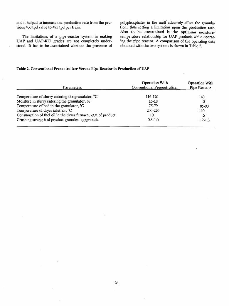
and it helped to increase the.production rate from the previous 400 tpd value to 425 tpd per train.
The limitations of a pipe-reactor system in makingUAP and UAP-KCI grades are not completely understood. It has to be ascertained whether the presence of
polyphosphates in the melt" adversely affect the granulation, thus setting a limitation upon the production rate.Also to be ascertained is the optimum moisturetemperature relationship for UAP products while operating the pipe reactor. A comparison of the operating dataobtained with the two systems is shown in Table 2.
Table 2. Conventional Preneutralizer Versus Pipe Reactor in Production of UAP
Parameters
Temperature of slurry entering the granulator, °CMoisture in slurry entering the granulator, %Temperature of bed in the granulator, °CTemperature of dryer inlet air, °CConsumption of fuel oil in the dryer furnace, kg/t of productCrushing strength of product granules, kg/granule
26
Operation WithConventional Preneutralizer
116-12016-1875-79
200-22010
0.8-1.0
Operation WithPipe Reactor
1405
85-90110
51.2-1.3

Production of CODlplex Fertilizers - An OperatingExperience in India
T. J. Joseph and T. A. Sankaran1
In addition to the above products, a 50,000-tpycaprolactam and 225,000-tpy ammonium sulfate plant isscheduled for commissioning in late 1990.
plant of the forties, FACT has through the years growninto a large multiproduct, multidivisional corporation inthe public sector. Production capacities of the corporationtoday are as follows:
The parent manufacturing unit of FACT is located atUdyogamandal, known as Udyogamandal Division. TheCochin Division, situated at Ambalamedu, is the secondmanufacturing division of FACT. Phase I of the divisionwent into commercial production in 1973 and has facilitiesto produce 198,000 tpy ammonia and 333,000 tpy urea.Phase II, which was commissioned in 1976, has facilities toproduce 330,000 tpy sulfuric acid, 115,000 tpy phosphoricacid (P20S), and 485,000 tpy complex (NP and NPK)fertilizers.
310,200580,800148,000198,00024,75049,500
330,000633,50070,000
(tonnes)Annual CapacityProducts
AmmoniaSulfuric acidPhosphoric acidAmmonium sulfateAmmonium chlorideSingle superphosphateUreaFactomfos 20-20-0 and DAP 18-46-0NPK mixtures
T. A. Sankaran
Introduction
Abstract
A fertilizer granulation plant consisting of two trains ofequipment, each with a capacity of about 800 tpd based onthe Tennessee Valley Authority (TVA) rotary granulatorprocess, was built and operated by Fertilisers andChemicals Travancore Limited (FACT). The plant is located at Cochin, India. Although original plans includedproduction of high-urea grades such as 17-17-17 and28-28-0, extreme difficulties were encountered with thesegrades due largely to their high hygroscopicity and thelack of dehumidification in the very humid production andstorage areas. After 5 years of unsuccessful operation(1979-83), the high-urea grades were abandoned andproduction was limited to diammonium phosphate(18-46-0) and ammonium sulfate-based 20-20-0. Since thechangeover, production has been highly successful and theeconomics of the plant have been greatly improved.
The Fertilisers and Chemicals Travancore Limitedorganization, popularly known as FACT, located in KeralaState in South India, pioneered the Indian fertilizer industry by setting up the rust nitrogenous fertilizer factoryin the country in 1944. From a single-product fertilizer
1. Deputy General Manager (Technical), The Fertilisers and ChemicalsTravancore Limited (FACf) - India and Plant Manager (NPK), FACTCochin Division - India, respectively.
The complex fertilizer plant was designed to producevarious grades of NPK fertilizers· such as 17-17-17,28-28-0, 14-28-14, 18-46-0, 24-12-12, 11-22-22, and 0-46-0in two trains, each having a capacity of 40 to 46 tphdepending on the grade produced. The total installedcapacity was 485,000 tpy. The plant, designed by WellmanLord/Davy Power Gas Inc., U.S.A., employs thewell-known TVA granulation process. The detailed
27
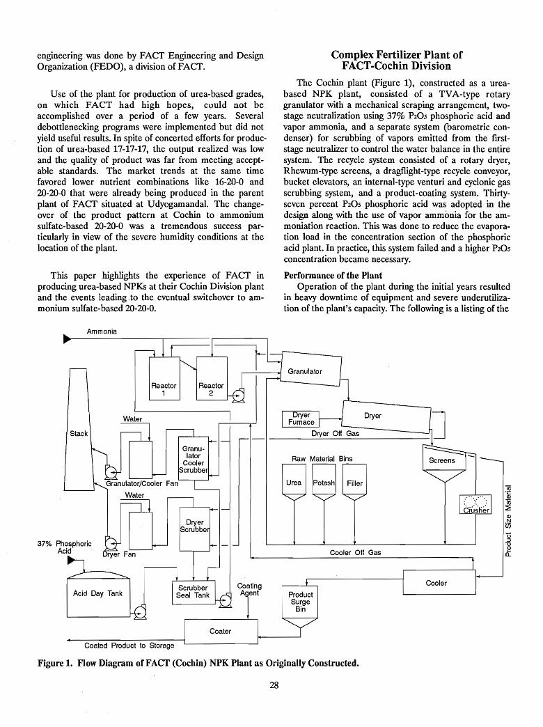
engineering was done by FACf Engineering and DesignOrganization (FEDO), a division of FACf.
Use of the plant for production of urea-based grades,on which FACT had high hopes, could not beaccomplished over a period of a few years. Severaldebottlenecking programs were implemented but did notyield useful results. In spite of concerted efforts for production of urea-based 17-17-17, the output realized was lowand the quality of product was far from meeting acceptable standards. The market trends at the same timefavored lower nutrient combinations like 16-20-0 and20-20-0 that were already being produced in the parentplant of FACf situated at Udyogamandal. The changeover of the product pattern at Cochin to ammoniumsulfate-based 20-20-0 was a tremendous success particularly in view of the severe humidity conditions at thelocation of the plant.
This paper highlights the experience of FACf inproducing urea-based NPKs at their Cochin Division plantand the events leading.to the eventual switchover to ammonium sulfate-based 20-20-0.
Complex Fertilizer Plant ofFACT-Cocbin Division
The Cochin plant (Figure 1), constructed as a ureabased NPK plant, consisted of a TVA-type rotarygranulator with a mechanical scraping arrangement, twostage neutralization using 37% P20S phosphoric acid andvapor ammonia, and a separate system (barometric condenser) for scrubbing of vapors emitted from the firststage neutralizer to control the water balance in the entiresystem. The recycle system consisted of a rotary dryer,Rhewum-type screens, a dragflight-type recycle conveyor,bucket elevators, an internal-type venturi and cyclonic gasscrubbing system, and a product-coating system. Thirtyseven percent P20S phosphoric acid was adopted in thedesign along with the use of vapor ammonia for the ammoniation reaction. This was done to reduce the evaporation load in the concentration section of the phosphoricacid plant. In practice, this system failed and a higher P20Sconcentration became necessary.
Performance of the PlantOperation of the plant during the initial years resulted
in heavy downtime of equipment and severe underutilization of the plant's capacity. The following is a listing of the
Ammonia
..(.)
::J"'0ea..
Cooler
Dryer
Cooler Off Gas
ProductSurge
Bin
Urea Potash Filler
Dryer Off Gas
Raw Material Bins
CoatingA ent
Coater
Reactor2
Acid Day Tank
Coated Product to Storage
Reactor1
Stack
37% PhosphoricAcid
Figure 1. Flow Diagram of FACT (Cochin) NPK Plant as Originally Constructed.
28
problems encountered in stabilizing production and actions taken for debottlenecking.
Poor Plant Layout-The layout of the plant was toocongested for easy maintenance and thus contributed toincreased downtime of the plant. The poor layout, in spiteof no dearth of space, was a major bottleneck beyondrectification.
Reactors - The following problems were encountered:
1. Failure of reactor brick lining - Reactors wereoriginally constructed of rubber-lined mild steel withbrick lining. Failure of the acid-proof brick lining inthe reactor caused frequent stoppages of the plant toclear the brick pieces that choked the slurry lines andnozzles. Due to damage to the reactor internals, theslurry pumps were also frequently plugged with debris.
2. Slurry overflow-There were two reactors for reactingacid with ammonia. Frequent overflow of slurry fromthe No.1 reactor due to mole ratio upsets (thickening)that prevented the flow of slurry to the No.2 reactor(through a launder) caused loss of slurry and requiredelaborate cleaning. The overflow was also aggravatedby heavy foaming in the reactor.
A single-stage stainless reactor without acidproof lining was eventually provided in place of thetwo-stage reactor system. This helped to overcome thelaunder overflow problem and eliminated completelythe choking of slurry lines and nozzles. The barometriccondenser originally used for the condensation of firststage reactor vapor was removed because it was inefficient and created a pollution problem.
3. Foaming - Foaming in the reactors and scrubber-sealtank resulted in false level and pumping rate indications. The foaming problem experienced was mainlydue to the presence of urea in the system. A fewdefoamers were tried but not with success.
Poor Granulation - While making the 17-17-17 grade,granulation was found to be very poor due to unsteadyslurry feed, low temperature of the slurry, and the addition of coarse potash and sand. This resulted in too muchfme material in the system which ultimately found its wayinto the final product.
Scrubber Liquor Mole Ratio - Due to unsteady operating conditions, the mole ratio would rise and result· in theformation of solid phosphates. Scrubber distributionnozzles and airflow channels inside the scrubbers pluggedvery often, affecting the scrubber efficiency. Longdowntimes were required for cleaning the scrubberinternals.
29
Acid Strength - The 37% P20S phosphoric acid systemposed granulation problems for the production of 17-17-17and 18-46-0 due to the low temperature (high moisture) ofthe slurry.
Gran ulator - The following problems wereencountered:
1. Scraper - At least twice a day, the plant had to bestopped for cleaning of heavy accumulations of hardsolids and lumps from the mechanical scraper, supports, and interior of the granulator shell. Themechanical scraper was removed, and the shell wasfitted with rubber panels. This was found to be effective, and frequency of cleaning was decreased.
2. Ammonia sparger - The original ammonia sparger located below the bed of material in the granulator,though providing uniform distribution, did not workwell because the buildup of material on the supportsand on the shell caused the supports to fail. Hence, thesubmerged sparger was replaced with dip pipes whichoffered less resistance to material movement inside thegranulator.
Choking of Chutes and Cyclones - Choking of variouschutes due to the congested plant layout, inadequatesizing, and mixing of moist fumes with dust-laden aircaused a major problem. Vent ducts provided for therecycle equipment were frequently getting choked as someportions of these ducts were running horizontally.
Screens - The double-decked Rhewum-typeelectromagnetic vibrating screens posed severe limitationsdue to blinding. The screens were modified by increasing .the space between the two decks to have better accessibility for manual cleaning. The electromagnetic vibratorswere replaced with a motor vibration arrangement. Subsequently, these units were replaced with single-deckscreens, and this arrangement is giving good performance.
Burners -The lower temperature required by theurea-based grades could not be maintained because of thepoor turn-down range of the dryer burner system; consequently, fusing of material in the dryer occurred frequently. This resulted in long shutdowns and the need forstrenuous manual labor for cleaning the dryer and otherdownstream chutes and equipment.
Unsteady Urea Feed Rate-The formation of lumps inthe urea bins prevented the free flow of urea through theweigh feeders; the resulting erratic feed rates adversely affected the product analysis.
Spillage Recovery- Due to the very hygroscopic natureof the urea grades, any spillage of material or the escape
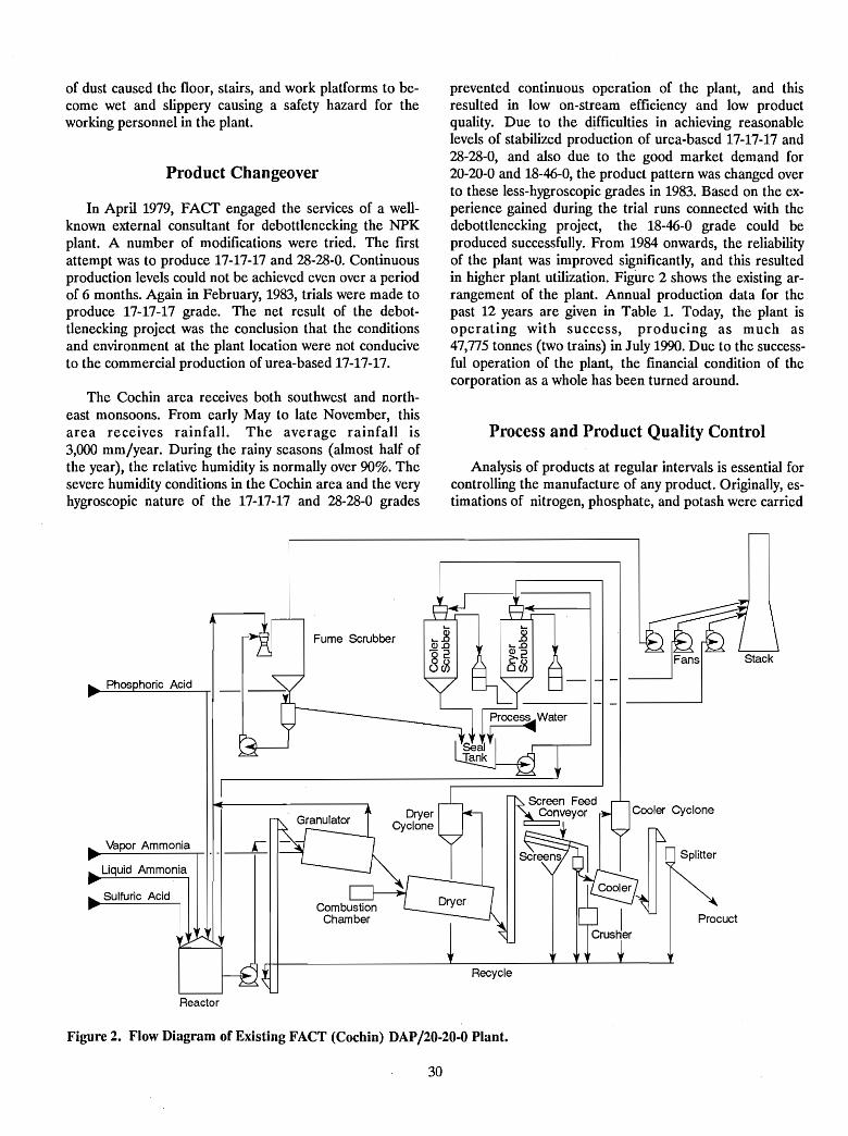
of dust caused the floor, stairs, and work platforms to become wet and slippery causing a safety hazard for theworking personnel in the plant.
Product Changeover
In Apri11979, FACf engaged the services of a wellknown external consultant for debottlenecking the NPKplant. A number of modifications were tried. The frrstattempt was to produce 17-17-17 and 28-28-0. Continuousproduction levels could not be achieved even over a periodof 6 months. Again in February, 1983, trials were made toproduce 17-17-17 grade. The net result of the debottlenecking project was the conclusion that the conditionsand environment at the plant location were not conduciveto the commercial production of urea-based 17-17-17.
The Cochin area receives both southwest and northeast monsoons. From early May to late November, thisarea receives rainfall. The average rainfall is3,000 mm/year. During the rainy seasons (almost half ofthe year), the relative humidity is normally over 90%. Thesevere humidity conditions in the Cochin area and the veryhygroscopic nature of the 17-17-17 and 28-28-0 grades
prevented continuous operation of the plant, and thisresulted in low on-stream efficiency and low productquality. Due to the d~fficulties in achieving reasonablelevels of stabilized production of urea-based 17-17-17 and28-28-0, and also due to the good market demand for20-20-0 and 18-46-0, the product pattern was changed overto these less-hygroscopic grades in 1983. Based on the experience gained during the trial runs connected with thedebottlenecking project, the 18-46-0 grade could beproduced successfully. From 1984 onwards, the reliabilityof the plant was improved significantly, and this resultedin higher plant utilization. Figure 2 shows the existing arrangement of the plant. Annual production data for thepast 12 years are given in Table 1. Today, the plant isoperating with success, producing as much as47,775 tonnes (two trains) in July 1990. Due to the successful operation of the plant, the financial condition of thecorporation as a whole has been turned around.
Process and Product Quality Control
Analysis of products at regular intervals is essential forcontrolling the manufacture of any product. Originally, estimations of nitrogen, phosphate, and potash were carried
Vapor Ammonia
Liquid Ammonia
Fume SCrubber
Cooler Cyclone
Procuct
Recycle
Reactor
Figure 2. Flow Diagram of Existing FACT (Cochin) DAP/20-20-0 Plant.
30
Table 1. Annual Production of NP and NPK Fertilizers at FACT, Cochin Division (Total for Two Production Trains)
Before Product Changeover
1978/79 1979/80 1980/81 1981/82 1982/83
- - - - - - - - - - - - - - - - (tpy product) - - - - - - - - - - - - - - - -
After Product Changeover
1983/84 1984/85 1985/86 1986/87 1987/88 1988/89 1989/90
- - - - - -'- - - - - - - - - - - - - - - - - - - - (tpy product) - - - - - - - - - - - - - - - - - - - - - - --
103,690 99,406 198,414 151,869 179,233 214,700 333,262 323,979a 402,700 424,366 476,005 363,065b
a. Production was affected by the decommissioning of the imported ammonia storage installation for inspection.
b. The production during the year was affected by the scarcity of imported raw materials, particularly ammonia and phosphoric acid.
out using conventional laboratory manual methods. Sincethese methods are very elaborate, time consuming, andtedious, the data from the analysis were available too lateand were not of much use in process control. Nitrogen wasestimated as total nitrogen by the Kjeldahl digestionmethod. This required a minimum of 2 h. Total P20S wasestimated volumetrically after precipitating as phosphomolybdate; this took about 1~ h. Potash estimation bythe perchloric acid method required much more time.Therefore, appropriate process instrumentation for morerapid analysis was found essential. An autoanalyzercapable of hourly analysis of nitrogen (ammoniacalnitrogen and urea nitrogen), total phosphate, and potashwas installed in 1979. One key feature of this instrument isits capability to separately determine ammoniacal nitrogenand urea nitrogen, which was not possible in conventionalmethods. With the switchover of the product pattern to20-20-0 and 18-46-0, the potash channel of the analyzerwas idle. As the production of 20-20-0 stabilized, the needto estimate the sulfate content in the product was increasingly felt. The unutilized potash channel therefore wasmodified, making it suitable to measure the colorimetricresponse to low-level barium sulfate turbidity, for the estimation of the sulfate content.
Environmental Control
The pollution control facilities were made adequate tomeet the environmental regulations. A plant for treatingthe effluents was set up after elaborate studies. Theaqueous effluent containing ammoniacal nitrogen,fluorides, and phosphates as pollutants is collected in anequalization tank and treated with requisite quantities oflime in a flash mixer attached to a clariflocculator, inwhich the fluorides and phosphates are converted into insoluble calcium salts. The sludge containing these salts iswithdrawn from the clariflocculator and filtered to removethe solids. The partially treated effluents leaving theclariflocculator are stripped to remove ammonia and thenneutralized before being released.
31
The original scrubber design called for combined scrubbing of the fumes evolved from the reactor and dustevolved from various equipment. An internalventuri/cyclonic-type scrubber was used. This system wasnot efficient because the mixing of dust and fumes,resulted in plugging; this led to inefficient removal offumes from the reactor. This scrubbing system was extensively modified. A new fume scrubber consisting of an external venturi/cyclonic-type unit now provides a clean environment in the plant. Fumes from the reactor and thegranulator are scrubbed with 20%-25% phosphoric acid.The design of the venturi (located outside the cyclonicseparator) provides easy accessibility for maintenance andfor varying the throat opening in conformity with the plantload conditions. The NH3:H3P04 mole ratio of the liquorcirculated through the scrubber is maintained at optimumconditions. A bleed stream from the primary circulationloop is routed to the reactor.
Factors to be Considered in theSelection of Grades and in Designing
Complex Fertilizer Plants
The experience of FACT provides the following vitalinformation for the selection of grades and for designingcomplex fertilizer plants.
1. The 17-17-17 grade and similar urea-based gradesare difficult to handle under high-humidity conditions due to their low critical relative humidity. Onthe other hand, ammonium sulfate-based grades thatare less hygroscopic are well suited for such humidlocations.
2. The addition of potash, especially to urea-basedgrades, caused major problems due to an increase inthe hygroscopic properties of the NPK product(lowering of critical humidity). Therefore, grades containing potash are not desirable for production inlocations where the relative humidity is high.
3. When deciding the layout for complex fertilizerplants, adequate floor space and head room tohandle spillages and for maintenance of equipmentshould be ensured. Smooth gradients with the leastnumber of bends for chutes and ducts are essential.Care should also be given to provide adequate spaceand provisions for cleanout and inspection openingsto facilitate cleaning and maintenance of variousequipment such as scrubbers, cyclones, feed chutes,and screens.
4. The accepted practices for choosing reliable andproven equipment should be insisted upon.
5. Analysis of products at regular intervals is essentialin controlling the production of complex fertilizers.In this context, it is necessary to provide automaticanalyzers for all the essential elements in theproducts.
6. The recycle system should have adequate excesscapacity to handle fluctuations in production.
7. Separate scrubbing systems for fume and d~st shouldbe provided.
8. Protection against phosphoric acid spills soaking intothe ground must be ensured to avoid any reaction ofacid with the soil and consequent problems withground swelling and foundation failures.
9. Good design and construction practices offering theleast possibility for entry of moisture into the plantarea as well as good exhaust systems are essential.
10. The recovery system for spillages should be fast andefficient.
Expansion of Plant Capacity
FACT is now considering expansion of the NPK plantcapacity by incorporating a pipe reactor. The major thrustis on decreasing the recycle ratio while aiming at energyconservation and increased production. With the installation of the pipe reactor, the plant capacity is estimated togo up to 400,000 tpy of 20-20-0 and 184,000 tpy of DAP(584,000 tpy total for two trains), against the present totalcapacity (two trains)' of 485,000 tpy.
32
Conclusion
The experience of FACT in its operation of complexfertilizer plants, shows that it is advantageous to adoptammonium sulfate-based formulations in plants located inareas of high humidity. If urea-based NPK formulationsare to be chosen, an elaborate dehumidification systemhas to be provided for the production, bagging, andstorage areas to maintain quality of products and continuity of production.
Bibliography
1. Ramasubbu, P. K., and N. Natarajan. 1988."Optimizing Formulations of Complex FertilizerGrades," Proceedings of NPK Workshop, Madras.
2. Ramasubbu, P. K., and N. Natarajan. 1986. "ImprovingPerformance of Complex Fertilizer Plants," FertilizerNews, Vol. 31, No. 12 (59-65).
3. Kulandai Raj., D. 1979. "Performance of NPK Plant atFACT, Cochin," FAI Seminar Proceedings.
4. Schultz, J. J. 1989. "Production of Granular NPKs inAmmonium Phosphate Plants - Some ImportantDifferences," Technical Bulletin T-36, InternationalFertilizer Development Center, Muscle Shoals,Alabama.
Illlproving Productivity in NPK Granulation Plants - NAFCON(Nigeria) Experience
T. R. Ramaswami1
Abstract
The National Fertilizer Company of Nigeria Limited(NAFCON) complex, the fust of its kind in Nigeria, consists of a single-train ammonia and urea plant and an NPKgranulation plant. The production of various NPK gradesis geared toward local consumption. A continuous effortis being made to improve the productivity of the NPKgranulation unit. NAFCDN's fust 2 years of operationalexperiences are discussed. The various plant modificationscarried out during this period to improve productivity arealso discussed including the addition of granular urea tothe process after the granulation, drying, and coolingsteps. The performance of major equipment items used inthe granulation unit is discussed. This paper also explainsthe basic requirements needed to improve on-stream efficiency giving specific reference to good maintenancepractices, adequate inventory of spare parts, andavailability of raw materials.
Introduction
The National Fertilizer Company of Nigeria Limited(NAFCON) is the first and only nitrogenous fertilizer complex in Nigeria, manufacturing 1,000 tpd of ammonia,1,500 tpd of urea, and 1,000 tpd of different grades ofNPK. This complex is located at Dnne, near Port Harcourt in Rivers State. NAFCDN is a joint venture betweenthe Federal Government of Nigeria and the M.W. KelloggCompany of Houston, Texas (V.SA.).
With the growing population, particularly in ThirdWorld countries, the demand for fertilizer is expected tosteadily increase to meet the increased demand for foodproduction. Although the phosphatic fertilizer industry'sgrowth is not as significant as that of the nitrogenous fertilizer industry, complex NPK granular fertilizers, by theirown merit, are popular and preferred by farmers wherebalanced plant nutrient application is required. Modernsingle-train NPK plants, such as the NAFCDN plant, arerated to produce about 1,000 tpd product.
1. NPK Plant Superintendent, National Fertilizer Company of Nigeria
Limited (NAFCON) - Nigeria.
33
NAFCON Experience inImproving NPK Plant Productivity
NAFCON NPK Plant-Salient FeaturesThe NPK plant is a single-train conventional slurry
granulation plant suitable for manufacturing DAP andseveral NPK grades. The preneutralizer (reactor) is an unlined Type 317L stainless steel vessel 12 ft in diameter and20 ft tall. The granulator drum is 11 ft in diameter and22 ft long. Its interior is fitted with loose rubber paneling.
The dryer is a cocurrent unit, 12 ft in diameter x 90 ftlong, and is driven by a two-speed motor. It is heated withnatural gas fuel. Single-deck screens are provided whichare quite efficient. The fmes (recycle) conveyor in theplant is a 72-inch wide, inclined belt conveyor. Bucketelevators used in the plant are equipped with the wellknown Jeffry chain. A fluidized bed cooler is used for cooling the product. The cooling mediuln used in this cooler isconditioned (chilled) air. Ammonia is used as therefrigerant for cooling the air, and the ammonia vapor generated is used in the NPK process. Two venturi-typecyclonic scrubbers are used - one for dust and fumes andthe other for the dryer offgases. Variable-speed productscreen feeders are used to regulate and control theproduct offtake and the recycle load. This system helps in
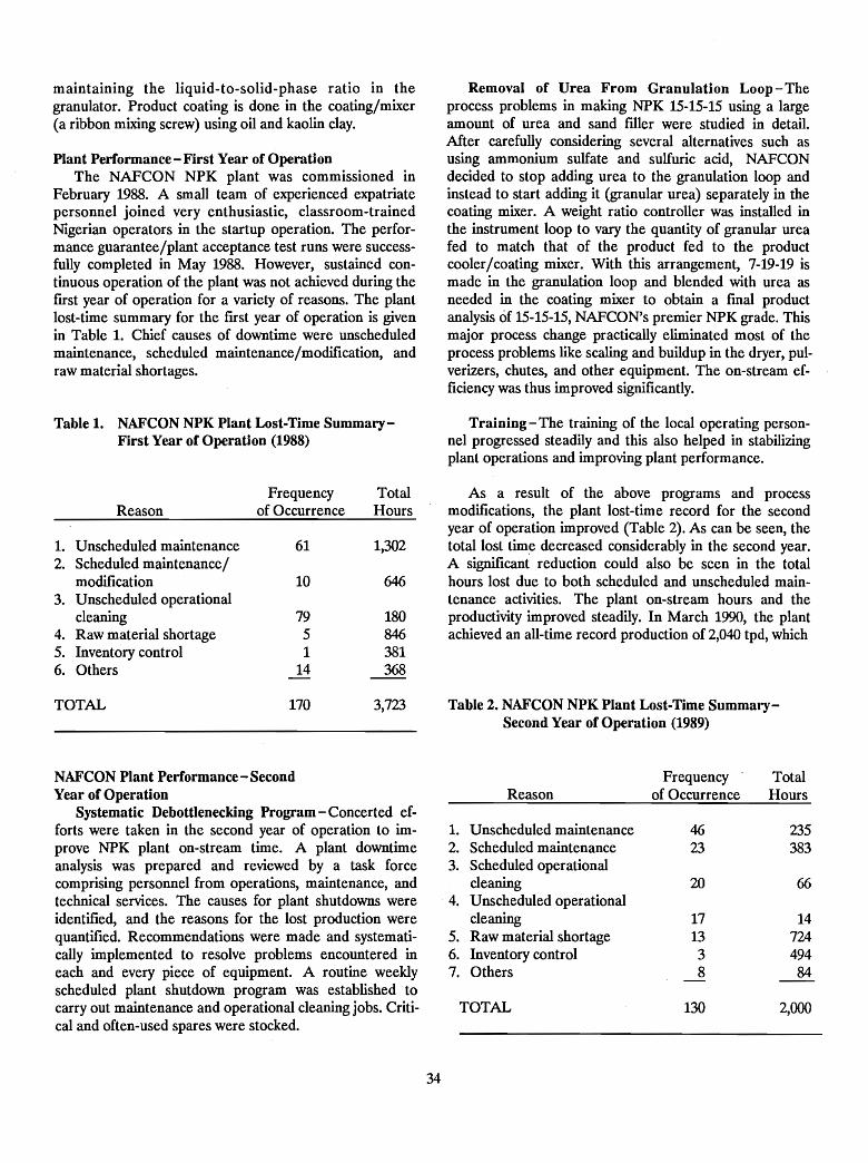
maintaining the liquid-to-solid-phase ratio in thegranulator. Product coating is done in the coating/mixer(a ribbon mixing screw) using oil and kaolin clay.
Plant Performance-First Year of OperationThe NAFCON NPK plant was commissioned in
February 1988. A small team of experienced expatriatepersonnel joined very enthusiastic, classroom-trainedNigerian operators in the startup operation. The performance guarantee/plant acceptance test runs were successfully completed in May 1988. However, sustained continuous operation of the plant was not achieved during thefrrst year of operation for a variety of reasons. The plantlost-time summary for the first year of operation is givenin Table 1. Chief causes of downtime were unscheduledmaintenance, scheduled maintenance/modification, andraw material shortages.
Table 1. NAFCON NPK Plant Lost-Time Summary-First Year of Operation (1988)
Frequency TotalReason of Occurrence Hours
1. Unscheduled maintenance 61 1,3022. Scheduled maintenance/
modification 10 6463. Unscheduled operational
cleaning 79 1804. Raw material shortage 5 8465. Inventory control 1 3816. Others 14 368
TOTAL 170 3,723
NAFCON Plant Performance - SecondYear of Operation
Systematic Debottlenecking Program - Concerted efforts were taken in the second year of operation to improve NPK plant on-stream time. A plant downtimeanalysis was prepared and reviewed by a task forcecomprising personnel from operations, maintenance, andtechnical services. The causes for plant shutdowns wereidentified, and the reasons for the lost production werequantified. Recommendations were made and systematically implemented to resolve problems encountered ineach and every piece of equipment. A routine weeklyscheduled plant shutdown program was established tocarry out maintenance and operational cleaning jobs. Critical and often-used spares were stocked.
34
Removal of Urea From Granulation Loop - Theprocess problems in making NPK 15-15-15 using a largeamount of urea and sand filler were studied in detail.After carefully considering several alternatives such asusing ammonium sulfate and sulfuric acid, NAFCONdecided to stop adding urea to the granulation loop andinstead to start adding it (granular urea) separately in thecoating mixer. A weight ratio controller was installed inthe instrument loop to vary the quantity of granular ureafed to match that of the product fed to the productcooler/coating mixer. With this arrangement, 7-19-19 ismade in the granulation loop and blended with urea asneeded in the coating mixer to obtain a fmal productanalysis of 15-15-15, NAFCON's premier NPK grade. Thismajor process change practically eliminated most of theprocess problems like scaling and buildup in the dryer, pulverizers, chutes, and other equipment. The on-stream efficiency was thus improved significantly.
Training - The training of the local operating personnel progressed steadily and this also helped in stabilizingplant operations and improving plant performance.
As a result of the above programs and processmodifications, the plant lost-time record for the secondyear of operation improved (Table 2). As can be seen, thetotal lost time decreased considerably in the second year.A significant reduction could also be seen in the totalhours lost due to both scheduled and unscheduled maintenance activities. The plant on-stream hours and theproductiVity improved steadily. In March 1990, the plantachieved an all-time record production of 2,040 tpd, which
Table 2. NAFCON NPK Plant Lost-Time Summary-Second Year of Operation (1989)
Frequency TotalReason of Occurrence Hours
1. Unscheduled maintenance 46 2352. Scheduled maintenance 23 3833. Scheduled operational
cleaning 20 664. Unscheduled operational
cleaning 17 145. Raw material shortage 13 7246. Inventory control 3 4947. Others 8 84
TOTAL 130 2,000
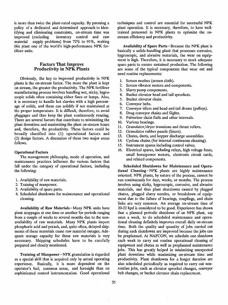
is more than twice the plant-rated capacity. By pursuing apolicy of a dedicated and determined approach to identifying and eliminating constraints, on-stream time wasimproved (excluding inventory control and rawmaterial supply problems) from 72% to 91%, makingthis plant one of the world's high-performance NPK fertilizer units.
Factors That ImproveProductivity in NPK Plants
Obviously, the key to improved productivity in NPKplants is the on-stream factor. The more the plant is kepton stream, the greater the productivity. The NPK fertilizermanufacturing process involves handling we~, sticky, hygroscopic solids often containing either fines or lumps. Also,it is necessary to handle hot slurries with a high percentage of solids, and these can solidify if not maintained atthe proper temperature. It is difficult, therefore, to avoidpluggages and thus keep the plant continuously running.There are several factors that contribute to minimizing theplant downtime and maximizing the plant on-stream hoursand, therefore, the productivity. These factors could bebroadly classified into (1) operational factors and(2) design factors. A discussion of these two major areasfollows.
Operational FactorsThe management philosophy, mode of operation, and
maintenance practices influence the various factors thatfall under the category of operational factors, includingthe following:
1. Availability of raw materials.2. Training of manpower.3. Availability of spare parts.4. Scheduled shutdowns for maintenance and operational
cleaning.
Availability of Raw Materials - Many NPK units haveplant stoppages at one time or another for periods rangingfrom a couple of weeks to several months due to the nonavailability of raw materials. Many NPK plants importphosphoric acid and potash, and, quite often, delayed shipments of these materials cause raw material outages. Adequate storage capacity for these raw materials is verynecessary. Shipping schedules have to be carefullyprepared and closely monitored.
Training of Manpower - NPK granulation is regardedas a special skill that is acquired only by actual operatingexperience. Basically, it is more dependent on theoperator's feel, common sense, and foresight than onsophisticated control instrumentation. Good operational
35
techniques and control are essential for successful NPKplant operation. It is necessary, therefore, to have welltrained personnel in NPK plants to optimize the onstream efficiency and productivity.
Availability of Spare Parts - Because the NPK plant isbasically a solids-handling plant that processes corrosive,hygroscopic, and abrasive materials, the wear on equipment is high. Therefore, it is necessary to stock adequatespare parts to ensure sustained production. The followingare some of the typical components that wear out andneed routine replacements:
1. Screen meshes (screen cloth).2. Screen vibrator motors and components.3. Slurry pump components.4. Bucket elevator head and tail sprockets.5. Bucket elevator chain.6. Conveyor belts.7. Conveyor idlers and head and tail drums (pulleys).8. Drag conveyor chains and flights.9. Pulverizer chain flails and other internals.
10. Various bearings.11. Granulator/ dryer trunnions and thrust rollers.12. Granulator rubber panels (liners).13. Chutes, ducts, and hopper discharge assemblies.14. Cyclone chains (for internal continuous cleaning).15. Instrument spares including control valves.16. Electrical spares, including relays, high voltage fuses,
small horsepower motors, electronic circuit cards,and related components.
Scheduled Shutdowns for Maintenance and Operational Cleaning - NPK plants are highly maintenanceoriented. NPK plants, by nature of the process, cannot berun continuously for days, weeks, or months. The processinvolves using sticky, hygroscopic, corrosive, and abrasivematerials, and thus plant shutdowns caused by pluggedchutes, plugged slurry nozzles, or breakdown of equipment due to the failure of bearings, couplings, and chainlinks are very common. An average on-stream time of20-22 hpd is considered to be good. Experience has shownthat a planned periodic shutdown of an NPK plant, sayonce a week, to do scheduled maintenance and operational cleaning definitely improves overall daily on-streamtime. Both the quality and quantity of jobs carried outduring such shutdowns are improved because the jobs canbe preplanned. At NAFCON, we schedule one shutdowneach week to carry out routine operational cleaning ofequipment and chutes as well as preplanned maintenancejobs. This has greatly helped in minimizing unexpectedplant downtime while maximizing on-stream time andproductivity. Plant shutdowns for a longer duration arealso scheduled periodically as required to carry out nonroutine jobs, such as elevator sprocket changes, conveyorbelt changes, or bucket elevator chain replacement.
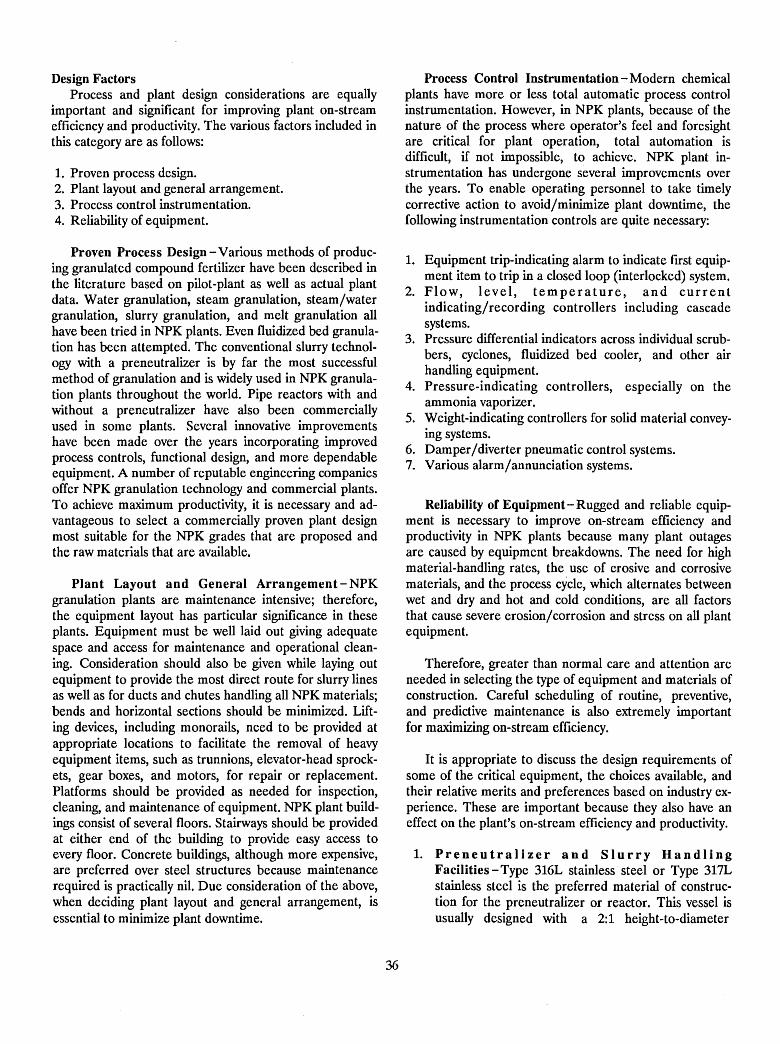
Design FactorsProcess and plant design considerations are equally
important and significant for improving plant on-streamefficiency and productivity. The various factors included inthis category are as follows:
1. Proven process design.2. Plant layout and general arrangement.3. Process control instrumentation.4. Reliability of equipment.
Proven Process Design - Various methods of producing granulated compound fertilizer have been described inthe literature based on pilot-plant as well as actual plantdata. Water granulation, steam granulation, steam/watergranulation, slurry granulation, and melt granulation allhave been tried in NPK plants. Even fluidized bed granulation has been attempted. The conventional slurry technology with a preneutralizer is by far the most successfulmethod of granulation and is widely used in NPK granulation plants throughout the world. Pipe reactors with andwithout a preneutralizer have also been commerciallyused in some plants. Several innovative improvementshave been made over the years incorporating improvedprocess controls, functional design, and more dependableequipment. A number of reputable engineering companiesoffer NPK granulation technology and commercial plants.To achieve maximum productivity, it is necessary and advantageous to select a commercially proven plant designmost suitable for the NPK grades that are proposed andthe raw materials that are available.
Plant Layout and General Arrangement - NPKgranulation plants are maintenance intensive; therefore,the equipment layout has particular significance in theseplants. Equipment must be well laid out giving adequatespace and access for maintenance and operational cleaning. Consideration should also be given while laying outequipment to provide the most direct route for slurry linesas well as for ducts and chutes handling all NPK materials;bends and horizontal sections should be minimized. Lifting devices, including monorails, need to be provided atappropriate locations to facilitate the removal of heavyequipment items, such as trunnions, elevator-head sprockets, gear boxes, and motors, for repair or replacement.Platforms should be provided as needed for inspection,cleaning, and maintenance of equipment. NPK plant buildings consist of several floors. Stairways should be providedat either end of the building to provide easy access toevery floor. Concrete buildings, although more expensive,are preferred over steel structures because maintenancerequired is practically nil. Due consideration of the above,when deciding plant layout and general arrangement, isessential to minimize plant downtime.
36
Process Control Instrumentation - Modern chemicalplants have more or less total automatic process controlinstrumentation. However, in NPK plants, because of thenature of the process where operator's feel and foresightare critical for plant operation, total automation isdifficult, if not impossible, to achieve. NPK plant instrumentation has undergone several improvements overthe years. To enable operating personnel to take timelycorrective action to avoid/minimize plant downtime, thefollowing instrumentation controls are quite necessary:
1. Equipment trip-indicating alarm to indicate first equipment item to trip in a closed loop (interlocked) system.
2. Flo w, I eve I , t e m per a t u r e , and cur r e n tindicating/recording controllers including cascadesystems.
3. Pressure differential indicators across individual scrubbers, cyclones, fluidized bed cooler, and other airhandling equipment.
4. Pressure-indicating controllers, especially on theammonia vaporizer.
5. Weight-indicating controllers for solid material conveying systems.
6. Damper/diverter pneumatic control systems.7. Various alarm/annunciation systems.
Reliability of Equipment - Rugged and reliable equipment is necessary to improve on-stream efficiency andproductivity in NPK plants because many plant outagesare caused by equipment breakdowns. The need for highmaterial-handling rates, the use of erosive and corrosivematerials, and the process cycle, which alternates betweenwet and dry and hot and cold conditions, are all factorsthat cause severe erosion/corrosion and stress on all plantequipment.
Therefore, greater than normal care and attention areneeded in selecting the type of equipment and materials ofconstruction. Careful scheduling of routine, preventive,and predictive maintenance is also extremely importantfor maximizing on-stream efficiency.
It is appropriate to discuss the design requirements ofsome of the critical equipment, the choices available, andtheir relative merits and preferences based on industry experience. These are important because they also have aneffect on the plant's on-stream efficiency and productivity.
1. Preneutralizer and Slurry HandlingFacilities - Type 316L stainless· steel or Type 317Lstainless steel is the preferred material of construction for the preneutralizer or reactor. This vessel isusually designed with a 2:1 height-to-diameter
ratio and a normal operating level of 50%. Processupsets will be minimized if the freeboard capacity ishigh. Slurry lines to the granulator should be by themost direct route with a minimum number of bends.
2. Granulator - Loose rubber paneling coupled with thefacility to reverse the granulator is used in manyplants. Mechanical scrapers are usually a problem.The granulator discharge chute should be a singleduct sufficiently large anq as short and nearly verticalas possible.
3. Dryer - A two-speed motor should be specified foreasy change of dryer speed as needed for urea-basedNPK grades and for other grades to increase ordecrease dryer retention time. The lack of properrigging/lifting devices for the dryer motor, gear-box,trunnions, and other heavy components will increasemaintenance downtime of the plant.
4. Elevators - Slow-speed double-strand (chain) bucketelevators are preferred. The wear of bucket elevatorchains and sprockets depends on the NPK grademanufactured and the type of raw materials used.Periodic inspection and renewal of head and tailsprockets will improve the chain life and will minimize breakdowns.
5. Screens and Screen Feeders - Single-deck screenshave tremendous maintenance and performance ad-
37
vantages. A single-deck screen arrangementeliminates the need to have a drag-type conveyor tofeed the screens. Such a conveyor usually requireshigh maintenance. Product screen feeders consistingof variable-speed belt conveyors ensure that only therequired amount of product is screened and that maximum screening efficiency is achieved.
6. Drag Feeders Versus Belt Conveyors - Drag feedersare high-maintenance equipment. At NAFCON, a72-inch-wide belt conveyor is used for the fines conveyor, replacing the more commonly used dragfeeder for this service. The performance of this beltconveyor is very good and is more reliable than thatof the drag feeder.
7. Raw Material Bins and Weigh Feeders - In a typicalurea-based NPK plant, there are at least three rawmaterial bins equipped with belt-type weighfeeders - one each for urea, potash, and filler. Manynew plants have additional bins and feeders asspares. Having at least one additional bin with a beltweigh feeder is very advantageous and will almost certainly increase plant on-stream time. The spare unitcan also be used to feed monoammonium phosphateor some other raw material into the system ifneeded. Wide belts (at least 36-inches) on weighfeeders are preferred over narrow belts to minimizespillage.
8. Screw Conveyors - It is better to avoid screw conveyors, especially for hygroscopic NPK materials.Their availability factor is limited. At NAFCON, thedust conveyor that carries cyclone dust to thegranulator was initially a screw conveyor. This unitfailed frequently and was replaced with a belt conveyor which is now running practically trouble free.
9. Fluidized Bed Cooler- Maintenance required is verylimited in fluidized bed coolers. However, operational cleaning time is high in fluidized bed coolersbecause the hygroscopic fertilizer material clogs theair distribution screen mesh. Keeping the distributionscreen dry and clean is a problem.
10. Chute and 'Ducts - A 55° valley angle is the standardused in this industry for chutes and hoppers. A 70°angle is required for handling dust. Chutes and ductsshould preferably be nearly vertical with a minimumof elbows or bends. It is also necessary to provideclean-out doors at all turns, at each floor level, andpreferably about every 10 ft of length for longerchutes. Attention must be paid also to providing access for the clean-out doors at different locations. Alot of cleaning time can be saved with properly
designed chutes, ducts, clean-out doors, and accessplatforms.
Conclusion
The NPK plant process is not complex, but operationof a solids-handling plant has always been difficult. Selection of a proven design with reliable equipment and a
well-planned equipment layout are basic requirements fora high on-stream efficiency. A good preventive andpredictive maintenance program together with theavailability of adequate spare parts and raw materials aresome of the essential factors that contribute to increasedon-stream efficiency. Additionally, in each NPK plant, onthe basis of operating experience gained, changes andmodifications may have to be made to optimize plant onstream efficiency and productivity.
Bibliography
1. Aranuach-Alam, P. N., et al. 1986. "Process andMaterials Problems in NPK Plants in FertilizerIndustry," Tutorial Symposium on Corrosion Controlin Fertilizer Industries, CECRI, Karaidudi, India.
2. Arunachalam, P. N., F. R. Keeshan, D. W. Leyson, andW. E. Potts. 1981. "Urea-DAP-NPK Granulation,"American Chemical Society, New York, New York.
3. Keshavamurthy, G. S. 1978. "Optimization of CapacityUtilization in NPK Granulation Plants," FAI Seminar,New Delhi, India.
4. Kulp, R. L., E. R. Landgraf, and D. W. Leyshon. 1973."Production of Urea - DAP Fertilizers by the
38
Dorr-Oliver Slurry Process," American ChemicalSociety, Chicago, Illinois.
5. Leyshon, D. W., and I. S. Mangat. 1976. "Innovationsin Slurry Process Granulation Plants," ISMA, TheHague, Netherlands.
6. Ramaswami, T. R. 1984. "Quality Control of ComplexFertilizer," FAI Seminar, Goa, India.
7. Vasani, J. S., and D. W. Leyshon. 1985. "Manufactureof Urea-DAP-Based NPK Products in DevelopingCountries," The Fertilizer Industry Round Table,October 1985.
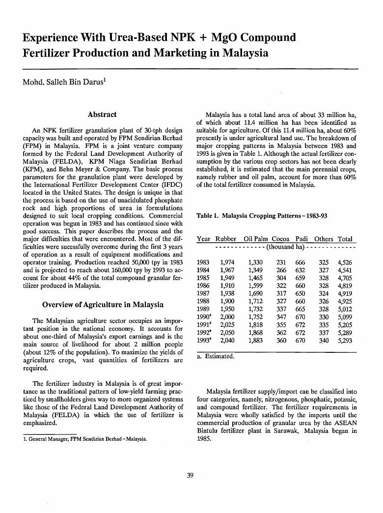
Experience With Urea-Based NPK + MgO CompoundFertilizer Production and Marketing in Malaysia
Mohd. Salleh Bin Darns!
Abstract
An NPK fertilizer granulation plant of 3O-tph designcapacity was built and operated by FPM Sendirian Berhad(FPM) in Malaysia. FPM is a joint venture companyformed by the Federal Land Development Authority ofMalaysia (FELDA), KPM Niaga Sendirian Berhad(KPM), and Behn Meyer & Company. The basic processparameters for the granulation plant were developed bythe International Fertilizer Development Center (IFDC)located in the United States. The design is unique in thatthe process is based on the use of unacidulated phosphaterock and high proportions of urea in formulationsdesigned to suit local cropping conditions. Commercialoperation was begun in 1983 and has continued since withgood success. This paper describes the process and themajor difficulties that were encountered. Most of the difficulties were sucessfully overcome during the first 3 yearsof operation as a result of equipment modifications andoperator training. Production reached 50,000 tpy in 1983and is projected to reach about 160,000 tpy by 1993 to account for about 44% of the total compound granular fertilizer produced in Malaysia.
Overview ofAgriculture in Malaysia
The Malaysian agriculture sector occupies an important position in the national economy. It accounts forabout one-third of Malaysia's export earnings and is themain source of livelihood for about 2 million people(about 12% of the population). To maximize the yields ofagriculture crops, vast quantities of fertilizers arerequired.
The fertilizer industry in Malaysia is of great importance as the traditional pattern of low-yield farming practiced by smallholders gives way to more organized systemslike those of the Federal Land Development Authority ofMalaysia (FELDA) in which the use of fertilizer isemphasized.
1. General Manager, FPM Sendirian Berhad - Malaysia.
39
Malaysia has a total. land area of about 33 million ha,of which about 11.4 million ha has been identified assuitable for agriculture. Of this 11.4 million ha, about 60%presently is under agricultural land use. The breakdown ofmajor cropping patterns in Malaysia between 1983 and1993 is given in Table 1. Although the actual fertilizer consumption by the various crop sectors has not been clearlyestablished, it is estimated that the main perennial crops,namely rubber and oil palm, account for more than 60%of the total fertilizer consumed in Malaysia.
Table 1. Malaysia Cropping Patterns -1983-93
Year Rubber Oil Palm Cocoa Padi Others Total- - - - - - - - - - - - - (thousand ha) - - - - - - - - - - - - -
1983 1,974 1,330 231 666 325 4,5261984 1,967 1,349 266 632 327 4,5411985 1,949 1,465 304 659 328 4,7051986 1,910 1,599 322 660 328 4,8191987 1,938 1,690 317 650 324 4,9191988 1,900 1,712 327 660 326 4,9251989 1,950 1,732 337 665 328 5,01219903 2,000 1,752 347 670 330 5,09919913 2,025 1,818 355 672 335 5,20519928 2,050 1,868 362 672 337 5,28919933 2,040 1,883 360 670 3:4(> 5,293
a. Estimated.
Malaysia fertilizer supply/import can be classified intofour categories, namely, nitrogenous, phosphatic, potassic,and compound fertilizer. The fertilizer requirements inMalaysia were wholly satisfied by the imports until thecommercial production of granular urea by the ASEANBintulu fertilizer plant in Sarawak, Malaysia began in1985.
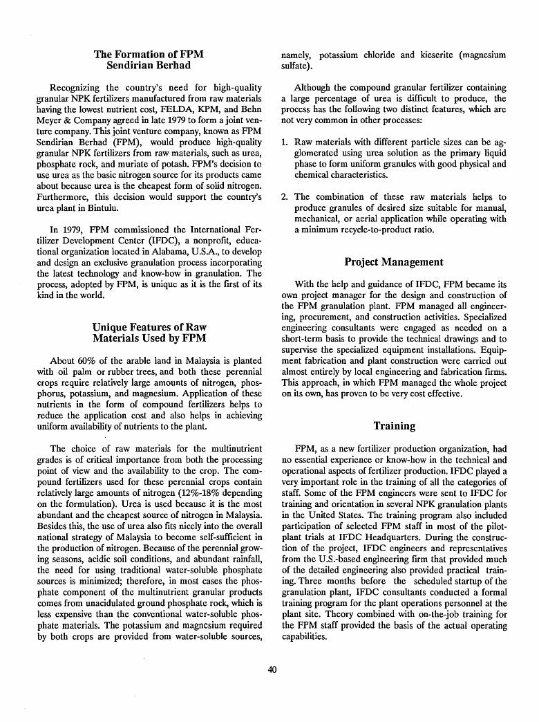
The Formation of FPMSendirian Berhad
Recognizing the country's need for high-qualitygranular NPK fertilizers manufactured from raw materialshaving the lowest nutrient cost, FELDA, KPM, and BehnMeyer & Company agreed in late 1979 to form a joint venture company. This joint venture company, known as FPMSendirian Berhad (FPM), would produce high-qualitygranular NPK fertilizers from raw materials, such as urea,phosphate rock, and muriate of potash. FPM's decision touse urea as the basic nitrogen source for its products cameabout because urea is the cheapest form of solid nitrogen.Furthermore, this decision would support the country'surea plant in Bintulu.
In 1979, FPM commissioned the International Fertilizer Development Center (IFDC), a nonprofit, educational orgarnzation located in Alabama, U.SA., to developand design an exclusive granulation process incorporatingthe latest technology and know-how in granulation. Theprocess, adopted by FPM, is unique as it is the first of itskind in the world.
Unique Features of RawMaterials Used by FPM
About 60% of the arable land in Malaysia is plantedwith oil palm or rubber trees, and both these perennialcrops require relatively large amounts of nitrogen, phosphorus, potassium, and magnesium. Application of thesenutrients in the form of compound fertilizers helps toreduce the application cost and also helps in achievinguniform availability of nutrients to the plant.
The choice of raw materials for the multinutrientgrades is of critical importance from both the processingpoint of view and the availability to the crop. The compound fertilizers used for these perennial crops containrelatively large amounts of nitrogen (12%-18% dependingon the formulation). Urea is used because it is the mostabundant and the cheapest source of nitrogen in Malaysia.Besides this, the use of urea also fits nicely into the overallnational strategy of Malaysia to become self-sufficient inthe production of nitrogen. Because of the perennial growing seasons, acidic soil conditions, and abundant rainfall,the need for using traditional water-soluble phosphatesources is minimized; therefore, in most cases the phosphate component of the multinutrient granular productscomes from unacidulated ground phosphate rock, which isless expensive than the conventional water-soluble phosphate materials. The potassium and magnesium requiredby both crops are provided from water-soluble sources,
40
namely, potassium chloride and kieserite (magnesiumsulfate).
Although the compound granular fertilizer containinga large percentage of urea is difficult to produce, theprocess has the following two distinct features, which arenot very common in other processes:
1. Raw materials with different particle sizes can be agglomerated using urea solution as the primary liquidphase to form uniform granules with good physical andchemical characteristics.
2. The combination of these raw materials helps toproduce granules of desired size suitable for manual,mechanical, or aerial application while operating witha minimum recycle-to-product ratio.
Project Management
With the help and guidance of IFDC, FPM became itsown project manager for the design and construction ofthe FPM granulation plant. FPM managed all engineering, procurement, and construction activities. Specializedengineering consultants were engaged as needed on ashort-term basis to provide the technical drawings and tosupervise the specialized equipment installations. Equipment fabrication and plant construction were carried outalmost entirely by local engineering and fabrication firms.This approach, in which FPM managed the whole projecton its own, has proven to be very cost effective.
Training
FPM, as a new fertilizer production organization, hadno essential experience or know-how in the technical andoperational aspects of fertilizer production. IFDC played avery important role in the training of all the categories ofstaff. Some of the FPM engineers were sent to IFDC fortraining and orientation in several NPK granulation plantsin the United States. The training program also includedparticipation of selected FPM staff in most of the pilotplant trials at IFDC Headquarters. During the construction of the project, IFDC engineers and representativesfrom the U.S.-based engineering firm that provided muchof the detailed engineering also provided practical training. Three months before the scheduled startup of thegranulation plant, IFDC consultants conducted a formaltraining program for the plant operations personnel at theplant site. Theory combined with on-the-job training forthe FPM staff provided the basis of the actual operatingcapabilities.
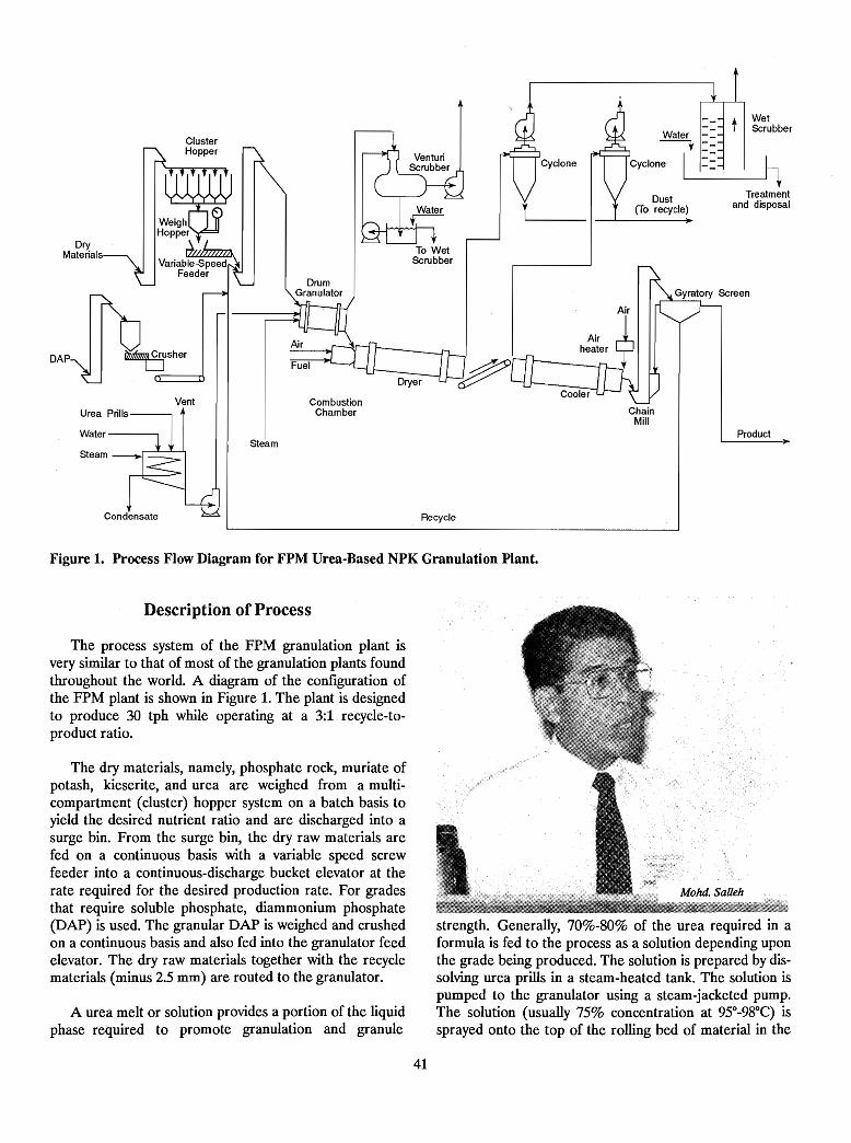
Product
Treatmentand disposal
t WetScrubber
Water -~ -
I_~Dust
(To recycle)
ChainMill
Recycle
To WetScrubber
CombustionChamber
DrumGranulator
Steam
Vent
ClusterHopper
w~H~~~~r~Vartab7.;~
Feeder
Water--------.
Steam
DryMaterials
DAP ~usher
Figure 1. Process Flow Diagram for FPM Urea-Based NPK Granulation Plant.
Description of Process
The process system of the FPM granulation plant isvery similar to that of most of the granulation plants foundthroughout the world. A diagram of the configuration ofthe FPM plant is shown in Figure 1. The plant is designedto produce 30 tph while operating at a 3:1 recycle-toproduct ratio.
The dry materials, namely, phosphate rock, muriate ofpotash, kieserite, and urea are weighed from a multicompartment (cluster) hopper system on a batch basis toyield the desired nutrient ratio and are discharged into asurge bin. From the surge bin, the dry raw materials arefed on a continuous basis with a variable speed screwfeeder into a continuous-discharge bucket elevator at therate required for the desired production rate. For gradesthat require soluble phosphate, diammonium phosphate(DAP) is used. The granular DAP is weighed and crushedon a continuous basis and also fed into the granulator feedelevator. The dry raw materials together with the recyclematerials (minus 2.5 mm) are routed to the granulator.
A urea melt or solution provides a portion of the liquidphase required to promote granulation and granule
strength. Generally, 70%-80% of the urea required in aformula is fed to the process as a solution depending uponthe grade being produced. The solution is prepared by dissolving urea prills in a steam-heated tank. The solution ispumped to the granulator using a steam-jacketed pump.The solution (usually 75% concentration at 95°-98°C) issprayed onto the top of the rolling bed of material in the
41
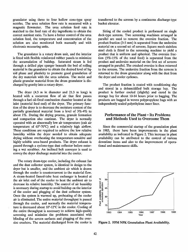
granulator using three to four hollow cone-type spraynozzles. The urea solution flow rate is measured with amagnetic flowmeter. The urea solution feed rate ismatched to the feed rate of dry ingredients to obtain thecorrect nutrient ratio. To have a better control of the ureasolution feed, the temperature and concentration of thesolution are also monitored both manually and withelectronic measuring units.
The granulator is a rotary drum unit, and the interioris fitted with flexible reinforced rubber panels to minimizethe accumulation of buildup. Saturated steam is fedthrough a drilled pipe sparger beneath the bed of rollingmaterial in the granulator to obtain the desired level of liquid phase and plasticity to promote good granulation ofthe dry materials with the urea solution. The moist andplastic granular material from the drum granulator is discharged by gravity into a rotary dryer.
The dryer (4.3 m in diameter and 21.3 m long) isheated with a cocurrent flow of air that first passesthrough a fuel oil-fired combustion chamber located at theinlet (material feed end) of the dryer. The primary function of the dryer is to decrease the moisture content of thepartially granulated material from a level of 3%-4% toabout 1%. During the drying process, granule formationand compaction also continue. The dryer is normallyoperated with an abnormally low air ternperature (exit airtemperature of 65°-70°C) and a relatively high airflow.These conditions are required to achieve the low relativehumidity within the dryer needed to obtain adequatedrying without overheating the temperature-sensitive andhighly soluble urea-based products. The dryer exhaust ispassed through a cyclone-type dust collector before entering a wet scrubber. An inclined belt conveyor is used toconvey the dryer discharge material into the cooler.
transferred to the screens by a continuous discharge-typebucket elevator.
Sizing of the cooled product is performed on singledeck-type screens. Two screening machines arranged inparallel are used to remove the oversize fraction. Theproduct fraction (3-5 mm) is separated from the undersizematerial on a second set of screens. Square mesh stainlesssteel cloth is fitted to the screening machine to yield aproduct that is uniform and spherical. The oversize fraction (5%-15% of the total.feed) is separated from theproduct and undersize material on the frrst set of screensarranged in parallel. The crushed oversize is then returnedto the screens. The undersize fraction from the screens isreturned to the drum granulator along with the dust fromthe dryer and cooler cyclones.
The product fraction is coated with conditioning clayand stored in a dehumidified bulk storage bay. Theproduct is further cooled (slightly) and cured in thestorage bay for about 10-14 hours prior to bagging. Theproducts are bagged in woven polypropylene bags with anindependently sealed polyethylene inner liner.
Performance of the Plant -Its Problemsand Methods Used to Overcome Them
Since the commercial startup of the granulation plantin 1983, there have been improvements in the plantavailability as indicated in Figure 2. This increase in plantavailability can be attributed to the control of variousdowntime items and also to the improvement of operational and maintenance skills.
Figure 2. FPM NPK Granulation Plant Availability.
The rotary drum-type cooler, including the exhaust fanand the dust collector system, is identical in design to thedryer but is smaller, and the ambient air which is drawnthrough the cooler is countercurrent to the material flow.A steam-heated fmned-tube heat exchanger is located atthe air inlet end of the cooler to heat the ambient air todecrease its relative humidity. The control of air humidityis necessary during startup to avoid buildup on the interiorof the cooler and plugging of the dust collector system.Once the system is warmed up, preheating of the coolerair is eliminated. The entire material throughput is passedthrough the cooler, and normally the material temperature is decreased about 10°-12°C in the cooler. Cooling ofthe entire throughput is necessary to achieve high-qualityscreening and minimize the problems associated withblinding of the screen surfaces and plugging of the oversize crushers. The material discharged from the cooler is
42
1983 1984 1985 1986Year
1987 1988 1989
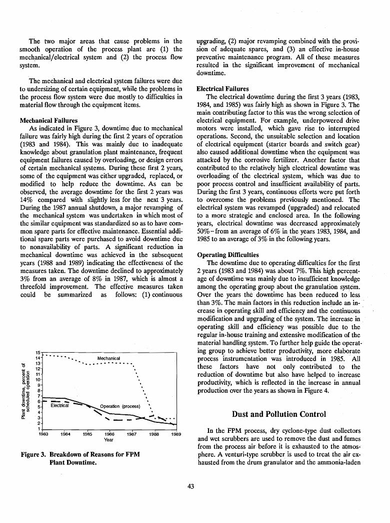
The two major areas that cause problems in thesmooth operation of the process plant are (1) themech.anicaljelectrical system and (2) the process flowsystem.
The mechanical and electrical system failures were dueto undersizing of certain equipment, while the problems inthe process flow system were due mostly to difficulties inmaterial flow through the equipment items.
Mechanical FailuresAs indicated in Figure 3, downtime due to mechanical
failure was fairly high during the fITst 2 years of operation(1983 and 1984). This was mainly due to inadequateknowledge about granulation plant maintenance, frequentequipment failures caused by overloading, or design errorsof certain mechanical systems. During these fITst 2 years,some of the equipment was either upgraded, replaced, ormodified to help reduce the downtime. As can beobserved, the average downtime for the fITst 2 years was14% compared with slightly less for the next 3 years.During the 1987 annual shutdown, a major revamping ofthe mechanical system was undertaken in which most ofthe similar equipment was standardized so as to have common spare parts for effective maintenance. Essential additional spare parts were purchased to avoid downtime dueto nonavailability of parts. A significant reduction inmechanical downtime was achieved in the subsequentyears (1988 and 1989) indicating the effectiveness of themeasures taken. The downtime declined to approximately3% from an average of 8% in 1987, which is almost athreefold improvement. The effective measures takencould be summarized as follows: (1) continuous
1514
........Mechanical
'0 13 ....... -: ..........- 12 .cc
11 .~:B ."'Ill 10~lii
9 .Q. .CliO
:§j 8 .7
.C::l .~~ 6 -- .
5 Electrical -..;;Operation (process) .
c~.
4 ".
~Q.. 3 ..... -2
11983 1984 1985 1986 1987 1988 1989
Year
Figure 3. Breakdown of Reasons for FPMPlant Downtime.
43
upgrading, (2) major revamping combined with the provision of adequate spares, and (3) an effective in-housepreventive maintenance program. All of these measuresresulted in the significant improvement of mechanicaldowntime.
Electrical FailuresThe electrical downtime during the fITst 3 years (1983,
1984, and 1985) was fairly high as shown in Figure 3. Themain contributing factor to this was the wrong selection ofelectrical equipment. For example, underpowered drivemotors were installed, which gave rise to interruptedoperations. Second, the unsuitable selection and locationof electrical equipment (starter boards and switch gear)also caused additional downtime when the equipment wasattacked by the corrosive fertilizer. Another factor thatcontributed to the relatively high electrical downtime wasoverloading of the electrical system, which was due topoor process control and insufficient availability of parts.During the first 3 years, continuous efforts were put forthto overcome the problems previously mentioned. Theelectrical system was revamped (upgraded) and relocatedto a more strategic and enclosed. area. In the followingyears, electrical downtime was decreased approximately50% - from an average of 6% in the years 1983, 1984, and1985 to an average of 3% in the following years.
Operating DifficultiesThe downtime due to operating difficulties for the first
2 years (1983 and 1984) was about 7%. This high percentage of downtime was mainly due to insllfficient knowledgeamong the operating group about the granulation system.Over the years the downtime has been reduced to lessthan 3%. The main factors in this reduction include an increase in operating skill and efficiency and the continuousmodification and upgrading of the system. The increase in ..operating skill and efficiency was possible due to theregular in-house training and extensive modification of thematerial handling system. To further help guide the operating group to achieve better productivity, more elaborateprocess mstrumentation was introduced in 1985. Allthese factors have not only contributed to thereduction of downtime but also have helped to increaseproductivity, which is reflected in the increase in annualproduction over the years as shown in Figure 4.
Dust and Pollution Control
In the FPM process, dry cyclone-type dust collectorsand wet scrubbers are used to remove the dust and fumesfrom the process air before it is exhausted to the atmosphere. A venturi-type scrubber is used to treat the air exhausted from the drum granulator and the ammonia-laden
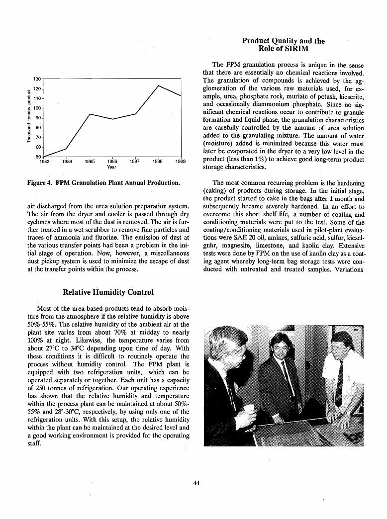
Product Quality and theRole of SIRIM
The FPM granulation process is unique in the sensethat there are essentially no chemical reactions involved.The granulation of compounds is achieved by the agglomeration of the various raw materials used, for example, urea, phosphate rock, muriate of potash, kieserite,and occasionally diammonium" phosphate. Since no significant chemical reactions occur to contribute to granuleformation and liquid phase, the granulation characteristicsare carefully controlled by the amount of urea solutionadded to the granulating mixture. The amount of water(moisture) added is minimized because this water mustlater be evaporated in the dryer to a very low level in theproduct (less than 1%) to achieve good long-term productstorage characteristics.
1989198819871986Year
1985198450...f'll!==-----,--------.-------r-------.--------,-------1
1983
130,...----------------------,
t5 120~
-g 1105.ID 100c.9 90"'C
~ 80~
~ 70
60
Figure 4. FPM Granulation Plant Annual Production.
air discharged from the urea solution preparation system.The air from the dryer and cooler is passed through drycyclones where most of the dust is removed. The air is further treated in a wet scrubber to remove [me particles andtraces of ammonia and fluorine. The emission of dust atthe various transfer points had been a problem in the initial stage of operation. Now, however, a miscellaneousdust pickup system is used to minimize the escape of dustat the transfer points within the process.
The most common recurring problem is the hardening(caking) of products during storage. In the initial stage,the product started to cake in the bags afte'r 1 month andsubsequently became severely hardened. In an effort toovercome this short shelf life, a number of coating andconditioning materials were put to the test. Some of thecoating/conditioning materials used in pilot-plant evaluations were SAE 20 oil, amines, sulfuric acid, sulfur, kieselguhr, magnesite, limestone, and kaolin clay. Extensivetests were done by FPM on the use of kaolin clay as a coating agent whereby long-term bag storage tests were conducted with untreated and treated samples. Variations
Relative Humidity Control
Most of the urea-based products tend to absorb moisture from the atmosphere if the relative humidity is above50%-55%. The relative humidity of the ambient air at theplant site varies from about 70% at midday to nearly100% at night. Likewise, the temperature varies fromabout 27°C to 34°C depending upon time of day. Withthese conditions it is difficult to routinely operate theprocess without humidity control. The FPM plant isequipped with two refrigeration units, which can beoperated separately or together. Each unit has a capacityof 250 tonnes of refrigeration. Our operating experiencehas shown that the relative humidity and temperaturewithin the process plant can be maintained at about 50%55% and 28°-30°C, respectively, by using only one of therefrigeration units..With this setup, the relative humiditywithin the plant can be maintained at the desired level anda good working environment is provided for the operatingstaff.
44
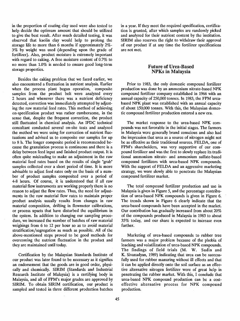
in the proportion of coating clay used were also tested tohelp decide the optimum amount that should be utilizedto give the best result. After much detailed testing, it wasobserved that kaolin clay would help to prolong thestorage life to more than 6 months if approximately 2%3% by weight was used (depending upon the grade offertilizer). Also, product moisture is extremely importantwith regard to caking. A free moisture content of 0.7% tono more than 1.0% is needed to ensure good long-termstorage properties.
Besides the caking problem that we faced earlier, wealso encountered a fluctuation in nutrient analysis. Earlierwhen the process plant began operation, compositesamples from the product belt were analyzed every2 hours and whenever there was a nutrient deficiencydetected, correction was immediately attempted byadjusting the raw material feed rates. This method of achievingon-specification product was rather cumbersome, in thesense that, despite the frequent correction, the productstill fluctuated in chemical analysis. An IFDC technicalconsultant conducted several on-site tests and analyzedthe method we were using for correction of nutrient fluctuations and advised us to composite our samples for upto 8 h. The longer composite period is recommended because the granulation process is continuous and there is adelay between feed input and finished product output. It isoften quite misleading to make an adjustment in the rawmaterial feed rates based on the results of single "grab"samples collected over a short period of time. It is moreadvisable to adjust feed rates only on the basis of a number of product samples composited over a period of4-8 hours. Of course, it is understood that if all rawmaterial flow instruments are working properly there is noreason to adjust the flow rates. Thus, the need for adjustments in the raw material flow rates to maintain properproduct analysis usually results from changes in rawmaterial composition, drifting in flowmeter calibrations,or process upsets that have disturbed the equilibrium i~
the system. In addition to changing our sampling procedure, we increased the number of batches of raw materialweighings from 6 to 12 per hour so as to avoid materialstratification/segregation as much as possible. All of theabove-mentioned steps proved to be good methods forovercoming the nutrient fluctuation in the product andthey are maintained until today.
Certification by the Malaysian Standards Institute ofour product was later found to be necessary as it signifiesan endorsement that the goods are in good order, physically and chemically. SIRIM (Standards anci IndustrialResearch Institute of Malaysia) is a certifying body inMalaysia, and all of FPM's major grades are approved bySIRIM. To obtain SIRIM certification, our product issampled and tested in three different production batches
45
in a year. If they meet the required specification, certification is granted, after which samples are randomly pickedand analyzed for their nutrient content by the institution.SIRIM also reserves the right to withdraw their approvalof our product if at any time the fertilizer specificationsare not met.
Future of Urea-BasedNPKs in Malaysia
Prior to 1983, the only domestic compound fertilizerproduction was done by an ammonium nitrate-based NPKcompound fertilizer company established in 1966 with anannual capacity of 250,000 tonnes. In 1983, the FPM ureabased NPK plant was established with an annual capacityof about 150,000 tonnes. With this, the Malaysian domestic compound fertilizer production entered a new era.
The market response to the urea-based NPK compounds was not favorable in the initial stages. The farmersin Malaysia were generally brand conscious and also hadthe impression that urea as a source of nitrogen might notbe as effective as their traditional sources. FELDA, one ofFPM's shareholders, was very supportive of our compound fertilizer and was the first to slowly replace its traditional ammonium nitrate- and ammonium sulfate-basedcompound fertilizers with urea-based NPK compounds.With the support of FELDA and an aggressive marketingstrategy, we were slowly able to penetrate the Malaysiancompound fertilizer market.
The total compound fertilizer production and use inMalaysia is given in Figure 5, and the percentage contribution of urea-based NPK compounds is given in Figure 6.The trends shown in Figure 6 clearly indicate that theurea-based compounds have been accepted in the market.Our contribution has gradually increased from about 20%of the compounds produced in Malaysia in 1983 to about35% today, and our share is expected to increase evenfurther.
Marketing of urea-based compounds to rubber treefarmers was a major problem because of the phobia ofleaching and volatilization of urea-based NPK compounds.The findings of field trials (M. W. Sudin andK. Sivanadyan, 1989) indicating that urea can be successfully used for rubber manuring without ill effects and thatit can be applied directly onto the soil surface as an effective alternative nitrogen fertilizer were of great help inpenetrating the rubber market. With this, I conclude thaturea-based NPK compound production can be a costeffective alternative process for NPK compoundproduction.
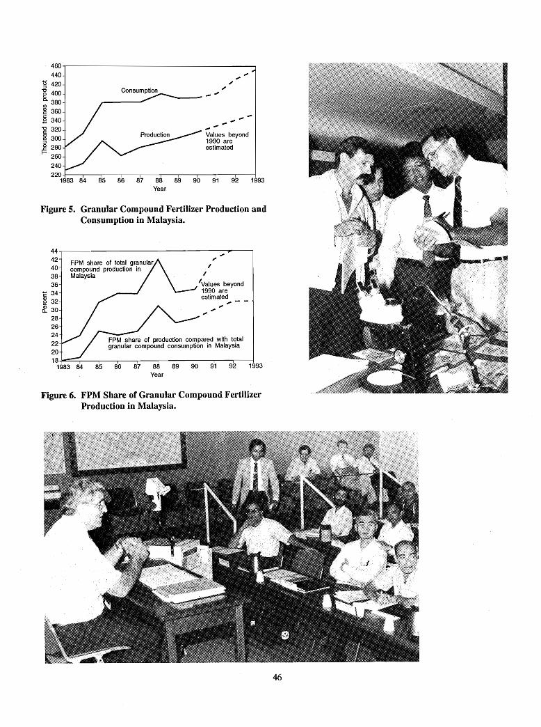
FPM share of production compared with totalgranular compound consumption in Malaysia
Figure 6. FPM Share of Granular Compound FertilizerProduction in Malaysia.
.",-
Values beyond1990 areestimated
,.,,'Values beyond1990 areestimated
~--,~
~
----- --"Consumption
FPM share of total granularcompound production inMalaysia
44.,..--------------------""....------,42403836
c 34§ 32~ 30-
282624222018...-=~...,...._-____r_-___,..--.,.._-___r_-.....,....-____r--.,.._-....__-___i
1983 84 85 86 87 88 89 90 91 92 1993Year
460~-----------------------.,
440
g 420
e 4000. 380I/)
~ 360c.9 340-g 320
~ 300
~ 280260
240220 +--....__--,-------r--,---------,-----,------.-------,--"T"""--~
1983 84 85 86 87 88 89 90 91 92 1993Year
Figure 5. Granular Compound Fertilizer Production andConsumption in Malaysia.
46
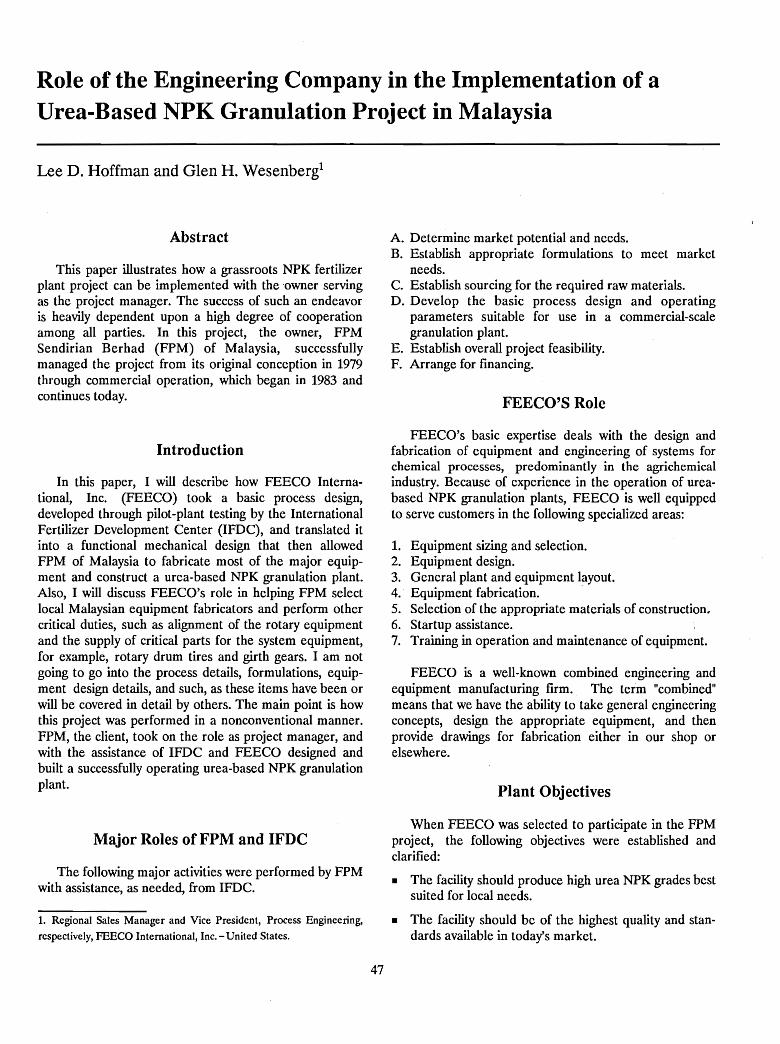
Role of the Engineering Company in the Implementation of aUrea-Based NPK Granulation Project in Malaysia
Lee D. Hoffman and Glen H. Wesenberg!
Abstract
This paper illustrates how a grassroots NPK fertilizerplant project can be implemented with the owner servingas the project manager. The success of such an endeavoris heavily dependent upon a high degree of cooperationamong all parties. In this project, the owner, FPMSendirian Berhad (FPM) of Malaysia, successfullymanaged the project from its original conception in 1979through commercial operation, which began in 1983 andcontinues today.
Introduction
In this paper, I will describe how FEECO International, Inc. (FEECO) took a basic process design,developed through pilot-plant testing by the InternationalFertilizer Development Center (IFDC), and translated itinto a functional mechanical design that then allowedFPM of Malaysia to fabricate most of the major equipment and construct a urea-based NPK granulation plant.Also, I will discuss FEECO's role in helping FPM selectlocal Malaysian equipment fabricators and perform othercritical duties, such as alignment of the rotary equipmentand the supply of critical parts for the system equipment,for example, rotary drum tires and girth gears. I am notgoing to go into the process details, formulations, equipment design details, and such, as these items have been orwill be covered in detail by others. The main point is howthis project was performed in a nonconventional manner.FPM, the client, took on the role as project manager, andwith the assistance of IFDC and FEECO designed andbuilt a successfully operating urea-based NPK granulationplant.
Major Roles of FPM and IFDC
The following major activities were performed by FPMwith assistance, as needed, from IFDC.
1. Regional Sales Manager and Vice President, Process Engineering,
respectively, FEECO International, Inc. - United States.
47
A. Determine market potential and needs.B. Establish appropriate formulations to meet market
needs.C. Establish sourcing for the required raw materials.D. Develop the basic process design and operating
parameters suitable for use in a commercial-scalegranulation plant.
E. Establish overall project feasibility.F. Arrange for financing.
FEECO'S Role
FEECO's basic expertise deals with the design andfabrication of equipment and engineering of systems forchemical processes, predominantly in the agrichemicalindustry. Because of experience in the operation of ureabased NPK granulation plants, FEECO is well equippedto serve customers in the following specialized areas:
1. Equipment sizing and selection.2. Equipment design.3. General plant and equipment layout.4. Equipment fabrication. .5. Selection of the appropriate materials of construction.6. Startup assistance.7. Training in operation and maintenance of equipment.
FEECO is a well-known combined engineering andequipment manufacturing firm. The term "combined"means that we have the ability to take general engineeringconcepts, design the appropriate equipment, and thenprovide drawings for fabrication either in our shop orelsewhere.
Plant Objectives
When FEECO was selected to participate in the FPMproject, the following objectives were established andclarified:
• The facility should produce high urea NPK grades bestsuited for local needs.
• The facility should be of the highest quality and standards available in today's market.
• The cost to obtain the above facilities should be keptto a minimum.
• The facility should contain as much local (Malaysian)content as possible.
With these objectives in mind, I will explain how FEECOassisted FPM with both the engineering and manufacturing of the equipment system.
First Objective - The Facility Should ProduceHigh-Urea NPK Grades Best Suited for Local Needs
To design an equipment system to meet this objective,FEECO had to know some basic information, such as successful formulations (IFDC determined these from pilotplant work), type and quality of raw materials to be used,and the rates of production required.
Formulations had to be known or determined for eachNPK grade of fertilizer to be produced. Together IFDC,FPM, and FEECO reviewed each formulation before arriving at a set of grades that could be manufactured in theproposed granulation facility. In summary, the followingdata were obtained from the above review:
• A list of grades to be manufactured.
• A list of the raw materials and quantities to be used inproduction of the above grades.
• Projections of the quantities of each grade requiredper year.
• A report indicating the expected optimum productionrates for each of the major grades.
48
Second Objective - The Facility Should be of the HighestQuality and Standards Available in Today's Market
From the information developed in the first objective,along with IFDC's assistance, we were able to do detailedplant design. To accomplish this we first worked throughthe following four steps:
• We prepared a flow diagram tabulating data for eachof the major grades to be produced. The flow diagramconsisted of the following five main systems:
1. Batch weigh and feed system:a. Clod breaker.b. Raw material elevator.c. Single-deck screen.d. Oversize chain mill.e. Cluster hopper.f. Weigh hopper.g. Gravity blend and surge hopper.h. Continuous feed conveyer.
2. Granulation loop:a. Recycle surge hopper.b. Recycle elevator.c. Fluid feed systems.d. Urea solution or melt tank.e. Scrubber and accessories.f. Rotary drum granulator.
3. Drying/cooling loop:a. Fuel system.b. Burner and controls.c. Combustion chamber.d. Rotary dryer.e. Air pollution equipment and exhaust fans.f. Transfer conveyor.g. Rotary cooler.
4. Sizing loop:a. Screen feed elevator.b. Single-deck oversize screens.c. Single-deck product screens.d. Oversize crushers.e. Product elevator.
5. Product coating loop:a. Surge hopper.b. Coating agent feed system.c. Coating drum.
• We then calculated and selected the proper equipmentsizes to match the flow diagrams and production ratesestablished.
• Next, we prepared a full description (specification) ofeach piece of equipment selected.
• We then prepared general layout drawings for thegranulation plant.
Third Objective - The Cost of the Facilities Should beKept to a Minimum
rhe majority of costs saved were in the following twomajor areas:
1. By acting as project manager, FPM was able to avoidmajor administrative costs often associated with largeengineering ftrms.
2. The detailed information supplied by FEECO affordedthe project team the flexibility to have much of thefabrication and construction done by local (Malaysian)companies. The following are some of the major advantages that accrued as a result of maximizing localconstruction content of a facility:a. Import duties were minimized.b. In the majority of cases, local labor rates were
much more attractive.c. Freight savings were maximized.d.' Additional jobs were created in the local market.e. Technology was transferred to the local
marketplace during the fabrication and construction phases of the project. This technology stayslong after the project is completed, thus assisting inthe development of the local economy and technical resource base.
The following information is normally supplied byFEECO to facilitate local construction:
1. Detailed specifications and drawings for each piece ofequipment.
2. Detailed system layout drawings.3. Shop fabrication drawings on all equipment to be fur
nished, including:a. Rotary dryer.b. Rotary cooler.c. Rotary granulator.d. Product conditioning system.e. Chutes.f. Hoppers.g. Transitions.h. Guards.1. Ducting.J. Hoods.k. Conveyers and bucket elevators.1. Metering and control equipment.m. Electrical switchgear.n. Air handling and emission control equipment.o. Other ancillary equipment required for a complete
system.4. Determination of the most appropriate source for each
equipment item.5. Selection of the most appropriate vendors to be sent
bid requests. Examples of purchased items include:
49
a. Trunnion wheels.b. Thrust rollers.c. Drives.d. Large bearings.e. Screens.f. Other specialized equipment that would not be
available locally.6. Preparation of inquiries to be sent to the appropriate
vendors and evaluation of bids and recommendationsas to which supplier should be issued purchase orders.This may include the issue of purchase orders, ifappropriate.
7. Inspection and expediting of items purchased forfabrication and erection.
Fourth Objective-The Facility Should Contain as MuchLocal Content as Possible
In addition to maximizing local fabrication of processequipment, the design/construction information providedby FEECO made it possible to perform essentially all siteconstruction using local construction firms and labor. Tofacilitate construction, FEECO provided the following:
1. Specifications to be used for construction. of the plantincluding:a. Concrete foundations.b. Support steel.c. Electrical wiring.d. Plumbing.e. Siding and roofing.f. Equipment erection.g. Miscellaneous civil works.
2. Drawings for construction of above items.3. Inquiries (invitation to bid) to be sent to coristruction
bidders.4. Evaluation of local fabricators' facilities and abilities,
including recommendations for award of contracts.5. Supervision of construction and installation of critical
equipment items as requested (for example, the rotarydrums).
6. Consultation on startup relative to the equipment andprocess as requested.
Conclusion
As a result of the above described method of implementation, the FPM factory was constructed in a veryeconomic way and the local economy benefited by providing the majority of equipment fabrication and constructionservices. An added benefit of the methodology used wasthat the technical skills of the Malaysian fabrication industry were expanded to include large-scale fertilizer plantequipment fabrication and construction.
Production of Urea-Based Fertilizers With Pipe-CrossReactor Technology - TVA Experience
B. R~'Parker, M. M. Norton, and B. W. Curtis1
Abstract
The technical aspects of applying Tennessee ValleyAuthority (TVA) pipe-cross reactor technology to theproduction of granular fertilizers containing significantamounts of urea are discussed. Detailed pilot-plant dataare given on the production of a variety of grades usingvarious formulations, equipment configurations, andoperating conditions. The results demonstrate thefeasibilit)' of using pipe-cross reactor technology for theproduction of urea-based NPK formulations. Although thepreneutralizer and its associated problems are eliminated,use of the pipe-cross reactor presents a very specific needfor close process control, particularly in regard to thechoice of raw materials and control of process temperaturesto avoid excessive corrosion. These parameters arediscussed in detail.
Introduction
For more than 25 years, the Tennessee ValleyAuthority (TVA) has conducted research and development programs to demonstrate the use of urea as a sourceof supplemental nitrogen for the production of granularfertilizers. Urea often causes granulation and dryingproblems, and the hygroscopic products may require special handling. However, interest in using urea continuesbecause it has a high analysis, which can result in savingsin shipping and production costs, and it does not havesome of the attendant hazards of ammonium nitrate.
In 1964, a process for production of granular ureaammonium phosphate fertilizer based on diammoniumphosphate (DAP) with the addition. of urea as supplemental nitrogen was demonstrated (1). When solid urea wasused, it was metered into the recycle stream in a typicalDAP-type plant, and when urea solution was used, it wasadded directly to the granulator. This slurry process hasbeen used successfully in large commercial operations in
1. Chemical Engineer, Senior Scientist, and Research Chemist, respec
tively, Tennessee Valley Authority (IVA)- United States.
50
India and other parts of the world to produce such ureabased grades as 28-28-0, 14-35-14, 15-15-15, 14-28-14, and19-19-19 (2,:2,1).
Other similar processes using nongranular monoammonium phosphate (MAP) as the basic source of phosphate and urea as supplemental nitrogen have beensuccessful in commercial operations. Often these requiresmall amounts of either phosphoric or sulfuric acid andammonia to enhance granulation. This process has beenused in Spain, Turkey, and the United Kingdom (~,n).
Urea has been used in combination with either singleor triple superphosphate to produce granular NP or NPKfertilizers (1,8), and this process has been popular in theUnited Kingdom for production of a 20-10-10 grade.
However, the presence of urea in the above granularproducts makes drying difficult, because high temperatures cannot be used wjthout melting the product. Becauseof the drying problems associated with urea-basedproducts, more recent research and developmentprograms have concentrated on the production of ureabased products with melt-granulation processes. In theseprocesses, all or a part of the fertilizer ingredients are fedto the granulator in the form of melts or low-moistureslurries, and because of the low moisture content, little orno drying is required.
Previous Melt-Granulation ProcessesPipe-reactor processes, in which ammonium phosphate
melts were formed by the reaction of ammonia and phosphoric acid in a standard pipe tee and pipe reaction tubeand then distributed to a granulator, were shown to beadaptable to the production of urea-based products. Oneprocess, which used a spray reactor, pipe reactor, vapordisengager, and pug mill, was used in TVA'sdemonstration-scale melt-granulation plant for more than10 years to produce 28-28-0 and 35-17-0 grades of ureaammonium phosphate products at production rates up to450 and 340 stpd (409 and 309 tpd), respectively (2,10).Good-quality products containing 20% to 35% of theirphosphate as polyphosphates were made, but the process
was not commercially accepted because of the non-typicalequipment.
Another melt-granulation process was shown on pilotscale to the fertilizer industry in 1974, in which an ammonium phosphate melt was produced in a tankpreneutralizer followed by a pipe reactor and then fed to adrum granulator. Urea and other solid feed materialswere added to the recycle stream, so that typical grades,such as 19-19-19, 12-24-24, and 15-30-15, could beproduced (11,12). It was initially thought that thepreneutralization step decreased the formation of scalebuildup in the pipe reactor, but later testing showed thatthe preneutralizer could be omitted and subsequentlyresulted in the development and use of the pipe-crossreactor.
Melt-Granulation Process Using aPipe-Cross Reactor
The pipe-cross reactor was developed in a unique wayin that its incorporation into a commercial-scale fertilizergranulation plant was followed by pilot-plant studies tofurther define the desired operating parameters andgrades that could be made. The pipe-cross reactor wasdeveloped in an effort to solve an environmental problemencountered while incorporating sodium nitrate into agranular fertilizer. The byproduct sodium nitrate was inthe form of fine, moist crystals not suitable for direct application to the soil. In early tests of incorporating the crystals into a granular fertilizer, the reaction of the sodiumnitrate, sulfuric acid, and ammonia as they were fed to thegranulator resulted in flames and emission of largevolumes of brownish-white fumes from the granulator.The addition of phosphoric acid did not suppress theflames and fuming, so a pipe-cross reactor was installed inplace of the preneutralizer.
The initial commercial-scale pipe-cross reactor used astandard 3-inch-diameter pipe as the reaction tube andwas similar to previous pipe reactors used except for onesignificant aspect - the feed end was designed in the configuration of a standard pipe cross rather than a pipe teeas with the prior pipe reactors. In Figure 1, where onetypical reactor used in pilot-plant testing is shown, a standard pipe-cross fitting is used. This pipe-cross configuration allowed the separate but simultaneous introduction ofsulfuric acid and the subsequent neutralization reaction ofthe phosphoric and sulfuric acids with ammonia. Enoughammonia, either gas or liquid, was added to neutralize thesulfuric acid and to produce the desired melt NH3:H3P04mole ratio. The melt was discharged by pressuredeveloped within the reaction tube onto the rolling bed ofsolids in a drum granulator.
51
Advantages of the Pipe-Cross ReactorSubsequent operation of the pipe-cross reactor, both in
commercial and pilot-scale operation, showed severaladvantages over the use of a preneutralizer in a conventional drum granulation plant. The early operationproduced NP or NPK grades without the addition of urea,but subsequent operation with urea addition showedsimilar or, in some cases, slightly less advantage. Theseadvantages include the following:
1. Larger amounts of acids, both phosphoric and sulfuric,can be used in the formulations.
2. Drying of the product is often not required, and dryingcosts are lower. .
3. There is less formation of troublesome, difficult-toscrub ammonium chloride fumes in the granulator exhaust gases when sulfuric acid and potassium chlorideare included in a formulation.
4. Investment costs are lower and operation of the plantis easier because the preneutralizer and its associatedpumps, piping, and meters are not required.
5. Pollution control is less complex and less expensive because the preneutralizer and its scrubbers areeliminated.
6. Moisture content of the pipe-cross reactor slurry ormelt is lower than that of a preneutralizer slurry, asthere is a more favorable water balance in the process.
7. Granular MAP can be conveniently produced and canbe used to blend a wider range of grades than canDAP.
Pipe-Cross Reactor Design andOperating Criteria
The temptation to make the design and operation of apipe-cross reactor too complicated should be avoided.Although there is a range of design criteria for sizing apipe-cross reactor and there will be slight variationsdepending upon the grade(s) to be produced, the following are guidelines to follow when orthophosphate-basedfertilizers are to be produced:
1. The optimum heat flux per unit of pipe-cross section,based on the chemical reaction occurring in the reactor, is 600 x 103 Btu/h· in2 (23.4 x 10³ kcal/h. cm2
).
2. The ammonia sparger should be installed in the longitudinal centerline of the pipe and extend at leastone pipe diameter past the end of the cross.
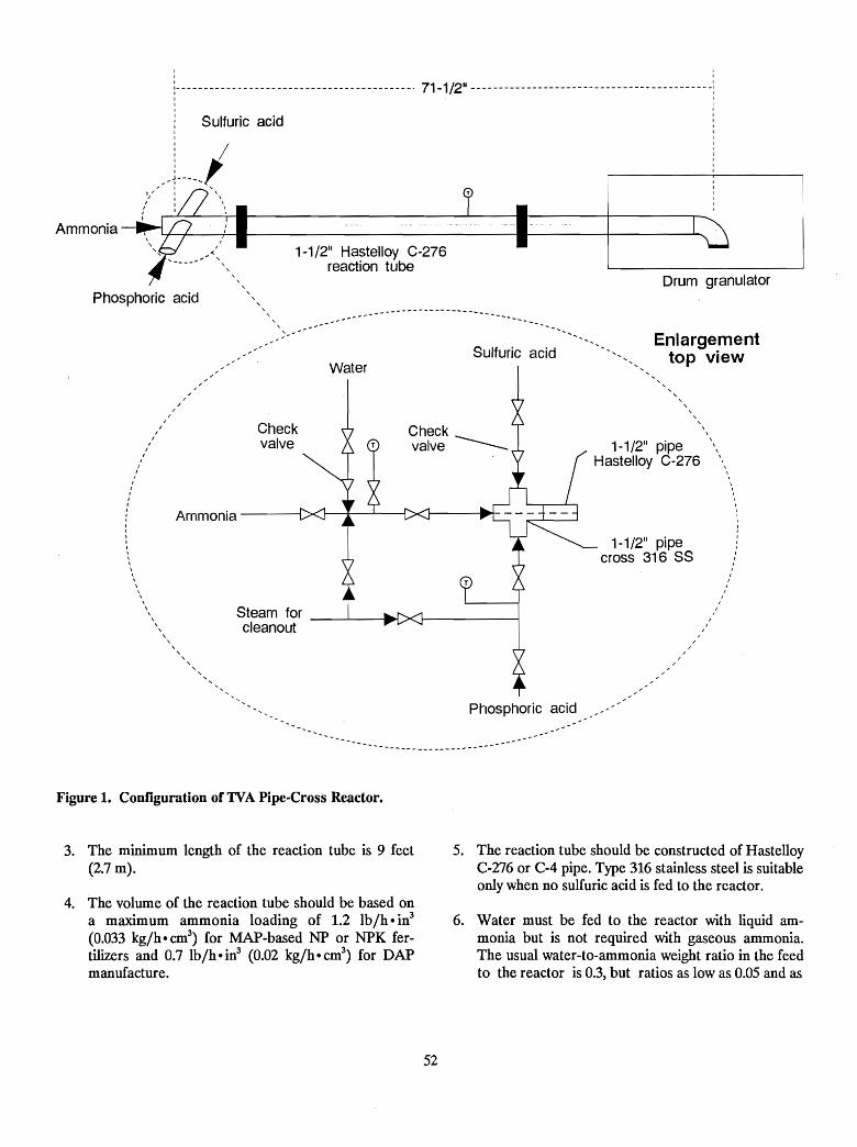
-----------------------------------------. 71-1/2 11 - - - - - - - - - - - - - - - - - - - - - - - - - - - - - - - - - - - - - - - - --
Sulfuric acid
IIIIII
I
II
II
I
I
II
I
1-1/21\ pipecross 316 SS
Drum granulator
Enlargementtop view
, , ,, ,,,\
1-1/211 pipe '\Hastelloy C-276 \ \
\
\\,,
Sulfuric acid
1-1/211 Hastelloy C-276reaction tube
Checkvalve
Steam for _----'_-II~cleanout
I-:
~~ , , , , , ,, , , ,, , ,:; .........
Water,
,/
II
II
II
II
II
II
II
IIII
i Ammonia --------lII,III,\\\\\\\
\
\\
\ ,,,,,, , ,
Phosphoric acid
Ammonia
Phosphoric acid
---
Figure 1. Configuration of 1VA Pipe-Cross Reactor.
3. The minimum length of the reaction tube is 9 feet(2.7 m).
4. The volume of the reaction tube should be based ona maximurn ammonia loading of 1.2 lbjh e in3
(0.033 kgjh e cm3) for MAP-based NP or NPK fer
tilizers and 0.7 Ibjh e in3 (0.02 kgjh e cm3) for DAP
manufacture.
5. The reaction tube should be constructed of HastelloyC-276 or C-4 pipe. Type 316 stainless steel is suitableonly when no sulfuric acid is fed to the reactor.
6. Water must be fed to the reactor with liquid ammonia but is not required with gaseous ammonia.The usual water-to-ammonia weight ratio in the feedto the reactor is 0.3, but ratios as low as 0.05 and as
52
high as 1.0 have been used successfully. Although notrequired, a small amount of water fed with gaseousammonia will result in smoother operation and moreuniform reaction. The reactor temperature can becontrolled by the water addition to the ammonia orby addition of a separate stream of water or scrubberliquor to the reactor.
7. The reactor temperature (skin temperature is usuallymost easily measured) should be maintained between270° and 3OO0P (132°-149°C) for best reactor operation for MAP-based grades. At temperatures above4OO0 P (204°C), polyphosphates are produced, butpotential for buildup within the reactor exists. Therange between 300° and 4OO0P (149°-204°C) shouldbe avoided if possible because of greater tendency ofincreased buildup. Corrosion is more severe above4000 P (204°C) when sulfuric acid is used, and thematerial of construction recommended earlier maynot give acceptable reactor life.
8. The reaction tube should be sloped upward towardthe granulator for more complete reaction and lowerammonia evolution.
9. Melt or slurry from the reactor should dischargeonto the center of the granulator bed at a longitudinal distance of one-third to one-half the distance from the feed end. The discharge should be atleast 2 feet (61 em) above the bed.
10. A minimum of 100 pounds (45 kg) of phosphoricacid per short ton of product should be included inthe formulation to minimize corrosion of the reaction tube. It is desirable that the ratio of phosphoricacid to sulfuric acid be maintained at 1:1 or greaterbecause corrosion increases as this ratio decreases.
11. All the sulfuric acid in the formulation should be fedto the pipe-cross reactor to minimize formation ofammonium chloride particulate in the granulatorwhen producing NPK grades with potassiumcWoride.
12. The formulation should be calculated to give a pipecross reactor melt NH3:H3P04 mole ratio of 1.0 forMAP-based products. Smoother, rounder productand lower ammonia evolution can be obtained if aportion of the phosphoric acid is fed to thegranulator or if the pipe-cross reactor melt moleratio is maintained between 0.6 and 0.8 and additional ammonia is added to the bed.
53
Pilot-Plant Production of Urea-Based FertilizersBy the early 1980s there were more than 30 commer
cial plants in the United States that had a pipe-crossreactor installed or planned (13). Initial production offertilizers in these plants included many grades ofammonium phosphate sulfate fertilizers, and althoughurea-based grades were successfully made in several commercial plants, this paper focuses on urea-based gradesmade during an extended pilot-plant test program atTVA. This allows better comparisons of a wide range ofproducts. The commercial plants operated with an orthophosphate system where pipe-cross reactor melt temperatures below 300°F (149°C) produced ammoniumorthophosphates. Some of the pilot-plant testing usedhigher temperatures so that some of the orthophosphateswere converted to polyphosphates. In many cases,products with polyphosphate contents can be used as intermediates to produce superior fluid fertilizers, but ingeneral the polyphosphates do not result in superioragronomic or storage properties for the granular fertilizers. In addition, the higher reactor temperatures resultin an increased tendency for buildup in the pipe and, whensulfuric acid is also fed to the reactor, increased corrosion.The data on pilot-plant operation should be taken not asrecommendations to produce these grades but as exampIes and comparisons of options.
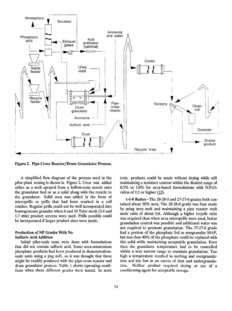
Oversize
l--__~ Onsizeproduct
L Cooler
OdJ--I
I /l/
Screens ~
V~c~~:n
D
Ammoniaand water
Acidpreheater(optional)
---, Exhausti gasesI
Scrubber
Urea
I melt JJ~ If]~ID?, IpI-U ~:, Ipe·
: Drum _~' I crossI granulator i reactor
I Ammonia I
I Sulfuric acid i ;/\' /
L~crb//
gSOlid~feed~~ \
Atmosphere,
Recycle fines _~~-----------------------------
Figure 2. Pipe-Cross Reactor/Drum Granulator Process.
A simplified flow diagram of the process used in thepilot-plant testing is shown in Figure 2. Urea was addedeither as a melt sprayed from a hollow-cone nozzle ontothe granulator bed or as a solid along with the recycle tothe granulator. Solid urea was added in the form ofmicroprills or prills that had been crushed in a rollcrusher. Regular prills could not be well incorporated intohomogeneous granules when 6 and 10 Tyler mesh (3.4 and1.7 mm) product screens were used. Prills possibly couldbe incorporated if larger product sizes were made.
I
Production ofNP Grades With NoSulfuric Acid Addition
Initial pilot-scale tests were done with formulationsthat did not contain sulfuric acid. Some urea-ammoniumphosphate products had been produced in demonstrationscale units using a pug milJ, so it was thought that thesemight be readily produced with the pipe-cross reactor anddrum granulator process. Table 1 shows operating conditions when three different grades were tested. In most
tests, products could be made without drying while stillmaintaining a moisture content within the desired range of0.5% to 1.0% for urea-based formulations with N:P20Sratios of 1:1 or higher (12).
1-1-0 Ratios - The 28-28-0 and 27-27-0 grades both contained about 50% urea. The 28-28-0 grade was best madeby using urea melt and maintaining a pipe reactor meltmole ratio of about 0.6. Although a higher recycle ratiowas required than when urea microprills were used, bettergranulation control was possible and additional water wasnot required to promote granulation. The 27-27-0 gradehad a portion of the phosphate fed as nongranular MAP,but less than 40% of the phosphate could be replaced withthis solid while maintaining acceptable granulation. Eventhen the granulator temperature had to be controlledwithin a very narrow range to maintain granulation. Toohigh a temperature resulted in melting and overgranulation and too low in an excess of dust and undergranulation. Neither product required drying or use of aconditioning agent for acceptable storage.
54
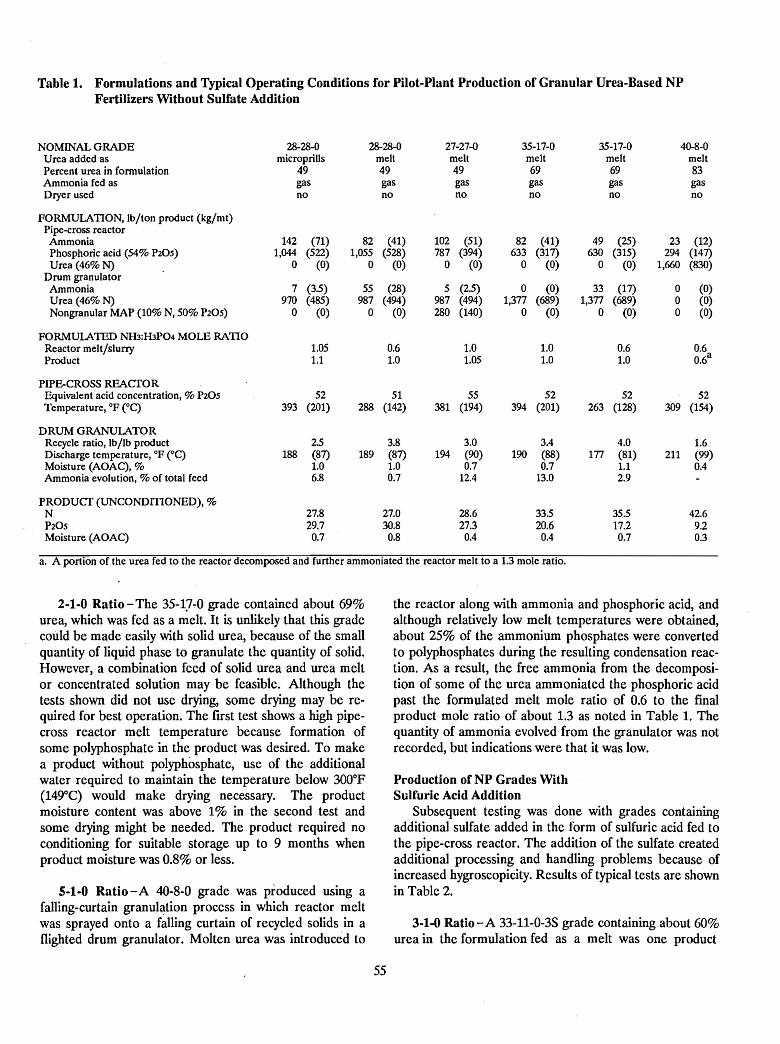
Table 1. Formulations and Typical Operating Conditions for Pilot-Plant Production of Granular Urea-Based NPFertilizers Without Sulfate Addition
NOMINAL GRADE 28-28-0 28-28-0 27-27-0 35-17-0 35-17-0 40-8-0Urea added as microprills melt melt melt melt meltPercent urea in formulation 49 49 49 69 69 83Ammonia fed as gas gas gas gas gas gasDryer used no no no no no no
FORMUlATION, lb/ton product (kg/mt)Pipe-cross reactorAmmonia 142 (71) 82 (41) 102 (51) 82 (41) 49 (25) 23 (12)Phosphoric acid (54% P20S) 1,044 (522) 1,055 (528) 787 (394) 633 (317) 630 (315) 294 (147)Urea (46%N) 0 (0) 0 (0) 0 (0) 0 (0) 0 (0) 1,660 (830)
Drum granulatorAmmonia 7 (3.5) 55 (28) 5 (2.5) 0 (0) 33 (17) 0 (0)Urea (46%N) 970 (485) 987 (494) 987 (494) 1,377 (689) 1,377 (689) 0 (0)Nongranular MAP (10% N, 50% P20S) 0 (0) 0 (0) 280 (140) 0 (0) 0 (0) 0 (0)
FORMUlATED NH3:H3P04 MOLE RATIOReactor melt/slurry 1.05 0.6 1.0 1.0 0.6 0.6Product 1.1 1.0 1.05 1.0 1.0 0.6
a
PIPE-CROSS REACTOREquivalent acid concentration, %P20S 52 51 55 52 52 52Temperature, OF eC) 393 (201) 288 (142) 381 (194) 394 (201) 263 (128) 309 (154)
DRUM GRANUlATORRecycle ratio, lb/lb product 2.5 3.8 3.0 3.4 4.0 1.6Discharge temperature, OF eC) 188 (87) 189 (87) 194 (90) 190 (88) 177 (81) 211 (99)Moisture (AOAC), % 1.0 1.0 0.7 0.7 1.1 0.4Ammonia evolution, % of total feed 6.8 0.7 12.4 13.0 2.9
PRODUCT (UNCONDmONED), %N 27.8 27.0 28.6 33.5 35.5 42.6P20S 29.7 30.8 27.3 20.6 17.2 9.2Moisture (AOAC) 0.7 0.8 0.4 0.4 0.7 0.3
a. A portion of the urea fed to the reactor decomposed and further ammoniated the reactor melt to a 1.3 mole ratio.
2-1-0 Ratio-The 35-17.,.0 grade contained about 69%urea, which was fed as a melt. It is unlikely that this gradecould be made easily with solid urea, because of the smallquantity of liquid phase to granulate the quantity of solid.However, a combination feed of solid urea and urea meltor concentrated solution may be feasible. Although thetests shown did not use drying, some drying may be required for best operation. The ftrst test shows a high pipecross reactor melt temperature because formation ofsome polyphosphate in the product was desired. To makea product without polyphosphate, use of the additionalwater required to maintain the temperature below 300°F(149°C) would make drying necessary. The productmoisture content was above 1% in the second test andsome drying might be needed. The product required noconditioning for suitable storage up to 9 months whenproduct moisture was 0.8% or less.
5-1-0 Ratio-A 40-8-0 grade was produced using afalling-curtain granulation process in which reactor meltwas sprayed onto a falling curtain of recycled solids in aflighted drum granulator. Molten urea was introduced to
55
the reactor along with ammonia and phosphoric acid, andalthough relatively low melt temperatures were obtained,about 25% of the ammonium phosphates were convertedto polyphosphates during the resulting condensation reaction. As a result, the free ammonia from the decomposition of some of the urea ammoniated the phosphoric acidpast the formulated melt mole ratio of 0.6 to. the ftnalproduct mole ratio of about 1.3 as noted in Table 1. Thequantity of ammonia evolved from the granulator was notrecorded, but indications were that it was low.
Production of NP Grades WithSulfuric Acid Addition
Subsequent testing was done with grades containingadditional sulfate added in the form of sulfuric acid fed tothe pipe-cross reactor. The addition of the sulfate createdadditional processing and handling problems because ofincreased hygroscopicity. Results of typical tests are shownin Table 2.
3-1-0 Ratio-A 33-11-0-3S grade containing about 60%urea in the formulation fed as a melt was one product
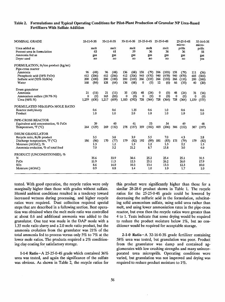
Table 2. Formulations and Typical Operating Conditions for Pilot-Plant Production of Granular NP Urea-BasedFertilizers With Sulfate Addition
NOMINAL GRADE 33-11-O-3S 33-11-O-5S 33-11-0-3S 25-25-0-4S 25-25-O-4S 25-25-0-4S 32-16-0-3Smicro- micro-
U rea added as melt melt melt melt melt priUs priUsPercent urea in formulation 63 61 59 36 36 36 58Ammonia fed as gas gas gas gas gas gas gasDryer used no no no no no no yes
FORMULATION, lb/ton product (kg/mt)Pipe-cross reactor
Ammonia 96 (48) 96 (48) 136 (68) 158 (79) 206 (103) 158 (79) 111 (56)Phosphoric acid (54% P20S) 412 (206) 412 (206) 412 (206) 940 (470) 940 (470) 940 (470) 605 (303)Sulfuric acid (92% H2SO4) 200 (100) 200 (100) 200 (100) 266 (133) 266 (133) 266 (133) 200 (100)Water 168 (84) 128 (64) 136 (68) 0 (0) 12 (6) 66 (33) 40 (20)
Drum granulatorAmmonia 21 (11) 21 (11) 35 (18) 48 (24) 0 (0) 48 (24) 31 (16)Ammonium sulfate (20.7% N) 0 (0) 165 (83) 0 (0) 0 (0) 0 (0) 0 (0) 0 (0)Urea (46% N) 1,259 (630) 1,217 (609) 1,183 (592) 728 (364) 728 (364) 728 (364) 1,150 (575)
FORMULATED NH3:H3P04 MOLE RATIOReactor melt/slurry 0.6 0.6 1.35 0.6 1.0 0.6 0.6Product 1.0 1.0 2.0 1.0 1.0 1.0 1.0
PIPE-CROSS REACTOREquivalent acid concentration, % P20S 39 40 41 53 54 49 48Temperature, OF eC) 264 (129) 269 (132) 278 (137) 359 (182) 403 (206) 306 (152) 387 (197)
DRUM GRANULATORRecycle ratio, lb/lb product 3.5 3.8 3.9 5.5 7.0 4.3 2.8Discharge temperature, OF eC) 186 (86) 170 (77) 179 (82) 192 (89) 181 (83) 175 (79) 179 (82)Moisture (AOAC), % 1.3 1.2 1.3 1.2 1.3 2.2 1.3Ammonia evolution, % of total feed 7.0 5.2 21.2 8.7 15.8 3.0 4.0
PRODUCT (UNCONDmONED), %N 35.6 33.9 34.6 25.2 25.4 25.1 31.5P20S 11.9 11.5 12.3 25.1 26.2 26.0 17.9S03 8.6 14.0 10.3 13.4 13.3 12.3 10.0Moisture (AOAC) 0.9 0.8 1.4 1.0 1.0 1.7 1.0
tested. With good operation, the recycle ratios were onlymarginally higher than those with grades without sulfate.Humid ambient conditions resulted in a tendency towardincreased wetness during processing, and higher recycleratios were required. Dust collection required specialsteps that are described in a following section. Best operation was obtained when the melt mole ratio was controlledat about 0.6 and additional ammonia was added to thegranulator. One test was made in the DAP mode with a1.35 mole ratio slurry and a 2.0 mole ratio product, but theammonia evolution from the granulator was 21% of thetotal ammonia fed to process versus only 5% to 7% at thelower mole ratios. The products required a 2% conditioning clay coating for. satisfactory storage.
1-1.() Ratio-A 25-25-0-4S grade which contained 36%urea was tested, and again the significance of the sulfatewas obvious. As shown in Table 2, the recycle ratios for
56
this product were significantly higher than those for asimilar 28-28-0 product shown in Table 1. The recycleratios for the 25-25-0-4S grade could be lowered bydecreasing the sulfuric acid in the formulation, substituting solid ammonium sulfate, using solid urea rather thanmelt, and using lower ammoniation rates in the pipe-crossreactor, but even then the recycle ratios were greater than4 to 1. Tests indicate that some drying would be requiredto reduce the product moisture below 1%, but no conditioner would be required for acceptable storage.
2-1-0 Ratio - A 32-16-0-3S grade fertilizer containing58% urea was tested, but granulation was poor. Productfrom the granulator was damp and contained agglomerates with low crushing strengths and many unincorporated urea microprills. Operating conditions werevaried, but granulation was not improved and drying wasrequired to reduce product moisture to 1%.
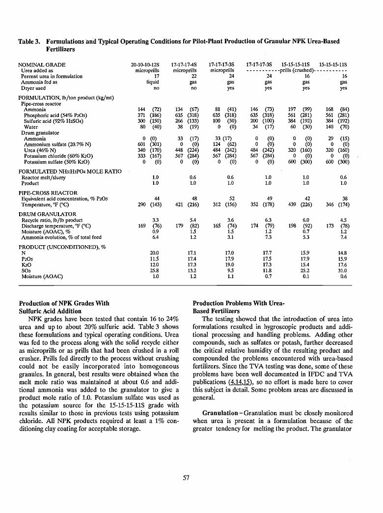
Table 3. Formulations and Typical Operating Conditions for Pilot-Plant Production of Granular NPK Urea-BasedFertilizers
NOMINAL GRADE 20-10-10-125 17-17-17-45 17-17-17-35 17-17-17-35 15-15-15-115 15-15-15-115Urea added as micropriUs micropriUs micropriUs - - - - - - - - - - -priUs (crushed)- - - - - - - - - - -Percent urea in formulation 17 22 24 24 16 16Ammonia fed as liquid gas gas gas gas gasDryer used no no yes yes yes yes
FORMUlATION, lb/ton product (kg/mt)Pipe-eross reactorAmmonia 144 (72) 134 (67) 81 (41) 146 (73) 197 (99) 168 (84)Phosphoric acid (54% P20S) 371 (186) 635 (318) 635 (318) 635 (318) 561 (281) 561 (281)5ulfuric acid (92% H2SO4) 300 (150) 266 (133) 100 (50) 200 (100) 384 (192) 384 (192)Water 80 (40) 38 (19) 0 (0) 34 (17) 60 (30) 140 (70)
Drum granulatorAmmonia 0 (0) 33 (17) 33 (17) 0 (0) 0 (0) 29 (15)Ammonium sulfate (20.7% N) 601 (301) 0 (0) 124 (62) 0 (0) 0 (0) 0 (0)Urea (46% N) 340 (170) 448 (224) 484 (242) 484 (242) 320 (160) 320 (160)Potassium chloride (60% K20) 333 (167) 567 (284) 567 (284) 567 (284) 0 (0) 0 (0)Potassium sulfate (50% K20) 0 (0) 0 (0) 0 (0) 0 (0) 600 (300) 600 (300)
FORMUlATED NH3:H3P04 MOLE RATIOReactor melt/slurry 1.0 0.6 0.6 1.0 1.0 0.6Product 1.0 1.0 1.0 1.0 1.0 1.0
PIPE-CROSS REACTOREquivalent acid concentration, % P20S 44 48 52 49 42 38Temperature, OF eC) 290 (143) 421 (216) 312 (156) 352 (178) 439 (226) 346 (174)
DRUM GRANUlATORRecycle ratio, lb/lb product 3.3 5.4 3.6 6.3 6.0 4.5Discharge temperature, OF eC) 169 (76) 179 (82) 165 (74) 174 (79) 198 (92) 173 (78)Moisture (AOAC), % 0.9 15 1.5 1.2 0.7 1.2Ammonia evolution, % of total feed 6.4 1.2 3.1 7.3 5.3 7.4
PRODUCT (UNCONDmONED), %N 20.0 17.1 17.0 17.7 15.9 14.8P20S 11.5 17.4 17.9 17.5 17.9 15.9K20 12.0 17.3 19.0 17.3 15.4 17.6503 25.8 13.2 95 11.8 25.2 31.0Moisture (AOAC) 1.0 1.2 1.1 0.7 0.1 0.6
Production of NPK Grades WithSulfuric Acid Addition
NPK grades have been tested that contain 16 to 24%urea and up to about 20% sulfuric acid. Table 3 showsthese formulations and typical operating conditions. Ureawas fed to the process along with the solid recycle eitheras microprills or as prills that had been crushed in a rollcrusher. Prills fed directly to the process without crushingcould not be easily incorporated into homogeneousgranules. In general, best results were obtained when themelt mole ratio was maintained at about 0.6 and additional ammonia was added to the granulator to give aproduct mole ratio of 1.0. Potassium sulfate was used asthe potassium source for the 15-15-15-11S grade withresults similar to those in previous tests using potassiumchloride. All NPK products required at least a 1% conditioning clay coating for acceptable storage.
57
Production Problems With UreaBased Fertilizers
The testing showed that the introduction of urea intoformulations resulted in hygroscopic products and additional processing and handling problems. Adding othercompounds, such as sulfates or potash, further decreasedthe critical relative humidity of the resulting product andcompounded the problems encountered with urea-basedfertilizers. Since the TVA testing was done, some of theseproblems have been well documented in IFDC and TVApublications (1,14,15), so no effort is made here to coverthis subject in detail. Some problem areas are discussed ingeneral.
Granulation - Granulation must be closely monitoredwhen urea is present in a formulation because of thegreater tendency for melting the product. The granulator
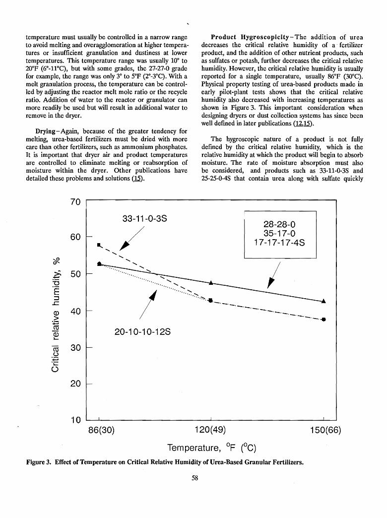
temperature must usually be controlled in a narrow rangeto avoid melting and overagglomeration at higher temperatures or insufficient granulation and dustiness at lowertemperatures. This temperature range was usually 10° to20°F (6°-11°C), but with some grades, the 27-27-0 gradefor example, the range was only 3° to 5°F (2°_3°C). With amelt granulation process, the temperature can be controlled by adjusting the reactor melt mole ratio or the recycleratio. Addition of water to the reactor or granulator canmore readily be used but will result in additional water toremove in the dryer.
Drying- Again, because of the greater tendency formelting, urea-based fertilizers must be dried with morecare than other fertilizers, such as ammonium phosphates.It is important that dryer air and product temperaturesare controlled to eliminate melting or reabsorption ofmoisture within the dryer. Other publications havedetailed these problems and solutions (15).
Product Hygroscopicity - The addition of ureadecreases the critical relative humidity of a fertilizerproduct, and the addition of other nutrient products, suchas sulfates or potash, further decreases the critical relativehumidity. However, the critical relative humidity is usuallyreported for a single temperature, usually 86°F (30°C).Physical property testing of urea-based products made inearly pilot-plant tests shows that the critical relativehumidity also decreased with increasing temperatures asshown in Figure 3. This important consideration whendesigning dryers or dust collection systems has since beenwell defmed in later publications (12,15).
The hygroscopic nature of a product is not fullydefined by the critical relative humidity, which is therelative humidity at which the product will begin to absorbmoisture. The rate of moisture absorption must alsobe considered, and products such as 33-11-0-35 and25-25-0-4S that contain urea along with sulfate quickly
70
20-1 0-1 0-128
28-28-035-17-0
17-17-17-48
'" ............. .......". .......
I········~·:':':·~
...,:,:-...._._._._._._._._._.-.--..--. ..
33-11-0-38
/60
.~ 50"C
E:::1
.r:::Q) 40>~roQ)"-
ro 30(.)
':;:j.~
()
20
1086(30) 120(49)
Tern perature, OF (oC)
150(66)
Figure 3. Effect of Temperature on Critical Relative Humidity of Urea-Based Granular Fertilizers.
58
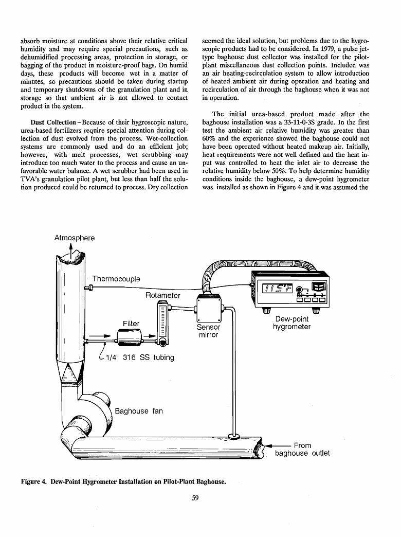
absorb moisture at conditions above their relative criticalhumidity and may require special precautions, such asdehumidified processing areas, protection in storage, orbagging of the product in moisture-proof bags. On humiddays, these products will become wet in a matter ofminutes, so precautions should be taken during startupand temporary shutdowns of the granulation plant and instorage so that ambient air is not allowed to contactproduct in the system.
Dust Collection - Because of their hygroscopic nature,urea-based fertilizers require special attention during collection of dust evolved from the process. Wet-collectionsystems are commonly used and do an efficient job;however, with melt processes, wet scrubbing mayintroduce too much water to the process and cause an unfavorable water balance. A wet scrubber had been used inTVA's granulation pilot plant, but less than half the solution produced could be returned to process. Dry collection
seemed the ideal solution, but problems due to the hygroscopic products had to be considered. In 1979, a pulse jettype baghouse dust collector was installed for the pilotplant miscellaneous dust collection points. Included wasan air heating-recirculation system to allow introductionof heated ambient air during operation and heating andrecirculation of air through the baghouse when it was notin operation.
The initial urea-based product made after thebaghouse installation was a 33-11-0-3S grade. In the frrsttest the ambient air relative humidity was greater than60% and the experience showed the baghouse could nothave been operated without heated makeup air. Initially,heat requirements were not well defined and the heat input was controlled to heat the inlet air to decrease therelative humidity below 50%. To help determine humidityconditions inside the baghouse, a dew-point hygrometerwas installed as shown in Figure 4 and it was assumed the
Thermocouple
Rotameter
I I 1/4" 316 SS tubing~_-:l1
Baghouse fan
Sensormirror
Dew-pointhygrometer
Figure 4. Dew-Point Hygrometer Installation on Pilot-Plant Baghouse.
59
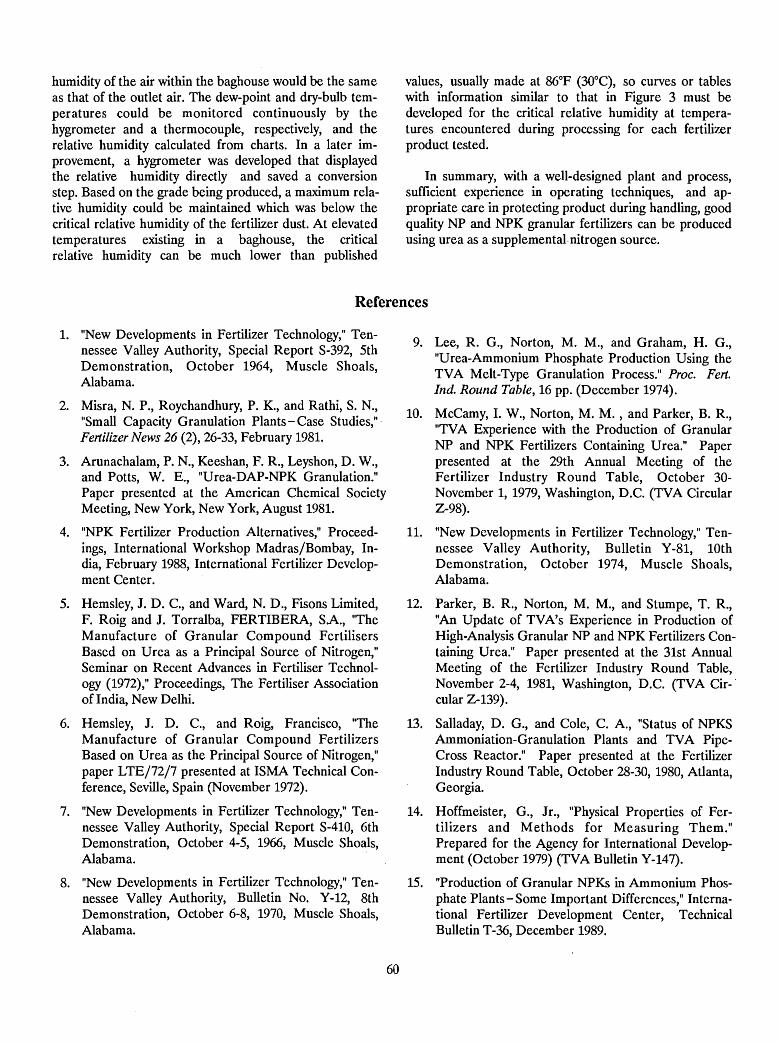
humidity of the air within the baghouse would be the sameas that of the outlet air. The dew-point and dry-bulb temperatures could be monitored continuously by thehygrometer and a thermocouple, respectively, and therelative humidity calculated from charts. In a later improvement, a hygrometer was developed that displayedthe relative humidity directly and saved a conversionstep. Based on the grade being produced, a maximum relative humidity could be maintained which was below thecritical relative humidity of the fertilizer dust. At elevatedtemperatures existing in a baghouse, the criticalrelative humidity can be much lower than published
values, usually made at 86°F (30°C), so curves or tableswith information similar to that in Figure 3 must bedeveloped for the critical relative humidity at temperatures encountered during processing for each fertilizerproduct tested.
In summary, with a well-designed plant and process,sufficient experience in operating techniques, and appropriate care in protecting product during handling, goodquality NP and NPK granular fertilizers can be producedusing urea as a supplemental·nitrogen source.
References
1. "New Developments in Fertilizer Technology," Tennessee Valley Authority, Special Report S-392, 5thDemonstration, October 1964, Muscle Shoals,Alabama.
2. Misra, N. P., Roychandhury, P. K., and Rathi, S. N.,"Small Capacity Granulation Plants-Case Studies,'"Fertilizer News 26 (2), 26-33, February 1981.
3. Arunachalam, P. N., Keeshan, F. R., Leyshon, D. W.,and Potts, W. E., "Urea-DAP-NPK Granulation."Paper presented at the American Chemical SocietyMeeting, New York, New York, August 1981.
4. "NPK Fertilizer Production Alternatives," Proceedings, International Workshop Madras/Bombay, India, February 1988, International Fertilizer Development Center.
5. Hemsley, J. D. C., and Ward, N. D., Fisons Limited,F. Roig and J. Torralba, FERTIBERA, SA., "TheManufacture of Granular Compound FertilisersBased on Urea as a Principal Source of Nitrogen,"Seminar on Recent Advances in Fertiliser Technology (1972)," Proceedings, The Fertiliser Associationof India, New Delhi.
6. Hemsley, J. D. C., and Roig, Francisco, "TheManufacture of Granular Compound FertilizersBased on Urea as the Principal Source of Nitrogen,"paper LTE/72/7 presented at ISMA Technical Conference, Seville, Spain (November 1972).
7. "New Developments in Fertilizer Technology," Tennessee Valley Authority, Special Report S-410, 6thDemonstration, October 4-5, 1966, Muscle Shoals,Alabama.
8. "New Developments in Fertilizer Technology," Tennessee Valley Authority, Bulletin No. Y-12, 8thDemonstration, October 6-8, 1970, Muscle Shoals,Alabama.
60
9. Lee, R. G., Norton, M. M., and Graham, H. G.,"Urea-Ammonium Phosphate Production Using theTVA Melt-Type Granulation Process." Proc. Fert.Ind. Round Tab/e, 16 pp. (December 1974).
10. McCamy, I. W., Norton, M. M. , and Parker, B. R.,"TVA Experience with the Production of GranularNP and NPK Fertilizers Containing Urea." Paperpresented at the 29th Annual Meeting of theFertilizer Industry Round Table, October 30November 1,1979, Washington, D.C. (TVA CircularZ-98).
11. "New Developments in Fertilizer Technology," Tennessee Valley Authority, Bulletin Y-81, 10thDemonstration, October 1974, Muscle Shoals,Alabama.
12. Parker, B. R., Norton, M. M., and Stumpe, T. R.,"An Update of TVA's Experience in Production ofHigh-Analysis Granular NP and NPK Fertilizers Containing Urea." Paper presented at the 31st AnnualMeeting of the Fertilizer Industry Round Table,November 2-4, 1981, Washington, D.C. (TVA Cir-'cular Z-139).
13. Salladay, D. G., and Cole, C. A., "Status of NPKSAmmoniation-Granulation Plants and TVA PipeCross Reactor." Paper presented at the FertilizerIndustry Round Table, October 28-30, 1980, Atlanta,Georgia.
14. Hoffmeister, G., Jr., "Physical Properties of Fertilizers and Methods for Measuring Them."Prepared for the Agency for International Development (October 1979) (TVA Bulletin Y-147).
15. "Production of Granular NPKs in Ammonium Phosphate Plants - Some Important Differences," International Fertilizer Development Center, TechnicalBulletin T-36, December 1989.
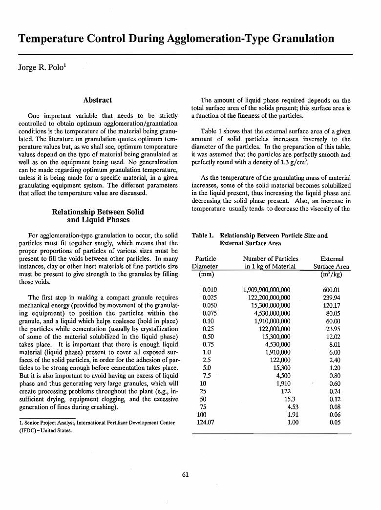
Temperature Control During Agglomeration-Type Granulation
Jorge R. PoIo1
Abstract
One important variable that needs to be strictlycontrolled to obtain optimum agglomeration/granulationconditions is the temperature of the material being granulated. The literature on granulation quotes optimum temperature values but, as we shall see, optimum temperaturevalues depend on the type of material being granulated aswell as on the equipment being used. No generalizationcan be made regarding optimum granulation temperature,unless it is being made for a specific material, in a givengranulating equipment system. The different parametersthat affect the temperature value are discussed.
Relationship Between Solidand Liquid Phases
The amount of liquid phase required depends on thetotal surface area of the solids present; this surface area isa function of the fmeness of the particles.
Table 1 shows that the external surface area of a givenamount of solid particles increases inversely to thediameter of the particles. In the preparation of this table,it was assumed that the particles are perfectly smooth andperfectly round with a density of 1.3 g/cm3
•
As the temperature of the granulating mass of materialincreases, some of the solid material becomes solubilizedin the liquid present, thus increasing the liquid phase anddecreasing the solid phase present. Also, an increase intemperature usually tends to decrease the viscosity of the
Table 1. Relationship Between Particle Size andExternal Surface Area
For agglomeration-type granulation to occur, the solidparticles must fit together snugly, which means that theproper proportions of particles of various sizes must bepresent to fill the voids between other particles. In manyinstances, clay or other inert materials of fine particle sizemust be present to give strength to the granules by fillingthose voids.
The first step in making a compact granule requiresmechanical energy (provided by movement of the granulating equipment) to position the particles within thegranule, and a liquid which helps coalesce (hold in place)the particles while cementation (usually by crystallizationof some of the material solubilized in the liquid phase)takes place. It is important that there is enough liquidmaterial (liquid phase) present to cover all exposed surfaces of the solid particles, in order for the adhesion of particles to be strong enough before cementation takes place.But it is also important to avoid having an excess of liquidphase and thus generating very large granules, which willcreate processing problems throughout the plant (e.g., insufficient drying, equipment clogging, and the excessivegeneration of fines during crushing).
1. Senior Project Analyst, International Fertilizer Development Center
(IFDC) - United States.
61
ParticleDiameter
(mm)
0.0100.0250.0500.0750.100.250.500.751.02.55.07.5
10255075
100124.07
Number of Particlesin 1 kg of Material
1,909,900,000,000122,200,000,00015,300,000,0004,530,000,0001,910,000,000
122,000,00015,300,0004,530,0001,910,000
122,00015,3004,5001,910
12215.34.531.911.00
ExternalSurface Area
(m2/kg)
600.01239.94120.1780.0560.0023.9512.028.016.002.401.200.800.600.240.120.080.060.05
t(])~
:::J......co~
Q)0...E(])......
"'0(])(/)
co(])~
()C
Excessive Fluidity
Granulation curve
Granulation area
Insufficient Fluidity
Increased water content ..
Figure 1. Relationship of Temperature and Water Content to Optimum Granulation.
liquid phase. The net result is that the required amount ofliquid phase, for optimum granulation, varies with the temperature of granulation as shown in Figure 1.
Table 2. Typical Granulation Temperatures forNPK Products
There are, however, limits to the ternperature for optimum granulation. A system that is too cold will fail todissolve enough material into the required liquid phase.Therefore, even if the granules are well formed in thegranulator, as the water evaporates out of the granule inthe dryer, the solid particles will dissociate because thereis nothing holding them together. If the temperature istoo high, there will be a tendency to overgranulate. Sometypical granulation temperatures are shown in Table 2.
Typical superphosphate-based formulations
Urea-based 17-17-17 using a preneutralizer
Urea-based 17-17-17-2MgO without use ofpreneutralizer; reacting 20% of the P20S(in the form of phosphoric acid) directly inthe granulator
Controlling the Temperature During GranulationIt is important at this point to stress the difference be
tween temperature and heat. According to the dictionary,ternperature is the degree of hotness or coldness of abody, measured on a definite scale, whereas heat is a formof energy that causes substances to rise in temperature,fuse, evaporate, expand, or undergo various other related
62
Urea-based 17-17-17-2MgO with no chemical 53°Creactions
Urea-based 14-6-21-4MgO with phosphate 52°Crock (no chemical reactions)
changes. To control temperature, we have to control theheat balance within the granulator. For the temperatureto remain constant, the inputs of heat to the granulatormust equal the heat output or losses from the granulator.
Heat enters the granulator in one or more of the following ways:
• Sensible heat introduced by the ingredients and steam.This is the heat that is related to the quantity and temperature level of these materials.
• Heat generated by chemical reactions which take placewithin the granulator. Some reactions are endothermic rather than exothermic; in these cases the heatprovided will be negative, reducing the temperature ofthe granulating mass.
• Latent heat of vaporization for condensing steam.This is the heat ijberated by steam when it condenses,which is essentially equivalent to heat that was given tothe water to turn it into steam in the rust place.
• Heat of crystallization of salts that form. Usually thisis a positive value.
Heat leaves the granulatpt: in one or more of the following ways:
• Sensible heat carried by the granulator dischargematerial and gases that are vented. This is again theheat related to the quantity and temperature level ofthe materials leaving the granulator.
• Latent heat of vaporization for evaporated water. Thisis the heat consumed by the water that evaporates andleaves the granulator as steam.
• Sensible heat lost to the environment. This is the heatlost from the granulator by convection, radiation, andconduction.
For granulators of a given geometric configuration andsize, the sensible heat lost to the environment will be afunction of the temperatures of the granulating mass andthe environment. If these temperatures are held at similarvalues, the losses can be considered to be the same, andconstant. Also, the losses of sensible heat carried by thegranulator discharge material and vented gases for a giventype of granulation operation will be similar at a similargranulating temperature and production rate. Therefore,to maintain a constant ternperature in a given granulatorwhere the ingredients are entering at similar quantitiesand temperatures, it will be necessary to control the otherheat input/output variables, which include the heat
63
generated by chemical reactions; the heat of crystallizationof salts that form; and the latent heat of vaporization forcondensed steam and evaporated water.
If the ternperature begins to increase, it will be neces'sary to perform at least one of the following tasks to maintain the temperature at the desired level.
• Decrease the amount of steam being used.
• Increase the recycle-to-product ratio to cool thegranulator.
• Displace some chemical reaction from the granulatorto other vessels.
• Replace some of the solubilized or molten salts fed tothe granulator with solid material.
If during a granulation operation the temperaturebegins to decrease, it will be necessary to perform at leastone of the following tasks to maintain the temperature atthe desired level.
• Increase the amount of steam being used.
• Decrease the recycle-to-product ratio so as not to coolthe granulator as much.
• Increase the amount of chemical reactions taking placewithin the granulator.
• Replace some of the solid material fed to thegranulator with solubilized or molten salts. However,the water content of the salt solution must be sufficiently low to avoid cooling.
The ideal situation comes about when all other sourcesof heat are balanced and the operator has command overa discretionary amount of steam that can be used to increase or decrease the heat input and therefore temperature. The use of steam is very effective because it alsoaffects the liquid phase and thus is effective in two ways.
ammoniation reactions, using either gaseous or liquidammonia.
For heat calculation purposes, the values shown inTable 4 can be used to determine the amount of ammoniarequired for common ammoniation reactions.
Equipment for PerformingChemical Reactions
Other important values useful in heat calculations forurea-based NPK granulation are:
Tank-Type PreneutralizerDuring the early days of granulation, the granulator
was sufficient to handle the total heat inputs of theprocess. Later, with the use of phosphoric acid and theproduction of more concentrated products, the amount ofchemical reactions became too large for the granulator tohandle alone. Therefore, it became necessary to use a vessel (tank) for some preneutralization of the acidsbefore feeding them to the granulator. This equipment
57.8 kg-cal/kg
0.504 kg-cal/kgjOC0,41 kg-caljkg;aC
Melting point of urea
Heat of crystallization of urea
Specific heat (molten urea)Specific heat (solid urea)
The values shown in Table 3 can be used when calculating the heat generated during the occurrence of typical
Values to Consider WhenCalculating Heat Balances
The literature on granulation gives values of about45,000 to 50,000 kilogram-calories per tonne of product asan optimum heat input to a granulator. This value,however, holds more for the superphosphate-based formulations that were prevalent some years ago and for agiven type of process used for granulating these formulations. To determine the heat input required for optimumgranulation of other types of materials, tests have to beperformed using the actual type of granulating equipment.During these tests, different solid particle sizes, liquid-tosolid ratios, and recycle-to-product ratios should be tried,along with different temperatures, to obtain an adequatearray of results for analysis. The optimum conditionsshould consider production capacity, drying requirements,and product quality.
Table 3. Heat Released When Reacting Acid Materials With Ammonia
Reaction
Heat Released,kg-cal/kg NH3 Reacted
NIL Gas NH3 Liguid
Wet-process phosphoric acid (54% P20S) reacted to monoammoniumphosphate· (MAP)
Wet-process phosphoric acid (54% P20S) reacted to diammoniumphosphate (DAP)
MAP reacted to DAP
Triple superphosphate (TSP) reacted to ammoniated TSP
Single superphosphate (SSP) reacted to ammoniated SSP
Sulfuric acid reacted to ammonium sulfate
1,890 1,370
1,510 990
1,130 610
1,580 1,060
1,460 940
2,165 1,645
64
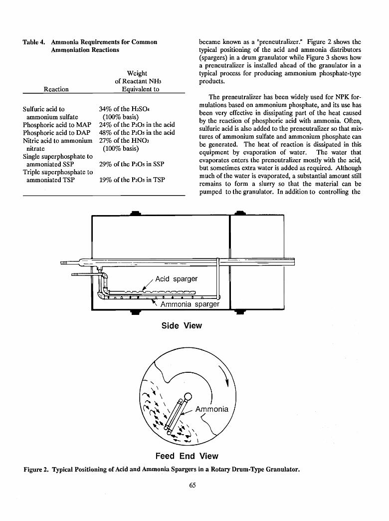
Table 4. Ammonia Requirements for CommonAmmoniation Reactions
Reaction
Sulfuric acid toammonium sulfate
Phosphoric acid to MAPPhosphoric acid to DAPNitric acid to ammonium
nitrateSingle superphosphate to
ammoniated SSPTriple superphosphate to
ammoniated TSP
Weightof Reactant NH3
Equivalent to
34% of the H2S04(100% basis)
24% of the P20S in the acid48% of the P20S in the acid27% of the HN03
(100% basis)
29% of the P20S in SSP
19% of the P20S in TSP
became known as a "preneutralizer." Figure 2 shows thetypical positioning of the acid and ammonia distributors(spargers) in a drum granulator while Figure 3 shows howa preneutralizer is installed ahead of the granulator in atypical process for producing ammonium phosphate-typeproducts.
The preneutralizer has been widely used for NPK formulations based on ammonium phosphate, and its use hasbeen very effective in dissipating part of the heat causedby the reaction of phosphoric acid with ammonia. Oftensulfuric acid is also added to the preneutralizer so that m~tures of ammonium sulfate and ammonium phosphate canbe generated. The heat of reaction is dissipated in thisequipment by evaporation of water. The water thatevaporates enters the preneutralizer mostly with the acid,but sometimes extra water is added as required. Althoughmuch of the water is evaporated, a substantial amount stillremains to form a slurry so that the material can bepumped to the granulator. In addition to controlling the
/ Acid sparger
-~~--
(I b, Ammonia sparger
Side View
Feed End View
Figure 2. Typical Positioning of Acid and Ammonia Spargers in a Rotary Drum-Type Granulator.
65
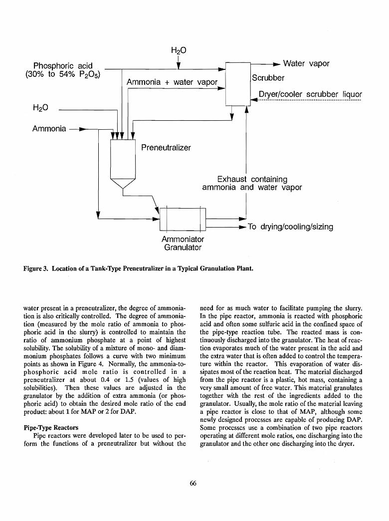
Ammonia + water vapor..
Phosphoric acid(30% to 54% P20 S)
H20
t _r--~---I:'. Water vapor--...------------L.-------1_~
Scrubber
Ammonia ----~-,.----,
- ,~'" l'Preneutralizer
'1
y Exhaust containingammonia and water vapor
'----------II~~ ;...
'-t------i---.J-------:-~To drying/cooling/sizing
ArnmoniatorGranulator
Figure 3. Location of a Tank-Type Preneutralizer in a Typical Granulation Plant.
water present in a preneutralizer, the degree of ammoniation is also critically controlled. The degree of ammoniation (measured by the mole ratio of ammonia to phosphoric acid in the slurry) is controlled to maintain theratio of ammonium phosphate at a point of highestsolubility. The solubility of a mixture of mono- and diammonium phosphates follows a curve with two minimumpoints as shown in Figure 4. Normally, the ammonia-tophosphoric acid mole ratio is controlled in apreneutralizer at about 0.4 or 1.5 (values of highsolubilities). Then these values are adjusted in thegranulator by the addition of extra ammonia (or phosphoric acid) to obtain the desired mole ratio of the endproduct: about 1 for MAP or 2 for DAP.
Pipe-Type ReactorsPipe reactors were developed later to be used to per
form the functions of a preneutralizer but without the
66
need for as much water to facilitate pumping the slurry.In the pipe reactor, ammonia is reacted with phosphoricacid and often some sulfuric acid in the confined space ofthe pipe-type reaction tube. The reacted mass is continuously discharged into the granulator. The heat of reaction evaporates much of the water present in the acid andthe extra water that is often added to control the temperature within the reactor. This evaporation of water dissipates most of the reaction heat. The material dischargedfrom the pipe reactor is a plastic, hot mass, containing avery small amount of free water. This material granulatestogether with the rest of the ingredients added to thegranulator. Usually, the mole ratio of the material leavinga pipe reactor is close to that of MAP, although somenewly designed processes are capable of producing DAP.Some processes use a combination of two pipe reactorsoperating at different mole ratios, one discharging into thegranulator and the other one discharging into the dryer.
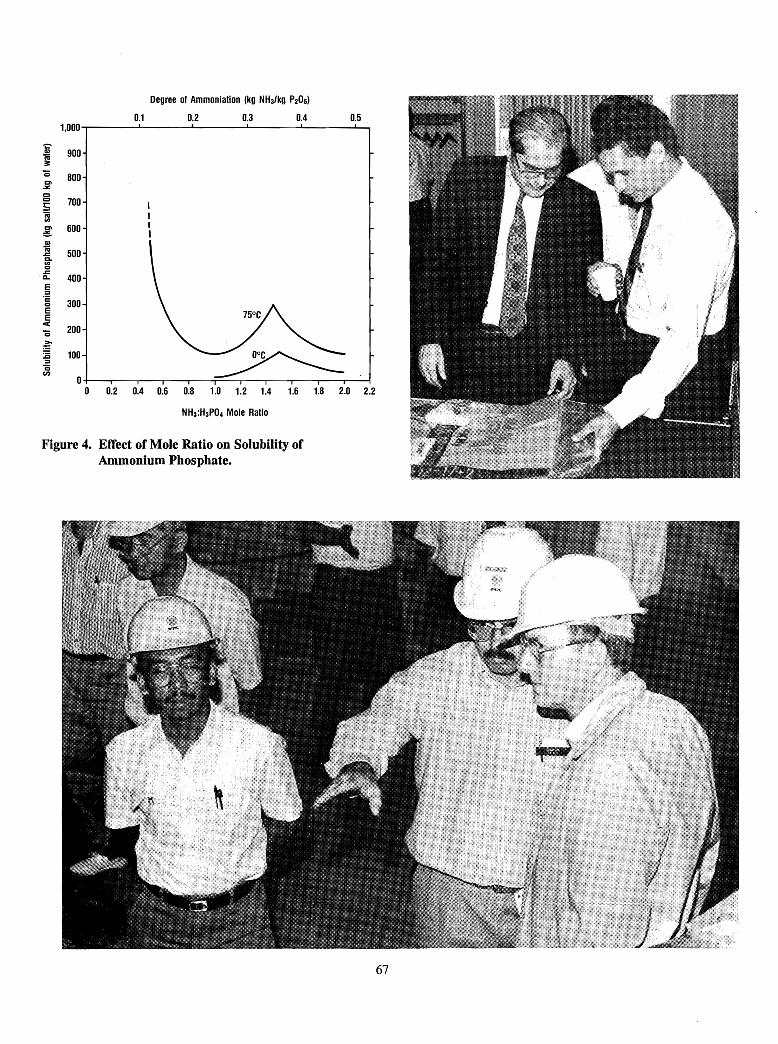
Degree of Ammoniation (kg NH3/kg PzOs)
0.1 0.2 0.3 0.4 0.51,000
"i:"CI) 900i63Q 800=.:.:00 700:;CQen
= 600CCI)
i6 500.cc.enQ.c
400n.E::J·c
300Q
EE<
200Q
:E100
~:c::J
Cen
00 0.2 0.4 0.6 0.8 1.0 1.2 1.4 1.6 1.8 2.0 2.2
NH3:H3P04 Mole Ratio
Figure 4. Effect of Mole Ratio on Solubility ofAmmonium Phosphate.
67
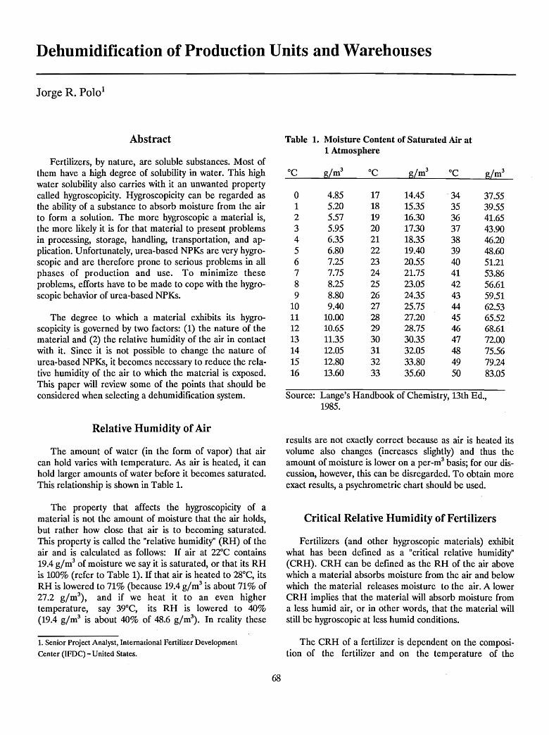
Dehumidification of Production Units and Warehouses
Jorge R. Polo1
Abstract
Fertilizers, by nature, are soluble substances. Most ofthem have a high degree of solubility in water. This highwater solubility also carries with it an unwanted propertycalled hygroscopicity. Hygroscopicity can be regarded asthe ability of a substance to absorb moisture from the airto form a solution. The more hygroscopic a material is,the more likely it is for that material to present problemsin processing, storage, handling, transportation, and application. Unfortunately, urea-based NPKs are very hygroscopic and are therefore prone to serious problems in allphases of production and use. To minimize theseproblems, efforts have to be made to cope with the hygroscopic behavior of urea-based NPKs.
The degree to which a material exhibits its hygroscopicity is governed by two factors: (1) the nature of thematerial and (2) the relative humidity of the air in contactwith it. Since it is not possible to change the nature ofurea-based NPKs, it becomes necessary to reduce the relative humidity of the air to which the material is exposed.This paper will review some of the points that should beconsidered when selecting a dehumidification system.
Relative Humidity ofAir
The amount of water (in the form of vapor) that aircan hold varies with temperature. As air is heated, it canhold larger amounts of water before it becomes saturated.This relationship is shown in Table 1.
The property that affects the hygroscopicity of amaterial is not the amount of moisture that the air holds,but rather how close that air is to becoming saturated.This property is called the "relative humidity" (RH) of theair and is calculated as follows: If air at 22°C contains19.4 g/m3 of moisture we say it is saturated, or that its RHis 100% (refer to Table 1). If that air is heated to 28°C, itsRH is lowered to 71% (because 19.4 g/m3 is about 71% of27.2 g/m3
), and if we heat it to an even highertemperature, say 39°C, its RH is lowered to 40%(19.4 g/m3 is about 40% of 48.6 g/m3
). In reality these
1. Senior Project Analyst, International Fertilizer Development
Center (IFDC) - United States.
68
Table 1. Moisture Content of Saturated Air at1 Atmosphere
°C g/m3 °C g/m3 °C g/m3
0 4.85 17 14.45 . 34 37.551 5.20 18 15.35 35 39.552 5.57 19 16.30 36 41.653 5.95 20 17.30 37 43.904 6.35 21 18.35 38 46.205 6.80 22 19.40 39 48.606 7.25 23 20.55 40 51.217 7.75 24 21.75 41 53.868 8.25 25 23.05 42 56.619 8.80 26 24.35 43 59.51
10 9.40 27 25.75 44 62.5311 10.00 28 27.20 45 65.5212 10.65 29 28.75 46 68.6113 11.35 30 30.35 47 72.0014 12.05 31 32.05 48 75.5615 12.80 32 33.80 49 79.2416 13.60 33 35.60 50 83.05
Source: Lange's Handbook of Chemistry, 13th Ed.,1985.
results are not exactly correct because as air is heated itsvolume also changes (increases slightly) and thus theamount of moisture is lower on a per-m3 basis; for our discussion, however, this can be disregarded. To obtain moreexact results, a psychrometric chart should be used.
Critical Relative Humidity of Fertilizers
Fertilizers (and other hygroscopic materials) exhibitwhat has been defined as a "critical relative humidity"(CRH). CRH can be defined as the RH of the air abovewhich a material absorbs moisture from the air and belowwhich the material releases moisture to the air. A lowerCRH implies that the material will absorb moisture froma less humid air, or in other words, that the material willstill be hygroscopic at less humid conditions.
The CRH of a fertilizer is dependent on the composition of the fertilizer and on the temperature of the
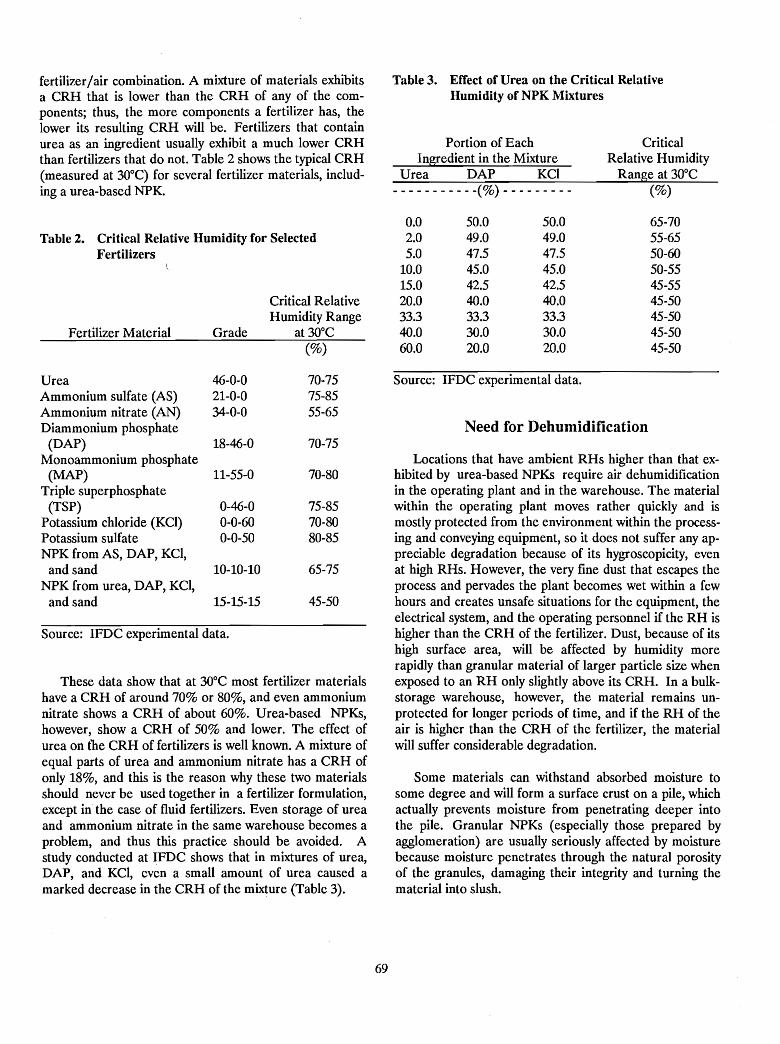
Table 3. Effect of Urea on the Critical RelativeHumidity of NPK Mixtures
fertilizer/ air combination. A mixture of materials exhibitsa CRH that is lower than the CRH of any of the components; thus, the more components a fertilizer has, thelower its resulting CRH will be. Fertilizers that containurea as an ingredient usually exhibit a much lower CRHthan fertilizers that do not. Table 2 shows the typical CRH(measured at 30°C) for several fertilizer materials, including a urea-based NPK.
Portion of EachIngredient in the Mixture
Urea DAP KCI- - - - - - - - - - -(%) - - - - - - - - -
CriticalRelative Humidity
Range at 30°C(%)
Need for Dehumidification
Some materials can withstand absorbed moisture tosome degree and will form a surface crust on a pile, whichactually prevents moisture from penetrating deeper intothe pile. Granular NPKs (especially those prepared byagglomeration) are usually seriously affected by moisturebecause moisture penetrates through the natural porosityof the granules, damaging their integrity and turning thematerial into slush.
Locations that have ambient RHs higher than that exhibited by urea-based NPKs require air dehumidificationin the operating plant and in the warehouse. The materialwithin the operating plant moves rather quickly and ismostly protected from the environment within the processing and conveying equipment, so it does not suffer any appreciable degradation because of its hygroscopicity, evenat high RHs. However, the very fine dust that escapes theprocess and pervades the plant becomes wet within a fewhours and creates unsafe situations for the equipment, theelectrical system, and the operating personnel if the RH ishigher than the CRH of the fertilizer. Dust, because of itshigh surface area, will be affected by humidity morerapidly than granular material of larger particle size whenexposed to an RH only slightly above its CRH. In a bulkstorage warehouse, however, the material remains unprotected for longer periods of time, and if the RH of theair is higher than the CRH of the fertilizer, the materialwill suffer considerable degradation.
Source: IFDC experimental data.
65-7055-6550-6050-5545-5545-5045-5045-5045-50
50.049.047.545.042.540.033.330.020.0
50.049.047.545.042.540.033.330.020.0
0.02.05.0
10.015.020.033.340.060.0
These data show that at 30°C most fertilizer materialshave a CRH of around 70% or 80%, and even ammoniumnitrate shows a CRH of about 60%. Urea-based NPKs,however, show a CRH of 50% and lower. The effect ofurea on the CRH of fertilizers is well known. A mixture ofequal parts of urea and ammonium nitrate has a CRH ofonly 18%, and this is the reason why these two materialsshould never be used together in a fertilizer formulation,except in the case of fluid fertilizers. Even storage of ureaand ammonium nitrate in the same warehouse becomes aproblem, and thus this practice should be avoided. Astudy conducted at IFDC shows that in mixtures of urea,DAP, and KCI, even a small amount of urea caused amarked decrease in the CRH of the mixture (Table 3).
Critical RelativeHumidity Range
Fertilizer Material Grade at 30°C(%)
Urea 46-0-0 70-75Ammonium sulfate (AS) 21-0-0 75-85Ammonium nitrate (AN) 34-0-0 55-65Diammonium phosphate
(DAP) 18-46-0 70-75Monoammonium phosphate
(MAP) 11-55-0 70-80Triple superphosphate
(TSP) 0-46-0 75-85Potassium chloride (KCI) 0-0-60 70-80Potassium sulfate 0-0-50 80-85NPKfromAS, DAP, KCI,
and sand 10-10-10 65-75NPK from urea, DAP, KCI,
and sand 15-15-15 45-50
Source: IFDC experimental data.
Table 2. Critical Relative Humidity for SelectedFertilizers
69
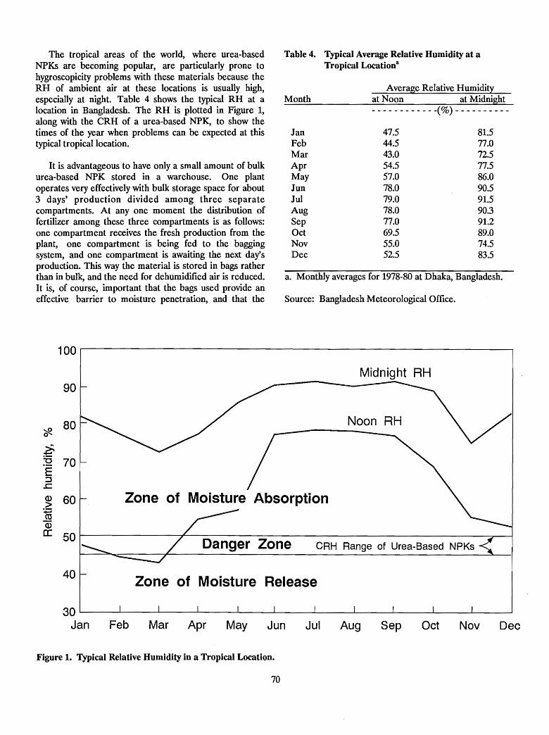
Source: Bangladesh Meteorological Office.
a. Monthly averages for 1978-80 at Dhaka, Bangladesh.
Table 4. Typical Average Relative Humidity at aTropical Location8
at Noon at Midnight
81.577.072.577.586.090.591.590.391.289.074.583.5
Average Relative Humidity
47.544.543.054.557.078.079.078.077.069.555.052.5
- - - - - - - - - - - -(%) - - - - - - - - - -
JanFebMarAprMayJunJulAugSepOctNovDec
Month
It is advantageous to have only a small amount of bulkurea-based NPK stored in a warehouse. One plantoperates very effectively with bulk storage space for· about3 days' production divided among three separatecompartments. At anyone moment the distribution offertilizer among these three compartments is as follows:one compartment receives the fresh production from theplant, one compartment is being fed to the baggingsystem, and one compartment is awaiting the next day'sproduction. This way the material is stored in bags ratherthan in bulk, and the need for dehumidified air is reduced.It is, of course, important that the bags used provide aneffective barrier to moisture penetration, and that the
The tropical areas of the world, where urea-basedNPKs are becoming popular, are particularly prone tohygroscopicity problems with these materials because theRH of ambient air at these locations is usually high,especially at night. Table 4 shows the typical RH at alocation in Bangladesh. The RH is plotted in Figure 1,along with the CRH of a urea-based NPK, to show thetimes of the year when problems can be expected at thistypical tropical location.
Zone of Moisture Absorption
Zone of Moisture Release
CRH Range of Urea-Based NPKs
Noon RH
Midnight RH
Danger Zone
100
90
cfl.80
~:2 70E:J.c(1) 60>~(1)
a: 50
40
DecNovOctSepAugJulJunMayAprMarFeb
30 L..--_--L.__----I..-__....I-__l--_---L.__.......L-__....I.-_----JL..--_-.1.__--L-_----l
Jan
Figure 1. Typical Relative Humidity in a Tropical Location.
70
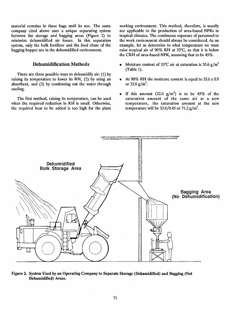
material remains in these bags until its usc. The samecompany cited above uses a unique separating systembetween the storage and bagging areas (Figure 2) tominimize dehumidified air losses. In this separationsystem, only the bulk fertilizer and the feed chute of thebagging hopper are in the dehumidified environment.
Dehumidification Methods
There are three possible ways to dehumidify air: (1) byraising its temperature to lower its RH, (2) by using anabsorbent, and (3) by condensing out the water throughcooling.
The frrst method, raising its temperatu.re, can be usedwhen the required reduction in RH is small. Otherwise,the required heat to be added is too high for the plant
working environment. This method, therefore, is usuallynot applicable to the production of urea-based NPKs intropical climates. The continuous exposure of personnel tothe work environment should always be considered. As anexample, let us determine to what temperature we mustraise .tropical air of 90% RH at 33°C, so that it is belowthe CRH of urea-based NPK, assuming that to be 45%.
• Moisture content of 33°C air at saturation is 35.6 g/m3
(Table 1).
• At 90% RH the moisture content is equal to 35.6 x 0.9or 32.0 g/m3
•
• If this amount (32.0 g/m3) is to be 45% of the
saturation amount of the same air at a newternperature, the saturation amount at the newtemperature will be 32.010.45 or 71.2 g/m3
•
.:.o 0 , •• \ •• :' ••••• , •• 1.0'. "•• ea' •••••••••••••• eO" .' ••••1 •••..:.;..:.:.=...;..:;,L.:.J..~........:..............;".,.",;.::.lj:.\
~.~
DehumidifiedBulk Storage Area
~::.,
Bagging Area(No Dehumidification)
Figure 2. System Used by an Operating Company to Separate Storage (Dehumidified) and Bagging (NotDehumidified) Areas.
71
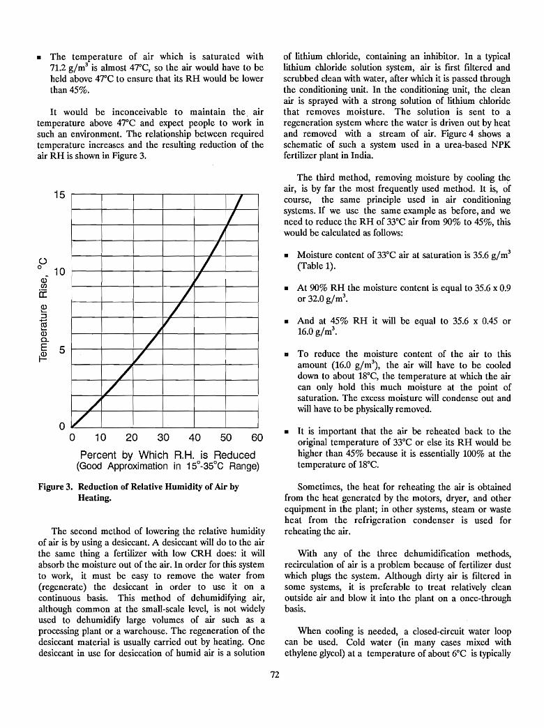
• The temperature of air which is saturated with71.2 g/m3 is almost 47°C, so the air would have to beheld above 47°C to ensure that its RH would be lowerthan 45%.
It would be inconceivable to maintain the. airtemperature above 47°C and expect people to work insuch an environment. The relationship between requiredtemperature increases and the resulting reduction of theair RH is shown in Figure 3.
of lithium chloride, containing an inhibitor. In a typicallithium cWoride solution system, air is first filtered andscrubbed clean with water, after which it is passed throughthe conditioning unit. In the conditioning unit, the cleanair is sprayed with a strong solution of lithium chloridethat removes moisture. The solution is sent to aregeneration system where the water is driven out by heatand removed with a stream of air. Figure 4 shows aschematic of such a system used in a urea-based NPKfertilizer plant in India.
• It is important that the air be reheated back to theoriginal temperature of 33°C or else its RH would behigher than 45% because it is essentially 100% at thetemperature of 18°C.
• At 90% RH the moisture content is equal to 35.6 x 0.9or 32.0 g/m3
•
• Moisture content of 33°C air at saturation is 35.6 g/m3
(Table 1).
• To reduce the moisture content of the air to thisamount (16.0 g/m3
) , the air will have to be cooleddown to about 18°C, the ternperature at which the aircan only hold this much moisture at the point ofsaturation. The excess moisture will condense out andwill have to be physically removed.
• And at 45% RH it will be equal to 35.6 x 0.45 or16.0 g/m3
•
The third method, removing moisture by cooling theair, is by far the most frequently used method. It is, ofcourse, the same principle used in air conditioningsystems. If we use the same example as before, and weneed to reduce the RH of 33°C air from 90% to 45%, thiswould be calculated as follows:
/1
1
/
I/
/Jif
//
~V
/V
//
/V
15
oo 10 20 30 40 50 60
Percent by Which R. H. is Reduced(Good Approximation in 1So-3SoC Range)
()0 10
Q)ena:Q)10-
::J-<U"-Q)Q.
E 5~
Figure 3. Reduction of Relative Humidity of Air byHeating.
The second method of lowering the relative humidityof air is by using a desiccant. A desiccant will do to the airthe same thing a fertilizer with low CRH does: it willabsorb the moisture out of the air. In order for this systemto work, it must be easy to remove the water from(regenerate) the desiccant in order to use it on acontinuous basis. This method of dehumidifying air,although common at the small-scale level, is not widelyused to dehumidify large volumes of air such as aprocessing plant or a warehouse. The regeneration of thedesiccant material is usually carried out by heating. Onedesiccant in use for desiccation of humid air is a solution
Sometimes, the heat for reheating the air is obtainedfrom the heat generated by the motors, dryer, and otherequipment in the plant; in other systems, steam or wasteheat from the refrigeration condenser is used forreheating the air.
With any of the three dehumidification methods,recirculation of air is a problem because of fertilizer dustwhich plugs the system. Although dirty air is filtered insome systems, it is preferable to treat relatively cleanoutside air and blow it into the plant on a once-throughbasis.
When cooling is needed, a closed-circuit water loopcan be used. Cold water (in many cases mixed withethylene glycol) at a temperature of about 6°C is typically
72
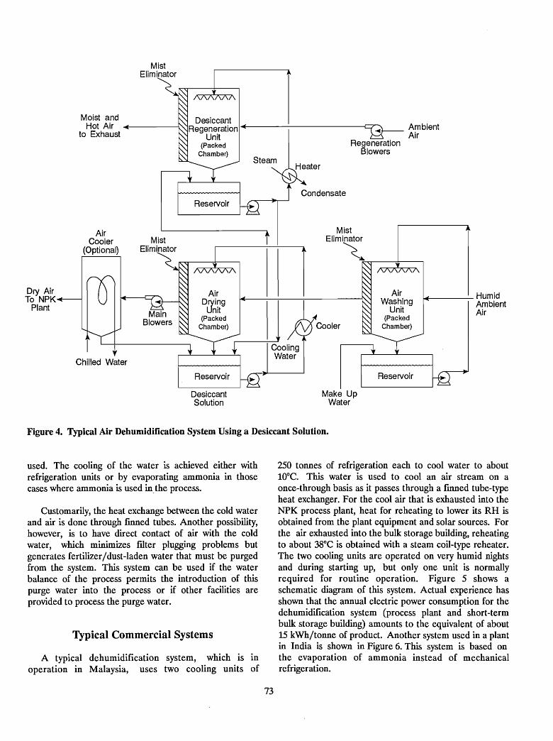
Moist andHot Air
to Exhaust
DesiccantRegeneration ...
Unit(Packed
Chamber)
Reservoir
~AmbientAir
RegenerationBlowers
Dry AirTo NPK
Plant
AirCooler
(Optional)
tChilled Water
Reservoir
DesiccantSolution
Make UpWater
AirWashing
Unit(Packed
Chamber)
Reservoir
f+----- HumidAmbientAir
Figure 4. Typical Air Dehumidification System Using a Desiccant Solution.
used. The cooling of the water is achieved either withrefrigeration units or by evaporating ammonia in thosecases where ammonia is used in. the process.
Customarily, the heat exchange between the cold waterand air is done through fmned tubes. Another possibility,however, is to have direct contact of air with the coldwater, which minimizes futer plugging problems butgenerates fertilizer/dust-laden water that must be purgedfrom the system. This system can be used if the waterbalance of the process permits the introduction of thispurge water into the process or if other facilities areprovided to process the purge water.
Typical Commercial Systems
A typical dehumidification system, which is inoperation in Malaysia, uses two cooling units of
73
250 tonnes of refrigeration each to cool water to about10°C. This water is used to cool an air stream on aonce-through basis as it passes through a finned tube-typeheat exchanger. For the cool air that is exhausted into theNPK process plant, heat for reheating to lower its RH isobtained from the plant equipment and solar sources. Forthe air exhausted into the bulk storage building, reheatingto about 38°C is obtained with a steam coil-type reheater.The two cooling units are operated on very humid nightsand during starting up, but only one unit is normallyrequired for routine operation. Figure 5 shows aschematic diagram of this system. Actual experience hasshown that the annual electric power consumption for thedehumidification system (process plant and short-termbulk storage building) amounts to the equivalent of about15 kWh/tonne of product. Another system used in a plantin India is shown in Figure 6. This system is based onthe evaporation of ammonia instead of mechanicalrefrigeration.
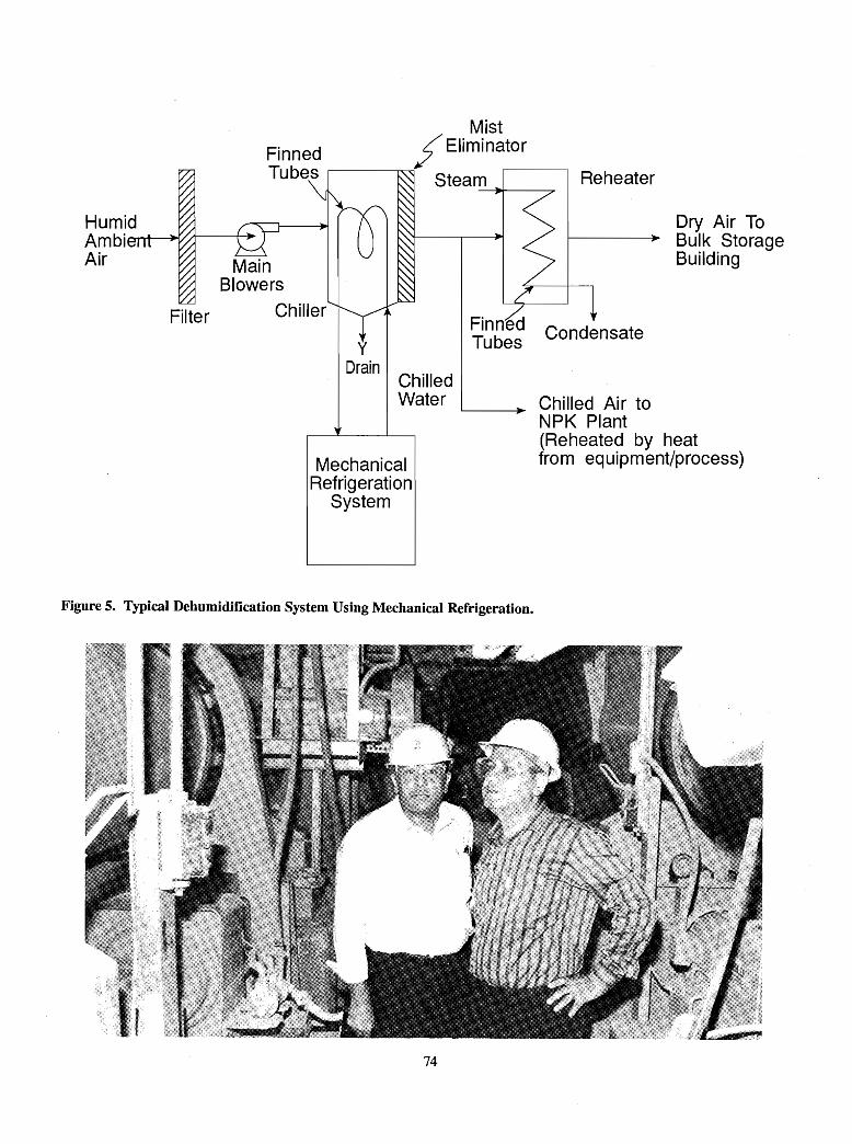
Reheater
Dry Air ToBulk StorageBuilding
Chilled Air toNPK Plant(Reheated by heatfrom equipment/process)
Finned CondensateTubesy
DrainChilledWater
MechanicalRefrigeration
System
MistFinned f Elimina...---to_r_----,Tubes ,--------r~ Steam
-----1111I----....."
MainBlowers
Filter Chiller
HumidAmbi~I'--""""J~/
Air
Figure 5. Typical Dehumidification System Using Mechanical Refrigeration.
74
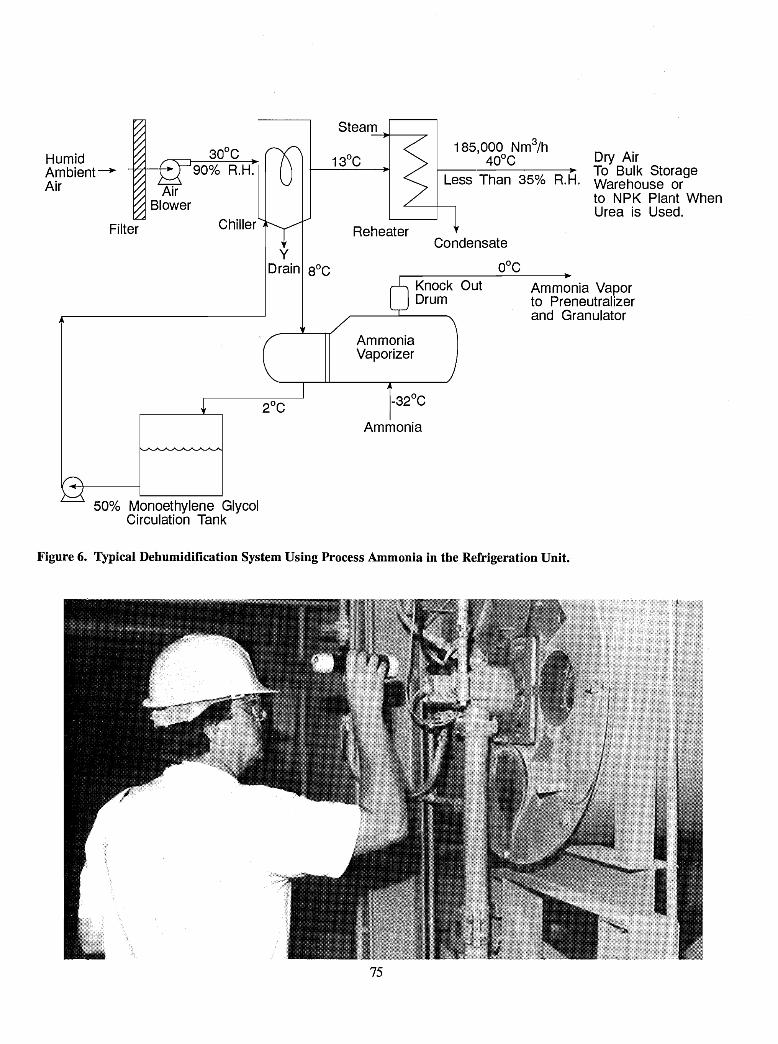
HumidArnbient~
Air
Filter
AirBlower
90% R.H.
Chiller
Steam~-----,..
185,000 Nm3/h400C Dry Air
Less Than 35% R.H. ~ar~~I~u;~O~geto NPK Plant WhenUrea is Used.
Reheater
50% Monoethylene GlycolCirculation Tank
yDrain SoC
Condensate
OOCKnock OutDrum
AmmoniaVaporizer
Ammonia
Ammonia Vaporto Preneutralizerand Granulator
Figure 6. Typical Dehumidification System Using Process Ammonia in the Refrigeration Unit.
75
Fertilizer Product Conditioning Agents - Emphasis on NPKs
David W. Rutland!
Abstract
This paper addresses the fertilizer manufacturers'responsibility to provide a product with good physicalproperties, including good flowability and storability, absence of caking, freedom from dust, and reasonable resistance to humidity. Causes and mechanisms of caking arediscussed, and various measures for decreasing the cakingtendency of fertilizers are outlined.
Introduction
It is the responsibility of the manufacturer to see thatthe consumer receives a quality fertilizer. A quality fertilizer should meet not only the specified nutrient requirements but also certain "expected" standards of physicalquality. Therefore, a fertilizer should be as free flowing,dust free, and nonhygroscopic as possible.
Fertilizers, between the time of production and fmalapplication to the soil, must be stored, either in bulk or inbags, for periods that can vary from less than a month to ayear or more. During this time it is essential that thematerials remain free flowing (noncaked). Unfortunately,many fertilizers, under certain conditions, tend to cakeinto hard lumps (1).
Causes of Caking
Caking of fertilizer is caused by the formation of contact points between the particles (granules, prills, tablets,briquettes, powder, or crystals). These contact points differ in nature and are usually divided into three types,namely, phase contacts, adhesive contacts, and liquidcontacts (~).
Phase contacts (salt bridges) are crystal bridgesformed at the contact points between the fertilizer particles. The most troublesome caking in the majot:~tyof fertilizers is believed to be caused by crystal bridging. Crystalbridges develop during storage as a result of continuing
1. Physical Properties Specialist, International Fertilizer Development
Center (IFDC) - United States.
76
chemical reactions, dissolution/recrystallization processes,and/or thermal effects.
Adhesive contacts are usually formed as a result ofplastic deformation and a bonding force due to capillaryadhesion. This type of contact is influenced mostly by theplasticity of the particles and the pressure exerted on thefertilizer material when it is stacked in bags or piled inbulk. This is usually referred to as bag or pile set, and thematerial normally reverts to a free-flowing form rathereasily with a minimal amount of handling.
Liquid contacts are due to considerable wetting of theproduct, which causes a ftlm of a saturated solution toform between particles. Formation of these types of contact points is defined as "sticking." Although such"sticking" has little strength, it is obviously undesirable because it can lead to salt bridging and hard caking.
Factors Influencing Caking
Caking in fertilizers can be influenced by a number offactors. These factors can be divided into internal factors,related to the physical-chemical constitution of thefertilizer, and external factors, related to the environmental conditions to which the fertilizer is exposed duringhandling and storage. Many of these factors areinterrelated (1,~,1;~).
Internal FactorsThe moisture content of the product is usually con
sidered to be the most important factor in promotingcaking. For most caking mechanisms, the presence of moisture, in the form of a solution phase, is essential.Generally, the higher the degree of drying at the time ofmanufacture, the less active the caking mechanisms willbe. The extent of drying required to effectively inactivatecaking mechanisms varies rather widely with the composition and physical makeup of the fertilizer (1). The general,consensus among experts is that the moisture content ofurea-based NP and NPK fertilizers should not exceed 1%and preferably should be 0.7% or less.
The chemical composition has an effect on the cakingtendency of a fertilizer. For example, it has been shownthat the caking tendency of ammonium nitrate-based and
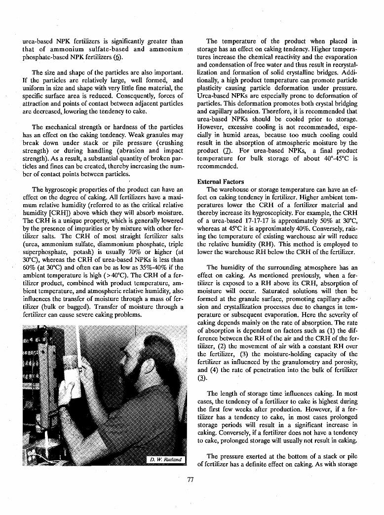
urea-bas~d NPK fertilizers is significantly greater thanthat of ammonium sulfate-based and ammoniumphosphate-based NPK fertilizers (Q).
The size and shape of the particles are also important.If the particles are relatively large, well formed, anduniform in size and shape with very little fine material, thespecific surface area is reduced. Consequently, forces ofattraction and points of contact between adjacent particlesare decreased,Jowering the tendency to cake.
The mechanical strength or hardness of the particleshas an effect on the caking tendency. Weak granules maybreak down under stack or pile pressure (crushingstrength) or during handling (abrasion and impactstrength). As a result, a substantial quantity of broken particles and fmes can be created, thereby increasing the number of cpntact points between particles.
The hygroscopic properties of the product can have aneffect on tqe degree of caking. All fertilizers have a maximum relative humidity (referred to as the critical relativehumidity [CRH]) above which' they will absorb moisture.The CRH is a unique property, which is generally loweredby the presence of impurities or by mixture with other fertilizer salts. The CRH of most straight fertilizer salts(urea, ammonium sulfate, diammonium phosphate, triplesU'perpho~phate, potash) is usually 70% or higher (at30°C), whereas the CRH of urea-based NPKs is less than60% (at 30°C) and often can be as low as 35%-40% if theambient temperature is high (>4O°C). The CRH of a fertilizer product, combined with product temperature, ambient temperature, and atmospheric relative humidity, alsoinfluences the transfer of moisture through a mass of fertilizer (bulk or bagged). Transfer of moisture through afertilizer can cause severe caking problems.
77
The temperature of the product when placed instorage has an effect on caking tendency. Higher temperatures increase the chemical reactivity and the evaporationand condensation of free water and thus result in recrystallization and formation of solid crystalline bridges. Additionally, a high product temperature can promote particleplasticity causing particle deformation under pressure.Urea-based NPKs are especially prone to deformation ofparticles. This deformation promotes both crystal bridgingand capillary adhesion. Therefore, it is recommended thaturea-based NPKs should be cooled prior to storage.However, excessive cooling is not recommended, especially in humid areas, because too much cooling couldresult in the absorption of atmospheric moisture by theproduct (1). For urea-based NPKs, a final producttemperature for bulk storage of about 40°-45°C isrecommended.
External FactorsThe warehouse or storage temperature can have an ef
fect on caking tendency in fertilizer. Higher ambient temperatures lower the CRH of a fertilizer material andthereby increase its hygroscopicity. For example, the CRHof a urea-based 17-17-17 is approximately 50% at 30°C,whereas at 45°C it is approximately 40%. Conversely, raising the temperature of existing warehouse air will reducethe relative humidity (RH). This method is employed tolower the warehouse RH below the CRH of the fertilizer.
The humidity of the surrounding atmosphere has aneffect on caking. As mentioned previously, when a fertilizer is exposed to a RH above its CRH, absorption ofmoisture will occur. Saturated solutions will then beformed at the granule surface, promoting capillary adhe.:sion and crystallization processes due to changes in temperature or subsequent evaporation. Here the severity ofcaking depends mainly on the rate of absorption. The rateof absorption is dependent on factors such as (1) the difference between the RH of the air and the CRH of the fertilizer, (2) the movement of air with a constant RH overthe fertilizer, (3) the moisture-holding capacity of thefertilizer as influenced by the granulometry and porosity,and (4) the rate of penetration into the bulk of fertilizer(~).
The length of storage time influences caking. In mostcases, the tendency of a fertilizer to cake is highest duringthe fust few weeks after production. However, if a fertilizer has a tendency to cake, in most cases. prolongedstorage periods will result in a significant increase incaking. Conversely, if a fertilizer does not have a tendencyto cake, prolonged storage will usually not result in caking.
The pressure exerted at the bottom of a stack or pileof fertilizer has a definite effect on caking. As with storage
time, if a fertilizer has a tendency to cake, excessive andprolonged pressure will result in a significant increase incaking. Under pressure, particle deformation may occur,resulting in increased contact area. Conversely, if a fertilizer does not have a tendency to cake, excessive andprolonged pressure (within reasonable limits) will usuallynot result in caking.
Solutions to Caking
The fertilizer industry has adopted various measures toalleviate caking, including the following:
1. The use of various drYing processes to obtain aproduct with a low moisture content.
2. The use of various cooling processes to obtain aproduct with a low temperature.
3. The use of various granulation, prilling, and pelletizingprocesses to produce larger particles thereby decreasing the surface area and number of contact points between particles.
4. The use of screening equipment to obtain a moreuniform particle size thereby decreasing the surfacearea and number of contact points between particles.
5. The control of storage conditions such as RH, temperature, pile height, and storage time.
6. Packaging fertilizer products in moisture-resistantbags.
7. The addition of anticaking agents (conditioners).
As indicated, much can be done to decrease the caking~ tendency by improving both process and storage conditions. However, there is always a practical and economicallimit to which the above measures can be used. Thus, inmany cases the use of an anticaking agent in combinationwith process and storage control· is the obvious answer tosolving most caking. problems. However, it should be emphasized here that an anticaking agent cannot be used tocompensate for poor production and storage practices.
How Anticaking Agents Work
Various modes of action have been suggested to explain how anticaking agents prevent caking. The followingmechanisms are commonly cited in the literature(1,~,3,~,~):
1. Preventing saturated solutions on the surfaces of twoadjacent particles from coming in contact.
2. Spreading of ,the crystallizing phase over the particlesurface.
3. Nucleation of small crystals during dissolution/recrystallization processes.
78
4. Modification of crystal makeup/behavior duringdissolution/ recrystallization processes.
5. Inhibition of dissolution/recrystallization processes.6. Creation of a hydrophobic barrier on the surface of the
particles.7. Decrease of capillary adhesion between particles.8. Drying of the granule surface.9. Decrease in the strength of salt bridges between
particles.
The mode of action that prevents caking in a particularfertilizer is determined predominantly by the type of anticaking agent used and to a lesser extent the type of fertilizer being conditioned. In most cases, more than oneanticaking mechanism is involved.
Types of Anticaking Agents
An anticaking agent (conditioner) is a material addedto a fertilizer to promote the maintenance of good physical condition (flowability) during storage and handling.Conditioners can be divided into two types, namely,(1) coating agents and (2) internal conditioners (1,3,~).
Coating AgentsCoating agents are conditioning materials that are ap
plied uniformly onto the surface of the fertilizer particles.Most coating agents are either very finely divided inertpowders that adhere to the particle surfaces or liquids thatare sprayed onto the surface. These anticaking agents function by various mechanisms.· Inert powders, such as kaolinclays (basic aluminum silicate), diatomaceousearth/kieselguhr (silica), talc (basic magnesium silicate),and chalk (calcium carbonate), function as mechanical barriers between particles and also serve to absorb, spread,
and inactivate any solution phase that may occur on particle surfaces. Where caking bonds do occur, the presenceof powder-type anticaking agents usually weakens thebonds; thus, caking is less severe. Liquid coating agentsusually function either as crystal modifiers to inhibit orweaken crystal growth on and between the particles or ashydrophobic barriers to inhibit moisture absorption.
Inert Powders - Clay anticaking agents are extremelyfme (typically 90% less than 10 J.Lm and 50% less than1 J.Lm) and thus adhere well to the fertilizer granules.Kaolin clays are widely available, relatively inexpensive,and are usually effective anticaking agents for NP andNPK fertilizers. Usually about 0.5%-1.0% by weight is required; however, this depends heavily upon the characteristics of the NPK fertilizer and the clay (1).
Diatomaceous earth (also referred to as kieselguhr) iscoarser than most clays (typically 90% minus 20 J.Lm and50% minus 3 J.Lm) and thus does not usually adhere to thefertilizer particles as well as clay. However, diatomaceousearth has good absorption properties and is an effectiveanticaking agent. Diatomaceous earth, talc, and chalk areless widely available than clays, and thus their use isusually localized. The major disadvantages to using inertpowders as anticaking agents are their diluting effect onthe product analysis and their dustiness.
Adherence of the powder to the NPK fertilizer can often be improved by adding a small amount of an oil orwax-type binder (0.1%-0.3%) and thus reducing dustiness.If an oil-type binder is used, all conveyor beltsdownstream from the binder addition system should be"oil-proof' to avoid ply separation and failure. Beltingmade from neoprene or polyvinyl chloride is not severelyaffected by oil-type binders or other organic-type conditioning agents (1). The use of oil-type binders onnitrate-type NPKs must be approached with cautionbecause of the tendency of organic materials to cause"cigar-burning" and decompos"ition with certain nitratecontaining·fertilizers.
Liquid Coating Agents - These agents include organicsurface active agents (surfactants) and nonsurface activea~ents.
Surfactants function by altering the interfacial tensionbetween· a solid and a liquid. Their action as anticakingagents is not clearly understood, and various mechanismshave been proposed, including protection from moisture,spreading of liquid film, modification of crystal
makeup/behavior, inhibition of dissolution and crystallization, and modification of bond tensile strength.
Because surfactant molecules comprise a nonpolarhydrophobic (water repellent) group and one or morepolar hydrophilic (having a strong affinity for water)groups, they can be subdivided into two classes accordingto their polar structure: (1) ionic, which can be furtherclassified according to th-e polarity of the charge carried
. on the active part of the molecule (anionic if the charge isnegative or cationic if the charge is positive), and(2) nonionic, where the molecule is electronically neutral.
The anionic surfactants most commonly employed aresulfonates. It is primarily due to their hydrophobic naturethat these anionic surfactants act as anticaking agents.
Cationic surfactants are dominated by the fatty amines,especially those with a long carbon chain like octadecyclamine. Caking is prevented by three differentmechanisms- forming a hydrophobic coating on the surface of the particles, and thus improving water repellency;reducing capillary adhesion between particles; and inhibiting nucleation or otherwise modifying crystal growth.
The largest class of nonionic surfactants is thepolyoxyethylene condensates, but these have only amoderate effect and are not widely used. Silicone· fluidsmay be considered as nonionic surfactants; although theyare used as anticaking agents for many powders, their useon fertilizers is limited due to their high cost.
Nonsurface active coating agents are organic compounds that do not exhibit surface activity but that form amoisture-resistant layer on the surface of the fertilizer particle. Typical nonsurface active coating agents includeparaffm wax, synthetic polymers, and oils. They can beused alone or in combination with an inert powder.
A number of companies market liquid coating agentsfor NPK fertilizer products (8). However, use of theseagents seems to be limited, probably because of their relatively high cost.
Internal or Chemical ConditionersThis type of conditioner (anticaking agent) is added to
the fertilizer during processing. These conditioners act· internally, usually as hardeners or crystal modifiers to improve storage properties. Such an anticakingagent has notbeen developed for use with NPK products. The multitudeof chemical compounds usually present in NPKs would
79
probably require a mixture of different crystal modifiers tobe effective. Internal conditioners are most effective on fertilizers containing predominantly one chemical compound.
A current popular practice in some countries is the inclusion of 0.3%-0.5% of formaldehyde in urea. Calcium lig- I
nosulfonate, added in small quantities to urea, effectivelyhardens/conditions urea as much as formaldehyde does.Another example is the use of magnesium nitrate (about2%) as an internal conditioner for ammonium nitrate.Also, fertilizer products (diammonium phosphate andmonoammonium phosphate) made from wet-process phosphoric acid characteristically contain significant quantitiesof iron and aluminum phosphate impurities. These impurities serve as effective internal conditioners in theseproducts. The iron and aluminum phosphates are found inthe products as amorphous "gels" that harden the productsand apparently immobilize the solution phase.
Method of ApplyingAnticaking Agents
The method used to apply anticaking agents to the fertilizer depends upon the fertilizer material being treatedand the anticaking agent being used. The anticakingagents must always be spread uniformly- on the particlesurface if the agent used is a coating agent or throughoutthe fertilizer if it is an internal conditioner. In certainmanufacturing processes, the treatment is an integral partof the process, whereas in others the anticaking treatmentmay be a separate operation.
Coating AgentsInert powders can be applied to' the fertilizer particles
by using a rotary coating drum located downstream fromthe screening and cooling equipment. In some cases theinert powder has been added to the fertilizer in the discharge section of a rotary cooler. This method is less common and generally less effective than employing aseparate coating drum.
80
Liquid coating agents, such as organic surfactants, canbe sprayed onto the fertilizer particles as they passthrough a rotary.coating drum. Other points in the processwhere liquid coating agents have been added are at theend of the product cooler, on the product belt, and at belttransfer points. Generally, a separate rotary coating drumis more effective in applying a uniform coating of powdersor liquid conditioners on fertilizers than any of the othermethods.
Internal ConditionersAs previously mentioned, formaldehyde has been used
for treatment of urea for many years. In most commercialurea prilling/granulation processes, the formaldehydeaddition point is either at the outlet of the second-stage·evaporator where the urea concentration is above 98.5%or at the inlet of the second-stage evaporator where theurea concentration is 95% or more.
As mentioned previously, probably the most popularinternal conditioner (stabilizing agent) used to preventparticle degradation and caking iti ammonium nitrate ismagnesium nitrate. The most common method of incorporating magnesium nitrate is to add it to the ammoniumnitrate liquor prior to evaporation. In addition to a stabilizing agent, ammonium nitrate usually requires a surfacecoating to eliminate caking.
Selection of Anticaking Agents
In selecting an appropriate anticaking agent for anNPK fertilizer, the following factors should be considered:
1. Anticaking effect of the agent.2. Availability of aIlticaking agent, its cost, and impact on
product analysis (dosage required).3. Method and equipment required for applying the an
ticaking agent. \4. Environmental and worker safety considerations.
References
1. "Using Anticaking Agents." 1983. Nitrogen, 146:2123, November-December.
2. Kurshinnikov, I. N., and G. F. Chelikidi. 1978."Methods of Eliminating the Caking of Fertilizers,"Proceedings of the Soviet-Swedish Symposium on theBeneficiation of Phosphate Rock, p. 180-186, Tallinn,Estonia.
3. Rosenblom, Jan, and Stig Zettervall. 1978."Anticaking Treatments of Granular Inorganic SaltsSuch as Phosphate Based Complex Fertilizers 'andAmmonium Nitrate," Proceedings of theSoviet-Swedish Symposium on the Beneficiation ofPhosphate Rock, p. 158-179, Tallinn, Estonia.
4. Hoffmeister, George. 1979. Physical Properties ofFertilizers and Methods for Measuring Them, Y-147,Tennessee Valley Authority, Muscle Shoals,Alabama, V.SA.
5. Thompson, D. C. 1972. Fertiliser Caking and ItsPrevention, Proceedings No. 125, The FertiliserSociety, London, V nited Kingdom.
6. Rutland, D. W., and J. R. Polo. 1989. "ComparativeProperties of Urea-Based NPK Fertilizers," INProceedings of the 39th Annual Meeting, TheFertilizer Industry Round Table, pp. 159-172,Atlanta, Georgia, V.SA.
7. Schultz, James J. 1989. Production of Granular NPKsin Ammonium Phosphate Plants-Some ImportantDifferences, Technical Bulletin T-36, InternationalFertilizer Development Center (IFDC), MuscleShoals, Alabama, U.SA.
8. Rutland, D. W. 1990. "Fertilizer Caking:Mechanisms, Influential Factors, and Methods ofPrevention," Paper presented at the 200th NationalMeeting of the American Chemical Society,Washington, D.C., V.SA.
9. Mackay, P. A., and K. S. Sharples. 1985. The Use ofSpecial Oils and Coatings to Prevent Caking ofFertilisers, Proceedings No. 239, The FertiliserSociety, London, Vnited Kingdom.
81
Storage and Handling Characteristics of Urea-BasedNPK Fertilizers
David W. Rutland!
Abstract
Quantitative data are given to compare the storage andhandling characteristics of urea-based NPK fertilizers withthose of other fertilizer materials, including non-ureaNPKs. In agreement with actual field experience, thesedata show that incorporation of urea in NP or NPK fertilizers can have quite troublesome effects on the storageand handling properties of the product. The major effectof the presence of urea is a lowering of the critical relativehumidity, which increases susceptibility of the product tomoisture absorption. Under even moderately humid atmospheric conditions, exposed pile surfaces become wetand flowability during field handling becomes degraded.The data confIrm the need for such precautions asdehumidification of production and storage areas andmoisture protection during field handling.
Introduction
The quality of a fertilizer product is basically judged bytwo criteria: (1) chemical properties and (2) physicalproperties. The chemical properties of a fertilizer(nutrient content, source, and availability to the crop) andtheir agronomic effectiveness are the ultimate reasons forthe use of a fertilizer. Good chemical properties of a fertilizer are ultimately reflected in their agronomicresponse. In contrast, the physical form of a fertilizerproduct and its ability to resist deterioration are importantwith respect to processing, handling, storage, field application, and agronomic response. This paper will focus principally on the storage and handling characteristics offertilizers, particularly urea-based NPKs.
The physical quality problems most frequently encountered during storage and handling of urea-based NPKs arecaking (agglomeration or lump formation), excessivehygroscopicity (moisture absorption and penetration), andto a lesser degree, dustiness and creation of fmes.
1. Physical Properties Specialist, International Fertilizer Development
Center (IFDC)- United States.
82
The presence of urea in solid NPK fertilizers usuallyhas an adverse effect on the storage and handlingproperties of the product when compared with· urea-freeNPKs. At the 1977 Fertilizer Industry Round Table Meeting' Hoffmeister and Harrison presented data on thestorage properties of various granular urea-based NP andNPK fertilizers (1); at the 1984 Round Table Meeting,Rutland compared the hygroscopic and storage propertiesof selected blended and granulated NPKs containing urea(~); then, at the 1985 Round Table Meeting, four paperswere presented dealing specifically with the granulation ofurea-based NPKs (~,~,~,Q); and, finally, during the RoundTable Meeting of 1989, Rutland and Polo presented dataon the hygroscopicity, storage, and process characteristicsof various urea-based NPKs (1). All these presentationsemphasized the problems that can be encountered in theprocessing, handling, and storage of urea-based NPKs.
Caking Tendency
A number of factors have an influence on the tendencyof a fertilizer to cake. These factors can be divided intointernal factors related to the physical-chemical composition of the fertilizer and external factors related to the environmental conditiqns to which the fertilizer is exposedduring storage and handling. Internal factors that affectthe tendency of a fertilizer to cake are (1) moisture content; (2) chemical composition; (3) particle size, shape,and structure; (4) mechanical strength; (5) hygroscopicproperties; and (6) product temperature. External factorsthat influence the tendency of a fertilizer to cake are(1) warehouse/storage temperature, (2) humidity of theatmosphere, (3) storage time, (4) storage pressure, and(5) handling techniques (8).
It is difficult to assign a degree of importance to thefactors that affect caking tendency, but it is generally perceived that the moisture content of a fertilizer product isthe single most important factor affecting caking. Formost caking mechanisms, the presence of moisture in theform of soluble salt solution phase is essential. Generally,the higher the degree of drying at the time of manufacture, the less active the caking mechanisms will :be. The
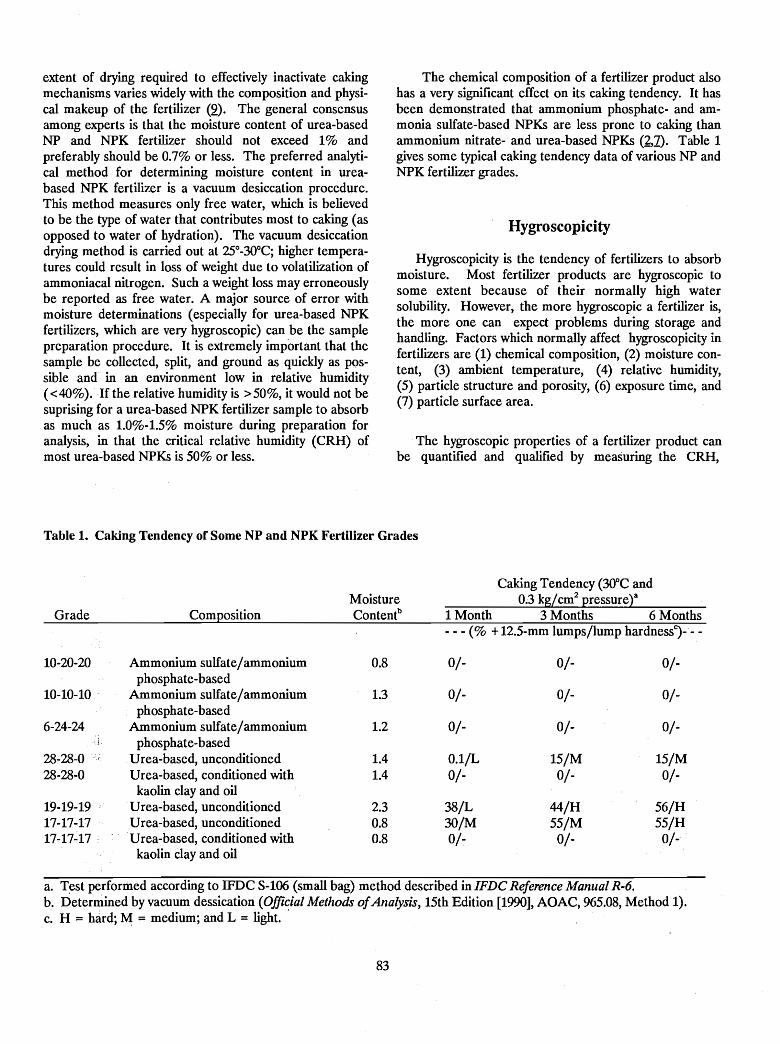
extent of drying required to effectively inactivate cakingmechanisms varies widely with the composition and physical makeup of the fertilizer (2). The general consensusamong experts is that the moisture content of urea-basedNP and NPK fertilizer should not exceed 1% andpreferably should be 0.7% or less. The preferred analytical method for determining moisture content in ureabased NPK fertilizer is a vacuum desiccation procedure.This method measures only free water, which is believedto be the type of water that contributes most to caking (asopposed to water of hydration). The vacuum desiccationdrying method is carried out at 25°_30°C; higher temperatures could result in loss of weight due to volatilization ofammoniacal nitrogen. Such a weight loss may erroneouslybe reported as free water. A major source of error withmoisture determinations (especially for urea-based NPKfertilizers, which are very hygroscopic) can be the samplepreparation procedure. It is extremely important that thesample be collected, split, and ground as quickly as possible and in an environment low in relative humidity( <40%).·If the relative humidity is >50%, it would not besuprising for a urea-based NPK fertilizer sample to absorbas much as 1.0%-1.5% moisture during preparation foranalysis, in that the critical relative humidity (CRH) ofmost urea-based NPKs is 50% or less.
The chemical composition of a fertilizer product alsohas a very significant effect on its caking tendency. It hasbeen demonstrated that ammonium phosphate- and ammonia sulfate-based NPKs are less prone to caking thanammonium nitrate- and urea-based NPKs (2,1). Table 1gives some typical caking tendency data of various NP andNPK fertilizer grades.
Hygroscopicity
Hygroscopicity is the tendency of fertilizers to absorbmoisture. Most fertilizer products are hygroscopic tosome extent because of their normally high watersolubility. However, the more hygroscopic a fertilizer is,the more one can expect problems during storage andhandling. Factors which normally affect hygroscopicity infertilizers are (1) chemical composition, (2) moisture content, (3) ambient temperature, (4) relative humidity,(5) particle structure and porosity, (6) exposure time, and(7) particle surface area.
The hygroscopic properties of a fertilizer product canbe quantified and qualified by measuring the CRH,
Table 1. Caking Tendency of Some NP and NPK Fertilizer Grades
Caking Tendency (30°C andMoisture 03 kg/cm2 pressuret
Grade Composition Contentb 1 Month 3 Months 6 Months- - - (% +12.5-mm lumps/lump hardnessJ- - -
10-20-20 Ammonium sulfate/ammonium 0.8 0/- 0/- 0/-phosphate-based
10-10-10 Ammonium sulfate/ammonium 1.3 0/- 0/- 0/-phosphate-based
6-24-24 Ammonium sulfate/ammonium 1.2 0/- 0/- 0/-. ~.' phosphate-based
28-28-0 -r Urea-based, unconditioned 1.4 O.I/L 15/M 15/M28-28-0 Urea-based, conditioned with 1.4 0/- 0/- 0/-
kaolin clay and oil19-19-19 .Urea-based, unconditioned 23 38/L 44/H 56/H17-17-17 Urea-based, unconditioned 0.8 3O/M 55/M 55/H17-17-17 : U rea-based, conditioned with 0.8 O/~ 0/- 0/-
kaolin clay and oil
a. Test performed according to IFDC S-I06(small bag) method described inIFDC Reference Manual R-6.b. Determined by vacuum dessication (Offi~ial Methods ofAnalysis, 15th Edition [1990], AOAC, 965.08, Method 1).c. H = hard; M = medium; and L = light.
83
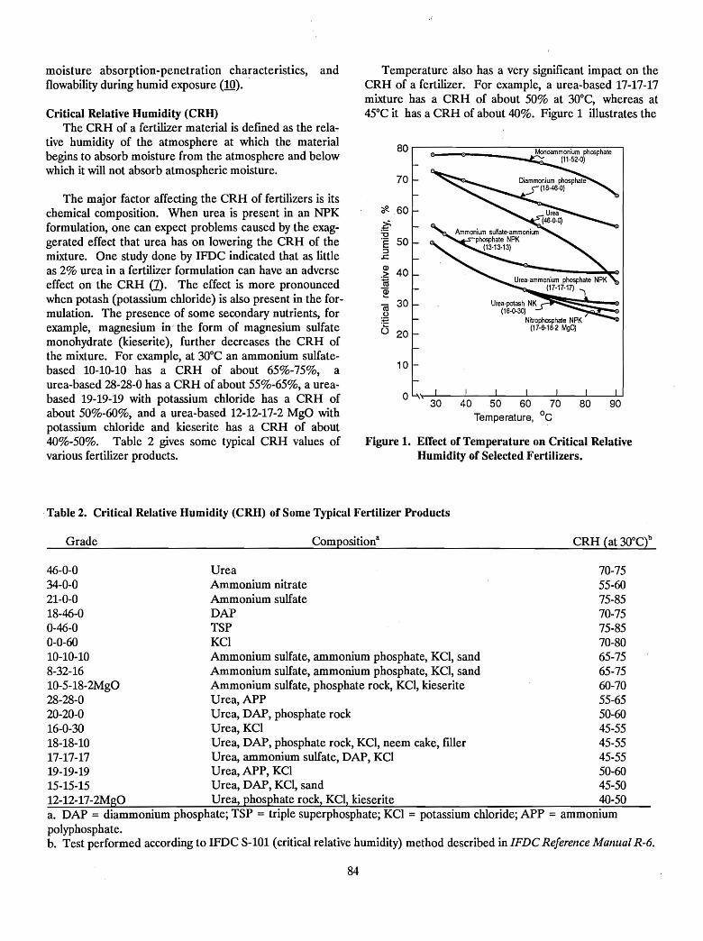
Urea-potash NK:?~:::::~;::~(16-0-30)
Nitrophosphale NPK(17-6-16-2 MgO)
10
ou..'"---'----'--.L--....L.--...........---'--_----'--'30 40 50 60 70 80 90
Temperature, °c
80 .---------------,~-.....,.......---,----:-.,....--,
70
"if!. 60;:.:0"E 50::J..c
.~ 40ca~«i 30.2.'!:::
o 20
Figure 1. Effect of Temperature on Critical RelativeHumidity of Selected Fertilizers•
Temperature also has a very significant impact on theCRR of a fertilizer. For example, a urea-based 17-17-17mixture has a CRR of about 50% at 30°C, whereas at45°C it has a CRR of about 40%. Figure 1 illustrates the
The major factor affecting the CRR of fertilizers is itschemical composition. When urea is present in an NPKformulation, one can expect problems caused by the exaggerated effect that urea has on lowering the CRR of themixture. One study done by IFDC indicated that as littleas 2% urea in a fertilizer formulation can have an adverseeffect on the CRR (1). The effect is more pronouncedwhen potash (potassium chloride) is also present in the formulation. The presence of some secondary nutrients, forexample, magnesium in'the form of magnesium sulfatemonohydrate (kieserite), further decreases the CRR ofthe mixture. For example, at 30°C an ammonium sulfatebased 10-10-10 has a CRR of about 65%-75%, aurea-based 28-28-0 has a CRR of about 55%-65%, a ureabased 19-19-19 with potassium chloride has a CRR ofabout 50%-60%, and a urea-based 12-12-17-2 MgO withpotassium chloride and kieserite has a CRR of about40%-50%. Table 2 gives some typical CRR values ofvarious fertilizer products.
Critical Relative Humidity (CRH)The CRR of a fertilizer material is defined as the rela
tive humidity of the atmosphere at which the materialbegins to absorb moisture from the atmosphere and belowwhich it will not absorb atmospheric moisture.
moisture absorption-penetration characteristics, andflowability during humid exposure (10).
.Table 2. Critical Relative Humidity (CRH) of Some Typical Fertilizer Products
Grade Composition8 CRR (at 3O°Ct
46-0-0 Urea 70-7534-0-0 Ammonium nitrate 55-6021-0-0 Ammonium sulfate 75-8518-46-0 DAP 70-750-46-0 TSP 75-850-0-60 KCI 70-8010-10-10 Ammonium sulfate, ammonium phosphate, KCI, sand 65-758-32-16 Ammonium sulfate, ammonium phosphate, KCI, sand 65-7510-5-18-2MgO Ammonium sulfate, phosphate rock, KCI, kieserite 60-7028-28-0 Urea, APP 55-6520-20-0 Urea, DAP, phosphate rock 50-6016-0-30 Urea, KCI 45-5518-18-10 Urea, DAP, phosphate rock, KCI, neem cake, filler 45-5517-17-17 Urea, ammonium sulfate, DAP, KCI 45-5519-19-19 Urea, APP, KCI 50-6015-15-15 Urea, DAP, KCI, sand 45-5012-12-17-2MgO Urea, phosphate rock, KCI, kieserite 40-50a. DAP = diammonium phosphate; TSP = triple superphosphate; KCI = potassium chloride; APP = ammoniumpolyphosphate.b. Test performed according to IFDC S-101 (critical relative humidity) method described in IFDC Reference Manual R-6.
84
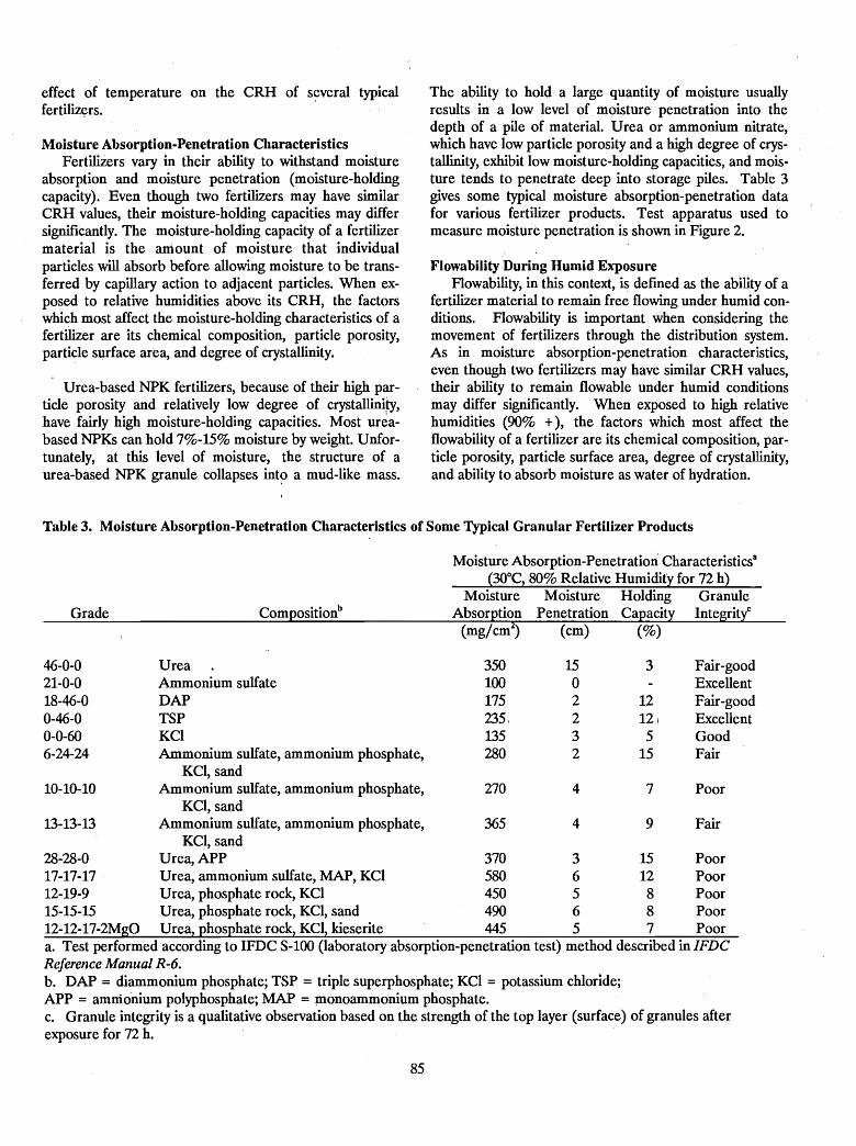
effect of temperature on the CRH of several typicalfertiliz~rs.
Moisture Absorption-Penetration CharacteristicsFertilizers vary in their ability to withstand moisture
absorption and moisture penetration (moisture-holdingcapacity). Even though two fertilizers may have similarCRH values, their moisture-holding capacities may differsignificantly. The moisture-holding capacity of a fertilizermaterial is the aniount of moisture that individualparticles will absorb before allowing moisture to be transferred by capillary action to adjacent particles. When exposed to relative humidities above its CRH, the factorswhich most affect the moisture-holding characteristics of afertilizer are its chemical composition, particle porosity,particle surface area, and degree of crystallinity.
Urea-based NPK fertilizers, because of their high particle porosity and relatively low degree of crystallini~,
have fairly high moisture-holding capacities. Most un~abased NPKs can hold 7%-15% moisture by weight. Unfortunately, at this level of moisture, the structure of aurea-based NPK granule collapses int~ a mud-like mass.
The ability to hold a large quantity of moisture usuallyresults in a low level of moisture penetration into thedepth of a pile of material. Urea or ammonium nitrate,which have low particle porosity and a high degree of crystallinity, exhibit low moisture-holding capacities, and moisture tends to penetrate deep into storage piles. Table 3gives some typical moisture absorption-penetration datafor various fertilizer products. Test apparatus used tomeasure moisture penetration is shown in Figure 2.
FlowabilityDuring Humid ExposureFlowability, in this context, is defmed as the ability of a
fertilizer material to remain free flowing under humid conditions. Flowability is important when considering themovement of fertilizers through the distribution system.As in moisture absorption-penetration characteristics,even though two fertilizers may have similar CRH values,their ability to remain flowable under humid conditionsmay differ significantly. When exposed to high relativehumidities (90% +), the factors which most affect theflowability of a fertilizer are its chemical composition, particle porosity, particle surface area, degree of crystallinity,and ability to absorb moisture as water of hydration.
Table 3. Moisture Absorption-Penetration Characteristics of Some Typical Granular Fertilizer Products
Moisture Absorption-Penetration Characteristicsa
(30°C, 80% Relative Humidity for 72 h)
Grade Compositionb
(mg/cm2) (cm) (%)
Poor
Fair
Fair-goodExcellentFair-goodExcellentGoodFair
9
7
3
1212i5
15
4
4
15o2232
270
365
350100175235,135280
UreaAmmonium sulfateDAPTSPKCIAmmonium sulfate, ammonium phosphate,
KCI, sandAmmonium sulfate, ammonium phosphate,
KCI, sandAmmonium sulfate, ammonium phosphate,
KCI, sand28-28-0 Urea, APP 370 3 15 Poor17-17-17 Urea, ammonium sulfate, MAP, KCI 580 6 12 Poor12-19-9 Urea, phosphate rock, KCI 450 5 8 Poor15-15-15 Urea, phosphate rock, KCI, sand 490 6 8 Poor12-12-17-2MgO Urea, phosphate rock, KCI, kieserite 445 5 7 Poora. Test performed according to IFDC S-100 (laboratory absorption-penetration test) method described in IFDCReference Manual R-6.b. DAP = diammonium phosphate; TSP = triple superphosphate; KCI = potassium chloride;APP = ammonium polyphosphate; MAP = monoammonium phosphate.c. Granule integrity is a qualitative observation based on the strength of the top layer (surface) of granules afterexposure for 72 h.
46-0-021-0-018-46-00-46-00-0-606-24-24
10-10-10
13-13-13
85
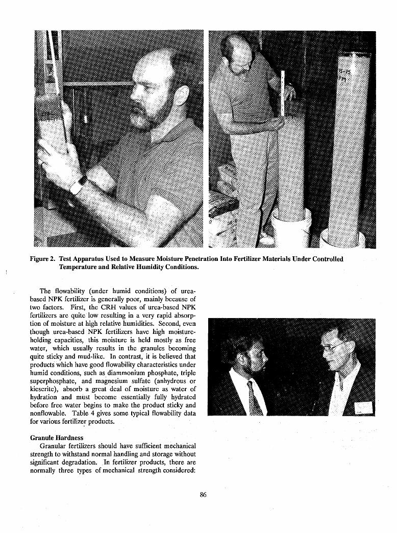
Figure 2. Test Apparatus Used to Measure Moisture Penetration Into Fertilizer Materials Under ControlledTemperature and Relative HUlnidity Conditions.
The flowability (under humid conditions) of ureabased NPK fertilizer is generally poor, mainly because oftwo factors. First, the eRR values of urea-based NPKfertilizers are quite low resulting in a very rapid absorption of moisture at high relative humidities. Second, eventhough urea-based NPK fertilizers have high moistureholding capacities, this moisture is held mostly as freewater, which usually results in the granules becomingquite sticky and mud-like. In contrast, it is believed thatproducts which have good flowability characteristics underhumid conditions, such as diammonium phosphate, triplesuperphosphate, and magnesium sulfate (anhydrous orkieserite), absorb a great deal of moisture as water ofhydration and must become essentially fully hydratedbefore free water begins to make the product sticky andnonflowable. Table 4 gives some typical flowability datafor various fertilize! products.
Granule HardnessGranular fertilizers should have sufficient mechanical
strength to withstand normal handling and storage withoutsignificant degradation. .In fertilizer products, there arenormally three types of mechanical strength considered:
86
Table 4. Flowability (During Humid Exposure) of Some Typical Granular Fertilizer Products
a. Test performed according to IFDC S-102 (flowability) method described in IFDC Reference Manual R-6.b. DAP = diammonium phosphate; TSP = triple superphosphate; KCI = potassium chloride; APP = ammoniumpolyphosphate.
(1) granule crushing strength is a measure of the resistance of an individual granule to deformation or fractureunder pressure, (2) abrasion resistance is the resistance ofthe materials to formation of dust and fmes as a result ofgranule-to-granule and granule-to-equipment contact, and(3) impact resistance is the resistance of granules tobreakage upon impact against a hard surface.
Mechanical weakness of a fertilizer product can resultnot only in material losses due to excessive dust and fmesbut also complaints among workers and customers aboutexcessive dust. Additionally, mechanically weak fertilizersusually promote increased caking and hygroscopicity as aresult of increased particle surface contact area.
The mechanical strength of urea-based NPKs varieswidely depending upon their chemical composition,method of production, granule porosity, granule structure,granule shape, granule size, surface crystals, binder, .andmoisture content. Table 5 gives some typical granule hardness data for various fertilizer products.
Conclusions
The data accumulated by laboratory evaluations,together with empirical data gathered from industry experience, clearly indicate that the presence of urea in a fertilizer mixture can be quite troublesome in regard to its
influence on the storage and handling properties of afertilizer.
The data and information presented in this paper areintended to help quantify the impact of urea and assistthose involved in the manufacture, storage, and handlingof urea-based NPK fertilizers.
87
Table 5. Granule Hardness of Some Typical Granular Fertilizer Products·
Grade Compositionb
TypicalCrushing
Strengthc,d(kg/granule)
Typical TypicalAbrasion Impact
Resistanced Resistanced
(% degradation) (% shattered granules)
0.2-3.010-30
0.5-2.00-1.0
1.0-5.02.0-5.0
46-0-0 Urea (granular) 1.5-3.546-0-0 Urea (prilled) 0.8-1.218-46-0 DAP 3.0-5.00-46-0 TSP (accretion process) 4.5-8.00-46-0 TSP (agglomeration of run-of-pile TSP) 2.5-3.00-0-60 KCI (granular) 3.0-4.014-6-21-4MgO Urea, phosphate rock, KCI, kieserite 2.0-4.012-19-9 Urea, phosphate rock, KCI 2.5-3.0 _e
17-17-17 Urea, ammonium sulfate, MAP, KCI 2.0-3.0 _e
15-15-15 Urea, DAP, KCI, sand 1.0-3.0-e
0.1-1.05-15
0.5-1.50-1.0
2.0-5.0
a. All tests performed according to procedure described in IFDC Reference Manual R-6.b. DAP = diammonium phosphate; TSP = triple superphosphate; KCI = potassium chloride; MAP = monoammoniumphosphate.c. Test performed on 2.36- to 2.80-mm granule size.d. These values are shown as examples only; values can vary considerably depending upon moisture content, degree ofaging, granule shape, porosity, composition, and other specific factors.e. No data.
References
1. Hoffmeister, G., and C. P. Harrison. 1977. "PhysicalProperties of Granular Urea-Based NP and NPKFertilizers," IN Proceedings of the 27th Annual Meeting, The Fertilizer Industry Round Table, pp. 162-170,Washington, D.C.
2. Rutland, D. W. 1984. "Comparison of HygroscopicProperties of Mixtures of Granular Materials (BulkBlends) and Granulated Mixtures," IN Proceedings ofthe 34th Annual Meeting, The Fertilizer IndustryRound Table, pp. 89-98, Baltimore, Maryland.
3. Sisto, A., and A. Escalante. 1985. "Granulation ofUrea Based NPK," IN Proceedings ofthe 35th AnnualMeeting, The Fertilizer Industry Round Table,pp. 72-77, Atlanta, Georgia.
4. Edson, R. W. 1985. "Production of Granular UreaAmmonium Phosphate Sulfate," IN Proceedings ofthe 35th Annual Meeting, The Fertilizer IndustryRound Table, pp. 78-81, Atlanta, Georgia.
5. Schultz, J. J., and M. Salleh Bin Darus. 1985."Implementation of Urea-Based NPK GranulationPlant in Malaysia," IN Proceedings of the 35th AnnualMeeting, The Fertilizer Industry Round Table,pp. 82-90, Atlanta, Georgia.
88
6. Vasani, J. S., and D. W. Leyshon. 1985."Manufacture of Urea-DAP Based NPK Products inDeveloping Countries," IN Proceedings of the 35thAnnual Meeting, Fertilizer Industry Round Table,pp. 91-101, Atlanta, Georgia.
7. Rutland, D. W., and J. R. Polo. 1989. "ComparativeProperties of Urea-Based NPK Fertilizers," INProceedings of the 39th Annual Meeting, The FertilizerIndustry Round Table, pp. 159-172, Atlanta, Georgia.
8. Rutland, D. W. 1990. "Fertilizer Caking:Mechanisms, Influential Factors, and Methods ofPrevention," Paper presented at the 200th NationalMeeting of the Ame'rican Chemical Society,Washington, D.C.
9. Hoffmeister, G. 1979. Physical Properties of Fertilizers and Methods for Measuring Them, TVABulletin Y-147, Tennessee Valley Authority, NFDC,Muscle Shoals, Alabama.
10. Rutland, D. W. 1986. Manual for Detennining Physical Properties of Fertilizer, Reference Manual IFDCR-6, International Fertilizer Development Center,Muscle Shoals, Alabama.
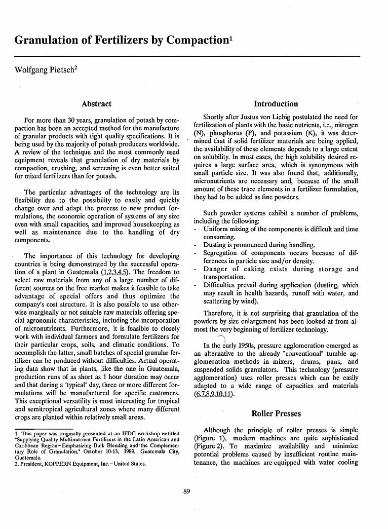
Granulation of Fertilizers by Compactionl
Wolfgang Pietsch2
Abstract
For more than 30 years, granulation of potash by compaction has been an accepted method for the manufactureof granular products with tight quality specifications. It isbeing used by the majority of potash producers worldwide.A review of the technique and the most commonly usedequipment reveals that granulation of dry materials bycompaction, crushing, and screening is even better suitedfor mixed fertilizers than for potash.
The particular advantages of the technology are itsflexibility due to the possibility to easily and quicklychange over and adapt the process to new product formulations, the economic operation of systems of any sizeeven with small capacities, and improved housekeeping aswell as maintenance due to the handling of drycomponents..
The importance of this technology for developingcountries is being demonstrated by the successful operation of a plant in Guatemala (1,2,~,~,~). The freedom toselect raw materials from any of a large number of different sources on the free market makes it feasible to takeadvantage of special offers and thus optimize thecompany's cost structure. It is also possible to use otherwise marginally or not suitable raw materials offering special agronomic characteristics, including the incorporationof micronutrients. Furthermore, it is feasible to closelywork with individual farmers and formulate fertilizers fortheir particular crops, soils, and climatic conditions. Toaccomplish the latter, small batches of special granular fertilizer can be produced without difficulties. Actual operating data show that in plants, like the one in Guatemala,production runs of as short as 1 hour duration may occurand that during a "typical" day, three or more different formulations will be manufactured for specific customers.This exceptional versatility is most interesting for tropicaland semitropical agricultural zones where many differentcrops are planted within relatively small areas.
1. This paper was originally presented at an IFDC workshop entitled"Supplying Quality Multinutrient Fertilizers in the Latin American andCaribbean Region - Emphasizing Bulk Blending and ·the Complementary Role of Granulation," October 10-13, 1989, Guatemala City,Guatemala.2. President, KOPPERN Equipment, Inc. - United States.
89
Introduction
Shortly after Justus von Liebig postulated the need forfertilization of plants with the basic nutrients, Le., nitrogen(N), phosphorus (P), and potassium (K), it was determined that if solid fertilizer materials are being applied,the availability of these elements depends to a large extenton solubility. In most cases, the high solubility desired requires a large surface area, which is synonymous withsmall particle size. It was also found that, additionally,micronutrients are necessary and, because of the smallamount of these trace elements in a fertilizer formulation,
.they had to be added as fine powders.
Such powder systems exhibit a number of problems,including the following:
Uniform mixing of the components is difficult and timeconsuming.Dusting is pronounced during handling.Segregation of components occurs because of differences in particle size and/or density.Danger of caking exists during storage andtransportation.Difficulties prevail during application (dusting, whichmay result in health hazards, runoff with water, andscattering by wind).
T~erefore, it is not surprising that granulation of thepowders by size enlargement has been looked at from almost the very beginning of fertilizer technology.
~',
In the ~arly 1950s, pressure agglomeration emerged asan alternative to the already "conventional" tumble agglomeration methods in mixers, drums, pans, andsuspended solids granulators. This technology (pressureagglomeration) uses roller presses which can be easilyadapted to a wide range of capacities and materials(~,:Z,8,2,10,11).
Roller Presses
Although the principle of roller presses is simple(Figure 1), modern machines are quite sophisticated(Figure 2). To maximize availability and minimizepotential problems caused by insufficient routine maintenance, the machines are equipped with water cooling
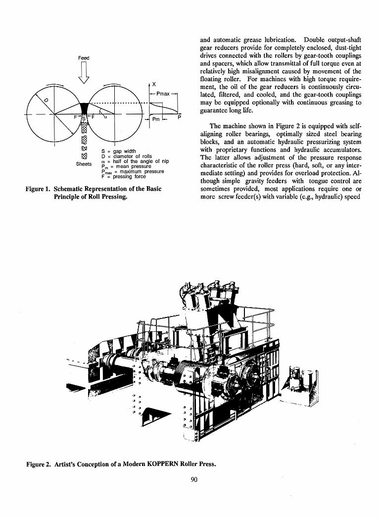
Figure 1. Schematic Representation of the BasicPrinciple of Roll Pressing.
Feed
~
Sheets
S = gap widthD = diameter of rollsa = half of the angle of nipPm = mean pressurePmax = maximum pressureF = pressing force
and automatic grease lubrication. Double output-shaftgear reducers provide for completely enclosed, dust-tightdrives connected with the rollers by gear-tooth couplingsand spacers, which allow transmittal of full torque even atrelatively high misalignment caused by movement of thefloating roller. For machines with high torque requirement, the oil of the gear reducers is continuously circulated, filtered, and cooled, and the gear-tooth couplingsmay be equipped optionally with continuous greasing toguarantee long life.
The machine shown in Figure 2 is equipped with selfaligning roller bearings, optimally sized steel bearingblocks, and an automatic hydraulic pressurizing systemwith proprietary functions and hydraulic accumulators.The latter allows adjustment of the pressure responsecharacteristic of the roller press (hard, soft, or any intermediate setting) and provides for overload protection. Although simple gravity feeders with tongue control aresometimes provided, most applications require one ormore screw feeder(s) with variable (e.g., hydraulic) speed
lWji.·.....:,~'I"'--. -.-.-. _..~
Figure 2. Artist's Conception of a Modern KOPPERN Roller Press.
90
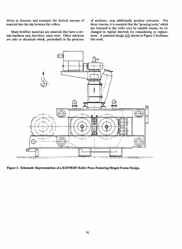
drives to deaerate and transport the desired amount ofmaterial into the nip between the rollers.
Many fertilizer materials are minerals that have a certain hardness and, therefore, cause wear. Other nutrientsare salts or chemicals which, particularly in the presence
!I
-~
of moisture, may additionally produce corrosion. Forthese reasons, it is essential that the "pressing tools," whichare fastened to the roller core by suitable means, be exchanged in regular intervals for remachining or replacement. A patented design (12) shown in Figure 3 facilitatesthis work.
Figure 3. Schematic Representation of a KOPPERN Roller Press Featuring Hinged Frame Design.
91
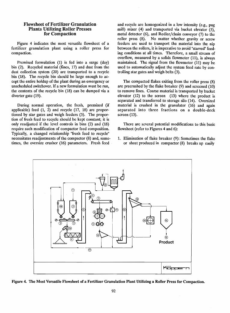
Flowsheet of Fertilizer GranulationPlants Utilizing Roller Presses
for Compaction
Figure 4 indicates the most versatile flowsheet of afertilizer granulation plant using a roller press forcompaction.
Premixed formulation (1) is fed into a surge (day)bin (2). Recycled material (fmes, 17) and dust from thedust collection system (20) are transported to a recyclebin (18). The recycle bin should be large enough to accept the entire holdup of the plant during an emergency orunscheduled switchover. If a new formulation must be run,the contents of the recycle bin (18) can be dumped via adiverter gate (19).
During normal operation, the fresh, premixed (ifapplicable) feed (1, 2) and recycle (17, 18) are proportioned by star gates and weigh feeders (3). The proportion of fresh feed to recycle should be kept constant; it isonly readjusted if the level controls in bins (2) and (18)require such modification of compactor feed composition.Typically, a changed relationship "fresh feed to recycle"necessitates readjustments of the compactor (8) and, sometimes, the oversize crusher (16) parameters. Fresh feed
and recycle are homogenized ·in a low intensity (e.g., pugmill) mixer (4) and transported via bucket elevator (5),metal detector (6), and Redler/chain conveyor (7) to theroller press (8). No matter whether gravity or screwfeeders are used to transport the material into the nipbetween the rollers, it is imperative to avoid "starved" feeding conditions at all times. Therefore, a small stream ofoverflow, measured by a solids flowmeter (11), is alwaysmaintained. The signal from the flowmeter (11) may beused to automatically adjust the system feed rate by controlling star gates and weigh belts (3).
The compacted flakes exiting from the roller press (8)are precrushed by the flake breaker (9) and screened (10)to remove fmes. Coarse material is transported by bucketelevator (12) to the screen (13) where the product isseparated and transferred to storage silo (14). Oversizedmaterial is crushed in the granulator (16) and againseparated into three fractions on a double-deckscreen (13).
There are several potential modifications to this basicflowsheet (refer to Figures 4 and 6):
1. Elimination of flake breaker (9): Sometimes the flakeor sheet produced in compactor (8) breaks up easily
@
Product
l1®(j)
@CD
®pb '
®
Figure 4. The Most Versatile Flowsheet of a Fertilizer Granulation Plant Utilizing a Roller Press for Compaction.
92
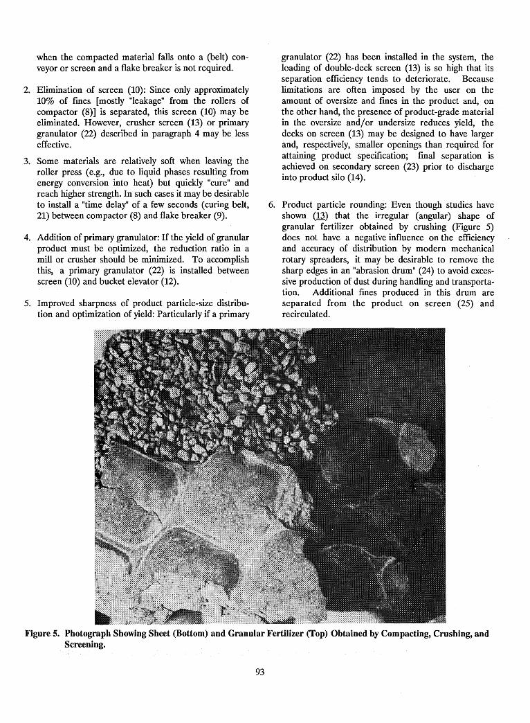
when the compacted material falls onto a (belt) conveyor or screen and a flake breaker is not required.
2. Elimination of screen (10): Since only approximately10% of fmes [mostly "leakage" from the rollers ofcompactor (8)] is separated, this screen (10) maybeeliminated. However, crusher screen (13) or primarygranulator (22) described in paragraph 4 may be lesseffective.
3. Some materials are relatively soft when leaving theroller press (e.g., due to liquid phases resulting fromenergy conversion into heat) but quickly "cure" andreach higher strength. In such cases it may be desirableto install a "time delay" of a few seconds (curing belt,21) between compactor (8) and flake breaker (9).
4. Addition of primary granulator: If the Yield of granularproduct must be optimized, the reduction ratio in amill or crusher should be minimized. To accomplishthis, a primary granulator (22) is installed betweenscreen (10) and bucket elevator (12).
5. Improved sharpness of product particle-size distribution and optimization of Yield: Particularly if a primary
granulator (22) has been installed in the system, theloading of double-deck screen (13) is so high that itsseparation efficiency tends to deteriorate. Becauselimitations are often imposed by the user on theamount of oversize and fmes in the product and, onthe other hand, the presence of product-grade materialin the oversize and/or undersize reduces Yield, thedecks on screen (13) may be designed to have largerand, respectively, smaller openings than required forattaining product specification; fmal separation isachieved on secondary screen (23) prior to dischargeinto product silo (14).
6. Product particle rounding: Even though studies haveshown (13) that the irregular (angular) shape ofgranular fertilizer obtained by crushing (Figure 5)does not have a negative influence on the efficiencyand accuracy of distribution by modern mechanicalrotary spreaders, it may be desirable to remove thesharp edges in an "abrasion drum" (24) to avoid excessive production of dust during handling and transportation. Additional fmes produced in this drum areseparated from the product on screen (25) andrecirculated.
Figure S. Photograph Showing Sheet (Bottom) and Granular Fertilizer (Top) Obtained by Compacting, Crushing, andScreening.
93
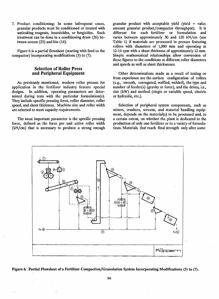
7. Product conditioning: In some infrequent cases,granular products must be conditioned or treated withanticaking reagents, insecticides, or fungicides. Suchtreatment can be done in a conditioning drum (26) between screen (25) and bin (14).
Figure 6 is a partial flowsheet (starting with feed to thecompactor) incorporating modifications (3) to (7).
Selection of Roller Pressand Peripheral Equipment
As previously mentioned, modern roller presses forapplication in the fertilizer industry feature specialdesigns. In addition, operating parameters are determined during tests with the particular formulation(s).They include specific pressing force, roller diameter, rollerspeed, and sheet thickness. Machine size and roller widthare selected to meet capacity requirements.
The most important parameter is the specific pressingforce, defmed as the force per unit active roller width(kN/cm) that is necessary to produce a strong enough
granular product with acceptable yield (yield = ratio:amount granular product/compactor throughput). It isdifferent for each fertilizer or formulation andvaries between approximately 30 and 120 kN/cm (seeTable 1) if materials are processed in presses featuringrollers with diameters of 1,000 .mm and operating at12-14 rpm with a sheet thickness of approximately 12 mm.Simple mathematical relationships allow conversion ofthese figures to the conditions at different roller diametersand speeds as well as sheet thicknesses.
Other determinations made as a result of testing orfrom experience are the surface configuration of rollers(e.g., smooth, corrugated, waffled, welded), the type andnumber of feeder(s) (gravity or force), and the drives, Le.,size (kW) and method (single or variable speed, electricor hydraulic, etc.).
Selection of peripheral system components, such asmixers, crushers, screens, and material handling equipment, depends on the material(s) to be processed and, toa certain extent, on whether the plant is dedicated to theproduction of only one fertilizer or to a variety of formulations. Materials that reach fmal strength only after some
®
To @ I--- ---L- --L.- ~ ___l
@ TO@
Figure 6~ Partial Flowsheet of a Fertilizer Compaction/Granulation System Incorporating Modifications (3) to (7).
94
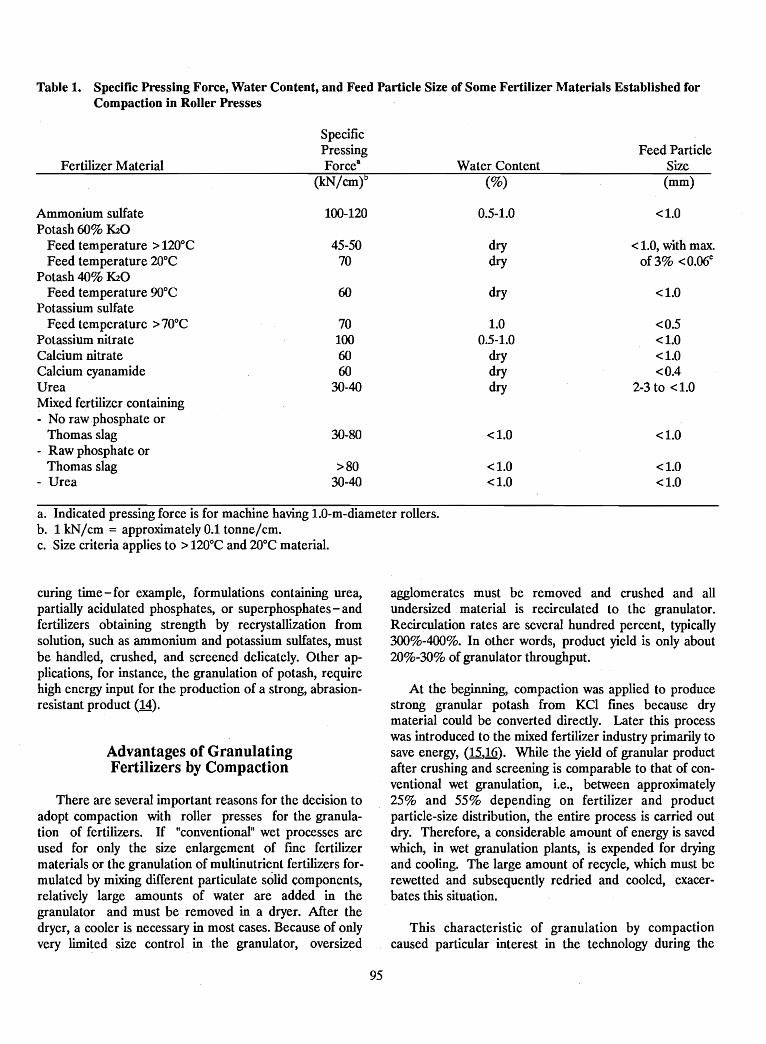
Table 1. Specific Pressing Force, Water Content, and Feed Particle Size of Some Fertilizer Materials Established forCompaction in Roller Presses
SpecificPressing Feed Particle
Fertilizer Material Forcea Water Content Size(kN/cm)b (%) (mm)
Ammonium sulfate 100-120 0.5-1.0 <1.0Potash 60% K20
Feed temperature> 120°C 45-50 dry <1.0, with max.Feed temperature 2Q°C 70 dry of 3% <O.06c
Potash 40% K20Feed temperature 90°C 60 dry <1.0
Potassium sulfateFeed temperature> 70°C 70 1.0 <0.5
Potassium nitrate 100 0.5-1.0 <1.0Calcium nitrate 60 dry <1.0Calcium cyanamide 60 dry <0.4Urea 30-40 dry 2-3 to <1.0Mixed fertilizer containing- No raw phosphate or
Thomas slag 30-80 <1.0 <1.0- Raw phosphate or
Thomas slag >80 <1.0 <1.0- Urea 30-40 <1.0 <1.0
a. Indicated pressing force is for machine having 1.0-m-diameter rollers.b. 1 kN/cm = approximately 0.1 tonne/cm.c. Size criteria applies to >120°C and 20°C material.
curing time-for example, formulations containing urea,partially acidulated phosphates, or superphosphates - andfertilizers obtaining strength by recrystallization fromsolution, such as ammonium and potassium sulfates, mustbe handled, crushed, and screened delicately. Other applications, for instance, the granulation of potash, requirehigh energy input for the production of a strong, abrasionresistant product (14).
Advantages of GranulatingFertilizers by Compaction
There are several important reasons for the decision toadopt compaction with roller presses for the granulation of fertilizers. If "conventional" wet processes areused for only the size enlargement of fme fertilizermaterials or the granulation of multinutrient fertilizers formulated by mixing different particulate solid components,relatively large amounts of water are added in thegranulator and must be removed in a dryer. After thedryer, a cooler is necessary in most cases. Because of onlyvery limited size control in the granulator, oversized
95
agglomerates must be removed and crushed and allundersized material is recirculated to the granulator.Recirculation rates are several hundred percent, typically300%-400%. In other words, product yield is only about20%-30% of granulator throughput.
At the beginning, compaction was applied to producestrong granular potash from KCI fmes because drymaterial could be converted directly. Later this processwas introduced to the mixed fertilizer industry primarily tosave energy, (15,16). While the yield of granular productafter crushing and screening is comparable to that of conventional wet granulation, Le., between approximately25% and 55% depending on fertilizer and productparticle-size distribution, the entire process is carried outdry. Therefore, a considerable amount of energy is savedwhich, in wet granulation plants, is expended for dryingand cooling. The large amount of recycle, which must berewetted and subsequently redried and cooled, exacerbates this situation.
This characteristic of granulation by compactioncaused particular interest in the technology during the
"world energy crisis" when energy prices rose to· unprecedented heights. Today, it depends on the specific locationand local costs of energy whether this feature is still adeciding factor. In the meantime, other advantages oftenplaya more important role (1,~,J,1,5:,2).
Closely related to the above is the combination ofgranulation by compaction with conventional wet granulation whereby all or most of the fmes and the oversized particles are compacted. The original oversize crusher mayhave to be upgraded in this case to handle the compactedsheet, but the screening capacity is normally sufficient.The product is a mixture of nearly spherical and irregularly formed particles. This measure increases thecapacity of the original system and, at the same tune,considerably reduces energy consumption per tonne ofgranular product.
Today's most important advantage of granulation bycompaction is the extreme versatility of the system:
1. Literally all dry particulate materials with only a fewlimitations as to maximum amounts in a formulation(e.g., urea or triple superphosphate) can be processed.This also includes such materials as, for example, dry,digested sludge from municipal waste treatment plants(17,18).
2. To minimize cost, raw materials can be purchased onthe world market without specific requirements on particle size. Off-specification products (fines) can beused and often are even preferable.
3. Compaction plants can be designed for economicoperation at any feed rate. Production capacities perline are feasible between 0.1 and 50 tph.
4. Larger plants are preferably equipped with two ormore lines, fed by one large compounding (batching orformulation) system. Otherwise the lines are keptseparate to improve availability because only one lineis down during maintenance and emergencyshutdowns.
5. If a plant equipped with multiple lines featuresseparate day bins for· fresh feed, recirculating fmes,and granulated product, each line can be operated ondifferent formulations.
6. Production of· small batches is feasible. Depending onthe necessary amount of cleaning during changeover(determined by how much cross-contamination can betolerated), up to three different batches(formulations)per 8-h shift can be produced.
96
7. Granulation·. plants' utilizing compaction can. be combined with either custom designed batching systems orwith standardized formulation or bulk-blending units.Particularly the latter methods allow easy expansion ofbulk blending to mixed fertilizer granulation.
8. Any compaction/granulation system can be utilized asa regional production facility for the manufacturing ofbulk-blend-grade material from off-specification feeds.These include special formulations required by thelocal market such as indigenous flilers, with of.withoutmajor nutrients, or carriers. for micronutrients. Suchproducts can then be used together with importedbulk-blend grade materials in bulk-blending plants.
9. Finally, the fact should be mentioned that plants withroller presses can be easily adapted to the manufacturing of urea supergranules for deep placement in wetland rice production (19). In this case, the rollersurface must be modified, the flake breaker (9 inFigure 4) bypassed, and the granulator (16 in Figure 4)blocked off.
Present Status of Granulationof Fertilizers by Compaction
Although the history of. fertilizer granulation is relatively short, a large number of plants are operatingthroughout the world and knowledge about granulated fertilizersas well as their manufacturing· methods is welldisseminated.
The granulation of fertilizers by compaction is muchless known than the "conventional" chemical, wet, or meltgranulation techniques. Roller presses for the compactionof potash were rust introduced in the 1950s. Today, nearlyall major potash producers use this technology for themanufacturing of granular and coarse grades (20). Approximately 10 years after the rust use of roller presses forpotash granulation, this equipment began also to be usedfor other fertilizer materials. Today, the technology is wellestablished, and many plants are operating throughout theworld (20).
Summary
Today's intensive farming and the needs for increasedcrop (food) production in the developing countries
demand the use of fertilizers. To improve application tothe fields and the quality of mixed fertilizers, several techniques have been developed to produce uniform, dustfree,nonsegregating, granular products from particulate (fineand dusty) fertilizer components.
Because, in contrast to conventional methods, thegranulation of fertilizers by compaction uses dry feedmaterials from an almost unlimited number of sourcesand without special requirements on particle size or distribution, this technique is gaining increasing importancein the industry.
A number of special characteristics, which includeversatility as well as applicability for small capacities andbatches, make the technology of particular importance fordeveloping countries.
References
1. Rodriguez, C. M. 1989. Production of NPKs andother fertilizers by the method of compaction. Aviable solution for developing countries. Proc. Int.Conf. Fertilizer Latin America. Brit. Sulphur Corp.,London, United Kingdom, Caracas, Venezuela,449-458.
2. Pietsch, W., and C. M. Rodriguez. 1987. Granulationof Fertilizers by Compaction. Proc. 20th BiennialConf. IBA. Editor: D. L. Roth, Orlando, FL, 113-126.
3. Swisher, M. A., and C. M. Rodriguez. 1988. Compaction of NPK Fertilizers, Proc. 38th Annual Fert. Ind.Round Table, Baltimore, MD, 34-37.
4. Taylor, L. 1988. Establishing a NPK Compaction/Granulation Plant in Guatemala, Proc. Int.Workshop, IFDC Spec. Publ. SP-9, Madras, India,57-58.
5. Rodriguez, C. M. 1988. Compaction of NPKs inGuatemala, Proc. Int. Workshop, IFDC Spec. Publ.SP-9, Madras, India, 59-71.
·6. Pietsch, W. 1971. Das Kornen von Diingemitteln mitdem Kompaktier-Granulierverfahren. AufbereitungsTechnik 12, Vol. 12, No. 11, 684-690. English versionin: Proc. of "Particle Technology," Seminar, IndianInstitute of Technology, Madras, 335-348.
7. Stahl, H. 1980. Kompaktierung von Diingemitteln,Stand der Technik/Compacting of fertilizers, current
97
state of technology (bilingual), AufbereitungsTechnik, Vol. 21, No. 10, 525-533.
8. Lupin, M. S., and N. D. Le. 1983. CompactionAlternative Approach for Granular Fertilizers, Tech;Bulletin IFDC T-25.
9. Pietsch, W. 1984. Granulation of Mixed Fertilizers byCompaction, Proc. 34th Annual Fert. Ind. RoundTable, Baltimore, MD, 48-58.
10. Zisselmar, R. 1987. Kompaktiergranulieren mitWalzenpressen, Chern. Ing. Tech., Vol. 59, No. 10,779-787.
11. Zisselmar, R. 1988. Compaction/Granulation ofFertilizers, Proc. Int. Workshop, IFDC Spec. Publ.SP-9, Madras, India, 46-56.
12. Koch, F. and W. Siepermann. 1975. Roll Press, U.S.Patent No. 3,899,965.
13. Briibach, M. 1973. The influence of particle size,strength, and friction on the distribution of granularfertilizers and insecticides, Ph.D. Thesis, Tech. Univ.,West Berlin.
14. Pietsch, W. 1983. Modern Equipment and Plants forPotash Granulation, Proc. 1st Int. Potash TechnologyConf., Saskatoon, Saskatchewan, 661-669.
15. Pietsch, W. 1983. Energy Conservation in theFertilizer Industry - The Compaction/Granulation
Process for Mixed (NPK) Fertilizers, Proc. 18th Biennial Conf., IBA, Colorado Springs, CO, 243-265.
16. Pietsch, W. 1983. Low-Energy Production ofGranular NPK Fertilizers by CompactionGranulation, Proc. Int. Conf. Fertilizer, London,United Kingdom, Vol. 2, 467-479.
17. Pietsch, W. 1985. Compaction/Granulation of Dry,Digested Sludge from Municipal Waste TreatmentPlants, Proc. 19th Biennial Conf., IBA, Baltimore,MD, 179-194.
18. Schafer, P. et al. 1987. Compaction and Granulationof Dried Sludge at Ocean County, NJ, 60th AnnualConf. WPCF, Philadelphia, PA.
19. Lupin, M. S. et al. 1983. Briquetting - AlternativeProcess for Urea Supergranules, Tech. BulletinIFDCT-26.
20. Pietsch, W. 1989. History, Application, and PresentStatus of Mixed Fertilizer Granulation by Compaction, Proc. Int. Conf. Fertilizer Latin America, Brit.Sulphur Corp., London, UK, Caracas, Venezuela,153-173.
98
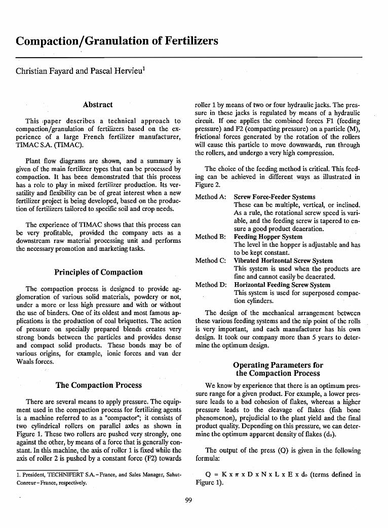
Compaction/Granulation of Fertilizers
Christian Fayard and Pascal Hervieu1
Abstract
This ;paper describes a technical approach tocompaction/granulation of fertilizers based on the experience of a large French fertilizer manufacturer,TIMAC SA. (TIMAC).
Plant flow diagrams are shown, and a summary isgiven of the main fertilizer types that can be processed bycompaction. It has been demonstrated that this processhas a role to play in mixed fertilizer production. Its versatility and flexibility can be of great interest when a newfertilizer project is being developed, based on the production of fertilizers tailored to specific soil and crop needs.
The experience of TIMAC shows that this process canbe very profitable, provided the company acts as adownstream raw material processing unit and performsthe necessary promotion and marketing tasks.
Principles of Compaction
The compaction process is designed to provide agglomeration of various solid materials, powdery or not,under a more or less high pressure and with or withoutthe use of binders. One of its oldest and most famous applications is the production of coal briquettes. The actionof pressure on specially prepared blends creates verystrong bonds between the particles and provides denseand compact solid products. These bonds may be ofvarious origins, for example, ionic forces and van derWaals forces.
The Compaction Process
There are several means to apply pressure. The equipment used in the compaction process for fertilizing agentsis a machine referred to as a "compactor"; it consists oftwo cylindrical rollers on parallel axles as shown inFigure 1. These two rollers are pushed very strongly, oneagainst the other, by means of a force that is generally constant. In this machine, the axis of roller 1 is fixed while theaxis of roller 2 is pushed by a constant force (F2) towards
1. President, TECHNIFERT SA. - France, and Sales Manager, Sahut
Conreur- France, respectively.
99
roller 1 by means of two or four hydraulic jacks. The pressure in these jacks is regulated by means of a hydrauliccircuit. If one· applies the combined forces F1 (feedingpressure) and F2 (compacting pressure) on a particle (M),frictional forces generated by the rotation of the rollerswill cause this particle to move downwards, run throughthe rollers, and undergo a very high compression.
The choice of the feeding method is critical. This feeding can be achieved in different ways as illustrated inFigure 2.
Method A: Screw Force-Feeder SystemsThese can be multiple, vertical, or inclined.As a rule, the rotational screw speed is variable, and the feeding screw is tapered to ensure a good product deaeration.
Method B: Feeding Hopper SystemThe level in the hopper is adjustable and hasto be kept constant.
Method C: Vibrated Horizontal Screw SystemThis system is used when the products arefme and cannot easily be deaerated.
Method D: Horizontal Feeding Screw SystemThis system is used for superposed compaction cylinders.
The design of the mechanical arrangement betweenthese various feeding systems and the nip point of the rollsis very important, and each manufacturer has his owndesign. It took our company more than 5 years to determine the optimum design.
Operating Parameters forthe Compaction Process
We know by experience that there is an optimum pressure range for a given product. For example, a lower pressure .leads to a bad cohesion of flakes, whereas a higherpressure leads to the cleavage of flakes (fish bonephenomenon), prejudicial to the plant yield and the finalproduct quality. Depending on this pressure, we can determine the optimum apparent density of flakes (do).
The output of the press (0) is given in the followingformula:
o = K x 7[' x D x N x L x E x do (terms defined inFigure 1).
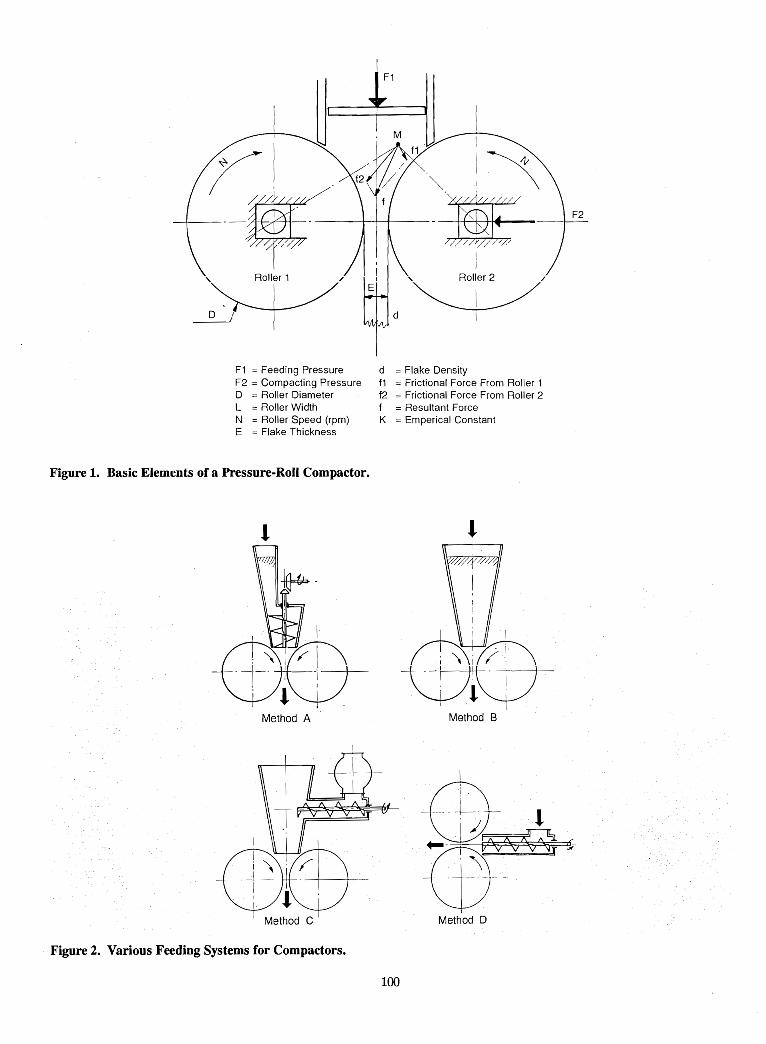
" Roller 1
D
F1 == Feeding PressureF2 == Compacting PressureD == Roller DiameterL = Roller WidthN = Roller Speed (rpm)E =Flake Thickness
Figure 1. Basic Elements of a Pressure-Roll Compactor.
Method A
d = Flake Densityf1 =Frictional Force From Roller 1f2 == Frictional Force From Roller 2f = Resultant ForceK =Emperical Constant
Method B
Method C
Figure 2. Various Feeding Systems for Compactors.
I
..~~ijj__ J
Mettwd D
100
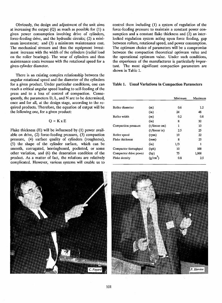
Obviously, the design and adjustment of the unit aimsat increasing the output (0) as much as possible for (1) agiven power consumption involving drive of cylinders,force-feeding drive, and the hydraulic circuits; (2) a minimum investment; and (3) a minimum maintenance cost.The mechanical stresses and thus the equipment investment increase with the width of the cylinders (radial loadon the roller bearings). The wear of cylinders and thusmaintenance costs increase with the rotational speed for agiven cylinder diameter.
control them including (1) a system of regulation of theforce-feeding pressure to maintain a constant power consumption and a constant flake thickness and (2) an interlocked regulation system acting upon force feeding, gapbetween rollers, rotational speed, and power consumption.The optimum choice of parameters will be a compromisebetween the compaction theoretical optimum value andthe operational optimum value. Under such conditions,the experience of the manufacturer is particularly important. The most significant compaction parameters areshown in Table 1. .
Table 1. Usual Variations in Compaction Parameters
Roller diameter (m) 0.6 1.2
(in) 24 48
Roller width (m) 0.2 0.8
(in) 8 32
Compaction pressure (t/linear cm) 1 10
(t/linear in) 2.5 25
Roller speed (rpm) 10 22
Flake thickness (mm) 8 25
(in) 1/3 1
Compactor throughput (tph) 10 100
Compactor drive power (hp) 75 1,000
Flake density (g/cm3
) 0.8 2.5
There is an existing complex relationship between theangular rotational speed and the diameter of the cylindersfor a given product. Under particular conditions, one canreach a critical angular speed leading to self-feeding of thepress and to a loss of control of compaction. Consequently, the parameters D, L, and N are to be determined,once and for all, at the design stage, according to the required products. Therefore, the equation of output will bethe following one, for a given product:
0= KxE
Flake thickness (E) will be influenced by (1) power available on drive, (2) force-feeding pressure, (3) compactionpressure, (4) surface quality of cylinders (roughness),(5) the shape of the cylinder surface, which can besmooth, corrugated, herringboned, pocketed, or someother variation, and (6) the deaeration condition of· theproduct. As a matter of fact, the relations are relativelycomplicated. However, various systems will enable us to
Minimum Maximum
101
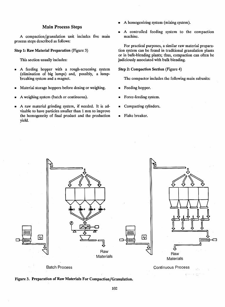
• A homogenizing system (mixing system).Main Process Steps
A compaction/granulation unit includes five mainprocess steps described as follows:
Step 1: Raw Material Preparation (Figure 3)
This section usually includes:
• A controlled feeding system to the compactionmachine.
For practical purposes, a similar raw material preparation system can be found in traditional granulation plantsor in bulk-blending plants; thus, compaction can often bejudiciously associated with bulk blending.
• A feeding hopper with a rough-screening system(elimination of big lumps) and, possibly, a lumpbreaking system and a magnet.
Step 2: Compaction Section (Figure 4)
The compactor includes the following main subunits:
• Material storage hoppers before dosing or weighing. • Feeding hopper.
• A weighing system (batch or continuous). • Force-feeding system.
• A raw material grinding system, if needed. It is advisable to have particles smaller than 1 mm to improvethe homogeneity of final product and the productionyield.
• Compacting cylinders.
• Flake breaker.
JJRaw
Materials
Raw. Materials
Batch Process Continuous Process
Figure 3. Preparation of Raw Materials For Compaction/Granulation.
102
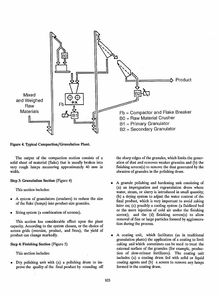
=====~ Product
t
~~
@~
~I~ompactor and Flake Breaker
80 = Raw Material Crusher81 = Primary Granulator82 = Secondary Granulator
Mixedand Weighed
RawMaterials
Figure 4. Typical Compaction/Granulation Plant.
The output of the compaction section consists of asolid sheet of material (flake) that is usually broken intovery rough lumps measuring approximately 40 mm inwidth.
the sharp edges of the granules, which limits the generation of dust and removes weaker granules and (b) thefmishing screen(s) to remove the dust generated by theabrasion of granules in the polishing drum.
Step 3: Granulation Section (Figure 4)
This section includes:
• A system of granulators (crushers) to reduce the sizeof the flake (lumps) into product-size granules.
• Sizing system (a combination of screens).
This section has considerable effect upon the plantcapacity. According to the system chosen, or the choice ofscreen grids (oversize, product, and fmes) , the yield ofproduct can change markedly.
Step 4: Finishing Section (Figure 5)
This section includes:
• Dry polishing unit with (a) a polishing drum to improve the quality of the final product by rounding off
• A granule polishing and hardening unit consisting of(a) an impregnation and regranulation drum wherewater, steam, or slurry is introduced in small quantity;(b) a drying system to adjust the water content of thefmal product, which is very important to avoid cakinglater on; (c) possibly a cooling system (a fluidized bedor the mere injection of cold air under the finishingscreen); and the (d) finishing screen(s) to allowremoval of fine or large particles formed by agglomeration during the process.
• A coating unit, which facilitates (as in traditionalgranulation plants) the application of a coating to limitcaking and which sometimes can be used to treat theexternal surface of the granules (for example, production of slow-release fertilizers). The coating unitincludes (a) a coating drum fed with solid or liquidcoating agents and (b) a screen to remove any lumpsformed in the coating drum.
103
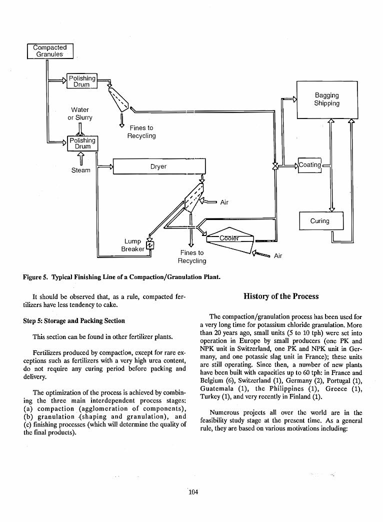
CompactedGranules
BaggingShipping
Air
Wateror Slurry
Figure 5. Typical Finishing Line of a Compaction/Granulation Plant.
It should be observed that, as a rule, compacted fertilizers have less tendency to cake.
History of the Process
Step 5: Storage and Packing Section
This section can be found in other fertilizer plants.
Fertilizers produced by compaction, except for rare exceptions such as fertilizers with a very high urea content,do not require any curing period before packing anddelivery.
The optimization of the process is achieved by combining the three main interdependent. process stages:(a) compact~on (agglomeration of components),(b) granulatIon (shaping and granulation), and(c) finishing processes (which will determine the quality ofthe final products).
The compaction/granulation process has been used fora very long time for potassium chloride granulation. Morethan 2? ye~s ago, small units (5 to 10 tph) were set intooperatIon m Europe by small producers (one PK andNPK unit in Switzerland, one PK and NPK unit in Germany, and one potassic slag unit in France); these unitsare still operating. Since then, a number of new plantshave been built with capacities up to 60 tph: in France andBelgium (6), Switzerland (1), Germany (2), Portugal (1),Guatemala (1), the Philippines (1), Greece (1),Turkey (1), and very recently in Finland (1).
Numerous projects all over the world are in thefeasibility study stage at the present time. As a generalrule, they are based on various motivations including:
104
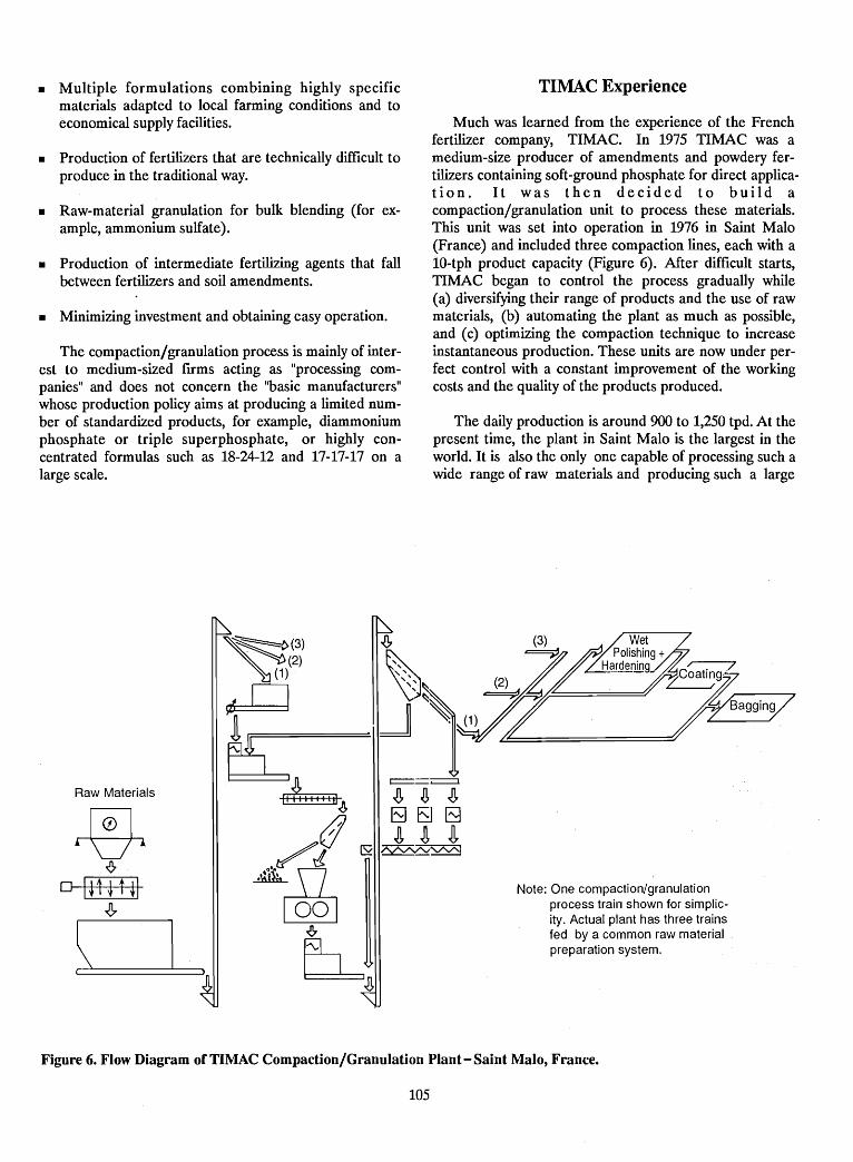
• Multiple formulations combining highly specificmaterials adapted to local farming conditions and toeconomical supply facilities.
• Production of fertilizers that are technically difficult toproduce in the traditional way.
• Raw-material granulation for bulk blending (for example, ammonium sulfate).
• Production of intermediate fertilizing agents that fallbetween fertilizers and soil amendments.
• Minimizing investment and obtaining easy operation.
The compaction/granulation process is mainly of interest to medium-sized firms acting as "processing companies" and does not concern the "basic manufacturers"whose production policy aims at producing a limited number of standardized products, for example, diammoniumphosphate or triple superphosphate, or highly concentrated formulas such as 18-24-12 and 17-17-17 on alarge scale.
TlMAC Experience
Much was learned from the experience of the Frenchfertilizer company, TIMAC. In 1975 TIMAC was amedium-size producer of amendments and powdery fertilizers containing soft-ground phosphate for direct application. It was then decided to build acompaction/granulation unit to process these materials.This unit was set into operation in 1976 in Saint Malo(France) and included three compaction lines, each with a10-tph product capacity (Figure 6). After difficult starts,TIMAC began to control the process gradually while(a) diversifying their range of products and the use of rawmaterials, (b) automating the plant as much as possible,and (c) optimizing the compaction technique to increaseinstantaneous production. These units are now under perfect control with a constant improvement of the workingcosts and the quality of the products produced.
The daily production is around 900 to 1,250 tpd. At thepresent time, the plant in Saint Malo is the largest in theworld. It is also the only one capable of processing such awide range of raw materials and producing such a large
Note: One compaction/granulationprocess train shown for simplicity. Actual plant has three trainsfed by a common raw materialpreparation system.
Raw Materials
\ LFigure 6. Flow Diagram of TlMAC Compaction/Granulation Plant - Saint Malo, France.
105
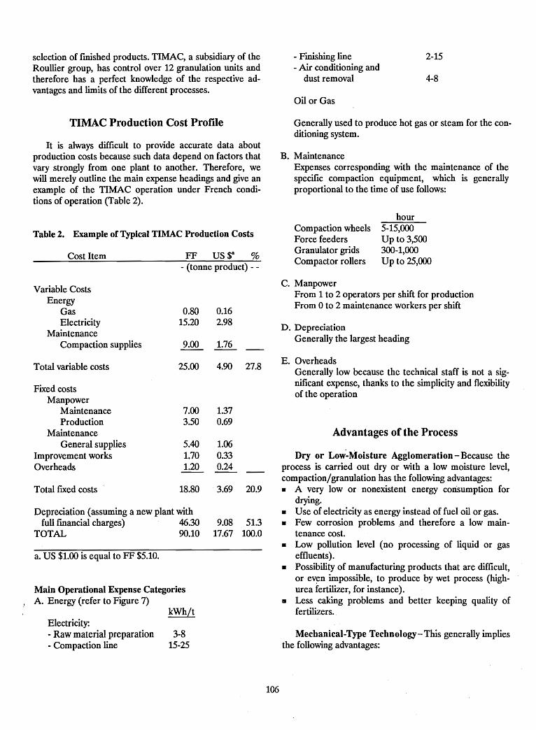
selection of finished products. TlMAC, a subsidiary of theRoullier group, has control over 12 granulation units andtherefore has a perfect knowledge of the respective advantages and limits of the different processes.
- Finishing line- Air conditioning and
dust removal
Oil or Gas
2-15
4-8
TlMAC Production Cost Profile
It is always difficult to provide accurate data aboutproduction costs because such data depend on factors thatvary strongly from one plant to another. Therefore, wewill merely outline the main expense headings and give anexample of the TIMAC operation under French conditions of operation (Table 2).
Generally used to produce hot gas or steam for the conditioning system.
B. MaintenanceExpenses corresponding with the maintenance of thespecific compaction equipment, which is generallyproportional to the time of use follows:
hour
Table 2. Example of Typical TlMAC Production Costs
Cost Item FF US $8 %- (tonne product) - -
Compaction wheelsForce feedersGranulator gridsCompactor rollers
5-15,000Up to 3,500300-1,000Up to 25,000
Variable CostsEnergy
GasElectricity
MaintenanceCompaction supplies
0.8015.20
9.00
0.162.98
1.76
C. ManpowerFrom 1 to 2 operators per shift for productionFrom 0 to 2 maintenance workers per shift
D. DepreciationGenerally the largest heading
a. US $1.00 is equal to FF $5.10.
Main Operational Expense CategoriesA. Energy (refer to Figure 7)
Depreciation (assuming a new plant withfull fmandal charges) 46.30
TOTAL 90.10
7.00 1.373.50 0.69
5.40 1.061.70 0.331.20 0.24
18.80 3.69 20.9
Advantages of the Process
Mechanical-Type Technology-This generally impliesthe following advantages:
E. OverheadsGenerally low because the technical staff is not a significant expense, thanks to the simplicity and flexibilityof the operation
Dry or Low"-Moisture Agglomeration - Because theprocess is carried out dry or with a low moisture level,compaction/granulation has the following advantages:• A very low or nonexistent energy consumption for
drying.• Use of electricity as energy instead of fuel oil or gas.• Few corrosion problems ,and therefore a low main
tenance cost.• Low pollution level (no processing of liquid or gas
effluents) .• Possibility of manufacturing products that are difficult,
or ev~n impossible, to produce by wet process (highurea fertilizer, for instance).
• Less caking problems and better keeping quality offertilizers..
4.90 27.8
9.08 51.317.67 100.0
25.00
kWh/t
3-815-25
Electricity:- Raw material preparation- Compaction line
Fixed costsManpower
MaintenanceProduction
MaintenanceGeneral supplies
Improvement worksOverheads
Total variable costs
Total fixed costs
106
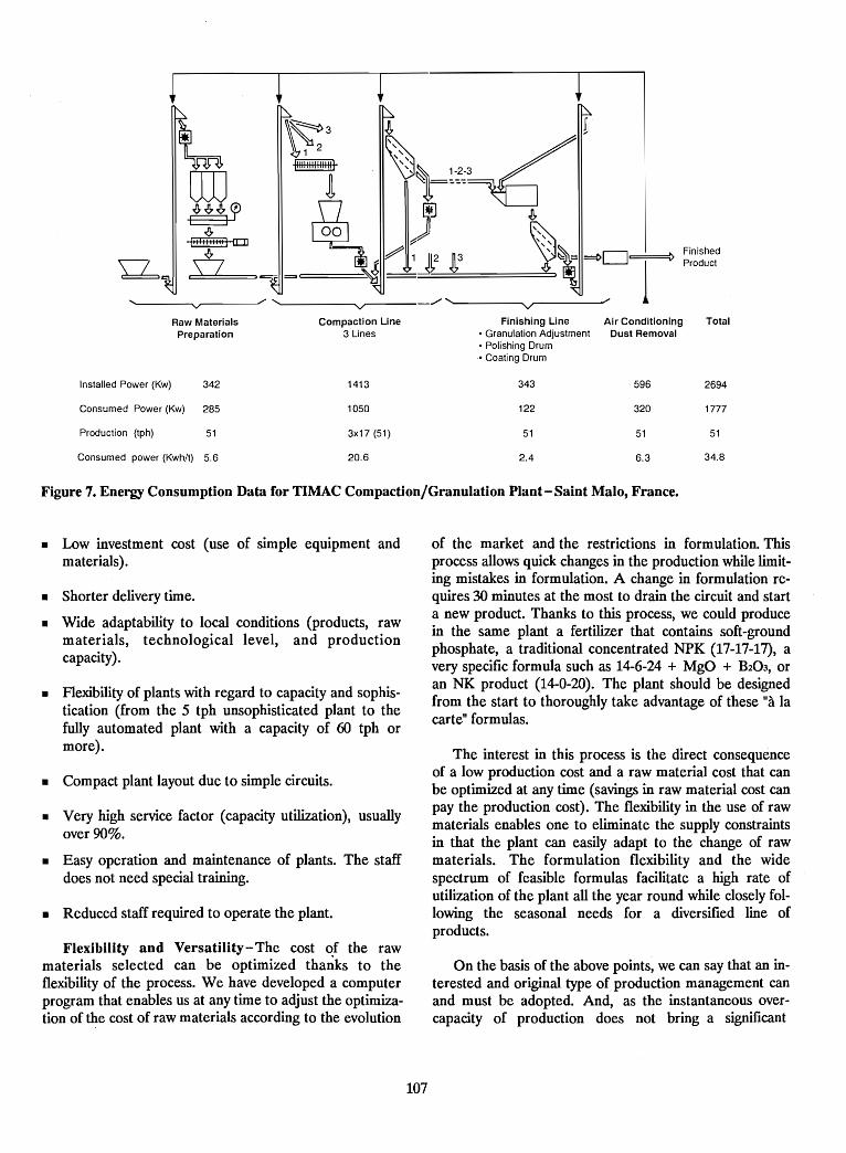
Finishing Line Air Conditioning Total• Granulation Adjustment Dust Removal• Polishing Drum• Coating Drum
343 596 2694
122 320 1777
51 51 51
2.4 6.3 34.8
FinishedProduct
V/,
V./'
Raw Materials Compaction LinePreparation 3 Lines
Installed Power (Kw) 342 1413
Consumed Power (Kw) 285 1050
Production (tph) 51 3x17 (51)
Consumed power (Kwh/t) 5.6 20.6
Figure 7. Energy Consumption Data for TIMAC Compaction/Granulation Plant-Saint Malo, France.
• Low investment cost (use of simple equipment andmaterials) .
• Shorter delivery time.
• Wide adaptability to local conditions (products, rawmaterials, technological level, and productioncapacity).
• Flexibility of plants with regard to capacity and sophistication (from the 5 tph unsophisticated plant to thefully automated plant with a capacity of 60 tph ormore).
• Compact plant layout due to simple circuits.
• Very high service factor (capacity utilization), usuallyover 90%.
• Easy operation and maintenance of plants. The staffdoes not need special training.
• Reduced staff required to operate the plant.
Flexibility and Versatility-The cost of the rawmaterials selected can be optimized tha~ks to theflexibility of the process. We have developed a computerprogram that enables us at any time to adjust the optimization of the cost of raw materials according to the evolution
of the market and the restrictions in formulation. Thisprocess allows quick changes in the production while limiting mistakes in formulation. A change in formulation requires 30 minutes at the most to drain the circuit and starta new product. Thanks to this process, we could producein the same plant a fertilizer that contains soft-groundphosphate, a traditional concentrated NPK (17-17-17), avery specific formula such as 14-6-24 + MgO + B203, oran NK product (14-0-20). The plant should be designedfrom the start to thoroughly take advantage of these "a lacarte" formulas.
The interest in this process is the direct consequenceof a low production cost and a raw material cost that canbe optimized at any time (savings in raw material cost canpay the production cost). The flexibility in the use of rawmaterials enables one to eliminate the supply constraintsin that the plant can easily adapt to the change of rawmaterials. The formulation flexibility and the widespectrum of feasible formulas facilitate a high rate ofutilization of the plant all the year round while closely following the seasonal needs for a diversified line ofproducts.
On the basis of the above points, we can say that an interested and original type of production management canand must be adopted. And, as the instantaneous overcapacity of production does not bring a significant
107
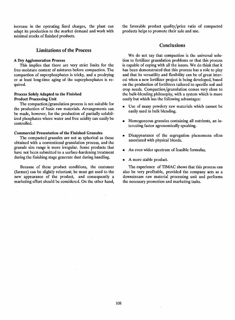
increase in the operating fIxed charges, the plant canadapt its production to the market demand and work withminimal stocks of fInished products.
Limitations of the Process
A Dry Agglomeration ProcessThis implies that there are very strict limits for the
free-moisture content of mixtures before compaction. Thecompaction of superphosphates is tricky, and a predryingor at least long-time aging of the superphosphates is required.
Process Solely Adapted to the FinishedProduct Processing Unit
The compaction/granulation process is not suitable forthe production of basic raw materials. Arrangements canbe made, however, for the production of partially solubilized phosphates where water and free acidity can easily becontrolled.
Commercial Presentation of the Finished GranulesThe compacted granules are not as spherical as those
obtained with a conventional granulation process, and thegranule size range is more irregular. Some products thathave not been submitted to a surface-hardening treatmentduring the fInishing stage generate dust during handling.
Because of these product conditions, the customer(farmer) can be slightly reluctant; he must get used to thenew appearance of the product, and consequently amarketing effort should be considered. On the other hand,
108
the favorable product quality/price ratio of compactedproducts helps to promote their sale and use.
Conclusions
We do not say that compaction is the universal solution to fertilizer granulation problems or that this processis capable of coping with all the issues. We do think that ithas been demonstrated that this process has a role to playand that its versatility and flexibility can be of great interest when a new fertilizer project is being developed, basedon the production of fertilizers tailored to specifIc soil andcrop needs. Compaction/granulation comes very close tothe bulk-blending philosophy, with a system which is morecostly but which has the following advantages:
• Use of many powdery raw materials which cannot beeasily used in bulk blending.
• Homogeneous granules containing all nutrients, an interesting factor agronomically speaking.
• Disappearance of the segregation phenomena oftenassociated with physical blends.
• An even wider spectrum of feasible formulas.
• A more stable product.
The experience of TIMAC shows that this process canalso be very profItable, provided the company acts as adownstream raw material processing unit and performsthe necessary promotion and marketing tasks.
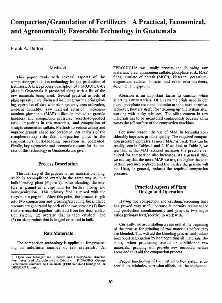
Compaction/Granulation of Fertilizers - A Practical, Economical,and" Agronomically Favorable Technology in Guatemala
Frank A. Dalton1
Abstract
This paper deals with several aspects of thecompaction/granulation technology for the production offertilizers. A brief process description of FERQUIGUA'splant in Guatemala is presented along with a list of theraw materials being used. Several practical aspects ofplant operation are discussed including raw material grinding, operation of dust collection systems, urea utilization,ambient humidity, raw material abrasion, monoammonium phosphate (MAP) utilization related to granulehardness and compaction pressure, recycle-to-productratio, impurities in raw materials, and compaction ofstraight ammonium sulfate. Methods to reduce caking andimprove granule shape are presented. An analysis of thecomplementary role that compaction plays in thecorporation's bulk-blending operation is presented.Finally, key agronomic and economic reasons for the success of this technology in Guatemala are given.
Process Description
The fIrst step of the process is raw material blending,which is accomplished exactly in the same way as in abulk-blending plant (Figure 1). After blending, the mixture is ground in a cage mill for further mixing andhomogenization. This primary feed is mixed with therecycle in a pug mill. After this point, the process is splitinto two compaction and crushing/screening lines. Threestreams are generated by each of the two screens: (1) fmesthat are recycled together with dust from the dust collection system, (2) oversize that is then crushed, and(3) on-size product that is bagged or stored in bulk.
Raw Materials
The compaction technology is applicable for processing an indefinite number of raw materials. At
1. Operations Manager and Research and Development Director,Fertilizers and Agrochemicals Division, DISAGRO Group.Fcrtilizantcs Quimicos de Guatemala (FERQUIGUA) belongs to theDlSAGRO Group.
109
FERQUIGUA we usually process the following rawmaterials: urea, ammonium sulfate, phosphate rock, MAPfmes, muriate of potash (MOP), kieserite, potassiummagnesium sulfate, borates and other micronutrients,dolomite, and gypsum.
Abrasion is an important factor to consider whenselecting raw materials. Of all raw materials used in ourplant, phosphate rock and dolomite are the most abrasive.However, they are useful for "cleaning up" the system afterworking with sticky mixtures. The silica content in rawmaterials has to be monitored continuously because silicawears the roll surface of the compaction machines.
For some reason, the use of MAP in formulas considerably improves product quality. The required compaction pressure increases as more MAP is used. This can bereadily seen in Tables 1 and 2. If we look at Table 2, wesee that as the MAP content increases the pressure required for compaction also increases. As a general rule,we can say that the more MAP we use, the higher the compaction pressure required and the harder the granule willbe. Urea, in general, reduces the required compactionpressure.
Practical Aspects of PlantDesign and Operation
Having two compaction and crushing/screening lineshas proved very useful because it permits maintenanceand production simultaneously and provides two majorratios (primary feed/recycle) to work with.
Currently, we are installing a cage mill at the beginningof the process for grinding of raw materials before theyare blended. This will aid the blending process and reducein-process segregation by homogenizing all materials. Besides, when processing coated or conditioned rawmaterials, grinding will provide new uncoated surfaceareas and thus aid the compaction process.
Proper functioning of the dust collection system is essential to minimize corrosion effects on the equipment.
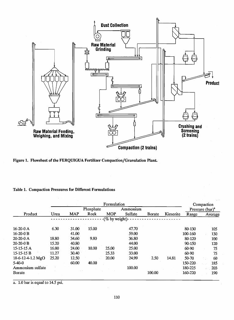
Product
Crushing andScreening(2 trains)
Raw Material Feeding,Weighing, and Mixing
Figure 1. Flowsheet of the FERQUIGUA Fertilizer Compaction/Granulation Plant.
Table 1. Compaction Pressures for Different Formulations
Product
FormulationPhosphate Ammonium
Urea MAP Rock MOP Sulfate Borate Kieserite- - - - - - - - - - - - - - - - - - - - - -(% by weight)- - - - - - - - - - - - - - - - - - - - - -
CompactionPressure (bart
Range Average
16-20-0 A 6.30 31.00 15.00 47.70 80-130 10516-20-0B 41.00 59.00 100-160 13020-20-0 A 18.80 34.60 9.80 36.80 80-120 10020-20-0 B 15.20 40.80 44.00 90-150 12015-15-15 A 16.00 24.00 10.00 25.00 25.00 60-90 7515~15-15 B 11.27 30.40 25.33 33.00 60-90 7518-6-12-4-1.2 MgO 25.20 12.50 20.00 24.99 2.50 14.81 50-70 605-40-0 60.00 40.00 150-220 185Ammonium sulfate 100.00 180-225 203Borate 100.00 160-220 190
a. 1.0 bar is equal to 14.5 psi.
110
Table 2. Effect of MAP Content on RequiredCompaction Pressure - FERQUIGUAExperience With Selected Formulations
humidity factor was the major reason why we built theplant where we did - in one of the driest areas of thecountry.
After plant startup in 1987, many of the dust suction linesclogged readily because of the hygroscopicity of the dust.This created a big problem in that the dust settled overthe processing equipment, increasing corrosion andhousekeeping labor considerably. Fortunately, we wereable to correct this problem by changing the layout of thedust collection system, eliminating unnecessary curves andelbows, and modifying some of the duct diameters (airvelocity). For very dusty mixtures, water addition in thepug mill is helpful. Also, water addition sometimes improves compactibility. However, a certain limit of watermust not be exceeded or product caking tendencies will beincreased considerably.
The urea content in formulations is a determinant factor for plant operation and product quality. Required compaction pressure is inversely proportional to the urea content due to the urea's "softness" and binder action. Thistranslates into energy (electricity) savings. Also, as moreurea is used in a formula, less dust is generated in theprocess. However, if too much urea is used, ·someproblems arise. The mixture will have a tendency to compact and stick in the force feeders feeding the compactorrolls. Also, screen blinding will occur, product quality willbe impaired, and caking tendencies will increase. Forthese reasons, we limit the urea content to 30% of the formulation. When ambient humidity is high, the maximumamount of urea used is 25%. Ambient humidity also hasan effect on the required compaction pressure. When thehumidity is high, less pressure is required. However,product quality is sacrificed because granule hardness willdecrease and caking will increase. For these reasons, adehumidified plant environment is a good idea for a compaction plant, especially if large amounts of urea are expected to be used and if the plant is located in a humidregion. Also, with dehumidification, the effect of corrosion and maintenance costs will be minimized. The
MAP Content(% of Formula)
12.524.031.034.541.050.0
a. 1.0 bar is equal to 14.5 psi.
Compaction Pressure (bar)a
6075
105100130185
111
When the plant is started after a shutdown, it usuallytakes about 30 minutes for the system to stabilize. Apparently this is due to the recycle, which has an effect onthe compaction temperature. Mter stabilization, therecycle-to-product ratio ranges from about 1.2 to 1.8. Thisratio depends mainly on the compacted flake hardness,which varies according to the composition (formula). Therecycle-to-product ratio is larger for soft products becausemore fmes are generated in the crushing system. The ratiocan be somewhat controlled by adjustment of the crushingsystem, which is composed of two chain mills (impactmills) per compaction line. For soft flakes, the chain's rotational speed is reduced and, if necessary, one mill isbypassed. For very hard flakes, a flake breaker is requiredin addition to the chain mills. This breaker is installedat the discharge of the flake conveyor, which transportsthe compacted flake from the compactor rolls to thescreening and crushing equipment.
In many cases, impurities present in raw materialshave an effect on the compaction process. A good example is the compaction of straight ammonium sulfate.We have done research for several companies on the compaction of this material and found that some sources ofammonium sulfate compact well while others do not. Thisfact can only be attributed to minor impurities in the ammonium sulfate because all the other parameters werekept constant. In one ammonium sulfate compaction experiment, water was added in the pug mill and a dryer wasinstalled at the end of the process. The expectation was
that water would dissolve the particle surface slightly andwhen the granules were dried the water would evaporateand the particles would bind because of recrystallization.Apparently, this did not occur, in that the resulting (dried)granules were very soft. I personally think this was due toorganic impurities contained on the material surfacewhich are not water soluble; thus, two phases (organic andinorganic) are formed between the particles, impairingcompaction and binding.
Improvement of the Finished Product
Two major problems with compacted fertilizers arecaking and the granule's irregular shape. To some extentthey are related in that caking increases with an increasein the level of dust, surface area, and contact. Dust is generated when irregularities break off the compactedgranules. There are some methods to solve, or at least minimize, this problem. Granule irregularities can be polishedoff in a rotating drum; however, it is not possible toachieve sphericity. Caking tendencies can be minimized bygranule drying and coating. In our plant we currently donot perform any of these operations. However, we plan toinstall coating and probably polishing equipment. If weperform both operations, we will do them simultaneouslyin the· same drum. If only coating is selected, it will bedone with a liquid spray-type coating at' the end of the"product belt conveyor. Heat sealing of, the polyethyleneliner of the 50-kg bags has also proved to be very helpfulin decreasing caking.
Relationship BetweenCompaction and Bulk Blending
In Guatemala, our company operates one compactionplant and two bulk-blending plants. One of the bulkblending plants is located at the same site as the
112
compaction plant. The bulk-blending plants wereestablished in the late 1970s and early 1980s, and the compaction plant started operation in 1987. At the beginning,we operated the compaction plant independently from thebulk-blending plants. However, it took us only a little timeto realize the potential for complementing our bulkblending operation with compaction.
One of the vital aspects of producing high-quality bulkblends is the utilization of granular raw materials in orderto minimize the adverse effects of segregation. This factprevents using several raw materials that are not commercially available in a granular form. In other cases, thepremium for a granular raw material is very high(sometimes as high as $l00/tonne for some micronutrientmaterials). Having a compaction plant permits us to granulate these raw materials for utilization in our bulkblending plants. In some cases it is possible tocompact/granulate the straight raw material (ammoniumsulfate and borates, for example). In other cases, the rawmaterial cannot be compacted straight but is compactedwith another material (usually MAP fines). The latter caseapplies to phosphate rock and kieserite. Our bulkblending operation benefits both economically andagronomically by having a compaction plant to complement it. Furthermore, when we run out of a raw materialin our bulk-blending plants, we can often temporarily substitute a compacted product.
In our market the fertilizer demand is very seasonal.Most of the fertilizer is consumed during four peakmonths. Because of this fact, we compact raw materials'for our bulk-blending operation during the off-season. Wealso spend one full month per year during the off-seasondoing intensive maintenance.
Key Reasons for the Successof Compaction/Granulation Technology
in Guatemala
Some of the reasons for the success of thecompaction/granulation technology in Guatemala arecommon to bulk blending. These reasons are of anagronomic nature. Compaction is suitable for the production of an infinite number of formulas (fertilizer grades).In a country like Guatemala, where soils vary tremendously within a small area (Guatemala is about the size ofthe state of Ohio) and where many different crops aregrown, this fact is most valuable because we need to beable ~o provide the farmer with a formula that will satisfyhis soil and crop needs. There are different raw materialcombinations that will yield the same nutrient grades, butwe can select the materials that will not only fulfill thenutrient grade but also be appropriate for the soil
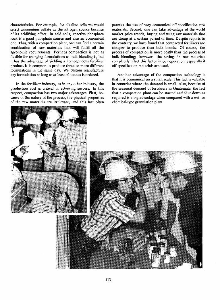
characteristics. For example, for alkaline soils we wouldselect ammonium sulfate as the nitrogen source becauseof its acidifying effect. In acid soils, reactive phosphaterock is a good phosphate source and also an economicalone. Thus, with a compaction plant, one can fmd a certaincombination of raw materials that will fulfill all theagronomic requirements. Perhaps compaction is not asflexible for changing formulations as bulk blending is, butit has the advantage of yielding a homogeneous fertilizerproduct. It is common to produce three or more differentformulations in the same day. We custom manufactureany formulation as long as at least 40 tonnes is ordered.
In the fertilizer industry, as in any other industry, theproduction cost is critical in achieving success. In thisrespect, compaction has two major advantages: First, because of the nature of the process, the physical propertiesof the raw materials are irrelevant, and this fact often
permits the use of very economical off-specification rawmaterials. Second, one can take advantage of the worldmarket price trends, buying and using raw materials thatare cheap at a certain period of time. Despite reports tothe contrary, we have found that compacted fertilizers arecheaper to produce than bulk blends. Of course, theprocess of compaction is more costly than the process ofbulk blending; however, the savings in raw materialscompletely offset this factor in our operation, especially ifoff-specification materials are used.
Another advantage of the compaction technology isthat it is economical on a small scale. This fact is valuablein countries where the demand is small. Also, because ofthe seasonal demand of fertilizers in Guatemala, the factthat a compaction plant can be started and shut down asrequired is a big advantage when compared with a wet- orchemical-type granulation plant.
113
Design Parameters for Bulk-Blending andCompaction/Granulation Plants!
Daniel M. Alt2
Abstract
This paper describes the design parameters. found tobe critical when planning and constructing a blending orcompaction/granulation plant. The logic that should be followed during the design process is described. Also, the special, and often very important, equipment design featuresthat have been learned from experience are discussed.
Bulk-Blending Plants
Bulk blending has emerged as the most economicalprocess for producing NPK fertilizers. This is due to thelarge growth in production and availability of granularproducts (raw materials). A bulk-blending plant requiresless equipment and, therefore, requires less expertise'also, it is a simple process to operate. The two major re~quirements for producing a good-quality bulk blend arethe use of raw materials that are closely matched in sizeand a blending system that is well designed. Bulk blendingallows great flexibility in blending custom grades based onsoil tests and available raw materials.
When designing a bulk-blending plant, the followingquestions should be considered:
1. How much storage is required?2. What materials of construction are available?3. How will the material bins be partitioned?4. H?w will inloading be accomplished - from ship, truck,
rad, or all three?5. What is the required unloading rate? This will usually
be determined by ship or rail demurrage criteria.6. What is the required blending rate? This will be the
main factor in determining equipment layout.7. Will the materials be bagged or loaded out to truck?
1. This paper was originally presented at an IFDC workshop entitled"Supplying Quality Multinutrient Fertilizers in the Latin American andCaribbean Region - Emphasizing Bulk Blending and the Complementary Role of Granulation," October 10-13, 1989, Guatemala City,Guatemala.2. Vice President, Engineering, The A. J. Sackett & SonsCompany- United States.
114
8. How much bagged storage capacity is required?9. What humidity conditions or other special weather con
ditions may affect equipment operation?
A discussion of the design parameters for the major systems follows.
Storage BuildingsThe design of the storage building is based on the
amou~t of raw material to be stored and available buildingmaterIals. The amount of storage required is based onwhether the material is transported by ship, truck, or rail.Raw material received by ship will require a larger storagebuilding than material that is transported by rail or truck.The materials of construction for the buildings are concrete, steel, wood, and mineral composite roofmg. Due tothe corrosiveness of fertilizer, the best materials to use areconcrete and wood.
Inloading SystemThe design parameters for an inloading system are the
unloading rate (tph) and the building profile. The inloading system can load the storage building from the centeror from the end. Loading the storage building at the center requires a drag chain conveyor that can change theangle of.inclination from 0° to 45°. The shuttle conveyor isa re~erslble belt that travels the length of the building toprOVIde access to all the bins. The drag chain conveyorfeeds a reversible shuttle belt conveyor located above thebins. The drag chain conveyor has the advantage of incorporating a large hopper in the tail section that trucks candump into. Because the hopper is part of the conveyor,there is no possibility of spillage at the feed point.
~ading the ~torage bin from the end of the buildingrequlfes a drag fltght conveyor, chain-type bucket elevator,and a belt conveyor the full length of the buildingequipped with a tripper to provide access to the bins. Thistype ~f arrangement involves more equipment and, therefore,. IS more costly. The belt and shuttle conveyor designconsists of three-roll troughing idlers spaced on 4-ft centers. The troughing idlers are usually fabricated of carbonsteel, but the rollers can also be fabricated from plastic
with stainless steel frames. During installation, care mustbe taken to make sure that the idlers are aligned andsquare with the head and tail pulleys. These idlers arefabricated with a 20 tilt which helps to keep the belttrained. On shuttle conveyors where the belt can travel ineither direction, every other idler is installed with an opposite tilt to help in training the belt both ways. It is veryimportant that the idlers be lubricated on a regular basisbecause of the dusty conditions.
Chain-type bucket elevators are recommended insteadof belt-type elevators when handling fertilizer material inhumid climates. Belt-type elevators tend to slip at thehead pulley and burn the belt. The chain has much morepositive traction because of the tooth-type sprocket, and italso requires less maintenance.
The Blending SystemThe design of the blending system is based on the rate
(tph) required. A low rate of blending may only require(1) a mixer mounted on a scale that is charged directly bya payloader, (2) a conveyor, and (3) a bagging hopper witha bagger. This type of system will usually blend 20 tph.Most blending plants require a higher throughputcapacity. In this case, a tower arrangement is required,which will deliver up to 80-100 tph. This throughputcapacity usually will be governed by the capacity of the bagging equipment.
A tower system usually includes a materials conditioner mounted over the boot hopper of an elevator.The materials conditioner is designed to remove (break)lumps from the material; this is essential in humid areaswhere caking may occur o~ the outside of bulk storagepiles. The chain elevator is sized for 90 tph and dischargesto a distributor that channels the material to anyone of sixlS-ton-capacity bins in the overhead hopper system. Eachof the hoppers has a high- and low-level indicator. Theseindicators operate lights on the payloader operator'spanel. From the panel, the payloader operator can determine which bins need to be filled. Each bin is alsoequipped with an air-operated discharge gate.
The material from the overhead hopper is weighedinto a weigh hopper. The weighing mechanism can be allmechanical and have a dial head fitted with an electronicload cell connected to a digital read-out. With theelectronic system, a computerized batching system can beincorporated into the design. The computerized batchingsystem allows one to store up to 60 formulas in "memory."It is also capable of inventory control and can produce amaterial use record and a·summary report of each.
When the system is started, it will automatically weighin the materials for any given formula. After the formula
115
has been weighed, the weigh hopper gate will automatically open to discharge the material into the mixer.
Mixer DesignThere are a number of factors to be considered in the
design of a mixer:
1. Speed of filling the mixer.2. Mixing time required.3. Speed of discharge.4. Mixer capacity.5. Addition of liquids.6. Proven quality of mix.7. Material of construction.
One type of mixer that meets these criteria is a 4-tonpaddle mixer. The paddle mixer can be fed by gravity fromthe weigh hopper in approximately 30 seconds. The mixtime is 60 to 90 seconds, depending upon the number ofingredients and whether a liquid is to be added. Thepaddle mixer can have one to three discharge outlets.With three outlets, 90% of the blend is discharged directlyby gravity without the aid of the mixing paddles. Themixer will take approximately 60 seconds to fully discharge. The total time for a cycle is 2 to 3 minutes.
Handling the Blended ProductThe blended product is conveyed to trucks or bagging
hoppers. The bagging hoppers are equipped with internalpartitions (cells) to prevent segregation. The most common type of bagging system includes an open-mouth bagger, which is accurate and simple to operate, a sewingmachine, and a bagging conveyor.
The major criterion for the design of the hoppers(bagging, product, or other) concerns the valley angles.The valley angle must be steep enough that materials willnot hang up or build up on surfaces or in corners.
Construction MaterialsThe materials of construction are very important since
fertilizer is very corrosive. Type 304 stainless steel shouldbe used in critical areas of the blending tower system. Allmoving parts that come into contact with fertilizer shouldbe made of stainless steel. The critical areas are the rawmaterial distributor,. weigh hopper, discharge gates, mixer,bagger, and bagging conveyor. Equipment that is fabricated of carbon steel should have a durable protectivecoating for prolonged service. The carbon steel issandblasted to remove rust and mill scale, and then a goodprimer and a finish coat of paint are applied. The inside ofthe hoppers can be coated with a coal tar epoxy toprevent deterioration due to the fertilizer, especially inhumid areas.
Compaction/Granulation Plants
Compaction/granulation has gained considerable attention in recent years because of the ability to use dry feedmaterials that are readily available in the world market.Compacting a mixture of the dry fertilizer materialsproduces a homogeneous granule that contains NPK justas does the product from conventional wet-granulationprocesses using a drum-type granulator. The drumgranulator requires liquids such as ammonia, acid, andsteam or water to be injected into the drum to cause thechemical reactions and liquid phase needed to formgranules. The drum granulation method requires moretrained personnel, more equipment, and a more elaboratesystem for recovering fumes and dust (usually some typeof wet scrubber).
The design of a compaction plant requires establishment of the following parameters:
1. What is the required production rate?2. What fertilizer materials will be used?3. What are the humidity conditions or special weather
conditions that may affect equipment operations?4. What area is available for the compaction plant?5. What are the materials available for construction?
The first two questions will determine the compactor sizeand whether multiple production lines are required. Afterthe compactor size has been determined, the peripheralequipment can be designed. The assumption is made thatthe recycle fines-to-product ratio will be 1:1 to 2:1. If therecycle rate is known, then that rate can be used to determine the size of other peripheral equipment. If the rate isnot known, a 2:1 recycle-to-product ratio can be used todetermine the size of this equipment.
The discussion of the compaction/granulation plantdesign will include the following areas:
1. Bulk-blend system.2. Material fed to compactors.3. Compactor.4. Size reduction and screening.5. Dust collection system.6. Electrical system.
Bulk-Blend SystemThe primary raw material feed system for a
compaction/granulation plant is identical to that for thepreviously described bulk-blending plant. After the carefulweighing of each raw material in a batch and propermixing, the mixture is dumped into the continuous feed
116
system for further processing before it enters thecompactors.
Continuous Material Feed System for CompactorThe continuous material feed system consists of
(1) equipment for metering the fresh feed and the recyclefmes, (2) a double-shaft continuous pug mill mixer, and(3) drag chain conveyors. The fresh feed system also requires a mill to grind the previously blended fertilizermaterials. The compactor requires feed material of relatively small particle size to assure good operation and ahomogeneous compacted product. The mill is a doublerow cage mill that will produce a material of which 80% isminus 2O-mesh and 50% is minus 45-mesh. The fresh feedfrom the bulk-blending system is conveyed to the mill by adrag chain conveyor and a bucket elevator. The feed rate .to the mill is controlled by a variable-speed drive on thedrag chain conveyor. The feed rate can be regulated fromthe operator's panel in the control room. The mill ismounted over the fresh feed hopper. The structural steelsupports must be designed to be free of vibration.
The design of the fresh feed hopper must take into account the fact that the material is fme and sometimeshygroscopic. This becomes very important when a blend isused that contains a large amount of urea. The valleyangle of the hopper should be a minimum of 60°. The levelindicators for the hopper should be of the motorizedpaddle type. The size of the hopper depends on the rate ofcompaction; it should be large enough to hold15-30 minutes of production. If the fme material mixture(fresh feed) is sticky, the level of material in the fresh feedhopper is kept at a minimum to avoid plugging.
A screw conveyor at the outlet of the fresh feed hoppermeters the material to the compactors. The screw conveyor is a volumetric type with a variable speed drive. Theinlet of the screw is flared to allow the material to floodthe inlet. The screw is tapered in diameter with the smallest diameter at the extreme feed end. The purpose of thetapered diameter is to obtain an even flow from the entirecross section area of the feed opening.
The recycle fines hopper should follow the samedesign criteria as the fresh feed hopper. The fmes hopper.is also equipped with the same type of variable-speedscrew conveyor that is used on the fresh feed hopper.
The operator is able to control the rates of fresh feedand recycle fines from the operator's panel in the controlroom. The proporti~nof fresh feed to recycle feed shouldbe kept constant. It should be readjusted only if the levelcontrols for the bins indicate that a change in the proportion is required.
Before entering the compactor, the fresh feed andrecycle feed are mixed continuously in a double-shaft pugmill mixer. Additives and/or water can be added to thematerial being mixed. Certain products require a smallpercentage of water to enhance the compactingcapabilities. Care should be taken to avoid too much moisture because this can create additional problems in handling and operation.
After the pug mill, the material flow can be divided bymeans of a two-way valve to go to one or more compactors. The feed material is conveyed to the compactors by adrag chain conveyor. The compactors require a constantand consistent flow of material, and this is accomplishedby the use of two outlets on the conveyor, one over thecompactor and the other at the end of the conveyor toprovide a continuous overflow of material. The overflowgoes to the flake conveyor and is eventually recycled backthrough the system.
Compaction MachineIn selection of a compactor, the following parameters
must be determined on the basis of the product to becompacted:
1. Tons per hour of material to be compacted(production rate).
2. Materials to be compacted.3. Material characteristics and flowability of materials
being processed.
The compactor comprises two counter-rotating rolls;the shaft assembly of one roller is stationary, and theother is movable. The movable roller is pressurized bymeans of a hydraulic system. The material is compacted asit goes through the rolls. The pressure that is applieddepends on the material to be compacted. The counterrotating rolls are force fed by one or more speciallydesigned variable-speed screw feeders located immediately above the compactor rollers.
Size Reduction and ClassificationThe product is discharged from the compactor in the
form of a large sheet or flake. This sheet must be reducedto a form that can be easily conveyed. This can be accomplished with a lump buster that will break the sheetinto pieces of approximately 25 mm or less. The roughlybroken sheet is then conveyed to a double-deck vibratingscreen.
Selection of a screening system is crucial to the overalloperation of the plant and final product sizing. The following design parameters must be established before a screencan be selected:
1. What are the physical properties of the material?2. What type of screening is required - scalping, sizing, or
fmes removal?3. What is the required feed rate?4. What types of screening problems have been encoun-:
tered with similar systems and materials - screen blinding, screen breaking, or the need for excessiverescreening?
5. What are the product size specifications?6. What is the required screening efficiency?
A discussion of the critical design features of the sizereduction and classification equipment follows.
Screens - In fertilizer plants, basically two types ofscreens are used: frame vibrated and cloth vibrated.Frame-vibrated screens are usually horizontal with agyratory screening motion. Cloth-vibrated screens aremounted on an incline with a vibratory screening motionimparted directly to the screen cloth. The cloth-vibratedscreen is most commonly used because it incurs fewerproblems with blinding and requires little manual cleaning. The frame-vibrated screen will require some type ofmechanical system such as bouncing balls (used in theRoteX® unit) to prevent blinding. A double-deck screenseparates the material into oversize, onsize (product), andundersize fractions. The undersize (fines) is sent back tothe recycle hopper and mixed with fresh feed and returnedto the compactor. The product is conveyed to a bagginghopper or storage. The oversize is routed to a mill(crusher) and then returned to the screen.
Crushers - The type of mill or crusher used to reducethe particle size of the compacted sheet is determined bythe amount of recycle generated and the product quality.Vigorous crushing will yield a strong granular product butwill result in a high rate of recycled fines. The type of millused depends on the hardness of the compacted sheet. Ifthe compacted material is hard, then vigorous crushing isrequired. A compacted product containing urea and phosphates often is quite soft. The crushing equipment musthandle the softer product more delicately.
Polishing Drum - A polishing drum is used incompaction/granulation plants to remove the sharp edgesfrom the finished product. Removing sharp edges willdecrease the amount of fines created during handling.After the product leaves the polishing drum, it needs to berescreened to remove the fines. These fines are returnedto the compactor. The product can be sent to storage orbagging.
Dust Collection SystemA dust collection system is installed to control airborne
dust in the plant. The system consists of a fan, cyclones or
117
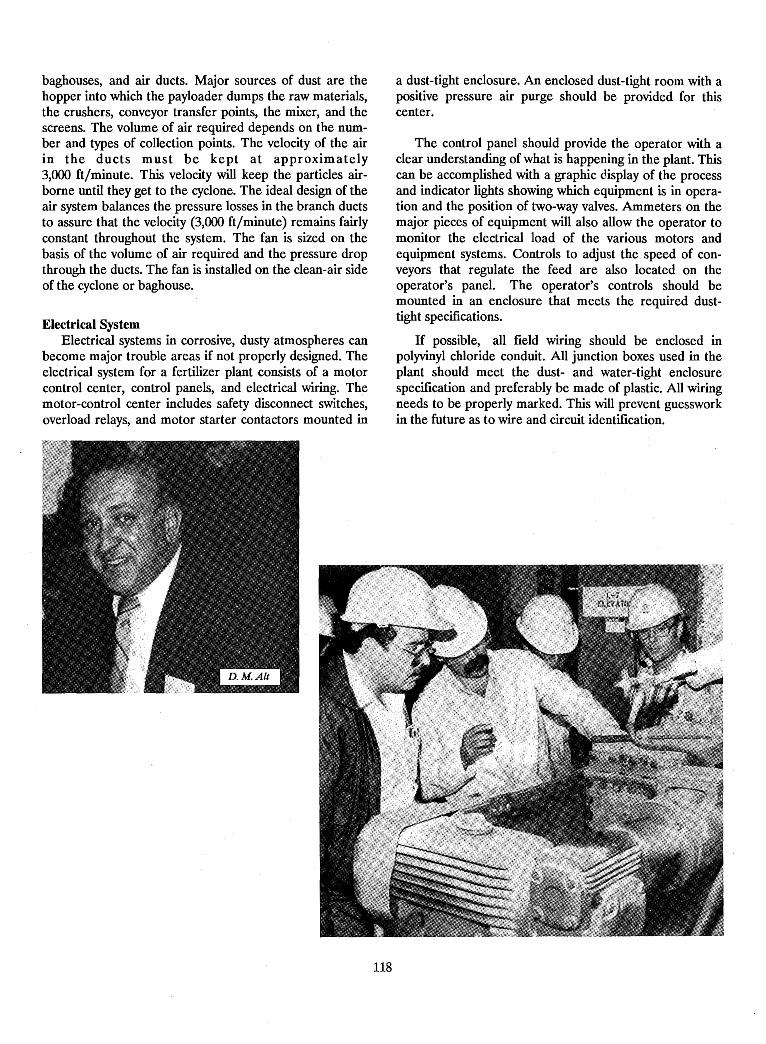
baghouses, and air ducts. Major sources of dust are thehopper into which the payloader dumps the raw materials,the crushers, conveyor transfer points, the mixer, and thescreens. The volume of air required depends on the number and types of collection points. The velocity of the airin the ducts must be kept at approximately3,000 ft/minute. This velocity will keep the particles airborne until they get to the cyclone. The ideal design of theair system balances the pressure losses in the branch ductsto assure that the velocity (3,000 ft/minute) remains fairlyconstant throughout the system. The fan is sized on thebasis of the volume of air required and the pressure dropthrough the ducts. The fan is installed on the clean-air sideof the cyclone or baghouse.
Electrical SystemElectrical systems in corrosive, dusty atmospheres can
become major trouble areas if not properly designed. Theelectrical system for a fertilizer plant consists of a motorcontrol center, control panels, and electrical wiring. Themotor-control center includes safety disconnect switches,overload relays, and motor starter contactors mounted in
a dust-tight enclosure. An enclosed dust-tight room with apositive pressure air purge should be provided for thiscenter.
The control panel should provide the operator with aclear understanding of what is happening in the plant. Thiscan be accomplished with a graphic display of the processand indicator lights showing which equipment is in operation and the position of two-way valves. Ammeters on themajor pieces of equipment will also allow the operator tomonitor the electrical load of the various motors andequipment systems. Controls to adjust the speed of conveyors that regulate the feed are also located on theoperator's panel. The operator's controls should bemounted in an enclosure that meets the required dusttight specifications.
If possible, all field wiring should be enclosed inpolYVinyl chloride conduit. All junction boxes used in theplant should meet the dust- and water-tight enclosurespecification and preferably be made of plastic. All wiringneeds to be properly marked. This will prevent guessworkin the future as to wire and circuit identification.
118
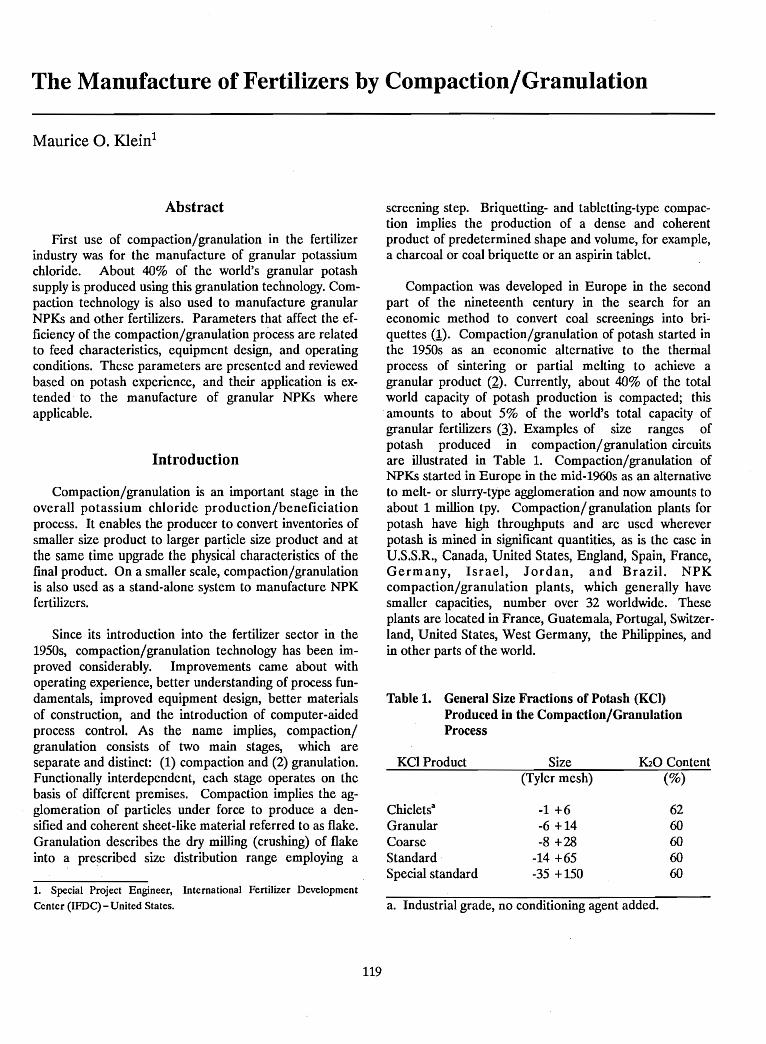
The Manufacture of Fertilizers by Compaction/Granulation
Maurice O. Kleinl
Abstract
First use of compaction/granulation in the fertilizerindustry was for the manufacture of granular potassiumchloride. About 40% of the world's granular potashsupply is produced using this granulation technology. Compaction technology is also used to manufacture granularNPKs and other fertilizers. Parameters that affect the efficiency of the compaction/granulation process are relatedto feed characteristics, equipment design, and operatingconditions. These parameters are presented and reviewedbased on potash experience, and their application is extended· to the manufacture of granular NPKs whereapplicable.
Introduction
Compaction/granulation is an important stage in theoverall potassium chloride production/beneficiationprocess. It enables the producer to convert inventories ofsmaller size product to larger particle size product and atthe same time upgrade the physiciil characteristics of thefinal product. On a smaller scale, compaction/granulationis also used as a stand-alone system to manufacture NPKfertilizers.
Since its introduction into the fertilizer sector in the1950s, compaction/granulation technology has been improved considerably. Improvements came about withoperating experience, better understanding of process fundamentals, improved equipment design, better materialsof construction, and the introduction of computer-aidedprocess control. As the name implies, compaction/granulation consists of two main stages, which areseparate and distinct: (1) compaction and (2) granulation.Functionally interdependent, each stage operates on thebasis of different premises. Compaction implies the agglomeration of particles under force to produce a densified and coherent sheet-like material referred to as flake.Granulation describes the dry milling (crushing) of flakeinto a prescribed size distribution range employing a
1. Special Project Engineer, International Fertilizer Development
Center (IFDC) - United States.
119
screening step. Briquetting- and tabletting-type compaction implies the production of a dense and coherentproduct of predetermined shape and volume, for example,a charcoal or coal briquette or an aspirin tablet.
Compaction was developed in Europe in the secondpart of the nineteenth century in the search for aneconomic method to convert coal screenings into briquettes (1). Compaction/granulation of potash started inthe 1950s as an economic alternative to the thermalprocess of sintering or partial melting to achieve agranular product (2). Currently, about 40% of the totalworld capacity of potash production is compacted; this
.amounts to about 5% of the world's total capacity ofgranular fertilizers (~). Examples of size ranges ofpotash produced in compaction/granulation circuitsare illustrated in Table 1. Compaction/granulation ofNPKs started in Europe in the mid-l960s as an alternativeto melt- or slurry-type agglomeration and now amounts toabout 1 million tpy. Compaction/ granulation plants forpotash have high throughputs and are used whereverpotash is mined in significant quantities, as is the case inU.S.S.R., Canada, United States, England, Spain, France,Germany, Israel, Jordan, and Brazil. NPKcompaction/granulation plants, which generally havesmaller capacities, number over 32 worldwide. Theseplants are located in France, Guatemala, Portugal, Switzerland, United States, West Germany, the Philippines, andin other parts of the world.
Table 1. General Size Fractions of Potash (KCl)Produced in the Compaction/GranulationProcess
KCI Product Size K20 Content(Tyler mesh) (%)
Chicletsa -1 +6 62Granular -6 +14 60Coarse -8 +28 60Standard -14 +65 60Special standard -35 +150 60
a. Industrial grade, no conditioning agent added.
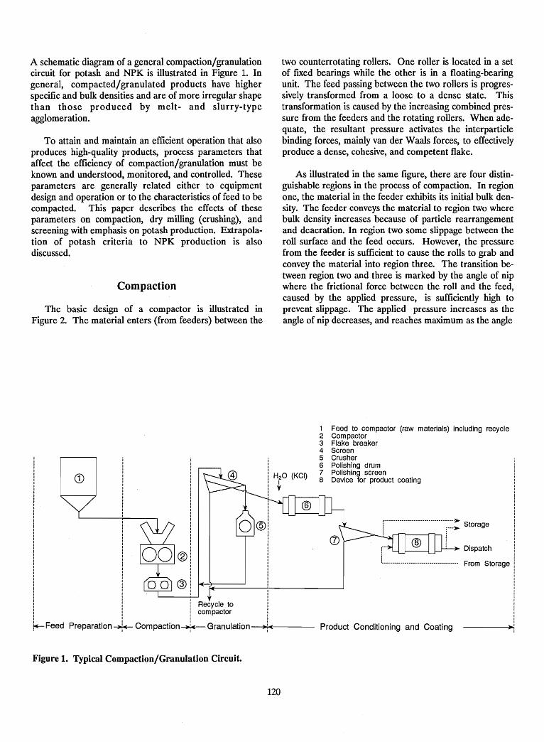
A schematic diagram of a general compaction/granulationcircuit for potash and NPK is illustrated in Figure 1. Ingeneral, compacted/granulated products have higherspecific and bulk densities and are of more irregular shapethan those produced by melt- and slurry-typeagglomeration.
To attain and maintain an efficient operation that alsoproduces high-quality products, process parameters thataffect the efficiency of compaction/granulation must beknown and understood, monitored, and controlled. Theseparameters are generally related either to equipmentdesign and operation or to the characteristics of feed to becompacted. This paper describes the effects of theseparameters on compaction, dry milling (crushing), andscreening with emphasis on potash production. Extrapolation of potash criteria to NPK production is alsodiscussed.
Compaction
The basic design of a compactor is illustrated inFigure 2. The material enters (from feeders) between the
two counterrotating rollers. One roller is located in a setof fixed bearings while the other is in a floating-bearingunit. The feed passing between the two rollers is progressively transformed from a loose to a dense state. Thistransformation is caused by the increasing combined pressure from the feeders and the rotating rollers. When adequate, the resultant pressure activates the interparticlebinding forces, mainly van der Waals forces, to effectivelyproduce a dense, cohesive, and competent flake.
As illustrated in the same figure, there are four distinguishable regions in the process of compaction. In regionone, the material in the feeder exhibits its initial bulk density. The feeder conveys the material to region two wherebulk density increases because of particle rearrangementand deaeration. In region two some slippage between theroll surface and the feed occurs. However, the pressurefrom the feeder is sufficient to cause the rolls to grab andconvey the material into region three. The transition between region two and three is marked by the angle of nipwhere the frictional force between the roll and the feed,caused by the applied pressure, is sufficiently high toprevent slippage. The applied pressure increases as theangle of nip decreases, and reaches maximum as the angle
From Storage
Dispatch
r··································>-i ;..... Storage
: 1
Product Conditioning and Coating
1 Feed to compactor (raw materials) including recycle2 Compactor3 Flake breaker4 Screen5 Crusher6 Polishing drum7 Polishing screen8 Device for product coating
IIIIIIIII
i Recycle toi compactor
Preparation~ Compaction-J.- Granulation-+)o;.ll!(;-------I I I
~Feed
CD
Figure 1. Typical Compaction/Granulation Circuit.
120
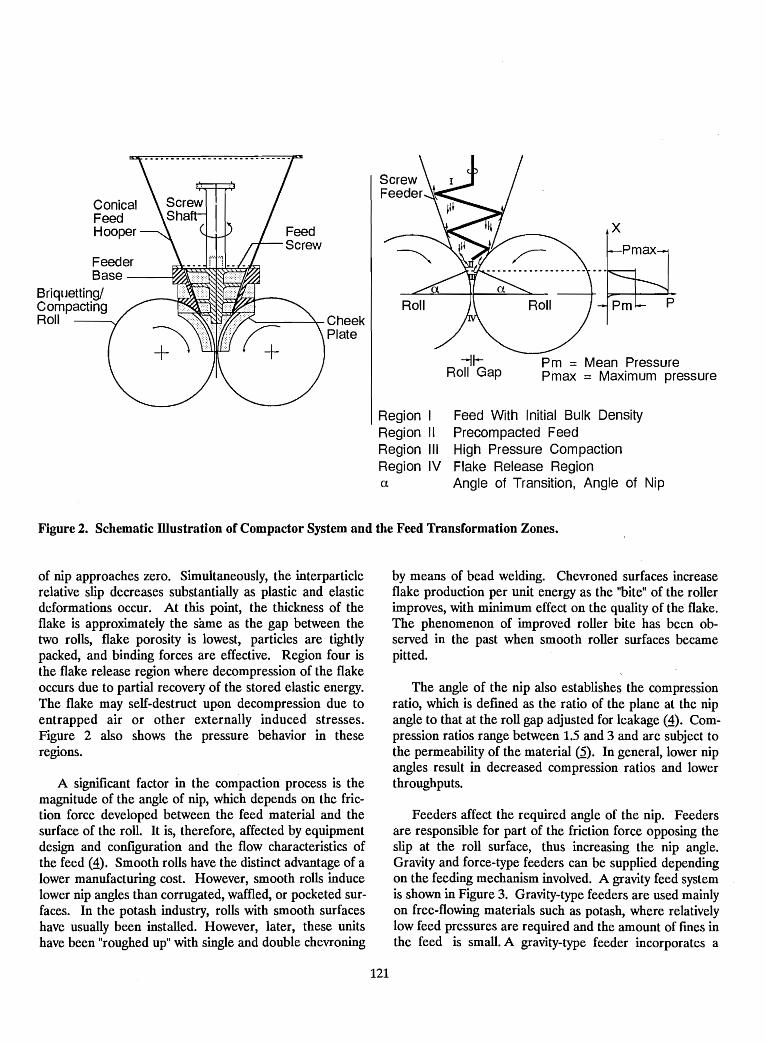
Feed With Initial Bulk DensityPrecompacted FeedHigh Pressure CompactionFlake Release RegionAngle of Transition, Angle of Nip
FeederBase ------'l~A\:::::::::::::
Briquetting/CompactingRoll ~----r- Cheek
Plate
Region IRegion IIRegion IIIRegion IVa
-11Roll Gap
x
Pm = Mean PressurePillax = Maximum pressure
Figure 2. Schematic Illustration of Compactor System and the Feed Transformation Zones.
of nip approaches zero. Simultaneously, the interparticlerelative slip decreases substantially as plastic and elasticdeformations occur. At this point, the thickness of theflake is approximately the same as the gap between thetwo rolls, flake porosity is lowest, particles are tightlypacked, and binding forces are effective. Region four isthe flake release region where decompression of the flakeoccurs due to partial recovery of the stored elastic energy.The flake may self-destruct upon decompression due toentrapped air or other externally induced stresses.Figure 2 also shows the pressure behavior in theseregions.
A significant factor in the compaction process is themagnitude of the angle of nip, which depends on the friction force developed between the feed material and thesurface of the roll. It is, therefore, affected by equipmentdesign and configuration and the flow characteristics ofthe feed (~). Smooth rolls have the distinct advantage of alower manufacturing cost. However, smooth rolls inducelower nip angles than corrugated, waffled, or pocketed surfaces. In the potash industry, rolls with smooth surfaceshave usually been installed. However, later, these unitshave been "roughed up" with single and double chevroning
121
by means of bead welding. Chevroned surfaces increaseflake production per unit energy as the "bite" of the rollerimproves, with minimum effect on the quality of the flake.The phenomenon of improved roller bite has been observed in the past when smooth roller surfaces becamepitted.
The angle of the nip also establishes the compressionratio, which is defmed as the ratio of the plane at the nipangle to that at the roll gap adjusted for leakage (~). Compression ratios range between 1.5 and 3 and are subject tothe permeability of the material (~). In general, lower nipangles result in decreased compression ratios and lowerthroughputs.
Feeders affect the required angle of the nip. Feedersare responsible for part of the friction force opposing theslip at the roll surface, thus increasing the nip angle.Gravity and force-type feeders can be supplied dependingon the feeding mechanism involved. A gravity feed systemis shown in Figure 3. Gravity-type feeders are used mainlyon free-flowing materials such as potash, where relativelylow feed pressures are required and the amount of fmes inthe feed is small. A gravity-type feeder incorporates a
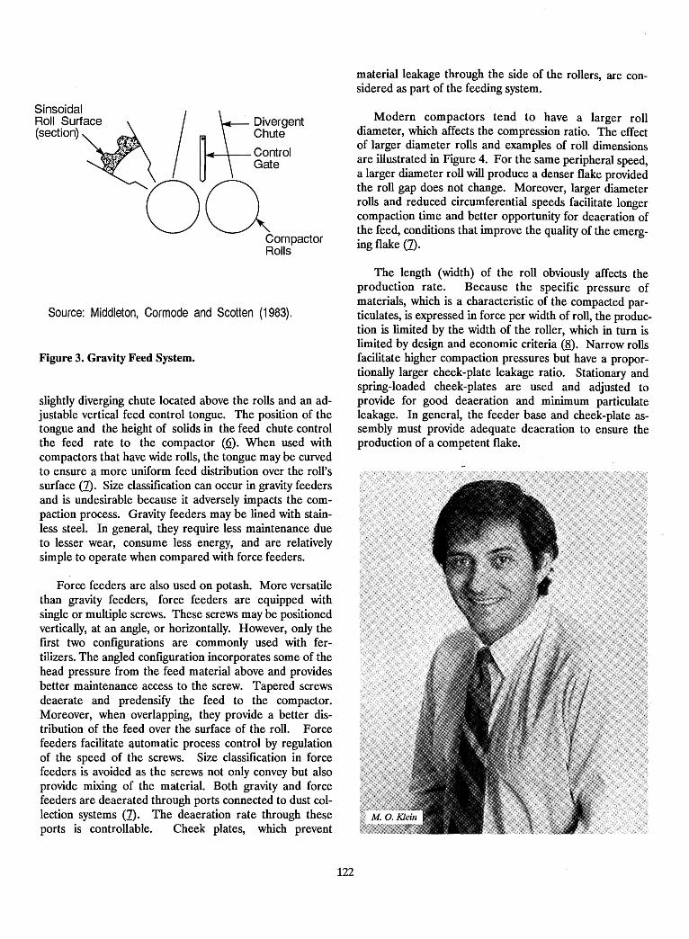
Modern compactors tend to have a larger rolldiameter, which affects the compression ratio. The effectof larger diameter rolls and examples of roll dimensionsare illustrated in Figure 4. For the same peripheral speed,a larger diameter roll will produce a denser flake providedthe roll gap does not change. Moreover, larger diameterrolls and reduced circumferential speeds facilitate longercompaction time and better opportunity for deaeration ofthe feed, conditions that improve the quality of the emerging flake (1).
material leakage through the side of the rollers, are considered as part of the feeding system.
DivergentChute
~--;-- ControlGateI
00CornpactorRolls
SinsoidalRoll Surface(section)
Source: Middleton, Cormode and Scotten (1983).
Figure 3. Gravity Feed System.
slightly diverging chute located above the rolls and an adjustable vertical feed control tongue. The position of thetongue and the height of solids in the feed chute controlthe feed rate to the compactor (Q). When used withcompactors that have wide rolls, the tongue may be curvedto ensure a more uniform feed distribution over the roll'ssurface (1). Size classification can occur in gravity feedersand is undesirable because it adversely impacts the compaction process. Gravity feeders may be lined with stainless steel. In general, they require less maintenance dueto lesser wear, consume less energy, and are relativelysimple to operate when compared with force feeders.
Force feeders are also used on potash. More versatilethan gravity feeders, force feeders are equipped withsingle or multiple screws. These screws may be positionedvertically, at an angle, or horizontally. However, only thefirst two configurations are commonly used with fertilizers. The angled configuration incorporates some of thehead pressure from the feed material above and providesbetter maintenance access to the screw. Tapered screwsdeaerate and predensify the feed to the compactor.Moreover, when overlapping, they provide a better distribution of the feed over the surface of the roll. Forcefeeders facilitate automatic process control by regulationof the speed of the screws. Size classification in forcefeeders is avoided as the screws not only convey but alsoprovide mixing of the material. Both gravity and forcefeeders are deaerated through ports connected to dust collection systems (1). The deaeration rate through theseports is controllable. Cheek plates, which prevent
The length (width) of the roll obviously affects theproduction rate. Because the specific pressure ofmaterials, which is a characteristic of the compacted particulates, is expressed in force per width of roll, the production is limited by the width of the roller, which in turn islimited by design and economic criteria (8). Narrow rollsfacilitate higher compaction pressures but have a proportionally larger cheek-plate leakage ratio. Stationary andspring-loaded cheek-plates are used and adjusted toprovide for good deaeration and minimum particulateleakage. In general, the feeder base and cheek-plate assembly must provide adequate deaeration to ensure theproduction of a competent flake.
122
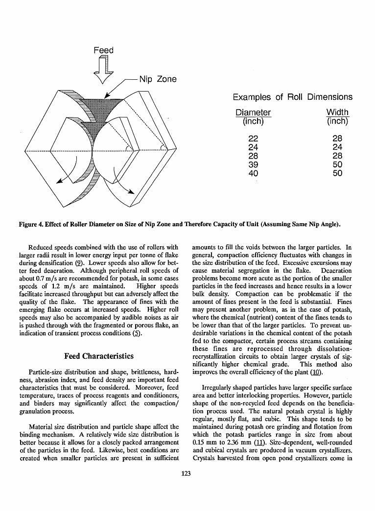
Examples of Roll Dimensions
Zone
Diarneter(inch)
2224283940
Width(inch)
2824285050
Figure 4. Effect of Roller Diameter on Size of Nip Zone and Therefore Capacity of Unit (Assuming Same Nip Angle).
Reduced speeds combined with the use of rollers withlarger radii result in lower energy input per tonne of flakeduring densification (2). Lower speeds also allow for better feed deaeration. Although peripheral roll speeds ofabout 0.7 mls are recommended for potash, in some casesspeeds of 1.2 mls are maintained. Higher speedsfacilitate increased throughput but can adversely affect thequality of the flake. The appearance of fmes with theemerging flake occurs at increased speeds. Higher rollspeeds may also be accompanied by audible noises as airis pushed through with the fragmented or porous flake, anindication of transient process conditions (~).
Feed Characteristics
Particle-size distribution and shape, brittleness, hardness, abrasion index, and feed density are important feedcharacteristics that must be considered. Moreover, feedtemperature, traces of process reagents and conditioners,and binders may significantly affect the compactionlgranulation process.
Material size distribution and particle shape affect thebinding mechanism. A relatively wide size distribution isbetter because it allows for a closely packed arrangementof the particles in the feed. Likewise, best conditions arecreated when smaller particles are present in sufficient
123
amounts to fill the voids between the larger particles. Ingeneral, compaction efficiency fluctuates with changes inthe size distribution of the feed. Excessive excursions maycause material segregation in the flake. Deaerationproblems become more acute as the portion of the smallerparticles in the feed increases and hence results in a lowerbulk density. Compaction can be problematic if theamount of fmes present in the feed is substantial. Finesmay present another problem, as in the case of potash,where the chemical (nutrient) content of the fines tends tobe lower than that of the larger particles. To prevent undesirable variations in the chemical content of the potashfed to the compactor, certain process streams containingthese fines are reprocessed through dissolutionrecrystallization circuits to obtain larger crystals of significantly higher chemical grade. This method alsoimproves the overall efficiency of the plant (10).
Irregularly shaped particles have larger specific surfacearea and better interlocking properties. However, particleshape of the non-recycled feed depends on the beneficiation process used. The natural potash crystal is highlyregular, mostly flat, and cubic. This shape tends to bemaintained during potash ore grinding and flotation fromwhich the potash particles range in size from about0.15 mm to 2.36 mm (11). Size-dependent, well-roundedand cubical crystals are produced in vacuum crystallizers.Crystals harvested from open pond crystallizers come in
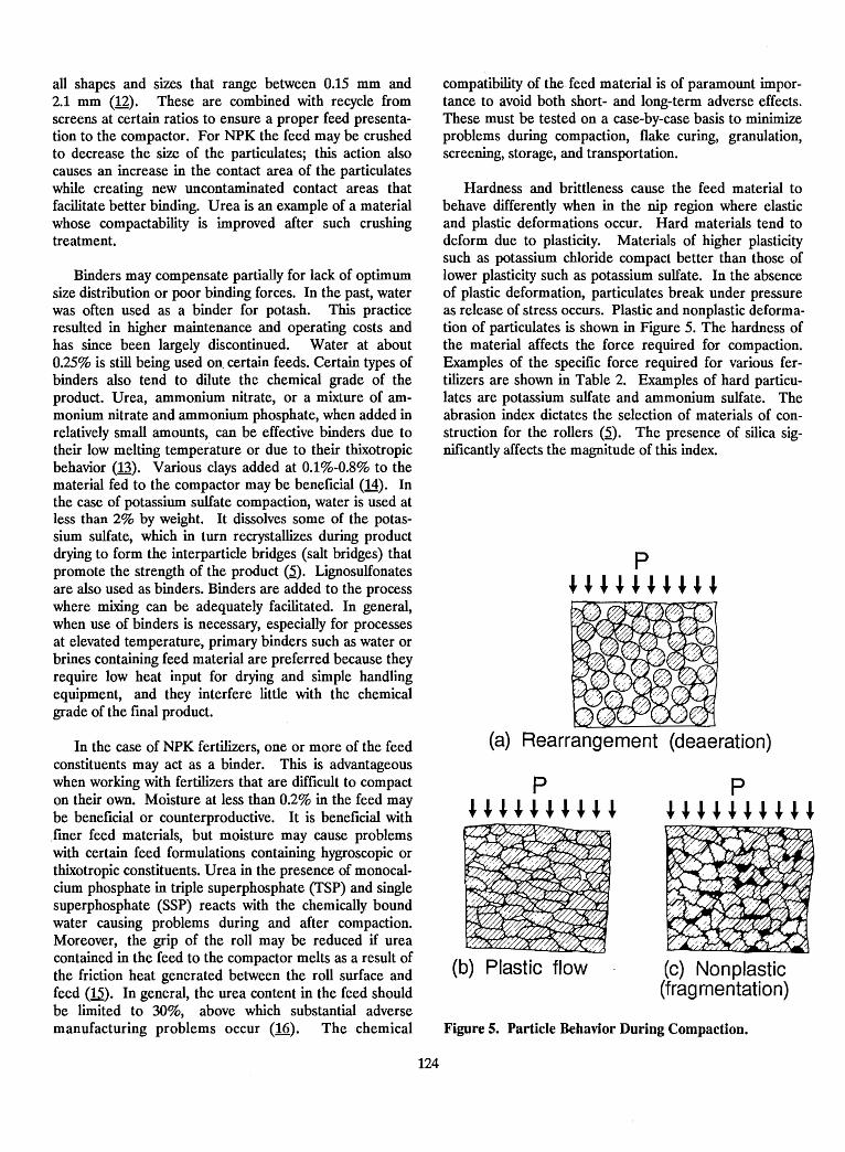
all shapes and sizes that range between 0.15 mm and2.1 mm (12). These are combined with recycle fromscreens at certain ratios to ensure a proper feed presentation to the compactor. For NPK the feed may be crushedto decrease the size of the particulates; this action alsocauses an increase in the contact area of the particulateswhile creating new uncontaminated contact areas thatfacilitate better binding. Urea is an example of a materialwhose compactability is improved after such crushingtreatment.
Binders may compensate partially for lack of optimumsize distribution or poor binding forces. In the past, waterwas often used as a binder for potash. This practiceresulted in higher maintenance and operating costs andhas since been largely discontinued. Water at about0.25% is still being used on, certain feeds. Certain types ofbinders also tend to dilute the chemical grade of theproduct. Urea, ammonium nitrate, or a mixture of ammonium nitrate and ammonium phosphate, when added inrelatively small amounts, can be effective binders due totheir low melting temperature or due to their thixotropicbehavior (13). Various clays added at 0.1%-0.8% to thematerial fed to the compactor may be beneficial (14). Inthe case of potassium sulfate compaction, water is used atless than 2% by weight. It dissolves some of the potassium sulfate, which in turn recrystallizes during productdrying to form the interparticle bridges (salt bridges) thatpromote the strength of the product (~). Lignosulfonatesare also used as binders. Binders are added to the processwhere mixing can be adequately facilitated. In general,when use of binders is necessary, especially for processesat elevated temperature, primary binders such as water orbrines containing feed material are preferred because theyrequire low heat input for drying and simple handlingequipment, and they interfere little with the chemicalgrade of the fmal product.
compatibility of the feed material is of paramount importance to avoid both short- and long-term adverse effects.These must be tested on a case-by-case basis to minimizeproblems during compaction, flake curing, granulation,screening, storage, and transportation.
Hardness and brittleness cause the feed material tobehave differently when in the nip region where elasticand plastic deformations occur. Hard materials tend todeform due to plasticity. Materials of higher plasticitysuch as potassium chloride compact better than those oflower plasticity such as potassium sulfate. In the absenceof plastic deformation, particulates break under pressureas release of stress occurs. Plastic and nonplastic deformation of particulates is shown in Figure 5. The hardness ofthe material affects the force required for compaction.Examples of the specific force required for various fertilizers are shown in Table 2. Examples of hard particulates are potassium sulfate and ammonium sulfate. Theabrasion index dictates the selection of materials of construction for the rollers (~). The presence of silica significantly affects the magnitude of this index.
Figure 5. Particle Behavior During Compaction.
(a) Rearrangement (deaeration)
(c) Nonplastic(frag rnentation)
(b) Plastic flow
In the case of NPK fertilizers, one or more of the feedconstituents may act as a binder. This is advantageouswhen working with fertilizers that are difficult to compacton their own. Moisture at less than 0.2% in the feed maybe beneficial or counterproductive. It is beneficial with,finer feed materials, but moisture may cause problemswith certain feed formulations containing hygroscopic orthixotropic constituents. Urea in the presence of monocalcium phosphate in triple superphosphate (TSP) and singlesuperphosphate (SSP) reacts with the chemically boundwater causing problems during and after compaction.Moreover, the grip of the roll may be reduced if ureacontained in the feed to the compactor melts as a result ofthe friction heat generated between the roll surface andfeed (15). In general, the urea content in the feed shouldbe limited to 30%, above which substantial adversemanufacturing problems occur (16). The chemical
124
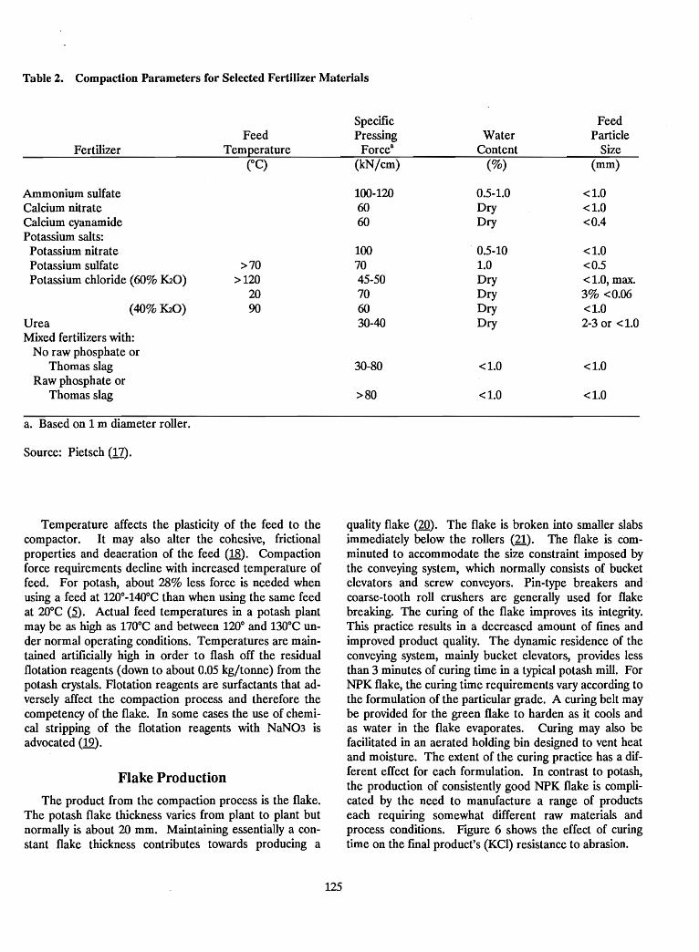
Table 2. Compaction Parameters for Selected Fertilizer Materials
Fertilizer
Ammonium sulfateCalcium nitrateCalcium cyanamidePotassium salts:
Potassium nitratePotassium sulfatePotassium chloride (60% K20)
(40% K20)UreaMixed fertilizers with:
No raw phosphate orThomas slag
Raw phosphate orThomas slag
a. Based on 1 m diameter roller.
Source: Pietsch (17).
FeedTemperature
>70>120
2090
Specific FeedPressing Water Particle
Force8 Content Size(kN/cm) (%) (mm)
100-120 0.5-1.0 <1.060 Dry <1.060 Dry <0.4
100 0.5-10 <1.070 1.0 <0.545-50 Dry <LOt max.70 Dry 3% <0.0660 Dry <1.030-40 Dry 2-3 or <1.0
30-80 <1.0 <1.0
>80 <1.0 <1.0
Temperature affects the plasticity of the feed to thecompactor. It may also alter the cohesivet frictionalproperties and deaeration of the feed (18). Compactionforce requirements decline with increased temperature offeed. For potasht about 28% less force is needed whenusing a feed at 120°-140°C than when using the same feedat 20°C (~). Actual feed temperatures in a potash plantmay be as high as 170°C and between 120° and 130°C under normal operating conditions. Temperatures are maintained artificially high in order to flash off the residualflotation reagents (down to about 0.05 kg/tonne) from thepotash crystals. Flotation reagents are surfactants that adversely affect the compaction process and therefore thecompetency of the flake. In some cases the use of chemical stripping of the flotation reagents with NaN03 isadvocated (19).
Flake Production
The product from the compaction process is the flake.The potash flake thickness varies from plant to plant butnormally is about 20 mm. Maintaining essentially a constant flake thickness contributes towards producing a
125
quality flake (20). The flake is broken into smaller slabsimmediately below the rollers (21). The flake is comminuted to accommodate the size constraint imposed bythe conveying systemt which normally consists of bucketelevators and screw conveyors. Pin-type breakers andcoarse-tooth roll crushers are generally used for flakebreaking. The curing of the flake improves its integrity.This practice results in a decreased amount of fines andimproved product quality. The dynamic residence of theconveying systemt mainly bucket elevatorst provides lessthan 3 minutes of curing time in a typical potash mill. ForNPK flaket the curing time requirements vary according tothe formulation of the particular grade. A curing belt maybe provided for the green flake to harden as it cools andas water in the flake evaporates. Curing may also befacilitated in an aerated holding bin designed to vent heatand moisture. The extent of the curing practice has a different effect for each formulation. In contrast to potash,the production of consistently good NPK flake is complicated by the need to manufacture a range of productseach requiring somewhat different raw materials andprocess conditions. Figure 6 shows the effect of curingtime on the [mal product's (KCI) resistance to abrasion.
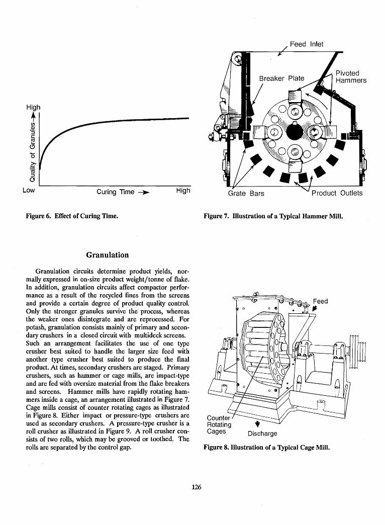
High
+CJ)Q)
"Sc:rnc!;'6~(ij:Jo
Low Curing Time ~ High Grate Bars Product Outlets
Figure 6. Effect of Curing Time.
Granulation
Granulation circuits determine product yields, normallyexpressed in on-size product weight/tonne of flake.In addition, granulation circuits affect compactor performance as a result of the recycled fmes from the screensand provide a certain degree of product quality control.Only the stronger granules survive the process, whereasthe weaker ones disintegrate and are reprocessed. Forpotash, granulation consists mainly of primary and secondary crushers in a closed circuit with multideck screens.Such an arrangement facilitates the use of one typecrusher best suited to handle the larger size feed withanother type crusher best suited to produce the fmalproduct. At times, secondary crushers are staged. Primarycrushers, such as hammer or cage mills, are impact-typeand are fed with oversize material from the flake breakersand screens. Hammer mills have rapidly rotating hammers inside a cage, an arrangement illustrated in Figure 7.Cage mills consist of counter rotating cages as illustratedin Figure 8. Either impact or pressure-type crushers areused as secondary crushers. A pressure-type crusher is aroll crusher as illustrated in Figure 9. A roll crusher consists of two rolls, which may be grooved or toothed. Therolls are separated by the control gap.
126
Figure 7. Illustration of a Typical Hammer Mill.
Discharge
Figure 8. Illustration of a Typical Cage Mill.
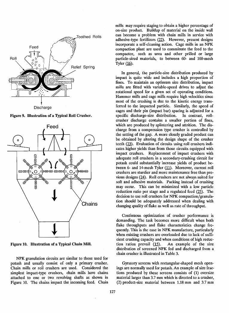
Continuous optimization of crusher performance isdemanding. The task becomes more difficult when bothflake throughputs and flake characteristics change frequently. This is the case in NPK manufacture, particularlywhen existing crushers are overloaded due to lack of sufficient crushing capacity and when conditions of high reduction ratios prevail (15). An example of the sizedistribution of screened NPK fed and discharged from achain crusher is illustrated in Table·3.
In general, the particle-size distribution produced byimpact is quite wide and includes a high proportion offmes. To maintain an optimum size distribution, impactmills are fitted with variable-speed drives to adjust therotational speed for a given set of operating conditions.Hammer mills and cage mills require high velocities sincemost of the crushing is due to the kinetic energy transferred to the impacted particle. Similarly, the speed ofcages and their pin (impact bar) spacing is adjusted for aspecific discharge-size distribution. In contrast, rollcrusher discharge contains a smaller portion of fmes,which are produced by splintering and attrition. The discharge from a compression type crusher is controlled bythe setting of the gap. A more closely graded product canbe obtained by altering the design shape of the crusherteeth (23). Evaluation of circuits using roll crushers indicates higher yields than from those circuits equipped withimpact crushers. Replacement of impact crushers withadequate roll crushers in a secondary-crushing circuit forpotash could substantially increase yields of product between 6- and 14-mesh Tyler (11). Moreover, current rollcrushers are sturdier and more maintenance free than previous designs (24). Roll crushers are not always suited forsoft and adhesive materials. Packing instead of crushingmay occur. This can be minimized with a low particlereduction ratio per stage and a regulated feed (25). Thedecision to use roll crushers for NPK compaction/granulation should be adequately addressed when dealing withchanging quality of flake as well as rate of throughput.
mills may require staging to obtain a higher percentage ofon-size product. Buildup of material on the inside wallcan become a problem with chain mills in service withadhesive-type fertilizers (22). However, present designsincorporate a self-cleaning action. Cage mills in an NPKcompaction plant are used to comminute the feed to thecompactor, such as urea and other prilled or largeparticle-sized materials, to between 60- and 100-meshTyler (16).
Toothed Rolls
Feed
Figure 10. Illustration of a Typical Chain Mill.
Discharge
Figure 9. Illustration of a Typical Roll Crusher.
NPK granulation circuits are similar to those used forpotash and usually consist of only a primary crusher.Chain mills or roll crushers are used. Considered thesimplest impact-type crushers, chain mills have chainsattached to one or two revolving shafts as shown inFigure 10. The chains impact the incoming feed. Chain
Gyratory screens with rectangular-shaped mesh openings are normally used for potash. An exampie of size fractions produced by these screens consists of (1) oversizematerial larger than 3.7 mm which is directed to a crusher,(2) product-size material between 1.18 mm and 3.7 mm
127
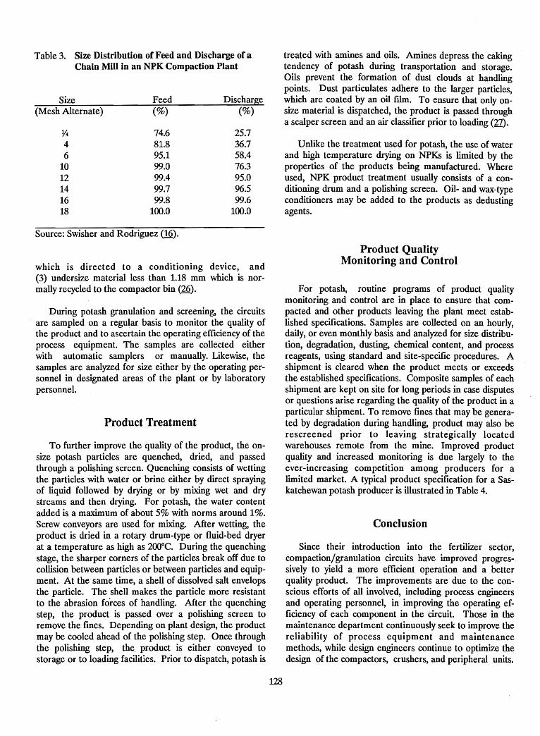
Table 3. Size Distribution of Feed and Discharge of aChain Mill in an NPK Compaction Plant
Size Feed Discharge(Mesh Alternate) (%) (%)
~ 74.6 25.74 81.8 36.76 95.1 58.4
10 99.0 76.312 99.4 95.014 99.7 96.516 99.8 99.618 100.0 100.0
Source: Swisher and Rodriguez (16).
which is directed to a conditioning device, and(3) undersize material less than 1.18 mm which is normally recycled to the compactor bin (26).
During potash granulation and screening, the circuits. are sampled on a regu~ar basis to monitor the quality of
the product and to ascertain the operating efficiency of theprocess equipment. The samples are collected eitherwith automatic samplers or manually. Likewise, thesamples are analyzed for size either by the operating personnel in designated areas of the plant or by laboratorypersonnel.
Product Treatment
To further improve the quality of the product, the onsize potash particles are quenched, dried, and passedthrough a polishing screen. Quenching consists of wettingthe particles with water or brine either by direct sprayingof liquid followed by drying or by mixing wet and drystreams and then drying. For potash, the water contentadded is a maximum of about 5% with norms around 1%.Screw conveyors are used for mixing. After wetting, theproduct is dried in a rotary drum-type or fluid-bed dryerat a temperature as high as 200°C. During the quenchingstage, the sharper corners of the particles break off due tocollision between particles or between particles and equipment. At the same time, a shell of dissolved salt envelopsthe particle. The shell makes the particle more resistantto the abrasion forces of handling. After the quenchingstep, the product is passed over a polishing screen toremove the fines. Depending on plant design, the productmay be cooled ahead of the polishing step. Once throughthe polishing step, the. product is either conveyed tostorage or to loading facilities. Prior to dispatch, potash is
128
treated with amines and oils. Amines depress the cakingtendency of potash during transportation and storage.Oils prevent the formation of dust clouds at handlingpoints. Dust particulates adhere to the larger particles,which are coated by an oil filin. To ensure that only onsize material is dispatched, the product is passed througha scalper screen and an air classifier prior to loading (27).
Unlike the treatment used for potash, the use of waterand high temperature drying on NPKs is limited by theproperties of the products being manufactured. Whereused, NPK product treatment usually consists of a conditioning drum and a polishing screen. Oil- and wax-typeconditioners may be added to the products as dedustingagents.
Product QualityMonitoring and Control
For potash, routine programs of product qualitymonitoring and control are in place to ensure that compacted and other products leaving the plant meet established specifications. Samples are collected on an hourly,daily, or even monthly basis and analyzed for size distribution, degradation, dusting, chemical content, and processreagents, using standard and site-specific procedures. Ashipment is cleared when the product meets or exceedsthe established specifications. Composite samples of eachshipment are kept on site for long periods in case disputesor questions arise regarding the quality of the product in aparticular shipment. To remove fmes that may be generated by degradation during handling, product may also berescreened prior to leaving strategically locatedwarehouses remote from the mine. Improved productquality and increased monitoring is due largely to theever-increasing competition among producers for alimited market. A typical product specification for a Saskatchewan potash producer is illustrated in Table 4.
Conclusion
Since their introduction into the fertilizer sector,compaction/granulation circuits have improved progressively to yield a more efficient operation and a betterquality product. The improvements are due to the conscious efforts of all involved, including process engineersand operating personnel, in improving the operating efficiency of each component in the circuit. Those in themaintenance department continuously seek to improve thereliability of process equipment and maintenancemethods, while design engineers continue to optimize thedesign of the compactors, crushers, and peripheral units.
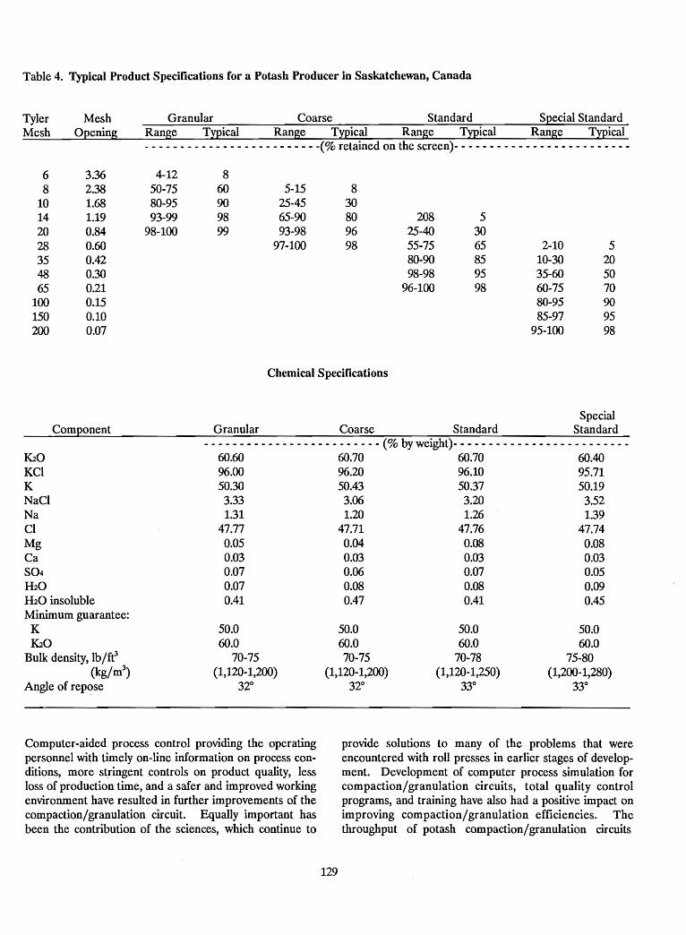
Table 4. Typical Product Specifications for a Potash Producer in Saskatchewan, Canada
Tyler MeshMesh Opening
6 3.368 2.38
10 1.6814 1.1920 0.8428 0.6035 0.4248 0.3065 0.21
100 0.15150 0.10200 0.07
Component
1<20KClKNaClNaCIMgCaS04H20H20 insolubleMinimum guarantee:K1<20
Bulk density, lb/fe(kg/m3
)
Angle of repose
Granular Coarse Standard Special StandardRange Typical Range Typical Range Typical Range Typical- - - - - - - - - - - - - - - - - - - - - - - - -(% retained on the screen)- - - - - - - - - - - - - - - - - - - - - - - - -
4-12 850-75 60 5-15 880-95 90 25-45 3093-99 98 65-90 80 208 5
98-100 99 93-98 96 25-40 3097-100 98 55-75 65 2-10 5
80-90 85 10-30 2098-98 95 35-60 50
96-100 98 60-75 7080-95 9085-97 95
95-100 98
Chemical Specifications
SpecialGranular Coarse Standard Standard
- - - - - - - - - - - - - - - - - - - - - - - - - (% by weight)- - - - - - - - - - - - - - - - - - - - - - - - -60.60 60.70 60.70 60.4096.00 96.20 96.10 95.7150.30 50.43 50.37 50.193.33 3.06 3.20 3.521.31 1.20 1.26 1.39
47.77 47.71 47.76 47.74Oili QW om omom om om omom o~ om Oili0.07 0.08 0.08 0.090.41 0.47 0.41 0.45
50.0 50.0 50.0 50.060.0 60.0 60.0 60.0
70-75 70-75 70-78 75-80(1,120-1,200) (1,120-1,200) (1,120-1,250) (1,200-1,280)
320 320 330 330
Computer-aided process control providing the operatingpersonnel with timely on-line information on process conditions, more stringent controls on product quality, lessloss of production time, and a safer and improved workingenvironment have resulted in further improvements of thecompaction/granulation circuit. Equally important hasbeen the contribution of the sciences, which continue to
129
provide solutions to many of the problems that wereencountered with roll presses in earlier stages of development. Development of computer process simulation forcompaction/granulation circuits, total quality controlprograms, and training have also had a positive impact onimproving compaction/granulation efficiencies. Thethroughput of potash compaction/granulation circuits
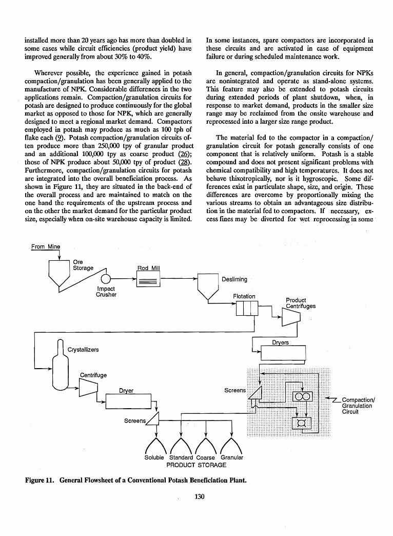
installed more than 20 years ago has more than doubled insome cases while circuit efficiencies (product yield) haveimproved generally from about 30% to 40%.
Wherever possible, the experience gained in potashcompaction/granulation has been generally applied to themanufacture of NPK. Considerable differences in the twoapplications remain. Compaction/granulation circuits forpotash are designed to produce continuously for the globalmarket as opposed to those for NPK, which are generallydesigned to meet a regional market demand. Compactorsemployed in potash may produce as much as 100 tph offlake each (2). Potash compaction/granulation circuits often produce more than 250,000 tpy of granular productand an additional 100,000 tpy as coarse product (26);those of NPK produce about 50,000 tpy of product (28).Furthermore, compaction/granulation circuits for potashare integrated into the overall beneficiation process. Asshown in Figure 11, they are situated in the back-end ofthe overall process and are maintained to match on theone hand the requirements of the upstream process andon the other the market demand for the particular productsize, especially when on-site warehouse capacity is limited.
From Mine
In some instances, spare compactors are incorporated inthese circuits and are activated in case of equipmentfailure or during scheduled maintenance work.
In general, compaction/granulation circuits for NPKsare nonintegrated and operate as stand-alone systems.This feature may also be extended to potash circuitsduring extended periods of plant shutdown, when, inresponse to market demand, products in the smaller sizerange may be reclaimed from the onsite warehouse andreprocessed into a larger size range product.
The material fed to the compactor in a compaction/granulation circuit for potash generally consists of onecomponent that is relatively uniform. Potash is a stablecompound and does not present significant problems withchemical compatibility and high temperatures. It does notbehave thixotropically, nor is it hygroscopic. Some differences exist in particulate shape, size, and origin. Thesedifferences are overcome by proportionally mixing thevarious streams to obtain an advantageous size distribution in the material fed to compactors. If necessary, excess fmes may be diverted for wet reprocessing in some
!\!\!\!\Soluble Standard Coarse Granular
PRODUCT STORAGE
Figure 11. General Flowsheet of a Conventional Potash Beneficiation Plant.
130
cases. By and large, the quality and rate of feed to the compactors is predictable and controlled to obtain a flake ofimproved quality, which can also be efficiently granulatedto produce a good quality product.
In contrast, in the manufacture of NPKs the materialfed to the compactor may vary with each product manufactured. The chemical characteristics and the compatibilityof certain feed constituents limit their use below the levelat which they become problematic. Such is the case withurea, which is hygrOSCOpic and thixotropic. Alternatively,substandard feedstock (material which from a qualitystandpoint would not be suitable for direct sale) may beused, often resulting in a substantial saving inoperating costs. Compared with potash, NPK compaction/
granulation plants, in general, produce substantiallysmaller quantities of products having many different formulations (components).
For three decades, compaction/granulation circuitshave been an integral part in the manufacture of granularfertilizer. They offer a proven and economical alternativefor size-upgrading of fertilizers in the production of potassium chloride, potassium sulfate, NPKs, and ammoniumsulfate (29). Production economics for NPK compaction/granulation tend to favor regional markets larger than25,000 tpy (30). Compaction/granulation technology mustbe properly considered in comparison with other granulation alternatives that may be used to meet the specificneeds of a regional market.
References
1. Klein, M., and W. Popiel. 1985. "Agglomeration inthe Fertilizer Industry," IN Potash Technology 1983,R. M. McKercher (Ed.), Pergamon Press, Willowdale, Ontario, Canada.
2. Noyes, R. 1965. Potash and Potassium Fertilizers,Chemical Process Monograph Series, Park Ridge,New Jersey, U.SA.
3. Schultz, J. J., and J. R. Polo. 1988. "The Role ofAgglomeration in the Fertilizer Industry," IN NPKFertilizer Production Alternatives, Proceedings,J. J. Schultz and E. D. Frederick (Eds.), IFDC-SP-9,International Fertilizer Development Center, MuscleShoals, Alabama, U.SA.
4. Von Dreele, C. W. 1973. "Roll Type Compactingand Briquetting," Mineral Processing, July.
5. Zisselmar, K. 1988. "Compaction/Granulation ofFertilizers," IN NPK Fertilizer Production Alternatives,Proceedings, J. J. Schultz and E. D. Frederick (Eds.),IFDC-SP-9, International Fertilizer DevelopmentCenter, Muscle Shoals, Alabama, U.SA.
6. Johanson, J. R. 1977. "Use of Theory for Designand Selection of Roll Presses for Agglomeration andCompaction," IN The Institute for BriqueUing andAgglomeration (IBA) Conference Proceedings.
7. Pietsch, W. 1987. Roll Pressing, Second Edition,Powder Advisory Centre, London, England.
8. Lupin, S. M. 1984. "Techno-Economics ofCompaction/Granulation Process," Fertilizer News,December.
131
9. Pietsch, W. B. 1983. "Modern Equipment andPlants for Potash Granulation," IN Potash Technology 1983, R. M. McKercher (Ed.), Pergamon Press,Willowdale, Ontario, Canada.
10. Klein, M., and A. Roy. 1990. "Potassium Chloride:Aspects of Extraction Technologies," Paperpresented at the Second Workshop on West AfricanAgrominerals, February 27-March 1, 1990, Lome,Togo.
11. Hogan, H. 1983. "A Review of Crushing SystemsUsed in the Compaction Plant at PCS Mining,Lanigan Division," IN Potash Technology 1983,R. M. McKercher (Ed.), Pergamon Press, Willowdale, Ontario, Canada.
12. Goldsmith, E. L., and M. O. Klein. 1989."Potassium Chloride Crystallization inSaskatchewan," IN Proceedings of 2nd InternationalConference on Separation Science and Technology,M.H.I. Baird and S. Vijayan, (Eds.), Hamilton,Ontario, Canada, October 1-4.
13. Brown, G. G. 1967. "Process for CompactingMuriate of Potash," British Patent #1076682.
14. Jackson, H. E., A. G. White, and C. R. Kirby. 1976."Compaction of Potash," Canadian PatentNo. 988315, May 4.
15. Sutter, A. 1990. "Production and Marketing of Compacted NPKs in Switzerland: Rationale and Results,"IN Proceedings: Supplying Quality MultinutrientFertilizers in the Latin American and Caribbean
Region - Emphasizing Bulk Blending and the Complementary Role of Granulation, J. J. Schultz andE. D. Frederick (Eds.), IFDC-SP-14, InternationalFertilizer Development Center, Muscle Shoals,Alabama, V.SA.
16. Swisher, M. A., and C. Rodriguez. 1988."Compaction of NPK Fertilizers for the GuatemalanMarket," IN Proceedings of the 35th Annual Meeting,Fertilizer Industry Round Table, November 14-16,Baltimore, Maryland, V.SA.
17. Pietsch, W. B. 1989. "History, Application, andPresent Status of Mixed Fertilizer Granulation byCompaction," IN Proceedings of Fertilizer LatinAmerica Conference, Caracas, Venezuela, The BritishSulphur Corporation Ltd., London, England.
18. Johanson, J. R. 1979. "Two-Phase-Flow Effects inSolids Processing and Handling," Chemical Engineering, January l.
19. Medemblik, L. 1983. "Compaction of PotassiumChloride in the French Potash Industry," IN PotashTechnology 1983, R. M. McKercher (Ed.), PergamonPress, Willowdale, Ontario, Canada.
20. Johanson, J. R., and A. F. Banks. 1975. "AchievingHigher Production Rates V sing Existing Roll Pressesfor Potash," IN The Institute for Briqueuing andAgglomeration (IBA) Conference Proceedings.
21. Middleton, A. S., D. A. Cormode, and J. E. Scotten.1983. "Compaction Plant Expansion Process Designand Equipment Selection at Cominco Ltd.," INPotash Technology 1983, R. M. McKercher (Ed.),Pergamon Press, Willowdale, Ontario, Canada.
22. Norton, M. M., B. R. Parker, and J. R. Stumpe.1979. "Review of Size Reduction and Classification
in Fertilizer Processes," Paper presented at theAnnual Meeting of the American Chemical Society,Washington, D.C., September 9-14.
23. Ratcliffe, A. 1972. "Crushing and Grinding," Processing, July.
24. Eatock, B. 1985. "Advances in Potassium Miningand Refming," IN Potassium in Agriculture, AmericanSociety of Agronomy, Madison, Wisconsin, V.SA.
25. Anon. 1980. Crnshing Practice and Theory, AllisChalmer's Bulletin 07-R-8073-02.
26. Patterson, M. A. 1983. "Contemporary Design ofAdd-On or Stand-Alone Compaction Facilities," INPotash Technology 1983, R. M. McKercher (Ed.),Pergamon Press, Willowdale, Ontario, Canada.
27. Banks, A. F. 1978. "Milling of Potash in Canada,"CIM Proceedings.
28. Chupungco, E. J., and W. B. Pietsch. 1990. "SouthEast Asia's First Fertilizer Compaction Plant," Phosphorus and Potassium No 165, The British SulphurCorporation Ltd., London, England.
29. Mickus, J. C., and C. Bowen. 1988. "VariousMethods for Producing Granular Ammonium SulfateFrom Byproduct Fines," IN Proceedings of the 35thAnnual Meeting, Fertilizer Industry Round Table,November 14-16, Baltimore, Maryland, V.SA.
30. Anon. 1986. "Bulk Blending and Compacting ofFertilizers," Agro Chemical News in Brief, FertilizerAdvisory, Development, and Information Networkfor Asia and the Pacific, Vol. IX, No.2, April.
132
Pilot-Plant DeInonstration of Selected Operating ParaDletersfor the Production of Granular Urea-Based NPKs
George W. Bolds 1111
Introduction
The difficulties involved in producing granular NPKfertilizers are greatly increased when the formulation contains 5% or more urea. The main problems encounteredwith the urea-containing products are increased hygroscopicity, adduction, and sensitivity to heat. Many plantdesigners and producers have failed to pay proper attention to these dangers and as a result have suffered operational difficulties.
The purpose of the IFDC pilot-plant operations conducted during the workshop was to demonstrate theproduction of urea-based NPK granular fertilizers undercorrect and incorrect conditions. The demonstrations conducted under correct conditions showed that granularurea-based NPK fertilizers can be produced successfullywhen the parameters required by the presence of urea arefollowed. The demonstrations using conventional ammonium phosphate-based operating parameters weredesigned to show the problems that are usually encountered when attempting to produce urea-based fertilizersunder such conditions.
Production Formulations
The fertilizer grade chosen for the pilot-plantdemonstrations was a 17-17-17-2MgO, a typical gradeproduced and used in the tropics. Two formulations wereused to produce this grade (Tables 1 and 2). The particlesize specifications·for the solid raw materials fed to thegranulator are shown in Table 3. Both formulations contain 30% urea (fed as an anhydrous melt), potassiumchloride, sulfate of potash-magnesium (SPM), and powdered monoammonium phosphate (MAP). The secondformulation (Table 2) differs from the frrst in that a portion (20%) of the P20S is supplied by phosphoric acidsprayed onto the bed of material in the granulator and
1. Pilot Plant Operations Coordinator, International Fertilizer
Development Center (IFDC) - United States.
133
then ammoniated to an NH3:H3P04 mole ratio of 1.0. Theremainder of the P20S (80%) is obtained from powderedMAP. This formulation adjustment demonstrates onemethod for improving the plant water balance by substituting phosphoric acid for water in the scrubber and recovering the scrubber liquor and its P20S value in the process.This, of course, assumes that ammonia and phosphoricacid are available at the plant site.
Demonstration Objectives
The three pilot-plant demonstrations were designed toshow (1) well-controlled production when using 30% ureain the formulation; (2) the effect of increasing the dryerexit gas temperature from the optimum value of about70°C to 93°C, which led to melting (stickiness) in the dryerand necessitated a plant shutdown; and (3) the effect ofswitching from cool to hot screening (bypassing theprocess cooler and routing the dryer discharge materialdirectly to the screens), which led to blinding of thescreens due to temperature-induced plasticity of the fertilizer material. The problems highlighted by thesedemonstrations are those most often encountered in commercial operations.
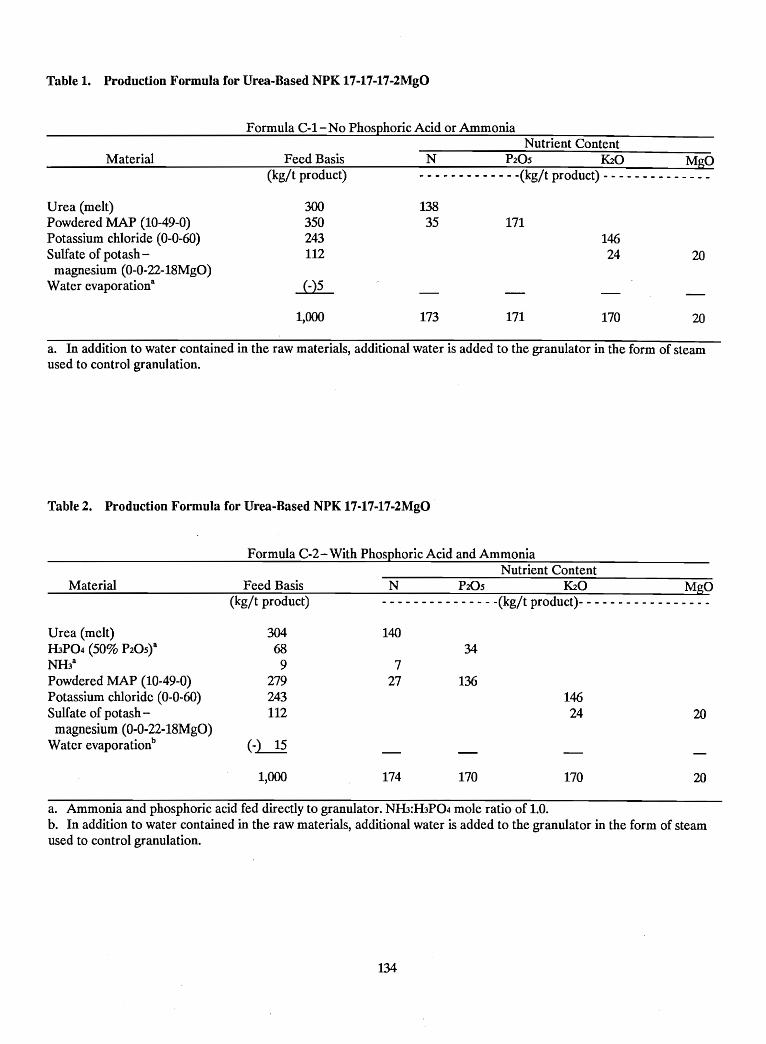
Table 1. Production Formula for Urea-Based NPK 17-17-17-2MgO
Formula C-l- No Phosphoric Acid or AmmoniaNutrient Content
2014624
171
N P20S K20 MgO- - - - - - - - - - - - -(kg/t product) - - - - - - - - - - - - -
13835
300350243112
Feed Basis(kg/t product)
Material
Urea (melt)Powdered MAP (10-49-0)Potassium chloride (0-0-60)Sulfate of potash -
magnesium (0-0-22-18MgO)Water evaporation8
1,000 173 171 170 20
a. In addition to water contained in the raw materials, additional water is added to the granulator in the form of steamused to control granulation.
Table 2. Production Formula for Urea-Based NPK 17-17-17-2MgO
Formula C-2-With Phosphoric Acid and AmmoniaNutrient Content
Material Feed Basis(kg/t product)
N P20S K20 MgO- - - - - - - - - - - - - - -(kg/t product)- - - - - - - - - - - - - - - - -
140Urea (melt)H3P04 (50% P20StNH38
Powdered MAP (10-49-0)Potassium chloride (0-0-60)Sulfate of potash -
magnesium (0-0-22-18MgO)Water evaporationb
304689
279243112
(-~
727
34
13614624 20
1,000 174 170 170 20
a. Ammonia and phosphoric acid fed directly to granulator. NH3:H3P04 mole ratio of 1.0.b. In addition to water contained in the raw materials, additional water is added to the granulator in the form of steamused to control granulation.
134
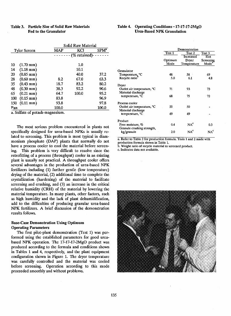
Table 3. Particle Size of Solid Raw MaterialsFed to the Granulator
Table 4. Operating Conditions-17-17-17-2MgOUrea-Based NPK Granulation
Solid Raw Material
10 (1.70 mm) 1.014 (1.18 mm) 10.120 (0.85 mm) 40.0 37.228 (0.60 mm) 8.2 67.0 63.335 (0.43 mm) 18.7 83.2 80.248 (0.30 mm) 38.3 92.2 90.665 (0.21 mm) 64.7 100.0 95.2100 (0.15 mm) 83.8 96.9150 (0.11 mm) 93.8 97.8Pan 100.0 100.0a. Sulfate of potash-magnesium.
Base-Case Demonstration Using OptimumOperating Parameters
The first pilot-plant demonstration (Test 1) was performed using the established parameters for good ureabased NPK operation. The 17-17-17-2MgO product wasproduced according to the formula and conditions shownin Tables 1 and 4, respectively, and the plant equipmentconfiguration shown in Figure 1. The dryer ternperaturewas carefully controlled and the material was cooledbefore screening. Operation according to this modeproceeded smoothly and without problems.
The most serious problem encountered in plants notspecifically designed for urea-based NPKs is usually related to screening. This problem is most typical in diammonium phosphate (DAP) plants that normally do nothave a process cooler to cool the material before screening. This problem is very difficult to resolve since theretrofitting of a process (throughput) cooler in an existingplant is usually not practical. A throughput cooler offersseveral advantages in the production of urea-based NPKfertilizers including (1) further gentle (low temperature)drying of the material, (2) additional time to complete thecrystallization (hardening) of the material to facilitatescreening and crushing, and (3) an increase in the criticalrelative humidity (CRH) of the material by lowering thematerial temperature. In many plants, other factors, suchas high humidity and the lack of plant dehumidification,add to the difficulties of producing granular urea-basedNPK fertilizers. A brief discussion of the demonstrationresults follows.
DemonstrationTest 1 Test 2 Test 3
Increased HotOptimum Dryer Screening
Mode Temperature Modea
GranulatorTemperaturet>°C 48 58 69Recycle ratio 5.0 6.1 4.8
DryerOutlet air temperature, °C 71 93 73Material discharge
temperature, °C 68 75 72
Process coolerOutlet air temperature, °C 55 50Material discharge
temperature, °C 49 49
ProductFree moisture, % 0.4 NA
c0.3
Granule crushing strength,NA
cNA
ckg/granule 2.0
a. Refer to Table 2 for production formula. Tests 1 and 2 made withproduction formula shown in Table 1.b. Weight ratio of recycle material to screened prod\.lct.c. Indicates data not available.
- - - - - - - (% retained)- - - - - - -MAP KCI SPMaTyler Screen
135
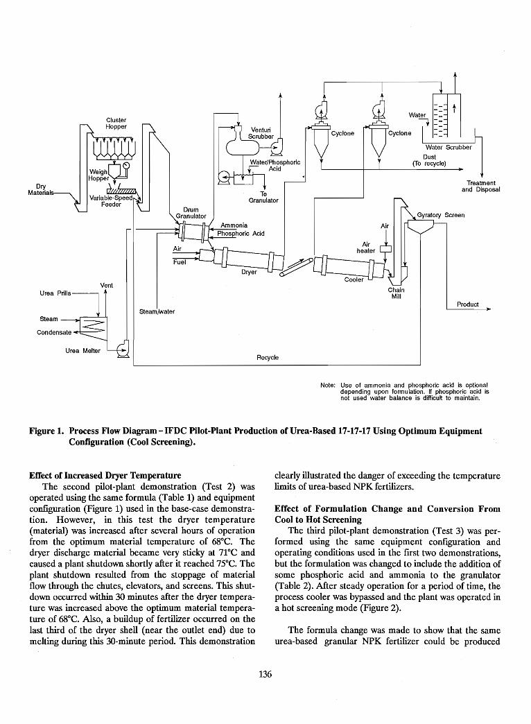
t
Product
Treatmentand Disposal
Water Scrubber
Dust(To recycle)
Water --
~ ==
ChainMill
Cyclone
ToGranulator
AmmoniaPhosphoric Acid
DrumGranulator
Steam/Nater
Vent
ClusterHopper
w~H~~~~rWVariabre:~
Feeder
DryMaterials
Urea MelterRecycle
Note: Use of ammonia and phosphoric acid is optionaldepending upon formulation. If phosphoric acid isnot used water balance is difficult to maintain.
Figure 1. Process Flow Diagram-IFDC Pilot-Plant Production of Urea-Based 17-17-17 Using Optimum EquipmentConfiguration (Cool Screening).
Effect of Increased Dryer TemperatureThe second pilot-plant demonstration (Test 2) was
operated using the same formula (Table 1) and equipmentconfiguration (Figure 1) used in the base-case demonstration. However, in this test the dryer temperature(material) was increased after several hours of operationfrom the optimum material temperature of 68°C. Thedryer discharge material became very sticky at 71°C andcaused a plant shutdown shortly after it reached 75°C. Theplant shutdown resulted from the stoppage of materialflow through the chutes, elevators, and screens. This shutdown occurred within 30 minutes after the dryer temperature was increased above the optimum material temperature of 68°C. Also, a buildup of fertilizer occurred on thelast third of the dryer shell (near the outlet end) due tomelting during this 3O~minute period. This demonstration
clearly illustrated the danger of exceeding the temperaturelimits of urea-based NPK fertilizers.
Effect of Formulation Change and Conversion FromCool to Hot Screening
The third pilot-plant demonstration (Test 3) was performed using the same equipment configuration andoperating conditions used in the fust two demonstrations,but the formulation was changed to include the addition ofsome phosphoric acid and ammonia to the granulator(Table 2). After steady operation for a period of time, theprocess cooler was bypassed and the plant was operated ina hot screening mode (Figure 2).
The formula change was made to show that the sameurea-based granular NPK fertilizer could be produced
136
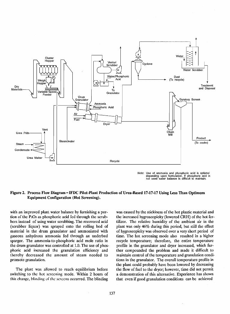
tWater --
~ ==Water Scrubber
Product
(To cooler)
Treatmentand Disposal
Dust(To recycle)
ChainMill
Cyclone
ToGranulator
·DrumGranulator
SteamINater
Vent
ClusterHopper
w~H~~g~rQjVanab~!~
Feeder
DryMaterials
Urea MelterRecycle
Note: Use of ammonia and phosphoric acid is optionaldepending upon formulation. If phosphoric acid isnot used water balance is difficult to maintain.
Figure 2. Process Flow Diagram-IFDC Pilot-Plant Production of Urea-Based 17-17-17 Using Less Than OptimumEquipment Configuration (Hot Screening).
with an improved plant water balance by furnishing a portion of the P20S as phosphoric acid fed through the scrubbers instead of using water scrubbing. The recovered acid(scrubber liquor) was sprayed onto the rolling bed ofmaterial in the drum granulator and ammoniated withgaseous anhydrous ammonia fed through an underbedsparger. The ammonia-to-phosphoric acid mole ratio inthe drum granulator was controlled at 1.0. The use of phosphoric acid increased the granulation efficiency andthereby decreased the amount of steam needed topromote granulation.
The plant was allowed to reach equilibrium beforeswitching to the hot screening mode. Within 2 hours ofthis change, blinding of the screens occurred. The blinding
was caused by the stickiness of the hot plastic material andthe increased hygroscopicity (lowered eRR) of the hot fertilizer. The relative humidity of the ambient air in theplant was only 46% during this period, but still the effectof hygroscopicity was observed over a very short period oftime. The hot screening mode also resulted in a higherrecycle temperature; therefore, the entire temperatureprofile in the granulator and dryer increased, which further compounded the problem and made it difficult tomaintain control of the temperature and granulation conditions in the granulator. The overall temperature profile inthe plant could probably have been lowered by decreasingthe flow of fuel to the dryer; however, time did not permita demonstration of this alternative. Experience has shownthat even if good granulation conditions can be achieved
137
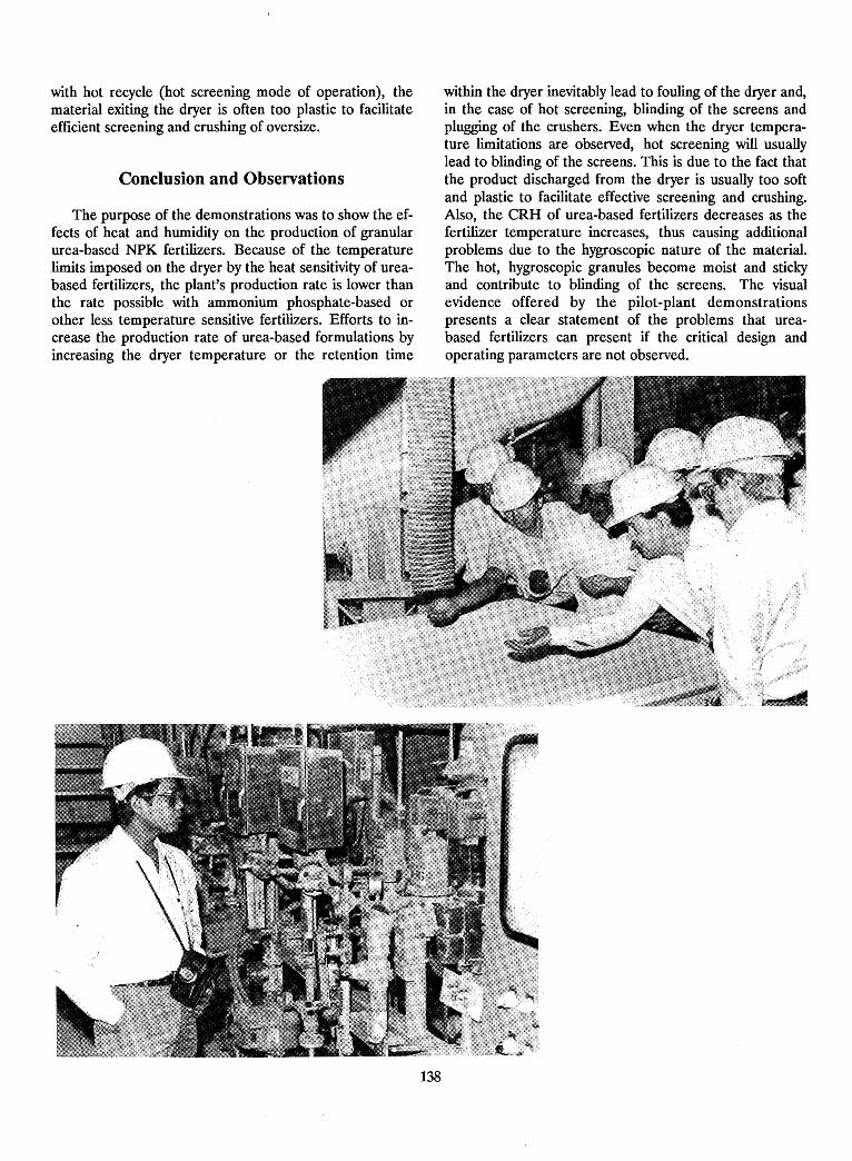
with hot recycle (hot screening mode of operation), thematerial exiting the dryer is often too plastic to facilitateefficient screening and crushing of oversize.
Conclusion and Observations
The purpose of the demonstrations was to show the effects of heat and humidity on the production of granularurea-based NPK fertilizers. Because of the temperaturelimits imposed on the dryer by the heat sensitivity of ureabased fertilizers, the plant's production rate is lower thanthe rate possible with ammonium phosphate-based orother less temperature sensitive fertilizers. Efforts to increase the production rate of urea-based formulations byincreasing the dryer temperature or the retention time
within the dryer inevitably lead to fouling of the dryer and,in the case of hot screening, blinding of the screens andplugging of the crushers. Even when the dryer temperature limitations are observed, hot screening will usuallylead to blinding of the screens. This is due to the fact thatthe product discharged from the dryer is usually too softand plastic to facilitate effective screening and crushing.Also, the CRH of urea-based fertilizers decreases as thefertilizer temperature increases, thus causing additionalproblems due to the hygroscopic nature of the material.The hot, hygroscopic granules become moist and stickyand contribute to blinding of the screens. The visualevidence offered by the pilot-plant demonstrationspresents a clear statement of the problems that ureabased fertilizers can present if the critical design andoperating parameters are not observed.
138
Pilot-Plant Demonstration of TVA Pipe-Cross ReactorTechnology for the Production of Urea-Based 17-17-17
B. w. Curtis l
Introduction
The melt granulation pilot plant at TVA's National Fertilizer and Environmental Research Center (NFERC) wasoperated on September 25, 1990, as part of the IFDCworkshop on Urea-Based NPK Plant Design and Operating Alternatives. The plant was operated at a productionrate of 454 kg/h to produce a granular 17-17-17-3S-2MgOproduct. The purpose of the operation was to demonstratemelt granulation of a urea-based NPK using the pipecross reactor/drum granulator reaction system. A flowdiagram of the TVA process is shown in Figure 2, page 54(B. R. Parker et al.).
Plant Operation
Operation with two formulations was demonstratedone used sulfate derived from sulfuric acid and the otherused solid ammonium sulfate as the sulfate source. Theformulations and typical operating conditions are shown inTables 1 and 2. The particle-size distribution of the solidraw materials fed to the granulator is given in Table 3.
General Observations
The plant operation produced the following observations that may be useful to those comparing a meltprocess using a pipe-cross reactor with a slurry or steamgranulating process.
Advantages
• A generally lower recycle ratio can be obtained withthe melt-type process than with the alternativeprocesses.
• Less drying is required with the melt process.
• Startup and shutdown of a pipe-cross reactor areboth quick and easy compared to these operationswith a tank-type preneutralizer.
Table 1. Formulations for Urea-Based17-17-17-3S-2MgO
Feeds to pipe-cross reactorGaseous ammonia 41 24Phosphoric acid (54% P20S) 315 315Sulfuric acid (92% H2SO4) 50 0
Feeds to granulatorGaseous ammonia 16 16Urea microprills (46% N) 270 270Kieserite (26% MgO) 76 76Potassium chloride
(60% K20) 283 283Ammonium sulfate (20% N) 0 63
The pipe-cross reactor used in the demonstration wasabout 1.8 m long and 3.8 cm in diameter. It was constructed of Hastelloy C-276. The melt distributor was asingle flood-jet spray nozzle. The nozzle's wide angle andlow impact velocity resulted in a very good spray patternand lower recycle requirements. Operation of the pipecross reactor was satisfactory with either formulation.However, more heat of reaction was produced, and thus,less drying was required, when using the formulation containing sulfuric acid (Formula A). An advantage of usingsolid ammonium sulfate is a lower recycle ratio because ofless liquid phase in the drum granulator. The use ofmicroprilled urea avoided the need for crushing the ureabefore feeding to the process. Microprilled or crushedurea is preferred over standard prills to decrease thevisibility of urea particles in the NPK granule structure.
1. Research Chemist, Tennessee Valley Authority (IVA)-United
States.
139
Material
Formula A Formula BUsing Using
Sulfuric AmmoniumAcid Sulfate
- - - - - - - (kg/t) - - - - - -
Table 2. Typical Operating Conditions for theProduction of Granular 17-17-17-3S-2MgO
Condition Formula A FormulaB
Melt NH3:H3P04 mole ratio 0.6 0.6Product NH3:H3P04
mole ratio 1.0 1.0Pipe-cross reactor
Melt temperature atdischarge, °C 143 121
GranulatorRecycle-to-product ratio 2 1Product discharge
temperature,oC 71 68Product water content,
% (AOAC) 2.0 No dataNH3 evolution, % of total
NH3 fed 3 3Dryer
Inlet air temperature, °C 110 110Product discharge
temperature,oC 69 69Screened product
Moisture, % 1.1 No dataGranule crushing strength,
kg/granule 2.8 1.9
Table 3. Particle-Size Distribution of Solid Raw Materials.
Disadvantages
• In general, a more irregularly shaped granule isformed with the melt process.
• With the melt process, it may be difficult to uniformlyincorporate large quantities of potash or other solidmaterials into the granule structure because the duration of the melt (liquid) phase is limited.
• When producing urea-based grades, the high melt temperature may cause excessive melting of the urea andthus make it more difficult to control the liquid phasein the granulator.
Tyler Mesh
10 (1.7 mm)12 (1.4 mm)16 (1.0 mm)20 (0.85 mm)28 (0.60 mm)35 (0.43 mm)Pan
Urea Ammonium PotassiumMicroprills Sulfate Chloride Kieserite- - -- - - - - - - - - - - - - - - - - - (% retained on indicated mesh) - - - - - - - - - - - - - - - - - - - - -
1.2 5.3 1.75.8 7.7 3.9
39.4 17.1 19.662.7 23.0 34.392.9 30.2 62.1 19.998.6 34.8 77.7 40.3
100 100 100 100
140
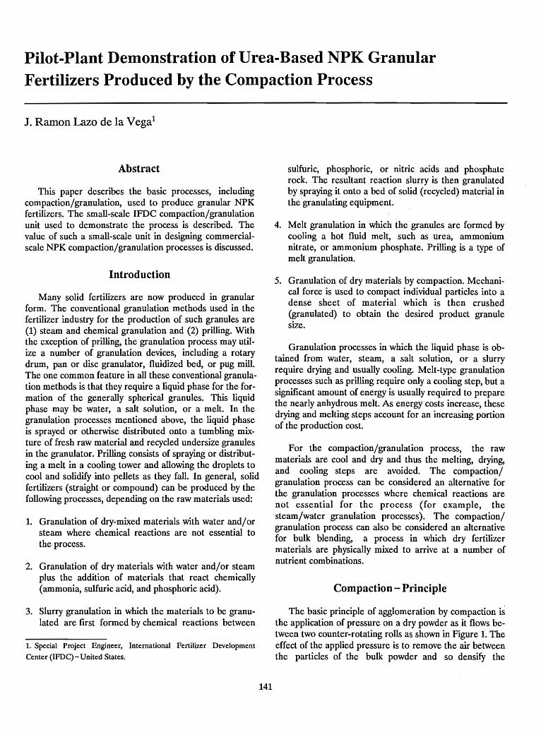
Pilot-Plant Demonstration of Urea-Based NPK GranularFertilizers Produced by the Compaction Process
J. Ramon Lazo de la Vegal
Abstract
This paper describes the basic processes, includingcompaction/granulation, used to produce granular NPKfertilizers. The small-scale IFDC compaction/granulationunit used to demonstrate the process is described. Thevalue of such a small-scale unit in designing commercialscale NPK compaction/granulation processes is discussed.
Introduction
Many solid fertilizers are now produced in granularform. The conventional granulation methods used in thefertilizer industry for the production of such granules are(1) steam and chemical granulation and (2) prilling. Withthe exception of prilling, the granulation process may utilize a number of granulation devices, including a rotarydrum, pan or disc granulator, fluidized bed, or pug mill.The one common feature in all these conventional granulation methods is that they require a liquid phase for the formation of the generally spherical granules. This liquidphase may be water, a salt solution, or a melt. In thegranulation processes mentioned above, the liquid phaseis sprayed or otherwise distributed onto a tumbling mixture of fresh raw material and recycled undersize granulesin the granulator. Prilling consists of spraying or distributing a melt in a cooling tower and allowing the droplets tocool and solidify into pellets as they fall. In general, solidfertilizers (straight or compound) can be produced by thefollowing processes, depending on the raw materials used:
1. Granulation of dry-mixed materials with water and/orsteam where chemical reactions are not essential tothe process.
2. Granulation of dry materials with water and/or steamplus the addition of materials that react chemically(ammonia, sulfuric acid, and phosphoric acid).
3. Slurry granulation in which the materials to be granulated are frrst formed by chemical reactions between
1. Special Project Engineer, International Fertilizer Development
Center (lFDC) - United States.
141
sulfuric, phosphoric, or nitric acids and phosphaterock. The resultant reaction slurry is then granulatedby spraying it onto a bed of solid (recycled) material inthe granulating equipment.
4. Melt granulation in which the granules are formed bycooling a hot fluid melt, such as urea, ammoniumnitrate, or ammonium phosphate. Prilling is a type ofmelt granulation.
5. Granulation of dry materials by compaction. Mechanical force is used to compact individual particles into adense sheet of material which is then crushed(granulated) to obtain the desired product granulesize.
Granulation processes in which the liquid phase is obtained from water, steam, a salt solutimi, or a slurryrequire drying and usually cooling. Melt-type granulationprocesses such as prilling require only a cooling step, but asignificant amount of energy is usually required to preparethe nearly anhydrous melt. As energy costs increase, thesedrying and melting steps account for an increasing portionof the production cost.
For the compaction/granulation process, the rawmaterials are cool and dry and thus the melting, drying,and cooling steps are avoided. The compaction/granulation process can be considered an alternative forthe granulation processes where chemical reactions arenot essential for the process (for example, thesteam/water granulation processes). The compaction/granulation process can also be considered an alternativefor bulk blending, a process in which dry fertilizermaterials are physically mixed to arrive at a number ofnutrient combinations.
Compaction - Principle
The basic principle of agglomeration by compaction isthe application of pressure on a dry powder as it flows between two counter-rotating rolls as shown in Figure 1. Theeffect of the applied pressure is to remove the air betweenthe particles of the bulk powder and so densify the
Figure 1. Diagram of Pressure-Roll CompactionPrinciple.
Pilot-Plant Demonstration ofCompaction/Granulation Process
Description of ProcessThe IFDC Pilot Plant (Figure 2) was configured to
simulate a commercial plant using the compaction/granulation process. The grade produced for thedemonstration is a 11-22-22. The raw material formulationis shown in Table 1. The small-scale IFDCcompaction/granulation unit provides very useful preliminary data on the compaction of a number of solidmaterials and mixtures, including nonfertilizer materials.The unit, however, does have its limitations. Because of itssmall size, sufficient pressure cannot be developed to successfully compact some materials, such as straight ammonia sulfate which requires a pressure equivalent toabout 10 tonnes/cm of roll width. Nevertheless, the unitprovides basic screening-type data, which complementlarger scale testing that is often needed for the design andoptimization of commercial-scale units.
Commercial fertilizer companies located in tropicalcountries claim that for production of urea-based NPKs bythe compaction process the urea content in the formulationshould be kept below 30% to (1) keep product qualityunder control and (2) be able to routinely return therecycle material to the compactor. Once the material hasbeen screened, the rmes and crushed oversize (recyclematerial) contain rme urea dust that picks up moisturevery easily. This moist material sticks to the bucketelevators, chutes, and inside the compactor's feed system.Some companies located in the tropics may be able toproduce a 15-15-15 grade containing about 10% urea butreport having difficulty producing a 19-19-19 grade containing about 25% urea.
+-Pressure
CompactedSheet (Flake)
Material
•
Producing granular urea-based NPK fertilizers by thecompaction process presents more difficulties than doesthe production of ammonium phosphate-based productsby the compaction/granulation processes. This is becauseof the hygroscopicity of urea and the low critical relativehumidity and increased plasticity of fertilizer mixtures containing urea.
material. This densification causes extremely close contactbetween individual particles and the formation of a verydense, strong flake (sheet) in which the forces holding theparticles together may be molecular forces of attraction(van der Waals), adsorption forces, solid bridges, ormechanical interlocking. The formation of solid flakes, orsheets, by such a roll-pressing process using smooth, corrugated, or waffle-surface rolls is normally referred to aspressure-roll compaction. The reduction of the flakes to atypical granular size of 1-4 mm by crushing and screeningis known as granulation; thus, the process is known ascompaction/granulation.
p-.
142
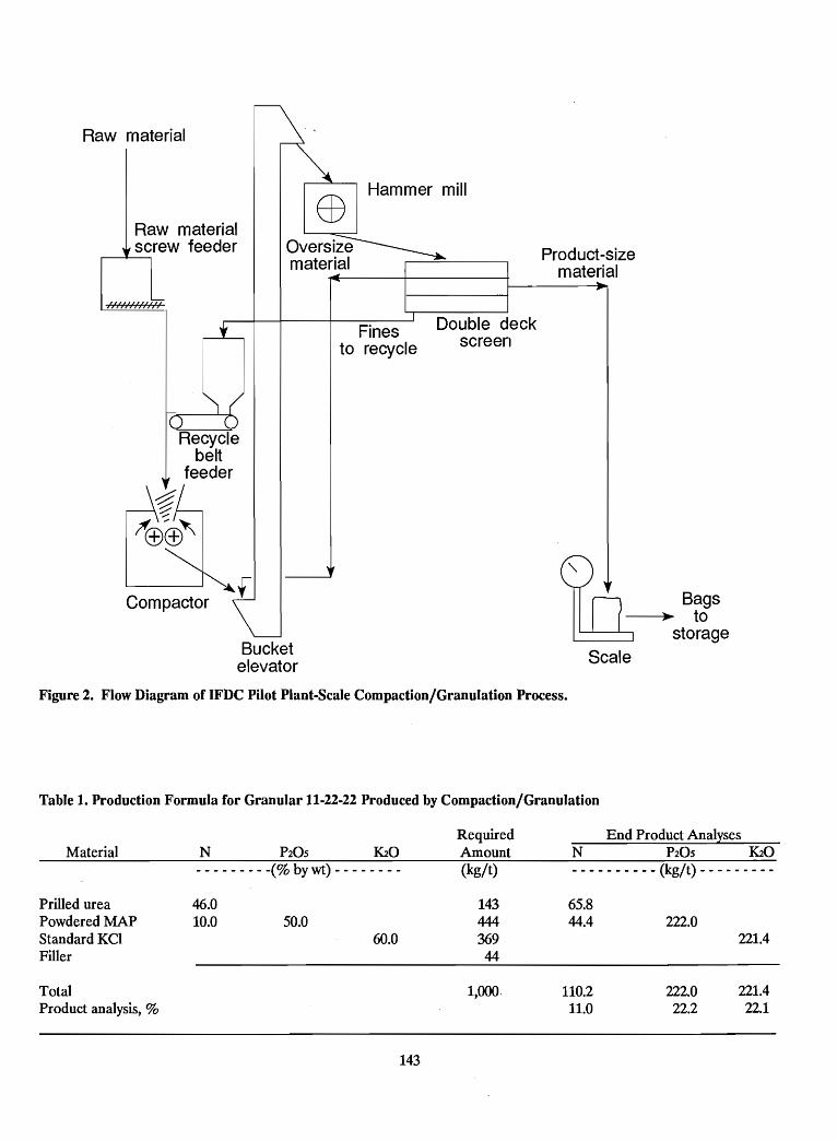
Raw rnaterial
Raw rnaterialscrew feeder
l,','/,'l/,','/,'l
EOHamrner mill
Product-sizematerial
Recyclebelt
feeder
\-:%~~;fffi(±)~
Bucketelevator
Finesto recycle
Double deckscreen
Scale
Bags~ to
storage
Figure 2. Flow Diagram of IFDC Pilot Plant-Scale Compaction/Granulation Process.
Table 1. Production Formula for Granular 11-22-22 Produced by Compaction/Granulation
Material- - - - - - - - -(% by wt) - - - - - - - -
RequiredAmount(kg/t)
End Product AnalysesN ~05 ~o
- - - - - - - - - - (kg/t) - - - - - - - - -
Prilled ureaPowdered MAPStandard KCIFiller
TotalProduct analysis, %
46.010.0 50.0
60.0
143
14344436944
1,000.
65.844.4
110.211.0
222.0
222.022.2
221.4
221.422.1
A screw feeder for the fresh raw materials and a belttype feeder for the recycle material are located above thecompactor. The screw feeder is used to feed a mixture ofurea, monoammonium phosphate (MAP), and potassiumchloride (KCI). The mixture of raw materials and therecycle material discharge into a chute and fall by gravityinto the compactor feed hopper equipped with a mixingdevice (rotating shaft with paddles). The material fromthe hopper is fed to the compactor rolls by a variablespeed screw feeder (auger), forcing the material into theroll nip where the materials are compressed to form asheet (flake) of the product. The IFDC compactor unit isa Ferro-Tech laboratory-scale briquetter/ compactor(Model WP 10-01) that has a roll-over-roll configuration.The rolls are held together by force from a hydrauliccylinder 8.25 cm in diameter. A nitrogen-fIlled accumulator in the system acts as a pressurized reservoir tostore or release oil to one cylinder (roll) in order to maintain a relatively constant separating force for the rolls. Thesystem is pressurized with a manually operated hydraulicpump. The pressure system is capable of a maximum pressure of 10 tonnes on rolls that are 5 cm wide. This is equivalent to a pressing force of 2 tonnes/cm of roll width. Theunit is equipped with variable-speed motors for the rollsand the auger (force feeder). The rolls used for thedemonstration are 12.5 cm in diameter and have acorrugated surface; the depth of corrugation is 1 mm witha pitch of 5 mm. The diameter of the feed auger is 5 cm.
Once the material passes through the rolls and theflake is formed, it flows by gravity into the intake of a
continuous discharge-type bucket elevator. The elevatordischarges the flakes into a hammer mill where they arecrushed and discharged onto a double-deck screen. Thehammer mill is a Prater Industries Model GSHFSI operating at 1,750 rpm.
The double-deck screen separates the hammer-mill discharge material into oversize material, onsize product, andfines (undersize material). The oversize material isrecycled to the hammer mill, and the undersize material isrecycled to the compactor. A Sweco horizontal, vibratingdouble-deck screen is used; it is 122 cm (48 in) indiameter. The screen cloths are 6- and 14-mesh (Tyler)Type 316 stainless steel. The product collected is in theparticle size range of minus 3.35 plus 1.18 mm.
Conclusion
The pilot plant-scale compaction/granulation unit usedby IFDC provides a useful means for performing a preliminary assessment of the compaction characteristics of individual fertilizer materials and mixtures. The unit is alsoused to prepare small quantities (typically 50 kg-500 kg) ofexperimental fertilizer products used for agronomic trials.This combination of preliminary engineering andagronomic data provides a basis for the logical and stepwise development of new or modified fertilizer products.
144
Questions and AnswersAgronomic Session
QuestionWhat are the agronomic differences between nitrogen (N)coming from urea and ammonium nitrate and otherammonium salts?
Answer (B. H. Byrnes, IFDC)Generally there is no agronomic difference if the sourcesare used judiciously. While nitrate forms are not suitablefor flooded rice, the ammonium forms (including urea)are transformed by nitrification to nitrate. Ammonium uptake by plants (other than flooded rice) is normally only asmall amount because nitrification is rapid and ammonium, as a cation, has limited mobility in soils. Nitrateis much more mobile, moving with the soil water to roots.The only notable exceptions to the lack of differences is ifan ammonium source, particularly urea, is not incorporated into the soil and weather conditions cause it tohydrolyze on the soil surface leading to ammonia volatilization. Also, ammonium sulfate leads to soil acidificationmore than nitrate forms or urea.
QuestionWill urea supergranules or compacted fertilizers meet therequirements of "slow release fertilizers?"
Answer (B. H. Byrnes, IFDC)Deep point placement of urea (with supergranules) appears to not only reduce losses through ammoniavolatilization and denitrification in flooded soils, but italso delays N availability to the rice plant. This is thoughtto be due to its spatial separation from early root growthand to its development of high ammonia concentrationsthat may temporarily inhibit root growth into the placement zone. Since urea is soluble, supergranules would notbe considered a slow-release fertilizer, but they may beconsidered a delayed availability form of managementwhich is often desirable.
QuestionWhat exactly is "urea sulfur" and how is it produced?
145
Answer (D. K. Friesen, IFDC)Urea sulfur (36-0-0-20S) was a product produced by Cominco Ltd. (Canada) containing 20% fmely divided elemental S dispersed throughout the urea prills or granules. It ismade by combining streams of molten urea and moltensulfur and mixing them above their melting points andthen prilling the melt.
Answer (J. J. Schultz, IFDC)Another urea-sulfur product was recently developed byNSM of the Netherlands (now Norsk Hyd~ BelgiumS.A.). This product· is called UREAS. It is ahomogeneous granular mixture of urea and ammoniumsulfate containing 40% N and 5% S. It is produced in afluidized bed-type granulation process developed by NSM.
QuestionHow is sulfur mixed with TSP?
Answer (D. K. Friesen, IFDC)Finely divided elemental sulfur is added along with phosphoric acid during the acidulation of phosphate rock in theTSP process. The elemental sulfur slurry can be preparedby wet grinding sulfur or by spraying molten sulfur into arapidly stirred tank of phosphoric acid. Our test productcontained 16% S (P:S = 1) but the concentration can beadjusted to suit a particular market.
QuestionUrea suffers from volatilization. If this loss of nitrogen is apredictable percentage, it is only a matter of economics.But volatilization is not predictable, and the crop mayeither have too much or too little nitrogen. How can thisproblem be overcome?
Answer (B. H. Byrnes, IFDC)Nitrogen losses through ammonia volatilization are noteasily predicted, since volatilization is dependent onseveral climatic and soil factors. If rainfall occurs, the ureais dissolved and moves into the soil. With no rainfall,
ammonia volatilization depends on the hydrolysis rate ofthe urea, ability of the soil to absorb ammonium, the pHof the soil and its buffering capacity, and wind speed andtemperature. Caution should be used in extrapolating urealoss measurements to a urea-PK product for three mainreasons:
1. Research has shown that urea phosphates are not assusceptible to losses as urea alone because a lower pHdevelops in the microzone around the hydrolyzinggranule.
2. The amount of urea at any granule site is low so theammonium absorption capability of the soil may not beexceeded.
3. The P and K constituents are not well utilized whenleft on the soil surface, so urea-PKs should be incorporated if at all possible, leading to little ammonialoss.
QuestionYou indicated that when phosphate rock (PR) is compacted with urea, the P20S becomes more soluble. Wasthis tested with neutral ammonium citrate solution?
Answer (S. H. Chien, IFDC)The beneficial effect of urea on PR dissolution takes placeonly in the soil. When urea hydrolyzes in soil, the increasein soil pH may result in hydrolysis of soil organic matterwhich in turn complexes with Ca+2 released from PR dissolution. Because Ca+2 concentration in the soil solution isdecreased, this enhanced further PR dissolution.
QuestionDr. Chien showed slides evaluating results of compactedTSP plus urea plus KCl. I was always told you could notmix TSP and urea. Please comment.
Answer (S. H. Chien, IFDC)It is true that urea is incompatible with TSP in compaction. But here we compact PR + TSP + urea rather thanurea + TSP alone. Normally, we fix the P20S ratio ofPR:TSP at 50:50. Since P20S of PR is about 30% and TSPis about 48%, there are many PR particles that can blockthe interaction between TSP and urea so that formation ofthe adduct is reduced. Additional KCI may further reducethe adduct formation by diluting the concentrations ofTSP and urea. Al.so, the quality of the TSP (for example,free acidity and moisture content) has a major influenceupon its compatibility with urea. Therefore, one should becautious and it is important to carefully evaluate each particular source of TSP before committing to its commercialuse with urea.
146
QuestionIn the United States, are the farmers satisfied using NPKswith prices higher than straight materials? How about indeveloping countries?
Answer (J. J. Schultz)The cost of fertilizer represents anywhere from about 10%to 20% of the cash cost of production in the United Statesdepending upon the crop. The farmer does not object topaying a bit more for a fertilizer provided his total cost ofproduction does not increase. Major production costs inthe United States are interest, fuel, pest control chemicals,and labor; therefore, decisions are not made solely on thecost of the fertilizer component. A multinutrient fertilizer(homogeneous granular or blend), although costing morethan a straight material, may save considerably on fuel andlabor required for application.
In many developing countries the situation is often quitedifferent. Many times fertilizer may represent 60%-80%of the cash cost of production. In this case, the farmerwould be very reluctant to pay more for a granularproduct or any other form of fertilizer that costs morethan the lowest cost straight material.
QuestionMr. Schultz, your comments are significantly recognized inIndonesia because all Indonesian fertilizer companies areproducing single nutrient fertilizers that are subsidized bythe Government. If a company wants to manufacture acompound fertilizer, say DAP or an NPK, it will not besubsidized and the price will be much higher comparedwith a single nutrient fertilizer or a self-mixed (blended)fertilizer made from single nutrient materials. What areyour comments?
Answer (J. J. Schultz)Your point is understood. Any type of subsidy programhas its share of flaws. In this case, the subsidy system inIndonesia inhibits change from the subsidized straightmaterials - urea, ammonium sulfate, and TSP. This maybe good, then again it encourages overuse of these cheap(subsidized) fertilizers which, in the long run, will be harmful not only to the soil and environment but also to theeconomy of the country. This is one reason why currentlythere is much pressure worldwide to decrease subsidies,especially on agricultural inputs such as fertilizer andpesticides.
QuestionWhat kind of equipment is used for coating urea withpolymers?
Answer (J. H. Detrick, Pursell Industries)The two reactive monomers - (1)isocyanate and (2) apolyester polyol containing an amine catalyst - arepumped through separate lines to a series of alternatespray nozzles located in a rotary drum. The preheated cascading urea granules pass under these spray nozzles sothat the two liquid monomers are applied in layers ontothe granule surface. The rubbing action of one granuleagainst the next spreads the liquid monomers as theycopolymerize to form a solid coating. The thickness of thecoating is controlled by the fluid flow rates, urea flow rate,and the number of nozzles used. In general, the coating ona nominal 2.5 mm diameter granule is about 25 micronsthick and represents about 6% of the coated productweight.
QuestionHave you made agronomical tests to compare the efficiency of different controlled-release nitrogen fertilizers(for example, SCU, UF, IBDU, and melamine) and whatkind of results do you have? Can you compare UF,IBDU, and melamine as controlled release fertilizers? Doyou have any experience with DCD or correspondingproducts (nitrification inhibitors)?
Answer (J. H. Detrick, Pursell Industries)The graph shown on page 10 (Figure 1) illustrates our experience with a number of controlled-release nitrogen fertilizers applied on turfgrass.
QuestionHow do you see the market for controlled-release fertilizer products in the future?
Answer (J. H. Detrick, Pursell Industries)Controlled-release fertilizers, particularly controlledrelease nitrogen products, will continue to grow in the noncrop sector (for example, turfgrass) at an annual rate of3%-5%, but this rate can turn down in a sluggisheconomy. The use on agricultural crops will be limited tothose of high cash value, such as ornamental horticulturein the United States where land values are fromUS $10,000 to US $30,000 per acre, or on row crops, suchas strawberries grown in sandy soil under black plasticmulch (tendency to leach, high soil temperature, and onetime fertilizer application). The polymer-coating technology can also potentially be applied to certain pesticideswhere extended pesticide effect is desired and waterrunoff and chemical leaching are concerns.
147
Questions and AnswersNPK Plant Design and Operation
QuestionAs per the chart on percent product change (after makinga raw material feed change) versus time for differentrecycle-to-product ratios, it is seen that it takes 10 hoursfor change in the case of a recycle ratio of 6 (refer toFigure 4 in Appendix). In a plant with, say, 40 tph production capacity, what will happen to the production(400 tonnes of off-grade material) during this period. Atthis rate, before a correct adjustment is attained, a largeamount of off-specification product would be produced. Iwould appreciate your comments on this.
Answer (J. J. Schultz, IFDC)You are correct; it takes a long time· for a change in feedto show up in the product. That is why good control andmanagement of the process are essential. The flow instruments must work properly and be constantly checked toensure that the indicated readings are correct. If your instruments are unreliable, there is no way that you can adjust them to correct an off-specification product. Therefore, we must start with equipment that can be easilychecked on a running basis. This is the reason why I advocate the batch-type feed system. Every batch can becarefully checked and cross checked simply by using a stopwatch to time the continuous streamout feed rate of aknown weight of material, say 5 tonnes. On a weekly basis,or more frequently, a test weight set can be used to doublecheck the accuracy of the batch weighing scale. Thesecheck weights can also be installed in such a way that thebatch scale can be checked each shift in just a few minutesusing a test weight platform and cable attachment system.If continuous weigh belt-type feeders are used, theyshould be installed in such a way that their output can bechecked at least twice a shift by diverting the feed to a testscale unit. This, of course, is difficult to do and labor intensive. The answer to your question, then, boils down to thefact that large amounts of off-specification product will beproduced if the feed rates are not precisely controlled.Once the feed rate is off, it takes a long time even underideal circumstances to correct the impact it has on theproduct.
148
QuestionAs we saw from the graph, an adjustment made to controlthe nutrient content will show up only after a period oftime fixed by the recycle-to-produce ratio (throughput andretention time). How often would you suggest samplingthe end product for process control purposes?
Answer (J. J. Schultz, IFDC)In a typical NPK plant operating at a 3:1 recycle-toproduct ratio, about 75% of the change in feed composition will show up in the product after about 4 hours. Forthe purpose of checking the process control, I suggest thata change in the process feed rates be made only after comparing the analytical results of two consecutive samplescomposited on 3D-minute intervals over a period of4 hours, beginning 4 hours after making the change infeed rate. Making a change on anything less than a 4-hourcomposite of the final product would be quite meaningless. This, of course, does not apply to the preneutralizerslurry which may be sampled more frequently. It is important to note that sampling of the fmal product is done tocheck the process performance rather than to serve as aprimary control of the process.
It is important to understand your particular plant and thelag time that it has, not only for different recycle-toproduct ratios but also for different production rates andformulas. Once you know this lag time between feed andproduct, you can use an analytical result to more closelypredict what change should or should not be made. Forexample, a sample taken 2 hours after making a change infeed is useful in estimating the analysis that can be expected 2 hours later. Such samples help establish a meaningful trend and give you an indication of what to expectseveral hours later.
In routine practice, an 8-hour (shift) composite provides areasonably good basis for making a change. It is importantto note that if your scales and meters are workingproperly, there is no need to constantly make feed ratechanges based on product analysis. The problem may be
poor granulation and segregation together with an inadequate sample collection and sample preparation procedure. Keep in mind that, under normal circumstances, thereported analytical result is based on a sample aliquotequivalent to about one two-hundred-millionth of theproduct actually produced during the sample period(assuming 8 hours at 30 tph production rate). This underscores the importance of sample collection andpreparation.
QuestionYesterday we said that in the case of urea-based NPKs,fluidized beds are not advisable for drying service; arethey suitable for cooling service?
Answer (J. J. Schultz, IFDC)A fluidized-bed unit is well suited for cooling provided thematerial is closely sized. This means that a fluidized bedwould not be advisable for the process cooler (beforescreening) but it would be okay for product cooling afterscreening. You may recall that Mr. Ramaswami of NAFCON said that their fluidized bed product cooler causessome problems with excessive entrainment of solids if thescreens should blind and fines pass into the productcooler. Mr. Ramaswami also pointed out the importanceof keeping the relative humidity of the air fed to thefluidized bed cooler low during operation as well as duringshutdowns to avoid wetting and plugging of the air distribution tray. As with all equipment, fluidized beds have theirlimitations, but if properly designed and installed they arevery good for cooling a well-screened product.
QuestionHow much does a granulation pilot plant such as IFDC'scost?
Answer (J. J. Schultz, IFDC)In 1977 the IFDC combination bulk-blending/granulationpilot plant cost US $650,000. This cost includedUS $500,000 for machinery and equipment includingelectrical and instrumentation; US $50,000 for engineering(all done by IFDC); and US $100,000 for fieldconstruction/installation labor and supervision. This costdoes not include the basic pilot plant building which wasalready existing but it does include all structural supportsteel as the pilot plant is freestanding inside the main pilotplant building.
QuestionWhat is the optimum quantity of material that can be fedinto the system using a cluster hopper-type feed system?
Answer (J. J. Schultz, IFDC)Typically a cluster hopper system will have a combinedraw material capacity of 50-60 tonnes divided between 4-6hoppers. In a 3O-tph granulation plant this would translateto a retention time of about 1.5 hours assuming the hoppers are kept reasonably full. A typical batch weighing system can handle 4- to 5-tonne batches. If the dry materialportion of the formula is equivalent to 30 tph, then six5-tonne batches would be prepared every hour, or onebatch every 10 minutes. As indicated earlier by Mr. Mohd.Salleh of FPM, they prefer to weigh more smaller batches(12 per hour) to achieve better mixing of the ingredientsbefore they enter the granulator. Since one can easilyweigh twelve 5-tonne batches per hour, it would be possible to feed the dry raw materials at a rate of about60 tph; this would mean that the cluster hopper retentiontime would be about 30-45 minutes if the hopper is keptbetween 50% and 75% full. This shorter retention time inthe cluster hopper system is preferred for materials thattend to bridge; for example, superphosphate and ammonium sulfate.
QuestionIn the IFDC pilot plant, why are knockers located near theinlet end of the dryer when the buildup seems to occurnear the outlet end?
Answer (J. J. Schultz, IFDC)The pilot plant is used for many duties. In some formulations buildup occurs near the inlet. This is especially truefor NPKs based on single superphosphate. However, asyou noted, with many urea-based NPKs a "melting"phenomenon occurs when drying is nearly completed. Thisleads to sticking and buildup near the outlet; ideally, inthis case the knockers should be located in this potentialsticking zone near the discharge end.
In general, I question the effectiveness of knockers, theyseem to be a good idea but in reality they impart very littlevibration to a heavy (thick) dryer shell and onwardthrough the flights where the buildup actually occurs themost. A more practical method for controlling(minimizing) buildup is to carefully control the temperature profl1e inside the dryer.
QuestionCan a drum granulator and a pug mill replace each other?Are they interchangeable?
Answer (J. J. Schultz, IFDC)If you are referring to agglomeration-type granulation, a
. pug mill is a very good choice as it promotes intimate
149
mixing as well as granulation. A major drawback of a pugmill is that it is difficult to mechanically support spargerslocated beneath the bed of material. To keep the spargersystem simple, steam, water, and ammonia are usually fedthrough the same sparger as there is usually not enoughroom to fix more than one sparger in the bottom of a pugmill. Sometimes the problem with spargers can be partially overcome by injecting ammonia or other materialsinto the pug mill through a number of "injection points"located along the bottom of the pug mill. Another disadvantage of the pug mill is that it requires more power thana rubber panel-lined rotary drum granulator.
In my opinion, the ideal granulation plant, assuming solidsagglomeration, would consist of a pug mill to premix andmoisten all materials (including recycle) followed by arotary drum unit for ammoniation and final granulation.However, if only one granulation device is available, therotary drum unit offers maximum flexibility. I do,however, recommend that the length-to-diameter ratio ofthe rotary drum be at least 3; the longer unit facilitatesgood mixing and distribution of solids and liquids and improved granule formation prior to drying.
QuestionWhat is the maximum quantity (percent) of urea melt thathas been successfully used in commercial plants producingurea-based NPKs?
Answer (J. J. Schultz, IFDC)This is difficult· to answer. I know of some NPK gradesthat contained 30% urea melt but granulation was notgood because the melt solidified too quickly to agglomerate the potash and other solids. TVA produced anNP (28-28-0) grade which was basically a 50/50 mix ofmolten urea and ammonium polyphosphate melt. Themixing of the two melt streams was done in a pug mill andproper placement of the streams (including scrubber liquor) with respect to the recycle was important to obtain ahomogeneous mix.
The amount of urea melt that can be successfully usedvaries quite widely depending upon other sources of liquidphase in the formula and the amount of solids that mustbe incorporated into the granule structure.
QuestionMr. Polo, the ammonia absorbing capacity of H2S04 wasshown to be 34% of the dry basis acid weight in yourtable. Is it believed that the reaction of sulfuric acid andammonia is almost complete and instantaneous; wouldyou enlighten us on this please?
150
Answer (J. R. Polo, IFDC)Yes, the reaction between ammonia and sulfuric acid toform ammonium sulfate is almost complete and instantaneous. In reality some ammonium bisulfate·will also beformed unless a large excess of ammonia is. used, but Iwould not expect this amount of bisulfate to be over onehalf of 1% of the sulfate produced. No reaction is absolutely complete, and this is particularly so in the case ofsulfuric acid which has two hydrogen ions to be replaced.Replacing the frrst hydrogen (forming the bisulfate) isquite easy and fast, while replacing the second one (toform sulfate) takes a little longer and an excess of ammonia. However, as I said before, we can consider thereaction to ammonium sulfate to be complete because ofthe small amount of bisulfate made, and we can considerit to be instantaneous because it is fmished within the timethat the material is in the preneutralizer and in thegranulator. The sulfuric acid reacted in the preneutralizermay form a larger amount of bisulfate because of the excess of acid in this equipment as indicated by its low pH.However, the balance of the ammoniation reaction to sulfate takes place in the granulator. The overall ammoniaabsorbing capacity of H2S04, given as equivalent to 34%of the dry basis acid, is really a round number which is notaffected by the small quantity of bisulfate formed.
Comment (J. J. Schultz, IFDC)It is interesting to note that when relatively large qmintities of sulfuric acid are reacted along with phosphoricacid in a preneutralizer, a very fluid slurry can beproduced at a low moisture content (about 10%-12%) ifthe NH3:H3P04 mole ratio is maintained at about 0.4 (pHof about 2). If the mole ratio is raised to about 1.5 (pH ofabout 6.8), the same slurry becomes quite viscose and thefree water content has to be increased to about 20% ormore to facilitate pumping. The reason for the large difference in fluidity (pumpability) at the two mole ratios(low and high pH) is most likely due to the quantity, size,and shape of the undissolved ammonium phosphate crystals and perhaps partly to the presence of a higher level ofammonium bisulfate at the lower pH.
QuestionHow does one predict the temperature in the granulator ifthe recycle-to-product ratio changes?
Answer (J. R. Polo, IFDC)Particularly in the case of urea-based NPKs in which theuse of a process cooler is strongly recommended, thetemperature of the recycle is typically some 10°-30°Clower than the temperature of the granulator bed(discharge). Under these conditions, and considering that
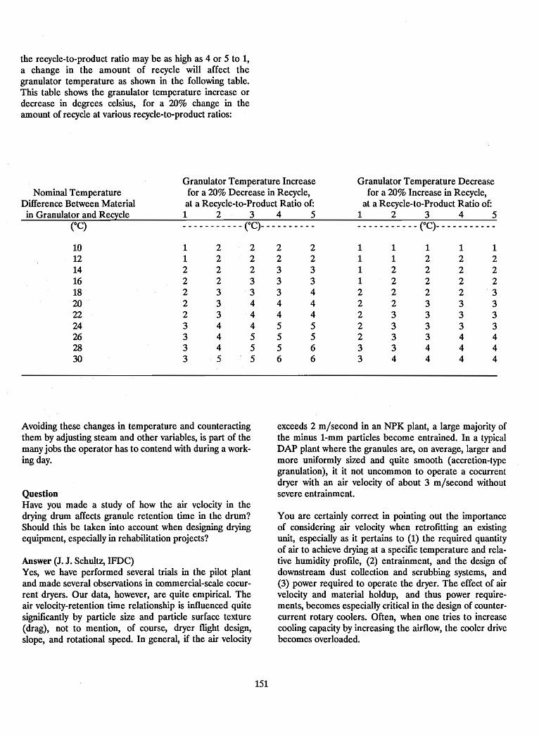
the recycle-to-product ratio may be as high as 4 or 5 to 1,a change in the amount of recycle will affect thegranulator temperature as shown in the following table.This table shows the granulator temperature increase ordecrease in degrees celsius, for a 20% change in theamount of recycle at various recycle-to-product ratios:
Granulator Temperature Increase Granulator Temperature DecreaseNominal Temperature for a 20% Decrease in Recycle, for a 20% Increase in Recycle,
Difference Between Material at a Recycle-to-Product Ratio of: at a Recycle-to-Product Ratio of:in Granulator and Recycle 1 2 3 4 5 1 2 3 4 5
eC)___________ (OC)__________ ___________ (OC)___________
10 1 2 2 2 2 1 1 1 1 112 1 2 2 2 2 1 1 2 2 214 2 2 2 3 3 1 2 2 2 216 2 2 3 3 3 1 2 2 2 218 2 3 3 3 4 2 2 2 2 ·320 2 3 4 4 4 2 2 3 3 322 2 3 4 4 4 2 3 3 3 324 3 4 4 5 5 2 3 3 3 326 3 4 5 5 5 2 3 3 4 428 3 4 5 5 6 3 3 4 4 430 3 5 5 6 6 3 4 4 4 4
Avoiding these changes in temperature and counteractingthem by adjusting steam and other variables, is part of themany jobs the operator has to contend with during a working day.
QuestionHave you made a study of how the air velocity in thedrying drum affects granule retention time in the drum?Should this be taken into account when designing dryingequipment, especially in rehabilitation projects?
Answer (J. J. Schultz, IFDC)Yes, we have performed several trials in the pilot plantand made several observations in commercial-scale cocurrent dryers. Our data, however, are quite empirical. Theair velocity-retention time relationship is influenced quitesignificantly by particle .size and particle surface texture(drag), not to mention, of course, dryer flight design,slope, and rotational speed. In general, if the air velocity
151
exceeds 2 m/second in an NPK plant, a large majority ofthe minus l-mm particles become entrained. In a typicalDAP plant where the granules are, on average, larger andmore uniformly sized and quite smooth (accretion-typegranulation), it it not uncommon to operate a cocurrentdryer with an air velocity of about 3 m/second withoutsevere entrainment.
You are certainly correct in pointing out the importanceof considering air velocity when retrofitting an existingunit, especially as it pertains to (1) the required quantityof air to achieve drying at a specific temperature and relative humidity proftle, (2) entrainment, and the design ofdownstream dust collection and scrubbing systems, and(3) power required to operate the dryer. The effect of airvelocity and material holdup, and thus power requirements, becomes especially critical in the design of countercurrent rotary coolers. Often, when one tries to increasecooling capacity by increasing the airflow, the cooler drivebecomes overloaded.
QuestionRoller mills are used in NSM's urea and ammoniumnitrate granulation plants with more than satisfactoryresults. Are they applicable in conventional NPK andurea-based NPK plants?
Answer (J. J. Schultz, IFDC)Roller mills are good for hard/crisp granules. The moresoft and plastic NPKs often cause the rolls to accumulatea buildup of material and become ineffective.
Some NPK plants using roll-type crushers provide ascrew-like scraper unit to keep the roll surface clean.Given a choice, I would not recommend using a roll-typecrusher in an NPK plant, especially if several formulationsare produced. Some formulas may crush nicely whileothers may be too plastic for reliable performance of thecrusher.
Comment (T. Koivumaki, Kemira Oy)I would like to offer some additional opinions about thegranulation loop; I think we must always keep in mindthree things:
1. Stability of granulation.2. Quality of product.3. Investment cost of the plant.
Remembering these things, in most cases the result is different to that which was presented by Mr. Bolds. We mustalso keep in mind that equipment must work like themanufacturer has promised (performance guarantee).Therefore, I suggest the following:
1. The best way to change granulation away from an "art"is to control the recycle ratio; weighing techniquesprovide a good way for doing this. With recycle controlyou can have as stable granulation conditions as possible and this is needed for the proper functioning ofthe whole granulation loop.
2. If you return crushed granules back to the screen, theroundness of the product is not proper. If you return itto the granulator, granules in the product are moreround. This means that the crusher must work likeplanned (oversizing is needed). We must claim properperformance from the manufacturers of crushers.Also, with proper crusher performance, we can avoidovergranulation problems due to improper crushing.
3. Usually the investment cost is wanted to be as low aspossible; thus we need to use double-deck screens(lower height, lower investment cost, lower operatingcost). You have the possibility to specify what kind ofscreens you buy, arid it is. possible to get inclined
152
double-deck screens which work properly and have theprovision for cleaning both decks. The price of this kindof screen is higher than some double deck screens butthe total investment cost is lower and actually the operation of this kind of screen is easier. If the screen becomes blinded (which is malfunction of the plant), thereare several possibilities to control and prevent this asblinding only seldom happens suddenly. In conclusion,YOlf have to compromise.
Comment (J. J. Schultz, IFDC)I think Mr. Koivumaki's points are all very valid. However,as he points out, there is always a compromise betweenwhat should be done and what is actually done, dependingupon your point of view. An engineer/contractor will oftengo for least frrst cost to ensure securing the contract. Theowner, too, often looks for the lowest first cost. Anoperator (and most enlightened owners) will look forreliability, ease of operation, and minimum downtime. Inshort, a "forgiving" plant that can accommodate upsetswithout causing a shutdown. In the long run, the oftensmall difference in capital cost between an "adequate"plant and an "optimum" plant is usually insignificant andoften lower when measured in terms of dollars per tonneof product and product quality.
Mr. Koivumaki's point on controlled recycle and controlled particle size (surface area) is absolutely correct. Formaintaining equilibrium, every effort should be made toachieve control of the solid phase through efficient screening and crushing which, in turn, will stabilize conditions inthe granulator and make the system very smooth andstable. In short, especially with agglomeration-typegranulation, smooth operation leads to even smootheroperation while mildly upset operation leads to a severallyupset (uncontrollable) operation.
Comment (T. Koivumaki, Kemira)-I completely agree that hot screening is more difficult andunforgiving then cold screening. However, hot screeningin ammonium phosphate- and nitrophosphate-basedNPKs is made quite often because of savings in energy consumption. We could not see this in the IFDC pilot-plantdemonstration of 17-17-17. When the pilot plant wasswitched from cold to hot screening, the fuel flow into thedryer was kept constant which meant that the outlet tern-perature increased from 60° to 70°C and the granule sizedistribution in the granulator changed towards biggergranules and the whole granulation was different to that ofcold screening.
To get a more real picture of hot screening, I think duringthe IFDC pilot-plant demonstration the granulationtemperature should have been kept constant before andafter the change (fuel consumption would have been
smaller). However, there probably would have been difficulties in screening at least in the long run with this kindof screen.
QuestionTo store bulk urea, we would need to have dehumidifiedair. Does this imply using reheated refrigerated air?
Answer (J. J. Schultz, IFDC)Dehumidification is not absolutely necessary for bulk ureastorage if the material is going to be reclaimed for use in agranulation unit. However, to maintain a reasonably dryfloor (for safety and housekeeping reasons) it is good tokeep the bulk storage building as tightly closed as possibleand allow solar heat to warm the building and thusdecrease the relative humidity and minimize crusting ofthe pile. It is also important to maintain a rapid turnoverof product under such undehumidified storage conditionsto minimize deep penetration of moisture into the pile. Inone case that I observed, prilled urea stored under humidconditions for about 8 months was caked very hard due todeep penetration of moisture which made reclaiming very,very difficult.
Bulk urea-based NPKs must, under humid conditions of50% relative humidity or more, definitely be stored in adehumidified area. Heated air may be sufficient, but inmany cases the air must first be chilled to remove some ofits moisture and then reheated to lower the relativehumidity to about 40%-50% as you indicated.
QuestionDoes the oil utilized to ftx kaolin clay on granules have tomatch any particular specifications?
Answer (D. W. Rutland, IFDC)Several types of oils (fuel, motor, lubrication, and blends)have been used for adhering clay conditioners to fertilizerswith varying degrees of success. The oils which seem tobe the most effective on ammonium nitrate-based NPKsare moderately viscous oils (25 to 150 mPa· s) such aslubrication oils. The oils which seem to be the most effective on urea-based NPKs are lubrication and motor oilswith viscosities of around 100-200 mPa· s. Used motor oilsusually have wide variations in viscosity, water content,solids, and poisons (lead, cadmium, barium) and consequently are unsuitable for fertilizer coating. Lightweightoils can be absorbed rather quickly into the granules,whereas heavyweight oils are quite difficult to spray. Typical application rates are 0.2%-0.5% at 40°_60°C.
153
QuestionWhat can be the order of magnitude of crushing strengthfor NPK granules based on agglomeration?
Answer (D. W. Rutland, IFDC)The crushing strength of urea-based NPKs made byagglomeration can vary quite markedly depending on manyfactors including chemical composition, method of production, granule structure, granule porosity, granule size,moisture content, and binder. IFDC measurements of thecrushing strength of urea-based NPKs have ranged from1.0 to 4.0 kg/granule (2.36 to 2.80 mm fraction). Refer toTable 1 in Appendix for typical crushing strength data.
QuestionIFDC usually refers to Tyler sieve. Is this, or U.s. standard, the most widely used worldwide? I understand thatin the United States, the U.S. standard sieve has becomethe official standard per AAPFCO.
Answer (D. W. Rutland, IFDC)IFDC uses the American Society for Testing Materials(ASTM), Specification E-11-81 U.SA. standard sieveseries, which is based on sieve openings in millimeters andmicrons, not sieve numbers. These standard designationscorrespond to the values for test sieve apertures recommended by the International Organization forStandardization (ISO-565). Occasionally, depending onthe audience or client requirements, IFDC will also showthe Tyler, U.S., Market Grade, or Tensil Bolt Clothnumber that most closely matches the sieves shown inmillimeters and/or microns. Some countries use the ISOstandard sieve series, some countries use their ownstandard sieve series, and some countries use othercountry standard sieve series. India has a sieve seriesreferred to as the IS sieve series, which has identicalopenings to the ASTM and ISO sieve series. There arealso French, English, German, Italian, and Russian sieveseries.
QuestionWould you please tell us more about degradation of theliquid amine-based anticaking reagent? What is thesuitable temperature for addition?
Answer (D. W. Rutland, IFDC)Amines are considered as derivatives of ammonia (NH3)by replacing one or more of the hydrogen atoms with alkylgroups. The amine can be primary, secondary, or tertiarydepending on whether one, two, or three of the hydrogen
atoms are replaced. The degradation of an amine resultsin ammonia volatilization. The most volatile amines areusually the low molecular weight formulas. Most primaryand secondary amines must have their hydrogen(s)substituted by high molecular weight groups such as fattyacid alkyl groups to remain nonvolatile. Tertiary aminesare the least volatile; unfortunately, most of the tertiaryamines are quite viscous liquids or even in paste form atroom temperature.
Temperature has a significant effect on the degradation ofamines. Amines are applied at temperatures ranging from30° to 120°C depending on the amine viscosity. It isnormally recommended that a high viscosity amine beheated and used as quickly as possible (low retentiontime) to avoid degradation.
Additionally, the fertilizer temperature is important. Lowtemperature (30°-50°C) fertilizer should be avoidedbecause amines will not adhere well to "cold" granules.Conversely, very high temperature (70°-120°C) may resultin amine degradation.
QuestionAre combinations of various types of anticaking agentsused to increase the anticaking effect or to lower the costof the agent?
Answer (D. W. Rutland, IFOC)Combinations of different types of anticaking agents areusually used to increase effectiveness when compared to asingle type of anticaking agent. This could lower or raisethe cost of the anticaking agent. For example, kaolin clayis not considered to be completely effective for use onammonium nitrate. However, kaolin clay treated with anionic surfactant is considered to be an effective anticakingagent for ammonium nitrate. Therefore, possibly asmaller dosage of kaolin clay could be used, therebyreducing the cost. However, the additional cost of thesurfactant could offset the cost savings in kaolin.
QuestionDo you think dehumidified storage is necessary for storingbulk NPK products that have been conditioned?
Answer (D. W. Rutland, IFOC)Most anticaking agents are not resistant to moistureabsorption. Most conditioned fertilizers will absorbmoisture to the same degree as an unconditionedfertilizer. Therefore, dehumidified storage would berequired for conditioned urea-based NPKs stored in bulk.There are a few exceptions where conditioners such as
154
plastic coatings are used not only to prevent caking but toalso decrease the fertilizer's hygroscopic properties.
QuestionWhat tests are normally performed to determine thenecessity for using a coating?
Answer (D. W. Rutland, IFDC)The methods for evaluating the caking tendency of afertilizer (conditioned and unconditioned) can becategorized into three types: (1) large bag storage tests,(2) small bag storage tests, and (3) accelerated cakingtests. There are many different variations of each of thesemethods (tests) being used around the world. The largebag methods are the most reliable, but require a largequantity of material, a considerable amount of test space,a significant amount of labor, and a long test period(1-12 months). The results from the small bag testmethods are usually quite reliable and require much lessmaterial, space, and labor. However, as with the large bagmethods, the small bag methods require a long testperiod. The accelerated caking test methods require onlysmall quantities of material, minimal space and labor, anda much shorter period of time. Unfortunately time cannotbe accelerated, so most of the accelerated caking testsemploy an increase in temperature, pressure, and/orhumidity to speed up the caking mechanisms. To date,most of these accelerated test methods have not producedreliable results. At best, these accelerated test methodscan be used as "screening methods." That is, if the testsample cakes using an accelerated test, it will probablycake under normal conditions; if it does not cake, it maystill cake under normal storage conditions. IFDC uses asmall bag test method most frequently and a large bag test .method occasionally.
QuestionWith regard to an evaluation of the cost/benefits of acoating agent, what are your recommendations?
Answer (D. W. Rutland, IFOC)Making a determination of the cost-to-benefit ratio ofusing or not using an anticaking agent would be quitedifficult. In a government-owned fertilizer system, theremay be no economic benefit to a producer for using ananticaking agent. The consumer may complain because aproduct is caked, but if he wants fertilizer he has no choicebut to buy what is available. However, if poor qualityresults in reduced agronomic yield, then the governmentloses in the long run. In a free market system, using ananticaking agent may be essential to remain competitive.First, a consumer will invariably choose a free-flowing
fertilizer over a caked fertilizer. Second, a producer canlose significant revenues if a civil law suit is decidedagainst the producer because of a shipment of cakedproduct.
Comparing the cost-to-benefit ratio of different anticakingagents is also not an easy task. Making such a comparisonindicates that a somewhat less than free-flowing fertilizercould be acceptable. Obviously, if two anticaking agentswere equally effective, the least costly agent would be used(assuming there are no safety, availability, or dilution
155
problems). Therefore, the major question to be answeredis what amount and degree of caking is acceptable. If aquantitative value could be assigned to the level ofacceptable caking, then it might be possible to assign sometype of cost-to-benefit ratio.
A good anticaking agent should probably be regardedmore like an insurance policy. You may not need it99 times, but the one time you do need it, and do not haveit, could cost significantly in lost revenue/civil claims.
Questions and AnswersPipe-Cross Reactor Session
QuestionHow soluble is the 19-19-19 made with the pipe reactor?How about 11-55-0?
Answer (M. M. Norton, TVA)With Florida wet-process phosphoric acid, watersolubilities of 91%-93% and neutral ammonium citratesolubilities of 99%-100% are typically, obtained for theP20S. The other nutrients are essentially 100% watersoluble. The 11-55-0 grade has the same solubility as the19-19-19 grade. More impure wet-process acid causesincreased P20S insolubility in the final product.
QuestionIt is said that the maximum capacity of the pipe reactor is400-500 mtpd in terms of DAP whereas nowadays DAPplant capacities range between 1,000 and 2,000 mtpd.Thus, a preneutralizer must be added to the pipe reactor.What are the limiting factors for a higher capacity with thepipe reactor?
Answer (M. M. Norton, TVA)One installation in Florida, using a 10-inch diameter pipe,produced 55 stph of DAP and 60 stph of ammoniumpolyphosphate. Higher rates from this size pipe or fromlarger pipes may be possible; however, we have nofrrst-hand experience.
QuestionWould it be possible to have two pipe reactors in the samegranulator so as to avoid using a preneutralizer to achievea high capacity?
Answer (M. M. Norton, TVA)Yes, as long as there is sufficient space to install thereactors and distribute the melt.
QuestionWhat is the construction material for a pipe reactor in thecase where sulfuric acid is used together with phosphoricacid?
156
Answer (M. M. Norton, TVA)Hastelloy C-276 is recommended.
QuestionMr. Norton mentioned the British using urea and singlesuperphosphate (SSP) to make a 20-10-10 and 14-14-14.Has TVA done any work on this and, if so, what were theresults? Are the British still using this process?
Answer (M. M. Norton, TVA)The British used SSP as the principal P20S source forthese grades. Usually a small amount of phosphoric acidwas also used to furnish liquid-phase and heat in thegranulator. Often an open flame from either a gas or oilburner was also employed inside the granulator to controlgranulation. I do not know the present status of thispractice.
QuestionWhen using the following materials for granulation - Nlb,Technical grade H3P04, urea, KN03, H2S04, andwater - where would it be best to add them?
Answer (M. M. Norton, TVA)Nlb - Pipe-cross reactor (peR), perhaps a portion to the .granulator to control PCR mole ratio at less than 1.
H3P04 (technical grade, 60% P20S) - PCR
Urea (industrial grade) - Granulator either as solid ormelt
KN03 - Granulator
Water- PCR to control temperature
QuestionIf MAP was to be made using the pipe reactor, what is thehighest recommended temperature in order to get thematerial dry enough to avoid using a dryer?
Answer (M. M. Norton, TVA)Normally with typical Florida wet-process phosphoric acidat a concentration of 46%-47% P20S and a pipe-crossreactor temperature of 280o_300oP (138°-149°C), a goodquality granular product can be produced without drying.A lower product moisture may be required if technicalgrade phosphoric acid is used because impurities whichimprove the product storage properties are not present inthe technical grade acid.
QuestionWhen using the pipe-cross reactor for producing NPKs,what precautions should be taken to ensure that thegranules are homogeneous?
Answer (M. M. Norton, TVA)It is important to control the raw material feed rates toensure sufficient liquid phase for granulation. Also, asufficiently fluid melt/slurry that can be uniformlydistributed must be produced. The correct size andconfiguration of the melt/slurry distributor is alsoimportant in achieving even distribution that is essential tothe formation of homogeneous granules.
QuestionWhat exactly are the differences between 28-28-0produced by the melt process and the pipe-reactor (PCR)process?
Answer (M. M. Norton, TVA)The pipe-reactor process is also a melt process, so thereshould be no differences. Some variation in the operatingtemperature of the PCR is required if you wish to producea product containing significant levels of polyphosphate.
QuestionHow do you control the temperature of the pipe reactor?Is sophisticated instrumentation required?
Answer (M. M. Norton, TVA)The temperature inside the pipe-cross reactor (PCR) iscontrolled primarily by the addition of water, althoughadjustment of the NH3:H3P04 mole ratio and feed ratescan have some effect on the temperature. There isessentially no difference in control of the PCR ascompared to instrumentation required for a preneutralizer(e.g., meters for ammonia, phosphoric acid, sulfuric acid,and a thermocouple to measure the PCR temperature). Inaddition, the PCR' can be more easily and quickly startedup and shut down than the conventional preneutralizer.
157
QuestionCan you give some dimensioning criteria of the pipe-crossreactor? How easy is it to scale up the pipe-cross reactorfrom pilot scale to industrial scale? Do you have anyexperience with this type of scale-up?
Answer (M. M. Norton, TVA)The design criteria is given in the paper which is includedin the proceedings (refer to page 50). The first pipe-crossreactor was installed in a commercial plant so thepilot-plant pipe-cross reactor was actually "scaled down:'We have had good success in designing commercial-scalereactors for the production of NPK products. At one time,in the 1980s there were more than 25 pipe-cross reactorsinstalled in U.S. NPK fertilizer plants.
QuestionWhat is the temperature of the granulator dischargematerial while using the pipe-cross reactor with an NPKformulation containing ure,a? Is it necessary to have anadditional fan for cooling the material in the granulator?
Answer (M. M. Norton, TVA)The material discharged from the granulator is usuallywithin the range of 1700 P (77°C) and 185°P (85°C); theoptimum temperature varies with the productformulation.
An additional fan is not required; however, many NPKplants may require modification of the existing exhaustsystem to increase the airflow through the granulator toremove the extra water vapor produced by the pipe-crossreactor. With a preneutralizer, part of the water isevolved in the preneutralizer and part in the granulator;with a pipe-cross reactor all the water is evolved in thegranulator and it must be removed by proper ventilation.
QuestionHave you tried a pipe-cross reactor (PCR) for making a20-20-0 ammonium phosphate sulfate grade?
Answer (M. M.'Norton, TVA)No, but we have produced a 12-24-12 ammoniumphsophate sulfate product using the PCR.
QuestionIs it workable to use the combination of a pipe-crossreactor (PCR) and a' conventional preneutralizer system,so that a new PCR can be introduced in a conventionalplant?
Answer (M. M. Norton, TVA)Yes, this was done in one of the early plants in the UnitedStates to produce granular DAP with a pipe-cross reactor.The PCR was used to supplement the slurry produced inan existing preneutralizer to increase the total productionrate.
QuestionWhat are the reasons for limiting the ratio betweenphosphoric acid and sulfuric acid to a maximum of 1:1 inthe pipe-cross reactor?
Answer (M. M. Norton, TVA)Although a wide range of H2S04:RJP04 feed ratios to thepipe-cross reactor can be used, a higher ratio than therecommended 1:1 will increase the corrosion rate in thereactor. In instances where relatively large quantities ofsulfuric acid have been used, reactor life has beensignificantly shortened; sometimes to less than 5,000 shorttons of product. If the recommended guidelines arefollowed, a reactor life of 100,000 short tons or more canbe expected. In one case a life in excess of 300,000 shorttons was reported.
QuestionDo you have information about the ammonium sulfatepipe reactor of INCITEC (Australia) or the ammoniumnitrate pipe reactor of AZF (France), and what is youropinion of these developments?
Answer (M. M. Norton, TVA)Information on the INCITEC reactor is proprietary and islimited to that given in publications. I have no informationon the AZF reactor other than what has been published.
QuestionIf a contracting company wants to acquire the license forthe TVA PCR technology for a project, how is this done?
Answer (M. M. Norton, TVA)For licensing information for the TVA PCR technologyyou may contact:
Marketing DepartmentTennessee Valley AuthorityNational Fertilizer and Environmental Research CenterP.O. Box 1010Muscle Shoals, Alabama 35630, U.SA.
They will give you any information that you may require.
158
QuestionHow do you adjust the pressure inside the pipe-crossreactor (PCR)? What are the pressures of NIh, H2S04,and RJP04 fed to the PCR? What is the operatingpressure of the PCR?
Answer (M. M. Norton, TVA)The pressure inside the PCR is controlled primarily by thesize of the opening in the melt distributor. Of course, feedrates have an effect on the pressure for a given size meltdistributor opening.
The supply pressures of each of the feeds should be atleast 60 psig (4.2 kg/cm2); 80 psig (5.6 kg/cm2
) ispreferred to give a margin of safety.
Pipe-cross reactors have been operated over a pressurerange of about 5-125 psig (0.4-8.8 kg/cm2). Commercialinstallations in NPK plants are typically operated betweenabout 30 and 50 psig (2.1-3.5 kg/cm~.
QuestionHow does one clean a plugged nozzle of a pipe-crossreactor?
Answer (M. M. Norton, TVA)The most effective method for cleaning a plugged nozzlein a PCR is to flush it with a hot aqueous alkaline solution(i.e., steam + water + ammonia); often steam alone issufficient. Sometimes while the pipe-cross reactor is stillin operation, feeding an extra quantity of water or sulfuricacid for a short period will clean the reactor.
QuestionHow does one avoid plugging of the pipe-cross reactor?
Answer (M. M. Norton, TVA)Buildup that causes plugging is usually either solidifiedmelt or a scale buildup caused by acid impurities.Keeping the temperature below 300°F (150°C) andmaintaining a suitable ammoniation ratio will minimizebuildup; however, buildup is worse with some acidsbecause of the impurity ratio. A maximum(Fe203 + Ah03 + MgO) - to - F ratio of 3 is suggested.
QuestionHow does one take a sample of the pipe-reactor dischargematerial (melt) for mole ratio analysis?
Answer (M. M. Norton, TVA)It is difficult to obtain a melt sample in a commercial sizegranulator during operation. Some operators have usedsampling valves installed in the reactor tube just before itenters the granulator; however, there is no evidence thatgood, consistent samples can be obtained using such asampling system.
QuestionWhat are the advantages of having polyphosphate inNPKs? How much polyphosphate can we have in an NPKand how can this be achieved?
Answer (M. M. Norton, TVA)In many cases the presence of polyphosphate results inbetter quality and higher grade (analyses) fluid fertilizersproduced from solid materials. Polyphosphates mayimprove the storage characteristics of a granular productby acting as a moisture sink as the polyphosphatecomponent hydrolyzes back to the orthophosphate form.There is no indication that polyphosphates areagronomically superior to orthophosphates.
NP products previously made at TVA (28-28-0 and35-17-0) contained about 20% and 35%, respectively, oftheir P20S in the polyphosphate form. Pipe-reactortemperatures above 400°F (204°C) are needed to form thislevel of polyphosphate.
QuestionWhat are the criteria for selecting the rotational speed ofthe granulator?
QuestionThe volumetric ratio seems to be high in the TVAgranulator. What is the reason?
Answer (M. M. Norton, TVA)TVA uses a retaining ring height equivalent to 20%-25%of the drum diameter (for example, a 9-inch retaining ringin a 3-ft diameter granulator). This material volume (beddepth) results in maximum retention of NH3.
QuestionThe exit temperature of solids from the granulatorseemed to be higher in the TVA pilot plant demonstrationthan in the IFOC pilot plant but the product did not sticktogether; what could be the reason?
Answer (M. M. Norton, TVA)The TVA material was basically ammonium phosphatemelt coated on urea. Therefore, the material could beheated more without melting or softening. The materialproduced in the IFDC pilot plant had the urea distributedthroughout the structure of the granule; thus, it was moreheat sensitive.
QuestionWhat is the chemical composition of Hastelloy C-276 usedin the pipe-cross reactor?
Answer (J. J. Schultz, IFDC)
Composition of Hastelloy C-276.
QuestionMr. Norton, according to your presentation, the use of theTVA pipe-cross reactor (PCR) is a successful commercialpractice worldwide. Could you give exampIes of suchcompanies using the PCR; especially Third Worldcountries.
C M~
Q MnM noMo 16.0Ti TraceFe Balance
Source: Chemical Engineering, May 28, 1984, page 119.
Answer (M. M. Norton, TVA)The actual rotational speed of the granulator is usuallybetween 40% and 45% of the critical speed. This wasdetermined by experience. The equation for criticalspeed, expressed in rpm and English units follows:
76.5critical speed (rpm) = JO O· t (ft)rum lame er .
Answer (J. J. Schultz, IFDC)With agglomeration-type granulation typically used formany NPK formulations, a slightly slower granulatorspeed is often preferred. For example, very good resultsare often obtained at speeds in the range of 25% to 30%of critical. This slower speed is also beneficial from amechanical point of view if a number of spargers arelocated beneath the bed of material. For example, threespargers, one each for sulfuric acid, steam, and ammonia.
159
~Element
(Maximum)%
Answer (M. M. Norton, TVA)Countries known to be using PCR technology includeGreece, Turkey, Brazil, South Africa, and Spain. Formore details concerning plant locations contact:
Marketing DepartmentTennessee Valley AuthorityNational Fertilizer and Environmental Research CenterP.O. Box 1010Muscle Shoals, Alabama 35660, V.SA.
QuestionIn the pilot-plant demonstrations (TVA and IFDC), aheater (rotary dryer) was used to dry the product. What isthe significant savings over the preneutralization operationin terms of fuel?
Answer (M. M. Norton, TVA)The pipe reactor saves 40%-50% on fuel cost with manyNPK grades. MAP can be produced without any heat sothe saving is 100%.
Answer (J. J. Schultz, IFDC)In the case of the IFDC demonstration, the use of a dryeris essential. Typical fuel consumption for drying (in a .commercial-scale plant) amounts to about 7 kg oil '(70,000 kcal) per metric ton product.
QuestionWhat is the difference in crushing strength of productbetween the two modes of operation (TVA and IFDC)?
Answer (J. J. Schultz, IFDC)In the particular demonstrations that you observed withurea-based 17-17-17, the average crushing strength withthe IFDC process and formulation was about 1.8 kgwhereas the TVA process resulted in a typical crushitigstrength of 2.8 kg when sulfuric acid was used (fed to the
160
pipe-cross reactor) and about 1.9 kg when the sulfuric acidwas replaced with crystalline ammonium sulfate feddirectly to the granulator.
QuestionHow do you measure the mole ratio of the materialleaving the granulator?
Answer (M. M. Norton, TVA)A double titration method can be used to determine theexact mole ratio. For in-plant use a pH determination issufficient for control purposes. For this we use a slurrycontaining 10% fertilizer and 90% distilled water.
QuestionIn the TVA pilot-plant demonstration I noticed that themelt discharges from the PCR in an on-and-off fashion.Does this affect the nutrient content of the product?
Answer (M. M. Norton, TVA)The discharge of melt from the PCR is sometimes cyclicbut this does not affect the final grade of the product. Theflow of melt can be made smooth and even by adjustmentof pipe discharge opening.
QuestionWhat is the mechanism of -granule formation using thePCR? Does the melt solidify as soon as it discharges fromthe pipe reactor?
Answer (M. M. Norton, TVA)The melt slowly solidifies as it rolls in the granulator; itdoes not form .gr.anules or prills in air. The granules areformed largely by layering. Sometimes granules sticktogether as melt solidifies, thus some agglomeration alsooccurs.
Questions and AnswersPanel Discussion on Plant Operating Experience
QuestionPlease describe your experience with foaming in thescrubber system when producing urea-based NPKs. Howdo you solve the problem?
Answer (S. K. Chatterjee, ZACL)We have experienced many foaming problems in ourscrubbing system due to carryover of urea dust. Theamount of foaming also depends on the quality of thephosphoric acid. We normally use an antifoamer. We havealso used steam in the scrubber liquor tank with limitedsuccess.
Answer (T. Ramaswami, NAFCON)When the cyclones plug, dust carryover to the scrubbers isexcessive, resulting in increased foaming. The continuousaddition of a small quantity of antifoam (e.g., oleic acid)helps. It is also extremely important to keep the cyclonesclean and in good working order.
Answer (T. A. Sankaran, FACf)Foaming has been severe in our scrubbing system whilemaking urea-based grades. One method used to controlthis was to minimize urea dust in the system gettingcarried along with the air into the scrubbers. The secondmethod used was a continuous addition of defoamer.
Answer (S. Ramadurai, Coromande1)Foaming occurs in our plant while producing urea-basedNP and NPK products. It also depends to a certain extenton the quality of phosphoric acid used in the slurryprocess (e.g., the organic content in the acid). Thefoaming is controlled by the use of antifoaming agents. Acontrolled quantity of antifoaming agent is continuouslyintroduced into the scrubber system. The antifoamingagent generally used is a synthetic material, such asethylene oxide condensates or esters of alcohols. Thesuitability of each antifoaming agent has to be determinedin the plant.
QuestionPlease comment on your experience and recommendations regarding weigh-belt feeders.
161
Answer (S. K. Chatterjee, ZACL)The present-day electronic weigh feeders are quitereliable. However, they need frequent cross-checking bymanual sampling.
Answer (T. Ramaswami, NAFCON)Good reliable weigh feeders are essential; they should beequipped with recorders. Physical calibration(cross-check) of the feed rates is very essential and isprobably the only sure way of ensuring correct feed rates.
Answer (T. A. Sankaran, FACf)The reliability of our belt-type weigh feeders has beengenerally poor. Hence, frequent cross-checking has to bedone by actual weighing of the material for a fIxed periodof time.
Answer (T. Ramadurai, Coromandel)Accuracy is quite satisfactory. Ramsey weigh feeders areused. Physical calibration is being done to check accuracy;this is very important.
QuestionPlease comment on your experience with maintaining anacceptable water balance in your plant while producingurea-based NPKs or urea-free 20-20-0 in the casd ofFACf.
Answer (T. Ramaswami, NAFCON)The principle mechanism/art (whatever you call it)depends on maintaining a water balance not only in thegranulation loop but in the entire plant. As a lowtemperature is essential for drying urea-based NPKs, thetechnique' commonly practiced in making urea-basedNPKs in a "typical" DAP plant is to slow down the dryerspeed, thereby increasing the retention time while runningthe dryer at a low inlet air temperature (about130°-140°C). However, this does not work well because themoisture content of the material discharged from thedryer is higher than desired. Plasticity is another problem;this, together with a high moisture content affectsscreening making continuous cleaning of screensnecessary. If a cooler or "second-stage dryer" is located
after the dryer, most of these problems with screeningwould be eliminated and the plant water balance wouldimprove due to additional evaporation in the second-stagedryer.
Answer (T. A. Sankaran, FACf)While making 20-20-0, we use phosphoric acid of 22%P20S concentration, sulfuric acid, and ammonia vapor asraw materials; urea is not used. Normally we take thephosphoric acid through the scrubbers, and the scrubberliquor is sent to the preneutralizer. Any additional waterrequired to maintain the specific gravity of the scrubberliquor and the slurry is added either to the reactor orscrubber acid tanks. In this way, we have no problem inmaintaining the overall plant water balance.
Answer (S. Ramadurai, Coromandel)The water balance is the most important parameter forcontrolling granulator performance in slurry granulationof urea-based NP and NPK products. Proper control ofthe mole ratio in the reactor, maintaining the strength ofthe acid at desired levels, and the recycle of the effluentwater back to the process are the factors most closelywatched to obtain an acceptable water balance in ourprocess.
QuestionTell us more about your rubber lining in the granulatordrum.
Answer (T. A. Sankaran, FACf)Rubber panels (belt strips) of 1 m width are loosely fIxedon the inside surface of the granulator. While rotating,these rubber panels move with a breathing-type action.This movement prevents material from sticking on thesurface. For making this breathing action effective,breathing holes are drilled in the shell to allow air to movein and out.
Answer (T. Ramaswami, NAFCON)Loose rubber panels (10 in number) are bolted to thegranulator shell longitudinally. Stainless steel bolts areused. The rubber should be able to withstand hightemperature; synthetic rubber is preferable. Performancehas been quite satisfactory. An average life about 10-12months can be expected depending upon service andconditions.
Answer (S. Ramadurai, Coromandel)Currently at Coromandel we do not have rubber panels inour granulator, but we are considering the addition of thismodification.
162
Comment (J. J. Schultz, IFDC)In addition to what the others have said, I have observedvery good service of the liner if the individual panels areattached to the granulator shell using a stainless steel"keeper" that runs the full length of each rubber paneljoint. The "keeper" is about 1 cm thick and wide enough(about 12 cm) to permit the use of two rows of stainlesssteel attachment bolts (one row along each rubber paneledge). This method of attachment protects the panel edgeand prevents material from working its way between therubber panel and the shell of the granulator.
QuestionDo any of your companies use filler in your formulations?
Answer (T. Ramaswami, NAFCON)Yes, at NAFCON river sand or sand dredged from acreek is commonly used in our NPK plant as ftller. Forexample, in our 15-15-15 grade about 200 kg/tonne sand isused. Sand that is less than 1.5 mm in size, dry, and freeflowing is preferable.
Answer (S. Ramadurai, Coromandel)The formulation at Coromandel are very concentrated(28-28-0 and 14-35-14) and no filler is used.
QuestionPlease comment on your bag collector. Is it on the productcooler? What problems do you have? Would yourecommend using a bag collector on urea-based NPKs?
Answer (T. Ramaswami, NAFCON)We have reverse air pulse-type bag collectors for theproduct cooler only. Most of the time the collector doesits job okay, except in overload conditions. A problemoccurs when the plant is shut down and moisture ingressoccurs. This moisture causes plugging of the outer surfaceof the bags with a cement-like formation resulting inincreased pressure drop. During plant shutdown weremove up to 25% of the bags for washing, drying, andreuse. A cyclone would probably be a simpler devicealthough it may not be as effective; for trouble-freeoperations I would prefer cyclones.
Comment (J. J. Schultz)With the exception of NAFCON, none of the other plantsrepresented by the panel members (Zuari, Coromandel,and FACf) use bag-type dust collectors.
QuestionCould you please describe the coating system (materials)that you use. Does the oil have an odor?
Answer (T. Ramaswami, NAFCON)We spray gas oil (furnace oil light) in our coating mixer-aribbon mixer - and then coat the product with fme claypowder (minus 325-mesh) which is kaolin in our case. Theproduct does have a slight odor but we have not faced anymarketing problems.
QuestionI would like your opinion on belt conveyors versus dragconveyors.
Answer (T. Ramaswami, NAFCON)I would certainly prefer belt conveyors over dragconveyors. Drag conveyors cause many problems; they arevery difficult to maintain and clean.
QuestionMr. Sankaran, you indicated that you had coating agentproblems before changing from urea-based NPK toammonium sulfate/phosphate-based 20-20-0. Are youusing the same coating agent or a different one? If so,what type are you using?
Answer (T. A. Sankaran, FACT)Ammonium sulfate/phosphate 20-20-0 is less hygroscopicin nature than urea-based NP or NPK. Therefore, wehave been able to completely eliminate the use of acoating agent.
QuestionMr. Sankaran, according to your earlier experiences,would you now have enough knowledge to build aurea-based NPK plant which would operate well?
Answer (T. A. Sankaran, FACT)From our past experience we have identified the problemareas. Therefore, with a proper plant design and the useof quality raw materials we could make urea-based gradessuccessfully.
QuestionOf the total phosphoric acid feed to the process for19-19-19, what percentage do you fmd to be best to feed togranulator?
Answer (S. K. Chatterjee, ZACL)We fmd that the use of between 15% and 20% of the acidto the granulator is preferred.
163
QuestionMr. Chatterjee, what type of dehumidification system doyou have at ZACL? Could you please draw a diagram ofthe system.
Answer (S. K. Chatterjee, ZACL)At ZACL we have a lithium chloride-type system. Referto Mr. Polo's paper (page 68) for a diagram of this type ofdehumidification system.
QuestionDo you use a conditioner on your urea-based 19-19-19? Ifso, what type?
Answer (S. K. Chatterjee, ZACL)We do not use any conditioner on our 19-19-19.
QuestionTell us something about the joint venture arrangementbetween NAFCON and Kellogg. What are theresponsibilities of each company? Are you satisfied withthe joint venture cooperation?
Answer (T. Ramaswami and B. Ajala, NAFCON)The joint venture was negotiated by the FederalGovernment of Nigeria through the Ministry of Industrieswith the M. W. Kellogg Company of Houston, Texas. Theagreement specified that M. W. Kellogg would operate thefertilizer plant after commissioning and give adequatetraining to qualified Nigerian operators, technicians, andengineers who would eventually take over the plantoperations within a specified timeframe.
NAFCON evolved as a result of the joint ventureagreement and has been operating within the terms of theagreement. NAFCON is satisfied with the agreement; theclassroom training was completed while the on-the-jobtraining is about to be completed. It is hoped that verysoon the Nigerian operations personnel will be capableenough to operate the plant successfully. Currently,various technical positions are in the process of beingNigerianized.
QuestionMr. Mohd. Salleh, would you please elaborate on the termSIRIM?
Answer (Mohd. Salleh, FPM)SIRIM stands for Standards and Industrial ResearchInstitute of Malaysia. This government body inspects
commodities, including fertilizers, to. ensure that theymeet the manufacturers' stated guarantees/claims. TheSIRIM chop (seal) of approval is granted only aftercareful inspection of the process and product. Theapproval can be withdrawn at any time the standard ofoperation and product do not meet the inspection criteria.FPM currently has all of its major NPK grades (11)approved by SIRIM and each 50-kg bag bears the SIRIMchop. This chop is very important. for effective marketingbecause it gives the customer confidence in the productand the company that produced it. .
QuestionMr. Mohd. Salleh, from your presentation, it is obviousthat your plant location is in a high humidity region ofMalaysia. Considering the effect of high humidity -onurea-based NPK products, would you please explain howyou handle the humidity problem, if any, in your NPKplant and bulk storage building.
Answer (Mohd.Salleh,FPM)Yes, we have very high relative humidity (RH) at the plantsite (typically 60%-100%). We have two refrigerationunits, each of 250 tonnes refrigeration capacity. Theseunits produce chilled water which is used to cool fresh(humid) makeup air. The chilled air (at near 100%relative humidity) is exhausted into the process plantwhere it is naturally reheated by machinery/process heatand solar heat to decrease the RH to about 50%. Theupper regions of the plant are usually about 35%-40% RHbecause of the solar heat load near the roof and thenatural rise of hot air in the building. This is good becausethe screens stay very dry as they are located high in thebuilding.
The same idea is used to dehumidify a small bulk storageare~ (about 1-2 days production). However, since there isno process heat (for example, radiation from dryer) in thebulk storage building, a steam coil is used· to reheat thechilled air to lower its RH from a saturated level to about40%.Most of the time we can obtain sufficient dehumidificationof the process plant and bulk storage area by using onlyone of the 250 tonnes refrigeration units. The other unit isheld in standby.
QuestionAre NPKs containing insoluble P in common use? How isthe nutrient uptake compared with soluble P? How muchtime is required from initial startup of the plant untilsteady conditions are reached for NPKs containinginsoluble P and for NPKs based on DAP (containingsoluble P)?
164
Answer (Mohd. Salleh, FPM)NPKs based on insoluble P are not too commonworldwide. They are most frequently used on acid soilsand on tree crops. As rubber and palm are the majorcrops in Malaysia and most soils are acid, the waterinsoluble P fertilizers are the most cost-effective type andthey are widely used. When a more soluble P is requiredfor some crops we use solid DAP (crushed) incombination with phosphate rock to obtain the requiredwater soluble/water insoluble ratio.
Steady state operation can be obtained in about 2-4 hourswith most insoluble P formulations. We do not use apreneutralizer so I cannot comment how much time wouldbe required for such DAP-type formulas. However, whenwe use crushed DAP as a source of soluble P, we see nodifference in the time required to achieve steady stateoperation compared with the insoluble P formulas.
QuestionMr. Mohd. Salleh, you said solid raw materials are batchweighed into a surge bin and fed through a variable speedscrew conveyor into the granulator. How do you ensureproper mixing of the various raw materials? What is thecapacity of the surge bin? Do you cross-check the feedrate of material discharge from the screw conveyor?
Answer (Mohd. Salleh, FPM)Proper mixing is obtained by weighing the individualingredients in a sequential way to obtain primary mixing inthe weigh hopper; Further mixing is accomplished byconing as the batch of materiaI falls from the weighhopper into the surge hopper. Finally, we have greatlyimproved the mixing by weighing 12 batches per hourinstead of 6 batches. Coning of the larger number ofsmaller batches provides improved mixing. In the future,we may add a special mechanical mixer but analysis of theproduct indicates that a very good mix is already beingachieved. A mechanical mixing step would be anadvantage for those grades requiring small amounts ofmicronutrients or binders (granulation aids). We curren:t1yfeed micronutriennts on a continuous basis by meteringthe micronutrient onto the recycle belt conveyor; this givesa very uniform distribution of the micronutrientthroughout the mix as indicated by the chemical analysisof the product.
The surge bin has a working capacity of about 4 tonnes.
Cross-checking of the batch weighing operation (numberof batches per hour and per shift) is frequentlycross-checked to ensure that the solid feed rate is constantand that it matches the flow of urea solution that is fedwith a magnetic flow meter. Checking is done by simply
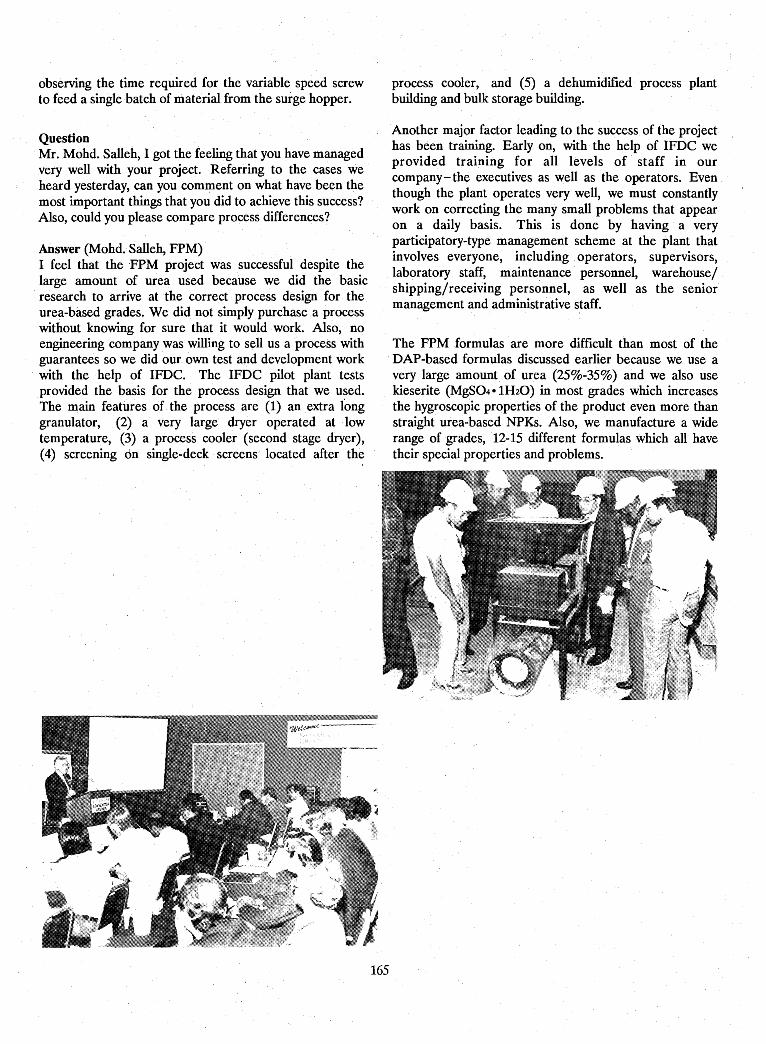
observing the time required for the variable speed screwto feed a single batch of material from the surge hopper.
QuestionMr. Mohd. Salleh, I got the feeling that you have managedvery well with your project. Referring to the cases weheard yesterday, can you comment on what have been themost important things that you did to achieve this success?Also, could you· please compare process differences?
Answer (Mohd. Salleh, FPM)I .feel that the 'FPM project was successful despite thelarge amount of urea used because we did the basicresearch to arrive at ,the correct process design for· theurea-based grades. We did not simply purchase a processwithout knowing for sure that it would· work. Also, noengineering company was willing to sell us a process withguarantees so we did our own test and development workwith the help of· IFDC. The IFDC pilot plant testsprovided the basis for the· process design· that we used.The main features of the process are(l) an extra longgranulator, (2) a· very ·large dryer operated at lowtemperature, (3) a process cooler (second stage dryer),(4) screening dn single-deck screens· located· after the
process cooler, and (5) a. dehumidified process plantbuilding and bulk storage building.
Another major factor leading to the success of the projecthas been training. Early on, with the help of IFDC weprovided training for all levels of· staff in ourcompany-the executives as well as the operators. Eventhough the plant operates .very well, we must constantlywork on correcting the many small problems that appearon a daily basis. This is done by having a veryparticipatory-type management scheme at. the plant thatinvolves everyone, including operators, supervisors,laboratory staff, maintenance personnel, warehouse/shipping/receiving personnel, as well as the seniormanagement and administrative staff.
The FPM formulas 'are more difficult than most of theDAP-based formulas discussed earlier because we use avery large amount of urea (25%-35%) and we also usekieserite(MgS04 e lH20) in most grades which increasesthe hygroscopic properties of the product even more thanstraight urea-based NPKs. Also, we manufacture a widerange of grades, 12-15 different formulas which all havetheir special properties and problems.
165
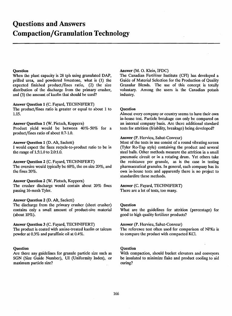
Questions and AnswersCompaction/Granulation Technology
QuestionWhen the plant capacity is 28 tph using granulated DAP,prilled urea, and powdered limestone, what is (1) theexpected finished product/fines ratio, (2) the sizedistribution of the discharge from the primary crusher,and (3) the amount of kaolin that should be used?
Answer Question 1 (C. Fayard, TECHNIFERT)The product/fmes ratio is greater or equal to about 1 to1.15.
Answer Question 1 (W. Pietsch, Koppern)Product yield would be between 40%-50% for aproduct/fmes ratio of about 0.7-1.0.
Answer Question 1 (D. Alt, Sackett)I would expect the fmes· recycle-to-product ratio to be inthe range of 1.5:1.0 to 2.0:1.0.
Answer Question 2 (C. Fayard, TECHNIFERT)The oversize would typically be 60%, the on size 20%, andthe fmes 20%.
Answer Question 2 (W. Pietsch, Koppern)The crusher discharge would contain about 20% fmespassing 16-mesh Tyler.
Answer Question 2 (D. Alt, Sackett)The discharge from the primary crusher (sheet crusher)contains only a small amount of product-size material(about 10%).
Answer Question 3 (C. Fayard, TECHNIFERT)The product is coated with amine-treated kaolin or talcumpowder at 0.3% and paraffmic oil at 0.4%.
QuestionAre there any guidelines for granule particle size such asSGN (Size Guide Number), UI (Uniformity Index), ormaximum particle size?
166
Answer (M. o. Klein, IFDC)The Canadian Fertilizer Institute (CFI) has developed aGuide of Material Selection for the Production of QualityGranular Blends. The use of this concept is totallyvoluntary. Among the users is the Canadian potashindustry.
QuestionAlmost every company or country seems to have their ownin-house test. Particle breakage can only be compared onan internal company basis. Are there additional standardtests for attrition (friability, breakage) being developed?
Answer (P. Hervieu, Sahut-Conreur)Most of the tests in use consist of a round vibrating screen(Tyler Ro-Tap style) containing the product and severalsteel balls. Other methods measure the attrition in a smallpneumatic circuit or in a rotating drum. Yet others takethe resistance per granule, as is the case in testingpharmaceutical granules. In general, each company has itsown in-house tests and apparently there is no project tostandardize these methods.
Answer (C. Fayard, TECHNIFERT)There are a lot of tests, too many.
QuestionWhat are the guidelines for attrition (percentage) forgood to high quality fertilizer products?
Answer (P. Hervieu, Sahut-Conreur)The reference test often used for comparison of NPKs isto compare the product with compacted KCl.
QuestionWith compaction, should bucket elevators and conveyorsbe insulated to minimize flake and product cooling to aidcuring?
Answer (W. Pietsch, Koppern)The product cures as it cools, therefore insulation is notrecommended.
Answer (D. Alt, Sackett)In most cases the material should be allowed to cool to aidcuring, thus insulation is not desired.
Answer (C. Fayard, TECHNIFERT)Insulating bucket elevators and/or the injection of hot airto remove the moisture from elevators and dust proofconveyers are recommended.
Answer (F. A. Dalton, FERQUIGUAOn the contrary, cooling aids the curing process. AtFerquigua, a belt conveyor is installed between thecompactors and the bucket elevators feeding the screensand mills. The purpose is to permit flake cooling to aidcuring.
Answer (M. O. Klein, IFDC)Curing of flake/product involves some degree of cooling.Condensation of moisture on the flake/product should beavoided. Such condensation can be controlled byventilating elevators, conveyors, and surge bins withdehumidified (dry) air.
QuestionWhat is the highest temperature of the flake leaving thecompactor?
Answer (W. Pietsch, Koppern)The temperature difference between the raw materialfeed and the flake is between 20° and 30°C.
Answer (P. Hervieu, Sahut-Conreur)In our experience, flake temperatures between 40°-50°Ccould be achieved under high compaction pressures.
Answer (C. Fayard, TECHNIFERT)A ternperature rise between 20° and 30°C above thetemperature of the raw material can be expected.
Answer (F. A. Dalton, FERQUIGUA)For products requiring a high compaction pressure, atemperature rise of about 30°_40°C is observed.
QuestionCould ammonium nitrate-based NPKs be produced bycompaction, and if so what is the highest allowablenitrogen content without the danger of explosion?
167
Answer (W. Pietsch, Koppern)It depends on other compounds (no organics). Maximumlevels are 20% N (about 60% ammonium nitrate) can becompacted; however, avoid this high level if possible.
Answer (C. Fayard, TECHNIFERT)Ammonium nitrate could be used at a level of up to 25%provided the following conditions are met:a. Organic matter is not used in the formula.b. Moisture content is low.c. pH of the formula is higher than 5.5.d. Special care must be taken when copper salts are
used.
Answer (F. A. Dalton, FERQUIGUA)The potential for explosion depends mainly on the organicmatter present in the formula.
QuestionWhat is the highest possible content of nitrogen in aurea-based NPK?
Answer (W. Pietsch, Koppern)The maximum urea content is between 30% and 40% withan average of 35%. Lower levels should be used in thetropics.
Answer (C. Fayard, TECHNIFERT)Maximum content is 30% N (about 65% urea).
Answer (F. A. Dalton, FERQUIGUA)At FERQUIGUA, the maximum content of urea we useranges from 25% to 30% depending on the humidity ofthe environment. Higher levels may be used, but productquality decreases.
QuestionWhat is the largest capacity compactor available on themarket?
Answer (W. Pietsch, Koppern)The capacity depends upon the formulation. Compactorsfor potassium chloride have up to 100 tph flakethroughputs.
Answer (C. Fayard, TECHNIFERT)Average throughput (flake capacity) of the largestcompactor is about 100 tph.
Answer (P. Hervieu, Sahut-Conreur)The largest capacity based on flake throughput is 100 tph(for potassium chloride). On the basis of product, thecapacity depends mainly on the desired size range of theproduct and the feed materials. In the case of potassiumchloride, this flake capacity (100 tph) can produce 40 tphproduct and about 30 tph (or more) product for other(NPK) fertilizers depending upon the NPK formulation.
Answer (M. O. Klein, IFDC)The largest compactor capacity for potassium chloride is100 tph of flake.
QuestionWhat is the caking tendency of compacted productscompared to those produced through wet granulation?
Answer (C. Fayard, TECHNIFERT)In general, the caking· tendencies of compacted productsare not very high. However, the critical relative humidityof the formula must be considered. The caking tendenciescan be lowered by the addition of multiple hydrates tostabilize the moisture. Coating will also play a significantrole in decreasing caking in tropical countries.
Answer (W. Pietsch, Koppern)The caking tendencies of compacted materials are usuallyquite low because of their dryness (low-moisture content).
Answer (F. A. Dalton, FERQUIGUA)The caking tendency of a compacted fertilizer depends onits hardness and composition. A soft compacted fertilizerwith a high urea content will cake more easily than a hardcompacted fertilizer with no urea (compacted borate, forexample). Thus, it is difficult to generalize.
Answer (J. J. Schultz, IFDC)As indicated by Mr. Dalton, it is risky to generalize aboutexpected caking tendencies of granular fertilizers. Toomany variables are involved to make a reliable prediction.The major disadvantage of compacted NPKs is theirirregular particle size and shape (rough texture). Thiscauses a greater granule-to-granule contact area, thusincreasing the probability of· caking compared withwell-formed, spherical granules, assuming all other factorsare equal. The only sure way to know is to performcomparative tests under controlled conditions.
QuestionWhy is a cage mill used to crush the raw material in thefeed to the compactor in the Guatemala plant?
168
Answer (W. Pietsch, Koppern)To provide a better size distribution of the feed materialto the compactor.
QuestionHow long do the compactor rollers last when abrasivematerials such as ground phosphate rock are used?
Answer (W. Pietsch, Koppern)No specific answer is possible since the amount of weardepends on the source of the phosphate rock. Estimatesindicate about 30,000 tonnes of product (about100,000 tonnes flake) as a minimum; the rollers can berebuilt (resurfaced) to offset wear.
Answer (C. Fayard, TECHNIFERT)From 5,000 hours to over 10,000 hours of operation can beexpected before the rolls must be resurfaced. One of thekey factors effecting wear is the quartz content of the feedmaterial.
QuestionOther than product presentation (appearance), what arethe other reasons for using small particle size materials inthe feed to the compactor?
Answer (C. Fayard, TECHNIFERT)The small particle size· is needed to obtain the exactformula in each granule. Also, it is generally desirable togrind the raw material so. that it has a maximum sizecorresponding to one-third the size of the smallest granulesize indicated in the specification of the product.
Answer (F. A. Dalton, FERQUIGUA)Process segregation is minimized with decreased rawmaterial particle size. Also, intermolecular forces ofattraction (which aid the compaction processes) increasewith decreasing particle size.
QuestionWhat is the smallest capacity compactor presentlyavailable for commercial use to manufacture fertilizers?
Answer (C. Fayard, TECHNIFERT)The smallest practical (economic) unit produces about5-10 tph product depending on the added value of thefmished product. In technical terms, it is possible to builda compactor that will produce as little as 0.5 tph.
Answer (W. Pietsch, Koppern)Units as small as 0.2-0.3 tph throughput (flake production)are commercially available.
QuestionDr. Pietsch indicated that commercially available smallplants have capacities as low as 0.2 tph flake. Mr. Hervieuindicated a range of 10-100 tph. Why this difference?
Answer (P. Hervieu, Sahut-Conreur)A commercial fertilizer granulation plant is rarely below5-10 tph product capacity. Technically speaking,compactors can be designed for capacities as low as0.1-0.2 tph (laboratory scale). It is important to note thatthe term "commercial scale" has many meanings. With ahigh value lawn and garden-type fertilizer, a profitablecommercial-scale operation may be in the 5-tph rangewhile 20-40 tph (product) may be required for a normal(lower value) agricultural fertilizer. '
QuestionOther than the need for avoiding further drying, what isthe moisture limit in the feed to compactor?
Answer (C. Fayard, TECHNIFERT)There is no simple answer. It depends on the thixotropicproperties of the raw material. For superphosphate-typeproducts the maximum is 5%-7% water.
Answer (W. Pietsch, Koppern)A maximum of 5% moisture is usually acceptabledepending on the mat~rial composition and productporosity. The product must be able to "hold" the moisture.The allowable level of moisture is heavily influenced bythe raw materials that are used.
QuestionCan a material such as ground pine tree bark or peat becompacted? Does the associated moisture content of thesematerials present problems with compaction?
Answer (W. Pietsch, Koppern)Yes, these materials can be compacted in small quantities(less or equal to 20% of the total formulation). Moisturedoes present problems; however, the larger problem is theelasticity of some of these materials.
Answer (C. Fayard, TECHNIFERT)Binders can be used with these materials to obtain tworesults: (a) increase the hardness and at the same timeincrease the yield, and (b) decrease the free moisture toimprove the storage properties.
QuestionCan powdered or pulverized limestone/dolomite becompacted?
Answer (P. Hervieu, Sahut-Conreur)We have industrial experience in compacting andbriquetting limestone/dolomite at relatively highpressures and without binders.
Answer (W. Pietsch, Koppern)Yes, it is possible to compact these materials.
QuestionCan potassium nitrate be compacted with other NPKmaterials?
Answer (C. Fayard, TECHNIFERT). We do not have any industrial-scale experience with the
compaction of potassium nitrate. However, it is necessaryto be cautious if the percentage of potassium nitratecontent of the formula is higher than 5%-10%. Also,please refer to my previous comment on ammoniumnitrate regarding safety precautions.
Answer (F. A. DaHon, FERQUIGUA)Potassium nitrate may be compacted with other materialsas well as by itself. .
Answer (W. Pietsch, Koppern)It is possible to compact potassium nitrate with othermaterials.
QuestionWhat is the effect of combining acidic materials such asammonium sulfate or residual phosphoric acid withcalcium- and magnesium-containing materials?
Answer (C. Fayard, TECHNIFERT)One of the main advantages of compaction is that itenables the incorporation of acidic and basic components
169
in the same formula. However, it is necessary to calculatea formula with a pH less than 6.5 when ammonium saltsare used.
QuestionWhat is the experience in manufacturing slow-releasefertilizers by use of compaction? To what extent, forexample, do granule density and certain components (rawmaterials) resist dissolution of the nutrients into the soilsolution?
Answer (C. Fayard, TECHNIFERT)The four methods we work with to control the nutrientrelease of compacted fertilizers are: (a) increasing the sizeof the granule, (b) decreasing the porosity of the granule,(c) coating the granule, and (d) use of a waterproofmgagent on the granules. The impact of each of these factorson the nutrient release characteristics depends upon anumber of factors including the raw materials, soilproperties, and climactic conditions.
QuestionIn the case of ammonium sulfate, organic impuritiesadversely affect the compaction process. Has the use ofbinders been tried to aid in the compaction of ammoniumsulfate?
Answer (W. Pietsch, Koppern)Yes. Binders have been tested with mixed results.
Answer (C. Fayard, TECHNIFERT)We have observed that the difficulties with compactingammonium sulfate are due mainly to the crystalcharacteristics of the raw material. These characteristicsare strongly influenced by the organic impurities presentduring ammonium sulfate crystallization.
QuestionWhat experience do you have in the manufacture ofhigh-analysis P20S + KCI granules which can then be bulkblended with other materials such as urea at about a 50:50ratio to obtain 24-10-10 or similar fertilizers?
Answer (C. Fayard, TECHNIFERT)We have experience. The key point is that the free watercontent of the compacted material must be very low toavoid caking especially when the compacted product isblended with urea.
170
Answer (F. A. Dalton, FERQUIGUA)At FERQUIGUA, several compacted products arespecifically produced for use in bulk blends. Thistechnique is mainly used in order to incorporate a rawmaterial which is not available in granular form, or whenthe premium for the granular form is very high, into bulkblends. Incorporating KCI in bulk blends in this way maynot be economical since the premium for granular KCIcompared with standard KCI is relatively low.
QuestionHow much water is used to polish/quench potash?
Answer (M. O. Klein, IFDC)Based on Saskatchewan's potash experience the norms are0.8%-1% water by weight with values as high as about .4.5%. Of course, one desires to take advantage of thesensible heat of the product for economic reasons andavoid an additional drying step.
QuestionFor compaction, is it necessary to have raw materials ofuniform size or in powder form? .
Answer (D. Alt, Sackett)It is not necessary to have the materials of a uniform sizefor compaction. For example, a mixutre of powderedmonoammonium phosphate (MAP), prilled urea, andstandard-grade potash compacts nicely. The required rawmaterial size distribution depends heavily upon theparticular formulation.
Answer (W. Pietsch, Koppern)It is best to have the raw materials in powder form and ofuniform size. This can be done by crushing the feed to thecompactor.
Answer (C. Fayard, TECHNIFERT)It is better to have the raw materials in powder form.
Answer (F. A. Dalton, FERQUIGUA)Materials both uniform in size and in powder form help inthe compaction proces.
QuestionHow important is the particle size- of raw materials in thefeed to compactor, especially in the case of materialswhich are difficult to compact like limestone? What is therecommended size distribution?
Answer CW. Pietsch, Koppern)The ideal particle size should be between 200 and 800 jjm(about 48- to 65-mesh, Tyler).
QuestionDo you have problems with scaling on the roller surfaces?How do you clean the roller surface?
Answer (C. Fayard, TECHNIFERT)Scaling problems usually occur when the compactionpressure is too high.
Answer (F. A. Dalton, FERQUIGUA)At FERQUIGUA, we usually clean the roller surfaces byprocessing hard, moderately abrasive raw materials suchas phosphate rock.
Answer CW. Pietsch, Koppern)Rolls can be cleaned either by washing or by running hardmaterial (for example, sand) through the unit for a shorttime.
QuestionCould you give an indication as to the cost of a 30-40 tph(product rate) compaction plant?
Answer (C. Fayard, TECHNIFERT)About US $10 million.
Answer (D. Alt, Sackett)Such a plant (installed cost basis) would cost betweenUS $7 and US $10 million.
Answer CW. Pietsch, Koppern)The cost would depend on location and the degree ofprocess sophistication.
QuestionWhat type of dust collection system is required for acompaction plant?
Answer CW. Pietsch, Koppern)A minimum system would require only cyclones; anoptimum system would use cyclones and wet scrubbers(bag fIlters should be avoided).
Answer (F. A. Dalton, FERQUIGUA)That would depend on local emission regulations. AtFERQUIGUA, all we use are dry cyclones since the plantis somewhat isolated and regulations are not strict. If we
171
needed to comply with stricter regulations we wouldprobably install a baghouse.
Answer (C. Fayard, TECHNIFERT)Bag futers are preferred for dust collection.
Answer (D. Alt, Sackett)The recommended dust collection system would consist ofcyclones and a baghouse-type collector. Wet scrubbers arenot recommended because disposal of scrubber liquorwould be a problem.
QuestionIs the use of dry cyclones adequate to collect the dustgenerated in the process? I~ the use of wet scrubbersrequired?
Answer (C. Fayard, TECHNIFERT)The use of bag filters is sufficient.
Answer CW. Pietsch, Koppern)The type of scrubbing system required will depend heavilyupon the local environmental regulations.
Answer (D. Alt, Sackett)Cyclones are usually not sufficient to completely clean theair, thus a baghouse may be installed after the cyclone. Awet scrubber is also a very good choice for fmal cleaningof the air after the cyclones if there is a way to use ordispose of the effluent liquor.
Comment (J. J. Schultz, IFDC)If bag-type collectors are used it may be better toeliminate the cyclones entirely to improve the operation ofthe bag collector. A wide particle-size distribution in thedust facilitates the formation of a "cake" on the collectorfabric that is more porous and more easily dislodged fromthe bag fabric. A disadvantage of such a system is that ifthe bag collector plugs it cannot be bypassed for cleaningas is the case if cyclones are installed ahead of the bagcollector to remove most of the dust. Of course, if bagcollectors are used, especially with urea-based products, agreat deal of precaution must be taken to keep the bagsdry to avoid plugging not only during operation but alsoduring periods when the plant is shut down. .
QuestionWhat is the maximum filler content m compaction/granulation? Can sand be used?
Answer (C. Fayard, TECHNIFERT)It is better not to use fillers because of the cost involved.Sand should not be used as it accelerates wear of theroller surface. Also, gypsum should not be used withurea-containing formulas due to unwanted reactionsbetween gypsum and urea.
Answer (F. A. Dalton, FERQUIGUA)The maximum filler content depends on the filler itself aswell as on the other components of the formula. The fillercontent may be as high as 60%. Sand should not be usedsince it wears the roller surface rapidly.
Answer (yV. Pietsch, Koppern)The filler content may be as high as 30%-40% of theformula. Sand causes high wear and therefore should notbe used. Gypsum and limestone are often used with goodresults.
QuestionIs dehumidification of the compaction plant buildingneeded?
Answer (C. Fayard, TECHNIFERT)Dehumidification is needed for NPKs having a high ureacontent (low critical relative humidity) if the plant islocated where the relative humidity exceeds about 50%.
Answer (F. A. Dalton, FERQUIGUA)It depends on the humidity of the environment at the plantsite. When it is high, dehumidification is recommendedsince it will reduce corrosion and will improve materialhandling.
Answer (W. Pietsch, Koppern)Dehumidification is advisable in humid climates.
Answer (D. Alt, Sackett)If your plant is in a high humidity location,dehumidification of the manufacturing plant area isrecommended.
QuestionIs it possible to use DAP instead of MAP m thecompaction of NPKs?
Answer (W. Pietsch, Koppern)Yes, this is possible and often done.
172
Answer (F. A. Dalton, FERQUIGUA)Yes, it is possible.
Answer (C. Fayard, TECHNIFERT)Yes, it is; economics should determine which material isused.
QuestionWhat are typical downtime causes in a compaction plantand how often do they occur?
Answer (C. Fayard, TECHNIFERT)Few downtimes occur. The availability of the plant isgreater than 90%.
Answer (F. A. Dalton, FERQUIGUA)Downtime is minimized if good maintenance is given to allthe equipment. Having two compaction lines, as we do,permits production and maintenance simultaneously.
Answer (W. Pietsch, Koppern)The downtimes consist mainly of scheduled maintenanceperiods for cleaning and preventative maintenance.
Answer (D. Alt, Sackett)Downtime is most typically caused by plugging of chutesand other equipment. An annual shutdown is required forgeneral mechanical maintenance.
Answer (J. J. Schultz, IFDC)Compaction plants employ many of the same operationsfound in a wet or chemical granulation plant (raw materialmeasuring and feeding, crushing, screening, andconveying). Therefore, the maintenance of these items isquite similar In· both processes. However, becausecompaction avoids the need for liquid phase and drying,these equipment systems (reactors, dryers, and coolers)are not needed. Also, the compacted material is more"flowable", thus, the chutes in a compaction plant are lesslikely to plug. In a typical wet or chemical granulationplant it is very important to stop operation on a regularschedule (about weekly for 8 h) to clean chutes andcrushers to avoid unscheduled shutdowns due to plugging.Finally, in humid regions, dehumidification of the processplant (compaction or wet/chemical granulation) will havea very significant positive impact on avoiding unscheduledshutdowns due to electrical failures, blinding of screens,and buildup on conveyor belts and idlers. Even in awell-managed wet or chemical granulation plant I think
that it would be difficult to obtain the same overall plantavailability factor that an equally well-managedcompaction plant could achieve.
QuestionMr. Fayard, you indicated that partially acidulatedphosphate rock (PAPR) was used in your compactedformulations. Is PAPR compatible with urea?
Answer (C. Fayard, TECHNIFERT)This depends on the quality of the partially acidulatedphosphate rock. Laboratory tests are required to evaluateeach case (formulation).
Answer (M. O. Klein, IFDC)Urea reacts with the water of hydration in monocalciumphosphate, a major component in TSP and SSP. Somehydrated monocalcium phosphate is also present inPAPR. Therefore, the actual effect must be tested todetermine if the particular PAPR is compatible with ureaand other components of the formulation. The ratio ofPAPR-to-urea is also an important factor.
QuestionWhen producing compacted KCI, what are the effects ofthe surfactant agents such as oils and amines that areusually present on the surface of the potash particles?
Answer (M. O. Klein, IFDC)Surfactants are used in the flotation process. Thesesurfactants adversely affect the compaction process.Therefore, they are burnt off (flashed) with hightemperature during the potash drying stage prior tocompaction.
Answer (W. Pietsch, Koppern)Oils and amines must be removed, usually by flashingthem off during drying as completely as possible. Antinesweaken the bonding strength between particles.
Answer (C. Fayard, TECHNIFERT)Coating materials and flotation agents also have a veryadverse effect on wet granulation of compound fertilizersas well as compaction. It is necessary to specify theselimits to the producer when the raw materials arepurchased.
QuestionWhen shipping compacted fertilizers in bulk, (a) wheredoes most of the degradation take place and (b) how does
173
actual degradation relate to laboratory-scale abrasiontests?
Answer (W. Pietsch, Koppern)Most of the degradation takes place during the loadingand unloading process. The exact relationship betweenactual results and laboratory tests is uncertain.
Answer (F. A. Dalton, FERQUIGUA)Degradation occurs mostly during loading and unloadingoperations.
Answer (C. Fayard, TECHNIFERT)Most of the degradation which results in the formation ofdust clouds takes place during loading, transportation, andunloading. The sharp edges of the granules should bedestroyed in a polishing drum to avoid such degradationand dusting.
Answer (M. O. Klein, IFDC)Most of the product breakdown occurs at transfer points.It should be of interest to the audience that studies havebeen made by potash producers to determine degradationfrom point-to-point during handling and transport andthat, in some cases, solutions have been implemented toreduce product degradation.
QuestionPlease comment on the relative shape and abrasionresistance of granules produced from flake crushed withchain mills, hammer mills, roll crushers, and other typesof crushers. Also, please comment on maintenance andprocessing problems of each crusher type.
Answer (W. Pietsch, Koppern)The crusher has no significant influence on the particleshape. Particle rounding is carried out in separate stepsincluding abrasion, wetting, drying, and coating.
Answer (F. A. Dalton, FERQUIGUA)The type of mill does not affect granule shape. Impactmills yield a harder product but increase the fmesproduction thus decreasing product output.
Answer (C. Fayard, TECHNIFERT)We have developed a new crusher/granulator system tomanufacture rounder products. We have also modified theflowsheet of our compaction unit. Although moremaintenance intensive, the new crusher/granulatorconcept increases the yield of product and offers improvedparticle roundness as well as improved productioneconomics.
QuestionIs there a compatibility problem when using urea, TSP,and phosphate rock in the feed to the compactor in themanufacture of NPKs?
Answer (C. Fayard,TECHNIFERT)Problems of compatibility exist. Therefore, each case mustbe treated separately (laboratory or pilot-plant scale)according to each formula (raw material type and mix).
Answer (F. A. Dalton, FERQUIGUA)Mixing urea with TSP should be avoided since they arenot compatible.
Answer (M. O. Klein, IFDC)As I have indicated earlier, urea will react with the waterof hydration attached to the monocalcium phosphate inthe TSP or PAPR. The impact of this and other factors onthe actual chemical compatibility of the mix is variable andtherefore should be tested in a laboratory beforebeginning commercial production.
Answer (J. J. Schultz, IFDC)Compatibility is a relative term. Even if certain materialmixtures are not totally compatible, they may besufficiently compatible if storage time is short. Marketconditions (requirements) should be factored in whendetermining "acceptable compatibility."
QuestionWhen kieserite is also added to a compaction formulacontaining urea, TSP, and phosphate rock, what problemsshould one expect?
Answer (C. Fayard, TECHNIFERT)Our experience has shown that kieserite has a positiveeffect on the compaction properties and quality of thefinished product.
Answer (F. A. Dalton, FERQUIGUA)Mixing kieserite with urea is not recommended since theyreact releasing water of hydration contained in thekieserite.
QuestionWhat are the disadvantages, if any, on the storageproperties when kieserite is present in the final product?Has MgO been used instead of kieserite, and what havebeen the consequences?
174
Answer (C. Fayard, TECHNIFERT)While kieserite improves the compaction properties of aformulation, its presence does adversely effect the storageproperties of the finished product.
Answer (J. J. Schultz, IFDC)Commercial-scale experience with mixtures of urea,phosphate rock, DAP, potash, and kieserite in wetgranulation clearly shows that kieserite tends to furtherlower the critical relative humidity of the mix. Forexample, a urea-based NPK without kieserite has a CRHof about 50% at 30°C while the CRH of thekieserite-containing formula is about 40%. Storage testsalso show that kieserite has an adverse effect. The mostimportant factor is free moisture; be sure to have themoisture very low (less than 0.7%) if kieserite is present.Magnesium oxide (MgO) is often used instead ofkieserite. It is important to note that in someformulations MgO will react quite rapidly with ammoniumsulfate and release ammonia. If the formula is not acidic,this free ammonia will be lost.
QuestionAt times water is added to the feed to the compactor.Could you please indicate where is the best location foradding the water?
Answer (W. Pietsch, Koppern)The best location is in the mixer (screw) prior to thecompactor where fresh feed and recycle are mixed.
Answer (C. Fayard, TECHNIFERT)We add water to the mixture of raw and recycled materialjust before the compactor.
Answer (F. A. Dalton, FERQUIGUA)The best place for water addition is where the recycle andprimary feed are mixed prior to compaction. AtFERQUIGUA this is achieved in a pug mill.
Answer (D. Alt, Sackett)If water is added to the process we recommend that it beadded in the pug mill used to premix the recycle with thefresh feed immediately prior to feeding to the compactor.
QuestionIn a typical "wet granulation" process liquid phase isrequired for granule formation. Is moisture required forthe compaction process or is the residual moisture, if any,sufficient in addition to the compaction pressure?
Answer (C. Fayard, TECHNIFERT)There are different binding mechanisms based on thecrystallization properties of the pro~u~t. For examp~e, freewater in the granule plays a sIgmficant role m thecompaction of products such as ground phosphate rock.Water also helps to facilitate salt bridges betweenparticles of the various raw materials.
Answer (W. Pietsch, Koppern) ..If water is present in small amounts, dIssolutIon andrecrystallization take~ place during drying. This formsinterparticle bridges. This often occurs naturally due. tothe conversion of mechanical energy to heat dunngcompaction.
QuestionPlease comment on the use of gravity feeders comparedwith force feeders in terms of advantages?
Answer (W. Pietsch, Koppern)Gravity feeders are used in large roller diametercompactors with materials having good flowability andcontaining a limited amount of fmes (minimum deaerationrequired). In this situation less equipment-relatedproblems are likely to occur along with less maintenanceand feed rate control problems. Gravity feeders are notrecommended when the feed material is very fine and theamount of entrapped air is high.
Answer (P. Hervieu, Sahut-Conreur)Gravity feeders can be used on raw materials with goodflowability and densities between 0.8 and 1 gjcm3
• Theyare used most often to compact potassium and sodiumchloride. However, the use of well-designed force feedersenables a better control of the feed rate to the compactorrolls.
QuestionWhat are the best screening methods to use whensearching for effective binders for compaction? Is there ascientific approach as opposed to the trial and errorapproach?
Answer (W. Pietsch, Koppern)The trial and error method is the only possibility left oncethe preselection process has been carried out based onavailability, price, and chemical acceptability(compatibility).
QuestionWe have found that traditional tests developed toascertain properties of granules are not always
reproducible. For example, the crushing strength dependson the shape of the granule and the abrasion test using adrum and steel balls is not always reliable. What methodsdo IEDC and other companies use?
Answer (C. Fayard, TECHNIFERT)A curing time of 2 days is sometimes necessary to improvethe quality of the product. A uniform curing time beforetesting often improves the reproducibility of test results.
Answer (W. Pietsch, Koppern)Our company uses Kali und Salz AG physical propertiestests as a reference.
Answer (M. O. Klein, IFDC)Physical properties tests used by IFDC are outlined in aspecial publication which is available for a small fee(IFDC Reference Manual IFDC R6). Most of these testsare standard tests which have been improved (adapted)over the years. As for potash, the abrasion test, althoughrelative, is satisfactorily reproducible as long as some testfactors are maintained. For example, the age of thesample is very important when testing fresh products.
QuestionIn a normal granulation process the product is cooledbefore transporting it to storage. Is this practice necessaryfor compacted urea-based NPK products? Could theseproducts be bagged directly from the process?
Answer (W. Pietsch, Koppern)There is no need for cooling. However, one should notbag freshly produced urea-based NPKs; they should beallowed to cure for several hours.
Answer (C. Fayard, TECHNIFERT)A curing time of 2 days before bagging is sometimesnecessary for urea-based NPKs.
Answer (J. J. Schultz, IFDC)The concept of "curing" before bagging is always a goodidea regardless of the process. A 1- or 2-day curingperiod, even if no cooling occurs, helps to allow thematerial to reach some level of equilibrium. Slight cakingdue to recrystallization is destroyed upon reclaiming thusdecreasing the likelihood of severe caking in the bag. Themore soluble the fertilizer mixture, the more important isthe need for a prebagging curing step. Of course, therelative humidity conditions of the curing area should bemaintained below the critical relative humidity of thefertilizer.
175
Delegates and Invited Speakers
AUSTRIA
Dr. Johannes HummelProcess Department (R&D)Voest Alpine IndustrieanlagenbauP.O. Box 9A-4031 LinzAUSTRIA
CANADA
Mr. William SmithPresidentInternational Fertilizer Systems Ltd.8240B - 31st Street S.E.Calgary, AlbertaCANADA T2C 1J1
CHILE
Mr. Mario Garri JohnsonProduction ManagerCompania Sud Americana
de Fosfatos SA.P.O. Box 45PencoCHILE
COLOMBIA
Mr. Luis R. Gulfo CaballeroHead - Fertilizer Technical GroupMonomeros Colombo Venezolanos, SA.P.O. Box 3205BarranquillaCOLOMBIA
COSTA RICA
Eng. Luis A. Rojas MontealegreProduction EngineerFertilizantes de Centro America SA.Apdo.316Puntarenas 5400COSTA RICA
(S) Denotes invited speaker or panel member.
176
COSTA RICA
Eng. Miguel Saurez FernandezTechnical Services SuperintendentFertilizantes de Centro America SA.Apdo.316PuntarenasCOSTA RICA
EGYPT
Mr. Taber Mahmood Salama MehanaElectricity Head SectorEl Nasr Company for Fertilizers and
Chemical Industries (SEMADCO)TalkhaEGYPT
Mr. Adel Mahrous MahmoudManager, Mechanical WorkshopsThe Financial Industrial CompanyKafr El ZayatEGYPT
Mr. Youssef Mohamed Youssef IsmailChief, Sulphuric Acid- PlantAbu Zaabal Fertilizer and ChemicalCompany
17, Kasr El Nil StreetAbu ZaabalEGYPT
Mr. Magdy Moharram Abou GabalManager, Fertilizer Production
AdministrationThe Financial Industrial CompanyAssuit, MankabadEGYPT
FINLAND
Mr. Taisto KoivumakiDevelopment ManagerKemira OyEspoo Research CenterP.O. Box 44SF-02271 EspooFINLAND
FRANCE
Mr. C. Fayard (S)PresidentTechnifert SA.BP6135406 Saint Malo CedexFRANCE
Mr. Pascal Hervieu (S)Sales ManagerSahut-Conreur and Company700, Rue CorbeauB.P.4959590 RaismesFRANCE
GUATEMALA
Mr. FrankA. Dalton (S)Operations ManagerDISAGRO/FERQUIGUAAnillo Periferico 17-36, Zona 1101011, Guatemala CityGUATEMALA
INDIA
Mr. S. K. Chatterjee (S)Vice President-TechnicalZuari Agro Chemicals Ltd.Jaikisaan Bhawan, ZuarinagarGoa-403.726INDIA
Mr. K. K. KaulManager- Fertilizer Technical ServicesShriram Fertilisers and ChemicalsShriramnagarKota - 324 004INDIA
Mr. S. Ramadurai (S)Manager - TechnicalCoromandel Fertilisers Ltd.1-2-10 Sardar Patel RoadSecunderabad 500 003INDIA
(S) Denotes invited speaker or panel member.
177
INDIA
Mr. T. A. Sankaran (S)Plant ManagerFACfCochin DivisionAmbalamedu 682 303CochinINDIA
INDONESIA
Mr. Eric F. DjohanCorporate AdvisorP.T. Rolimex CorporationJ1. Ir. H. Juanda 3/31 P-QJakartaINDONESIA
Mr. Rachmanto HandaniProduction Planning StaffP.T. Pupuk SriwidjajaP.O. Box 084PalembangINDONESIA
Mr. Yohanes HascaryoSuperintendent--Ammonia PlantPetrokimia GresikJ1. Jend. A. YaniP.O. Box 2Gresik, East JavaINDONESIA
Mr. YusufKodradiProcess Engineer SuperintendentPT. Petrokimia GresikJ1. Jend. A. YaniP.O. Box 2Gresik, East JavaINDONESIA
Mr. Patria Sugeng K.Process DesignP.T. Pupuk SriwidjajaP.O. Box 084PalembangINDONESIA
ITALY
Dr. Angelo CorchiaInorganics Process DepartmentSnamprogetti30 Palazzo Uffici 1 No 2B'2I1J97 San DonatoMilanoITALY
JORDAN
Mr. Jamal AmiraAssistant Technical ManagerThe Arab Potash Company Ltd.P.O. Box 1470AmmanJORDAN
MALAYSIA
Mr. Koh Ting TiewWorks ManagerChemical Company of Malaysia BerhadShah Alam WorksP.O. Box 9541908 KlangSelangor Darul EhsanMALAYSIA
Mohd Salleh Bin Darus (S)General ManagerFPMSdnBhdLot 115, Johor Port Authority AreaP.O. Box 2981707 Pasir Gudang, JohorMALAYSIA
Mr. Yeo Chin KiangProduction EngineerFPMSdnBhdLot 115, Johor Port Authority AreaP.O. Box 2981707 Pasir Gudang, JohorMALAYSIA
MEXICO
Mr. Enrique M. GalvanManagerGro-Green Campbell de Mexico, Inc.Melchor Ocampo 193-1206Mexico, D.F.1l3OOMEXICO
(S) Denotes invited speaker or panel member.
178
MEXICO
Mr. ManuelP. MarencoProduction ManagerGro-Green Campbell de Mexico, Inc.Melchor Ocampo 193Mexico, D.F. 11300MEXICO
NIGERIA
Mr. N. B. AjalaTechnical Services ManagerNAFCONPMB5180Port HarcourtRivers StateNIGERIA
Mr. T. Ramaswami (S)NPK Plant SuperintendentNAFCONPMB 5180Port HarcourtRivers StateNIGERIA
TURKEY
Mr. Hasan AsIanGeneral ManagerTurkish Fertilizer CompanyElazig Isletmesi Muessesesi Mudurlugu23900 Sivrice/ElazigTURKEY
Mr. Ekrem YilmazAssistant General DirectorSamsun Gubre Sanayii A.S.Genel MudurluguSamsunTURKEY
UNITED STATES
Mr. Daniel M. Alt (S)Vice President, EngineeringThe A. J. Sackett and Sons Company1701 South Highland AvenueBaltimore, Maryland 21224
Mr. Fred CarneyManager, Process DevelopmentPursell Industries201 West Fourth StreetP.O. Box 540Sylacauga, Alabama 35150
UNITED STATES
Mr. B. W. Curtis (S)Research ChemistTennessee Valley AuthorityMuscle Shoals, Alabama 35660
Mr. John Detrick (S)Manager, Technology-Market
DevelopmentPursell Industries201 West Fourth StreetP.O. Box 540Sylacauga, Alabama 35150
Mr. Mahesh GandhiProcess EngineerM. W. Kellogg CompanyThree Greenway PlazaHouston, Texas 77478
Dr. Larry L. HammondManager, Rock Phosphate Marketing
and Agronomic ProgramsTexasgulf Chemicals CompanyP.O. Box 30321Raleigh, North Carolina 27622-0321
Mr. L. D. Hoffman (S)Manager, SalesFEECO International3913 Algoma RoadGreen Bay, Wisconsin 54311
Dr. Richard MayerSupervisor, R&DAllied-Signal CorporationP.O. Box 31Petersburg, Virginia 23804
Mr. M. M. Norton (S)Senior ScientistTennessee Valley AuthorityMuscle Shoals, Alabama 35660
(S) Denotes invited speaker or panel member.
179
UNITED STATES
Mr. B. R. Parker (S)Chemical EngineerTennessee Valley AuthorityMuscle Shoals, Alabama 35660
Mr. Robert (Bob) ParkerPlant Superintendent (SCD)Pursell Industries201 West Fourth StreetP.O. Box 540Sylacauga, Alabama 35150
Mr. GaryL. PepperSenior Project EngineerDavy McKee CorporationSuite 7002925 BriarparkHouston, Texas 77042
Dr. Wolfgang Pietsch (S)PresidentKoppern Equipment, Inc.5215 Chinley CourtCharlotte, North Carolina 28226
Mr. James G. SawyerManager, TechnicalAllied-Signal CorporationP.O. Box 31Petersburg, Virginia 23804
Mr. G. H. Wesenberg (S)Vice President, Process EngineeringFEECO International3913 Algoma RoadGreen Bay, Wisconsin 54311
Appendix
Production of Granular NPKs inAmmonium Phosphate Plants
Some Important Differences
International Fertilizer Development CenterTechnical Bulletin T-36December 1989
Productionof
GranularNPKs
in AmmoniumPhosphate Plants
Some Important Differences
by James J. Schultz
International Fertilizer Development Center
PrefaceThe plant design and operating parameters required for producing agglomerated compound (NPK) fertilizers, especially urea-based and other temperaturesensitive and hygroscopic granular products, are often quite different from thoserequired for the production of conventional ammoniurn phosphate fertilizers,i.e., diammonium phosphate (DAP) or monoammonium phosphate (MAP). Thesedifferences should be carefully considered when adapting a DAP/MAP plantfor the production of NPKs. The plant design and operating criteria describedin this bulletin are intended to serve as a "check Iist" that may be used to helpguide those involved in the planning and design of new NPK projects or themodification of existing units.
The data and recommendations contained in this bulletin are the distillationof a broad international base of experiences and results collected and formulated over a number of years. The author is grateful for the valuable insight offeredby the many production, engineering, and research/development organizationsand individuals who candidly shared their experiences and knowledge, offeredsuggestions, and otherwise stimulated and supported the preparation of thispublication.
Library of Congress Cataloging-in-Publication Data
Schultz, James J., 1936-Production of granular NPKs in ammonium phosphate
plants-some important differences.
(Technical bulletin I International FertilizerDevelopment Center ; T-36)
Includes bibliographical references.1. Nitrogen fertilizers. I. Title.
II. Series: Technical bulletin (International FertilizerDevelopment Center) ; T-36.TP9634. N5S38 1989 668'.624 89-26790ISBN 0-88090-084-9
International Fertilizer Development CenterP.O. Box 2040Muscle Shoals, Alabama 35662
Phone No. 205-381-6600TWX-810-731-3970 IFDEC MCHLTelefax: (205)381-7408
Edited by E. N. RothTypesetting and Layout by P. F. SandlinCover Design by F. RUdolphGraphics by T. L. McGee
IFDC publications are listed in Publications of the International FertilizerDevelopment Center, General Publication IFDC-G-1, which is available freeof charge.
Table of Contents
Introduction 1Importance of Granule Formation Mechanism 1
Agglomeration-Type Processes 1Accretion-Type Processes..................................................................................... 1
Equipment and Operating Parameters Unique to Agglomerated NPKs 2Raw Material Particle Size 3Liquid Phase 3Estimating Liquid Phase Values 4Heat of Chernical Reaction 4Insoluble Binders 5Liquid Phase Control 5Acid/Ammonia Neutralization Methods 5Preparing the Production Formulation 7Dry Raw Material Feed System 8Solids Recycle 10Granulator 10Cocurrent Dryer 10Countercurrent Process Cooler (Second-Stage Dryer) 12Screens 14Oversize Crushers 15Product Cooler 15Conditioning 16Storage and Bagging 16Process Plant Dehumidification 16
Recommendations Specific to the Production of NPKs Containing Urea 16Veri'fication of Recomrnended Plant Design and Operating Parameters 17Conclusion 17Appendix-Design and Operating Criteria for Urea-Based NPK
Granulation Plants 18Bibliography 20
/
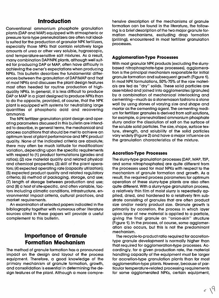
IntroductionConventional ammonium phosphate granulationplants (DAP and MAP) equipped with atmospheric orpressure tank-type preneutralizers are often not ideally suited for the production of granular NPK fertilizers,especially those NPKs that contain relatively largeamounts of urea or other very soluble, hygroscopic,and temperature-sensitive salt mixtures. As a result,many combination DAP/NPK plants, although well suited for producing DAP or MAP, often have difficulty inactlieving ttle owner's expectations when producingNPKs. This bulletin describes the fundamental differences between the granulation of DAP/MAP and thatof most NPKs and discusses the plant design featuresmost often needed for routine production of highquality NPKs. In general, it is less dif'ficull to produceDAP or MAP in a plant designed to produce NPKs thanto do the opposite, provided, of course, that the NPKplant is equipped with systems for neutralizing largequantities of phosphoric acid and recoveringammonia.
The NPK fertilizer granulation plant design and operating parameters discussed in this bulletin are intended to describe, in general terms, the mechanical andprocess conditions that should be met to achieve anoptimum level of plant performance and NPK productquality. None of the indicated criteria are absolute;there may often be much latitude for modification/variation, depending upon the speci'fic requirementswith respect to (1) product formulations (grades andratios); (2) raw material quality and related physicaland chemical properties; (3) skill of the plant operators; (4) expected operating rate (capacity utilization);(5) expected product quality and related regulatorycriteria; (6) method of packaging, storage, and use;(7) length of storage between production and use;and (8) a host of site-specific, and often variable, factors inclUding climatic conditions, infrastructure, environmental impact criteria, cultural practices, andmarket requirements.
An examination of selected papers indicated in thebibliography together with numerous other literaturesources cited in these papers will provide a usefulcomplement to this bulletin.
Importance of GranuleFormation Mechanism
The method of granule formation has a pronouncedimpact on the design and layout of the processequipment. Therefore, a good knowledge of theprimary mechanism of granule formation, growth,and consolidation is essential in determining the design features of the plant. Although a more compre-
hensive description of the mechanisms of granuleformation can be found in the literature, the following is a brief description of the two major granule formation mechanisms, excluding drop formation(prilling), encountered in most fertilizer granulationprocesses.
Agglomeration-Type ProcessesWith most granular NPK products (excluding the slurrybased nitrophosphate-type processes), agglomeration is the principal mechanism responsible for initialgranule formation and subsequent growth (Figure 1).In most NPK formulations, 50%-75% of the raw materials are fed as "dry" solids. These solid particles areassembled and joined into agglomerates (granules)by a combination of mechanical interlocking andcementing-much as a stonemason fashions a stonewall by using stones of varying size and shape andmortar as'the cementing agent. The cementing medium for fertilizer granules is derived from salt solutions,for example, a preneutralized ammonium phosphateslurry and/or the dissolution of saU on the surface ofthe soluble solid particles. The size. shape, surface texture, strength, and solubility of the solid particlesvary widely (Figure 2) and have a major influence onthe granulation characteristics of the mixture.
Accretion-Type ProcessesThe slurry-type granulation processes (DAP, MAP, TSP,and some nitrophosphates) are quite different fromthe processes used for most NPKs with respect to themechanism of granule formation and growth. As aresult, the required process parameters for optimumoperation of these slurry-type plants are also oftenquite di'fferent. With a slurry-type granulation process,a relatively thin film of moist slurry is repeatedly applied, dried, and hardened to a relatively firm substrate consisting of granules that are often productsize and/or nearly product size. Granule growth isprimarily by accretion, the process in which layerupon layer of new material is applied to a particle,giving the final granule an "onion-skin" structure(Figure 1). In the process, of course, some agglomeration also occurs, but this is not the predominantmechanism.
The recycle-to-product ratio required for accretiontype granule development is normally higher thanthat required for agglomeration-type processes. Accordingly, for a given production rate, the materialhandling capacity of the equipment must be largerfor accretion-type granulation plants than for mostagglomeration-type plants..However, because of particular temperature-related processing requirementsfor some agglomerated NPKs, certain equipment,
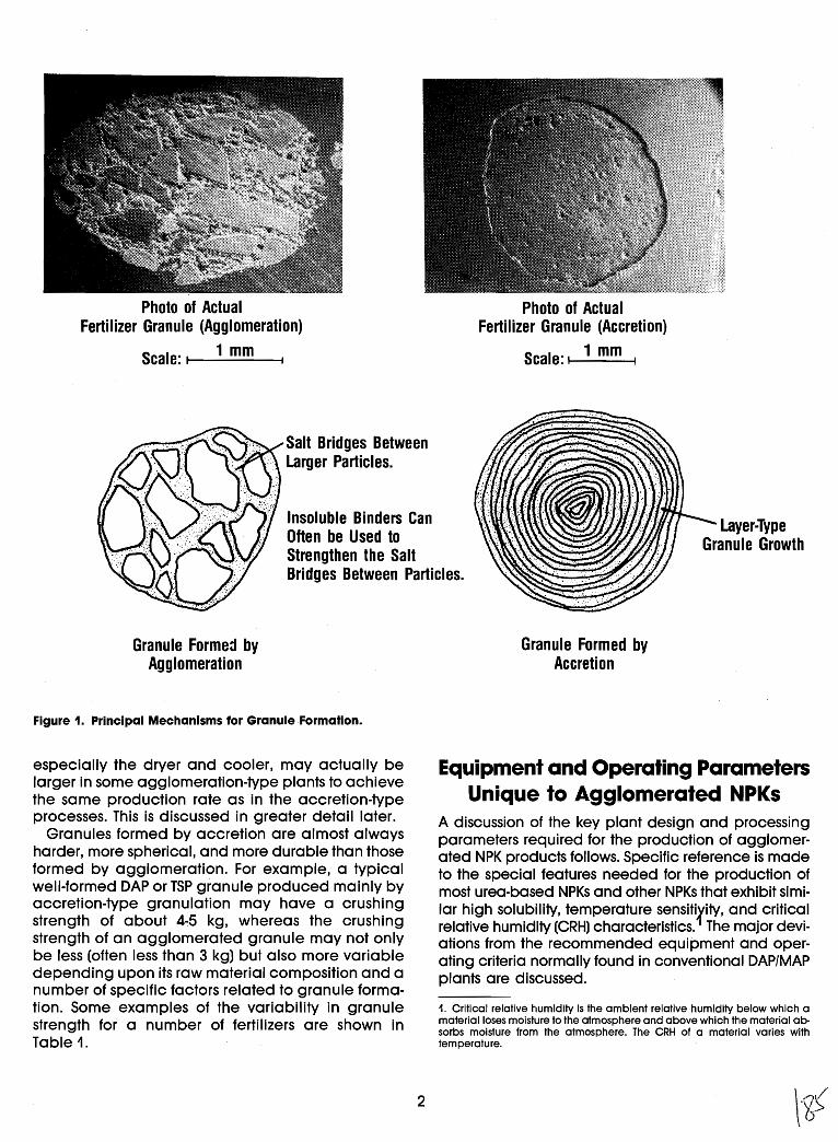
Photo of ActualFertilizer Granule (Agglomeration)
Scale: t-I_1_m_m_-1
Photo of ActualFertilizer Granule (Accretion)
Scale: I 1 mm I
Insoluble Binders CanOften be Used toStrengthen the SaltBridges Between Particles.
Granule Forme:! byAgglomeration
Figure 1. Principal Mechanisms for Granule Formation.
Granule Formed byAccretion
Layer-TypeGranule Growth
especially the dryer and cooler, may actually belarger in some agglomeration-type plants to achievethe same production rate as in the accretion-typeprocesses. This is discussed in greater detail later.
Granules formed by accretion are almost alwaysharder, more spherical, and more durable than thoseformed by agglomeration. For example, a typicalwell-formed DAP or TSP granule produced mainly byaccretion-type granulation may have a crushingstrength of about 4~5 kg, whereas the crushingstrength of an agglomerated granule may not onlybe less (often less than 3 kg) but also more variabledepending upon its raw material compositi.on and anumber of specific factors related to granule formation. Some examples of the variability in granulestrength for a number of fertilizers are shown inTable 1.
2
Equipment and Operating ParametersUnique to Agglomerated NPKs
A discussion of the key plant design and processingparameters required for the production of agglomerated NPK products follows. Specific reference is madeto the special features needed for the production ofmost urea-based NPKs and other NPKs that exhibit similar high solubility, temperature sensiti.rity, and, critic~1relative humidity (CRH) characteristics. The major devIations from the recommended equipment and operating criteria normally found in conventional DAP/MAPplants are discussed.
1. Critical relative humidity is the ambient relative humidity below which amaterial loses moisture to the atmosphere and above which the material absorbs moisture from the atmosphere. The CRH of a material varies withtemperature.
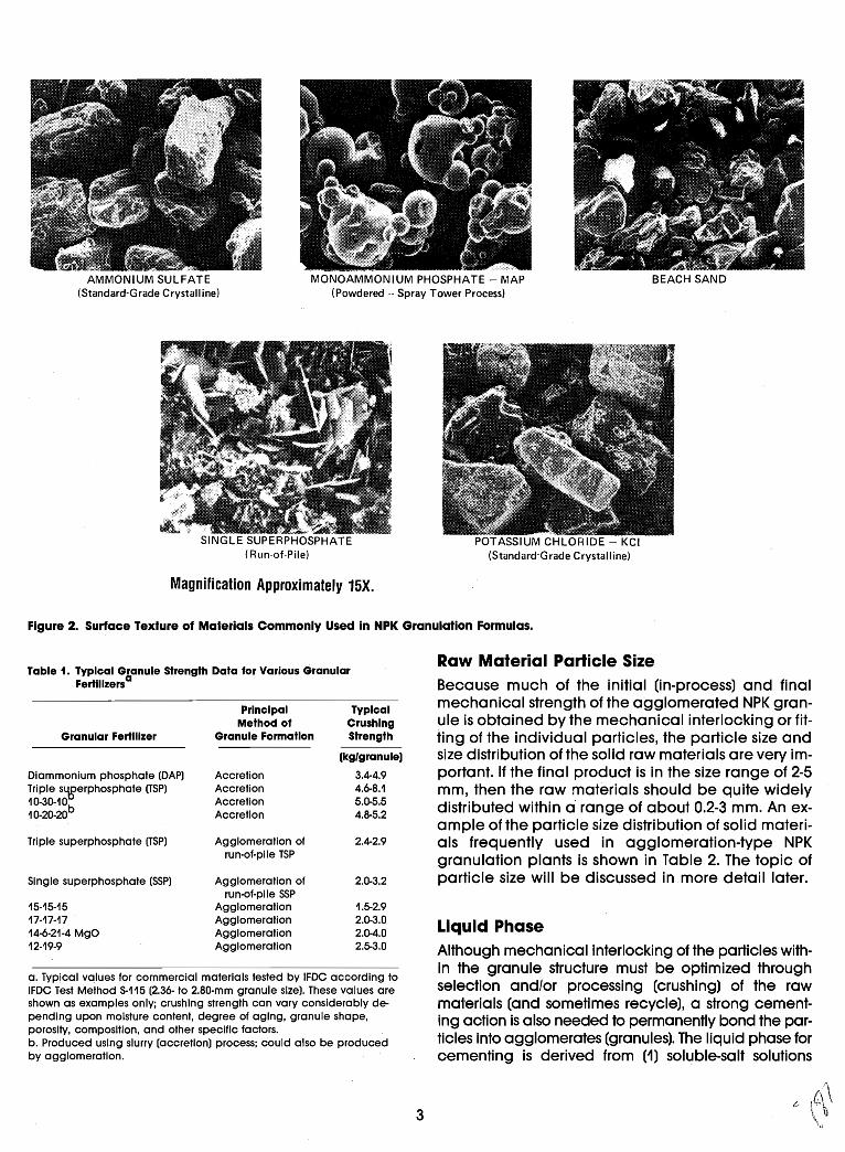
AMMONIUM SULFATE(Standard-Grade Crystalline)
- -MONOAMMON IUM PHOSPHATE - MAP
(Powdered -. Spray Tower Process)
SINGLE SUPERPHOSPHATE(Run-at-Pile)
Magni'fication Approximately 15X.
POTASSIUMCHLORIDE - KCI(Standard-Grade Crystalline)
Figure 2. SUrface Texture of Mal'erials Commonly Used in NPK Granulation Formulas.
Table 1. Typical Granule Strength Data for Various GranularFertlllzersa
Principal TypicalMethod of Crushing
Granular Fertilizer Granule Formation Strength
(kg/granule)
Oiammonium phosphote (OAP) Accretion 3.4-4.9Triple s~erphosphate (TSP) Accretion 4.6-8.110-30-10
bAccretion 5.0-5.5
10-20-20 Accretion 4.8-5.2
Triple superphosphate (TSP) Agglomeration of 2.4-2.9run-of-pile TSP
Single superphosphate (SSP) Agglomeration of 2.0-3.2run-of-pile SSP
15-15-15 Agglomeration 1.5-2.917-17-17 Agglomeration 2.0-3.014-6-21-4 MgO Agglomeration 2.0-4;012-19-9 Agglomeration 2.5-3.0
a. Typical values for commercial materials tested by IFOC according toIFOC Test Method S-115 (2.36- to 2.80-mm granule size). These values areshown as examples only; crushing strength can vary considerably depending upon moisture content, degree of aging, granule shape,porosity, composition, and other specific factors.b. Produced using slurry (accretion) process; could also be producedby agglomeration.
3
Raw Material Particle SizeBecause much of the initial (in-process) and finalmechanical strength of the agglomerated NPK granule is obtained by the mechanical interlocking or fitfingof the individual particles, the particle size andsize distribution of the solid raw materials are very important. If the final product is in the size range of 2-5mm, then the raw materials should be quite widelydistributed within a" range of about 0.2-3 mm. An example of the particle size distribution of solid materials frequently used in agglomeration-type NPKgranulation plants is shown in Table 2. The topic ofparticle size will be discussed in.more detail later.
Liquid PhaseAlthough mechanical interlocking of the particles within the granule structure must be optimized throughselection and/or processing (crushing) of the rawmaterials (and sometimes recycle), a strong cementing action is also needed to permanently bond the particles into agglomerates (granules). The liqUid phase forcementing is derived from (1) sol~ble-salt solutions
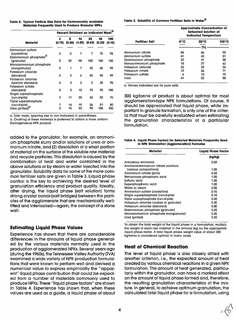
Table 2. Typical Particle Size Data for Commercially Available Table 3. Solubility of Common Fertilizer Salts In Watera
Materials Frequently Used to Produce Granular NPKsApprOXimate Concentration of
Percent Retained on Indicated Mesha Saturated Solution atIndicated Temperature
4 8 16 28 48 ·100Material (4.75) (2.36) (1.00) (0.60) (0.30) (0.15) Fertilizer Salt O°C 20°C 100°C
(%) ---------Ammonium sulfate(crystalline) 0 0 7 75 98 Ammonium nitrate 54 66 90
Diammonlum phosPhateb Ammonium sulfate 41 43 51
(granular) 0 22 98 100 100 100 Dlammonlum phosphate 30 41 58
Monoammonium phosphate Monoammonlum phosphate 18 27 63
(nongranular) 0 7 30 65 90 Potassium chloride 22 25 36
Potassium chloride Potassium nitrate 12 24 71
(standard) 0 0 6 55 90 99 Potassium sulfate 6 10 19
Potassium chloride Urea 41 52 88
(special standard) 0 a 0 5 35 90Potassium sulfate a. Values Indicated are for pure salts.
(standard) 0 0 15 75 95 100Single superphosphate
300 kg/tonne of product is about optimal for most(run-of-pile) 3 11 25 36 52 76Triple superphosphate agglomeration-type N~K formulations. Of course, it(run-of-plle) b 7 14 19 26 51 80 should be appreciated that liqUid phase, while im-
Urea (prilled) a 15 92 95 100 100portant in granUle formation, is only one of the criter-
a. Tyler mesh, opening size in mm indicated in parentheses. ia that must be carefully evaluated when estimatingb. Crushing of these materials Is preferred to obtain a more uniform the granulation characteristics of a particular(homogeneous) NPK prodUCt.
formulation.
Table 4. Liquid Phase Factors for Selected Materials Frequently UsedIn NPK Granulation (Agglomeration) Formulas
added to the granulator, for example, an ammonium phosphate slurry and/or solutions of urea or ammonium nitrate, and (2) dissolution of a small portionof material on the surface of the soluble raw materialand recycle particles. This dissolution is caused by thecombination of heat and water contained in theabove solutions or by steam or water injected into thegranulator. Solubility data for some of the more common fertilizer salts are given in Table 3. liqUid phasecontrol is the key to achieving the desired level ofgranulation efficiency and product quality. Ideally,after drying, the liquid phase (salt solution) formsstrong crystal bonds (salt bridges) between the particles of the agglomerate that are mechanically wellfitted and interlocked-again, the concept of a stonewall.
Material
Anhydrous ammoniaAmmonia/ammonium nitrate solutions
(various compositions)Ammonium nitrate (prills)Wet-process phosphoric acidSulfuric acidSuperphosphoric acidWater or steamAmmonium sulfate (crystalline)Single superphosphate (run-of-pile)Triple superphosphate (run-of-plle)Potassium chloride (coarse or granUlar)Potassium chloride (standard)Diammonium phosphate (granUlar)Monoammonium phosphate (nongranular)Urea (prilled)
Liquid Phase Factor
(kg/kg)
0.50
1.000.301.001.001.002.000.100.100.200.300.000.250.200.30
Estimating Liquid Phase ValuesExperience has shown that there are considerabledifferences in the amounts of liquid phase generated by the various materials normally used in theproduction of agglomerated NPKs. Several years ago(during the 1960s), the Tennessee Valley Authority (TVA)examined a wide variety of NPK production formulations that were known to perform well and devised anumerical value to express empirically the "apparent" liqUid phase contribution that could be expected from a number of materials commonly used toproduce NPKs. These "liquid phase factors" are shownin Table 4. Experience has shown that, when thesevalues are used as a guide, a liquid phase of about
4
To obtain the total weight of the liqUid phase in a formulation, multiplythe weight of each raw material In the formula (kg) by the appropriateliquid phase factor. A total liquid phase weight value of about 300kg/tonne is considered optimal in many cases
Heat of Chemical ReactionThe level of liqUid phase is also closely allied withanother criterion, Le., the expected amount of heatcreated by various chemical reactions in a given NPKformulation. The amount of heat generated, particularly within the granulator, can have a marked effecton the amount of liqUid phase formed and, therefore,the resulting granulation characteristics of the mixture. In general, to achieve optimum granulation, thecalculated total liquid phase for a formulation, using
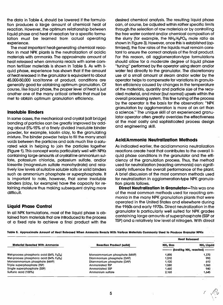
the data in Table 4, should be lowered if the formulation produces a large amount of chemical heat ofreaction. However, the optimum relationship betweenliquid phase and heat of reaction for a specific formulation must be learned from actual operatingexperience.
The most important heat-generating chemical reaction in most NPK plants is the neutralization of acidicmaterials with ammonia. The approximate amount ofheat released when ammonia reacts with some common fertilizer materials is shown in Table 5. As with liquid phase, experience has shown that if the amountof heat released in the granulator is equivalent to about45,000-50,000 kcal/tonne of product, conditions aregenerally good for obtaining optimum granulation. Ofcourse, like liquid phase, the proper level of heat is justanother one of the many critical criteria that must bemet to obtain optimum granulation efficiency.
Insoluble BindersIn some caseSj the mechanical and crystal (salt bridge)bonding of particles can be greatly improved byadding about 5%-15% of a finely divided insoluble binderpowder, for example, kaolin claY,to the granulatingmixture. The. binder powder helps to fill the many smallvoids between the particles and acts much like a saturated wick in helping to join the particles together(Figure 1). This concept works particularly well with NPKscontaining large amounts of crystalline ammonium sulfate, potassium chloride, potassium sulfate, and/orkieserite (magnesium sulfate monohydrate) and relatively low levels of suitable soluble salts or solid binderssuch as ammonium phosphate or superphosphate. Itis important to note, however, that some insolublebinders (clay, for example) have the capacity for retaining moisture thus making subsequent drying moredmicult.
liquid Phase ControlIn all NPK formulations, most of the liquid phase is obtained from materials that are introduced 1'0 the processat a fixed rate to achieve a final product with the
desired chemical analysis. The resulting liquid phasecan, of course, be adjusted within rather specific limitsthrough the selection of raw materials or by controllingthe free water content and/or chemical composition ofthe slurry (for example, the NH3 :H3P04 mole ratio asshown in Figure 3). However, once this is established (optimized), the flow rates of the liquids must remain constant to ensure the correct analysis of the final product.For this reason, all agglomeration-type formulationsshould allow for a moderate degree of liquid phase"tuning" performed by the operator using steam and/orwater fed directly to the granulator. The discretionaryuse of a small amount of steam and/or water by theoperator helps to compensate for variations in granulation efficiency caused by changes in the temperatureof the materials, quantity and particle size of the recy,.cled material, and minor (but normal) upsets within theoverall processing system. This fine tuning of the processby the operator is the basis for the observation: "NPKgranulation by agglomeration is more of an art thana science." The unique skill of an experienced granulator operator often greatly overrides the effectivenessof the most costly and sophisticated process designand engineering skill.
Acid/Ammonia Neu1'ralization MethodsAs indicated earlier, the acid/ammonia neutralizationreactions create heat that contributes to the overall Iiquid phase condi'tions in the granulator and the efficiency of the granulation process. Thus, the methodused for neutralization (reacting ammonia) can significantly influence the overall performance of the plant.A brief discussion of the most common methods usedfor neutralization in agglomeration-type NPK granulation plants follows.
Direct Neutralization in Granulator-This was oneof the most common methods used for reacting ammonia in the many NPK granulation plants that wereoperated in the United States and elsewhere duringthe 1960s and early 1970s. Direct neutralization in thegranulator is particularly well suited for NPK gradescontaining large amounts of superphosphate (SSP orTSP) and a relatively low level of nitrogen. With direct
Table 5. Approximate Amount of Heat Released When Ammonia Reacts With Various Materials Commonly Used to Produce Granular NPKs
Heat Released
Material Reacted With Ammonia
Wet-process phosphoric acid (54% PzOs)Wet-process phosphoric acid (54% PzOs)Monoammonlum phosphate (MAP)Triple superphosphate (TSP)Single superphosphate (SSP)Sulfuric acid (100%)
Reaction Product (solid)
Monoammonium phosphate (MAP)Dlammonium phosphate (DAP)Dlammonlum phosphate (DAP)Ammoniated TSPAmmoniated SSPAmmonium sulfate
NH3 Gas NH3 LIquid
------- (kcal/kg NH3 reacted) ------
1.890 1,3701,510 9901.130 6101,580 1.0601,460 9402,165 1.645
5 ( 11\)\ ,.; tJ\ .....
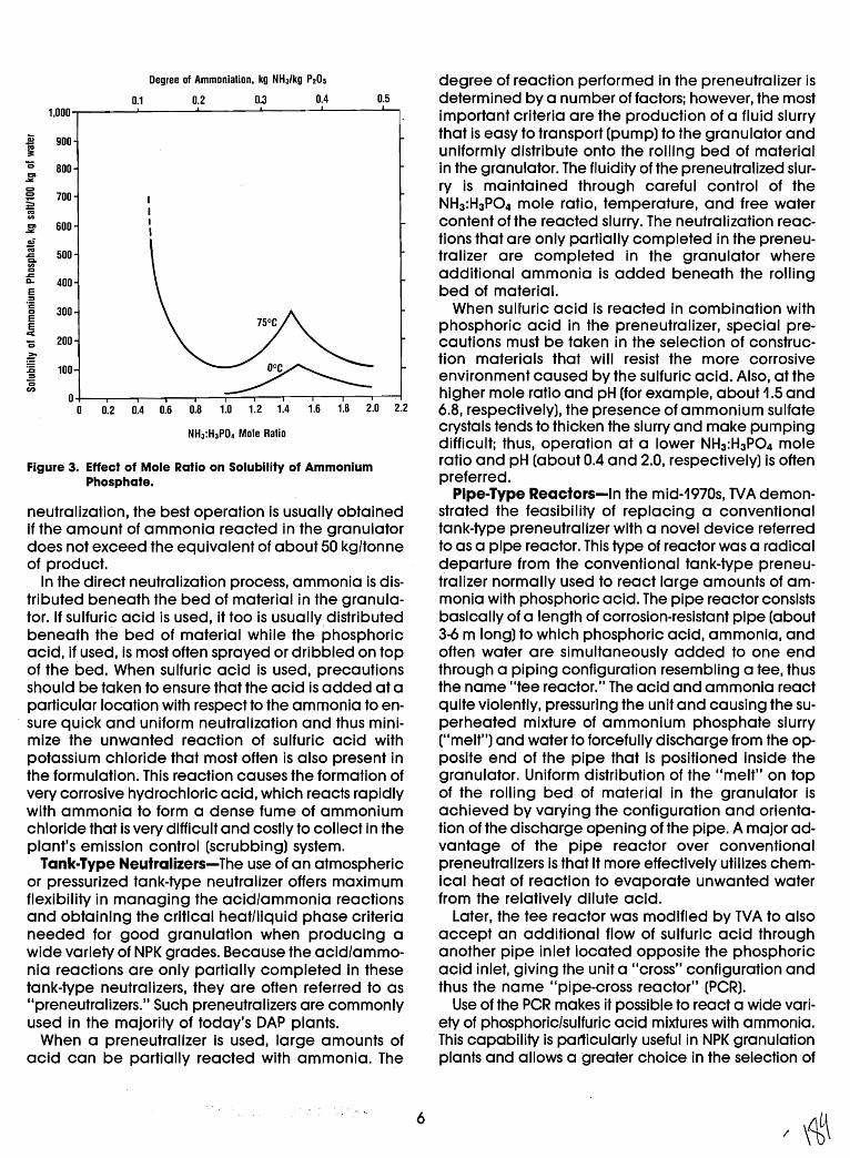
Degree of Ammoniation, kg NH3/kg P20S
0.1 0.2 0.3 0.4 0.51,000
S 900'"~'0 800CI
.:II:C)C) 700:;c;0
CI 600.:II:
a;';j
500.ca.00.cD- 400E='c
3000
EE<'0 200
~:E 100=0CI)
00 0.2 0.4 0.6 0.8 1.0 1.2 1.4 1.6 1.8 2.0 2.2
NH3:H3P04 Mole Ratio
Figure 3. Effect of Mole Ratio on Solubility of AmmoniumPhosphate.
neutralization, the best operation is usually obtainedif the amount of ammonia reacted in the granulatordoes not exceed the equivalent of about 50 kg/tonneof product.
In the direct neutralization process, ammonia is distributed beneath the bed of material in the granulator. If sulfuric acid is used, it too is usually distributedbeneath the bed of material while the phosphoricacid, if used, is most often sprayed or dribbled on topof the bed. When sulfuric acid is used, precautionsshould be taken to ensure that the acid is added at aparticular location with respect to the ammonia to ensure quick and uniform neutralization and thus minimize the unwanted reaction of sulfuric acid withpotassium chloride that most often is also present inthe formulation. This reaction causes the formation ofvery corrosive hydrochloric acid, which reacts rapidlywith ammonia to form a dense fume of ammoniumchloride that is very difficult and costly to collect in theplant's emission control (scrubbing) system.
Tank-Type Neutralizers-The use of an atmosphericor pressurized tank-type neutralizer offers maximumflexibility in managing the acid/ammonia reactionsand obtaining the critical heat/liquid phase criterianeeded for good granulation when producing awide variety of NPK grades. Because the acid/ammonia reactions are only partially completed in thesetank-type neutralizers, they are often referred to as"preneutralizers." Such preneutrallzers are commonlyused in the majori'ly of today's DAP plants.
When a preneutralizer is used, large amounts ofacid can be partially reacted with ammonia. The
6
degree of reaction performed in the preneutralizer isdetermined by a number of factors; however, the mostimportant criteria are the production of a fluid slurrythat is easy to transport (pump) to the granulator anduniformly distribute onto the rolling bed of materialin the granulator. The fluidity of the preneutralized slurry is maintained through careful control of theNH3 :H3P04 mole ratio, temperature, and free watercontent of the reacted slurry. The neutralization reactions that are only partially completed in the preneutralizer are completed in the granulator whereadditional ammonia is added beneath the rollingbed of material.
When suUuric acid is reacted in combination withphosphoric acid in the preneutralizer, special precautions must be taken in the selection of construction materials that will resist the more corrosiveenvironment caused by the sulfuric acid. Also, at thehigher mole ratio and pH (for example, about 1.5 and6.8, respectively), the presence of ammonium sul'fatecrystals tends to thicken the slurry and make pumpingdifficult; thus, operation at a lower NH3 :H3P04 moleratio and pH (about 0.4 and 2.0, respectively) is oftenpreferred.
Pipe-Type Reactors-In the mid-1970s, TVA demonstrated the feasibili'ly of replacing a conventionaltank-type preneutrallzer with a novel device referredto as a pipe reactor. This type of reactor was a radicaldeparture from the conventional tank-type preneutralizer normally used to react large amounts of ammonia with phosphoric acid. The pipe reactor consistsbasically of a length of corrosion-resistant pipe (about3-6 m long) to which phosphoric acid, ammonia, andoften water are simultaneously added to one endthrough a piping configuration resembling a tee, thusthe name lItee reactor." The acid and ammonia reactquite violently, pressuring the unit and causing the superheated mixture of ammonium phosphate slurry("melt") and water to forcefully discharge from the opposite end of the pipe that is positioned inside thegranulator. Uniform distribution of the llmelt" on topof the rolling bed of material in the granulator isachieved by varying the configuration and orientation of the discharge opening of the pipe. A major advantage of the pipe reactor over conventionalpreneutrallzers is that it more effectively utilizes chemical heat of reaction to evaporate unwanted waterfrom the relatively dilute acid.
Later, the tee reactor was modified by TVA to alsoaccept an additional flow of sulfuric acid throughanother pipe inlet located opposite the phosphoricacid inlet, giving the unit a lIcross" configuration andthus the name "pipe-cross reactor" (PCR).
Use of the PCR makes it possible to react a wide variety of phosphoric/sulfuric acid mixtures with ammonia.This capability is par1icularly useful in NPK granulationplants and allows a greater choice in the selection of
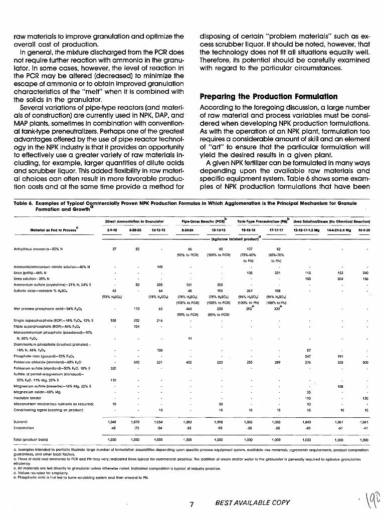
raw materials to improve granulation and optimize theoverall cost of production.
In general, the mixture discharged from the PCR doesnot require further reaction with ammonia in the granulator. In some cases, however, the level of reaction in'the PCR may be altered (decreased) to minimize theescape of ammonia or to obtain improved granulationcharacteristics of the "melt" when it is combined withthe solids in the granulator.
Several variations of pipe-type reactors (and materials of construction) are currently used in NPK, DAP, and'MAP plants, sometimes in combination with conventional tank-type preneutralizers. Perhaps one of the greatestadvantages offered by the use of pipe reactortechnology in the NPK industry is that it provides an opportunityto effectively use a greater variety of raw materials including, for example, larger quantities of dilute acidsand scrubber liquor. This added flexibility in raw material choices can often result in more favorable production costs and at the'same time provide a method for
disposing of certain "problem materials" such as excess scrubber liquor. It should be noted, however, thatthe technology does not fit all situations equally well.Therefore, its potential should be carefully examinedwi'th regard to the particular circumstances.
Preparing the Production FormulationAccording to the foregoing discussion, a large numberof raw material and process variables must be considered when developing NPK production formulations.As with the operation of an NPK plant, formulation toorequires a considerable amount of skill and an elementof "art" to ensure that the particular formulation willyield the desired results in a given plant.
A given NPK fertilizer can be formula1'ed in many waysdepending upon the available raw materials andspecific equipment system. Table 6 shows some examples of NPK production formulations that have been
Table 6. Examples of Typical Commercially Proven NPK Production Formulas in Which Agglomeration Is the Principal Mechanism for GranuleFormation and Growtha
PIpe-Cross Reactor (PCR)b b
Direct Ammonlatlon In Granulator Tank·Type Preneutrallzer (PNJ Urea Solution/Steam (No Chemical Reaction)
Material as Fed to Processc
3·9·18 5-20·20 13·13·13 8-24-24 13·13·13 15-15·15 17·17·17 12·12·17·1.2 Mg 14-6·21·2.4 Mg 16·0·30---d
•••---••--••--.-.---------.---- (kg/tonne finished product) ----Anhydrous ammonla-82% N 37 52 66 85 127 82
(90% to PCR) (100% to PCR) (75%-80% (65%-70%
to PN) to PN)
Ammonia/ammonium nitrate solution-46% N 145
Urea (prills)-46% N 105 231 115 153 240
Urea solution-35% N 155 204 156
Ammonium sulfate (crystalllne)-21% N, 24% S 50 205 121 300
Sulfuric acid-variable % H2SO4 63 64 40 192 261 108
(93% H2SO4) (78% H2SO4) (78% H2SO4) (78% H2SO4) (96% H2SO4) (96% H2SO4)
(100% to PCR) (100% to PCR) (100% to PN) (100%toPN)
Wet process phosphoric acld-54% P20 S 170 63 443 250 292e
330e
(90% to PCR) (85% to PCR)
Single superphosphate (ROP)-18% P20 S, 12% S 508 332 216
Triple superphosphate (ROP)-46% P20s 124
Monoammonlum phosphate (powdered)-10%
N, 50% P20 S 11
Dlammonium phosphate (crushed.granules)-
18% N, 46% P20 S 130 87
Phosphate rock (ground)-32% P20 S 247 191
Potassium chloride (standard)-60% K20 342 221 402 223 255 289 276 353 500
Potassium sulfate (standard)-50% K20, 18% S 320
Sulfate of potash-magnesium (standard)-
22% K20, 11% Mg, 22% S 110
Magnesium sulfate (kleserlte)-16% Mg, 22% S 150
Magnesium oxlde-50% Mg 25
Insoluble binder 110 130
Micronutrient mix (various nutrients as reqUired) 10 30 10
Conditioning agent (coating on product) 10 10 15 15 15 10 15
Subtotal 1,048 1,070 1,054 1,083 1,090 1,055 1,055 1,040 1,061 1,041
Evaporation -48 ·70 -54 ·83 -90 -55 -55 -40 ·61 -41
Total (product basis) 1,000 1,000 1,000 1,000 1,000 1,000 1,000 1,000 1,000 1,000
a. Examples Intended to partially Illustrate large number of formulation possibilities depending upon specific process equipment system, available raw materials, agronomic requirements, product compositionguarantees, and other local factors,b. Flows of acid and ammonia to PCR and PN may vary; Indicated flows typical for commercial practice. The addition of steam and/or water to the granulator Is generally required to optimize granulationefficiency.c. All materials are fed directly to granulator unless otherwise noted. Indicated composition Is typical of Industry practice.d. Values rounded for simplicity.e. Phosphoric acid Is first fed to fume scrubbing system and then onward to PN.
7 BEST AVAILABLE COpy
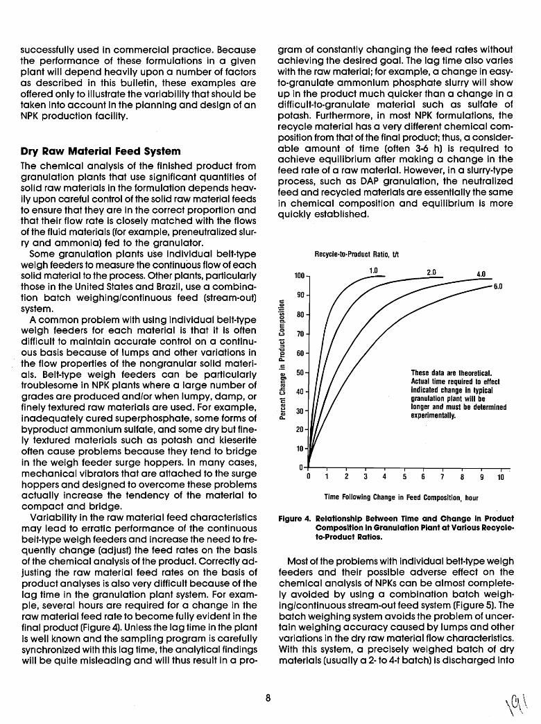
Figure 4. Relationship Between Time and Change in ProductComposition In Granulation Plant at Various Recycle·to·Product Ratios.
Most of the problems with individual belt-type weighfeeders and their possible adverse effect on thechemical analysis of NPKs can be almost completely avoided by using a combination batch weighing/continuous stream-out feed system (Figure 5). Thebatch weighing system avoids the problem of uncertain weighing accuracy caused by lumps and othervariations in the dry raw material flow characteristics.With this system, a precisely weighed batch of drymaterials (usually a 2- to 4-1' batch) is discharged into
gram of constantly changing the feed rates withoutachieving the desired goal. The lag time also varieswith the raw material; for example, a change in easyto-granulate ammonium phosphate slurry will showup in the product much quicker than a change in adifficult-to-granulate material such as sulfate ofpotash. Furthermore, in most NPK formulations, therecycle material has a very different chemical composition from that of the final product; thus, a considerable amount of time (often 3-6 h) is required toachieve equilibrium after making a change in thefeed rate of a raw material. However, in a slurry-typeprocess, such as DAP granulation, the neutralizedfeed and recycled materials are essentially the samein chemical composition and equilibrium is moreqUickly established.
6.0
2.0
These data are theoretical.Actual time required to effectindicated change in typicalgranulation plant will belonger and must be determinedexperimentally.
1.0
2 3 4 5 6 7 8 9 10
Time Following Change in Feed Composition, hour
Recycle-to-Product Ratio, Ut
90
100
c~.c;; 800CI.E0
70uc::;='C
600
It.:
50Q)
CICRJ
.s::. 40uCQ)
,~ 30Q)
~
20
10
00
successfully used in commercial practice. Becausethe performance of these formulations in a givenplant will depehd heavily upon a number of factorsas described in this bulletin, these examples areoffered only to illustrate the variabili'ly that should betaken into account in the planning and design of anNPK production facility.
Dry Raw Material Feed SystemThe chemical analysis of the finished product fromgranulation plants that use significant quantities ofsolid raw materials in the formulation depends heavily upon careful control of the solid raw material feedsto ensure that they are in the correct proportion andthat their flow rate is closely matched with the flowsof the fluid materials (for example, preneutrallzed slurry and ammonia) fed to the granulator.
Some granulation plants use individual belt-typeweigh feeders to measure the continuous flow of eachsolid material to the process. Other plants, particularlythose in the United States and Brazil, use a combination batch weighing/continuous feed (stream-out)system.
A common problem with using individual belt-typeweigh feeders for each material is that it is oftendifficult to maintain accurate control on a continuous basis because of lumps and other variations inthe flow properties of the nongranular solid materials. Belt-type weigh feeders can be particularlytroublesome in NPK plants where a large number ofgrades are produced and/or when lumpy, damp, orfinely textured raw materials are used. For example,inadequately cured superphosphate, some forms ofbyproduct ammonium sulfate, and some dry but finely textured materials such as potash and kieseriteoften cause problems because they tend to bridgein the weigh feeder surge hoppers. In many cases,mechanical vibrators that are a11ached to the surgehoppers and designed to overcome these problemsactually increase the tendency of the material tocompact and bridge.
Variability in the raw material feed characteristicsmay lead to erratic performance of the continuousbelt-type weigh feeders and increase the need to frequently change (adjust) the feed rates on the basisof the chemical analysis of the product. Correctly adjusting the raw material feed rates on the basis ofproduct analyses is also very difficult because of thelag time in the granulation plant system. For example, several hours are required for a change in theraw material feed ra1'e to become fully evident in thefinal product (Figure 4). Unless the lag time in the plantis well known and the sampling program is carefullysynchronized with this lag time, the analytical findingswill be quite misleading and will thus result in a pro-
8
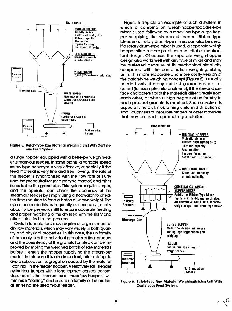
Figure 5. Batch-Type Raw Material Weighing Unit With Continuous Feed System.
To GranulationProcess
SURGE HOPPERMass flow design minimizesconing-type segregation andbridging.
FEEDERContinuous stream-outweigh feeder.
COMBINATION WEIGHHOPPER/MIXER
-+-r-I-..,....&-r-I..,..~~ Paddle- or Ribbon-Type Mixer.Typically 2- to 4-tonne batch size.An alternative could be a separateweigh hopper and drum-type mixer.
(...--""[IISCHARGE GATES~ -=- ~_ Controlled manually
or automatically.
c=::J
IndicatorRecorder
Raw Materials
~----l l---H-OLDING HOPPERS
Typically six in aCluster, each having 5- to10-tonne capacity.Also smallerhoppers for minorconstituents, if needed.
Figure 6. Batch-Type Raw Material Weighing/Mixing Unit WithContinuous Feed System.
c:::::::J
IndicatorRecorder
I . "'--.-/
L-----KDischarge Gate
Figure 6 depicts an example of such a system inwhich a combination weigh-hopper/paddle-typemixer is used, followed by a mass flow-type surge hopper supplying the stream-out feeder. Ribbon-typeblenders or rotary drum-type mixers can also be used.If a rotary drum-type mixer is used, a separate weighhopper offers a more practical and reliable mechanical design. Of course, the separate weigh-hopperdesign also works well with any type of mixer and maybe preferred because of its mechanical simplicitycompared with the combination weighing/mixingunits. This more elaborate and more costly version ofthe batch-type weighing concept (Figure 6) is usuallyneeded only if many nutrient guarantees are reqUired (for example, micronutl'ients), i'f the size and surface characteristics of the materials differ greatly fromeach other, or when a high degree of uniformity ineach product granule is required. Such a system isespecially helpful.ln obtaining uniform distribution ofsmall quantities of insoluble binders or other materialsthat may be used to promote granulation.
HOLDING HOPPERSTypically six in acluster, each having 5- to10-tonne capacity.Also smallerhoppers for minorconstituents, if needed.
WEIGH HOPPERTypically 2· to 4-tonne batch size.
To GranulationProcess
SURGE HOPPERMass flow design minimizesconing-type segregation andbridging.
DISCHARGE GATES#" Controlled !"anually(f or automatically.
FEEDERContinuous stream-outweigh feeder.
Raw Materials-J
c:::::::::J
IndicatorRecorder
Discharge Gate ----..:"""-/
III1. •
c:::::::::J
IndicatorRecorder
a surge hopper equipped with a belt-type weigh feeder (stream-out feeder). In some plants, a variable speedscrew-type conveyor is very effective, especially if thefeed material is very fine and free flowing. The ra1'e ofthis feeder is synchronized with the flow rate of slurryfrom the preneutralizer (or pipe-type reactor) and otherfluids fed to the granulator. This system is quite simple,and the operator can check the accuracy of thestream-out feeder by simply using a stopwatch to checkthe time required to feed a batch of known weight. Theoperator can do this as frequently as necessary (usuallyabout twice per work shift) to ensure accurate feedingand proper matching of the dry feed with the slurry andother fluids fed to the process.
Certain formulations may require a large number ofdry raw materials, which may vary widely in both quantity and physical properties. In this case, the uni'formi'lyof the analysis of the individual granules of final productand the consistency of the granulation step can be improved by mixing the weighed batch of raw materialsbefore it enters the hopper supplying the stream-outfeeder. In this case it is also important, after mixing, toavoid subsequent segregation caused by the material"coning" in the feeder hopper. A relatively tall, slendercylindrical hopper with a long tapered conical bottom,described in the literature as a "mass flow hopper," willminimize "coning" and ensure uniformity of the material entering the stream-out feeder.
9
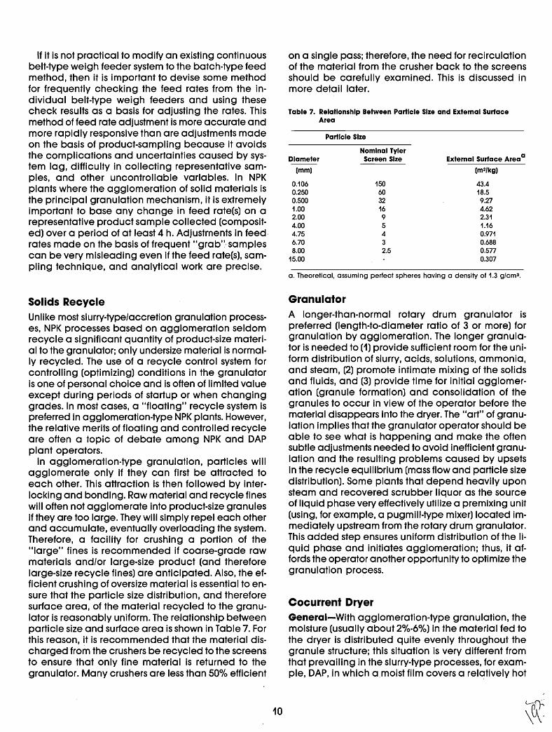
a. Theoretical, assuming perfect spheres having a density of 1.3 g/cm3 •
Table 7. Relationship Between Particle Size and External SurfaceArea
on a single pass; therefore, the need for recirculationof the material from the crusher back to the screensshould be carefully examined. TI1is is discussed inmore deta iI later.
If it is not practical to modify an existing continuousbelt-type weigh feeder system to the batch-type feedmethod, then it is important to devise some methodfor frequently checking the feed rates from the individual belt-type weigh feeders and using thesecheck results as a basis for adjusting the rates. Thismethod of feed rate adjustment is more accurate andmore rapidly responsive than are adjustments madeon the basis of product-sampling because it avoidsthe complications and uncertainties caused by system lag, difficulty in collecting representative samples, and other uncontrollable variables. In NPKplants where the agglomeration of solid materials isthe principal granulation mechanism, it is extremelyimportant to base any change in feed rate(s) on arepresentative product sample collected (composited) over a period of at least 4 h. Adjustments in feed,rates made on the basis of frequent IIgrab'" samplescan be very misleading even if the feed rate(s), sampling technique, and analytical work are precise.
Diameter
(mm)
0.1060.2500.5001.002.004.004.756.708.00
15.00
Particle Size
Nominal TylerScreen Size
15060321695432.5
External Surface Areaa
(m2/kg)
43.418.59.274.622.311.160.9710.6880.5770.307
Solids RecycleUnlike most slurry-type/accretion granulation processes, NPK processes based on agglomeration seldomrecycle a significant quantity of product-size material to the granulator; only undersize material is normally recycled. The use of a recycle control system forcontrolling (optimizing) conditions in the granulatoris one of personal choice and is often of limited valueexcept during periods of startup or when changinggrades. In most cases, a IIfloating" recycle system ispreferred in agglomeration-type NPK plants. However,the relative merits of floating and controlled recycleare often a topic of debate among NPK and DAPplant operators.
In agglomeration·type granulation, particles willagglomerate only if they can first be a1tracted toeach other. This a1traction is then followed by interlocking and bonding. Raw material and recycle fineswill often not agglomerate into product-size granulesif they are too large. They will simply repel each otherand accumulate, eventually overloading the system.Therefore, a facility for crushing a portion of theIIlarge" fines is recommended if coarse-grade rawmaterials and/or large-size product (and thereforelarge-size recycle fines) are anticipated. Also, the efficient crushing of oversize material is essential to ensure that the particle size distribution, and thereforesurface area, of the material recycled to the granulator is reasonably uniform. The relationship betweenparticle size and surface area is shown in Table 7. Forthis reason, it is recommended that the material discharged from the crushers be recycled to the screensto ensure that only fine material is returned to thegranulator. Many crushers are less than 50% efficient
10
GranulatorA longer-than-normal rotary drum granulator ispreferred (Iength-to-diameter ratio of 3 or more) forgranulation by agglomeration. The longer granulator is needed to (1) provide sufficient room for the uniform distribution of slurry, acids, solutions, ammonia,and steam, (2) promote intimate mixing of the solidsand fluids, and (3) provide time for initial agglomeration (granule formation) and consolidation of thegranules to occur in view of the operator before thematerial disappears into the dryer. The lIal1" of granulation implies that the granulator operator should beable to see what is happening and make the oftensubtle adjustments needed to avoid inefficient granulation and the resulting problems caused by upsetsin the recycle equilibrium (mass flow and particle sizedistribution). Some plants that depend heaVily uponsteam and recovered scrubber liquor as the sourceof liquid phase very effectively utilize a premixing unit(using, for example, a pugmill-type mixer) located immediately upstream from the rotary drum granulator.This added step ensures uniform distribution of the liquid phase and initiates agglomeration; thus, it affords the operator another opportunity to optimize thegranulation process.
Cocurrent DryerGeneral-With agglomeration-type granulation, themoisture (usually about 2%-6%) in the material fed tothe dryer is distributed quite evenly throughout thegranule structure; this situation is very different fromthat prevailing in the slurry-type processes, for example, DAP, in which a,moist film covers a rel~1'ively hot
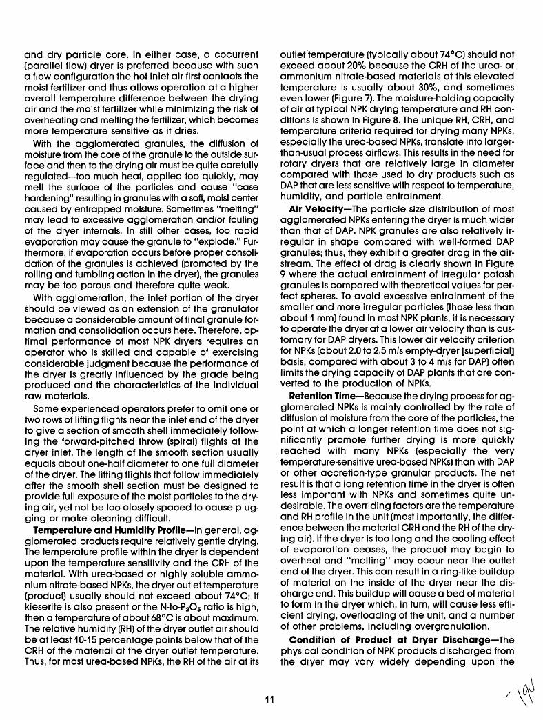
and dry particle core. In either case, a cocurrent(parallel flow) dryer is preferred because with sucha flow configuration the hot inlet air first contacts themoist fertilizer and thus allows operation at a higheroverall temperature difference between the dryingair and the moist fertilizer while minimizing the risk ofoverheating and melting the fertilizer, which becomesmore temperature sensitive as it dries.
With the agglomerated granules, the diffusion ofmoisture from the core of the granule to the outside surface and then to the drying air must be quite carefullyregulated-too much heat, applied too quickly, maymelt the surface of the particles and cause lIcasehardening" resulting in granules with a soft, moist centercaused by entrapped moisture. Sometimes lImelting"may lead to excessive agglomeration and/or foulingof the dryer internals. In still other cases, too rapidevaporation may cause the granule to lIexplode:' Furthermore, if evaporation occurs before proper consolidation of the granules is achieved (promoted by therolling and tumbling action in the dryer), the granulesmay be too porous and therefore quite weak.
With agglomeration, the inlet portion of the dryershould be viewed as an extension of the granulatorbecause a considerable amount of final granule formation and consolidation occurs here. Therefore, optimal performance of most NPK dryers requires anoperator who is skilled and capable of exercisingconsiderable judgment because the performance ofthe dryer is greatly influenced by the grade beingproduced and the characteristics of the individualraw materials.
Some experienced operators prefer to omit one ortwo rows of lifting flights near the inlet end of the dryerto give a section of smooth shell immediately following the forward-pitched throw (spiral) flights at thedryer inlet. The length of the smooth section usuallyequals about one-half diameter to one full diameterof the dryer. The lifting flights that follow immediatelyafter the smoo.th shell section must be designed toprovide full exposure of the moist particles to the drying air, yet not be too closely spaced to cause plugging or make cleaning difficult.
Temperat'ure and Humidity Profile-In general, agglomerated products require relatively gentle drying.The temperature profile within the dryer is dependentupon the temperature sensitivity and the CRH of thematerial. With urea-based or highly soluble ammonium nitrate-based NPKs, the dryer outlet temperature(product) usually should not exceed about 74°C; i'fkieserite is also present or the N-to-P20 S ratio is high,then a temperature of about 68°C is about maximum.The relative humidity (RH) of the dryer outlet air shouldbe at least10-15 percentage points below that of theCRH of the material at the dryer outlet temperature.Thus. for most urea-based NPKs, the RH of the air at its
11
outleftemperature (typically about 74°C) should notexceed about 20% because the CRH of the urea- orammonium nitrate-based materials at this elevatedtemperature is usually about 30%, and sometimeseven lower (Figure 7). The moisture-holding capacityof ail' at typical NPK drying temperature and RH conditions is shown in Figure 8. The unique RH, CRH, andtemperature criteria required for drying many NPKs,especially the urea-based NPKs, translate into largerthan-usual process airflows. This results in the need forrotary dryers that are relatively large in diametercompared with those used to dry products such asDAP that are less sensitive with respect to temperature,humidi'ly, and particle entrainment.
Air Velocity-The particle size distribution of mostagglomerated NPKs entering the dryer is much widerthan that of DAP. NPK granules are also relatively irregular in shape compared with well-formed DAPgranules; thus, they exhibit a greater drag in the airstream. The effect of drag is clearly shown in Figure9 where the actual entrainment of irregular potashgranules is compared with theoretical values for perfect spheres. To avoid excessive entrainment of thesmaller and more irregular particles (those less thanabout 1 mm) found in most NPK plants, it is necessaryto operate the dryer at a lower air velocity than is customary for DAP dryers. This lower air velocity criterionfor NPKs (about 2.0 to 2.5 m/s empty-d.ryer [superficial]basis, compared with about 3 to 4 m/s for DAP) oftenlimits the drying capacity of DAP plants that are converted to the production of NPKs.
Retention Time-Because the drying process for agglomerated NPKs is mainly controlled by the rate ofdiffusion of moisture from the core of the particles, thepoint at which a longer retention time does not significantly promote further drying is more quickly
. reached with many NPKs (especially the verytemperature-sensitive urea-based NPKs) than with DAPor other accretion-type granular products. The netresul1' is that a long retention time inthe dryer is oftenless important with NPKs and sometimes quite undesirable. The overriding factors are the temperatureand RH profile in the unit (most importantly, the di'fference between the material CRH and the RH of the drying air). If the dryer is too long and the cooling effectof evaporation ceases, the product may begin tooverheat and "melting" may occur near the outletend of the dryer. This can result in a ring-like buildupof material on the inside of the dryer near the discharge end. This bUildup will cause a bed of materialto form in the dryer which, in turn, will cause less efficient drying, overloading of the unit, and a numberof other problems, including overgranulation.
Condition of Product at Dryer Discharge-Thephysical condition of NPK products discharged fromthe dl'yer may vary widely depending upon the
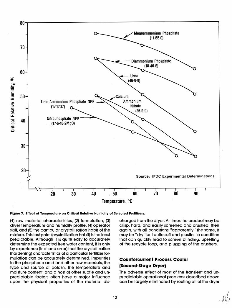
80---------------------------------,
70
60
>~"'C
§ 50:::z:Q)
>~mQ)
a::m 40c.:I~.~
c.,:)
30
20
Urea-Ammonium Phosphate NPK(17-17-:17)
Nitrophosphate NPK(17-6-18-2MgO)
Monoammonium Phosphate(11-55-0)
CalciumAmmonium
Nitrate(26-0-0)
Source: IFDe Experimental Determinations.
20 30 40 50
Temperature, °C
60 70 80 90
Figure 7. Effect of Temperature on Critical Relative Humidity of Selected Fertilizers.
(1) raw material characteristics, (2) formulation, (3)dryer temperature and humidity profile, (4) operatorskill, and (5) the particular crystallization habit of themixture. This last point (crystallization habit) is the leastpredictable. Although it is quite easy to accuratelydetermine the expected free water content, it is onlyby experience (trial and error) that the crystallization(hardening) characteristics of a particular fertilizer formulation can be accurately determined. Impuritiesin the phosphoric acid and other raw materials, thetype and source of potash, the temperature andmoisture content, and a host of other subtle and unpredictable factors often have a major influenceupon the physical properties of the material dis-
12
charged from the dryer. At times the product may becrisp, hard, and easily screened and crushed; thenagain, with all conditions "apparently" the same, itmay be "dry" but quite soft and plastic-a conditionthat can quickly lead to screen blinding, upsettingof the recycle loop, and plugging of the crushers.
Countercurrent Process Cooler(Second-Stage Dryer)The adverse effect of most of the transient and unpredictable operational problems described abovecan be largely eliminated by routing all of the dryer
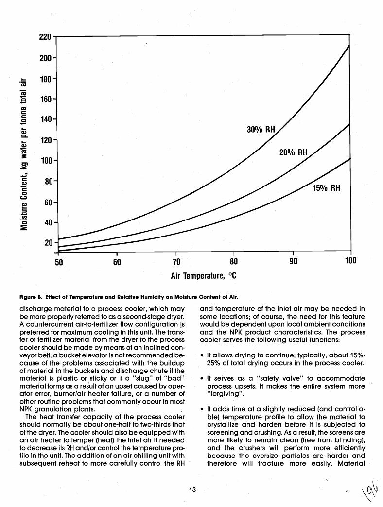
220
200
- 180·co~- 160c-CI)cc 140c--CI)CL
120-CI)-~3: 100en
..::.::-c 80CI)-cc(.)
CI) 60-:::J-.~ 40c:2:
20
50 60 70 80 90 100
Air Temperature, °C
Figure 8. Effect of Temperature and Relative Humidity on Moisture Content of Air.
discharge material to a process cooler, which maybe more properly referred to as a second-stage dryer.A countercurrent air-to-fertilizer flow configurationjspreferred for maximum cooling in this unit. The transfer of fertilizer material from the dryer to the processcooler should be made by means of an inclined conveyor belt; a bucket elevator is not recommended because of the problems associated with the buildupof material in the buckets and discharge chute if thematerial is plastic or sticky or if a "slug" of "bad"material forms as a result of an upset caused byoperator error, burner/air heater failure, or a number ofother routine problems that commonly occur in mostNPK granulation plants.
The heat transfer capacity of the process coolershould normally be about one-hal" to tw~-thirds thatof the dryer. The cooler should also be eqUipped withan air heater to temper (heat) the inlet air if neededto decrease its RH and/or control the temperature profile in the unit. The addition of an air chilling unit withsubsequent reheat to more carefully control the RH
13
and temperature of the inlet air may be needed insome locations; of course, the, need for this featurewould be dependent upon local ambient conditionsand the NPK product characteristics. The processcooler serves the following useful functions:
• It allows drying to continue; typically, about 15%
25% of total drying occurs in the process cooler.
• It serves as a "safety valve" to accommodateprocess upsets. It makes the entire system more"forgiving".
• It adds time at a slightly redlJCed (and controllable) temperature profile to allow the material tocrystallize and harden before it is subjected toscreening and crushing. As a result, the screens aremore likely to remain clean (free from blinding),and the crushers will perform more efficientlybecause the oversize particles are harder andtherefore will fracture more easily. Material
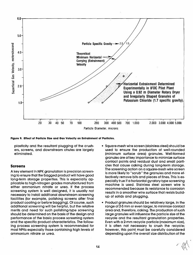
:.:·.::~rHorizontal Entrainment DeterminedExperimentally in IFDC Pilot PlantUsing a 0.92 m Diameter Rotary Drye.rand Irregularly Shaped Granules ofPotassium Chloride (1.7 specific gravi'ly).
5.0
"Cc:0(.)Q)II)
4.0~ TheoreticalQ)
Minimum HorizontaliiiE Carrying (Entrainment)~ Velocity'(30 3.0"iii::>II)
~
e.,:,
~"(3- 2.0Q;0.~
en
1.0
6.0..,...----------------------------r----r---------,
20 30 40 50 70 100 200 300 400 500 700 1.000
Particle Diameter. microns
2.000 3.000 4.000 5.000
Figure 9. Effect of Particle Size and Gas Velocity on Entrainment of Particles.
plasticity and the resultant plugging of the crushers, screens, and downstream chutes are largelyeliminated.
ScreensA key element in NPK granulation is precision screening to ensure that the bagged product will have goodlong-term storage properties. This is especially applicable to high-nitrogen grades manufactured fromeither ammonium nitrate or urea. If the processscreening system Is well designed, it is usually notnecessary to install additional downstream screeningfacilities (for example, polishing screens after finalproduct cooling or before bagging). Of course, suchadditional screening will be helpfUl, but the relativemerits and need for such polishing-type screeningshould be determined on the basis of the design andperformance of the basic process screening systemand the specific product characteristics. The following process screening system Is recommended formost NPKs especially those containing high levels ofammonium nitrate or urea.
• Square-mesh wire screen (stainless steel) should beused to ensure the production of well-rounded(minimum surface area) granules. Well-formedgranules are of key importance to minimize surfacecontact points and residual dust and small particles that cause caking during long-term storage.The screening action on a square-mesh wire screenis more likely to "scrub" the granules and more effectively remove bits and pieces of fines. This is especially true if a horizontal gyratory-type screeningmachine is used. Stainless steel screen wire isrecommended because its resistance to corrosionresults in a smoother wire surface that resists buildup of solids and plugging.
• Product granules should be relatively large, in therange of 2-5 mm or even larger, to minimize contactarea and, therefore, caking. The production of suchlarge granules will influence the particle size of therecycle and the resultant granulation properties.Even with a 2-mm recycle particle (maximum size),it is often not necessary to crush the recycle;however, this point. must be carefully considereddepending upon the overall size distribution of the
14
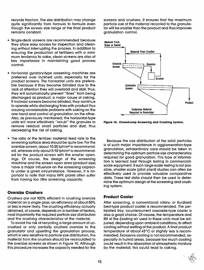
recycle fraction. The size distribution may changequite significantly from formula to formula eventhough the screen size range of the final productremains constant.
• Single-deck screens are recommended becausethey allow easy access for inspection and cleaning without interrupting the process. In addition toensuring the production of fertilizers with a minimum tendency to cake, clean screens are also ofkey importance In maintaining good processcontrol.
• Horizontal gyratory-type screening machines arepreferred over inclined units, especially for theproduct screens. The horizontal units are preferable because if they become blinded due to thelack of attention they will overload and stall; thus,they will automatically prevent "fines" from beingdischarged as product, a major cause of caking.If inclined screens become blinded, they continueto operate while discharging fines with product thuscausing considerable problems with caking on theone hand and control of granulation on the other.Also, as previously mentioned, the horizontal-typeunits will more effectively "scrub" the granules toremove residual small particles and dust, thusdecreasing the risk of caking.
• The ratio of the fertilizer material feed rate to thescreening surface area should be quite low. For theoversize screen, about 10-20 tph/m2 is recommended, whereas only about 5-10 tph/m2 is recommended for the product screen with the smaller openings. Of course, the design of the screeningmachine and the screen open area (product size)have a major influence on the screening capacity under a given circumstance. However, it is important to note that many NPK plants often sufferfrom having too little screening capacity.
Oversize CrushersCrushers are not 100% efficient in crushing oversizematerial on a single pass; an efficiency of about 50%or less is more likely. The crushing efficiency actuallyobtained, of course, depends on a number of factors,most importantly the reqUired particle size distributionand the crushing characteristics of the material.
To avoid the risk of recycling a large amount of uncrushed or only partially crushed oversize to thegranulator and upsetting the granulation process,which is very sensitive to particle size distribution, thematerial from the crushers should be recirculated tothe oversize screens as shown in Figure 10. Althoughthis procedure increases the capacity needed for the
15
screens and crushers, it ensures that the maximumparticle size of the material recycled to the granulator will be smaller than the product and thus improvesgranulation control.
Material FromDryer or Cooler
Material From Crusher
Oversize r"'""'-----_Screen
Undersize r--------..Screen '-t-------,
Product
Undersize MaterialRecycled to Granulator
Figure 10. Closed·l.oop Screening and Crushing System.
Because the size distribution of the solid particlesis of such major importance in agglomeration-typegranulation, extraordinary care should be taken indetermining the optimum particle size characteristicsrequired for good granUlation. This type of information is learned best through testing in commercialscale equipment. If such large-scale testing is not possible, smaller scale (pilot plant) studies can often beeffectively used to provide valuable comparativedata. These test data should then be used to determine the optimum design of the screening and crushing system.
Product CoolerAfter screening, a conventional rotary- or fluidizedbed-type product cooler is recommended. The perforated tray, countercurrent cascade-type cooler isalso a good choice. Of course, the temperature andRH of the ~oollng air used in these units must be adjusted, depending upon ambient conditions, to effectcooling without wetting of the prodUCt. A final producttemperature of about 43°C or slightly less is recommended. Excessive cooling is not recommended, especially in humid areas, because too much coolingcould result in the absorption of atmospheric moistureby the material; this could lead to caking.
Condil'ioningMany NPKs should be conditioned to add extra protection against caking. A kaolin-type clay is recommended. Usually about 0.5% -1.0% by weight is required;however, this depends heavily upon the NPK productcharacteristics and the properties of the clay. The benefitof using oil or wax to help bind the clay to the granulesis not always clear; the oil or wax does, however, helpto settle dust in bulk storage and bagging areas evenif it does not always fully adhere the clay to the granulesurface. If an oil-type binder is used, all conveyor beltsdownstream from the binder addition system should be"oil proof" to avoid ply separation and failure. Beltingmade from neoprene or polyvinyl chloride is not severelyaffected by oil-type binders or other organic-type conditioning agents.
The application of oil to NPKs, especially thoseproduced by agglomeration, is often. difficult because of the relatively unpredictable absorptioncharacteristics of the granules from one grade toanother. For those grades containing ammonium nitrate, especially in combination with potassium chloride, the use of oil should be avoided for safetyreasons. A more detailed discussion of the potentialsafety hazards of mixing organic materials withnitrate-containing fertilizers can be found in the Fertilizer Manual and the references cited therein.
The most effective way to add solid conditioningagents to granular fertilizers is by use of a speciallydesigned rotary drum application unit. The designparameters for such drums can also be found in theFertilizer Manual.
Storage and BaggingThe recommended, and usually most practical,product storage and bagging system for hygroscopic NPKs consists of (1) a relatively small humiditycontrolled bulk storage area (building) representingabout 1 to 2 days' production. This bulk storage areashould be divided according to the expected number of grades produced over a 1- to 2-day period; aminimum of two or three drive-in storage bays isrecommended. This small and segregated storagemethod will also gre(]tly facilitate changing of gradeswith a minimum of lost time. This method of bulkstorage before bagging will minimize, and usuallyeliminate, the accumulation of "grade change"products that are so far off specification that they cannot be shipped. After a brief period of storage in bulk(overnight or perhaps a day or two) to allow for initial"pile set" and to certify the analyses, the productshould be bagged in moistureproof bags. Baggingdirectly from the production unit or bulk storage offreshly made product in overhead bins is notrecommended.
16
The optimum bag construction for long-term storagein humid areas consists of an open-mouth bag fittedwith a loose polyethylene film liner thai' is at least 0.1mm thick. The outer jacket should be constructed ofwoven polypropylene or some other strong and durable material. The liner should be tied, and the outerjacket should be stitched. The stitching should notpenetrate the liner. Heat sealing of the liner is notrecommended because if precautions are not takensuch sealing usually entraps air that may result inpillow-shaped bags. Handling, especially stacking,such pillow-shaped bags is difficult. Venting entrapped air from such bags by piercing the film lineris a common practice but this should be avoided because such venting allows atmospheric moisture toseep into the bag, causing wetting and caking.
Process Plant DehumidificationIf hygroscopic NPKs are produced (especially thosecontaining urea) and the ambient relative humidityat the plant site is in excess of about 50% for more thanabout 8 consecutive hours on a routine basis, it is essential that the process plant bUilding (and bulkproduct storage building) be tightly enclosed andventilated with low-RH air. Furthermore, if the temperature inside these enclosed buildings is excessive,then it will be necessary to cool and dehumidify theair to maintain comfortable and safe working conditions at an acceptable RH that will prevent "wetting"of the plant and equipment. Excessive "wetting"caused by the hygroscopic fertilizer material and dustaccumulations will lead to excessive corrosion, electrical failures, safety problems (slippery floors andwalkways), and a number of adverse processproblems particularly with conveyor belt idlers, dustcollection systems, screens, and air handling systems.
Recommendations Specific to theProduction of NPKs Containing UreaUrea-based NPKs are among the granular fertilizersthat are most difficult to produce. On the basis of theforegoing general discussion and the particularcharacteristics of most urea-based NPKs, the criteriashown in the Appendix are recommended as a starting point for the basic design of a plant well suitedfor producing urea-based NPKs or other NPKs that exhibit similar characteristics such as excessive plasticiiy, low tolerance to elevated temperatures, and lowCRH. These recommended design features are alsoapplicable to the more tolerant NPKs. However, withthese more tolerant NPKs, more latitude in the designand:operating criteria may be allowed.

To Almosphere
Phosphoric AcidWater
Water
Noles:1. Shaded equipment items usually not included in conventional
ammonium phosphate (OAP/MAP) plants.2. Pipe·cross reactor (PCRl in addition to preneutralizer provides
maximum flexibility in formulating high acid·containing grades.3. Rotary or fluidized bed unil.4. Process plant building may have to be dehumidified depending
upon CRH of fertilizer and ambient relative humidity.
Conditioning AgentlClay & Oil Binder)
Vent
TransferConveyor(Bell·Typel
DustCollectors
LumpBreaker
Phosphoric Acid
Rotary Dryer
Recycle
Vent
Gas ScrubbingSystem
l
Air Heater
Preneutralizer(See Note 2)
B~l:~ ~~::: 11:11111_
[::~::I
Continuous TH.H~E .FFeed System EEE
,...------
............... Fuel
Solid Urea Vent to A-ir----
Water _IiJrber--
-fill~
Urea Solution/MeltPreparation System
Solid Matenals
Figure 11. Recommended Process Flow Diagram for Maximum flexibility in Producing Granular NPKs Based onAgglomeration.
A process flow diagram of an NPK granulationplant embodying ,the recommended fea1'ures isshown in Figure 11. Also indicated in Figure 11 arethe features that are most often missing in a plantdesi'gned primarily for the production of DAP/MAP.
Verification of Recommended PlantDesign and Operating Parameters
The recommended design and operatingparameters for NPK granulation plants described inthis bulletin are thought to be near optimum on thebasis of data obtained from a number of IFDC pilotplant-scale trials and experience with severalcommercial-scale operations. However,because notwo formulations (grades) or plants respond in exactly the same way to a given set of conditions, extrapolation and judgment are required when attemptingto 'setthe design basis for a "new" grade or plant.
ConclusionThe fundamentals of granule formation and processing for agglomerated NPK fertilizers differ markedlyfrom those for DAP/MAP fertilizers. For this reason, manywell-desig.'ned DAP/MAP plants experience difficultieswhen called upon to produce NPKs. The difficultiesare most pronounced when the NPKs contain urea orother temperature-sensitive and hygroscopic ingredients. The plant design and operating criteriadescribed in this bulletin are intended to guide thoseinvolved in planning new NPK plant projects ortrOUbleshooting and modifying existing units. Thisbulletin may also be used as a checklist during thevarious stages of project development to help ensurethat the special requirements for NPK plants are notoverlooked.
BEST AVAILABLE COpy
17
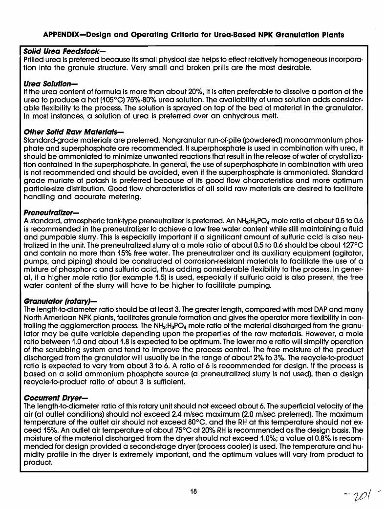
APPENDIX-Design and Operating Criteria for Urea-Based NPK Granulation Plants
Solid Urea Feedstock-. Prilled urea is preferred because its small physical size helps to effect relatively homogeneous incorpora
tion into the granule structure. Very small and broken prills are the most desirable.
Urea Solution-If the urea content of formula is more than about 20%, it is often preferable to dissolve a portion of theurea to produce a hot (105°C) 75%-80% urea solution. The availability of urea solution adds considerable flexibility to the process. The solution is sprayed on top of the bed of material in the granulator.In most instances, a solution of urea is preferred over an anhydrous melt.
Other Solid Raw Materials-Standard-grade materials are preferred. Nongranular run-of-pile (powdered) monoammonium phosphate and superphosphate are recommended. If superphosphate is used in combination with urea, itshould be ammoniated to minimize unwanted reactions that result in the release of water of crystallization contained in the superphosphate. In general, the use of superphosphate in combination with ureais not recommended and should be avoided, even if the superphosphate is ammoniated. Standardgrade muriate of potash is preferred because of its good flow characteristics and more optimumparticle-size distribution. Good flow characteristics of all solid raw materials are desired to facilitatehandling and accurate metering.
Preneutralizer-A standard, atmospheric tank-type preneutralizer is preferred. An NH3:H3P04 mole ratio of about 0.5 to 0.6is recommended in the preneutralizer to achieve a low free water content while still maintaining a 'fluidand pumpable slurry. This is especially important if a significant amount of sulfuric acid is also neutralized in the unit. The preneutralized slurry at a mole ratio of about 0.5 to 0.6 should be about 127°Cand contain no more than 15% free water. The preneutralizer and its auxiliary equipment (agitator,pumps, and piping) should be constructed of corrosion-resistant materials to facilitate the use of amixture of phosphoric and sulfuric acid, thus adding considerable 'flexibility to the process. In general, if a higher mole ratio (for example 1.5) is used, especially if sulfuric acid is also present, the freewater content of the slurry will have to be higher to facilitate pUITlping.
Granulator (rotaryJ-The length-te-diameter ratio should be at least 3. The greater length, compared with most DAP and manyNorth American NPK plants, facilitates granule formation and gives the operator more flexibility in controlling the agglomeration process. The NH3:H3P04 mole ratio of the material discharged from the granulator may be quite variable depending upon the properties of t.he raw materials. However, a moleratio between 1.0 and about 1.8 is expected to be optimum. The lower mole ratio will simplify operationof the scrubbing system and tend to improve the process control. The free moisture of the productdischarged from the granulator will usually be in the range of about 2% to 3%. The recycle-to-productratio is expected to vary from about 3 to 6. A ratio of 6 is recommended for design. If the process isbased on a solid ammonium phosphate source (a preneutralized slurry is not used), then a designrecycle-to-product ratio of about 3 is sufficient. .
Coc.urrent Dryer-The length-to-diameter ratio of this rotary unit should not exceed about 6. The superficial velocity of theair (at outlet conditions) should not exceed 2.4 m/sec maximum (2.0 m/sec preferred). The maximumtemperature of the outlet air should not exceed 80°C, and the RH at this temperature should not exceed 15%. An outlet air temperature of about 75°C at 20% RH is recommended as the design basis. Themoisture of the material discharged from. the dryer should not exceed 1.0%; a value of 0.8% is recommended for design provided a second-stage dryer (process cooler) is used. The temperature and humidity profile in the dryer is extremely important, and the optimum values will vary from product toproduct.
18 -Wi /'
Countercurrent Process Cooler-(Second-5tage Dryer}The length-to-diameter ratio of this unit should not be less than 6; 7 to 8 is preferred. The inlet air shouldbe tempered (heated) and/or conditioned to ensure that the RH is 60% or less. The superficial air velocity should not exceed 2.0 m/sec. The low velocity is recommended because of the relatively largeamount of minus 1.0 mm particles in the material. It is preferred that these small particles be removed(separated) by the screens rather thdn by the airflow/dust collection system. The unit should be designedto achieve a material (discharge) temperature of not more than about 54°C at a free moisture content of no more than 0.6%. Further cooling of the product fraction is performed in a separate operation.
.Screening-~ Single-deck horizontal gyratory-type units are recommended. The screen wire should be stainless steel
and of the square-mesh style. If inclined, electrically (or motor) vibrated screens are used, they shouldbe for oversize separation only, not for product screening. The hourly loading of the oversize screenshould not exceed about 20 t/m2, and the loading of the horizontal gyratory-type product screen shouldnot exceed 50% of this value (25%-30% preferred).
Oversize Crushers-Double rotor chainmill-type crushers or double row cage mills are preferred. The discharge assemblies of the mills should not be restricted and should be constructed of flexible rubber (conveyor belting) panels that can be flexed from the outside by an operator using a hammer. A flared-type dischargeassembly for the crushers is recommended to help avoid the accumulation of solids. The crushedoversize should be recycled to the oversize screen on a closed-loop basis to ensure that only the finematerial fraction from the screens is returned to the granulator as recycle.
Product Cooling-Either a rotary-drum or fluidized-bed unit is recommended. The single-pass, counter-current, cascadetype unit is also acceptable. The cooling unit should be located immediately ahead of the conditioning unit. The RH of the cooling air at inlet conditions shouJd not exceed 50%. The temperatureof the product discharged from the cooler should not exceed about 43°C. In all cases the temperature of the cooled product should be about 5°C above the average ambient temperature to avoidabsorption of atmospheric moisture on the surface of the material.
Conditioning-A standard rotary drum-type conditioning unit is recommended. Screw-type mixing units should beavoided as they tend to grind and break the product granules.
Bulk Storage and Process Plant Dehumidification-If ambient conditions normally exceed about 50% RH for extended periods (more than about 8-16h), provisions should be made to dehumidify the process plant and bulk storage buildings. Coolingand proper ventilation may also be necessary for worker comfort and safety. Adequate ventilationis especially important because all bUildings should be tightly constructed and closed to maintaina dry inside environment (RH of 40%-50%).
Bagging-The products should be bagged in moistureproof bags shortly after production. Direct bagging fromthe production unit is not recommended because off-specification product could inadvertently bebagged and because fleXibility is lost in handling product during grade-change periods. In addition, bag set (caking) is minimized if the fresh product is allowed to "pile set" for a short period of time.
19
Bibliography1. Achorn, F. P., and D. G. Salladay. 1976. liTVA's New
Pipe-Cross Reactor Process for Granular Ammonium Phosphates," Paper presented at AmericanChemical Society Meeting, San Francisco,California, U.S.A.
2. Chinal, P., C. DeBayeux, and J. F. Priat. 1986. IIDualPipe Reactor Process for DAP, NP, and NPKProduction," IN Proceedings of the 36th AnnualMeeting of the Fertilizer Industry Round Table, pp.30.
3. Fischbein, M., and A. M. Brown. 1988. IIHigh Quality Granular Ammonium Sulphate Production,"Paper presented at the International Fertilizer Industry Association, Limited, Conference, Edmonton, Canada.
4. Hemsley, J.D.C., and Francisco Roig. 1972. liTheManufacture of Granular Compound FertilizersBased on Urea as the Principal Source of Nitrogen," IN Proceedings of the ISMA Technical Conference held in Seville, Spain 20th to 24thNovember, 1972, International Superphosphateand Compound Manufacturers' Association Ltd.,London, England.
5. Hoffmeister, G., and C. P. Harrison. 1977. IIPhysicalProperties of Granular Urea-Based NP and NPKFertilizers," IN Proceedings of the 27th AnnualMeeting Fertilizer Industry Round Table, pp.162-171.
6. International Fertilizer Development Center. 1979.Fertilizer Manual. IFDCR-1 (also available from theUnited Nations Industrial Development Organization, Vienna, Austria), Muscle Shoals, Alabama,35662 U.S.A.
20
7. Medbery, J. L., and F. T. Nielsson. 1981. IIFundamentals of Granulation," IN Proceedings of the182nd American Chemical Society NationalMeeting, Paper No. 20, New York, New York, U.S.A.
8. Salladay, D. G., and B. R. Parker. 1980. IICommercialization of the TVA Pipe-Cross Reactor inRegional NPK and DAP Granulation Plants in theUnited States," Paper presented at Annual Meeting of the Fertiliser Association of India, New Delhi,India.
9. Schultz, J. J., and E. D. Frederick, (Eds). 1988. NPKFertilizer Production Alternatives, IFDC SpecialPublication SP-9, International Fertilizer Development Center, Muscle Shoals, Alabama 35662,U.S.A.
10. Schultz, J. J., and J. R. Polo. 1987. liThe Role of Agglomeration in the Fertilizer Industry," Paperpresented at the 20th Biennial Conference, Institute for Briquetl'ing and Agglomeration, Orlando,Florida, U.S.A.
11 . Sheldrick, W. F. 1970. liThe Prediction of Granula-'J.' Hon Plant Performance From Temperature,
Moisture Relationships in the Granulator," IN~roceedings of the 20th Annual Meeting, The Fertilizer Industry Round Table, pp. 96-100.
12. Sherrington, P. J., and R. Oliver. 1981. Granulation,Heyden & Son Inc., Philadelphia, Pennsylvania,U.S.A. .
13. Tennessee Valley Authority. 1976. Studies ofGranulation of Compound Fertilizers ContainingUrea-A Literature Review, Bulletin Y-108, National Fertilizer Development Center, Muscle Shoals,Alabama 35660, U.S.A.

Special Publication IFDC-SP-15May 19911M
International Fertilizer Development CenterP.O. box 2040Muscle Shoals, Alabama, U.S.A. 35662 ISBN 0-88090-094-6