Embed Size (px)
Citation preview

334T 338XPT336 339XP
English
For Husqvarna Parts Call 606-678-9623 or 606-561-4983
www.mymowerparts.com
2 – English
CONTENTS
Introduction .................................................... 3Safety instructions ......................................... 4Symbol explanation ....................................... 5Technical Data ................................................ 6Tools ................................................................ 8Trouble shooting .......................................... 10Service data 334T/338XPT ........................... 12Service data 336/339XP ............................... 14Safety equipment ......................................... 16Starter............................................................ 23Ignition system ............................................. 25Centrifugal clutch ......................................... 27Carburettor ................................................... 29Tank unit ....................................................... 41AV-System..................................................... 46Crankshaft, Piston and Cylinder................. 47Bar bolt ..........................................................51Oil pump........................................................ 52
For Husqvarna Parts Call 606-678-9623 or 606-561-4983
www.mymowerparts.com
English – 3
INTRODUCTION
Layout
This Workshop Manual can be used in two different ways:
• For the repair of a particular system on the chain saw.• For dismantling and assembly of the entire chain saw.
General
This Workshop Manual provides a comprehensive descriptionof how to trouble shoot, repair and test the chain saw. Adescription of different safety measures that should be takenduring repair work is also given.
Dismantling and assembly of theentire chain saw
Proceed as follows when the entire chain saw is to be disman-tled and assembled:
1. Look up the chapter "Starter" which deals with the Starterand carry out the instructions set out under Dismantling.
2. Work forward in the Manual and carry out Dismantling inthe order set out in the sections.
3. Go back to the chapter "Starter" and carry out the instruc-tions under Cleaning and Inspection.
4. Work forward in the Manual and carry out Cleaning andInspection in the order set out in the sections.
5. Order or take out all requisite spare parts from the stores.
6. Look up the chapter "Oil pump" which deals with the Oilpump and carry out the instructions set out under Assem-bly.
7. Work back towards the beginning of the Manual and carryout Assembly in the order set out in the sections.
Some sections include a Description of the actual unit in orderto increase the basic understanding.
Safety
NOTE!The section dealing with safety must be read and under-stood by all those carrying out repair work or service onthe chain saw.
Warning symbols can be found in this Workshop Manual and onthe chain saw. See the chapter "Symbol explanation". A newdecal must be applied as soon as possible if a warning symbolon the chain saw has been damaged or is missing so that thegreatest possible safety can be obtained when using the chainsaw.
Repair of a particular system
When a particular system on the chain saw is to be repaired,proceed as follows:
1. Look up the page for the system in question.
2. Carry out the sections:• Dismantling• Cleaning and Inspection• Assembly
Target group
When producing this Workshop Manual the assumption hasbeen made that personnel who use it have general knowledgein the repair and service of small engines.
The Workshop Manual must be read and understood bypersonnel who will carry out repair work and service on thechain saw. The Manual is also suitable for use when trainingnew employees.
Modifications
Modifications will be successively introduced on the chain sawduring production. When these modifications affect the serviceand/or spare parts, separate service information will be sent outon each occasion. This means that in time this Workshopmanual will become out of date. In order to prevent this, theManual should be read together with all service informationconcerning the chain saw in question.
Tools
Special tools must be used during specific steps. All servicetools are listed in the Workshop Manual. Usage is evident fromrespective sections.
Always use Husqvarna’s original:• Spare parts• Service tools• Accessories
Numbering
Position references to components inside the figures aredesignated A, B, etc.The position references restart in each new section.
For Husqvarna Parts Call 606-678-9623 or 606-561-4983
www.mymowerparts.com
4 – English
SAFETY REGULATIONS
Special instructions
The fuel used in the chain saw has the following hazardousproperties:
• The fluid and its vapour are poisonous.• Can cause skin irritation.• Is highly inflammable.
The bar, chain and clutch cover (chain brake) must be fittedbefore the saw is started otherwise the clutch can work looseand cause personal injury.
Wear ear-muffs when test running.
Do not use the saw until it has been adjusted so that the chainremains still when idling.
After test running, do not touch the muffler until it has cooled.Risk for burns.
Insufficient chain lubrication can result in chain breakage, whichcan cause serious, even life-threatening injury.
Ensure that the spring in the starter does not fly out and causepersonal injury.If the spring tension is activated on the starter pulley when it isto be taken up, the spring can fly out and cause personal injury.
Check that the brake is applied when removing the pressurespring on the chain brake. Otherwise the pressure spring can flyout and cause personal injury.
Do not direct the compressed air jet towards the body whenusing compressed air. Air can penetrate in to the blood circula-tion, which means mortal danger.
General instructions
The workshop where chain saw repairs are to be done must beequipped with safety equipment as set out in local provisions.
No one may repair the chain saw unless they have read andunderstood the content of this Workshop Manual.
This Workshop Manual contains the following boxes in relevantplaces. Warning boxes are positioned before the proceduresthey refer to.
WARNING!The warning box warns of the risk of personalinjury if the instructions are not followed.
NOTE!This box warns of material damage if the instructions arenot followed.
For Husqvarna Parts Call 606-678-9623 or 606-561-4983
www.mymowerparts.com
English – 5
SYMBOL EXPLANATION
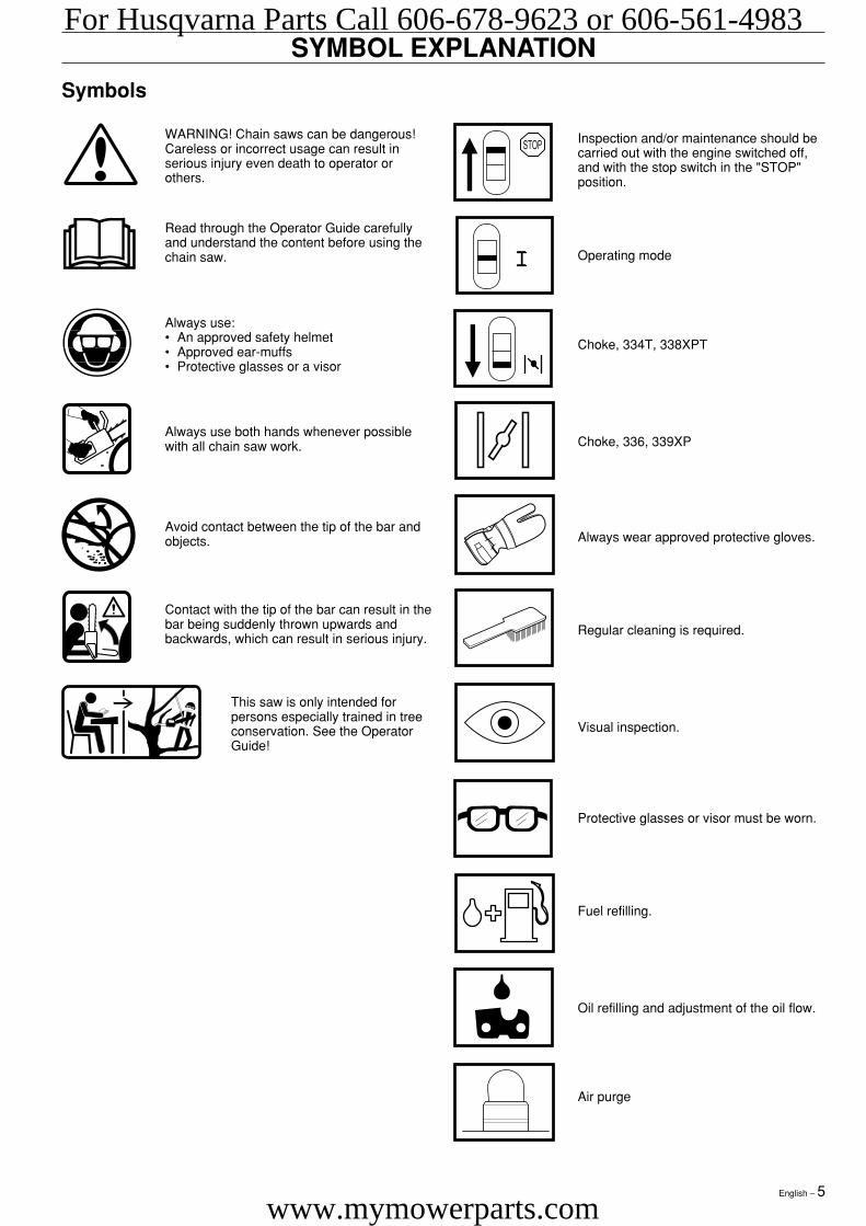
Symbols
Contact with the tip of the bar can result in thebar being suddenly thrown upwards andbackwards, which can result in serious injury.
This saw is only intended forpersons especially trained in treeconservation. See the OperatorGuide!
Oil refilling and adjustment of the oil flow.
WARNING! Chain saws can be dangerous!Careless or incorrect usage can result inserious injury even death to operator orothers.
Inspection and/or maintenance should becarried out with the engine switched off,and with the stop switch in the "STOP"position.
Read through the Operator Guide carefullyand understand the content before using thechain saw. Operating mode
Always use:• An approved safety helmet• Approved ear-muffs• Protective glasses or a visor
Choke, 334T, 338XPT
Choke, 336, 339XPAlways use both hands whenever possiblewith all chain saw work.
Always wear approved protective gloves.Avoid contact between the tip of the bar andobjects.
Regular cleaning is required.
Visual inspection.
Protective glasses or visor must be worn.
Fuel refilling.
Air purge
For Husqvarna Parts Call 606-678-9623 or 606-561-4983
www.mymowerparts.com
6 – English
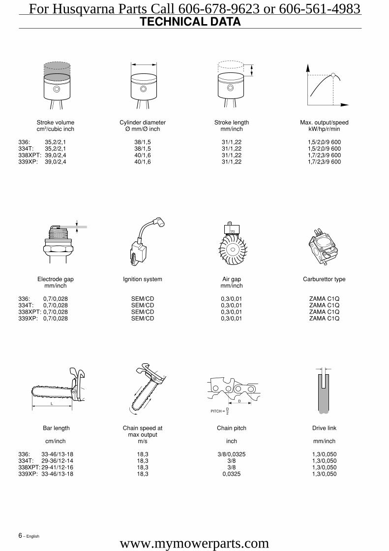
TECHNICAL DATA
Electrode gap Ignition system Air gap Carburettor typemm/inch mm/inch
336: 0,7/0,028 SEM/CD 0,3/0,01 ZAMA C1Q334T: 0,7/0,028 SEM/CD 0,3/0,01 ZAMA C1Q338XPT: 0,7/0,028 SEM/CD 0,3/0,01 ZAMA C1Q339XP: 0,7/0,028 SEM/CD 0,3/0,01 ZAMA C1Q
Bar length Chain speed at Chain pitch Drive linkmax output
cm/inch m/s inch mm/inch
336: 33-46/13-18 18,3 3/8/0,0325 1,3/0,050334T: 29-36/12-14 18,3 3/8 1,3/0,050338XPT: 29-41/12-16 18,3 3/8 1,3/0,050339XP: 33-46/13-18 18,3 0,0325 1,3/0,050
Stroke volume Cylinder diameter Stroke length Max. output/speedcm3/cubic inch Ø mm/Ø inch mm/inch kW/hp/r/min
336: 35,2/2,1 38/1,5 31/1,22 1,5/2,0/9 600334T: 35,2/2,1 38/1,5 31/1,22 1,5/2,0/9 600338XPT: 39,0/2,4 40/1,6 31/1,22 1,7/2,3/9 600339XP: 39,0/2,4 40/1,6 31/1,22 1,7/2,3/9 600
For Husqvarna Parts Call 606-678-9623 or 606-561-4983
www.mymowerparts.com
English – 7
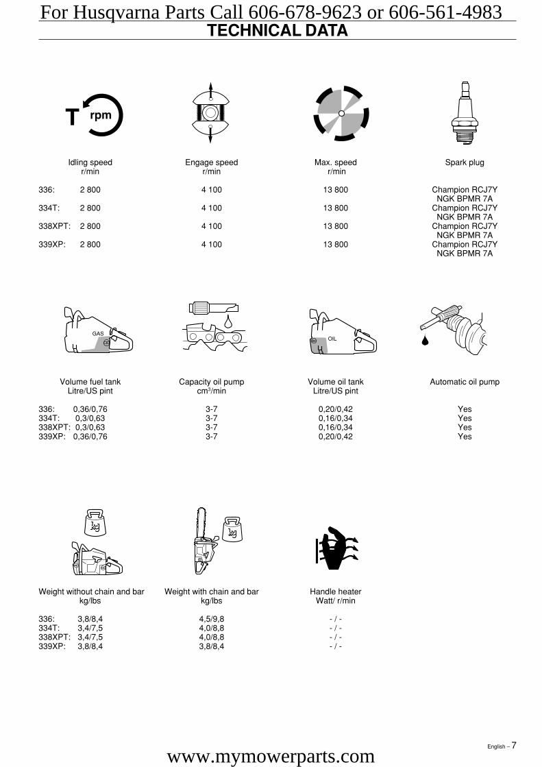
TECHNICAL DATA
Volume fuel tank Capacity oil pump Volume oil tank Automatic oil pumpLitre/US pint cm3/min Litre/US pint
336: 0,36/0,76 3-7 0,20/0,42 Yes334T: 0,3/0,63 3-7 0,16/0,34 Yes338XPT: 0,3/0,63 3-7 0,16/0,34 Yes339XP: 0,36/0,76 3-7 0,20/0,42 Yes
Weight without chain and bar Weight with chain and bar Handle heaterkg/lbs kg/lbs Watt/ r/min
336: 3,8/8,4 4,5/9,8 - / -334T: 3,4/7,5 4,0/8,8 - / -338XPT: 3,4/7,5 4,0/8,8 - / -339XP: 3,8/8,4 3,8/8,4 - / -
Idling speed Engage speed Max. speed Spark plugr/min r/min r/min
336: 2 800 4 100 13 800 Champion RCJ7YNGK BPMR 7A
334T: 2 800 4 100 13 800 Champion RCJ7YNGK BPMR 7A
338XPT: 2 800 4 100 13 800 Champion RCJ7YNGK BPMR 7A
339XP: 2 800 4 100 13 800 Champion RCJ7YNGK BPMR 7A
For Husqvarna Parts Call 606-678-9623 or 606-561-4983
www.mymowerparts.com
8 – English
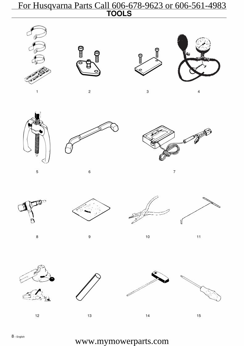
TOOLS
1 2 3 4
5 6 7
8 9 10 11
12 13 14 15
For Husqvarna Parts Call 606-678-9623 or 606-561-4983
www.mymowerparts.com
English – 9
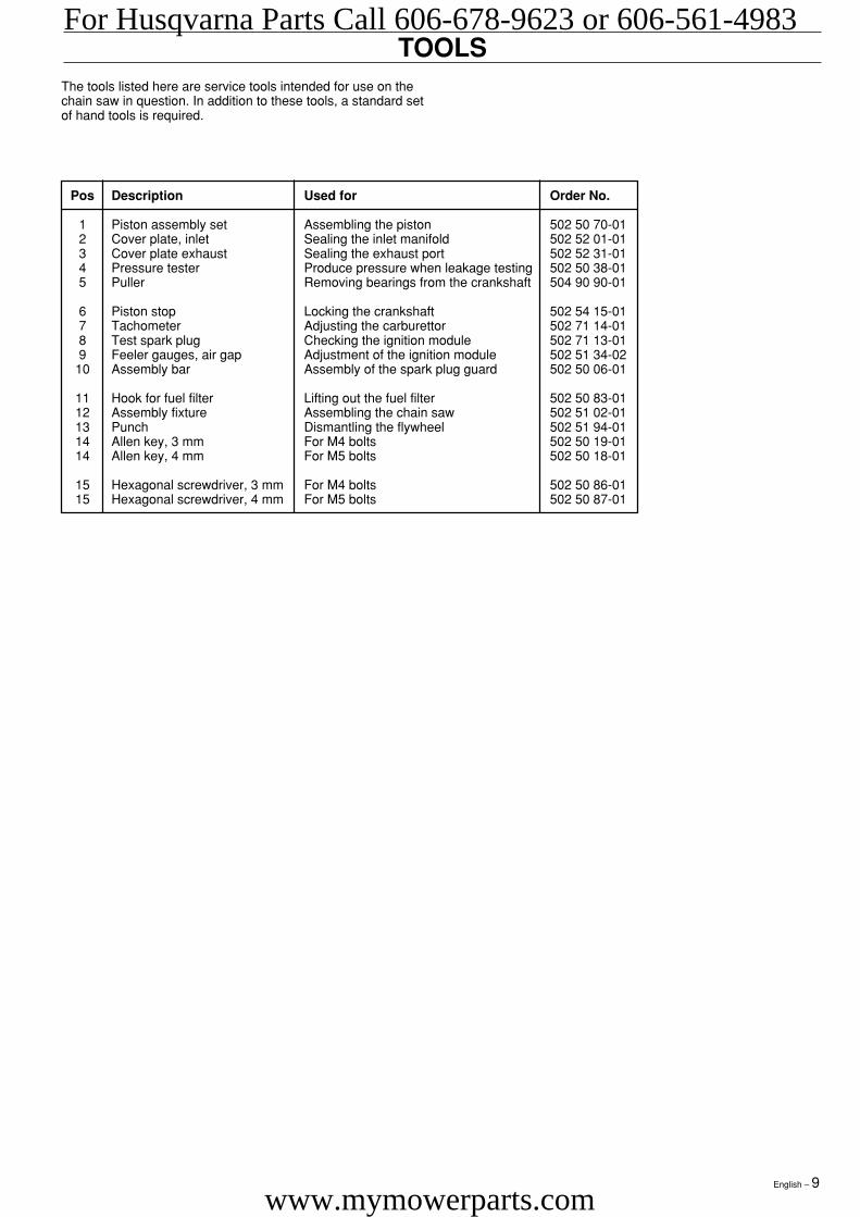
TOOLS
Pos Description Used for Order No.
1 Piston assembly set Assembling the piston 502 50 70-012 Cover plate, inlet Sealing the inlet manifold 502 52 01-013 Cover plate exhaust Sealing the exhaust port 502 52 31-014 Pressure tester Produce pressure when leakage testing 502 50 38-015 Puller Removing bearings from the crankshaft 504 90 90-01
6 Piston stop Locking the crankshaft 502 54 15-017 Tachometer Adjusting the carburettor 502 71 14-018 Test spark plug Checking the ignition module 502 71 13-019 Feeler gauges, air gap Adjustment of the ignition module 502 51 34-02
10 Assembly bar Assembly of the spark plug guard 502 50 06-01
11 Hook for fuel filter Lifting out the fuel filter 502 50 83-0112 Assembly fixture Assembling the chain saw 502 51 02-0113 Punch Dismantling the flywheel 502 51 94-0114 Allen key, 3 mm For M4 bolts 502 50 19-0114 Allen key, 4 mm For M5 bolts 502 50 18-01
15 Hexagonal screwdriver, 3 mm For M4 bolts 502 50 86-0115 Hexagonal screwdriver, 4 mm For M5 bolts 502 50 87-01
The tools listed here are service tools intended for use on thechain saw in question. In addition to these tools, a standard setof hand tools is required.
For Husqvarna Parts Call 606-678-9623 or 606-561-4983
www.mymowerparts.com

10 – English
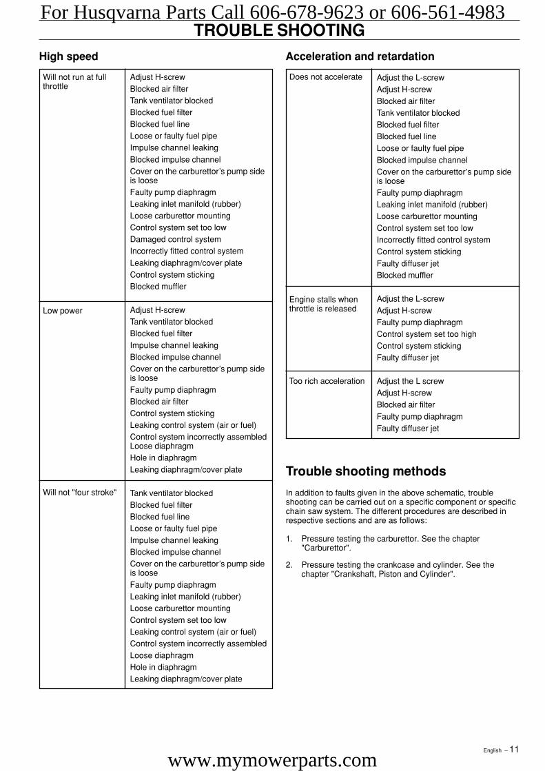
TROUBLE SHOOTING
Starting
Idling (low speed)
Adjust the L-screwLeaking inlet manifold (rubber)Loose carburettor mountingLoose or faulty fuel pipeBlocked fuel filterBlocked fuel lineTank ventilator blockedThrottle valve axle stiffThrottle sticksDefective throttle return springBent valve axle stopFaulty diffuser jet
Adjust the L screwWorn needle/needle tipControl system set too highWorn lever arm in the control systemLeaking diaphragm/cover plateControl system sticking
Does not idle
Too rich idling
Adjust the L-screwAir filter blockedChoke does not workWorn choke axleWorn choke valveBlocked fuel filterBlocked fuel linePiston ring seizedBlocked impulse channel
Loose or faulty fuel pipeHole in diaphragmWorn needle/needle tipControl system stickingControl system set too highLeaking control system (air or fuel)Cover on the carburettor’s pump sideis loose
Worn needle/needle tipControl system set too highControl system sticking
Difficult to start
Carburettor leaksfuel
Idling (low speed) (continued)
Idling with closed Lscrew
Worn needle/needle tipLeaking diaphragm/cover plateControl system stickingWorn lever arm in the control systemFaulty diffuser jet
Blocked fuel filterBlocked fuel lineLeaking inlet manifold (rubber)Loose carburettor mountingWorn throttle valve axleLoose throttle valve screwWorn throttle valveControl system stickingLeaking control system (air or fuel)Control system’s centre knob is wornHole in diaphragmLeaking diaphragm/cover plateLeaking crankcase
Blocked fuel lineControl system set too highControl system stickingLeaking control system (air or fuel)Leaking diaphragm/cover plateFaulty diffuser jetLeaking crankcase
Control system set too highControl system stickingDamaged control systemWorn needle/needle tipLeaking diaphragm/cover plateIncorrectly fitted control system
Trouble shooting chart
The different faults that can occur on the chain saw are dividedinto four groups as follows. Within each group possibleoperating faults are listed to the left while the probable faultalternatives are listed to the right. The most likely fault is listedfirst, etc.
Too much fuel whileidling
L-screw needsconstant adjustment
Uneven idling
Floods when theengine is not running
For Husqvarna Parts Call 606-678-9623 or 606-561-4983
www.mymowerparts.com
English – 11
Trouble shooting methods
In addition to faults given in the above schematic, troubleshooting can be carried out on a specific component or specificchain saw system. The different procedures are described inrespective sections and are as follows:
1. Pressure testing the carburettor. See the chapter"Carburettor".
2. Pressure testing the crankcase and cylinder. See thechapter "Crankshaft, Piston and Cylinder".
TROUBLE SHOOTINGHigh speed
Will not run at fullthrottle
Adjust H-screwBlocked air filterTank ventilator blockedBlocked fuel filterBlocked fuel lineLoose or faulty fuel pipeImpulse channel leakingBlocked impulse channelCover on the carburettor’s pump sideis looseFaulty pump diaphragmLeaking inlet manifold (rubber)Loose carburettor mountingControl system set too lowDamaged control systemIncorrectly fitted control systemLeaking diaphragm/cover plateControl system stickingBlocked muffler
Adjust H-screwTank ventilator blockedBlocked fuel filterImpulse channel leakingBlocked impulse channelCover on the carburettor’s pump sideis looseFaulty pump diaphragmBlocked air filterControl system stickingLeaking control system (air or fuel)Control system incorrectly assembledLoose diaphragmHole in diaphragmLeaking diaphragm/cover plate
Tank ventilator blockedBlocked fuel filterBlocked fuel lineLoose or faulty fuel pipeImpulse channel leakingBlocked impulse channelCover on the carburettor’s pump sideis looseFaulty pump diaphragmLeaking inlet manifold (rubber)Loose carburettor mountingControl system set too lowLeaking control system (air or fuel)Control system incorrectly assembledLoose diaphragmHole in diaphragmLeaking diaphragm/cover plate
Adjust the L-screwAdjust H-screwBlocked air filterTank ventilator blockedBlocked fuel filterBlocked fuel lineLoose or faulty fuel pipeBlocked impulse channelCover on the carburettor’s pump sideis looseFaulty pump diaphragmLeaking inlet manifold (rubber)Loose carburettor mountingControl system set too lowIncorrectly fitted control systemControl system stickingFaulty diffuser jetBlocked muffler
Adjust the L-screwAdjust H-screwFaulty pump diaphragmControl system set too highControl system stickingFaulty diffuser jet
Adjust the L screwAdjust H-screwBlocked air filterFaulty pump diaphragmFaulty diffuser jet
Does not accelerate
Acceleration and retardation
Will not "four stroke"
Low power
Too rich acceleration
Engine stalls whenthrottle is released
For Husqvarna Parts Call 606-678-9623 or 606-561-4983
www.mymowerparts.com
12 – English
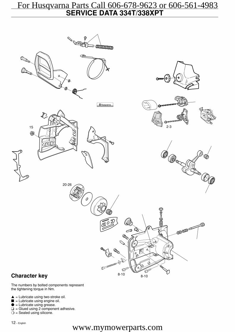
SERVICE DATA 334T/338XPT
Character key
The numbers by bolted components representthe tightening torque in Nm.
▲ = Lubricate using two-stroke oil.■ = Lubricate using engine oil.● = Lubricate using grease.❑ = Glued using 2 component adhesive.❍ = Sealed using silicone.
2-315
8-10 8-10
20-26
For Husqvarna Parts Call 606-678-9623 or 606-561-4983
www.mymowerparts.com
English – 13
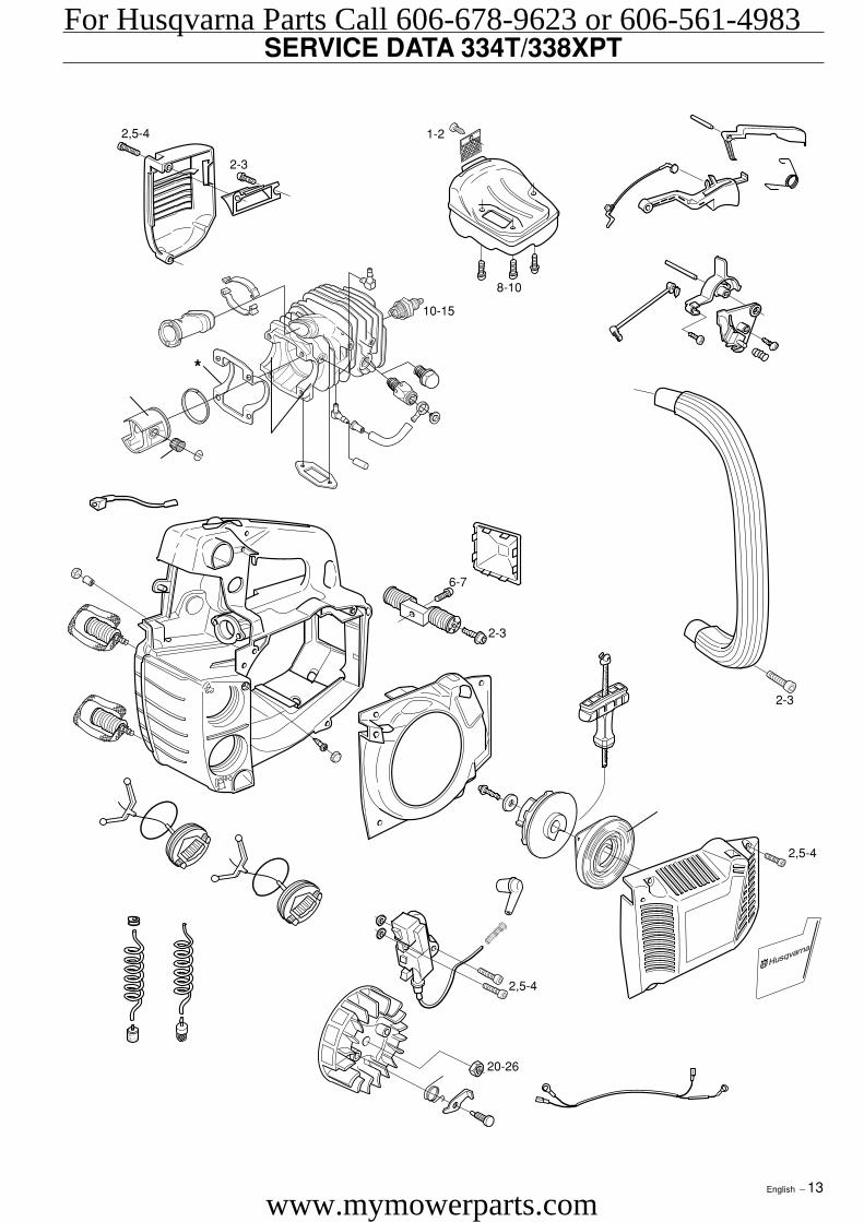
SERVICE DATA 334T/338XPT
2,5-4
1-22,5-4
2-3
8-10
10-15
2-3
2,5-4
20-26
2-3
6-7
*
For Husqvarna Parts Call 606-678-9623 or 606-561-4983
www.mymowerparts.com
14 – English
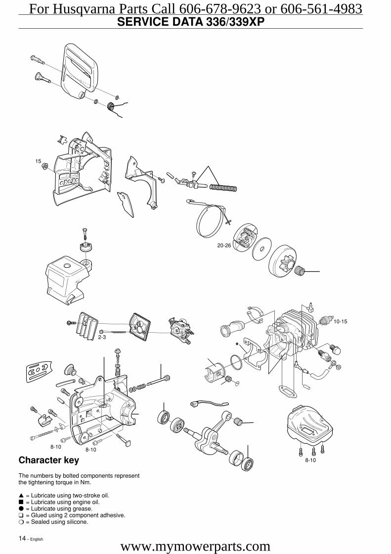
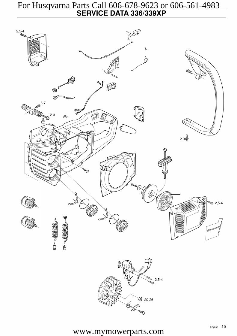
SERVICE DATA 336/339XP
Character key
The numbers by bolted components representthe tightening torque in Nm.
▲ = Lubricate using two-stroke oil.■ = Lubricate using engine oil.● = Lubricate using grease.❑ = Glued using 2 component adhesive.❍ = Sealed using silicone.
2-3
15
8-10 8-10
20-26
8-10
10-15
*
For Husqvarna Parts Call 606-678-9623 or 606-561-4983
www.mymowerparts.com
English – 15
SERVICE DATA 336/339XP
ST
OP
2,5-4
2,5-4
2-3
2,5-4
20-26
2-3
6-7
For Husqvarna Parts Call 606-678-9623 or 606-561-4983
www.mymowerparts.com
16 – English
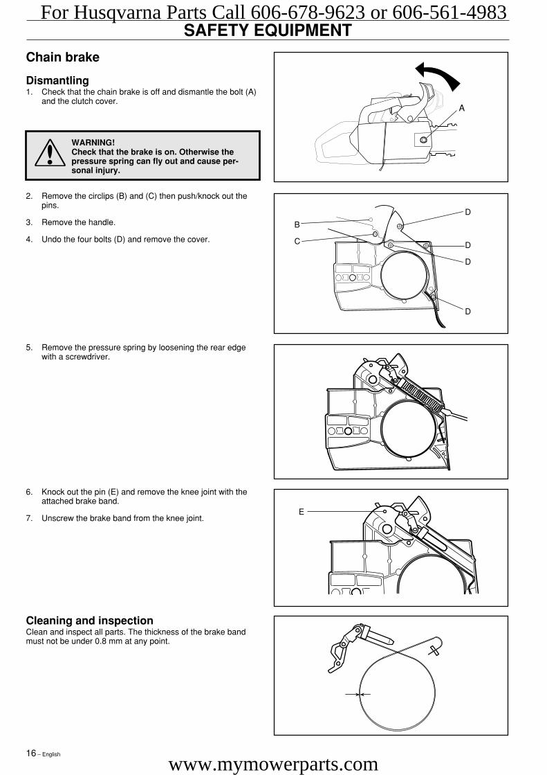
SAFETY EQUIPMENT
Cleaning and inspectionClean and inspect all parts. The thickness of the brake bandmust not be under 0.8 mm at any point.
2. Remove the circlips (B) and (C) then push/knock out thepins.
3. Remove the handle.
4. Undo the four bolts (D) and remove the cover.
Chain brake
Dismantling1. Check that the chain brake is off and dismantle the bolt (A)
and the clutch cover.
6. Knock out the pin (E) and remove the knee joint with theattached brake band.
7. Unscrew the brake band from the knee joint.
WARNING!Check that the brake is on. Otherwise thepressure spring can fly out and cause per-sonal injury.
5. Remove the pressure spring by loosening the rear edgewith a screwdriver.
D
D
D
D
B
C
E
A
For Husqvarna Parts Call 606-678-9623 or 606-561-4983
www.mymowerparts.com
English – 17
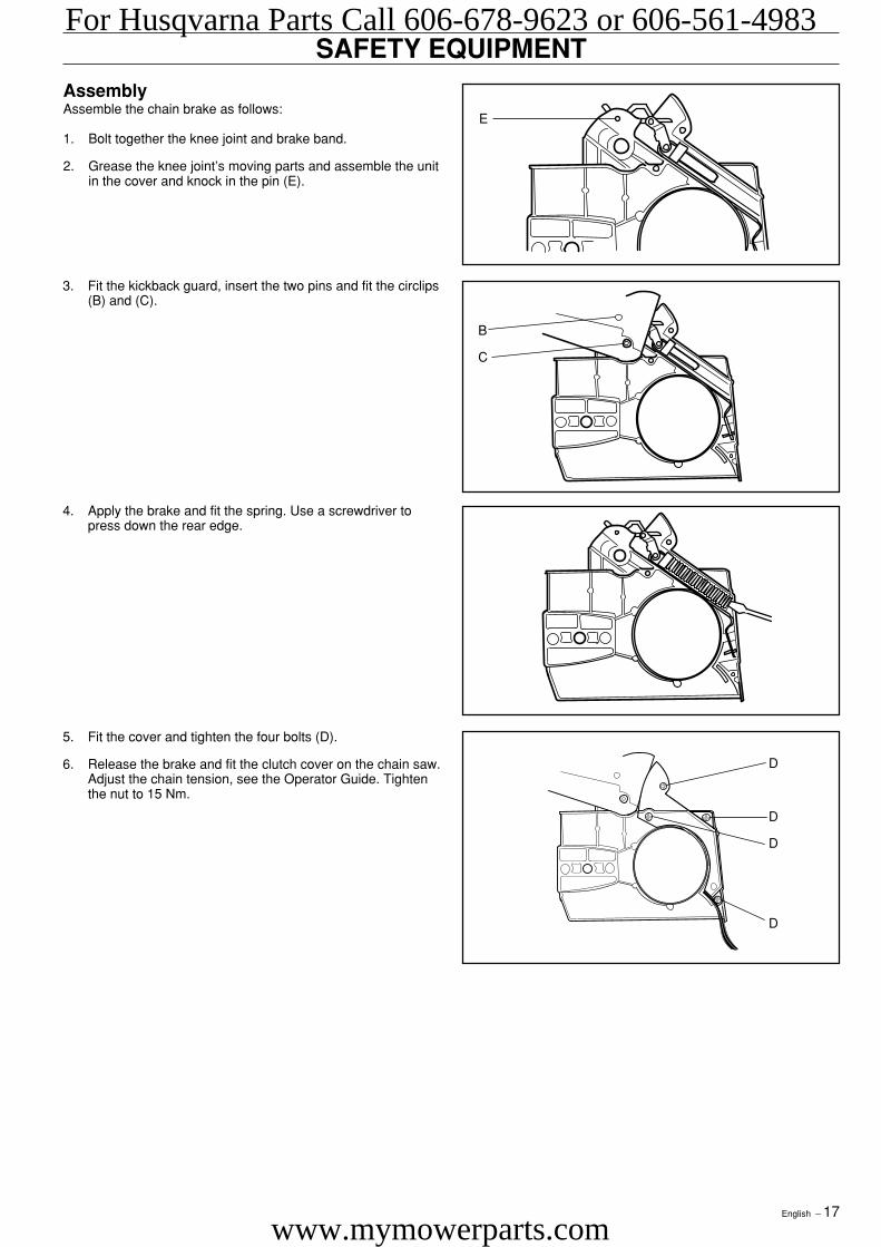
SAFETY EQUIPMENTAssemblyAssemble the chain brake as follows:
1. Bolt together the knee joint and brake band.
2. Grease the knee joint’s moving parts and assemble the unitin the cover and knock in the pin (E).
B
C
E
D
D
D
D
5. Fit the cover and tighten the four bolts (D).
6. Release the brake and fit the clutch cover on the chain saw.Adjust the chain tension, see the Operator Guide. Tightenthe nut to 15 Nm.
4. Apply the brake and fit the spring. Use a screwdriver topress down the rear edge.
3. Fit the kickback guard, insert the two pins and fit the circlips(B) and (C).
For Husqvarna Parts Call 606-678-9623 or 606-561-4983
www.mymowerparts.com
18 – English
SAFETY EQUIPMENT
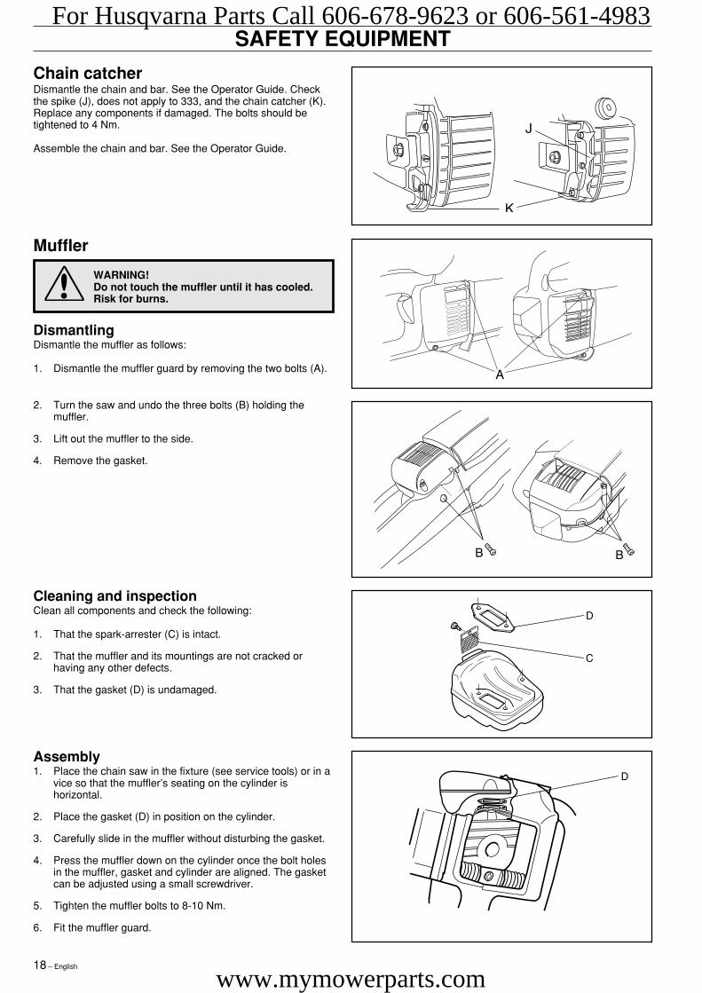
Chain catcherDismantle the chain and bar. See the Operator Guide. Checkthe spike (J), does not apply to 333, and the chain catcher (K).Replace any components if damaged. The bolts should betightened to 4 Nm.
Assemble the chain and bar. See the Operator Guide.
Cleaning and inspectionClean all components and check the following:
1. That the spark-arrester (C) is intact.
2. That the muffler and its mountings are not cracked orhaving any other defects.
3. That the gasket (D) is undamaged.
Assembly1. Place the chain saw in the fixture (see service tools) or in a
vice so that the muffler’s seating on the cylinder ishorizontal.
2. Place the gasket (D) in position on the cylinder.
3. Carefully slide in the muffler without disturbing the gasket.
4. Press the muffler down on the cylinder once the bolt holesin the muffler, gasket and cylinder are aligned. The gasketcan be adjusted using a small screwdriver.
5. Tighten the muffler bolts to 8-10 Nm.
6. Fit the muffler guard.
DismantlingDismantle the muffler as follows:
1. Dismantle the muffler guard by removing the two bolts (A).
Muffler
2. Turn the saw and undo the three bolts (B) holding themuffler.
3. Lift out the muffler to the side.
4. Remove the gasket.
WARNING!Do not touch the muffler until it has cooled.Risk for burns.
D
C
D
For Husqvarna Parts Call 606-678-9623 or 606-561-4983
www.mymowerparts.com
English – 19
SAFETY EQUIPMENT
Throttle lock and stop function
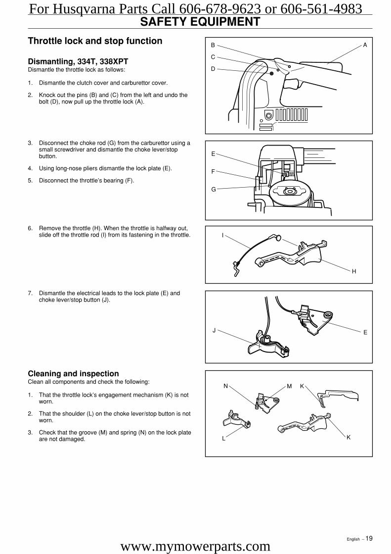
Dismantling, 334T, 338XPTDismantle the throttle lock as follows:
1. Dismantle the clutch cover and carburettor cover.
2. Knock out the pins (B) and (C) from the left and undo thebolt (D), now pull up the throttle lock (A).
Cleaning and inspectionClean all components and check the following:
1. That the throttle lock’s engagement mechanism (K) is notworn.
2. That the shoulder (L) on the choke lever/stop button is notworn.
3. Check that the groove (M) and spring (N) on the lock plateare not damaged.
I
H
J E
M K
L K
N
B
C
D
A
E
F
G
7. Dismantle the electrical leads to the lock plate (E) andchoke lever/stop button (J).
3. Disconnect the choke rod (G) from the carburettor using asmall screwdriver and dismantle the choke lever/stopbutton.
4. Using long-nose pliers dismantle the lock plate (E).
5. Disconnect the throttle’s bearing (F).
6. Remove the throttle (H). When the throttle is halfway out,slide off the throttle rod (I) from its fastening in the throttle.
For Husqvarna Parts Call 606-678-9623 or 606-561-4983
www.mymowerparts.com
20 – English
SAFETY EQUIPMENTAssembly 334T, 338XPTAssemble the components as follows:
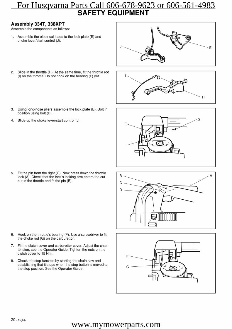
1. Assemble the electrical leads to the lock plate (E) andchoke lever/start control (J).
I
H
J E
F
G
DE
F
B
C
D
A
6. Hook on the throttle’s bearing (F). Use a screwdriver to fitthe choke rod (G) on the carburettor.
7. Fit the clutch cover and carburettor cover. Adjust the chaintension, see the Operator Guide. Tighten the nuts on theclutch cover to 15 Nm.
8. Check the stop function by starting the chain saw andestablishing that it stops when the stop button is moved tothe stop position. See the Operator Guide.
5. Fit the pin from the right (C). Now press down the throttlelock (A). Check that the lock’s locking arm enters the cut-out in the throttle and fit the pin (B).
3. Using long-nose pliers assemble the lock plate (E). Bolt inposition using bolt (D).
4. Slide up the choke lever/start control (J).
2. Slide in the throttle (H). At the same time, fit the throttle rod(I) on the throttle. Do not hook on the bearing (F) yet.
For Husqvarna Parts Call 606-678-9623 or 606-561-4983
www.mymowerparts.com
English – 21
SAFETY EQUIPMENTDismantling 336, 339XP
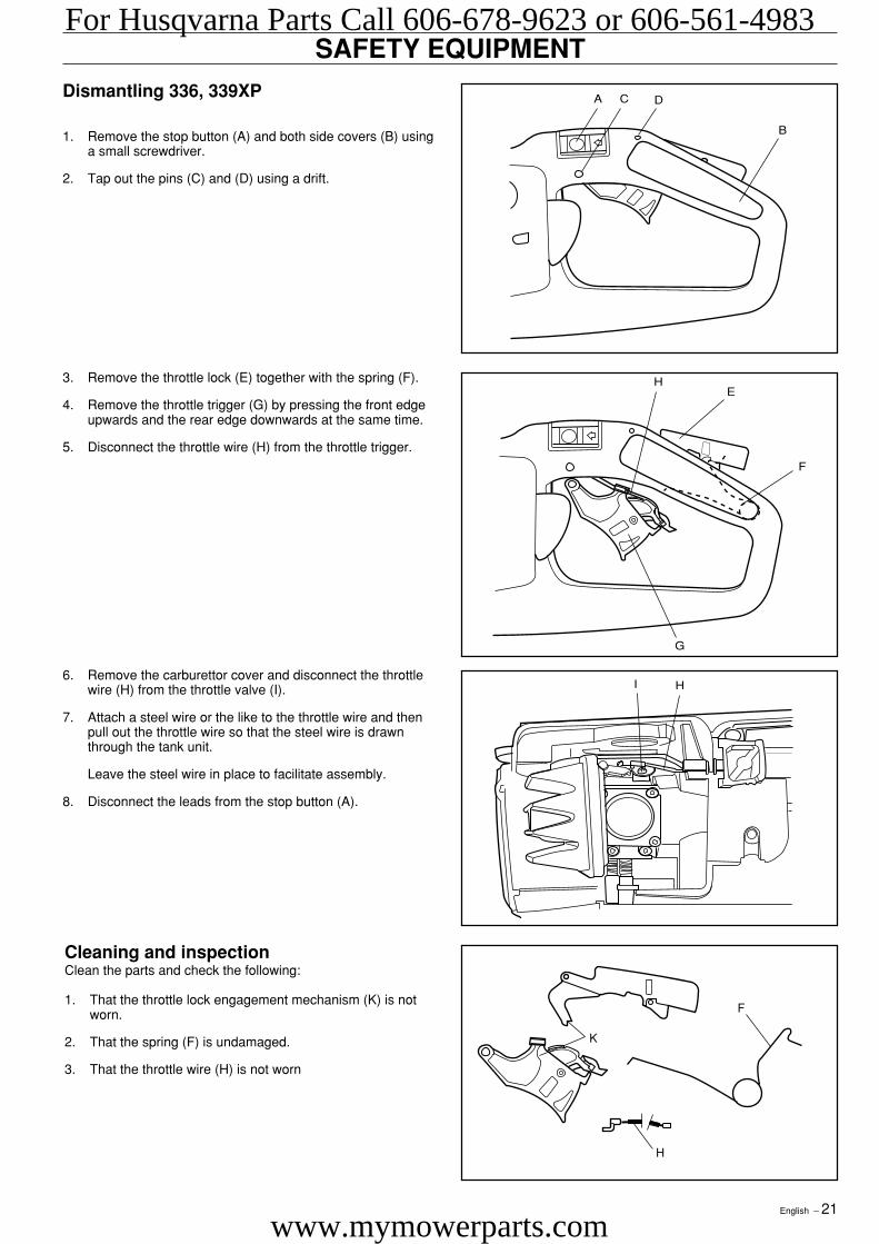
1. Remove the stop button (A) and both side covers (B) usinga small screwdriver.
2. Tap out the pins (C) and (D) using a drift.
Cleaning and inspectionClean the parts and check the following:
1. That the throttle lock engagement mechanism (K) is notworn.
2. That the spring (F) is undamaged.
3. That the throttle wire (H) is not worn
3. Remove the throttle lock (E) together with the spring (F).
4. Remove the throttle trigger (G) by pressing the front edgeupwards and the rear edge downwards at the same time.
5. Disconnect the throttle wire (H) from the throttle trigger.
6. Remove the carburettor cover and disconnect the throttlewire (H) from the throttle valve (I).
7. Attach a steel wire or the like to the throttle wire and thenpull out the throttle wire so that the steel wire is drawnthrough the tank unit.
Leave the steel wire in place to facilitate assembly.
8. Disconnect the leads from the stop button (A).
A C D
B
HE
F
G
I H
K
H
F
For Husqvarna Parts Call 606-678-9623 or 606-561-4983
www.mymowerparts.com
22 – English
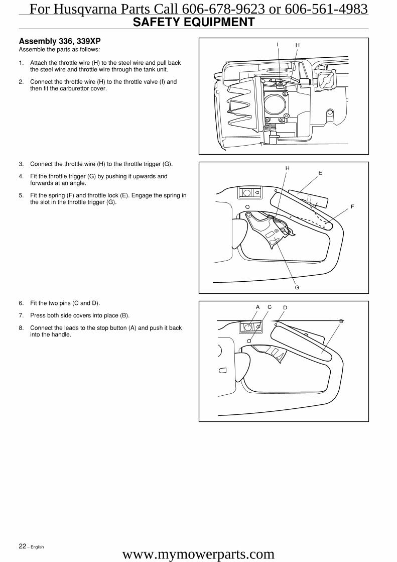
SAFETY EQUIPMENTAssembly 336, 339XPAssemble the parts as follows:
1. Attach the throttle wire (H) to the steel wire and pull backthe steel wire and throttle wire through the tank unit.
2. Connect the throttle wire (H) to the throttle valve (I) andthen fit the carburettor cover.
6. Fit the two pins (C and D).
7. Press both side covers into place (B).
8. Connect the leads to the stop button (A) and push it backinto the handle.
3. Connect the throttle wire (H) to the throttle trigger (G).
4. Fit the throttle trigger (G) by pushing it upwards andforwards at an angle.
5. Fit the spring (F) and throttle lock (E). Engage the spring inthe slot in the throttle trigger (G).
I H
HE
F
G
A C D
B
For Husqvarna Parts Call 606-678-9623 or 606-561-4983
www.mymowerparts.com
English – 23
STARTER
WARNING!
• The return spring is under tension when in its cassettein the starter and can, with careless handing, fly outand cause personal injury.
• Care must be exercised when replacing the recoilspring or the starter cord. Wear protective glasses.
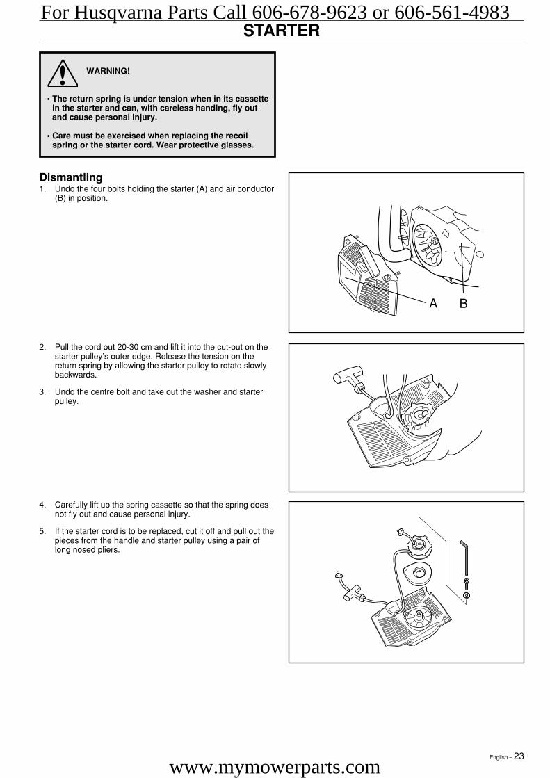
Dismantling1. Undo the four bolts holding the starter (A) and air conductor
(B) in position.
4. Carefully lift up the spring cassette so that the spring doesnot fly out and cause personal injury.
5. If the starter cord is to be replaced, cut it off and pull out thepieces from the handle and starter pulley using a pair oflong nosed pliers.
2. Pull the cord out 20-30 cm and lift it into the cut-out on thestarter pulley’s outer edge. Release the tension on thereturn spring by allowing the starter pulley to rotate slowlybackwards.
3. Undo the centre bolt and take out the washer and starterpulley.
A B
For Husqvarna Parts Call 606-678-9623 or 606-561-4983
www.mymowerparts.com
24 – English
STARTERCleaning and inspectionClean all components and check the following:
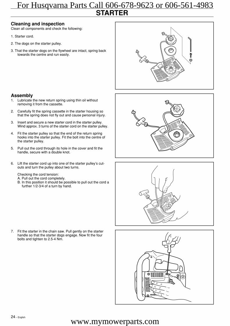
1. Starter cord.
2. The dogs on the starter pulley.
3. That the starter dogs on the flywheel are intact, spring backtowards the centre and run easily.
Assembly1. Lubricate the new return spring using thin oil without
removing it from the cassette.
2. Carefully fit the spring cassette in the starter housing sothat the spring does not fly out and cause personal injury.
3. Insert and secure a new starter cord in the starter pulley.Wind approx. 3 turns of the starter cord on the starter pulley.
4. Fit the starter pulley so that the end of the return springhooks into the starter pulley. Fit the bolt into the centre ofthe starter pulley.
5. Pull out the cord through its hole in the cover and fit thehandle, secure with a double knot.
7. Fit the starter in the chain saw. Pull gently on the starterhandle so that the starter dogs engage. Now fit the fourbolts and tighten to 2.5-4 Nm.
6. Lift the starter cord up into one of the starter pulley’s cut-outs and turn the pulley about two turns.
Checking the cord tension:A. Pull out the cord completely.B. In this position it should be possible to pull out the cord a
further 1/2-3/4 of a turn by hand.
For Husqvarna Parts Call 606-678-9623 or 606-561-4983
www.mymowerparts.com
English – 25
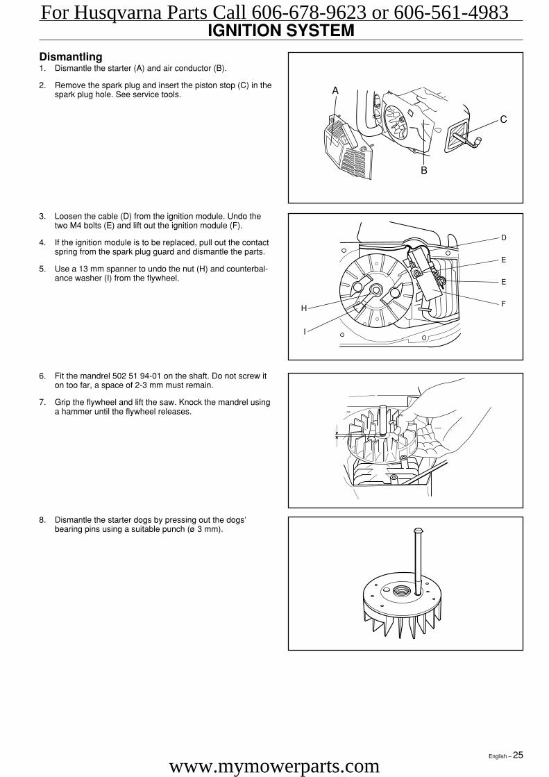
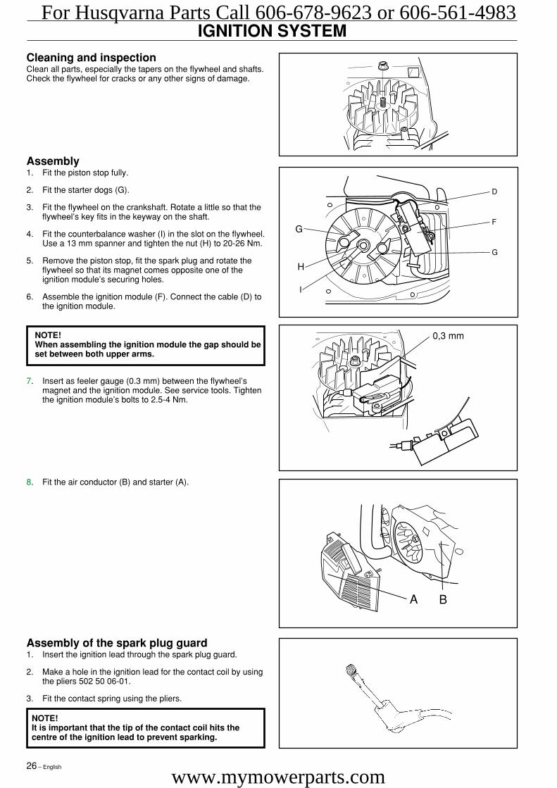
IGNITION SYSTEMDismantling1. Dismantle the starter (A) and air conductor (B).
2. Remove the spark plug and insert the piston stop (C) in thespark plug hole. See service tools.
D
E
E
FH
I
8. Dismantle the starter dogs by pressing out the dogs’bearing pins using a suitable punch (ø 3 mm).
6. Fit the mandrel 502 51 94-01 on the shaft. Do not screw iton too far, a space of 2-3 mm must remain.
7. Grip the flywheel and lift the saw. Knock the mandrel usinga hammer until the flywheel releases.
3. Loosen the cable (D) from the ignition module. Undo thetwo M4 bolts (E) and lift out the ignition module (F).
4. If the ignition module is to be replaced, pull out the contactspring from the spark plug guard and dismantle the parts.
5. Use a 13 mm spanner to undo the nut (H) and counterbal-ance washer (I) from the flywheel.
A
B
C
For Husqvarna Parts Call 606-678-9623 or 606-561-4983
www.mymowerparts.com
26 – English
Cleaning and inspectionClean all parts, especially the tapers on the flywheel and shafts.Check the flywheel for cracks or any other signs of damage.
Assembly of the spark plug guard1. Insert the ignition lead through the spark plug guard.
2. Make a hole in the ignition lead for the contact coil by usingthe pliers 502 50 06-01.
3. Fit the contact spring using the pliers.
NOTE!It is important that the tip of the contact coil hits thecentre of the ignition lead to prevent sparking.
IGNITION SYSTEM
D
F
G
G
H
I
0,3 mm
8. Fit the air conductor (B) and starter (A).
Assembly1. Fit the piston stop fully.
2. Fit the starter dogs (G).
3. Fit the flywheel on the crankshaft. Rotate a little so that theflywheel’s key fits in the keyway on the shaft.
4. Fit the counterbalance washer (I) in the slot on the flywheel.Use a 13 mm spanner and tighten the nut (H) to 20-26 Nm.
5. Remove the piston stop, fit the spark plug and rotate theflywheel so that its magnet comes opposite one of theignition module’s securing holes.
6. Assemble the ignition module (F). Connect the cable (D) tothe ignition module.
7. Insert as feeler gauge (0.3 mm) between the flywheel’smagnet and the ignition module. See service tools. Tightenthe ignition module’s bolts to 2.5-4 Nm.
NOTE!When assembling the ignition module the gap should beset between both upper arms.
A B
For Husqvarna Parts Call 606-678-9623 or 606-561-4983
www.mymowerparts.com
English – 27
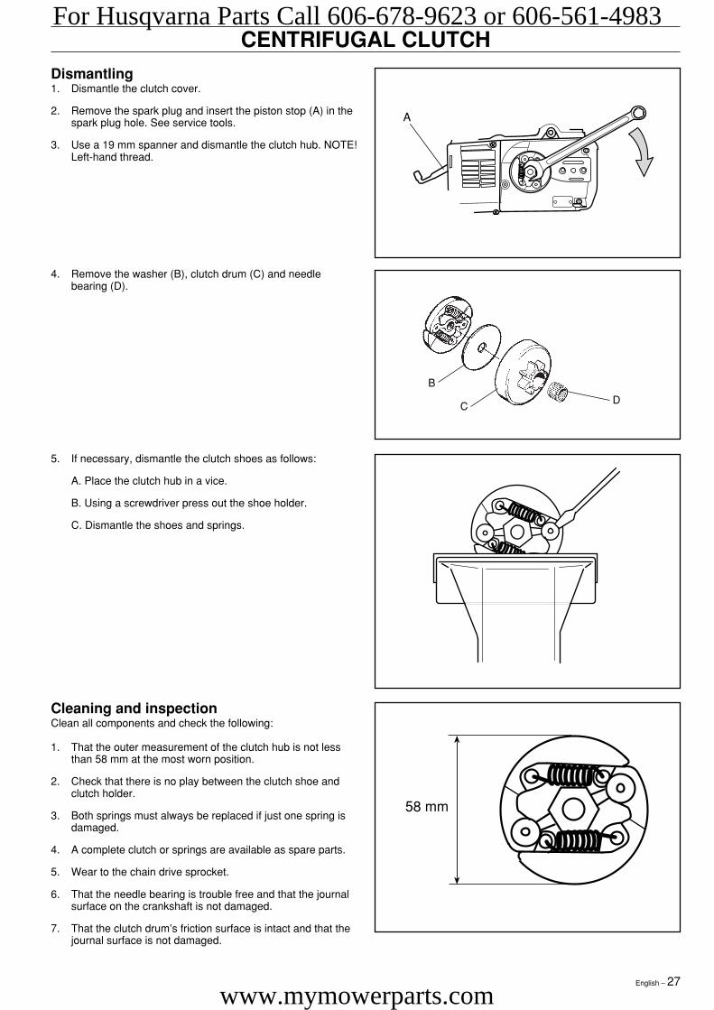
CENTRIFUGAL CLUTCHDismantling1. Dismantle the clutch cover.
2. Remove the spark plug and insert the piston stop (A) in thespark plug hole. See service tools.
3. Use a 19 mm spanner and dismantle the clutch hub. NOTE!Left-hand thread.
Cleaning and inspectionClean all components and check the following:
1. That the outer measurement of the clutch hub is not lessthan 58 mm at the most worn position.
2. Check that there is no play between the clutch shoe andclutch holder.
3. Both springs must always be replaced if just one spring isdamaged.
4. A complete clutch or springs are available as spare parts.
5. Wear to the chain drive sprocket.
6. That the needle bearing is trouble free and that the journalsurface on the crankshaft is not damaged.
7. That the clutch drum’s friction surface is intact and that thejournal surface is not damaged.
58 mm
5. If necessary, dismantle the clutch shoes as follows:
A. Place the clutch hub in a vice.
B. Using a screwdriver press out the shoe holder.
C. Dismantle the shoes and springs.
4. Remove the washer (B), clutch drum (C) and needlebearing (D).
B
CD
A
For Husqvarna Parts Call 606-678-9623 or 606-561-4983
www.mymowerparts.com
28 – English
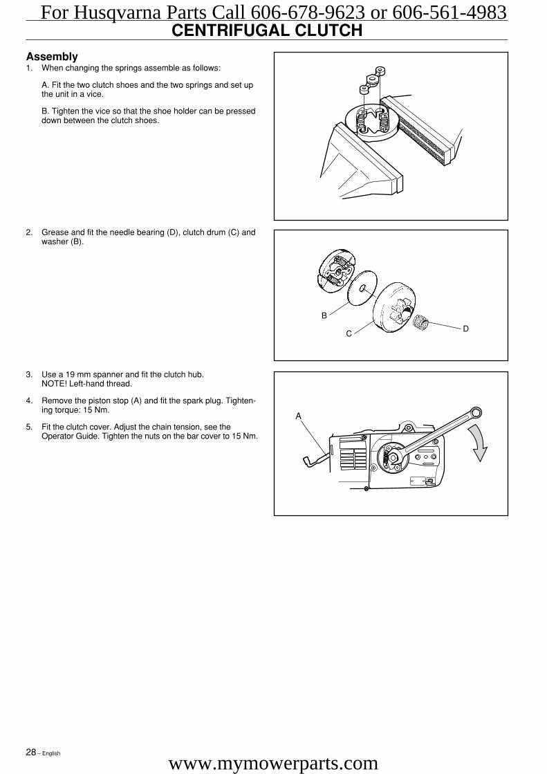
CENTRIFUGAL CLUTCHAssembly1. When changing the springs assemble as follows:
A. Fit the two clutch shoes and the two springs and set upthe unit in a vice.
B. Tighten the vice so that the shoe holder can be presseddown between the clutch shoes.
3. Use a 19 mm spanner and fit the clutch hub.NOTE! Left-hand thread.
4. Remove the piston stop (A) and fit the spark plug. Tighten-ing torque: 15 Nm.
5. Fit the clutch cover. Adjust the chain tension, see theOperator Guide. Tighten the nuts on the bar cover to 15 Nm.
2. Grease and fit the needle bearing (D), clutch drum (C) andwasher (B).
B
CD
A
For Husqvarna Parts Call 606-678-9623 or 606-561-4983
www.mymowerparts.com
English – 29
CARBURETTOR
Description
WARNING!The fuel used in the chain saw has the follow-ing hazardous properties:• The fluid and its vapour are poisonous.• Can cause skin irritation.• Is highly inflammable.
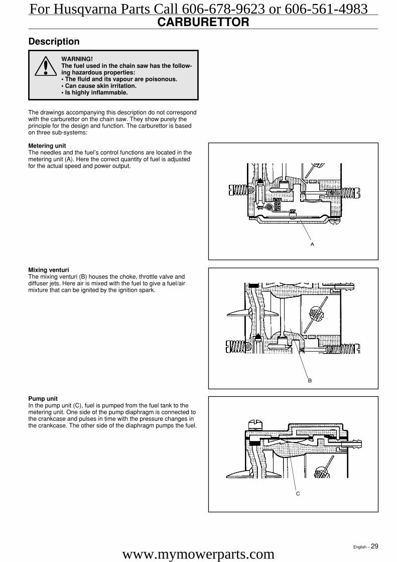
The drawings accompanying this description do not correspondwith the carburettor on the chain saw. They show purely theprinciple for the design and function. The carburettor is basedon three sub-systems:
Metering unitThe needles and the fuel’s control functions are located in themetering unit (A). Here the correct quantity of fuel is adjustedfor the actual speed and power output.
A
B
C
Pump unitIn the pump unit (C), fuel is pumped from the fuel tank to themetering unit. One side of the pump diaphragm is connected tothe crankcase and pulses in time with the pressure changes inthe crankcase. The other side of the diaphragm pumps the fuel.
Mixing venturiThe mixing venturi (B) houses the choke, throttle valve anddiffuser jets. Here air is mixed with the fuel to give a fuel/airmixture that can be ignited by the ignition spark.
For Husqvarna Parts Call 606-678-9623 or 606-561-4983
www.mymowerparts.com
30 – English
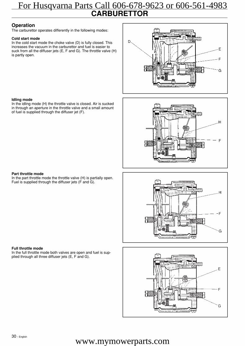
OperationThe carburettor operates differently in the following modes:
Cold start modeIn the cold start mode the choke valve (D) is fully closed. Thisincreases the vacuum in the carburettor and fuel is easier tosuck from all the diffuser jets (E, F and G). The throttle valve (H)is partly open.
Full throttle modeIn the full throttle mode both valves are open and fuel is sup-plied through all three diffuser jets (E, F and G).
Part throttle modeIn the part throttle mode the throttle valve (H) is partially open.Fuel is supplied through the diffuser jets (F and G).
Idling modeIn the idling mode (H) the throttle valve is closed. Air is suckedin through an aperture in the throttle valve and a small amountof fuel is supplied through the diffuser jet (F).
CARBURETTORFor Husqvarna Parts Call 606-678-9623 or 606-561-4983
www.mymowerparts.com
English – 31
CARBURETTOR
1.
2.
4.
3.
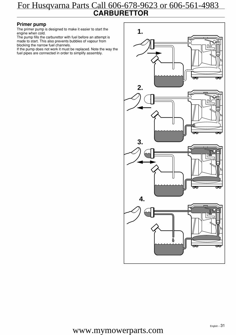
Primer pumpThe primer pump is designed to make it easier to start theengine when cold.The pump fills the carburettor with fuel before an attempt ismade to start. This also prevents bubbles of vapour fromblocking the narrow fuel channels.If the pump does not work it must be replaced. Note the way thefuel pipes are connected in order to simplify assembly.
For Husqvarna Parts Call 606-678-9623 or 606-561-4983
www.mymowerparts.com
32 – English
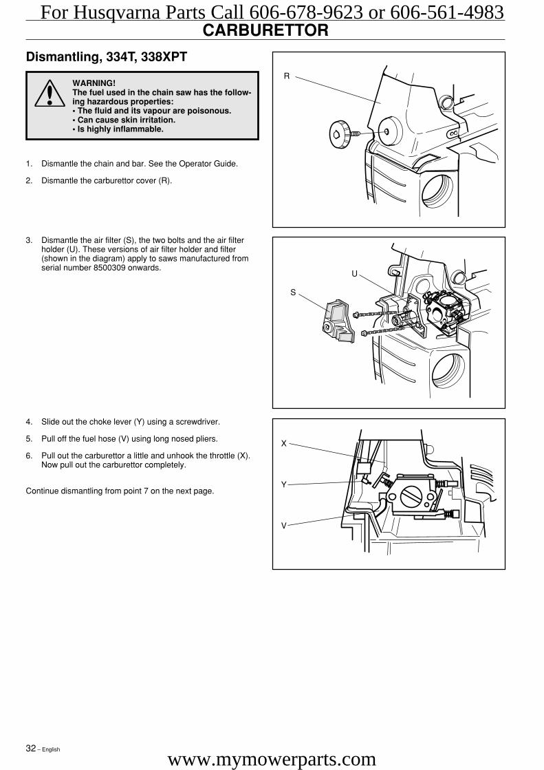
4. Slide out the choke lever (Y) using a screwdriver.
5. Pull off the fuel hose (V) using long nosed pliers.
6. Pull out the carburettor a little and unhook the throttle (X).Now pull out the carburettor completely.
Continue dismantling from point 7 on the next page.
3. Dismantle the air filter (S), the two bolts and the air filterholder (U). These versions of air filter holder and filter(shown in the diagram) apply to saws manufactured fromserial number 8500309 onwards.
1. Dismantle the chain and bar. See the Operator Guide.
2. Dismantle the carburettor cover (R).
CARBURETTOR
Dismantling, 334T, 338XPT
WARNING!The fuel used in the chain saw has the follow-ing hazardous properties:• The fluid and its vapour are poisonous.• Can cause skin irritation.• Is highly inflammable.
R
U
S
X
Y
V
For Husqvarna Parts Call 606-678-9623 or 606-561-4983
www.mymowerparts.com
English – 33
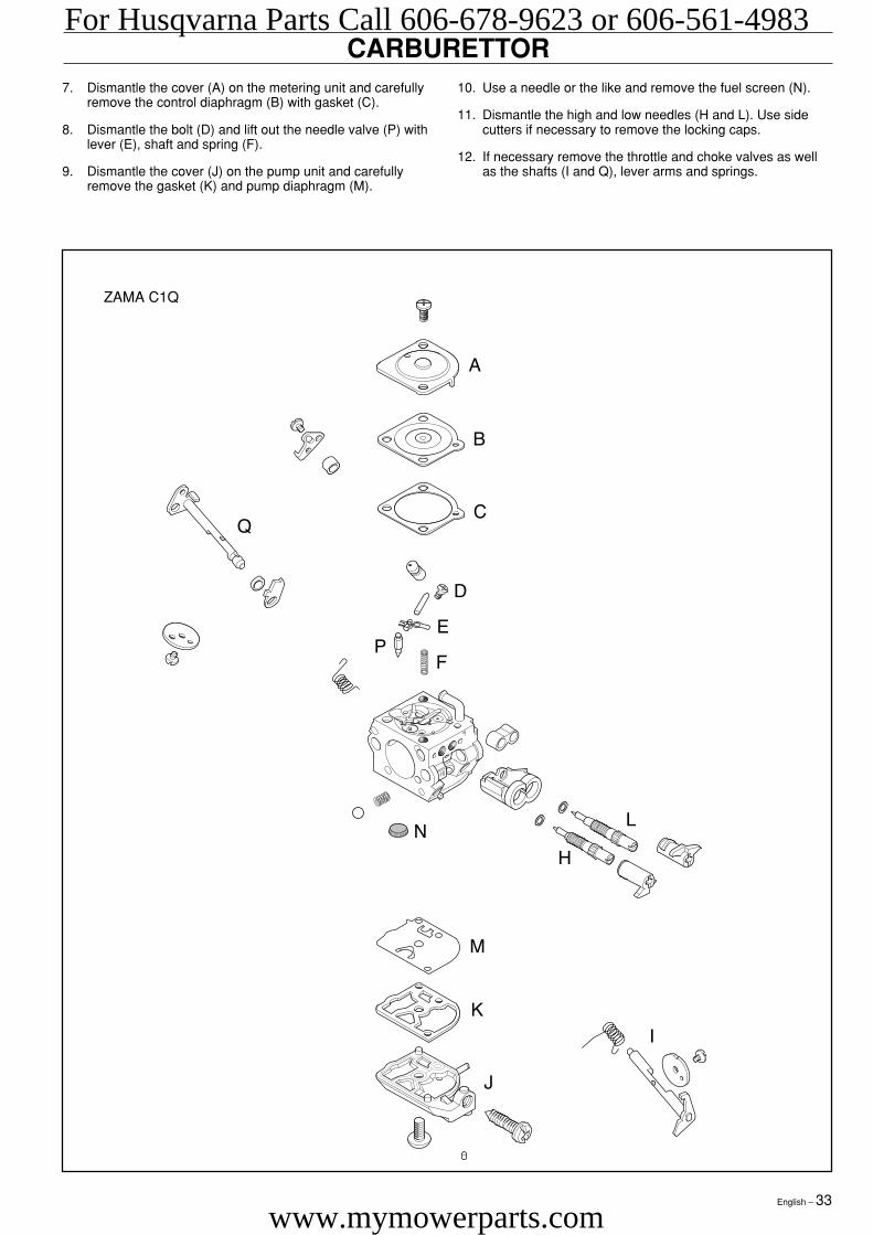
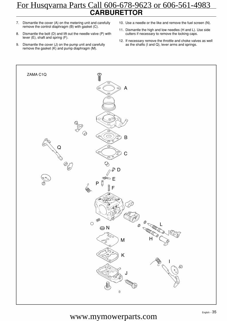
CARBURETTOR7. Dismantle the cover (A) on the metering unit and carefully
remove the control diaphragm (B) with gasket (C).
8. Dismantle the bolt (D) and lift out the needle valve (P) withlever (E), shaft and spring (F).
9. Dismantle the cover (J) on the pump unit and carefullyremove the gasket (K) and pump diaphragm (M).
10. Use a needle or the like and remove the fuel screen (N).
11. Dismantle the high and low needles (H and L). Use sidecutters if necessary to remove the locking caps.
12. If necessary remove the throttle and choke valves as wellas the shafts (I and Q), lever arms and springs.
ZAMA C1Q
For Husqvarna Parts Call 606-678-9623 or 606-561-4983
www.mymowerparts.com
34 – English
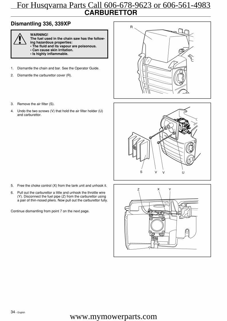
5. Free the choke control (X) from the tank unit and unhook it.
6. Pull out the carburettor a little and unhook the throttle wire(Y). Disconnect the fuel pipe (Z) from the carburettor usinga pair of thin-nosed pliers. Now pull out the carburettor fully.
Continue dismantling from point 7 on the next page.
3. Remove the air filter (S).
4. Undo the two screws (V) that hold the air filter holder (U)and carburettor.
1. Dismantle the chain and bar. See the Operator Guide.
2. Dismantle the carburettor cover (R).
CARBURETTOR
Dismantling 336, 339XP
WARNING!The fuel used in the chain saw has the follow-ing hazardous properties:• The fluid and its vapour are poisonous.• Can cause skin irritation.• Is highly inflammable.
Z X Y
R
S V V U
For Husqvarna Parts Call 606-678-9623 or 606-561-4983
www.mymowerparts.com
English – 35
CARBURETTOR7. Dismantle the cover (A) on the metering unit and carefully
remove the control diaphragm (B) with gasket (C).
8. Dismantle the bolt (D) and lift out the needle valve (P) withlever (E), shaft and spring (F).
9. Dismantle the cover (J) on the pump unit and carefullyremove the gasket (K) and pump diaphragm (M).
10. Use a needle or the like and remove the fuel screen (N).
11. Dismantle the high and low needles (H and L). Use sidecutters if necessary to remove the locking caps.
12. If necessary remove the throttle and choke valves as wellas the shafts (I and Q), lever arms and springs.
ZAMA C1Q
For Husqvarna Parts Call 606-678-9623 or 606-561-4983
www.mymowerparts.com
36 – English
Cleaning and inspection of the carburettor
WARNING!Fuel has the following hazardous properties:• The fluid and its vapour are poisonous.• Can cause skin irritation.• Is highly inflammable.
Clean all units in clean petrol.
WARNING!Never direct the compressed air jet towardsthe body. Air can penetrate into the bloodcirculation, which means mortal danger.
Use compressed air to dry the petrol on the components. Directthe air through all channels in the carburettor housing andensure that they are not blocked.
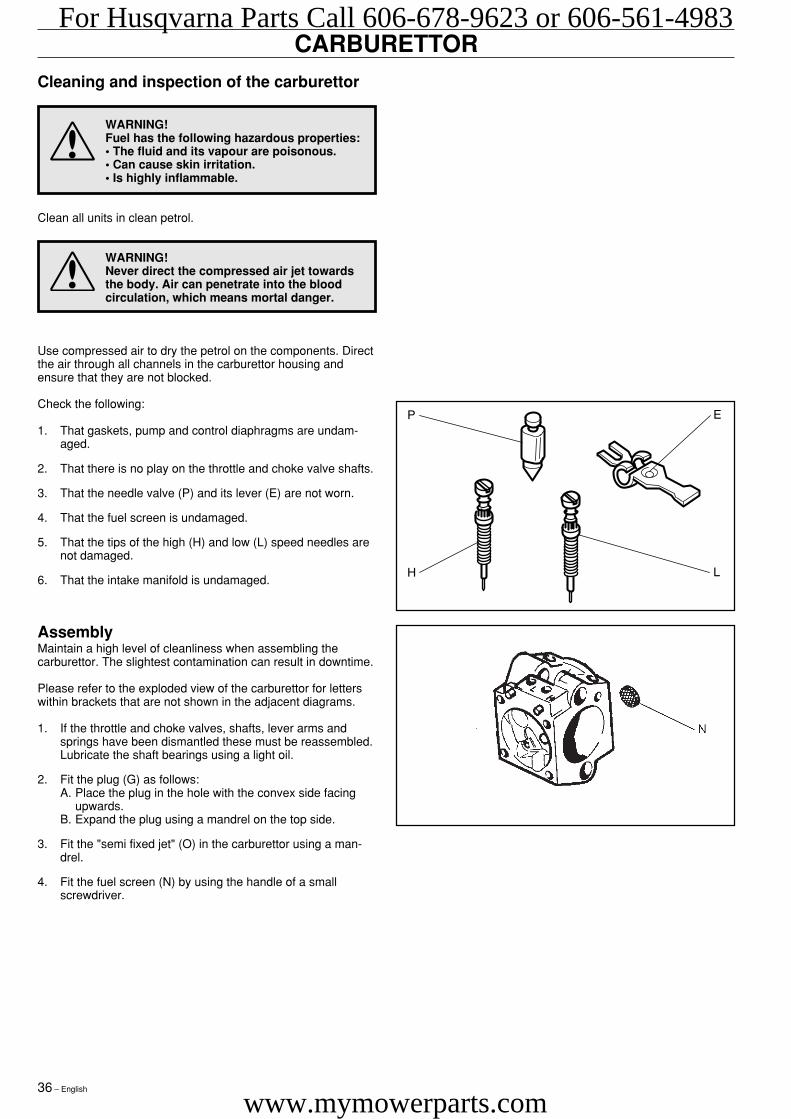
Check the following:
1. That gaskets, pump and control diaphragms are undam-aged.
2. That there is no play on the throttle and choke valve shafts.
3. That the needle valve (P) and its lever (E) are not worn.
4. That the fuel screen is undamaged.
5. That the tips of the high (H) and low (L) speed needles arenot damaged.
6. That the intake manifold is undamaged.
AssemblyMaintain a high level of cleanliness when assembling thecarburettor. The slightest contamination can result in downtime.
Please refer to the exploded view of the carburettor for letterswithin brackets that are not shown in the adjacent diagrams.
1. If the throttle and choke valves, shafts, lever arms andsprings have been dismantled these must be reassembled.Lubricate the shaft bearings using a light oil.
2. Fit the plug (G) as follows:A. Place the plug in the hole with the convex side facing
upwards.B. Expand the plug using a mandrel on the top side.
3. Fit the "semi fixed jet" (O) in the carburettor using a man-drel.
4. Fit the fuel screen (N) by using the handle of a smallscrewdriver.
CARBURETTORFor Husqvarna Parts Call 606-678-9623 or 606-561-4983
www.mymowerparts.com
English – 37
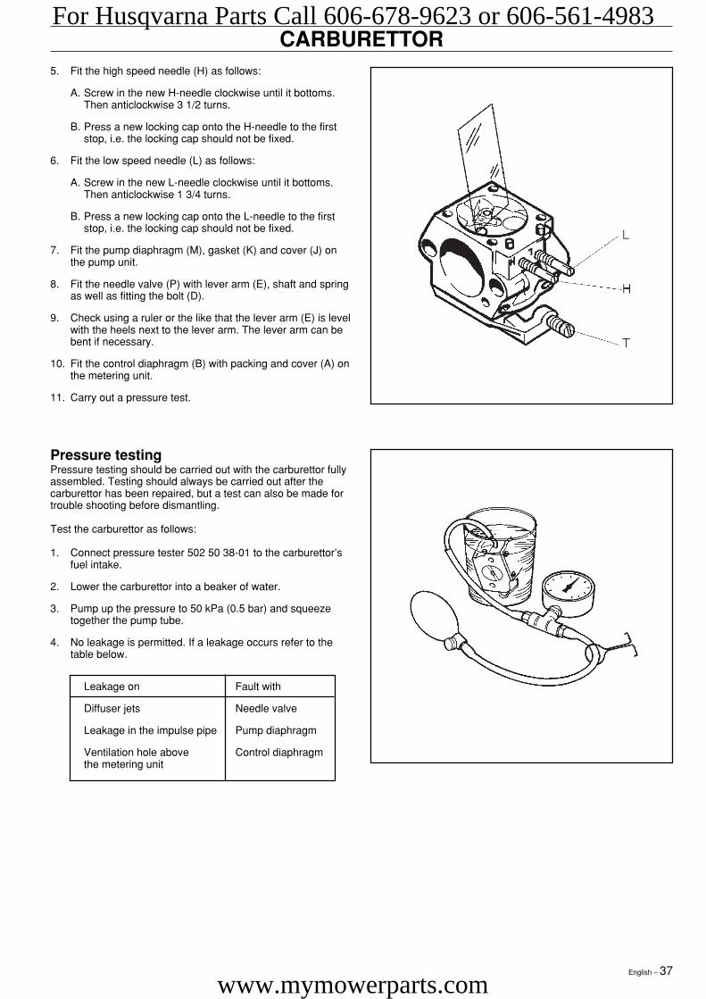
CARBURETTOR5. Fit the high speed needle (H) as follows:
A. Screw in the new H-needle clockwise until it bottoms.Then anticlockwise 3 1/2 turns.
B. Press a new locking cap onto the H-needle to the firststop, i.e. the locking cap should not be fixed.
6. Fit the low speed needle (L) as follows:
A. Screw in the new L-needle clockwise until it bottoms.Then anticlockwise 1 3/4 turns.
B. Press a new locking cap onto the L-needle to the firststop, i.e. the locking cap should not be fixed.
7. Fit the pump diaphragm (M), gasket (K) and cover (J) onthe pump unit.
8. Fit the needle valve (P) with lever arm (E), shaft and springas well as fitting the bolt (D).
9. Check using a ruler or the like that the lever arm (E) is levelwith the heels next to the lever arm. The lever arm can bebent if necessary.
10. Fit the control diaphragm (B) with packing and cover (A) onthe metering unit.
11. Carry out a pressure test.
Pressure testingPressure testing should be carried out with the carburettor fullyassembled. Testing should always be carried out after thecarburettor has been repaired, but a test can also be made fortrouble shooting before dismantling.
Test the carburettor as follows:
1. Connect pressure tester 502 50 38-01 to the carburettor’sfuel intake.
2. Lower the carburettor into a beaker of water.
3. Pump up the pressure to 50 kPa (0.5 bar) and squeezetogether the pump tube.
4. No leakage is permitted. If a leakage occurs refer to thetable below.
Leakage on Fault with
Diffuser jets Needle valve
Leakage in the impulse pipe Pump diaphragm
Ventilation hole above Control diaphragmthe metering unit
For Husqvarna Parts Call 606-678-9623 or 606-561-4983
www.mymowerparts.com
38 – English
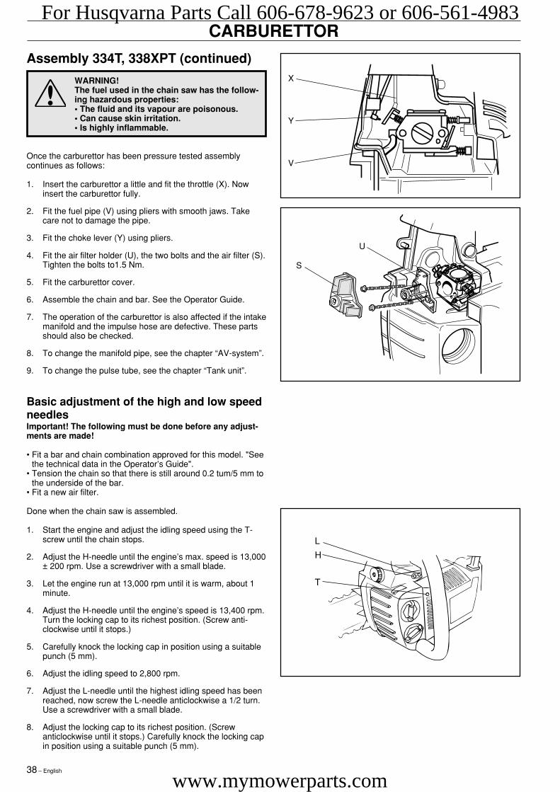
Assembly 334T, 338XPT (continued)
WARNING!The fuel used in the chain saw has the follow-ing hazardous properties:• The fluid and its vapour are poisonous.• Can cause skin irritation.• Is highly inflammable.
Once the carburettor has been pressure tested assemblycontinues as follows:
1. Insert the carburettor a little and fit the throttle (X). Nowinsert the carburettor fully.
2. Fit the fuel pipe (V) using pliers with smooth jaws. Takecare not to damage the pipe.
3. Fit the choke lever (Y) using pliers.
4. Fit the air filter holder (U), the two bolts and the air filter (S).Tighten the bolts to1.5 Nm.
5. Fit the carburettor cover.
6. Assemble the chain and bar. See the Operator Guide.
7. The operation of the carburettor is also affected if the intakemanifold and the impulse hose are defective. These partsshould also be checked.
8. To change the manifold pipe, see the chapter “AV-system”.
9. To change the pulse tube, see the chapter “Tank unit”.
CARBURETTOR
Basic adjustment of the high and low speedneedlesImportant! The following must be done before any adjust-ments are made!
• Fit a bar and chain combination approved for this model. "Seethe technical data in the Operator’s Guide".
• Tension the chain so that there is still around 0.2 tum/5 mm tothe underside of the bar.
• Fit a new air filter.
Done when the chain saw is assembled.
1. Start the engine and adjust the idling speed using the T-screw until the chain stops.
2. Adjust the H-needle until the engine’s max. speed is 13,000± 200 rpm. Use a screwdriver with a small blade.
3. Let the engine run at 13,000 rpm until it is warm, about 1minute.
4. Adjust the H-needle until the engine’s speed is 13,400 rpm.Turn the locking cap to its richest position. (Screw anti-clockwise until it stops.)
5. Carefully knock the locking cap in position using a suitablepunch (5 mm).
6. Adjust the idling speed to 2,800 rpm.
7. Adjust the L-needle until the highest idling speed has beenreached, now screw the L-needle anticlockwise a 1/2 turn.Use a screwdriver with a small blade.
8. Adjust the locking cap to its richest position. (Screwanticlockwise until it stops.) Carefully knock the locking capin position using a suitable punch (5 mm).
L
H
T
U
S
X
Y
V
For Husqvarna Parts Call 606-678-9623 or 606-561-4983
www.mymowerparts.com
English – 39
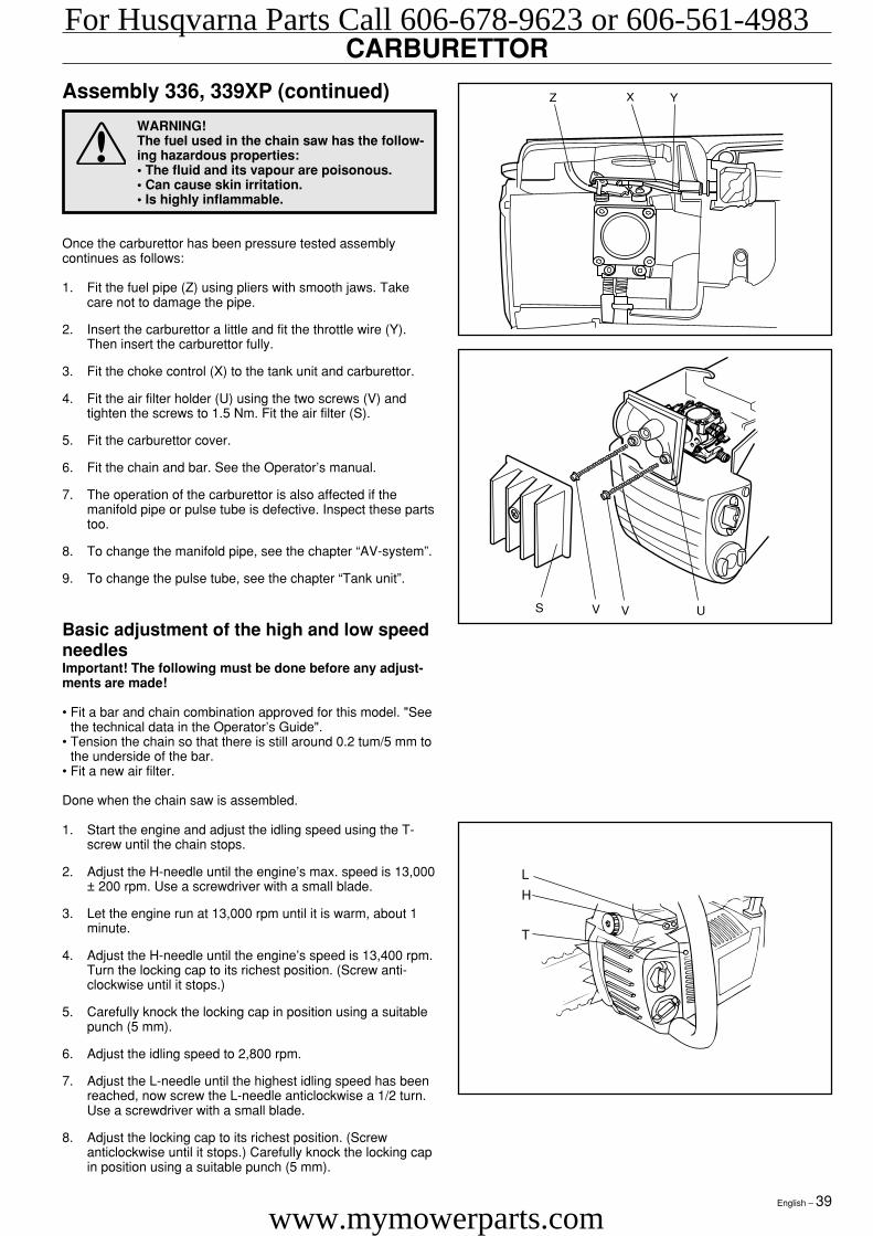
Assembly 336, 339XP (continued)
WARNING!The fuel used in the chain saw has the follow-ing hazardous properties:• The fluid and its vapour are poisonous.• Can cause skin irritation.• Is highly inflammable.
Once the carburettor has been pressure tested assemblycontinues as follows:
1. Fit the fuel pipe (Z) using pliers with smooth jaws. Takecare not to damage the pipe.
2. Insert the carburettor a little and fit the throttle wire (Y).Then insert the carburettor fully.
3. Fit the choke control (X) to the tank unit and carburettor.
4. Fit the air filter holder (U) using the two screws (V) andtighten the screws to 1.5 Nm. Fit the air filter (S).
5. Fit the carburettor cover.
6. Fit the chain and bar. See the Operator’s manual.
7. The operation of the carburettor is also affected if themanifold pipe or pulse tube is defective. Inspect these partstoo.
8. To change the manifold pipe, see the chapter “AV-system”.
9. To change the pulse tube, see the chapter “Tank unit”.
CARBURETTOR
Basic adjustment of the high and low speedneedlesImportant! The following must be done before any adjust-ments are made!
• Fit a bar and chain combination approved for this model. "Seethe technical data in the Operator’s Guide".
• Tension the chain so that there is still around 0.2 tum/5 mm tothe underside of the bar.
• Fit a new air filter.
Done when the chain saw is assembled.
1. Start the engine and adjust the idling speed using the T-screw until the chain stops.
2. Adjust the H-needle until the engine’s max. speed is 13,000± 200 rpm. Use a screwdriver with a small blade.
3. Let the engine run at 13,000 rpm until it is warm, about 1minute.
4. Adjust the H-needle until the engine’s speed is 13,400 rpm.Turn the locking cap to its richest position. (Screw anti-clockwise until it stops.)
5. Carefully knock the locking cap in position using a suitablepunch (5 mm).
6. Adjust the idling speed to 2,800 rpm.
7. Adjust the L-needle until the highest idling speed has beenreached, now screw the L-needle anticlockwise a 1/2 turn.Use a screwdriver with a small blade.
8. Adjust the locking cap to its richest position. (Screwanticlockwise until it stops.) Carefully knock the locking capin position using a suitable punch (5 mm).
S V V U
Z X Y
L
H
T
For Husqvarna Parts Call 606-678-9623 or 606-561-4983
www.mymowerparts.com
40 – English
Carburettor
Your Husqvarna product has been designed and manufacturedaccording to specifications that reduce harmful gases.When you engine has consumed 8-10 tanks of fuel the enginehas been "run-in". To ensure that it runs in the best possibleway and emits as few harmful gases as possible after therunning in period, let your dealer/service workshop that has atachometer, adjust your carburettor so that it gives optimalperformance.
WARNING! The bar, chain and clutch cover(chain brake) must be fitted before the saw isstarted otherwise the clutch can work looseand cause personal injury.
Function, Basic setting, Fine tuning
Function• The carburettor controls the speed of the engine via the
throttle. Air/fuel is mixed in the carburettor. This air/fuelmixture is adjustable. The adjustment must be correct to utilisethe saw’s maximum power.
• Adjustment of the carburettor means that the engine isadapted to local conditions, e.g. the climate, altitude, petroland the type of 2-stroke oil.
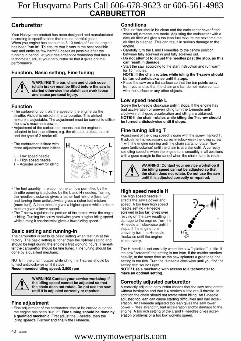
• The carburettor is fitted withthree adjustment possibilities:
L = Low speed needle H = High speed needle T = Adjuster screw for idling
• The fuel quantity in relation to the air flow permitted by thethrottle opening is adjusted by the L and H-needles. Turningthe needles clockwise gives a leaner fuel mixture (less fuel)and turning them anticlockwise gives a richer fuel mixture(more fuel). A lean mixture gives a higher speed while a richermixture gives a lower speed.
• The T-screw regulates the position of the throttle while the engineis idling. Turning the screw clockwise gives a higher idling speedwhile turning it anticlockwise gives a lower idling speed.
Basic setting and running-inThe carburettor is set to its basic setting when test run at thefactory. The basic setting is richer than the optimal setting andshould be kept during the engine’s first working hours. Thereaf-ter the carburettor should be fine tuned. Fine tuning should bedone by a qualified mechanic.
NOTE! If the chain rotates while idling the T-screw should beturned anticlockwise until it stops.Recommended idling speed: 2,800 rpm
H L
T
WARNING! Contact your service workshop ifthe idling speed cannot be adjusted so thatthe chain does not rotate. Do not use the sawuntil it is adjusted correctly or repaired.
Fine adjustment• Fine adjustment of the carburettor should be carried out once
the engine has been "run-in". Fine tuning should be done bya qualified mechanic. First adjust the L-needle, then theidling speed's T-screw and finally the H-needle.
CARBURETTOR
Low speed needle LScrew the L-needle clockwise until it stops. If the engine hasbad acceleration or uneven idling turn the L-needle anti-clockwise until good acceleration and idling are obtained.NOTE! If the chain rotates while idling the T-screw shouldbe turned anticlockwise until it stops.
Fine tuning idling TAdjustment of the idling speed is done with the screw marked T.If adjustment is necessary, screw in (clockwise) the idling screwT with the engine running until the chain starts to rotate. Nowopen (anticlockwise) until the chain is at a standstill. A correctlyset idling speed is when the engine runs smoothly in all positionswith a good margin to the speed when the chain starts to rotate.
High speed needle HThe high speed needle Haffects the saw's power andspeed. A too lean high speedneedle setting (H-needlescrewed in too far) gives overrevving on the saw resulting indamage to the engine. Turn theH-needle anticlockwise until itstops. If the engine runsunevenly turn the H-needleclockwise until the enginexruns evenly.
The H-needle is set correctly when the saw "splatters" a little. Ifthe saw "screams" the setting is too lean. If the muffler smokesheavily, at the same time as the saw splatters a great deal thesetting is too rich. Turn the H-needle clockwise until you find thesetting that sounds right.NOTE! Use a mechanic with access to a tachometer tomake an optimal setting.
Correctly adjusted carburettorA correctly adjusted carburettor means that the saw accelerateswithout hesitation and that it 4-strokes a little at full throttle. Inaddition the chain should not rotate when idling. An L-needleadjusted too lean can cause starting difficulties and bad accel-eration. An H-needle adjusted too lean gives the saw lowerpower = "less strength", bad acceleration and/or damage to theengine. A too rich setting of the L and H-needles gives accel-eration problems or a too low working speed.
WARNING! Contact your service workshop ifthe idling speed cannot be adjusted so thatthe chain does not rotate. Do not use the sawuntil it is adjusted correctly or repaired.
Conditions• The air filter should be clean and the carburettor cover fitted
when adjustments are made. Adjusting the carburettor with adirty air filter will give a too lean fuel mixture the next time theair filter is cleaned. This can result in serious damage to theengine.
• Carefully turn the L and H-needles to the centre positionbetween fully screwed in and fully screwed out.
• Do not attempt to adjust the needles past the stop, as thiscan result in damage.
• Start the saw according to the start instruction and run warmfor 10 minutes.NOTE! If the chain rotates while idling the T-screw shouldbe turned anticlockwise until it stops.
• Place the saw on a flat surface so that the bar points awayfrom you and so that the chain and bar do not make contactwith the surface or any other objects.
H
For Husqvarna Parts Call 606-678-9623 or 606-561-4983
www.mymowerparts.com
English – 41
TANK UNIT
WARNING!The fuel used in the chain saw has the follow-ing hazardous properties:• The fluid and its vapour are poisonous.• Can cause skin irritation.• Is highly inflammable.
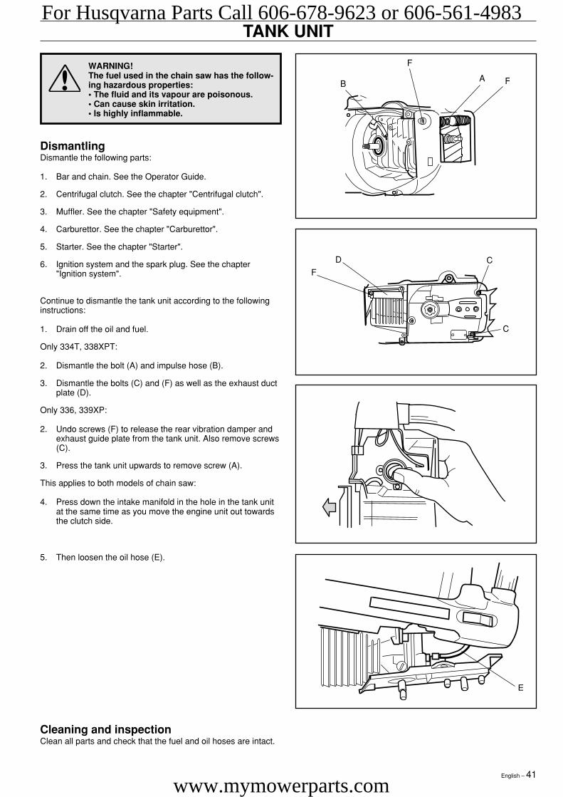
DismantlingDismantle the following parts:
1. Bar and chain. See the Operator Guide.
2. Centrifugal clutch. See the chapter "Centrifugal clutch".
3. Muffler. See the chapter "Safety equipment".
4. Carburettor. See the chapter "Carburettor".
5. Starter. See the chapter "Starter".
6. Ignition system and the spark plug. See the chapter"Ignition system".
Continue to dismantle the tank unit according to the followinginstructions:
1. Drain off the oil and fuel.
Only 334T, 338XPT:
2. Dismantle the bolt (A) and impulse hose (B).
3. Dismantle the bolts (C) and (F) as well as the exhaust ductplate (D).
Only 336, 339XP:
2. Undo screws (F) to release the rear vibration damper andexhaust guide plate from the tank unit. Also remove screws(C).
3. Press the tank unit upwards to remove screw (A).
This applies to both models of chain saw:
4. Press down the intake manifold in the hole in the tank unitat the same time as you move the engine unit out towardsthe clutch side.
Cleaning and inspectionClean all parts and check that the fuel and oil hoses are intact.
5. Then loosen the oil hose (E).
AB F
F
D
FC
C
For Husqvarna Parts Call 606-678-9623 or 606-561-4983
www.mymowerparts.com
42 – English
TANK UNIT
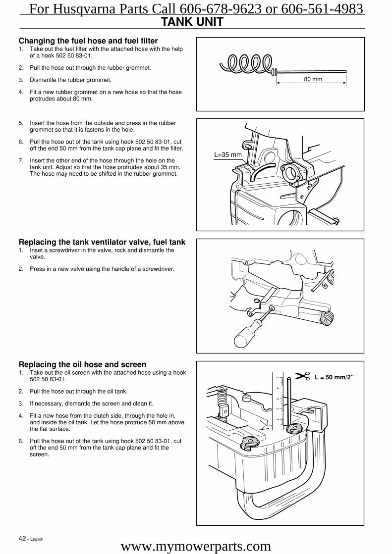
Changing the fuel hose and fuel filter1. Take out the fuel filter with the attached hose with the help
of a hook 502 50 83-01.
2. Pull the hose out through the rubber grommet.
3. Dismantle the rubber grommet.
4. Fit a new rubber grommet on a new hose so that the hoseprotrudes about 80 mm.
5. Insert the hose from the outside and press in the rubbergrommet so that it is fastens in the hole.
6. Pull the hose out of the tank using hook 502 50 83-01, cutoff the end 50 mm from the tank cap plane and fit the filter.
7. Insert the other end of the hose through the hole on thetank unit. Adjust so that the hose protrudes about 35 mm.The hose may need to be shifted in the rubber grommet.
80 mm
L=35 mm
Replacing the oil hose and screen1. Take out the oil screen with the attached hose using a hook
502 50 83-01.
2. Pull the hose out through the oil tank.
3. If necessary, dismantle the screen and clean it.
4. Fit a new hose from the clutch side, through the hole in,and inside the oil tank. Let the hose protrude 50 mm abovethe flat surface.
6. Pull the hose out of the tank using hook 502 50 83-01, cutoff the end 50 mm from the tank cap plane and fit thescreen.
Replacing the tank ventilator valve, fuel tank1. Inset a screwdriver in the valve, rock and dismantle the
valve.
2. Press in a new valve using the handle of a screwdriver.
L = 50 mm/2”
✂
5 4 3 2 1
For Husqvarna Parts Call 606-678-9623 or 606-561-4983
www.mymowerparts.com
English – 43
TANK UNIT
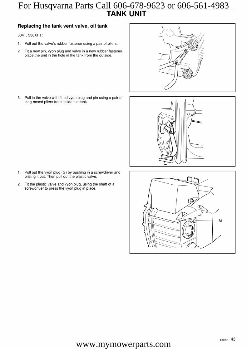
Replacing the tank vent valve, oil tank
334T, 338XPT:
1. Pull out the valve’s rubber fastener using a pair of pliers.
2. Fit a new pin, vyon plug and valve in a new rubber fastener,place the unit in the hole in the tank from the outside.
3. Pull in the valve with fitted vyon plug and pin using a pair oflong-nosed pliers from inside the tank.
1. Pull out the vyon plug (G) by pushing in a screwdriver andprising it out. Then pull out the plastic valve.
2. Fit the plastic valve and vyon plug, using the shaft of ascrewdriver to press the vyon plug in place.
G
For Husqvarna Parts Call 606-678-9623 or 606-561-4983
www.mymowerparts.com
44 – English
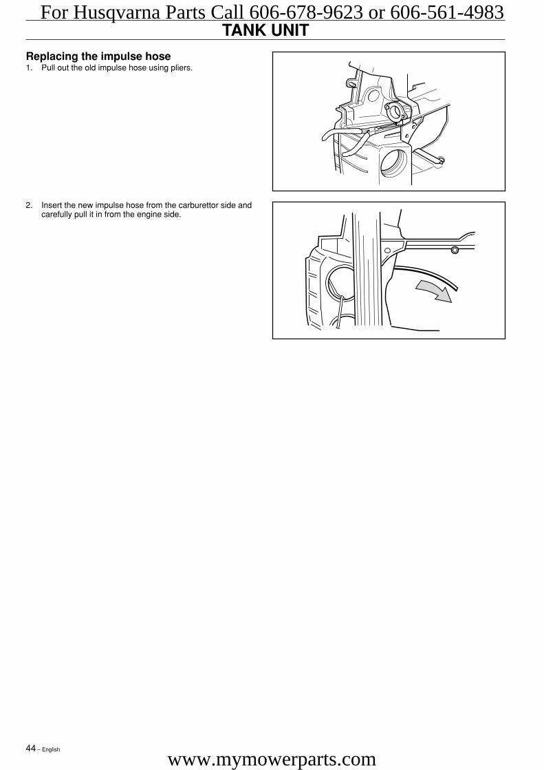
Replacing the impulse hose1. Pull out the old impulse hose using pliers.
2. Insert the new impulse hose from the carburettor side andcarefully pull it in from the engine side.
TANK UNITFor Husqvarna Parts Call 606-678-9623 or 606-561-4983
www.mymowerparts.com
English – 45
TANK UNIT
WARNING!The fuel used in the chain saw has the follow-ing hazardous properties:• The fluid and its vapour are poisonous.• Can cause skin irritation.• Is highly inflammable.
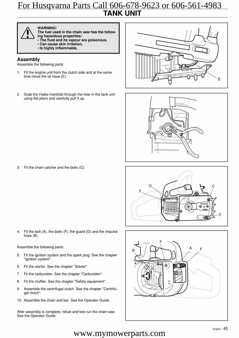
AssemblyAssemble the following parts:
1. Fit the engine unit from the clutch side and at the sametime move the oil hose (E).
4. Fit the bolt (A), the bolts (F), the guard (D) and the impulsehose (B).
Assemble the following parts:
5. Fit the ignition system and the spark plug. See the chapter"Ignition system".
6. Fit the starter. See the chapter "Starter".
7. Fit the carburettor. See the chapter "Carburettor".
8. Fit the muffler. See the chapter "Safety equipment".
9. Assemble the centrifugal clutch. See the chapter "Centrifu-gal clutch".
10. Assemble the chain and bar. See the Operator Guide.
After assembly is complete, refuel and test run the chain saw.See the Operator Guide.
3. Fit the chain catcher and the bolts (C).
2. Grab the intake manifold through the hole in the tank unitusing flat pliers and carefully pull it up.
D
FC
C
AB F
F
For Husqvarna Parts Call 606-678-9623 or 606-561-4983
www.mymowerparts.com
46 – English
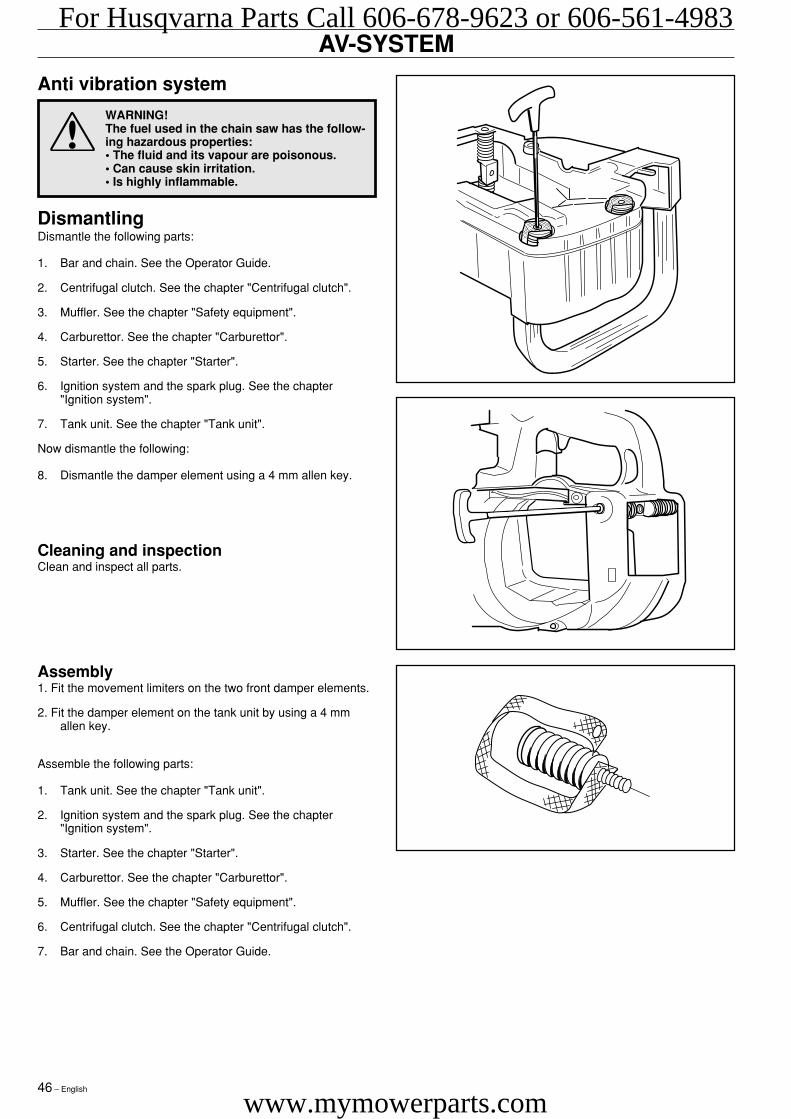
AV-SYSTEM
Assembly1. Fit the movement limiters on the two front damper elements.
2. Fit the damper element on the tank unit by using a 4 mmallen key.
Assemble the following parts:
1. Tank unit. See the chapter "Tank unit".
2. Ignition system and the spark plug. See the chapter"Ignition system".
3. Starter. See the chapter "Starter".
4. Carburettor. See the chapter "Carburettor".
5. Muffler. See the chapter "Safety equipment".
6. Centrifugal clutch. See the chapter "Centrifugal clutch".
7. Bar and chain. See the Operator Guide.
Anti vibration system
WARNING!The fuel used in the chain saw has the follow-ing hazardous properties:• The fluid and its vapour are poisonous.• Can cause skin irritation.• Is highly inflammable.
DismantlingDismantle the following parts:
1. Bar and chain. See the Operator Guide.
2. Centrifugal clutch. See the chapter "Centrifugal clutch".
3. Muffler. See the chapter "Safety equipment".
4. Carburettor. See the chapter "Carburettor".
5. Starter. See the chapter "Starter".
6. Ignition system and the spark plug. See the chapter"Ignition system".
7. Tank unit. See the chapter "Tank unit".
Now dismantle the following:
8. Dismantle the damper element using a 4 mm allen key.
Cleaning and inspectionClean and inspect all parts.
For Husqvarna Parts Call 606-678-9623 or 606-561-4983
www.mymowerparts.com
English – 47
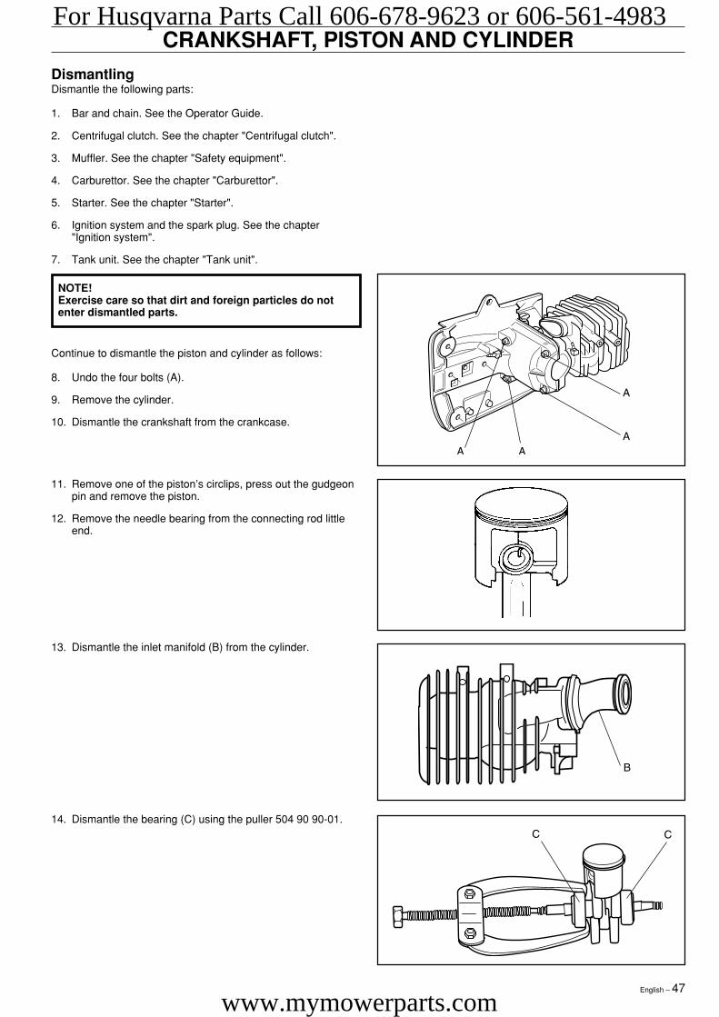
CRANKSHAFT, PISTON AND CYLINDERDismantlingDismantle the following parts:
1. Bar and chain. See the Operator Guide.
2. Centrifugal clutch. See the chapter "Centrifugal clutch".
3. Muffler. See the chapter "Safety equipment".
4. Carburettor. See the chapter "Carburettor".
5. Starter. See the chapter "Starter".
6. Ignition system and the spark plug. See the chapter"Ignition system".
7. Tank unit. See the chapter "Tank unit".
14. Dismantle the bearing (C) using the puller 504 90 90-01.
NOTE!Exercise care so that dirt and foreign particles do notenter dismantled parts.
Continue to dismantle the piston and cylinder as follows:
8. Undo the four bolts (A).
9. Remove the cylinder.
10. Dismantle the crankshaft from the crankcase.
11. Remove one of the piston’s circlips, press out the gudgeonpin and remove the piston.
12. Remove the needle bearing from the connecting rod littleend.
13. Dismantle the inlet manifold (B) from the cylinder.
For Husqvarna Parts Call 606-678-9623 or 606-561-4983
www.mymowerparts.com
48 – English
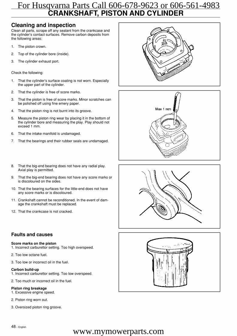
Cleaning and inspectionClean all parts, scrape off any sealant from the crankcase andthe cylinder’s contact surfaces. Remove carbon deposits fromthe following areas:
1. The piston crown.
2. Top of the cylinder bore (inside).
3. The cylinder exhaust port.
Check the following:
1. That the cylinder’s surface coating is not worn. Especiallythe upper part of the cylinder.
2. That the cylinder is free of score marks.
3. That the piston is free of score marks. Minor scratches canbe polished off using fine emery paper.
4. That the piston ring is not burnt into its groove.
5. Measure the piston ring wear by placing it in the bottom ofthe cylinder bore and measuring the play. Play should notexceed 1 mm.
6. That the intake manifold is undamaged.
7. That the bearings and their rubber seals are undamaged.
CRANKSHAFT, PISTON AND CYLINDER
Faults and causes
Score marks on the piston1. Incorrect carburettor setting. Too high overspeed.
2. Too low octane fuel.
3. Too low or incorrect oil in the fuel.
Carbon build-up1. Incorrect carburettor setting. Too low overspeed.
2. Too much or incorrect oil in the fuel.
Piston ring breakage1. Excessive engine speed.
2. Piston ring worn out.
3. Oversized piston ring groove.
8. That the big-end bearing does not have any radial play.Axial play is permitted.
9. That the big-end bearing does not have any score marks oris discoloured on the sides.
10. That the bearing surfaces for the little-end does not haveany score marks or is discoloured.
11. Crankshaft cannot be reconditioned. In the event of dam-age the crankshaft must be replaced.
12. That the crankcase is not cracked.
For Husqvarna Parts Call 606-678-9623 or 606-561-4983
www.mymowerparts.com
English – 49
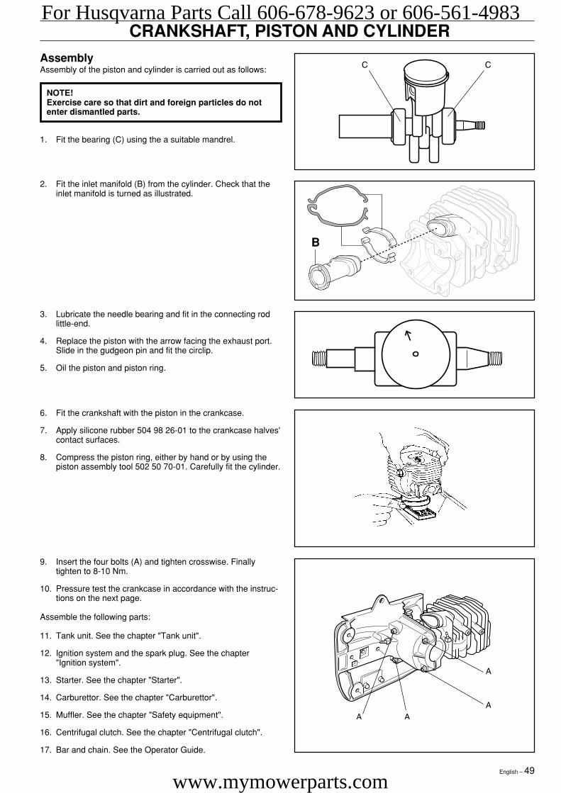
CRANKSHAFT, PISTON AND CYLINDERAssemblyAssembly of the piston and cylinder is carried out as follows:
9. Insert the four bolts (A) and tighten crosswise. Finallytighten to 8-10 Nm.
10. Pressure test the crankcase in accordance with the instruc-tions on the next page.
Assemble the following parts:
11. Tank unit. See the chapter "Tank unit".
12. Ignition system and the spark plug. See the chapter"Ignition system".
13. Starter. See the chapter "Starter".
14. Carburettor. See the chapter "Carburettor".
15. Muffler. See the chapter "Safety equipment".
16. Centrifugal clutch. See the chapter "Centrifugal clutch".
17. Bar and chain. See the Operator Guide.
6. Fit the crankshaft with the piston in the crankcase.
7. Apply silicone rubber 504 98 26-01 to the crankcase halves'contact surfaces.
8. Compress the piston ring, either by hand or by using thepiston assembly tool 502 50 70-01. Carefully fit the cylinder.
3. Lubricate the needle bearing and fit in the connecting rodlittle-end.
4. Replace the piston with the arrow facing the exhaust port.Slide in the gudgeon pin and fit the circlip.
5. Oil the piston and piston ring.
2. Fit the inlet manifold (B) from the cylinder. Check that theinlet manifold is turned as illustrated.
NOTE!Exercise care so that dirt and foreign particles do notenter dismantled parts.
1. Fit the bearing (C) using the a suitable mandrel.
B
For Husqvarna Parts Call 606-678-9623 or 606-561-4983
www.mymowerparts.com
50 – English
CRANKSHAFT, PISTON AND CYLINDER
3. Pull off the hose to the impulse channel and seal the nipple.
4. Pump up the pressure to 80 kPa (0.8 bar).
5. Wait 30 seconds.
6. The pressure must not fall below 60 kPa (0.6 bar).
7. Leakage can occur on the crankshaft’s sealing rings.
8. Dismantle the cover plates.
Assemble the following parts:
• Flywheel. See the chapter "Ignition system".
• Starter. See the chapter "Starter".
• Carburettor. See the chapter "Carburettor".
• Muffler. See the chapter "Safety equipment".
Pressure testingThe following parts must be removed to pressure test thecrankcase and cylinder:
• Carburettor. See the chapter "Carburettor".
• Muffler. See the chapter "Safety equipment".
• Starter. See the chapter "Starter".
• Flywheel. See the chapter "Ignition system".
Carry out pressure testing as follows:
1. Fit the cover plate 502 52 01-01 on the inlet manifold. Nowconnect tool 502 50 38-01 to the cover plate.
2. Fit the cover plate 502 71 39-01 on the exhaust port.
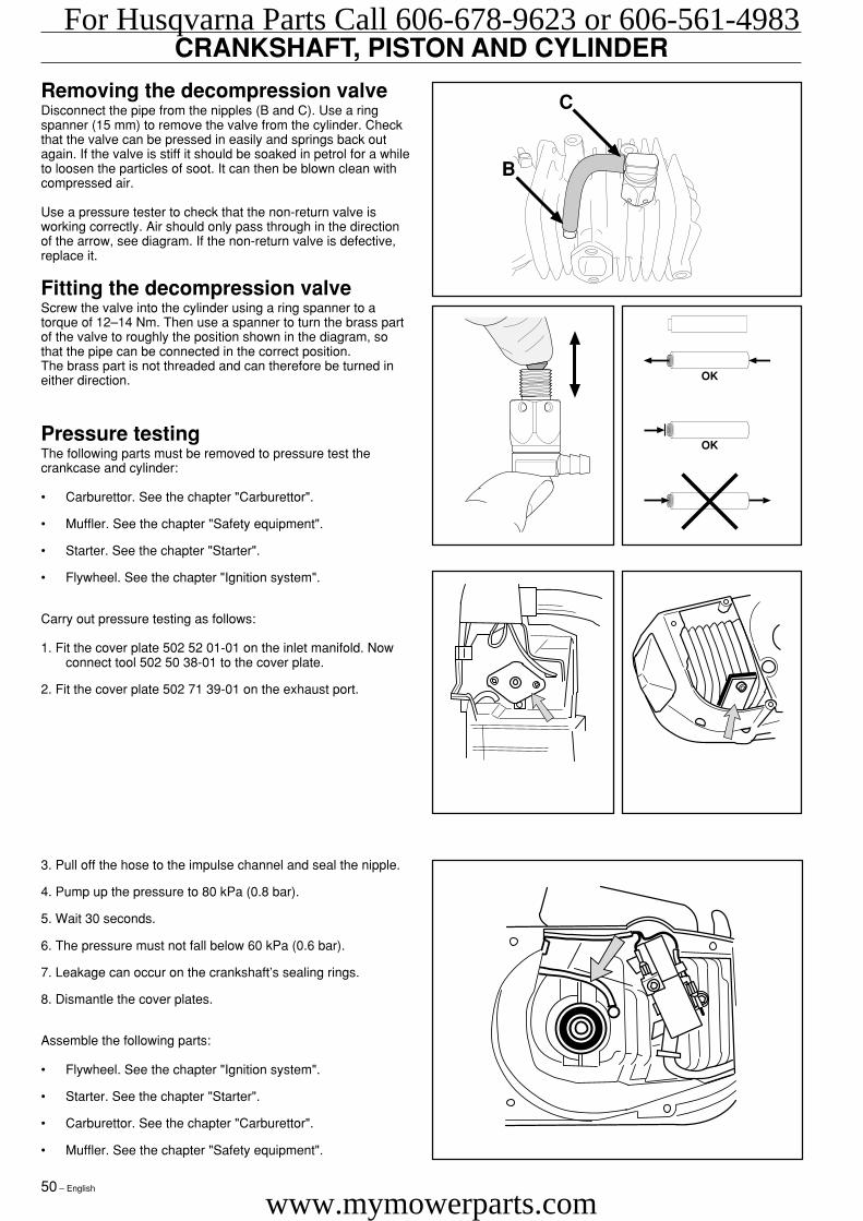
Removing the decompression valveDisconnect the pipe from the nipples (B and C). Use a ringspanner (15 mm) to remove the valve from the cylinder. Checkthat the valve can be pressed in easily and springs back outagain. If the valve is stiff it should be soaked in petrol for a whileto loosen the particles of soot. It can then be blown clean withcompressed air.
Use a pressure tester to check that the non-return valve isworking correctly. Air should only pass through in the directionof the arrow, see diagram. If the non-return valve is defective,replace it.
Fitting the decompression valveScrew the valve into the cylinder using a ring spanner to atorque of 12–14 Nm. Then use a spanner to turn the brass partof the valve to roughly the position shown in the diagram, sothat the pipe can be connected in the correct position.The brass part is not threaded and can therefore be turned ineither direction.
B
C
OK
OK
For Husqvarna Parts Call 606-678-9623 or 606-561-4983
www.mymowerparts.com
English – 51
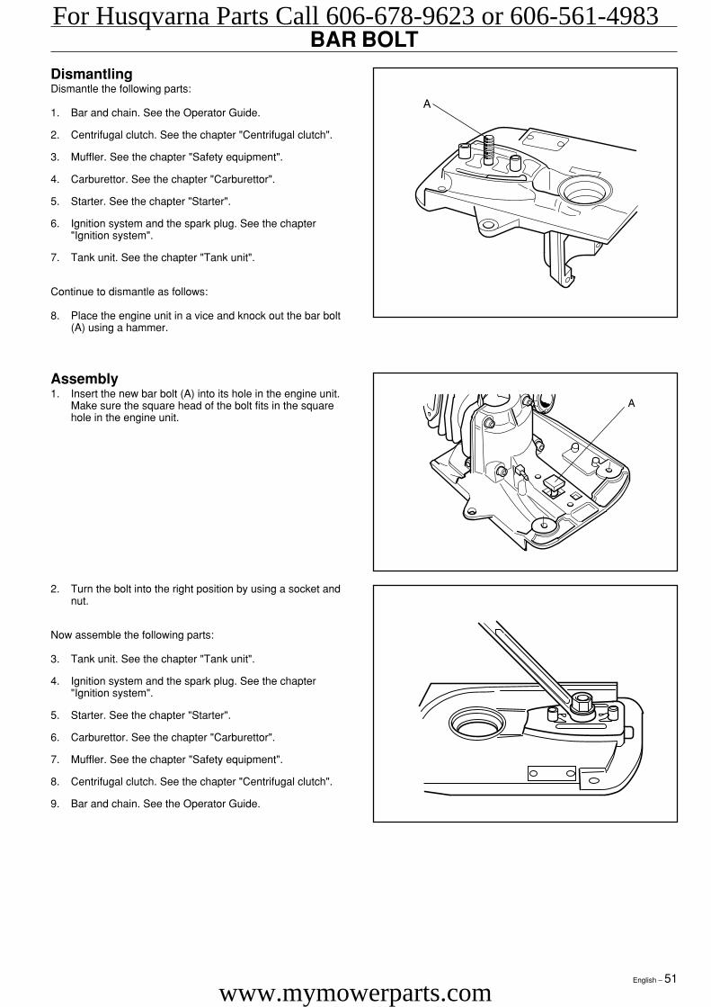
BAR BOLTDismantlingDismantle the following parts:
1. Bar and chain. See the Operator Guide.
2. Centrifugal clutch. See the chapter "Centrifugal clutch".
3. Muffler. See the chapter "Safety equipment".
4. Carburettor. See the chapter "Carburettor".
5. Starter. See the chapter "Starter".
6. Ignition system and the spark plug. See the chapter"Ignition system".
7. Tank unit. See the chapter "Tank unit".
Continue to dismantle as follows:
8. Place the engine unit in a vice and knock out the bar bolt(A) using a hammer.
Assembly1. Insert the new bar bolt (A) into its hole in the engine unit.
Make sure the square head of the bolt fits in the squarehole in the engine unit.
2. Turn the bolt into the right position by using a socket andnut.
Now assemble the following parts:
3. Tank unit. See the chapter "Tank unit".
4. Ignition system and the spark plug. See the chapter"Ignition system".
5. Starter. See the chapter "Starter".
6. Carburettor. See the chapter "Carburettor".
7. Muffler. See the chapter "Safety equipment".
8. Centrifugal clutch. See the chapter "Centrifugal clutch".
9. Bar and chain. See the Operator Guide.
For Husqvarna Parts Call 606-678-9623 or 606-561-4983
www.mymowerparts.com
52 – English
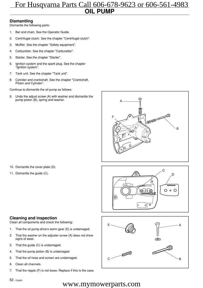
OIL PUMPDismantlingDismantle the following parts:
1. Bar and chain. See the Operator Guide.
2. Centrifugal clutch. See the chapter "Centrifugal clutch".
3. Muffler. See the chapter "Safety equipment".
4. Carburettor. See the chapter "Carburettor".
5. Starter. See the chapter "Starter".
6. Ignition system and the spark plug. See the chapter"Ignition system".
7. Tank unit. See the chapter "Tank unit".
8. Cylinder and crankshaft. See the chapter "Crankshaft,Piston and Cylinder".
Continue to dismantle the oil pump as follows:
9. Undo the adjust screw (A) with washer and dismantle thepump piston (B), spring and washer.
Cleaning and inspectionClean all components and check the following:
1. That the oil pump drive’s worm gear (E) is undamaged.
2. That the washer on the adjuster screw (A) does not showsigns of wear.
3. That the guide (C) is undamaged.
4. That the pump piston (B) is undamaged
5. That the oil hose and screen are undamaged.
6. Clean all channels.
7. That the nipple (F) is not loose. Replace if this is the case.
CD
10. Dismantle the cover plate (D).
11. Dismantle the guide (C).
A
B
F
E
C
A
B
For Husqvarna Parts Call 606-678-9623 or 606-561-4983
www.mymowerparts.com
English – 53
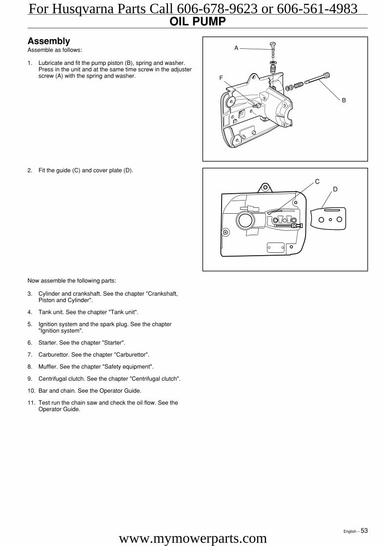
AssemblyAssemble as follows:
1. Lubricate and fit the pump piston (B), spring and washer.Press in the unit and at the same time screw in the adjusterscrew (A) with the spring and washer.
OIL PUMP
Now assemble the following parts:
3. Cylinder and crankshaft. See the chapter "Crankshaft,Piston and Cylinder".
4. Tank unit. See the chapter "Tank unit".
5. Ignition system and the spark plug. See the chapter"Ignition system".
6. Starter. See the chapter "Starter".
7. Carburettor. See the chapter "Carburettor".
8. Muffler. See the chapter "Safety equipment".
9. Centrifugal clutch. See the chapter "Centrifugal clutch".
10. Bar and chain. See the Operator Guide.
11. Test run the chain saw and check the oil flow. See theOperator Guide.
CD
2. Fit the guide (C) and cover plate (D).
A
B
F
For Husqvarna Parts Call 606-678-9623 or 606-561-4983
www.mymowerparts.com

´®z+H.@¶6f¨2003W03
114 01 43-26
For Husqvarna Parts Call 606-678-9623 or 606-561-4983
www.mymowerparts.com