Embed Size (px)
Citation preview

WORKSHOP 5
COORDINATE SYSTEMS

WS5-2NAS120, Workshop 5, May 2006Copyright© 2005 MSC.Software Corporation
WS5-3NAS120, Workshop 5, May 2006Copyright© 2005 MSC.Software Corporation
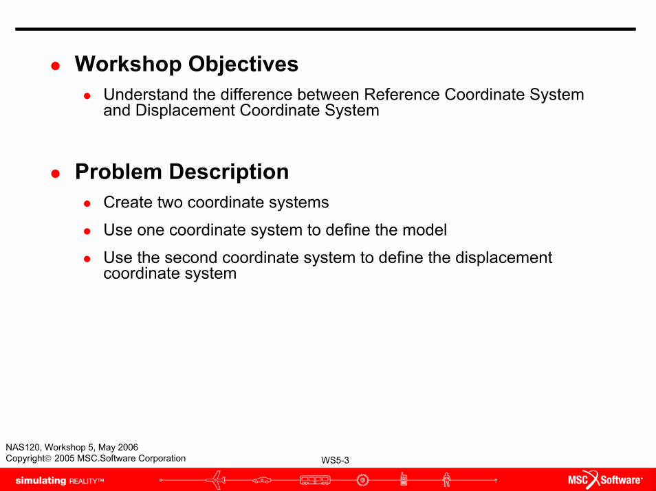
Workshop ObjectivesUnderstand the difference between Reference Coordinate System and Displacement Coordinate System
Problem DescriptionCreate two coordinate systems
Use one coordinate system to define the model
Use the second coordinate system to define the displacement coordinate system
WS5-4NAS120, Workshop 5, May 2006Copyright© 2005 MSC.Software Corporation
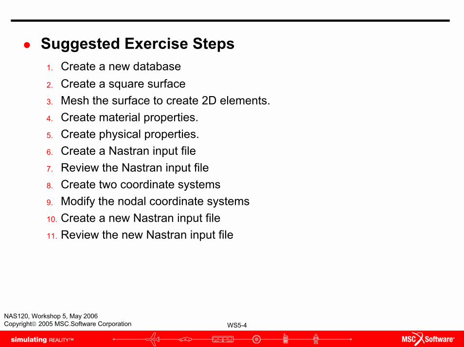
Suggested Exercise Steps1. Create a new database 2. Create a square surface3. Mesh the surface to create 2D elements. 4. Create material properties. 5. Create physical properties.6. Create a Nastran input file7. Review the Nastran input file8. Create two coordinate systems9. Modify the nodal coordinate systems10. Create a new Nastran input file11. Review the new Nastran input file
WS5-5NAS120, Workshop 5, May 2006Copyright© 2005 MSC.Software Corporation
b c
d
f
g
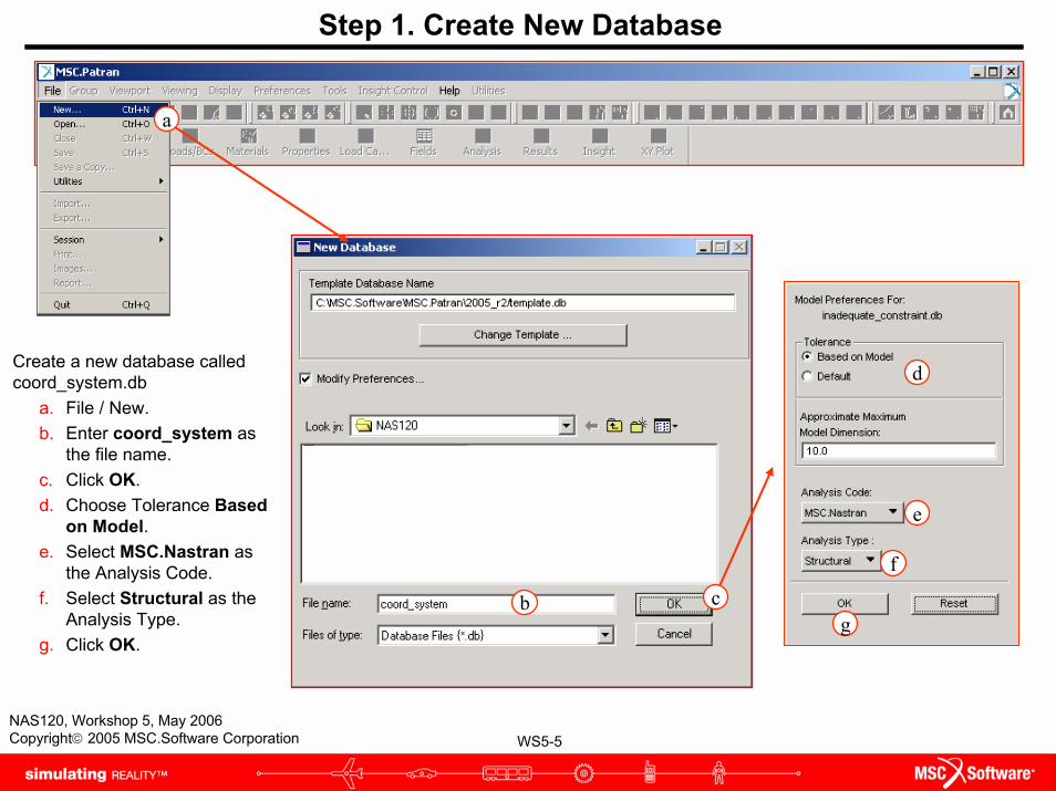
Step 1. Create New Database
Create a new database called coord_system.db
a. File / New.b. Enter coord_system as
the file name.c. Click OK.d. Choose Tolerance Based
on Model.e. Select MSC.Nastran as
the Analysis Code.f. Select Structural as the
Analysis Type. g. Click OK.
a
e
WS5-6NAS120, Workshop 5, May 2006Copyright© 2005 MSC.Software Corporation
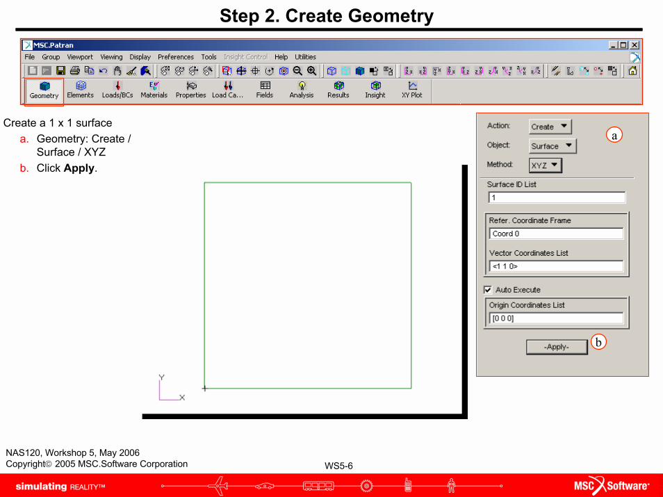
Step 2. Create Geometry
Create a 1 x 1 surfacea. Geometry: Create /
Surface / XYZb. Click Apply.
a
b
WS5-7NAS120, Workshop 5, May 2006Copyright© 2005 MSC.Software Corporation
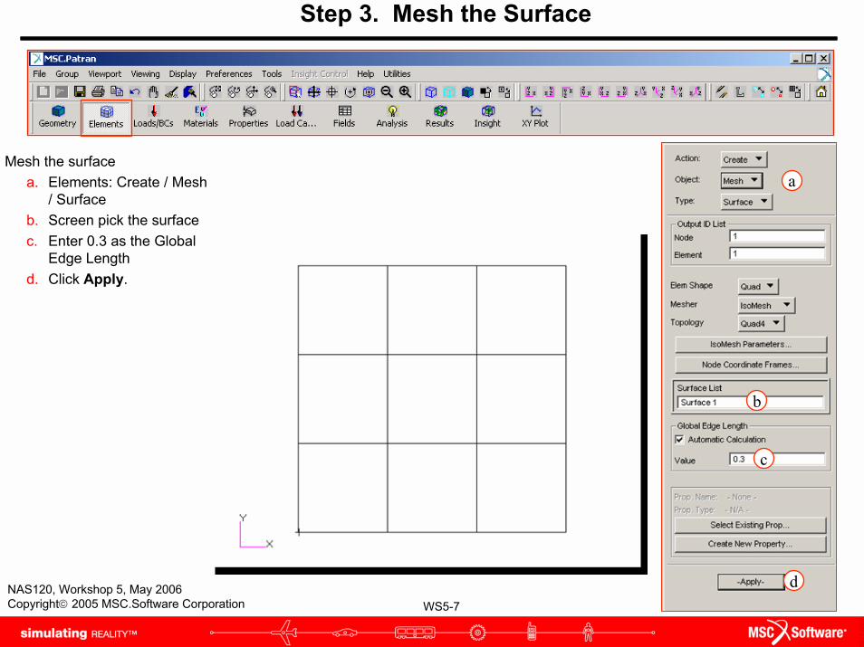
Step 3. Mesh the Surface
Mesh the surfacea. Elements: Create / Mesh
/ Surfaceb. Screen pick the surfacec. Enter 0.3 as the Global
Edge Lengthd. Click Apply.
a
b
c
d
WS5-8NAS120, Workshop 5, May 2006Copyright© 2005 MSC.Software Corporation
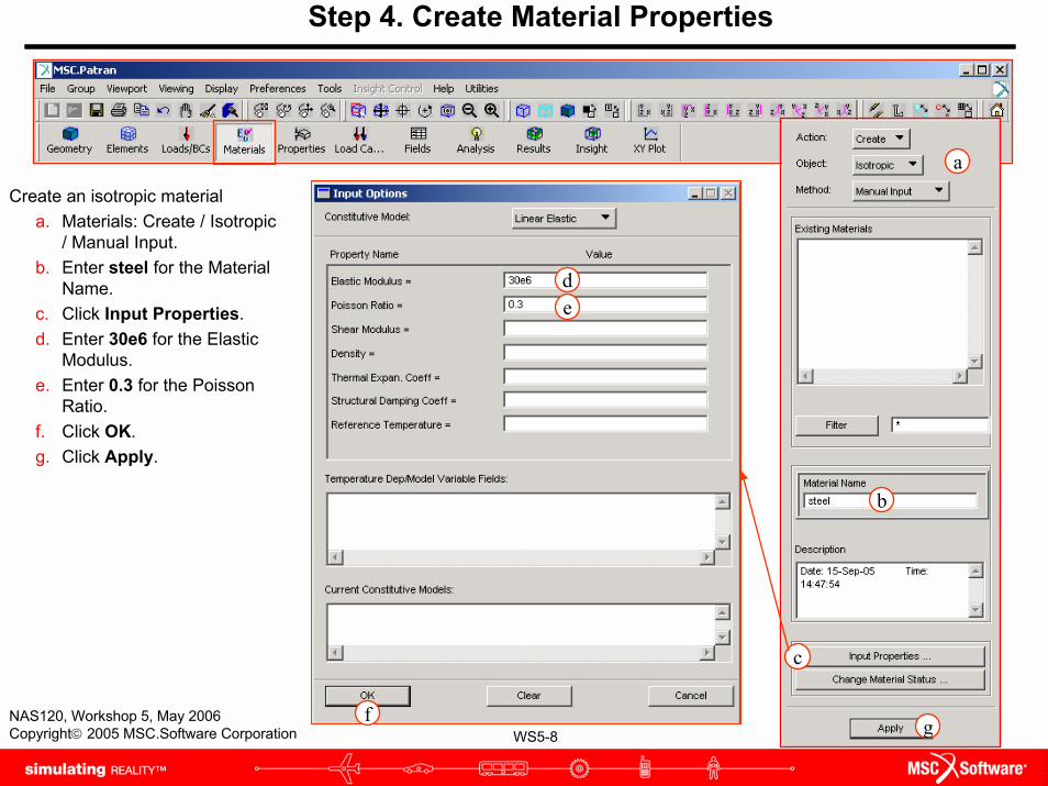
Step 4. Create Material Properties
Create an isotropic materiala. Materials: Create / Isotropic
/ Manual Input.b. Enter steel for the Material
Name.c. Click Input Properties.d. Enter 30e6 for the Elastic
Modulus.e. Enter 0.3 for the Poisson
Ratio.f. Click OK. g. Click Apply.
d
f
e
a
c
b
g
WS5-9NAS120, Workshop 5, May 2006Copyright© 2005 MSC.Software Corporation
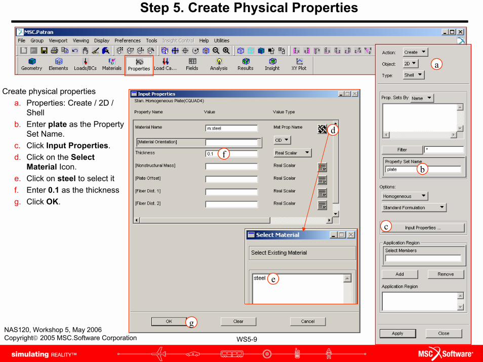
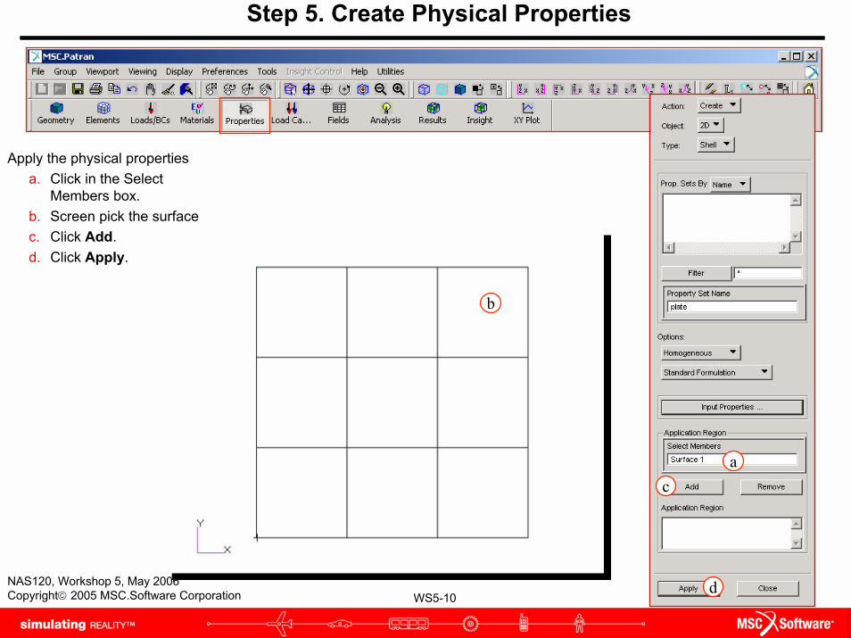
Step 5. Create Physical Properties
Create physical propertiesa. Properties: Create / 2D /
Shellb. Enter plate as the Property
Set Name.c. Click Input Properties.d. Click on the Select
Material Icon.e. Click on steel to select itf. Enter 0.1 as the thicknessg. Click OK.
d
f
e
g
a
b
c
WS5-10NAS120, Workshop 5, May 2006Copyright© 2005 MSC.Software Corporation
Apply the physical propertiesa. Click in the Select
Members box.b. Screen pick the surfacec. Click Add.d. Click Apply.
Step 5. Create Physical Properties
b
ac
d
WS5-11NAS120, Workshop 5, May 2006Copyright© 2005 MSC.Software Corporation
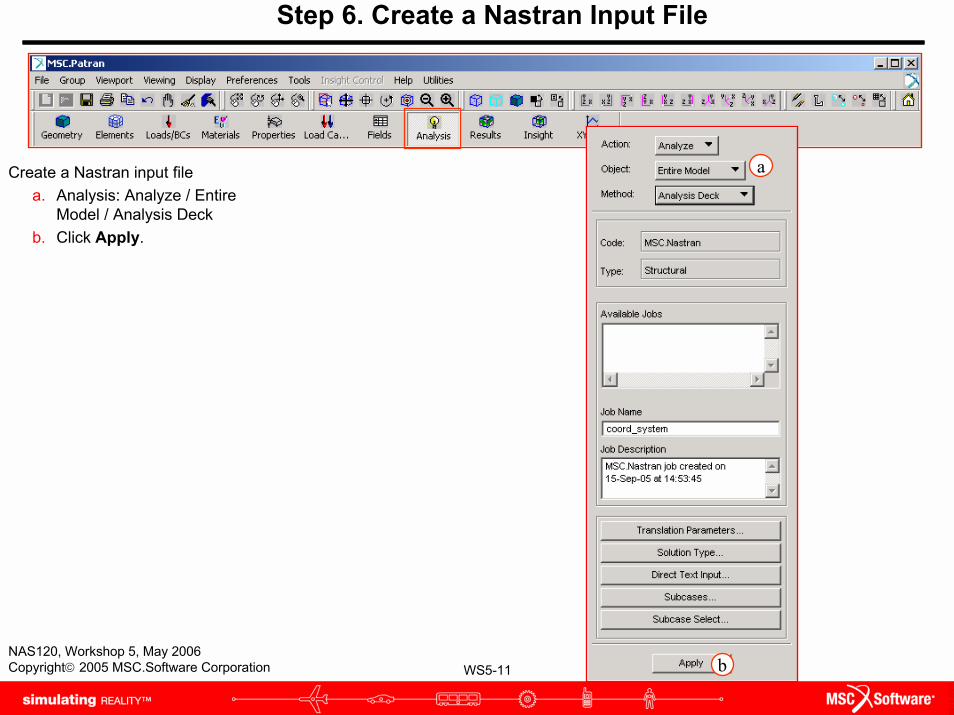
Step 6. Create a Nastran Input File
Create a Nastran input filea. Analysis: Analyze / Entire
Model / Analysis Deckb. Click Apply.
a
b
WS5-12NAS120, Workshop 5, May 2006Copyright© 2005 MSC.Software Corporation
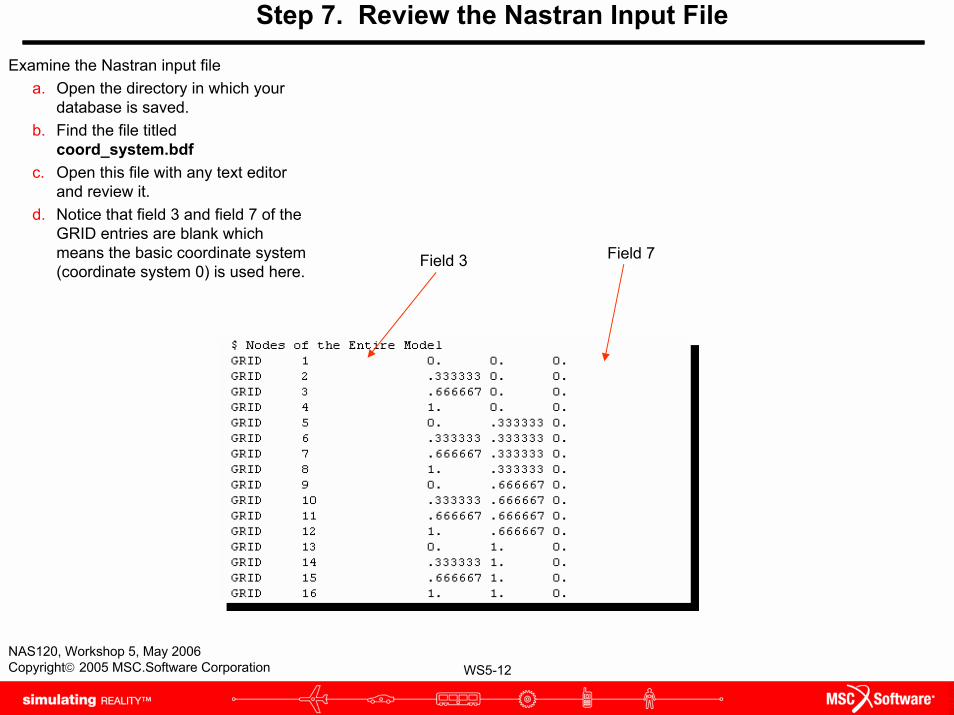
Step 7. Review the Nastran Input File
Examine the Nastran input filea. Open the directory in which your
database is saved.b. Find the file titled
coord_system.bdfc. Open this file with any text editor
and review it.d. Notice that field 3 and field 7 of the
GRID entries are blank which means the basic coordinate system (coordinate system 0) is used here.
Field 3 Field 7
WS5-13NAS120, Workshop 5, May 2006Copyright© 2005 MSC.Software Corporation
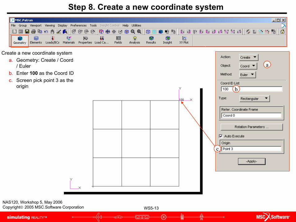
Step 8. Create a new coordinate system
Create a new coordinate systema. Geometry: Create / Coord
/ Eulerb. Enter 100 as the Coord IDc. Screen pick point 3 as the
origin
a
b
c
WS5-14NAS120, Workshop 5, May 2006Copyright© 2005 MSC.Software Corporation
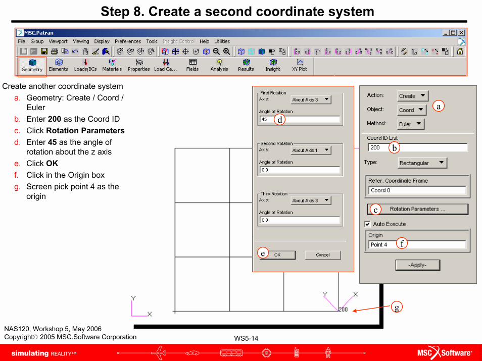
Step 8. Create a second coordinate system
Create another coordinate systema. Geometry: Create / Coord /
Eulerb. Enter 200 as the Coord IDc. Click Rotation Parametersd. Enter 45 as the angle of
rotation about the z axise. Click OKf. Click in the Origin boxg. Screen pick point 4 as the
origin
a
b
c
d
ef
g
WS5-15NAS120, Workshop 5, May 2006Copyright© 2005 MSC.Software Corporation
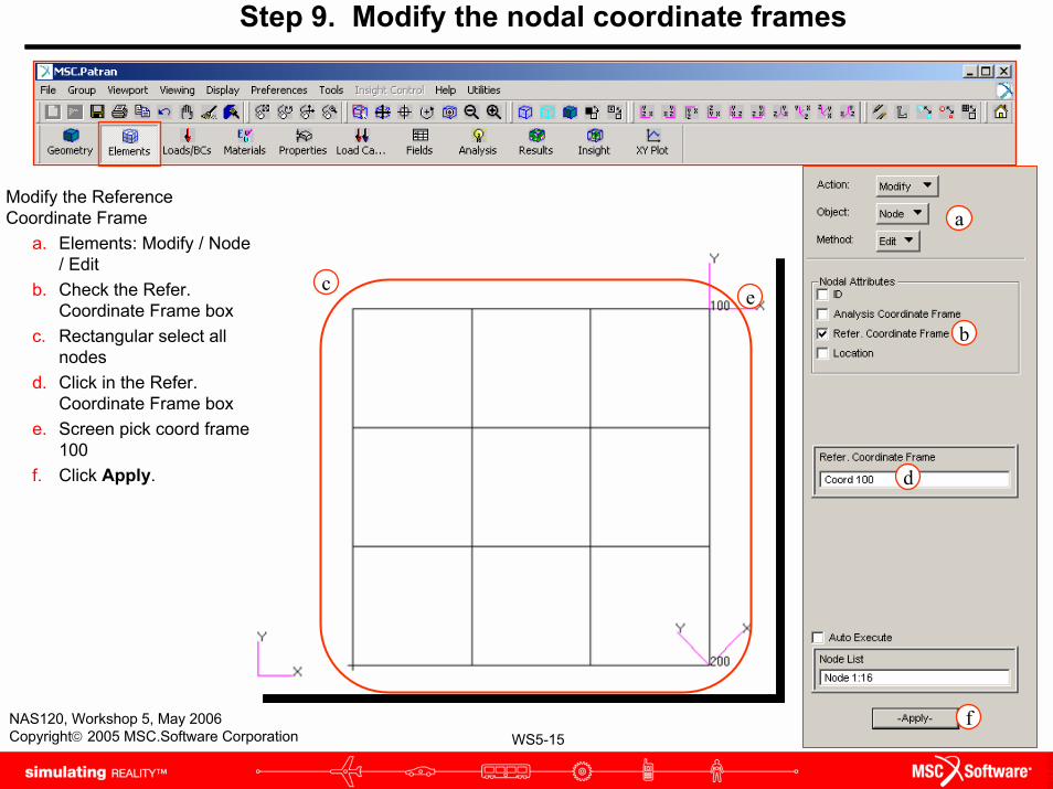
Step 9. Modify the nodal coordinate frames
Modify the Reference Coordinate Frame
a. Elements: Modify / Node / Edit
b. Check the Refer. Coordinate Frame box
c. Rectangular select all nodes
d. Click in the Refer. Coordinate Frame box
e. Screen pick coord frame 100
f. Click Apply.
a
b
c
d
e
f
WS5-16NAS120, Workshop 5, May 2006Copyright© 2005 MSC.Software Corporation
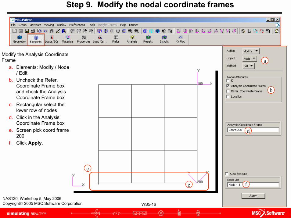
Step 9. Modify the nodal coordinate frames
Modify the Analysis Coordinate Frame
a. Elements: Modify / Node / Edit
b. Uncheck the Refer. Coordinate Frame box and check the Analysis Coordinate Frame box
c. Rectangular select the lower row of nodes
d. Click in the Analysis Coordinate Frame box
e. Screen pick coord frame 200
f. Click Apply.
a
b
c
d
e f
WS5-17NAS120, Workshop 5, May 2006Copyright© 2005 MSC.Software Corporation
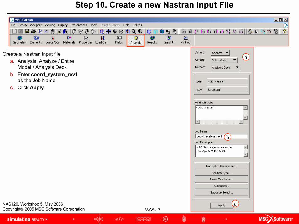
Step 10. Create a new Nastran Input File
Create a Nastran input filea. Analysis: Analyze / Entire
Model / Analysis Deckb. Enter coord_system_rev1
as the Job Namec. Click Apply.
a
b
c
WS5-18NAS120, Workshop 5, May 2006Copyright© 2005 MSC.Software Corporation
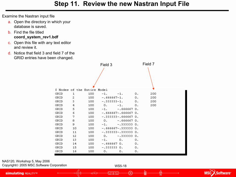
Step 11. Review the new Nastran Input File
Examine the Nastran input filea. Open the directory in which your
database is saved.b. Find the file titled
coord_system_rev1.bdfc. Open this file with any text editor
and review it.d. Notice that field 3 and field 7 of the
GRID entries have been changed.
Field 3 Field 7


![CFX Intro 12.0 WS5 Centrifugal Pump[1]](https://img.pdfslide.us/doc/110x75/551247264a7959e5028b48e1/cfx-intro-120-ws5-centrifugal-pump1.jpg)