Embed Size (px)
Citation preview
WS1 - 1
Composites Technology Day, February 2012
Copyright 2012 MSC.Software Corporation
WORKSHOP 1
Composite Wing
WS1 - 2
Composites Technology Day, February 2012
Copyright 2012 MSC.Software Corporation
WS1 - 3
Composites Technology Day, February 2012
Copyright 2012 MSC.Software Corporation
• Workshop Objectives
– Become familiar with the basic steps in doing a composites analysis
• Software Version
– Patran 2011
– MD Nastran 2011.1
• Required File:
– composite_wing.db
WS1 - 4
Composites Technology Day, February 2012
Copyright 2012 MSC.Software Corporation
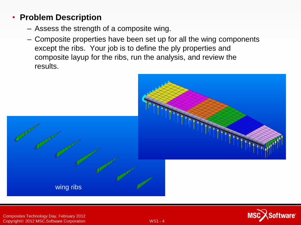
• Problem Description
– Assess the strength of a composite wing.
– Composite properties have been set up for all the wing components
except the ribs. Your job is to define the ply properties and
composite layup for the ribs, run the analysis, and review the
results.
wing ribs
WS1 - 5
Composites Technology Day, February 2012
Copyright 2012 MSC.Software Corporation
a
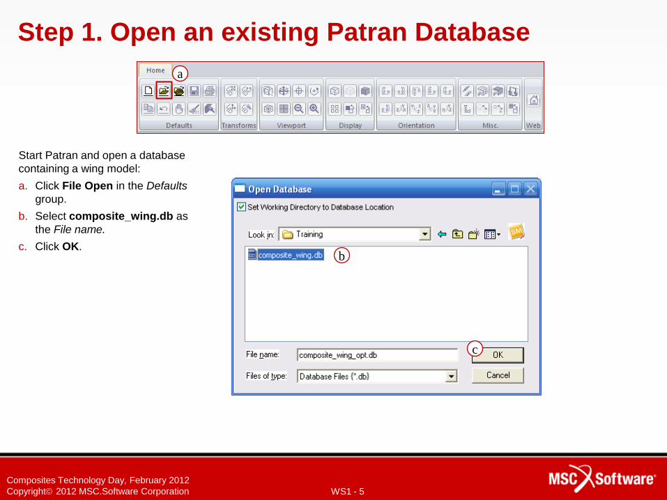
Step 1. Open an existing Patran Database
Start Patran and open a database
containing a wing model:
a. Click File Open in the Defaults
group.
b. Select composite_wing.db as
the File name.
c. Click OK.
c
b
WS1 - 6
Composites Technology Day, February 2012
Copyright 2012 MSC.Software Corporation
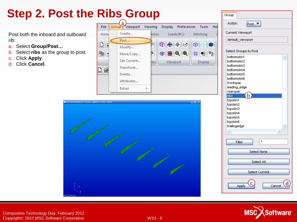
Step 2. Post the Ribs Group
Post both the inboard and outboard
rib:
a. Select Group/Post…
b. Select ribs as the group to post.
c. Click Apply.
d. Click Cancel.
a
b
c d
WS1 - 7
Composites Technology Day, February 2012
Copyright 2012 MSC.Software Corporation
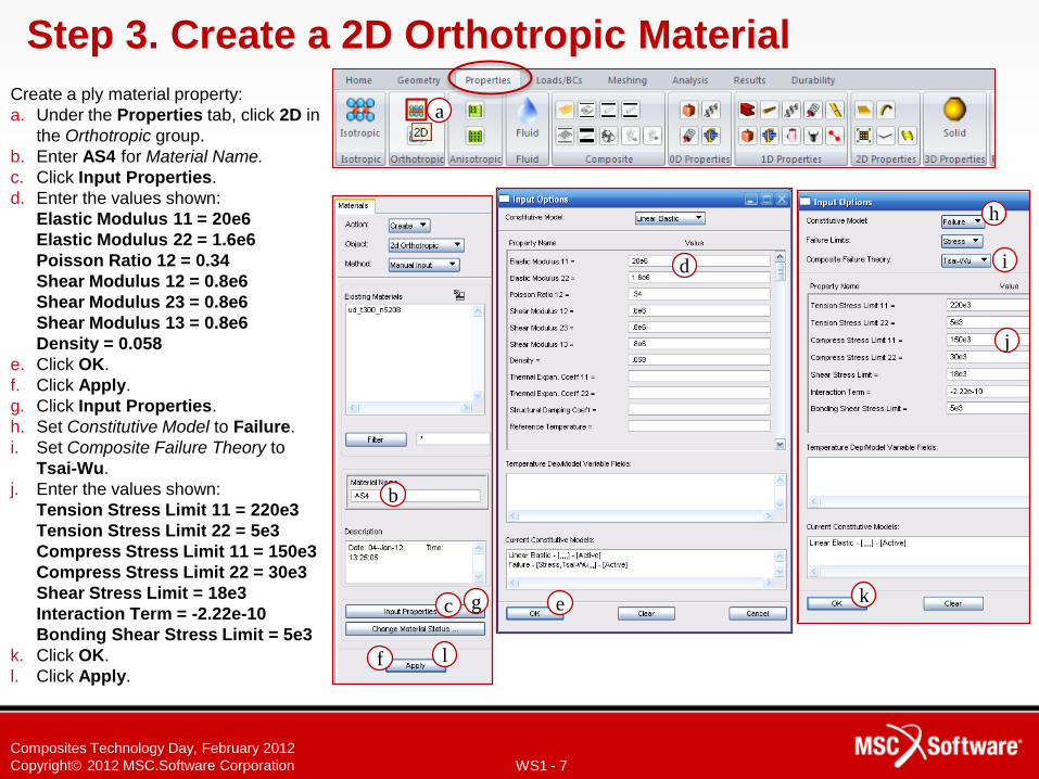
Step 3. Create a 2D Orthotropic Material
Create a ply material property:
a. Under the Properties tab, click 2D in
the Orthotropic group.
b. Enter AS4 for Material Name.
c. Click Input Properties.
d. Enter the values shown:
Elastic Modulus 11 = 20e6
Elastic Modulus 22 = 1.6e6
Poisson Ratio 12 = 0.34
Shear Modulus 12 = 0.8e6
Shear Modulus 23 = 0.8e6
Shear Modulus 13 = 0.8e6
Density = 0.058
e. Click OK.
f. Click Apply.
g. Click Input Properties.
h. Set Constitutive Model to Failure.
i. Set Composite Failure Theory to
Tsai-Wu.
j. Enter the values shown:
Tension Stress Limit 11 = 220e3
Tension Stress Limit 22 = 5e3
Compress Stress Limit 11 = 150e3
Compress Stress Limit 22 = 30e3
Shear Stress Limit = 18e3
Interaction Term = -2.22e-10
Bonding Shear Stress Limit = 5e3
k. Click OK.
l. Click Apply.
b
d
c
h
i
k
l
j
e g
f
a
WS1 - 8
Composites Technology Day, February 2012
Copyright 2012 MSC.Software Corporation
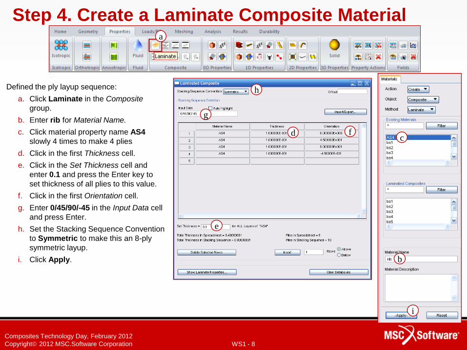
Step 4. Create a Laminate Composite Material
Defined the ply layup sequence:
a. Click Laminate in the Composite
group.
b. Enter rib for Material Name.
c. Click material property name AS4
slowly 4 times to make 4 plies
d. Click in the first Thickness cell.
e. Click in the Set Thickness cell and
enter 0.1 and press the Enter key to
set thickness of all plies to this value.
f. Click in the first Orientation cell.
g. Enter 0/45/90/-45 in the Input Data cell
and press Enter.
h. Set the Stacking Sequence Convention
to Symmetric to make this an 8-ply
symmetric layup.
i. Click Apply.
a
c
h
g
i
e
d f
b
WS1 - 9
Composites Technology Day, February 2012
Copyright 2012 MSC.Software Corporation
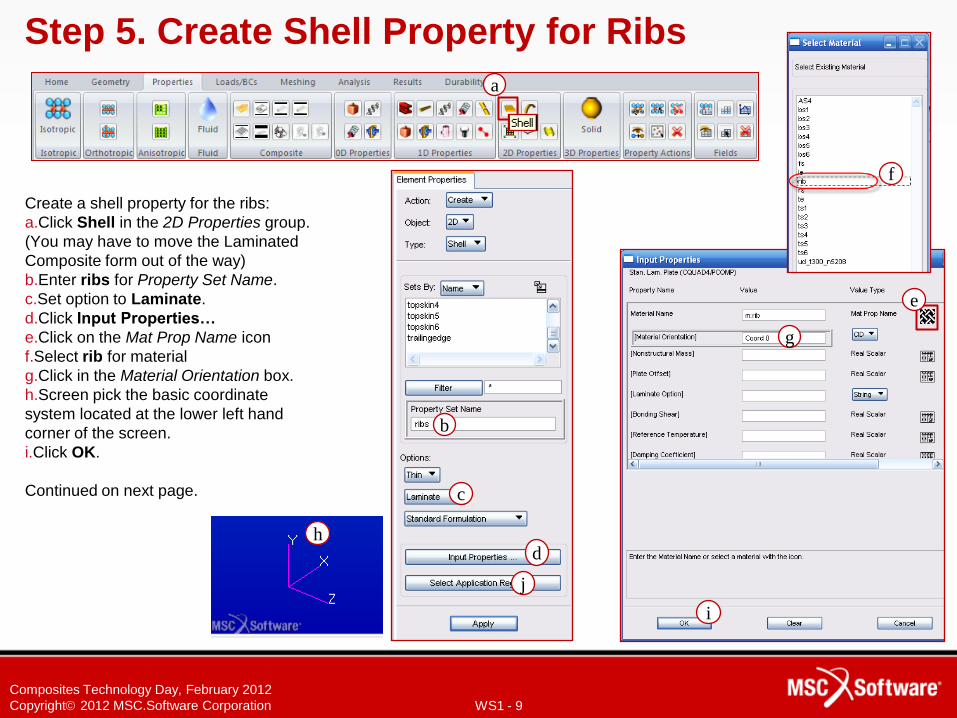
Create a shell property for the ribs:
a.Click Shell in the 2D Properties group.
(You may have to move the Laminated
Composite form out of the way)
b.Enter ribs for Property Set Name.
c.Set option to Laminate.
d.Click Input Properties…
e.Click on the Mat Prop Name icon
f.Select rib for material
g.Click in the Material Orientation box.
h.Screen pick the basic coordinate
system located at the lower left hand
corner of the screen.
i.Click OK.
Continued on next page.
Step 5. Create Shell Property for Ribs
g
c
b
d
e
f
a
f
i
j
h
WS1 - 10
Composites Technology Day, February 2012
Copyright 2012 MSC.Software Corporation
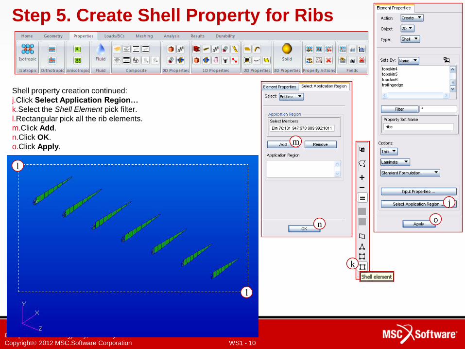
Shell property creation continued:
j.Click Select Application Region…
k.Select the Shell Element pick filter.
l.Rectangular pick all the rib elements.
m.Click Add.
n.Click OK.
o.Click Apply.
Step 5. Create Shell Property for Ribs
k
j
l
l
m
n o
WS1 - 11
Composites Technology Day, February 2012
Copyright 2012 MSC.Software Corporation
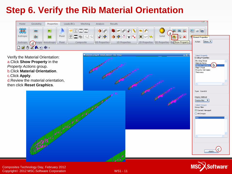
Step 6. Verify the Rib Material Orientation
Verify the Material Orientation:
a.Click Show Property in the
Property Actions group.
b.Click Material Orientation.
c.Click Apply.
d.Review the material orientation,
then click Reset Graphics.
b
c
d
a
WS1 - 12
Composites Technology Day, February 2012
Copyright 2012 MSC.Software Corporation
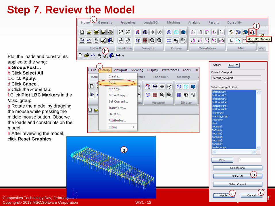
Step 7. Review the Model
Plot the loads and constraints
applied to the wing:
a.Group/Post…
b.Click Select All
c.Click Apply.
d.Click Cancel.
e.Click the Home tab.
f.Click Plot LBC Markers in the
Misc. group.
g.Rotate the model by dragging
the mouse while pressing the
middle mouse button. Observe
the loads and constraints on the
model.
h.After reviewing the model,
click Reset Graphics.
a
b
c d
e
f
h
g
WS1 - 13
Composites Technology Day, February 2012
Copyright 2012 MSC.Software Corporation
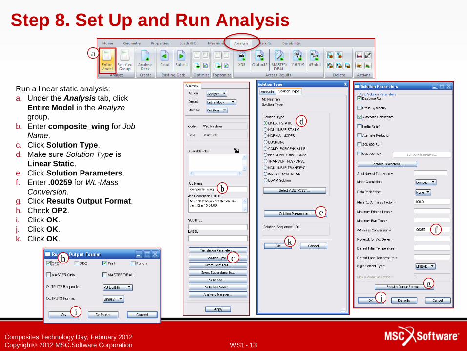
Step 8. Set Up and Run Analysis
Run a linear static analysis:
a. Under the Analysis tab, click
Entire Model in the Analyze
group.
b. Enter composite_wing for Job
Name.
c. Click Solution Type.
d. Make sure Solution Type is
Linear Static.
e. Click Solution Parameters.
f. Enter .00259 for Wt.-Mass
Conversion.
g. Click Results Output Format.
h. Check OP2.
i. Click OK.
j. Click OK.
k. Click OK.
a
b
c
d
e
g
h
i
j
k
f
WS1 - 14
Composites Technology Day, February 2012
Copyright 2012 MSC.Software Corporation
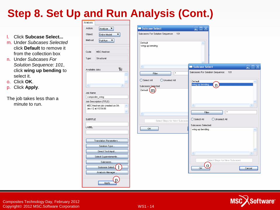
Step 8. Set Up and Run Analysis (Cont.)
l. Click Subcase Select...
m. Under Subcases Selected
click Default to remove it
from the collection box
n. Under Subcases For
Solution Sequence: 101,
click wing up bending to
select it.
o. Click OK.
p. Click Apply.
The job takes less than a
minute to run.
l
m
p
n
o
WS1 - 15
Composites Technology Day, February 2012
Copyright 2012 MSC.Software Corporation
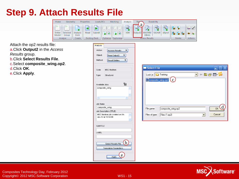
Step 9. Attach Results File
Attach the op2 results file:
a.Click Output2 in the Access
Results group.
b.Click Select Results File.
c.Select composite_wing.op2.
d.Click OK.
e.Click Apply.
a
b
c
d
e
WS1 - 16
Composites Technology Day, February 2012
Copyright 2012 MSC.Software Corporation
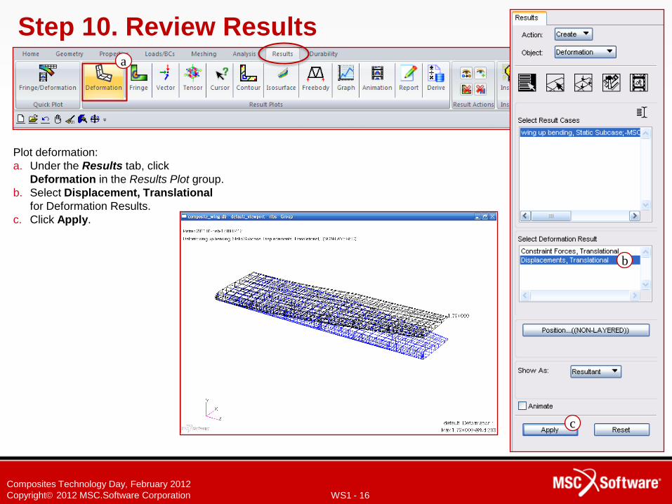
Step 10. Review Results
Plot deformation:
a. Under the Results tab, click
Deformation in the Results Plot group.
b. Select Displacement, Translational
for Deformation Results.
c. Click Apply.
a
c
b
WS1 - 17
Composites Technology Day, February 2012
Copyright 2012 MSC.Software Corporation
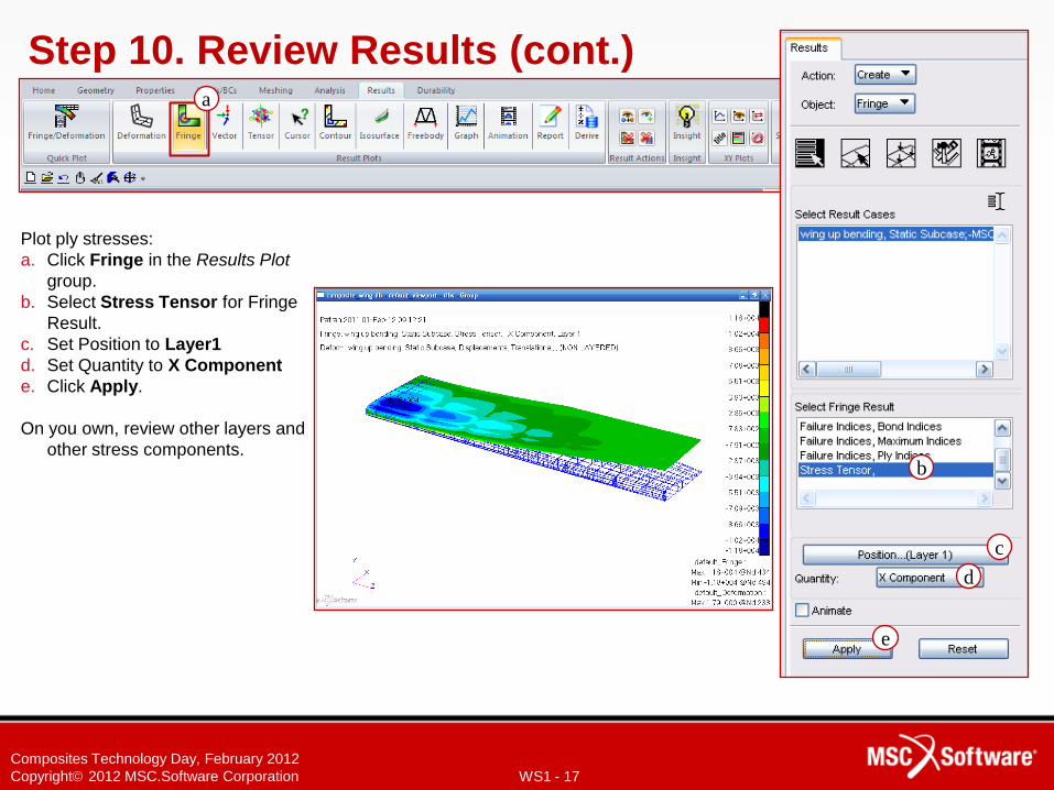
Step 10. Review Results (cont.)
Plot ply stresses:
a. Click Fringe in the Results Plot
group.
b. Select Stress Tensor for Fringe
Result.
c. Set Position to Layer1
d. Set Quantity to X Component
e. Click Apply.
On you own, review other layers and
other stress components.
a
c
b
d
e
WS1 - 18
Composites Technology Day, February 2012
Copyright 2012 MSC.Software Corporation
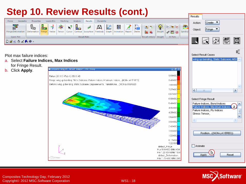
Step 10. Review Results (cont.)
Plot max failure indices:
a. Select Failure Indices, Max Indices
for Fringe Result.
b. Click Apply.
a
b
WS1 - 19
Composites Technology Day, February 2012
Copyright 2012 MSC.Software Corporation
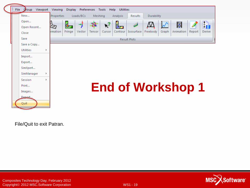
End of Workshop 1
File/Quit to exit Patran.