Embed Size (px)
Citation preview
Workflow Partitioning and Deployment on the Cloud using Orchestra
Ward Jaradat, Alan Dearle, and Adam BarkerSchool of Computer Science, University of St Andrews, North Haugh, St Andrews, Fife, KY16 9SX, United Kingdom
{ward.jaradat, alan.dearle, adam.barker}@st-andrews.ac.uk
Abstract—Orchestrating service-oriented workflows is typi-cally based on a design model that routes both data and controlthrough a single point – the centralised workflow engine. Thiscauses scalability problems that include the unnecessary con-sumption of the network bandwidth, high latency in transmit-ting data between the services, and performance bottlenecks.These problems are highly prominent when orchestratingworkflows that are composed from services dispersed acrossdistant geographical locations. This paper presents a novelworkflow partitioning approach, which attempts to improvethe scalability of orchestrating large-scale workflows. It permitsthe workflow computation to be moved towards the servicesproviding the data in order to garner optimal performanceresults. This is achieved by decomposing the workflow intosmaller sub workflows for parallel execution, and determiningthe most appropriate network locations to which these subworkflows are transmitted and subsequently executed. Thispaper demonstrates the efficiency of our approach using a setof experimental workflows that are orchestrated over AmazonEC2 and across several geographic network regions.
Keywords-Service-oriented workflows, orchestration, parti-tioning, computation placement analysis, deployment
I. INTRODUCTION
Service workflows represent the automation of servicesduring which data is passed between the services forprocessing. Typically, workflows are orchestrated based ona centralised design model that provides control over theworkflow, supports process automation, and encapsulatesthe workflow logic in a central location at which itsexecution takes place. There are several languages used todescribe service workflows such as the Business ProcessExecution Language (BPEL) [1], which has been acceptedas a standard service orchestration language. The SimpleConceptual Unified Flow Language (SCUFL) is an exampleof a language for specifying large-scale workflows suchas those seen in scientific applications [2]. It is supportedby the Taverna workbench and is typically executed usinga workflow engine known as Freefluo [3]. However,workflow management systems of this kind route bothdata and control through a single point, which causesscaling problems including the unnecessary consumptionof network bandwidth, high latency in transmitting databetween the services, and performance bottlenecks.
Scientific workflows can be composed from services thatmay be dispersed across distant geographical locations.Determining the most appropriate location at which to
execute the workflow logic becomes difficult as thenumber of geographically distributed services increases.Most workflow management approaches rely on dataplacement strategies that attempt to move the data closerto locations at which the computation takes place [4], [5],[6], [7], [8]. This involves a set of activities related to datatransfer, staging, replication, management and allocationof resources. However, the distribution of large portionsof data between the services and across long distancesthrough the centralised engine can affect the data transferrate, increase the execution time, risk overwhelming thestorage resources at execution sites, and degrade theoverall workflow performance. Recent research efforts showinterest in using Infrastructure as a Service (IaaS) cloudsthat provide on-demand computational services to supportcost-efficient workflow management [9], [10], but do notexamine how the geographical location of services canaffect the workflow performance.
The principal contribution of this paper is a partitioningapproach that permits a workflow to be decomposed intosmaller sub workflows for parallel execution on the cloud.It determines the most appropriate locations to which thesesub workflows are transmitted and subsequently executed.Unlike existing approaches that depend on data placement,our approach permits the workflow computation to bemoved closer to the services providing the data. Throughadopting this approach, distributed workflow engines cancollaborate together to execute the overall workflow. Eachengine is carefully selected to execute a smaller part of theworkflow within short network distance to the services. Forinstance, an engine may be selected if it is hosted in thesame network region where the services are resident in acloud-based environment. Our approach relies on collectingQuality of Service (QoS) information that represents thenetwork delay (e.g. network latency and bandwidth) witha combination of heuristics to select the nearest enginesto the services. It is hypothesised that this improves theworkflow performance by reducing the overall data transferamong the services.
Previously we created a distributed architecture forexecuting service workflows [11], which relies on a high-level language [12] for specifying workflows. However,the published articles relating to these works do not
discuss our workflow partitioning approach. This paperpresents a refined design of our architecture, evaluates ourapproach accordingly, and compares it to existing works.In order to investigate the benefits of our approach, weuse a set of experimental workflows that are executedover Amazon EC2 and across several geographic networkregions. These workflows are based on dataflow patternsthat are commonly used to compose large-scale scientificworkflows [13], which include the pipeline, distribution andaggregation patterns.
The rest of this paper is organised as follows: Section IIpresents a simple workflow example that is used throughoutthe paper to explain our approach. Section III presentsour workflow partitioning approach. Section IV discussesa workflow partitioning example. Section V discusses andevaluates our approach implementation. Section VI reviewsrelated works. Finally, section VII summarises our workachievements and states future research directions.
II. WORKFLOW EXAMPLE
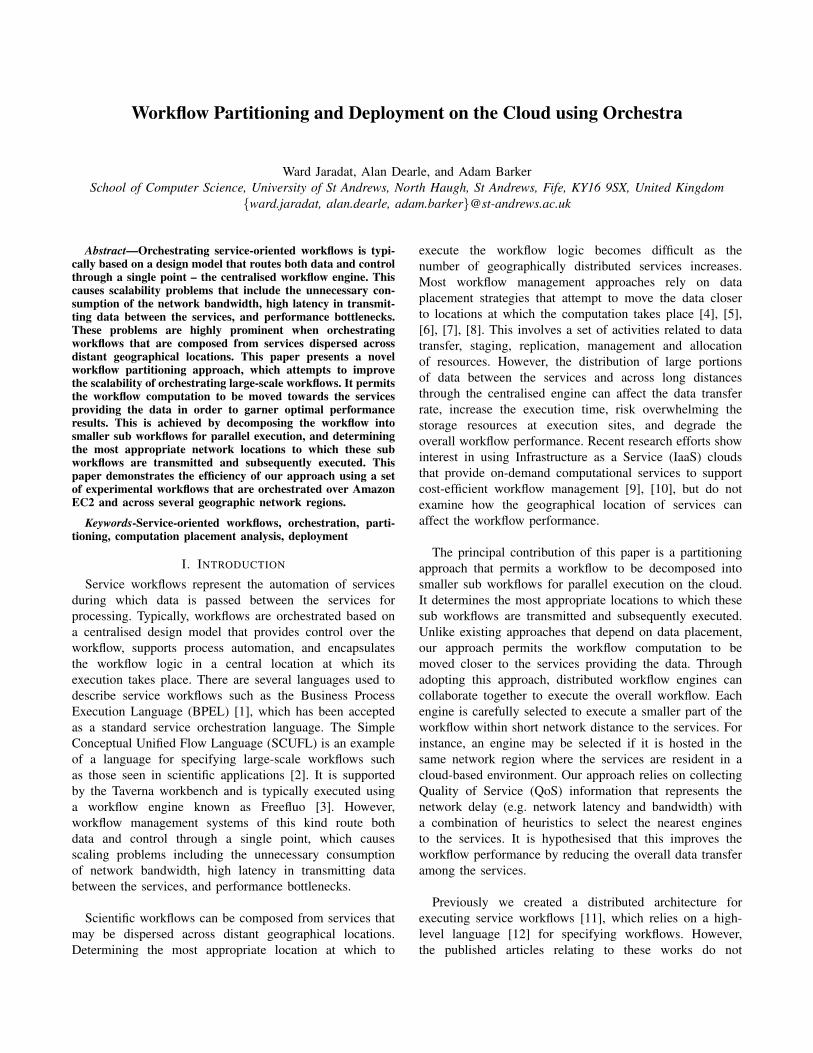
Our approach relies on a new high-level functional datacoordination language for the specification of workflowsknown as Orchestra. It separates the workflow logic from itsexecution, and permits a workflow architect (e.g. scientist,engineer) to design a workflow without knowledge of howit is executed. Orchestra allows a workflow to be composedas a Directed Acyclic Graph (DAG) that supports commondataflow patterns, and provides succinct abstractions fordefining the services and coordinating the dataflow betweenthem. This section provides a simple workflow example thatis used throughout this paper to explain our approach. Figure1 shows its structure, where the input a is used to invokeservice S1, which produces an output that is used to invokeS2 whose output is then passed to S3. The output of S3 isused to invoke both S4 and S5, whose outputs are used asinputs for S6, which produces the final workflow output x.
a
S1 S2 S3
S4
S5
S6
x
Data Service
Figure 1: A Directed Acyclic Graph (DAG) workflow.
Listing 1 presents the specification of this workflowusing our language where the workflow name example
is defined in line 1 using the workflow keyword. Thedescription keyword is used to declare identifiers for aservice description documents, each of which can be located
using a URL through lines 2-7. This permits the compilerto retrieve information about the services, their operationsand associated types for syntax analysis. The servicekeyword is used to declare the service identifiers s1, s2,s3, s4, s5 and s6 through lines 8-13. Similarly, the serviceports p1, p2, p3, p4, p5 and p6 are declared using theport keyword through lines 14-19. The input and outputkeywords define the workflow interface, which provides aninput a and an output x of the same type through lines 20-23.
01 workflow example02 description d1 is http://ward.host.cs.st-
andrews.ac.uk/documents/service1.wsdl..07 description d6 is http://ward.host.cs.st-
andrews.ac.uk/documents/service6.wsdl08 service s1 is d1.Service1..13 service s6 is d6.Service614 port p1 is s1.Port1..19 port p6 is s6.Port620 input:21 int a22 output:23 int x24 a -> p1.Op125 p1.Op1 -> p2.Op226 p2.Op2 -> p3.Op327 p3.Op3 -> p4.Op4, p5.Op528 p4.Op4 -> p6.Op6.par129 p5.Op5 -> p6.Op6.par230 p6.Op6 -> x
Listing 1: Specification of the workflow in figure 1.
Our language supports common dataflow patterns byspecifying service invocations and the data passed to them.Each service invocation consists of a port identifier and anassociated operation separated by a dot symbol. The outputof a particular service invocation can be associated with anidentifier, or passed directly to another service invocation tocreate a service composition. The arrow symbol indicates thedirection of the data to or retrieved from service invocations.The following dataflow patterns are specified in listing 1:
• Pipeline pattern: This pattern is used for chainingseveral services together, where the output of a par-ticular service is used as an input to invoke another.For instance, a is used to invoke p1.Op1 whose resultis passed directly to p2.Op2, which in turn produces aresult that is passed to p3.Op3 through lines 24-26.
• Data distribution pattern: This pattern is used totransmit several identical copies of a particular serviceoutput to multiple services. For instance, the invocationresult of p3.Op3 is used to invoke both p4.Op4 andp5.Op5 in line 27. This finite sequence of invocationsis the simplest parallel data structure in our languagewhere each invocation is executed concurrently.
• Data aggregation pattern: The results of several ser-vice invocations may be passed as individual input pa-rameters to one particular service using this pattern. Forinstance, the results of both p4.Op4 and p5.Op5 areused as input parameters par1 and par2 respectively toinvoke operation p6.Op6 through lines 28-29. Finally,x represents the result of p6.Op6 in line 30.
III. OVERVIEW OF APPROACH
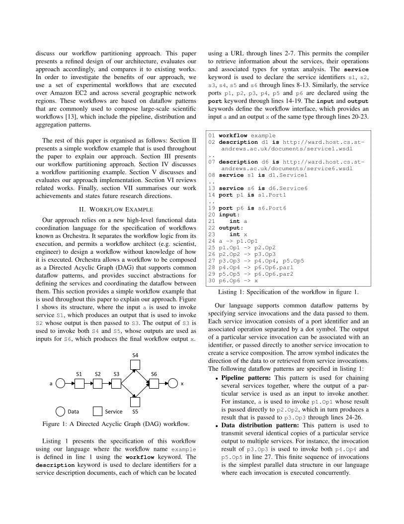
In order to realise our approach we created a fully dis-tributed orchestration architecture. Unlike existing orches-tration technology where the locus of control is representedby a centralised engine that holds the decision logic of theworkflow, the notion of a single locus of control does notexist in our architecture. During the workflow execution,the decision logic can be found at one or several engines.Figure 2 shows an overview of our architecture that consistsof distributed workflow engines. These engines collaboratetogether to complete the workflow execution. For instance,a workflow engine may be responsible for analysing andpartitioning a workflow specification into smaller sub work-flows. These sub workflows may be deployed onto remoteengines for execution. Each engine then exploits connectiv-ity to a group of services by invoking them or composingthem together, retrieving invocation results, and forwardingrelevant information to remote engines as necessary. Thefollowing sections discuss the compilation and partitioningof a workflow specification, deployment of sub workflowsand monitoring their execution.
A. CompilationOur approach uses a recursive descent compiler that
analyses a workflow specification to ensure its correctness.It does not generate machine code representation from theworkflow specification, but constructs an executable graph-based data structure instead, which consists of vertices thatrepresent service invocations with edges between them asdata dependencies. The components of this data structurecan be distributed to remote workflow engines at arbitrarynetwork locations. This permits a workflow to be maintainedupon its distribution such that it can be refactored foroptimisation purposes during run-time.
B. PartitioningOur workflow partitioning approach consists of several
phases that include workflow decomposition, placementanalysis, and composition of sub workflows.
1) Decomposition of a workflow: This phase decomposesa workflow graph into smaller data structures that representsub workflows. Hence, we created a traverser that exploresthe workflow graph to gain insight about its complexityand detect its intricate parallel parts. It obtains informationabout the workflow inputs, outputs, services, invocations,and associated types. This information is used to detectthe maximum number of smallest sub workflows, each ofwhich consists of a single invocation, or multiple sequentialinvocations to the same service if a data dependency existsbetween them.
Deployment
E1
Clo
ud
Reg
ion
(R
1)
ServicesServices
Serv
ices E2
Workflow Specification and Initial Inputs
S1 S3
S4
S5
S2
E3 S6
Clo
ud
Regio
n (R
2)
Clo
ud
Regio
n (R
3)
Information Flow
Info
rmatio
n Flo
w
Information Flow
Deployment
Final Outputs
Engine Service
Figure 2: Overview of our distributed service orchestration architecture, and the interactions between distributed workflowengines. This diagram shows an arbitrary placement of services within cloud regions based on the example in figure 1.
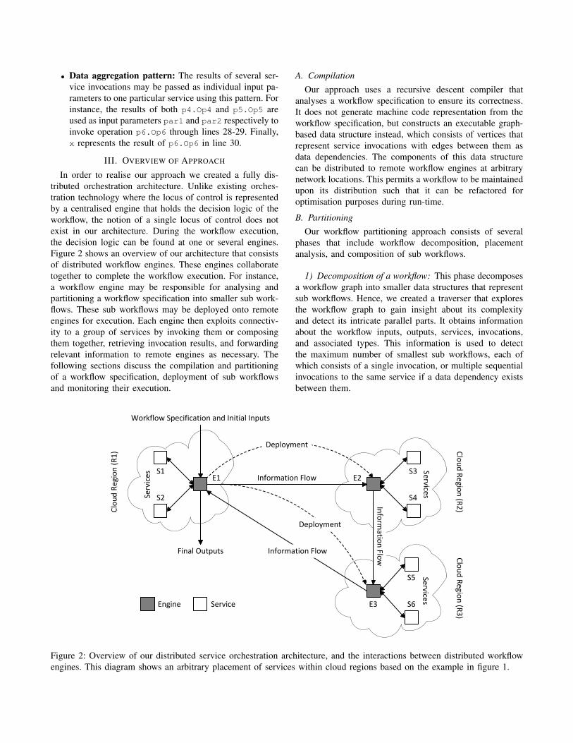
2) Placement analysis: Once a workflow has been de-composed by the traverser, placement analysis are performedto determine the most appropriate engines that may executethe sub workflows. This phase involves the following activ-ities, which are illustrated in figure 3.
• Discovery and clustering of engines: This activityidentifies a set of available engines that may execute thesub workflows1. For each sub workflow, these enginesare organised into groups using the k-means clusteringalgorithm, and according to QoS metrics that representthe network delay, which include the network latencyand bandwidth between each engine and the singleservice endpoint in the sub workflow.
• Elimination of inappropriate engines: Upon clus-tering, groups containing inappropriate engines areeliminated from further analysis. This is achieved byidentifying the engines with metrics that are worse thanthose of engines in other groups.
• Ranking and selection of engines: Each remainingcandidate engine is ranked by predicting the transmis-sion time between the engine and the service endpointusing:
T = Le−s + Sinput/Be−s (1)
where T is the transmission time, Le−s and Be−s arethe latency and bandwidth between the engine and theservice respectively, and Sinput is the size of the inputthat is used to invoke the service. Consequently, anengine with the shortest transmission time is selected.
Latency
Bandwidth
Engine
(a) Discovery
Latency
Ban
dw
idth
Group A
Group B
Engine
(b) Clustering
Latency
Ban
dw
idth
Candidate Engines
Engine
(c) Elimination
Latency
Ban
dw
idth
High Ranking Engine
Engine Selected Engine
(d) Ranking and Selection
Figure 3: Placement analysis.
1This paper does not focus on mechanisms to discover the engines.
3) Composition of sub workflows: The sub workflowsmay be combined together if the same engine is selectedto execute them. This involves introducing directed edgesbetween them wherever a data dependency exists. Conse-quently, the composite workflows are encoded using thesame language as used to specify the entire workflow. Duringthe recoding, relevant information such as the workflowinputs, outputs, service invocations, data dependencies andtype representations are all captured, and associated with thecomposite workflows to make each a self contained stand-alone workflow specification.
C. Deployment and Monitoring
Our approach uses the knowledge about the networkcondition with a combination of heuristics for initiallydeploying the workflow. Each composite workflow specifi-cation is dispatched to a designated engine, which compilesand executes it immediately. This deployment process istransparent and does not require any user intervention. Upondeployment, real-time distributed monitoring may be usedto guide the workflow toward optimal performance. Thisis achieved by detecting the network condition periodicallyand performing further placement analysis. Our approachuses the application layer capabilities to deliver useful in-formation about the network condition in terms of networklatency and bandwidth. For instance, an engine measures thelatency by computing the average round-trip time of a seriesof HTTP HEAD requests issued to a service. Similarly, thebandwidth is measured using the request completion timeand the response message size.
IV. WORKFLOW PARTITIONING EXAMPLE
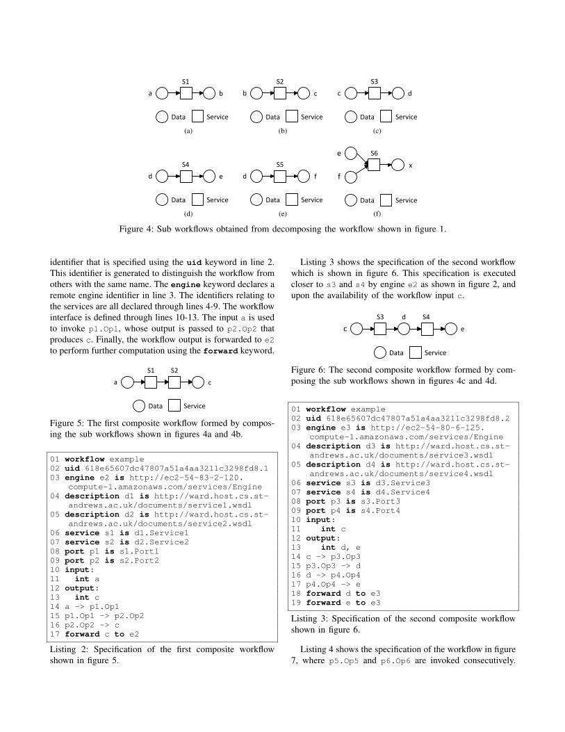
This section presents an arbitrary workflow partitioningscenario based on the workflow example in figure 1, wherethe workflow is decomposed into smaller sub workflowsas shown in figure 4. Each sub workflow consists of asingle service invocation, which requires one or moreinputs and produces a single output. Upon selectingappropriate engines to execute the sub workflows, theymay be combined together to form composite workflows.During their composition, they are analysed to detect anyexternal dependency between them where an output of a subworkflow is required as an input for another. Upon detectingan external dependency, it is replaced by a direct servicecomposition between the service endpoint that producesthe data and the one that requires it in the compositeworkflow. The intermediate data between the services maybe represented in the composite workflow as output datawhen it is required for executing other composite workflows.
Listing 2 shows a computer generated specification of thecomposite workflow shown in figure 5. This specification isexecuted by an engine that is deployed closer to services S1and S2 as shown in figure 2. It shows a universally unique
a b
S1
Data Service
(a)
b c
S2
Data Service
(b)
c d
S3
Data Service
(c)
d e
S4
Data Service
(d)
d f
S5
Data Service
(e)
Data Service
e
x
S6
f
(f)
Figure 4: Sub workflows obtained from decomposing the workflow shown in figure 1.
identifier that is specified using the uid keyword in line 2.This identifier is generated to distinguish the workflow fromothers with the same name. The engine keyword declares aremote engine identifier in line 3. The identifiers relating tothe services are all declared through lines 4-9. The workflowinterface is defined through lines 10-13. The input a is usedto invoke p1.Op1, whose output is passed to p2.Op2 thatproduces c. Finally, the workflow output is forwarded to e2
to perform further computation using the forward keyword.
a
S1
c
S2
Data Service
Figure 5: The first composite workflow formed by compos-ing the sub workflows shown in figures 4a and 4b.
01 workflow example02 uid 618e65607dc47807a51a4aa3211c3298fd8.103 engine e2 is http://ec2-54-83-2-120.
compute-1.amazonaws.com/services/Engine04 description d1 is http://ward.host.cs.st-
andrews.ac.uk/documents/service1.wsdl05 description d2 is http://ward.host.cs.st-
andrews.ac.uk/documents/service2.wsdl06 service s1 is d1.Service107 service s2 is d2.Service208 port p1 is s1.Port109 port p2 is s2.Port210 input:11 int a12 output:13 int c14 a -> p1.Op115 p1.Op1 -> p2.Op216 p2.Op2 -> c17 forward c to e2
Listing 2: Specification of the first composite workflowshown in figure 5.
Listing 3 shows the specification of the second workflowwhich is shown in figure 6. This specification is executedcloser to s3 and s4 by engine e2 as shown in figure 2, andupon the availability of the workflow input c.
c
dS3
e
S4
Data Service
Figure 6: The second composite workflow formed by com-posing the sub workflows shown in figures 4c and 4d.
01 workflow example02 uid 618e65607dc47807a51a4aa3211c3298fd8.203 engine e3 is http://ec2-54-80-6-125.
compute-1.amazonaws.com/services/Engine04 description d3 is http://ward.host.cs.st-
andrews.ac.uk/documents/service3.wsdl05 description d4 is http://ward.host.cs.st-
andrews.ac.uk/documents/service4.wsdl06 service s3 is d3.Service307 service s4 is d4.Service408 port p3 is s3.Port309 port p4 is s4.Port410 input:11 int c12 output:13 int d, e14 c -> p3.Op315 p3.Op3 -> d16 d -> p4.Op417 p4.Op4 -> e18 forward d to e319 forward e to e3
Listing 3: Specification of the second composite workflowshown in figure 6.
Listing 4 shows the specification of the workflow in figure7, where p5.Op5 and p6.Op6 are invoked consecutively.
Finally, the workflow output x is forwarded to engine e1,which acts as a data sink for the workflow outputs. Typically,this engine is the initial engine that partitioned the workflowand deployed it.
d
S5
S6
x
e
Data Service
Figure 7: The third composite workflow formed by compos-ing the sub workflows shown in figures 4e and 4f.
01 workflow example02 uid 618e65607dc47807a51a4aa3211c3298fd8.303 engine e1 is http://ec2-54-80-3-122.
compute-1.amazonaws.com/services/Engine04 description d5 is http://ward.host.cs.st-
andrews.ac.uk/documents/service5.wsdl05 description d6 is http://ward.host.cs.st-
andrews.ac.uk/documents/service6.wsdl06 service s5 is d5.Service507 service s6 is d6.Service608 port p5 is s5.Port509 port p6 is s6.Port610 input:11 int d, e12 output:13 int x14 d -> p5.Op515 p5.Op5 -> p6.Op6.par216 e -> p6.Op6.par117 p6.Op6 -> x18 forward x to e1
Listing 4: Specification of the third composite workflowshown in figure 7.
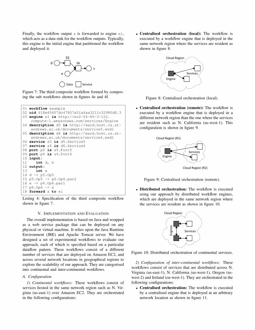
V. IMPLEMENTATION AND EVALUATION
The overall implementation is based on Java and wrappedas a web service package that can be deployed on anyphysical or virtual machine. It relies upon the Java RuntimeEnvironment (JRE) and Apache Tomcat server. We havedesigned a set of experimental workflows to evaluate ourapproach, each of which is specified based on a particulardataflow pattern. These workflows consist of a differentnumber of services that are deployed on Amazon EC2, andacross several network locations in geographical regions toexplore the scalability of our approach. They are categorisedinto continental and inter-continental workflows.
A. Configuration1) Continental workflows: These workflows consist of
services hosted in the same network region such as N. Vir-ginia (us-east-1) over Amazon EC2. They are orchestratedin the following configurations:
• Centralised orchestration (local): The workflow isexecuted by a workflow engine that is deployed in thesame network region where the services are resident asshown in figure 8.
Engine
Services
Cloud Region
Figure 8: Centralised orchestration (local).
• Centralised orchestration (remote): The workflow isexecuted by a workflow engine that is deployed in adifferent network region than the one where the servicesare resident such as N. California (us-west-1). Thisconfiguration is shown in figure 9.
Engine
Services
Cloud Region (R1)
Cloud Region (R2)
Figure 9: Centralised orchestration (remote).
• Distributed orchestration: The workflow is executedusing our approach by distributed workflow engines,which are deployed in the same network region wherethe services are resident as shown in figure 10.
Engi
nes
Services
Cloud Region
Figure 10: Distributed orchestration of continental services.
2) Configuration of inter-continental workflows: Theseworkflows consist of services that are distributed across N.Virginia (us-east-1), N. California (us-west-1), Oregon (us-west-2) and Ireland (eu-west-1). They are orchestrated in thefollowing configurations:
• Centralised orchestration: The workflow is executedby a centralised engine that is deployed at an arbitrarynetwork location as shown in figure 11.
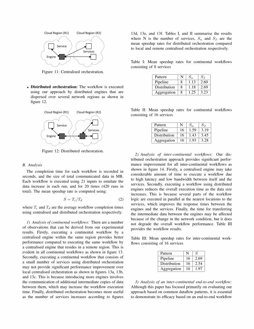
Engine
Services
Cloud Region (R1) Cloud Region (R2)
Service
Figure 11: Centralised orchestration.
• Distributed orchestration: The workflow is executedusing our approach by distributed engines that aredispersed over several network regions as shown infigure 12.
Engine
Services
Cloud Region (R1) Cloud Region (R2)
Service
Figure 12: Distributed orchestration.
B. Analysis
The completion time for each workflow is recorded inseconds, and the size of total communicated data in MB.Each workflow is executed using 21 inputs to emulate thedata increase in each run, and for 20 times (420 runs intotal). The mean speedup rate is computed using:
S = Tc/Td (2)
where Tc and Td are the average workflow completion timesusing centralised and distributed orchestration respectively.
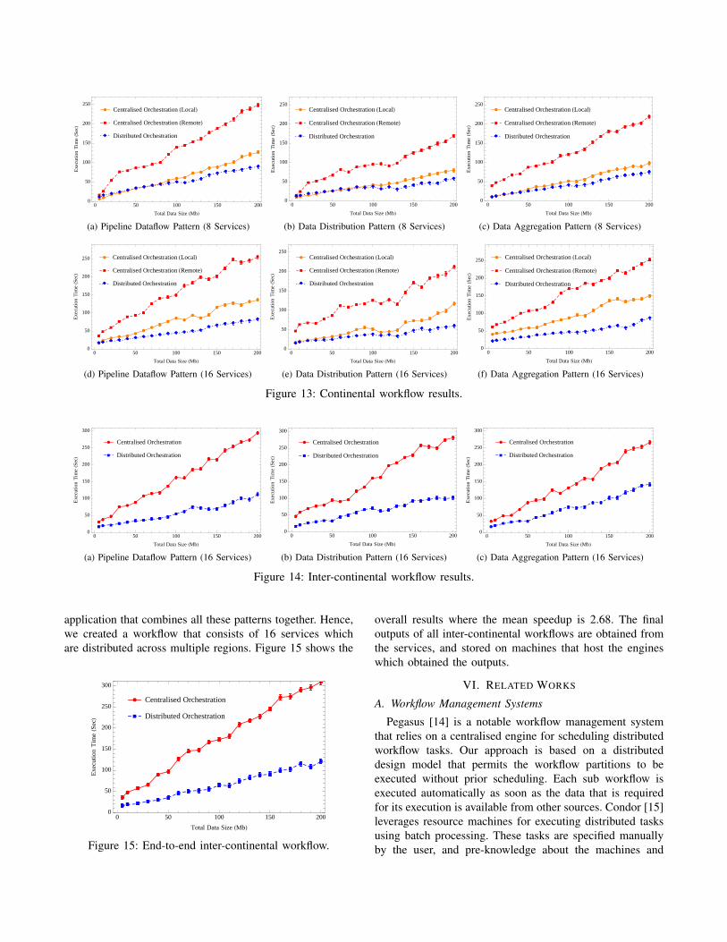
1) Analysis of continental workflows: There are a numberof observations that can be derived from our experimentalresults. Firstly, executing a continental workflow by acentralised engine within the same region provides betterperformance compared to executing the same workflow bya centralised engine that resides in a remote region. This isevident in all continental workflows as shown in figure 13.Secondly, executing a continental workflow that consists ofa small number of services using distributed orchestrationmay not provide significant performance improvement overlocal centralised orchestration as shown in figures 13a, 13b,and 13c. This is because introducing more engines involvesthe communication of additional intermediate copies of databetween them, which may increase the workflow executiontime. Finally, distributed orchestration becomes more usefulas the number of services increases according to figures
13d, 13e, and 13f. Tables I, and II summarise the resultswhere N is the number of services, Sα and Sβ are themean speedup rates for distributed orchestration comparedto local and remote centralised orchestration respectively.
Table I: Mean speedup rates for continental workflowsconsisting of 8 services
Pattern N Sα SβPipeline 8 1.13 2.60Distribution 8 1.18 2.69Aggregation 8 1.25 3.23
Table II: Mean speedup rates for continental workflowsconsisting of 16 services
Pattern N Sα SβPipeline 16 1.59 3.19Distribution 16 1.43 3.45Aggregation 16 1.93 3.28
2) Analysis of inter-continental workflows: Our dis-tributed orchestration approach provides significant perfor-mance improvement for all inter-continental workflows asshown in figure 14. Firstly, a centralised engine may takeconsiderable amount of time to execute a workflow dueto high latency and low bandwidth between itself and theservices. Secondly, executing a workflow using distributedengines reduces the overall execution time as the data sizeincreases. This is because several parts of the workflowlogic are executed in parallel at the nearest locations to theservices, which improves the response times between theengines and the services. Finally, the time for transferringthe intermediate data between the engines may be affectedbecause of the change in the network condition, but it doesnot degrade the overall workflow performance. Table IIIprovides the workflow results.
Table III: Mean speedup rates for inter-continental work-flows consisting of 16 services
Pattern N SPipeline 16 2.69Distribution 16 2.54Aggregation 16 1.97
3) Analysis of an inter-continental end-to-end workflow:Although this paper has focused primarily on evaluating ourapproach based on common dataflow patterns, it is essentialto demonstrate its efficacy based on an end-to-end workflow
æ ææ
ææ
ææ
ææ
ææ æ
æ æ
æ ææ
æ
ææ
æ
à
à
à
à àà à
àà
à
àà
àà
à
à
à
à
àà
à
ìì ì ì
ìì ì ì ì ì ì ì
ìì
ì ì ì ì ìì ì
æ Centralised Orchestration HLocalLà Centralised Orchestration HRemoteLì Distributed Orchestration
0 50 100 150 2000
50
100
150
200
250
Total Data Size HMbL
Exec
uti
on
Tim
eHS
ecL
(a) Pipeline Dataflow Pattern (8 Services)
æ æ æ ææ æ æ
æ æ ææ æ
æ ææ æ
ææ æ
æ æ
àà
àà
àà
àà
à àà à
àà
àà
àà
àà
à
ììì ì ì ì
ì ìì ì ì
ìì
ìì ì
ì ì ìì ì
æ Centralised Orchestration HLocalLà Centralised Orchestration HRemoteLì Distributed Orchestration
0 50 100 150 2000
50
100
150
200
250
Total Data Size HMbL
Exec
uti
on
Tim
eHS
ecL
(b) Data Distribution Pattern (8 Services)
æ æ æ ææ
ææ æ æ
æ æ ææ
ææ
ææ æ
æ ææ
àà
à
à à
à àà
à
à àà
à
à
à
à à
àà
à
à
ììì ì ì ì ì ì
ì ì ì ì ì ìì ì
ì ì ì ì ì
æ Centralised Orchestration HLocalLà Centralised Orchestration HRemoteLì Distributed Orchestration
0 50 100 150 2000
50
100
150
200
250
Total Data Size HMbL
Exec
uti
on
Tim
eHS
ecL
(c) Data Aggregation Pattern (8 Services)
ææ
æ æ ææ
ææ
ææ
ææ
ææ
æ
ææ
ææ
ææ
à
à
à
à
àà
à
à
à àà
àà
àà
à
à
àà
àà
ìì ì ì ì ì ì ì ì ì ì ì ì ìì ì ì ì
ì ì ì
æ Centralised Orchestration HLocalLà Centralised Orchestration HRemoteLì Distributed Orchestration
0 50 100 150 2000
50
100
150
200
250
Total Data Size HMbL
Exec
uti
on
Tim
eHS
ecL
(d) Pipeline Dataflow Pattern (16 Services)
æ æ æ æ æ æ ææ
ææ
ææ æ æ
ææ æ
æ
ææ
æ
à
àà à
àà
à àà à
àà
à
à
à
à
à
àà
à
à
ìì ì ì ì ìì ì ì ì ì ì ì ì
ìì
ì ìì ì ì
æ Centralised Orchestration HLocalLà Centralised Orchestration HRemoteLì Distributed Orchestration
0 50 100 150 2000
50
100
150
200
250
Total Data Size HMbL
Exec
uti
on
Tim
eHS
ecL
(e) Data Distribution Pattern (16 Services)
æ æ æ ææ æ æ
ææ
ææ
æ æ
æ
æ
ææ
ææ æ
æ
àà
à
à
àà à
à
à
à
à à
à àà
à
àà
à
à
à
ìì ì ì ì ì ì ì ì ì ì ì ì ì ìì ì
ìì
ìì
æ Centralised Orchestration HLocalLà Centralised Orchestration HRemoteLì Distributed Orchestration
0 50 100 150 2000
50
100
150
200
250
Total Data Size HMbL
Exec
uti
on
Tim
eHS
ecL
(f) Data Aggregation Pattern (16 Services)
Figure 13: Continental workflow results.
ææ
æ
æ ææ
ææ æ
æ
æ æ
æ æ
æ æ
æ
æ
ææ
æ
à à àà à
à à à à àà
à
à à à àà
à
à à
à
æ Centralised Orchestration
à Distributed Orchestration
0 50 100 150 2000
50
100
150
200
250
300
Total Data Size HMbL
Exec
uti
on
Tim
eHS
ecL
(a) Pipeline Dataflow Pattern (16 Services)
æ
ææ
æ æ
ææ
æ
æ
æ
æ æ
ææ
ææ
æ æ æ
ææ
à àà à à à
àà
àà à
à à
à à
à àà à à à
æ Centralised Orchestration
à Distributed Orchestration
0 50 100 150 2000
50
100
150
200
250
300
Total Data Size HMbL
Exec
uti
on
Tim
eHS
ecL
(b) Data Distribution Pattern (16 Services)
æ æ
æ æ
æ
ææ æ
ææ
æ
æ
æ æ
æ
æ æ
ææ
æ
æ
à àà à à à
àà
àà
à à à
à à
à à
àà
à à
æ Centralised Orchestration
à Distributed Orchestration
0 50 100 150 2000
50
100
150
200
250
300
Total Data Size HMbL
Exec
uti
on
Tim
eHS
ecL
(c) Data Aggregation Pattern (16 Services)
Figure 14: Inter-continental workflow results.
application that combines all these patterns together. Hence,we created a workflow that consists of 16 services whichare distributed across multiple regions. Figure 15 shows the
æ
ææ
æ
ææ
æ
æ æ
ææ
æ
ææ
æ
æ
æ æ
ææ
æ
à à àà à
àà à à à
à à
àà
à àà à
àà
à
æ Centralised Orchestration
à Distributed Orchestration
0 50 100 150 2000
50
100
150
200
250
300
Total Data Size HMbL
Exec
uti
on
Tim
eHS
ecL
Figure 15: End-to-end inter-continental workflow.
overall results where the mean speedup is 2.68. The finaloutputs of all inter-continental workflows are obtained fromthe services, and stored on machines that host the engineswhich obtained the outputs.
VI. RELATED WORKS
A. Workflow Management Systems
Pegasus [14] is a notable workflow management systemthat relies on a centralised engine for scheduling distributedworkflow tasks. Our approach is based on a distributeddesign model that permits the workflow partitions to beexecuted without prior scheduling. Each sub workflow isexecuted automatically as soon as the data that is requiredfor its execution is available from other sources. Condor [15]leverages resource machines for executing distributed tasksusing batch processing. These tasks are specified manuallyby the user, and pre-knowledge about the machines and
the condition of the network is required. Our architecturehandles the partitioning and mapping of workflows onto ma-chines automatically by collecting information about the net-work condition, and performing placement analysis. Triana[16] permits a workflow to be distributed across machines,and supports control flows by associating coordination logicwith workflow scripts. Control flows are unnecessary inour approach as it is relies on a dataflow language thatavoids loops and control structures in the workflow. Kepler[17] is based on actor-oriented modelling that permits aworkflow to be composed using actors which communicatethrough well-defined interfaces. However, it does not supportdecentralised execution of workflows.
B. Dataflow Optimisation Architectures
The Circulate approach [18], [19] supports data distribu-tion in the workflow using proxy components, which may bedeployed closer to the services. These proxies exploit con-nectivity to the services, and route the data in the workflowto locations where they are required. However, this architec-ture relies on a centralised flow mechanism to facilitate thecollaboration between proxies, and there seems to be no au-tomated mechanism for partitioning the workflow. The Flow-based Infrastructure for Composing Autonomous Services(FICAS) [20] supports service composition by altering theservice interfaces to enable peer-to-peer collaboration. Ourapproach does not require modifying the implementation ofservices. Data processing techniques built on MapReduce[21] may be suitable for a wide range of problems, butare inadequate for executing workflows. For instance, aworkflow can be composed using a series of MapReducejobs [22], but this requires passing the entire state anddata from one job to the next which degrades performance.Dryad [23] supports executing distributed processing tasks,but it does not provide any mechanism to rearrange theworkflow structure for optimisation purposes. Furthermore,the distributed workflow parts must be specified manually.Our approach automatically generates the distributed subworkflow specifications.
C. Workflow Scheduling Approaches
There are many scheduling heuristics that attempt tosolve the workflow mapping problem such as HEFT [24],Min-Min [25], MaxMin and MCT [26], but these worksare directed at grid-based workflow applications. Severalother heuristic methods were proposed and compared in[27]. Partitioning is proposed for provisioning resources intoexecution sites in [28] and [29], but not for decomposingthe actual dataflow graph. In [30] and [31], a strategy isdiscussed where the workflow tasks are mapped onto gridsites. This is achieved by assigning weights to the verticesand edges in the workflow graph by predicting the executiontime for each task, and the time for transferring data betweenthe resources. Each task is then mapped onto a resource that
provides the earliest expected time to complete its execution.However, the time for executing a service operation cannotbe predicted efficiently in a service-oriented environmentas it depends on the application logic, and the underlyingprotocols and infrastructure.
VII. CONCLUSION
Centralised service orchestration presents significant scal-ability problems as the number of services and the sizeof data involved in the workflow increases. These prob-lems include the unnecessary consumption of the networkbandwidth, high latency in transmitting data between theservices, and performance bottlenecks. This paper has pre-sented and evaluated a novel workflow partitioning approachthat decomposes a workflow into smaller sub workflows,which may then be transmitted to appropriate locationsat which their execution takes place. These locations arecarefully determined using a heuristic technique that relieson the knowledge of the network condition. This permits theworkflow logic to be executed within short geographical dis-tance to the services, which improves the overall workflowperformance. Future work will focus on real-time distributedmonitoring, and re-deployment of executing sub workflowsto adapt to dynamic changes in the execution environment.
REFERENCES
[1] T. Andrews, F. Curbera, H. Dholakia, Y. Goland, J. Klein,F. Leymann, K. Liu, D. Roller, D. Smith, S. Thatte, et al.,“Business process execution language for web services,”2003.
[2] G. Juve, A. L. Chervenak, E. Deelman, S. Bharathi, G. Mehta,and K. Vahi, “Characterizing and profiling scientific work-flows,” Future Generation Computer Systems, vol. 29, no. 3,pp. 682–692, 2013.
[3] T. M. Oinn, M. Addis, J. Ferris, D. Marvin, M. Senger, R. M.Greenwood, T. Carver, K. Glover, M. R. Pocock, A. Wipat,and P. Li, “Taverna: a tool for the composition and enactmentof bioinformatics workflows,” Bioinformatics, vol. 20, no. 17,pp. 3045–3054, 2004.
[4] S. Bharathi and A. Chervenak, “Data staging strategies andtheir impact on the execution of scientific workflows,” inProceedings of the Second International Workshop on Data-aware Distributed Computing, DADC ’09, (New York, NY,USA), ACM, 2009.
[5] A. L. Chervenak, E. Deelman, M. Livny, M. Su, R. Schuler,S. Bharathi, G. Mehta, and K. Vahi, “Data placement forscientific applications in distributed environments,” in 8thIEEE/ACM International Conference on Grid Computing(GRID 2007), September 19-21, 2007, Austin, Texas, USA,Proceedings, pp. 267–274, 2007.
[6] K. Ranganathan and I. T. Foster, “Simulation studies ofcomputation and data scheduling algorithms for data grids,”Journal of Grid Computing, vol. 1, no. 1, pp. 53–62, 2003.
[7] T. Kosar and M. Livny, “A framework for reliable and efficientdata placement in distributed computing systems,” Journalof Parallel and Distributed Computing, vol. 65, no. 10,pp. 1146–1157, 2005.
[8] D. Thain, J. Basney, S. Son, and M. Livny, “The kangarooapproach to data movement on the grid,” in 10th IEEEInternational Symposium on High Performance DistributedComputing (HPDC-10 2001), 7-9 August 2001, San Fran-cisco, CA, USA, pp. 325–333, 2001.
[9] E. Deelman, G. Singh, M. Livny, G. B. Berriman, andJ. Good, “The cost of doing science on the cloud: the montageexample,” in Proceedings of the ACM/IEEE Conference onHigh Performance Computing, SC 2008, November 15-21,2008, Austin, Texas, USA, p. 50, 2008.
[10] C. Hoffa, G. Mehta, T. Freeman, E. Deelman, K. Keahey,G. B. Berriman, and J. Good, “On the use of cloud computingfor scientific workflows,” in Fourth International Conferenceon e-Science, e-Science 2008, 7-12 December 2008, Indi-anapolis, IN, USA, pp. 640–645, 2008.
[11] W. Jaradat, A. Dearle, and A. Barker, “An architecture fordecentralised orchestration of web service workflows,” in WebServices (ICWS), 2013 IEEE 20th International Conferenceon, pp. 603–604, IEEE, 2013.
[12] W. Jaradat, A. Dearle, and A. Barker, “A dataflow languagefor decentralised orchestration of web service workflows,” inServices (SERVICES), 2013 IEEE Ninth World Congress on,pp. 13–20, IEEE, 2013.
[13] A. Barker and J. Van Hemert, “Scientific workflow: a sur-vey and research directions,” in Proceedings of the 7thinternational conference on Parallel processing and appliedmathematics, pp. 746–753, Springer-Verlag, 2007.
[14] E. Deelman, G. Singh, M. Su, J. Blythe, Y. Gil, C. Kesselman,G. Mehta, K. Vahi, G. B. Berriman, J. Good, A. C. Laity, J. C.Jacob, and D. S. Katz, “Pegasus: A framework for mappingcomplex scientific workflows onto distributed systems,” Sci-entific Programming, vol. 13, no. 3, pp. 219–237, 2005.
[15] M. J. Litzkow, M. Livny, and M. W. Mutka, “Condor -A hunter of idle workstations,” in Proceedings of the 8thInternational Conference on Distributed Computing Systems,San Jose, California, USA, June 13-17, 1988, pp. 104–111,1988.
[16] I. J. Taylor, M. S. Shields, I. Wang, and R. Philp, “DistributedP2P computing within triana: A galaxy visualization testcase,” in 17th International Parallel and Distributed Pro-cessing Symposium (IPDPS 2003), 22-26 April 2003, Nice,France, CD-ROM/Abstracts Proceedings, p. 16, 2003.
[17] B. Ludascher, I. Altintas, C. Berkley, D. Higgins, E. Jaeger,M. B. Jones, E. A. Lee, J. Tao, and Y. Zhao, “Scientificworkflow management and the kepler system,” Concurrencyand Computation: Practice and Experience, vol. 18, no. 10,pp. 1039–1065, 2006.
[18] A. Barker, J. B. Weissman, and J. I. van Hemert, “Reducingdata transfer in service-oriented architectures: The circulateapproach,” IEEE Transactions on Services Computing, vol. 5,no. 3, pp. 437–449, 2012.
[19] A. Barker, J. B. Weissman, and J. I. van Hemert, “TheCirculate architecture: avoiding workflow bottlenecks causedby centralised orchestration,” Cluster Computing, vol. 12,no. 2, pp. 221–235, 2009.
[20] W. D. Liu, A distributed data flow model for composingsoftware services. PhD thesis, Stanford University, 2003.
[21] J. Dean and S. Ghemawat, “Mapreduce: simplified dataprocessing on large clusters,” Communications of the ACM,vol. 51, no. 1, pp. 107–113, 2008.
[22] J. Cohen, “Graph twiddling in a mapreduce world,” Comput-ing in Science and Engineering, vol. 11, no. 4, pp. 29–41,2009.
[23] M. Isard, M. Budiu, Y. Yu, A. Birrell, and D. Fetterly, “Dryad:distributed data-parallel programs from sequential buildingblocks,” in Proceedings of the 2007 EuroSys Conference,Lisbon, Portugal, March 21-23, 2007, pp. 59–72, 2007.
[24] H. Topcuoglu, S. Hariri, and M. Wu, “Performance-effectiveand low-complexity task scheduling for heterogeneous com-puting,” IEEE Transactions on Parallel Distributed Systems,vol. 13, no. 3, pp. 260–274, 2002.
[25] J. Blythe, S. Jain, E. Deelman, Y. Gil, K. Vahi, A. Mandal,and K. Kennedy, “Task scheduling strategies for workflow-based applications in grids,” in 5th International Symposiumon Cluster Computing and the Grid (CCGrid 2005), 9-12May, 2005, Cardiff, UK, pp. 759–767, 2005.
[26] T. D. Braun, H. J. Siegel, N. Beck, L. Boloni, M. Mah-eswaran, A. I. Reuther, J. P. Robertson, M. D. Theys, B. Yao,D. A. Hensgen, and R. F. Freund, “A comparison of elevenstatic heuristics for mapping a class of independent tasks ontoheterogeneous distributed computing systems,” Journal ofParallel and Distributed Computing, vol. 61, no. 6, pp. 810–837, 2001.
[27] R. Sakellariou and H. Zhao, “A hybrid heuristic for DAGscheduling on heterogeneous systems,” in 18th InternationalParallel and Distributed Processing Symposium (IPDPS2004), CD-ROM / Abstracts Proceedings, 26-30 April 2004,Santa Fe, New Mexico, USA, 2004.
[28] S. Kumar, S. K. Das, and R. Biswas, “Graph partitioning forparallel applications in heterogeneous grid environments,” in16th International Parallel and Distributed Processing Sym-posium (IPDPS 2002), 15-19 April 2002, Fort Lauderdale,FL, USA, CD-ROM/Abstracts Proceedings, 2002.
[29] C. Lin, C. Shih, and C. Hsu, “Adaptive dynamic schedulingalgorithms for mapping ongoing m-tasks to pr2 grid,” Journalof Information Science and Engineering, vol. 26, no. 6,pp. 2107–2125, 2010.
[30] R. Duan, R. Prodan, and T. Fahringer, “Run-time optimisationof grid workflow applications,” in 7th IEEE/ACM Interna-tional Conference on Grid Computing (GRID 2006), Septem-ber 28-29, 2006, Barcelona, Spain, Proceedings, pp. 33–40,2006.
[31] M. Wieczorek, R. Prodan, and T. Fahringer, “Scheduling ofscientific workflows in the ASKALON grid environment,”SIGMOD Record, vol. 34, no. 3, pp. 56–62, 2005.


![Announcements - cs.cornell.edu · EAI - Workflow - Web Technologies • Message Brokers, EAI, Workflow • [ACKM04] Ch 3 • Web Technologies, J2EE Introduction • [ACKM04] Ch](https://img.pdfslide.us/doc/110x75/600a79c075364822293670e2/announcements-cs-eai-workiow-web-technologies-a-message-brokers-eai.jpg)