Embed Size (px)
Citation preview
Training – GHS Crane Module Creative Systems, Inc.www.ghsport.com
Table of ContentsWorking with Cranes in GHS......................................................................................................1The Main Wizard Window...........................................................................................................2Crane Setup ...............................................................................................................................3Crane Parameters Dialog............................................................................................................4Crane Drawing Wizard................................................................................................................6Testing the Geometry model.....................................................................................................10Setting Lifting Modes.................................................................................................................10Hook Capacity Table..................................................................................................................11Crane Analysis..........................................................................................................................15
Working with Cranes in GHSWhen a load is suspended by a crane, the weight is considered as acting downward from a point on the crane that supports the cable. The BOOM command is available to simplify locating the coordinates of the boom end, allowing input of azimuth & elevation rather than L,T,V. By entering parameters based on the crane's geometry (boom length, topping angle, swing angle, etc.), GHS will determine the location of the support load in the model's coordinate system. This location is reported in the status weight output.
With macros and run files, the BOOM command can analyze multiple lifting scenarios. In addition, the BOOM command can also be used to account for the effects of counterweights, boom weight and other crane mounted weights.
Since cranes, geometrical and structural arrangements vary greatly, the use of the BOOM command can get complicated. The Crane Module is available to assist the user in setting upand analyzing complex and multiple cranes, this wizard can be found under the menu: Wizard> Conditions... > CRANE. Note: The Crane Module must be part of your GHS system to use this module. If desired you can add a shortcut key or macro to your GHS.LF load file. See the General Training Guide for additional details.
The CRANE wizard provides many advanced features to help analyze crane operations. It simplifies data entry for the BOOM command to calculate the effects of the crane load, boom, jib, counterweight, etc. Other loads, typically not considered by the Boom command, such as the weight of the rope and multiple blocks can be included. In addition, its provides the ability to set up a synchronized Condition Graphic view that will display the crane geometry respecting the current crane position.
To add to the functionality of Load Editor, hook load capacity tables can be defined. With these tables, the standard crane load displayed in Load Editor can include warnings if either the load or the list (sometimes called cross) angle are close to or exceed an allowable limit. Options to select include:
1
Training – GHS Crane Module Creative Systems, Inc.www.ghsport.com
• Predefined stability criteria• Define lifting modes• Set a stow mode which when in use, the boom weight is treated as a distributed weight• Set options for a Crane Operator's Output Table (COOT) • Define a lifting beam if present
The weight effect of the lifting beam is automatically removed from its stowed location and added to the crane load when in use.
As with most wizards, it is good practice to be in a working folder dedicated to the job at hand.The reason for this, is that files are created and saved by the wizard, some without warning. To return all the previous values, the wizard uses these files, again sometimes without warning if present in the working folder.. If you use a single folder for multiple crane analyses,previous data will be overwritten.
The Main Wizard Window
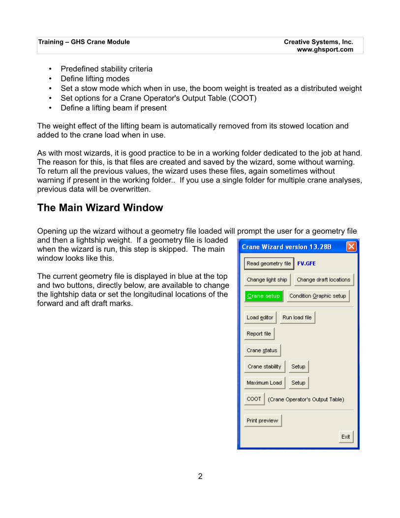
Opening up the wizard without a geometry file loaded will prompt the user for a geometry file and then a lightship weight. If a geometry file is loadedwhen the wizard is run, this step is skipped. The mainwindow looks like this.
The current geometry file is displayed in blue at the topand two buttons, directly below, are available to changethe lightship data or set the longitudinal locations of theforward and aft draft marks.
2
Training – GHS Crane Module Creative Systems, Inc.www.ghsport.com
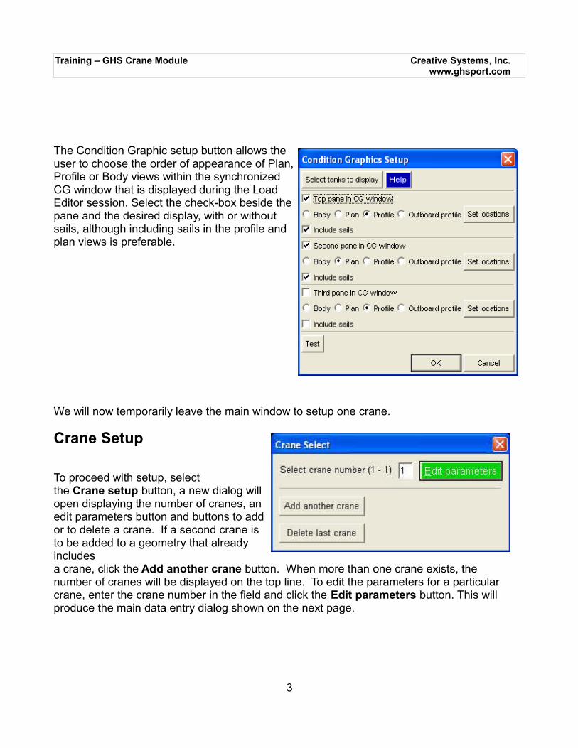
The Condition Graphic setup button allows theuser to choose the order of appearance of Plan,Profile or Body views within the synchronizedCG window that is displayed during the LoadEditor session. Select the check-box beside thepane and the desired display, with or withoutsails, although including sails in the profile andplan views is preferable.
We will now temporarily leave the main window to setup one crane.
Crane Setup
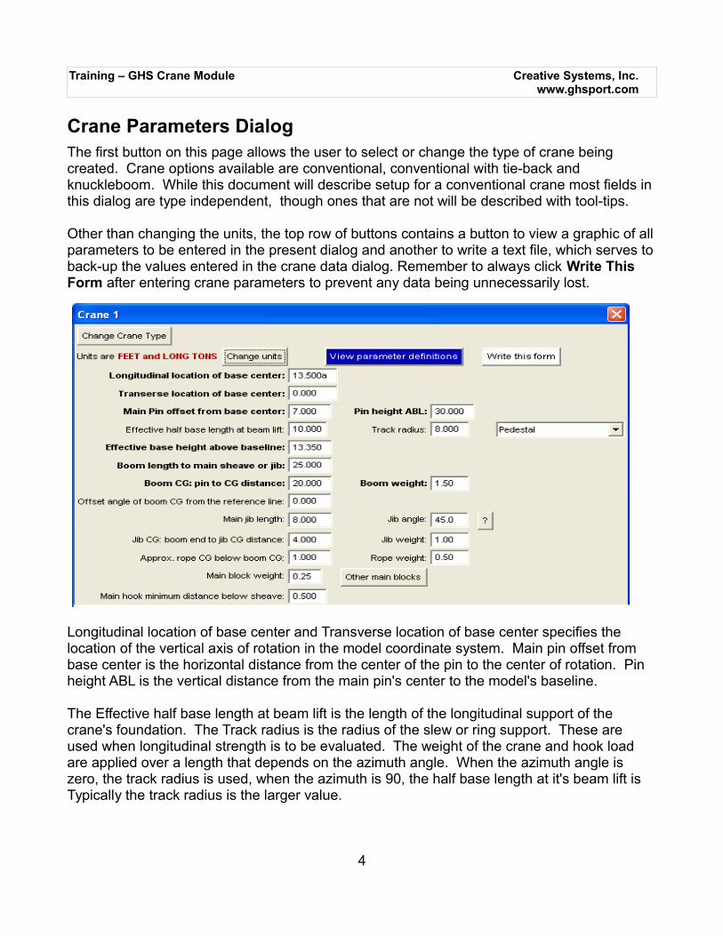
To proceed with setup, select the Crane setup button, a new dialog willopen displaying the number of cranes, anedit parameters button and buttons to addor to delete a crane. If a second crane isto be added to a geometry that alreadyincludes a crane, click the Add another crane button. When more than one crane exists, the number of cranes will be displayed on the top line. To edit the parameters for a particular crane, enter the crane number in the field and click the Edit parameters button. This will produce the main data entry dialog shown on the next page.
3
Training – GHS Crane Module Creative Systems, Inc.www.ghsport.com
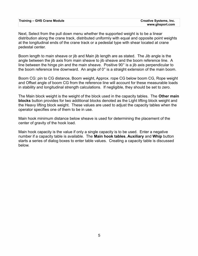
Crane Parameters DialogThe first button on this page allows the user to select or change the type of crane being created. Crane options available are conventional, conventional with tie-back and knuckleboom. While this document will describe setup for a conventional crane most fields in this dialog are type independent, though ones that are not will be described with tool-tips.
Other than changing the units, the top row of buttons contains a button to view a graphic of allparameters to be entered in the present dialog and another to write a text file, which serves toback-up the values entered in the crane data dialog. Remember to always click Write This Form after entering crane parameters to prevent any data being unnecessarily lost.
Longitudinal location of base center and Transverse location of base center specifies the location of the vertical axis of rotation in the model coordinate system. Main pin offset from base center is the horizontal distance from the center of the pin to the center of rotation. Pin height ABL is the vertical distance from the main pin's center to the model's baseline.
The Effective half base length at beam lift is the length of the longitudinal support of the crane's foundation. The Track radius is the radius of the slew or ring support. These are used when longitudinal strength is to be evaluated. The weight of the crane and hook load are applied over a length that depends on the azimuth angle. When the azimuth angle is zero, the track radius is used, when the azimuth is 90, the half base length at it's beam lift is Typically the track radius is the larger value.
4
Training – GHS Crane Module Creative Systems, Inc.www.ghsport.com
Next, Select from the pull down menu whether the supported weight is to be a linear distribution along the crane track, distributed uniformly with equal and opposite point weights at the longitudinal ends of the crane track or a pedestal type with shear located at crane pedestal center.
Boom length to main sheave or jib and Main jib length are as stated. The Jib angle is the angle between the jib axis from main sheave to jib sheave and the boom reference line. A line between the hinge pin and the main sheave. Positive 90° is a jib axis perpendicular to the boom reference line downward. An angle of 0° is a straight extension of the main boom.
Boom CG: pin to CG distance, Boom weight, Approx. rope CG below boom CG, Rope weight and Offset angle of boom CG from the reference line will account for these measurable loads in stability and longitudinal strength calculations. If negligible, they should be set to zero.
The Main block weight is the weight of the block used in the capacity tables. The Other mainblocks button provides for two additional blocks denoted as the Light lifting block weight and the Heavy lifting block weight. These values are used to adjust the capacity tables when the operator specifies one of them to be in use.
Main hook minimum distance below sheave is used for determining the placement of the center of gravity of the hook load.
Main hook capacity is the value if only a single capacity is to be used. Enter a negative number if a capacity table is available. The Main hook tables, Auxiliary and Whip button starts a series of dialog boxes to enter table values. Creating a capacity table is discussed below.
5
Training – GHS Crane Module Creative Systems, Inc.www.ghsport.com
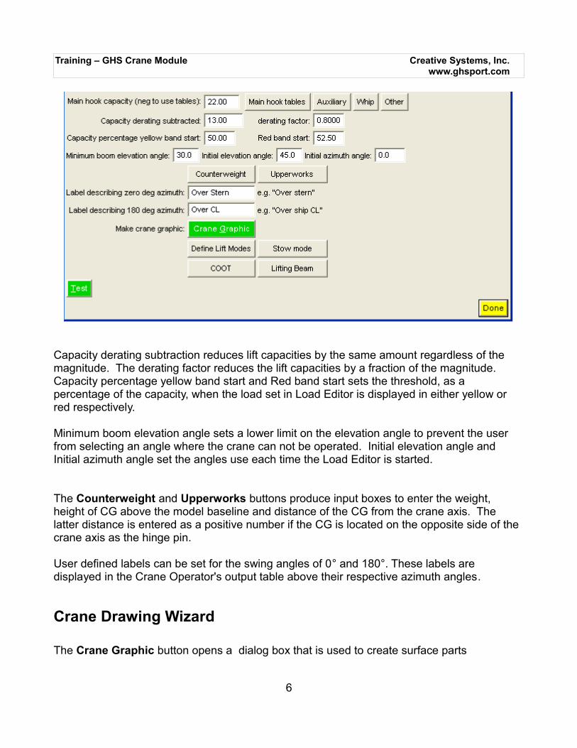
Capacity derating subtraction reduces lift capacities by the same amount regardless of the magnitude. The derating factor reduces the lift capacities by a fraction of the magnitude. Capacity percentage yellow band start and Red band start sets the threshold, as a percentage of the capacity, when the load set in Load Editor is displayed in either yellow or red respectively.
Minimum boom elevation angle sets a lower limit on the elevation angle to prevent the user from selecting an angle where the crane can not be operated. Initial elevation angle and Initial azimuth angle set the angles use each time the Load Editor is started.
The Counterweight and Upperworks buttons produce input boxes to enter the weight, height of CG above the model baseline and distance of the CG from the crane axis. The latter distance is entered as a positive number if the CG is located on the opposite side of the crane axis as the hinge pin.
User defined labels can be set for the swing angles of 0° and 180°. These labels are displayed in the Crane Operator's output table above their respective azimuth angles.
Crane Drawing Wizard
The Crane Graphic button opens a dialog box that is used to create surface parts
6
Training – GHS Crane Module Creative Systems, Inc.www.ghsport.com
representing the crane. The surface models are saved to new geometry files which are opened in the Load Editor / Condition Graphics window. The surface model of the crane will be updated realtime to represent the current azimuth and elevation angles.
If the geometry file being used for this analysis contains well defined crane parts, these part names can be entered in the “Use existing part name” dialogs, to better represent the crane surface geometry. For this introduction to crane geometry, we will use the wizard to create the various crane parts and will explain the values to enter in each input field.It is important to remember that some of the values to be entered here are independent of thepreviously defined crane parameters and others are based on those parameters. For all of the parts, a choice of nine colors is available. Gray, blue, green, cyan, red, magenta, brown, white and yellow.
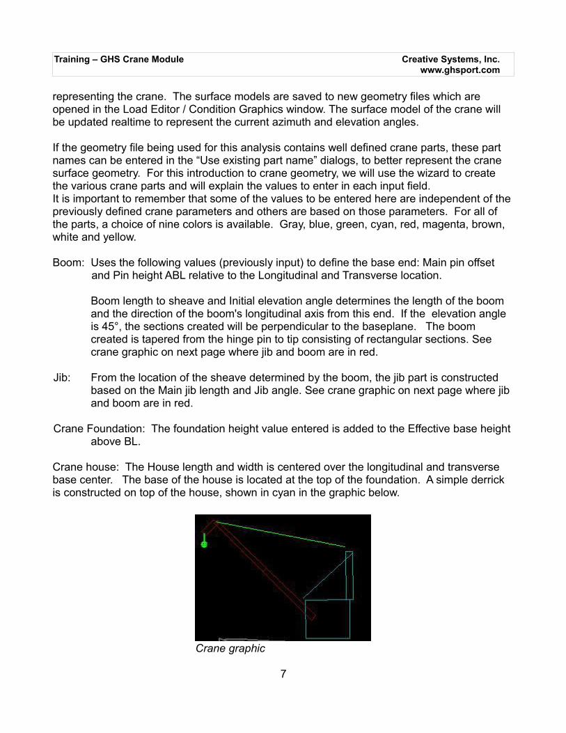
Boom: Uses the following values (previously input) to define the base end: Main pin offset and Pin height ABL relative to the Longitudinal and Transverse location.
Boom length to sheave and Initial elevation angle determines the length of the boom and the direction of the boom's longitudinal axis from this end. If the elevation angle is 45°, the sections created will be perpendicular to the baseplane. The boom created is tapered from the hinge pin to tip consisting of rectangular sections. See crane graphic on next page where jib and boom are in red.
Jib: From the location of the sheave determined by the boom, the jib part is constructed based on the Main jib length and Jib angle. See crane graphic on next page where jib and boom are in red.
Crane Foundation: The foundation height value entered is added to the Effective base heightabove BL.
Crane house: The House length and width is centered over the longitudinal and transverse base center. The base of the house is located at the top of the foundation. A simple derrick is constructed on top of the house, shown in cyan in the graphic below.
7
Crane graphic
Training – GHS Crane Module Creative Systems, Inc.www.ghsport.com
Top wires: Creates small parts connecting the sheave location to the point specified as the pin location. The pin height above base is the height above the top of the foundation/bottom of the house. Colored in green in the above graphical image.
Falls: Creates a part that always extends vertically downward from the sheave. The fall is colored green and hanging below the jib in the graphic above.
Clicking the Prepare specified geometry button will create a run file, CRD_MAKE.RF, and automatically execute it to create a geometry file with any of the following extensions GFC, .GFD,.GFE and GFX. The geometry extensions are created in successive order as needed by the wizard to prevent overwriting crane models. If multiple cranes are included in the geometry it's important to remember which crane extension, eg. GFC, GFD etc., was last created, and should be used as a base to add the new surface models to, thereby preventing any unnecessary loss of geometry
8
Training – GHS Crane Module Creative Systems, Inc.www.ghsport.com
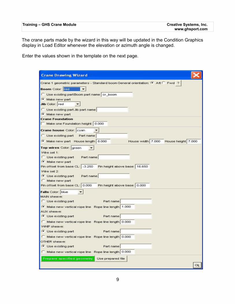
The crane parts made by the wizard in this way will be updated in the Condition Graphics display in Load Editor whenever the elevation or azimuth angle is changed.
Enter the values shown in the template on the next page.
9
Training – GHS Crane Module Creative Systems, Inc.www.ghsport.com
Testing the Geometry model
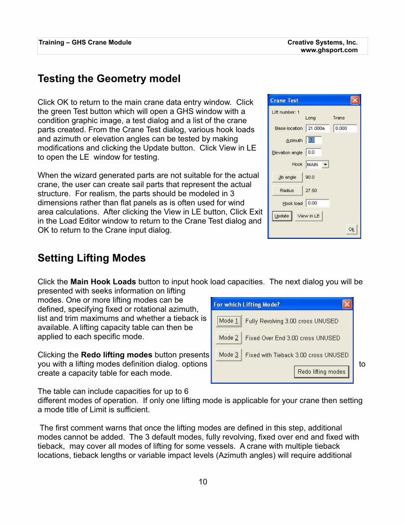
Click OK to return to the main crane data entry window. Clickthe green Test button which will open a GHS window with acondition graphic image, a test dialog and a list of the craneparts created. From the Crane Test dialog, various hook loadsand azimuth or elevation angles can be tested by makingmodifications and clicking the Update button. Click View in LEto open the LE window for testing.
When the wizard generated parts are not suitable for the actualcrane, the user can create sail parts that represent the actualstructure. For realism, the parts should be modeled in 3dimensions rather than flat panels as is often used for windarea calculations. After clicking the View in LE button, Click Exitin the Load Editor window to return to the Crane Test dialog andOK to return to the Crane input dialog.
Setting Lifting Modes
Click the Main Hook Loads button to input hook load capacities. The next dialog you will be presented with seeks information on liftingmodes. One or more lifting modes can bedefined, specifying fixed or rotational azimuth,list and trim maximums and whether a tieback isavailable. A lifting capacity table can then beapplied to each specific mode.
Clicking the Redo lifting modes button presentsyou with a lifting modes definition dialog. options to create a capacity table for each mode.
The table can include capacities for up to 6different modes of operation. If only one lifting mode is applicable for your crane then setting a mode title of Limit is sufficient.
The first comment warns that once the lifting modes are defined in this step, additional modes cannot be added. The 3 default modes, fully revolving, fixed over end and fixed with tieback, may cover all modes of lifting for some vessels. A crane with multiple tieback locations, tieback lengths or variable impact levels (Azimuth angles) will require additional
10
Training – GHS Crane Module Creative Systems, Inc.www.ghsport.com
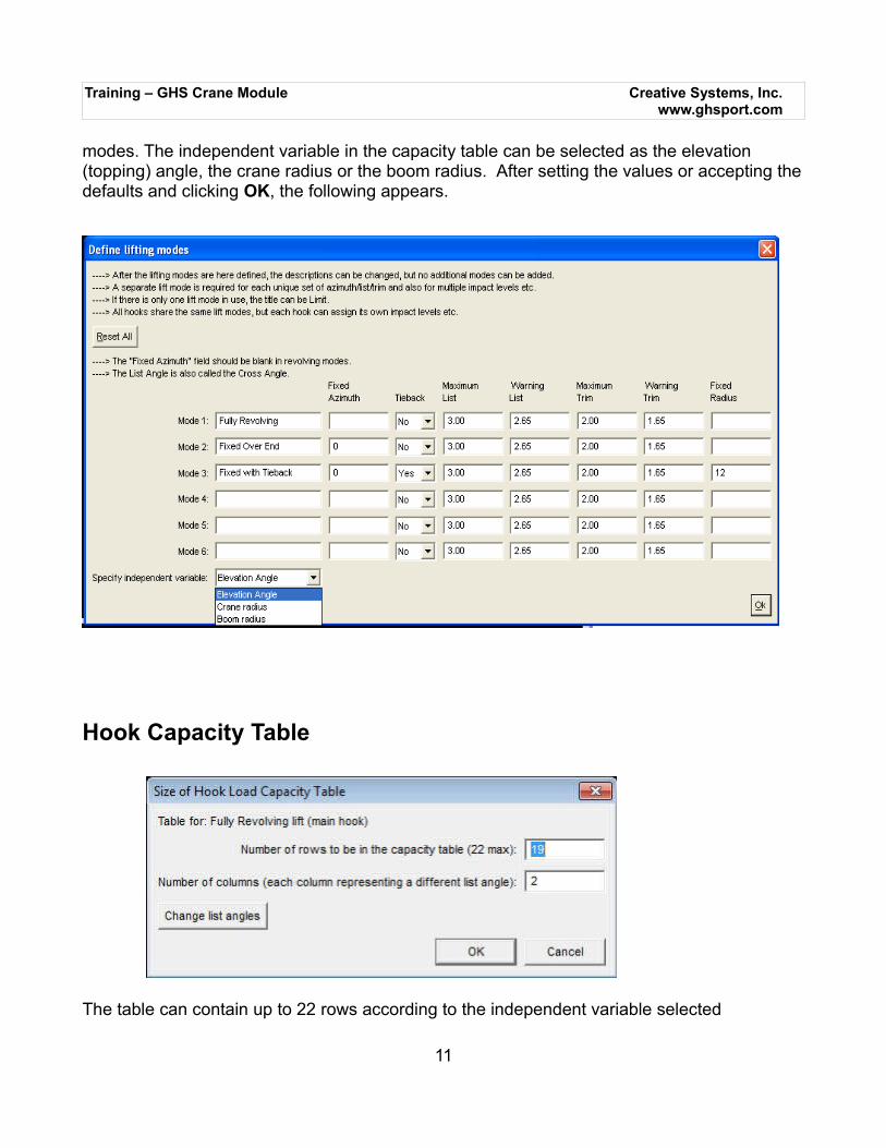
modes. The independent variable in the capacity table can be selected as the elevation (topping) angle, the crane radius or the boom radius. After setting the values or accepting thedefaults and clicking OK, the following appears.
Hook Capacity Table
The table can contain up to 22 rows according to the independent variable selected
11
Training – GHS Crane Module Creative Systems, Inc.www.ghsport.com
previously. For elevation angles from 0° to 90°, 19 rows would be required. The number of columns is dependent on the number of list (cross) angles for which a capacity limit is to be specified.
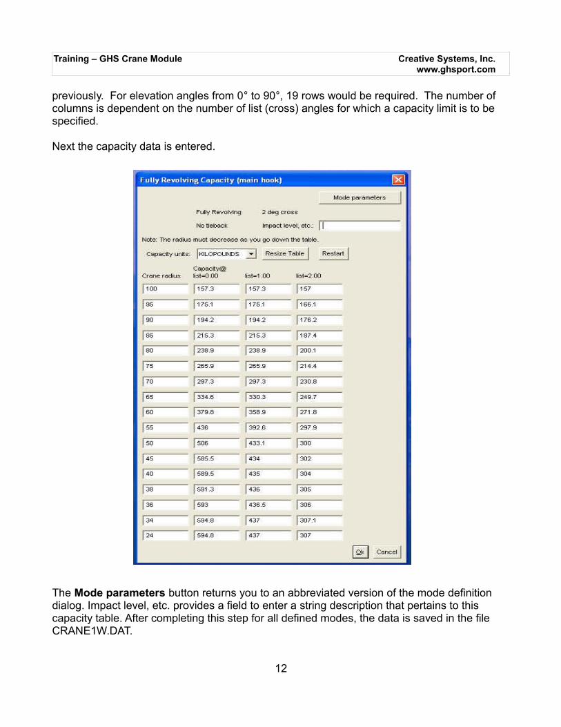
Next the capacity data is entered.
The Mode parameters button returns you to an abbreviated version of the mode definition dialog. Impact level, etc. provides a field to enter a string description that pertains to this capacity table. After completing this step for all defined modes, the data is saved in the file CRANE1W.DAT.
12
Training – GHS Crane Module Creative Systems, Inc.www.ghsport.com
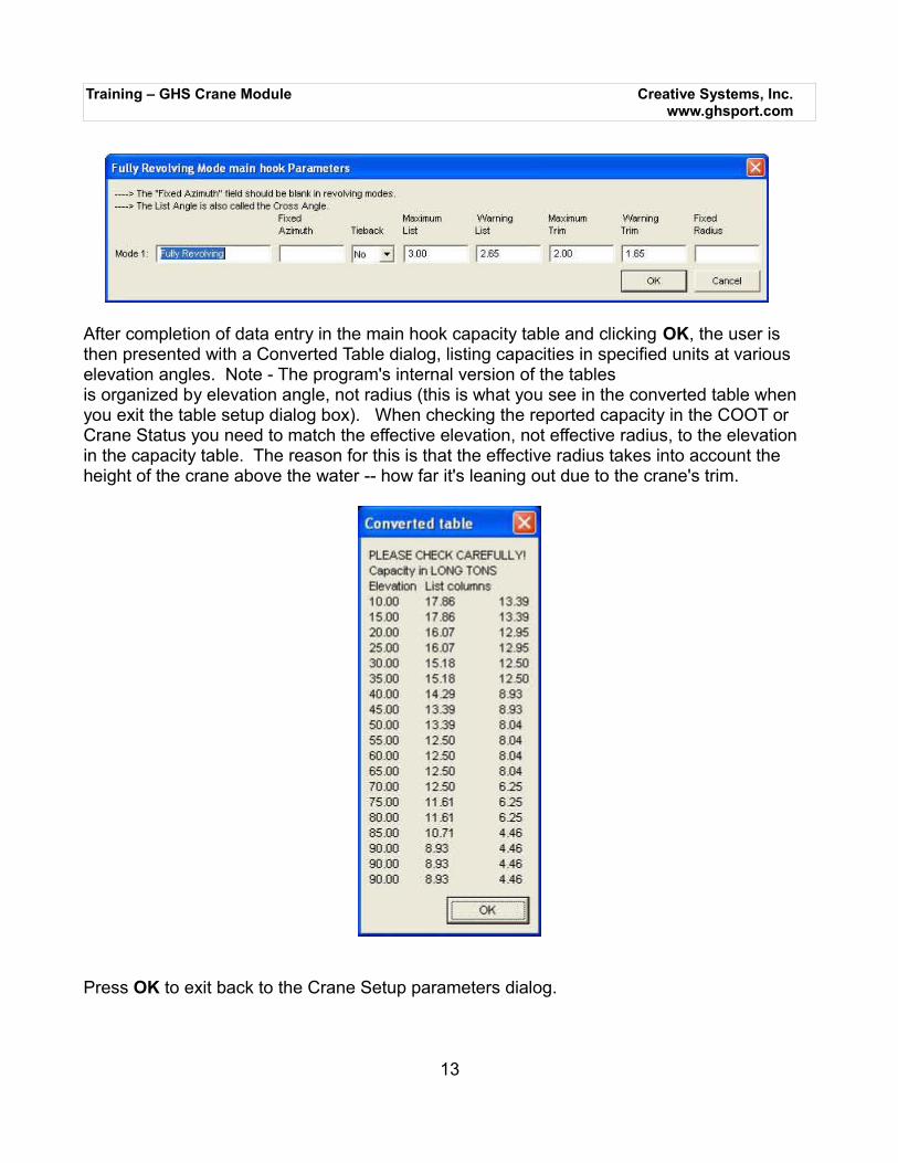
After completion of data entry in the main hook capacity table and clicking OK, the user is then presented with a Converted Table dialog, listing capacities in specified units at various elevation angles. Note - The program's internal version of the tablesis organized by elevation angle, not radius (this is what you see in the converted table when you exit the table setup dialog box). When checking the reported capacity in the COOT or Crane Status you need to match the effective elevation, not effective radius, to the elevation in the capacity table. The reason for this is that the effective radius takes into account the height of the crane above the water -- how far it's leaning out due to the crane's trim.
Press OK to exit back to the Crane Setup parameters dialog.
13
Training – GHS Crane Module Creative Systems, Inc.www.ghsport.com
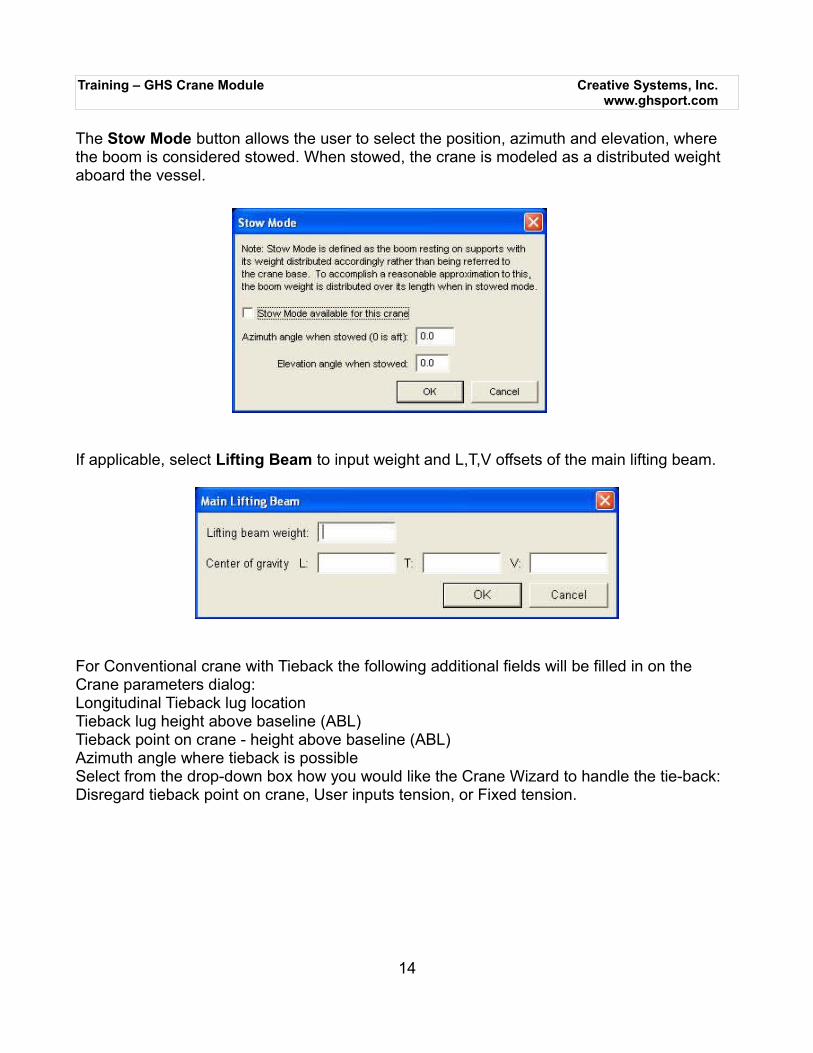
The Stow Mode button allows the user to select the position, azimuth and elevation, where the boom is considered stowed. When stowed, the crane is modeled as a distributed weight aboard the vessel.
If applicable, select Lifting Beam to input weight and L,T,V offsets of the main lifting beam.
For Conventional crane with Tieback the following additional fields will be filled in on the Crane parameters dialog:Longitudinal Tieback lug locationTieback lug height above baseline (ABL)Tieback point on crane - height above baseline (ABL)Azimuth angle where tieback is possibleSelect from the drop-down box how you would like the Crane Wizard to handle the tie-back: Disregard tieback point on crane, User inputs tension, or Fixed tension.
14
Training – GHS Crane Module Creative Systems, Inc.www.ghsport.com
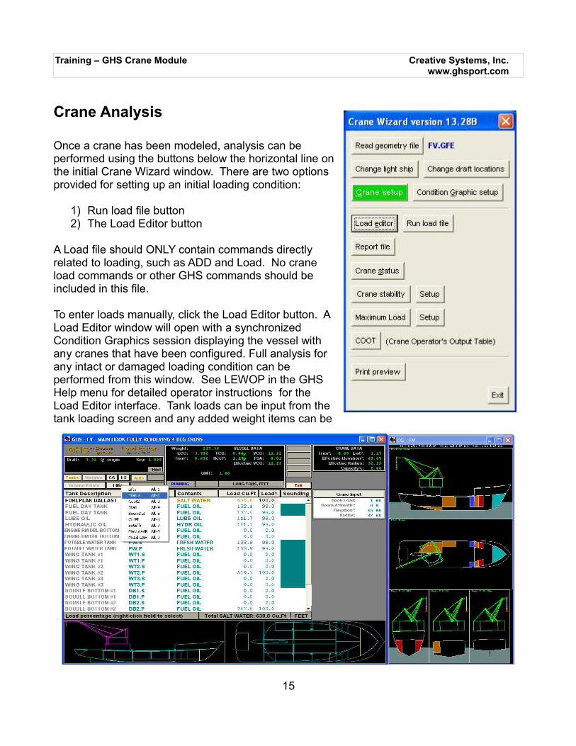
Crane Analysis
Once a crane has been modeled, analysis can beperformed using the buttons below the horizontal line onthe initial Crane Wizard window. There are two optionsprovided for setting up an initial loading condition:
1) Run load file button2) The Load Editor button
A Load file should ONLY contain commands directlyrelated to loading, such as ADD and Load. No craneload commands or other GHS commands should beincluded in this file.
To enter loads manually, click the Load Editor button. ALoad Editor window will open with a synchronizedCondition Graphics session displaying the vessel withany cranes that have been configured. Full analysis forany intact or damaged loading condition can beperformed from this window. See LEWOP in the GHSHelp menu for detailed operator instructions for theLoad Editor interface. Tank loads can be input from thetank loading screen and any added weight items can be
15
Training – GHS Crane Module Creative Systems, Inc.www.ghsport.com
included by clicking the Weights button. The CG button is useful if you mistakenly close the Condition Graphics window. If your GHS configuration includes Longitudinal Strength the LS button will be included for strength analysis.
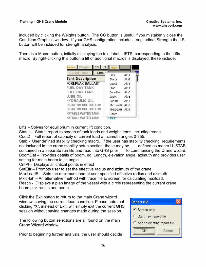
There is a Macro button, initially displaying the text label, LIFTS, corresponding to the Lifts macro. By right-clicking this button a lift of additional macros is displayed, these include:
Lifts – Solves for equilibrium in current lift condition.Status – Status report to screen of tank loads and weight items, including crane.Coot2 – Full report of capacity of current load at azimuth angles 0-355.Stab - User defined stability checking macro. If the user has stability checking requirements not included in the crane stability setup section, these may be defined as macro U_STAB,contained in a separate run file and read into GHS prior to commencing the Crane wizard.BoomDat – Provides details of boom, eg. Length, elevation angle, azimuth and provides user setting for main boom to jib angle.CritPt - Displays all critical points in effectSetEffr – Prompts user to set the effective radius and azimuth of the crane. MaxLoadR – Sets the maximum load at user specified effective radius and azimuth.Mxld-lah – An alternative method with trace file to screen for calculating maxload.Reach - Displays a plan image of the vessel with a circle representing the current crane boom pick radius and boom.
Click the Exit button to return to the main Crane wizardwindow, saving the current load condition. Please note thatclicking “X”, instead of Exit, will simply exit the current GHSsession without saving changes made during the session.
The following button selections are all found on the mainCrane Wizard window.
Prior to beginning further analysis, the user should decide
16
Training – GHS Crane Module Creative Systems, Inc.www.ghsport.com
whether to open a report file, append to an existing report or simply send output data to the screen. To open a report simply click the Report file button and select Start new report file. A subtitle can be provided at this stage or cancel to proceed. Set the report file name, page size, style and if necessary enter title page information. Click Open to open the report and return back to the main wizard window.
For a complete weight, load and crane status of the current condition select the Crane Statusbutton, then select one of the options presented to either send output to the screen, start a new report or append to an existing report file.
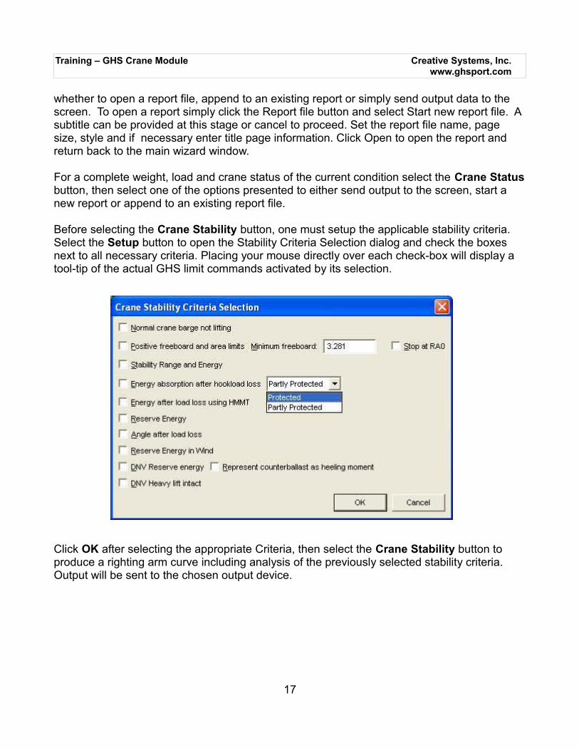
Before selecting the Crane Stability button, one must setup the applicable stability criteria. Select the Setup button to open the Stability Criteria Selection dialog and check the boxes next to all necessary criteria. Placing your mouse directly over each check-box will display a tool-tip of the actual GHS limit commands activated by its selection.
Click OK after selecting the appropriate Criteria, then select the Crane Stability button to produce a righting arm curve including analysis of the previously selected stability criteria. Output will be sent to the chosen output device.
17
Training – GHS Crane Module Creative Systems, Inc.www.ghsport.com
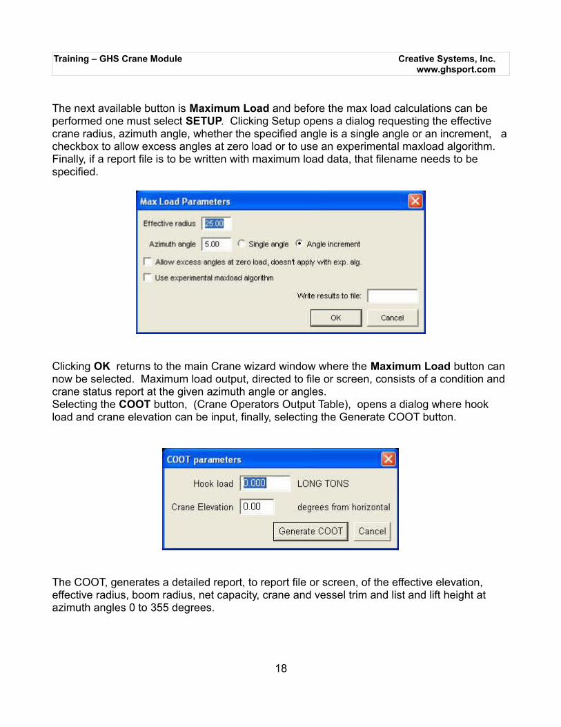
The next available button is Maximum Load and before the max load calculations can be performed one must select SETUP. Clicking Setup opens a dialog requesting the effective crane radius, azimuth angle, whether the specified angle is a single angle or an increment, acheckbox to allow excess angles at zero load or to use an experimental maxload algorithm. Finally, if a report file is to be written with maximum load data, that filename needs to be specified.
Clicking OK returns to the main Crane wizard window where the Maximum Load button can now be selected. Maximum load output, directed to file or screen, consists of a condition and crane status report at the given azimuth angle or angles.Selecting the COOT button, (Crane Operators Output Table), opens a dialog where hook load and crane elevation can be input, finally, selecting the Generate COOT button.
The COOT, generates a detailed report, to report file or screen, of the effective elevation, effective radius, boom radius, net capacity, crane and vessel trim and list and lift height at azimuth angles 0 to 355 degrees.
18