Embed Size (px)
Citation preview
ATCZ175 InterOP PROJECT
Working Prinicple of WLAN Systems andInterference Sources
Institute of Electrodynamics, Microwave and Circuit EngineeringTechnische Universität Wien
Advisor:Assoc. Prof. Dipl.-Ing. Dr.techn. Holger Arthaber
byProj. Ass. Dipl.-Ing. Christian Spindelberger
October 9, 2019

Contents1 Introduction 1
2 IEEE 802.11 Wireless LAN 12.1 Medium Access Control Layer . . . . . . . . . . . . . . . . . . . . . . . . . 22.2 Physical Layer . . . . . . . . . . . . . . . . . . . . . . . . . . . . . . . . . . 72.3 Higher-Layer Protocols . . . . . . . . . . . . . . . . . . . . . . . . . . . . . 12
3 Interference Sources 133.1 Bluetooth Low Energy . . . . . . . . . . . . . . . . . . . . . . . . . . . . . 133.2 Short Range Devices . . . . . . . . . . . . . . . . . . . . . . . . . . . . . . 163.3 Microwave Ovens . . . . . . . . . . . . . . . . . . . . . . . . . . . . . . . . 173.4 Radar Systems . . . . . . . . . . . . . . . . . . . . . . . . . . . . . . . . . 18
References 19
i

AbbreviationsACK acknowledgment
BLE Bluetooth low energy
BPSK binary phase shift keying
CCA clear channel assessment
CP cyclic prefix
CTS clear to send
DIFS distributed interframe space
DSSS direct spread spectrum sequence
EIRP effective isotropic radiated power
FCS frame check sequence
FEC forward error correction
FFT fast Fourier transform
FH frequency hopping
GFSK Gaussian frequency shift keying
IoT internet of things
IP internet protocol
ISM industrial, scientific, and medical
IFS interframe space
IFFT inverse fast Fourier transform
LAN local area network
LLC logical link control
LTF long training field
MAC medium access control
ii
MTU maximum transmission unit
NAV network allocation vector
OFDM orthogonal frequency division multiplexing
OSI open systems interconnection
PER packet error rate
PHY physical
PLCP physical layer convergence procedure
PMD physical medium dependent
QAM quadratue amplitude modulation
RF radio frequency
RIFS reduced interframe space
RSSI received signal strength indicator
RTS request to send
SIFS short interframe space
SRD short range device
STF short training field
TCP transmission control protocol
UDP user datagram protocol
WLAN wireless local area network
iii

1 IntroductionThis document provides a theoretical background of wireless local area network (WLAN)communication systems. The aim is to make the reader familiar with relevant conceptsand parameters. It mainly consists of a WLAN related part, discussing important topicssuch as layer stack up, collision avoidance, and transmission parameters, while commoninterference sources (Bluetooth low energy (BLE), microwave ovens, SRDs, and radars)affecting WLAN are presented in the second part.
Starting with Section 2, an introduction about the WLAN-related layer stack up and sim-ilarities to other transmission standards is given. Proceeding with this topic, the two mostimportant parts concerning this work are discussed. The medium access control (MAC) isdescribed in terms of timing constraints, collision avoidance, and layer interaction. Further-more, physical (PHY)-layer parameters, such as modulation techniques (OFDM, DSSS)and carrier sensing, are examined. In order to explain these sublayer interactions, prac-tice relevant examples utilizing the user datagram protocol (UDP) and transmission con-trol protocol (TCP) are given. Lastly, basics about potential interference sources will bepresented in Section 3. BLE is one of the most serious interferers concerning WLAN.Therefore, details about the PHY layer and channel access schemes are investigated. Thefinal subsections are devoted to further interferers, i.e., microwave ovens, short range de-vices (SRDs), and radars.
2 IEEE 802.11 Wireless LANWLAN is a widely deployed standard for data transmission in the industrial, scientific,and medical (ISM) band. Usually, it is intended to be used as a wireless access pointto a network (router). Since the first launch in 1997, the IEEE 802.11 standard has un-dergone several improvements [1]. Today, different versions are available, such as IEEE802.11a/b/g/n/ac and many more. In the internet of things (IoT) branch, the state-of-the-art WLAN standard is IEEE 802.11n, implemented with one single antenna. There-fore, the focus will lie on this respective version. The current section about IEEE 802.11WLAN properties is based on 802.11 Wireless Networks: The Definitive Guide, written byMatthew Gast [2].
As the layer composition of IEEE 802.11 strongly relates to IEEE 802-based networks,i.e., local area network (LAN), the low level constructs (MAC & PHY) must fit into therequired open systems interconnection (OSI) model (Figure 1). The most important parts,considering WLAN, are marked in violet. It is obvious that all IEEE 802 networks have aMAC and a PHY component. The classical data link layer is responsible for an error free
1

transmission by calculating checksums or making use of channel coding. While the MACdetermines specific rules for collision avoidance and how to access the medium, the PHYlayer is related to details about data reception and transmission. Thus, WLAN uses theIEEE 802.2 logical link control (LLC) encapsulation, which makes it very powerful becauseit can utilize higher layer protocols (UDP, TCP). Details about the sublayer realizationswill be discussed in the following.
802.11 MAC
802.11 PHY
OFDM
802.11 PHY
DSSS
802.2 Link layer control (LLC)
802.5
MAC
802.5
PHY
802.3
MAC
802.3
PHY
802
Overview
and
Architecture
802.1
Management
Physical- layer
Link- layer
Figure 1: OSI model of IEEE 802.11 embedded in IEEE 802.2 LLC [2]
2.1 Medium Access Control LayerThe access medium of IEEE 802.11 systems is a wireless radio channel and demands specificMAC properties to ensure stable data transmissions. Especially for unlicensed radio chan-nels, e.g., the ISM band, many different interferers such as BLE and microwave ovens occur.Therefore, to check if a transmission was successful, WLAN uses acknowledgment (ACK)frames for confirmation. Figure 2 depicts, how a simple frame transmission between twostations works. Station one (STA 1 ) transmits the desired frame to receiver station two(STA 2 ). If the transmission was successful, STA 2 replies with an ACK frame. Detectinga damaged packet forces STA 2 to omit an answer. Depending on the utilized protocol, aretransmission will be sent if the ACK frame was missing.
Frame
ACK
STA 1 STA 2
Tim
e
Figure 2: Valid WLAN frame transmission [2]
2

Hidden Node Problem
A major problem arises concerning multi-user scenarios. Because of limited transmit pow-ers, free space losses, channel variations, and several other effects, the range of a stationis limited. This makes it impossible to reach those users that are too far from the station.Assume the following scenario: One access point (server) and two further stations (clients)are present. The first client (client 1 ) wants to start a data exchange with the server, butthe second client (client 2 ) is too far away to receive any message from client 1. Whatnow happens, is that the transmission is corrupted if client 2 also starts a conversationwith the server at the same time. This is called the hidden node problem.
Frame
ACK
RTS
CTS
Client 1
Server
Client 2
Client 1 Server
Tim
e
Figure 3: Hidden node problem: distribution of the involved stations and their rangessketched by colored circles (left), utilization of the RTS-CTS transaction over time (right)[2]
To prevent such errors, the MAC is able to introduce request to send (RTS) and clear tosend (CTS) frames. Now, before client 1 starts a transmission, it first sends an RTS frameand waits for a CTS reply by the server. Then, client 2 also receives this frame and holdsthe channel free. Figure 3 shows this scenario in detail. On the left side, three WLANstations are visible. The colored circles mark the respective ranges. Obviously, client 1 and2 cannot reach each other. Consequently, the RTS-CTS transaction is performed (rightside of Figure 3).
Generally, long data frames tend to be corrupted in a noisy environment. Therefore, WLANoffers two ways to mitigate this problem. The first one is to fragment long sequences intoshort ones and the second is to implement an RTS-CTS exchange. The indicator for sucha transaction is given by the RTS threshold. If the frame length is larger than the definedthreshold, an RTS is utilized.
3

Usually, the fragmentation and RTS threshold are of the same size.
Network Allocation Vector
The MAC header of WLAN frames (Figure 6) introduces the signal duration field, alsocalled network allocation vector (NAV), which can be used to hold the channel free fromWLAN interference for a defined time period. This method is called virtual carrier-sensing.Figure 4 depicts a transmission sequence between sender and receiver with an RTS-CTStransaction.
Sender
Receiver
NAVNAV (RTS)
NAV (CTS)
SIFS
SIFS
SIFS DIFS
Time
Time
Figure 4: Signal duration indicator [2]
When a frame transmission between two stations starts, the NAV is also received by allother reachable stations and each of them starts a timer. In this time, the channel isheld free from WLAN interference until the timer elapses. Furthermore, the NAV can beupdated if the frames have been fragmented before. It must be mentioned that the NAVis also sent for transmissions without an RTS and CTS sequence.
DIFS
SIFSContention window
Backoff
slotsTime
Figure 5: IFS: time constraints which have to elapse before proceeding with a new trans-mission [2]
4

Interframe Spacing
One can notice the marked spaces SIFS and DIFS in Figure 4. They are called IFSs. IFSsare utilized to coordinate the channel access among multiple WLAN stations. In IEEE802.11, several different types are defined depending on the frame type. In the following,the most important ones will be discussed. Figure 5 depicts how they relate to each other.
Short interframe space (SIFS):Only high-priority events, such as RTS, CTS, and ACK frames are allowed to transmitafter one SIFS has elapsed. If such a high-priority transmission has started, the mediumbecomes busy. Thus, frames transmitted after SIFSs have a higher priority than, for ex-ample, frames that are transmitted after DIFS.
Distributed interframe space (DIFS):Determines the minimum idle time which must elapse before a contention based transmis-sion can be started. One DIFS is followed by a contention window with 31 slots. Theseslots are chosen randomly by a station and are equally distributed. Now, the station whichchooses the first slot, relative to the others, wins and is allowed to transmit a frame after-wards. If two stations choose the same slot and interfere with each other, another greatercontention window is utilized.
IFS 2.4 GHz 5 GHzSIFS 10 µs 16 µsDIFS 28 µs 34 µsRIFS 2 µs 2 µs
Table 1: IFS durations for IEEE 802.11n
Table 1 provides information on typical IFS lengths in IEEE 802.11n. In order to decreaselatency effects, another type is introduced, called the reduced interframe space (RIFS). Itis the shortest space used in IEEE 802.11n. Since newer WLAN revisions launched to themarket, RIFSs are often deactivated per default in networks to maintain compatibility.
Frame Format
Corresponding to Figure 1, WLAN utilizes the IEEE 802 LAN topology. Hence, it makesuse of the internet protocol (IP) for linking with other stations. In order to address aspecific receiver under the mentioned challenges in a wireless data link, the MAC layergenerates defined frames. For instance, such sequences let the receivers know if they haveto respond or not. Figure 6 depicts a generic MAC frame structure.
5

FrameControl
2 Bytes
Address 1
6 Bytes
DurationID
2 Bytes
Address 2
6 Bytes
Address 3
6 Bytes
Seq-control
Frame body
0-2304 Bytes
FCS
4 Bytes2 Bytes
Figure 6: Generic IEEE 802.11 MAC frame [2]
The MAC frame is a very powerful part with plenty configurable properties. Therefore,only the most important ones are presented in the following.
Frame control:Gives the receiver information about the frame type. In the IEEE 802.11 standard, threedifferent types exist: management, control, and data frames. Management frames are typ-ically broadcasted by access points or association communications. In the section abouthidden node problems, RTS and CTS have been introduced, which are control frames. Thelast type is, due to its name, self explanatory and simply transmits data.
Duration/ID:The most important use case of the duration field is the virtual carrier-sensing called NAV.With this information each receiver knows for how long the medium will be busy.
Address fields:The address fields contain the MAC addresses of the receiver and transmitter. The thirdaddress is used for filtering the basic service set ID to identify different networks (accesspoints) in the same area.
Frame body:Moves data between two stations corresponding to higher layer protocols, such as UDP orTCP. The maximum payload in IEEE 802.11 is a data amount of 2,304 Byte. However,in conventional systems, the maximum amount of data is 1,500 Byte. This length is deter-mined by the maximum transmission unit (MTU) size of a system, which will be discussedin Section 2.3.
FCS :The frame check sequence (FCS) provides the receiver with information whether the re-ceived data packet is damaged. The transmitter sends the FCS within the MAC frameand the receiver recalculates the FCS. The transmission is expected to be correct if thetwo check sums match. Otherwise, the ACK frame is not sent back and a retransmissionis forced, depending on the used protocol.
At the end, the total MAC frame is passed to the PHY layer, which applies further oper-ations onto data.
6

2.2 Physical LayerThe lowest sublevel of the IEEE 802.11 architecture is the PHY layer. In this section, theworking principle and further common topics, which appear in the PHY-layer management,will be discussed in detail.
802.2
Layer 2: Data link (MAC)
Layer 1: PhysicalPLCP
PMD
Figure 7: Interaction between MAC and PHY [2]
Figure 7 depicts the PHY-layer structure. It consists of two main parts, the physicallayer convergence procedure (PLCP) sublayer and the physical medium dependent (PMD)sublayer. The PLCP sublayer can be interpreted as the interface between MAC and PHYlayers. It adds a specific header for frame detection and synchronization to the framepassed by the MAC. Lastly, the PMD sublayer transmits the provided data from the PLCPsublayer by using the radio frequency (RF) front-end. Furthermore, the PHY layer utilizesanother important application to mitigate interference perturbations, called clear channelassessment (CCA). The CCA indicates if the medium is idle or busy. This information isdirectly passed to the MAC for collision avoidance.
FEC
Coder
Interleaving &
MappingIFFT
GI
Addition
I/Q
ModulatorPA
Figure 8: IEEE 802.11 transmission chain [1]
Modulation
The PMD sublayer of current WLAN systems is capable of two different modulation types,called direct spread spectrum sequence (DSSS) and orthogonal frequency division multi-plexing (OFDM). DSSS is the older version of the two, but still in use in the IEEE 802.11bstandard. With this technique, a bitrate of 11 Mbits/s at 22 MHz bandwidth is achieved.
7

In newer standard revisions, the OFDM modulation has carried through due to its higherdata rates and smaller bandwidth. The main advantages of OFDM are robustness againstmultipath fading and simplicity of channel estimation. As IEEE 802.11n utilizes the OFDMmodulation only, the focus in this section will lie on this technique.
Figure 8 depicts the transmitter chain of the PMD sublayer in IEEE 802.11n (single an-tenna). At the beginning, a given bitstream is encoded by a forward error correction (FEC)coder. Afterwards the data is interleaved, together with the encoding, ensuring a betterperformance due to added redundancy and data reordering. The following path can beviewed as an OFDM modulator (Figure 9), which consists mainly of two parts, the OFDMmodulation and the cyclic prefix (CP) extension.
Figure 9: OFDM modulation (top) and applying the cyclic prefix extension (bottom) [3]
The encoded bitstream is mapped onto a desired scheme, for instance, quadratue amplitudemodulation (QAM) or binary phase shift keying (BPSK). Afterwards, the serial symbolsequence is transposed into a column vector. Now, the next step is to apply an inversefast Fourier transform (IFFT). At last, the CP is added to the OFDM symbol. The CPis a fractional part of the created OFDM symbol after applying the IFFT. It is appendedto the beginning of the respective symbol, yielding several advantages discussed in thefollowing. After another transpose to a row vector, the baseband signal is mixed up to thedesired frequency and passed through the channel.
The cyclic prefix, together with the fast Fourier transform (FFT), offers a major advantage.The receiver stage detects a WLAN frame, strips off the CP and demodulates the signalaccordingly with the FFT. Thus, the detected signal is in the frequency domain and thechannel estimation results in a simple mathematical division. Nonetheless, the FFT ensuresorthogonality only if the signal is periodic, which is established with the CP. Through theperiodicity introduced by the CP, the convolution with the channel is circular. Therefore,
8
with its use, it is possible to absorb all multipath components up to a delay which is notlonger than the CP itself. This technique makes OFDM robust against multipath fading.
-10 -8 -6 -4 -2 0 2 4 6 8 10
f (MHz)
-30
-20
-10
0
10
20
30
40
PS
D (
dbm
/Hz)
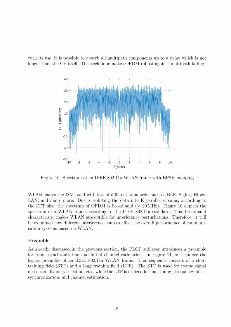
Figure 10: Spectrum of an IEEE 802.11a WLAN frame with BPSK mapping
WLAN shares the ISM band with lots of different standards, such as BLE, Sigfox, Hiper-LAN, and many more. Due to splitting the data into K parallel streams, according tothe FFT size, the spectrum of OFDM is broadband (≥ 20 MHz). Figure 10 depicts thespectrum of a WLAN frame according to the IEEE 802.11a standard. This broadbandcharacteristic makes WLAN susceptible for interference perturbations. Therefore, it willbe examined how different interference sources affect the overall performance of communi-cation systems based on WLAN.
Preamble
As already discussed in the previous section, the PLCP sublayer introduces a preamblefor frame synchronization and initial channel estimation. In Figure 11, one can see thelegacy preamble of an IEEE 802.11a WLAN frame. This sequence consists of a shorttraining field (STF) and a long training field (LTF). The STF is used for coarse signaldetection, diversity selection, etc., while the LTF is utilized for fine timing-, frequency-offsetsynchronization, and channel estimation.
9

Figure 11: Preamble of an OFDM IEEE 802.11 frame [4]
The STF field consists of a ten times repeated 0.8 µs long training sequence. These fieldsare generated according to a Barker sequence. This type ensures that the autocorrelationfunction is minimal at off-peak values. Due to this repeated structure, a certain algorithm,invented by Schmidl and Cox, can be implemented for coarse frame detection [5].
The LTF field is again 8 µs long, but consists of two repeated sections including a longguard interval. This field is used for fine timing- and frequency-offset synchronization byimplementing, for instance, a matched filter. More details about detection and synchro-nization schemes will follow later.
The signal (SIG) field gives the receiver information about the used modulation, codingrate, frame length, and used standard. In order to provide compatibility for all standards,the symbol mapping of the SIG field is always done by utilizing BPSK. Since newerstandards, like the IEEE 802.11n, make use of multiple antennas, beamforming, and severaldiversity techniques, the preamble becomes longer to provide the required information.
Clear Channel Assessment
In the previous section about the MAC layer, the NAV was introduced. This vector isused for virtual carrier sensing, providing a technique for collision avoidance in a mult-iuser scenario. In order to detect further interfering signals, such as BLE or microwaveovens, the PHY layer adds another method to mitigate interference effects. Before everytransmission, the physical layer starts a CCA sequence according to Figure 12. Before astation is allowed to transmit, it listens to the channel, finding out if it is busy or not. Thechannel sensing consists of two parts. Firstly, a preamble detection with the Schmidl andCox algorithm is performed. Secondly, an energy detector, which samples data within 4 µs,
10

is implemented. In the IEEE 802.11a standard, it is specified that the preamble detectionmust work down to a power level of −82 dBm and the energy detection down to −62 dBmin order to detect every other kind of interference. It must be mentioned here, that state-of-the-art WLAN modules do achieve a much better preamble detection power level of about−92 dBm. If the channel is determined to be free for at least a distributed interframespace (DIFS), a contention window is started. After transmitting the desired frame, thechannel is sensed for collision detection again. In the case of detecting interference, violatingIFS timing constraints, the backoff strategy is started again. Otherwise, the transmissionis completed.
Station is
ready to send
Sense
channel
Channel free
Collision detected
No collision detected
Transmit data
and
sense channel
Transmission
completed
Wait according
to
backoff strategy
Wait until
interferer
finished
New attempt
Channel busy
Figure 12: CCA: flow diagram (left), channel sensing thresholds (right) [1]
It must be emphasized that the channel sensing scheme becomes a threshold decisionproblem and influences the performance of WLAN systems. The throughput between twostations might be reduced significantly if the threshold is set to low values in crowded areas.This problem could be skipped if the threshold is set to the maximum of −82 dBm. Con-sequently, the received signal power of the two stations must be high enough to neglect theresidual interference beyond this power level. One must notice that this solution will onlywork if the stations are close to each other, since the transmit power in WLAN is limitedto about 20 dBm. In addition to this aspect, the decision threshold becomes importantfor power-critical applications, such as battery-powered devices. Typically, stations adjusttheir transmit power according to a received signal strength indicator (RSSI) for savingenergy. Naturally, this tactic succeeds only if the receiver does not neglect the utilizedpower level, attenuated by the channel.
11

2.3 Higher-Layer ProtocolsWLAN utilizes the IEEE 802 LLC encapsulation. Therefore, it is able to work with higherOSI layers. In Figure 1, only the first two layers are presented, but the general modelconsists of seven layers in total. As the goal of this project is to describe interferencemechanisms in WLAN systems, it is necessary to characterize them. In order to measureinterference effects in real world systems, packet error rates (PERs), throughput, and re-transmissions are investigated. Hence, to understand how interference effects on WLANsystems can be characterized, two more layers have to be considered.
Network Layer
This layer mainly routes the best logical paths between two nodes for an efficient dataexchange. Typical hardware devices which relate to the network layer are, for instance,routers, bridges, and switches. In addition to this, it is capable to transmit variabledata lengths. If the message is too large for the utilized communication standard, it isfragmented into frames. The maximum data length is defined by the MTU. The MTU sizein Ethernet networks is defined to be 1,500 Byte long. Therefore, every payload data thatis to be transmitted is fragmented into frames if it exceeds the MTU size. Furthermore, itis able to send these fragments independently and reassemble them again at the receiverside.
Transport Layer
The fourth instance of the OSI model establishes a reliable data link to a desired destina-tion by maintaining quality of service functions, such as flow control, segmentation, anderror detection. Depending on the used protocol, the transport layer can enforce retrans-missions of packets due to a missing ACK frame. The two most important protocols forthis project are the UDP and the TCP.
User datagram protocol (UDP):UDP is a simple transport layer protocol. Because of the FCS introduced by the MACframe, UDP is capable to detect errors. However, there is no guarantee that the messagehas been transmitted successfully. The transmission procedure starts by simply sendingthe frame. This means that no handshake with the receiver side is necessary. If the trans-mission was successful, an ACK frame is replied, but if not, the transmitter does not forcea retransmission. Hence, UDP always sends packets with maximum data rate and will beused for PER and throughput tests in this work. It must be mentioned that this protocolis not applicable for services which require a high reliability. Therefore, it is often used forapplications with an error tolerance, such as video streaming or gaming servers.
12

Transmission control protocol (TCP):TCP is a more complex protocol compared to UDP. It implements a linking management,flow control, and error detection. These properties will be explained by a simple dataexchange example. First of all, the transmitter establishes a connection with the receiverbefore a data transfer is started. After each packet, an ACK frame is sent back or not,depending on the error detection. If the ACK frame is missing, a timer is started, af-ter which the damaged packet is retransmitted. During payload data transmission, TCPcontrols the throughput and adapts it according to occurring retransmissions. At thebeginning, it starts with a small window size and increases it continuously until a retrans-mission is necessary. Thus, it reacts dynamically to interference effects. At the end ofa data exchange, the connection is terminated. Consequently, the two involved stationsare always in contact with each other to ensure a highly reliable connection. The mainapplications of TCP are, for example, email exchanges.
3 Interference SourcesAlthough WLAN is capable of various techniques for interference mitigation, the perfor-mance in terms of throughput, PER, and retransmissions is still limited. In the following,common interference effects and the respective sources will be described in detail.
Under ideal conditions, when a given channel is used only by WLAN systems with sufficienttransmit power, no interference effects occur because of MAC- and PHY-layer constraints.Unfortunately, in real world scenarios, many distributed access points and their local asso-ciated clients share the same channel and the hidden node problem is inevitable. As alreadyexplained, this effect is handled by an RTS-CTS transaction. Nevertheless, this problemleads to transmission perturbations for packets that are smaller than the RTS threshold.Furthermore, if a DIFS (Figure 5) has elapsed after a transmission, it is statistically pos-sible that some stations pick the same time slot of the backoff window. This would alsolead to interference effects. Since these events do not consider co-existence problems withother standards or microwave ovens, the most important sources are investigated in thefollowing.
3.1 Bluetooth Low EnergyAt the beginnings of Bluetooth the main focus was put on connecting cell phones to laptops.Later on, its main application became establishing an audio link between headphones anda smart phone. As these applications required an increased throughput, the data rate ofnewer Bluetooth-standard revisions was increased from a basic rate of 1 Mbit/s to hundredsof megabits per second. It is clear that an increased throughput causes a reduced batterylifetime.
13

-10 -8 -6 -4 -2 0 2 4 6 8 10
f (MHz)
-200
-180
-160
-140
-120
-100P
SD
(db
m/H
z)
WLANBLE
0 50 100 150 200 250 300
t (µs)
-150
-120
-90
-60
-30
Pow
er (
dbm
)
WLANBLE
Figure 13: BLE vs. WLAN: spectrum (top) and envelope (bottom)
Therefore, BLE has been launched for low-power applications. It was designed for shortlasting communications, for instance, incorporated by wireless sensors. Because of this low-power consumption, it is widely used in the IoT branch besides WLAN. Since BLE doesnot perform collision avoidance in higher layers (MAC layer), the subject of this section ishow the PHY layer of BLE works and which co-existence problems arise [6].
Physical Layer
The PHY layer of BLE utilizes Gaussian frequency shift keying (GFSK) with a bitrateof 1 or 2 Mbits/s and an according bandwidth of 1 or 2 MHz. This modulation keeps thespectral efficiency high by optimizing transitions between symbols. Figure 13 depicts thespectrum and envelope of a BLE- compared to a WLAN packet. Because of the usedmodulation, the side lobes are decaying fast and ensure low co-channel interference. Incomparison with OFDM, the envelope of GFSK signals appears to be almost constantwhile OFDM shows a noise-like behavior. As a consequence, these two modulation typespresumably behave differently as interferers.
BLE uses up to 36 channels in the 2.4 GHz ISM band for data transmission and partlycoincides with WLAN bands corresponding to Figure 14. Furthermore, it must be noticedthat static advertiser channels are placed for device coupling communications outside of
14
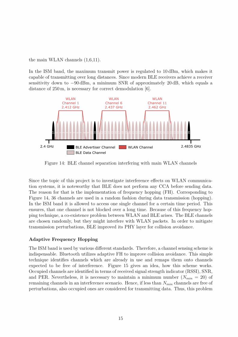
the main WLAN channels (1,6,11).
In the ISM band, the maximum transmit power is regulated to 10 dBm, which makes itcapable of transmitting over long distances. Since modern BLE receivers achieve a receiversensitivity down to −90 dBm, a minimum SNR of approximately 20 dB, which equals adistance of 250 m, is necessary for correct demodulation [6].
WLAN
Channel 1
2.412 GHz
WLAN
Channel 6
2.437 GHz
WLAN
Channel 11
2.462 GHz
37
38
390 1 32 4 985 6 107 11
13
12
14
19
18
15
16
20
17
21
22
24
23
25
30
29
26
27
31
28
34
33
35
32
36
2.4 GHz 2.4835 GHzBLE Advertiser Channel
BLE Data Channel
WLAN Channel
Figure 14: BLE channel separation interfering with main WLAN channels
Since the topic of this project is to investigate interference effects on WLAN communica-tion systems, it is noteworthy that BLE does not perform any CCA before sending data.The reason for that is the implementation of frequency hopping (FH). Corresponding toFigure 14, 36 channels are used in a random fashion during data transmission (hopping).In the ISM band it is allowed to access one single channel for a certain time period. Thisensures, that one channel is not blocked over a long time. Because of this frequency hop-ping technique, a co-existence problem between WLAN and BLE arises. The BLE channelsare chosen randomly, but they might interfere with WLAN packets. In order to mitigatetransmission perturbations, BLE improved its PHY layer for collision avoidance.
Adaptive Frequency Hopping
The ISM band is used by various different standards. Therefore, a channel sensing scheme isindispensable. Bluetooth utilizes adaptive FH to improve collision avoidance. This simpletechnique identifies channels which are already in use and remaps them onto channelsexpected to be free of interference. Figure 15 gives an idea, how this scheme works.Occupied channels are identified in terms of received signal strength indicator (RSSI), SNR,and PER. Nevertheless, it is necessary to maintain a minimum number (Nmin = 20) ofremaining channels in an interference scenario. Hence, if less than Nmin channels are free ofperturbations, also occupied ones are considered for transmitting data. Thus, this problem
15
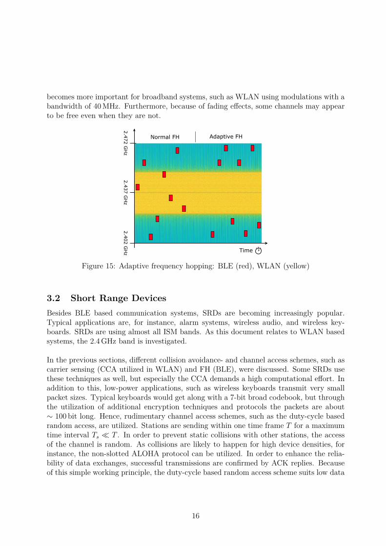
becomes more important for broadband systems, such as WLAN using modulations with abandwidth of 40 MHz. Furthermore, because of fading effects, some channels may appearto be free even when they are not.
Normal FH Adaptive FH
2.4
37 G
Hz
2.4
72 G
Hz
2.4
02 G
Hz Time
Figure 15: Adaptive frequency hopping: BLE (red), WLAN (yellow)
3.2 Short Range DevicesBesides BLE based communication systems, SRDs are becoming increasingly popular.Typical applications are, for instance, alarm systems, wireless audio, and wireless key-boards. SRDs are using almost all ISM bands. As this document relates to WLAN basedsystems, the 2.4 GHz band is investigated.
In the previous sections, different collision avoidance- and channel access schemes, such ascarrier sensing (CCA utilized in WLAN) and FH (BLE), were discussed. Some SRDs usethese techniques as well, but especially the CCA demands a high computational effort. Inaddition to this, low-power applications, such as wireless keyboards transmit very smallpacket sizes. Typical keyboards would get along with a 7-bit broad codebook, but throughthe utilization of additional encryption techniques and protocols the packets are about∼ 100 bit long. Hence, rudimentary channel access schemes, such as the duty-cycle basedrandom access, are utilized. Stations are sending within one time frame T for a maximumtime interval Ts � T . In order to prevent static collisions with other stations, the accessof the channel is random. As collisions are likely to happen for high device densities, forinstance, the non-slotted ALOHA protocol can be utilized. In order to enhance the relia-bility of data exchanges, successful transmissions are confirmed by ACK replies. Becauseof this simple working principle, the duty-cycle based random access scheme suits low data
16

rate applications, such as wireless keyboards [7].
State-of-the-art SRD transceiver chips, such as the CC2500 from Texas Instruments, arecapable of all common modulation types (GFSK, QAM) and channel access schemes (FH,CCA). Depending on the application, an occupied bandwidth (99 %) between 91 kHz and489 kHz at a maximum transmit power of 1 dBm is achieved. Furthermore, RSSI mea-surement functions are implemented. As these kind of integrated chips are highly flexible,SRDs are a serious interference source for WLAN communication systems. Especially low-power applications, using rudimentary channel access schemes, neglecting carrier sensing,presumably affect data exchanges extensively. In addition to this, the transmit power ishigh enough to perturb WLAN receivers close to SRDs.
3.3 Microwave OvensThe widespread use of microwave ovens, for instance, in hospital environments affectsWLAN systems operating in the 2.4 GHz ISM band. As microwave ovens usually havea high power level, compared to other communication standards, they can be detectedeasily. The spectrum of microwave ovens spreads over a wide frequency range for long timeintervals. It is possible to describe the emission characteristics by a narrowband signalwith a bandwidth smaller than 1 MHz and a center frequency of 2.45 GHz. The broadbandspectrum is modeled by significant variations of the center frequency. The radiation patterncan be approximated isotropic with a maximum effective isotropic radiated power (EIRP)level up to 33 dBm, while the mean EIRP is about 5 dBm. Furthermore, the periodicallyemitted RF power depends on several individual device characteristics, such as type, load,and make of the oven.[8].
Type Emission patternTransformer type emits once per AC power cycle,
every 20 msSwitching type emits twice per AC power cycle,
every 10 msInverter type 1 emits once per inverter switching-
cycle typically, every 35 µsInverter type 2 emits twice per inverter switching-
cycle typically, every 17.5 µs
Table 2: Switching characteristics of microwave ovens depending on power supply realiza-tion [8]
17

As the emission pattern strongly depends on the type of the implemented power supply,Table 2 indicates some examples describing the time periodic behavior for different real-izations. Obviously, the radiation pattern for the first two types extends over long timeintervals and for the inverter types over short times, but the off-time is also much shorter.Hence, if the collision avoidance of a WLAN system would detect a microwave oven burstand no PER occurs, still the throughput would be decreased. As a consequence of theseproperties, it is clear that the throughput as well as the PER of WLAN systems may suffersignificantly from this type of interference.
3.4 Radar SystemsUntil now, interference sources of the 2.4 GHz ISM band have been discussed. But the5 GHz band also suffers from perturbations caused, for instance, by weather radar systems.Radar signals are typically very short duration pulses. As no specific timing constraints,such as IFSs, have to be fulfilled it is a challenging task to identify such signals.
Refering to ETSI EN 301 893 V2.1.1 (Annex D), radar signals can be described by differentpatterns [9]. The short pulses are sent periodically within one burst (L), demonstrated inFigure 16. Typical pulse width parameters are between 0.5 µs and 30 µs.
Burst (L)
Time
Figure 16: Example of a radar pattern
In order to mitigate such interferers, the dynamic frequency selection scheme has beenimplemented for WLAN systems working in the 5 GHz band. This technique forces anaccess point to change the transmit channel randomly if a radar signal is detected by theCCA. Consequently, the data transfer between two stations is interrupted during thischange. Especially wrongly detected events identified as radar signals cause a downgradeof the throughput. Furthermore, not all channels utilize the dynamic frequency selectionscheme, i.e., channel 36. Therefore, radar signals can influence WLAN communicationsystems considerably.
18

References[1] IEEE Standards Association, IEEE Std 802.11, 2016. Part 11: Wireless LAN Medium
Access Control (MAC) and Physical Layer (PHY) Specifications. 1, 7, 11
[2] Matthew Gast. 802.11 Wireless Networks: The Definitive Guide. O’Reilly, Sebastopol,Canada, 2002. 1, 2, 3, 4, 6, 7
[3] Travis F. Collins, Robin Getz, Di Pu, Alexander M. Wyglinski. Software-Defined Radiofor Engineers. Artech House, 2018. 8
[4] Keysight Technologies http://rfmw.em.keysight.com/wireless/helpfiles/89600b/webhelp/subsystems/wlan-ofdm/Content/ofdm_80211-overview.htm 10
[5] Timothy M. Schmidl, Donald C. Cox. Robust Frequency and Timing Synchronizationfor OFDM. IEEE Trans. Commun., Vol 45, No. 12, December 1997. 10
[6] Robin Heydon. Bluetooth Low Energy: The Developers Handbook. Prentice Hall, 2013.14, 15
[7] IMST GmbH, 2012. Channel Access Rules for SRDs. https://www.bundesnetzagentur.de/SharedDocs/Downloads/DE/Sachgebiete/Telekommunikation/Unternehmen_Institutionen/Koexistenzstudie_EN.pdf?__blob=publicationFile&v=2 17
[8] Youping Zhao, Brian G. Agee, Jeffrey H. Reed. Simulation and Measurement of Mi-crowave Oven Leakage for 802.11 WLAN Interference Management. IEEE Int. Sym-posium on Microwave, Antenna, Propagation and EMC Technologies for WirelessCommunications Proceedings, 2005. 17
[9] Harmonised European Standard. ETSI EN 301 893 V2.1.1, 5 GHz RLAN; HarmonisedStandard covering the essential requirements of article 3.2 of Directive 2014/53/EU,2017. 18
19