Embed Size (px)
Citation preview
Service Source
K
Workgroup Server 9150
Workgroup Server 9150Workgroup Server 9150/120
Service Source
K
Basics
Workgroup Server 9150
Basics Rear Panel Connectors - 1
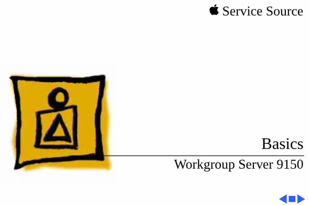
Rear Panel Connectors
Sound Out
Sound In
Sound In Left
ADB
Sound In Right
PrinterModem
EthernetSCSI DB-15 Video
Basics Logic Board Connectors - 2
Logic Board Connectors
Note:
The order of the cache and ROM SIMMs will vary according to the manufacturing date of the logic board. Be sure to correctly identify the cache SIMM, which has four chips on both sides, and remove it before returning the logic board to Apple for repair. Do NOT remove the ROM SIMM before returning the logic board.
Basics Logic Board Connectors - 3
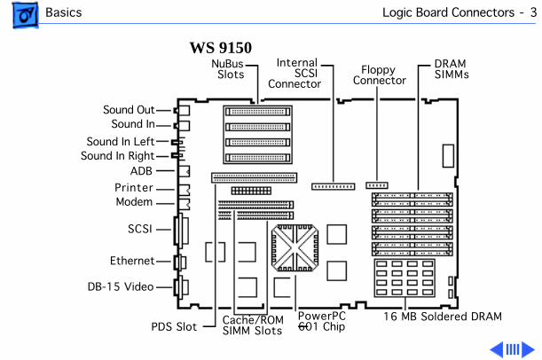
WS 9150
PDS Slot
DB-15 Video
Ethernet
SCSI
ModemPrinter
ADBSound In RightSound In Left
Sound InSound Out
NuBusSlots
Internal SCSIConnector
Floppy Connector
DRAMSIMMs
Cache/ROMSIMM Slots
PowerPC601 Chip
16 MB Soldered DRAM
Basics Logic Board Connectors - 4
Note:
The order of the cache and ROM SIMMs will vary according to the manufacturing date of the logic board. Be sure to correctly identify the cache SIMM, which has four chips on both sides, and remove it before returning the logic board to Apple for repair. Do NOT remove the ROM SIMM before returning the logic board.
Basics Logic Board Connectors - 5
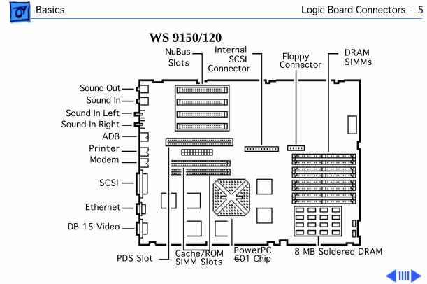
WS 9150/120
Sound OutSound In
Sound In LeftSound In Right
ADBPrinterModem
SCSI
Ethernet
DB-15 Video
NuBus Slots
PDS Slot
Internal SCSIConnector
FloppyConnector
DRAMSIMMs
Cache/ROMSIMM Slots
PowerPC601 Chip
8 MB Soldered DRAM
Basics Logic Board Connectors - 6
Important:
The WS 9150/120 logic board has a thermoelectric cooling device that attaches directly to the microprocessor's heatsink. You can identify this cooling device by the black and red wires that run to the right of the heatsink and plug into the logic board via a keyed connector. This device is not a serviceable item. Do not unplug this device or you may damage the logic board. Also note that the order of the cache and ROM SIMMs may vary. Be sure to correctly identify the cache SIMM and remove it before returning the logic board to Apple for repair. Do NOT remove the ROM SIMM before returning the logic board.
Basics RAID Information - 7
RAID Information
Apple RAID Software
Apple RAID (Redundant Array of Independent Disks) software protects data from loss during a disk failure and enhances the speed of data storage and retrieval. It is available for all Power Macintosh Workgroup servers.
Data protection is achieved through disk mirroring, a data storage scheme in which identical data is stored on two different disks. Apple RAID can also be configured for disk striping, a data storage scheme in which successive units of data are transferred to several disks at one time.
Basics RAID Information - 8
If you plan to install the Apple RAID software on an existing Power Macintosh Workgroup Server, or if you are reinitializing an existing Apple RAID drive, keep in the mind the following:
• If you wish to use your server’s startup disk for Apple RAID, do not install the Apple RAID program on your startup disk until you have initialized and set up new volumes on that disk. Before you initialize the startup disk, backup all valuable data.
• You must reinitialize all disks on which you will use Apple RAID volumes. Initializing with Apple RAID removes all data, so be sure to backup your disks first.
Basics RAID Information - 9
• The Apple RAID CD contains the facilities to reinstall your system software. However, if you have made any customizations to your system files, such as adding extension files, control panels, or preference files, then back up your system files now. Back them up in such a way that you can restore your system files separately from the non-system files on your disk. You will later restore your system files using the backup copy rather than the System Installer on the RAID CD, so that you preserve your system customizations.
• Apple HD SC Setup does not recognize Apple RAID volumes. If you want to remove or resize volumes on Apple RAID disks, use the Apple RAID program.
Service Source
K
Specifications
Workgroup Server 9150
Specifications Processor - 1
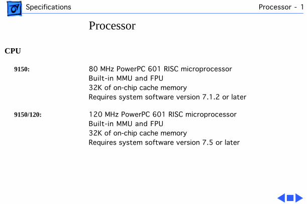
Processor
CPU
9150:
80 MHz PowerPC 601 RISC microprocessor Built-in MMU and FPU32K of on-chip cache memoryRequires system software version 7.1.2 or later
9150/120:
120 MHz PowerPC 601 RISC microprocessor Built-in MMU and FPU32K of on-chip cache memoryRequires system software version 7.5 or later
Specifications Memory - 2
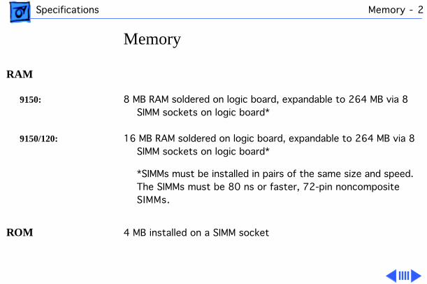
Memory
RAM
9150:
8 MB RAM soldered on logic board, expandable to 264 MB via 8 SIMM sockets on logic board*
9150/120:
16 MB RAM soldered on logic board, expandable to 264 MB via 8 SIMM sockets on logic board*
*SIMMs must be installed in pairs of the same size and speed. The SIMMs must be 80 ns or faster, 72-pin noncomposite SIMMs.
ROM
4 MB installed on a SIMM socket

Specifications Memory - 3
VRAM
None; DRAM video support provided on logic board
Cache
9150:
32K on-chip cache; 512K level 2 cache SIMM
9150/120:
32K on-chip cache; 1 MB level 2 cache SIMM
Clock/Calendar
CMOS custom chip with long-life lithium battery
Specifications Disk Storage - 4
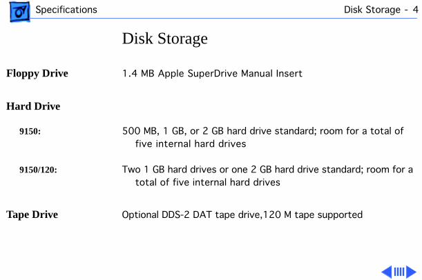
Disk Storage
Floppy Drive
1.4 MB Apple SuperDrive Manual Insert
Hard Drive
9150:
500 MB, 1 GB, or 2 GB hard drive standard; room for a total of five internal hard drives
9150/120:
Two 1 GB hard drives or one 2 GB hard drive standard; room for a total of five internal hard drives
Tape Drive
Optional DDS-2 DAT tape drive,120 M tape supported
Specifications Disk Storage - 5
CD-ROM Drive
9150:
Internal AppleCD 300 Plus CD-ROM drive standard
9150/120:
Internal AppleCD 600 CD-ROM drive standard
Specifications I/O Interfaces - 6
I/O Interfaces
SCSI
One SCSI port; DB-25 connector Supports maximum of seven internal and seven external SCSI
devices
Serial
Two RS-232/RS-422 LocalTalk/GeoPort serial ports; mini DIN-9 connectors (backward compatible with mini DIN-8 connectors)
Apple Desktop Bus
One Apple Desktop Bus (ADB) port; mini-Din-4 connectorMaximum power draw 500 mA; maximum of three devices total
Ethernet
One Ethernet port; AAUI-15 connector
Specifications I/O Interfaces - 7
Expansion Slot
One Power Macintosh video slot; 182-pin connector(Terminator card
must
be installed)
NuBus
Four slots support long or short expansion cards; 96-pin Euro-DIN connectors
Video
One DB-15 DRAM-based video port on logic board

Specifications I/O Interfaces - 8
Sound
8-bit stereo input; 16-bit stereo outputSample rates of 48, 44.1, 24, and 22.05 kHzInput/output line level: 1 V peak-to-peakInput/output signal-to-noise ratio (SNR): 82 dB with no audible
discrete tonesBandwidth: 20 Hz–20 kHz ± 2 dB) at 44.100 kHz sample rate
THD+N (total harmonic distortion plus noise): less than 0.05%, measured 20Hz–20 kHz with a 1-Vrms sine wave input
Specifications I/O Devices - 9
I/O Devices
Keyboard
Standard, extended, or adjustable keyboardKeyboard draws 25–80 mA, depending on model of keyboard
Mouse
ADB Mouse II; Draws up to 10 mA
Microphone
Electret, omnidirectional; output voltage is 4 mV, peak to peak, at normal value; does not use Apple PlainTalk microphone
Specifications Video Display - 10
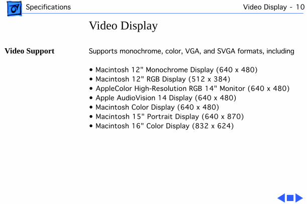
Video Display
Video Support
Supports monochrome, color, VGA, and SVGA formats, including
• Macintosh 12" Monochrome Display (640 x 480)• Macintosh 12" RGB Display (512 x 384)• AppleColor High-Resolution RGB 14" Monitor (640 x 480)• Apple AudioVision 14 Display (640 x 480)• Macintosh Color Display (640 x 480) • Macintosh 15" Portrait Display (640 x 870) • Macintosh 16" Color Display (832 x 624)
Specifications Electrical - 11
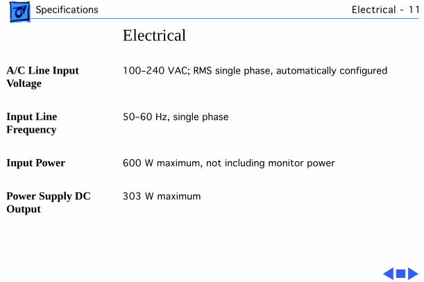
Electrical
A/C Line Input Voltage
100–240 VAC; RMS single phase, automatically configured
Input Line Frequency
50–60 Hz, single phase
Input Power
600 W maximum, not including monitor power
Power Supply DC Output
303 W maximum
Specifications Physical - 12
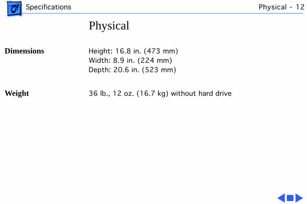
Physical
Dimensions
Height: 16.8 in. (473 mm)Width: 8.9 in. (224 mm)Depth: 20.6 in. (523 mm)
Weight
36 lb., 12 oz. (16.7 kg) without hard drive
Specifications Environmental - 13
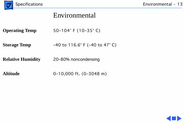
Environmental
Operating Temp
50–104° F (10–35° C)
Storage Temp
–40 to 116.6° F (–40 to 47° C)
Relative Humidity
20–80% noncondensing
Altitude
0–10,000 ft. (0–3048 m)
Service Source
K
Troubleshooting
Workgroup Server 9150
Troubleshooting General - 1
General
The Symptom Charts included in this chapter will help you diagnose specific symptoms related to your product. Because cures are listed on the charts in the order of most likely solution, try the first cure first. Verify whether or not the product continues to exhibit the symptom. If the symptom persists, try the next cure. (Note: If you have replaced a module, reinstall the original module before you proceed to the next cure.)
If you are not sure what the problem is, or if the Symptom Charts do not resolve the problem, refer to the Flowchart for the product family.
For additional assistance, contact Apple Technical Support.
Troubleshooting Cleaning Procedure for Card Connectors - 2
Cleaning Procedure for Card Connectors
A small number of cards for the Workgroup Server 9150 may contain residue on the gold edge connector pins, which may cause a variety of intermittent symptoms.
To correct the problem, inspect the connector pins with a magnifying glass. If you find residue, use a pencil eraser to gently clean the pins.
Troubleshooting Symptom Charts/Power Supply - 3
Symptom Charts
Power Supply
System does not power up
1 Reset logic board. (Refer to Additional Procedures.)2 Reseat ROM, RAM, and cache SIMMs, and reseat terminator
card.3 Replace power supply.4 Replace logic board.
Troubleshooting Symptom Charts/Error Chords - 4
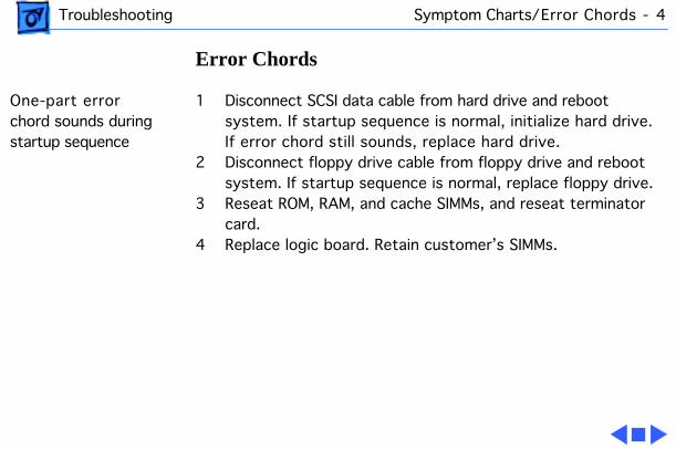
Error Chords
One-part error chord sounds during startup sequence
1 Disconnect SCSI data cable from hard drive and reboot system. If startup sequence is normal, initialize hard drive. If error chord still sounds, replace hard drive.
2 Disconnect floppy drive cable from floppy drive and reboot system. If startup sequence is normal, replace floppy drive.
3 Reseat ROM, RAM, and cache SIMMs, and reseat terminator card.
4 Replace logic board. Retain customer’s SIMMs.
Troubleshooting Symptom Charts/System - 5
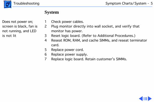
System
Does not power on; screen is black, fan is not running, and LED is not lit
1 Check power cables.2 Plug monitor directly into wall socket, and verify that
monitor has power.3 Reset logic board. (Refer to Additional Procedures.)4 Reseat ROM, RAM, and cache SIMMs, and reseat terminator
card.5 Replace power cord.6 Replace power supply.7 Replace logic board. Retain customer’s SIMMs.
Troubleshooting Symptom Charts/System
(Continued)
- 6
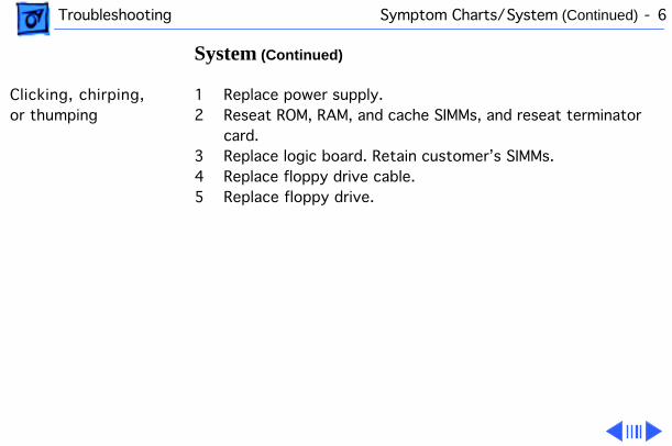
System
(Continued)
Clicking, chirping, or thumping
1 Replace power supply.2 Reseat ROM, RAM, and cache SIMMs, and reseat terminator
card.3 Replace logic board. Retain customer’s SIMMs.4 Replace floppy drive cable.5 Replace floppy drive.
Troubleshooting Symptom Charts/System
(Continued)
- 7
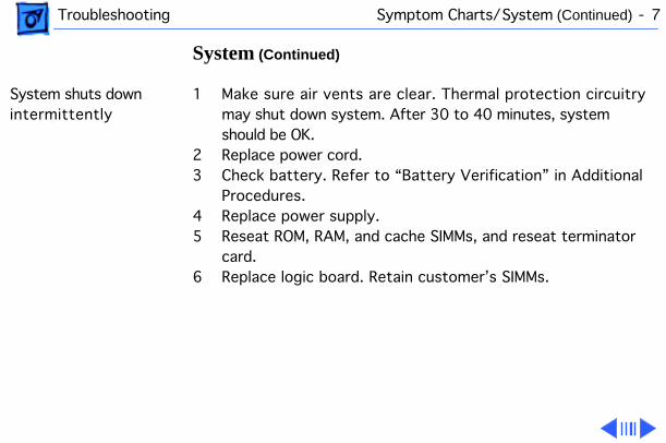
System
(Continued)
System shuts down intermittently
1 Make sure air vents are clear. Thermal protection circuitry may shut down system. After 30 to 40 minutes, system should be OK.
2 Replace power cord.3 Check battery. Refer to “Battery Verification” in Additional
Procedures.4 Replace power supply.5 Reseat ROM, RAM, and cache SIMMs, and reseat terminator
card.6 Replace logic board. Retain customer’s SIMMs.
Troubleshooting Symptom Charts/System
(Continued)
- 8
System
(Continued)
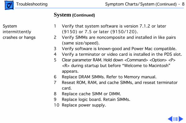
System intermittently crashes or hangs
1 Verify that system software is version 7.1.2 or later (9150) or 7.5 or later (9150/120).
2 Verify SIMMs are noncomposite and installed in like pairs (same size/speed).
3 Verify software is known-good and Power Mac compatible.4 Verify a terminator or video card is installed in the PDS slot.5 Clear parameter RAM. Hold down <Command> <Option> <P>
<R> during startup but before “Welcome to Macintosh” appears.
6 Replace DRAM SIMMs. Refer to Memory manual.7 Reseat ROM, RAM, and cache SIMMs, and reseat terminator
card.8 Replace cache SIMM or DIMM.9 Replace logic board. Retain SIMMs.10 Replace power supply.
Troubleshooting Symptom Charts/System
(Continued)
- 9
System
(Continued)
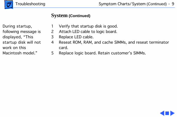
During startup, following message is displayed, “This startup disk will not work on this Macintosh model.”
1 Verify that startup disk is good.2 Attach LED cable to logic board.3 Replace LED cable.4 Reseat ROM, RAM, and cache SIMMs, and reseat terminator
card.5 Replace logic board. Retain customer’s SIMMs.
Troubleshooting Symptom Charts/Video - 10
Video
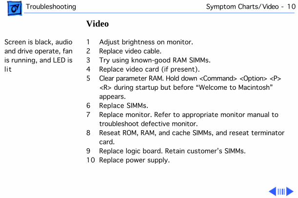
Screen is black, audio and drive operate, fan is running, and LED is l it
1 Adjust brightness on monitor.2 Replace video cable.3 Try using known-good RAM SIMMs.4 Replace video card (if present).5 Clear parameter RAM. Hold down <Command> <Option> <P>
<R> during startup but before “Welcome to Macintosh” appears.
6 Replace SIMMs.7 Replace monitor. Refer to appropriate monitor manual to
troubleshoot defective monitor.8 Reseat ROM, RAM, and cache SIMMs, and reseat terminator
card.9 Replace logic board. Retain customer’s SIMMs.10 Replace power supply.
Troubleshooting Symptom Charts/Video
(Continued)
- 11
Video
(Continued)
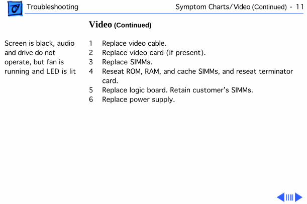
Screen is black, audio and drive do not operate, but fan is running and LED is lit
1 Replace video cable.2 Replace video card (if present).3 Replace SIMMs. 4 Reseat ROM, RAM, and cache SIMMs, and reseat terminator
card.5 Replace logic board. Retain customer’s SIMMs.6 Replace power supply.
Troubleshooting Symptom Charts/Video
(Continued)
- 12
Video
(Continued)
Partial or whole screen is bright and audio is present, but no video information is visible
1 Replace video cable.2 Replace video card (if present).3 Clear parameter RAM. Hold down <Command> <Option> <P>
<R> during startup but before “Welcome to Macintosh” appears.
4 Replace monitor. Refer to appropriate monitor manual to troubleshoot defective monitor.
5 Reseat ROM, RAM, and cache SIMMs, and reseat terminator card.
6 Replace logic board. Retain customer’s SIMMs.
Troubleshooting Symptom Charts/Floppy Drive - 13
Floppy Drive
Internal floppy drive does not operate
1 Replace disk with known-good floppy disk.2 Replace floppy drive cable.3 Replace floppy drive.4 Reseat ROM, RAM, and cache SIMMs, and reseat terminator
card.5 Replace logic board. Retain customer’s SIMMs.6 Replace power supply.
Troubleshooting Symptom Charts/Floppy Drive
(Continued)
- 14
Floppy Drive
(Continued)
During system startup, disk ejects; display shows icon with blinking “X”
1 Replace disk with known-good system disk.2 Clear parameter RAM. Hold down <Command> <Option> <P>
<R> during startup but before “Welcome to Macintosh” appears.
3 Replace floppy drive cable.4 Replace floppy drive.5 Reseat ROM, RAM, and cache SIMMs, and reseat terminator
card.6 Replace logic board. Retain customer’s SIMMs.
Troubleshooting Symptom Charts/Floppy Drive
(Continued)
- 15
Floppy Drive
(Continued)
Does not eject disk 1 Switch off computer. Hold mouse button down while you switch computer on.
2 Replace floppy drive cable.3 Replace floppy drive.4 Reseat ROM, RAM, and cache SIMMs, and reseat terminator
card.5 Replace logic board. Retain customer’s SIMMs.
Attempts to eject disk, but doesn’t
1 Push disk completely in.2 Reseat floppy drive bezel and drive so bezel slot aligns
correctly with drive.3 Eject disk manually.4 Replace floppy drive.
Troubleshooting Symptom Charts/Floppy Drive
(Continued)
- 16
Floppy Drive
(Continued)
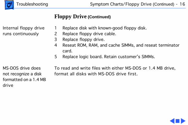
Internal floppy drive runs continuously
1 Replace disk with known-good floppy disk.2 Replace floppy drive cable.3 Replace floppy drive.4 Reseat ROM, RAM, and cache SIMMs, and reseat terminator
card.5 Replace logic board. Retain customer’s SIMMs.
MS-DOS drive does not recognize a disk formatted on a 1.4 MB drive
To read and write files with either MS-DOS or 1.4 MB drive, format all disks with MS-DOS drive first.
Troubleshooting Symptom Charts/Hard Drive - 17
Hard Drive
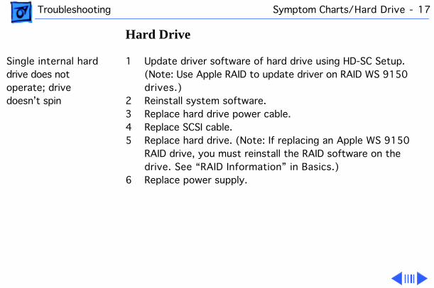
Single internal hard drive does not operate; drive doesn’t spin
1 Update driver software of hard drive using HD-SC Setup. (Note: Use Apple RAID to update driver on RAID WS 9150 drives.)
2 Reinstall system software.3 Replace hard drive power cable.4 Replace SCSI cable.5 Replace hard drive. (Note: If replacing an Apple WS 9150
RAID drive, you must reinstall the RAID software on the drive. See “RAID Information” in Basics.)
6 Replace power supply.
Troubleshooting Symptom Charts/Hard drive
(Continued)
- 18
Hard drive
(Continued)
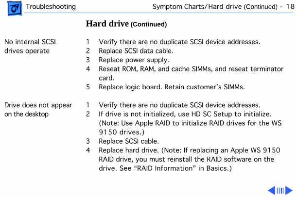
No internal SCSI drives operate
1 Verify there are no duplicate SCSI device addresses.2 Replace SCSI data cable.3 Replace power supply.4 Reseat ROM, RAM, and cache SIMMs, and reseat terminator
card.5 Replace logic board. Retain customer’s SIMMs.
Drive does not appear on the desktop
1 Verify there are no duplicate SCSI device addresses.2 If drive is not initialized, use HD SC Setup to initialize.
(Note: Use Apple RAID to initialize RAID drives for the WS 9150 drives.)
3 Replace SCSI cable.4 Replace hard drive. (Note: If replacing an Apple WS 9150
RAID drive, you must reinstall the RAID software on the drive. See “RAID Information” in Basics.)
Troubleshooting Symptom Charts/Hard Drive
(Continued)
- 19
Hard Drive
(Continued)
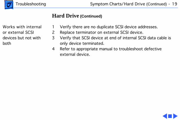
Works with internal or external SCSI devices but not with both
1 Verify there are no duplicate SCSI device addresses.2 Replace terminator on external SCSI device.3 Verify that SCSI device at end of internal SCSI data cable is
only device terminated.4 Refer to appropriate manual to troubleshoot defective
external device.
Troubleshooting Symptom Charts/Peripherals - 20
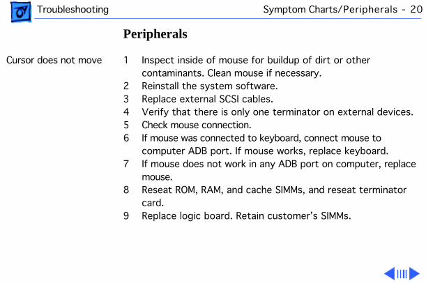
Peripherals
Cursor does not move 1 Inspect inside of mouse for buildup of dirt or other contaminants. Clean mouse if necessary.
2 Reinstall the system software.3 Replace external SCSI cables.4 Verify that there is only one terminator on external devices.5 Check mouse connection.6 If mouse was connected to keyboard, connect mouse to
computer ADB port. If mouse works, replace keyboard.7 If mouse does not work in any ADB port on computer, replace
mouse.8 Reseat ROM, RAM, and cache SIMMs, and reseat terminator
card.9 Replace logic board. Retain customer’s SIMMs.
Troubleshooting Symptom Charts/Peripherals
(Continued)
- 21
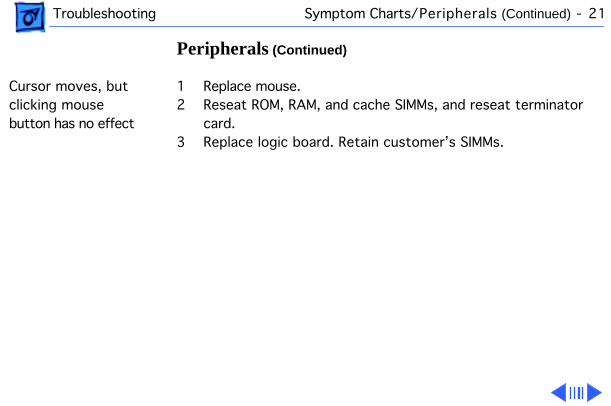
Peripherals
(Continued)
Cursor moves, but clicking mouse button has no effect
1 Replace mouse.2 Reseat ROM, RAM, and cache SIMMs, and reseat terminator
card.3 Replace logic board. Retain customer’s SIMMs.
Troubleshooting Symptom Charts/Peripherals
(Continued)
- 22
Peripherals
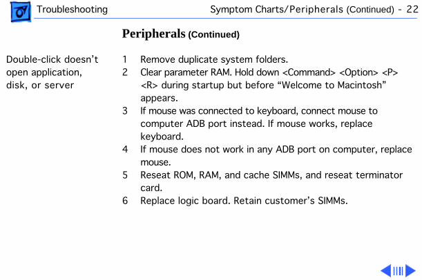
(Continued)
Double-click doesn’t open application, disk, or server
1 Remove duplicate system folders.2 Clear parameter RAM. Hold down <Command> <Option> <P>
<R> during startup but before “Welcome to Macintosh” appears.
3 If mouse was connected to keyboard, connect mouse to computer ADB port instead. If mouse works, replace keyboard.
4 If mouse does not work in any ADB port on computer, replace mouse.
5 Reseat ROM, RAM, and cache SIMMs, and reseat terminator card.
6 Replace logic board. Retain customer’s SIMMs.
Troubleshooting Symptom Charts/Peripherals
(Continued)
- 23
Peripherals
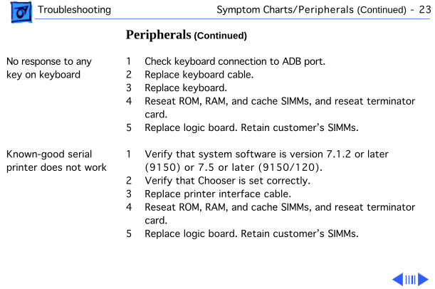
(Continued)
No response to any key on keyboard
1 Check keyboard connection to ADB port.2 Replace keyboard cable.3 Replace keyboard.4 Reseat ROM, RAM, and cache SIMMs, and reseat terminator
card.5 Replace logic board. Retain customer’s SIMMs.
Known-good serial printer does not work
1 Verify that system software is version 7.1.2 or later (9150) or 7.5 or later (9150/120).
2 Verify that Chooser is set correctly.3 Replace printer interface cable.4 Reseat ROM, RAM, and cache SIMMs, and reseat terminator
card.5 Replace logic board. Retain customer’s SIMMs.
Troubleshooting Symptom Charts/Peripherals
(Continued)
- 24
Peripherals
(Continued)
Known-good network printer does not print
1 Verify that system software is version 7.1.2 or later (9150) or 7.5 or later (9150/120).
2 Verify that Chooser is set correctly.3 Reseat ROM, RAM, and cache SIMMs, and reseat terminator
card.4 Replace logic board. Retain customer’s SIMMs.
Troubleshooting Symptom Charts/Miscellaneous - 25
Miscellaneous
No sound from speaker
1 Verify that volume setting in Control Panel is 1 or above.2 Replace speaker.3 Reseat ROM, RAM, and cache SIMMs, and reseat terminator
card.4 Replace logic board. Retain customer’s SIMMs.
About This Macintosh reports more memory than is installed
1 Check to see if virtual memory is turned on (which will cause the system to report more memory).
2 Verify that RAM SIMMs are installed in matching pairs (same size and speed).
3 Replace RAM SIMMs.
Troubleshooting Symptom Charts/Miscellaneous
(Continued)
- 26
Miscellaneous
(Continued)
About This Macintosh reports less memory than is installed
1 Verify that RAM SIMMs are installed in matching pairs (same size and speed).
2 Replace RAM SIMMs.
System hangs, I/O errors, or “mirrors out of sync” errors resulting from SCSI Bus-intensive activity
1 Verify that system software is version 7.1.2 or later (9150) or 7.5 or later (9150/120).
2 Clear parameter RAM. Hold down <Command> <Option> <P> <R> during startup but before “Welcome to Macintosh” appears.
3 Replace the logic board with part number 661-0993 and retain customer’s SIMMs. (Note: This problem occurs only on the 80 MHz version of the WS 9150 and only during periods of heavy SCSI Bus activity (for example, when using backup programs or disk arrays).
Troubleshooting Symptom Charts/CD-ROM Drive - 27
CD-ROM Drive
CD-ROM drive does not accept compact disc
1 Exchange disc.2 Replace CD-ROM drive mechanism.
Macintosh does not display CD-ROM drive icon
1 Verify that CD-ROM software is installed.2 Replace SCSI data cable.3 Replace CD-ROM drive mechanism.
Computer with 600i CD-ROM drive makes stuttering sounds when playing CD+ or CD-R formatted discs or CD-ROM disc won’t mount
Replace CD-ROM drive.
Service Source
K
Take Apart
Workgroup Server 9150
Take Apart Cover - 1
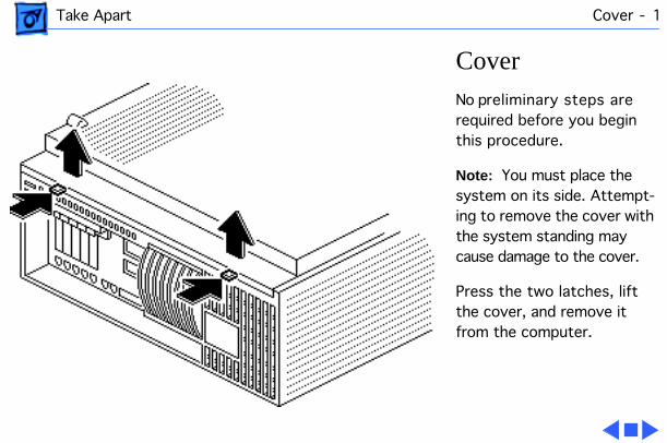
Cover
No preliminary steps are required before you begin this procedure.
Note:
You must place the system on its side. Attempt-ing to remove the cover with the system standing may cause damage to the cover.
Press the two latches, lift the cover, and remove it from the computer.
Take Apart 5-Drive Carrier - 2
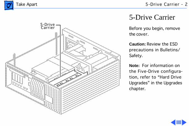
5-Drive Carrier
Before you begin, remove the cover.
Caution:
Review the ESD precautions in Bulletins/Safety.
Note:
For information on the Five-Drive configura-tion, refer to “Hard Drive Upgrades” in the Upgrades chapter.
5-DriveCarrier
Take Apart 5-Drive Carrier - 3
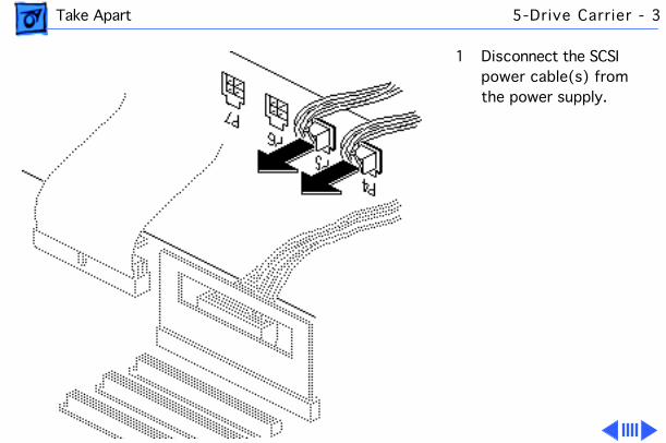
1 Disconnect the SCSI power cable(s) from the power supply.
Take Apart 5-Drive Carrier - 4
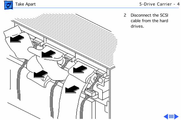
2 Disconnect the SCSI cable from the hard drives.
Take Apart 5-Drive Carrier - 5
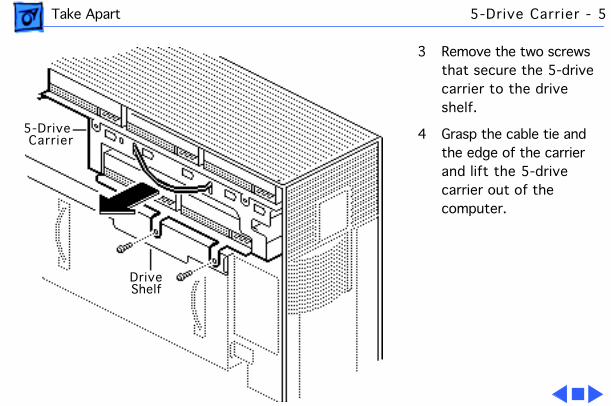
3 Remove the two screws that secure the 5-drive carrier to the drive shelf.
4 Grasp the cable tie and the edge of the carrier and lift the 5-drive carrier out of the computer.
5-DriveCarrier
DriveShelf
Take Apart Drive Shelf - 6
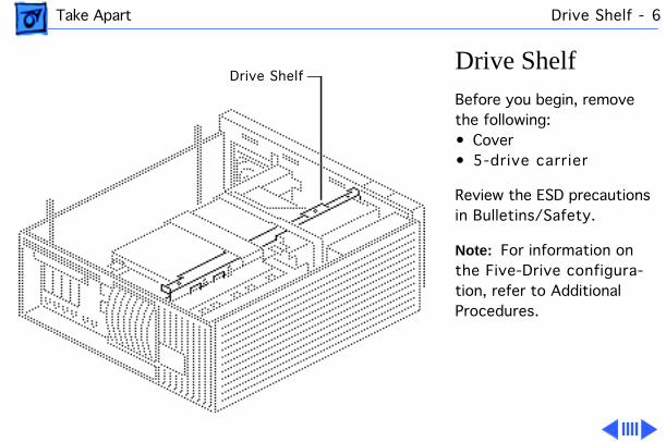
Drive Shelf
Before you begin, remove the following:• Cover• 5-drive carrier
Review the ESD precautions in Bulletins/Safety.
Note:
For information on the Five-Drive configura-tion, refer to Additional Procedures.
Drive Shelf
Take Apart Drive Shelf - 7
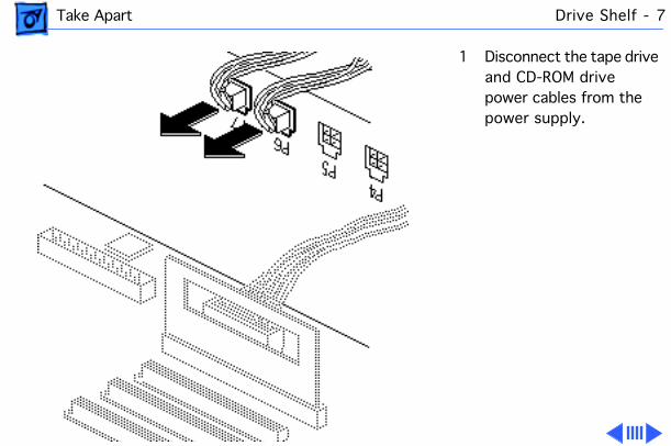
1 Disconnect the tape drive and CD-ROM drive power cables from the power supply.
Take Apart Drive Shelf - 8
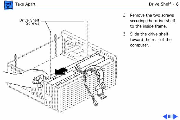
2 Remove the two screws securing the drive shelf to the inside frame.
3 Slide the drive shelf toward the rear of the computer.
Drive ShelfScrews
Take Apart Drive Shelf - 9
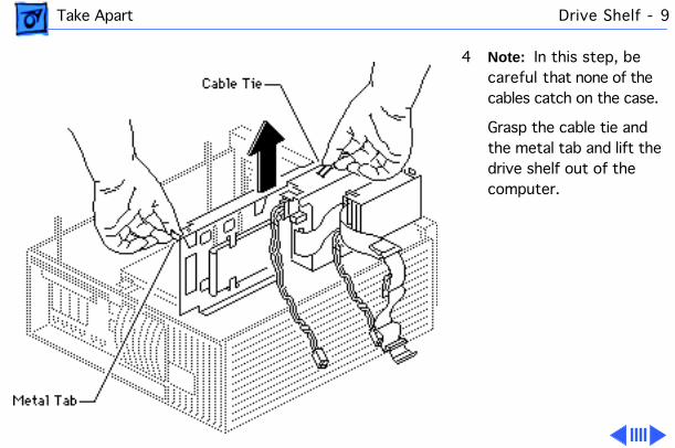
4
Note:
In this step, be careful that none of the cables catch on the case.
Grasp the cable tie and the metal tab and lift the drive shelf out of the computer.
Take Apart Drive Shelf - 10
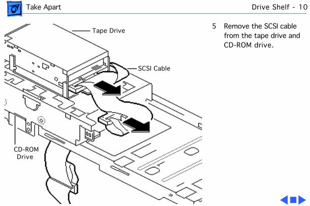
5 Remove the SCSI cable from the tape drive and CD-ROM drive.
Tape Drive
SCSI Cable
CD-ROM Drive
Take Apart Front Panel - 11
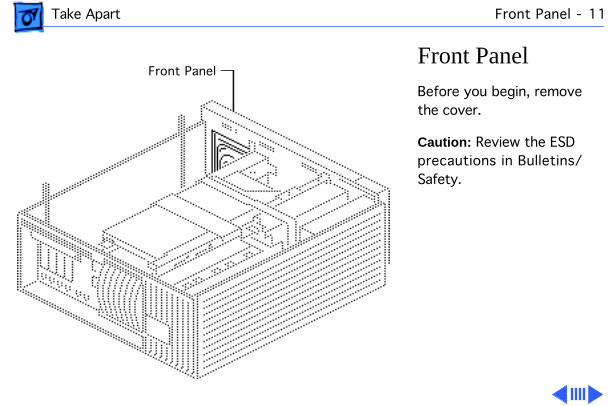
Front Panel
Before you begin, remove the cover.
Caution:
Review the ESD precautions in Bulletins/Safety.
Front Panel
Take Apart Front Panel - 12
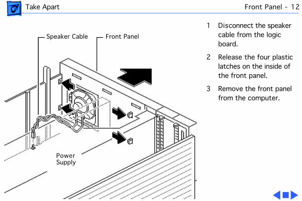
1 Disconnect the speaker cable from the logic board.
2 Release the four plastic latches on the inside of the front panel.
3 Remove the front panel from the computer.
Speaker Cable Front Panel
PowerSupply
Take Apart Speaker - 13
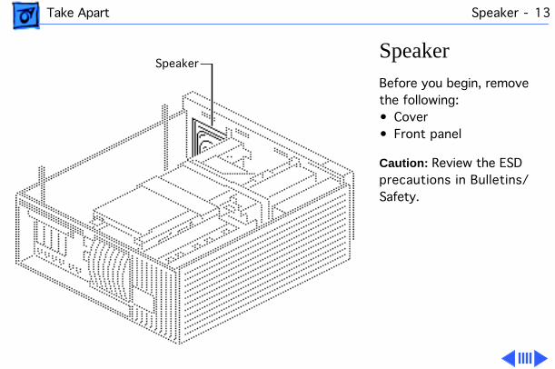
Speaker
Before you begin, remove the following:• Cover• Front panel
Caution:
Review the ESD precautions in Bulletins/Safety.
Speaker
Take Apart Speaker - 14
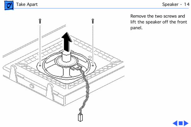
Remove the two screws and lift the speaker off the front panel.
Take Apart Floppy Drive - 15
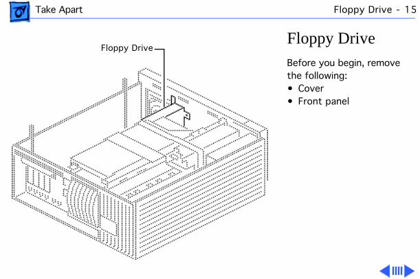
Floppy Drive
Before you begin, remove the following:• Cover• Front panel
Floppy Drive
Take Apart Floppy Drive - 16
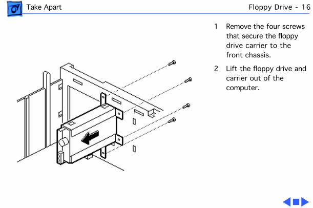
1 Remove the four screws that secure the floppy drive carrier to the front chassis.
2 Lift the floppy drive and carrier out of the computer.
Take Apart Hard Drive - 17
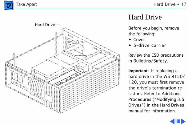
Hard Drive
Before you begin, remove the following:• Cover• 5-drive carrier
Review the ESD precautions in Bulletins/Safety.
Important:
If replacing a hard drive in the WS 9150/120, you must first remove the drive’s termination re-sistors. Refer to Additional Procedures (“Modifying 3.5 Drives”) in the Hard Drives manual for information.
Hard Drive
Take Apart Hard Drive - 18
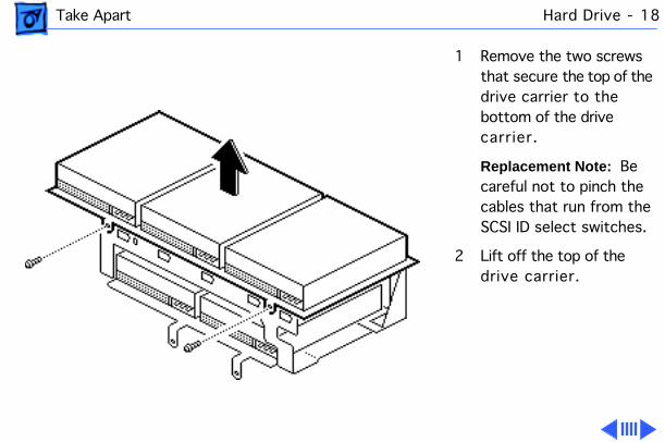
1 Remove the two screws that secure the top of the drive carrier to the bottom of the drive carrier.
Replacement Note:
Be careful not to pinch the cables that run from the SCSI ID select switches.
2 Lift off the top of the drive carrier.
Take Apart Hard Drive - 19
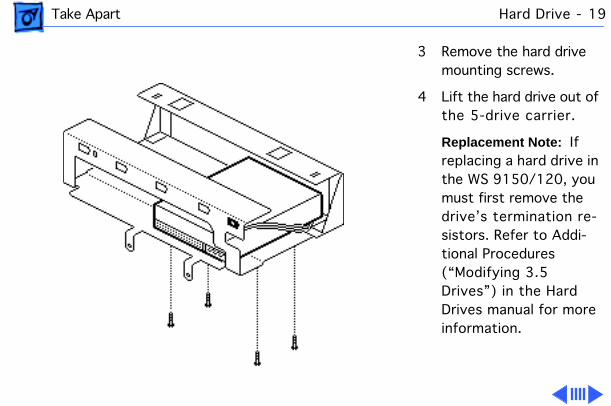
3 Remove the hard drive mounting screws.
4 Lift the hard drive out of the 5-drive carrier.
Replacement Note:
If replacing a hard drive in the WS 9150/120, you must first remove the drive’s termination re-sistors. Refer to Addi-tional Procedures (“Modifying 3.5 Drives”) in the Hard Drives manual for more information.
Take Apart Hard Drive - 20
Replacement Note:
For information on removing the hard drive from the carrier and returning drives, cables, and carriers to Apple, refer to Additional Procedures in the Hard Drives manual.
Take Apart Tape Drive - 21
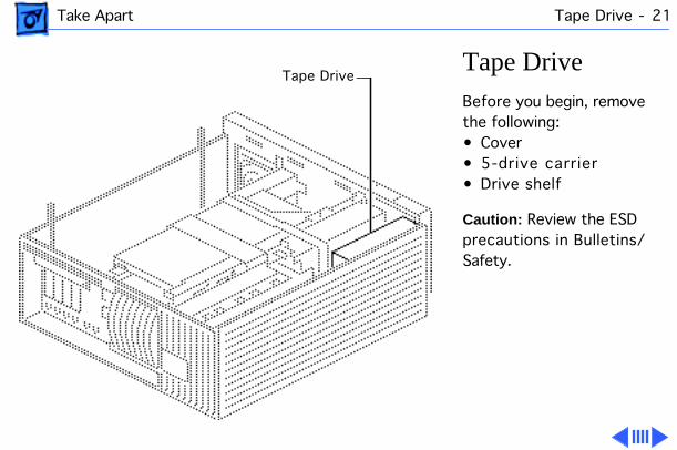
Tape Drive
Before you begin, remove the following:• Cover• 5-drive carrier• Drive shelf
Caution:
Review the ESD precautions in Bulletins/Safety.
Tape Drive
Take Apart Tape Drive - 22
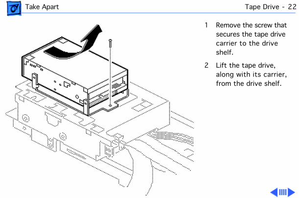
1 Remove the screw that secures the tape drive carrier to the drive shelf.
2 Lift the tape drive, along with its carrier, from the drive shelf.
Take Apart Tape Drive - 23
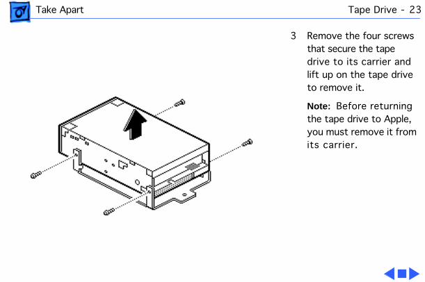
3 Remove the four screws that secure the tape drive to its carrier and lift up on the tape drive to remove it.
Note:
Before returning the tape drive to Apple, you must remove it from its carrier.
Take Apart CD-ROM Drive - 24
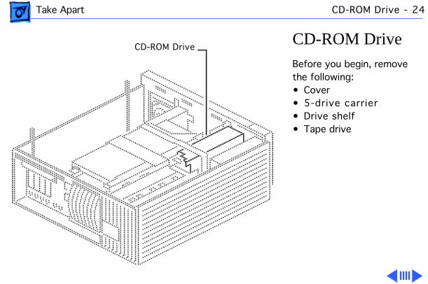
CD-ROM Drive
Before you begin, remove the following:• Cover• 5-drive carrier• Drive shelf• Tape drive
CD-ROM Drive
Take Apart CD-ROM Drive - 25
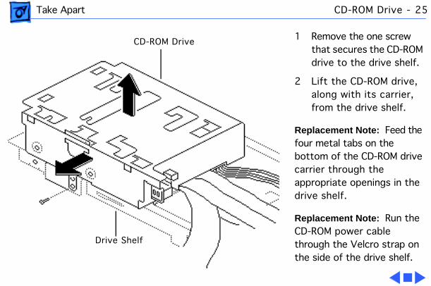
1 Remove the one screw that secures the CD-ROM drive to the drive shelf.
2 Lift the CD-ROM drive, along with its carrier, from the drive shelf.
Replacement Note:
Feed the four metal tabs on the bottom of the CD-ROM drive carrier through the appropriate openings in the drive shelf.
Replacement Note:
Run the CD-ROM power cable through the Velcro strap on the side of the drive shelf.
CD-ROM Drive
Drive Shelf
Take Apart Power Supply - 26
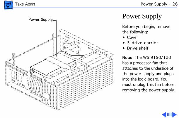
Power Supply
Before you begin, remove the following:• Cover• 5-drive carrier• Drive shelf
Note:
The WS 9150/120 has a processor fan that attaches to the underside of the power supply and plugs into the logic board. You must unplug this fan before removing the power supply.
Power Supply
Take Apart Power Supply - 27
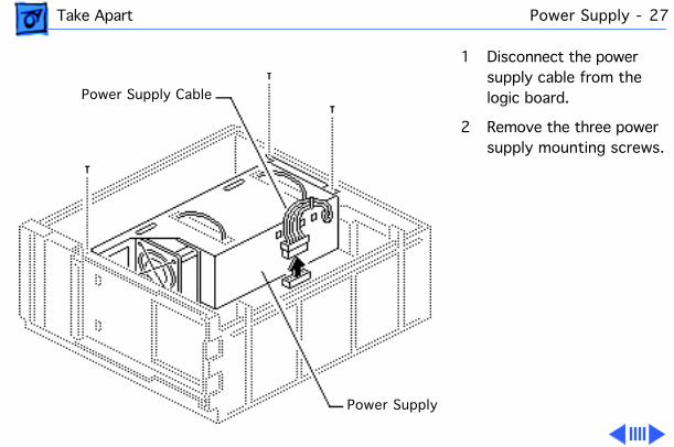
1 Disconnect the power supply cable from the logic board.
2 Remove the three power supply mounting screws.
Power Supply Cable
Power Supply
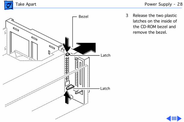
Take Apart Power Supply - 28
3 Release the two plastic latches on the inside of the CD-ROM bezel and remove the bezel.
Bezel
Latch
Latch
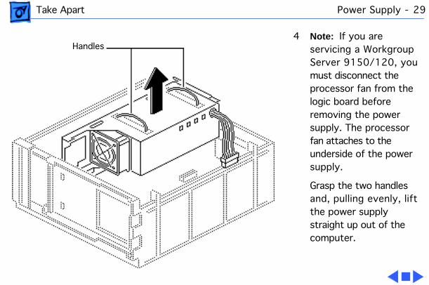
Take Apart Power Supply - 29
4
Note:
If you are servicing a Workgroup Server 9150/120, you must disconnect the processor fan from the logic board before removing the power supply. The processor fan attaches to the underside of the power supply.
Grasp the two handles and, pulling evenly, lift the power supply straight up out of the computer.
Handles
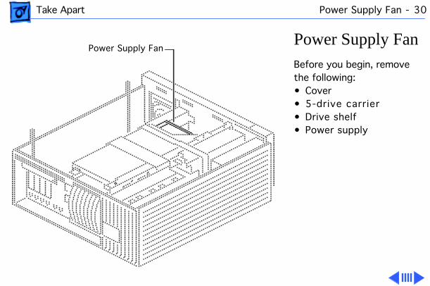
Take Apart Power Supply Fan - 30
Power Supply Fan
Before you begin, remove the following:• Cover• 5-drive carrier• Drive shelf• Power supply
Power Supply Fan
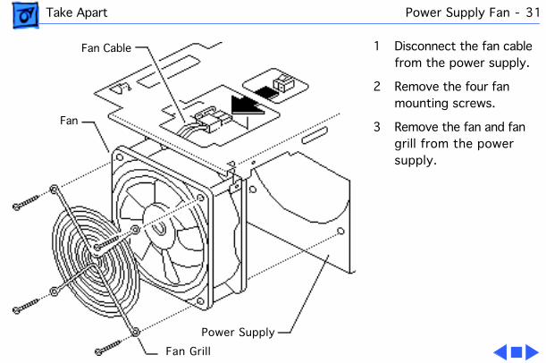
Take Apart Power Supply Fan - 31
1 Disconnect the fan cable from the power supply.
2 Remove the four fan mounting screws.
3 Remove the fan and fan grill from the power supply.
Fan Cable
Fan
Power Supply
Fan Grill
Take Apart Processor Fan - 32
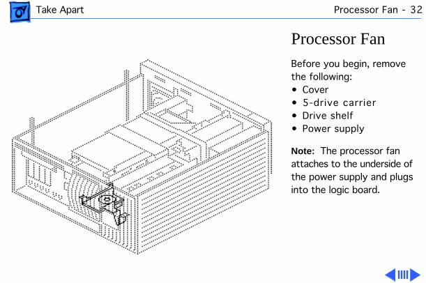
Processor Fan
Before you begin, remove the following:• Cover• 5-drive carrier• Drive shelf• Power supply
Note:
The processor fan attaches to the underside of the power supply and plugs into the logic board.
Ê
Take Apart Processor Fan - 33
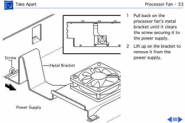
1 Pull back on the processor fan’s metal bracket until it clears the screw securing it to the power supply.
2 Lift up on the bracket to remove it from the power supply.Screw
Power Supply
tal Bracket
Take Apart Processor Fan - 34
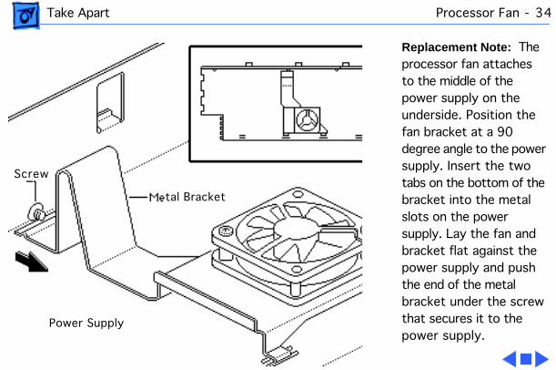
Replacement Note:
The processor fan attaches to the middle of the power supply on the underside. Position the fan bracket at a 90 degree angle to the power supply. Insert the two tabs on the bottom of the bracket into the metal slots on the power supply. Lay the fan and bracket flat against the power supply and push the end of the metal bracket under the screw that secures it to the power supply.
Screw
Power Supply
tal Bracket

Take Apart NuBus Cards - 35
NuBus Cards
Before you begin, remove the cover.
Caution:
Review the ESD precautions in Bulletins/Safety.
Caution:
You must unplug the computer prior to removing or installing NuBus cards. Failure to unplug the computer could cause damage to the logic board and/or cards.
NuBus Card
Take Apart NuBus Cards - 36
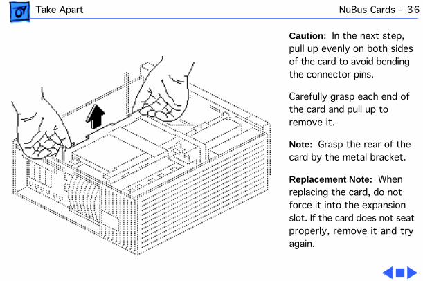
Caution:
In the next step, pull up evenly on both sides of the card to avoid bending the connector pins.
Carefully grasp each end of the card and pull up to remove it.
Note:
Grasp the rear of the card by the metal bracket.
Replacement Note:
When replacing the card, do not force it into the expansion slot. If the card does not seat properly, remove it and try again.
Take Apart Logic Board - 37
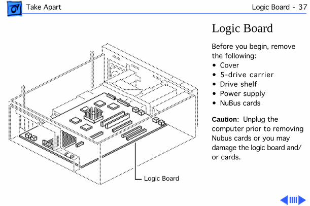
Logic Board
Before you begin, remove the following:• Cover• 5-drive carrier• Drive shelf• Power supply• NuBus cards
Caution:
Unplug the computer prior to removing Nubus cards or you may damage the logic board and/or cards.
Logic BoardLogic Board
Take Apart Logic Board - 38
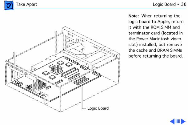
Note:
When returning the logic board to Apple, return it with the ROM SIMM and terminator card (located in the Power Macintosh video slot) installed, but remove the cache and DRAM SIMMs before returning the board.
Logic Board
Take Apart Logic Board - 39
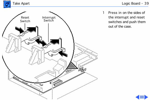
1 Press in on the sides of the interrupt and reset switches and push them out of the case.
ResetSwitch
InterruptSwitch
Take Apart Logic Board - 40
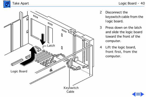
2 Disconnect the keyswitch cable from the l ogic board.
3 Press down on the latch and slide the logic board toward the front of the computer.
4 Lift the logic board, front first, from the computer.
Latch
Logic Board
KeyswitchCable
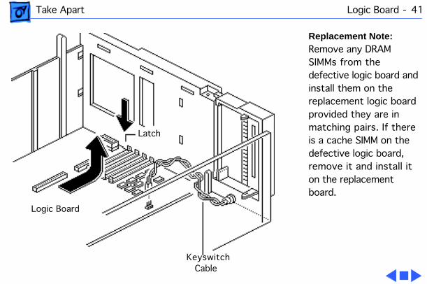
Take Apart Logic Board - 41
Replacement Note:
Remove any DRAM SIMMs from the defective logic board and install them on the replacement logic board provided they are in matching pairs. If there is a cache SIMM on the defective logic board, remove it and install it on the replacement board.
Latch
Logic Board
KeyswitchCable
Service Source
K
Upgrades
Workgroup Server 9150
Upgrades NuBus Cards - 1
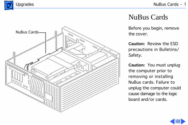
NuBus Cards
Before you begin, remove the cover.
Caution:
Review the ESD precautions in Bulletins/Safety.
Caution:
You must unplug the computer prior to removing or installing NuBus cards. Failure to unplug the computer could cause damage to the logic board and/or cards.
NuBus Cards
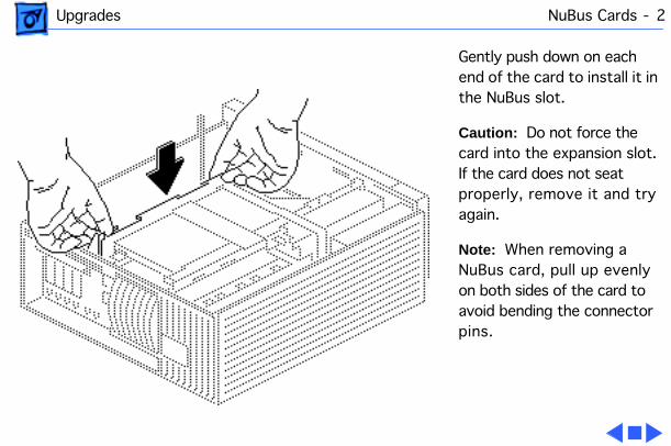
Upgrades NuBus Cards - 2
Gently push down on each end of the card to install it in the NuBus slot.
Caution:
Do not force the card into the expansion slot. If the card does not seat properly, remove it and try again.
Note:
When removing a NuBus card, pull up evenly on both sides of the card to avoid bending the connector pins.
Upgrades Hard Drive Upgrades - 3
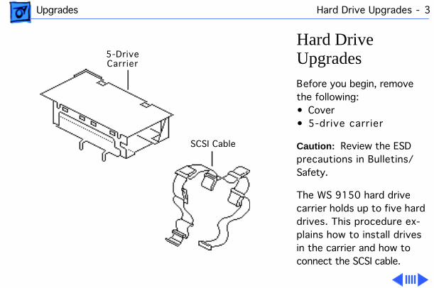
Hard Drive Upgrades
Before you begin, remove the following:• Cover• 5-drive carrier
Caution:
Review the ESD precautions in Bulletins/Safety.
The WS 9150 hard drive carrier holds up to five hard drives. This procedure ex-plains how to install drives in the carrier and how to connect the SCSI cable.
5-Drive Carrier
SCSI Cable
Upgrades Hard Drive Upgrades - 4
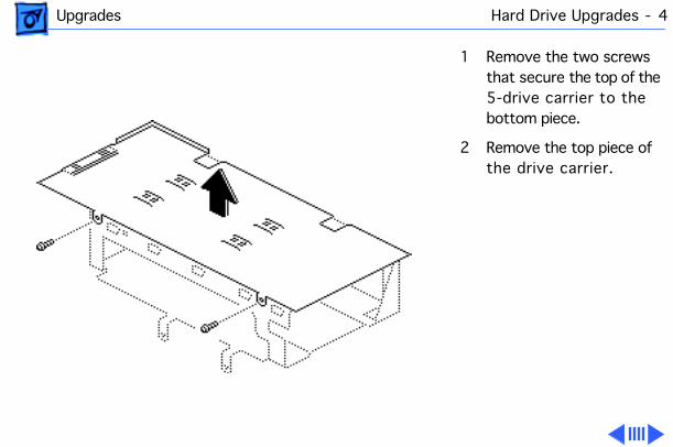
1 Remove the two screws that secure the top of the 5-drive carrier to the bottom piece.
2 Remove the top piece of the drive carrier.
Upgrades Hard Drive Upgrades - 5
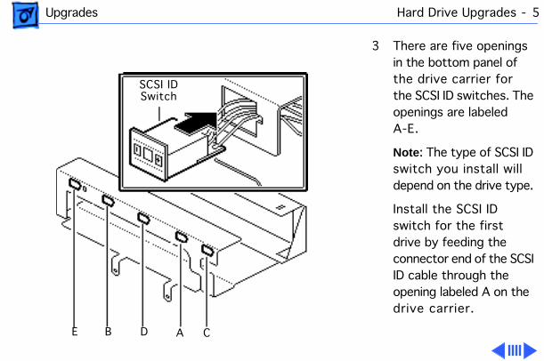
3 There are five openings in the bottom panel of the drive carrier for the SCSI ID switches. The openings are labeled A-E.
Note
: The type of SCSI ID switch you install will depend on the drive type.
Install the SCSI ID switch for the first drive by feeding the connector end of the SCSI ID cable through the opening labeled A on the drive carrier.
SCSI IDSwitch
E B D A C
Upgrades Hard Drive Upgrades - 6
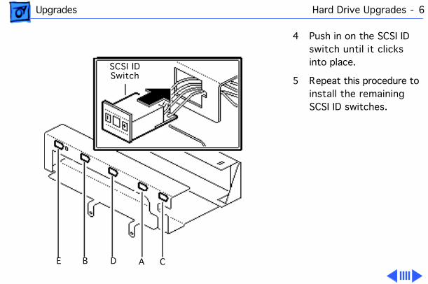
4 Push in on the SCSI ID switch until it clicks into place.
5 Repeat this procedure to install the remaining SCSI ID switches.
SCSI IDSwitch
E B D A C
Upgrades Hard Drive Upgrades - 7
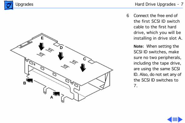
6 Connect the free end of the first SCSI ID switch cable to the first hard drive, which you will be installing in drive slot A.
Note:
When setting the SCSI ID switches, make sure no two peripherals, including the tape drive, are using the same SCSI ID. Also, do not set any of the SCSI ID switches to 7.
A
B
E
D
C
Upgrades Hard Drive Upgrades - 8
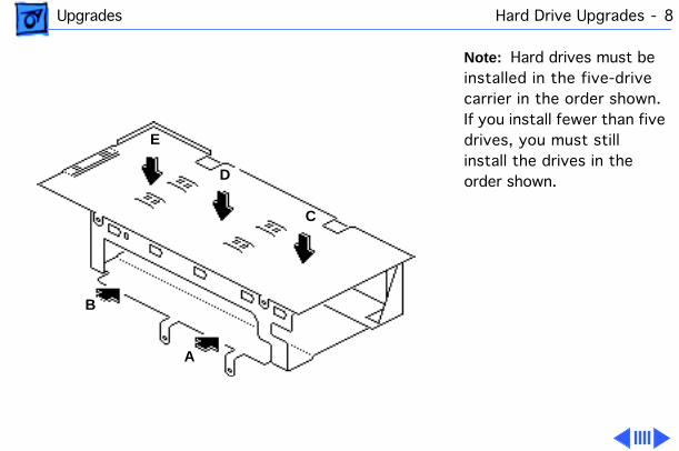
Note:
Hard drives must be installed in the five-drive carrier in the order shown. If you install fewer than five drives, you must still install the drives in the order shown.
A
B
E
D
C
Upgrades Hard Drive Upgrades - 9
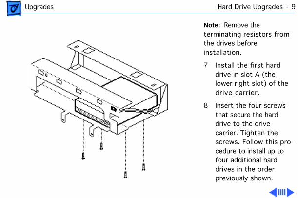
Note:
Remove the terminating resistors from the drives before installation.
7 Install the first hard drive in slot A (the lower right slot) of the drive carrier.
8 Insert the four screws that secure the hard drive to the drive carrier. Tighten the screws. Follow this pro-cedure to install up to four additional hard drives in the order previously shown.
Upgrades Hard Drive Upgrades - 10
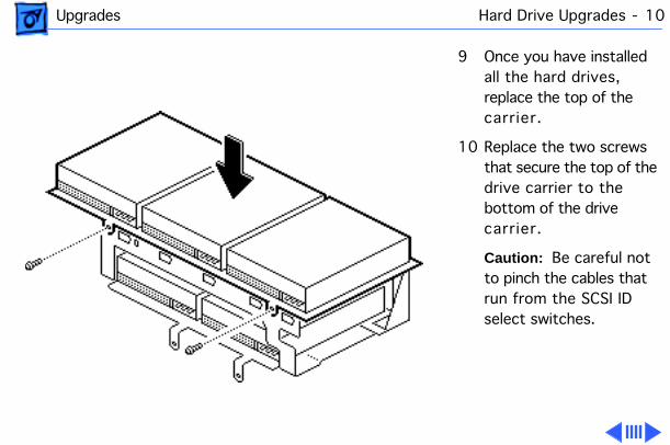
9 Once you have installed all the hard drives, replace the top of the carrier.
10 Replace the two screws that secure the top of the drive carrier to the bottom of the drive carrier.
Caution:
Be careful not to pinch the cables that run from the SCSI ID select switches.
Upgrades Hard Drive Upgrades - 11
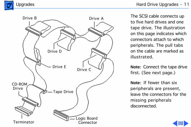
The SCSI cable connects up to five hard drives and one tape drive. The illustration on this page indicates which connectors attach to which peripherals. The pull tabs on the cable are marked as illustrated.
Note:
Connect the tape drive first. (See next page.)
Note:
If fewer than six peripherals are present, leave the connectors for the missing peripherals disconnected.
Ê
CD-ROM Drive
Terminator
Drive B
Drive D
Drive E
Tape Drive
Logic Board Connector
Drive C
Drive A
Upgrades Hard Drive Upgrades - 12
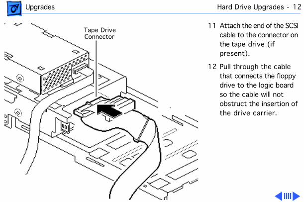
11 Attach the end of the SCSI cable to the connector on the tape drive (if present).
12 Pull through the cable that connects the floppy drive to the logic board so the cable will not obstruct the insertion of the drive carrier.
Tape Drive Connector
Upgrades Hard Drive Upgrades - 13
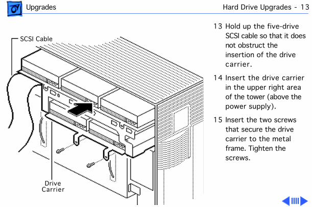
13 Hold up the five-drive SCSI cable so that it does not obstruct the insertion of the drive carrier.
14 Insert the drive carrier in the upper right area of the tower (above the power supply).
15 Insert the two screws that secure the drive carrier to the metal frame. Tighten the screws.
SCSI Cable
Drive Carrier
Upgrades Hard Drive Upgrades - 14
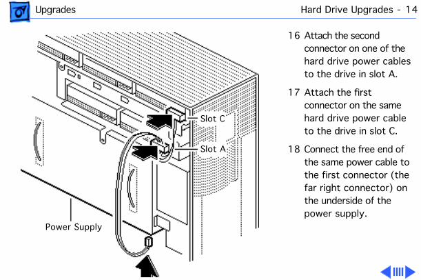
16 Attach the second connector on one of the hard drive power cables to the drive in slot A.
17 Attach the first connector on the same hard drive power cable to the drive in slot C.
18 Connect the free end of the same power cable to the first connector (the far right connector) on the underside of the power supply.
Slot C
Slot A
Power Supply
Upgrades Hard Drive Upgrades - 15
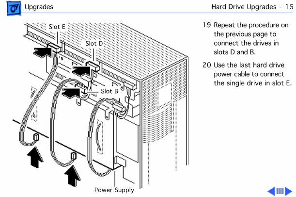
19 Repeat the procedure on the previous page to connect the drives in slots D and B.
20 Use the last hard drive power cable to connect the single drive in slot E.
Slot E
Slot D
Power Supply
Slot B
Upgrades Hard Drive Upgrades - 16
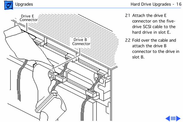
21 Attach the drive E connector on the five-drive SCSI cable to the hard drive in slot E.
22 Fold over the cable and attach the drive B connector to the drive in slot B.
Drive EConnector
Drive BConnector
Upgrades Hard Drive Upgrades - 17
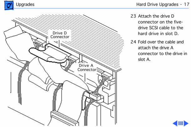
23 Attach the drive D connector on the five-drive SCSI cable to the hard drive in slot D.
24 Fold over the cable and attach the drive A connector to the drive in slot A.
Drive DConnector
Drive AConnector
Upgrades Hard Drive Upgrades - 18
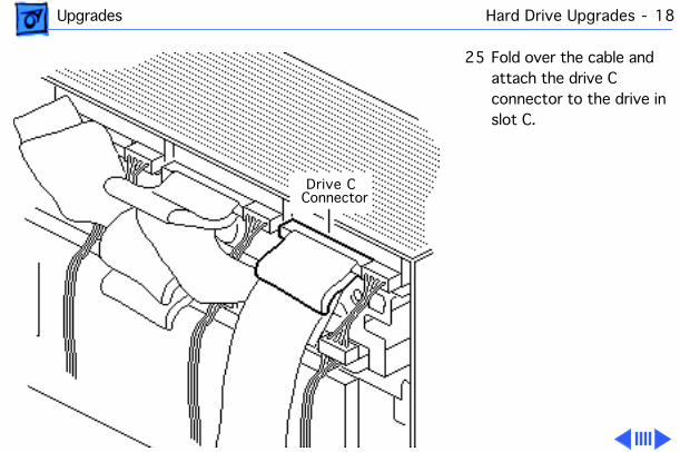
25 Fold over the cable and attach the drive C connector to the drive in slot C.
Drive CConnector
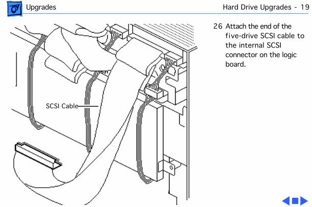
Upgrades Hard Drive Upgrades - 19
26 Attach the end of the five-drive SCSI cable to the internal SCSI connector on the logic board.
SCSI Cable
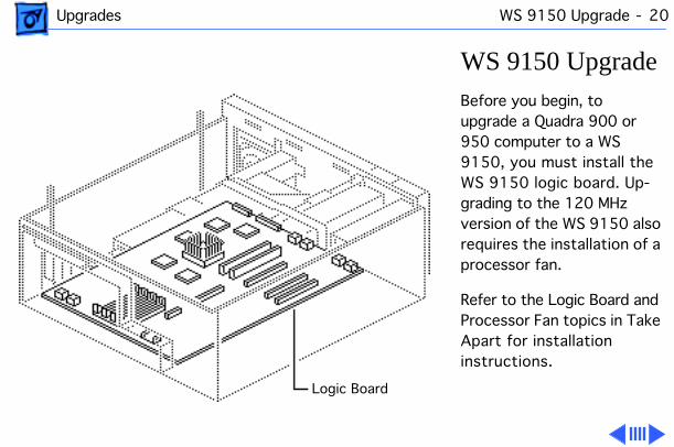
Upgrades WS 9150 Upgrade - 20
WS 9150 Upgrade
Before you begin, to upgrade a Quadra 900 or 950 computer to a WS 9150, you must install the WS 9150 logic board. Up-grading to the 120 MHz version of the WS 9150 also requires the installation of a processor fan.
Refer to the Logic Board and Processor Fan topics in Take Apart for installation instructions.
Logic Board
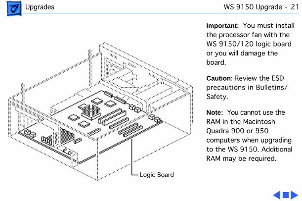
Upgrades WS 9150 Upgrade - 21
Important:
You must install the processor fan with the WS 9150/120 logic board or you will damage the board.
Caution
: Review the ESD precautions in Bulletins/Safety.
Note:
You cannot use the RAM in the Macintosh Quadra 900 or 950 computers when upgrading to the WS 9150. Additional RAM may be required.
Logic Board
Service Source
K
Additional Procedures
Workgroup Server 9150
Additional Procedures Battery Verification - 1
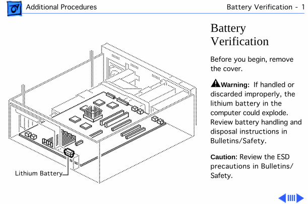
Battery Verification
Before you begin, remove the cover.
±
Warning:
If handled or discarded improperly, the lithium battery in the computer could explode. Review battery handling and disposal instructions in Bulletins/Safety.
Caution
: Review the ESD precautions in Bulletins/Safety.Lithium Battery
Additional Procedures Battery Verification - 2
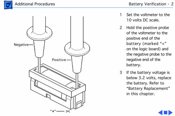
1 Set the voltmeter to the 10 volts DC scale.
2 Hold the positive probe of the voltmeter to the positive end of the battery (marked “+” on the logic board) and the negative probe to the negative end of the battery.
3 If the battery voltage is below 3.2 volts, replace the battery. Refer to “Battery Replacement” in this chapter.
Negative
Positive

Additional Procedures Battery Replacement - 3
Battery Replacement
Before you begin, remove the cover.
±
Warning:
If handled or discarded improperly, the lithium battery in the computer could explode. Review battery handling and disposal instructions in Bulletins/Safety.
Caution
: Review the ESD precautions in Bulletins/Safety. Lithium Battery
Additional Procedures Battery Replacement - 4
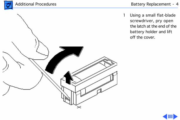
1 Using a small flat-blade screwdriver, pry open the latch at the end of the battery holder and lift off the cover.
Additional Procedures Battery Replacement - 5
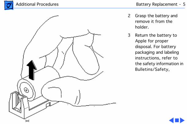
2 Grasp the battery and remove it from the holder.
3 Return the battery to Apple for proper disposal. For battery packaging and labeling instructions, refer to the safety information in Bulletins/Safety,
Additional Procedures Reset Logic Board - 6
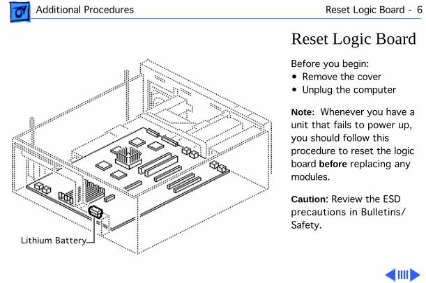
Reset Logic Board
Before you begin:• Remove the cover• Unplug the computer
Note:
Whenever you have a unit that fails to power up, you should follow this procedure to reset the logic board
before
replacing any modules.
Caution
: Review the ESD precautions in Bulletins/Safety.
Lithium Battery
Additional Procedures Reset Logic Board - 7
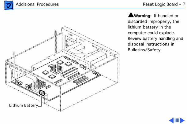
±
Warning:
If handled or discarded improperly, the lithium battery in the computer could explode. Review battery handling and disposal instructions in Bulletins/Safety.
Lithium Battery
Additional Procedures Reset Logic Board - 8
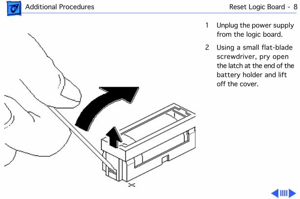
1 Unplug the power supply from the logic board.
2 Using a small flat-blade screwdriver, pry open the latch at the end of the battery holder and lift off the cover.
Additional Procedures Reset Logic Board - 9
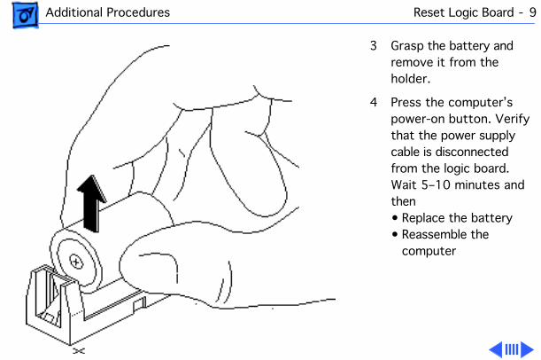
3 Grasp the battery and remove it from the holder.
4 Press the computer’s power-on button. Verify that the power supply cable is disconnected from the logic board. Wait 5–10 minutes and then• Replace the battery• Reassemble the
computer
Additional Procedures Reset Logic Board - 10
Note:
This procedure resets PRAM. Be sure to check the computer’s time/date and other system parameter settings.
Note:
If this procedure resolves the problem, claim an adjustment on an SRO. If not, replace defective component and
do not
claim the adjustment procedure.
Service Source
K
Exploded View
Workgroup Server 9150
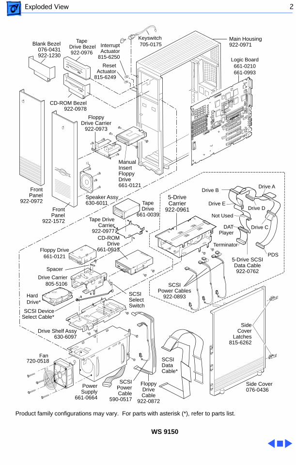
Exploded View 2
Logic Board661-0210661-0993
Speaker Assy630-6011
Main Housing922-0971
Keyswitch705-0175Interrupt
Actuator815-6250
Tape Drive Bezel
922-0976
CD-ROM Bezel922-0978
Blank Bezel076-0431922-1230
FrontPanel
922-0972
FrontPanel
922-1572
ResetActuator
815-6249
FloppyDrive Carrier
922-0973
Manual InsertFloppy Drive661-0121
Drive Shelf Assy 630-6097
SCSIData Cable*
5-Drive SCSI Data Cable922-0762
Side Cover076-0436
SideCover
Latches815-6262
Floppy Drive661-0121
Drive Carrier805-5106
SCSIPowerCable
590-0517
SCSIPower Cables
922-0893
FloppyDrive Cable
922-0872
HardDrive*
Drive C
Drive A
Drive D
Drive B
Drive E
DATPlayer
Terminator
PDS
PowerSupply
661-0664
Fan
Spacer
SCSI SelectSwitch
SCSI DeviceSelect Cable*
Tape Drive
661-0039Tape Drive
Carrier922-0977
CD-ROMDrive
661-0913
Not Used
5-DriveCarrier
922-0961
WS 9150
720-0518
Product family configurations may vary. For parts with asterisk (*), refer to parts list.