Embed Size (px)
Citation preview
UNIVERSAL LIBRARY
USERS GUIDE
ComputerBoards, Inc.Revision 5.2May, 2000
MEGA-FIFO, the CIO prefix to data acquisition board model numbers, the PCM prefix to data acquisition board model numbers,PCM-DAS08, PCM-D24C3, PCM-DAC02, PCM-COM422, PCM-COM485, PCM-DMM, PCM-DAS16D/12,PCM-DAS16S/12, PCM-DAS16D/16, PCM-DAS16S/16, PCI-DAS6402/16, Universal Library, InstaCal, Harsh EnvironmentWarranty and ComputerBoards are registered trademarks of ComputerBoards, Inc.
IBM, PC, and PC/AT are trademarks of International Business Machines Corp. Windows is a trademark of Microsoft Corp. Allother trademarks are the property of their respective owners.
Information furnished by ComputerBoards, Inc. is believed to be accurate and reliable. However, no responsibility is assumed byComputerBoards, Inc. neither for its use; nor for any infringements of patents or other rights of third parties, which may resultfrom its use. No license is granted by implication or otherwise under any patent or copyrights of ComputerBoards, Inc.
All rights reserved. No part of this publication may be reproduced, stored in a retrieval system, or transmitted, in any form by anymeans, electronic, mechanical, by photocopying, recording or otherwise without the prior written permission ofComputerBoards, Inc.
NoticeComputerBoards, Inc. does not authorize any ComputerBoards, Inc. product for use in life supportsystems and/or devices without the written approval of the President of ComputerBoards, Inc. Lifesupport devices/systems are devices or systems which, a) are intended for surgical implantationinto the body, or b) support or sustain life and whose failure to perform can be reasonablyexpected to result in injury. ComputerBoards, Inc. products are not designed with the componentsrequired, and are not subject to the testing required to ensure a level of reliability suitable for thetreatment and diagnosis of people.
SM UL User guide.lwp

TABLE OF CONTENTS
14If using VEE 3.2 or Later . . . . . . . . . . . . . . . . . . . . . . . . . . . . . . . . . . . .14Must Install Universal Library in Default Directory. . . . . . . . . . . . . . . . . .14New HP VEE Functions. . . . . . . . . . . . . . . . . . . . . . . . . . . . . . . . . . . . .134.7 USING THE LIBRARY WITH HP VEE . . . . . . . . . . . . . . . . . . . . . . . . . . . . . . . . . .124.6 USING THE LIBRARY WITH C FOR DOS. . . . . . . . . . . . . . . . . . . . . . . . . . . . . . . .12Compiling Stand Alone EXE files. . . . . . . . . . . . . . . . . . . . . . . . . . . . . .124.5 USING THE LIBRARY WITH VISUAL BASIC FOR DOS . . . . . . . . . . . . . . . . . . . . .11BACKGROUND operation . . . . . . . . . . . . . . . . . . . . . . . . . . . . . . . . . . .11Integer Arguments . . . . . . . . . . . . . . . . . . . . . . . . . . . . . . . . . . . . . . . . .11Using String Arguments . . . . . . . . . . . . . . . . . . . . . . . . . . . . . . . . . . . . .11DataArray Argument with Multiple Channels. . . . . . . . . . . . . . . . . . . . . .10Passing Arguments to Universal Library. . . . . . . . . . . . . . . . . . . . . . . . . .10Sample Basic Programs. . . . . . . . . . . . . . . . . . . . . . . . . . . . . . . . . . . . . .9Using The Library With The BASIC Command Line Compiler. . . . . . . . . .9Using The Library Within The Integrated BASIC Environment. . . . . . . . . .9BASIC Header File. . . . . . . . . . . . . . . . . . . . . . . . . . . . . . . . . . . . . . . . . .94.4 USING THE LIBRARY WITH DOS BASIC . . . . . . . . . . . . . . . . . . . . . . . . . . . . . . . .8Delphi Example Programs. . . . . . . . . . . . . . . . . . . . . . . . . . . . . . . . . . . . .8Borland C/C++ Example Programs. . . . . . . . . . . . . . . . . . . . . . . . . . . . . .8Borland C/C++ For Windows . . . . . . . . . . . . . . . . . . . . . . . . . . . . . . . . . .8Microsoft Visual C++ Example Programs. . . . . . . . . . . . . . . . . . . . . . . . . .8Microsoft Visual C++ . . . . . . . . . . . . . . . . . . . . . . . . . . . . . . . . . . . . . . . .7Visual Basic Example Programs. . . . . . . . . . . . . . . . . . . . . . . . . . . . . . . .7CB.CFG Locations with Visual Basic. . . . . . . . . . . . . . . . . . . . . . . . . . . .7Visual Basic for Windows. . . . . . . . . . . . . . . . . . . . . . . . . . . . . . . . . . . . .7Processor Speed. . . . . . . . . . . . . . . . . . . . . . . . . . . . . . . . . . . . . . . . . . . .7Real Time Operation Under Windows. . . . . . . . . . . . . . . . . . . . . . . . . . . .64.3 USING UNIVERSAL LIBRARY IN WINDOWS . . . . . . . . . . . . . . . . . . . . . . . . . . . . .6Error Handling . . . . . . . . . . . . . . . . . . . . . . . . . . . . . . . . . . . . . . . . . . . . .5Options Arguments. . . . . . . . . . . . . . . . . . . . . . . . . . . . . . . . . . . . . . . . . .5Constants. . . . . . . . . . . . . . . . . . . . . . . . . . . . . . . . . . . . . . . . . . . . . . . . .5Function Arguments. . . . . . . . . . . . . . . . . . . . . . . . . . . . . . . . . . . . . . . . .54.2 GENERAL UL LANGUAGE INTERFACE DESCRIPTION . . . . . . . . . . . . . . . . . . . . . .54.1 HOW TO USE THE LIBRARY SUCCESSFULLY . . . . . . . . . . . . . . . . . . . . . . . . . . . .54.0 HOW TO USE THE LIBRARY . . . . . . . . . . . . . . . . . . . . . . . . . . . . . . . . . . . . . . . .43.3 The CB.CFG FILE & InstaCAL . . . . . . . . . . . . . . . . . . . . . . . . . . . . . . . . . . . . . . . . .33.2 INSTALLATION - HP VEE SUPPORT. . . . . . . . . . . . . . . . . . . . . . . . . . . . . . . . . . . .33.1 INSTALLATION OVERVIEW . . . . . . . . . . . . . . . . . . . . . . . . . . . . . . . . . . . . . . . . .33.0 INSTALLATION AND CONFIGURATION . . . . . . . . . . . . . . . . . . . . . . . . . . . . . . .22.0 UNIVERSAL LIBRARY DESCRIPTION . . . . . . . . . . . . . . . . . . . . . . . . . . . . . . . .11.0 INTRODUCTION . . . . . . . . . . . . . . . . . . . . . . . . . . . . . . . . . . . . . . . . . . . . . . . . . .

4811.3 PPIO-CTR06 BOARDS . . . . . . . . . . . . . . . . . . . . . . . . . . . . . . . . . . . . . . . . . . . .4711.2 CIO-, AND PCI- INT32 . . . . . . . . . . . . . . . . . . . . . . . . . . . . . . . . . . . . . . . . . . . .4611.1 CIO-, PCI-, PC104- AND cSBX CTR SERIES. . . . . . . . . . . . . . . . . . . . . . . . . . . . . .4611.0 COUNTER BOARDS . . . . . . . . . . . . . . . . . . . . . . . . . . . . . . . . . . . . . . . . . . . . . .4410.2 CIO- AND PC104-, DO## AND DO##DD SERIES. . . . . . . . . . . . . . . . . . . . . . . . . .4410.1 CIO-RELAY SERIES . . . . . . . . . . . . . . . . . . . . . . . . . . . . . . . . . . . . . . . . . . . . . .4410.0 DIGITAL OUTPUT . . . . . . . . . . . . . . . . . . . . . . . . . . . . . . . . . . . . . . . . . . . . . . .439.2 CIO-DISO48 BOARDS . . . . . . . . . . . . . . . . . . . . . . . . . . . . . . . . . . . . . . . . . . . . .439.1 CIO- AND PC104- DIxx SERIES BOARDS. . . . . . . . . . . . . . . . . . . . . . . . . . . . . . . .439.0 DIGITAL INPUT . . . . . . . . . . . . . . . . . . . . . . . . . . . . . . . . . . . . . . . . . . . . . . . . . .428.5 CIO-PDMA16 AND CIO-PDMA32 . . . . . . . . . . . . . . . . . . . . . . . . . . . . . . . . . . . . .418.4 CIO-, PC104-, AND PCI- PDISO8 AND PDISO16. . . . . . . . . . . . . . . . . . . . . . . . . . .418.3 PCI-DIO48H/CTR15 . . . . . . . . . . . . . . . . . . . . . . . . . . . . . . . . . . . . . . . . . . . . . . .418.2 CIO- AND PCM- DIO24/CTR3, PC-CARD-D24/CTR3. . . . . . . . . . . . . . . . . . . . . . . .408.1 CIO-, PCI-, PC-CARD-, PC104- & PPIO- DIO SERIES BOARDS, CIO- & PCI-DUAL-AC5.408.0 DIGITAL INPUT / OUTPUT . . . . . . . . . . . . . . . . . . . . . . . . . . . . . . . . . . . . . . . . .397.13 CIO- & PCI-DAS-TC, CIO-DAS-TEMP. . . . . . . . . . . . . . . . . . . . . . . . . . . . . . . . . .377.12 PCM-DAS16x/xx & PC-CARD-DAS16/xx SERIES BOARDS. . . . . . . . . . . . . . . . . . .367.11 PCM-DAS08 BOARD . . . . . . . . . . . . . . . . . . . . . . . . . . . . . . . . . . . . . . . . . . . . .357.10 PPIO-AI8 . . . . . . . . . . . . . . . . . . . . . . . . . . . . . . . . . . . . . . . . . . . . . . . . . . . . . .347.9 CIO-DAS1400 & CIO-DAS1600 SERIES BOARDS. . . . . . . . . . . . . . . . . . . . . . . . . .337.8 CIO-DAS48/PGA BOARD . . . . . . . . . . . . . . . . . . . . . . . . . . . . . . . . . . . . . . . . . . .327.7 CIO- AND PC104- DAS16 SERIES BOARDS. . . . . . . . . . . . . . . . . . . . . . . . . . . . . .317.6 CIO-DAS800 SERIES BOARDS. . . . . . . . . . . . . . . . . . . . . . . . . . . . . . . . . . . . . . .307.5 CIO-DAS08/Jr & CIO-DAS08/Jr/16 BOARDS. . . . . . . . . . . . . . . . . . . . . . . . . . . . . .297.4 CIO-, PCI- AND PC104- DAS08 SERIES BOARDS. . . . . . . . . . . . . . . . . . . . . . . . . .277.3 PCI-, CIO-DAS6402/## SERIES. . . . . . . . . . . . . . . . . . . . . . . . . . . . . . . . . . . . . . .257.2 PCI-DAS1602, PCI-DAS1200 & PCI-DAS1000 series. . . . . . . . . . . . . . . . . . . . . . . . .227.1 PCI-DAS4020 series . . . . . . . . . . . . . . . . . . . . . . . . . . . . . . . . . . . . . . . . . . . . . . .227.0 ANALOG INPUT BOARDS . . . . . . . . . . . . . . . . . . . . . . . . . . . . . . . . . . . . . . . . . .216.6 PCI-DDA0x/xx SERIES BOARDS. . . . . . . . . . . . . . . . . . . . . . . . . . . . . . . . . . . . . .216.5 PCM-DAC02 & DAC08 BOARDS . . . . . . . . . . . . . . . . . . . . . . . . . . . . . . . . . . . . . .206.4 cSBX-DDA04 BOARD . . . . . . . . . . . . . . . . . . . . . . . . . . . . . . . . . . . . . . . . . . . . .206.3 CIO-DDA06 & DDA06/Jr SERIES. . . . . . . . . . . . . . . . . . . . . . . . . . . . . . . . . . . . . .196.2 CIO- AND PC104- DAC SERIES (EXCLUDING HS SERIES). . . . . . . . . . . . . . . . . . .196.1 CIO-DAC04/#-HS SERIES BOARDS. . . . . . . . . . . . . . . . . . . . . . . . . . . . . . . . . . . .196.0 ANALOG OUTPUT BOARDS . . . . . . . . . . . . . . . . . . . . . . . . . . . . . . . . . . . . . . . .185.8 USING THE RAM DISK . . . . . . . . . . . . . . . . . . . . . . . . . . . . . . . . . . . . . . . . . . . .175.7 INSTALLING A RAM DISK . . . . . . . . . . . . . . . . . . . . . . . . . . . . . . . . . . . . . . . . . .175.6 WHAT IS A RAM DISK? . . . . . . . . . . . . . . . . . . . . . . . . . . . . . . . . . . . . . . . . . . . .165.5 SPEEDING UP DISK FILES (DE-FRAGMENTING). . . . . . . . . . . . . . . . . . . . . . . . . .165.4 HOW TO DETERMINE MAXIMUM SAMPLING SPEED . . . . . . . . . . . . . . . . . . . . . .165.3 MAXIMUM SAMPLING SPEED . . . . . . . . . . . . . . . . . . . . . . . . . . . . . . . . . . . . . . .155.2 HARD DISK VS. RAM DISK FILES . . . . . . . . . . . . . . . . . . . . . . . . . . . . . . . . . . . .155.1 OVERVIEW . . . . . . . . . . . . . . . . . . . . . . . . . . . . . . . . . . . . . . . . . . . . . . . . . . . .155.0 USING THE FILE FUNCTIONS . . . . . . . . . . . . . . . . . . . . . . . . . . . . . . . . . . . . . .
5415.0 APPENDIX A. ERROR CODES . . . . . . . . . . . . . . . . . . . . . . . . . . . . . . . . . . . . . .5214.3 DEMO-BOARD . . . . . . . . . . . . . . . . . . . . . . . . . . . . . . . . . . . . . . . . . . . . . . . . .5214.2 CIO- AND PCM- COM 485. . . . . . . . . . . . . . . . . . . . . . . . . . . . . . . . . . . . . . . . . .5214.1 CIO- AND PCM- COM 422. . . . . . . . . . . . . . . . . . . . . . . . . . . . . . . . . . . . . . . . . .5214.0 OTHER FUNCTIONS . . . . . . . . . . . . . . . . . . . . . . . . . . . . . . . . . . . . . . . . . . . . .5113.6 MSSR-24 . . . . . . . . . . . . . . . . . . . . . . . . . . . . . . . . . . . . . . . . . . . . . . . . . . . . . .5113.5 MEM-32 . . . . . . . . . . . . . . . . . . . . . . . . . . . . . . . . . . . . . . . . . . . . . . . . . . . . . .5113.4 MEM-8 . . . . . . . . . . . . . . . . . . . . . . . . . . . . . . . . . . . . . . . . . . . . . . . . . . . . . . .5113.3 MII-32 . . . . . . . . . . . . . . . . . . . . . . . . . . . . . . . . . . . . . . . . . . . . . . . . . . . . . . . .5013.2 MIO-32 . . . . . . . . . . . . . . . . . . . . . . . . . . . . . . . . . . . . . . . . . . . . . . . . . . . . . . .5013.1 ISA-, PCI- and PC104-MDB64 SERIES BOARDS. . . . . . . . . . . . . . . . . . . . . . . . . . .5013.0 METRABUS BOARDS . . . . . . . . . . . . . . . . . . . . . . . . . . . . . . . . . . . . . . . . . . . . .5012.2 MEGA-FIFO BOARD . . . . . . . . . . . . . . . . . . . . . . . . . . . . . . . . . . . . . . . . . . . . .4912.1 CIO-EXP SERIES BOARDS. . . . . . . . . . . . . . . . . . . . . . . . . . . . . . . . . . . . . . . . .4912.0 EXPANSION BOARDS . . . . . . . . . . . . . . . . . . . . . . . . . . . . . . . . . . . . . . . . . . . .4811.4 CIO- PCI- AND PCM- QUAD SERIES. . . . . . . . . . . . . . . . . . . . . . . . . . . . . . . . . .

This page is blank intentionally.

1.0 INTRODUCTION
Congratulations and thank you for your selection of Universal Library. We believe it is the mostcomprehensive, easiest to use data acquisition software interface available anywhere. As easy as UniversalLibrary is to use, significant documentation and explanation is still required to help new users get going,and allow existing users to take advantage of all the package's powerful features.
The fast changing nature of the software industry makes it very difficult to provide a totally up to date userguide in written form. Adding to this complexity are the new features and functions that are constantly beingadded to the library. To provide the most complete information possible, and at the same time keep theinformation current, we offer the Universal Library user guide and documentation in four parts. These are:
1. The Universal Library User's Guide (this document). The user's guide provides a generaldescription of the UL and offers an overview of the various features and functions and how theymay be used in different operating systems and languages. The user's guide also provides a sectionthat describes the various functions and features as they pertain to specific ComputerBoardsproducts.
2. The Universal Library Function Reference. The Function Reference provides completedetails on the features, usage and options of the many Universal Library functions.
3. Example Programs. Perhaps the most valuable, and easiest of all the tools to use. We provideexample programs in all the popular languages that include many of the popular functions. Allof the example programs are fully functional and provided an ideal starting place for your ownprogramming effort. It's easier to cut-and-paste pieces from a known, working program thanit is to start writing everything from scratch.
4. Read Me Files. The only way to get the absolute, latest, most up to date information to ourusers is through Read Me files. We incorporate this information into our main streamdocumentation as quickly as we can, but for the latest, greatest information, please take the timeto read the various read me files.
1
2.0 UNIVERSAL LIBRARY DESCRIPTION
The Computer Boards Universal Library is the software that you need to write your own programs that useany of the Computer Boards data acquisition and control boards.
The library is universal in three ways.
Universal Across Boards - The library contains high level functions for all of the common operations forall boards. Each of the boards has different hardware but the Universal Library hides these differences fromyour program. So, for example, a program written for use with one A/D board will work "as is" with adifferent A/D board.
Universal Across Languages - The Universal Library provides the identical set of functions and argumentsfor BASIC, C, and Pascal. If you switch languages you won't have to learn a new library, with new syntax,and different features.
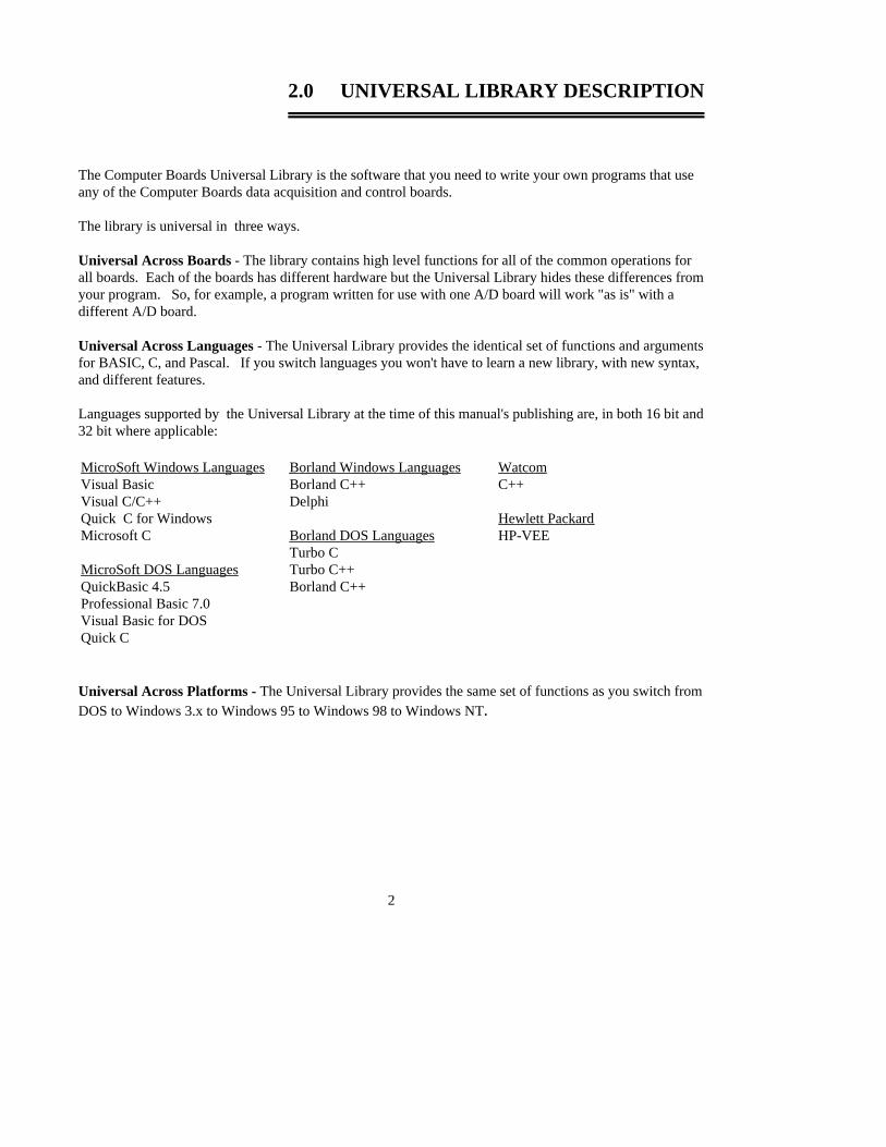
Languages supported by the Universal Library at the time of this manual's publishing are, in both 16 bit and32 bit where applicable:
WatcomC++
Hewlett PackardHP-VEE
Borland Windows LanguagesBorland C++Delphi
Borland DOS LanguagesTurbo CTurbo C++Borland C++
MicroSoft Windows LanguagesVisual BasicVisual C/C++Quick C for WindowsMicrosoft C
MicroSoft DOS LanguagesQuickBasic 4.5Professional Basic 7.0Visual Basic for DOSQuick C
Universal Across Platforms - The Universal Library provides the same set of functions as you switch fromDOS to Windows 3.x to Windows 95 to Windows 98 to Windows NT.
2

3.0 INSTALLATION AND CONFIGURATION
InstaCAL is ComputerBoards’ powerful installation, test and calibration software package and is shipped free with every board. It is also installed as part of the Universal Library package installation.
In addition to the information provided here, please also refer to the Software Installation Manual providedwith your disks or CD, and check the read me files on the disk/CD you receive. Due to the rapidly changingnature of the software world, it is very difficult to keep a totally up to date manual in written form.
3.1 INSTALLATION OVERVIEW
Please use the Software Installation Manual as a guide for installing the Universal Library and Instacal.Where possible, use the default for all options presented as it will be easier to assist you in the event of aproblem if the default options are selected.
Windows 95 and 98 users are given the option to install the 32-bit library, the 16-bit library or both. Unlessyou have a specific reason to choose otherwise, we recommend you install only the 32-bit library (thedefault setting).
3.2 INSTALLATION - HP VEE SUPPORT
Please use the Software Installation Manual as a guide for installing the Universal Library and Instacal.Where possible, use the default for all options presented as it will be easier to assist you in the event of aproblem if the default options are selected.
The modifications made to your system when installing HP VEE Support is identical to the modificationsmade when installing the Universal Library with the following exceptions:
y In the directory where VEE resides, the menu bar program VEE.MNU is written (or CBI.MNN,depending on version).
NOTE: If you are using a custom VEE.MNU, such as the one shipped with DT-VEE, it may beoverwritten by the install program. Please call ComputerBoards technical support for information onhandling multiple custom menu bars.
y In the directory where the VEE programs (examples and your programs) reside, examples are added.The Universal Library examples for VEE use ComputerBoards’ standard names for examples (see thechart in the section on examples) with the .VEE extension.
3

Although you are finished installing HP VEE and the drivers to link VEE to ComputerBoards I/O boards,there is one more step to complete before you can use VEE with an I/O board. You must run the programInstaCal.Exe and configure the driver. The program InstaCal is an installation, calibration and test programwhich creates a required configuration file describing the specifics of the hardware installed.
3.3 The CB.CFG FILE & InstaCAL
All board specific information, including current installed options, are stored in the file CB.CFG which isread by UniversalLibrary. InstaCal creates and/or modifies this file when board configuration informationis added or updated. The Universal Library will not function without the CB.CFG file. For this reason it iscrucial that you use InstaCAL to modify all board setups and configurations as well as to install or removeboards from your system.
OVERVIEW OF THE UNIVERSAL LIBRARY The Universal Library consists of a set of functions that are callable from your program. These functionsare grouped according to their purpose. All of the groups except for Misc. are based on which type ofdevices they are used with.
VERY IMPORTANT NOTEIn order to understand the functions, you should read the Board Specific Informationsection found elsewhere in this manual and in the readme files supplied on the UniversalLibrary Disk. We also urge you to examine and run one or more of the exampleprograms supplied prior to attempting any programming of your own. Following thisadvice may save you hours of frustration, and wasted time.
4

4.0 HOW TO USE THE LIBRARY
The Computer Boards Universal Library is callable from Quick BASIC, Professional BASIC, VisualBASIC, Visual C++, Microsoft C, Quick C, Turbo C, and Borland C++. This chapter describes how to usethe library from each of the languages. The first section of the chapter describes details of the library thatapply to all languages. The following sections describe the differences for each language.
4.1 HOW TO USE THE LIBRARY SUCCESSFULLY
1. Set up and test your boards with InstaCal. The library will not function until InstaCal has created aconfiguration file.
2. Use the example programs for the language you program in. This manual explains the functionsand contains other necessary information, but it is incomplete without reference to and review ofthe examples.
4.2 GENERAL UL LANGUAGE INTERFACE DESCRIPTION
The interface to all languages is a set of function calls and a set of constants. The list of function calls andconstants are identical for each language. All of the functions and constants are defined in a "header" filefor each language. Refer to the sections below and especially to the example programs for each language. This manual is brief with respect to details of language use and syntax. The examples must be examined forthis information.
Function ArgumentsEach library function takes a list of arguments and returns an error code. Some functions also return datavia their arguments. For example one of the arguments to cbAIn() is the name of a variable in which theanalog input value will be stored. All function arguments that return data are listed in the "Returns:".
ConstantsMany functions take arguments that must be set to one of a small number of choices. These choices are allgiven symbolic constant names. So for example, TIn() takes an argument called Scale that must be set toCELSIUS, FAHRENHEIT, or KELVIN. These constant names are defined and assigned a value in the"header" file for each language. Although it is possible to use the numbers rather than the symbolicconstant names, we strongly recommend that you use the names. This will make your programs morereadable and more compatible with future versions of the library. The numbers may change in futureversions but the symbolic names will always remain the same.
Options ArgumentsSome library functions have an argument called Options and all options have a default. Some options havean alternative, such as, DTCONNECT and NODTCONNECT, one of which is the default value. Otheroptions do not have a stated alternative. The alternative is the absence of that option. The option argument
5

is used to turn on and off various optional features associated with the function. If you set Options=0 thenthe function will set all of these options to the default value, or off.
Individual options can be turned on by adding them to the Options argument. So, for example, Options =BACKGROUND will turn on the "background execution" feature. Options =BACKGROUND+CONTINUOUS will select both the "background execution" and the "continuousexecution" feature.
Error HandlingAll library functions return an error code. If no error occurred during that library call then the error codewill be set to 0, otherwise it will be set to one of the codes listed in Appendix A.
If a non-zero error code is returned then cbGetErrMsg() can be used to convert the error code to a specificerror message. As an alternative to checking the error code after each function call you may choose to turnon the library's internal error handling with cbErrHandling().
4.3 USING UNIVERSAL LIBRARY IN WINDOWS
A Windows DLL version of the Universal Library (CBW.DLL) may be called from any language thatsupports calls to external 16-bit DLLs. Example programs for Visual Basic and both Borland and MS Cillustrate the use of CBW.DLL. A 32-bit Windows version of the Universal Library (CBW32.DLL) may becalled from any language that supports calls to external 32-bit DLLs.
Due to the differences in memory management among various operating systems, the scan commands haveslightly different argument lists. In DOS libraries all scan commands take a pointer to a data array as oneof their arguments. In the Windows 3.x these functions take a handle to a Windows Global Memory bufferinstead of a pointer to an array. In the 32-bit Windows version, these functions take a pointer (a 32-bitvirtual address) or a handle returned from cbWinBufAlloc(). The affected functions are:
cbAInScan()cbAOutScan()cbAPretrig()cbDInScan()cbDOutScan()
The Windows library also contains four functions for managing these Windows global memory buffers.The functions are:
cbWinBufAlloc()cbWinBufFree()cbWinArrayToBuf()cbWinBufToArray()
6
Real Time Operation Under WindowsReal time operation is available from Windows. To operate at full speed under Windows, the A/D boardmust have a FIFO buffer. All of ComputerBoards' advanced designs have FIFO buffers. These include theCIO-DAS80x, CIO-DAS160x, CIO-DAS140x, CIO-DAS16/330x and PCM-DAS16x. All these dataacquisition boards will operate at full speed in real time under Windows. See the note on real time softwarecalibration and the function cbACalibrateData().
Processor SpeedProcessor speed remains a factor for DMA transfers and for real time software calibration. Processors ofless than 150MHz Pentium class may impose speed limits below the capability of the board. See the boardspecific information and the notes on real time software calibration.
Visual Basic for WindowsYou must include the Universal Library declaration file CBW.BAS in your program. You may do so byincluding it in the form that calls the library or add it as a module in your project. Once the declarations forthe UL have been added to your project, you can call the CBW.DLL from any Form's event handlers.
When using 32-bit version of Visual Basic, CBW.BAS references CBW32.DLL to call Universal Libraryfunctions. This is accomplished with conditional compile statements. When using VB3 or older, thesestatements must be deleted.
In Visual BASIC there is no way to map a Windows global memory block onto a user array. Because ofthis the cbWinArrayToBuf() and cbWinBufToArray() functions must be used to copy data between arraysand Windows buffers (and vice versa).
Example: Count& = 100 MemHandle% = cbWinBufAlloc (Count&) cbAInScan (......,MemHandle%,...) cbWinBufToArray (MemHandle%, DataArray%(0), 0, Count&) FOR i = 0 to Count& PRINT DataArray%(i) NEXT cbWinBufFree (MemHandle%)
CB.CFG Locations with Visual BasicAll programs that use the Universal Library read the CB.CFG configuration file. Be sure to include a copyof the CB.CFG configuration file with any compiled stand alone Visual Basic programs you wish todistribute to another machine or directory.
Visual Basic Example ProgramsA complete set of Visual BASIC example programs is included. Each program illustrates the use of oneUniversal Library function from within a Visual BASIC program. The .FRM files contain the programs.The corresponding .MAK file is the Project file which is used to build the program for Visual Basic. TheDLL referenced in the declaration will be cbw.dll (16-bit) or cbw32.dll (32-bit). Conditional compilestatements ("#IF", "#ELSE", "#ENDIF") determine which DLL is used. If your version of VB does notsupport these statements, please refer to the instructions in CBW.BAS for removing them.
7
Microsoft Visual C++To use the Universal Library from Visual C++ for Windows, include the header file CBW.H in your Cprogram and add the library file CBW.LIB to your project.
When using 32-bit version of Visual C++, you must replace the library file CBW.LIB with CBW32.LIB.CBW32.LIB uses CBW32.DLL to call Universal Library functions.
Microsoft Visual C++ Example ProgramsThe Wincai## programs are examples of simple C programs that call the Universal Library. Theseprograms contain directives for building 16 OR 32 bit applications. You can use the .MAK project files tobuild a 16 bit application and the .DSP project files to build a 32 bit application.
Only a few of the Universal Library functions are included in these Window examples. The non-WindowsC examples provide a more complete set of examples. These can be compiled as 32-bit console applicationsfor Windows 95/98/NT by using the makemc32.bat file.
Borland C/C++ For WindowsThe ULAIOx programs are examples of simple C programs that call the Universal Library. You can use theexample project ULAIO1.IDE to build an example program. Simply replace ULAIO1.C with ULAIOx.C inyour project to build on of the other examples. The program expects an 8 channel A/D board. You canmodify the program for the board you own.
When using 16-bit Borland C/C++, use a tool called IMPLIB that came with your computer to generate anOMF-style import library that your application can link with.
In 32-bit systems users may take advantage of the cbw32bc.lib import library. For 16-bit users IMPLIBaccepts a DLL(CBW.DLL) as input and emits an OMF-style import library (BCBW.LIB). When using16-bit version of Borland C/C++, you can run IMPLIB on CBW16.DLL to emit a 16-bit OMF-style importlibrary(BCBW32.LIB).
Borland C/C++ Example ProgramsThe ULAI01 program is an example of a simple C++ program that calls the Universal Library. To build theprogram use ULAI01.PRJ. The program expects an 8 channel A/D board. You can modify the program forthe board you own.
When you build the ULAIOx program the compiler will generate two warning messages which can besafely ignored. They are,
Parameter 'CmdLine' is never used.Stack size is less than 1400h. It has been reset to 1400h.
the second of which may be corrected by adding the line STACK = 0x1400 to the WINCDEMO program.It is not included in the ULAIOx program because it generates an error in MS VC++.
The non-Windows C examples provide a more complete set of examples. These can be compiled as 32-bitconsole applications for Windows 95/98/NT by using the makebc32.bat file.
Delphi Example ProgramsA complete set of Delphi example programs is included. Each program illustrates the use of one UniversalLibrary function from within a Delphi program. The.PAS files contain the programs. The corresponding.DPR file is the Project file used to build the program in a 16 bit or 32 bit Delphi environment.
8
16 bit Delphi environments use the cbw.dll header. 32 bit Delphi environments use the cbw32.dll header.Conditionals within the example programs determine which of the DLLs is used.
Where integers are passed by reference to a Universal Library function, you should use the SmallInt datatype in 32 bit environments. The relevant functions are defined this way in the 32 bit header, so if you tryto pass an Integer data type you will get a compiler error.
4.4 USING THE LIBRARY WITH DOS BASIC
Each of the supported versions of BASIC consists of two distinct systems. Programs can be loaded into theBASIC editor and run from within the integrated BASIC environment. Programs can also be compiled by acommand line compiler into stand-alone executable programs that can be run on their own without the helpof the integrated BASIC environment. The Universal Library provides the tools for both methods.
BASIC Header FileEvery BASIC program that uses the Universal Library must have a line which includes the BASICUniversal Library header file - CB.BI. The following line should appear near the start of every program,before the first library call is made.
'$INCLUDE: 'CB.BI'
Using The Library Within The Integrated BASIC EnvironmentWhen you start up BASIC you must specify that you want to load the "quick library" version of theUniversal Library.
For Quick BASIC type:qb /l cbqb
For Professional BASIC type:qbx /l cbpb
For Visual Basic for DOS, type:vbdos /l cbvb
Using The Library With The BASIC Command Line CompilerTo build stand-alone executable files with the command line compiler you must link your compiled BASICprogram with the stand-alone version of the Universal Library. To do this you must supply the linker withthe library name.
The names of the .lib files are:QuickBasic CBQB.LIBProfessional Basic CBPB.LIBVisualBasic for DOS CBVB.LIB
9

Sample Basic ProgramsThe sample BASIC programs included demonstrate how to call each function in the Universal Library.These programs can be run from within the integrated BASIC environment. They can also be compiledusing the command line compiler with the batch file supplied. The names of the batch files are:
QuickBasic MAKEQB.BATProfessional BASIC MAKEPB.BATVisualBasic for DOS MAKEVB.BAT
Passing Arguments to Universal LibraryAll of the functions in the library require that arguments be passed to them. The file CB.BI contains thedefinition of all the argument types that are passed. In general there are two classes of arguments - Inputsand Outputs.
Input Arguments: All arguments that are only used as inputs to a library function are listed in the CB.BIfile definition as BYVAL. For these arguments you may either pass a variable or a constant. So forexample both of these versions are acceptable:
BoardNum% = 0cbStopBackground (BoardNum%)
or cbStopBackground (0)
Output Arguments: Some arguments are used by the library to pass information back to the caller. Forexample, the value from an A/D is returned by cbAIn() to the DataValue% argument. Others are used asboth inputs and outputs. For example, the Rate& argument specifies the requested sampling rate forcbAInScan() (Input). The actual sampling rate may vary from the requested sampling rate so the actual rateis returned by cbAInScan() to the Rate& argument (Output).
Output and Input/Output arguments are defined in the CB.BI function definitions as SEG. All SEGarguments may only be passed via a variable. For example:
Count& = 1000Rate& = 15000cbAInScan (0, 0, 1, Count&, Rate&, BIP5VOLTS, DataArray(0), 0)
is correct, but,
cbAInScan (0, 0, 1, 1000, 15000, BIP5VOLTS,DataArray(0), 0)
is NOT correct.
10

DataArray Argument with Multiple ChannelsVarious functions have a DataArray argument. The DataArray either receives the data from an inputfunction such as cbAInScan, or contains the data to be sent to an output function such as cbAOutScan().
The DataArray must be DIMensioned to be large enough to contain all of the data. The array can either bedimensioned with a single dimension or two dimensions. When sampling more than one channel it is oftenmore straightforward to use a multiple dimensioned array. The code below shows both methods:
DIM DataBuffer (1999) 'One dimensional array. 0 to 1,999 (2,000) elements.OR
DIM DataBuffer (1, 999) 'Two dimensional array. 0 & 1 with 0-999 (1,000) elements each.
LowChan% = 2HighChan% = 3Count& = 2000Rate& = 1000cbAInScan (0, LowChan%, HighChan%, Count&, Rate&, BIP5VOLTS, DataBuffer(0), 0)
ORcbAInScan (0, LowCan%, HighChan%, Count&, Rate&, BIP5VOLTS, DataBuffer(0, 0), 0)
The advantage of using the multi-dimesioned array is that you can directly address the data in the array bychannel. So in the example above - DataBuffer (0,99) addresses the 100th sample for channel 2 (channel 2was the first element in the array; LowChan%).
Using String ArgumentscbGetErrMsg() requires that a string variable be passed as an argument. This string variable must havebeen previously allocated to be large enough to hold the longest error message. To do this use QuickBASIC's space$ function as it is done in the example program. ErrStr$ = space$ (ERRSTRLEN)
Integer ArgumentsBASIC does not support unsigned integer (0-65,535). Values for the integer data type range from -32-768to 32,767. When using functions that require unsigned integers the data must be converted. See yourBASIC manual for details.
BACKGROUND operationIf you use the BACKGROUND option with any function then you must declare the associated data array as'$STATIC. Unless you declare an array as '$STATIC, BASIC may move the array around in memory as the program isexecuting. Whenever you use the BACKGROUND option the I/O function reads/writes from the dataarray in the background while the BASIC program continues executing in the "foreground". If BASICmoves the array while the I/O function is reading/writing it, you will cause intermittent and unpredictableproblems.
cbStopBackground() should be executed after normal termination of all background functions in order toclear variables and flags.
11

4.5 USING THE LIBRARY WITH VISUAL BASIC FOR DOS
Compiling Stand Alone EXE filesDue to a quirk in Visual Basic for DOS, if you compile a stand alone EXE file from within the IDE and youset the EXE type to "Stand alone EXE file", you will get the following message: "fixup overflow at 334 inthe segment -TEXT target external 'B$CEND'". The compiled program will run without error. It appearsthat the error message is an error.
4.6 USING THE LIBRARY WITH C FOR DOS
The C libraries included with the system can be used with either the Microsoft or Borland C compilers.
C Header FileEvery C program that uses the Universal Library must have a line which includes the Universal Library Cheader file - CB.H. The following line should appear near the start of every program, before the first librarycall is made.
#include "cb.h"
Memory ModelsBoth Borland and Microsoft C compilers support different memory models. The Universal Library comeswith the following three versions of the library. CBCC.LIB - For use with compact model CBCS.LIB - For use with small model CBCM.LIB - For use with medium model CBCL.LIB - For use with large and huge model
Large Data ArraysThe Universal Library supports input and output from very large (> 64K) amounts of data. If your programrequires storage and transfer of large single data sets, you must compile it for the "huge" model and use theCBCL.LIB library. If you declare an array to hold the data, it should be declared __huge. If you allocatememory (as is done in the example programs using malloc) it should be allocated using _halloc (Microsoft)or halloc (Borland), the pointer declared as __huge and the memory freed using _hfree (Microsoft) or hfree(Borland). Note that you must also include the malloc.h header.
Compiling The Sample C Programs The example programs demonstrate how to call each of the Universal Library functions from a C program. Two batch files are provided that show how to compile and link the sample programs using the Microsoftand Borland compilers.MAKEMC16.BAT - compile and link with Microsoft CMAKETC16.BAT - compile and link with Borland C
12

4.7 USING THE LIBRARY WITH HP VEE
The Universal Library for HP VEE includes a complete interface to HP VEE providing a CBI specificmenu bar addition and functions as well as complete example of all the library functions.
To understand how the interface to HP VEE interacts with I/O boards you will need to study both thismanual and the example programs. This manual is written for symbolic programming languages such asBASIC and C. VEE is a graphical programming language.
It is very important that you scan the entire manual for information that relates to general performance.Remember, VEE is using the Universal Library as the interface to the I/O boards; the entire library.Limitations and performance factors in the library are reflected in VEE programs that use the library. Themanual contains much related information, like most manuals, scattered throughout. We encourage you toreview the entire manual.
The Universal Library interface to VEE follows the structure of the library as it is used with all otherlanguages. The arguments presented here in symbolic format are the same arguments you will need tospecify when using VEE to control an I/O board. The manual explains the functions and each of thearguments. The VEE examples show how the function is interfaced to VEE and show how to use thefunction to control the I/O boards.
There is one exception to this rule. The programming argument MemHandle is replaced in VEE with theargument DataArray. Vee allocates data arrays directly. Windows programming languages use anothermethod of pointing to data arrays. In addition to a name change, there is some VEE programming logicdone to dimension a two dimensional data array for all multichannel operations. This logic can be seen byexamining the design view of the function.
Each function is implemented as a panel. All the arguments are accessible on the panel and require a value.In the example programs and in simple projects this method of presenting the functions is easiest to use.Each value is hard coded into the panel.
When more complex projects are undertaken it will make sense to open the design view of the function anddrag certain arguments outside the panel. Dragging an object outside the panel will create a ‘pin’ to whichyou can connect constants, variable or objects such as slider bars. In large projects the ability to supply anargument with a variable that acquires its value elsewhere is especially useful. See the VEE manual forinformation on how to do this.
See the example ULAI06.VEE for an example of multiple use of several arguments where it is better tospecify the argument values globally. In this example we have brought several arguments out of the panel.
Remember, if you drag an argument outside a panel you must reconnect the program flow (top and bottompins) of the remaining arguments; the one above to the one below the argument you removed.
13

New HP VEE FunctionsSeveral new functions have been added strictly for use with HP VEE. These functions are listed separatelyin a section devoted to the VEE specific functions. All VEE specific functions begin with the name cbv,rather than cb . The new functions add VEE style data and array handling to the library.
Using the HP VEE interface is simple and a great way to connect your VEE programs to the real world.Read the manual, start with the examples, then begin working up your own projects. Remember to call uswith suggestions!
Must Install Universal Library in Default DirectoryThe HP VEE library import block CBI_UL contains an exact path specification for the library CBV.DLLand its header file CBV.H. If you do not install these files into the default directory suggested by the installprogram you will have to edit the library import block CBI_UL to point to the directory where the files areinstalled.
To edit the library import block, click on the CBI-DataAcq menu item then click on its cbLibrary sub-menuitem. Place the mouse cursor at the desired location for the library import block and press the left mousebutton once. Double click the library import block object. A detailed CBI_UL library block will bedisplayed. Within the CBI_UL library block, click on the button to the right of File Name. Enter the newpath with the file name and click OK. Next click on the button to the right of Definition File. Enter the newpath with the file name and click OK.
If using VEE 3.2 or LaterIf you are using VEE 3.2 or later, please edit the library import block and change the library name fromCBV.DLL to CBV32.DLL. Be sure to include the proper path.
14
5.0 USING THE FILE FUNCTIONS
One of the features of the ComputerBoards Universal Library is the ability to collect very large amounts ofdata to a "streamer" file. The amount of data that can be collected is limited only by the size of your harddisk.
Once all of the data has been streamed to a file your program can read it back into arrays and process it inchunks. This feature is particularly useful when using the Universal Library from DOS, where memory islimited.
5.1 OVERVIEW
The library contains four functions that are used with "streamer" files. cbFileAInScan() and cbFilePretrig()read the A/D and store the data in a "streamer" file. cbFileGetInfo() returns information about thestreamer file. cbFileRead() reads data from a "streamer" file to an array.
In addition to these library functions the library comes with three utility programs for use with the 16 bitversion of the library- MAKESTRM.EXE, FRAGTEST.EXE and RDSTREAM.EXE. These utilities arenot compatible with the 32 bit version of the library.
MAKESTRM creates a "streamer" file. This program should be run if using the 16 bit version of thelibrary to allocate a file large enough to hold all of the data that will be later collected withcbFileAInScan() or cbFilePretrig().
The syntax is C:\MAKESTRM filename # <enter>
FRAGTEST checks an existing disk file to see if it is fragmented. In order to run at the faster samplingrates the "streamer" file must not be fragmented. Refer to "Speeding up Disk Files" below for moreinformation.
The syntax is C:\FRAGTEST filename <enter>
RDSTREAM reads a "streamer" file created by MAKESTRM and prints its contents on the screen. The syntax is C:\RDSTREAM filename <enter>
5.2 HARD DISK VS. RAM DISK FILES
The simplest type of files to use is a standard DOS file on a hard disk. The advantage of hard disk files isthat they can be very large. The file size is only limited by the amount of free space on the disk. Harddisk files have the disadvantage of being slower than RAM disks. RAM disk (or virtual disk) files arefaster but they are limited in size by the amount of available memory in your computer.
15
5.3 MAXIMUM SAMPLING SPEED
The maximum sustainable sampling rate that can be specified with the cbFile functions is very hard topredict. It depends on the speed of the CPU and the speed of the disk.
In addition to the variation in sampling speed from machine to machine there can also be variations on thesame machine between consecutive operations of the same program. When reading an A/D to memory(non-streaming modes) there is a hard and fast maximum sampling speed that can not be exceeded. Whenusing the streaming modes the maximum rate is much fuzzier and must be arrived at by trial and error.
A rough guideline of attainable speeds are that on a 33 MHz 80386 machine with a fast hard disk it shouldbe possible to collect a megabyte of data at 200 kHz sampling rate to a disk file. It should also be possibleto collect a megabyte of data to a RAM disk at 330 kHz.
In general the maximum sustainable speed for cbFilePretrig() will be somewhat less than forcbFileAInScan().
Another characteristic of these "streaming" modes is that the more data you collect the lower the maximumspeed will be. On any machine with any speed disk you can collect 32000 samples to a disk file at themaximum A/D speed of 330 kHz. If you are pushing the upper limits of speed you will find that you cancollect 100k samples at a faster rate than you can collect 500k samples, etc.
5.4 HOW TO DETERMINE MAXIMUM SAMPLING SPEED
The only way to determine the maximum safe speed is to try it repeatedly. Remember if it works the firsttime it will not necessarily work the next time. Therefore the only way to be sure that you can reliably runat a particular speed is to try it numerous times or else increase the speed to the point where it begins tofail every time so that you get some sense of whether or not you are pushing the speed limit on your computer.
To test it, write a program that calls cbFileAInScan() or cbFilePretrig() (depending on whether you needpre-trigger data). Check the error code that is returned. If you get an OVERRUN error (error code of 29)it means that the sampling rate is too high. Whenever you get OVERRUN error, some data was collectedbut not all of it. It is often useful to check how much data was collected to find out whether it was almost fast enough or not even close.
5.5 SPEEDING UP DISK FILES (DE-FRAGMENTING)
Because of the way that disks work, the time that it takes to write to them can vary tremendously. A largedisk file is made up of many small pieces that are written individually to the disk. If the file is contiguous(each piece is side by side) the speed is very fast. If the file is fragmented (pieces are in different places onthe disk) the speed is much slower. If you create a large disk file the odds are overwhelming that it will
16
be fragmented to some degree and the maximum sampling speed will be much lower than it would be foran unfragmented file.
To get around this problem you should use a Disk Optimizer or De-fragmenter program immediatelybefore creating the streamer file with MAKESTRM. Once you create the streamer file it will remainunfragmented so long as you don't erase it and recreate it.
Probably the most widely known Disk Optimizer program comes as part of the Norton Utilities, it is calledSpeed Disk or SD. To run it type: SD /Q
This will execute the "Quick" optimize, which for these purposes works as well as the Full Optimization.
After de-fragmenting the disk create a streamer file that is large enough to hold as much data as you plan tocollect with cbFileAInScan() or cbFilePretrig(). To create the disk file run the standaloneMAKESTRM.EXE program. This will create a streamer file of the required size.
Once the file is created run FRAGTEST.EXE to see whether or not the file is fragmented. It is possiblethat the file may be fragmented even though you just de-fragmented the disk. The reason for this is thatthe disk may contain some bad sectors which could not be moved when the disk was optimized. Whenyou create the new file if it hits one of these bad sectors it has to skip over it, hence fragmention.
If FRAGTEST reports that the file is fragmented create a second file and test that with FRAGTEST.Repeat this until FRAGTEST reports that the file is OK. Once you have an unfragmented disk file you cantry using it with cbFileAInScan() or cbFilePretrig() to collect data. If the maximum sampling speed is stilltoo slow you should probably switch to a RAM disk.
5.6 WHAT IS A RAM DISK?
A RAM disk is not really a disk. It is a device driver that sets aside some of the computer's memory andmakes it appear to DOS as a disk drive. When you install a RAM disk on your computer it appearsexactly as if you have another VERY fast hard disk drive. For example if you have one hard disk - driveC: then when you install the RAM disk it will appear as if you have another hard disk - drive D:
Once the RAM disk is installed all DOS commands work exactly the same on the RAM disk as on the harddisk. For example you can COPY, DEL, MKDIR, CD just as you would on a hard disk.
5.7 INSTALLING A RAM DISK
The RAM disk driver comes with DOS. Refer to your DOS manual for more information. In olderversions of DOS it is called either RAMDRIVE.SYS or VDISK.SYS. To install it you must add one lineto your \CONFIG.SYS file. Find which directory the DOS files are installed in on your machine. CD tothat directory and look for a file called RAMDRIVE.SYS or VDISK.SYS. If it is not there look at theother .SYS files in the directory and refer to your DOS manual to find out if any of them are a RAM Diskdriver. Once you have located the file add an entry to the \CONFIG.SYS file.
17
If the RAMDRIVE.SYS file was in a directory called DOS then you would add the following line to the\CONFIG.SYS file.
device=c:\dos\ramdrive.sys
The default size for the RAM disk is usually 64K. You will almost certainly want to make it larger thanthat. The larger you make it the more data you can collect but the less memory will be available for otherprograms.
To set up a 4 megabyte RAM disk you would add the following line to your CONFIG.SYS file:
device=c:\dos\ramdrive.sys 4000
If your computer is an 80x86 then you should install the RAM disk in extended memory (above 1M) by specifying the /e option: device=c:\dos\ramdrive.sys 4000 /e
Once you add the new line to the \CONFIG.SYS file, reboot the computer (Press CTRL-ALT-DEL) toinstall the RAM disk. When the machine reboots it should print a message on the screen describing theRAM disk.
5.8 USING THE RAM DISK
To use the RAM disk you just specify the drive letter in the FileName argument of cbFileAInScan() orcbFilePretrig(). For example if the RAM disk is drive D: on you system then you could set the name ofthe "streamer" file in your program to "d:TEST.DAT"
This file can be created with the MAKESTRM.EXE program supplied with the UniversalLibrary.
To set up a file large enough to hold 1 million samples, include this line in your AUTOEXEC.BAT file:
C:\CB\MAKESTRM D:\TEST.DAT 1000000
The name TEST.DAT is an example. Use the name of your preference.
When you execute cbFileAInScan() or cbFilePreTrig() it will fill up the file on your RAM drive. This filewill be lost as soon as the power is switched off so if you wish to keep the data you must copy it to thehard disk before turning the computer off.
18
6.0 ANALOG OUTPUT BOARDS
All boards that have analog outputs support the cbAOut() and cbAOutScan() functions. Boards releasedafter the printing of this manual will be described in readme files on the Universal Library disk.
cbAOutScan() is designed primarily for boards that support hardware paced analog output but it is alsouseful when simultaneous update of all channels is desired, or for setting the initial value on certain boardsthat support the “zero power-up state”. If the hardware is configured for simultaneous update, this functionloads each DAC channel with the appropriate value before issuing the update command.
6.1 CIO-DAC04/#-HS SERIES BOARDS
Analog OutputFunctions: cbAOut(), cbAOutScan()Options: BACKGROUND, CONTINUOUS, EXTCLOCK, SIMULTANEOUSHighChan: 0 to 3Rate: 500 kHzPacing: Hardware pacing, external or internal clock supported.
Note: The external clock input is hardwired to the DAC pacer. If an internal clock is tobe used, do not connect a signal to the ExtPacer input.
Digital I/OFunctions: cbDOut(), cbDIn(), cbDBitIn(), cbDBitOut()PortNum: AUXPORTDataValue: 0 to 255BitNum: 0 to 7
6.2 CIO- AND PC104- DAC SERIES (EXCLUDING HS SERIES)
Analog OutputFunctions: cbAOut(), cbAOutScan()Options: SIMULTANEOUSHighChan: DAC02: 0 to 1, DAC06: 0 to 5, DAC08: 0 to 7, DAC16: 0 to 15Count: HighChan - LowChan + 1 maxRate: IgnoredRange: IgnoredPacing: Software only
19

6.3 CIO-DDA06 & DDA06/Jr SERIES
Analog Output Functions: cbAOut(), cbAOutScan()Options: SIMULTANEOUSHighChan: 0 to 5Count: HighChan - LowChan + 1 maxRate: IgnoredRange: IgnoredPacing: Software only
Digital I/OFunctions: cbDOut(), cbDIn(), cbDBitIn(), cbDBitOut(), cbDConfigPort()PortNum: FIRSTPORTA, FIRSTPORTB, FIRSTPORTCL, FIRSTPORTCHDataValue: 0 to 255 using PORTA or PORTB, 0 to 15 using PORTCBitNum: 0 to 23 using FIRSTPORTA
Note: When using the CIO-DDA06 “zero power-up state” hardware option, use cbAOutScan to set thedesired output value and enable the DAC outputs.
6.4 cSBX-DDA04 BOARD
Analog OutputFunctions: cbAOut(), cbAOutScan()Options: BACKGROUND, CONTINUOUS, EXTCLOCK, SIMULTANEOUSHighChan: 0 to 3 or NOTUSEDRate: 300,000Pacing: Hardware pacing, external or internal clock supported.
Digital I/OFunctions: cbDOut(), cbDIn(), cbDBitIn(), cbDBitOut(), cbDOutScan(), cbDInScan()PortNum: AUXPORTDataValue: 0 to 255 using cbDIn() or cbDInScan(), 0 to 16383BitNum: 0 to 7 using cbDBitIn(), 0 to 13 using cbDBitOut()Rate: 500 kHz (see note)Pacing: Hardware
Note: The cSBX-DDA4 boards allows interleaving of analog and digital output data. In order to supportinterleaving, a control bit, the MSB of each 16 bit word of analog or digital data indicates the data type.MSb = 0 for analog data and MSB = 1 for digital data. The data is passed to the board and then directed tothe correct output type by hardware on the board which detects and acts on the MSB control bit. To usethis interleaving capability with the Universal Library, set HighChan and LowChan to NOTUSED andindicate the data type and channel in the most significant four bits of the data values in DAData().
20

6.5 PCM-DAC02 & DAC08 BOARDS
Analog OutputFunctions: cbAOut(), cbAOutScan()Options: SIMULTANEOUSHighChan: DAC02: 0 to 1, DAC08: 0 to 7Count: HighChan - LowChan + 1 maxRate: IgnoredRange: The PCM-DAC08 has a fixed gain at ±5 volts so the Range argument to analog output
functions is ignored.PCM-DAC02:BIP10VOLTS (± 10 volts) BIP5VOLTS (± 5 volts)UNI10VOLTS (0 to 10 volts) UNI5VOLTS (0 to 5 volts)
Pacing: Software only
Digital I/OFunctions: cbDOut(), cbDIn(), cbDBitIn(), cbDBitOut(), cbDConfigPort()PortNum: FIRSTPORTA, FIRSTPORTBDataValue: 0 to 15 using PORTA or PORTBBitNum: 0 to 7 using FIRSTPORTA
Supports 2 configurable 4 bit ports - FIRSTPORTA and FIRSTPORTB. Each may be independentlyconfigured as either Inputs or Outputs via cbDConfigPort().
6.6 PCI-DDA0x/xx SERIES BOARDS
Analog OutputFunctions: cbAOut(), cbAOutScan()Options: SIMULTANEOUSHighChan: DDA02: 0 to 1, DDA04: 0 to 3, DDA08: 0 to 7Count: HighChan - LowChan + 1 maxRate: IgnoredRange: BIP10VOLTS (± 10 volts) BIP5VOLTS (± 5 volts)
BIP2PT5VOLTS (± 2.5 volts) UNI10VOLTS (0 to 10 volts) UNI5VOLTS (0 to 5 volts)UNI2PT5VOLTS (0 to 2.5 volts)
Pacing: Software only
Digital I/OFunctions: cbDOut(), cbDIn(), cbDBitIn(), cbDBitOut(), cbDConfigPort()PortNum: FIRSTPORTA, FIRSTPORTB, FIRSTPORTCL, FIRSTPORTCH,
SECONDPORTA, SECONDPORTB, SECONDPORTCL, SECONDPORTCHDataValue: 0 to 255 using PORTA or PORTB, 0 to 15 using PORTCL or PORTCHBitNum: 0 to 47 using FIRSTPORTA
21

7.0 ANALOG INPUT BOARDS
All boards that have analog inputs support the cbAIn() and cbAInScan() functions (except expansion boardswhich support cbAIn() only). Boards released after the printing of this manual will be described in readmefiles on the Universal Library disk.
In cases where hardware paced A/D conversion is not supported, cbAInScan() loops through software pacedconversions. The scan will execute at the maximum speed possible. This speed will vary with CPU speed.The only valid option in this case is CONVERTDATA.
If trigger support is ‘Polled gate’ (as opposed to ‘Hardware’), this indicates that the ‘trigger’ is implementedby disabling the on-board pacer by gating it. The trigger input is then polled continuously until the triggeroccurs. When that happens the software disables the gate input so that when the trigger returns to itsoriginal state, it does not affect the pacer and acquisition continues until the requested number of sampleshas been acquired. There are two ‘side effects’ to this type of trigger... 1) The polling portion of thefunction does not occur in the background even if the BACKGROUND option was specified (although theactual data acquisition does). 2) The trigger does not necessarily occur on the rising edge. Acquisition canstart at any time after the function is called if the trigger input is at ‘active’ level. For this reason, it is bestto use a trigger that goes active for a much shorter time than inactive.
Sampling rate using SINGLEIO: When using this mode of data transfer, the maximum analog samplingrate is dependent on the speed of the computer in which the board is installed. In general it is somewhere inthe range of 5-50 kHz. If the speed you request cannot be sustained, an overrun error will occur. Data willbe returned, but there will likely be gaps. Some boards, such as the CIO-DAS08 support only this mode sothe maximum rate attainable with these boards will be system dependent.
7.1 PCI-DAS4020 series
Analog Input Functions: cbAIn(), cbAInScan(), cbATrig(), cbAPretrig(), cbFileAInScan(), cbFilePretrig()Options: BACKGROUND, CONTINUOUS, EXTCLOCK, CONVERTDATA, SINGLEIO,
DMAIO, BLOCKIO (PACKET SIZE: at least 2048 - see details on chain and packet size below), EXTTRIGGER.
HighChan: 3 max (when scanning multiple channels, the number of channels scanned must beeven)
Rate: 20 MHz (maximum)Range: BIP5VOLTS (± 5 Volts)
BIP1VOLTS (± 1 Volts)Pacing: Hardware pacing, external or internal clock supported. The clock source may be set
via InstaCAL to either the “Trig/Ext Clk” BNC input or the “A/D External Clock”input on the 40 pin connector (P3).
22

When EXTCLOCK option is used, the clock signal presented to the “Trig/Ext Clk”BNC input or the “A/D External Clock” input is divided by 2 by the prescaler. Thisvalue is currently fixed at 2 in the Universal Library.When using EXTCLOCK on the PCI-DAS4020 SERIES, the Rate argument ISUSED by the Universal Library (on most boards, it is ignored when using theEXTCLOCK option). Set the Rate argument to the approximate rate the externalclock will be pacing acquisitions so that the appropriate chain size can be calculated(see explanation below).
Triggering Digital (TTL) hardware triggering supported. The trigger source may be set viaInstacal to either the “Trig/Ext Clk” BNC input, the “A/D Start Trigger” input on the40 pin connector or the “A/D Stop Trigger” input on the 40 pin connector (P3). TheA/D Start Trigger input is the appropriate source to use for most Universal Libraryfunctions. The exception to this rule is when using the cbAPretrig or cbFilePretrigfunctions. In these cases, use the A/D Stop Trigger input. cbSetTrigger() issupported for TRIGPOSEDGE, TRIGNEGEDGEAnalog hardware triggering supported. The trigger source may be set via Instacal toany of the analog BNC inputs. cbSetTrigger() supported for TRIGBELOW,TRIGABOVE.
Gating Digital (TTL) hardware gating supported. The gate source may be set via Instacal toeither the “Trig/Ext Clk” BNC input or the “A/D Pacer Gate” input on the 40 pinconnector (P3). cbSetTrigger() supported for GATEHIGH, GATELOWAnalog hardware gating supported. cbSetTrigger() supported for GATENEGHYST,GATEPOSHYST, GATEABOVE, GATEBELOW, GATEINWINDOW,GATEOUTWINDOW.Gate must be in the active (enabled) state before starting a acquisition.
Note: When using both EXTCLOCK and EXTTRIGGER options, one of the signals (eitherclock or trigger) must be assigned to the Trig/Ext Clk BNC input.
Note: In order to achieve the maximum sample rate under some conditions, a contiguous areaof memory must be set up. The following is a guide that can be used to determinewhether or not you need to set up this memory and how to accomplish it using InstaCal.
If the number of samples you are acquiring is less than 2k (1,024) samples then you do notneed to set up contiguous memory (the "Contiguous Mem" edit box in InstaCal may be left atzero). If you are acquiring more than 2k samples and the rate required is 2 MHz or greater,use the table below to determine if contiguous memory is required. If contiguous memory isrequired, follow the procedure below to set up contiguous memory.
If the field "Contiguous Memory" indicates "Required", you need to allocate contiguousmemory for the total number of data points you need to acquire. This can be accomplishedusing InstaCal as follows:
1) Run Instacal and click the "Configure" tab.2) In the "Contiguous Mem" edit box, type in the amount of memory in Kilo Bytes that youneed for acquisition.
23
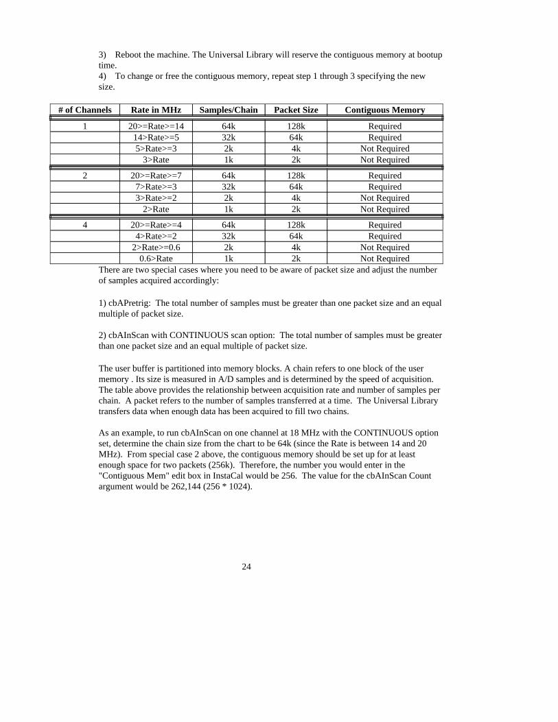
3) Reboot the machine. The Universal Library will reserve the contiguous memory at bootuptime.4) To change or free the contiguous memory, repeat step 1 through 3 specifying the newsize.
Not Required2k1k0.6>RateNot Required4k2k2>Rate>=0.6
Required64k32k4>Rate>=2Required128k64k20>=Rate>=44
Not Required2k1k2>RateNot Required4k2k3>Rate>=2
Required64k32k7>Rate>=3Required128k64k20>=Rate>=72
Not Required2k1k3>RateNot Required4k2k5>Rate>=3
Required64k32k14>Rate>=5Required128k64k20>=Rate>=141
Contiguous MemoryPacket SizeSamples/ChainRate in MHz# of Channels
There are two special cases where you need to be aware of packet size and adjust the numberof samples acquired accordingly:
1) cbAPretrig: The total number of samples must be greater than one packet size and an equalmultiple of packet size.
2) cbAInScan with CONTINUOUS scan option: The total number of samples must be greaterthan one packet size and an equal multiple of packet size.
The user buffer is partitioned into memory blocks. A chain refers to one block of the usermemory . Its size is measured in A/D samples and is determined by the speed of acquisition.The table above provides the relationship between acquisition rate and number of samples perchain. A packet refers to the number of samples transferred at a time. The Universal Librarytransfers data when enough data has been acquired to fill two chains.
As an example, to run cbAInScan on one channel at 18 MHz with the CONTINUOUS optionset, determine the chain size from the chart to be 64k (since the Rate is between 14 and 20MHz). From special case 2 above, the contiguous memory should be set up for at leastenough space for two packets (256k). Therefore, the number you would enter in the"Contiguous Mem" edit box in InstaCal would be 256. The value for the cbAInScan Countargument would be 262,144 (256 * 1024).
24
Analog OutputFunctions: cbAOut(), cbAOutScan()Options: NONEHighChan: 1 maxCount: 2Rate: IgnoredRange: The 4020/12 supports the following Range arguments:
BIP10VOLTS (± 10 volts)BIP5VOLTS (± 5 volts)
Pacing: Software only
Digital I/O
Functions: cbDOut(), cbDIn(), cbDBitIn(), cbDBitOut()PortNum: FIRSTPORTA, FIRSTPORTB, FIRSTPORTCL, FIRSTPORTCHDataValue: 0 to 15 for PORTC, 0 to 255 for FIRSTPORTA or FIRSTPORTBBitNum: 0 to 3 for PORTC, 0 to 7 for FIRSTPORTA or FIRSTPORTB
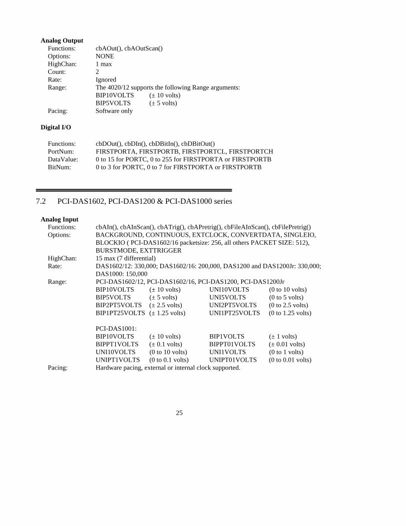
7.2 PCI-DAS1602, PCI-DAS1200 & PCI-DAS1000 series
Analog Input Functions: cbAIn(), cbAInScan(), cbATrig(), cbAPretrig(), cbFileAInScan(), cbFilePretrig()Options: BACKGROUND, CONTINUOUS, EXTCLOCK, CONVERTDATA, SINGLEIO,
BLOCKIO ( PCI-DAS1602/16 packetsize: 256, all others PACKET SIZE: 512),BURSTMODE, EXTTRIGGER
HighChan: 15 max (7 differential)Rate: DAS1602/12: 330,000; DAS1602/16: 200,000, DAS1200 and DAS1200Jr: 330,000;
DAS1000: 150,000Range: PCI-DAS1602/12, PCI-DAS1602/16, PCI-DAS1200, PCI-DAS1200Jr
BIP10VOLTS (± 10 volts) UNI10VOLTS (0 to 10 volts)BIP5VOLTS (± 5 volts) UNI5VOLTS (0 to 5 volts)BIP2PT5VOLTS (± 2.5 volts) UNI2PT5VOLTS (0 to 2.5 volts)BIP1PT25VOLTS (± 1.25 volts) UNI1PT25VOLTS (0 to 1.25 volts)
PCI-DAS1001: BIP10VOLTS (± 10 volts) BIP1VOLTS (± 1 volts) BIPPT1VOLTS (± 0.1 volts) BIPPT01VOLTS (± 0.01 volts) UNI10VOLTS (0 to 10 volts) UNI1VOLTS (0 to 1 volts) UNIPT1VOLTS (0 to 0.1 volts) UNIPT01VOLTS (0 to 0.01 volts)
Pacing: Hardware pacing, external or internal clock supported.
25
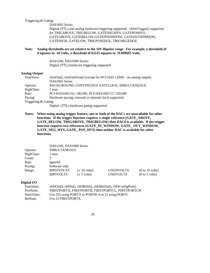
Triggering & Gating: DAS1602 Series:Digital (TTL) and analog hardware triggering supported. cbSetTrigger() supportedfor TRIGABOVE, TRIGBELOW, GATENEGHYS, GATEPOSHYS,GATEABOVE, GATEBELOW,GATEINWINDOW, GATEOUTWINDOW,GATEHIGH, GATELOW, TRIGPOSEDGE, TRIGNEGEDGE
Note: Analog thresholds are set relative to the 10V Bipolar range. For example, a threshold of0 equates to -10 Volts, a threshold of 65535 equates to +9.999695 Volts.
DAS1200, DAS1000 Series:Digital (TTL) hardware triggering supported.
Analog OutputFunctions: cbAOut(), cbAOutScan() (except for PCI-DAS 1200Jr - no analog output)
DAS1602 SeriesOptions: BACKGROUND, CONTINUOUS, EXTCLOCK, SIMULTANEOUSHighChan: 1 maxRate: PCI-DAS1602/16: 100,000, PCI-DAS1602/12: 250,000Pacing: Hardware pacing, external or internal clock supported.Triggering & Gating:
Digital (TTL) hardware gating supported.
Notes: When using analog trigger feature, one or both of the DACs are unavailable for otherfunctions. If the trigger function requires a single reference (GATE_ABOVE,GATE_BELOW, TRIGABOVE, TRIGBELOW) then DAC0 is available. If the trigger function requires two references (GATE_IN_WINDOW, GATE_ OUT_WINDOW,GATE_NEG_HYS, GATE_ POS_HYS) then neither DAC is available for other functions.
DAS1200, DAS1000 SeriesOptions: SIMULTANEOUSHighChan: 1 maxCount: 2Rate: IgnoredPacing: Software onlyRange: BIP10VOLTS (± 10 volts) UNI10VOLTS (0 to 10 volts)
BIP5VOLTS (± 5 volts) UNI5VOLTS (0 to 5 volts)
Digital I/O Functions: cbDOut(), cbDIn(), cbDBitIn(), cbDBitOut(), cbDConfigPort()PortNum: FIRSTPORTA, FIRSTPORTB, FIRSTPORTCL, FIRSTPORTCHDataValue: 0 to 255 using PORTA or PORTB, 0 to 15 using PORTCBitNum: 0 to 23 FIRSTPORTA
26
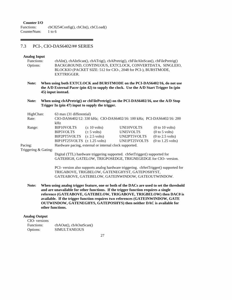
Counter I/OFunctions: cbC8254Config(), cbCIn(), cbCLoad()CounterNum: 1 to 6
7.3 PCI-, CIO-DAS6402/## SERIES
Analog Input Functions: cbAIn(), cbAInScan(), cbATrig(), cbAPretrig(), cbFileAInScan(), cbFilePretrig()Options: BACKGROUND, CONTINUOUS, EXTCLOCK, CONVERTDATA, SINGLEIO,
BLOCKIO (PACKET SIZE: 512 for CIO-, 2048 for PCI-), BURSTMODE,EXTTRIGGER.
Note: When using both EXTCLOCK and BURSTMODE on the PCI-DAS6402/16, do not usethe A/D External Pacer (pin 42) to supply the clock. Use the A/D Start Trigger In (pin45) input instead.
Note: When using cbAPretrig() or cbFilePretrig() on the PCI-DAS6402/16, use the A/D StopTrigger In (pin 47) input to supply the trigger.
HighChan: 63 max (31 differential)Rate: CIO-DAS6402/12: 330 kHz; CIO-DAS6402/16: 100 kHz; PCI-DAS6402/16: 200
kHzRange: BIP10VOLTS (± 10 volts) UNI10VOLTS (0 to 10 volts)
BIP5VOLTS (± 5 volts) UNI5VOLTS (0 to 5 volts)BIP2PT5VOLTS (± 2.5 volts) UNI2PT5VOLTS (0 to 2.5 volts)BIP1PT25VOLTS (± 1.25 volts) UNI1PT25VOLTS (0 to 1.25 volts)
Pacing: Hardware pacing, external or internal clock supported.Triggering & Gating:
Digital (TTL) hardware triggering supported. cbSetTrigger() supported forGATEHIGH, GATELOW, TRIGPOSEDGE, TRIGNEGEDGE for CIO- version.
PCI- version also supports analog hardware triggering. cbSetTrigger() supported forTRIGABOVE, TRIGBELOW, GATENEGHYST, GATEPOSHYST,GATEABOVE, GATEBELOW, GATEINWINDOW, GATEOUTWINDOW.
Note: When using analog trigger feature, one or both of the DACs are used to set the thresholdand are unavailable for other functions. If the trigger function requires a singlereference (GATEABOVE, GATEBELOW, TRIGABOVE, TRIGBELOW) then DAC0 isavailable. If the trigger function requires two references (GATEINWINDOW, GATEOUTWINDOW, GATENEGHYS, GATEPOSHYS) then neither DAC is available forother functions.
Analog OutputCIO- versionsFunctions: cbAOut(), cbAOutScan()Options: SIMULTANEOUS
27
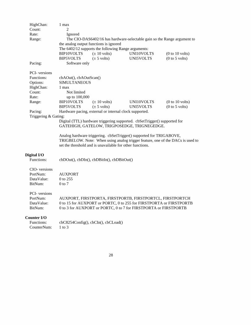
HighChan: 1 maxCount: 2Rate: IgnoredRange: The CIO-DAS6402/16 has hardware-selectable gain so the Range argument to
the analog output functions is ignoredThe 6402/12 supports the following Range arguments:BIP10VOLTS (± 10 volts) UNI10VOLTS (0 to 10 volts)BIP5VOLTS (± 5 volts) UNI5VOLTS (0 to 5 volts)
Pacing: Software only
PCI- versionsFunctions: cbAOut(), cbAOutScan()Options: SIMULTANEOUSHighChan: 1 maxCount: Not limitedRate: up to 100,000Range: BIP10VOLTS (± 10 volts) UNI10VOLTS (0 to 10 volts)
BIP5VOLTS (± 5 volts) UNI5VOLTS (0 to 5 volts)Pacing: Hardware pacing, external or internal clock supported.Triggering & Gating:
Digital (TTL) hardware triggering supported. cbSetTrigger() supported forGATEHIGH, GATELOW, TRIGPOSEDGE, TRIGNEGEDGE.
Analog hardware triggering. cbSetTrigger() supported for TRIGABOVE,TRIGBELOW. Note: When using analog trigger feature, one of the DACs is used toset the threshold and is unavailable for other functions.
Digital I/O Functions: cbDOut(), cbDIn(), cbDBitIn(), cbDBitOut()
CIO- versionsPortNum: AUXPORTDataValue: 0 to 255BitNum: 0 to 7
PCI- versionsPortNum: AUXPORT, FIRSTPORTA, FIRSTPORTB, FIRSTPORTCL, FIRSTPORTCHDataValue: 0 to 15 for AUXPORT or PORTC, 0 to 255 for FIRSTPORTA or FIRSTPORTBBitNum: 0 to 3 for AUXPORT or PORTC, 0 to 7 for FIRSTPORTA or FIRSTPORTB
Counter I/OFunctions: cbC8254Config(), cbCIn(), cbCLoad()CounterNum: 1 to 3
28

7.4 CIO-, PCI- AND PC104- DAS08 SERIES BOARDS
Analog Input Functions: cbAIn(), cbAInScan(), cbATrig()Options: BACKGROUND, CONTINUOUS, EXTCLOCK, CONVERTDATA, SINGLEIO,
EXTTRIGGERHighChan: 7Rate: 50 kHz (See note regarding SINGLEIO at the beginning of the ANALOG INPUT
BOARDS section.Range: DAS08: The DAS08 does not have programmable gain so the Range argument to
analog input functions is ignored.
DAS08-PGH and DAS08-AOH support the following A/D ranges:BIP10VOLTS (± 10 volts) UNI10VOLTS (0 to 10 volts)BIP5VOLTS (± 5 volts) UNI1VOLTS (0 to 1 volts)BIP1VOLTS (± 1 volts) UNIPT1VOLTS (0 to 0.1 volts)BIPPT5VOLTS (± 0.5 volts) UNIPT01VOLTS (0 to 0.01 volts)BIPPT1VOLTS (± 0.1 volts) BIPPT01VOLTS (± 0.01 volts)BIPPT05VOLTS (± 0.05 volts) BIPPT005VOLTS (± 0.005 volts)
CIO-DAS08-PGL and CIO-DAS08-AOL support the following A/D ranges:BIP10VOLTS (± 10 volts) BIP5VOLTS (± 5 volts) BIP2PT5VOLTS (± 2.5 volts) BIP1PT25VOLTS (± 1.25 volts) BIPPT625VOLTS (± 0.625 volts) UNI10VOLTS (0 to 10 volts) UNI5VOLTS (0 to 5 volts) UNI2PT5VOLTS (0 to 2.5 volts) UNI1PT25VOLTS (0 to 1.25 volts)
PCI-DAS08 supports the BIP5VOLTS (± 5 volts) A/D range only.
Pacing: Hardware pacing, external or internal clock supported.Triggering & Gating:
Digital (TTL) polled gate triggering supported.Notes: Before using the timed analog input function cbAInScan() the output of counter 1
must be wired to the Interrupt input or, if you have a DAS08 rev 3 or higher, ajumper is provided on the board to accomplish this. An interrupt level must havebeen selected in InstaCal and the CB.CFG file saved.
Analog Output Functions: cbAOut(), cbAOutScan() (DAS08-AOL, DAS08-AOH & DAS08-AOM only)Options: SIMULTANEOUSHighChan: 1 maxRate: IgnoredCount: 2 maxRange: IgnoredPacing: Software pacing only
29
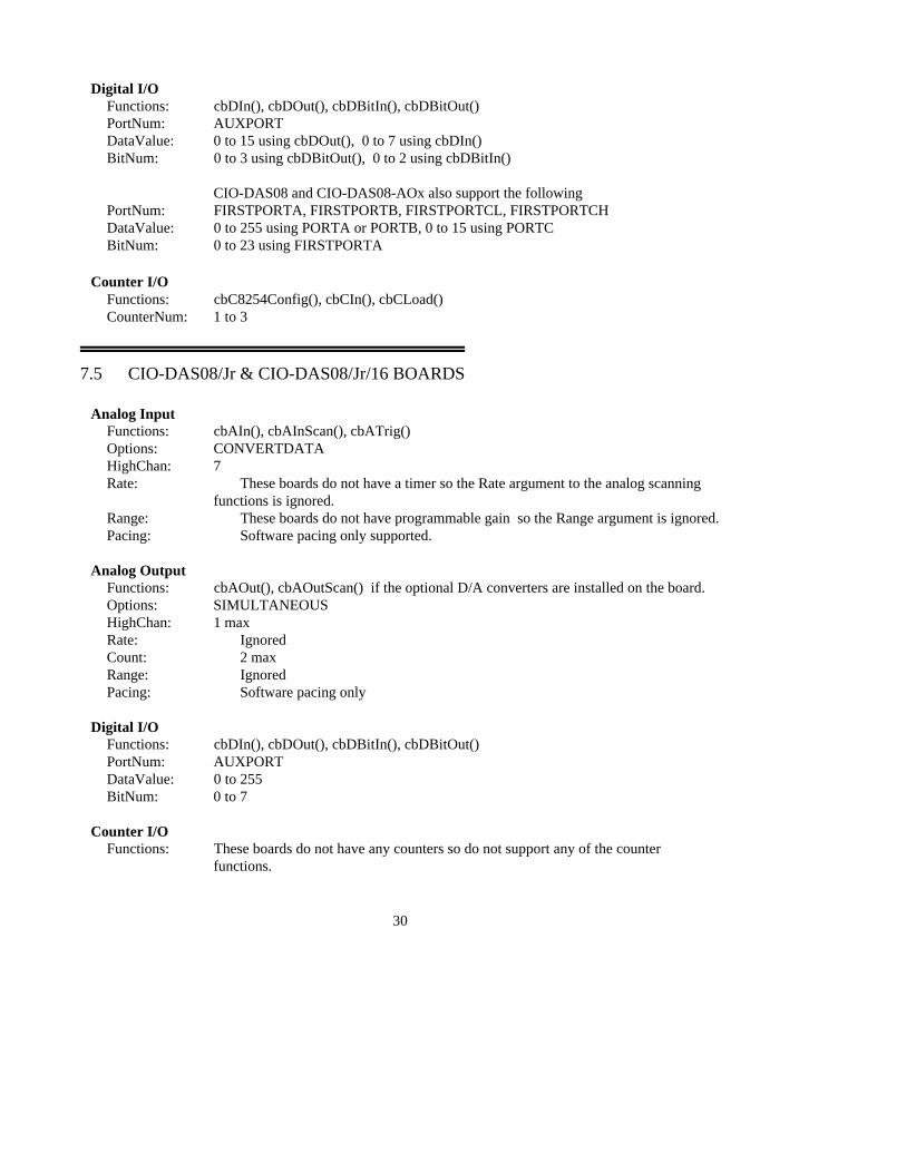
Digital I/O Functions: cbDIn(), cbDOut(), cbDBitIn(), cbDBitOut() PortNum: AUXPORTDataValue: 0 to 15 using cbDOut(), 0 to 7 using cbDIn()BitNum: 0 to 3 using cbDBitOut(), 0 to 2 using cbDBitIn()
CIO-DAS08 and CIO-DAS08-AOx also support the following PortNum: FIRSTPORTA, FIRSTPORTB, FIRSTPORTCL, FIRSTPORTCHDataValue: 0 to 255 using PORTA or PORTB, 0 to 15 using PORTCBitNum: 0 to 23 using FIRSTPORTA
Counter I/O Functions: cbC8254Config(), cbCIn(), cbCLoad()CounterNum: 1 to 3
7.5 CIO-DAS08/Jr & CIO-DAS08/Jr/16 BOARDS
Analog Input Functions: cbAIn(), cbAInScan(), cbATrig()Options: CONVERTDATAHighChan: 7Rate: These boards do not have a timer so the Rate argument to the analog scanning
functions is ignored. Range: These boards do not have programmable gain so the Range argument is ignored.Pacing: Software pacing only supported.
Analog Output Functions: cbAOut(), cbAOutScan() if the optional D/A converters are installed on the board. Options: SIMULTANEOUSHighChan: 1 maxRate: IgnoredCount: 2 maxRange: IgnoredPacing: Software pacing only
Digital I/O Functions: cbDIn(), cbDOut(), cbDBitIn(), cbDBitOut() PortNum: AUXPORTDataValue: 0 to 255BitNum: 0 to 7
Counter I/OFunctions: These boards do not have any counters so do not support any of the counter
functions.
30
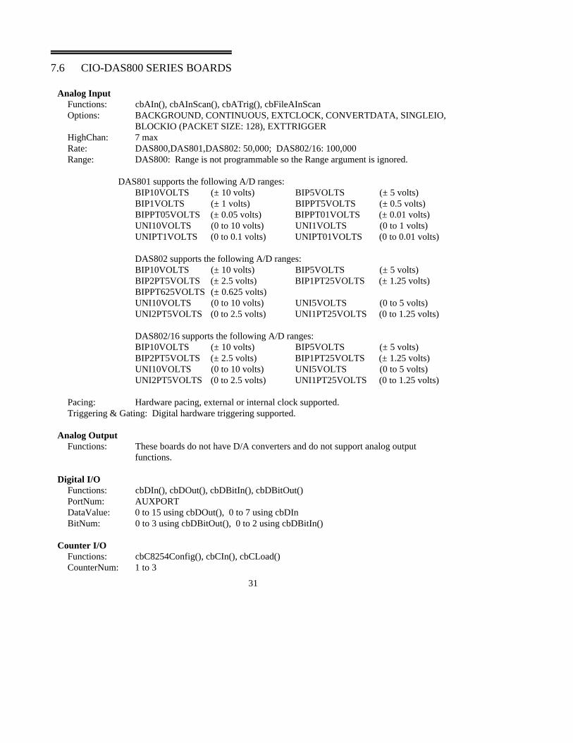
7.6 CIO-DAS800 SERIES BOARDS
Analog Input Functions: cbAIn(), cbAInScan(), cbATrig(), cbFileAInScanOptions: BACKGROUND, CONTINUOUS, EXTCLOCK, CONVERTDATA, SINGLEIO,
BLOCKIO (PACKET SIZE: 128), EXTTRIGGERHighChan: 7 maxRate: DAS800,DAS801,DAS802: 50,000; DAS802/16: 100,000Range: DAS800: Range is not programmable so the Range argument is ignored.
DAS801 supports the following A/D ranges:BIP10VOLTS (± 10 volts) BIP5VOLTS (± 5 volts)BIP1VOLTS (± 1 volts) BIPPT5VOLTS (± 0.5 volts)BIPPT05VOLTS (± 0.05 volts) BIPPT01VOLTS (± 0.01 volts)UNI10VOLTS (0 to 10 volts) UNI1VOLTS (0 to 1 volts)UNIPT1VOLTS (0 to 0.1 volts) UNIPT01VOLTS (0 to 0.01 volts)
DAS802 supports the following A/D ranges:BIP10VOLTS (± 10 volts) BIP5VOLTS (± 5 volts)BIP2PT5VOLTS (± 2.5 volts) BIP1PT25VOLTS (± 1.25 volts)BIPPT625VOLTS (± 0.625 volts)UNI10VOLTS (0 to 10 volts) UNI5VOLTS (0 to 5 volts)UNI2PT5VOLTS (0 to 2.5 volts) UNI1PT25VOLTS (0 to 1.25 volts)
DAS802/16 supports the following A/D ranges:BIP10VOLTS (± 10 volts) BIP5VOLTS (± 5 volts)BIP2PT5VOLTS (± 2.5 volts) BIP1PT25VOLTS (± 1.25 volts)UNI10VOLTS (0 to 10 volts) UNI5VOLTS (0 to 5 volts)UNI2PT5VOLTS (0 to 2.5 volts) UNI1PT25VOLTS (0 to 1.25 volts)
Pacing: Hardware pacing, external or internal clock supported.Triggering & Gating: Digital hardware triggering supported.
Analog OutputFunctions: These boards do not have D/A converters and do not support analog output
functions.
Digital I/O Functions: cbDIn(), cbDOut(), cbDBitIn(), cbDBitOut() PortNum: AUXPORTDataValue: 0 to 15 using cbDOut(), 0 to 7 using cbDInBitNum: 0 to 3 using cbDBitOut(), 0 to 2 using cbDBitIn()
Counter I/O Functions: cbC8254Config(), cbCIn(), cbCLoad()CounterNum: 1 to 3
31
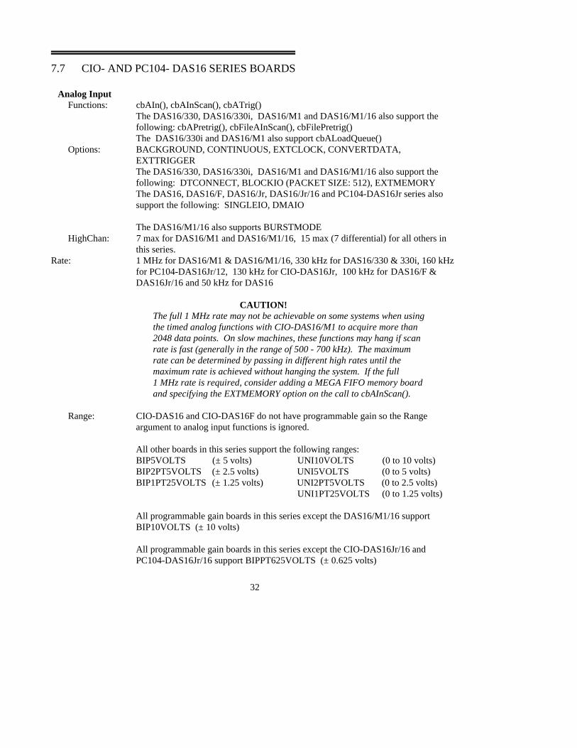
7.7 CIO- AND PC104- DAS16 SERIES BOARDS
Analog Input Functions: cbAIn(), cbAInScan(), cbATrig()
The DAS16/330, DAS16/330i, DAS16/M1 and DAS16/M1/16 also support thefollowing: cbAPretrig(), cbFileAInScan(), cbFilePretrig()The DAS16/330i and DAS16/M1 also support cbALoadQueue()
Options: BACKGROUND, CONTINUOUS, EXTCLOCK, CONVERTDATA, EXTTRIGGERThe DAS16/330, DAS16/330i, DAS16/M1 and DAS16/M1/16 also support the following: DTCONNECT, BLOCKIO (PACKET SIZE: 512), EXTMEMORYThe DAS16, DAS16/F, DAS16/Jr, DAS16/Jr/16 and PC104-DAS16Jr series alsosupport the following: SINGLEIO, DMAIO
The DAS16/M1/16 also supports BURSTMODEHighChan: 7 max for DAS16/M1 and DAS16/M1/16, 15 max (7 differential) for all others in
this series.Rate: 1 MHz for DAS16/M1 & DAS16/M1/16, 330 kHz for DAS16/330 & 330i, 160 kHz
for PC104-DAS16Jr/12, 130 kHz for CIO-DAS16Jr, 100 kHz for DAS16/F &DAS16Jr/16 and 50 kHz for DAS16
CAUTION!The full 1 MHz rate may not be achievable on some systems when usingthe timed analog functions with CIO-DAS16/M1 to acquire more than2048 data points. On slow machines, these functions may hang if scanrate is fast (generally in the range of 500 - 700 kHz). The maximumrate can be determined by passing in different high rates until themaximum rate is achieved without hanging the system. If the full 1 MHz rate is required, consider adding a MEGA FIFO memory boardand specifying the EXTMEMORY option on the call to cbAInScan().
Range: CIO-DAS16 and CIO-DAS16F do not have programmable gain so the Rangeargument to analog input functions is ignored.
All other boards in this series support the following ranges:BIP5VOLTS (± 5 volts) UNI10VOLTS (0 to 10 volts)BIP2PT5VOLTS (± 2.5 volts) UNI5VOLTS (0 to 5 volts)BIP1PT25VOLTS (± 1.25 volts) UNI2PT5VOLTS (0 to 2.5 volts)
UNI1PT25VOLTS (0 to 1.25 volts)
All programmable gain boards in this series except the DAS16/M1/16 support BIP10VOLTS (± 10 volts)
All programmable gain boards in this series except the CIO-DAS16Jr/16 andPC104-DAS16Jr/16 support BIPPT625VOLTS (± 0.625 volts)
32
Pacing: Hardware pacing, external or internal clock supported.Triggering & Gating:
DAS16/M1/16: Digital (TTL) hardware triggering supported. cbSetTrigger()supported for GATEHIGH, GATELOW, TRIGPOSEDGE, TRIGNEGEDGEAll others in this series support digital (TTL) polled gate triggering.
Notes: The DMAIO option can not be used while using the chan/gain queue on the DAS-330iboard.
Analog OutputFunctions: cbAOut(), cbAOutScan() (CIO-DAS16 & CIO-DAS16/F only)Options: SIMULTANEOUSHighChan: 1 maxRate: IgnoredCount: 2 maxRange: IgnoredPacing: Software pacing only
Digital I/OFunctions: cbDIn(), cbDOut(), cbDBitIn(), cbDBitOut()
CIO-DAS16 & 16/F, CIO-DAS16/M1 and CIO-DAS16/M1/16 also supportcbDConfigPort()
PortNum: AUXPORTDataValue: 0 to 15BitNum: 0 to 3
CIO-DAS16 & 16/F, CIO-DAS16/M1 and CIO-DAS16/M1/16 also support FIRSTPORTA, FIRSTPORTB, FIRSTPORTCL, and FIRSTPORTCH.
DataValue: 0 to 255 for PORTA and PORTB, 0 to 15 for PORTCL & PORTCHBitNum: 0 to 23 using FIRSTPORTA
Counter I/OFunctions: cbC8254Config(), cbCIn(), cbCLoad()CounterNum: 1 to 3; CIO-DAS16/M1/16 also supports counter numbers 4 through 6 with counter
4 being the only independent user counter.
7.8 CIO-DAS48/PGA BOARD
Analog Input Functions: cbAIn(), cbAInScan(), cbATrig()Options: CONVERTDATAHighChan: 47 (23 differential)Rate: This board does not have a timer so the Rate argument to the analog scanning
functions is ignored.
Range: The board may be configured with a jumper for either voltage or current input.
33
The voltage input ranges are: BIP10VOLTS (± 10 volts) BIP5VOLTS (± 5 volts) BIP2PT5VOLTS (± 2.5 volts) BIP1PT25VOLTS (± 1.25 volts) BIPPT625VOLTS (± 1.625 volts) UNI10VOLTS (0 to 10 volts) UNI5VOLTS (0 to 5 volts) UNI2PT5VOLTS (0 to 2.5 volts) UNI1PT25VOLTS (0 to 1.25 volts)
The current input ranges are:MA4TO20 (4 to 20ma) MA2TO10 (2 to 10ma)MA1TO5 (1 to 5ma) MAPT5TO2PT5 (0.5 to 2.5ma)
Analog OutputThe CIO-DAS48/PGA board does not support the analog output functions.
Digital I/O The CIO-DAS48/PGA does not support any of the digital I/O functions.
Counter I/O The CIO-DAS48/PGA does not support any of the counter I/O functions.
7.9 CIO-DAS1400 & CIO-DAS1600 SERIES BOARDS
Analog Input Functions: cbAIn(), cbAInScan(), cbATrig()Options: BACKGROUND, CONTINUOUS, EXTCLOCK, CONVERTDATA, SINGLEIO,
DMAIO, BURSTMODE, EXTTRIGGERNote: Specifying SINGLEIO while also specifying BURSTMODE is notrecommended.The CIO-DAS1600 series also supports DTCONNECT & EXTMEMORY
Note: When EXTMEMORY is used with the CIO-DAS1600 the cbGetStatus function will not return the current count and current index. This is a limitation imposed by maintaining identical registers to the KM-DAS1600.
HighChan: 15 max (7 differential)Rate: DAS1401/12, DAS1402/12, DAS1601/12, DAS1602/12: 160 kHz; DAS1602/16,
DAS1402/16: 100 kHzDAS1401/12, DAS1402/12, DAS1601/12, DAS1602/12 to external memory (DTConnect): 330 kHz
Range: CIO-DAS1402, CIO-DAS1602, CIO-DAS1402/16 and CIO-DAS1602/16BIP10VOLTS (± 10 volts) UNI10VOLTS (0 to 10 volts)BIP5VOLTS (± 5 volts) UNI5VOLTS (0 to 5 volts)BIP2PT5VOLTS (± 2.5 volts) UNI2PT5VOLTS (0 to 2.5 volts)BIP1PT25VOLTS (± 1.25 volts) UNI1PT25VOLTS (0 to 1.25 volts)
34
CIO-DAS1401 and CIO-DAS1601BIP10VOLTS (± 10 volts) BIP1VOLTS (± 1 volts) BIPPT1VOLTS (± 0.1 volts) BIPPT01VOLTS (± 0.01 volts) UNI10VOLTS (0 to 10 volts) UNI1VOLTS (0 to 1 volts) UNIPT1VOLTS (0 to 0.1 volts) UNIPT01VOLTS (0 to 0.01 volts)
Note: The CIO-DAS1400 and CIO-DAS1600 A/D ranges are configured with a combination ofa switch (Unipolar / Bipolar) and a programmable gain code. The state of this switch isset in the configuration file using InstaCal. Once the UNI/BIP switch setting is selected,only matching ranges may be used in Universal Library programs.
Pacing: Hardware pacing, external or internal clock supported.Triggering & Gating:
External digital (TTL) polled gate trigger supported.
Analog OutputFunctions: cbAOut(), cbAOutScan() (CIO-DAS1600 series only)Options: SIMULTANEOUSHighChan: 1 maxCount: 2Rate: IgnoredPacing: Software pacing onlyRange: Analog output gain is not programmable so Range argument is ignored.
Digital I/O Functions: cbDOut(), cbDIn(), cbDBitIn(), cbDBitOut()
DAS1600 series also supports cbDConfigPort()PortNum: AUXPORTDataValue: 0 to 15BitNum: 0 to 3
DAS1600 series also supports the following:PortNum: FIRSTPORTA, FIRSTPORTB, FIRSTPORTCL, FIRSTPORTCHDataValue: 0 to 255 using PORTA or PORTB, 0 to 15 using PORTCBitNum: 0 to 23 using FIRSTPORTA
Counter I/OFunctions: cbC8254Config(), cbCIn(), cbCLoad()CounterNum: 1 to 3
7.10 PPIO-AI8
Analog InputFunctions: cbAIn(), cbAInScan(), cbATrig()
35

Options: CONVERTDATAHighChan: 7Rate: IgnoredRange: This board does not have programmable gain so the Range argument to analog input
functions is ignoredPacing: Software pacing
Digital I/OFunctions: cbDIn(), cbDOut(), cbDBitIn(), cbDBitOut() PortNum: AUXPORTDataValue: 0 to 15 using cbDOut(), 0 to 7 using cbDIn()BitNum: 0 to 3 using cbDBitOut(), 0 to 2 using cbDBitIn()
7.11 PCM-DAS08 BOARD
Analog Input Functions: cbAIn(), cbAInScan(), cbATrig()Options: BACKGROUND, CONTINUOUS, EXTCLOCK, CONVERTDATA, SINGLEIO,
NOTODINTS, EXTTRIGGER, NOCALIBRATEDATAHighChan: 7Rate: 24 kHz max (see hardware manual for other restrictions)Range: This board does not have programmable gain so the Range argument to analog input
functions is ignored.Pacing: Internal or external clock
Digital I/OFunctions: cbDIn(), cbDOut(), cbDBitIn(), cbDBitOut() PortNum: AUXPORTDataValue: 0 to 7BitNum: 0 to 2
MAXIMIZING SAMPLING RATES Although the PCM-DAS08 is capable of 25 kHz analog to digital conversions, not allcomputers in all configurations can transfer the converted samples fast enough to sustain a 25kHz sample and transfer rate without missing some samples. This is especially true in aWindows environment. Unfortunately, there isn't much you can do to improve sampling ratesin Windows, but in DOS, where you have more control over process, you may be able toattain the full 25 kHz sampling rate.
Determining Maximum Sampling Rates in DOSIf you have installed the DOS version of the Universal Library, a utility program calledMAXRATE will have been installed in the UL directory (C:\CB by default).
MAXRATE will test your computer and advise you of the maximum sustainable convert andtransfer rate.
36

The maximum rate for your computer will be reported for two conditions. The first is with allinterrupts enabled, the second is with the time of day interrupt disabled (TOD). The convertand transfer rate with TOD disabled will usually be faster.
What has the Time of Day interrupt got to do with A/D conversions?Many TSR’s and device drivers “hook” into the TOD interrupt. Using the TOD clock tickguarantees that every 1/18th of a second the routine will be woken up and can check status ordo whatever the routine is designed to do. Unfortunately this can create considerableoverhead in the TOD interrupt service routine and will introduce gaps in your sample data athigh rates.
Using the cbAinScan0 option argument to turn off the TOD interrupt will increase the speedyou can maintatin with you PCM-DAS08. Turning off the TOD will also prevent yourcomputer’s clock from incrementing while cbAlnScan0 is running. Your clock will lose time.
At what speed might there be a concern with my computer’s transfer rate?Any rate below 5KHz is sustainable with or without TOD interrupt enabled if your maximumrequired rate is less than 5KHz then your computer can do that.
If your required rate is greater that 10K you should run MAXRATE.
Remember, we are discussing the TOTAL rate, not the per channel rate. If you want 3channels at 5 kHz, the total rate is 15 kHz and you should run MAXRATE to see if yourcomputer is up to the task.
What about background operation?MAXRATE tests your computer using the cbAInScan() routine in the foreground. If youchoose background operation it may not sustain the maximum rate returned by MAXRATE.
For the fastest performance use cbAInScan() in the foreground with the TOD interruptdisabled.
7.12 PCM-DAS16x/xx & PC-CARD-DAS16/xx SERIES BOARDS
Analog Input Functions: cbAIn(), cbAInScan(), cbATrig(), cbFileAInScan()Options: BACKGROUND, CONTINUOUS, EXTCLOCK, CONVERTDATA, SINGLEIO,
BLOCKIO (packet size: 256 for ), NOTODINTS, EXTTRIGGER,NOCALIBRATEDATA
HighChan: 15 (16S and 16/330), 7 (16D)Rate: 330 kHz for 16/330, 200 kHz single channel for PC-CARD-DAS16/16 series, 100
kHz for all others in this seriesRange: The DAS16x/12 boards support the following A/D ranges:
BIP10VOLTS (± 10 volts) UNI10VOLTS (0 to 10 volts)
37
BIP5VOLTS (± 5 volts) UNI5VOLTS (0 to 5 volts)BIP2PT5VOLTS (± 2.5 volts) UNI2PT5VOLTS (0 to 2.5 volts)BIP1PT25VOLTS (± 1.25 volts) UNI1PT25VOLTS (0 to 1.25 volts)
The DAS16x/16 boards support the following A/D ranges:BIP10VOLTS (± 10 volts) BIP5VOLTS (± 5 volts)BIP2PT5VOLTS (± 2.5 volts) BIP1PT25VOLTS (± 1.25 volts)The DAS16/330 board supports the following A/D ranges:BIP10VOLTS (± 10 volts) BIP5VOLTS (± 5 volts)
Pacing: Internal or external clockTriggering & Gating:
External digital (TTL) polled gate trigger supported on the PCM versions.External digital (TTL) hardware trigger supported on the PC-CARD versions.
Analog Output PCM-DAS16D/12AO and PC-CARD-DAS16/xx-AO onlyFunctions: cbAOut(), cbAOutScan()Options: SIMULTANEOUS (PCM version only)HighChan: 1 maxCount: 2Rate: IgnoredRange: PC-CARD-DAS16/16-AO & PCM-DAS16D/12AO: BIP10VOLTS (± 10 volts),
BIP5VOLTS (± 5 volts)PC-CARD-DAS16/16-AO: BIP10VOLTS (± 10 volts)
Pacing: Software pacing only
Digital I/O PCM-DAS16D/12-AO
Functions: cbDOut(), cbDIn(), cbDBitIn(), cbDBitOut(), cbDConfigPort()PortNum: FIRSTPORTA, FIRSTPORTBDataValue: 0 to 15 using PORTA or PORTBBitNum: 0 to 7 using FIRSTPORTA
PC-CARD-DAS16/xx-AOFunctions: cbDOut(), cbDIn(), cbDBitIn(), cbDBitOut(), cbDConfigPort()PortNum: FIRSTPORTADataValue: 0 to 15 using PORTABitNum: 0 to 3 using FIRSTPORTA
Counter I/O Functions: cbC8254Config(), cbCIn(), cbCLoad()CounterNum: 1 to 3
38

7.13 CIO- & PCI-DAS-TC, CIO-DAS-TEMP
Temperature Input Functions: cbTIn(), cbTInScan()Options: NOFILTERScale: CELSIUS, FARENHEIT, KELVINHighChan: 0 to 15 for DAS-TC, 0 to 31 for DAS-TEMP
Note: When using cbTInScan() with the DAS-TC, an open thermocouple error(OPENCONNECTION) on any of the channels will cause all data to be returned as-9999.0. This is a hardware limitation. If your application requires isolating channelswith defective thermocouples attached and returning valid data for the remainder of thechannels, use the cbTIn() function instead of cbTInScan().
39
8.0 DIGITAL INPUT / OUTPUT
This chapter provides details on using ComputerBoards digital I/O boards in conjunction with the UniversalLibrary. Boards released after the printing of this manual will be described in readme files on the UniversalLibrary disk.
Note on Basic signed integers: When reading or writing ports that are 16 bits wide, you should be aware ofthe following issues using signed integers (as you are forced to do when using Basic): On some boards (thePDISO16 for example) the AUXPORT digital ports are set up as one 16 bit port. When using cbDOut(),the digital values are written as a single 16 bit word. Using signed integers, writing values above 01111111 1111 1111 (32767 decimal) can be confusing. Then next increment, 1000 0000 0000 0000 has adecimal value of -32768. Using signed integers, this is the value that you would use for turning on the MSBonly. The value for all bits on is -1. Keep this in mind if you are using Basic, since Basic does not supplyunsigned integers (values from 0 to 65536).
8.1 CIO-, PCI-, PC-CARD-, PC104- & PPIO- DIO SERIES BOARDS, CIO- &PCI-DUAL-AC5
Digital I/OFunctions: cbDOut(), cbDIn(), cbDBitIn(), cbDBitOut(), cbDConfigPort()
All boards in this series support:PortNum: FIRSTPORTA, FIRSTPORTB, FIRSTPORTCL and FIRSTPORTCH. DataValue: 0 to 255 using PORTA or PORTB, 0 to 15 using PORTCL or PORTCHBitNum: 0 to 23 using FIRSTPORTA
DIO48, DIO48H, DIO96, DIO192 and DUAL-AC5 also support: PortNum: SECONDPORTA, SECONDPORTB, SECONDPORTCL, SECONDPORTCH DataValue: 0 to 255 using PORTA or PORTB, 0 to 15 using PORTCL or PORTCHBitNum: 0 to 47 using FIRSTPORTA
DIO96 and DIO192 also support: PortNum: THIRDPORTA, THIRDPORTB, THIRDPORTCL, THIRDPORTCH,
FOURTHPORTA, FOURTHPORTB, FOURTHPORTCL, FOURTHPORTCHDataValue: 0 to 255 using PORTA or PORTB, 0 to 15 using PORTCL or PORTCHBitNum: 0 to 95 using FIRSTPORTA
DIO192 also supports: PortNum: FIFTHPORTA through EIGHTHPORTCHDataValue: 0 to 255 using PORTA or PORTB, 0 to 15 using PORTCL or PORTCHBitNum: 0 to 191 using FIRSTPORTA
40

8.2 CIO- AND PCM- DIO24/CTR3, PC-CARD-D24/CTR3
Digital I/OFunctions: cbDOut(), cbDIn(), cbDBitIn(), cbDBitOut(), cbDConfigPort()PortNum: FIRSTPORTA, FIRSTPORTB, FIRSTPORTCL and FIRSTPORTCH. DataValue: 0 to
255 using PORTA or PORTB, 0 to 15 using PORTCL or PORTCHBitNum: 0 to 23 using FIRSTPORTA
Counter I/O Functions: cbC8254Config(), cbCIn(), cbCLoad()CounterNum: 1 to 3Note: On the PCM board the counter source functions are programmable using InstaCal.
8.3 PCI-DIO48H/CTR15
Digital I/OFunctions: cbDOut(), cbDIn(), cbDBitIn(), cbDBitOut(), cbDConfigPort()PortNum: FIRSTPORTA, FIRSTPORTB, FIRSTPORTC, FIRSTPORTCH. SECONDPORTA,SECONDPORTB, SECONDPORTCL, SECONDPORTCH. DataValue: 0 to 255 using PORTA orPORTB, 0 to 15 using PORTCL or PORTCHBitNum: 0 to 23 using FIRSTPORTA
Counter I/O Functions: cbC8254Config(), cbCIn(), cbCLoad()CounterNum: 1 to 15
8.4 CIO-, PC104-, AND PCI- PDISO8 AND PDISO16
Digital I/OFunctions: cbDIn(), cbDOut(), cbDBitIn(), cbDBitOut() PortNum: AUXPORTDataValue: PDISO8: 0 to 255, PDISO16: 65535 (see note on Basic signed integers at the beginning
of the DIGITAL INPUT / OUTPUT section)BitNum: PDISO8: 0 to 7, PDISO16: 0 to 15
41

8.5 CIO-PDMA16 AND CIO-PDMA32
Digital I/OFunctions: cbDInScan(), cbDOutScan(), cbDIn(), cbDOut(), cbDBitIn(), cbDBitOut(),
cbDConfigPort()PortNum: AUXPORT, FIRSTPORTA, and FIRSTPORTB.DataValue: 0 to 7 using AUXPORT (cbDOut() only supported), 0 to 255 using PORTA and
PORTB, 0 to 65535 using WORDXFER PORTA.BitNum: 0 to 2 using AUXPORT (cbDBitOut() only supported), 0 to 15 using PORTA.
Rate: CIO-PDMA16: 125 KWords, CIO-PDMA32: 750 KWords
Options: BACKGROUND, CONTINUOUS, EXTCLOCK, WORDXFER
Pacing: Hardware pacing, external or internal clock supported.
Counter I/OFunctions: cbC8254Config(), cbCIn(), cbCLoad()CounterNum: 1 to 3
42

9.0 DIGITAL INPUT
This chapter provides details on using ComputerBoards digital input boards in conjunction with theUniversal Library. Boards released after the printing of this manual will be described in readme files on theUniversal Library disk.
9.1 CIO- AND PC104- DIxx SERIES BOARDS
Digital I/OFunctions: cbDIn, cbDBitIn()
All boards in this series support:PortNum: FIRSTPORTA, FIRSTPORTB, FIRSTPORTCL and FIRSTPORTCH. DataValue: 0 to 255 using PORTA or PORTB, 0 to 15 using PORTCL or PORTCHBitNum: 0 to 23 using FIRSTPORTA
DI48, DI96 and DI192 also support:PortNum: SECONDPORTA, SECONDPORTB, SECONDPORTCL, SECONDPORTCH DataValue: 0 to 255 using PORTA or PORTB, 0 to 15 using PORTCL or PORTCHBitNum: 0 to 47 using FIRSTPORTA
DI96 and DI192 also support: PortNum: THIRDPORTA, THIRDPORTB, THIRDPORTCL, THIRDPORTCH,
FOURTHPORTA, FOURTHPORTB, FOURTHPORTCL, FOURTHPORTCHDataValue: 0 to 255 using PORTA or PORTB, 0 to 15 using PORTCL or PORTCHBitNum: 0 to 95 using FIRSTPORTA
DI192 also supports: PortNum: FIFTHPORTA through EIGHTHPORTCHDataValue: 0 to 255 using PORTA or PORTB, 0 to 15 using PORTCL or PORTCHBitNum: 0 to 191 using FIRSTPORTA
9.2 CIO-DISO48 BOARDS
Digital I/OFunctions: cbDIn, cbDBitIn()PortNum: FIRSTPORTA, SECONDPORTA, THIRDPORTA, FOURTHPORTA, FIFTHPORTA,
SIXTHPORTADataValue: 0 to 255BitNum: 0 to 7 using FIRSTPORTA
43

10.0 DIGITAL OUTPUT
This chapter provides details on using ComputerBoards digital output boards in conjunction with theUniversal Library. Boards released after the printing of this manual will be described in readme files on theUniversal Library disk.
10.1 CIO-RELAY SERIES
Digital I/OFunctions: cbDOut(), cbDBitOut()
All boards in this series support:PortNum: FIRSTPORTADataValue: 0 to 255BitNum: 0 to 7 using FIRSTPORTA
CIO-RELAY16 & 16/M also support:PortNum: FIRSTPORTBDataValue: 0 to 255BitNum: 0 to 15 using FIRSTPORTA
CIO-RELAY24 also supports:PortNum: SECONDPORTADataValue: 0 to 255BitNum: 0 to 23 using FIRSTPORTA
CIO-RELAY32 also supports:PortNum: SECONDPORTBDataValue: 0 to 255BitNum: 0 to 31 using FIRSTPORTA
10.2 CIO- AND PC104-, DO## AND DO##DD SERIES
Digital I/OFunctions: cbDOut(), cbDBitOut()
All boards in this series support:PortNum: FIRSTPORTA, FIRSTPORTB, FIRSTPORTCL and FIRSTPORTCH. DataValue: 0 to 255 using PORTA or PORTB, 0 to 15 using PORTCL or PORTCHBitNum: 0 to 23 using FIRSTPORTA
44

DO48H, DO48DD, DO96H and DO192H also support:PortNum: SECONDPORTA, SECONDPORTB, SECONDPORTCL, SECONDPORTCH DataValue: 0 to 255 using PORTA or PORTB, 0 to 15 using PORTCL or PORTCHBitNum: 0 to 47 using FIRSTPORTA
DO96H and DO192H also support: PortNum: THIRDPORTA, THIRDPORTB, THIRDPORTCL, THIRDPORTCH,
FOURTHPORTA, FOURTHPORTB, FOURTHPORTCL, FOURTHPORTCHDataValue: 0 to 255 using PORTA or PORTB, 0 to 15 using PORTCL or PORTCHBitNum: 0 to 95 using FIRSTPORTA
DO192H also supports: PortNum: FIFTHPORTA through EIGHTHPORTCHDataValue: 0 to 255 using PORTA or PORTB, 0 to 15 using PORTCL or PORTCHBitNum: 0 to 191 using FIRSTPORTA
45
11.0 COUNTER BOARDS
This chapter provides details on using ComputerBoards counter/timer boards in conjunction with theUniversal Library. Boards released after the printing of this manual will be described in readme files on theUniversal Library disk.
Note on Basic signed integers: When reading or writing ports that are 16 bits wide, you should be aware ofthe following issues using signed integers (as you are forced to do when using Basic): On some boards (theCIO-CTR10 count register or AUXPORT digital ports for example) the ports are 16 bits wide. Whenaccessing the data at these ports, the digital values are arranged as a single 16 bit word. Using signedintegers, values above 0111 1111 1111 1111 (32767 decimal) can be confusing. Then next increment,1000 0000 0000 0000 has a decimal value of -32768. Using signed integers, this is the value that isreturned from a 16 bit counter at half of maximum count. The value for full count (just before the counterturns over) is -1. Keep this in mind if you are using Basic, since Basic does not supply unsigned integers(values from 0 to 65535) or unsigned longs (values from 0 to 4,294,967,295).
11.1 CIO-, PCI-, PC104- AND cSBX CTR SERIES
Counter I/OFunctions: cbC9513Config(), cbC9513Init(), cbCStoreOnInt(), cbCFreqIn(), cbCIn(), cbCLoad()
ALL BOARDS in this series support:CounterNum: Counters 1 to 5RegName: LOADREG1 through LOADREG5, HOLDREG1 through HOLDREG5,
ALARM1CHIP1 and ALARM2CHIP1LoadValue: Values up to 65,535 (216 - 1) may be used. (See note on Basic signed integers at the
beginning of the COUNTER BOARDS section.)
CTR10, CTR10-HD and CTR20-HD also supportCounterNum: Counters 6 through 10RegName: LOADREG6 through LOADREG10, HOLDREG6 through HOLDREG10,
ALARM1CHIP2 and ALARM2CHIP2
CTR20-HD also supports CounterNum: Counters 11 through 20RegName: LOADREG11 through LOADREG20, HOLDREG11 through HOLDREG20,
ALARM1CHIP3 and ALARM2CHIP3, ALARM1CHIP4 and ALARM2CHIP4
46
Digital I/OCTR05 and CTR10 support:Functions: cbDIn(), cbDOut(), cbDBitIn(), cbDBitOut() PortNum: AUXPORTDataValue: CTR05: 0 to 255, CTR10: 0 to 65535 (See note on Basic signed integers at the
beginning of the COUNTER BOARDS section.)BitNum: CTR05: 0 to 7, CTR10: 0 to 15
11.2 CIO-, AND PCI- INT32
Counter I/OFunctions: cbC8536Config(),cbC8536Init(), cbCIn(), cbCLoad()CounterNum: 1 to 6ChipNum: 1 or 2RegName: LOADREG1 through LOADREG6LoadValue: Values up to 65,535 (216 - 1) may be used. (See note on Basic signed integers at the
beginning of the COUNTER BOARDS section.)Note: These boards have two 8536 chips, which have both counter and digital I/O and
interrupt vectoring capabilities. The numbers above apply when both chips are configured for the maximum number of counter devices.
Digital I/OFunctions: cbDIn(), cbDOut(), cbDBitIn(), cbDBitOut() PortNum: FIRSTPORTA, FIRSTPORTB, FIRSTPORTCL, SECONDPORTA, SECONDPORTB
and SECONDPORTCL.DataValue: 0 to 255 using PORTA or PORTB, 0 to 15 using PORTCLBitNum: 0 to 39 using FIRSTPORTANote: These boards have two 8536 chips, which have both counter and digital I/O and interrupt
vectoring capabilities. The numbers above apply when both chips are configured for the maximum number of digital ports.
47
11.3 PPIO-CTR06 BOARDS
Counter I/OFunctions: cbC8254Config(), cbCIn(), cbCLoad()CounterNum: 1 to 6RegName: LOADREG1 through LOADREG6LoadValue: Values up to 65,535 (216 - 1) may be used. (See note on Basic signed integers at the
beginning of the COUNTER BOARDS section.)
Digital I/OFunctions: cbDIn(), cbDOut(), cbDBitIn(), cbDBitOut() PortNum: AUXPORTDataValue: 0 to 15 or 0 to 255, depending on jumper settingBitNum: 0 to 3 or 0 to 7, depending on jumper setting
11.4 CIO- PCI- AND PCM- QUAD SERIES
Counter I/OFunctions: cb7266Config(), cbCIn, cbCIn32, cbLoad, cbLoad32, cbCStatus()CounterNum: 1 to 2 - PCM-QUAD02, CIO-QUAD02
1 to 4 - CIO-QUAD04, PCI-QUAD04RegName: COUNT1, COUNT2, PRESET1, PRESET2, PRESCALER1 , PRESCALER2
CIO-QUAD04, PCI-QUAD04 also support COUNT3, COUNT4, PRESET3, PRESET4,PRESCALER3, PRESCALER4
LoadValue: When using cbCLoad32() to load the COUNT# or PRESET# registers, values up to 16.78million (224 - 1) may be loaded. Values using cbCLoad() are limited to 65,535 (216 - 1).(See note on Basic signed integers at the beginning of the COUNTER BOARDS section.)When loading the PRESCALER# register, values may be from 0 to 255. (Digital FilterClock frequency = 10 MHz / LoadValue + 1.)
48

12.0 EXPANSION BOARDS
This chapter provides details on using ComputerBoards expansion boards in conjunction with the UniversalLibrary. Boards released after the printing of this manual will be described in readme files on the UniversalLibrary disk.
EXP boards are only used in combination with an A/D board. Channel numbers for accessing theEXPansion boards begin at 16. To calculate the channel number for access to EXP channels, use thefollowing formula:
Chan = (ADChan + 1) * 16 + EXPChan
where EXPChan is a number ranging from 0 to 15 that describes the channel number on a particular bank ofthe expansion board. An EXP32 has two banks so the channel numbers for one EXP32 connected to anA/D board would range from 16 to 47.
If all A/D channels are not used for EXP output, direct input to the A/D board is still available at thesechannels (using channel numbers below 16).
When expansion boards are used for temperature input, the gain of the A/D board must be set to a specificrange. When using A/D boards with programmable gain, the Universal Library takes care of this detail.However, when using boards with switch-selectable gains, they should be set by the user to a range thatdepends on the temperature sensor in use. Generally, thermocouple measurements require the A/D board tobe set to 5V bipolar if available (or 10V bipolar if not). RTD sensors require a setting of 10V unipolar ifavailable. These checks are made when you are configuring the system for temperature measurement usingInstacal.
12.1 CIO-EXP SERIES BOARDS
Analog Input Functions: cbAIn(),cbTIn(), cbTInScan()Options: NOFILTERHighChan: From 0 up to 255, depending on the number of boards connected and the application.Rate: This board does not have a timer so the Rate argument to the analog scanning functions is
ignored. Range: This argument applies to the A/D board to which the EXP board is connected. It is
ignored if the A/D board does not have programmable gain (see ANALOG INPUTBOARDS section)
49
12.2 MEGA-FIFO BOARD
Memory I/O (Used only in combination with a board which has DT-Connect.)Functions: cbMemSetDTMode(), cbMemReset(), cbMemRead(), cbMemWrite(),
cbMemReadPretrig()
Some of these functions are integrated into the cbAInScan() function. For example, if the MEGA-FIFO isused with an A/D board and the EXTMEMORY option is selected then the functions cbMemSetDTMode()and cbMemWrite() would not have to be called. Continuous-mode cannot be used with the EXTMEMORYoption.
13.0 METRABUS BOARDS
This chapter provides details on using ComputerBoards MetraBus system boards in conjunction with theUniversal Library. The MetraBus system is made up of at least one controller board that communicates withreal world interface boards via a data bus (ribbon cable). The implication is that there will always be two ormore boards in the system.
13.1 ISA-, PCI- and PC104-MDB64 SERIES BOARDS
This series makes up the controller portion of the MetraBus system. The Universal Library contains nofunction to communicate specifically with this board. The functions in the library are directed to thedevices on the bus, instead. For example, if this board was installed in Instacal as board 0, and an MII-32was installed as board 1, the communication would be directed to board 1. If you wanted to read digital bitsfrom this configuration, the function would be cbDBitIn(). The value of the BoardNum argument would be1.
13.2 MIO-32
Digital I/OFunctions: cbDIn(), cbDOut(), cbDBitIn(), cbDBitOut() PortNum: FIRSTPORTA, FIRSTPORTB, SECONDPORTA, SECONDPORTBDataValue: 0 to 255BitNum: 0 to 7Note: Although this is a digital output only board, the state of the outputs can be read back using thecbDIn() and cbDBitIn() functions.
50
13.3 MII-32
Digital I/OFunctions: cbDIn(), cbDBitIn()PortNum: FIRSTPORTA, FIRSTPORTB, SECONDPORTA, SECONDPORTBBitNum: 0 to 7
13.4 MEM-8
Digital I/OFunctions: cbDIn(), cbDOut(), cbDBitIn(), cbDBitOut() PortNum: FIRSTPORTADataValue: 0 to 255BitNum: 0 to 7
Note: Although this is a digital output only board, the state of the outputs can be read back using thecbDIn() and cbDBitIn() functions.
13.5 MEM-32
Digital I/OFunctions: cbDIn(), cbDOut(), cbDBitIn(), cbDBitOut() PortNum: FIRSTPORTA, FIRSTPORTB, SECONDPORTA, SECONDPORTBDataValue: 0 to 255BitNum: 0 to 7
Note: Although this is a digital output only board, the state of the outputs can be read back using thecbDIn() and cbDBitIn() functions.
13.6 MSSR-24
Digital I/OFunctions: cbDIn(), cbDOut(), cbDBitIn(), cbDBitOut() PortNum: FIRSTPORTA, FIRSTPORTB, SECONDPORTADataValue: 0 to 255BitNum: 0 to 7
51
14.0 OTHER FUNCTIONS
14.1 CIO- AND PCM- COM 422
No library functions are supported for these boards, but Instacal may be used to configure the serialprotocol in conjunction with the Set422.exe utility. All other serial communications are handled by DOS orWindows standard serial communications handlers.
14.2 CIO- AND PCM- COM 485
Supports cbRS485() for controlling the transmit and receive enable register. All other serial communicationsare handled by DOS or Windows standard serial communications handlers.
14.3 DEMO-BOARD
The DEMO-BOARD is a software simulation of a data acquisition board. It simulates analog input anddigital I/O.
Analog InputFunctions: cbAIn(), cbAInScan(), cbATrig(), cbFileAInScan()Options: BACKGROUND, CONTINUOUS, SINGLEIO, DMAIO HighChan: 7 max Rate: 300000
DEMO-BOARD simulates 8 channels of 16-bit analog input. Instacal is used to configure the waveforms onthe analog input channels. Choices are: sine wave, square wave, saw-tooth, ramp, damped sine wave, andinput from a data file.
The data file is a streamer file, so any data that has been previously saved in a streamer file can be used as asource of demo data by the board. Data files are named DEMO0.DAT through DEMO7.DAT. When a datafile is assigned to a channel the library will try to extract data for that channel from the streamer file. If datafor that channel does not exist, then the first (and possibly only) channel data in the streamer is extractedand used. For example, if DEMO2.DAT is assigned as the data source for the demo board's channel 5, thenthe library will try to extract data from the file corresponding to channel 5. DEMO2.DAT may have scandata corresponding to channels 0 through 15, and if so then channel 5 is extracted. Or, DEMO2.DAT mayhave data for a single channel, say 3. If so, then that data is used for the demo board's channel 5.
52

Digital I/O Functions: cbDIn(), cbDBitIn(), cbDInScan(), cbDOut(), cbDBitOut(), cbDOutScan(),cbDConfigPort(),PortNum: FIRSTPORTA, FIRSTPORTB, AUXPORTDataValue: 0 to 255 using PORTA, PORTB, or AUXPORTBitNum: 0 to 15 FIRSTPORTA
DEMO-BOARD simulates:one 8-bit AUXPORT non-configurable digital input port. Each bit of the AUXPORT generates asquare wave with a different period. one 8-bit AUXPORT non-configurable digital output port. two 8-bit configurable digital I/O ports - FIRSTPORTA, FIRSTPORTB - which can be used forhigh speed scanning. FIRSTPORTA functions like AUXPORT in that it generates square waves.Each bit of FIRSTPORTB generates a pulse with a different frequency.
53

15.0 APPENDIX A. ERROR CODES
Each entry in the list has four parts. The error code number, it's symbolic name, it's error message, and aexplanation.
# SYMBOLIC_NAME Error messageDescription
0 NOERRORS No error has occurred. The function executed successfully
1 BADBOARD Invalid board number.The board number that was specified does not match any of the boards that are listed in the configurationfile. Run the configuration program to check which board numbers are configured.
2 DEADDIGITALDEV Digital device is not responding - is base address correct?The digital device on the specified board is not responding. Either the board was installed incorrectly or theboard is defective. Run the configuration program and make sure that the correct board was installed.
3 DEADCOUNTERDEV Counter device is not responding - is base address correct?The counter device on the specified board is not responding. Either the board was installed incorrectly orthe board is defective. Run the configuration program and make sure that the correct board was installed.
4 DEADDADEV D/A is not responding - is base address correct?The D/A device on the specified board is not responding. Either the board was installed incorrectly or theboard is defective. Run the configuration program and make sure that the correct board was installed.
5 DEADADDEV A/D is not responding - is base address correct?The A/D device on the specified board is not responding. Either the board was installed incorrectly or theboard is defective. Run the configuration program and make sure that the correct boards was installed.
6 NOTDIGITALCONF Selected board does not have digital I/O.A digital I/O function was called with a board number that referred to a board that does not support digitalI/O. Run the configuration program to see which type of board that board number refers to.
7 NOTCOUNTERCONF Selected board does not have a counter.A counter function was called with a board number that referred to a board that does not have a counter.Run the configuration program to see which type of board that board number refers to.
8 NOTDACONF Selected board does not have a D/A.An analog output function was called with a board number that referred to a board that does not have ananalog output (D/A). Run the configuration program to see which type of board that board number refersto.
54
9 NOTADCONF Selected board does not have an A/D.An analog input function was called with a board number that referred to a board that does not have ananalog input (A/D). Run the configuration program to see which type of board that board number refersto.
10 NOTMUXCONF Selected board does not have thermocouple inputs.A thermocouple input function was called with a board number that does not support thermocouple inputsor is not connected to an EXP board. Run the configuration program to view/change the boardconfiguration.
11 BADPORTNUM Invalid digital port number.The Port number that was specified for a digital I/O function does not exist on the board that was specified.
12 BADCOUNTERDEVNUM Invalid counter device.The Counter Number that was specified for a counter function does not exist on the board that wasspecified.
13 BADDADEVNUM Invalid D/A device.The D/A channel that was specified for an analog output function does not exist on the board that wasspecified.
14 BADSAMPLEMODE Invalid sample mode.A sample mode that is not supported on this board (SINGLEIO, DMAIO or BLOCKIO) was specified inthe Options argument. Try running the function without setting any of the Sample Mode options.
15 BADINT Board configured for invalid interrupt level.No interrupt was selected in InstaCal and one is required, or the board is set for “compatible mode” and theinterrupt level selected is not supported in this mode. Interrupts above 7 are not valid in compatible mode.Either change the switch setting on the board to “enhanced mode”, or change the interrupt level with theconfiguration program to something less than 8.
16 BADADCHAN Invalid A/D channel number.An invalid channel argument was passed to an analog input function. The range of valid channel numbersdepends on which A/D board you are using - refer to the board manual. For some boards it also dependson how the board is configured (with a switch). For those boards run the configuration program and checkhow many channels the board is configured for.
17 BADCOUNT Invalid count.An invalid Count argument was specified to a function.
18 BADCNTRCONFIG Invalid counter configuration specified.An invalid Config argument was passed to cbC8254Config. The only legal values areHIGHONLASTCOUNT, ONESHOT, RATEGENERATOR, SQUAREWAVE, SOFTWARESTROBEand HARDWARESTROBE.
19 BADDAVAL Invalid D/A value.
55

An invalid D/A value was passed as an argument to an analog output function. The only legal values are 0- 4095 for 12 bit boards or 0-65,535 for 16 bit boards (see notes on signed integers).
20 BADDACHAN Invalid D/A channel number.An inavlid D/A channel was passed as an argument to an analog output function. The legal range of valuesdepends on which D/A board you are using. Refer to the board manual to find how many D/A channels ithas.
22 ALREADYACTIVE Background operation already in progress.An attempt was made to start a second background process on the same board before the first one hadcompleted. Background processes are started whenever the BACKGROUND option is used or by thecbCStoreOnInt function. To stop a background operation call cbStopBackground(). To wait for abackground process to complete call cbGetStatus() and wait for status=IDLE.
23 PAGEOVERRUN DMA transfer crossed page boundary, may have gaps in data.When a DMA transfer crosses a 64K memory page boundary on boards without FIFO buffers, there may bea small gap (missing samples) in the data. For applications requiring high speed transfers of greater than32K samples, please select a board with a FIFO buffer. For boards without, check the data for gaps and donot specify rates over that at which gapless data may be taken. This is system specific and you mustdetermine the rate by experimentation.
24 BADRATE Invalid sampling rate.Invalid sampling rate argument was specified. The rate was either zero, a negative number or it was higherthan the selected board supports. Refer to board specific information for maximum rates for each board.
25 COMPATMODE Board switches set for Compatible mode.An operation was attempted that is not possible when the board's switch is set for 'compatible' operation.Most likely causes are using the BLOCKIO option or the pre-triggering functions. Either turn off the'compatible' mode switch on the board or don't use the BLOCKIO option or the pre-triggering functions.
26 TRIGSTATE Incorrect initial trigger state - trigger must start at TTL low.Boards that use “polled gate” triggering require that the trigger be "off" when a pre-trigger functions is firstcalled. It then waits for the trigger signal. Make sure that the Trigger Input line (usually D0) is held at TTL low before calling the pre-trigger function.
27 ADSTATUSHUNG A/D is not responding.The A/D board is not responding as it should. Usually indicates some kind of hardware problem - eitherdefective hardware or more than one board at the same base address.
28 TOOFEW Trigger occurred before requested number of samples were collected.A pre-trigger function was called and the trigger signal occurred before the requested number of samplescould be collected. This is only a warning message. The function continued anyway. The data that wasreturned to the array will contain fewer than the expected number of points. The function will return theactual number of pre-trigger points and the total number of points. You can use these two values to findyour way around the data in the array.
56
29 OVERRUN Data overrun - data was lost.Data was lost during an analog input because the computer could not keep up with the A/D sampling rate.This typically can only happen with the file input functions or using SINGLIO mode. Possible solutions include lowering the sampling rate, defragmenting the "streamer" file, switching to a RAM disk, orlowering the count.
30 BADRANGE Invalid voltage or current range..Invalid Range argument was specified to an analog input or output function. The board does not support the gain you specified. Refer to board specific information for a list of allowable ranges for each board.
31 NOPROGGAIN This A/D board does not have programmable gain.Invalid Range argument was passed to an analog input function. The selected board does not supportprogrammable gains so the only valid Range argument is 0.
32 BADFILENAME Specified file name is not valid'.The FileName argument that was passed to a file function is not valid. It is either an empty string or aNULL pointer.
33 DISKISFULL Disk is full, could not complete operation.A file operation failed before completing because the disk that it was writing to is full. Try erasing somefiles from the disk. If this error occurred during either cbFileAInScan() or cbFilePretrig() it indicatesanother problem. The disk space for these commands should have been previously allocated with theMAKESTRM.EXE program. If this error is generated when data is being collected it indicates that you didnot allocate a large enough file with MAKESTRM.EXE.
34 COMPATWARN Board switch set to compatible mode - sampling speed may be limited.The board's switch is set for 'Compatible mode". When in "compatible mode" BLOCKIO transfers are notpossible. BLOCKIO sampling was specified but it has automatically been changed to DMAIO transfers.The maximum sampling rate will be limited to the maximum rate for DMA transfers. Change the"compatible mode" switch on the board if you want to use BLOCKIO transfers.
35 BADPOINTER Pointer is not valid.An invalid (NULL) pointer was passed as an argument to a function.
37 RATEWARNING Sample rate may be too fast for SINGLEIO mode.The specified sampling rate MAY be too high. The maximum allowable sampling rate depends very muchon the computer that the program is running on. This warning is generated based on the slowest CPUspeed. Your computer may be able to sustain faster rates, but, you should expect the computer to lock up(fail to respond to keyboard input) if you do exceed the sampling rate your computer can sustain.
38 CONVERTDMA CONVERTDATA cannot be used with DMA I/O and BACKGROUND.The CONVERTDATA and BACKGROUND options can not be used together when the board istransferring data via DMA. Possible solutions include: Use cbAConvertData() to convert the data after itis collected. Don't use BACKGROUND option. Use BLOCKIO Option if your A/D board supports it.Use SINGLEIO Option if your computer is fast enough to support the selected sampling rate.
39 DTCONNECTERR Board does not support DTCONNECT option.
57

The DTCONNECT Option was passed to an analog input function. The selected board does not supportthat option.
40 FORECONTINUOUS CONTINUOUS can only be run with BACKGROUND.The CONTINUOUS Option was passed to a function without also setting the BACKGROUND Option.This is not allowed. Any time you set the CONTINUOUS Option you must also set the BACKGROUND option.
41 BADBOARDTYPE This function can not be used with this board'An attempt was made to call a function for a board that does not support that function.
42 WRONGDIGCONFIG Digital port not configured correctly for requested operation.Some of the digital ports (FIRSTPORTA - EIGHTHPORTCH) must be configured as inputs OR outputsbut not both. An attempt was made to use a digital input function on a port that was configured as anoutput or vice versa. Use cbDConfigPort() to switch a port's direction. If the board you are using containsthese port types and you do not call cbDConfigPort() in your program then all of the configurable ports willbe in an unknown state (input or output).
43 NOTCONFIGURABLE This digital port is not configurable (it’s an In/Out port).cbDConfigPort() was called for a port that is not configurable. Check the Port Number argument passed tocbDConfigPort() and make sure that it is in the range FIRSTPORTA - EIGHTHPORTCH. If not thenthere is no need to call this function.
44 BADPORTCONFIG Invalid digital port configuration.The Direction argument passed to cbDConfigPort() is invalid. It must be set to either DIGITALIN orDIGITALOUT.
45 BADFIRSTPOINT First point number is not valid.The First Point argument to cbReadFile() is invalid. It is either a negative number or it is larger then thenumber of points in the file.
46 ENDOFFILE Attempted to read past the end of the file.cbFileRead() attempted to read beyond the end of the file. Check the file length with cbFileGetInfo() andmake sure that the First Point and Count arguments to cbFileRead() are correct for that file length.
47 NOT8254CTR This board does not have an 8254 counter.The cbC8254Config() function was called for a board that has a counter but not an 8254 counter. Thisfunction can only be used with an 8254.
48 NOT9513CTR This board does not have a 9513 counter.A function was called for a board that has a counter but not a 9513 counter. This function can only be usedwith an 9513.
49 BADTRIGTYPE Invalid TrigType.cbATrig() was called with an invalid TrigType argument. It must be set to either TRIGABOVE orTRIGBELOW.
58
50 BADTRIGVALUE Invalid TrigValue.cbATrig() was called with an invalid TrigValue argument. It must be in the range 0 - 4095 for 12 bitboards or 0 to 65535 for 16 bit boards (see notes on signed integers).
52 BADOPTION Invalid option specified for this function.The Option argument contains an option that is not valid for this function.
53 BADPRETRIGCOUNT Invalid PreTrigCount specified.Either cbAPretrig() or cbFilePretrig() was called with an invalid preTrigCount argument. The pre-triggercount must not be < 0 and must be less then TotalCount - 512. It also must be less than 32k forcbAPretrig() and less than 16k for cbFilePretrig().
55 BADDIVIDER Invalid Fout Divider value.The Fout Divider argument to cbC9513Init() is not valid. It must be in the range 0 - 15.
56 BADSOURCE Invalid Fout Source value.The Source argument to cbC9513Init() is not valid. It must be one of the following values CTRINPUT1,CTRINPUT2, CTRINPUT3, CTRINPUT4, CTRINPUT5, GATE1, GATE2, GATE3, GATE4, GATE5,FREQ1, FERQ2, FREQ3, FREQ4, FREQ5 (i.e. 0 - 15)
57 BADCOMPARE Invalid compare value.One or both of the compare arguments to cbC9513Init() are not valid. They must be set to ENABLED orDISABLED (1 or 0).
58 BADTIMEOFDAY Invalid Time Of Day value.The TimeOfDay argument to cbC9513Init() is not valid. It must be set to either ENABLED orDISABLED (1 or 0).
59 BADGATEINTERVAL Invalid Gate Interval value.The GateInterval argument to cbCFreqIn() is not valid. It must be greater than 0.
60 BADGATECNTRL Invalid Gate Control value.The GateControl argument to cbC9513Config() is not valid. It must be in the range 0 -7.
61 BADCOUNTEREDGE Invalid Counter Edge valueThe CounterEdge argument to cbC9513Config() is not valid. It must be set to either POSITIVEEDGE orNEGATIVEEDGE.
62 BADSPCLGATE Invalid Special Gate value.The SpecialGate argument to cbC9513Config() is not valid. It must be set to either ENABLED orDISABLED (1 or 0).
63 BADRELOAD Invalid Reload value.The Reload argument to cbC9513Config() is not valid. It must be set to either LOADREG orLOADANDHOLDREG
64 BADRECYCLEFLAG Invalid Recycle Mode value.
59

The RecycleMode argument to cbC9513Config() is not valid. It must be set to either ENABLED orDISABLED (1 or 0).
65 BADBCDFLAG Invalid BCD Mode value.The BCDMode argument to cbC9513Config() is not valid. It must be set to either ENABLED orDISABLED (1 or 0).
66 BADDIRECTION Invalid Count Direction value.The CountDirection argument to cbC9513Config() is not valid. It must be set to either COUNTUP orCOUNTDOWN.
67 BADOUTCONTROL Invalid Output Control value.The OutputControl argument to cbC9513Config() is not valid. It must be set to either ALWAYSLOW,HIGHPULSEONTC, TOGGLEONTC, DISCONNECTED or LOWPULSEONTC.
68 BADBITNUMBER Invalid Bitnum specified.The BitNum argument to cbDBitIn() or cbDBitOut() is not valid. The valid range of bit numbers dependson the selected board. If it is a DIO24 compatible board the maximum bit number is 23. If it's a DIO96,the maximum bit number is 95. (See board specific information.)
69 NONEENABLED None of the counter channels were enabled.None of the counter channels were marked as ENABLED in the CntrCntrl array that was passed tocbCStoreOnInt(). At least one of the counter channels must be enabled.
70 BADCTRCONTROL An element of Cntr Control array not set to DISABLED or ENABLED.One of the elements of the CntrControl array that was passed to cbCStoreOnInt() was set to somethingother then ENABLED or DISABLED. The array must have at least ten elements and the first tenelements must be set to either ENABLED or DISABLED.
71 BADEXPCHAN Invalid EXP channel specified.An invalid channel was passed to one of the thermocouple input commands. The channel number whenusing an EXP board must be >= 16. The maximum allowable channel number depends on which EXPboard is being used (and how many of them). Refer to the board manual to find the number of channels.
72 WRONGADRANGE Board set to wrong A/D range for reading thermocouples.A thermocouple input function was called to read an EXP board input. The EXP board is connected to anA/D board with hardware-selected gain that is set to the wrong range. When using EXP boards withthermocouples, the A/D must be set to the -5 to +5 volt range when available. When using RTD sensors,the range is 0 to 10V when available.
73 OUTOFRANGE Temperature input is out of range.A thermocouple input function returned an invalid temperature. This usually indicates an open connectionin the thermocouple or its connection to the EXP board.
74 BADTEMPSCALE Invalid temperature scale specified.The Scale argument to a thermocouple input function is not valid. It must be set to either CELSIUS,FAHRENHEIT or KELVIN.
60

76 NOQUEUE Specified board does not have channel/gain queue.The function that was called requires that the board has a channel/gain queue. The specified board doesnot have a queue.
77 CONTINUOSCOUNT Count must be > packet size to use recycle modeThe count argument is not valid for continuous mode. Using BLOCKIO mode, the Count argument must belarge enough to cause at least one interrupt. This is usually half the size of the boards FIFO (typical sizesare 256, 512 and 1024). See board specific information for details.
78 UNDERRUN D/A FIFO went empty during output.The specified D/A output rate could not be sustained. This error should not normally occur.
79 BADMEMMODE Invalid memory mode specified.The memory mode that was selected with cbMemSetDTMode() is not one of the valid modes.
80 FREQOVERRUN Measured frequency too high for selected gating interval.The gating interval used with cbFreqIn() is too long to measure the frequency of the signal connected to thecounter. The counter is overflowing. Decrease the gating interval to eliminate the error.
81 NOCJCCHAN A CJC Channel must be configured to make temperaturemeasurements.When the board was installed (with the InstaCal installation program) no CJC channel was selected. Touse the temperature measurement functions with thermocouples you must first select a CJC channel on theA/D board and then rerun the installation program.
82 BADCHIPNUM Invalid Chipnum specified.An invalid ChipNum argument was used with the cbC9513Init() function. If the board is CTR05 thenChipNum should be set to 0. If it is a CTR10, ChipNum should be either 0 or 1.
83 DIGNOTENABLED The digital I/O on this board is not enabled.When the board was installed (with the InstaCal installation program), the expansion digital I/O was set toDISABLED. To use these digital I/O lines you must enable the digital I/O on the board (with a jumper)and then re-run the installation program and set the digital I/O to ENABLED.
84 CONVERT16BITS CONVERT option can not be used with 16 bit A/D converters.When using a 16 bit A/D (DAS1600/16), if you try to use the CONVERT option with cbAInScan() or call cbAConvertData() you will get this error.
85 NOMEMBOARD The EXTMEMORY option requires that a MEGA-FIFO be attached..Attempt to use a cbMem() function without a MEGA-FIFO board installed. Install MEGA-FIFO throughInstaCal.
86 DTACTIVE No memory read/write allowed while DT transfer in progress.A read or write to a memory board was attempted while data was being transferred via DT Connect.
61
87 NOTMEMCONF Specified board is not a memory board.The specified board is not a memory board. This function only works with memory boards.
88 ODDCHAN The first channel in scan and number of channels must be even (0, 2, 4, etc).Some boards use a channel/gain queue that require the first channel in the queue and the number ofchannels in the queue always be an even channel. This error can occur even when you are not in theprocess of loading the queue. Some boards use the queue automatically with cbAInScan(). On thoseboards the low channel must be an even number.
89 CTRNOINIT Counter was not configured or initialized.You attempted to use cbCLoad() or cbCIn() before inititalizing and configuring the counter.
90 NOT8536CTR This board does not have an 8536 counter chip.Attempt to use 8536 initialization or configuration on board without 8536 chip.
91 FREERUNNING Board doesn't time A/D sampling. Collecting at fastest possible speed.This board does not have an A/D pacer mechanism and you have called the function cbAInScan(). The A/Dwill be sampled in a tight software loop as fast as the CPU can execute the instructions. The speed ofsampling is dependent on the computer and the concurrent tasks.
92 INTERRUPTED Operation interrupted with Ctrl-C key.A foreground operation was stopped before completion because either the Ctrl-C or Ctrl-Break keys werepressed.
93 NOSELECTORS No selector could be allocated.A Windows selector required by the library could not be allocated. Close any unneeded open Windowsapplications and try again.
94 NOBURSTMODE This board does not support burst mode.An attempt was made to use the BURSTMODE option on a board which does not support that option.
95 NOTWINDOWSFUNC This function is not available in Windows library.The library function you called is not supported in the current revision of Universal Library for WindowsLanguages. It may be supported in the future. Please call.
96 NOTSIMULCONF Board not configured for SIMULTANEOUS option.The configuration file of the D/A board in InstaCal must be set for simultaneous update before you use theSIMULTANEOUS option of cbAOutScan() function. The jumpers on the D/A board must be set forsimultaneous update before it will work.
97 EVENODDMISMATCH An even channel is in an odd slot in the queue, or vice versa.The channel gain queue on some A/D boards has a restriction that the channel numbers must be in evenqueue positions and odd channel numbers must be in odd queue positions.
98 M1RATEWARNING Sampling speed to system memory MAY be too fast.The A/D board sampling speed you have requested may be too fast for the computer system bus transfer tocomplete before the next packet is ready for transfer. If this is the case, data will overrun and sample data
62

will be garbled. This warning is initiated whenever you request a sample rate over 625 KHz AND thesample set is larger than the FIFO buffer on the board AND an external memory board, such as aMEGA-FIFO is not being used. Your system may be able to handle the rate requested but onlyexperimentation will bear this out. Your system may be capable of the full 1 MHz rate directly to systemmemory.
99 NOTRS485 Selected board is not a RS-485 boardAn attempt was made to call cbRS485() with a board that is not RS485 compatible.
100 NOTDOSFUNC This function not available in DOS The function that was called is not available in the DOS version of the Universal Library.
101 RANGEMISMATCH Bipolar and unipolar ranges cannot be used together in A/D queue. The channel/gain queue should only be loaded (via cbALoadQueue()) with all unipolar or bipolar ranges
102 CLOCKTOOSLOW Sampling rate is too high for clockspeed, change clock jumper on board. The sampling rate that you requested is too fast. The A/D board pacer might be capable of running at ahigher rate. Check the board for an XTAL jumper and, if it is not set for the highest rate, place the jumperin the position for the highest rate. Once the jumper is set, re-run InstaCal.
103 BADCALFACTORS Calibration factors are invalid - Disabling software calibrationThe selected board uses software calibration and the stored calibration factors are invalid. Run InstaCal andcalibrate the board before using it.
104 BADCONFIGTYPE Invalid configuration information type specifiedAn invalid ConfigType argument was passed to either cbGetConfig() or cbSetConfig().
105 BADCONFIGITEM Invalid configuration item specifiedAn invalid ConfigItem argument was passed to either cbGetConfig() or cbSetConfig().
106 NOPCMCIABOARD Cannot access the PCMCIA boardCannot access the specified PCMCIA board. Make sure that the PCMCIA Card & Socket Services areinstalled correctly and that the board was installed in the system correctly via InstaCal.
107 NOBACKGROUND Board does not support background operationThe BACKGROUND option was used and the specified board does not support background operation.
108 STRINGTOOSHORT The string argument is too short for the string being returnedThe string passed to a library function is to small to contain the string that is being returned. Increase thesize of the string to the minimum size specified for the function that you are using.
109 CONVERTEXTMEM CONVERTDATA not allowed with EXTMEMORY optionYou requested both the CONVERTDATA and EXTMEMORY option. These options can not be usedtogether. Collect the data without the CONVERTDATA option. Once the data has been collected thenread it back from the memory card (cbMemRead() or cbMemReadPretrig()) and use the cbAConvertData()function to convert the data.
63
110 BADEUADD Program error - bad values used in cbFromEngUnits or cbToEngUnitsInvalid floating point data was used in cbFromEngUnits or cbToEngUnits. Check the arguments passed tothe relevant function.
111 DAS16JRRATEWARNING Rates greater than 125 kHz must use on board 10 MHz clock.If a rate greater than 125KHz is selected and the on board jumper is set for 1 MHz when using theCIO-DAS16/Jr, this warning is generated. Place the jumper on the 10 MHz position and update yourInstaCal settings.
112 DAS08TOOLOW_RATE The desired sample rate is below hardware minimumIncrease the value of the Rate argument in cbAInScan(). The lowest pacer frequency is the clock frequency(usually 8 MHz / 2) divided by 65535 for the CIO-, PC104 and PCM- DAS08.
114 AMBIGSENSORONGP More than one temperature sensor type defined for EXP-GPThermocouple and RTD types are both defined for an EXP-GP. The cbTIn() and cbTInScan() functionsrequire that only one be defined to operate. Set one of the sensor types to "Not Installed" within theappropriate Instacal menu.
115 NOSENSORTYPEONGP No temperature sensor type defined for EXP-GPNeither Thermocouple nor RTD types are defined for an EXP-GP. The cbTIn() and cbTInScan() functionsrequire that one and only one be defined to operate. Set one of the sensor types to a predefined type withinthe appropriate Instacal menu.
116 NOCONVERSIONNEEDED Selected 12 bit board already returns converted dataSome 12 bit boards do not need to have their data converted after a call to cbAInScan() with theNOCONVERTDATA option. These boards return no channel tags and therefore return data in its properformat. Calling cbAConvertData() with data generated from these boards will generate this warning.
117 NOEXTCONTINUOUS CONTINUOUS mode cannot be used with EXTMEMORYCONTINUOUS mode is ignored when used with the EXTMEMORY option.
118 INVALIDPRETRIGCONVERT cbAConvertPretrigData called after cbAPretrig failedThe data you are attempting to convert with cbAConvertPretrigData() can not be converted because thecbAPretrig() function did not return a complete data set - probably due to an early trigger.
119 BADCTRREG Bad counter argument passed to cbCLoadThe RegName argument passed to cbCLoad is not a valid register.
120 BADTRIGTHRESHOLD Low trigger threshold is greater than high thresholdThe LowThreshold arguments to cbSetTrigger() must be less than the HighThreshold
121 BADPCMSLOT NO PCM Card was found in the specified slotThis is usually caused by swapping PCMCIA cards and not re-running InstaCal. Please run InstaCal.
64

122 AMBIGPCMSLOTREF Two identical PCM cards found. Please specify exact slot in Instacal.This error occurs in DOS mode only when InstaCal is configured for a PCMCIA card in "any slot". Tocorrect the problem, run InstaCal. Go to the Install menu and pop up the board's menu. Highlight PCMCIAslot and choose either "0" or "1".
123 BADSENSORTYPEInvalid sensor type selected in InstacalThe specified sensor type is not part of the allowed list of thermocouple/RTD types. Set the sensor type toa predefined type within the appropriate InstaCal menu.
126 CFGFILENOTFOUND Cannot find CB.CFG fileThe CB.CFG file could not be found. This file should be located in the same directory that you installed thesoftware in.
127 NOVDDINSTALLED The CBUL.386 virtual device driver is not installedThe Windows device driver CBUL.386 is not installed on your system. Normally, it will be automaticallyinstalled when you run the ComputerBoards standard installation program. The following line should be inyour \windows\system.ini file in the [386Enh] section. device=c:\cb\cbul.386
128 NOWINDOWSMEMORY Requested amount of Windows page-locked memory is not availableThe Windows device driver could not allocate the required amount of physical memory. This error shouldnot normally occur unless you are collecting very large amounts of data or your system is very memoryconstrained. If you are collecting a very large block of memory, try collecting a smaller amount. If this isnot an option, than consider using cbFileAscan() instead of cbAInScan(). Also, if you are running otherprograms, try shutting them down.
129 OUTOFDOSMEMORY Not enough DOS memory availableTry closing down any unneeded programs that are running
130 OBSOLETEOPTION Obsolete option specified for cbSetConfig/cbGetConfigThe specified configuration item is no longer supported in the 32 bit version of the Universal Library.
131 NOPCMREGKEY No registry entry for this PCMCIA cardWhen running under Windows/NT, there must be an entry in the system registry for each PCMCIA cardthat you will be using with the system. This is ordinarily taken care of automatically by the UniversalLibrary installation program. If this error occurs, call ComputerBoards Technical Support department forassistance.
132 NOCBUL32SYS CBUL32.SYS device driver is not installedThe Windows device driver CBUL.SYS is not installed on your system. Normally, it will be automaticallyinstalled when you run the ComputerBoards standard installation program. Call ComputerBoardsTechnical Support dept. for assistance.
133 NODMAMEMORY No DMA memory available to device driverThe Windows device driver could not allocate the minimum required amount of memory for DMA. If youare sampling at slower speeds, you can specify SINGLEIO in the Options argument to cbAInScan(). This
65

will prevent the library from attempting to use DMA. In general though, this error should not ordinarilyoccur. Please contact ComputerBoards Technical Support Dept with the details
134 IRQNOTAVAILABL E IRQ not availableThe Interrupt Level that was specified for the board (in InstaCal) conflicts with another board in yourcomputer. Try switching to a different interrupt level.
135 NOT7266CTR “This board does not have an LS7266 counter” This function can only be used with a board that contains an LS7266 chip. These chips are used on variousquadrature encoder input boards.
136 BADQUADRATURE “ Invalid Quadrature argument passed to cbC7266Config()”The Quadrature argument must be set to either NO_QUAD, X1_QUAD, X2_QUAD or X4_QUAD
137 BADCOUNTMODE “ Invalid CountingMode argument passed tocbC7266Config()”The CountingMode argument must be set to either NORMAL_MODE, RANGE_LIMIT, NO_RECYCLEor MODULO_N.
138 BADENCODING “ Invalid DataEncoding argument passed to cbC7266Config()”The DataEncoding argument must be set to either BCD_ENCODING or BINARY_ENCODING.
139 BADINDEXMODE “ Invalid IndexMode argument passed to cbC7266Config()”The IndexMode argument must be set to either INDEX_DISABLED, LOAD_CTR, LOAD_OUT_LATCHor RESET_CTR
140 BADINVERTINDEX “ Invalid InvertIndex argument passed to cbC7266Config()”The InvertIndex argument must be set to either ENABLED or DISABLED.
141 BADFLAGPINS “ Invalid FlagPins argument passed to cbC7266Config()”The FlagPins argument must be set to either CARRY_BORROW, COMPARE_BORROW,CARRYBORROW_UPDOWN or INDEX_ERROR
142 NOCTRSTATUS “This board does not support cbCStatus()”This board does not return any status information.
143 NOGATEALLOWED “Gating may not be used when indexing is enabled”Gating and indexing can not be used simultaneously. If Gating is set to ENABLED then IndexMode mustbe set to INDEX_DISABLED.
144 NOINDEXALLOWED “Indexing not allowed in non-quadratue mode” Indexing is not supported when Quadrature arg is set to NON_QUAD.
145 OPENCONNECTION “Temperature input has open connection” A thermocouple being measured may have broken.
146 BMCONTINUOUSCOUNT “Count must be an integer multiple of packet size for recycle mode”
66

Increase the Count value to the packet size or remove the CONTINUOUS option.
147 BADCALLBACKFUNC “Invalid pointer to callback function passed as argument” Find the correct pointer to your callback function (for example, using the AddressOf() function)
148 MBUSINUSE “MetraBus is busy”Wait for completion of activity on bus.
149 MBUSNOCTLR “MetraBus I/O card has no configured controller”Run Instacal configuration program and install a MetraBus controller card (such as the ISA-MDB64)
200-299 Internal error occurred in library - contact ComputerBoards
300-399 Internal error occurred in 32-bit Windows library - contact ComputerBoardsif the error you receive is not detailed below
304 CFG_FILE_READ_FAILURE Error reading from configuration file.The program was unable to read configuration file cb.cfg. Confirm that cb.cfg was not deleted, moved, orrenamed since the software installation.
305 CFG_FILE_WRITE_FAILURE Error writing to configuration file.The program was unable to write to the configuration file cb.cfg. Confirm that cb.cfg is present and that itsattributes are not set for Read-only. Also, check that not more than one application is trying to access thisfile.
308 CFGFILE_CANT_OPEN Cannot open configuration file.The program was unable to open the configuration file cb.cfg. Confirm that cb.cfg was not deleted, moved,or renamed since the software installation.
325 BAD_RTD_CONVERSION Overflow of RTD conversion.Either cbTIn() or cbTInScan() returned an invalid temperature conversion. Confirm that the configurationmatches the RTD type, and physical EXP board settings; pay particular attention to gain settings and RTDbase resistance. Also, check that the RTD leads are securely attached to the EXP terminals. Finally,confirm that the board is measuring reasonable voltages via cbAIn().
326 NO_PCI_BIOS PCI BIOS not present on the PC.Could not locate the BIOS for the PCI bus. Consult PC supplier for proper installation of the PCI BIOS.
327 BAD_PCI_INDEX Specified PCI board not detected.The specified PCI board was not detected. Check that PCI board in securely installed into PCI slot. Also,run Instacal to locate/set valid base address and configuration. 328 NO_PCI_BOARD Specified PCI board not detected.The specified PCI board was not detected. Check that PCI board in securely installed into PCI slot. Also,run Instacal to locate/set valid base address and configuration.
67

334 CANT_INSTALL_INT Cannot install interrupt handler. IRQ already in use.The device driver could not enable requested interrupt. Check that the selected IRQ is not already in use byanother device. This error can also occur if a FOREGROUND scan was aborted; in such cases, rebootingthe PC will correct the problem.
400-499 PCMCIA Card & Socket Service error - contact Computerboards
500-599 Internal DOS error - contact ComputerBoards
600-699 Internal Windows error - contact ComputerBoards if the error you receive is notdetailed below.
603 WIN_CANNOT_ENABLE_INT Cannot enable interrupt. IRQ already in use.The device driver could not enable requested interrupt. Check that the selected IRQ is not already in use byanother device. This error can also occur if a FOREGROUND scan was aborted; in such cases, rebootingthe PC will correct the problem.
605 WIN_CANNOT_DISABLE_INT Cannot disable interrupts.The device driver was unable to disable the IRQ. This can occur when interrupts are generated too fast forthe PC to complete servicing. For example, sampling at high frequencies (above ~2 kHz) with scan modeset for SINGLEIO can lead to this error. Frequently, an OVERRUN error accompanies this condition.
606 WIN_CANT_PAGE_LOCK_BUFFER Insufficient memory to page lock data buffer.There is not enough physical memory to lock down the entire data buffer. Try closing out otherapplications, selecting smaller data buffers, or installing additional RAM.
630 NO_PCM_CARD PCM card not detected.The specified PCMCIA card was not detected. Confirm that the PCM card is securely plugged into
PCMCIA slot. If the board continues to return this error, run Instacal to reset the configuration.
68

For your notes.

ComputerBoards16 Commerce Blvd
Middleboro, MA 02346Tel: (508) 946-5100Fax: (508) 946-9500
E-mail: [email protected]