Embed Size (px)
Citation preview
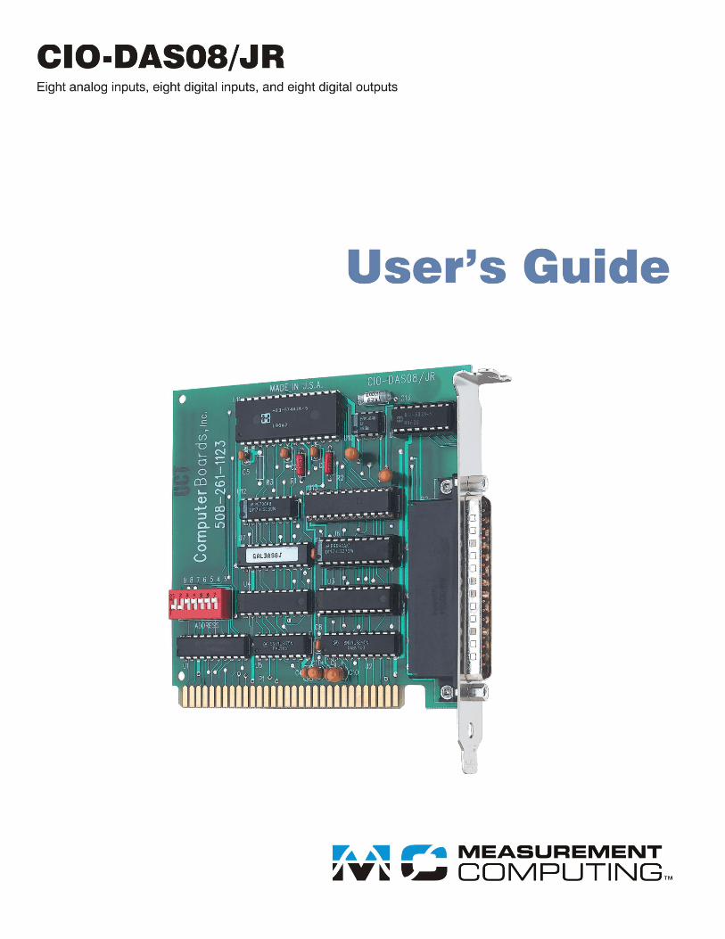
CIO-DAS08/JR
Analog and Digital I/O
User’s Guide
Document Revision 5A, January, 2011 © Copyright 2011, Measurement Computing Corporation
3 HM CIO-DAS08_JR.doc
Trademark and Copyright InformationMeasurement Computing Corporation, InstaCal, Universal Library, and the Measurement Computing logo are either trademarks or registered trademarks of Measurement Computing Corporation. Refer to the Copyrights & Trademarks section on mccdaq.com/legal for more information about Measurement Computing trademarks. Other product and company names mentioned herein are trademarks or trade names of their respective companies.
© 2011 Measurement Computing Corporation. All rights reserved. No part of this publication may be reproduced, stored in a retrieval system, or transmitted, in any form by any means, electronic, mechanical, by photocopying, recording, or otherwise without the prior written permission of Measurement Computing Corporation.
NoticeMeasurement Computing Corporation does not authorize any Measurement Computing Corporation product for use in life support systems and/or devices without prior written consent from Measurement Computing Corporation. Life support devices/systems are devices or systems that, a) are intended for surgical implantation into the body, or b) support or sustain life and whose failure to perform can be reasonably expected to result in injury. Measurement Computing Corporation products are not designed with the components required, and are not subject to the testing required to ensure a level of reliability suitable for the treatment and diagnosis of people.

4
5
Table of Contents
Preface
About this User's Guide ....................................................................................................................... 6
What you will learn from this user's guide ......................................................................................................... 6
Conventions in this user's guide ......................................................................................................................... 6
Where to find more information ......................................................................................................................... 6
Chapter 1
Introducing the CIO-DAS08/JR ............................................................................................................ 7
Overview: CIO-DAS08/JR features ................................................................................................................... 7
Software features ................................................................................................................................................ 7
Chapter 2
Installing the CIO-DAS08/JR ................................................................................................................ 8
What comes with your CIO-DAS08/JR shipment? ............................................................................................ 8 Hardware .......................................................................................................................................................................... 8
Additional documentation .................................................................................................................................. 8
Optional components .......................................................................................................................................... 8
Unpacking the CIO-DAS08/JR .......................................................................................................................... 9
Installing the software ........................................................................................................................................ 9
Configuring the CIO-DAS08/JR ........................................................................................................................ 9
Installing the CIO-DAS08/JR ........................................................................................................................... 10
Connecting the board for I/O operations .......................................................................................................... 10 Connectors, cables – main I/O connector ........................................................................................................................10
Field wiring, signal termination, and conditioning ..........................................................................................................11
Calibrating the CIO-DAS08/JR ........................................................................................................................ 12
Chapter 3
Specifications ...................................................................................................................................... 13
Analog input ..................................................................................................................................................... 13
Digital input/output .......................................................................................................................................... 13
Power consumption .......................................................................................................................................... 13
Environmental .................................................................................................................................................. 14
Main connector and pin out .............................................................................................................................. 14 Declaration of Conformity .................................................................................................................. 15
6
Preface
About this User's Guide
What you will learn from this user's guide
This user's guide explains how to install, configure, and use the CIO-DAS08/JR. This user's guide also refers
you to related documents available on our web site, and to technical support resources.
Conventions in this user's guide
The following conventions are used in this manual to convey special information:
For more information on …
Text presented in a box signifies additional information and helpful hints related to the subject matter you are
reading.
Caution! Shaded caution statements present information to help you avoid injuring yourself and others,
damaging your hardware, or losing your data.
< : > Angle brackets that enclose numbers separated by a colon signify a range of numbers, such as those assigned
to registers, bit settings, etc.
bold text Bold text is used for the names of objects on the screen, such as buttons, text boxes, and check boxes. For
example:
1. Insert the disk or CD and click the OK button.
italic text Italic text is used for the names of manuals and help topic titles, and to emphasize a word or phrase. For
example:
■ The software installation procedure is explained in the Quick Start Guide.
■ Never touch the exposed pins or circuit connections on the board.
Where to find more information
For additional information relevant to the operation of your hardware, refer to the Documents subdirectory
where you installed the MCC DAQ software (C:\Program Files\Measurement Computing\DAQ by default), or
search for your device on our website at www.mccdaq.com.
If you need to program at the register level in your application, refer to the Register Map for the CIO-DAS08/JR
and CIO-DAS08/JR-AO. This document is available on our website at
www.mccdaq.com/registermaps/RegMapCIO-DAS08_JR-AO.pdf.
7
Chapter 1
Introducing the CIO-DAS08/JR
Overview: CIO-DAS08/JR features
The CIO-DAS08/JR provides eight channels of 12-bit analog input at a fixed ±5V range.
The board also provides eight digital inputs and eight digital outputs for sensing and controlling digital devices.
The digital bits are port-addressable, and are dedicated to either input or output. All digital bits are TTL level.
The CIO-DAS08/JR can be upgraded to a CIO-DAS08/JR-AO by purchasing and installing the CIO-DUAL-
DAC.
Software features
For information on the features of InstaCal and the other software included with your CIO-DAS08/JR, refer to
the Quick Start Guide that shipped with your device.
8
Chapter 2
Installing the CIO-DAS08/JR
What comes with your CIO-DAS08/JR shipment?
The following items are shipped with the CIO-DAS08/JR.
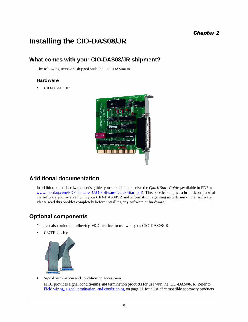
Hardware
CIO-DAS08/JR
Additional documentation
In addition to this hardware user's guide, you should also receive the Quick Start Guide (available in PDF at
www.mccdaq.com/PDFmanuals/DAQ-Software-Quick-Start.pdf). This booklet supplies a brief description of
the software you received with your CIO-DAS08/JR and information regarding installation of that software.
Please read this booklet completely before installing any software or hardware.
Optional components
You can also order the following MCC product to use with your CIO-DAS08/JR.
C37FF-x cable
Signal termination and conditioning accessories
MCC provides signal conditioning and termination products for use with the CIO-DAS08/JR. Refer to
Field wiring, signal termination, and conditioning on page 11 for a list of compatible accessory products.
CIO-DAS08/JR User's Guide Installing the CIO-DAS08/JR
9
Unpacking the CIO-DAS08/JR
As with any electronic device, you should take care while handling to avoid damage from static
electricity. Before removing the CIO-DAS08/JR from its packaging, ground yourself using a wrist strap or by
simply touching the computer chassis or other grounded object to eliminate any stored static charge.
If any components are missing or damaged, notify Measurement Computing Corporation immediately by
phone, fax, or e-mail:
Phone: 508-946-5100 and follow the instructions for reaching Tech Support.
Fax: 508-946-9500 to the attention of Tech Support
Email: [email protected]
Installing the software
Refer to the Quick Start Guide for instructions on installing the software on the Measurement Computing Data
Acquisition Software CD. This booklet is available in PDF at www.mccdaq.com/PDFmanuals/DAQ-Software-
Quick-Start.pdf.
Configuring the CIO-DAS08/JR
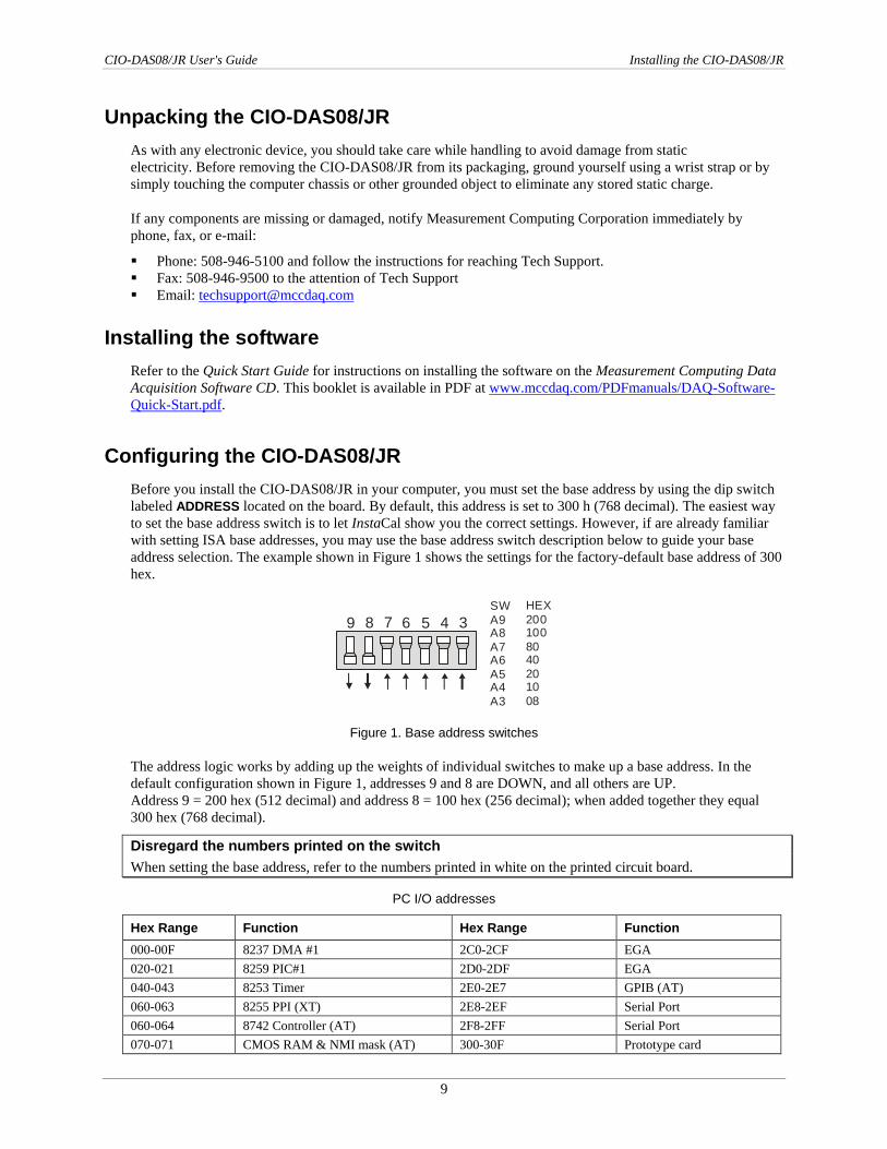
Before you install the CIO-DAS08/JR in your computer, you must set the base address by using the dip switch
labeled ADDRESS located on the board. By default, this address is set to 300 h (768 decimal). The easiest way
to set the base address switch is to let InstaCal show you the correct settings. However, if are already familiar
with setting ISA base addresses, you may use the base address switch description below to guide your base
address selection. The example shown in Figure 1 shows the settings for the factory-default base address of 300
hex.
5 4 369 8 7SW
A9A8
A7A6
A5A4
A3
HEX
200100
8040
2010
08
Figure 1. Base address switches
The address logic works by adding up the weights of individual switches to make up a base address. In the
default configuration shown in Figure 1, addresses 9 and 8 are DOWN, and all others are UP.
Address 9 = 200 hex (512 decimal) and address 8 = 100 hex (256 decimal); when added together they equal
300 hex (768 decimal).
Disregard the numbers printed on the switch
When setting the base address, refer to the numbers printed in white on the printed circuit board.
PC I/O addresses
Hex Range Function Hex Range Function
000-00F 8237 DMA #1 2C0-2CF EGA
020-021 8259 PIC#1 2D0-2DF EGA
040-043 8253 Timer 2E0-2E7 GPIB (AT)
060-063 8255 PPI (XT) 2E8-2EF Serial Port
060-064 8742 Controller (AT) 2F8-2FF Serial Port
070-071 CMOS RAM & NMI mask (AT) 300-30F Prototype card
CIO-DAS08/JR User's Guide Installing the CIO-DAS08/JR
10
Hex Range Function Hex Range Function
080-08F DMA page registers 310-31F Prototype card
0A0-0A1 8259 PIC #2 (AT) 320-32F Hard disk (XT)
0A0-0AF NMI mask (XT) 378-37F Parallel printer
0C0-0DF 8237 #2 (AT) 380-38F SDLC
0F0-0FF 80287 numeric CO-P (AT) 3A0-3AF SDLC
1F0-1FF Hard disk (AT) 3B0-3BB MDA
200-20F Game control 3BC-3BB Parallel printer
210-21F Expansion unit (XT) 3C0-3CF EGA
238-23B Bus mouse 3D0-3DF CGA
23C-23F ALT bus mouse 3E8-3EF Serial port
270-27F Parallel printer 3F0-3F7 Floppy disk
2B0-2BF EGA 3F8-3FF Serial port
Installing the CIO-DAS08/JR
After you configure the board's switches and jumpers, you can install the CIO-DAS08/JR into your computer.
To install your board, follow the steps below.
Install the MCC DAQ software before you install your board
The driver needed to run your board is installed with the MCC DAQ software. Therefore, you need to install
the MCC DAQ software before you install your board. Refer to the Quick Start Guide for instructions on
installing the software.
1. Turn your computer off, open it up, and insert your board into an available ISA slot.
2. Close your computer and turn it on.
3. To test your installation and configure your board, run the InstaCal utility you installed in the previous
section. Refer to the Quick Start Guide that came with your board www.mccdaq.com/PDFmanuals/DAQ-
Software-Quick-Start.pdf for information on how to initially set up and load InstaCal.
Connecting the board for I/O operations
Connectors, cables – main I/O connector
The table below lists the board connector, applicable cables, and compatible accessory products.
Board connector, cables, and accessory equipment
Connector type 37-pin D type connector
Compatible cable C37FF-x
DFCON-37 (mating connector)
Compatible accessory products with
the C37FF-x cable
CIO-MINI37
CIO-LAB8-TERM
Information on signal connections
General information regarding signal connection and configuration is available in the Guide to Signal
Connections (available at www.mccdaq.com/signals/signals.pdf).
CIO-DAS08/JR User's Guide Installing the CIO-DAS08/JR
11
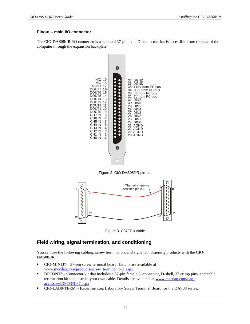
Pinout – main I/O connector
The CIO-DAS08/JR I/O connector is a standard 37-pin male D connector that is accessible from the rear of the
computer through the expansion backplate.
37 DGND36 DGND35 +12V from PC bus34 -12V from PC bus33 5V from PC bus32 5V from PC bus31 D 730 D 629 DIN528 DIN427 DIN326 DIN225 DIN124 DIN023 AGND22 AGND21 AGND20 AGND
ININ
N/C 19N/C 18
AGND 17DOUT7 16DOUT6 15
5 144 133 122 111 10
0 9CH7 IN 8
7 6 5 4 3 2
1
DOUTDOUTDOUTDOUTDOUTDOUT
CH6 INCH5 INCH4 INCH3 INCH2 INCH1 INCH0 IN
Figure 2. CIO-DAS08/JR pin-out
20
1
37
19
201
37
19
The red stripe identifies pin # 1
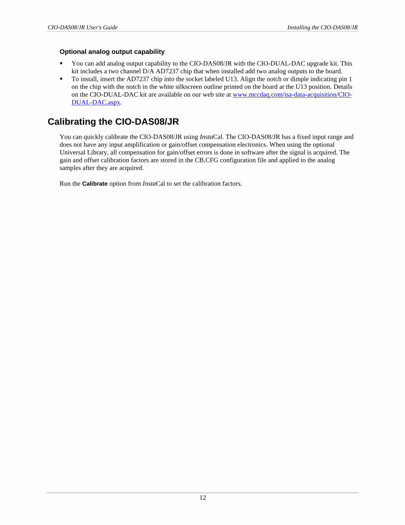
Female connector Female connectorFigure 3. C37FF-x cable
Field wiring, signal termination, and conditioning
You can use the following cabling, screw termination, and signal conditioning products with the CIO-
DAS08/JR.
CIO-MINI37 – 37-pin screw terminal board. Details are available at
www.mccdaq.com/products/screw_terminal_bnc.aspx
DFCON37 – Connector kit that includes a 37-pin female D-connector, D-shell, 37 crimp pins, and cable
termination kit to construct your own cable. Details are available at www.mccdaq.com/daq-
accessory/DFCON-37.aspx
CIO-LAB8-TERM – Experimentors Laboratory Screw Terminal Board for the DAS08 series.
CIO-DAS08/JR User's Guide Installing the CIO-DAS08/JR
12
Optional analog output capability
You can add analog output capability to the CIO-DAS08/JR with the CIO-DUAL-DAC upgrade kit. This
kit includes a two channel D/A AD7237 chip that when installed add two analog outputs to the board.
To install, insert the AD7237 chip into the socket labeled U13. Align the notch or dimple indicating pin 1
on the chip with the notch in the white silkscreen outline printed on the board at the U13 position. Details
on the CIO-DUAL-DAC kit are available on our web site at www.mccdaq.com/isa-data-acquisition/CIO-
DUAL-DAC.aspx.
Calibrating the CIO-DAS08/JR
You can quickly calibrate the CIO-DAS08/JR using InstaCal. The CIO-DAS08/JR has a fixed input range and
does not have any input amplification or gain/offset compensation electronics. When using the optional
Universal Library, all compensation for gain/offset errors is done in software after the signal is acquired. The
gain and offset calibration factors are stored in the CB.CFG configuration file and applied to the analog
samples after they are acquired.
Run the Calibrate option from InstaCal to set the calibration factors.
13
Chapter 3
Specifications
Typical for 25°C unless otherwise specified.
Specifications in italic text are guaranteed by design.
Analog input
Table 1. Analog input specifications
Parameter Specification
A/D converter type AD574
Resolution 12 bits
Number of channels 8 single-ended
Input ranges ±5 V
A/D pacing Software polled
Data transfer Software polled
A/D conversion time 25 µs
Throughput System dependant
Gain drift (A/D specs) ±50 ppm/°C
Zero drift (A/D specs) ±10 ppm/°C
Absolute maximum input voltage ±30 V continuous
Noise Distribution (Rate = N/A, Average % +/- 2 bins, Average % +/- 1 bin, Average # bins)
Bipolar (5 V) 100% / 100% / 3 bins
Digital input/output
Table 2. Digital I/O specifications
Digital type Output 74LS273
Input 74LS244
Configuration 8 fixed input, 8 fixed output
Number of channels 8
Output high 2.7 volts min @ -0.4 mA
Output low 0.5 volts max @ 8 mA
Input high 2.0 volts min, 7 volts absolute max
Input low 0.8 volts max, -0.5 volts absolute min
Power consumption
Table 3. Power consumption specifications
+5V 200 mA typical, 240 A max
+12V 17 mA typical, 22 mA max
-12V 28 mA typical, 36 mA max
CIO-DAS08/JR User's Guide Specifications
14
Environmental
Table 4. Environmental specifications
Operating temperature range 0 to 50°C
Storage temperature range -20 to 70°C
Humidity 0 to 90% non-condensing
Main connector and pin out
Table 5. Main connector specifications
Connector type 37-pin D type connector
Compatible cable C37FF-x
DFCON-37 (mating connector kit)
Compatible accessory products with the
C37FF-x cable
CIO-MINI37
CIO-LAB8-TERM
Table 6. Connector pin out
Pin Signal Name Pin Signal Name
1 CH0 IN 20 AGND
2 CH1 IN 21 AGND
3 CH2 IN 22 AGND
4 CH3 IN 23 AGND
5 CH4 IN 24 DIN0
6 CH5 IN 25 DIN1
7 CH6 IN 26 DIN2
8 CH7 IN 27 DIN3
9 DOUT0 28 DIN4
10 DOUT1 29 DIN5
11 DOUT2 30 DIN6
12 DOUT3 31 DIN7
13 DOUT4 32 5V from PC bus
14 DOUT5 33 5V from PC bus
15 DOUT6 34 -12V from PC bus
16 DOUT7 35 +12V from PC bus
17 AGND 36 DGND
18 N/C 37 DGND
19 N/C
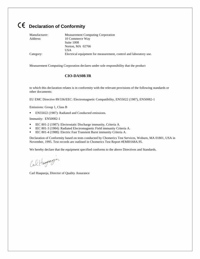
Declaration of Conformity
Manufacturer: Measurement Computing Corporation
Address: 10 Commerce Way
Suite 1008
Norton, MA 02766
USA
Category: Electrical equipment for measurement, control and laboratory use.
Measurement Computing Corporation declares under sole responsibility that the product
CIO-DAS08/JR
to which this declaration relates is in conformity with the relevant provisions of the following standards or
other documents:
EU EMC Directive 89/336/EEC: Electromagnetic Compatibility, EN55022 (1987), EN50082-1
Emissions: Group 1, Class B
EN55022 (1987): Radiated and Conducted emissions.
Immunity: EN50082-1
IEC 801-2 (1987): Electrostatic Discharge immunity, Criteria A. IEC 801-3 (1984): Radiated Electromagnetic Field immunity Criteria A. IEC 801-4 (1988): Electric Fast Transient Burst immunity Criteria A.
Declaration of Conformity based on tests conducted by Chomerics Test Services, Woburn, MA 01801, USA in
November, 1995. Test records are outlined in Chomerics Test Report #EMI0168A.95.
We hereby declare that the equipment specified conforms to the above Directives and Standards.
Carl Haapaoja, Director of Quality Assurance

Measurement Computing Corporation
10 Commerce Way
Suite 1008
Norton, Massachusetts 02766
(508) 946-5100
Fax: (508) 946-9500
E-mail: [email protected]
www.mccdaq.com