Embed Size (px)
Citation preview

" *c: 4*
DOCUMENT R!SIfl
'ID 193 070 SE 032 976
ADTHOR Erley, Duncan: Jaffe, MartinTIZLB Site Planning for Solar Access: A Guidebook for
Residential Developers and Site Planners.INSTITOTION American Planning Association, Chicago, Ill.WOOS AGENCY Department of Energy, Washington, D.C.: Department of
Housing and Orban Development, Washington, D.C.Office of Policy Development and Research.
EFFORT NC BOD-PtR-481ROB DATE Sep 79CONTRACT B-2573NOTE 146p.AVAILABLE FPCM superintendent of tocuments, D.S. Government Printing
Office, Washington, DC 20402 (Stock No.023-000-00545-Cr $4.75).
EBBS PRICE 0,01/PC06 Plus Postage.DESCRIPTORS *Civil Engineering: Construction (Process): *Energy:
*Sousing: Landscaping: Resource Materials: SiteAnalysis: *Site Development: *Solar Radiation:Technical Education
ABSTRACTThis manual is intended to guide developers, site
planners, and builders in designing residential developments so thataccess to sunlight is maintained for planned or potential solarcollectors. Almost any housing development can be designed tofacilitate the use of solar energy. Differences are not in costs butin planning. tescribed in this guidebook are the major elements ofplanning a housing site to protect solar access. These developmentsare: (1) site selection and analysis, (2) preliminary site planning,(3) general design approaches and techniques, (4) specific designstrategies, (5) landscaping and plantings. and (6) covenants andeasements. Also presented are two case studies shich desonstrateItheapplication cf approaches and techniques discussed. Over 100 figuresand tables supplement the written material. (NB)
************************************************************************ Reproductiods supplied by IMPS are the best that can be made ** from the original document. ****************************************s*******************************

Y
M.-
Site PlanningFor Solar Access:A Guidebook forResidential Developersand Site Planners
American Planning Association1313 East Sixtieth StreetChicago, Illinois 60637
Duncan Er leyMartin Jaffewith the assistance ofLiving SYsteras%Miters, California
Illustrations by Dava Lurie. , .
September 1979HUDMR-491
Contract Number: H2573

The research and studies forming the basis of thisreport were conducted pursuant to a contract withthe U.S. Department of Housing and Urban De-velopment (HUD), Solar Energy ,Program, part ofthe National Solar Heating and Coding of Build-ings Program managed by the U.S. Department ofEnergy (DOE). The statements and conclusionscontained herein are those of the contractor anddo not necessarily reflect the views of the U.S.Government in general or HUD or DOE in particu-lar. Neither the United States nor HUD nor DOEmakes any warranty, expressed or implied, or as-sumes responsibility far the accuracy or com-pleteness of the information herein.
This guidebook is one of a three-part series ofmanuals on solar energy and solar access pre-«pared by the American Planning Association forthe U.S. Department of Housing and Urban De-velopment The APA is a consolidation of theAmerican Institute of Planners and the AmericanSociety of Planning Officials.
The other two guidebooks in the series are:
Protecting Solar Access for Residential De-velopment: A Guidebook for Planning Officials,by the APA.
Solar Design Review: A Manual on ArchitecturalControls and Solar Energy Use, to be completedby the APA.
4

W,-
Acknowledgments
The authors wish to express their appreciationfor the assistance given by many individuals inwriting this report. We would particularly like tothank Charles Thurow of ARA for his guidance insupervising the project. William Thomas of theAmerican Bar Foundation also wrote large sec-tions of the chapter on private agreements and inaddition provided much assistance, support, andlegal advice. Robert Cassidy of Chicago, Illinois,edited and revised sections of the report in addi-tion to making valuable suggestions about r-ganization and presentation. natty, the staff ofLiving Systems, including Jon Hammond, JamesZanetto, lento Evans, and Bruce Maeda produceda good portion of the technical data in the book.The APA secretarial staff worked long hours toproduce numerous drafts.
On two separate occasions after preliminarydrafts were completed, a group of twelve came toChicago to review the drafts. The review sessionparticipants were: Christopher M. Blanton of Sto-tar, Heitunann and Eder, St. Louis, Missouri; Gil-bert Finns', Jr., School of Law, University ofHouston, Texas; Gail Hayes, Environmental LawInstitute, Washington, D.C.; Tudor Ingersoll,MassOesign, Cambridge, Massachusetts; LaneKendig, Lake County Regional Planning Com-mission, Waukegan, Illinois; William Northrup,Indio Planning Office, Indio, California; and LarryReich, City of Baltimore, Department of Planning,Baltimore, Maryland. In addition, members of thedevelopment community also offered their com-ments, suggestions, and criticism on earlierdrafts, to assist us in writing a better report. Wewish to thank Jay H. Feldman, Assistant Directorof the National Housing Center of the NationalAssociation of Home Builders, Washington, D.C.;Ralph J. Johnson, President of the NAHB Re-search Foundation, Incorporated, Washington,D.C.; Durwin Ursery, Urban Investment, Incorpo-rated, Chicago, Illinois; and Dick Wirth, BuildingIndustry Association of Southern California, LosAngeles, California.
Finally, we wish to acknowledge the HUD SolarEnergy Program, especially David Engel, whoserved as project officer on this project but wentbeyond that status by giving us suggestions andthe time to make the report what we thought itshould be. He was a valuable resource as wellas an understanding government representative.
5 5
cM
A
Malmo lodgments
This report was prepared by the staff of theAmerican Planning Association. The APA Spon-sored Research Program is an independent re-search activity supported by grants and devotedto advancing public agency planning practice. In-dividual reports are not reviewed for approval bythe Board of Directors or by the membership ofthe Association. Israel Stollman, ExecutiveDirector, David R. Mosena, Director of Research.
6
6
1

Table of Contents
Introduction 11
Site Selection and AnalysisThe Suns Poskion in the SkyLatitude and TopographyAenospheric ConditionsAssessing Shading by Natural and Man-Made ObjectsAssessing Existing Shading on a SiteAssessing Enemy ConserySite Assessment Criteria
ation
Preliminary SiteSolar Acces.
RenninConsidering s ObjectivesAssessing Lund ReguiadonsSte Planning Criteria and ProceduresSite Analysis CheddistA Solar Site Planning Example
General Denton Approaches and ischniques for Solar AccessThe Reiadonship of Building and Site DesignBuilding Orientation and Solar AccessTechniques for Analyzing Solar Access
Spoons Design Strategies to Protect Solar AccessLaying Out RoadsLot Design StrategiesSiting Strategies for Single Family Detached HousingSiting Strategies for Low-Rise Multifamily HousingSiting Strategies for High-Rise HousingPlanning Open Space
Ives and LandscapingSolar Access and Existing VegetationNew Vegetation: Project LandscapingMaintaining Vegetation: Pruning and ThinningGuidelines for PlantingsRegional Vegetation Guidelines
Avo Examples of Solar Sits PlanningDetermining Planning CriteriaSite Select:onSite Analysis and Preliminary Site PlanClimateVegetation and Site CharacteristicsConventional DevelopmentPlanned Unit Development
Private Agreements to Protect Solar Access: Covenants and EasementsRestrictive CovenantsEasements
12
31
47
69
91
105
117
7 7
4.

List
ofF
igures
and
Titles
Appendix
I: Glossary
Appendix
N:
Skyspace
Angles
Appendix
IN:
Shadow
Length
UM
*
and
Equation
Appendix
IV:
Determ
ining
Density
Appendix
V:
References
123129
132140
148
List
of Figures
and
Tables
Figure
Page1 F
lash
NW
Analogy
to Solar
Radiation
142 Latitudes
of the
Contiguous
48 States
143 The
intensity
of Sunlight
Decreases
with
Latitude
and
Season
Because
of the
Tilt
of the
Earth4 A
zimuth
and
Altitude5 W
inter
and
Sim
mer
Sun
Paths6 T
he
Sun
is Lower
in the
Sky
and
the
Shadow
s
Longer
in Winter7 R
adiation
and
Shadow
Length
on a South
Slope8 B
ulking
Overheating9 S
hadow
Length
of 10Foot
Tall
Object
and
Radiation
Table
for
417
North
Latitude
at
Winter
Solstice10 A
bsorption
by the
Atm
osphere11 Orientation
in Fog-P
rone
Area
12 Inversions
as
Solar
Access
Constraints13 C
ollector
Efficiency
loss
by Shading14
Winter
and
Sum
mer
Shadow
Patterns15 D
etached
Collectors
Can
Be
Used
Where
There
is Excessive
Shading16 S
hading
byT
opography17 Vegetation
Can
Buffer
Against
Cold
Winter
Winds18 R
egional
Clim
ate
Zone
Map19 Levels
of Solar
Access20 A
ir
Solar
Altitude
is Necessary
to Define
Solar
Skyspace
for
Active
Collectors21 S
olar
Skyspace
Plan
View
22 Solar
Skyspace
(Plan
)P
lan
and
Isometric
View
s)23 Recom
mended
Skyspace
Angles
for
Decem
ber
21
24 Skyspace
Boundaries
for
Water
and
Space
Heating25
Skyspace
and
Solar
Energy
Use
Table26 S
kyspace
Begins
atthe
Roof
Eaves
for
Rooftop
Access27 T
opography
and
Skyspace28 S
hadow
Lengths
Are
Shorter
and
Higher
Densities
Easier
on
South
Slopes29 W
ind
Buffers
Can
Reduce
Collector
Area
30 Base
Maps
Should
Be
Analyzed
forbSolar
Access31 S
ite
Exclusions
Marked
on
the
Base
Map
32
Areas
ofP
oor
Solar
Access
Should
Be
Marked
on
the
Base
Map33 A
reas
with
Poor
Energy-C
onservation
Features34 Land
Use
as
Allocated
on
the
Site
35 Building
Design
Can
Assist
Solar
Access
36 Reducing
Building
Height
to Improve
Solar
Access 8
a

/11.411.41MM
E19503131365IR
RIfIl
2

.4*
1

..,........

..,........

, N.,4,0-1, .1,1V
,sk"
'CV

Because the earth is tilted on its axis, the al-titude of the sun at a given location depends onthree factors: the time of day, the latitude. andthe season.
Common sense shows that the sun's Nght ismost intense at solar noon, when it reaches itshigh point-In the sky for the day. and it is weakestat sundial and sunset. when it is lilted away fromthe silt's position on the earth's surface. Thesecond factor. latitude. or the distance north orsouth of the earth's equator, also affects thesun's position in the sky. Because of the earth'scurvature, the farther north one goes in thenorthern hemisphere, the lower the sun appearsto be in the sky and the less its intensity. Finallythe change of seasons also affects the Intensityof sunlight, particularly in latitudes distant fromthe equator. if the earth's axis were perpendicularto the plane of the earth's obit around the sun,there would be no change of season. Since theearth's axis Is tilted at about 23.5 degrees fromthe perpendicular, the northern hemisphere istilted slightly toward the sun in summer andslightly away from it in winter. (The situation is
Site Selection and Analysis
reversed, of course, for the southern hemi-sphere.) Because the sun's rays are more nearlyperpendicular to the site in summer than inwinter, it is hotter in summer than in winter.
Although the sun's position in the sky changesfrom minute to minute, season to season, andlatitude to latitude, its position at any one timecan be determined by using two measurements,altitude and azimuth. Attitude is the distance,measured in degrees, between the sun and thehorizon-0' at sunrise and sunset, to a maximumof 90'. Azimuth is the distance, measured in de-grees, of the sun relative to due south. It is ex-pressed es a negative value to the east and as apositive
fvalue to the west.
360(It can also be mea-
sured rom the north, using degrees, but thatmethod is not used here.) The sun's azimuth isgreater in the summer than in winter because thesun rises and sets farther north in summer. Fig-ure 4 shows how altitude and azimuth are mea-sured. Figure 5 shows the path of the sun at 40°north latitude during the solsticesthat is, thedays when the longest (summer) and shortest(winter) periods of sunlight occur.
15


Site Selection and Analysis
I 7' 17

Site Selection and Analysis
Recalling the flashlight analogy, it is now dearthat the sun is less intense in the morning and af-ternoon hours because it is at an oblique angle tothe earth's surface. This phenomenon also ac-counts for the lesser amount of solar radiationavailable in winter, when the earth's tilt lowers theapparent position of the sun in the sky. *Finally, itexplains why less solar radiation is available athigher latitudes. Because of the earth's curvedsurface, the sun appears lower in the sky andsolar radiation is more oblique to the earth's sur-face. Thus, the sun's daily and seasonal positionis crucial to site selection because areas perpen-dicular to the sun's rays receive more solarenergy than areas oblique to sunlight.
Having reviewed these facts, it is now possibleto turn to the methods for assessing the availabil-ity of sunlight on a given site.
Latitude and TopographyThe latitude and topography of a site affects boththe availability of sunlight and the length of
shadows cast by objects on the site. At higherlatitudes, the sun is lower in the sky; creatinglonger shadows. Likewise, changes in topog-raphy affect the angle at which the sun hits theground. On south slopes, as at lower latitudes,sunlight is more nearly perpendicular, soshadows are shorter than on flat land or on anorth-facing slope. More solar radiation is alsoavailable on south-facing sites, as figure 7illustrates.
In the northern hemisphere, south slopes areoptimum for solar energy use. Because the sunIs in the southern sky, south slopes are mostnearly perpendicular to the sun's rays, and there-fore can capture a greater amount of winter solarradiation than other slopes can.
The greater amount of solar radiation and theshorter shadow lengths make it easier to plan forsolar access protection on these slopeithan onmany other areas of the site. Because of theshorter shadow lengths, buildings can be sitedcloser to one another without obstructing solaraccess, and higher densities may be possible.
Figure 7. Radiation and Shadow Length on a South Slope
A
Area of ground receiving the ray on flatground (B) is larger than area on southslope (A). Thus more energy is receivedper unit area on the slope.
Shadow cast by tree on flat ground (B) islonger than the one cast by same tree onsouth slope (A).
18

Because south slopes absorb more winter solarradiation, they tend to be warmer than otherplaces on a site and therefore have more moder-ate temperatures in cooler climates during thewinter. With winter temperatures moderated, lessenergy (whether solar or conventional) is neededto maintain comfortable temperatures in struc-tures located in these areas.
Other slopes are less ideal for solar accessand solar energy use. East and west slopes getmore sunUght in summer and less in winter thansouth slopes. The sun rises far to the north insummer, striking east and west slopes almostperpendicularly. This can cause overheating ofbuildings in summer, particularly if the structureshave large window areas on the west and eastwalls. Overheating is a particular problem in thelate afternoon, when the west side of a building isexposed to afternoon sun. If a building isadequately shaded in summer, however, eastand west slopes can still be suitable for solardevelopment.
Sta Selection and Analysis
North slopes are the least ideal for solar ac-cess and solar energy use. Shadow lengths areextremely long, making site planning difficult ifsolar access is to be preserved. The obliquesolar angles mean that the slope tends to be colderin the winter months. In those climates with pre-dominant north winter winds, these slopes arealso more-exposed, and buildings are more apt tolose heat than those in sheltered locations.
Energy availability and shadow length alsovary with slope gradient. The steepness of aslope accentuates the conditions created byslope direction. In other words, if south slopesare warmer than other slopes and have shortershadows, then steeper south slopes will bewarmer still - and have even shorter shadows.Similarly, if north slopes are cooler, they will beeven colder if slope gradient increases. Figure 9shows a comparison of all four slope drectionson radiation gain and shadow length for an object10 units tall on a hypothetical site with two differ-ent gradients.
<=E
Figure 8. Building Overheating
.The afternoon sun can cause overheating in houseswith large west-facing windows.
Wes`
119

Site Selection IMO Analysis
Figure 9. Shadow Length c4 10Foot 1911Object and Radiation ibblefor 40' North Latitude at Whiter Solstice
North Face South Face East Face West FaceHorizontal
Radiation/Day 675 BTU 675 BTU 875 BTU 675 BTUShadow Length 20 ft. 20 ft 20 ft. 20 ft
10 Percent SlopeRadiation/Day 445 BTU 897 BTU 688 BTU 666 BTUShadow Length 302 ft. 14.8 ft 20 ft 20 ft
20 Percent SlopeRadiation/Day 224 BTU 1101 BTU 637 BTU 837 BTUShadow Length 73.7 ft. 11.6 ft 20 ft 20 ft.
Solar access planning and site analysis onsteeper slopes are constrained the same as forconventional development. The steeper theslopes, the more sophisticated and expensivemust site preparation be. The development ofmoderate south slopes Is a good idea for bothsolar access and conventional developments.
Atmospheric ConditionsThe atmosphere can also affect the availability ofsunlight. For one thing, the atmosphere has a fil-tering effect on sunlight The more atmosphere agiven beam of sunlight has to penetrate, the lessits intensitst That is another reason why the sunis less intense in the morning and afternoon. Itsrays have to cut through a thick slice of theearth's atmosphere, where they can be absorbedby clouds, pollution, and the atmospheric gasesthemselves. The greater the distance sunlightmust travel through the earth's atmosphere, themore It will be absorbed, and the less intense itwill be.
Specific stmospheric conditions also take the:-toil of sunlight. Fog, in particular, is one condition
20
that should be assessed. Because fog caused bycold air concentrations can significantly limit solaraccess, sites within a few hundred feet of eachother may have very different solar potentials.This is especially true in the Pacific Fog Belt.(See figure 18.)
In areas of occasional morning fogginess, thecollector can be pointed slightly west of due south,allowing the morning sun to bum off the fog andleaving the collector to gain solar radiation duringthe afternoon hours. (See figure 11.) In areas withsevere constraints, a great deal of care must betaken to avoid fog-prone areas.
The amount of solar radiation that reaches asite is partly dependent upon the clearness of theair. Cloudiness affects a site's solar potential byobstructing direct sunlight to solar collectors.Clouds also can limit natural cooling by inhibitingthe re-radiation of heat to the night sky. Finall% alrquality will affect a site's solar potential. In ruralareas, agricultural dust and dust clouds fromquarries or other industry can lessen the sun'spower. In urban areas, heavy industrial smoke,water vapor, and photochemical smog and dustcan have similar effects.
20

4"
Site Selection and Analysis
9 tti .4.
21

Site Selection and Analysis
Severe temperature inversions also can totallychange the solar access $ the basins surround:Jog major cities. An inversion is a layer of cold aircapped with a layer of warm air that inhibits verti-cal miidng of the atmosphere, trapping smog andhaze in the tower layer. (See figure 12.) Like fogs,inversions usually have sharp boundaries. Twosites, one above the inversion belt and one below,can have entirely different solar potentials.
Assessing Shading by Natural and Man-MadeObjects
A shadow cast on a solar collector affects a solarenergy system's energy production in two ways.First, of course -the- reduction of the amount ofsunlight collected diminishes the amount of lightthat can be converted to heat or other forms ofenergy. The second loss in energy efficiency re-sults from the radiation of heat from the shadedportion of the collector to the cooler surroundingair. Thus, it is crude' to site collectors so that theyare not shaded.
Because shadows affect solar collectors, it isnecessary to determine the shadow of an objectnear a collector. This is called the object's shadowpattern. Although a somewhat crude method, theshadow pattern enables the site planner to iden-tify potential locations' problems in siting a solarcollector.
A technique for drawing shadow patterns ispresented in the chapter on design approachesand in Appendix Ill. The developer or site plannershould study this technical material in order to un-derstand the techniques necessary for assessingshadows. At this point, however, a few generaliza-tions can be made concerning shadows and theireffects on solar access.
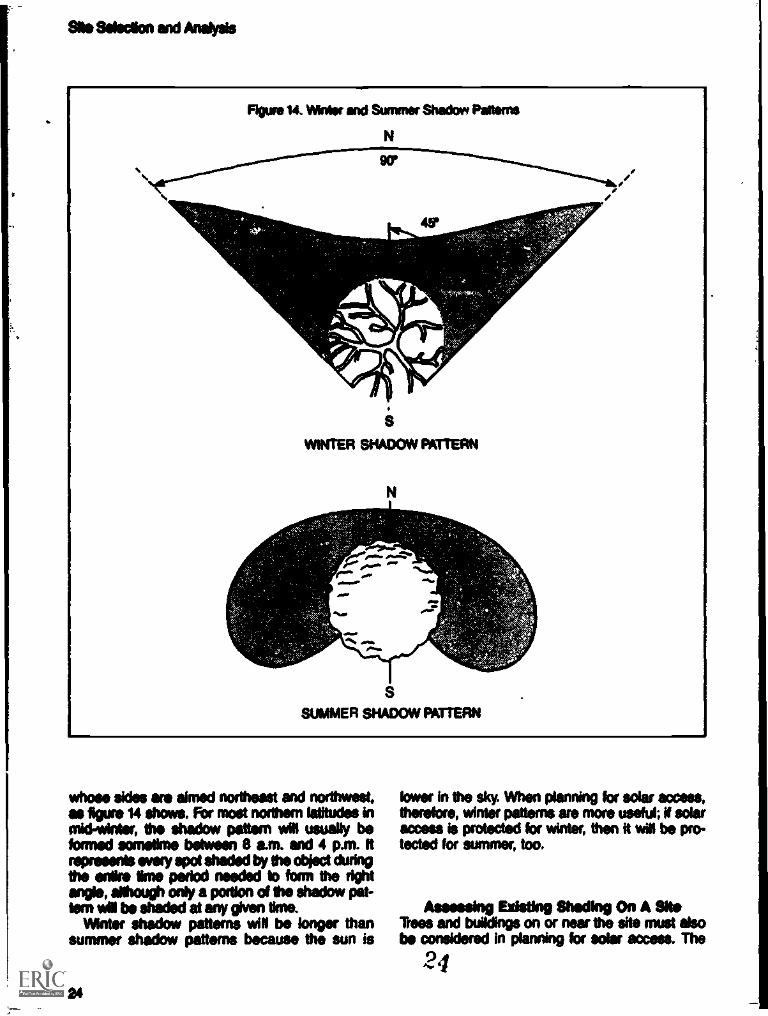
A shadow pattern is :he composite shape of ashadow cast by an object over a given period oftime. For the sake of convenience, the boundariesof the shadow pattern are defined by the sun'sazimuthtwo shadows, one falling 45 degreesnortheast and one falling 45 degrees northwest ofa north/south fine running through the center ofthe object. This, in effect, creates a right angle
Figure 12. Inversions as Solar Access Constraints
22 22

Site Sekodion and Analysis
Flour* O. COM°, Money Lois by Shodine
A SOLAR COLLECTOR GAINS HEAT FROM THE SUN AND LOSES HEAT TO THE AIR.
AN UNSHADED COLLECTOR GAINS MORE HEAT THAN IT LOSES
HEAT LOSS
SHADING PART OF A COLLECTOR REDUCES HEAT GAIN AND LOWERS THE AMOUNTOF USABLE HEAT THE SYSTEM CAN PRODUCE
23
.
1

Site Selection and Analysis
A,Figure is. Detached Collectors Can B. Used Whets Theo Is &NNW Shading
1111 ':47.:
shadow patterns for objects both on and to thesouth of the site are calculated (using thetechniques in Appendix 10), and houses are lo-cated out of their way. Remember that in summeror in hot dime's 'hiding is desirable and the b-callon of some tali trees or buildngs can be usedto the developer's advantege.
N tress or structures cast unwanted shadows,then the developer may have to consider alterna-tives, such as using detached collectors. If an off-site object casting the problem shadow is a tem-porary structure, abandoned, or otherwise out ofuse, the developer could consider negotiating withthe Miner for its removal.
When an adjacent site to the south is unde-veloped or only partly developed, the developermay wish to protect his site against shading byfuture development on this adjacent parcel. A pri-vate agreement between neighboing landowners,
possibly an Easement, may be an appropriateresponse. Then legal shategies are discussedin greater detail in the chapter on privateagreements.
Remember, too, that Ms and mountains cancause shading problems on a site. Developmentlocated close to the base of high or steep topo-graphical features may be shaded during large por-dons of the daf II a project is located just to theeast of a large hi, for wimple, Nis possible thatthe area may be shaded Weave* early in the af-ternoon. In order to locate the development *WOshading is least a problem, the developer or siteplanner should ohs& to see when the shadowsof topographic features fail at various times in etewinter. (See figure ie.) Cross-section of the sitecan be drawn and critical solar angles analyzed todetermine where and what shading is likely to bea problem.
25

ale Selection and Aft**
Figure ii. Shaft by %PON"
Asessetag ISM Conservadonin *NON to evaluating solar access, the siteplanner or dateloper met also consider the site%characteristics and their intents! sleds on over-all Emig use in future buildings. The misrodi-num of a site le an imported dstentinant of theamount d energy that will be needed to hest andcool the buildings. Some sites are warmer inwinter and cooler in summer than others. A site
1
that moderates temperature and climatic ex-tremes also moderates a building's heating and000lng needs, and oder collectors wait moreelliderily on such else.
Besides topography, other tutors should beconsidered. Mind wow can be aliacted by strategi-cs* located trees or stands d trees, which canbe used to block cold winds in winter and hotdusty winds in summer. lees can also channel
a 26
Site Selection and Analysis
cooling breezes to places where they are needed,significiantly lowering the heating or cooling load91 a building.
The presence of large bodies of water has amoderating effect on the mianclimate of a site.They also produce coding breezes in the sum-mer. dircago's Lake Michigan shore area iscooler in summer and wanner in winter than in-land areas. Mountains and hills can act aswindbreaks and are especially advantageouswhen they are located in the direction of prevailingwinter winds. (See reference to Olgyay andAmerican Society of Landscape Architects inAppendix V.)
NA Research Corporation. Regional Guidelines for BuildingPassive Energy Conserving Homes.
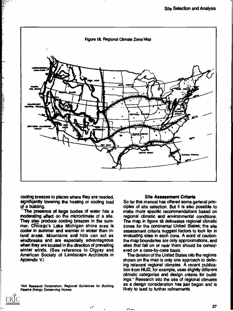
Site Assessment CriteriaSo far this manual has offered some general prin-ciples of site selection. But it is also possible tomake more specific recommendations based onregional climatic and environmental conditions.The map in figure 18 delineates regional climaticzones for the continental United States; the siteassessment criteria suggest factors to look for inevaluating sites in each zone. A word of caution:the map boundaries are only approximations, andsites that fall on or near them should be considered on a case-by-case basis.
The division of the United States into the regionsshown on the map is only one approach to defin-ing relevant regional climates. A recent publica-tion from HUD, for example, uses slightly differentclimatic categories and design criteria for build-ings.* Research into the use of regional climatesas a design consideration has just begun and islikely to lead to further refinements.
27

i 1
hi I il t
r I 1
I
I1Ii

Preliminary Site Planning
Considering Solar Access ObjectivesLein* of Solar AccessSolar SkyspaceTopography and Solar Skyspace
Assessing Local RegulationsBarriers in Regulations to the Use of
Solar EnergySolar Access, Density, and Environmental
ProtectionConventional Wows Planned Unit Development
Sits Planning Criteria and ProceduresPreliminary Site Planning Procedures
Site Analysis ChecklistA Solar Site Planning Example
Once a site has been examined for access to sun-light, shading problems, and energy-conservingfeatures, the developer or site planner can beginpreliminary site planning. This chapter discussespreliminary site planning as a three -step process:first, solar access goals are adopted; then, localregulations are assessed; finall% a base map ofthe site showing constraints and opportunities isdeveloped.
Considering Solar Access ObjectivesThe developer's first task in preliminary site plan-ning is to consider the optimum amount of solaraccess for the development. In protecting theavailability of sunlight to solar collectors, the de-veloper must consider where the solar collectorsmay be located and how much area around themmust be kept free of obstructions.
Levels of Soler AccessThe collector locations for active and passiveheating systems fall into four categories: rooftop,south wall, south lot, and detached. (See figure19.)
Rooftop access may be the best altemative forhigh-density developments or sites where topog-raphy or high northern latitudes make south-wallaccess difficult or impossible. This level of accessmay involve the least number of design considera-tions, especially if buildings in the developmentare all of the same height and not likely to shadeone another. For tete situations, site planningfocuses on possible shading from trees or tallbuildings in neighboring developments. Rooftopaccess may be most appropriate for solar hot waterheating and active space heating collectors.
3f) 31

*.11,0Preliminary Site Planning
South-well access is recommended for almostevery development situation, simply because itleaves open the possibility of using either active orpassive solar energy systems. South-wall accessis particularly appropriate where a developer ismerely subdividing and not necessarily bulking adevelopment. It preserves a variety of solar op-tions for future lot owners. South -wail access canalso be important when using roof-mounted col-lectors, because south glazing can assist thesolar energy system in space heating.
South-lot access is more difficult to achievethan either roof or south-wall access. It may re-quire greater care in the siting of buildings andtrees to minimize shading problems. Some cli-mates permit the use of a reflector to increasesunlight falling on a collector, and south-lot accessmay be necessary for the proper placement of thereflector. Where a light-colored or snow-coveredpatio is used as a reflector to increase radiation tothe collector, these features should be consideredby the site planner or developer. Similarly, the useof a solarium or solar greenhouse could requirethat south -lot access be considered a solar ac-cess objective. RIMY, south -lot access is alsodesirable in regions where residents make exten-sive use of yards and patios; south-lot access canprovide a warm, sheltered location for outdooractivities.
32
Detached collector access can be consideredin situations where rooftop mounting of collectorsis not possible or desirable. For example, in heav-ily wooded areas whe the vegetation must bepreserved, or in hot climates where maximumshade is desirable, detached active collectorsoffer a good compromise. Detached access maybe necessary for those sites with predeterminedplots and/or street layouts that have precludedgood solar access. In warmer climates, wherespace heating may not be necessary but wheresolar water heating is important, the house can beshaded by nearby trees or sunscreens to reducethe need for air conditioning, and a detached col-lector can be used. Detached collector arrayscanbe mounted in a variety of locations and can be in-tegrated with other site uses, such as open spaceor accessory buildings.
The developer or site planner may also wish toconsider the effects of solar access on the coolingneeds of new residential development-policy-tarty in those regions where most residentialenergy is used for air conditioning. Active solarcooling systems have virtually the same accessneeds as active solar heeling systems. High-temperature solar collectors require direct accessto sunlight in order to work properly. Passive ornatural cooling systems have fewer access re-quirements than passive heating systems. Clear

access to the cool sky or unobstructed access tocooling winds is all that is necessary. Maximumshading of buildings using passive cooling (to re-duce heat loads) is more important than solar ac-MS in hot climates.
In most cases, a developer need only decidebetween active or passive solar energy systemsbefore being able to determine the necessarylevel of solar access. General% the more solaraccess provided, the greater the need for carefulsite planning considerations. As access changesfrom roof access to south-wall access to south-totaccess, the placement of trees and structures be-comes more crucial to prevent shading of theseareas.
Solar SkyspaceOnce a developer has determined the level ofsolar access for the project, the individual unit ofsolar access, called solar skyspace, must be con-sidered. Solar skyspace is that portion of the skywhich must remain unobstructed for a collector tooperate efficiently; in other words, the area to thesouth of the collector that must be kept free ofobstructions when the collector is in use. Solarskyspace for most solar heating systems is de-termined by the sun's position at the winter sol-
Preliminary Site Planning
stice (December 21), when solar altitude andazimuth angles are smallest and shadows arelargest
As a rule-of-thumb, 12 degrees altitude can beused as a cutoff point for solar skyspace. Roughly80 percent of the sun's energy is received whenthe sun is at or above 12 degrees altitude as illus-trated in figure 20. The sun is in this position be-tween 8 a.m. and 4 p.m. for most latitudes atmid-winter. This altitude corresponds to 45 to 50degrees azimuth either side of south, forming a 90or 100 degree wedge; a line bisecting this wedgewould point north/south. In most of the UnitedStates, below 45 degrees north latitude, 45 de-gree azimuths are used to define skyspace.These limits are expressed in azimuths becausedock time is often significantly different from solartime.
Thus, the eastern and western boundaries ofthe skyspace may be defined by 45-degreeazimuth angles. The altitude of the sun on De-comber 21 and June-21 determines the upper andlower boundaries of the skyspace in most cases.Figure 22 shows in two different views how thewinter and summer paths of the sun connect withthe east/west boundaries to define the skyspacearea.
The upper and lower skyspace boundaries alsodepend on the type of system to be used. For in-
Figure 20. A 1?Solar Altitude is Necessary to Define Solar Skyspace for Active Collectors
3;1 33

PrilfritrifirY Site Planning
Figure 21. Solar Slop-pace (Plan View)
A
45° swespAcE 45° \
N
45°
/ \/ 4"---& \/ 45° \w--SKYSPACt....../ \
DUE SOUTHBEARING
WINTERSUNPATH
Figure 22. Solar Skyspace (Plan and Isometric Views)
SUMMERSUNPATH
wIrSKYSPACE
4r 45°
SUMMERSUNPATH
WINTERSUNPATH
312M
34 'j

Preliminary Site Planning
Figure 23. Recommended Skyspace Angles for December 21
N. LatitudeAM/PM Position*
Azimuth Altitude
45° 25°
Noon Altitude
42°
Percentpayiation
78%
317 45° 37° 80%
a5° 45° 16' 32° 85%
40' 45° 12° 27° 90%450** 001 (12') 88%
48°" (50') (12') ir 87%
The AM/PM angles presented in this chart are the same for both east of south and west of south. Forexample, if the skyspace azimuth is 50', then the protected area goes from 50" east of south to 50°west of south.
"The 50' azimuths are not based on December 21st, but are suggested as a compromise to assuresolar access during the entire heating season exclusive of the winter solstice period. Similarly, the 12degree altitudes apply only to those months when the suns path is 12 degrees above the horizonMalin the 50 degree azimuth angles. See Appendix IL
***Radiation is based on the percentage of total available radiation falling on a horizontal surface onDecember Z. Example: If the skyspace between 45° east of south and 45' west of south isprotected at 30' latitude, then 80% of the available radiation will strike the collector. If the collector istilted, then these percentages may be even highet
stance, a hot water system needs year-round ac-cess, so the lowest winter sun angle and highestsummer sun angle are used in defining skyspace.A space heating system used only in winter canoperate efficiently with a lower skyspace bound-ary. (See figure 24.)
In either case, me upper boundary is not as im-portant as the lower The lower boundary is formedby the sun's path at its lowest point; on Decembei21 the problem with shadows will be most difficult,because that is when the shadows are longest.Only for passive cooling systems, which radiateheat to the cool night sky and need an open spacedirectly overhead in the summer, is this considera-tion irreelevant.
In summary solar skyspace for heating pur-Pons is defined by the path of the sun on Do-
comber 21 between 45 degrees east and west ofsouth. In planning a development, large objectscapable of casting significant shadows should belocated so that they do not intrude into the sky -space wedge or extend above the lower boundary.Figure 25 shows three solar energy uses and de-scribes how the season during which each is usedaffects solar skyspace. (Skyspace is discussedfurther in Appendix I.)
By combining the level of solar access with thesolar skyspace, the developer can determineexactly what area must be kept free of obstruc-tions. If rooftop access is the goal, for example,the individual skyspace unit begins at the buildingeaves (as figure 26 shows); if south-wall access ischosen, then the skyspace begins at the bottom ofthe south wall.
.74/ 35
.1

Mil Winery Site Planning
CrN
Figure 24. Skyspaoe Boundaries for Water and Space Heating
JUNE 21
MARCH/SEPTEMBER 21.1
../ tDECEMBER 21./ e. // .. -
/ ,/,. ...
.// e//. ,, ...
......."
...".....
WATER HEATINGREQUIRED YEAR-ROUND
MARCH/SEPTEMBER 21
SPACE HEATING REQUIREDFROM SEPTEMBER/MARCH
536


Pf01111411ary Site Planning
Topogrephy and solar SkyspeceChanges in topography do not change solarskyspace. An unobstructed area is necessary ona slope facing any direction. What does change isthe distance between the ground and the loweredge of the skyspace. A south slope automatically"aims" its collector higher, so neighboring objectscan be tall without casting shadows on it. A coNector on a north elope will be aimed toward the crestof a hill, so even very short objects may castshadow onto the collector. Figure 27 illustratesthis point.
Slopes can affect the developer's designstrategies. On a south slope, for example, it ispossible to put in higher densities of housing withunobstructed solar access than on north slopes.Similarly, solar access may be limited on steepnorerslopes unless density or layout is changedto account for the lower solar *Vac* over WO'cent lots.
Assessing Local RegulationsLanduse controls establish developmentobjectivesthe density, the number and kinds ofstructures allowed within the development, therequirements for kdrasthrcture (such as sewers,electric Ines, and water), and for public amenities(such open space). lb be approved y thecommunity a development proposal must
bmeet
these standards.But it may be unclear to what extent local regu-
lations oiler opportunities or bonitos to develop-ments planned for solar access. Actual* it de-pends largely on the type of development and thelanduse controls in effect in the community. Acommunity, for example, may have highly restric-tive zoning standards governing now develop-ment, standards that rule out solar equipment.Another, however, may have flindble developmentregulations, such as planned unit development(PUD) provisions that offer developers a great
Figure 21. Topography and SkYaPana
N
FLAT LAND
DISTANCE A IS GREATER THAN B. AND B IS GREATER THAN C.
39

1
1
.:.
'I
iiiiip
pim
plim
imill
, Tor
t1
i1;
jiiiii
iiii.
ii!Ir
. 1101
1161
Ii
aiiii
itV
iiti
fila
illiq
uilil
lI *
RID
Ilin
:14
i
1lit
tillip
ligel
liiii
iillil
lill
I11
1411
1W
W1
Mil
la I
lilt'
''I/
II11
111
1
0H
iligi
iinfl
itlit
Piti
tHili
ts.il
:i.
Ihni
-
51A
llitth
giggl
iiiri
hiPl
itilli
giiin
iII;
e.,)
Wie
lir.
tagg
iViM
1111
1/11
4111
1111
1ii
glig
h 1.
1111
4111
! III-
iiill
ii§IV
4ilt
Y 1
gal
th 0
ifiti
dilli
iiiiii
iitio
litilm
hilti
llOrd
q1:
htili
phho
rkiti
oilio
goll
ii11
1.61
.31
illI
Lih
illik
3 ilt
irdy
lhii
iv I
mill
Itim
ilii

II

Preliminary She Plannhig
less so than if the building were not solar tem-pered). The heat from a solar collector is towgrade when compared to the heat generated bya furnace. A solar collector is most efficient whenit is well integrated with the natural features ofthe site. (See figure 29.)
The most cost- and energy-efficient use ofsolar energy can be calculated by using certaincomputer models, such as HUD's RSVP (Resi-dential Solar Viability Program) or the Depart-ment of Energy's SOLCOST program. informa-tion about these programs is available from theNational Solar Heating and Cooling InformationCenter, which also offers guidance in choosingthe optimum collector size for a specific dwelling.The economics of solar use are beyond siteplanning. As in conventional environmental siteplanning, careful site planning merely shifts costs
._to an earlier stage in the development process.They are recouped in lower construction costsand do not increase total project costs.
42
Preliminary Site Planning ProceduresBased on the analysis of the site, the developeror site planner can proceed to allocate the majorland uses of the project, including housing, openspace, and transportation. in practice, siteanalysis and preliminary site planning are ac-complished more or less simultaneously but arepresented separately here for simpliffcation.
Assessing a site for solar access and energyconservation is only a part of preliminary siteplanning. Developers must also decide whichareas of a site are more desirable for buildingfrom an environmental standpoint. Some areas,for example, have more stable soils than others.The goal is to identify suitable areas for build-ings, open space, streets, and other componentsof the project.
In analyzing the site, solar access andenergy-conserving features of the site should beidentified and mapped on a base map. The basemap should be an aerial photograph of the site, a

Preliminary Site Planning
topographic map, or a land feature sketch. (Seefigure 30.) The site can then be evaluated ac-cording to the site analysis cheddist.
Site Analysis Checklist1. Map topographic and major site features.
Indicate slopes and flat areas.Indicate existing trees and buildings.Mark site elevations and contours.Mark all significant natural features, such aswater courses or historic sites.
2. Map all potential solar access obstructions.Indicate individual trees, noting species,height, and whether evergreen or decidu-ous.Indicate all tall objects on the site or on ad-joining property that can cast shadows onthe site; estimate location and height.
Indicate all north slopes or other areas withpoor solar access, such as fog pockets.Sketch shadow patterns of major tallobstructions on the plan.
3. Map all energy-conserving factors of the site.Indicate seasonal wind directions and fea-tures that can influence wind flows.Mark possible frost or fog pockets.Note bodies of water.Note air quality.Indicate ground surfaces, such as bare soil,pavement, grass. Note reflective surfacessuch as sand, water, concrete.
4, Discuss the terrain and site limitations withneighbors and other people familiar with thearea.
.1 043

Preliminary Site Planning
A Solar Site Planning ExampleHow would the principles and techniques de-scribed be used in actual practice? Let's take ahypothetical case to see how it is done.
First, the development objectives establishedin local zoning and subdivision regulations arecompared to the base map developed as part ofthe site analysis. The easiest method for asses-sing these objectives and comparing them toboth solar energy use and site constraints is touse overlay maps. Information is mapped on theoverlays and placed over the base map andbubble diagram map to determine the suitabilityor unsuitability of site areas.*
The first overlay should clearly show site con-straints that prohibit the economic developmentor that threaten the environmental resources ofthe site._ This_overlay can be labeled "Exclu-
'A good discussion of this technique for environmental site plan-ning is discussed in the Planning Advisory Service's Caring forthe Land.
sions," as in figure 3t, Excluded areas can beconsidered for other uses that are consistent withthe development objectives.
Next, the solar access potential of the siteshould be mapped on an overlay and placedover the base map. The overlay should alsosuggest the solar energy objectives within thedevelopment, the constraints indicated by thesite analysis checklist, and the regional buildingclimate criteria. This map should be overlaid onthe exclusion map and base map to indicateareas of optimal development potential and solaraccess, as in figure 32.
The site should then be examined for energy-conserving site features, such as sheltered areasor trees that dam cold wind flows down slopes.Poor energy-conserving features should be iden-tified on the base map, including exposed ridgesor frost-prone areas at the foot of north-facingslopes. These frost pockets require greater carein building siting and may require larger collectorareas to compensate for heat loss. (See figure33.)
Figure 31. Site Exclusions Marked on the Base Map
EXCLUSIONS:. SOIL IM SLOPETOO WET TOO STEEP TREES
44 4 3

Preliminary Site Planning
Figure 32. Areas of Poor Solar Access Should Be Marked on the Base Map
1110111111111 POOR SOLAR ACCESSALREADY EXCLUDED
Figure 33. Areas with Poor Energy-Conservation Features
FROST-PRONE AREA
:r
EXPOSED RIDGES

Preliminary Site Planning
Figure 34. Land Use as Allocated on the Site
NOM USING ALLOCATION0//////a
HO14014.13UILDABLE
The area that remains on the site map nowhas both good development potential and goodsolar access characteristics. This buildable area,shown in figure 34, should be analyzed andhousing allocations derived for the site.
At this point, preliminary site planning isfinished. Housing and land uses are broadly allo-cated on the site according to environmentalconstraints and solar access requirements. Thenext step is to examine specific strategies for de-veloping the site according to the developmentobjectives and the site plan, so that solar accessis maintained in those areas with good solarenergy potential. This means designing landuses and housing that best use solar energy andminimize shading problems. These specifictopics are presented in the following chapter.
A.)46

General Design Approachesand Techniques for SolarAccess
The Relationship of Building and Site DesignThe Roles of the Site Planner and ArchitectBuilding Height and Site PlanningSite Planning and Energy Conservation
Building Orientation and Solar AccessCollector Orientation and Building OrientationOrientation Guidelines for Single-Family HousingOrientation Guidelines for Multifamily Housing
Techniques for Analyzing Solar AccessAnalyzing Shadow PatternsAnalyzing Shadow Projections
Every site planner and developer knows that eachdevelopment has its own constraints andpeculiarities which affect the way it is planned andbuilt. Many of these constraints already will havebeen identified in the site selection and prelim-inary site planning stages of the development pro-cess. Still, the design of a development must inmany respects be taken on a case-by-case basis.in considering solar access, however, certainbasic principles can be applied in virtually everycase to plan the development for maximum use ofsolar energy systems. This chapter discusses avariety of design factors that protect solar accessand a number of techniques that can be used toassess potential shading in a new residentialdevelopment.
The Relationship of Building and Site DesignBecause the number of site design options forsolar energy use is relatively limited, it is essentialthat solar energy planners take these restrictionsinto acccnt. The selection of a site and the pre-liminary evaluation of insolation and energy con-servation suggest some broad strategies for sitedevelopment to minimize problems with solar ac-cess. But the actual use of solar energy and itsintegration into buildings on the site might bebeyond the scope of the site planner; if so, thislimitation should be recognized early in the designprocess.
Building orientation, as we shall see, can be animportant site planning concern, especially forsolar space heating. But orientation also dependson the type of solar energy system being usedand the probable location of the collector. Theselast two factors may or may not already be deter-mined by the time the site planner begins work onthe project. A design or architectural element asfundamental as roof shape and slope direction, forexample, can have a significant effect on howroads, lots, and buildings are sited in order toachieve proper orientation of both the building andthe collector. This interrelationship between ar-chitectural design and solar site design should bekept in mind F4t all times.
6 47

General Design Approaches and Techniquesfor Solar Access
The Roles of the Site Planner and ArchitectIdeally, the site planner should be part of the totaldesign team from the beginning, influencing ar-chitectural decisions that affect solar energy useand recommending development layout and land-scaping. Where this ideal cannot be met, the siteplanner or builder must accept the building designintact and design the development to accommo-date the project's solar energy objectives. Realiz-ing this objective may mean careful site planningto take advantage of natural energy-conservingfeatures of the site, and landscaping to moderatethe extremes of climate and temperatures thatcan affect the performance of solar equipment.
Similarly, the architect, when designingbuildings which use solar energy for space heat-ing, water heating, or space cooling, should beresponsive to the site's limitations. Site locationOr shape may suggest building layouts in whichbroad areas of the roofs or south walls cannot beoriented properly for maximum solar access. Inthese situations, it is up to the architect to de-velop alternative collector and building designs. Ifbuilding facades cannot be oriented east-west,for example, solar access must be limited toroofmounted collectors or to a roof design usingclerestory windows or skylights. Roof-top collec-tors, whether active or passive, can bring light
Figure 35. Building Design Can Assist Solar Access
ACTIVE SOLARHOT WATER HEATING
PASSIVE CLERESTORY .@ NSPACE HEATING
48

and solar radiation into a dwelling which other-wise cannot receive sunlight along its longestwail (figure 35).
This flexibility might also extend to fundamen-tal decisions regarding the type of solar energysystem to be used in the development and thelocation of solar collectors on a building. Roof-mounted collector arrays are less likely to beshaded than south-facing windows simply be-cause of their greater height. Domestic waterheating collectors are generally small enough sothat they can be located on a lot or building be-yond shaded areas. Both allow site planning flex-ibility. On the other hand, passive space heatingsystems offer fewer site planning options, particu-larly with respect to solar access.
Building Height and Site PlanningMother example of the relationship between ar-chitecture and site planning involves buildingheights. An obvious way to reduce shading bybuildings is to lower their height. In higher lat-
General Design Approaches and Techniquesfor Solar Access
ftudes, on north slopes, or in higher density devel-opments, reducing building heights is a viableoption to provide better south-wall solar access.
The amount of the height reduction to protectsolar access depends on the shadow lengthscreated by latitude, topography, and the sun'sposition in the sky. The developer must first lookat ways to protect south-wail access. If there is asmall difference, say only a few feet, the reduc-tion may be more strongly justified. If not, thenthe developer may have to settle for rooftop ac-cess or whatever limited south-wall access ispossible at the existing height.
The necessary reduction in building height canbe determined by using the shadow pattern ornorth shadow projection techniques discussed inAppendix 91, or by drawing cross-sections of thedevelopment and examining the critical solarangles. Proposed building heights are incremen-tally reduced until the shadow pattern or shadowprojection fits within the lot and road width di-mensions established by the preliminary site plan(and, of course, by local regulations).
Figure 36. Reducing Building Height to Improve Solar Access
NO SHADING IF BUILDINGA REDUCED TO 26'HEIGHT
AO

General Design Approaches and Techniquesfor Solar Access
This architectural solution applies only to low-rise housing (such as townhouses, duplex andmultiplex housing) and single-family detachedhousing. High-rise and mid-rise apartments aredesigned for maximum density; to lower them inheight might require too much land. Loweringbuilding height, therefore, may not be the bestapproach for all developments and all types ofhousing.
Site Planning and Energy ConservationAny solar heated or cooled building can profit byenergy conservation and energy-conserving sitedesign. Optimal building orientation affects astructure's heat gain or loss, thus making the uqeof solar energy for space cooling or space heat-ing purposes more effective. Sensitive site plan-ning can also protect buildings against heat losscaused by cold winter winds and assist the
50
natural cooling of buildings in warmer regions byincreasing the wind flow through the structure.
As with collector and building orientation,energy conservation requires close cooperationbetween the members of the design team. Solarbuildings must be energy conserving to operateeffectively, yet site planning can moderate cli-mate and temperature only to a limited extent. Itis up to the solar designer or architect to designbuildings that take maximum advantage of localclimatic conditions to maintain comfortable tem-peratures within a structure. Energy-conservingsite planning can assist a building's solar perfor-mance only if the building itself is designed totake into account the local climate. Site planningalone cannot assure adequate solar energy per-formance.
One way in which energy-conserving site de-sign affects solar access is by reducing the sizeor number of solar collectors needed to maintain
4'1

General Design Approaches and Techniquesfor Solar Access
Figure 38. Large Expanses of Roof and Wall Oriented to the Sun
adeq'iate heat or coolness in a structure, Abuilding that is tempered against the extreme:, ofwind, temperature, and climate requires less totalcollector area than does a structure that ignoresthe energy-conserving features of a site (figure29). Besides reducing costs, energy-conservingsite planning permits greater flexibility in locatingthe collector. The collector area required forspace heating in cold climates, for example, canbe reduced significantly if energy-conserving siteplanning is used., The collector can even be lo-cated on a lot or building outside an area shadedby adjacent vegetation or buildings and permitgreater flexibility in both building design and de-velopment layout.
The developer or site planner must be awareof possible tradeoffs, however, between energyconservation and solar access. For example, alandscaping plan that channels wind through
.;r44.e.
buildings or that protects a duster of buildingsagainst the cold winter winds can also cast ap-preciable shadows across collector locations, asin figure 37. Similarly, the arrangement of build-ings on a site to minimize heat loss by winterwinds can also result in less than optimal solarorientation. In some cases, this can be correctedby modifying the design of the structure to orientthe collectors properly, but in other cases alterna-tive building layouts may have to be consideredto assure proper solar access.
Building Orientation and Solar AccessIn solar access planning, buildings should beoriented so that large areas of the roof and wallsreceive solar radiation from the south. The pur-rse is both to maximize solar radiation and tocontrol the structure's heat gain and heat loss.
51

General Design Approaches and Techniquesfor Solar Access
In discussing orientation, it is useful to speakof a building's axis, the direction of the buildingalong its longest dimensions. Because mostsingle- and multifamily housing is rectangular inplan, the axis runs parallel to the building'slongest sides. To receive maximum exposure tosolar radiation and to minimize heat loss, build-ings should be oriented with their axes running inan eastfwest direction, as figure 38 illustrates.
'See. for example. -Energy and the Budder. Proper Sae °gonfalonSaves Energy." pp 83-91
This general orientation rule applies for mosttypes of buildings and for most areas of the coun-try. In regions where solar energy is used pre-dominantly for heating, the building's eastfwestorientation exposes the longer walls and roofareas to the greatest amount of winter sunlightbut offers the least exposure to the hot afternoonsun of summer, as figure 39 shows. In warmerclimates. moreover, an eastfwest building axis al-lows the best use of overhangs and trees forshading walls and windows and also preventslarge areas of the structure from being exposedto the afternoon sun. Orientation, then, becomesas much an energy-conserving factor as it is asolar access factor.*
Figure 39. Proper Orientation on East/West Axis
GOOD WINTER ACCESS FOR HEATING AND SMALL AREA OF BUILDING VULNERABLE TOSUMMER OVERHEATING
WINTER
SUMMER
//111ippv/r. .imer.es.Ns.
0..
4g111111116A7lik
52 d) 7

lb compensate for improper orientation, wanand window areas can often be shaded withsun-screens or overhangs to reduce heat gain toa building in the summer. Similarly. deciduous orevergreen trees or tall shrubs can act as a shieldagainst the hot summer sun. But shading be-comes more difficult to use the more the buildingis off the eastlwest axis. Improper orientation canresult in summer air conditioning costs that offsetthe savings gained from solar heating use inwinter. Figure 40 illustrates the effect of improperorientation on a building's energy efficiency.
General Design Approaches and Techniquesfor Solar Access
Collector Orientation and Building OrientationThe principle of east/west axis orientation appliesto the siting of the building, not to the solar col-lector. Provided that the collector is aimed gener-ally south, its orientation has only a minimal ef-fect on its efficiency; substantial variations from adue south orientation can be tolerated without aserious reduction in the collector's effectiveness.Figure 41 shows that a collector can be oriented35 degrees from due south and still be 95 per-cent efficient.
Figure 40. Improper Orientation on North/South Axis
POOR WINTER HEAT GAIN AND LARGE AREA OF BUILDING VULNERABLE TO OVERHEATING
..... .. ....N.. ....... ... 1......., N.,e' ....' `N..P. N.
SUMMER
) 53

General Design Approaches and Techniquesfor Solar Access
The relationship between collector orientationand building crientation is subtle, yet crucial. Inthe case of passive solar energy systems, thebuilding's orientation is also the collector's orientation, especially when south glazing is incorpo-rated into the building itself, For active solarenergy systems, there is greater flexibility in col-lector orientation, depending on the roof's shapeand orientation (for rooftop collectors) or on theorientation of the collector mounting. Buildingonentation becomes important only to the extentthat proper orientation enhances energy conservation. For domestic water heating. buildingorientation becomes less important. Active orpassive water heaters depend less on the orien-tation of the building than on the orientation ofthe collector.
Orientation Guidelines for Single-Family HousingThe typical single-family detached house is separated from its neighbors and its access road byfront, side, and rear yards; in this instance, orien-tation for solar energy use is not a crucial factor,provided that the design of the structure can beaccommodated to the variation from the idealeast/west axis orientation described above. Al-though the axis of detached structures can toter-ate several degrees' difference from the idealeasVwest axis, a lessthanperfect orientationmust be taken into account. Thus, the windowsand south walls must be shaded from the effectsof the hot summer sun to prevent overheating insummer.
The axes of passively heated homes or build-ings that rely on passive southfacing collectors
10
ud- 09zoou.
Owu_u- 0 80 Li.110 1,41D
o 0 711.
0690
EAST
Figure 41. Effect of Solar Collector Orientation on Annual Heating Performance'
111111111111MIIIIIIMMIE1111
01111111M1111=MIMIEAIIIM11111111111=111M1111rinmmoimmi E I=
1
1111illE111111111111111=11111M111111111=1111111011111
-60 -30 0
SOUTH
ORIENTATION IN DEGREES
4 30 + 60
100
90
r-0 of
80 zo zamo
70z
60+90
WEST
'Based on Colorado State Unlyersdy Solar Energy Apphcattons laboratory Solar Hearing and Coodrig of FlesdendalBindings PO 14.18
54

to supplement the heat generated by active col-lectors can be sited up to 45 degrees away fromeasVviest orientation; a variation of up to 45 de-grees can be tolerated. In other words, the build-ing axis can swing as far as northeast/southwestor northwest/southeast without seriously affectingthe solar access or thermal characteristics of thebuilding, provided that awnings, sunshades, oroverhangs are used to prevent overheating. Thedeveloper who fails to consider the problem ofoverheating in summer will find that the energysavings from space heating by solar energy inwinter are more than offset by high air condition-ing costs in summer.
Better shade control is possible if the buildingaxis is restricted to 22.5 degrees either side ofthe ideal east/west axis orientation. Not only are
General Design Approaches and Techniquesfor Solar Access
awnings and other architectural devices more ef-fective in such cases, but the side walls also canbe shaded more easily by trees or accessorybuildings. By restricting orientation from ESE/WNW to WSW/ENE, more roof area is given asouth access, and active solar collectors can beintegrated with the structure. Figure 42 showsthe optimal and critical orientation guidelines fordetached housing.
In siting buildings to meet these guidelines, thecritical factor is likely to be road orientation. Be-cause most local regulations require buildinglines to follow lot lines and lot lines to followroadway alignment, building lines follow the lineof the street. Most new single-family residential de-velopments, therefore, are built so that the longaxis of the building runs parallel to the frontage
w
Figure 42. Long Axis Orientation for Detached Housing
NW
22V.°
N
POOR NE
4006:6).
4'S(r000IP
G000
IDEAL
POOR
S
GO0c,
SE
tS
45° VARIATION FROM IDEAL EAST/WEST ORIENTATION IS ACCEPTABLE. AND A MAXIMUM22.5° VARIATION IS BETTER. TO ASSURE PROPER WINTER HEAT GAIN AND SUMMER SHADE
CONTROL

General Design Approaches and Techniquesfor Solar Access
Figure 43. Sacramento County, California, Lot Orientation Criteria
A STRAIGHT LINE DRAWN FROM A POINT MIDWAY BETWEEN THE SIDE LOT LINES AT THEREQUIRED FRONT YARD SETBACK (POINT A) TO A POINT MIDWAY BETWEEN THE SIDE LOT
LINES AT THE REQUIRED REAR YARD SETBACK (POINT B). IS ORIENTED TO WITHIN 22.5° OFTRUE NORTH.
A
B
N
EXAMPLE
22.5° 22.5°EXAMPLE
ANY RESIDENTIAL LOT ORIENTED WITH THE 45° ARCS ILLUSTRATED IS CONSIDERED TOMEET THE REQUIREMENTS FOR SOLAR ORIENTATION.
56

road, with the building facing the street. Somejurisdictions are changing this practice. Sacra-mento County, California, requires all lots in newresidential developments to be oriented within22.5 degrees from south, thus assuring a gener-ally east/west road (and building) orientation.*
For communities without roaaway orientationrequirements, proper building orientation can beachieved by following the guidelines discussed inthe next chapter. The developer or site plannershould also remember that proper building androadway orientation have the greatest effect onpassively heated homes, a considerable effect onactively heated structures with collectors inte-grated into roofs, and the least effect on domesticwater-heating collectors.
Orientation Guidelines for Multifamily HousingEast/west orientation simply may not be possiblefor all types of housing. Duplexes, row and town-houses, quadruplexas, and low- and mid-riseapartments all have slightly different solar accessrequirements and, therefore, different orientationconcems.
'This ordinance and supporting memoranda are discussed in theAPA companion guidebook. Protecting Solar Access on New Res-idential Development A Guidebook for Planning Officals
General Design Approaches and Techniquesfor Solar Access
Duplexes are two-unit structures sharing acommon wall. Ideally, for solar access to be pro-vided to both units, the duplex should be orientedon an east/west axis with the common wallbisecting the structure north and south. If thestructure is oriented with its long axis north andsouth, then one unit will have most of its wallarea exposed to the morning sun, and the otherunit's wall will be exposed to the afternoon sunand overheated in summer. In addition, both unitswill have poor solar access in general. Finally, ifthe units are aligned east/west and have their di-viding wall aligned easVwest, only the southerlyunit will have good solar access; the northerlyunit will have no access to sunlight unlessskylights or clerestory windows are used. Figure44 illustrates these cases.
When duplex units are stacked, the axisshould be oriented from east to west like asingle-family house. In this way, both units havesouth-wall exposure. While the lower unit doesnot have its own rooftop area for active collec-tors, shared collectors over the second-floor unitor a detached collector can be used.
Quadruplexes are structures containing fourunits with several common walls. Solar access isdifficult to achieve for all four units, although thelimited access can be maximized by proper
Building Axis
Common Wall Orientation
Building Shape
Solar Access
Figure 44. Duplex Orientation
E/W
N/S
A
I
B
BESTBoth A & B hamgood access
E/W N/S
E/W N/S
POOREven with sky-lights, A hasless access
A B
WORSTBoth havepoor accessand overheat

General Design Approaches and Techniquesfor Solar Access
Figure 45. Quadruplexes
UNIT SOLAR ACCESS UNIT SOLAR ACCESS
1 Roof/ 1 Roof/ West wall2 Roof / South, east wall 2 Root/ East wall3 Roof /, East, south, west wall 3 Roof! East, south wall4 Roof/ West, south wall 4 Root/ West, south wall
A
orientation. Figure 45 shows two common qua-druplex arrangements. Both have poor solar ac-cess. In A, Unit 3 shades Units 2 and 4 while Unit1 has no access at all. In B, only Units 3 and 4have south aucess.
The best solution to this orientation problemmight be to modify the design of the unit. In thedesigns in figure 46, all units have good access.
5 '',58

General Design Approaches and Techniques'for Solar Access
Low-rise apartments, row houses, and town-houses all follow similar orientation guidelines.In these structures, the individual units should beoriented with their axes north/south, with thewhole complex oriented east/west. This giveseach unit one wall with a south access, thus as-sisting the structure's heating system during thewinter months and allowing for proper shadingduring the stammer to reduce air conditioninguse. (See figure 47.)
Nigh-rise and mid-rise housing has a greatrange of possible forms. Four common shapesare the single- and double-loaded corridor build-ings (figures 48 and 49), the cruciform building(figure 50), and the tower block (figure 51). For allfour shapes, orientation of individual units is a
key consideration. The ideal is the single-loadedbuilding with most of its windows facing southand the long axis running east/west. Double-loaded buildirsgs, however oriented, can expectlimited solar access; an east/west alignment ofindividual units means probable overheating insummer, while a north/south alignment meanshalf the units will have no direct sunlight duringwinter.
Tower blocks also need as many south win-dows and as few east/west windows as possible.In cooler climates, towers with four units per floorcan be oriented northwest/southeast to providegood solar access for three of the four units.Cruciform plans are even beter, although specialcare must be taken to shade southeast andsouthwest windows in summer.
A L
rw

General Design Approaches and Techniquesfor Solar Access
Figure 48. Single-Loaded Corridor
OVERHANG
SINGLE-LOADED CORRIDOR;ALL UNITS HAVE SOLAR ACCESS
Figure 49. Double-Loaded Corridor
_J
DOUBLE-LOADED CORRIDOR;HALF THE UNITS HAVE SOLAR ACCESS
Figure 50. Cruciform High-Rise Orientations
N
ALL HAVE SOUTHEAST OR SOUTHWEST ACCESS
Figure 51. Tbwer Block High-Rise Orientation
#1 LACKS ACCESS.
5!)60

lachniques for Analyzing Solar AccessAlthough the layout of a development with solaraccess is quite similar to conventional develop-ment design, and although many of the analyticaltechniques used in environmental site planningare equally applicable to solar developments, thesite planner or developer can profit by consider-ing some techniques peculiar to solar develop-ment.
Two such techniques, which may be unfamiliarto many developers, can provide both a quickand easy overview of solar access within a de-velopment; they are shadow pattern analysis andshadow projection analysis. Shadow patternanalysis, as we saw in the first chapter, involveslaying out the shadow pattern that buildings andlandscaping cast during the period of maximumsolar energy use. Shadow projection analysis isa drafting shortcut that can be applied to de-velopments using passively heated buildingswhich have south-wall access requirements.
General Design Approaches and Techniquesfor Solar Access
Analyzing Shadow PatternsProposed buildings and landscaping in a de-velopment can be analyzed for solar access byusing the techniques described in Appendix 10.Buildings and trees can be abstracted into aseries of poles, corresponding to the height ofthe structure or tree, and shadow lengths pre-dicted for each pole position. The composite ofthe pole shadows gives an approximation of thetotal shadow that the object will cast.
Shadow patterns can be standardized for build-ings and vegetation, provided that the terrain isrelatively uniform and the buildings themselvesare similar. Once the developer or site plannerdevelops several shadow patterns to accommo-date the anticipated structures in the develop-ment, these patterns can be moved about thebase map which was developed in the prelimi-nary site planning section; then a rough estimateof anticipated shading can be assessed.
Where the terrain is uniform, and building di-mensions known, the following procedure can beused:
Step One: identify major building types and dimensions in the development
1 ICI
/4-40'.4441
2STORY 11/2-STORY 1-STORY
112
Ai
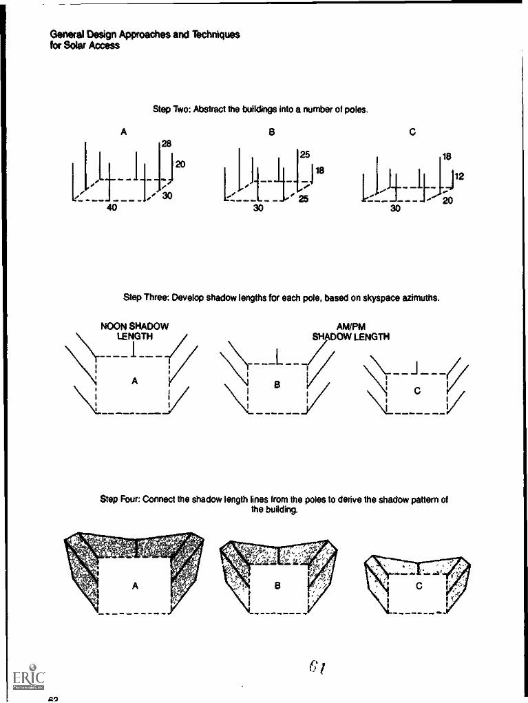
General Design Approaches and Techniquesfor Solar Access
Step Two: Abstract the buildings into a number of poles.
Aais
I
i I 1 ___I dial
itti
s C
.30
Step Three: Develop shadow lengths for each pole, based on skyspace azimuths.
NOON SHADOW ANI/PMLENGTH SHADOW LENGTH
AI
i c
--__I--_17/
Iy /\:_
1
1
1
, /411 .11= 10 . m. eme.
I
4. mllo ..1m. .
Step Four: Connect the shadow length lines from the poles to derive the shadow pattern ofthe building.
I
AO

General Design Approaches and Techniquesfor Solar Access
Step Five: Make a template of the building shadow patterns and arrange the shadow patternson the site so that shading is minimized.
The procedure is different on sites where theslope changes radically. Instead of using shadowtemplates for the various building types, the siteplanner or developer must construct individualshadow patterns for each structure, based on theterrain. Slope direction and gradient change theshadow lengths and shadow patterns. Theshadow lengths tables in Appendix III must beconsulted for each change in terrain and buildingdimension.
A similar approach can be used when the de-veloper does not intend to build the project butmerely intends to subdivide and improve the landfor others to develop. in this case, the developeror site planner must approximate the final dimen-sions and locations of the buildings on the lots.The easiest way to do this is to examine the zon-ing ordinance and other regulations. Zoning ordi-nances frequently establish maximum height re-strictions, and this height standard can be used
BLDG. "C"SHADED BYBLDG. "A"
TO SOUTHWEST
to develop approximate shadow lengths forhypothetical poles for future buildings. Similarly, ifmaximum density is desired, then the buildablearea of the lots can be approximated by takingthe subdivision plat and subtracting zoning set-backs from the lot line boundaries. What resultsis a definition of the largest possible structuresthat legally can be built on the site. Figure 52 il-lustrates this technique.
The developer or site planner might find thisapproach too restrictive to meet density objec-tives because it assumes a maximum buildoutthat may never occur (even if it is allowed underlocal regulations). As an alternative the developercan examine nearby, completed developmentswhose residents represent the target group formarketing. The site planner or developer can as-sume that similar buildings of similar dimensionswill be built in his subdivision and can base hisshadow pattern templates on these existingstructures.

General Design Approaches and Techniquesfor Solar Access
I
Figure 52. Shadow Patterns for Subdivision Lots
014...=ee w. . me IM .11. *IN . Alp
MAXIMUMBLDG.
HEIGHTUNDERZONING
. Im ..
I1
$
$ MAXIMUM$
BUILDABLEI AREA
II
FRONT IL
SETBACK
LOT SIDELINE VIEW
Ii-------.1LOT PLANLINE VIEW
.. a I a .. , i .. , .
Figure 53. North Shadow Projection Distance Compared to Shadow Pattern of a Pole
N SHADOW PROJECTIONDISTANCE
64

General Design Approaches and Techniquesfor Solar Access
Figure 54. North Shadow Projection Table
RATIO OF NORTH PROJECTION OFSHADOW LENGTH TO HEIGHT OF
SHADOW CASTING OBJEC rSouth NorthSlope 20% 15% 10% 5% Flat 5% 10% 15% 20% Slope
25' 1.1 1.2 1.3 1.4 1.5 1.6 1.8 1.9 2.130" 1.4 1.5 1.6 1.7 1.9 2.1 2.3 2.6 3.035' 1.6 1.8 2.0 22 2.5 2.8 33 3.9 4.840° 2.0 2.3 2.5 2.9 3.4 4.0 5.1 6.8 10.245° 2.5 2.9 3.4 4.1 5.1 6.8 10.4 21.548° 2.9 3.5 4.2 5.3 7.2 11.2 25.4
*These figures are approximate. Al some of the higher latitudes and steeper slopes, rounding off may result in slight error. Forfurther discussion. see Appendix
Analyzing Shadow Projections
A north shadow projection is the furthest pointnorth that a shadow reaches. Analyzing northshadow projections is a quick method to deter-mine solar access for a proposed developmentand can be used as a rough method to assessthe effect of shadows in a residential project. Inorder to prevent shading of the collector, theplanner or developer can use the shadow projec-tion technique to determine the minimal distanceneeded between the collector and objects lyingto the south of it. This method is most useful indevelopments where south-wail access is an ob-jective and where streets are oriented in aneast/west direction.
While the shadow pattern technique is themost accurate representation of how much spacea specific shadow covers, a shadow projection isstill useful for a broad-scale analysis of an entiredevelopment. The shadow projection distancecan be used, for example, to determine theminimum spacing between two rows of town-houses or detached structures situated northand south of each other, and, ultimately, to de-termine the maximum development density that
will meet solar access requirements. Techniquesfor determining density using this technique arepresent in Appendix IV.
As figure 53 shows, there is a geometric rela-tionship between shadow length and northshadow projection. The greater the shadowlength, the farther north the shadow projectiondistance. The very factors that affect shadowlength-nortlVsouth slopes, latitude, and shadowazimuth angles-also affect the north shadowprojection distance. In most cases, the shadowprojection distance will be less than the shadowlength during the morning and afternoon, but itwill be greater than the noon shadow length foran object of uniform height.
Shadow projections can be derived from figure54. The values in the table represent the ratio ofthe north projection of a shadow's length to theheight of the object casting it. To find the projec-tion of a 10-foot pole at 30 degrees north latitudeon a flat surface, multiply 1.9 (the value for thenorth projection obtained from the chart) by 10.Thus, 19 feet is the furthest distance north thatthe shadow of a 10-foot pole at 30 degrees northlatitude will reach (between the morning and af-ternoon cutoff points).
65
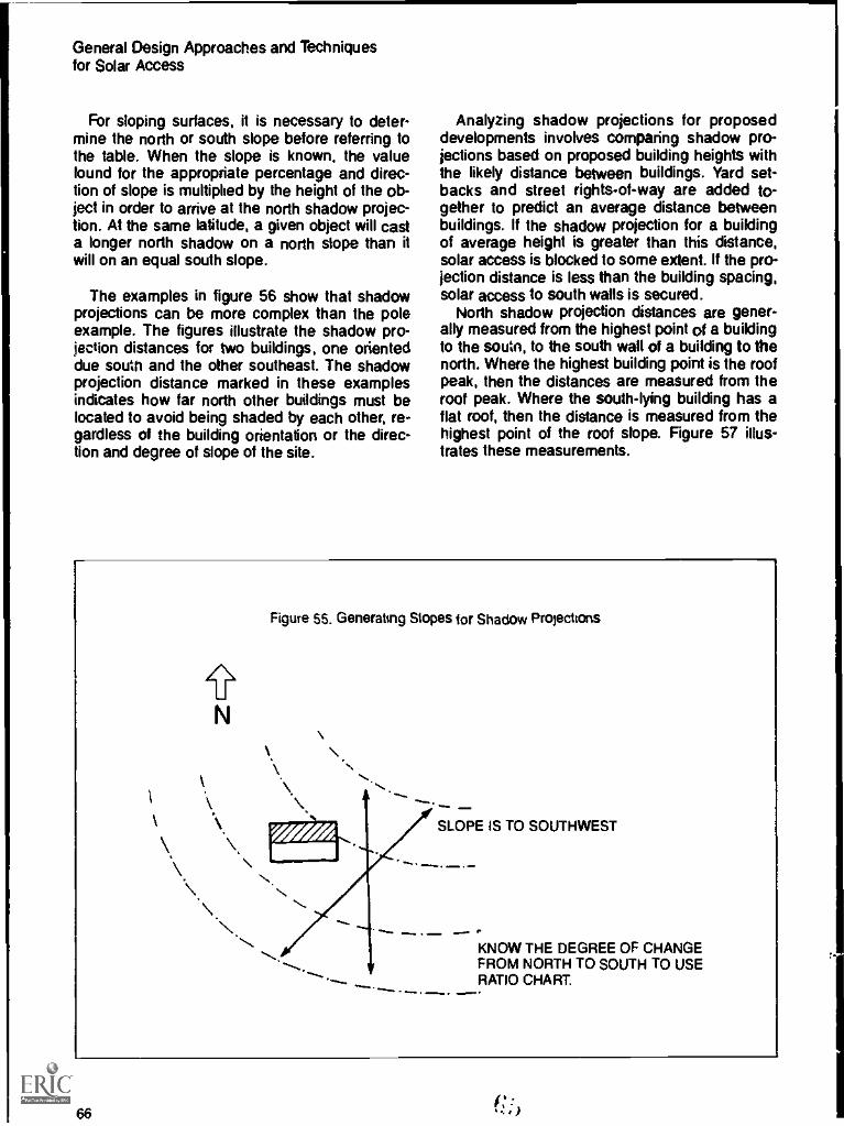
General Design Approaches and Techniquesfor Solar Access
For sloping surfaces, it is necessary to deter-mine the north or south slope before referring tothe table. When the slope is known, the valuefound for the appropriate percentage and direc-tion of slope is multiplied by the height of the ob-ject in order to arrive at the north shadow projec-tion. At the same latitude, a given object will casta longer north shadow on a north slope than itwill on an equal south slope.
The examples in figure 56 show that shadowprojections can be more complex than the poleexample. The figures illustrate the shadow pro-jection distances for two buildings, one orienteddue south and the other southeast. The shadowprojection distance marked in these examplesindicates how far north other buildings must belocated to avoid being shaded by each other, re-gardless of the building orientation or the direc-tion and degree of slope of the site.
Analyzing shadow projections for proposeddevelopments involves comparing shadow pro-jections based on proposed building heights withthe likely distance between buildings. Yard set-backs and street rights-of-way are added to-gether to predict an average distance betweenbuildings. If the shadow projection for a buildingof average height is greater than this distance,solar access is blocked to some extent. If the pro-jection distance is less than the building spacing,solar access to south walls is secured.
North shadow projection distances are gener-ally measured from the highest point of a buildingto the soutn, to the south wall of a building to thenorth. Where the highest building point is the roofPeak. then the distances are measured from theroof peak. Where the south-lying building has aflat roof, then the distance is measured from thehighest point of the roof slope. Figure 57 illus-trates these measurements.
I
l
Figure 55. Generating Slopes for Shadow Projections
i;
SLOPE IS TO SOUTHWEST
KNOW THE DEGREE OF CHANGEFROM NORTH TO SOUTH TO USERATIO CHART
- ....., . ......
66

General Design Approaches and Techniquesfor Solar Access
Figure 56. Shadow Projections for Two Buddings
MN a... .mlir
THESE DISTANCES ARE THE NORTH PROJECTION OF THE BUILDING SHADOW.
Figure 57. Measuring North Shadow Projection for Flat and Peaked Roofs
v.SHADOW 60' SHADOW
PROJECTION PROJECTION
FLAT ROOF: MEASURE FROM NORTH WALL PEAKED ROOF: MEASURE FROM ROOF PEAK

General Design Approaches and Techniquesfor Solar Access
To illustrate the use of this technique, considera hypothetical development on a 5 percent northslope at 40 degrees north latitude. The local reg-ulations require a 40-foot road right-of-way and30-foot setbacks for front and rear yards. Eachlot is 100 feet deep and designed along east/weststreets. Each budding is 40 feet deep and has apeaked roof running parallel to the building axis.The zoning ordinance allows a maximum buildingheight of 35 feet. The developer wants to knowwhether buildings of this height will shade thesouth walls of adjacent buildings to the north.
Using the north shadow projection table in fig-ure 54, the developer can assume that a 35-foottall building will cast a shadow 140 feet to thenorth of the roof peak (4.0 x 35' = 140). Thisshadow projection distance is compared to the
separation distances (30' + 40' + 30' = 100')between buildings to the north and south of theroadway; see figure 58. Because the northshadow projection exceeds the separation dis-tance, it can be assumed that the building to thenorth will be partially shaded by a 35-foot tallstructure lying to the southeast or southwest.
To obtain south-wall access to buildings northof the roadway, it becomes necessary to reducebuilding heights. If the separation distance be-tween buildings is known, building heights can beincrementally reduced until the north shadow pro-jection distance is less than or equal to the sep-aration distance. Figure 59 shows that a 28-foottall building can be built without shading thesouth waNs of buildings to the north of the road-way.
A
Figure 58. South-Wall Access Limited by 35-Foot Tall Building to South
140' NORTH SHADOW PROJECTIONt4
20' 20' 30' 40' right-of-way
30'20'
Figure 59 SouthWall Access Protected by a 28Foot Tall Building
112' NORTH SHADOW PROJECTION1
20'
<=IN
20' 20' 3040' Rightof-Way
68

Specific Design Strategiesto Protect Solar Access
Laying Out RoadsEast/West Street OrientationOrientation Guidelines for East/West StreetsUsing Street Width as Solar Access Buffers
Lot Design StrategiesLot Orientation on East/West StreetsReducing Frontage on EasVWest StreetsLot Layout on North/South Streets
Siting Strategies for Single-Family DetachedHousingEqualizing Solar AccessZero Lot Une Strategies for Solar AccessUniform Setback Requirements for Solar AccessPlacement of Garages. Carports. and Fences
Siting Strategies for Low-Rise MultifamilyHousingApplying Siting Techniques from Single-Family to
Multifamily HousingSite Planning Multifamily Housing as Large-Area
UsesSiting Strategies for High-Rise HousingPlanning On Space
Using Open Space as a BufferUsing Open Space as the Location for Central
Collectors
Conventional site planning involves the planningof roads, lots, buildings, open space, utilities, andother public facilities within a development. Siteplanning for solar access adds yet another di-mension to these conventional planning con-cerns. This chapter offers a number of alternativesolar-access design strategies for each functionalaspect of site planning. In some cases, the choiceof strategy may be confirsd to only a few alterna-tives by local regulations or the peculiar charac-teristics of the site, whereas other developmentsituations may permit several alternatives to beconsidered concurrently.
A note or two before getting into the specifics.First, many of the examples presume passivespace heating and south-wall access. Since thisis the most restrictive sitaation for solar energyuse if access can be protected for this use ofsolar energy, then it can also be protected for ac-tive space heating, natural cooling, and domesticwater heating. By protecting south-wall access, adeveloper opens options for future solar energyuse, because protecting a south wall from shad-ing also automatically protects the south roofarea.
Second, if any of the suggested strategiespose undue restrictions on other developmentobjectives, the developer can consider changingthe type of solar access. For example, if achiev-ing south-wall access prevents the developerfrom meeting his density objectives, he canswitch to solar technologies using rooftop ac-os. Moreover, the developer should recognizethe interrelationship of various design elements.Changing street orientation, for example, canalso change lot and building orientation. The de-tailed site plan should be kept consistent with thedevelopment objectives presented in the orelimi-nary site plan and site eva:*atior..
V. 69

Specific Design Strategies toProtect Solar Access
Figure 60. Subdivision, Davis, California
Laying Out Roads for Solar AccessThe street and road system of the developmentis one of the major design elements of the siteplan. Not only is it the single greatest construc-tion, but it acts as the framework for lot and build-ing layout, greatly affecting solar access to thedevelopment. In designing a road system for anew residential development, the site plannercan incorporate the following solar access designstrategies into the conventional design objectivesof the transportation system.
East/West Street OrientationOne of the best ways to assure proper solarbuilding orientation, especially under conven-tional development practices, is simply to runstreets from east to west. This makes possiblesouthern orientation of the greatest nu'nber of
70
1.11.M1liva
buildings. The technique is being used in solarsubdivisions in California. Figure 60 shows asubdivision in Davis, California, with all solar-equipped homes. Most streets run from east towest, with short north/south collector streets.This development was a PUD, but even con-ventional developments can use a similar streetlayout.
Unfortunately, it is not always possible to orientstreets from east to west. Topography may de-mand that streets follow elevation contours tominimize grading costs and to prevent erosionand runoff problems. But collectors (and build-ings) still can receive adequate sunlight even ifnot oriented due south; that is, considerable vari-ation from an east/west orientation is possiblewithout severely limiting solar access to thedevelopment.
Where site constraints dictate that streets beoriented north/south, solar access can still be
C!)
'MaiiiiiiMME=MMI

protected by reevaluating the type of solar ac-cess; for example, by using roof-mounted collec-tors facing south or by modifying the design ofthe building. In some areas of the site, however,the topographic constraints may be so over-whelming that only conventional developmenttechniques can be used.
Orientation Guidelines for East/West StreetsBuilding orientation, as noted above, generallydepends on street orientation. Because properbuilding orientation saves energy in mosthomesand is absolutely crucial in homes usingpassive space heatingit is useful to considerregional orientation guidelines for streets in newresidential development. Figure 61 divides thecountry into a number of geographic regions,based on shared climatic characteristics (such as
Specific Design Strategies toProtect Solar Access
temperature, humidity, and heating and coolingneeds). in figure 62, an optimal street orientationis suggested for each region. The range of orien-tation angles from the east/west idea is only ap-proximate, with some variation caused by suchfactors as topography, existing buildings, roadalignments, or weather conditions (morning fog,for example). But these roadway orientationguidelines will assure proper lot layout and build-ing orientation for solar access and energyconservation.
Of course, regional guidelines for street °dentation must be used cautiously, especially forsites near regional boundaries. Nor is this theonly possible way to delineate regions. As re-search continues on the use of climate as a de-sign tool, other ways to categorize the variousclimatic regions of the country undoubtedly willbe developed.
Figure 61. Regional Climate Zone Map
71
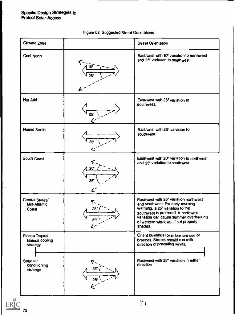
Specific Design Strategies toProtect Solar Access
Figure 62 Suggested Street Orientations
Climate Zone Street Orientation
Cool North
F'East/west with 10° variation to northwestand 25° variation to southwest.
25°
---
Hot And East/west with 25° variation tosouthwest.
< .-25°
Humid South East/west with 25° variation tosouthwest.
25'
4:
South Coastc..20,"LL,---- 1\
East/west with 2O variation to northwestand 35° variation to southwest.
Ai35° .-,
1'Central states/
Mid - Atlantic
Coast
1.-- --r - ...,t,,
East/west with 25° variation northwestand southwest. For early morningwarming, a 25° variation to thesouthwest is preferred. A northwestvariation can cause summer overheatingof western windows, if not properlyshaded.
1----r----7-,,--.11s-,
h.'
FloridaNaturalstrategy
Solar airconditioningstrategy
Tropicscooling
Onent buildings for maximum use ofbreezes. Streets should run withdirection of prevailing winds.
r-- /..25° / -,
East/west with 25° variation in eitherdirection.
25° '
:7 1
72
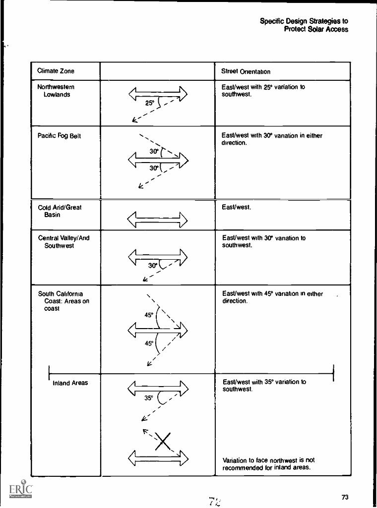
Specific Design Strategies toProtect Solar Access
Climate Zone Street Orientation
NorthwesternLowlands
East/west with 25° variation tosouthwest.
25°
Pacific Fog Belt ..30°
East/west with 30° variation in eitherdirection.
30°
Cold Arid/GreatBasin
East/west.
< 15Central Valley/And
SouthwestEast/west with 30° variation tosouthwest.
.
30°
ic
South CaliforniaCoast: Areas oncoast
[Inland
\ \45° ( \ \
\_\N
.East/west with 45° venation in eitherdirection.
,
45° ( //
14
Areas
,East/west with 35° variation tosouthwest.
Variation to face northwest is notrecommended for inland areas.
35°
R
X\<
wsI
73

Specific Design Strategies toProtect Solar Access
Using Street Width as Solar Access BuffersStreet width can be used to separate buildingsfrom each other and to increase the distance be-tween solar collectors and potential obstructions.The road rightof-way reservation required inmany subdivision regulations can be modified insome situations to increase the distance betweenbuildings on either side of the street or to increasethe distance between a building and a street treelying to the south. in developments with severalhousing types on east/west streets, placing tallerbuildings on the south side of a street and shorterbuildings on the north side can help reduce shad-
ing, as figure 63 illustrates. Major streets or high-ways can be especially good solar buffers if theyare effectively located, because they do not needsolar access. lb use roads this way is better thanusing valuable open space as a solar buffer.
Using streets as solar access buffers is notappropriate in northern latitudes, where sunangles are low and shadows are long. Narrowerstreet width standards are more appropriate insouthern climates, where the emphasis should beon ways to minimize pavement heating by the hotsummer sun and to allow more effective shadingof streets by street trees. Of course, present and
74-7
a 1

Specific Design Strategies toProtect Solar Access
Figure 64. Lot Orientation on Intercardinal Streets
Maintaining south orientation of housing where streets are shifted from the east/west axis. Angle A isformed by the intersection of north/south with a line connecting the southwest corner of one house to
the southeast corner of its western neighbor.
future traffic load and circulation objectives mustalso be considered, as must be the requirementsof local regulations for non-PUD developments.
Lot Design Strategies for Solar AccessIn most conventional single-family developments,the long axis of each lot is perpendicular to thestreet, while the long axis of the home is parallelto the street. In most townhouse developments,both the long axis of the building and the longaxis of the lot are perpendicular to the street. Indesigning a project for solar access, the de-veloper wants eac". building to be oriented to thesouth, that is, with its long axis running east/west. He can design the development with thestreets oriented from east to west, so that the lotsand buildings also are oriented east to west. Orhe can ignore the street orientation and orient
each lot with long axis running north/south, sothat conventionally sited buildings are oriented tothe south.
Lot Orientation on East/West StreetsThe corollary to east/west street orientation isnorth /south orientation of the long axis of lots.When it is not possible to run streets from east towest, lots still can be platted so that they haveproper solar orientation. if streets must run fromthe northwest to the southeast, for example, thenlot lines can be laid out at oblique angles to thestreet, as pictured in figure 64. The diagramshows the tong axis of the lots running from northto south, making it relatively easy to site thehouses for maximum solar orientation. Note:Angle A (shown in figure 64) must be 45 degreesor greater to prevent the south walls of thehouses from being shaded by their neighbors.
75
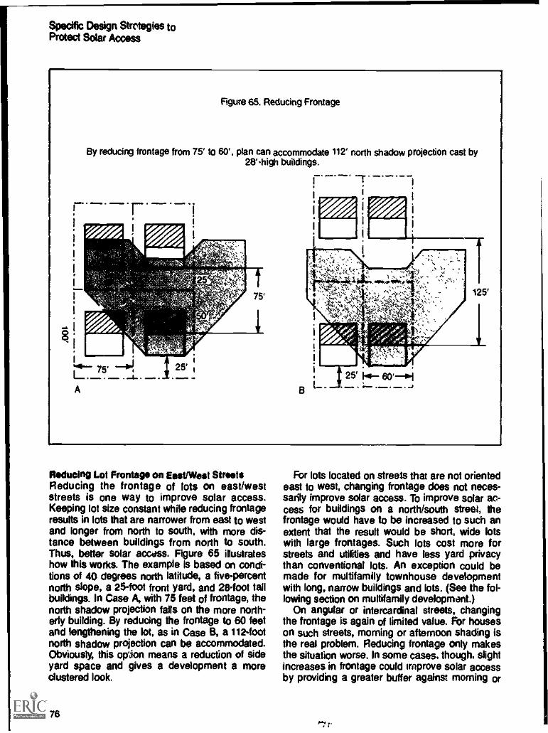
Specific Design Strategies toProtect Solar Access
Figure 65. Reducing Frontage
By reducing frontage from 75' to 60'. plan can accommodate 112' north shadow projection cast by28'high buildings.
r.... ..
A
Reducing Lot Frontage on Eest/West StreetsReducing the frontage of lots on east/weststreets is one way to improve solar access.Keeping lot size constant while reducing frontageresults in lots that are narrower from east to westand longer from north to south, with more dis-tance between buildings from north to south.Thus, better solar access. Figure 65 illustrateshow this works. The example is based on condi-tions of 40 degrees north latitude, a five-percentnorth slope, a 25-foot front yard, and 28-foot tailbuildings. In Case A, with 75 feet of frontage, thenorth shadow projection falls on the more north-erly building. By reducing the frontage to 60 feetand lengthening the lot, as in Case B, a 112 -footnorth shadow projection can be accommodated.Obviously, this opJon means a reduction of sideyard space and gives a development a moreclustered look.
76
For lots located on streets that are not orientedeast to west, changing frontage does not neces-sarily improve solar access. To improve solar ac-cess for buildings on a north/south street, thefrontage would have to be increased to such anextent that the result would be short, wide lotswith large frontages. Such lots cost more forstreets and utilities and have less yard privacythan conventional lots. An exception could bemade for multifamily townhouse developmentwith long, narrow buildings and lots. (See the fol-lowing section on multifamily development.)
On angular or intercardinat streets, changingthe frontage is again of limited value. For houseson such streets, morning or afternoon shading isthe real problem. Reducing frontage only makesthe situation worse. In some cases, though, slightincreases in frontage could improve solar accessby providing a greater buffer against morning or

1.II
afternoon shading. Whether a change in frontageimproves solar access in these cases dependson the specifics of the site.
Changing frontage to promote solar access inmultifamily housing depends on the type of mul-tifamily units. For duplexes, reducing the frontageon easVwest streets improves solar access bydeepening the lots, Provided that the long axis ofthe duplex parallels the street. The situation isnearly the same as for the single-family housesshown in figure 65.
For townhouses or apartment buildings, reduc-ing frontage is a less useful tool for protectingsolar access. Townhouses (and apartments)usually are not subject to frontage requirementsbut are governed by such requirements as floorarea ratios. Even when such developments mustmeet a frontage requirement, it is often impos-sible to improve solar access by changingfrontage.
Specific Design Strategies toProtect Solar Access
Lot Layout on North/South StreetsWhen streets cannot be oriented from east towest, even on a diagonal, siting buildings forproper solar orientation becomes more of a chal-lenge. There are two ways to maintain proper lotorientation on north/south streets: by combininglots and by using "flag" lots.
Combining lots is especially useful where thelot layout has already been dictated. Two lots thatabut each other on the north or south can be re-platted; the buildings lying close to each other inan east/west orientation provide maximum solaraccess, as figure 66 illustrates. The techniquecalls for a departure from conventional single-family, detached housing design. The houses pic-tured are duplexes, although it would be possibleto use detached units in a similar way. The de-veloper must consider whether the added benefitof proper solar orientation balances any marketdesire for more traditional building siting.
Figure 66. Combining Lots for Proper Orientation
1 I
M. i .
d
I
INSTEAD OF THIS
NORTH
1 I f.....
1
1
i_._ _ _ . r____ _ _1_ _ _ ._ .TRY THIS
77

Specific Design Strategies toProtect Solar Access
Figure 67. Using Flag Lots for Proper Orientation on North/South Streets
fl.NORTH
Figure 68. Mobile Home Orientation on North/South Streets
i
_._._.-.1_
I
.[./.. .imp
rei .=. . .
. _ rm., . ...
I-tlitliCCI-Q)
NORTH
78

Specific Design Strategies toProtect Solar Access
Figure 69. Reducing Setback to Equalize Access
A. Traditional Setback and Unequal Access
115'
30' setback
N
B. Reducing Setback to Equalize Access
95'
20' setback
Hypothetical site, flat at 40N. latitude, with a shadow projection of 87.5' for 25'-high buildings.
In A, only buildings to the North of road right-of-way have south-wall access. By reducing setback by10' (from 30' to 20'), all structures have south-wall access in B. This affects shading only by buildings;street trees must be regulated to prevent shading problems.
The flag lot technique is used when the streetsare spaced so far apart that four lots can be runin an east/west direction, with the "pole" of theflag connecting the inner lots to the street. Figure67 shows how. This technique is unconventiona'and might not be allowed under local regulations.Although it may result in higher utility connectioncosts for the inner lots, it does have the benefit ofcreating conventional spacing between the endsof buildings.
Where buildings are fairly short, as in mobilehome developments, it is possible to have goodsolar access even on north/south streets. Seefigure 68.
Siting Strategies for Single-FamilyDetached Housing
Along with site planning for streets, planning forsolar access requires consideration of the siting ofbuildings. The discussion of building siting beginswith single-family detached housing.
Equalizing Solar AccessIn developments where buildings are sited in thetraditional way with front, side, and rear yards,some buildings usually have better solar accessthan others. As figure 69A shows, in higher den-sity dist.icts the rear yards of buildings sited on
79

Specific Design Strategies toProtect Solar Access
east/west streets may be relatively small. As aresult, the distance between houses that back oneach other (in the illustration, 75 feet) is less thanthe distance between houses that face eachother (115 feet). Consequently houses on thesouth side of the street are shaded.
But it is not always necessary to change thezoning provisions to improve solar access for theshaded buildings. Depending on latitude and top-ography, adequate solar access may be pro-vided under standard setback requirements bymeans of a simple adjustment. By reducing thefront yard setback and increasing the rear yardsetback, the distance between houses that backon each other and houses that face each othercan be made nearly equal. in effect, this movesall the structures closer to the street and im-proves solar access to the houses on the southside of the streetas figure 69B illustrates.
The precise change in yard space depends onthe latitude, the topography, and the orientationof the structures. Generally, this technique ismost effective on east/west streets, although itmay also work on diagonal streets. Lots andhouses on streets oriented from north to southwould not gain anything from this strategy, be-cause the streets do not offer any additional buf-fer from shading.
This remedy works only for shading by adja-cent buildings, not by street trees. Unless vegeta-tion is carefully selected and sited, movinghouses nearer to the roadway could mean thatthe houses and their collectors would be shadedby the street treesactually decreasing ratherthe.) increasing solar access. This strategyshould, therefore, be considered only when vege-tation is strictly controlled according to the designstrategies discussed in Trees and Landscaping.
ROAD RIGHT-OF-WAY
ALL BUILDINGS ARE SITED AT NORTH LOT LINE.
80 79

Specific Design Strategies toProtect Solar Access
MP'
Figure 71. South Building-Orientation
\MIlp./\. .
*\
'\ .>,/
>{?BUILDINGS FACESOUTH EVENTHOUGH LOTSDO NOT \ / N
Zero Lot Line Strategies for Solar AccessOne design option that is particularly useful forprotecting solar access in any development is avariation of zero tot line siting, an innovativetechnique in which buildings are sited so thatthey abut property lines. For solar access, allow-ing buildings to abut the north lot lines providesthe greatest possible yard area to the south ofeach building. Figure 70 shows how this works.
Siting buildings this way gives eachhomeowner maximum control over the place-ment and size of accessory buildings and trees.It has the added benefit of increasing the dis-tance from trees and buildings on adjacent tots,which usually are not under the control of thehomeowner. This increased distance is especiallyvaluable if shading by street trees is a problem.The distance between buildings is essentially thesame whether a zero lot line or traditional set-back approach is taken, but the distance fromtrees along the street is increasedespecially forbuildings on the north side of the street. It alsomeans that the owner has greater personal con-trol over the buffer area between his building andbuildings and trees to the south.
This technique is equally applicable to housesand lots on east/west or north/south streets. Thezero lot line technique may also be useful if lotsare large enough on north/south streets andbuildings are sited with their sides to the street formaximum solar orientation.
The zero north lot line technique may also beuseful for lots and buildings on diagonal streetsApplied to lots on a street that run from northeast
to northwest to southeast, the provisions allowfor siting the building in the northernmost cornerof the lot; one or two of the corners of the build-ing will touch the northeast or northwest lot lines,as figure 71 illustrates. In this situation, there stillmay be substantial shading from adjacent build-ings in the morning and afternoon.
In most cases, the zero lot line techniqueshould be applied to every building and lot in aproject. Otherwise, there could be significantshading, especially for lots and houses on east/west or north/south streets. If one building issited on the north lot line and another building issited in the center of the adjacent lot, the latterbuilding may substantially block the south-wallsolar access of the first building in the morning orafternoon hours.
The use of this technique may involve sometradeoffs with other development objectives.First, the application of this technique can sig-nificantly change the design of residentialneighborhoods. Houses to the south of an east/west street would front the road, while buildingsto the north would be set back a greater distancethan might be the norm for the community. Thisunusual massing of structures along both sidesof a street is, however, likely to be more an ap-parent than an actual tradeoff. In such subdivi-sions a sense of visual balance is maintained byhomeowners on the nortn side of the street install-ing privacy fences and garages along the streetfront. The apparent mass of these structures ap-pears to balance the visual mass of the homesclose to the road on the south side of the street.
S 1 :a1

Specific Design Strategies toProtect Solar Access
A second drawback is that utility connectionsmight be more expensive for the lots on the northside of the street. because they are farther fromthe utility easement within the road right-of-way.This cost is balanced, however, by the savingsfor utility hookups to houses on the south side ofthe street.
Finally, moving houses so close to the streetmay limit the occupants' privacy. Privacy may bepreserved, however, by putting in fences or land-scaping to shield the house from public view.
Uniform Setback Requirements forSolar Access ProtectionUnder traditional setback practices, buildings in adevelopment may be staggered in distance fromthe street or real lot line to meet minimum yardrequirements. This can pose a shading problemin the morning or aiternoon. Uniform buildingsetback, on the other hand, protects solar ac-cess. if all the south building walls line up (ornearly line up), the buildings cannot shade eachother. Figure 72 illustrates the solar access bene-fits of uniform setbacks over staggered setbacks.
Remember, too, that the minimum 45-degreesetback angle is always measured from thenorth/south axis, as shown in figure 73.
Placement of Garages, Carports, and FencesThe site planner must also plan garages, fences,and other accessory structures so that they donot shade the south walls of buildings requitingsolar access. The principle is simple. Accessorystructures can be sited to the north of the mainbuilding whenever possible, if they do not causea pmblem on adjacent, northerly property. Whengarages or fences are sited to the south, theymust be set far enough back from the main build-ing that their shadows do not encroach on thecollector's skyspace. Siting them as close aspossible to the southern property tine is desirablefor this reason. Figure 74 shows how this works.
When zoning regulations require setbacks forfences or carports, it is sometimes necessary tonegotiate with public officials for permission tosite these structures for good solar access. (Thecompanion guidebook on regulations can behelpful in such an effort.)
Figure 72. Uniform versus Staggered Setbacks
fi.N
STREET
iI
SHADEDHOUSE
!
S 1
82

Specific Design Strategies toProtect Solar Access
Figure 73. Measuring Setback Ans les
PLAN VIEW OF TWO BUILDINGS
I1
I SETBACK ANGLE
S
MEASURE SETBACK ANGLE FROM THE NORTH/SOUTH AXIS.
Figure 74. Placement of Garages
B
.0.
Lo...,...m............4
<=3
S 2 .

Specific Design Strategies toProtect Solar Access
PARKING LOT
<=3 N
Siting Strategies for LowRiseMultifamily Housing
Low-rise multifamily housing includes all attachedstructures fewer than four storiesduplexes,quadrupiftes, townhouses, rowhouses, and mul-tistory flats. As suggested in the chapter on designapproaches, these structures provide special op-portunities for site planning; because they fre-quently cover a great deal of land, they offer thesite planner more flexibility in locating accessoryuses in a way that protects the solar access of themain structure. In many cases, though, the sametechniques for single-family detached housing areequally appropriate for low-rise, multifamilybuildings.
84
Applying Siting Techniques from Single-Familyto Multifamily HousingThe siting strategies for maximizing solar accessto single-family developmentseast/west streetorientation, zero lot lines, and uniform setbackrequirementscan also be used for multifamilydevelopments. In some respect, the latter aremore flexible than single-family projects becauseof their greater reliance on active solar collectors.Active collectors can be roof-mounted, ground-mounted, or mounted on the roof of an accessorybuilding (such as a carport) and, therefore, do notrequire south-wall access. Moreover, the gener-ally greater height of multifamily buildings raisescollector surfaces above most obstructions.
SS

Modifying setbacks to maximize solar accesscan be particularly useful for duplex units sited inthe same way as single-family homes. The mod-ification can be used to improve south-wall accessfor the duplex units and prevent unequal solar ac-cess caused by small rear yards. With townhouseunits, the approach is less appropriate. Usuallythe ends of the townhouse units face the streetsor the backyard, so any change in setback im-proves access to only one of the narrow walls ofthe building, which is no great boon to solarenergy collection. In any case, townhouses arelikely to use rooftop collectors, which are not af-fected by a change in setback.
The zero lot line approach can be used for allvarieties of multifamily housing to improve solaraccess. Whether the units are individual duplexesor large apartment buildings, siting the building onthe north lot line improves the control over shad-ing caused by nearby buildings. Larger multifamilydevelopments are usually subject to flexible set-back, lot coverage, or perimeter requirementsrather than traditional yard requirements, and any
Specific Design Strategies toProtect Solar Access
code provisions that address the siting of suchprojects should be made flexible enough to permitzero lot lines.
Uniform setbacks are useful for all types ofmultifamily housing if south-facing buildings lineup with each other and any shading from eastand west buildings is kept outside the setbackangle. If zoning provisions for multifamily districtsare flexible, then a specification for uniformsouth-wall setbacks may not be necessary.
Site Planning Multifamily Housing asLarge-Area UsesIn addition to the techniques used for single-familyhousing, low-rise multifamily housing can benefitfrom special techniques that solve its unique prob-lems. Automobile parking, for example, is a muchmore important consideration in multifamily de-velopments than in single-family projects. But itcan be an asset. For example, a parking lot sitedto the south of a structure can be used to create ashadow buffer. Alternatively, the unbroken
Figure 78. Contour Housing
I..........
20' WIDE ONE-WAY STREET
CONTOUR ROW HOUSINGORIENTED SOUTH ON 20% SOUTH SLOPE
'p84 85

Specific Design Strategies toProtect Solar Access
shadow belt that a long row of two- or three -storyrowhouses casts to the north makes an ideal loca-tion for roads and car parking. (See figure 75.)
Low-rise multifamily housing can also be sitedto take advantage of slopes that increase insola-tion and solar access. Special techniques can beapplied in these situations, but the cost of gradingand cut-and-fill development has to be consid-ered. Row housing is well suited to south slopesup to 20 percent, provided that the structuresparallel the contour. At low latitudes, gentle northslopes can also provide good solar access. Onvery steep sites, consider long blocks of buildingsbacked into the hillside along the contour andparalleled by one-way access roads, as figure 76illustrates.
Except on south slopes, contour developmentis not recommended as a way to increase solaraccess. it requires too much grading and site pre-paration to justify the cost. Stepped constructionthat uses cut-and-fill site preparation (as shown infigure 77) also improves solar access, but it, too,is both costly and likely to produce erosion orsedimentation problems.
Wing Strategies for High -Rise HousingTall buildings cast big shadows, and they are gen-erally located near other tall buildings. In suchsituations, it is crucial to draw the shadow patternsof adjacent buildings in cross-section, so that thebuilding can be planned with its lower floor having
Figure 77. Stepped Construction on West Slopes
86

Specific Design Strategies toProtect Solar Access
RESIDENTIAL
OM NMNimInrNM ME
Nor
Figure 78. High-Rise Shading
0EXISTINGBUILDING
Min
NON-RESIDENTIALUSES
.
In urban sites, draw shadows of adjacent buildings in section to see what partof the new building wilt be shaded.
Lr
limited solar access. These floors can be used fornonresidential uses, such as parking, as shown infigure 78.
Planning Open Space for Solar AccessIn larger projects, most developers are required toprovide open space for recreational or environ-mental purposes and a growing number aredoing so voluntarily. Developers and site plannerscan use the strategic location of open space andbuffer strips to protect solar access.
Using Open Space as a Solar Access BufferWhen a projecta mixed-use development, forexampleis to contain some relatively tall build-ings, open space can be located to the north of
the tallest buildings to buffer shorter buildings tothe north against the tall building's shadow. Seefigure 79.
The problem is that open space used for parksor recreation needs sunlight. Using such space tobuffer buildings from shadows means that playareas would be shaded for much of the day. Incolder climates, this would mean shortening theperiod of the park's usefulness. The problem mustbe considered on a case-by-case basis. If theopen space is heavily wooded, for example, theshading is less of a problem, since the trees pro-vide some shading too. Or, if the taller buildingsare only three or four stories high, then a narrowbuffer strip would be sufficient to prevent shadingand open more park land for maximum sunlight.Only high-rise buildings create a significant prob-lem here.
86 87

Specific Design Strategies toProtect Solar Access
88 87
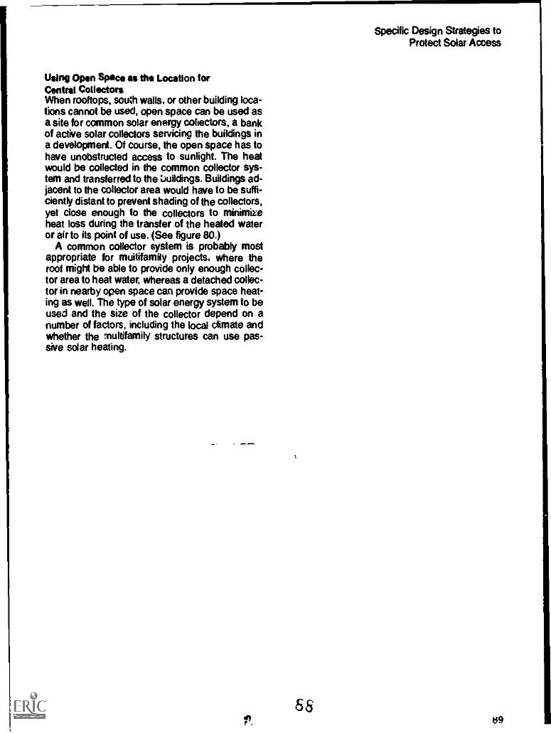
Specific Design Strategies toProtect Solar Access
Using Open Space as the Location forCentral CollectorsWhen rooftops, south walls, or other building loca-tions cannot be used, open space can be used asa site for common solar energy collectors, a bankof active solar collectors servicing the buildings ina development. Of course, the open space has tohave unobstructed access to sunlight. The heatwould be collected in the common collector sys-tem and transferred to the buildings. Buildings ad-jacent to the collector area would have to be suffi-ciently distant to prevent shading of the collectors,yet close enough to the collectors to minimizeheat loss during the transfer of the heated wateror air to its point of use. (See figure 80.)
A common collector system is probably mostappropriate for multifamily projects, where theroof might be able to provide only enough collec-tor area to heat water, whereas a detached collec-tor in nearby open space can provide space heat-ing as well. The type of solar energy system to beused and the size of the collector depend on anumber of factors, including the local climate andwhether the multifamily structures can use pas-sive solar heating.
&8ii 09

Trees and Landscaping
Solar Access and Existing VegetationNew Vegetation: Project Landscaping
Species SelectionMature Height and Crown BreadthTiming of Leaf Seasonr)ensity of Winter TwigsLocation of New Plantings
Maintaining Vegetation: Pruning and ThinningGuidelines for Plantings
To protect solar access, it is more difficult to planfor trees than for buildings. Shading characteris-tics change from species to species, from seasonto season, and from year to year. Many develop-ers include landscaping in their plans, but gener-ally the primary concern of landscaping plans isaesthetic. For solar access planning, though, it isnecessary to give as much attention to trees as tothe other components of the development. Theyhave an effect not only on solar access but also onthe energy efficiency of the development. Treesand other vegetation can reduce cooling needs insummer by shading and reduce heating needs inwinter by acting as windbreaks. These reductions,in tum, make it easier for a solar energy system tocompete with conventional methods of spaceconditioning.
This chapter discusses three topics: existingvegetation, planning new trees that are part of aproject landscaping plan, and tree maintenance.Because vegetation is so specific to a region's.,:imate and to a site's characteristics, it is difficultto provide a detailed discussion on the manage-ment of vegetation for solar access protection.The chapter presents some basic guidelines thatmust be used as the developer or site plannerproceeds with a project.
Solar Access and Existing VegetationOne of the most difficult tradeoffs in planning forsolar access involves the presence of trees on asite to be developed with solar homes. In manycases there is simply no way to avoid taking downat least some trees to provide access to southwalls and rooftops. Sometimes the preservation oftrees is required by law, and the developer has tocontend with local officials to protect solar access.
01%91

Trees and Landscaping
Figure 81. Vegetation Types Analyzed on Base Map
The presence of trees on a site forces the de-veloper to answer some important questions: Howheavily forested is the site? How many trees mighthave to come down? Are there areas that couldbe used for central collectors? What tree speciesare present? Will they let in enough light in thewinter? Can some trees be just trimmed or topped?The developer also has to decide which is thestronger selling point, solar access or a nicecanopy of trees. Perhaps some compromise canbe reached, so that some buildings can be givensolar access while the most valuable or beautifulstands of trees are preserved.
The planning problems caused by existing treesmay be eased in several ways. First, analysts ofthe site prior to planning the development mayshow certain areas to be freer of trees thanothers. If such areas happen also to be on southslopes, then they clearly are suited for placementof solar housing, as figure 81 illustrates. Evenparts of the site that do not face south, if lessforested than other parts, may be good for solarhousing. By looking at the steepness of the gradeand the extent of forest cover, the developer canpinpoint areas to be avoided and areas that showpromise.
Second, some tree species present more prob-lems than others. Evergreen trees, for example,are a problem all year round. Deciduous trees areusually better for solar housing, although somedeciduous species are worse than others in termsof shading. Species with dense branching struc-tures, that grow to great heights, and that keeptheir leaves into the winter present greater prob-lems and bigger shadows for a longer period thancertain other species. (This is discussed further inthe next section on planting new vegetation.) If thedeveloper or site planner can determine whichtree species cause the least shading problemsand can couple this with a judgment about theaesthetic value or rarity of tree species, he will beable to identify the most suitable building areas.
Third, if a site is unevenly forested, the woodedareas can be used for open space or buffering. Inmany projects, open space is either required byordinance or donated by the developer. In a pro-ject with solar homes, forested areas of the siteare a natural choice for open space.
Finally, when shading from existing trees is aproblem. a developer can consider using a centralcollector system, a large array of collectors thatserves a number of buildings. These collectors
92 90
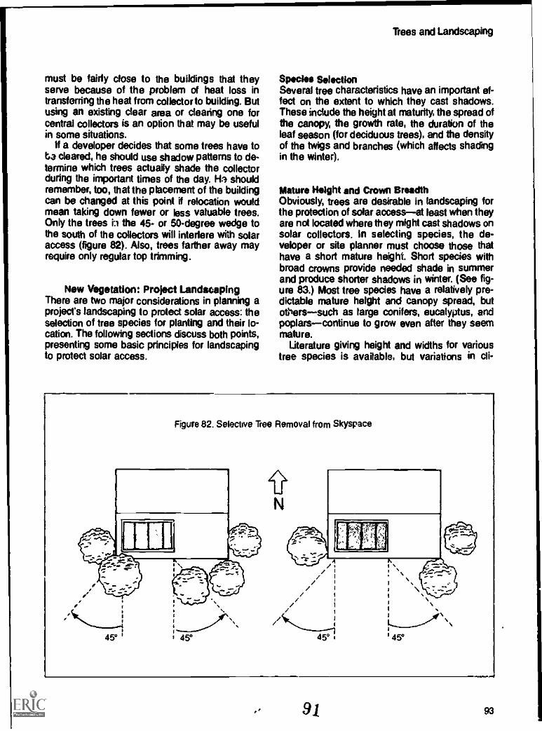
must be fairly close to the buildings that theyserve because of the problem of heat loss intransferring the heat from collector to building. Butusing an existing dear area or clearing one forcentral collectors is an option that may be usefulin some situations.
if a developer decides that some trees have toba cleared, he should use shadow patterns to de-termine which trees actually shade the collectorduring the important times of the day. Ha shouldremember, too, that the placement of the buildingcan be changed at this point if relocation wouldmean taking down fewer or less valuable trees.Only the trees the 45- or 50- degree wedge tothe south of the collectors will interfere with solaraccess (figure 82). Also, trees farther away mayrequire only regular top trimming.
New Vegetation: Project LandscapingThere are two major considerations in planning aproject's landscaping to protect solar access: theselection of tree species for planting and their lo-cation. The following sections discuss both points,presenting some basic principles for landscapingto protect solar access.
Trees and Landscaping
Species SelectionSeveral tree characteristics have an important ef-fect on the extent to which they cast shadows.These indude the height at maturity, the spread ofthe canopy, the growth rate, the duration of theleaf season (for deciduous trees), and the densityof the twigs and branches (which affects shadingin the winter).
Mature Height and Crown BreadthObviously, trees are desirable in landscaping forthe protection of solar accessat least when theyare not located where they might cast shadows onsolar collectors. in selecting species, the de-veloper or site planner must choose those thathave a short mature height. Short species withbroad crowns provide needed shade in summerand produce shorter shadows in winter. (See fig-ure 83.) Most tree species have a relatively pre-dictable mature height and canopy spread, butdie'ssuch as large conifers, eucalyptus, andpoplarscontinue to grow even after they seemmature.
Literature giving height and widths for varioustree species is available, but variations in cli-
Figure 82. Selective Tree Removal from Skyspace
A/
9 1 93

Trees and Landscaping
Figure 83. Crown Height and Breadth for Solar Access
COMPARISON OF TREE FORMSY2 < Yi AND X2 > X,. SO, WIDE, SHORT TREES GIVE BETTER S.D.E PATTERNS BOTH
SUMMER AND WINTER.
X = BENEFICIAL SUMMER SHADEY = DETRIMENTAL WINTER SHADE
mate, soil characteristics, the availability of water,and ether factors make it worthwhile to consult alocal nurseryman to find out exactly how variousspecies will behave.
Timing of Leaf SeasonAlthough deciduous trees obligingly provide shadein the summer and let in the sun in the winter, theirtiming is somMimes less than perfect. ideally,leaf-outthe g owth of new leavesin springwould correspond with the end of the heating sea-son and leaf-drop would correspond with the startof the heating season. For the site planner thismeans finding tree species that have a growingseason that coincides as closely as possible withthe time when the solar energy system will not bein use. In the spng. this is usually no problem;but in warm winter climates cold periods canoccur long after some species have a full leafcover. In such cases, trees that leaf-out early(such as weeping willows and certain poplars)should not be used where they might shade aspace heating collector or south glazing. Similar
problems also can occur with species that have aheavy bloom of flowers early in the spring (almondtrees, for example) and others that retain fruit ordead leaves late into the fall or all winter long.(Some oaks, for Jxample, keep most of theirleaves through the winter.)
In fall, there can Pe a considerable overlapinsome circumstances, as much as two monthsbetween the arrival of cold weather and completeleaf-fall. During this period, solar energy is readilyavailable, and tree species with early leaf-fallshould be selected for planting. Besides the gen-eral leaf-fall characteristics of different species,there are several factors that can affect leaf-fallwithin a species. They are:
Watering and feeding practices. Extended irri-gation and late summer fertilizing can boost lategrowth and slow leaf-fall. Conversely, stoppingirrigation in mid-summer can force early leaffall.
Pruning. Since unpruned trees generally losetheir leaves before pruned ones do, minimizepruning and never prune in late summer.
94 92

Trees and Landscaping
Figure 84. Variations in Bare Twig Density Give Variations in Penetration of Winter Sunlight
,e7Ir rryN1-
Wind. Sheltering trees from wind encouragesleaf retention. Sheltered trees may delay theirleaf-fall two or three weeks compared to similartrees in windy locations.
These practices can be used to control leaf-fallin order to synchronize it more closely with thebeginning of the heating season.
Density of Winter TwigsWhen existing deciduous trees or new plantingsstand to the south of a collector, their bare winterbranches block sunlight to a certain extent, de-pending on species, pruning, and maturity (figure84). Living Systems' preliminary study of unprunedtrees of commonly used species in Davis, Califor-nia, shows that bare winter branches reduce a col-lector's insolation from 30 to 80 percent.
The bar chart showing bare branch shading(figure 85) shows a range of radiation blockage fora number of different species as well as for indi-vidual species. The shaded portion of each barshows the variation in light meter readings ob-tained for the various samples; the unshaded por-tion indicates the minimum shading that can beexpected for each tree species. The extent of thisvariation depends on the number of readingstaken for each tree species and the conditionsunder which the data were collected. This infor-
matron is likely to vary with the area of the countryand the types of trees.
Unfortunately, this kind of information is notlikely to be available for common tree species, al-though radiation blockage information may existfor forest canopies. But forest canopies are notstreet trees, and it is doubtft.i whether forestry in-formation is applicable to individual trees orsmaller clumps of trees. Therefore, site plan-ners may have to generate this informationthemselves.
This task is relatively simple. On a dear winterday, the site planner uses a light meter to deter-mine the amount of radiation falling on a spotshaded by a tree's bare branches and compares itto the amount of radiation falling on an unshadedspot near the tree. An incident meter or a commonreflective meter lifted with a diffusion lens worksbest. Alternatively, a common light meter can befocused on a matte, uniform grey card. Changesin radiation are read oft the meter dial every fewpaces as the meter is carried through theshadows cast by the tree's bare branches andtwigs. Several trees of each species should beexamined; the readings for each species are thenaveraged It makes no difference whether the lightmeter reads in f-stops, foot-candles, or someother measurement of radiation; only the differ-ence between the shaded and unshaded mea-surement matters.
93 95
1

Trees and Landscaping
Figure 85. Bare Branch Sun Penetration for Various Tree Species in Davis, California
100%...
80%w-!,....
... ... - . ... ... ...
....... . -. ... ,- --. ... --- --- ...
40%
20%
0
3IDZ
"<1'
-- -.
0Z
=":0,
.1 te,Tc
L.
cr
fD-ID
:.. -777s..
-I
aniumm.P
' P *s:
:1"'0 s
IU)
These are some of the factors that should beconsidered when selecting species for landscap-ing a solar project. The site planner or developeris well advised to consult a local nurseryman orother expert familiar with local vegetation.
Location of New PlantingsThe second major consideration for landscapingis the location of trees to be planted. While theprecise location always depends on specificconditionsthe topography of the site, the kindsof housing to be used and so onit is possible togive some general guidelines for the location oftrees to protect solar access.
Simply stated, large trees should not be plantedwithin the 45- or 50-degree wedge of solar sky-space to the south of a solar collector, as figure 86shows. Large trees should be planted either to thenorth of buildings or solar collectors or to theluth of areas not used for collectors (that is, to
the south of roads, parking areas, or industrial
96
areas). Climatically undesirable or exceedinglysteep land unsuitable for buildings is especiallygood for large tree groupings. Smaller groupingsshould be located where they will not interfere withsolar access. Usually, this can be accomplishedby siting the taller trees first and smaller tmesnext.
As planning proceeds, the shadow patterns ofproposed trees should be diagrammed in planview. Unless they are low enough not to block theNetter sun, trees should not stand south of cone:-tors in an arc between southeast and southwest.In most climatic zones, buildings should be siteddirectly to the east or west of trees. Especially athigher latitudes, if the tree has a high crown and aclear trunk, siting close to the south house is best.
Trees should be planted in groups to assuremaximum solar access. Trees in groups cast over-lapping shadows, creating less total shaded areathan does the same number of separated trees. Itis also easier to plan for one larger shadow thanfor many smaller ones. (See figure 87.)
94

Trees and Landscaping
Figure 86. Tree Siting for Solar Access
A typical planting scheme to allow solar access to south walls. Site tall trees carefully.
1,
Note 87. Stands of Trees
A dozen treo in two clumps leave large expanses with good access. Dispersed. they shade out mostof the site
I. 9597

Trees and Landscaping
Taller frees should be planted on the south sideof Meets rather than on the north. The width ofthe street and the setbacks act as a buffer to pre-vent the taller trees' shadows from reaching thesolar collector. Although this is a relatively uncon-ventional approach, it born protects solar accessand shades the pavement in the summer.
The closer trees are to the south wall of thehouse, the shorter they must be. This meansplanting low, shrub-like trees or hedges near thehose and taller trees farther away. The developercan imagine a light plane running from the sun tothe south wall of the buildings unler which treesmust fit (figure 88).
Evergreen trees should be limited to the northside of buildings, both because they shade allyear round and because they protect houses fromstrong winter winds. In those parts of the UnitedStates where the prevailing vinter winds are notgenerally from the north, evergreens should be
located so that they block the winds without block-ing solar access.
Maintaining Vegetation: ;Jruning and ThinningWhether used to heat or cool, to shade houses orstreets, trees usually need pruning or thinning, askill requiring knowledge and experience. It isbest to landscape with trees that require little prun-ing until they attain their maximum size. Figure 89shows how thinning works. If thinning becomesnecessary, trees should be pruned from the bot-tom, not from the top. The crown should bethinned rathw than topped, because top pruningencourages dense twig growth, which can blockneeded sun, as figure 90 illustrates. Conversely,cutting the lower branches can increase solarpenetration in winter, especially for trees plantednear singlestory buildings at high latitudes.
LOT LINE
Figure 88. Plantings on South Lots
...-.
--- - I
I1
1LOWI SHRUBS 11- 20'
1-SETBACK
40'I
601..80,
20 1 30' i 50'TREES: TREES TREES
I I
J
I.0T LINE
9806

Trees and Landscaping
Figure es. Thinning Trees
1. NOW
BEFORETHINNING
Figure 90. Topping Trees
2. AFTERTOPPING
3. NEXT YEAR
AFTERTHINNING
4. IN 3 YEARS"TIME
Guidelines for PlantingsIn selecting and locating plantings, the developershould:
Consider mature height when selectingspecies.
Consider the breadth of the canopy.
Consider whether deciduous or evergreenspecies are appropriate.
Consider the timing of the leaf season. Does itcoincide closely with the beginning and end ofthe heating season?
Consider the density of twigs and branches forboth sun and wind penetration.
Plant trees outside the 45- or 50-degree arc tothe south of solar collectors.
Keep the south wall of houses free of shadowsbetween the critical hours on December 21.
Use plan and section drawings to evaluateshadows, conflicts with solar collectors, andbeneficial summer shading.
Remember that domestic water healing collec-tors, swimming pools, and gardens need sun-light during the summer when dwellings,streets, and other paved areas need shade.
Place evergreens to the north of collectors (ornorth of the entire project) if north winter windsare a problem.
Plant trees in groups rather than individually toattain maximum solar access.
Plant taller street trees on the south side of thestreet, shorter ones on the north.
Place tall trees away from the solar collectorand short trees or bushes near the collector.
n rr 99

Wes and Landscaping
Regional Vegetation Guidelines
Although the vagaries of local climate and thespecific nature of the vegetation itself makes it dif-ficult to give exact instructions about landscaping,
it is possible to go into somewhat greater detail forvarious climate zones of the country. The follow-ing are guidelines for tree selection and locationfor the various regions of the country shown infigure 91.
98100

REGION Solar AccessGuideline
Pacific Fog Place taller trees inBelt community open
space, rather thanputting them dose tobuildings.
Regional Vegetation Guidelines
Wind Buffer ShadeGuideline Guideline
Trees and Landscaping
Figure
Low evergreeh wind- This is the only build- 4._ Nbreaks, hedges, and ing climate with noshrubs are important need for shading infor protection from summerthe wind. hi.
North-westernLowlands
Low solar angles re-quire the use of shorttrees with broadcrowns. For the longheating season de-ciduous species thatget their leaves latein the spring but leafout quickly are thebest choice.
Evergreenwindbreaks can beused whenever theydo not interfere withsolar access.
4 N
GreatBasin/ColdArid
The best location fortrees in this region isdirectly north of build-ings. When trees arelocated to the south,use short, broad, de-ciduous trees thatpermit maximumwinter sunlight pene-tration.
Summer shading can ... Nalso be accomplishedby moveable ar-chitectural devicesthat will not shadecollectors in winter.
AndSouthwest
SouthernCaliforniaCoast
Deciduous speciesplanted south ofbuildings will providemuch-needed shadeduring the hotseason.
Keep south wall andother collectors clearto the south.
On the shoreline,evergreen wind-breaks are desirableif they do not blockaccess.
On inland sites,vege-tation can be plantedto funnel oceanbreezes for cooling.
Shade paved areasand outdoor useareas as much aspossible during thehot season.
Shade trees shouldbe planted near westwalls, windows, andpaved areas.
Hot Arid Provides shade andpreserve access bymassing trees to theeast and west ofbuildings.
Ground cover plant-ings help cool theenvironment whilemaintaining access,but will still keepbreezes flowing be-neath tree canopies.
99 101

trees and Landscaping
REGION Solar AccessGuideline
Regional Vegetation Guidelines
Wind Suffer ShadeGuideline Guideline
Figure
Cool North Trees planted to thesouth of the buildingshould be short,broad, deciduousspecies with opentwig patterns.
Plant other trees forshelter from wind, tothe north and west ofbuildings. Evergreensare best for wind-breaks in winter.When solar accessmay be blocked, uselow shrubs andhedges to divertwind.
4-N
Central Keep the south yardsU.SAJ free of trees.Mid-AtlanticCoast
Use evergreens tobuffer buildings fromthe wind, but do notblock solar access.
Concentrate planting 4- Nin belts immediatelyto the north of build-ing rows, shadingstreets when possi-ble. Plan vegetationcarefully, usingshadow Patterns,when trees are likelyto connict with solaraccess.
HumidSouth
Use broadleafed,deciduous species,keeping dear ofsouthwall or roof ac-cess. Trees should bemassed in lines orgroups immediatelyto the north of build-ing rows.
Use trees with cleantrunks and lightbranching to allowbreeze penetration.
Some lightly twigged Ndeciduous trees arepossible immediatelyto the south ofbuildings.
South Coast Preserve all existingtrees even at the ex-pense of losing solaraccess. If possibleallow solar access torooftop water heatcollector& Deciduousspecies immediatelyto south of buildingscan allow partial sunto south glazing androoftop collectors inwinter.
102
Use tree species withbare branches forbreeze penetration.
100
Shade is more valu-able than sun in thisclimate.
N

REGION Solar AccessGuideline
Regional Vegetation Guidelines
Wind Buffer ShadeGuideline Guideline
Trees and Landscaping
Figure
Florida Preserve all existing Use bare trunk Shade all paving,Tropics trees even at the ex- species for breeze windows, and walls
pense of losing solar penetration. and, where possible,access. If the site is all roof areas.already well forested,presenting the oppor-tunity to shade mosthouses completelyuse a central collec-tor bank for domesticwater heating.
N
101103
Two Examples of SolarSite Planning
Determining Planning CriteriaSite SelectionSite Analysis and Preliminary Site Plan
ClimateVegetation and Site Characteristics
Conventional DevelopmentPreliminary Site PlanDetailed Site Plan
Streets, Lots, and Building SitingLamiscaping
ginned Unit DevelopmentPreliminary Site PlanDetailed Site Plan
Streets, Lots, and Building SitingLandscaping
The preceding chapters have presented the fun-damentals of planning and development to pro-tect solar access and promote proper solar orien-tation. Drawing on this basic information, thischapter demonstrates how a development planwith solar access protection as a primary objec-tive might be developed for a conventional sub-division and for a planned unit development. APUD offers a number of advantages in designinga project for good solar access, but a more con-ventional development also can be laid out toreach this end. Both examples use the same20-acre site in the southern end of California'sCentral Valley, near Fresno, at 37 degrdes northlatitude. The cgonventionai plan shows an_singt&__family residences, each having adequate solaraccess. The PUD plan will have a somewhathigher density and a mix of housing types.
The decision-making process for planning thedevelopment follows this format:
Determination of planning criteria;
Site analysis and preparation of a preliminarysite plan; and
Development of a more detailed site plan,showing individual lots and dwelling locations.
Determining Planning CriteriaThe site is located in a county with fairly conven-tional land-use controls. The parcel is zonedAR-1, agricultural/residential with single-familydetached housing and accessory structures al-lowed by right. The zoning establishes large lot-size requirements-1 dwelling unit per 7,000square feet of lot area resulting in an overalldensity of 5.8 dwelling units per acre, or a totaldevelopment potential of about 120 dwelling unitson the site. Subdivision regulations have typicalroad and infrastructure standards governingutilities, sewage, water supply, and roads. In ad-
102105

Two Examples of Solar Site Planning
Figure 92. Site Topography
1337'
100014.
99Ombo.
.11,
TOTAL AREA20
ACRES
dition, there are requirements for open-spacededication and for the preservation of existingtrees and other major vegetation.
The community also has a PUD provision in itszoning, which can be invoked by application tothe city council for a rezoning. The PUD provi-sion is also typical, allowing both a variety ofhousing types (single-family detached, attachedlow-rise, and mid- and high-rise buildings) on thesame parcel, provided that the project complieswith specified standards. As an incentive, thePUD provision allows a maximum density of 7dwelling units per acre, creating a developmentpotential of up to 140 dwelling units for the 20-acre parcel. As with the conventional zoning pro-visions, there are requirements for environmentalstandards, tree preservation, and open space.
Based on these regulatory standards, the de-veloper has selected the following developmentobjectives for the site:
South-wall access for all dwellings;
Maximum energy efficiency, with solar collec-tors providing most of the seasonal heating re-quirements and natural Cooling;
106
The preservation of views to themountains;
A central recreation facility andspace, meeting the minimumquired for project approval;
Sierra Nevada
common ipenstandards re-
Maximum allowable density under both ordi-nance provisions (conventional and PUD) con-sistent with market demand in the region. Forthe PUD development, this means a housingmix of single-family detached, low-rise at-tached, and mid-rise apartments.
Site SelectionThe site shown in figure 92 was chosen becauseit is essentially flat, with a long easthvest axisthat maximizes its southern exposure and pre-sents no solar acce 'ts obstructions. Close todowntown, schools, and a commercial center, itis served by utilities and has a superb view of themountains.
103

Site Analysis and Preliminary Site Plan
ClimateCalifornia's Central Valley has mild but cloudyand foggy winters. In the hot season, Junethrough September, the temperature averages100PE It is dry, and relief from heat can be pro-vided by shading, ventilation, and roof pondcoolers. The winter winds and the north winds inthe spring, when air temperatures are moderate,can be a significant climatic factor. Summerbreezes are light and variable. The growing sea-son lasts all year
Two Examples of Solar Site Planning
Vegetation and Site CharacteristicsThe site surface is composed of grass and darkearth; the only trees are along the north border,where shadow conflicts are minimal. There areneither trees nor tall structures on the adjacentlots. This site enjoys beautiful views of the SierraNevada to the north and east. The major roadway,on the east edge of the property, connects the sitewith the local school and a downtown area lessthan a mile away. The combination of flat terrain,good weather, and short distances make bike rid-ing an attractive mode of transportation. Figure 93shows the details of the site analysis.
104107

Nff
Two Exiinp les of Solar Site Planning
Figure 94. Preliminary Site Plan: Conventional Development
0 " # t *a OM /0%v a
Figure 95. Housing Types
:= ;s 105008

Conventional Development
Preliminary Sits PlanThe overall concept (shown in figure 94) stressesthe key points:
The entire site is suitable for housing: there areno solar access conflicts.
All local streets run east/west to allow housesto be oriented south. Straight street layout isused for simplification, but curvilinear streetswould also be appropriate.
The roadways form view corridors to the northand east.
Detailed Sits PlanStreets, lots, and building Ong. The major con-siderations are:
The street and lot layout allow south orienta-tion of houses.
The houses are located to the north end ofeach lot to minimize solar access conflictswith other buildings.
Two Examples of Solar Site Planning
The layout of individual buildings and trees isbased on shadow patterns.
The general types of single-family housingshown in figure 95 are planned for this project. allusing (or having the potential to use) passivesouth-facing collector area for space heating,rooftop active systems for water heating, and roofponds for natural cooling.
House A One -story house on east/west axiswith roof pondHouse BOne-story house with partially flatroof areaHouse COne-story shed-roofed houseHouse 0Ilvo-story flat-roofed houseBuilding ECarports
Figure 96 shows one possible layout of housingon the site. Shadow patterns indicate that all dwell-ings have south-wall solar access. Allowing solaraccess to the south wall ensures adequate sun forrooftop water heating systems. South yards aremade as large as possible on most lots.
106 toe

I
4111101 /alp iivafa....0.4,4;.1" 411.4111"1"°'
trt't " is fek11
_ _.I. -
rf (
1111:,\111110, rjp7,,170.11410,-"
c:
lip AnitilS; , 4r.
well!rPN,
1-411kidiZkallik4010I 1- ( )41 IN, 7 W 4
,
jos Li,
:4ponliiip_s"4:111 *AEI.
4. 11 M
141B.,*1 4 W. mei t'l'AS, Pat ikS4r1P- b$4111itialemiAikrim 1' *
.
-
_fit telt'
411.44Zsio Vrof A.. Z"." '11
4110; A JP MP I
pp,pp,
4.; 4 k. -14,1:111:
waJIII s-sco i AN ion'
'mu wag So! vip OAS rm. ^11
*4' 4, a'- '.1 ;', p .11 "1.11,4,
s & A !,1r
A.A
AL.
AV. VIOVIAv1
gal 8.01.ira,7 "'1.4sra virire ail ap ikk; '',F=4 de

Two Examples of Solar Site Planning
.ei nap' ir
pr30'4,4r'r,L-
0114;,4:66VE1X1Ps
111 1111111
'Pi el I IN 111
AR; 440
Figure 99. Site Master Plan: Conventional Development
0 2,114 1.4 "- *; ;iaroi;ir !om;iplippifoi
Imp Si ea
11111 iff
ir.71 Fool;Pi inagn NE IN ' lig pi
4.171-Wk ii'7147iiw 4.
Y.w. la pi = -NP
till Ile7=119
MIIIMIp'
PIN IL Pi 1 "II
-ler me
IIII Win Inni In
Landscaping. For planning purposes, a fewtypes of trees and shrubs were chosen; ranging inheight from 15 feet to 40 feet, each group has bothdeciduous and evergreen species. Figure 97shows the December tree shadows for these
For planningplanning purposes, a deciduous tree shouldbe evaluated as if it were evergreen, because itsbare branches block a significant amount of sun-light This * a very conservative approach, sincemany passive systems still work even whenshaded by bare branches. At higher latitudes, thisapproach may be too restrictive.
Figure 98 shows a layout for trees superim-posed on the housing layout. A significant numberof trees have been used without shading anysouth walls of the dwellings.
The site plan is completed by combining thebuilding and tree shadow plans in a manner con-sistent with the development objectives. The re-sidling plan is shown in figure aa
Planned Unit Development
Preliminary Site PlanThe major site uses, presented in figure 100, canbe summarized as follows:
Housing is grouped in dusters, each dusterhaving a focal open space.
A centralized community open space and re-creation center is linked to the clusters.
The tallest building, a mid-rise apartment, is lo-cated at the north edge of the site.
Auto circulation is kept to the periphery of thesite, and a bike/pedestrian path is used forinternal traffic.
The commercial center lies at the intersection ofthe two existing roads.
The highest density housing is located closestto the existing roads.
108 111

Two Examples of Solar Site Planning
The existing barn and fruit trees are used as anagricultural center.
The open spaces double as storm drainage andpercolation areas.
Detailed Site PlanStreets, lots, and building siting
All access streets run east/west to allownorth/south lots.
Only lots with roof clerestory collectors,buildings (see above, figure 35) do not runnorth/south. Clerestories gain solar accessthrough their roofs.
When possible, car circulation is kept to theperiphery in order to concentrate and inte-grate community and cluster open spaces.
Layout of individual buildings and trees isbased on shadow patterns.
All the general housing types used in the con-ventional neighborhood are used in the PUD, withthe additions shown in figure 101 as follows:
112
Apartment FAvo-story, four-unit apartmentbuilding. South wall requires solar access.
Apartment C-- Low -rise attached townhouses.Most are two-story although some one-storyunits are included. All require solar access tothe base of the south wall.
Apartment HAttached low-rise apartments.Solar access is through the roof for passivespace heating. South walls receive sun for halfthe day in winter. Private yard space is on theeast or west.
Apartment l--- Four -story, mid-rise apartmentbuilding. This is a single-loaded exterior cor-ridor plan to allow south access and cross-ventilation to all units. Patios are provided onthe south side.
Figure 102 shows an alternative housing layoutthat achieves south-wall and, in many cases,south-yard solar access for all dwellings. Carportsgenerally are located on the opposite side of thestreet along the southern edge of the neighbor-hood to maximize solar access to south yards.The following section drawings are used to de-termine best placements of carports:
1 09

Two Examples of Solar Site Planning
Figure 101. Apartment Types: PUD
110 113

Two Examples of Solar Site Planning
Alternative 1 in figure 102 shows carports ad-jacent to the houses. Solar access to thesouth yard is blocked by the carport in winter,but the street is half-shaded in summer.
Alternative 2 shows the carport on the south(opposite) side of the street. The shadow ofthe deciduous street trees allows increasedwinter sun to the larger south yard, but thestreet has minimal summer shade.
Alternative 3 shows that alternating streettrees and carports results in optimum sunand shade patterns.
Shadow patterns are developed for each of thehousing types; the buildings and shadow patternsare arranged on the site plan in various ways thatare consistent with the landuse diagram de-veloped earlier. Building placement is optimalwhen all south walls obtain the best solar access
and are not shaded by adjacent structures. Figure103 shows this arrangement.
Landscaping. As for trees, a process similar tothat used in the conventional development is usedfor the PUDthe tree types are identified andshadow patterns developed. The trees andshadow patterns are then organized on the siteplan to accomplish the major developmentobjectivesummer shading of yard areas andwest walls of structures and winter sun access tosouth walls and rooftops. Figure 104 shows theresulting tree plan.
Finally as in the conventional development, allthe elements are combined into a final site masterplan. Buildings and trees are located to achievethe best circulation, land use, and solar accessdevelopment objectives. Figure 105 shows thecompleted PUD development, fully planned forboth optimal solar access and conventional de-velopment goals.
Figure 102. Housing Layout Alternatives
Partial sun through deciduous tree
<=I NWinter sun to south yard plus summer shading
of street
114 111

*11 0401
*****
.11:
volts. e* .61411,4renr Gliveir oirtsverawerr,
U. ***** *. . . -.0**re
re
rorkeyi ri IP% rireor": 1111.slf F - ally. di
Of Irr I'll
41 111,
nor I *
P ,0414;' ".."
*. -11 Oar . 41
ffir I ir 4B
Ti/Oafir 41. 'reitte WWI
s t.
4P 41117-
1 ;I*
44Tel- floP ,-.300
s'..)
MP"' 117-711747rolll RN rillb..1, irtbitiA..."'". oil , ill 1 .1,404 i via,
I 5 ."115111.11 jiW
dal Br I...Nimrod, 1 4; pa_ 11
ENE 110?
awl El I °VW dilItft.vnw-_-4 4:rasigl' 1 Immilariri , I .. - I
°E.
ar
711111ir I 4,04. J
111; op
*ems i.14041,
ANEW IN "IL
11 W ....0 , orilew 1`;
au IN AU* 1 f MI
Mt, tiro 1/4"'"
5 I
:

1 -
1
ra..'Am "130. 11.01_
bA c 1110".5 2311r:0
%it**
1021iiirw_414 11 -te o
41 A .1 ".111 Mamma 4
-
!AI f+- 0 I.a
44 ill (.1 r.- 10.V
...r gAssru 0111 -s.
111,8 !.1111
,111141-_,T.,;
ON 1^ os_ilmI' 4.--_ ist'Av311
; -JAi=lstop _Jr
* 0120 .arIwo., go 9`)A.
14 ......"1,%;e:111tg:" fa Urge& 44i
Private Agreements toProtect Solar Access:Covenants and Easements
Restrictive CovenantsRestrictive Covenants as Banters to Solar Energy
Use and Solar AccessRestrictive Covenants and Solar Access
ProtectionAccommodating ChangeRestrictive Covenants of [Name of Development]in !Municipality or County)
EasementsSolar Skyspace Easement
The techniques discussed up to this pointsuggest strategies for protecting solar accessduring build out. But in order to be effective, solaraccess must also be protected after lots or build-ings are sold and occupied. A carelessly plantedtree, for example, can undo careful site planningand development design, and an addition to ahouse or a new garage can cast shadows acrossareas planned for the use of solar collectors.
It is for these reasons that developers mustconsider the use of private agreements to protectfuture access as well as to ensure existing solaraccess in new developments.
Private agreements are common techniquesused to preserve desirable characteristics of newdevelopments, such as common open space,large front yards, and architectural design. Pri-vate agreements suitable for solar access protec-tion include restrictive covenants and easements.Both types of agreements are familiar to de-velopers and public officials and are widely usedin the development process. They are especiallyattractive to developers and homeowners be-cause they offer a greater degree of private con-trol over restrictions affecting development. Thisflexibility is desirable because solar access pro-tection often involves restricting activities on onelot to protect adjacent parcels. If agreements canbe negotiated between lot owners, solar accesscan be assured with minimal public involvement.
Restrictive CovenantsThe most common private agreement is the re-strictive covenant. A restrictive covenant is a con-tract between two or more persons which involvesmutual promises of reciprocal benefits and bur-dens among consenting landowners. This meansthat all persons involved in a covenant benefitfrom it and that all are burdened by restricting anactivity such as the construction of an otherwiseallowable structure that could cast a shadow onthe solar collector of a neighbor. The covenant isconsidered restrictive because it requires the par-ties to restrict development opportunities. A re-strictive covenant is a covenant not to do some-thing, as compared with an affirmative covenantwhich is an agreement for the parties to take aspecific action.
Restrictive covenants are often created by adeveloper at the time a subdivision or develop-ment is approved by a local government. The re-strictions apply to lots within the development andare usually inserted into the deeds of all parcels to
114 117

'Private Agreements to Protect Solar Access:Covenants and Easements
be developed. The covenants may be enforced bythe developer, by a lot owner within the develop-ment, or, frequently, by a homeowner's associa-tion created to manage certain aspects of thedevelopment. Because these covenants oftenappear in the deeds, they are also called "deedrestrictions."
Some technical issues involving restrictive cov-enants arise because they are legal instruments.These issues include privity of estate and whetherthe covenant "touches and concerns" the land.Although these issues have a bearing on the en-forceability of the restriction, they do not concernthe developer and will not be discussed in thischapter. The existence of such problems sug-gests, however, that the developer should havethe proposed covenant reviewed by a lawyer, es-pecially if the covenant terms are unfamiliar. Thedevelopers major concern should be that thecovenant is enforceable and that it is likely to ac-complish its stated purpose, such as protectingsolar access or permitting the installation and useof solar energy equipment.
Restrictive covenants are similar to zoning in anumber of ways. Like public regulations, restric-tive covenants can guide private development de-cisions and can affect future, as well as existing,development within the subdivision or project.And, like zoning, covenants can create barriers tosolar energy use and solar access, or they canencourage site design and development to assuresolar access protection. In fact, restrictive cov-enants are sometimes called "private zoning" andare a major type of land use control in somecommunities (notably Houston. Texas).
Restrictive Covenants as Barriers to SolarEnergy Use and Solar AccessRestrictive covenants can affect developmentactions by lot owners. Covenants can prohibitcertain types of land uses, such as non-residentialuses in a residential development; restrict de-velopment to certain types of structures, such assingle-family detached housing; and even bar de-velopment altogether in certain areas of the site,such as open spaces or greenbelts.
Barriers to solar access and solar energy usemay arise inadvertently through the enforcementand operation of restrictive covenants. The de-veloper or homeowner's association may nothave intended to restrict solar energy use or solaraccess, but the application of the particular restric-tion nay do this nonetheless.
118
Developers who wish to encourage the installa-tion and use of solar energy collectors and theprotection of solar access should consider the ef-fects of restrictive covenants on these objectives.For example, covenants that control architecturalfeatures of structures within the development orthat require the planting or preservation of vegeta-tion between homes can discourage solar accessplanning.
Architectural standards are enforced in manysubdivisions for the purposes of maintainingproperty values and perpetuating desirableneighborhood characteristics. These standardscan be specified in several ways: (1) in a covenantthat requires, for example, all residences to con-form to an architectural style (French Provincial,Gothic, TUdor); (2) by an architectural reviewboard created by a covenant and empowered todeny or grant petitions to construct or materiallyalter dwellings within the subdivision; or (3) by ahomeowner's association which all landownersin the subdivision are bound by covenant to join.Regardless of how these standards are instituted,they can inhibit the installation of solar energy col-lectors if the design of the collectors is perceivedto be in violation of the covenant or against thearchitectural judgment of the board members orassociation officers.
A developer who desires to encourage the useof solar energy collectors and to promote somedegree of architectural harmony might considermodifying architectural standards within the de-velopment to accommodate solar collectors. Thedeveloper may choose to exempt some collectordesigns from the architectural standards, or atleast give collectors a presumption of architecturalcompatibility. Columbia. Maryland, for example, isdeveloping architectural guidelines for its architec-tural review board to use in evaluating the integra-tion of solar collectors into housing desilikely that such guidelines will have to be consid-ered by many other developments whose designguidelines now restrict solar collector installation.
Developers sometimes insert covenants in alldeeds to require landowners to maintain plantingsof vegetation near the property lines betweenresidences. Trees or tall hedgerows, shielding theresidences from outside view, afford greater pri-vacy than the landowners otherwise would enjoyand contribute to a more pleasing landscape. But,as was noted earlier, vegetation can affect accessto sunlight. Developers who wish to have bothbeautiful landscaping and solar energy collectorsmight consider prescribing maximum heights on

trees and other vegetation to prevent an obviousconflict between a covenant that requires vegeta-tion to be planted near the property line and onethat restricts shadow lengths across the propertyline.
Restrictive Covenants andSolar Access ProtectionA covenant provision to protect solar access isprinted below. In using this type of provision, itmust be remembered that the laws affecting re-strictive covenants vary from state to state. Thisexample is not meant as a model but may provideguidance to developers considering similar provi-sions in their own developments.
Restrictive Covenants of(Name of Development)in (Municipality or County)The following restrictive covenants are incorpo-rated in this deed and in all other deeds to parcelswithin the [name of development], which is lo-cated in [complete legal description of thedevelopment], as recorded in [legal records ofnamed county]. These covenants are bindingupon all present and future owners of land withinthis development with the same effect as if theywere incorporated in each subsequent deed.
(1) No vegetation, structure, fixture, or other ob-ject shall be so situated that it casts a shadow ata distance greater than 20 feet (6.1 meters)across any property line on December 21betweenthe hours of [9 a.m. and 3 p.m. Standard Time],provided that this restriction does not apply toutility wires and similar objects which obstructlittle light and which are needed and situated for
e prope in a mannerconsistent with other covenants in this deed. Byadopting this covenant, the landowners withinthis development recognize the desirability ofcreating and maintaining a common plan to en-sure access to direct sunlight on all parcelswithin the development for public health,aesthetic, and other purposes, specificallyincluding access to sunlight for solar energycollectors.
The two introductory sentences would prefacethe list of restrictive covenants, which in some de-velopments might number 20 or more. Of course,"covenant (1)" alone would be valid were it one in
Private Agreements to Protect Solar Access:Covenants and Easements
a list of other covenants if the list were validly in-corporated into a plat or deed and the covenantwere consistent with others in the list.
The phrase "vegetation, structure, fixture, orother objects," with the stated exclusions, In-cludes everything that might cast an appreciableshadow. It should not be necessary in the cov-enant to define individual words, but the plannershould be familiar with some of the key conceptsof the covenant.
"Vegetation" is self-explanatory. Discussions onthe different shading characteristics of treespecies are in the chaoter on trees .
"Structure" can be defined as "anything con-structed or installed or portable that requires fornormal use a location on a parcel of land. This in-cludes any movable structure located on landwhich can be used either temporarily or perma-nently for housing, business, commercial, agricul-tural, or office purposes." This is a modified defini-tion of one in American Law Institute, A ModelLand Development Code (1976).
"Fixture" may be defined as "personal propertywhich hat become so affixed to real property thatit cannot be removed without damage to the realproperty." For convenience. this definition some-times is included within "structure," by adding asentence such as, "It also includes fences,billboards, poles, pipelines, transmission lines,and advertising signs."
The restriction on shadows is designed to allowthe siting of solar energy collectors in yards aswell as on structures. The sample distance of 20feet in the covenant example should be adjusted,of course, to fit specific circumstances. The dis-tance selected will depend on such factors aslatitude, topography, lot size, and density of struc-tures. Developers considering covenant provi-sions similar to this examres n s a ing only across the northern lot line,instead of across any lot line. Whether a proposedobject will violate the covenant can be determinedwith knowledge of the latitude of the developmentand the proposed height and distance from the lotline of the object. The shadow length tables in Pre-liminary Site Planning can be used to calculatethe appropriate distances across any lot line, andthe shadow projection table in Appendix III can beused to calculate appropriate distances acrossnorthern lot lines.
Three hours before and three hours after solarnoon normally are adequate for the effective op-eration of solar energy collectors, both active andpassise. These times generally correspond to the
1 1 r 119

Private Agreements to Protect Solar Access:Covenants and Easements
45-degree azimuths used to define solar sky-space in most latitudes, but they also can be ad-justed. For example, six hours might be sufficientin winter, while-seven or eight might be neededduring the summer, when the solar energy systemmight be used for air conditioning. It is unrealisticto expect the land surface to be free of shadows atall times, because this would require an un-obstructed landscape from horizon to horizon.
Standard Time might be selected as the refer-ence time because of its practicality. Mean solartime might be preferable from a technical point ofview, because it corresponds more accuratelywith the position of the sun (the sun is directlysouth at mean solar noon), but Standard Time ismore familiar. This requires that mean solar timemust be converted to Standard Time by the drafterof the provision. The developer must keep in mindthe necessity of this conversion (which dependson the longitude of the development site) whenusing Standard Time in the covenant provision.
The covenant creates a common plan to pro-vide direct sunlight for rather broad purposes, notsolely for solar energy collectors. because this al-lows greater flexibility in the interpretation of thecovenant with regard to changing technologiesand neighborhood conditions.
Accommodating ChangeChanging circumstances and chanp;ng tech-nologies must be kept in mind when consideringcovenants of this type. Statutes in some stateslimit the applicability of covenant provisions. Statelegislatures, realizing that covenant restrictionsmight not be appropriate if enforced in perpetuity,limit the duration of such restrictions. For example,Georgia limits restrictive covenants to 20 years,Massachusetts to 30 years, and Minnesota to 40
pany to run utility lines across property. Ease-ments for solar access would be negotiated by in-dividual lot owners or by a developer with theowner of adjacent property. Essentially, the ownerof the burdened property agrees to keep areas ofhis property free of objects that could shade theneighboring solar collector. Easements are re-corded with a public agency, usually the city clerkor registrar of deeds.
A solar easement is a negative easement. Anaffirmative eatoment allows somebody to enter orcross land belonging to someone else. A negativeeasement prevents one landowner from doingsomething that otherwise would be allowed, suchas erecting a building that can cast a shadow on asolar collector on an adjacent lot.
Easements for solar access protection may bedrafted under existing property law in all states. Anumber of states, however, have adopted specificlegislation which sets forth the technical require-ments for solar access easements. A landownerconsidering solar access easements shouldcheck the state law to make sure that the ease-ments are both recordable and enforceable.
Shown below is a solar access easement.' Itscontent and format are only illustrative.
Solar Skyspace EasementSection 1. Estates Burdened and Benefited bythe Solar Skyspace Easement
[Grantor(s)] hereby conveys, grants, and war-rants to [ Grantee(s)] for the sum of [$____] anegative easement to restrict in accordance withthe following terms the future use and develop-ment of the real property of Grantor(s) recordedas follows with the [registrar of deeds] of[County':
years. These statutes allow parties to renew thecovenants and restrictions anytime before theend of the statutory term.
EasementsEasements are another type of private agreementthat can be used to protect solar access. Ease-ments are interests in real property that can betransferred like the property itself. One of the mostcommon examples is a utility easement, a rightpurchased or otherwise obtained by a utility corn-
'Thomas. Miller. and Robbins. Overcoming Legal UncertarnbesAbout Use of Solar Energy Systems. p 45
120
The boundaries of the solar skyspace for thesolar collectorfs) of Grantee(s) are as follows:
[Alternative (A)] All space over the above-described property of the Grantor(s) at aheight greater than [30 feet].
[Alternative (B) All space at a height greaterthan [30 feet] over the above-describedproperty of the Grantor(s), extending from aline parallel to and [25 feet] from the [front]property line along [Plum Drive] to a lineparallel to and [55 feet] from the [sear] prop-erty line at the [east] edge of the [PlumOrchard Subdivision].
.11

[Alternative (C)] All space over the above-described property of the Grantor(s) at aheight above the burdened property that isdescribed by a plane that intersects the prop-erty line between the burdened and benefitedestates and that extends [southward] overthe burdened property at an angle.
Section 2. Conditions of the Easement[Alternative (A)) No structure, vegetation, oractivity of land use other than the ones whichexist on the effective date of this easementand which are not required to be removedherein or excepted herein shall cast a shadowon the solar energy collector(s) of Grantee(s)described above during the time specified inthis section. Exceptions are utility lines, an-tennas, wires, and poles that in the aggregatedo not obstruct more than 1 percent of thelight that otherwise would be received at thesolar energy collector(s) and [otherexceptions).
[Optional) A shadow shall not be cast from [3hours) before noon to [3 hours) after noonfrom [September 22 through March 21) andfrom [4 hours) before noon to [4 hours) afternoon from [March 22 through September 21),when all times refer to mean solar time.
[Alternative (B)] No structure, vegetation, oractivity or land use other than the ones whichexist on the effective date of this easementand which are not required to be removedherein or excepted herein shall penetrate theairspace at a height greater than [ ]
Grantor(s)/following areas of the above-described real property of the Grantor(s)[ ]) with the exception of [. ] .
Section 3. Effect and TerminationBurdens and benefits of this easement are
transferable and run with the land to subsequentgrantees of the Grantor(s) and of the Grantee(s).This solar skyspace easement shall remain in ef-fect until use of the solar energy collector(s) de-scribed above is abandoned but not sooner than[10 years) after creation of this easement, or untilthe Grantee(s) and Grantor(s) or their successorsin interest terminate it.
Private Agreements to Protect Solar Access:Covenants and Easements
Section 4. DefinitionsDefine solar energy collector, solar skyspace
and structure.
Section 5. (Optional)The attached map showing the affected proper-
ties and the protected areas of the solar skyspaceis incorporated as part of this instrument.
Section 6. [Other matters depending upon statelaws: notary clause, signatures, attestation, andrecordation).
Several alternatives are presented for Section 1and Section 2 of the sample easement. In Section1, three different alternative clauses are used todefine the boundary of the easement establishedby the instrument. Alternative (A) uses an ap-proach analogous to the height restriction of aconventional prescriptive zoning ordinance. Alter-native (B) uses a similar approach but limits thedevelopment restriction to only a portion of theburdened lot. Alternative (C) uses an approachsimilar to the bulk plane provisions in _lame zoningordinances.
Section 2 also considers alternative conditions.Two alternative sections of the easement are pro-vided, but they accomplish almost identical objec-tives. The restriction can be defined as in Alterna-tive (A), where a three-dimensional space is de-fined within which development is allowed, similarto the bulk plane and building envelopetechniques found in public zoning. Alternative (B)is similar to a performance standard limiting thetimes of day which a collector must remainunshaded. The choices are similar to the land-use
scuts in he companionguidebook.
Protecting Solar Access.In both easement provisions, the numbers andphrases inserted in the brackets depend on anumber of factorssuch as the latitude and to-pography of the site, the use and location of theproposed collector system, the solar access ob-jectives of the parties creating the easement, andthe degree of development restriction both partiesare willing to tolerate to achieve solar access.Thus, the number and descriptive terms must becreated on a case-by-case basis and no uniformsuggestions can be made.
118 121

Private Agreements to Protect Solar Access:Covenants and Easements
It must be remembered that an easement toprotect solar access affects only the lots benefitedor burdened by it. Usually, easements are indi-vidually negotiated and often when someonewishes to install a solar collector.
119
122
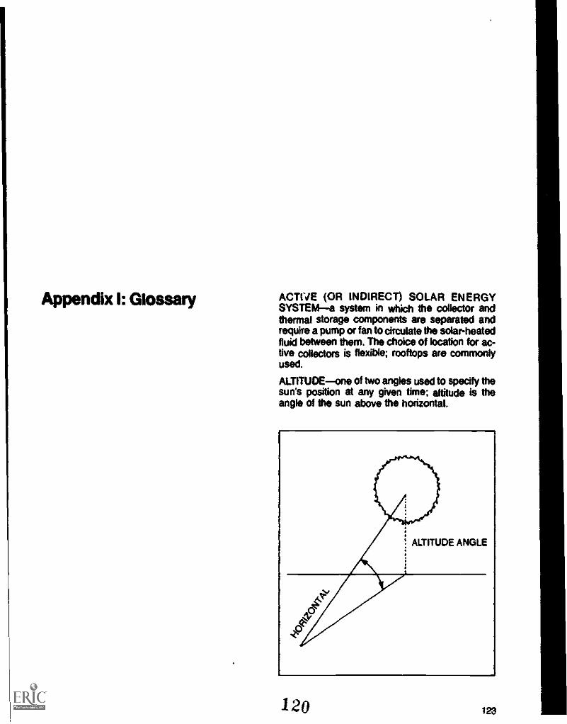
ACTIVE (OR INDIRECT) SOLAR ENERGYSYSTEMa system in which the collector andthermal storage components are separated andrequire a pump or fan to circulate the solar-heatedfluid between them. The choice of location for ac-tive collectors is flexible; rooftops are commonlyused.
ALTITUDEone of two angles used to specify thesun's position at any given time; altitude is theangle of the sun above the horizontal.
120 123

Appendix I: Glossary
ANGLE OF INCIDENCEthe angle at which di-rect sunlight ablates a surface. The angle of inci-dence affects the amount of energy absorbed by asolar collector. Sunlight with an incident angleclose to 90° (perpendicular to the surface) tendsto be absorbed, while lower angles tend to reflect
COLLECTOR
AZIMUTH (SOLAR)one of two angles used tospecify the sun's position at any given time:azimuth is the angle between south and the pointon the horizon directly below the sun (Anderson,1978). South is CP and angles to the east and westare described as 0' to 180°E or 0' to 180°W.
124
SOUTH
NORTH
BTU OR BRITISH THERMAL UNITthe quan-tity of heat required to raise one pound of waterone degree F.
BUILDING ORIENTATIONthe relationship of abuilding to south. A building's orientation isspecified by the direction of its longest ads.
121

COLD NIGHT SKYthe low effective tempera-ture of the sky on a clear night. Most of the heatradiated from a body outdoors is given off to thecold night sky. This process is used by radiativenatural cooling systems having roof ponds. Skyaccess for such systems is not crucial, with over80% of radiant heat loss occurring to the sky 307above the horizon.
COLLECTORany device or area that uses thesun's energy to heat domestic water or to heat,COOL or light a living space. This broad definitionincludes not only familiar space and domesticwater heating system collectors but also collec-tors for space cooling.
COLLECTOR EFFICIENCY the percentage ofsunlight reaching the collector surface thatcan beextracted as useful energy (Anderson, 1976).
COOL NORTH SKYthe area of north sky withrelatively low temperature on clear days. Heat canbe dissipated during the day from a surfaceshaded -from the sun and facing north. This ismade possible by the cool spot in the sky that oc-curs at the point opposite from and at a right angleto the sun. Averaged over the day, the coolestspot is due north at an angle of elevation from thehorizon equal to Er minus the altitude of the sunat noon. This can be an effective method fornatural cooling using shaded roof pond systems.
LE.13Daytime heat dissipation to the cool north sky.
DIFFUSE SUNLIGHTsunlight that reaches theearth after being reflected off atmospheric parti-cles. On a cloudy day, diffuse light may accountfor all the sunlight received at the surface. Diffusesunlight comes along no set path; it generallycomes from the entire skyvault, the most comingfrom the area of the sky near the sun.
DIRECT SOLAR ENERGY SYSTEMsee Pas-sive Solar Energy Systems.
DIRECT SUNLIGHTsunlight that comesstraight from the sun. Skyspace angles and mostsolar planning guidelines are based on direct sun-light. Direct sunlight has higher intensity than dif-fused sunlight.
DISSIPATORany device used to dissipate or re-ject heat in natural cooling systems. Dissipatorstypically work by radiation, evaporation, or con-duction. They range from operable windows usedfor night ventilation to more complex roof ponds.
EASEMENTa form of private agreement withthe potential to protect solar access. Easementsare interests in property, which can be bought andsold like property itself. A common example is theutility easement.
ENERGY SHARINGcollecting solar energy onone building or portion of a building and distribut-ing it to other areas which have pow solar access.
122126

qppendbc 1: Glossary
EVAPORATIVE COOLINGcooling provided bythe evaporation of water. Evaporative coolinguses water's ability to absorb and store heat in theevaporative process, cooling itself and the envi-ronment in contact with it. This process is most ef-fective during daytime hours; therefore most sys-tems using this principle require integral shadingdevices.
INDIRECT SOLAR ENERGY SYSTEMSseeActive Solar Energy Systems.
LOCAL SOLAR TIME (LOCAL APPARENTSOLAR TIME)--time measured by the actual lo-cation of the sun. For example, noon occurs whenthe sun aligns with the north/south axis of theearth.
M1CROCUMATEthe climate of a specific site orportion of a site. Microdimates result from theoverall regional climate as it is affected by localsite conditions, including ground slope and orien-tation, topographic features, elevation, vegeta-tion. winds, water bodies, ground surface, andbuildings. These microdimatic influences affectboth the heating and cooling requirements ofhouses and their potential for solar access.
NATURAL COOLINGspace cooling aftemativesto energy-consumptive central air-conditioningsystems. The five principal means of natural cool-ing are: shading, ventilation, conduction control,radiation, and evaporation.
126
NORTH PROJECTIONthe length of an object'sshadow pattern measured along the north/southgods.
THESE DISTANCES ARE THE NORTHPROJECTION OF THE BUILDING SHADOW.
123

ORIENTATIONthe position of an object with re-spect to true compass points. (See BuildingOrientation.)
PASSIVE (OR DIRECT) SOLAR ENERGYSYSTEMa system where the collector andthermal storage components are integrated, re-quiring no transfer device for solar-heated fluid. Apassive systems tends to have less hardwarethan an active system; it is usually built as an es-sential component of the building rather than asan addition.
PLANNED UNIT DEVELOPMENT (PUD)a de-velopment planned as a whole, where conven-tional subdivision regulations (such as type ofhousing, height limitations, setbacks, densities,and minimum lot sizes) are waived to allow moredesign flexibility and amenities. This kind of de-velopment has greater potential for solar accessplanning than does conventional development
Appendix I: Glossary
RADIATIVE COOLINGcooling provided bywarm surfaces radiating excess heat to cool sur-faces. Water bodies (roof ponds) and massiveconstruction materials (concrete and stone) ab-sorb heat from interior spaces during daytimehours and radiate it away at night (See Cold NightSky and Cool North Sky).
RESTRICTIVE COVENANTSthe most com-mon form of private agreement that can be usedto protect solar access; a restrictive covenant is acontract between two or more people which in-volves mutual promises of reciprocal benefits andburdens among the contracting landowners.
SKYSPACE that portion of the sky which mustremain unobstructed for a collector to operate ef-fectively. Protecting solar access simply meanslocating objects, such as buildings and trees,where they will not shade a collector's skyspace.Skyspace is specified by using latitude-dependentskyspace angles, which give the sun's position atcritical times. Skyspace requirements vary withlatitude and the use pattern of the collector.
SKYSPACEBOUNDARIES
"Skyspace"that portion of the sky which mustremain unobstructed for a collector to operateeffectively.
1 PJ 127

Appendix I: Glossary
SOLAR ACCESSallowing sunlight to strike asolar collector. This is accomplished by locatingobstructions, such as buildings and trees, wheretheir shadows will not fall on a collector during crit-ical periods of operation. The concept of skyspacedefines that portion of the sky which must remainunobstructed and defines specified critical anglesfor use in solar planning.
SOLAR ANGLESangles used to specify thesun's position at a given time. (See Altitude andAzimuth.)
SUN TEMPEREDa building whose long wallsand mayor glazing surfaces are oriented to thesouth. This maximizes beneficial sunlight warm-ing the building in winter. Overhangs or shadingdevices shade glazing to minimize unwantedheat gain in summer. Solar tempering can beused to advantage in almost all climates.
SURFACE-TO-VOLUME RATIOthe ratio of ex-posed surface of a building to occupied volume. Ameasure of exposure to harsh climate conditionscausing unwanted heat loss and heat gain.(Lower numbers are desirable). This ratio is espe-daily useful in evaluating alternative buildingforms.
THERMAL MASSany material used to store thesun's heat or the night's coolness. Water, con-crete, and rock are common choices for thermalmass. In winter, thermal mass stores solar energycollected during the day and releases it duringsunless periods (nights or cloudy days). In sum-mer, thermal mass absorbs excess daytime heatand ventilation allows it to be discharged to theoutdoors at night.
THERMOSIPHONa method of circulating afluid in which the warmer, less dense portion risesabove the cooler. This method can be used inplace of pumps to transfer solar-heated water orair.
USE PATTERNthe use pattern of the solarenergy system refers to the time when the systemis needed. The daily use pattern for residences isboth day and night, while offices and schools maybe used only during daytime hours. The yearlyuse pattern, is related to the function of the solarenergy system; for example, space heating isused only during the cold season, while domesticwater heating is used all year. The use patternlargely determines the skyspace requirements ofthe solar energy system.
128 ...t
125

Appendix II: SkyspaceAngles
The recommended 45-degree solar skyspaceazimuths are suitable for latitudes up to 40 de-grees north. Beyond that, the solar altitudes at thewinter solstice (December 21) are too restrictive atthe am. and p.m. azimuth angles. At 45 degreesnorth latitude, for example, the a.m. and p.m.solar altitude is 4.4 degrees; at 48 degrees northlatitude, the sun is only 2.4 degrees above thehorizon at the a.m. and p.m. hours. These lowsolar altitudes are clearly unsuitable for tworeasons: first, solar radiation below 12 degrees al-titude is reduced in intensity because the atmos-phere itself absorbs radiation before it strikes thecollector and second, shadow lengths at the sol-stice at that latitude would be so great that de-velopment on lots to the south of the collectorwould be unduly restricted.
To define solar azimuths for the higher latitudes,a solar skyspace of 50-degree azimuths for thea.m. and p.m. angles is suggested. At winter sol-stice, the sun will be more than 12 degreesabove the horizon only at azimuths plus or minus38 degrees (for 45 degrees north latitude) and 32degrees (for 48 degrees north latitude). As thesun rises higher in the sky in the fall and springmonths, however, the wider skyspace anglesallow more solar radiation to fall on the collectorat times other than around the winter solstice, asthe sun's path across the sky describes an arclying above the critical 12-degree altitude forlonger periods of time. This wider skyspace defi-nition would allow usable solar radiation in thespring and fall months, which still have appreci-able solar heating requirements as a result of thecooler, northern climate. The site planner, how-ever, must remember that adopting a solar sky-space definition using 50-degree azimuths for thea.m. and p.m. hours allows increased solar ac-cess during the entire heating season at thesehigher latitudes.
If the topography, density, or latitude of a com-munity make a winter solstice period too restric-tive, other standards can be adopted. Another im-portant factor is tree foliage. Obviously, a tree withfew or no leaves in winter may be full of leaves inthe middle of summer. This factor has to be takeninto account in using the winter solstice to deter-mine skyspace.
1 or 4 olt%

Appendix II.: Skyspace Angles
As mentioned earlier, some uses of solarenergy do not require that the solar skyspace bebased on winter conditions. A solar collector for acooling system that is used only in the warmermonths can have a completely different skyspacerequirement than a system used for winter heat-ing. For example, because of the higher collectortemperatures needed to evaporate the coolant,cooling systems using absorption coolingmechanisms require a much wider solar skyspacethan the 45-degree skyspace defined for winterheating. In that the sun is higher in the sky duringthe summer months, there is a longer period oftime during the day when solar radiation is availa-ble to the collector. The longer time period when
the sun is above the critical 12-degree altitude re-sults in a skyspace that is defined by much largerazimuths than the 45-degree boundaries of thewinter .skyspace. Similarly, solar cooling systemsusing radiation or evaporation as coolingmechanisms may require solar access that en-compasses the cool north sky or the entire coolnight sky. However defined, this access, if un-obstructed, permits the maximum practicalamount of sunlight to reach the solar collectorover the course of the required period of use.
Figure 106 gives recommended skyspaceazimuths and their corresponding altitudes for dif-ferent latitudes, with the percentages of dailyradiation yielded by using those angles.
Figure 106. Recommended Skyspace Angles for December 21
N. LatitudeAM/PM Position"
Azimuth Altitude Noon AltitudePircentF..diation"""
25° 45° 25° 42° 76%
30° 45° 20° 37° 80%
35° 45° 16° 32° 85%
40° 45° 12° 27° 90%
45°" (50°) (12°) 22° 88%
486" (50°) (121 18° 87%
The AM1PM angles presented in this chart are the same for both east of south and west of south.For example, if the skyspace azimuth is 50°, then the protected area goes from 50° east of south to50° west of south.
"The 50° azimuths are not based on December 21st, but are suggested as a compromise to assuresolar access during the entire heating season exclusive of the winter solstice period. Similarly, the 12degree altitudes apply only to those months when the sun's path is 12 degrees above the horizonwithin the 50 degree azimuth angles.
'"Radiation is based on the percentage of total available radiation falling on a horizontal surface onDecember 21. Example:, If the skyspace between 45° east of south and 45° west of south isprotected at 30° latitude, then 80% of the available radiation will strike the collector. If the collector istilted, then these percentages may be even higher.
127Inn

Appendix II: S
kyspace Angles
1
Figure 107. T
able of Hourly A
ltitude, Azim
uth, and Percent of A
vailable Radiation
This table show
s hourly values at varying latitudes for solar altitude, azimuth, and percent radiation falling
on Decem
ber 21. The percent radiation value is the portion of daily solar radiation falling in the hour-long
time period one-half hour before and after the tim
e given on the table. For exam
ple, for the 2:00 column,
it is the percent radiation falling from 1:30 until 2:30. T
he sum of the hourly values equalsapproxim
ately100 percent. T
his value gives an idea of how m
uchenergy a solar collector w
ill be deprived of if shadedduring a given tim
e of day.
Tim
e of Day
89
1011
121
23
4A
lt14.3
24.833.5
39.441.6
39.433.5
24.814.3
N25°
Az
-55.1-45.6
-33.4-17.9
0.017.9
33.445.6
55.10
% R
ad8.7
11.011.9
12.312.4
12.311.9
11.08.7
rA
lt11.4
21.329.3
34.636.6
34.629.3
21.3114
t30°
Az
- 54.2-44.1
-31.7-16.8
0.016.8
31.744.1
542h
% R
ad7.9
11.012.1
12.612.8
12.612.1
11.07.9
Aft
8.517.7
25.029.9
31.629.9
25.017.7
8.5I_
35°A
z-53.5
-42.9-30.4
-15.90.0
15.930.4
42.953.5
a%
Rad
6.711.0
12.513.2
13.3132
12.511.0
6.7t
Alt
5.514.0
20.725.0
26.625.0
20.714.0
5.5i
40°A
z- 53.0
- 42.0- 29.4
-15.20.0
15.229.4
42.053.0
t%
Rad
4.511.0
13.214.1
14.414.1
13211.0
4.5u
Alt
2.5102
16.320.2
21.620.2
16.310.2
2.5d
45°A
z- 52.7
-41.2- 28.5
-14.70.0
14.728.5
41252.7
e%
Rad
1.010.7
14.415.8
16.215.8
14.410.7
1.0A
lt.6
8.013.7
17.318.6
17.313.7
8.0.6
48°A
z-52.6
-40.9-28.2
-14.40.0
14.428.2
20.952.6
% R
ad0.0
9.714.8
16.817.3
16.814.8
9.70.0
131

Appendix Ill: Shadow LengthTables and Equation
25° NORTH LATITUDE
SLOPE AM
N
NOON PM AM
NENOON PM AM
0% 2.1 1.1 2.1 2.1 1.1 2.1 2.1
5% 2.3 1.2 2.3 2.1 1.2 2.4 2.010% 2.5 1.3 2.5 2.1 1.2 2.7 1.8
15% 2.7 1.4 2.7 2.1 1.3 3.1 1.7
20% 3.0 1.5 3.0 2.1 1.4 3.6 1.6
30° NORTH LATITUDE
These tables give the shadow length on December21 of a one -foot pole for varying latitudes and di-rections and degrees of slopes. The a.m. and p.m.values correspond to 45 degree azimuths that areused to define the day's period of usable solarradiation. The figures are rounded off, and theremay be some errors in shadow length for steeperslopes or taller buildings at 45 degrees and 48 de-grees north latitude, where the rounding-off errormay be multiplied extensively.
Figure 108. Shadow Length Tables
E
NOON Pie
SEAM NOON PM
S
AM NOON Pie AM
SWNOON PM
WAM NOON PM AM
NWNOON PM
1.1 2.1 2.1 1.1 2.1 2.1 1.1 2.1 2.1 1.1 2.1 2.1 1.1 2.1 2.1 1.1 2.1
1.1 2.3 1.9 1.1 2.1 2.0 1.1 2.0 2.1 1.1 1.9 2.3 1.1 2.0 2.4 1.2 2.1
1.1 2.5 1.7 1.0 2.1 1.8 1.0 1.8 2.1 1.0 1.7 2.5 1.1 1.8 2.7 1.2 2.1
1 1 2.7 1.6 1.0 2.1 1.7 1.0 1.7 2.1 1.0 1.6 2.7 1.1 1.7 3.1 1.3 2.1
1.2 3 0 1.5 1.0 2.1 1.6 0.9 1.6 2.1 1.0 1.5 3.0 1.2 1.6 3.6 1.4 2.1
SLOPE AM
N
NOON PM AM
NE
NOON PM AM
E
NOON PM AM
SENOON PM AM
SNOON PM AM
SWNOON PM AM
WNOON PM
14W
AM NOON PM
0% 2.7 1.3 2.7 2.7 1.3 2 7 2.7 1.3 2.7 2.7 1.3 2.7 2.7 1.3 2.7 2.: 1.3 2.7 2.7 1.3 2.7 2.7 1.3 2.75% 2.9 1.4 2.9 2.7 1.4 3.1 2.4 1.4 2.9 2.4 1.3 2.7 2.4 1.3 2.4 2.7 1.3 2.4 2.9 1.4 2.4 3.1 1.4 2.7
10% 3.3 1.6 3.3 2.7 1.5 3.6 2.2 1.4 3.3 2.1 1.2 2.7 2.2 1.2 2.2 2.7 1.2 2.1 3.3 1.4 2.2 3.6 1.5 2.715% 3.7 1.7 3.7 2.7 1.6 4.4 2.1 1.4 3.7 1.9 1.2 2.7 2.1 1.1 2.1 2.7 1.2 1.9 3.7 1.4 2.1 4.4 1.6 2.720% 4.3 1.9 4.3 2.7 1.7 5.7 1.9 1.4 4.3 1.7 1.2 2.7 1.9 1.1 1.9 2.7 1.2 1.7 4.3 1.4 1.9 5.7 1.7 2.7
.1 29132

35 NORTH LATITUDEN NE E
SLOPE AM NOON PM AM NOON PM AM NOON PM
0% 3.5 1.6 35 3.5 A 3.5 3.5 15 3.55% 4.0 1.8 4.0 3.5 1.7 4.2 3.1 1.6 4.0
10% 4.6 2.0 4.6 3.5 1.8 5.3 2.8 1.6 4.615% 5.5 2.2 5.5 3.5 2.0 7.2 2.5 1.6 5.520% 6.8 2.5 6.8 3.5 2.2 11.4 23 1.7 6.8
SEAM NOON PM AM
SNOON PM
3.5 1.6 35 35 1.6 3.53.0 1.5 3.5 11 1.5 3.12.6 1.5 3.5 2.8 1.4 2.82.3 1.4 .3.5 2.5 1.3 252.0 1.3 3.5 2.3 1.3 2.3
Appendix 111:Shadow Length Tabtes and Equation
SWAM NOON PM
3.5 1.6 3.53.5 1.5 3.03.5 1.5 2.615 1.4 2.33.5 1.3 2.0
40° NORTH LATITUDEN NE E SE S
SLOPE AM NOON PM AM t4OON PM AM NOON PM AM NOON PM AM NOON PM
0"4 4.8 2.0 4.8 4.8 2.0 4.8 4.8 2.0 4.8 4.8 2.0 4.8 4.8 2.0 4.85% 5.7 2.2 5.7 4.8 2.2 6.2 4.1 2.0 5.7 3.8 1.9 4.8 4.1 1.$ 4,1
10% 7.2 2.5 7.2 4.8 23 9.1 3.6 2.0 7.2 32 1.8 4.8 3.6 1.7 3.615% 9.6 2.9 9.6 4.8 2.6 16.6 3.2 2.0 9.1 2.8 1.7 4.8 3.2 1k 3.220% 14.5 3.4 14.5 4.8 2.8 97.5 2.8 2.0 145 24 1.6 4.8 2.8 1.5 2.8
AM
WNOON PM AM NOON
NWPM
3 5 1.6 3.5 35 1.6 154,3 4.2 1.7 3.54.6 1.6 2.8 5.3 1.8 3.55.5 1.6 2.5 7.2 2.0 3.56.8 1.7 23 11.4 22 3.5
SWAM NOON PM
4.8 2.0 4.8
WAM NOON PM
4.8 2.0 4A
NWAM NOON PM
4.8 2.0 4.84.84.8 1.9 3.8 5.7 2.0 4.1 6.2 224,94.8 IA 32 7.2 2.0 3$ 9.1 2.34,84.8 1.7 2.8 9.6 2.0 3.2 16.6 2.6
2.8 4.84.8 1.6 2.4 14.5 2.0 2.8 97.5
480 NORTH LATITUDEN NE E SE s SW W NW
Koes AM Noom Pm AN NOON PM AM NOON Pm AM NOON PM AM NOON PM AM NOON PM AM NOON PM AM NOON PM
0% 7.2 2.5 72 7.2 2.5 7.2 72 2.5 7.2 7.2 2.5 7.2 7.2 2.5 72 7.2 2.5 7.2 7.2 25 7.2 7.2 2.5 725% 9.6 2.9 9.6 7.2 2A 11.2 5.7 2.5 9.6 5.3 2.3 7.2 5.7 2.2 5.7 7.2 23 5.3 9.6 25 5.7 11.2 2.8 7.2
10% 14.6 3.4 14.6 7.2 3.1 25.6 4.8 2.5 14.6 4.2 2.2 72 4.8 2.0 4.8 72 2.2 42 140 2.5 4.9 25.6 3.1 7215% 30.3 4.1 30.3 7.2 3.5 - 4.1 2.6 30.3 3.5 2.0 7.2 4.1 1.9 4,1 72 2.0 3.5 303 2.6 4.1 - 3.5 7220% - 5.2 - 7.2 4.0 - 3.6 2.6 - 2.9 1.9 7.2 3.6 1.7 3.6 7.2 1.9 2.9 - 2.6 3.6 - 4.0 7.2
48° NORTH LATITUDEN NE E SE s SW W NW
%on Au NOON OM AM NOON PM AM NOON PM AM NOON PM AM NOON PM AM NOON Pm AM NOON PM AM NOON PM
0% 10.1 3.0 10.1 10.1 3.3 10.1 10.1 3.0 10.1 10.1 3.0 10.1 10.1 3.0 10.1 10.1 3.0 10.1 10.1 3.0 10.1 10.1 3.0 10.15% 15.8 3.5 15.8 10.1 3.3 20.5 7.5 3.0 15.8 6.7 2.7 10.1 7.5 2.6 7.5 10.1 2.7 6.7 15.8 3.0 7.5 20.5 3.3 10.1
10% 35.7 43 35.7 10.1 3.8 - 5.9 3.0 35.7 5.0 2.5 10.1 5.9 5.0 35.7 3.0 5.9 - 3.8 10.115% .- 5.4 - 10.1 4.4 - 4.9 3.0 - 4.0 2.3 10.1 4.9 2.1 4.9 10.1 2.3 4.0 - 3.0 4.9 - 4.4 10.120% - 7.5 - 10.1 5.2 - 42 3.0 - 3.3 2.1 10.1 42 1.9 4.2 10.1 2.1 3.3 - 3.0 4.2 -
VIA2 '1 .

,
Appendix III:Shadow Length Tables and Equation
Figure 109. Calculation of Slope Percentage
FI vertical distance _ V SLOPE (%)horizontal distance H
PROBLEM - TO FIND SLOPE OF ABH = 500'STEP 1:ESTABLISHHORIZONTALDISTANCEr
1 i
. . , . = I 11 r . I 1
AB = 1/2-since scale is 1" - 1000'them,1 h x 1000 500AB = 500'
V = 20'STEP 2:ESTABLISHVERTICAL DISTANCE
Since vertical distanceequals the differencebetween contours, andsince contour interval onthis map is 20 feet,then: A - B =740' - 720' .-- 20'
It __.20 = 04H 500'
=In." SLOPE AB -= 4°/0Source: The Land Book Office of Comprehensive Planning. N.H., 1976
Calculating Shadow PatternsShadow patterns may be calculated graphically byformula or by using the shadow length tables. Ineither case, various shadow lengths for each timeof day are laid out on paper and connected to formthe final pattern. Below is an example of how to de-velop a shadow pattern using the shadow lengthtables in the Appendix.
The example shows how the shadow pattern of apole is calculated. The pole is used because it isthe simplest ground-anchored object that can casta shadow. More complex objects such as trees orhouses can be represented by a composite ofpoles to calculate their shadow patterns.
134
Calculating the shadow Pattern of a Pole
Pole is 30 feet high.
Latitude of location is 40 degrees north.
Pole is on land that slopes to the southeast ata 10 lercent grade.
Step 1: From the appropriate table (in this casethe 40-degree table) find the shadowlength values for a.m., p.m., and noon.
Read the intersection of the columnslabeled "S.E." and "10 percent," as in-dicated on the chart.
131

Appendix Ill:Shadow Length Tables and Equation
40° NORTH LATITUDE
SLOPE
NAM NOON Pm
NE
AM NOON PM
E
AAA NOON PM
SEmA NOON PM mA NOON PM
0% 4.8 2.0 4.8 4.8 2.0 4.8 4.8 2.0 4.8 4.8 2.0 4.8 4.8 2.0 4.85% 5.7 2.2 5.7 4.8 2.2 6.2 4.1 2.0 5.7 3.8 1.9 4.8 4.1 1.8 4.1
10% 7.2 2.5 7.2 4.8 2.3 9.1 3.6 2.0 7.2 3.2 1.8 4.8 3.6 1.7 3.615% 9.6 2.9 9.6 4.8 2.6 16.6 3.2 2.0 9.1 2.8 1.7 4.8 3.2 1.6 3.220% 14.5 3.4 14.5 4.8 2.8 97.5 2.8 2.0 14.5 2.4 1.6 4.8 2.8 1.5 2.8
Step 2: The values given in the table are for aone-foot pole, so they must be multi-plied by the height of the pole, in thiscase 30 feet.
a.m. value3.2
noon value1.8
p.m. value4.8
x pole height30
x pole height30
x pole 'height30
= a.m. shadow length96 feet
= noon length54 feet
= p.m. length144 feet
Step 3: Scale the shadow lengths out on paperas viewed from overhead and connectthe end points.
45° boundaries of skyspace are used to definearea of shadow that will block important sunlight.
The resulting figure approximates the completeshadow pattern, which, if perfectly plotted, wouldresult in a curve opposite the right angle. If a pat-tern closer to the true one is desired, additionalshadow lengths for other times of the day can bedrawn in to fill out the curve.
132

Appendix Ill:Shadow Length Tables and Equation
Determining the Shadow Pattern for a &aiding or mine the pattern for a single pole, by treating awee building or tree as a number of poles, as picturedThe shadow pattern for a building or tree can be belowdetermined in much the same way used to deter-
Figure 110. Representing a Building or Tree as Poles
Keep in mind that trees have depth, the same the tree crown "centerline." Trees with variousas buildings. For maximum accuracy, therefore, common shapes also can be represented byadditional poles should be located to the north of poles of varying heights.
Figure lit. Representing Common Tree Shapes as Poles
133

The shadow lengths for each pole at the criticaltimes of day are laid out and the composite yieldsthe pattern for the building or tree. The followingexample shows how this is done fora building andtree simultaneously:
Building is 9' high at eaves and 12' high atPeak.
Tree is 40' high and 30' wide.
Latitude of location is 35* north.
Land slopes to southwest at 15 percentgrade.
Step 1: Draw an overhead plan of the buildingand tree using a series of poles.
Step 2: From the appropriate table, in this casefor 35 degrees, find the shadow lengthvalues for a.m., noon, and p.m. Theyare:
a.m.-2.3 noon-1.4 p.m...3.5Multiply the ratios times the height ofthe poles used in the building and treeexamples.
Heightof
Pole
Shadow Length
A.M. Noon PM.
Building 9' 21' 13' 32'12' 28' 17' 42'
Tree 40' 92' 56' 140'
oft
Appendix III:Shadow Length Tables and Equation
...........
ii 40' 40' 40'0 0 0.. I.. ..
301
Step 3: Scale the shadow lengths out on theoverhead views of the buildings andtree. The boundaries of the skyspacein this case are 45 degrees, so the a.m.and p.m. shadow lengths are laid out at45 degrees east and west of north. (Ina situation where another skyspaceangle is used, say 50 degrees, thisangle should be used in the shadowpattern.) Finally, connect the end pointsof the shadow lines for the shadowpattern.

Appendix M:Shadow Leap Tables and Eon
. . /. /./ / ///
1 ." Z.
BUILDING TREE
ENLARGED BUILDING SHADOW ENLARGED TREE SHADOW
i 3.g

Shadow Length FormulasWhile the shadow length charts are useful in mostsituations, they are slightly inaccurate as a resultof "roundinc or errors. But what about a com-munity that does not lie directly on an exactlatitude shown in the chart, or a site that lies on asouth by southeast slope or on a gradient of 12percent, none of which are shown on the shadowlength charts? The following shadow length equa-tions increase the accuracy of the charts, so thatplanners can develop precise data for local cir-cumstances. For communities where such a highdegree of accuracy is not warranted, the approxi-mations shown in the shadow length chartsshould be suflicient. To achieve maximum accu-racy, however, it Is necessary to know the exactlatitude and the exact solar altitude and azimuthsat that latitude. These can be gathered from aNautical Almanac or from the ASHRAE Hand-book of Fundamentals, published by the Ameri-can Society of Heating, Refrigeration and AirConditioning Engineers.
The following abbreviations are used in theequations:
/41 = solar altitudeAs = solar azimuthH = height of object casting shadowS = true shadow length (as shown in cross-
section in figure 112, belowS. = plan projected shadow length (the
shadow length as shown in a plan viewof an object and its shadow: It presumesa distance measured on a hypotheticallevel surface, instead of the varying ir-regularities of an actual site as shown infigure 112).
Si = slope angle, as described in figure 112.
Appendix Ill:Shadow Length Tables and Equation
= slope percent/100.For the simple condition of shadows on a level
surface or zero percent slope, the shadow lengthis given by the formula:
(1) S = Man (Ai)The shadow falls in a direction exactly opposite
the numerical direction of the sun:(2) k shadow = k sun ± 180'
On a sloping surface the shadow length calcula-tion becomes more nomplex due to the rise or fallof the land. If the land rises in the same directionas the direction of the sun's rays, the shadow willbe shortened: if the land falls away, the shadowwill be lengthened.
This fact may be expressed mathematically as:(3) Fellation, = S. x tan (Al)(4) Rise.,,, = S. x tan (Ss)
= 5, xThe rise of the land and the fall of the shadow
equal the height of the shading object.(5) H = fall = rise
= 5, x [tan (A) + ran (Salor
(6) H = S. x [tan (Al) +Thus, the plan projected shadow length is:
H(7) Sy =
Ilan (A.) + SalBut the slope of the land does not usually lie in
the direction of the sun's rays. lb account for theangle between the sun's rays and the slope of theland, Equation 7 is modified as follows:
(8) SyUm (Al) + (S x cos (Ai w))
Appendix IV: DeterminingDensity
140
Providing solar collectors with unobstructed ac-cess to sunlight can affect the density of a de-velopment. Buildings can be sited dose to oneanother only to the extent that they do not castshadows across each other's collector surfaces.This limitation on siting can influence the spacingbetween structures and the density of the entireproject. This angle shows how this spacing can bedetermined.
Solar access and development density can bereconciled in two ways. First, developers can pro-ject density based on local regulations and ar-range the development so that shading isminimized. This may mean that some solar ac-cess objectivessouth-wall protection, forexampleare unachievable for some lots if con-ventional lot layout is used. A developer may haveto settle for a less optimal level of solar access insome areas of the developmentsouth-roofprotection, for example, instead of south-wall ac-cess. Second, the developer can consider solaraccess as a major development objective and de-sign the project to increase solar access for alllots. This means that the developer essentiallyworks backwards, establishing a solar access ob-jective and then tailoring the project to meet thisobjective and deriving a project density in the pro-cess. in many cases, however, the density that re-sults from trying to achieve a solar access objec-tive may exceed the density permitted under zon-ing regulations.
Three development conditions can arise insolar access design. The first condition occurswhen south-wall access is the major developmentobjective and a development is designed to pro-vide this level of access to all lots. The density ofsuch a development can be determined by usingthe concept of north shadow projection, discussedearlier in Preliminary Site Planning.
The second condition arises when only roof ac-cess alone is considered. A similar analytical pro-cess is used for roof access as is used for south-wall access, except that the north shadow projec-tion must be drawn in cross-section to evaluatepotential conflicts.
Finally, developments considering either south-wall or south-roof access can be sited on terrainthat slopes to the east and west. In determiningdensity in these cases, the technique of develop-ing shadow patterns (based on shadow lengthdata) is most appropriate.
The three development conditions and thethree different techniques for determining densityare discussed below.
137
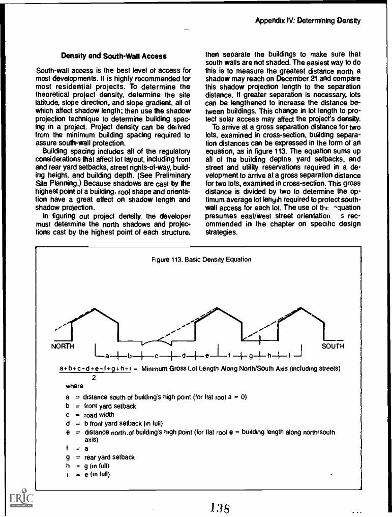
Density and SouthWall Access
South-wall access is the best level of access formost developments. It is highly recommended formost residential projects. To determine thetheoretical project density, determine the sitelatitude, slope direction, and slope gradient, all ofwhich affect shadow length; then use the shadowprojection technique to determine building spac-ing in a project. Project density can be derivedfrom the minimum building spacing required toassure south-wall protection.
Building spacing includes all of the regulatoryconsiderations that affect lot layout, including frontand rear yard setbacks, street rights-of-way, build-ing height, and building depth. (See PreliminarySite Planning.) Because shadows are cast by thehighest point of a building, roof shape and orienta-tion have a great effect on shadow length andshadow projection.
In figuring out project density, the developermust determine the north shadows and projec-tions cast by the highest point of each structure,
Appendix IV: Determining Density
then separate the buildings to make sure thatsouth walls are not shaded. The easiest way to dothis is to measure the greatest distance north ashadow may reach on December 21 and comparethis shadow projection length to the separationdistance. If greater separation is necessary, lotscan be lengthened to increase the distance be-tween buildings. This change in lot length to pro-tect solar access may affect the project's density.
To arrive at a gross separation distance for twolots, examined in cross-section, building separa-tion distances can be expressed in the form of anequation, as in figure 113. The equation sums upall of the building depths, yard setbacks, andstreet and utility reservations required in a de-velopment to arrive at a gross separation distancefor two lots, examined in cross-section. This grossdistance is divided by two to determine the op-timum average lot length required to protect south-wall access for each lot. The use of flu nquationpresumes east/west street orientation. s rec-ommended in the chapter on specific designstrategies.
Figure 113. Basic Density Equation
NORTH SOUTHLa---b } d- -1 f -4- g-1a+ b+ c 4-d+ e-* f 9+ h+ = Minimum Gross Lot Length Along North/South Axis (including streets)
2where
abcde
gh
= distance south of building's high point (for flat roof a = 0)= front yard setback= road width= b front yard setback (in full)= distance north. of building's high point (for flat roof e = building length along north/south
axis)= a= rear yard setback= g (in full)
e (in full)
38

Appendix IV: Determining Density
To use the basic density equation for south-lotaccess, the north shadow projection for eachdwelling must also be used. Where the buildingspacing exceeds the north shadow projection dis-tance, south-wall access can be protected. Butwhen the separation distance is less than thenorth shadow projection, the building spacingmust be increased by lengthening the lot in thecross-section analysis. The lot length must be in-creased by the distance that the north shadowprojection exceeds the building separation its-tame, allowing the developer to substitute northshadow projection for one or more of the variablesexamined in the basic density equation. By mak-ing this substitution, the total lot length is also in-creased by this same distance.
If the birilding's shadow projection length (L) islonger than either a+b+c+d or f+g+ h, then theshadow projection length must be substituted forthese groups of factors.
Where L is greater than a+b+c+ d, substitute Lfor a+b+c+d in the basic density equation.Where L is greater than f+g+ h, substitute L for
these factors. Finally, when L is greater than botha+ b+c+ d and f+g+ h, then substitute L for bothsets of factors. In this situation, the basic densityequation becomes:
L+e+ L+i2
= minimum average lot length along north/southaxis..
Once the minimum average lot length is deter-mined, then the lot length is multiplied by the lotwidth to get the total lot area (in square feet). Thelot area is then divided into 43,560 square feet(the number of square feet in an acre) to obtainthe density, expressed as lots per acre.
Example 1South-Wall AccessFind building spacing and overall density whileproviding solar access to the south wall.
Latitude 40° N, 10% south slope, 70' lot width.Minimum setbacks, road width, and building sizeshown below.
r
Figure 114. South-Wan Access Example
BUILDING B BUILDING A
NORTH 20 15' 15' 40'
Ratio of building height to shadow length = 2.5(from table).Building A shadow length =4 = 26' (2.5) = 65'Building B shadow length = L9 = 15' (2.5) = 37.5'
a+ b+c+ d = 20' + 20' + 25' + 20' = 85'85' >L
f+g+h = 0'+15'+15' = 30'1.9 > 30'
15' 26'
20' 25' 20' 20' SOUTH
MIN.
Use:
a+b+c+d+e+Le+i = 85'+40'+37.5'+20'2 2
91.2' minimum lot length along N/S axis912' length x 70' width = 6387.5 sq. ft. per lot
43560 sq. ft. per acre6.8 lots per acre
6387.5 sq. ft. per lot
142.139
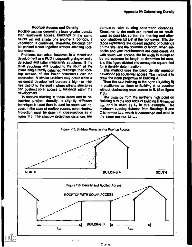
Rooftop Access and DensityRooftop access generally allows greater densitythan south-wall access. Buildings of the sameheight will not shade one another's rooftops, ifvegetation is controlled. Therefore, buildings canbe packed closer together without affecting roof-top access.
Problems can arise, however, in a mixed-usedevelopment or a PUO incorporating single-familydetached and taller multifamily structures. If thetaller structures are located to the south of thelower, single-family detached buildings, then roof-top access of the lower structures can beobstructed. A similar problem may occur when aresidential development borders a high- or mid-rise district to the south, where off-site structurescan obstruct solar access to buildings within thedevelopment.
To analyze shading in these areas and to de-termine project density, a slightly differenttechnique is used than is used for south-wall ac-cess. In the case of rooftop access, north shadowprojection must be drawn in cross-section as infigure 115. The shadow projection distances are
Appendix IV: Determining Density
compared with building separation distances.Structures to the north are moved as far south-ward as possible, so that the morning and after-noon shadows fall just at the roof eaves. This die-tame represents the closest paddng of buildingson the site, and the optimum lot length, when set-backs and yard requirements are considered. Aswith south-wall =OW the lot width is multipliedby the optimum lot length to determine lot area,and this figure divided into acreage in square feetfor a density determination.
This method uses the basic density equationdeveloped for south-wall access. The method is todraw the north projection of Building A.
Then the next building to the north (Building B)is positioned as close to Building A as possiblewithout obstructing solar access to B. (See figure116.)
The distance from the northerly high point onBuilding A to the roof edge of Building B is termedLA and is- used as LA in this example. Theminimum spacing distance from Buildings B andC is termed Len, which is determined and used inthe same manner as I.m.
Figure 115. Shadow Projection for Rooftop Access
..0 .......
NORTH BUILDING A SOUTH
...,'rede--
kg-
Figure 116. Density and Rooftop Access
ROOFTOP WITH SOLAR ACCESS ......-°°-'-.
.0...,...
4.0mrere40'.0re
40°re40'...
L.
..P.'..Me
-11.1 BUILDING B 1.0114
14111
d_
/ ,f n

Appendix IV: Determining Dew's)/
Building B will not shade the roof of Building C. Therefore, only the shadow of Building A will bedrawn.Ratio of shadow length to building height = 4.1 (from figure 54)
L.,, = 40' (4.1) = 164'
137' minimum average lot length along north/south axis 75' width x 137' length =10275'average sq. ft. per lot

Density and East/West SlopesDetermining density where slopes do not runnorth/south requires more detailed graphic work.Since the shadow pattern of a building on a cross
Appendix IV: Determining Density
slope is asymmetrical, building layouts must bedetermined in plan for south-wall access (or inplan and cross-section for rooftop access) beforethe calculations can be made.
Find building spacing and overall density for an east facing slope of 15% latitude 35'N. Provide solar access to thesouth wall of all buildings.Using the method given in Preliminary Site Planning the shadow of a typical building can be.drawn.
Figure 118. Typical Building Dimensions
The following sketch was prepared as the calculations were made.
Figure 119. Topographic Contours
Referring to the Shadow Length Tables in Appendix 111: The AM shadow length for 10' = 28'; for 14' = 35'.The noon shadow length for 10' = 16'; for 14' =-22'.The PM shadow length for 10' = 55'; for 14' .= -- 77'.
Having the shadow pattern for an Individual building, this can be shifted about until a group of buildings and theiraccess road have been laid out. Maximum densities can be achieved by an irregular plan such as that given below
Figure 120. East!West Slope Density Example
)
Once the plan has been "roughed out," densities can be calculated directly as the number of units per acre.For the duster shown the overall area is 225'x140' = 31500 sq. ft.
Average sq. ft. per unit = 31500 = 5250 sq. ft.6
43580 sq. ft./acre = 83 unitslacre5250 sq. ft.Iunit
.

Appendix V: References
IAA
Planning:
American Planning Association. Protecting SolarAccess in New Residential Development: AGuidebook for Planning Officials. Rockville,MD: National Solar Heating and Cooling Infor-mation Center, 1979.A guide to using conventional land-use controlsto protect solar access; includes basic informa-tion on access and model regulations.
American Society of Landscape Architects Foun-dation. Landscape Planning for Energy Con-servation. Reston, VA: Environmental DesignPress, 1977.A guide for planning with vegetation and land-forms. Includes sections on site selection andanalysis and site planning for solar architecture.A number of case studies are given for variousclimatic regions.
County of Sussex. A Design Guide for ResidentialAreas. London, England: Anchor Press, Ltd.,1973.A British study of residential planning. Includesdesign standards for narrow streets andpedestrian walkways; covers a wide variety ofkey planning elements.
De Chiara, J. and L. Koppelman. Urban Planningand Design Criteria. New librk, NY: Van Nos-trend, Reinhold, 1975.A handbook on residential, commercial, indus-trial, and institutional planning standards, em-phasizing conventional planning practice andcontaining little on energy-efficient or solar ac-cess planning.
Manual of Housing Planning and De-sign Criteria. Englewood Cliffs, NJ: Prentice-Hall, 1975.Thi, .tandbook is similar in format and contentto Urban Planning and Design Criteria exceptthat it concentrates on housing and subdivi-sions.
First Passive Solar Home Awards. Rockville, MD:National Solar Heating and Cooling InformationCenter, 1979.Presents the state-of-the-ad designs that wonthe cimpetition sponsored by the U.S. Depart-ment of Housing and Urban Development.
143

Lynch, Kevin. Site Planning. Cambridge, Mk MITPress, 1971.A dassic text on site planning.
Land Design/Research. Cost Effective Site Plan-ning: Single Family Development. Washington,DC: National Association of Home Builders,1976.An introduction to planning compact andenergy-efficient subdivisions.
Living Systems. Davis Energy Conservation Re-port. Winters, CA: Living Systems, 1977.This report describes the Davis Energy Con-servation Project, including the Energy Conser-vation Building Code, planning for energy con-servation, climate analysis, public educationprograms, and solar homes.
National Association of Home Builders. Land De-velopment Manual. Washington, DC: NationalAssociation of Home Builders, 1974.A guide for the housing developer. Solar andenergy-conserving topics are not emphasized,but other basic planning considerations arepresented.
National Solar Heating and Cooling InformationCenter (NSHCIC). A Forum on Solar Access.Rockville, MD: NSHCIC, 1977.A transcript of the proceedings of a forum onsolar access held by the New York State Legis-lative Commission on Energy Systems, in July,1977. Contains an overview of useful informa-tion and opinion on the various legal aspects ofsolar access protection and regulation.
State Solar Legislation. Rockville, MD:NSHCIC, 1979.An overview of state legislation affecting theuse and installation of solar energy equipment.It includes a summary of the relevant statelegislation in existence in January 1979, and isperiodically updated to reflect new laws andstatutes.
Office of Comprehensive Planning. The LandBook. New Hampshire: Office of Comprehen-sive Planning, 1976.A manual prepared for the office of the governorof the state of New Hampshire that is designedto acquaint local officials with the benefits, prin-ciples, and techniques of community land useplanning. There is a strong emphasis on theuse of natural resource information in the plan-ning process.
Appendix V: References
Planning Advisory Service. Caring for the Land.- Planning Advisory Service Report No. 328.
Chicago, IL: American Planning Association,1977.A report published by the American PlanningAssociation on how environmental and naturalresource concerns should be incorporated intothe site planning process for new development.Includes chapters on planning with environmen-tal resources in mind, reviewing developmentproposals, and sources of technical assistance.Explains how to use a natural resource and en-vironmental overlay technique in site planningand reviewing site plans.
Real Estate Research Corporation. The Costs ofSprawl. Stock No. 4111-0021. Washington, DC:Government Printing Office. 1877.A detailed analysis of economic, environmental,social, and direct costs of urban sprawl.
Working Papers on Marketing andMarket Acceptance. Washington, DC: U.S.Department of Housing and Urban Develop-ment, 1978.A two-volume work examining the potentialsand problems of marketing solar homes. Con-tains information on financing, marketing,characteristics of solar purchasers and build-ers, and the impact of lending institutions onconsumers.
Robinette, G. PlantslPeopleland EnvironmentalQuality. Stock No. 2905-0479. Washington, DC:U.S. Government Printing Office, 1972.A graphic prersntation showing how to useplants as environmental planning elements formodifying the impact of wind, solar radiation, airpollution, noise, and visual blight.
Sunset Western Garden Book. Menlo Park, CA:Lane Publishing Co., 1972.An index of ornamental plants and their uses inthe western portion of the United States. Thebook includes maps of the microclimates of theWest, and which plants are best adapted tothem. The maps themselves can serve as val-uable design tools making the book useful forlandscape planning.
Thomas, et al. Overcoming Legal Uncertaintiesabout the Use of Solar Energy Systems.Chicago, IL: American Bar Association, 1978.A booklet that discusses the major legal issueslikely to arise in the use of solar energysystems.
1 £1 4

Appendix V: References
U.S. Department of Commerce. Climatic Areas ofthe United States. Ashville, NC: PublicationsUnit, National Climatic Center, 1974.A compendium of maps and data that illustrateclimatic variations in the United States.
Weiner, Michael. Plant a Tree. New York, NY: Col-lier Books, 1975.A handbook that describes tree species andcharacteristics; includes a guide to planting andmaintaining trees in various climate zones.
Building
Adams, Anthony. Your Energy Efficient Home,Charlotte, VT Garden Way Publishing, 1976.A basic, illustrated introduction to site planningand building density for energy conservation.
American Institute of Architects Research Corpo-ration. Regional Guidelines for Building Pas-sive Energy Conserving Homes. Washington,DC: U.S. Department of Housing and UrbanDevelopment, 1978.A resource book that divides the United Statesinto 13 climatic regions and gives design con-siderations for each.
Solar Dwelling Design Concepts.Washington, DC: U.S. Department of Housingand Urban Development, 1978.An introduction to solar building design with anemphasis on active systems.
Anderson, Bruce. The Solar Home Book. Harris-ville, NH:. Cheshire Books, 1976.A book on direct (i.e. passive) home design andconcepts, giving an introduction to solar hotwater systems.
ASHRAE. Handbook of Fundamentals and Prod-uct Directory. New York, NY: 1972.A standard reference for thermal analysismethodology and detailed intonation on ther-mal properties of materials. Also contains dataon climatic design conditions, solar radiation,and window shading.
Building Research Institute. Solar Effects onBuildings. Publication No. 1607.A compilation of technical articles on solarenergy and buildings. Concentrates on win-dows and skylight design and performance.
Eccli, Eugene. Low Cost Energy Efficient Shelterfor the Owner and Builder. Emmaus, PA:Rodale Kress, 1976:A design manual on energy-efficient homes; in-cludes many sections on windows, doors,vents, and other key house components.
"Energy and the Builderz Proper Site OrientationSaves Energy." Professional Builder, 43, Sep-tember 1978, 83-91.An article giving an overview of siting principlesdeveloped by Professor Wayne Shick of theUniversity of Illinois on how to orient buildings,windows, and overhangs to conserve energy.
Geiger, R. The Climate Near the Ground. Cam-bridge, MA: Harvard University Press, 1975.A detailed scientific text which covers the prin-ciples of microdimatology, mainly in agriculturaland forestry applications.
Givoni, B. Man, Climate, find Architecture. Lon-don, England: Elsevier Publishing Co., 1976.A comprehensive book on human comfort andthermal performance of buildings. Containsquantitative descriptions of the thermal perfor-mances of building materials and design fea-tures, such as ventilation and window shading.
Leckie, et al. Other Homes and Garbage. SanFrancisco, CA: Sierra Club Books, 1975.This book covers a wide variety of informationon self-sufficient residential energy systemssuch as wind, water, solar and methane.
Olgyay, A. and V. Design with Climate. Princeton,NJ: Princeton University Press, 1963.A comprehensive book on climatically adaptedbuilding design and planning.
Solar Control and Shading Devices.Princeton, NJ: Princeton University Press,1957.. -
Similar to Design with Climate but focuses onsolar radiation as a key climatic influence.
Strock, et al. Handbook of Air Conditioning, Heat-ing, and Ventilating. New York, NY: IndustrialPress, Inc. 1976.An engineering manual similar to ASHRAE's.
Sun Angle Calculator. Toledo, OH: Libby-Owens-Ford, 1975.Calculates sun angles and azimuths. The cal-culator covers the United States from 24° northlatitude in 4° increments.
145

Total Environmental Action. Solar Energy HomeDesign in Four Climates. Harrisville, NH:Cheshire Books, 1975.Shows four solar homes that use both activeand passive systems to provide heat, cooling,and domestic hot water.
University of Colorado, Solar ApplicationsLaboratory Heating and Cooing of ResidentialBu icings: Sizing installations and Operating ofSystems. Washington, DC: U.S. Department ofCommerce, 1977.A two-volume set of technical handbooks foruse in training technicians to design, install, andoperate solar heating and cooling systems forresidential buildings.
Wade, A. and N. Ewenstein. 30 Energy EfficientHouses You Can Build. Emmaus, PA: RodalePress, 1977.Contains photographs, drawings, houseplans,and narratives on solar and energy-conservinghomes.
1 4 R
Appendix V: References
*U I. 00uNOWner MMHG °MCI tots f40-01/2704


![SIFL and ENTERTAINMENT COST DISALLOWANCE ... Academy Webinar 1-9-2014.pdfBoeingField] Airplane’s miles traveled = 6,534 Bob’s miles for SIFL = 3,436 (1,718 x 2) SIFL miles are](https://img.pdfslide.us/doc/110x75/5f4680a63e277c73f9073426/sifl-and-entertainment-cost-disallowance-academy-webinar-1-9-2014pdf-boeingfield.jpg)


![AAACS4451J] PER HARI OM MARATHA, JUDICIAL MEMBER …voiceofca.in/siteadmin/document/19_06_12_Case2.pdf · PER HARI OM MARATHA, JUDICIAL MEMBER: ... SIFL vested in the assessee-company](https://img.pdfslide.us/doc/110x75/5b4e154d7f8b9ace388b4784/aaacs4451j-per-hari-om-maratha-judicial-member-per-hari-om-maratha-judicial.jpg)