Embed Size (px)
Citation preview
Wood structures Copyright © G G Schierle, 2001-02 press Esc to end, ↓ for next, ↑ for previous slide 1
Wood structures Copyright © G G Schierle, 2001-02 press Esc to end, ↓ for next, ↑ for previous slide 2
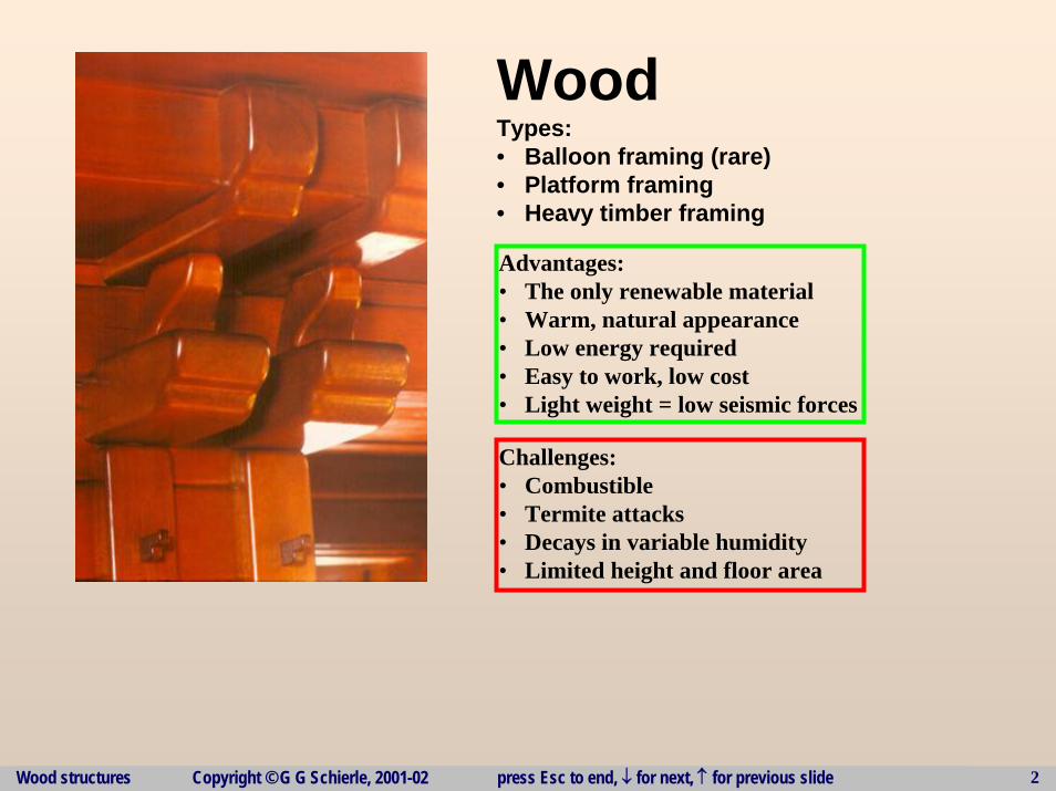
WoodTypes:• Balloon framing (rare)• Platform framing• Heavy timber framing
Challenges:• Combustible• Termite attacks • Decays in variable humidity• Limited height and floor area
Advantages:• The only renewable material• Warm, natural appearance• Low energy required• Easy to work, low cost• Light weight = low seismic forces
Wood structures Copyright © G G Schierle, 2001-02 press Esc to end, ↓ for next, ↑ for previous slide 3
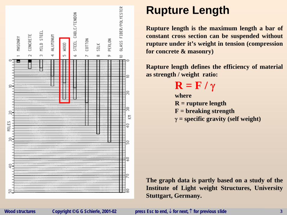
Rupture LengthRupture length is the maximum length a bar of constant cross section can be suspended without rupture under it’s weight in tension (compression for concrete & masonry)
Rapture length defines the efficiency of material as strength / weight ratio:
R = F / γwhereR = rupture lengthF = breaking strengthγ = specific gravity (self weight)
The graph data is partly based on a study of the Institute of Light weight Structures, University Stuttgart, Germany.
Wood structures Copyright © G G Schierle, 2001-02 press Esc to end, ↓ for next, ↑ for previous slide 4
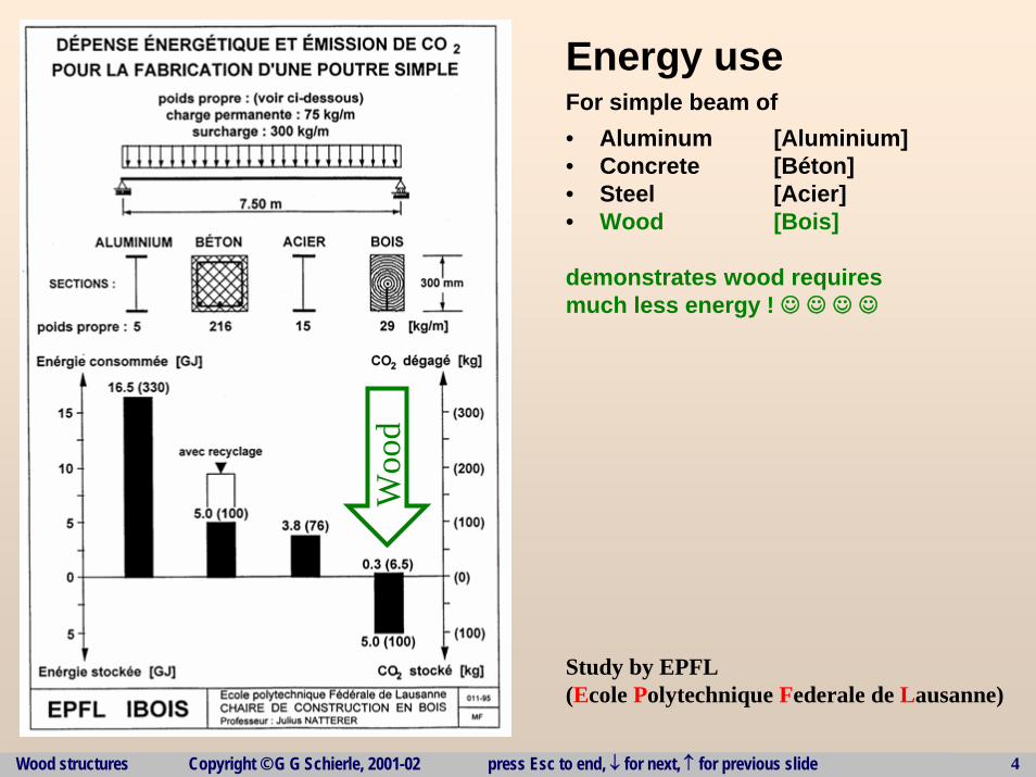
Energy useFor simple beam of• Aluminum [Aluminium]• Concrete [Béton]• Steel [Acier]• Wood [Bois]
demonstrates wood requires much less energy ! ☺ ☺ ☺ ☺
Study by EPFL(Ecole Polytechnique Federale de Lausanne)
Woo
d
Wood structures Copyright © G G Schierle, 2001-02 press Esc to end, ↓ for next, ↑ for previous slide 5
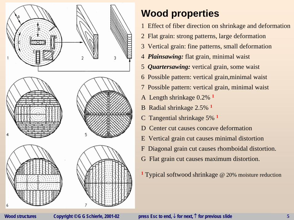
Wood properties1 Effect of fiber direction on shrinkage and deformation2 Flat grain: strong patterns, large deformation3 Vertical grain: fine patterns, small deformation4 Plainsawing: flat grain, minimal waist5 Quartersawing: vertical grain, some waist6 Possible pattern: vertical grain,minimal waist7 Possible pattern: vertical grain, minimal waistA Length shrinkage 0.2% 1
B Radial shrinkage 2.5% 1
C Tangential shrinkage 5% 1
D Center cut causes concave deformationE Vertical grain cut causes minimal distortionF Diagonal grain cut causes rhomboidal distortion.G Flat grain cut causes maximum distortion.
1 Typical softwood shrinkage @ 20% moisture reduction
Wood structures Copyright © G G Schierle, 2001-02 press Esc to end, ↓ for next, ↑ for previous slide 6
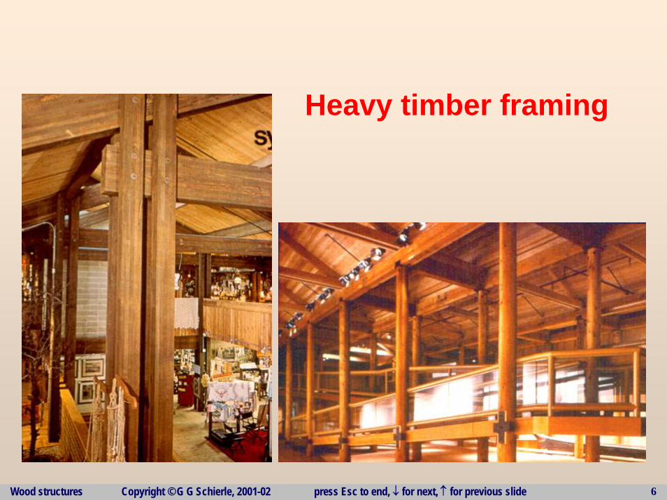
Heavy timber framing
Wood structures Copyright © G G Schierle, 2001-02 press Esc to end, ↓ for next, ↑ for previous slide 7
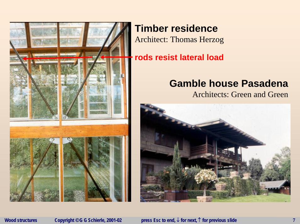
Timber residenceArchitect: Thomas Herzog
rods resist lateral load
Gamble house PasadenaArchitects: Green and Green
Wood structures Copyright © G G Schierle, 2001-02 press Esc to end, ↓ for next, ↑ for previous slide 8
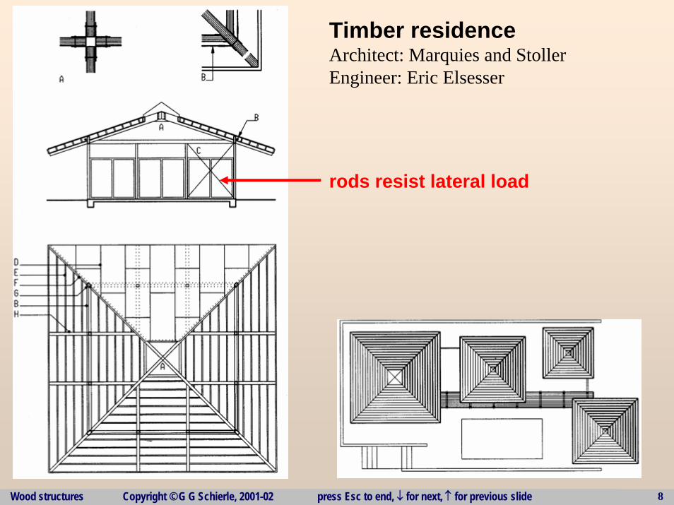
Timber residenceArchitect: Marquies and StollerEngineer: Eric Elsesser
rods resist lateral load
Wood structures Copyright © G G Schierle, 2001-02 press Esc to end, ↓ for next, ↑ for previous slide 9
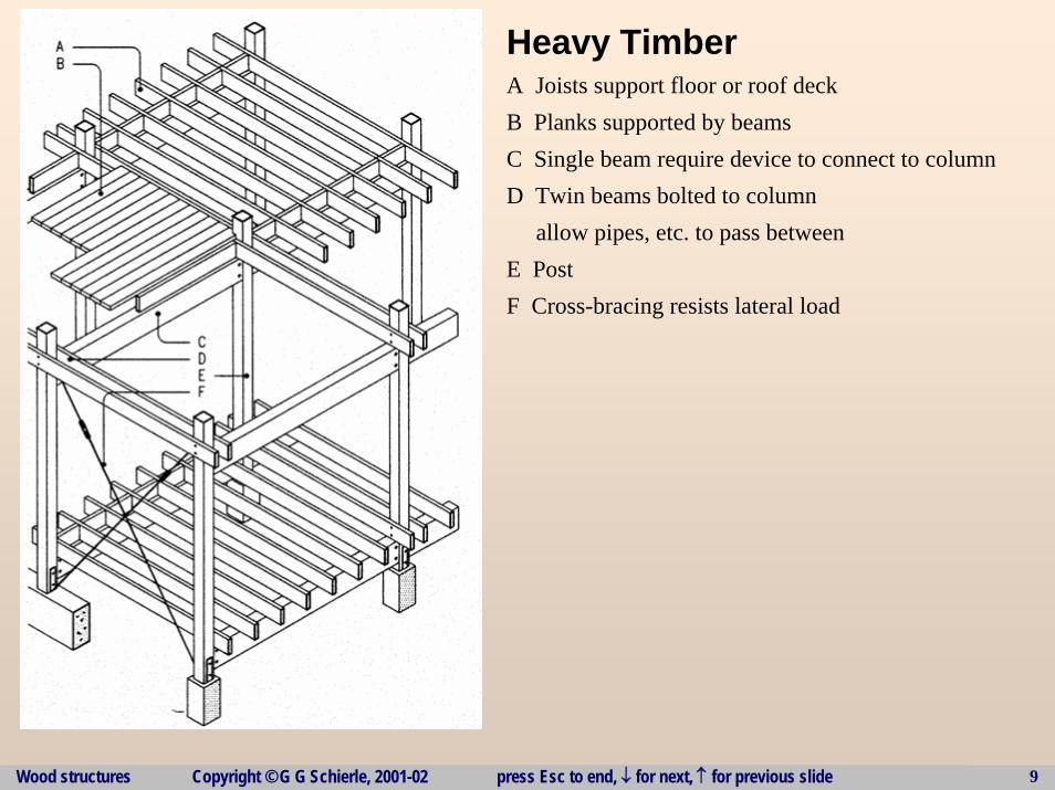
Heavy Timber A Joists support floor or roof deckB Planks supported by beamsC Single beam require device to connect to columnD Twin beams bolted to column
allow pipes, etc. to pass betweenE PostF Cross-bracing resists lateral load
Wood structures Copyright © G G Schierle, 2001-02 press Esc to end, ↓ for next, ↑ for previous slide 10
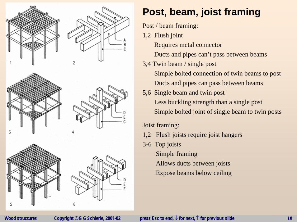
Post, beam, joist framingPost / beam framing:1,2 Flush joint
Requires metal connectorDucts and pipes can’t pass between beams
3,4 Twin beam / single postSimple bolted connection of twin beams to postDucts and pipes can pass between beams
5,6 Single beam and twin postLess buckling strength than a single postSimple bolted joint of single beam to twin posts
Joist framing:1,2 Flush joists require joist hangers3-6 Top joists
Simple framingAllows ducts between joistsExpose beams below ceiling
Wood structures Copyright © G G Schierle, 2001-02 press Esc to end, ↓ for next, ↑ for previous slide 11
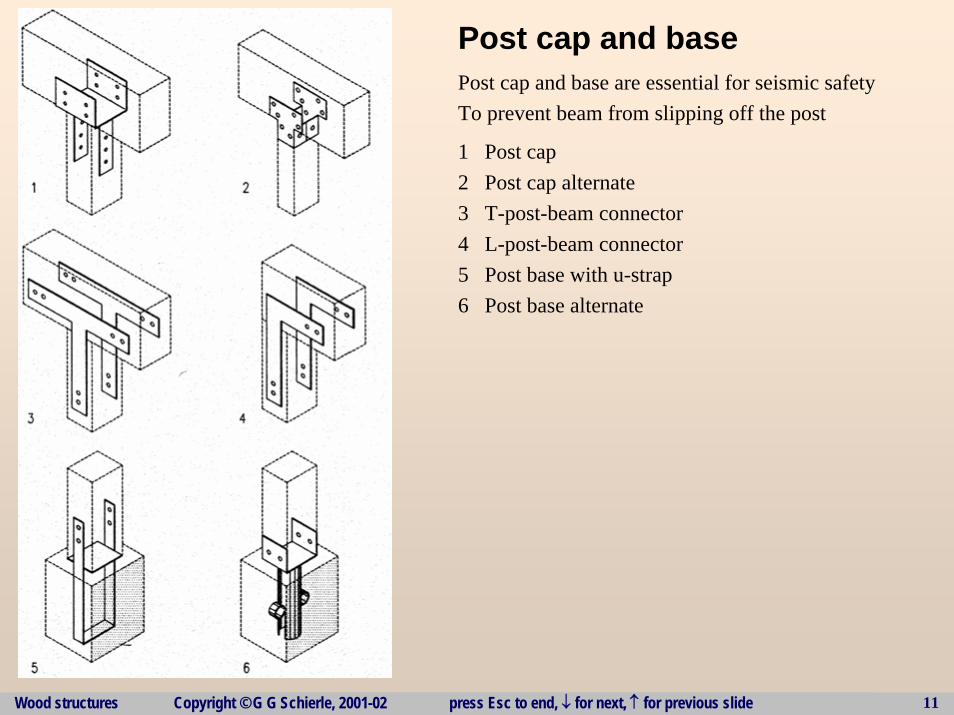
Post cap and basePost cap and base are essential for seismic safetyTo prevent beam from slipping off the post
1 Post cap2 Post cap alternate3 T-post-beam connector4 L-post-beam connector5 Post base with u-strap6 Post base alternate
Wood structures Copyright © G G Schierle, 2001-02 press Esc to end, ↓ for next, ↑ for previous slide 12
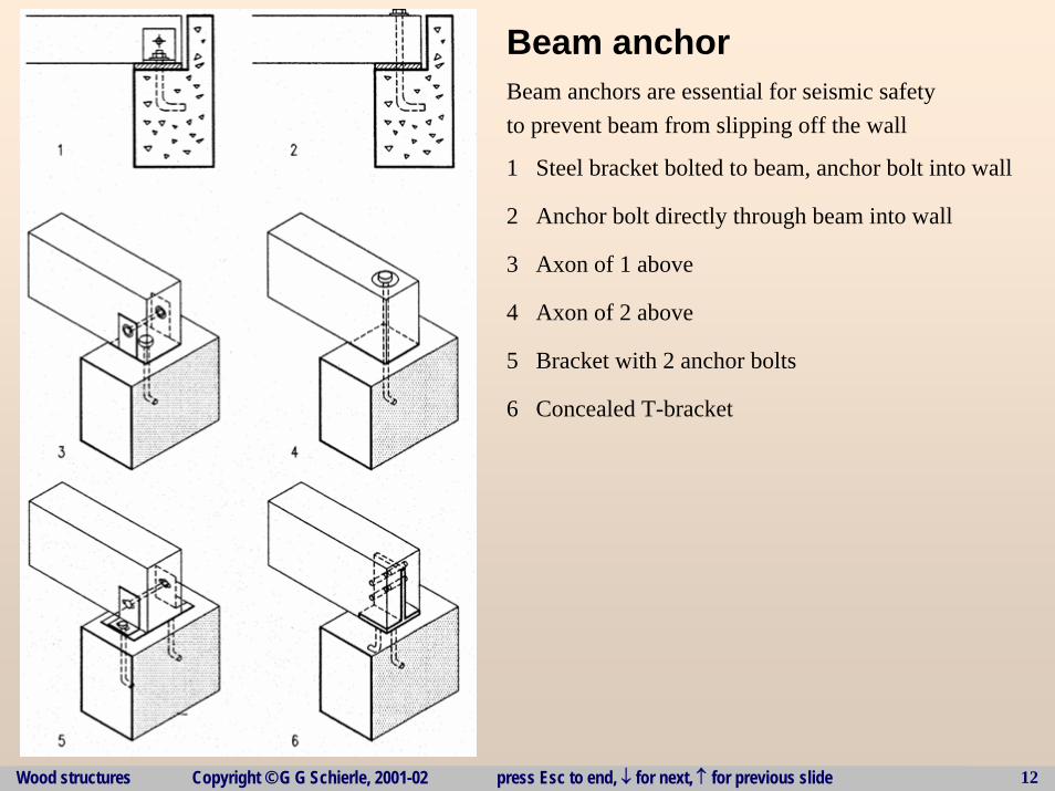
Beam anchor Beam anchors are essential for seismic safetyto prevent beam from slipping off the wall
1 Steel bracket bolted to beam, anchor bolt into wall
2 Anchor bolt directly through beam into wall
3 Axon of 1 above
4 Axon of 2 above
5 Bracket with 2 anchor bolts
6 Concealed T-bracket
Wood structures Copyright © G G Schierle, 2001-02 press Esc to end, ↓ for next, ↑ for previous slide 13
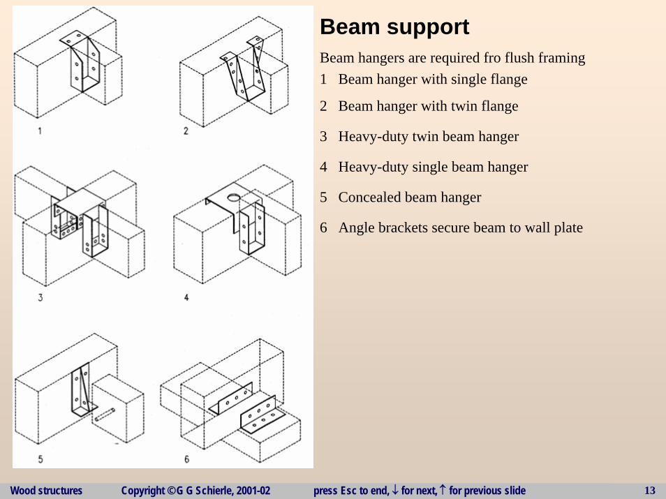
Beam support Beam hangers are required fro flush framing1 Beam hanger with single flange
2 Beam hanger with twin flange
3 Heavy-duty twin beam hanger
4 Heavy-duty single beam hanger
5 Concealed beam hanger
6 Angle brackets secure beam to wall plate
Wood structures Copyright © G G Schierle, 2001-02 press Esc to end, ↓ for next, ↑ for previous slide 14
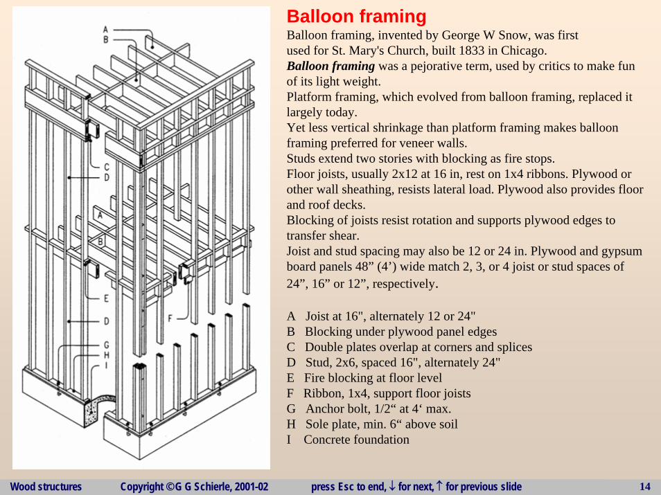
Balloon framingBalloon framing, invented by George W Snow, was firstused for St. Mary's Church, built 1833 in Chicago. Balloon framing was a pejorative term, used by critics to make funof its light weight. Platform framing, which evolved from balloon framing, replaced itlargely today.Yet less vertical shrinkage than platform framing makes balloonframing preferred for veneer walls. Studs extend two stories with blocking as fire stops. Floor joists, usually 2x12 at 16 in, rest on 1x4 ribbons. Plywood orother wall sheathing, resists lateral load. Plywood also provides floorand roof decks. Blocking of joists resist rotation and supports plywood edges totransfer shear. Joist and stud spacing may also be 12 or 24 in. Plywood and gypsumboard panels 48” (4’) wide match 2, 3, or 4 joist or stud spaces of24”, 16” or 12”, respectively.
A Joist at 16", alternately 12 or 24"B Blocking under plywood panel edgesC Double plates overlap at corners and splicesD Stud, 2x6, spaced 16", alternately 24"E Fire blocking at floor levelF Ribbon, 1x4, support floor joistsG Anchor bolt, 1/2“ at 4‘ max.H Sole plate, min. 6“ above soilI Concrete foundation
Wood structures Copyright © G G Schierle, 2001-02 press Esc to end, ↓ for next, ↑ for previous slide 15
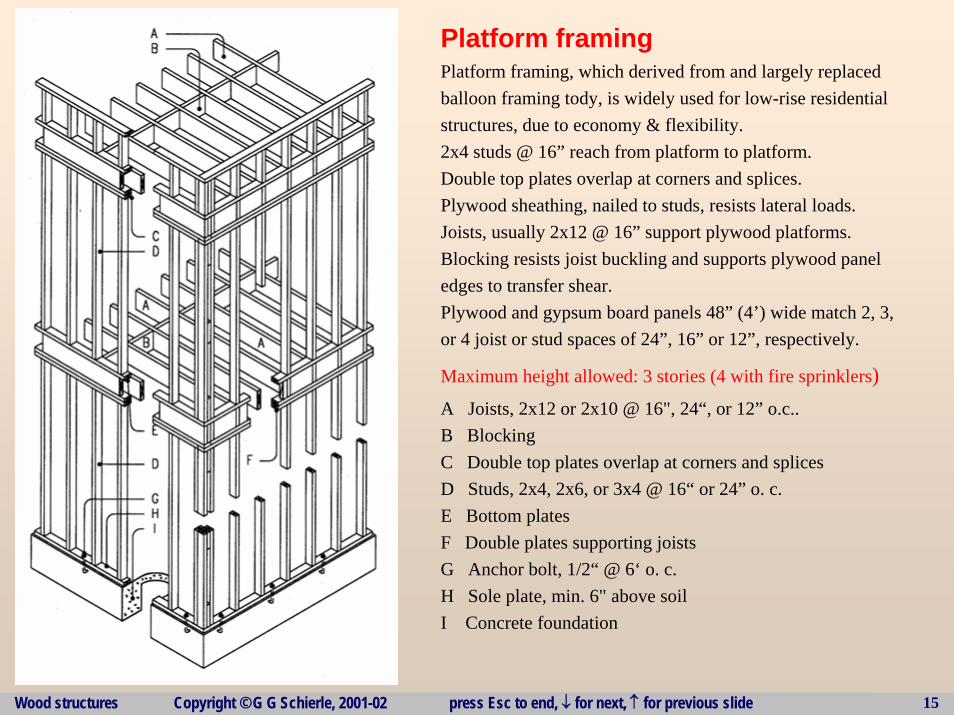
Platform framingPlatform framing, which derived from and largely replacedballoon framing tody, is widely used for low-rise residentialstructures, due to economy & flexibility.2x4 studs @ 16” reach from platform to platform.Double top plates overlap at corners and splices.Plywood sheathing, nailed to studs, resists lateral loads. Joists, usually 2x12 @ 16” support plywood platforms. Blocking resists joist buckling and supports plywood paneledges to transfer shear. Plywood and gypsum board panels 48” (4’) wide match 2, 3,or 4 joist or stud spaces of 24”, 16” or 12”, respectively.
Maximum height allowed: 3 stories (4 with fire sprinklers)A Joists, 2x12 or 2x10 @ 16", 24“, or 12” o.c..B BlockingC Double top plates overlap at corners and splices D Studs, 2x4, 2x6, or 3x4 @ 16“ or 24” o. c.E Bottom platesF Double plates supporting joistsG Anchor bolt, 1/2“ @ 6‘ o. c.H Sole plate, min. 6" above soilI Concrete foundation
Wood structures Copyright © G G Schierle, 2001-02 press Esc to end, ↓ for next, ↑ for previous slide 16
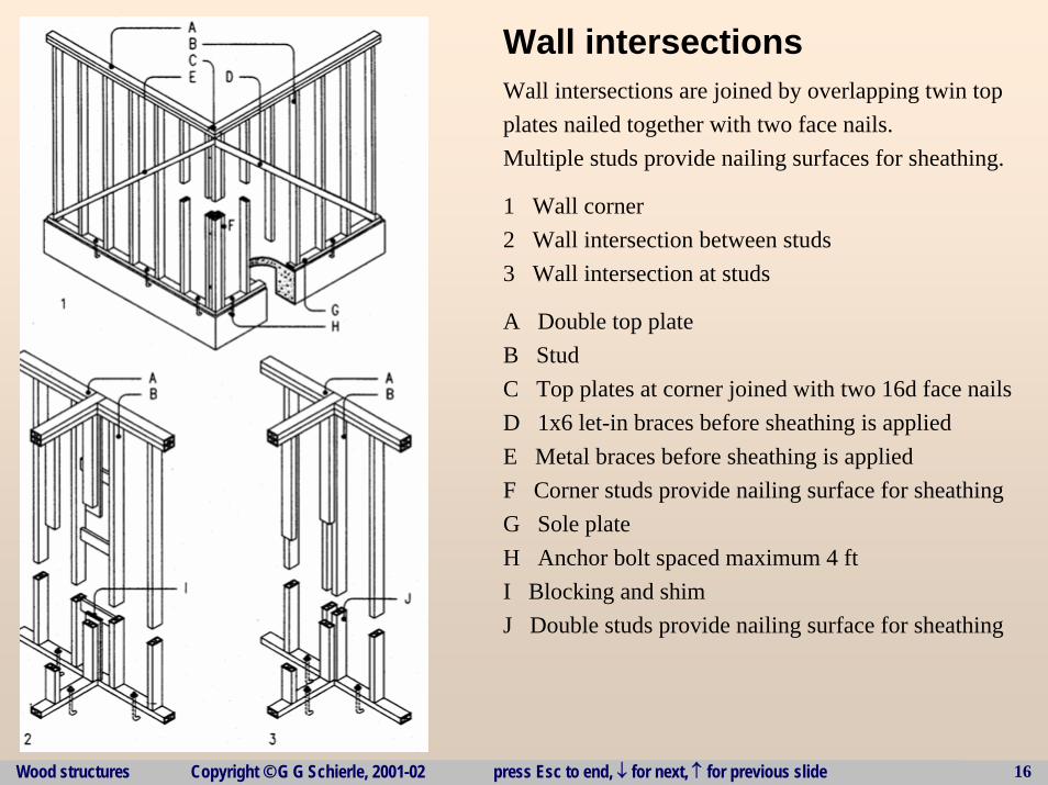
Wall intersections Wall intersections are joined by overlapping twin topplates nailed together with two face nails. Multiple studs provide nailing surfaces for sheathing.
1 Wall corner2 Wall intersection between studs3 Wall intersection at studs
A Double top plateB StudC Top plates at corner joined with two 16d face nailsD 1x6 let-in braces before sheathing is appliedE Metal braces before sheathing is appliedF Corner studs provide nailing surface for sheathingG Sole plateH Anchor bolt spaced maximum 4 ftI Blocking and shimJ Double studs provide nailing surface for sheathing
Wood structures Copyright © G G Schierle, 2001-02 press Esc to end, ↓ for next, ↑ for previous slide 17
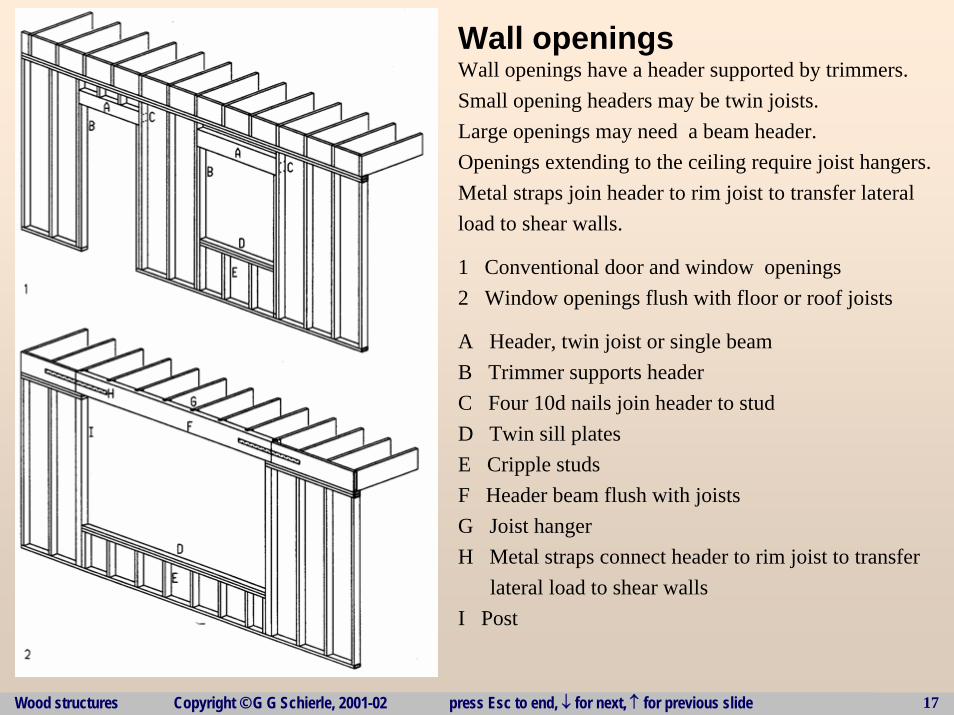
Wall openings Wall openings have a header supported by trimmers. Small opening headers may be twin joists.Large openings may need a beam header. Openings extending to the ceiling require joist hangers.Metal straps join header to rim joist to transfer lateralload to shear walls.
1 Conventional door and window openings2 Window openings flush with floor or roof joists
A Header, twin joist or single beamB Trimmer supports headerC Four 10d nails join header to studD Twin sill platesE Cripple studsF Header beam flush with joistsG Joist hangerH Metal straps connect header to rim joist to transfer
lateral load to shear wallsI Post
Wood structures Copyright © G G Schierle, 2001-02 press Esc to end, ↓ for next, ↑ for previous slide 18
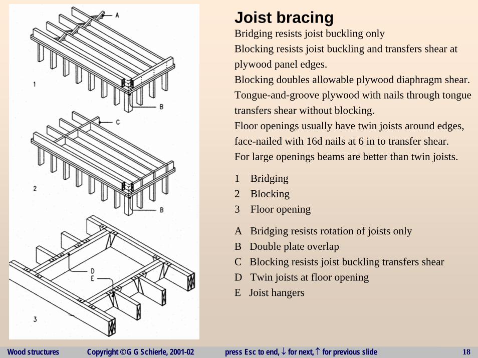
Joist bracing Bridging resists joist buckling onlyBlocking resists joist buckling and transfers shear atplywood panel edges.Blocking doubles allowable plywood diaphragm shear.Tongue-and-groove plywood with nails through tonguetransfers shear without blocking.Floor openings usually have twin joists around edges,face-nailed with 16d nails at 6 in to transfer shear. For large openings beams are better than twin joists.
1 Bridging2 Blocking3 Floor opening
A Bridging resists rotation of joists onlyB Double plate overlapC Blocking resists joist buckling transfers shearD Twin joists at floor openingE Joist hangers
Wood structures Copyright © G G Schierle, 2001-02 press Esc to end, ↓ for next, ↑ for previous slide 19
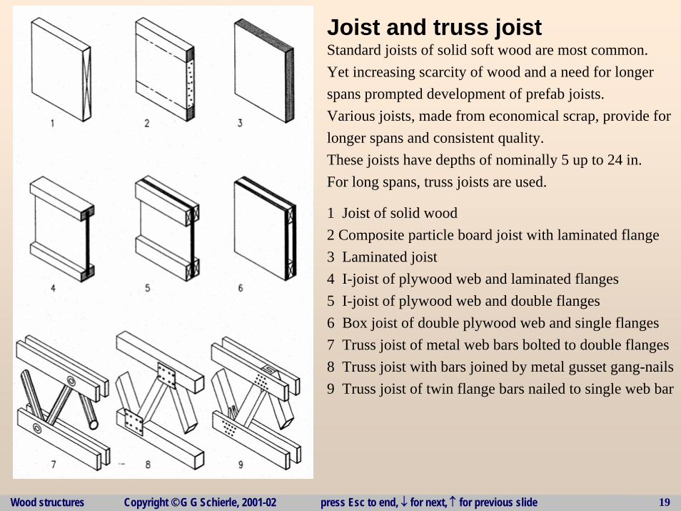
Joist and truss joist Standard joists of solid soft wood are most common.Yet increasing scarcity of wood and a need for longerspans prompted development of prefab joists.Various joists, made from economical scrap, provide forlonger spans and consistent quality.These joists have depths of nominally 5 up to 24 in.For long spans, truss joists are used.
1 Joist of solid wood2 Composite particle board joist with laminated flange3 Laminated joist4 I-joist of plywood web and laminated flanges5 I-joist of plywood web and double flanges6 Box joist of double plywood web and single flanges7 Truss joist of metal web bars bolted to double flanges8 Truss joist with bars joined by metal gusset gang-nails9 Truss joist of twin flange bars nailed to single web bar
Wood structures Copyright © G G Schierle, 2001-02 press Esc to end, ↓ for next, ↑ for previous slide 20
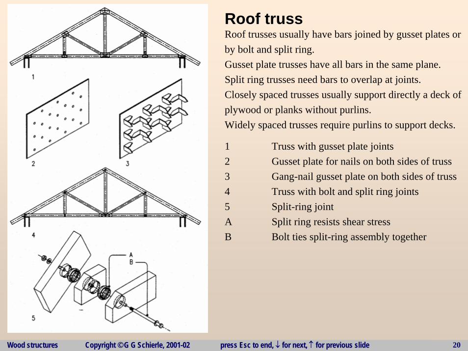
Roof truss Roof trusses usually have bars joined by gusset plates orby bolt and split ring. Gusset plate trusses have all bars in the same plane. Split ring trusses need bars to overlap at joints. Closely spaced trusses usually support directly a deck ofplywood or planks without purlins.Widely spaced trusses require purlins to support decks.
1 Truss with gusset plate joints2 Gusset plate for nails on both sides of truss3 Gang-nail gusset plate on both sides of truss4 Truss with bolt and split ring joints5 Split-ring jointA Split ring resists shear stressB Bolt ties split-ring assembly together
Wood structures Copyright © G G Schierle, 2001-02 press Esc to end, ↓ for next, ↑ for previous slide 21
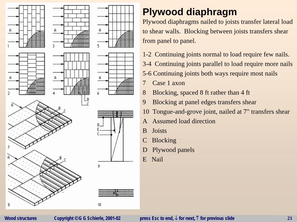
Plywood diaphragm Plywood diaphragms nailed to joists transfer lateral loadto shear walls. Blocking between joists transfers shearfrom panel to panel.
1-2 Continuing joints normal to load require few nails. 3-4 Continuing joints parallel to load require more nails5-6 Continuing joints both ways require most nails7 Case 1 axon8 Blocking, spaced 8 ft rather than 4 ft9 Blocking at panel edges transfers shear10 Tongue-and-grove joint, nailed at 7" transfers shearA Assumed load directionB Joists C BlockingD Plywood panelsE Nail
Wood structures Copyright © G G Schierle, 2001-02 press Esc to end, ↓ for next, ↑ for previous slide 22
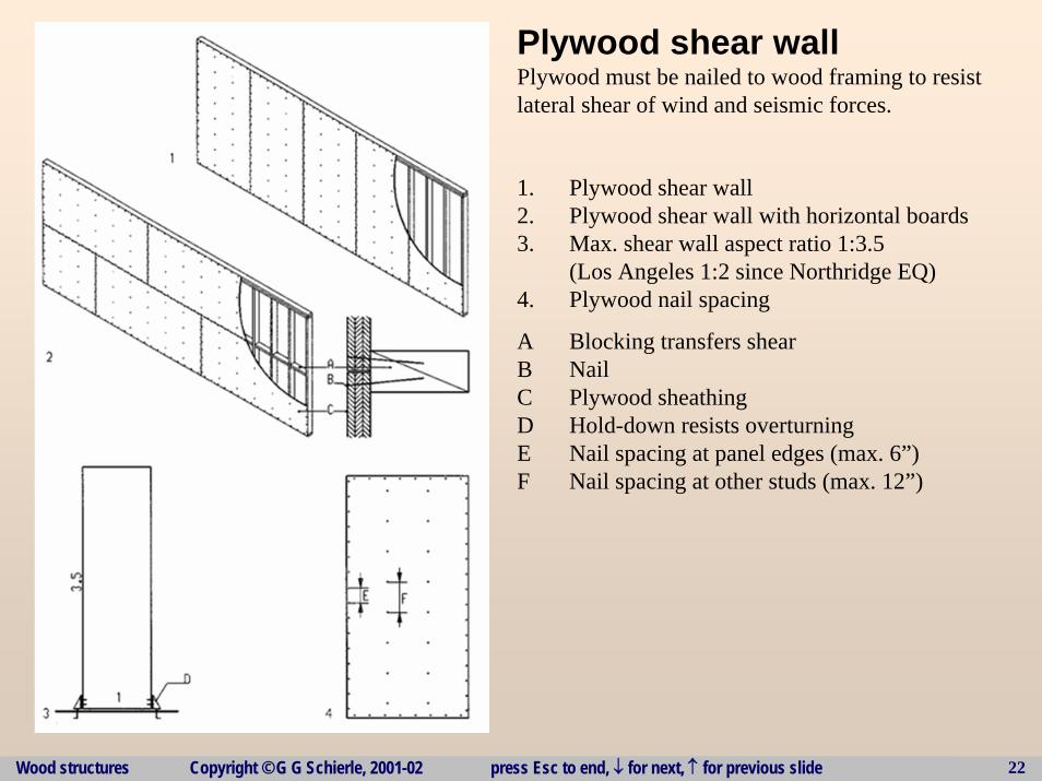
Plywood shear wallPlywood must be nailed to wood framing to resistlateral shear of wind and seismic forces.
1. Plywood shear wall 2. Plywood shear wall with horizontal boards3. Max. shear wall aspect ratio 1:3.5
(Los Angeles 1:2 since Northridge EQ)4. Plywood nail spacing
A Blocking transfers shearB NailC Plywood sheathingD Hold-down resists overturningE Nail spacing at panel edges (max. 6”)F Nail spacing at other studs (max. 12”)
Wood structures Copyright © G G Schierle, 2001-02 press Esc to end, ↓ for next, ↑ for previous slide 23
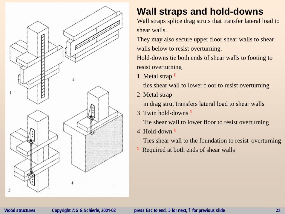
Wall straps and hold-downs Wall straps splice drag struts that transfer lateral load toshear walls. They may also secure upper floor shear walls to shearwalls below to resist overturning.Hold-downs tie both ends of shear walls to footing toresist overturning1 Metal strap 1
ties shear wall to lower floor to resist overturning2 Metal strap
in drag strut transfers lateral load to shear walls3 Twin hold-downs 1
Tie shear wall to lower floor to resist overturning4 Hold-down 1
Ties shear wall to the foundation to resist overturning1 Required at both ends of shear walls
Wood structures Copyright © G G Schierle, 2001-02 press Esc to end, ↓ for next, ↑ for previous slide 24
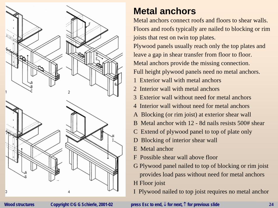
Metal anchors Metal anchors connect roofs and floors to shear walls.Floors and roofs typically are nailed to blocking or rimjoists that rest on twin top plates. Plywood panels usually reach only the top plates andleave a gap in shear transfer from floor to floor.Metal anchors provide the missing connection.Full height plywood panels need no metal anchors.1 Exterior wall with metal anchors2 Interior wall with metal anchors3 Exterior wall without need for metal anchors4 Interior wall without need for metal anchorsA Blocking (or rim joist) at exterior shear wallB Metal anchor with 12 - 8d nails resists 500# shearC Extend of plywood panel to top of plate onlyD Blocking of interior shear wallE Metal anchor F Possible shear wall above floorG Plywood panel nailed to top of blocking or rim joist
provides load pass without need for metal anchorsH Floor joistI Plywood nailed to top joist requires no metal anchor
Wood structures Copyright © G G Schierle, 2001-02 press Esc to end, ↓ for next, ↑ for previous slide 25
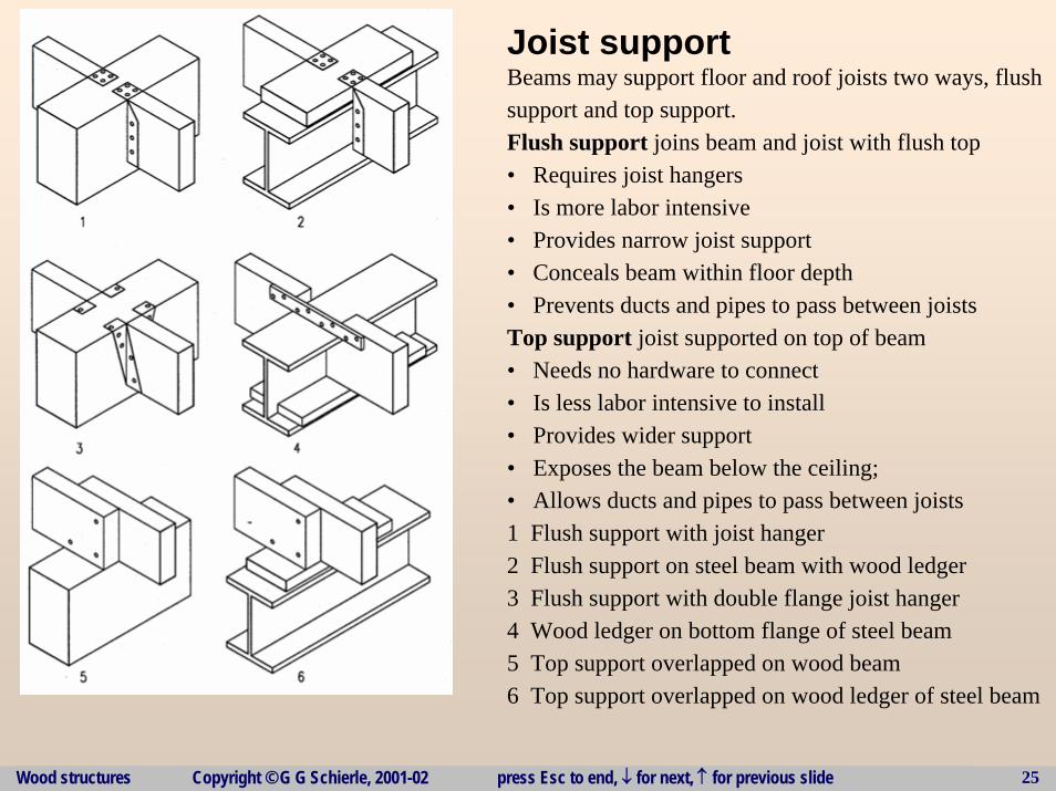
Joist support Beams may support floor and roof joists two ways, flushsupport and top support.Flush support joins beam and joist with flush top• Requires joist hangers• Is more labor intensive• Provides narrow joist support• Conceals beam within floor depth• Prevents ducts and pipes to pass between joistsTop support joist supported on top of beam• Needs no hardware to connect• Is less labor intensive to install• Provides wider support• Exposes the beam below the ceiling;• Allows ducts and pipes to pass between joists1 Flush support with joist hanger2 Flush support on steel beam with wood ledger3 Flush support with double flange joist hanger4 Wood ledger on bottom flange of steel beam5 Top support overlapped on wood beam6 Top support overlapped on wood ledger of steel beam
Wood structures Copyright © G G Schierle, 2001-02 press Esc to end, ↓ for next, ↑ for previous slide 26
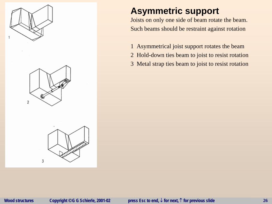
Asymmetric support Joists on only one side of beam rotate the beam. Such beams should be restraint against rotation
1 Asymmetrical joist support rotates the beam2 Hold-down ties beam to joist to resist rotation3 Metal strap ties beam to joist to resist rotation
Wood structures Copyright © G G Schierle, 2001-02 press Esc to end, ↓ for next, ↑ for previous slide 27
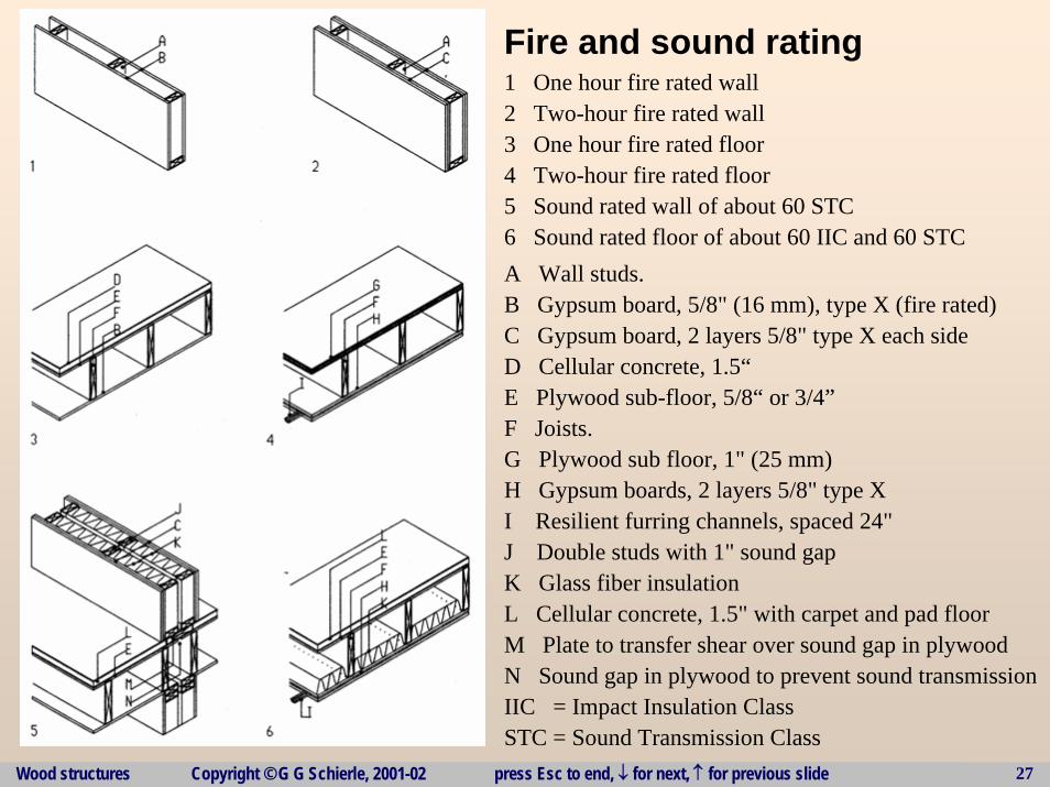
Fire and sound rating 1 One hour fire rated wall2 Two-hour fire rated wall3 One hour fire rated floor4 Two-hour fire rated floor5 Sound rated wall of about 60 STC6 Sound rated floor of about 60 IIC and 60 STCA Wall studs.B Gypsum board, 5/8" (16 mm), type X (fire rated)C Gypsum board, 2 layers 5/8" type X each sideD Cellular concrete, 1.5“E Plywood sub-floor, 5/8“ or 3/4”F Joists.G Plywood sub floor, 1" (25 mm)H Gypsum boards, 2 layers 5/8" type XI Resilient furring channels, spaced 24"J Double studs with 1" sound gapK Glass fiber insulationL Cellular concrete, 1.5" with carpet and pad floorM Plate to transfer shear over sound gap in plywoodN Sound gap in plywood to prevent sound transmissionIIC = Impact Insulation ClassSTC = Sound Transmission Class
Wood structures Copyright © G G Schierle, 2001-02 press Esc to end, ↓ for next, ↑ for previous slide 28
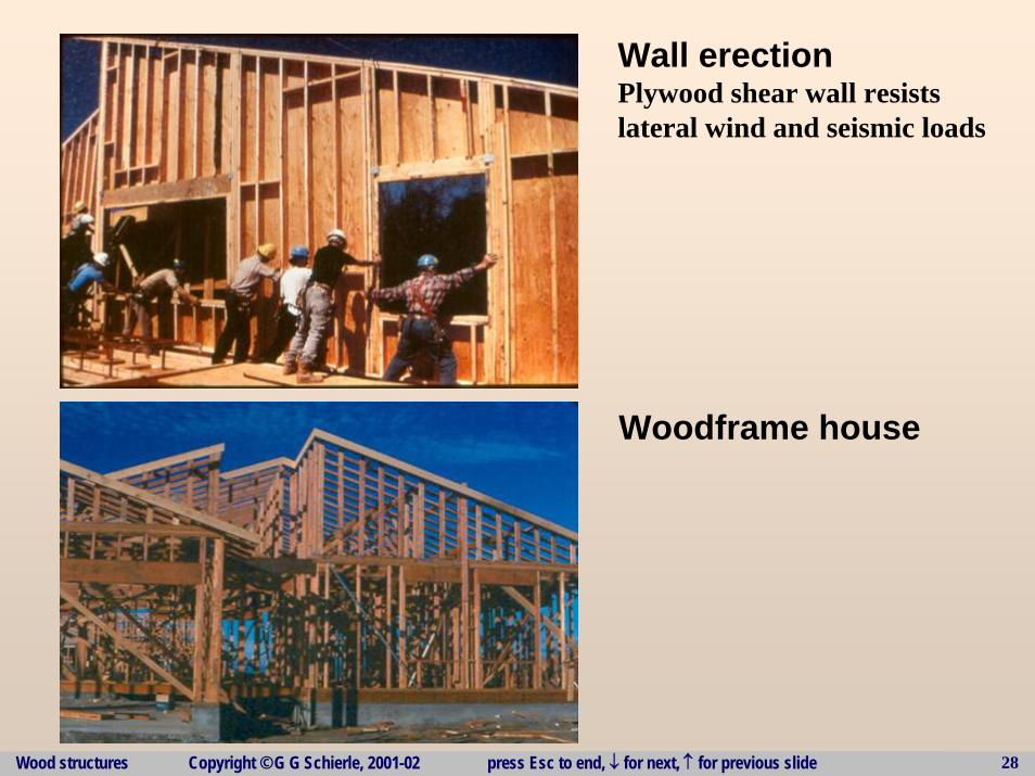
Woodframe house
Wall erectionPlywood shear wall resists lateral wind and seismic loads
Wood structures Copyright © G G Schierle, 2001-02 press Esc to end, ↓ for next, ↑ for previous slide 29
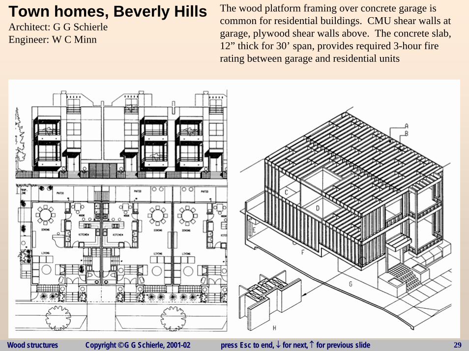
Town homes, Beverly HillsArchitect: G G SchierleEngineer: W C Minn
The wood platform framing over concrete garage is common for residential buildings. CMU shear walls atgarage, plywood shear walls above. The concrete slab,12” thick for 30’ span, provides required 3-hour firerating between garage and residential units
Wood structures Copyright © G G Schierle, 2001-02 press Esc to end, ↓ for next, ↑ for previous slide 30
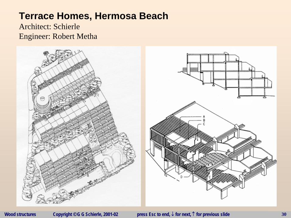
Terrace Homes, Hermosa BeachArchitect: SchierleEngineer: Robert Metha
Wood structures Copyright © G G Schierle, 2001-02 press Esc to end, ↓ for next, ↑ for previous slide 31
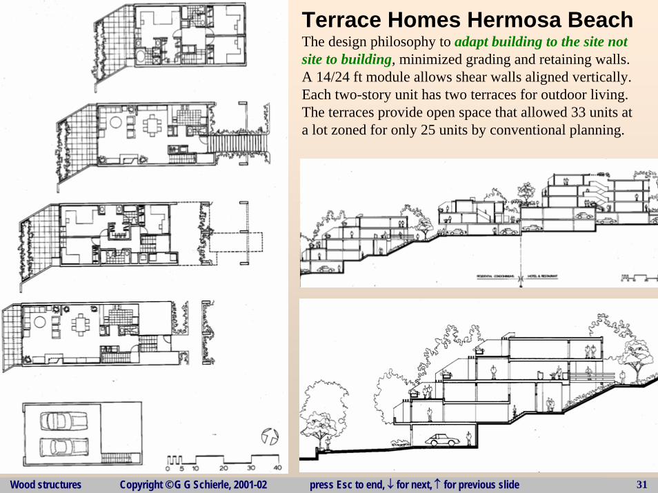
Terrace Homes Hermosa BeachThe design philosophy to adapt building to the site not site to building, minimized grading and retaining walls.A 14/24 ft module allows shear walls aligned vertically.Each two-story unit has two terraces for outdoor living.The terraces provide open space that allowed 33 units ata lot zoned for only 25 units by conventional planning.
Wood structures Copyright © G G Schierle, 2001-02 press Esc to end, ↓ for next, ↑ for previous slide 32
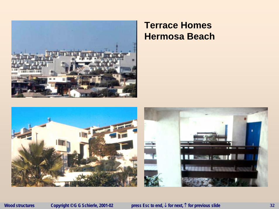
Terrace HomesHermosa Beach
Wood structures Copyright © G G Schierle, 2001-02 press Esc to end, ↓ for next, ↑ for previous slide 33
Wood structures Copyright © G G Schierle, 2001-02 press Esc to end, ↓ for next, ↑ for previous slide 34
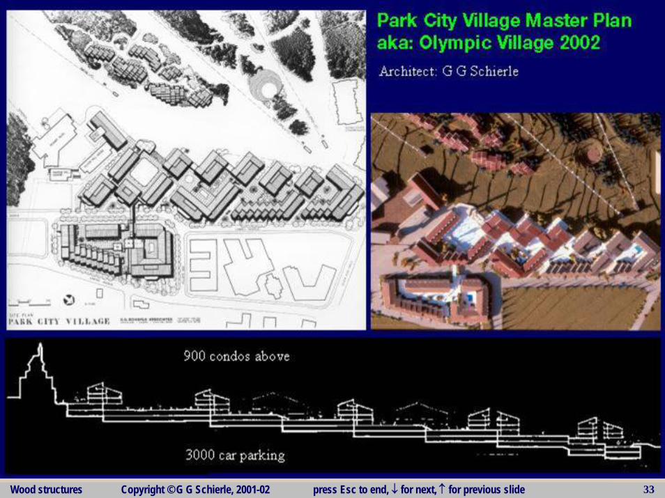
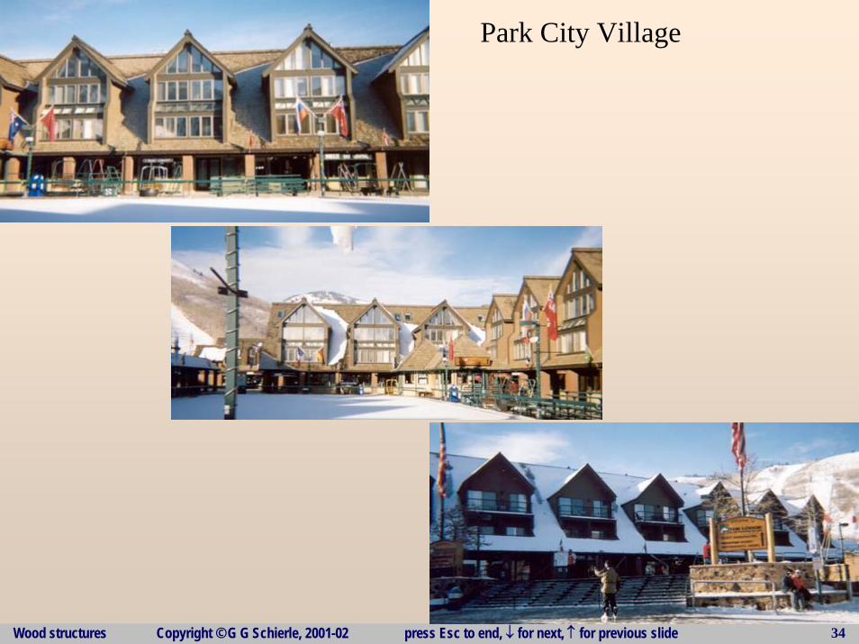
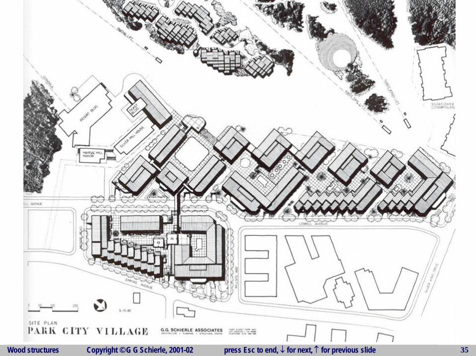
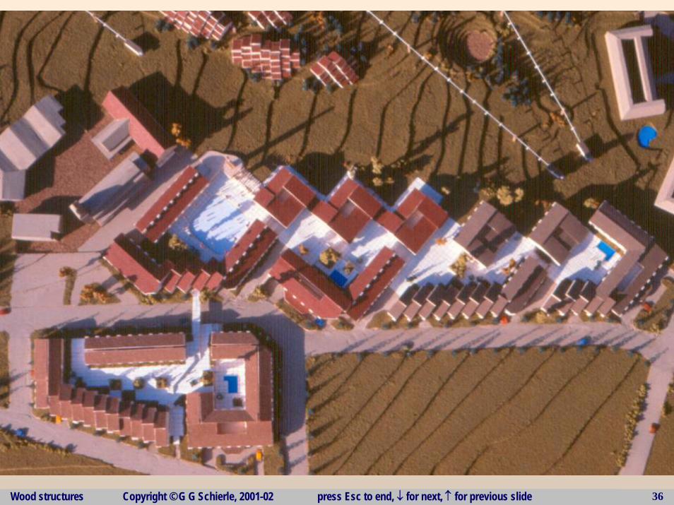
Park City Village
Wood structures Copyright © G G Schierle, 2001-02 press Esc to end, ↓ for next, ↑ for previous slide 35
Wood structures Copyright © G G Schierle, 2001-02 press Esc to end, ↓ for next, ↑ for previous slide 36