Embed Size (px)
Citation preview
Boiler Manual Wood Pellet Boiler WS18/WP18 For use with ENplus A1 wood pellets only. Look for the ENplus A1 symbol.
Incorporating: User Instructions Installation Instructions Service Record Guarantee Terms & Conditions Registration Documents
LEAVE THIS MANUAL WITH THE END USER
IMPORTANT – Read this manual in full before installing, commissioning, servicing or operating this appliance.
COMMISSIONING This appliance must be commissioned by a Warmflow engineer or other qualified biomass engineer in accordance with Section 4.1 of this manual. Failure to commission the appliance will invalidate the warranty.
REGISTRATION After commissioning, ensure that the appliance registration documents are completed and returned to Warmflow. See Section 7 of this manual.
SERVICING To ensure continued reliable operation, fuel economy and to validate the guarantee, the appliance must be serviced when indicated by the user control interface. Servicing must be conducted by a Warmflow engineer or other qualified biomass engineer in accordance with Section 4.2 of this manual. A service history must be maintained in Section 8 of this manual.
NI Customers Only Warmflow Engineering customer care (NI) provides an excellent back-up service, operating a team of trained engineers who can meet all the servicing, commissioning and breakdown requirements for your appliance. Tel: 028 9262 1515 Fax: 028 9262 0869 E-mail: [email protected] Web: www.warmflow.co.uk
For Parts, Service, Technical & Warranty Contact Great Britain & N. Ireland, Tel: 028 9262 1515 Republic of Ireland, Tel: 048 9262 1515 LISBURN TELFORD Lissue Industrial Estate, Moira Road, Unit D1, Hortonpark, Lisburn, Co. Antrim, N. Ireland, BT28 2RF Hortonwood 7, Telford, TF1 7GX Tel: (028) 9262 1515 Tel: (01952) 607 750 Fax: (028) 9262 0869 Fax: (01952) 603 983 E-mail: [email protected] E-mail: [email protected] [email protected] [email protected] [email protected] [email protected]
CONTENTS 1 KEY INFORMATION .............................................................................................................. 4
2 USER INSTRUCTIONS ......................................................................................................... 72.1 Filling the Pellet Hopper ................................................................................................................ 72.2 User Control Interface ................................................................................................................... 7
2.2.1 Home Screen Icons and their meaning. .............................................................................................. 8
2.2.2 Using the Main Menu .......................................................................................................................... 9
2.3 Cleaning ...................................................................................................................................... 20
2.3.1 Cleaning Scheduler ........................................................................................................................... 20
2.3.2 Cleaning Status ................................................................................................................................. 21
2.3.3 Cleaning Procedure ........................................................................................................................... 24
3 INSTALLATION REQUIREMENTS ..................................................................................... 383.1 The Clean Air Act 1993 and Smoke Control Areas .................................................................... 393.2 General Requirements ................................................................................................................ 40
3.2.1 Transportation aids and hearth ......................................................................................................... 40
3.2.2 Service Access .................................................................................................................................. 41
3.2.3 Heating System ................................................................................................................................. 41
3.2.4 Air Vents ............................................................................................................................................ 42
3.2.5 Drain Cock ......................................................................................................................................... 42
3.2.6 Pipework ............................................................................................................................................ 42
3.2.7 Heating System Design ..................................................................................................................... 42
3.3 Sealed Systems .......................................................................................................................... 423.3.1 Expansion Vessel (WS 18 Models only) ........................................................................................... 42
3.4 System Filling ............................................................................................................................. 433.4.1 System Filling .................................................................................................................................... 43
3.4.2 System Pressure (WS 18 only) ......................................................................................................... 43
3.4.3 Pressure Relief Valve ........................................................................................................................ 43
3.4.4 Low Pressure Switch ......................................................................................................................... 43
3.4.5 Condensate Trap ............................................................................................................................... 44
3.5 Wiring Layout .............................................................................................................................. 463.6 Flue System ................................................................................................................................ 48
3.6.1 Flue Outlet Position ........................................................................................................................... 48
3.6.2 Flue Assembly ................................................................................................................................... 50
3.6.3 Extended Flue Assembly ................................................................................................................... 54
4 COMMISSIONING, SERVICING AND FLUE CLEANING ................................................... 564.1 Commissioning – Approximate time to complete: 2 hours .......................................................... 564.2 Servicing ..................................................................................................................................... 674.3 Flue Cleaning .............................................................................................................................. 67
5 ALARMS AND TROUBLESHOOTING ................................................................................ 68

5.1 Alarms ......................................................................................................................................... 685.2 Troubleshooting .......................................................................................................................... 76
6 YOUR GUARANTEES, TERMS & CONDITIONS ............................................................... 78
7 APPLIANCE INSTALLATION/COMMISSIONING CERTIFICATE & REGISTRATION. ..... 82
8 APPLIANCE SERVICE RECORDS. .................................................................................... 85
9 APPENDIX A – SUPPLEMENTARY INSTALLATION AND OPERATING INSTRUCTIONS FOR THE UK MARKET .............................................................................................................. 96
10 APPENDIX B – CUSTOMER CONNECTION WIRING SCHEMATIC ............................ 104
4
1 KEY INFORMATION
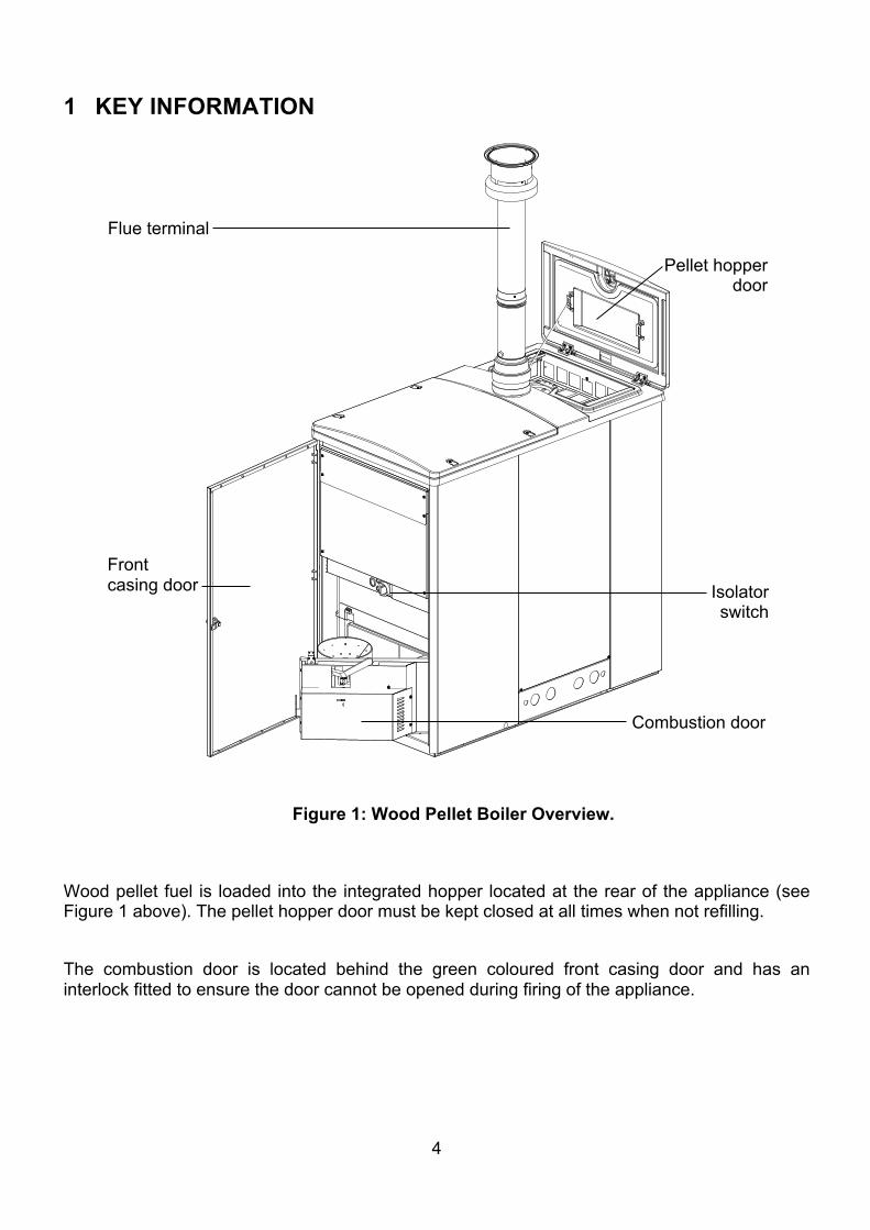
Wood pellet fuel is loaded into the integrated hopper located at the rear of the appliance (see Figure 1 above). The pellet hopper door must be kept closed at all times when not refilling. The combustion door is located behind the green coloured front casing door and has an interlock fitted to ensure the door cannot be opened during firing of the appliance.
Figure 1: Wood Pellet Boiler Overview.
Pellet hopper door
Combustion door
Isolator switch
Flue terminal
Front casing door
5
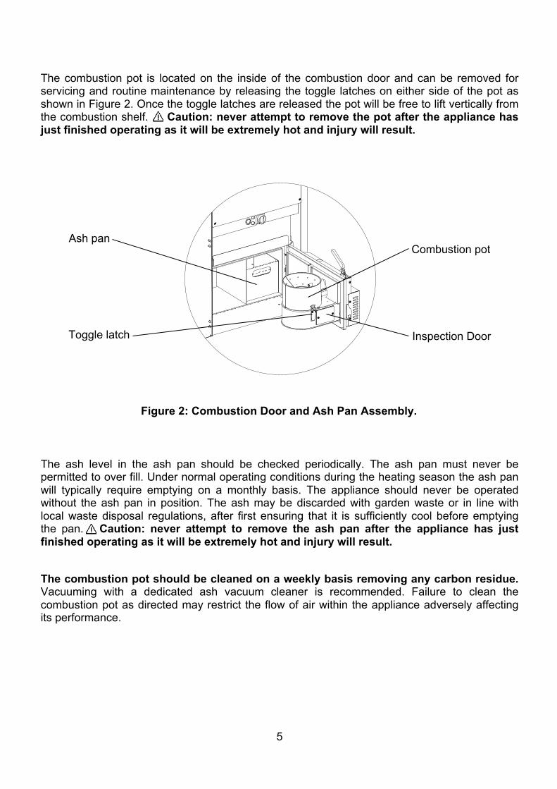
The combustion pot is located on the inside of the combustion door and can be removed for servicing and routine maintenance by releasing the toggle latches on either side of the pot as shown in Figure 2. Once the toggle latches are released the pot will be free to lift vertically from the combustion shelf. Caution: never attempt to remove the pot after the appliance has just finished operating as it will be extremely hot and injury will result.
The ash level in the ash pan should be checked periodically. The ash pan must never be permitted to over fill. Under normal operating conditions during the heating season the ash pan will typically require emptying on a monthly basis. The appliance should never be operated without the ash pan in position. The ash may be discarded with garden waste or in line with local waste disposal regulations, after first ensuring that it is sufficiently cool before emptying the pan. Caution: never attempt to remove the ash pan after the appliance has just finished operating as it will be extremely hot and injury will result. The combustion pot should be cleaned on a weekly basis removing any carbon residue. Vacuuming with a dedicated ash vacuum cleaner is recommended. Failure to clean the combustion pot as directed may restrict the flow of air within the appliance adversely affecting its performance.
Figure 2: Combustion Door and Ash Pan Assembly.
Ash pan Combustion pot
Toggle latch Inspection Door
6
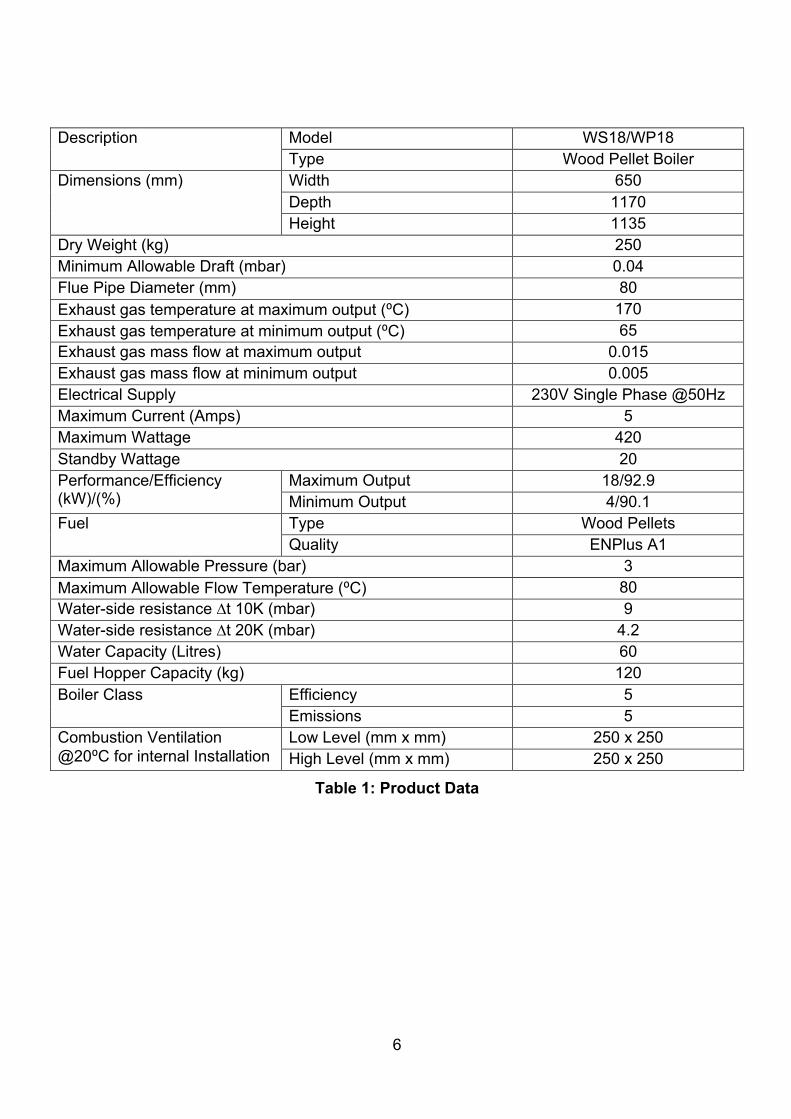
Description Model WS18/WP18 Type Wood Pellet Boiler
Dimensions (mm) Width 650 Depth 1170 Height 1135
Dry Weight (kg) 250 Minimum Allowable Draft (mbar) 0.04 Flue Pipe Diameter (mm) 80 Exhaust gas temperature at maximum output (⁰C) 170 Exhaust gas temperature at minimum output (⁰C) 65 Exhaust gas mass flow at maximum output 0.015 Exhaust gas mass flow at minimum output 0.005 Electrical Supply 230V Single Phase @50Hz Maximum Current (Amps) 5 Maximum Wattage 420 Standby Wattage 20 Performance/Efficiency (kW)/(%)
Maximum Output 18/92.9 Minimum Output 4/90.1
Fuel Type Wood Pellets Quality ENPlus A1
Maximum Allowable Pressure (bar) 3 Maximum Allowable Flow Temperature (⁰C) 80 Water-side resistance ∆t 10K (mbar) 9 Water-side resistance ∆t 20K (mbar) 4.2 Water Capacity (Litres) 60 Fuel Hopper Capacity (kg) 120 Boiler Class Efficiency 5
Emissions 5 Combustion Ventilation @20⁰C for internal Installation
Low Level (mm x mm) 250 x 250 High Level (mm x mm) 250 x 250
Table 1: Product Data
7
2 USER INSTRUCTIONS
2.1 Filling the Pellet Hopper The wood pellets used to fuel the appliance must be compliant with the ENPlus A1 pellet standard. Using alternative pellets will invalidate the product warranty and will have a negative effect on the operation and performance of the appliance. The wood pellet fuel must be stored in accordance with the wood pellet manufacturer’s guidelines and in a cool dry area away from sources of ignition, condensation, excess humidity or other sources of moisture. Whether stored in bags or in bulk it is important that care is taken to handle the wood pellets in such a way that ensures they won’t deteriorate and create dust. Care must be taken to avoid exposure of wood pellets to rain or other moisture during storage or filling. The use of deteriorated pellets will have a negative effect on the operation and performance of the appliance. The pellet hopper has a wood pellet capacity of 120kg. The user control interface will indicate when refilling of the hopper is necessary. To fill the pellet hopper, open the pellet hopper door (See Figure 1) and pour in the pellets. To protect the user a hopper safety guard is located in the top of the hopper beneath the pellet hopper door. This must not be removed. Once filling is complete, close the pellet hopper door. An interlock switch is fitted below the pellet hopper door meaning the appliance will not operate if the pellet hopper door has been left open. NOTE – The appliance will shut down before the pellet hopper runs completely empty. This is to avoid the auger feed mechanism becoming empty which would cause difficulty during start-up after the pellet hopper is re-filled.
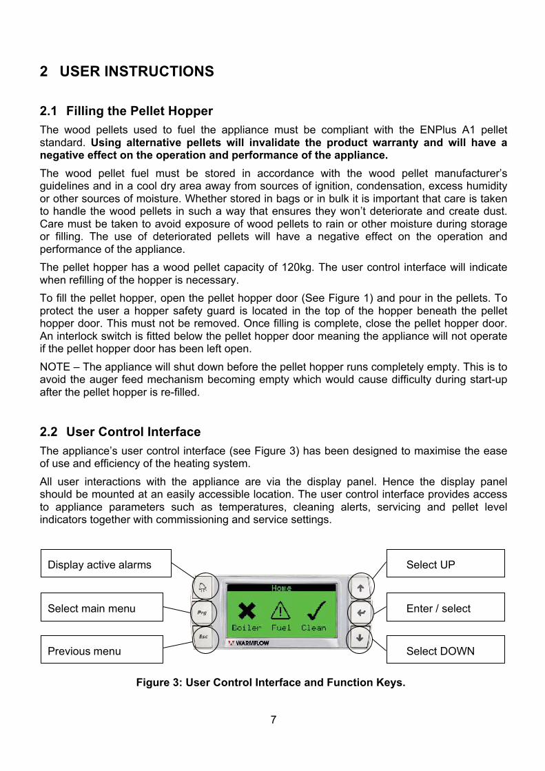
2.2 User Control Interface The appliance’s user control interface (see Figure 3) has been designed to maximise the ease of use and efficiency of the heating system. All user interactions with the appliance are via the display panel. Hence the display panel should be mounted at an easily accessible location. The user control interface provides access to appliance parameters such as temperatures, cleaning alerts, servicing and pellet level indicators together with commissioning and service settings.
Display active alarms
Select main menu
Previous menu
Select UP
Select DOWN
Enter / select
Figure 3: User Control Interface and Function Keys.
8
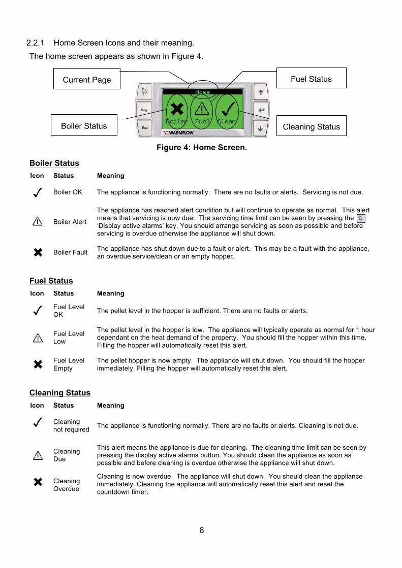
2.2.1 Home Screen Icons and their meaning. The home screen appears as shown in Figure 4. Boiler Status Icon Status Meaning
Boiler OK The appliance is functioning normally. There are no faults or alerts. Servicing is not due.
Boiler Alert
The appliance has reached alert condition but will continue to operate as normal. This alert means that servicing is now due. The servicing time limit can be seen by pressing the ‘Display active alarms’ key. You should arrange servicing as soon as possible and before servicing is overdue otherwise the appliance will shut down.
Boiler Fault The appliance has shut down due to a fault or alert. This may be a fault with the appliance,
an overdue service/clean or an empty hopper.
Fuel Status Icon Status Meaning
Fuel Level OK The pellet level in the hopper is sufficient. There are no faults or alerts.
Fuel Level Low
The pellet level in the hopper is low. The appliance will typically operate as normal for 1 hour dependant on the heat demand of the property. You should fill the hopper within this time. Filling the hopper will automatically reset this alert.
Fuel Level Empty
The pellet hopper is now empty. The appliance will shut down. You should fill the hopper immediately. Filling the hopper will automatically reset this alert.
Cleaning Status Icon Status Meaning
Cleaning not required The appliance is functioning normally. There are no faults or alerts. Cleaning is not due.
Cleaning Due
This alert means the appliance is due for cleaning. The cleaning time limit can be seen by pressing the display active alarms button. You should clean the appliance as soon as possible and before cleaning is overdue otherwise the appliance will shut down.
Cleaning Overdue
Cleaning is now overdue. The appliance will shut down. You should clean the appliance immediately. Cleaning the appliance will automatically reset this alert and reset the countdown timer.
Figure 4: Home Screen.
Fuel Status
Boiler Status
Current Page
Cleaning Status
9
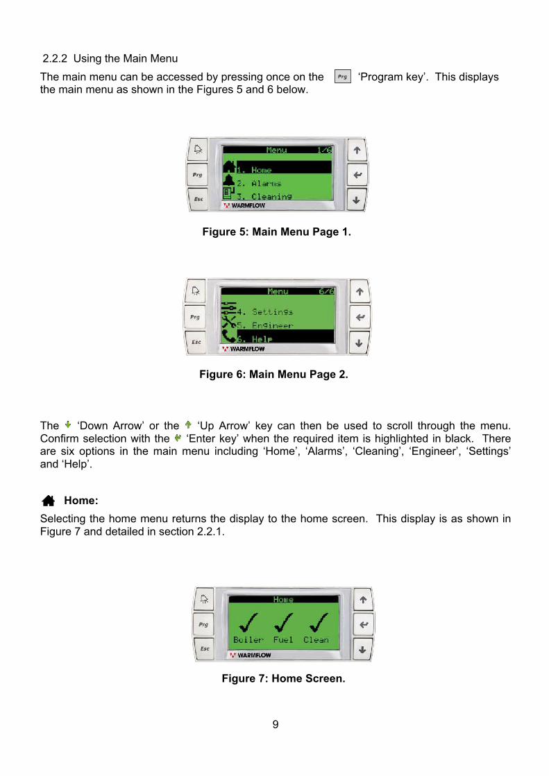
2.2.2 Using the Main Menu The main menu can be accessed by pressing once on the ‘Program key’. This displays the main menu as shown in the Figures 5 and 6 below.
The ‘Down Arrow’ or the ‘Up Arrow’ key can then be used to scroll through the menu. Confirm selection with the ‘Enter key’ when the required item is highlighted in black. There are six options in the main menu including ‘Home’, ‘Alarms’, ‘Cleaning’, ‘Engineer’, ‘Settings’ and ‘Help’.
Home: Selecting the home menu returns the display to the home screen. This display is as shown in Figure 7 and detailed in section 2.2.1.
Figure 5: Main Menu Page 1.
Figure 7: Home Screen.
Figure 6: Main Menu Page 2.
10
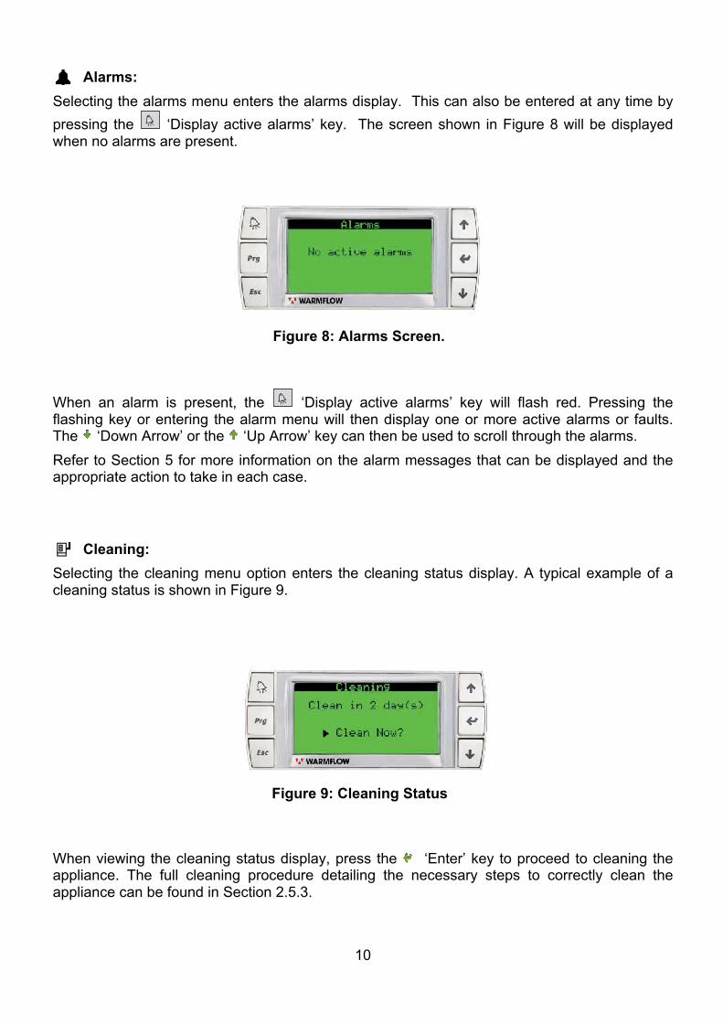
Alarms: Selecting the alarms menu enters the alarms display. This can also be entered at any time by pressing the ‘Display active alarms’ key. The screen shown in Figure 8 will be displayed when no alarms are present.
When an alarm is present, the ‘Display active alarms’ key will flash red. Pressing the flashing key or entering the alarm menu will then display one or more active alarms or faults. The ‘Down Arrow’ or the ‘Up Arrow’ key can then be used to scroll through the alarms. Refer to Section 5 for more information on the alarm messages that can be displayed and the appropriate action to take in each case.
Cleaning: Selecting the cleaning menu option enters the cleaning status display. A typical example of a cleaning status is shown in Figure 9.
When viewing the cleaning status display, press the ‘Enter’ key to proceed to cleaning the appliance. The full cleaning procedure detailing the necessary steps to correctly clean the appliance can be found in Section 2.5.3.
Figure 8: Alarms Screen.
Figure 9: Cleaning Status
11
Settings:
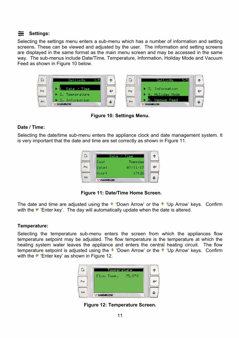
Selecting the settings menu enters a sub-menu which has a number of information and setting screens. These can be viewed and adjusted by the user. The information and setting screens are displayed in the same format as the main menu screen and may be accessed in the same way. The sub-menus include Date/Time, Temperature, Information, Holiday Mode and Vacuum Feed as shown in Figure 10 below.
Date / Time: Selecting the date/time sub-menu enters the appliance clock and date management system. It is very important that the date and time are set correctly as shown in Figure 11.
The date and time are adjusted using the ‘Down Arrow’ or the ‘Up Arrow’ keys. Confirm with the ‘Enter key’. The day will automatically update when the date is altered. Temperature: Selecting the temperature sub-menu enters the screen from which the appliances flow temperature setpoint may be adjusted. The flow temperature is the temperature at which the heating system water leaves the appliance and enters the central heating circuit. The flow temperature setpoint is adjusted using the ‘Down Arrow’ or the ‘Up Arrow’ keys. Confirm with the ‘Enter key’ as shown in Figure 12.
Figure 10: Settings Menu.
Figure 11: Date/Time Home Screen.
Figure 12: Temperature Screen.
12
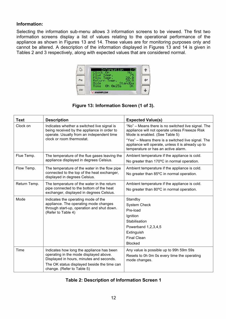
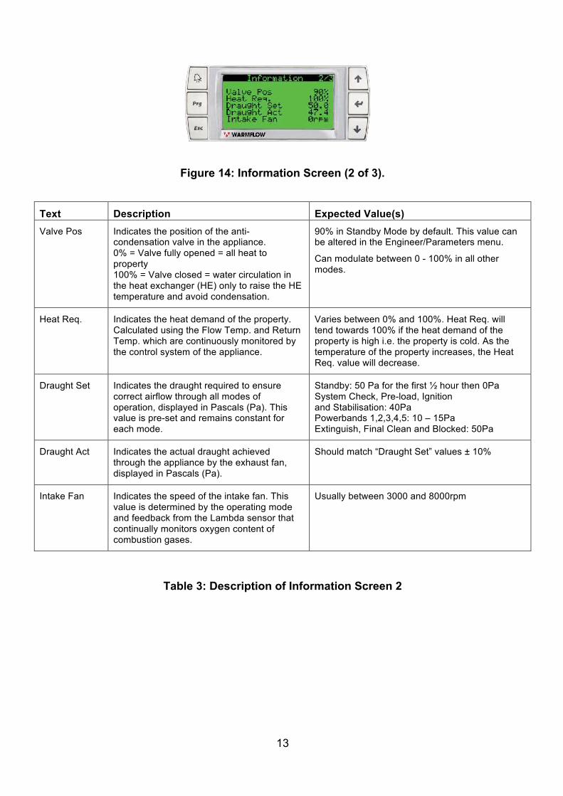
Information: Selecting the information sub-menu allows 3 information screens to be viewed. The first two information screens display a list of values relating to the operational performance of the appliance as shown in Figures 13 and 14. These values are for monitoring purposes only and cannot be altered. A description of the information displayed in Figures 13 and 14 is given in Tables 2 and 3 respectively, along with expected values that are considered normal.
Text Description Expected Value(s) Clock on Indicates whether a switched live signal is
being received by the appliance in order to operate. Usually from an independent time clock or room thermostat.
“No” – Means there is no switched live signal. The appliance will not operate unless Freeeze Risk Mode is enabled. (See Table 5) “Yes” – Means there is a switched live signal. The appliance will operate, unless it is already up to temperature or has an active alarm.
Flue Temp. The temperature of the flue gases leaving the appliance displayed in degrees Celsius.
Ambient temperature if the appliance is cold. No greater than 170⁰C in normal operation.
Flow Temp. The temperature of the water in the flow pipe connected to the top of the heat exchanger, displayed in degrees Celsius.
Ambient temperature if the appliance is cold. No greater than 85⁰C in normal operation.
Return Temp. The temperature of the water in the return pipe connected to the bottom of the heat exchanger, displayed in degrees Celsius.
Ambient temperature if the appliance is cold. No greater than 80⁰C in normal operation.
Mode Indicates the operating mode of the appliance. The operating mode changes through start-up, operation and shut down. (Refer to Table 4)
Standby System Check Pre-load Ignition Stabilisation Powerband 1,2,3,4,5 Extinguish Final Clean Blocked
Time Indicates how long the appliance has been operating in the mode displayed above. Displayed in hours, minutes and seconds. The OK status displayed beside the time can change. (Refer to Table 5)
Any value is possible up to 99h 59m 59s Resets to 0h 0m 0s every time the operating mode changes.
Table 2: Description of Information Screen 1
Figure 13: Information Screen (1 of 3).
13
Text Description Expected Value(s) Valve Pos Indicates the position of the anti-
condensation valve in the appliance. 0% = Valve fully opened = all heat to property 100% = Valve closed = water circulation in the heat exchanger (HE) only to raise the HE temperature and avoid condensation.
90% in Standby Mode by default. This value can be altered in the Engineer/Parameters menu.
Can modulate between 0 - 100% in all other modes.
Heat Req. Indicates the heat demand of the property. Calculated using the Flow Temp. and Return Temp. which are continuously monitored by the control system of the appliance.
Varies between 0% and 100%. Heat Req. will tend towards 100% if the heat demand of the property is high i.e. the property is cold. As the temperature of the property increases, the Heat Req. value will decrease.
Draught Set Indicates the draught required to ensure correct airflow through all modes of operation, displayed in Pascals (Pa). This value is pre-set and remains constant for each mode.
Standby: 50 Pa for the first ½ hour then 0Pa System Check, Pre-load, Ignition and Stabilisation: 40Pa Powerbands 1,2,3,4,5: 10 – 15Pa Extinguish, Final Clean and Blocked: 50Pa
Draught Act Indicates the actual draught achieved through the appliance by the exhaust fan, displayed in Pascals (Pa).
Should match “Draught Set” values ± 10%
Intake Fan Indicates the speed of the intake fan. This value is determined by the operating mode and feedback from the Lambda sensor that continually monitors oxygen content of combustion gases.
Usually between 3000 and 8000rpm
Table 3: Description of Information Screen 2
Figure 14: Information Screen (2 of 3).
14
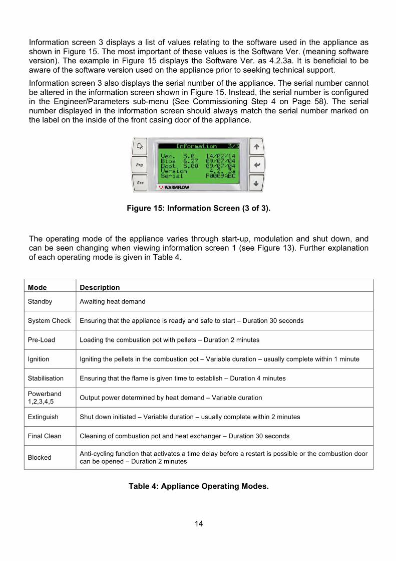
Information screen 3 displays a list of values relating to the software used in the appliance as shown in Figure 15. The most important of these values is the Software Ver. (meaning software version). The example in Figure 15 displays the Software Ver. as 4.2.3a. It is beneficial to be aware of the software version used on the appliance prior to seeking technical support. Information screen 3 also displays the serial number of the appliance. The serial number cannot be altered in the information screen shown in Figure 15. Instead, the serial number is configured in the Engineer/Parameters sub-menu (See Commissioning Step 4 on Page 58). The serial number displayed in the information screen should always match the serial number marked on the label on the inside of the front casing door of the appliance.
The operating mode of the appliance varies through start-up, modulation and shut down, and can be seen changing when viewing information screen 1 (see Figure 13). Further explanation of each operating mode is given in Table 4.
Mode Description
Standby Awaiting heat demand
System Check Ensuring that the appliance is ready and safe to start – Duration 30 seconds
Pre-Load Loading the combustion pot with pellets – Duration 2 minutes
Ignition Igniting the pellets in the combustion pot – Variable duration – usually complete within 1 minute
Stabilisation Ensuring that the flame is given time to establish – Duration 4 minutes
Powerband 1,2,3,4,5 Output power determined by heat demand – Variable duration
Extinguish Shut down initiated – Variable duration – usually complete within 2 minutes
Final Clean Cleaning of combustion pot and heat exchanger – Duration 30 seconds
Blocked Anti-cycling function that activates a time delay before a restart is possible or the combustion door can be opened – Duration 2 minutes
Table 4: Appliance Operating Modes.
Figure 15: Information Screen (3 of 3).
15
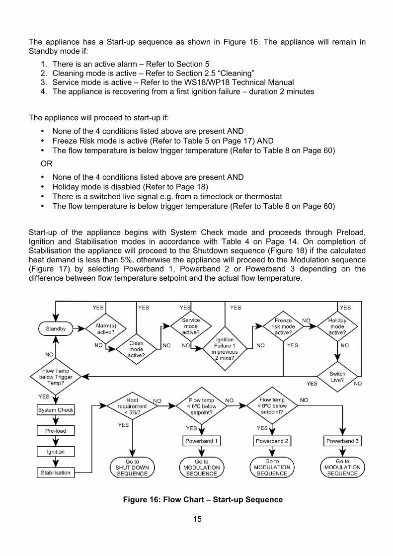
The appliance has a Start-up sequence as shown in Figure 16. The appliance will remain in Standby mode if:
1. There is an active alarm – Refer to Section 5 2. Cleaning mode is active – Refer to Section 2.5 “Cleaning” 3. Service mode is active – Refer to the WS18/WP18 Technical Manual 4. The appliance is recovering from a first ignition failure – duration 2 minutes
The appliance will proceed to start-up if:
• None of the 4 conditions listed above are present AND • Freeze Risk mode is active (Refer to Table 5 on Page 17) AND • The flow temperature is below trigger temperature (Refer to Table 8 on Page 60) OR
• None of the 4 conditions listed above are present AND • Holiday mode is disabled (Refer to Page 18) • There is a switched live signal e.g. from a timeclock or thermostat • The flow temperature is below trigger temperature (Refer to Table 8 on Page 60)
Start-up of the appliance begins with System Check mode and proceeds through Preload, Ignition and Stabilisation modes in accordance with Table 4 on Page 14. On completion of Stabilisation the appliance will proceed to the Shutdown sequence (Figure 18) if the calculated heat demand is less than 5%, otherwise the appliance will proceed to the Modulation sequence (Figure 17) by selecting Powerband 1, Powerband 2 or Powerband 3 depending on the difference between flow temperature setpoint and the actual flow temperature.
Figure 16: Flow Chart – Start-up Sequence
16
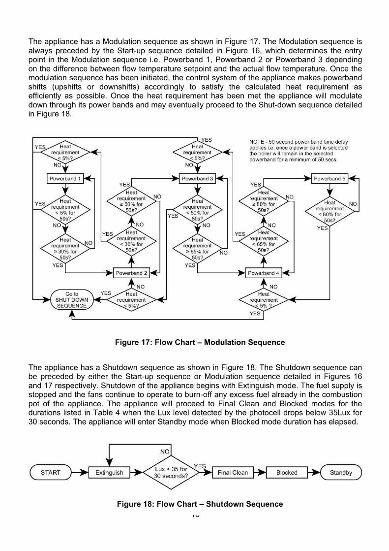
The appliance has a Modulation sequence as shown in Figure 17. The Modulation sequence is always preceded by the Start-up sequence detailed in Figure 16, which determines the entry point in the Modulation sequence i.e. Powerband 1, Powerband 2 or Powerband 3 depending on the difference between flow temperature setpoint and the actual flow temperature. Once the modulation sequence has been initiated, the control system of the appliance makes powerband shifts (upshifts or downshifts) accordingly to satisfy the calculated heat requirement as efficiently as possible. Once the heat requirement has been met the appliance will modulate down through its power bands and may eventually proceed to the Shut-down sequence detailed in Figure 18.
The appliance has a Shutdown sequence as shown in Figure 18. The Shutdown sequence can be preceded by either the Start-up sequence or Modulation sequence detailed in Figures 16 and 17 respectively. Shutdown of the appliance begins with Extinguish mode. The fuel supply is stopped and the fans continue to operate to burn-off any excess fuel already in the combustion pot of the appliance. The appliance will proceed to Final Clean and Blocked modes for the durations listed in Table 4 when the Lux level detected by the photocell drops below 35Lux for 30 seconds. The appliance will enter Standby mode when Blocked mode duration has elapsed.
Figure 17: Flow Chart – Modulation Sequence
Figure 18: Flow Chart – Shutdown Sequence
17
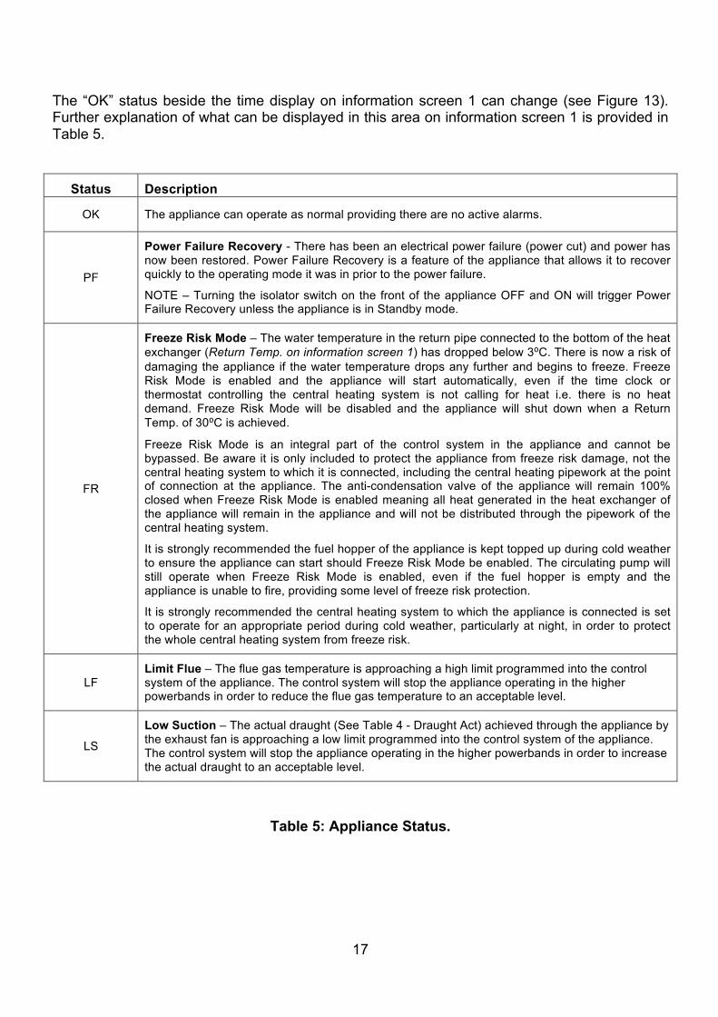
The “OK” status beside the time display on information screen 1 can change (see Figure 13). Further explanation of what can be displayed in this area on information screen 1 is provided in Table 5.
Status Description
OK The appliance can operate as normal providing there are no active alarms.
PF
Power Failure Recovery - There has been an electrical power failure (power cut) and power has now been restored. Power Failure Recovery is a feature of the appliance that allows it to recover quickly to the operating mode it was in prior to the power failure.
NOTE – Turning the isolator switch on the front of the appliance OFF and ON will trigger Power Failure Recovery unless the appliance is in Standby mode.
FR
Freeze Risk Mode – The water temperature in the return pipe connected to the bottom of the heat exchanger (Return Temp. on information screen 1) has dropped below 3⁰C. There is now a risk of damaging the appliance if the water temperature drops any further and begins to freeze. Freeze Risk Mode is enabled and the appliance will start automatically, even if the time clock or thermostat controlling the central heating system is not calling for heat i.e. there is no heat demand. Freeze Risk Mode will be disabled and the appliance will shut down when a Return Temp. of 30⁰C is achieved.
Freeze Risk Mode is an integral part of the control system in the appliance and cannot be bypassed. Be aware it is only included to protect the appliance from freeze risk damage, not the central heating system to which it is connected, including the central heating pipework at the point of connection at the appliance. The anti-condensation valve of the appliance will remain 100% closed when Freeze Risk Mode is enabled meaning all heat generated in the heat exchanger of the appliance will remain in the appliance and will not be distributed through the pipework of the central heating system.
It is strongly recommended the fuel hopper of the appliance is kept topped up during cold weather to ensure the appliance can start should Freeze Risk Mode be enabled. The circulating pump will still operate when Freeze Risk Mode is enabled, even if the fuel hopper is empty and the appliance is unable to fire, providing some level of freeze risk protection.
It is strongly recommended the central heating system to which the appliance is connected is set to operate for an appropriate period during cold weather, particularly at night, in order to protect the whole central heating system from freeze risk.
LF Limit Flue – The flue gas temperature is approaching a high limit programmed into the control system of the appliance. The control system will stop the appliance operating in the higher powerbands in order to reduce the flue gas temperature to an acceptable level.
LS
Low Suction – The actual draught (See Table 4 - Draught Act) achieved through the appliance by the exhaust fan is approaching a low limit programmed into the control system of the appliance. The control system will stop the appliance operating in the higher powerbands in order to increase the actual draught to an acceptable level.
Table 5: Appliance Status.
18
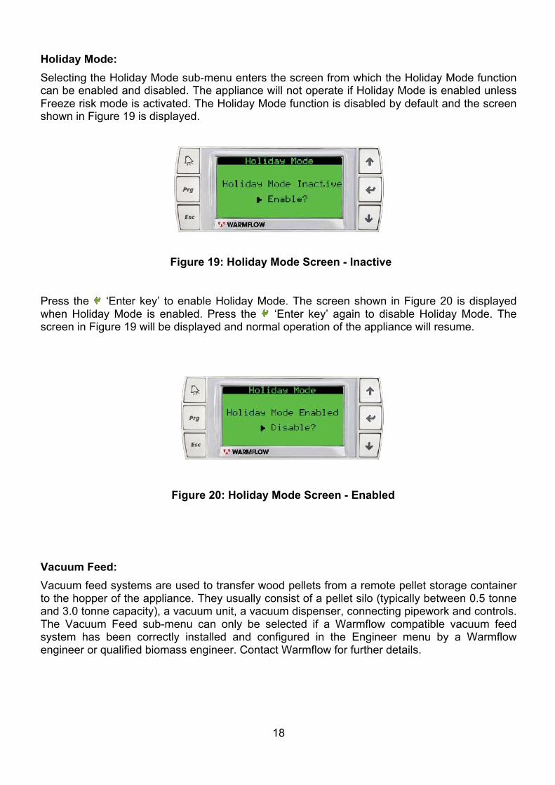
Holiday Mode: Selecting the Holiday Mode sub-menu enters the screen from which the Holiday Mode function can be enabled and disabled. The appliance will not operate if Holiday Mode is enabled unless Freeze risk mode is activated. The Holiday Mode function is disabled by default and the screen shown in Figure 19 is displayed.
Press the ‘Enter key’ to enable Holiday Mode. The screen shown in Figure 20 is displayed when Holiday Mode is enabled. Press the ‘Enter key’ again to disable Holiday Mode. The screen in Figure 19 will be displayed and normal operation of the appliance will resume.
Vacuum Feed: Vacuum feed systems are used to transfer wood pellets from a remote pellet storage container to the hopper of the appliance. They usually consist of a pellet silo (typically between 0.5 tonne and 3.0 tonne capacity), a vacuum unit, a vacuum dispenser, connecting pipework and controls. The Vacuum Feed sub-menu can only be selected if a Warmflow compatible vacuum feed system has been correctly installed and configured in the Engineer menu by a Warmflow engineer or qualified biomass engineer. Contact Warmflow for further details.
Figure 20: Holiday Mode Screen - Enabled
Figure 19: Holiday Mode Screen - Inactive
19
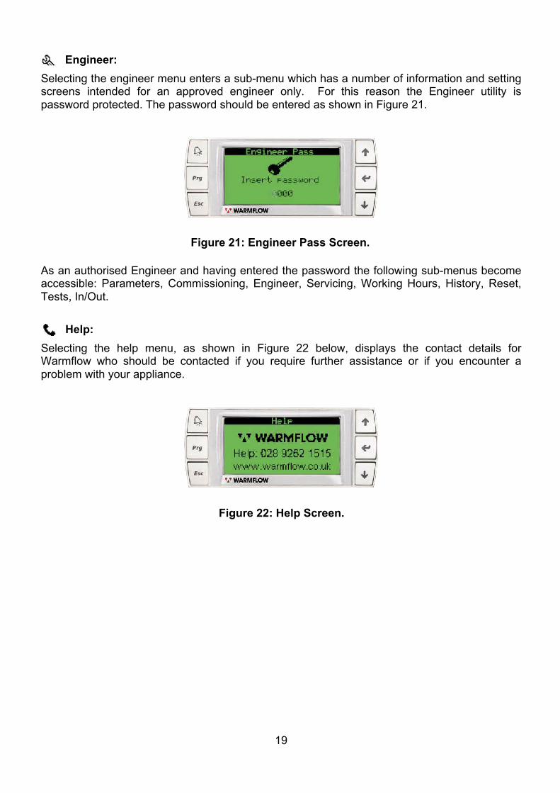
Engineer: Selecting the engineer menu enters a sub-menu which has a number of information and setting screens intended for an approved engineer only. For this reason the Engineer utility is password protected. The password should be entered as shown in Figure 21.
As an authorised Engineer and having entered the password the following sub-menus become accessible: Parameters, Commissioning, Engineer, Servicing, Working Hours, History, Reset, Tests, In/Out.
Help: Selecting the help menu, as shown in Figure 22 below, displays the contact details for Warmflow who should be contacted if you require further assistance or if you encounter a problem with your appliance.
Figure 22: Help Screen.
Figure 21: Engineer Pass Screen.
20
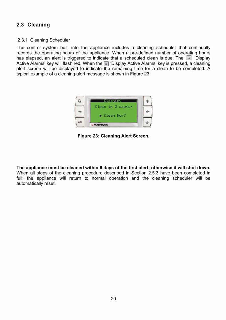
2.3 Cleaning 2.3.1 Cleaning Scheduler The control system built into the appliance includes a cleaning scheduler that continually records the operating hours of the appliance. When a pre-defined number of operating hours has elapsed, an alert is triggered to indicate that a scheduled clean is due. The ‘Display Active Alarms’ key will flash red. When the ‘Display Active Alarms’ key is pressed, a cleaning alert screen will be displayed to indicate the remaining time for a clean to be completed. A typical example of a cleaning alert message is shown in Figure 23.
The appliance must be cleaned within 6 days of the first alert; otherwise it will shut down. When all steps of the cleaning procedure described in Section 2.5.3 have been completed in full, the appliance will return to normal operation and the cleaning scheduler will be automatically reset.
Figure 23: Cleaning Alert Screen.
21
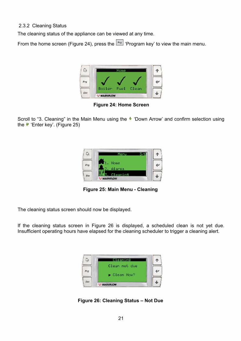
2.3.2 Cleaning Status The cleaning status of the appliance can be viewed at any time.
From the home screen (Figure 24), press the ‘Program key’ to view the main menu.
Scroll to “3. Cleaning” in the Main Menu using the ‘Down Arrow’ and confirm selection using the ‘Enter key’. (Figure 25)
The cleaning status screen should now be displayed. If the cleaning status screen in Figure 26 is displayed, a scheduled clean is not yet due. Insufficient operating hours have elapsed for the cleaning scheduler to trigger a cleaning alert.
Figure 24: Home Screen
Figure 25: Main Menu - Cleaning
Figure 26: Cleaning Status – Not Due
22
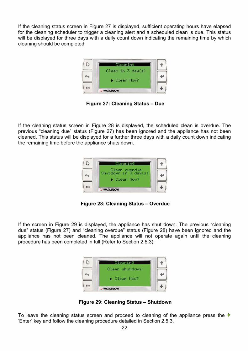
If the cleaning status screen in Figure 27 is displayed, sufficient operating hours have elapsed for the cleaning scheduler to trigger a cleaning alert and a scheduled clean is due. This status will be displayed for three days with a daily count down indicating the remaining time by which cleaning should be completed.
If the cleaning status screen in Figure 28 is displayed, the scheduled clean is overdue. The previous “cleaning due” status (Figure 27) has been ignored and the appliance has not been cleaned. This status will be displayed for a further three days with a daily count down indicating the remaining time before the appliance shuts down.
If the screen in Figure 29 is displayed, the appliance has shut down. The previous “cleaning due” status (Figure 27) and “cleaning overdue” status (Figure 28) have been ignored and the appliance has not been cleaned. The appliance will not operate again until the cleaning procedure has been completed in full (Refer to Section 2.5.3).
To leave the cleaning status screen and proceed to cleaning of the appliance press the ‘Enter’ key and follow the cleaning procedure detailed in Section 2.5.3.
Figure 27: Cleaning Status – Due
Figure 28: Cleaning Status – Overdue
Figure 29: Cleaning Status – Shutdown
23
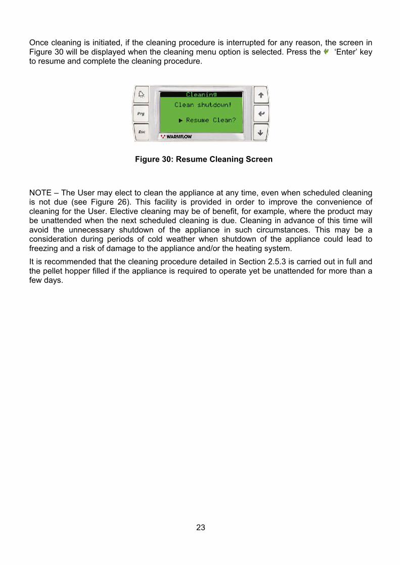
Once cleaning is initiated, if the cleaning procedure is interrupted for any reason, the screen in Figure 30 will be displayed when the cleaning menu option is selected. Press the ‘Enter’ key to resume and complete the cleaning procedure.
NOTE – The User may elect to clean the appliance at any time, even when scheduled cleaning is not due (see Figure 26). This facility is provided in order to improve the convenience of cleaning for the User. Elective cleaning may be of benefit, for example, where the product may be unattended when the next scheduled cleaning is due. Cleaning in advance of this time will avoid the unnecessary shutdown of the appliance in such circumstances. This may be a consideration during periods of cold weather when shutdown of the appliance could lead to freezing and a risk of damage to the appliance and/or the heating system. It is recommended that the cleaning procedure detailed in Section 2.5.3 is carried out in full and the pellet hopper filled if the appliance is required to operate yet be unattended for more than a few days.
Figure 30: Resume Cleaning Screen
24
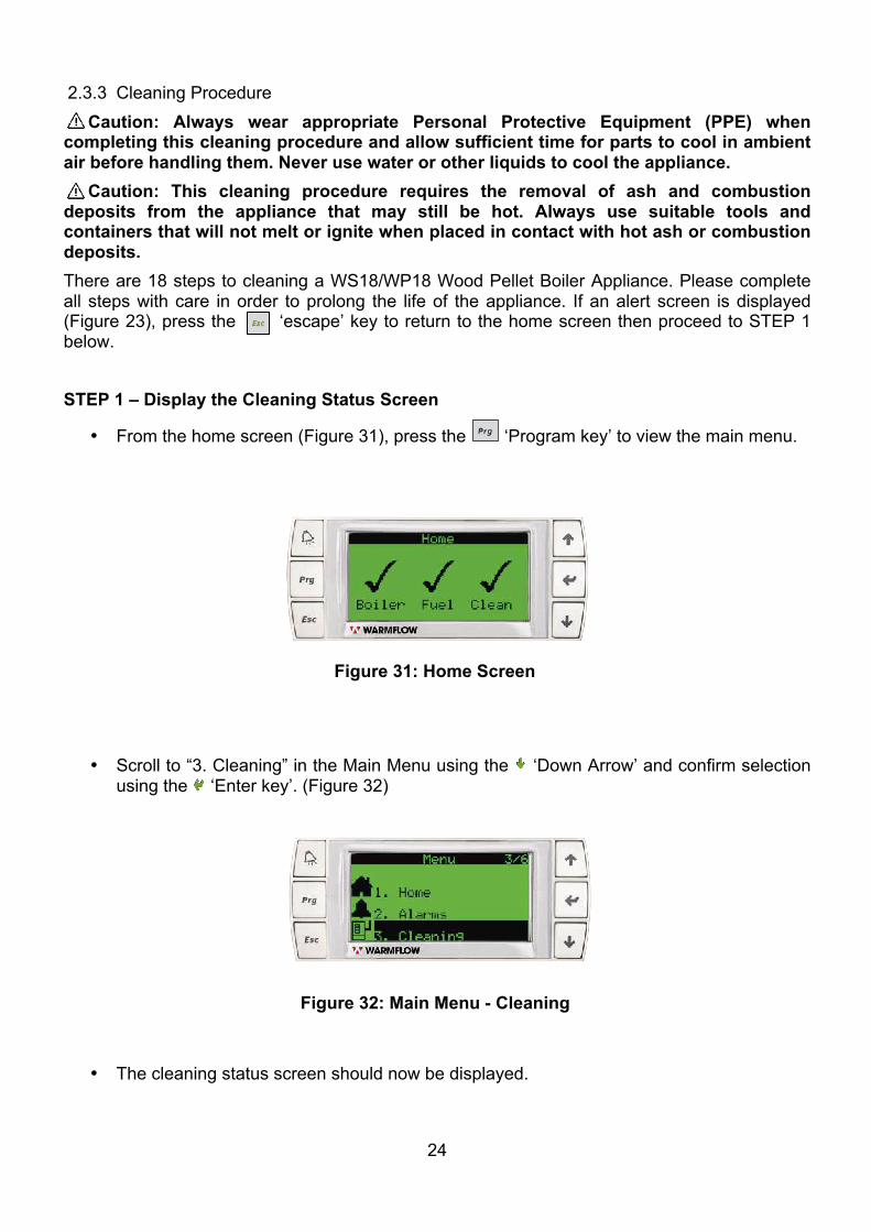
2.3.3 Cleaning Procedure Caution: Always wear appropriate Personal Protective Equipment (PPE) when completing this cleaning procedure and allow sufficient time for parts to cool in ambient air before handling them. Never use water or other liquids to cool the appliance. Caution: This cleaning procedure requires the removal of ash and combustion deposits from the appliance that may still be hot. Always use suitable tools and containers that will not melt or ignite when placed in contact with hot ash or combustion deposits. There are 18 steps to cleaning a WS18/WP18 Wood Pellet Boiler Appliance. Please complete all steps with care in order to prolong the life of the appliance. If an alert screen is displayed (Figure 23), press the ‘escape’ key to return to the home screen then proceed to STEP 1 below. STEP 1 – Display the Cleaning Status Screen
• From the home screen (Figure 31), press the ‘Program key’ to view the main menu.
• Scroll to “3. Cleaning” in the Main Menu using the ‘Down Arrow’ and confirm selection using the ‘Enter key’. (Figure 32)
• The cleaning status screen should now be displayed.
Figure 31: Home Screen
Figure 32: Main Menu - Cleaning
25
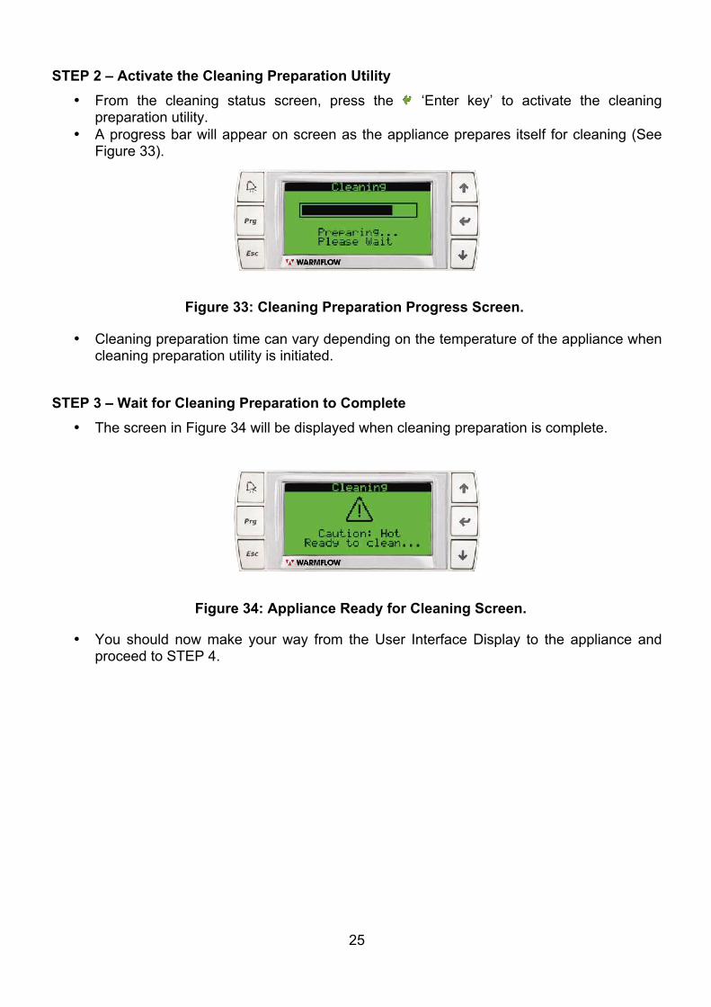
STEP 2 – Activate the Cleaning Preparation Utility • From the cleaning status screen, press the ‘Enter key’ to activate the cleaning
preparation utility. • A progress bar will appear on screen as the appliance prepares itself for cleaning (See
Figure 33).
• Cleaning preparation time can vary depending on the temperature of the appliance when cleaning preparation utility is initiated.
STEP 3 – Wait for Cleaning Preparation to Complete
• The screen in Figure 34 will be displayed when cleaning preparation is complete.
• You should now make your way from the User Interface Display to the appliance and proceed to STEP 4.
Figure 33: Cleaning Preparation Progress Screen.
Figure 34: Appliance Ready for Cleaning Screen.
26
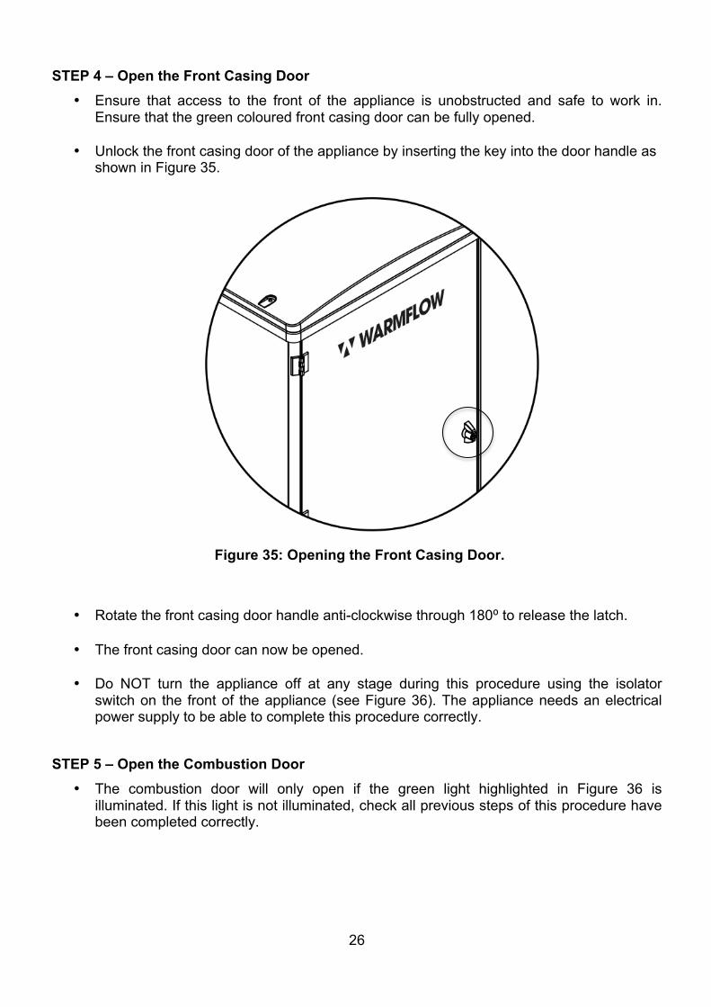
STEP 4 – Open the Front Casing Door • Ensure that access to the front of the appliance is unobstructed and safe to work in.
Ensure that the green coloured front casing door can be fully opened.
• Unlock the front casing door of the appliance by inserting the key into the door handle as shown in Figure 35.
• Rotate the front casing door handle anti-clockwise through 180⁰ to release the latch.
• The front casing door can now be opened.
• Do NOT turn the appliance off at any stage during this procedure using the isolator switch on the front of the appliance (see Figure 36). The appliance needs an electrical power supply to be able to complete this procedure correctly.
STEP 5 – Open the Combustion Door
• The combustion door will only open if the green light highlighted in Figure 36 is illuminated. If this light is not illuminated, check all previous steps of this procedure have been completed correctly.
Figure 35: Opening the Front Casing Door.
27
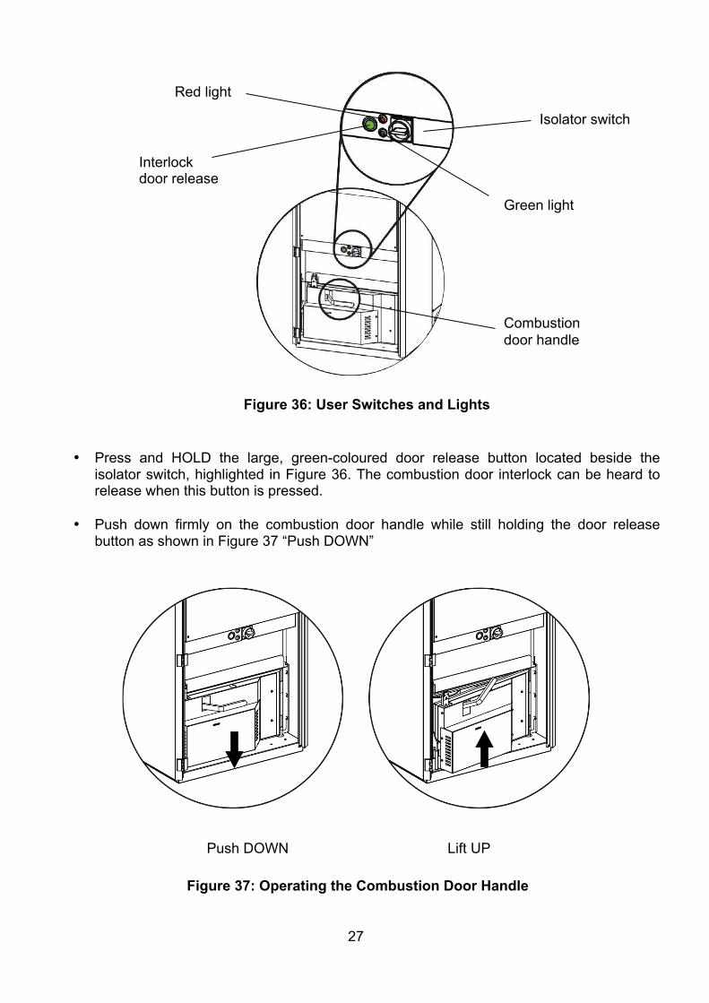
• Press and HOLD the large, green-coloured door release button located beside the isolator switch, highlighted in Figure 36. The combustion door interlock can be heard to release when this button is pressed.
• Push down firmly on the combustion door handle while still holding the door release button as shown in Figure 37 “Push DOWN”
Push DOWN Lift UP
Figure 36: User Switches and Lights
Figure 37: Operating the Combustion Door Handle
Red light
Interlock door release
Isolator switch
Green light
Combustion door handle
28
• Lift the combustion door handle up while still holding the door release button as shown in Figure 37 “Lift UP”.
• The combustion door can now be opened and the door release button can be released. Leave the combustion door handle fully up until STEP 16.
• The “Combustion door OPEN” alarm will be activated on the user control interface when the combustion door is opened. Do not attempt to clear this alarm whilst the cleaning procedure is in progress. The “Combustion door OPEN” alarm will clear automatically when all steps of this cleaning procedure are complete.
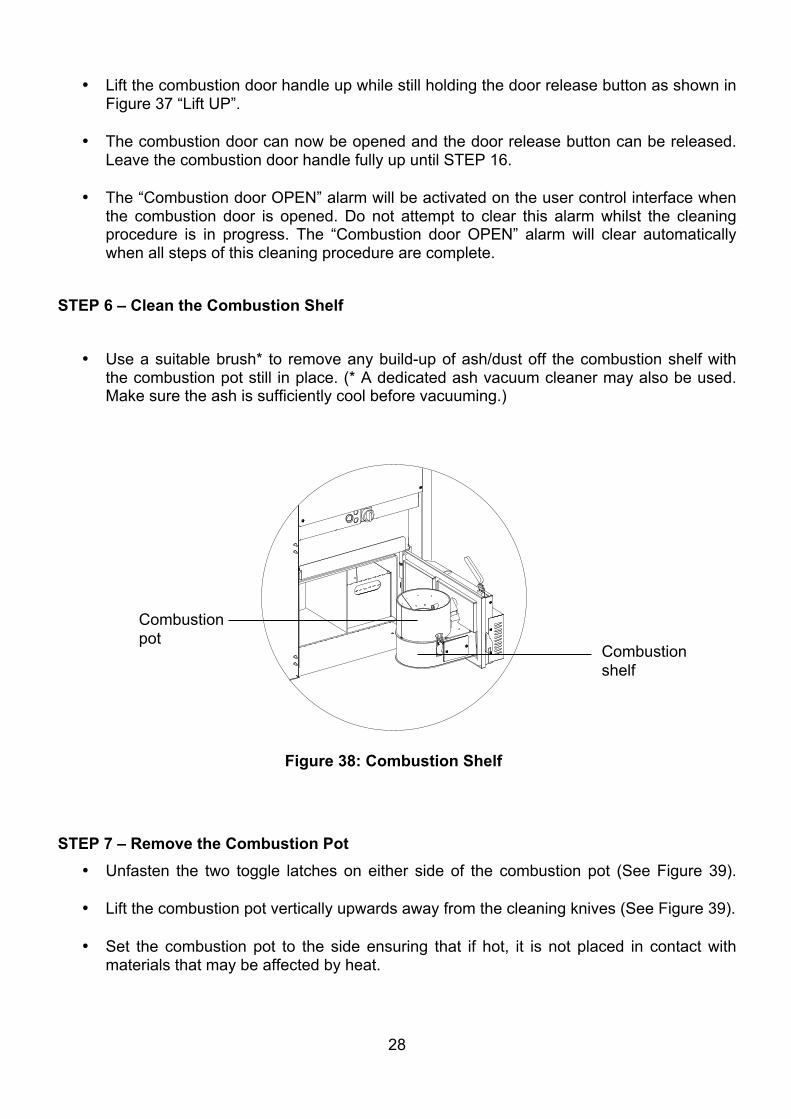
STEP 6 – Clean the Combustion Shelf
• Use a suitable brush* to remove any build-up of ash/dust off the combustion shelf with the combustion pot still in place. (* A dedicated ash vacuum cleaner may also be used. Make sure the ash is sufficiently cool before vacuuming.)
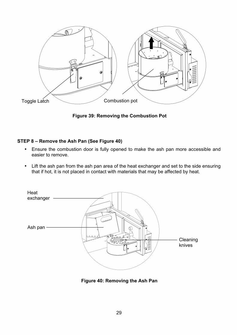
STEP 7 – Remove the Combustion Pot
• Unfasten the two toggle latches on either side of the combustion pot (See Figure 39).
• Lift the combustion pot vertically upwards away from the cleaning knives (See Figure 39).
• Set the combustion pot to the side ensuring that if hot, it is not placed in contact with materials that may be affected by heat.
Figure 38: Combustion Shelf
Combustion shelf
Combustion pot
29
STEP 8 – Remove the Ash Pan (See Figure 40)
• Ensure the combustion door is fully opened to make the ash pan more accessible and easier to remove.
• Lift the ash pan from the ash pan area of the heat exchanger and set to the side ensuring that if hot, it is not placed in contact with materials that may be affected by heat.
Figure 40: Removing the Ash Pan
Figure 39: Removing the Combustion Pot
Combustion pot
Ash pan
Cleaning knives
Heat exchanger
Toggle Latch
30
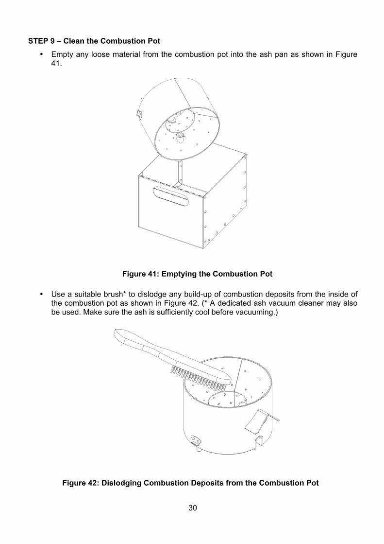
STEP 9 – Clean the Combustion Pot • Empty any loose material from the combustion pot into the ash pan as shown in Figure
41.
• Use a suitable brush* to dislodge any build-up of combustion deposits from the inside of the combustion pot as shown in Figure 42. (* A dedicated ash vacuum cleaner may also be used. Make sure the ash is sufficiently cool before vacuuming.)
Figure 41: Emptying the Combustion Pot
Figure 42: Dislodging Combustion Deposits from the Combustion Pot
31
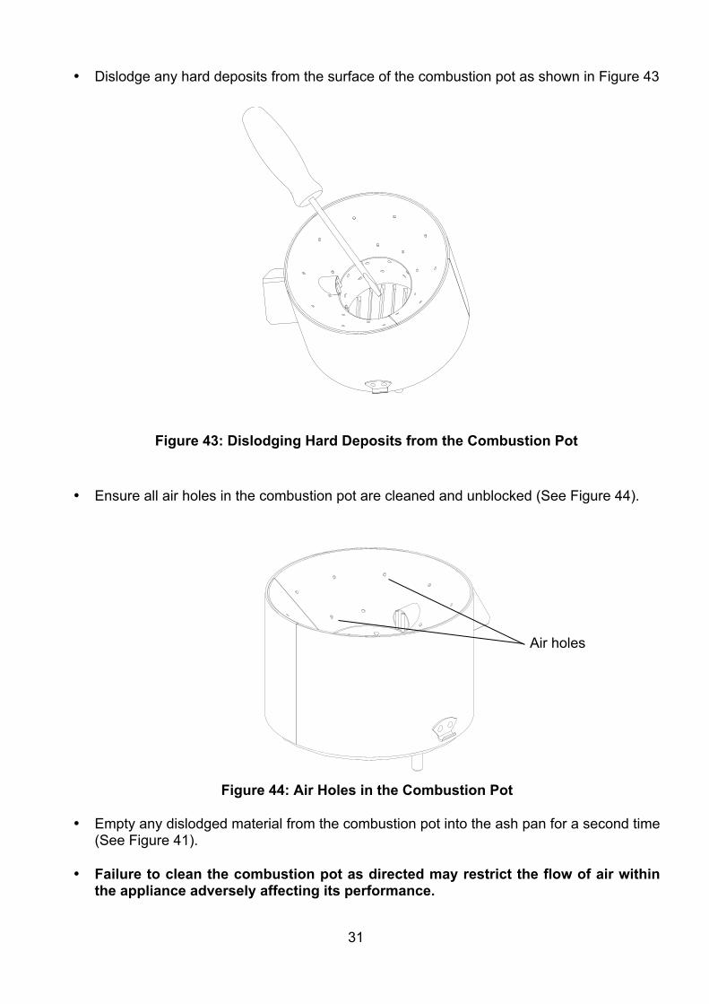
• Dislodge any hard deposits from the surface of the combustion pot as shown in Figure 43
• Ensure all air holes in the combustion pot are cleaned and unblocked (See Figure 44).
• Empty any dislodged material from the combustion pot into the ash pan for a second time (See Figure 41).
• Failure to clean the combustion pot as directed may restrict the flow of air within the appliance adversely affecting its performance.
Figure 43: Dislodging Hard Deposits from the Combustion Pot
Figure 44: Air Holes in the Combustion Pot
Air holes
32
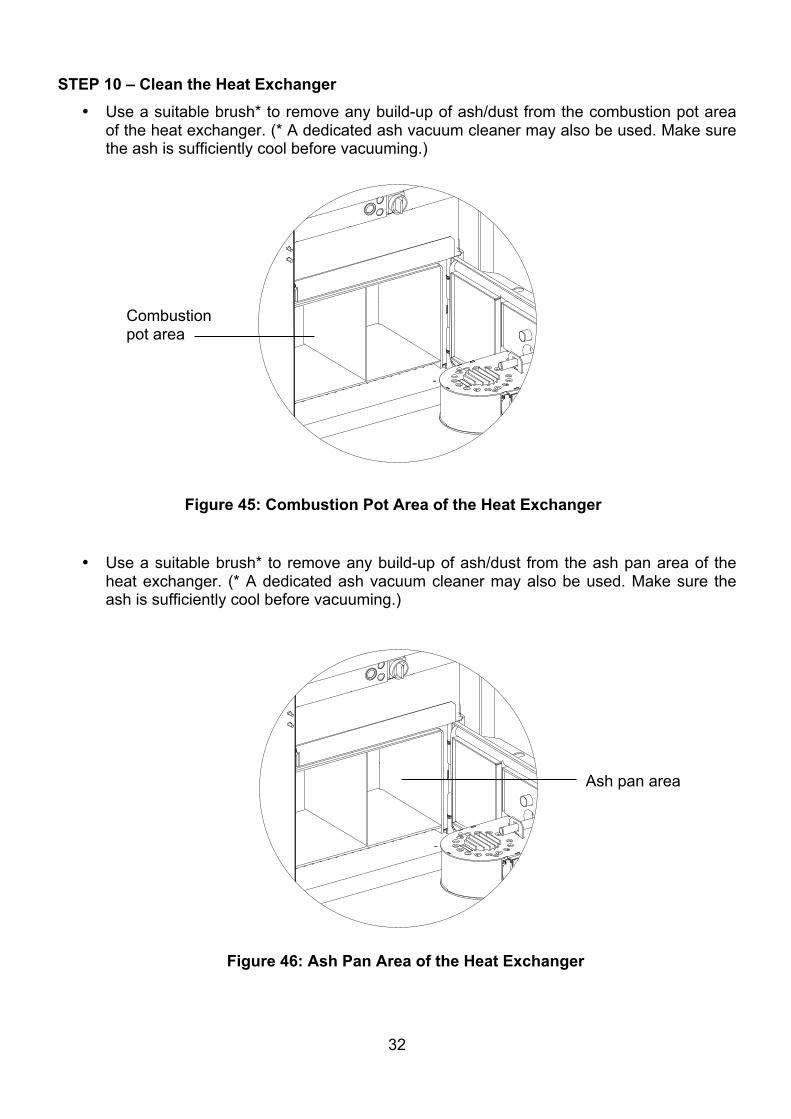
STEP 10 – Clean the Heat Exchanger • Use a suitable brush* to remove any build-up of ash/dust from the combustion pot area
of the heat exchanger. (* A dedicated ash vacuum cleaner may also be used. Make sure the ash is sufficiently cool before vacuuming.)
• Use a suitable brush* to remove any build-up of ash/dust from the ash pan area of the
heat exchanger. (* A dedicated ash vacuum cleaner may also be used. Make sure the ash is sufficiently cool before vacuuming.)
Figure 45: Combustion Pot Area of the Heat Exchanger
Figure 46: Ash Pan Area of the Heat Exchanger
Combustion pot area
Ash pan area
33
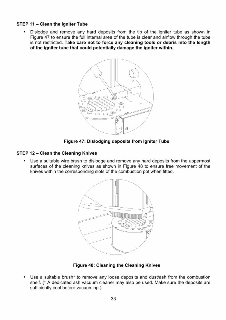
STEP 11 – Clean the Igniter Tube
• Dislodge and remove any hard deposits from the tip of the igniter tube as shown in Figure 47 to ensure the full internal area of the tube is clear and airflow through the tube is not restricted. Take care not to force any cleaning tools or debris into the length of the igniter tube that could potentially damage the igniter within.
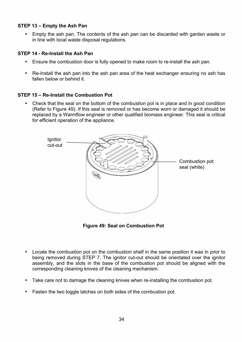
STEP 12 – Clean the Cleaning Knives
• Use a suitable wire brush to dislodge and remove any hard deposits from the uppermost surfaces of the cleaning knives as shown in Figure 48 to ensure free movement of the knives within the corresponding slots of the combustion pot when fitted.
• Use a suitable brush* to remove any loose deposits and dust/ash from the combustion shelf. (* A dedicated ash vacuum cleaner may also be used. Make sure the deposits are sufficiently cool before vacuuming.)
Figure 47: Dislodging deposits from Igniter Tube
Figure 48: Cleaning the Cleaning Knives
34
STEP 13 – Empty the Ash Pan • Empty the ash pan. The contents of the ash pan can be discarded with garden waste or
in line with local waste disposal regulations.
STEP 14 - Re-Install the Ash Pan
• Ensure the combustion door is fully opened to make room to re-install the ash pan.
• Re-Install the ash pan into the ash pan area of the heat exchanger ensuring no ash has fallen below or behind it.
STEP 15 – Re-Install the Combustion Pot
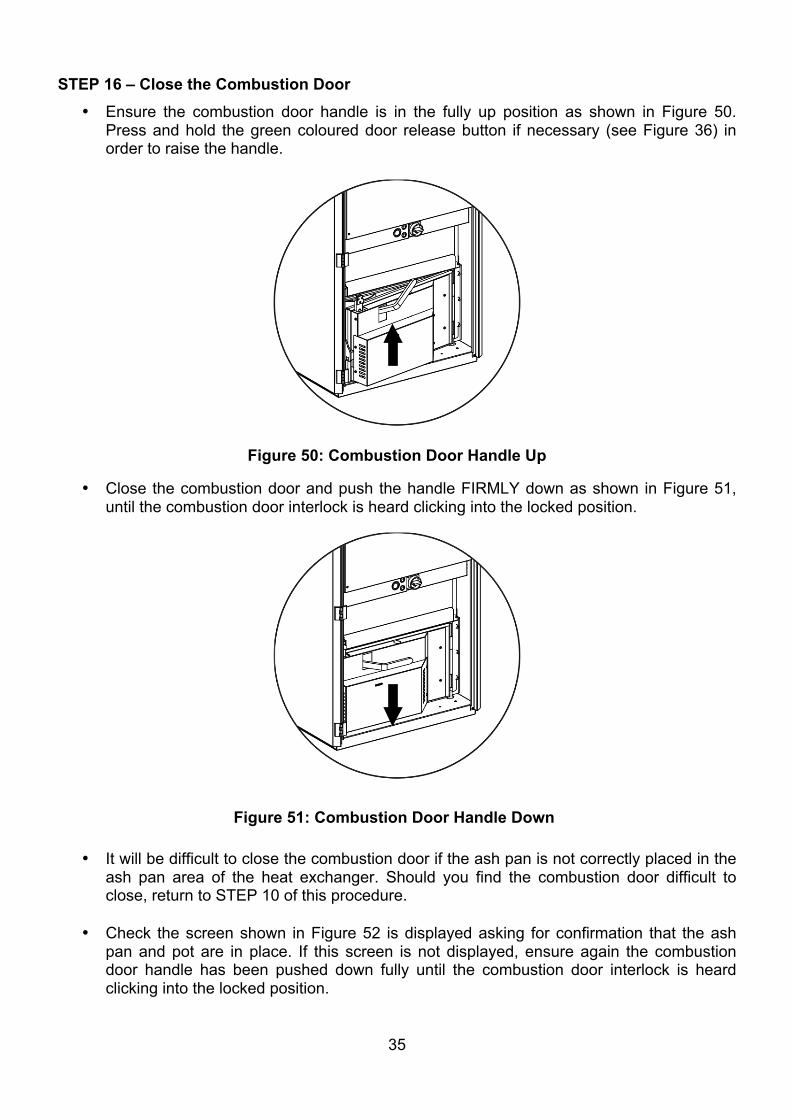
• Check that the seal on the bottom of the combustion pot is in place and in good condition (Refer to Figure 49). If this seal is removed or has become worn or damaged it should be replaced by a Warmflow engineer or other qualified biomass engineer. This seal is critical for efficient operation of the appliance.
• Locate the combustion pot on the combustion shelf in the same position it was in prior to being removed during STEP 7. The ignitor cut-out should be orientated over the ignitor assembly, and the slots in the base of the combustion pot should be aligned with the corresponding cleaning knives of the cleaning mechanism.
• Take care not to damage the cleaning knives when re-installing the combustion pot.
• Fasten the two toggle latches on both sides of the combustion pot.
Figure 49: Seal on Combustion Pot
Combustion pot seal (white)
Ignitor cut-out
35
STEP 16 – Close the Combustion Door • Ensure the combustion door handle is in the fully up position as shown in Figure 50.
Press and hold the green coloured door release button if necessary (see Figure 36) in order to raise the handle.
• Close the combustion door and push the handle FIRMLY down as shown in Figure 51, until the combustion door interlock is heard clicking into the locked position.
• It will be difficult to close the combustion door if the ash pan is not correctly placed in the ash pan area of the heat exchanger. Should you find the combustion door difficult to close, return to STEP 10 of this procedure.
• Check the screen shown in Figure 52 is displayed asking for confirmation that the ash pan and pot are in place. If this screen is not displayed, ensure again the combustion door handle has been pushed down fully until the combustion door interlock is heard clicking into the locked position.
Figure 50: Combustion Door Handle Up
Figure 51: Combustion Door Handle Down
36
STEP 17 – Close the Front Casing Door • Close the front casing door and rotate the door handle clockwise through 180⁰ to engage
the latch.
• Lock the front casing door of the appliance using the key provided.
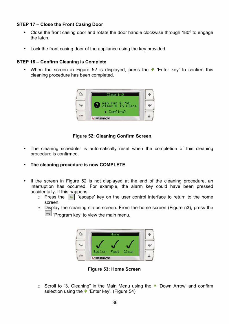
STEP 18 – Confirm Cleaning is Complete • When the screen in Figure 52 is displayed, press the ‘Enter key’ to confirm this
cleaning procedure has been completed.
• The cleaning scheduler is automatically reset when the completion of this cleaning
procedure is confirmed.
• The cleaning procedure is now COMPLETE.
• If the screen in Figure 52 is not displayed at the end of the cleaning procedure, an interruption has occurred. For example, the alarm key could have been pressed accidentally. If this happens:
o Press the ‘escape’ key on the user control interface to return to the home screen.
o Display the cleaning status screen. From the home screen (Figure 53), press the ‘Program key’ to view the main menu.
o Scroll to “3. Cleaning” in the Main Menu using the ‘Down Arrow’ and confirm
selection using the ‘Enter key’. (Figure 54)
Figure 52: Cleaning Confirm Screen.
Figure 53: Home Screen
37
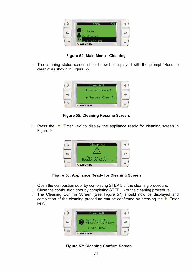
o The cleaning status screen should now be displayed with the prompt “Resume clean?” as shown in Figure 55.
o Press the ‘Enter key’ to display the appliance ready for cleaning screen in Figure 56.
o Open the combustion door by completing STEP 5 of the cleaning procedure. o Close the combustion door by completing STEP 16 of the cleaning procedure. o The Cleaning Confirm Screen (See Figure 57) should now be displayed and
completion of the cleaning procedure can be confirmed by pressing the ‘Enter key’.
Figure 55: Cleaning Resume Screen.
Figure 56: Appliance Ready for Cleaning Screen
Figure 54: Main Menu - Cleaning
Figure 57: Cleaning Confirm Screen
38
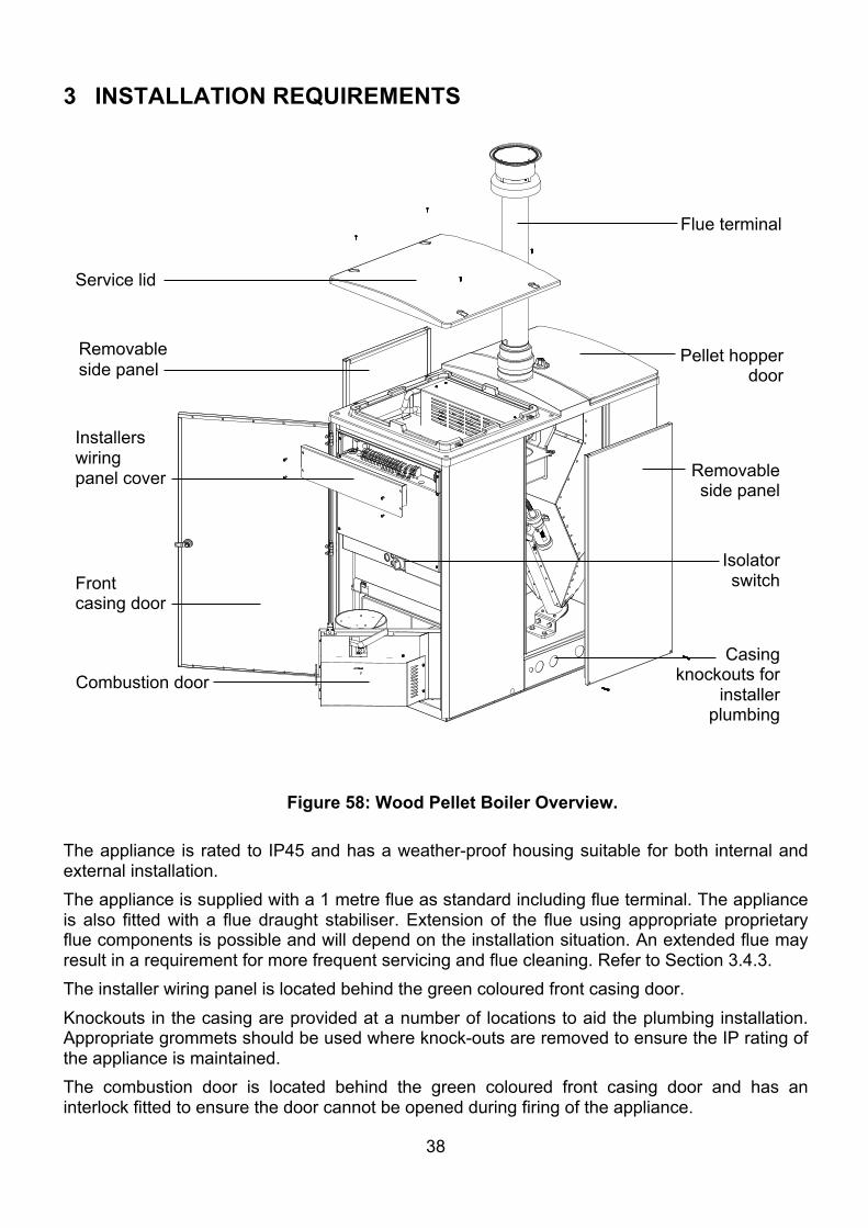
3 INSTALLATION REQUIREMENTS
The appliance is rated to IP45 and has a weather-proof housing suitable for both internal and external installation. The appliance is supplied with a 1 metre flue as standard including flue terminal. The appliance is also fitted with a flue draught stabiliser. Extension of the flue using appropriate proprietary flue components is possible and will depend on the installation situation. An extended flue may result in a requirement for more frequent servicing and flue cleaning. Refer to Section 3.4.3. The installer wiring panel is located behind the green coloured front casing door. Knockouts in the casing are provided at a number of locations to aid the plumbing installation. Appropriate grommets should be used where knock-outs are removed to ensure the IP rating of the appliance is maintained. The combustion door is located behind the green coloured front casing door and has an interlock fitted to ensure the door cannot be opened during firing of the appliance.
Figure 58: Wood Pellet Boiler Overview.
Isolator switch
Pellet hopper door
Combustion door
Front casing door
Flue terminal
Installers wiring panel cover
Service lid
Removable side panel
Removable side panel
Casing knockouts for
installer plumbing
39
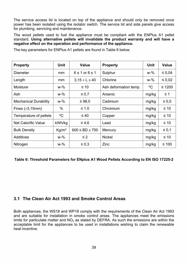
The service access lid is located on top of the appliance and should only be removed once power has been isolated using the isolator switch. The service lid and side panels give access for plumbing, servicing and maintenance. The wood pellets used to fuel the appliance must be compliant with the ENPlus A1 pellet standard. Using alternative pellets will invalidate the product warranty and will have a negative effect on the operation and performance of the appliance. The key parameters for ENPlus A1 pellets are found in Table 6 below.
Property Unit Value Property Unit Value
Diameter mm 6 ± 1 or 8 ± 1 Sulphur w-% ≤ 0,04
Length mm 3,15 ˂ L ≤ 40 Chlorine w-% ≤ 0,02
Moisture w-% ≤ 10 Ash deformation temp. ⁰C ≥ 1200
Ash w-% ≤ 0.7 Arsenic mg/kg ≤ 1
Mechanical Durability w-% ≥ 98,0 Cadmium mg/kg ≤ 0,5
Fines (˂3,15mm) % ≤ 1.0 Chromium mg/kg ≤ 10
Temperature of pellets ⁰C ≤ 40 Copper mg/kg ≤ 10
Net Calorific Value kWh/kg ≥ 4,6 Lead mg/kg ≤ 10
Bulk Density Kg/m³ 600 ≤ BD ≤ 750 Mercury mg/kg ≤ 0,1
Additives w-% ≤ 2 Nickel mg/kg ≤ 10
Nitrogen w-% ≤ 0,3 Zinc mg/kg ≤ 100
Table 6: Threshold Parameters for ENplus A1 Wood Pellets According to EN ISO 17225-2
3.1 The Clean Air Act 1993 and Smoke Control Areas Both appliances, the WS18 and WP18 comply with the requirements of the Clean Air Act 1993 and are suitable for installation in smoke control areas. The appliances meet the emissions limits for particulate matter and NOx as stated by DEFRA. As such the emissions are within the acceptable limit for the appliances to be used in installations wishing to claim the renewable heat incentive.
40
Your local authority is responsible for implementing the Clean Air Act 1993 including designation and supervision of smoke control areas and you can contact them for details of Clean Air Act requirements. The installation must comply with regional Building Regulations. The maximum noise level generated by the appliance is well within the residential noise limitations and is similar to that of a high efficiency oil boiler. The appliance is secured on a wooden pallet for shipping. The appliance is fixed to this pallet using five screw fasteners through its base. Remove these screw fasteners before attempting to remove the appliance from the pallet. The screw fasteners can be accessed by opening the front casing door and both removable side panels (See Figure 58). 3.2 General Requirements 3.2.1 Transportation aids and hearth The appliance can be supplied with an optional WPTRK WP Install Buggy comprising of an axle, 2 wheels, support strap and fasteners. This optional WP install buggy must only be used on solid level surfaces. Details on how to assemble these items are below:
• Remove and retain the 1x grommet located along each lower side edge of the appliance. • Insert the axle through the now exposed holes. • Secure 1 wheel to each side of the boiler with the supplied washers on each side of each
wheel. • Insert the supplied R clips on each end of the axle to secure the wheels. • Remove and retain the grommet from the lower edge rear of the appliance. • Secure the support strap with the supplied bolt and washer.
The wheels and support strap can now be used to guide the appliance into the required location. Stand clear, and exercise caution following current manual handling regulations, as the appliance has a dry weight of 250kg. Once the appliance has been placed correctly, remove WP install buggy, and replace the grommets. The appliance has a hearth temperature of between 50°C and 85°C and should be placed on a level, rigid, non-porous, non-combustible base, which is not softened by heat, to comply with current local Building Regulations. Please refer to table 1 for product mass data. Ground fixings may be used if required – locations for securing the appliance to the shipping pallet can be used for this purpose. Ensure opening of the combustion door is not impeded by any fixings used.
41
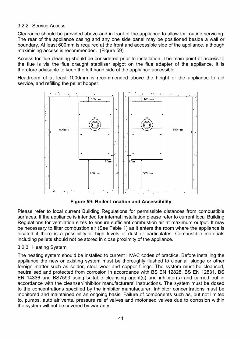
3.2.2 Service Access Clearance should be provided above and in front of the appliance to allow for routine servicing. The rear of the appliance casing and any one side panel may be positioned beside a wall or boundary. At least 600mm is required at the front and accessible side of the appliance, although maximising access is recommended. (Figure 59) Access for flue cleaning should be considered prior to installation. The main point of access to the flue is via the flue draught stabiliser spigot on the flue adapter of the appliance. It is therefore advisable to keep the left hand side of the appliance accessible. Headroom of at least 1000mm is recommended above the height of the appliance to aid service, and refilling the pellet hopper.
Please refer to local current Building Regulations for permissible distances from combustible surfaces. If the appliance is intended for internal installation please refer to current local Building Regulations for ventilation sizes to ensure sufficient combustion air at maximum output. It may be necessary to filter combustion air (See Table 1) as it enters the room where the appliance is located if there is a possibility of high levels of dust or particulates. Combustible materials including pellets should not be stored in close proximity of the appliance. 3.2.3 Heating System The heating system should be installed to current HVAC codes of practice. Before installing the appliance the new or existing system must be thoroughly flushed to clear all sludge or other foreign matter such as solder, steel wool and copper filings. The system must be cleansed, neutralised and protected from corrosion in accordance with BS EN 12828, BS EN 12831, BS EN 14336 and BS7593 using suitable cleansing agent(s) and inhibitor(s) and carried out in accordance with the cleanser/inhibitor manufacturers’ instructions. The system must be dosed to the concentrations specified by the inhibitor manufacturer. Inhibitor concentrations must be monitored and maintained on an ongoing basis. Failure of components such as, but not limited to, pumps, auto air vents, pressure relief valves and motorised valves due to corrosion within the system will not be covered by warranty.
Figure 59: Boiler Location and Accessibility
42
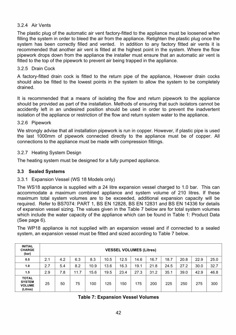
3.2.4 Air Vents The plastic plug of the automatic air vent factory-fitted to the appliance must be loosened when filling the system in order to bleed the air from the appliance. Retighten the plastic plug once the system has been correctly filled and vented. In addition to any factory fitted air vents it is recommended that another air vent is fitted at the highest point in the system. Where the flow pipework drops down from the appliance the installer must ensure that an automatic air vent is fitted to the top of the pipework to prevent air being trapped in the appliance. 3.2.5 Drain Cock A factory-fitted drain cock is fitted to the return pipe of the appliance, However drain cocks should also be fitted to the lowest points in the system to allow the system to be completely drained. It is recommended that a means of isolating the flow and return pipework to the appliance should be provided as part of the installation. Methods of ensuring that such isolators cannot be accidently left in an undesired position should be used in order to prevent the inadvertent isolation of the appliance or restriction of the flow and return system water to the appliance. 3.2.6 Pipework We strongly advise that all installation pipework is run in copper. However, if plastic pipe is used the last 1000mm of pipework connected directly to the appliance must be of copper. All connections to the appliance must be made with compression fittings. 3.2.7 Heating System Design The heating system must be designed for a fully pumped appliance. 3.3 Sealed Systems 3.3.1 Expansion Vessel (WS 18 Models only) The WS18 appliance is supplied with a 24 litre expansion vessel charged to 1.0 bar. This can accommodate a maximum combined appliance and system volume of 210 litres. If these maximum total system volumes are to be exceeded, additional expansion capacity will be required. Refer to BS7074: PART 1, BS EN 12828, BS EN 12831 and BS EN 14336 for details of expansion vessel sizing. The values given in the Table 7 below are for total system volumes which include the water capacity of the appliance which can be found in Table 1: Product Data (See page 6). The WP18 appliance is not supplied with an expansion vessel and if connected to a sealed system, an expansion vessel must be fitted and sized according to Table 7 below.
INITIAL CHARGE
(bar) VESSEL VOLUMES (Litres)
0.5 2.1 4.2 6.3 8.3 10.5 12.5 14.6 16.7 18.7 20.8 22.9 25.0 1.0 2.7 5.4 8.2 10.9 13.6 16.3 19.1 21.8 24.5 27.2 30.0 32.7 1.5 2.9 7.8 11.7 15.6 19.5 23.4 27.3 31.2 35.1 39.0 42.9 46.8
TOTAL SYSTEM VOLUME (Litres)
25 50 75 100 125 150 175 200 225 250 275 300
Table 7: Expansion Vessel Volumes
43
When measuring the expansion vessel bladder pre-charge pressure, using a tyre pressure gauge, the system must be cold (less than 25°C) and the system pressure must be relieved (by manually operating the system pressure relief valve) in order to obtain an accurate reading.
3.4 System Filling After the system has been properly filled the pressure gauge should read 1 bar when the system is cold. The valve must be fully closed and the flexible filling loop removed from the valve in accordance with building regulations. Expect a small water loss from the pipe. 3.4.1 System Filling For the WS18 appliance a filling point complete with a filling loop is supplied fitted to the expansion vessel. The filling loop must be disconnected from the mains supply after filling. A system pressure when cold of 1 bar is recommended. After filling, vent all air from the system. The plastic plugs of the auto air vent(s) factory fitted to the appliance must be loosened when filling the system in order to bleed the air from the appliance, and retightened when system filling and venting has been completed. 3.4.2 System Pressure (WS 18 only) Water loss from the system is indicated by a reduction in pressure on the pressure gauge. In the first week of operation it is normal to see a drop in system pressure. After this time the system pressure must be rechecked and the system refilled. Failure to do so may lead to appliance faults. The system pressure should be checked periodically by means of the pressure gauge at the expansion vessel. The WS18 appliance comes complete with an integrated expansion vessel, pressure gauge and filling loop. The minimum pressure, as indicated by the black needle, must not be less than 0.5 bar when the appliance is cold and typically around 2.5 bar when the appliance is at normal operating temperature. If the pressure is outside this range contact your installer. Frequent or routine refilling and topping up of the system should not be necessary on an ongoing basis and may prove harmful to the appliance. Should topping up prove necessary on a frequent or routine basis you must contact your installer. Special attention must be given to the concentration of corrosion inhibitors in the system water where there is a need for topping up or refilling. Inhibitor concentrations must be restored to the concentrations specified by the inhibitor manufacturer. 3.4.3 Pressure Relief Valve All models are fitted with a 3 bar pressure relief valve. The pressure relief valve must be able to discharge externally to a drain where the discharge can be seen, and cannot cause any injury or damage. No other valves should be positioned between the relief valve and discharge termination.
3.4.4 Low Pressure Switch Where there is a significant loss of water from the system the appliance thermostats may fail to operate which would result in serious damage to the appliance. To prevent this, a low pressure cut out switch set at 0.5 bar is fitted to the appliance. The switch will automatically reset when the pressure is restored.
44
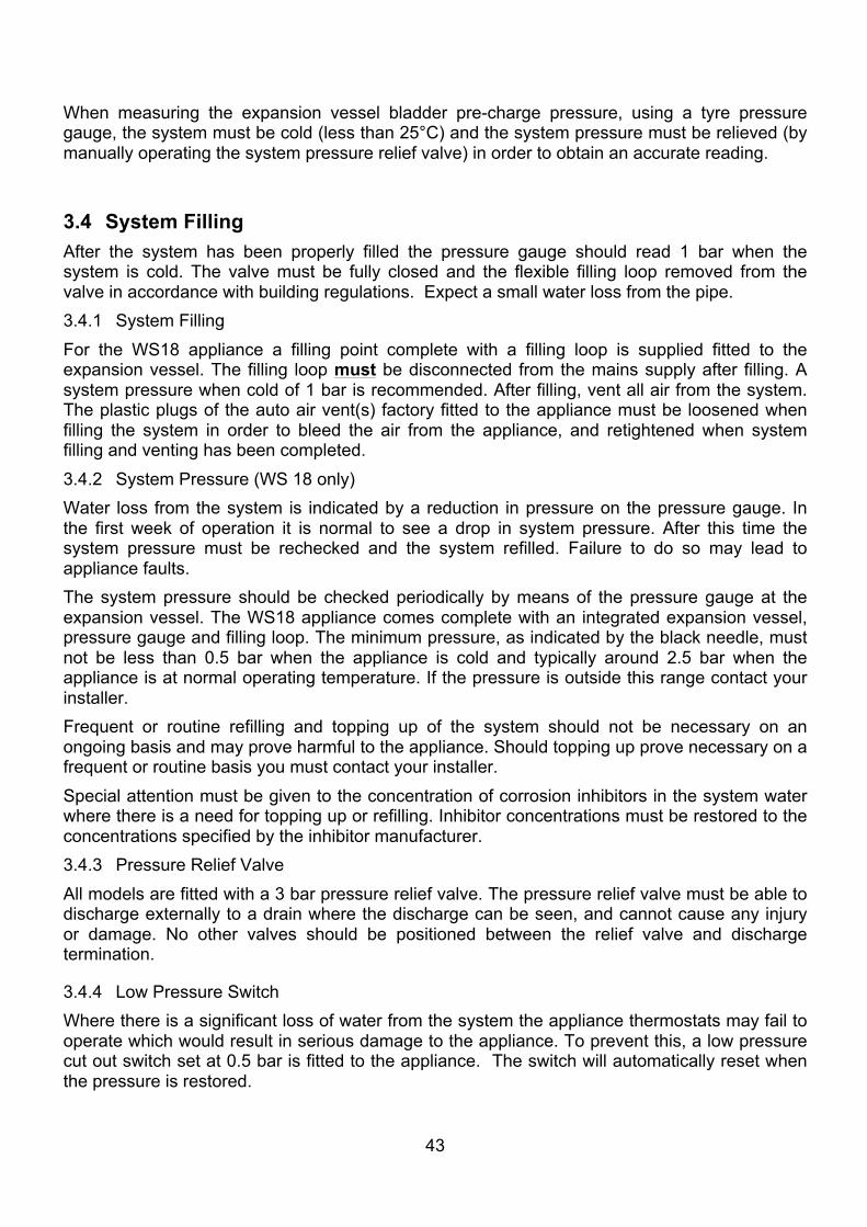
3.4.5 Condensate Trap The Warmflow wood pellet boiler is a non-condensing appliance. However some condensate may be generated at cold start up. For this reason a condensate trap is fitted to collect any condensate which may form, see Figure 60. The condensate trap is fitted with a length of flexible plastic drainage hose. The drainage hose should be connected to an internal soil stack or waste pipe, an external gully hopper or soakaway. It is recommended that the drainage pipe should have a minimum fall of 1:20. The drainage hose must not be affected by any blockage which could lead to condensation backfilling into the heat exchanger of the appliance causing corrosion.
Figure 60: Condensate Trap Plumbing.
Condensate drain pipe from boiler
Condensate trap (supplied)
Condensate outlet to drain
45
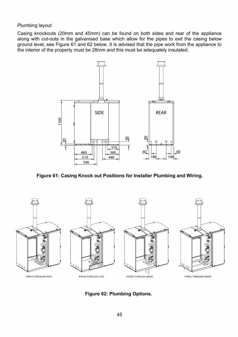
Plumbing layout Casing knockouts (20mm and 45mm) can be found on both sides and rear of the appliance along with cut-outs in the galvanised base which allow for the pipes to exit the casing below ground level, see Figure 61 and 62 below. It is advised that the pipe work from the appliance to the interior of the property must be 28mm and this must be adequately insulated.
Figure 61: Casing Knock out Positions for Installer Plumbing and Wiring.
Figure 62: Plumbing Options.
46
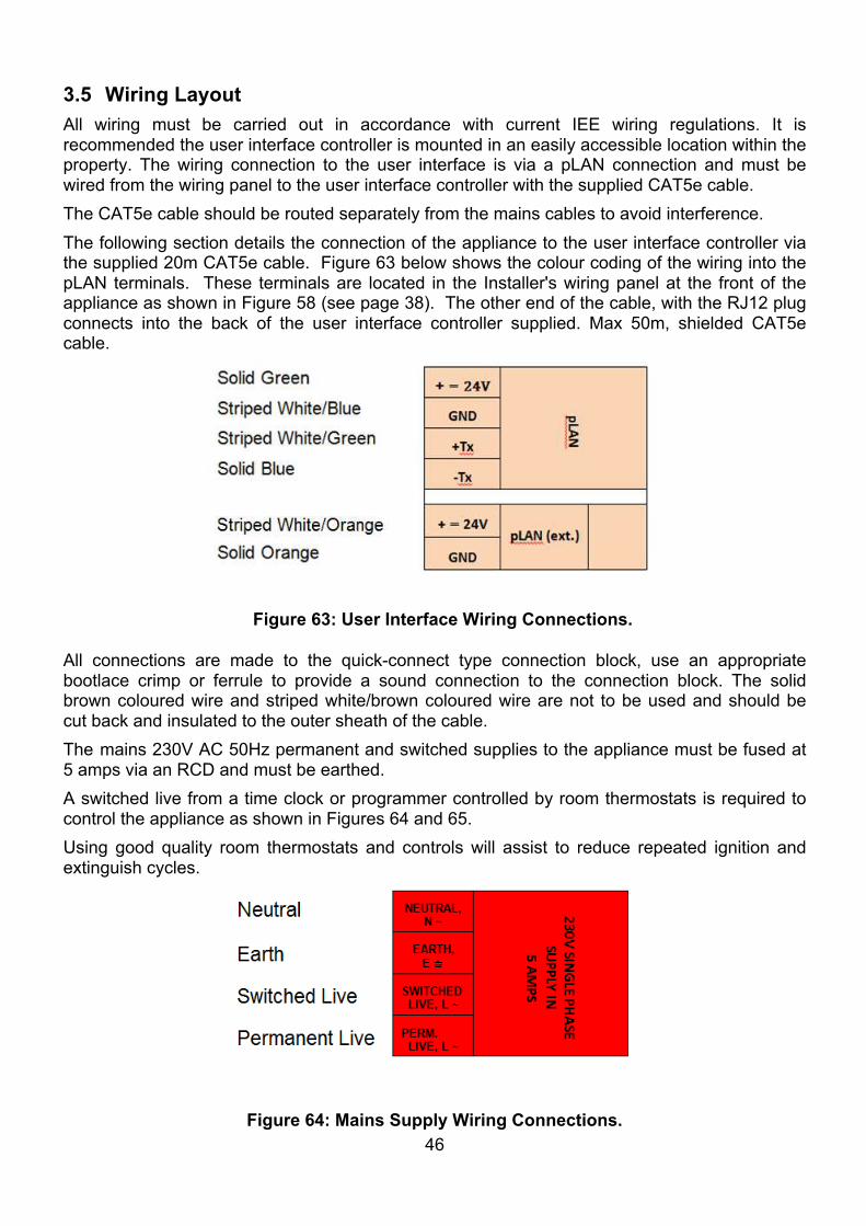
3.5 Wiring Layout All wiring must be carried out in accordance with current IEE wiring regulations. It is recommended the user interface controller is mounted in an easily accessible location within the property. The wiring connection to the user interface is via a pLAN connection and must be wired from the wiring panel to the user interface controller with the supplied CAT5e cable. The CAT5e cable should be routed separately from the mains cables to avoid interference. The following section details the connection of the appliance to the user interface controller via the supplied 20m CAT5e cable. Figure 63 below shows the colour coding of the wiring into the pLAN terminals. These terminals are located in the Installer's wiring panel at the front of the appliance as shown in Figure 58 (see page 38). The other end of the cable, with the RJ12 plug connects into the back of the user interface controller supplied. Max 50m, shielded CAT5e cable.
All connections are made to the quick-connect type connection block, use an appropriate bootlace crimp or ferrule to provide a sound connection to the connection block. The solid brown coloured wire and striped white/brown coloured wire are not to be used and should be cut back and insulated to the outer sheath of the cable. The mains 230V AC 50Hz permanent and switched supplies to the appliance must be fused at 5 amps via an RCD and must be earthed. A switched live from a time clock or programmer controlled by room thermostats is required to control the appliance as shown in Figures 64 and 65. Using good quality room thermostats and controls will assist to reduce repeated ignition and extinguish cycles.
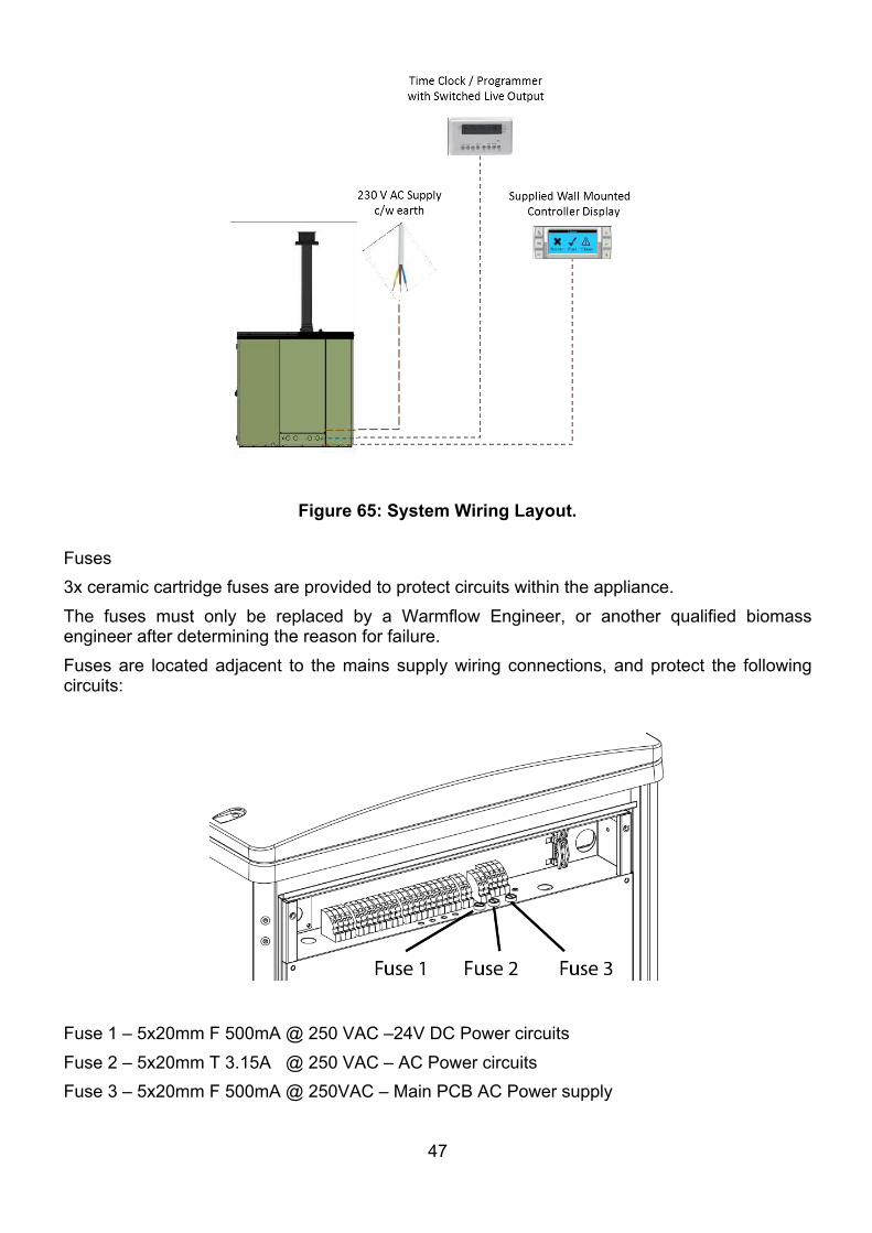
Figure 64: Mains Supply Wiring Connections.
Figure 63: User Interface Wiring Connections.
47
Fuses 3x ceramic cartridge fuses are provided to protect circuits within the appliance. The fuses must only be replaced by a Warmflow Engineer, or another qualified biomass engineer after determining the reason for failure. Fuses are located adjacent to the mains supply wiring connections, and protect the following circuits:
Fuse 1 – 5x20mm F 500mA @ 250 VAC –24V DC Power circuits Fuse 2 – 5x20mm T 3.15A @ 250 VAC – AC Power circuits Fuse 3 – 5x20mm F 500mA @ 250VAC – Main PCB AC Power supply
Figure 65: System Wiring Layout.
48
3.6 Flue System
3.6.1 Flue Outlet Position
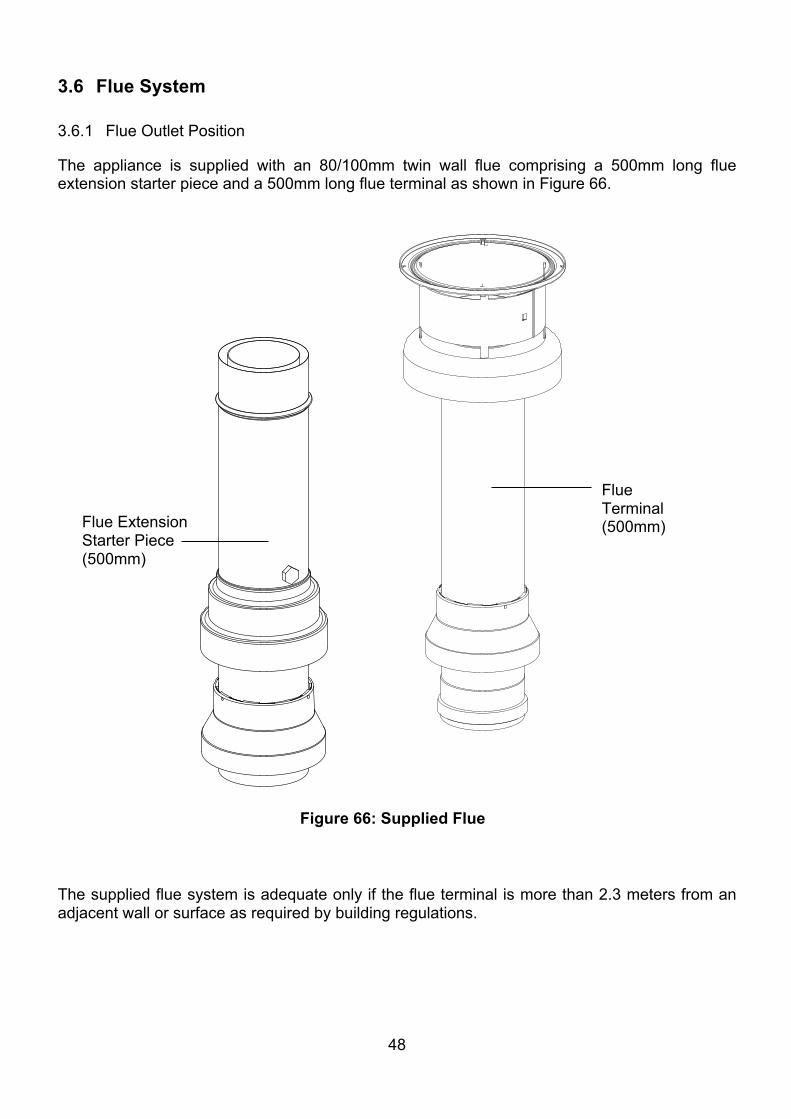
The appliance is supplied with an 80/100mm twin wall flue comprising a 500mm long flue extension starter piece and a 500mm long flue terminal as shown in Figure 66. The supplied flue system is adequate only if the flue terminal is more than 2.3 meters from an adjacent wall or surface as required by building regulations.
Figure 66: Supplied Flue
Flue Extension Starter Piece (500mm)
Flue Terminal (500mm)
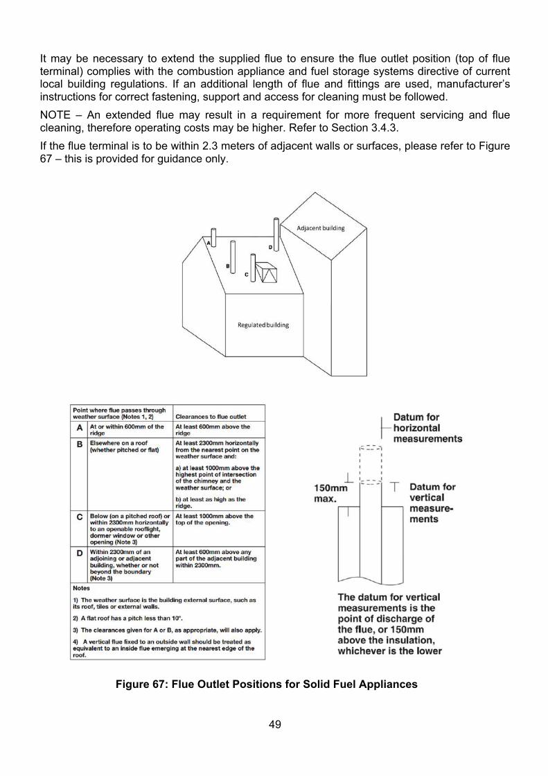
49
It may be necessary to extend the supplied flue to ensure the flue outlet position (top of flue terminal) complies with the combustion appliance and fuel storage systems directive of current local building regulations. If an additional length of flue and fittings are used, manufacturer’s instructions for correct fastening, support and access for cleaning must be followed. NOTE – An extended flue may result in a requirement for more frequent servicing and flue cleaning, therefore operating costs may be higher. Refer to Section 3.4.3. If the flue terminal is to be within 2.3 meters of adjacent walls or surfaces, please refer to Figure 67 – this is provided for guidance only.
Figure 67: Flue Outlet Positions for Solid Fuel Appliances
50
SILICONEGREASE
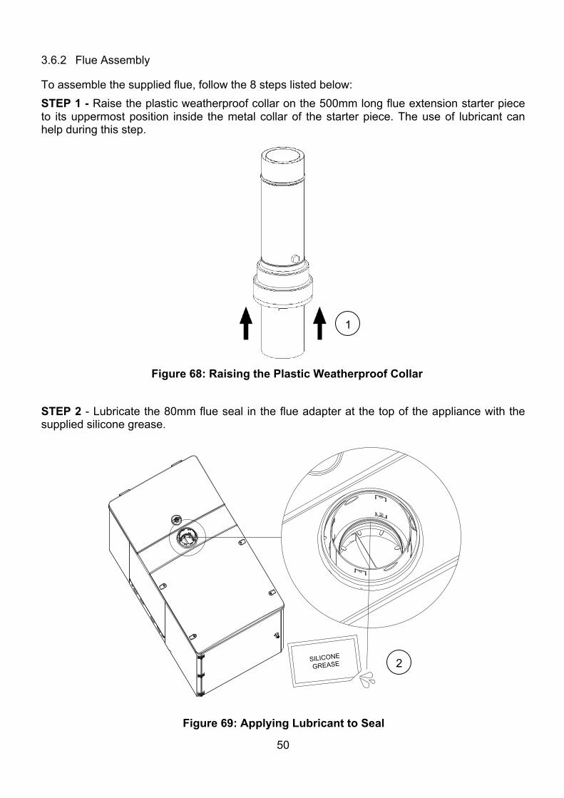
3.6.2 Flue Assembly
To assemble the supplied flue, follow the 8 steps listed below: STEP 1 - Raise the plastic weatherproof collar on the 500mm long flue extension starter piece to its uppermost position inside the metal collar of the starter piece. The use of lubricant can help during this step.
STEP 2 - Lubricate the 80mm flue seal in the flue adapter at the top of the appliance with the supplied silicone grease.
1
Figure 68: Raising the Plastic Weatherproof Collar
Figure 69: Applying Lubricant to Seal
2
51
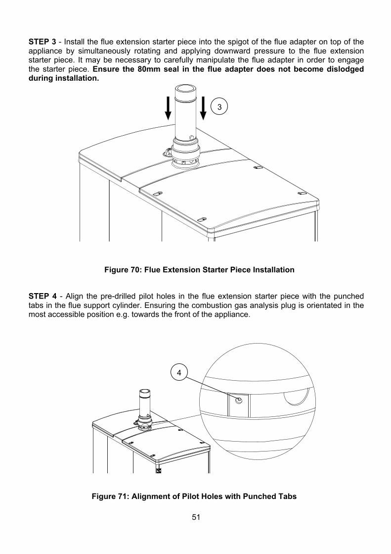
STEP 3 - Install the flue extension starter piece into the spigot of the flue adapter on top of the appliance by simultaneously rotating and applying downward pressure to the flue extension starter piece. It may be necessary to carefully manipulate the flue adapter in order to engage the starter piece. Ensure the 80mm seal in the flue adapter does not become dislodged during installation.
STEP 4 - Align the pre-drilled pilot holes in the flue extension starter piece with the punched tabs in the flue support cylinder. Ensuring the combustion gas analysis plug is orientated in the most accessible position e.g. towards the front of the appliance.
3
4
Figure 70: Flue Extension Starter Piece Installation
Figure 71: Alignment of Pilot Holes with Punched Tabs
52
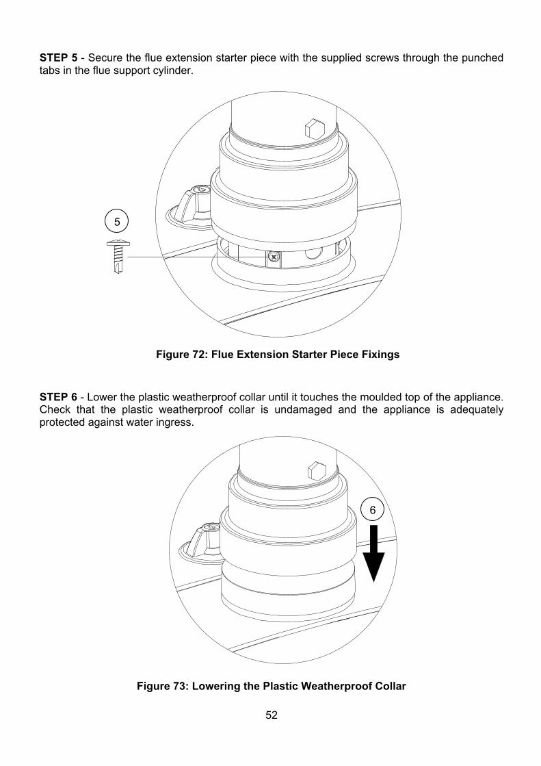
STEP 5 - Secure the flue extension starter piece with the supplied screws through the punched tabs in the flue support cylinder. STEP 6 - Lower the plastic weatherproof collar until it touches the moulded top of the appliance. Check that the plastic weatherproof collar is undamaged and the appliance is adequately protected against water ingress.
5
6
Figure 72: Flue Extension Starter Piece Fixings
Figure 73: Lowering the Plastic Weatherproof Collar
53
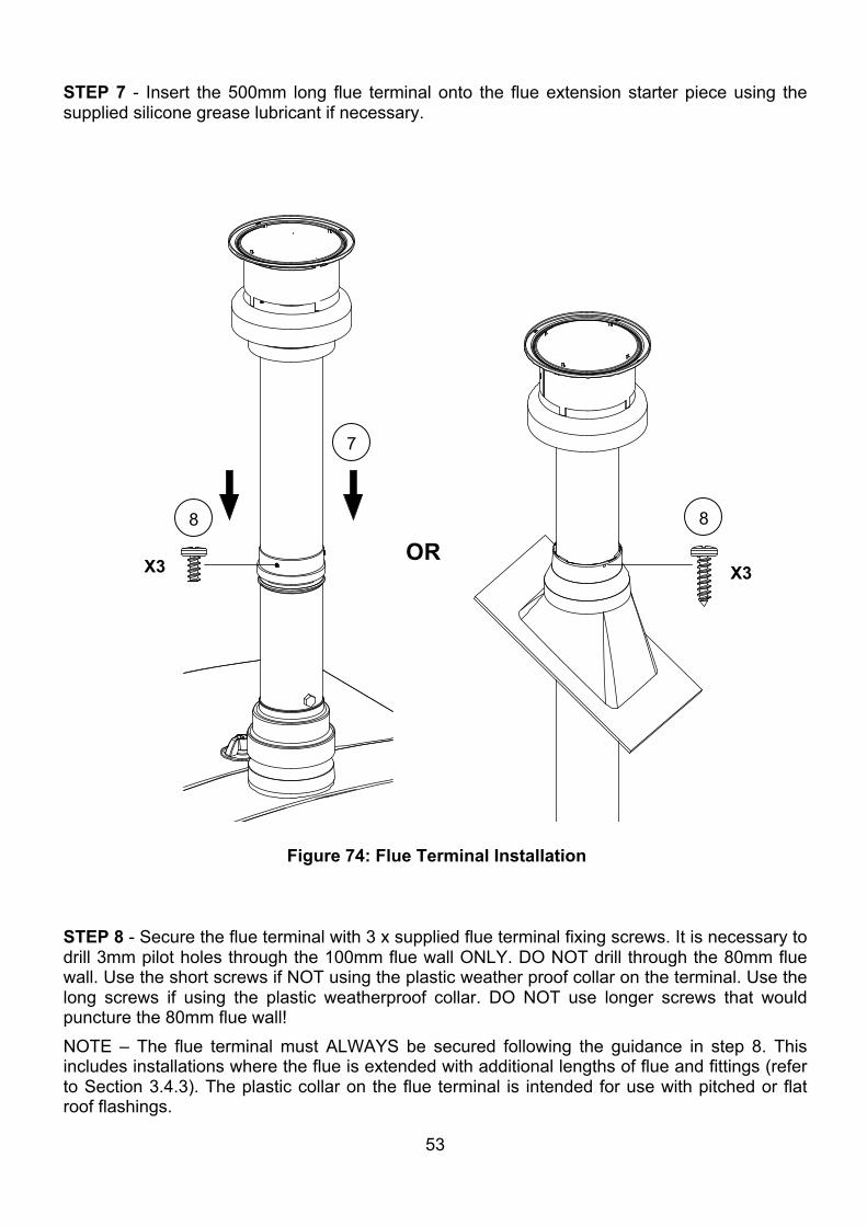
STEP 7 - Insert the 500mm long flue terminal onto the flue extension starter piece using the supplied silicone grease lubricant if necessary. STEP 8 - Secure the flue terminal with 3 x supplied flue terminal fixing screws. It is necessary to drill 3mm pilot holes through the 100mm flue wall ONLY. DO NOT drill through the 80mm flue wall. Use the short screws if NOT using the plastic weather proof collar on the terminal. Use the long screws if using the plastic weatherproof collar. DO NOT use longer screws that would puncture the 80mm flue wall! NOTE – The flue terminal must ALWAYS be secured following the guidance in step 8. This includes installations where the flue is extended with additional lengths of flue and fittings (refer to Section 3.4.3). The plastic collar on the flue terminal is intended for use with pitched or flat roof flashings.
X3 X3
7
8 8
Figure 74: Flue Terminal Installation
OR
54
3.6.3 Extended Flue Assembly
The flue supplied with the appliance (shown in Figure 66) can be extended if necessary to ensure the flue outlet position complies with the requirements set out in Figure 67. IMPORTANT – Extending the supplied flue will increase resistance and demand on the exhaust fan of the appliance. As a result, it will be necessary to service the appliance and clean the flue more frequently if the flue is extended (Refer to Sections 4.2 and 4.3). Extended flues are also more difficult and time consuming to clean correctly. The level of difficulty and time involved increases as the flue length and number of bends in the extended flue increases. More frequent and time consuming servicing and cleaning activities associated with extended flues results in higher operating costs for the appliance when compared to an installation where the standard short flue is installed. (Refer to Figure 67). Extending the flue should be avoided where possible, however flue outlet position and compliance with the combustion appliance and fuel storage systems directive of current local building regulations is of primary importance. Flue extensions can be avoided by careful consideration of where the appliance is sited in relation to nearby buildings prior to installation. If a flue extension is unavoidable, every effort should be made to keep the complete flue construction as short as possible and as straight as possible i.e. without bends to reduce resistance through the flue system and with due consideration given to access for cleaning.
The following rules MUST be observed when installing an extended flue:
• The flue installation must be completed by a Warmflow engineer or qualified biomass engineer
• The flue installation must comply with the requirements set out in Figure 67. • Keep the extended flue as short as possible • Keep the extended flue as straight and vertical as possible i.e. avoid using bends and
long diagonal sections. • If the use of bends is unavoidable, always use them in pairs so that the inlet to the
lowermost bend is vertical and the outlet from the uppermost bend is vertical. • Never use more than four 45⁰ bends in a complete extended flue system. • Ensure the extended flue does not exceed the maximum allowable equivalent length of
6.0 metres. NOTE – 1 x 45⁰ bend has an equivalent length of 0.5m.
Example Calculations: Example 1: No bends fitted Example 2: 2 x 45⁰ bends fitted Length of straight flue 6.0m Length of straight flue 6.0m
No bends 0.0m 2 x 45⁰ Bends 1.0m
Equivalent length 6.0m Equivalent length 7.0m Equivalent length within the max. allowable Equivalent length over max. allowable INSTALLATION ACCEPTABLE. INSTALLATION NOT ACCEPTABLE.
55
• Ensure flue components are positioned so they do not obstruct the opening/closing of doors or removal/re-fitting of panels on the appliance.
• Ensure a seal is present, intact and correctly placed at ALL flue joints. The use of lubricant can help seals to remain in their recess during installation – NEVER assemble a flue component without the manufacturers seal in place.
• Flue pipes must be installed with a minimum slope of 45⁰ from horizontal in order to minimise resistance in the flue system.
• Never deviate more than 45⁰ in a single bend e.g. by connecting two 45⁰ bends. • Keep female ends of flue components down and male ends up to avoid water ingress. • Avoid shortening the flue extension starter piece except to connect a straight extension
piece. Connection of a 45⁰ bend to a shortened flue extension starter piece is NOT permitted.
• Make clean square cuts to flue extension parts if they need to be reduced in length, taking care not to cause damage by the clamping and cutting methods used.
• Always remove swarf form cut flue sections to avoid build-up of ash etc during operation of the appliance.
• Never attempt to fabricate bespoke flue components e.g. bends at irregular angles from extension pieces by cutting, bending, welding or any other process
• Never modify the flue terminal • Always install the flue terminal in the vertical orientation. • Never drill or use screws, rivets or any other fixing that would pierce the 80mm diameter
parts of any flue component and thus permit leakage of flue gases • Ensure there are no blockages or defects on flue components prior to installation • Use appropriate bracketry (See Figure 81) to adequately secure all sections of an
extended flue with a maximum support spacing of 1.5m between brackets. • The uppermost flue support bracket on an extended flue must be positioned within 1m
from the top of the flue terminal. • Always secure the flue terminal using the fixing screws provided (Refer to Figure 74) • Once assembled, the extended flue must be checked for airtightness and security
Warning
• Isolate the mains electricity supply to the appliance before installation • Do not stand on top of the appliance during installation. The load bearing capacity of the
top surfaces is not adequate.
56
4 COMMISSIONING, SERVICING AND FLUE CLEANING 4.1 Commissioning – Approximate time to complete: 2 hours Note: It is the responsibility of the installer to ensure that the appliance is properly commissioned by a Warmflow Engineer, or a qualified biomass engineer. Failure to do so WILL invalidate ALL warranties. The commissioning process consists of 8 main steps – familiarise yourself with all of the steps before proceeding:
1. Ensuring the boiler is undamaged and correctly installed on site 2. Mechanical and heating system checks 3. Electrical checks 4. Assignment of required parameters 5. Initial firing of the appliance 6. Fuel regulation check 7. Flue gas analysis 8. User introduction to the appliance
STEP 1 – Ensuring the boiler is undamaged and correctly installed on site. Ensure the installation requirements listed in Section 3 of this manual have been met, and complete any remedial actions before proceeding with the commissioning procedures. Visually inspect the appliance to ensure no damage has been caused during transportation or installation, reporting this before proceeding. The IP (Ingress Protection) rating of the product should be maintained by the use of correct cable glands and pipework grommets for installed items. Ensure no foreign objects are obstructing the flue or combustion chamber, and the area is safe for persons in the area before proceeding.
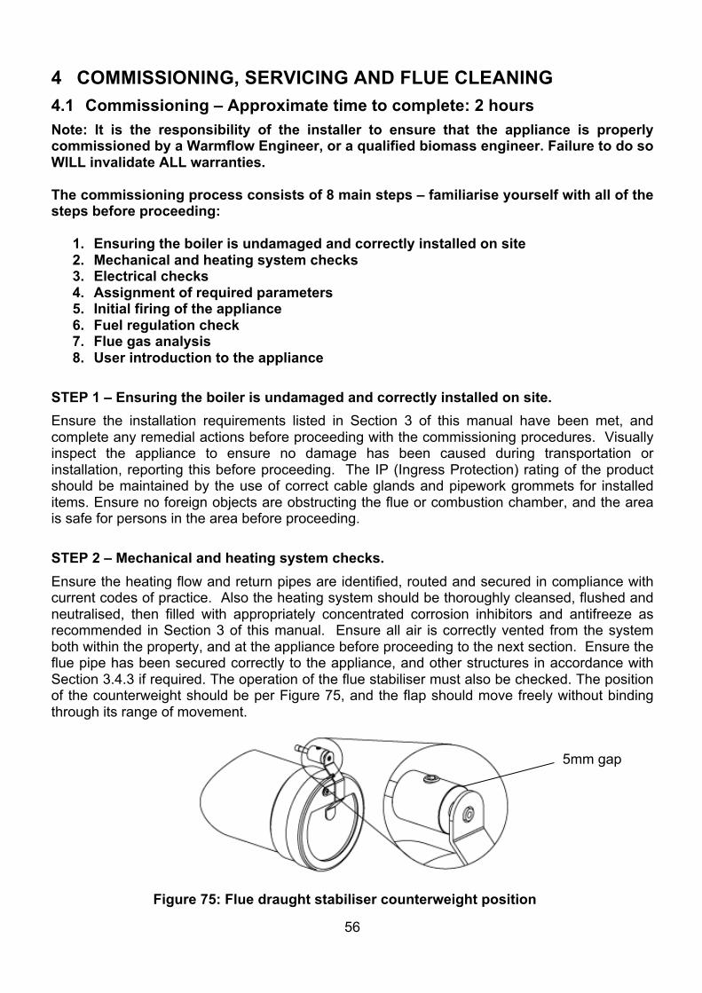
STEP 2 – Mechanical and heating system checks. Ensure the heating flow and return pipes are identified, routed and secured in compliance with current codes of practice. Also the heating system should be thoroughly cleansed, flushed and neutralised, then filled with appropriately concentrated corrosion inhibitors and antifreeze as recommended in Section 3 of this manual. Ensure all air is correctly vented from the system both within the property, and at the appliance before proceeding to the next section. Ensure the flue pipe has been secured correctly to the appliance, and other structures in accordance with Section 3.4.3 if required. The operation of the flue stabiliser must also be checked. The position of the counterweight should be per Figure 75, and the flap should move freely without binding through its range of movement.
5mm gap
Figure 75: Flue draught stabiliser counterweight position
57
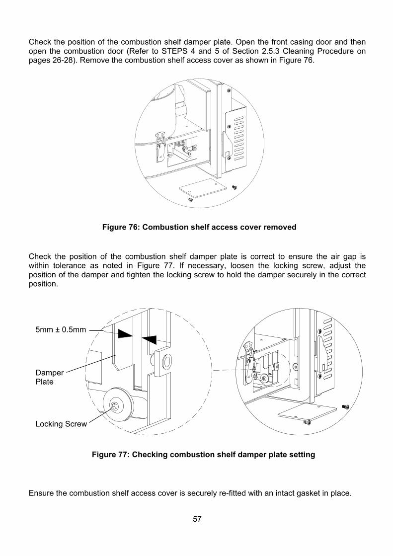
Check the position of the combustion shelf damper plate. Open the front casing door and then open the combustion door (Refer to STEPS 4 and 5 of Section 2.5.3 Cleaning Procedure on pages 26-28). Remove the combustion shelf access cover as shown in Figure 76.
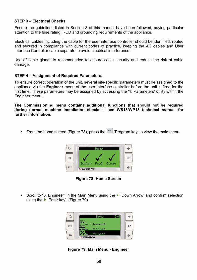
Check the position of the combustion shelf damper plate is correct to ensure the air gap is within tolerance as noted in Figure 77. If necessary, loosen the locking screw, adjust the position of the damper and tighten the locking screw to hold the damper securely in the correct position.
Ensure the combustion shelf access cover is securely re-fitted with an intact gasket in place.
Figure 76: Combustion shelf access cover removed
Locking Screw
5mm ± 0.5mm
Figure 77: Checking combustion shelf damper plate setting
Damper Plate
58
STEP 3 – Electrical Checks Ensure the guidelines listed in Section 3 of this manual have been followed, paying particular attention to the fuse rating, RCD and grounding requirements of the appliance. Electrical cables including the cable for the user interface controller should be identified, routed and secured in compliance with current codes of practice, keeping the AC cables and User Interface Controller cable separate to avoid electrical interference. Use of cable glands is recommended to ensure cable security and reduce the risk of cable damage. STEP 4 – Assignment of Required Parameters. To ensure correct operation of the unit, several site-specific parameters must be assigned to the appliance via the Engineer menu of the user interface controller before the unit is fired for the first time. These parameters may be assigned by accessing the ‘1. Parameters’ utility within the Engineer menu.
The Commissioning menu contains additional functions that should not be required during normal machine installation checks – see WS18/WP18 technical manual for further information.
• From the home screen (Figure 78), press the ‘Program key’ to view the main menu.
• Scroll to “5. Engineer” in the Main Menu using the ‘Down Arrow’ and confirm selection using the ‘Enter key’. (Figure 79)
Figure 78: Home Screen
Figure 79: Main Menu - Engineer
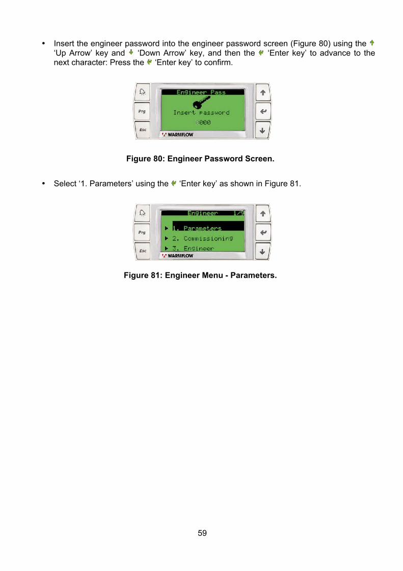
59
• Insert the engineer password into the engineer password screen (Figure 80) using the ‘Up Arrow’ key and ‘Down Arrow’ key, and then the ‘Enter key’ to advance to the next character: Press the ‘Enter key’ to confirm.
• Select ‘1. Parameters’ using the ‘Enter key’ as shown in Figure 81.
Figure 80: Engineer Password Screen.
Figure 81: Engineer Menu - Parameters.
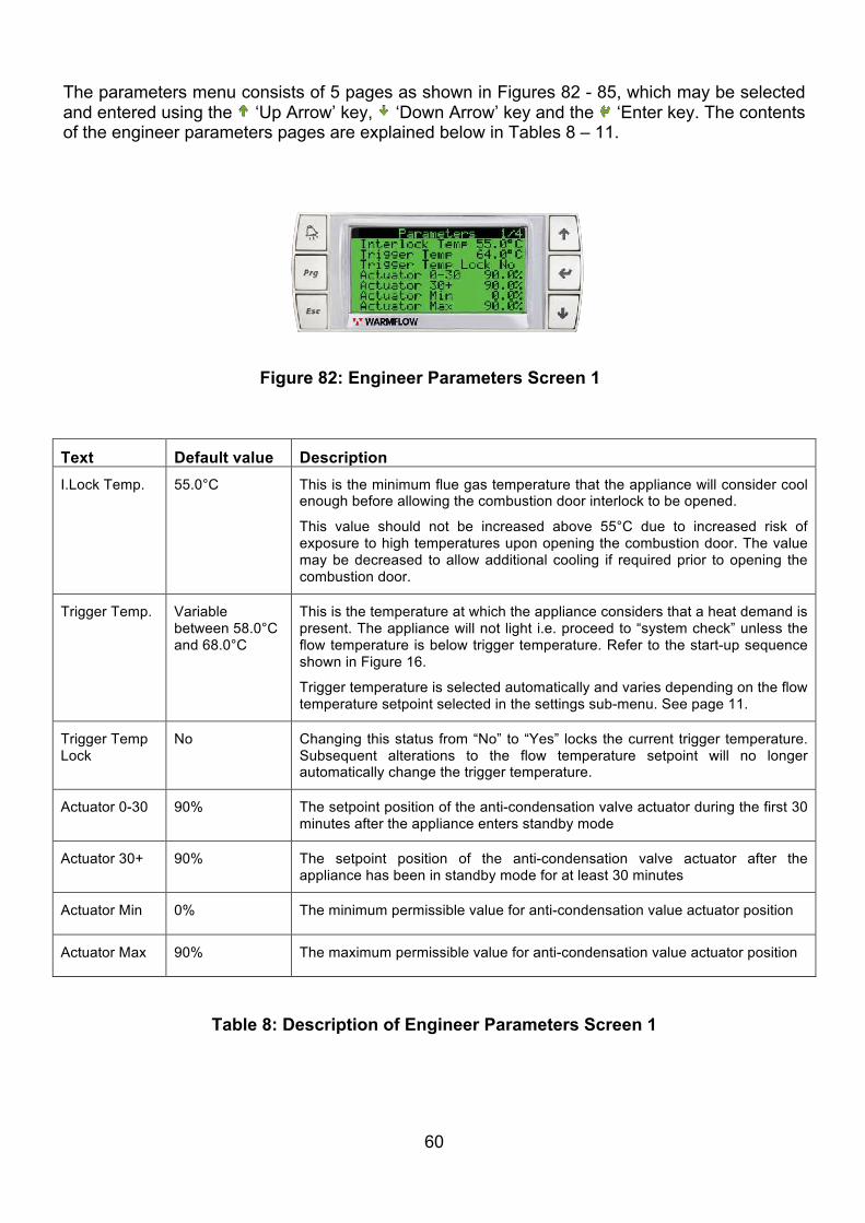
60
The parameters menu consists of 5 pages as shown in Figures 82 - 85, which may be selected and entered using the ‘Up Arrow’ key, ‘Down Arrow’ key and the ‘Enter key. The contents of the engineer parameters pages are explained below in Tables 8 – 11.
Text Default value Description I.Lock Temp. 55.0°C This is the minimum flue gas temperature that the appliance will consider cool
enough before allowing the combustion door interlock to be opened.
This value should not be increased above 55°C due to increased risk of exposure to high temperatures upon opening the combustion door. The value may be decreased to allow additional cooling if required prior to opening the combustion door.
Trigger Temp. Variable between 58.0°C and 68.0°C
This is the temperature at which the appliance considers that a heat demand is present. The appliance will not light i.e. proceed to “system check” unless the flow temperature is below trigger temperature. Refer to the start-up sequence shown in Figure 16.
Trigger temperature is selected automatically and varies depending on the flow temperature setpoint selected in the settings sub-menu. See page 11.
Trigger Temp Lock
No Changing this status from “No” to “Yes” locks the current trigger temperature. Subsequent alterations to the flow temperature setpoint will no longer automatically change the trigger temperature.
Actuator 0-30 90% The setpoint position of the anti-condensation valve actuator during the first 30 minutes after the appliance enters standby mode
Actuator 30+ 90% The setpoint position of the anti-condensation valve actuator after the appliance has been in standby mode for at least 30 minutes
Actuator Min 0% The minimum permissible value for anti-condensation value actuator position
Actuator Max 90% The maximum permissible value for anti-condensation value actuator position
Table 8: Description of Engineer Parameters Screen 1
Figure 82: Engineer Parameters Screen 1
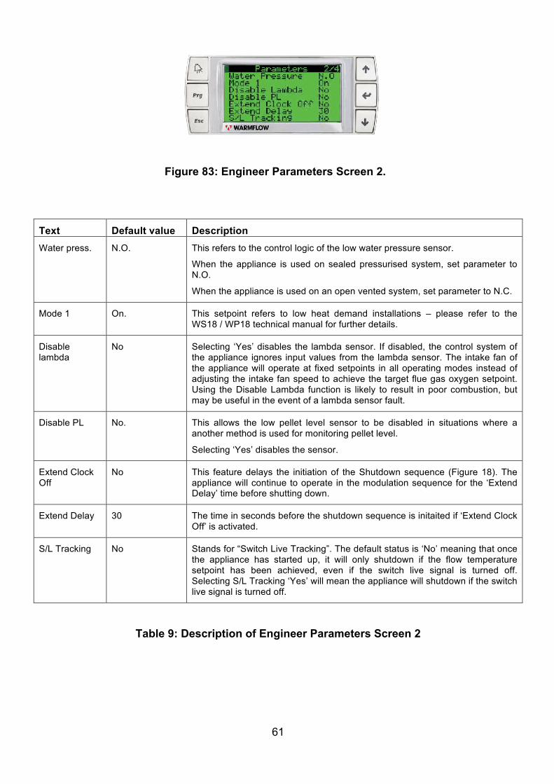
61
Text Default value Description Water press. N.O. This refers to the control logic of the low water pressure sensor.
When the appliance is used on sealed pressurised system, set parameter to N.O.
When the appliance is used on an open vented system, set parameter to N.C.
Mode 1 On. This setpoint refers to low heat demand installations – please refer to the WS18 / WP18 technical manual for further details.
Disable lambda
No Selecting ‘Yes’ disables the lambda sensor. If disabled, the control system of the appliance ignores input values from the lambda sensor. The intake fan of the appliance will operate at fixed setpoints in all operating modes instead of adjusting the intake fan speed to achieve the target flue gas oxygen setpoint. Using the Disable Lambda function is likely to result in poor combustion, but may be useful in the event of a lambda sensor fault.
Disable PL No. This allows the low pellet level sensor to be disabled in situations where a another method is used for monitoring pellet level.
Selecting ‘Yes’ disables the sensor.
Extend Clock Off
No This feature delays the initiation of the Shutdown sequence (Figure 18). The appliance will continue to operate in the modulation sequence for the ‘Extend Delay’ time before shutting down.
Extend Delay 30 The time in seconds before the shutdown sequence is initaited if ‘Extend Clock Off’ is activated.
S/L Tracking No Stands for “Switch Live Tracking”. The default status is ‘No’ meaning that once the appliance has started up, it will only shutdown if the flow temperature setpoint has been achieved, even if the switch live signal is turned off. Selecting S/L Tracking ‘Yes’ will mean the appliance will shutdown if the switch live signal is turned off.
Table 9: Description of Engineer Parameters Screen 2
Figure 83: Engineer Parameters Screen 2.
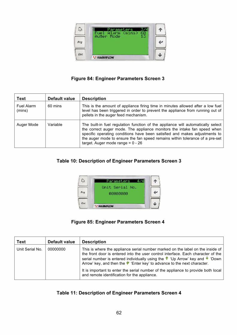
62
Text Default value Description Fuel Alarm (mins)
60 mins This is the amount of appliance firing time in minutes allowed after a low fuel level has been triggered in order to prevent the appliance from running out of pellets in the auger feed mechanism.
Auger Mode Variable The built-in fuel regulation function of the appliance will automatically select the correct auger mode. The appliance monitors the intake fan speed when specific operating conditions have been satisfied and makes adjustments to the auger mode to ensure the fan speed remains within tolerance of a pre-set target. Auger mode range = 0 - 26
Table 10: Description of Engineer Parameters Screen 3
Text Default value Description Unit Serial No. 00000000 This is where the appliance serial number marked on the label on the inside of
the front door is entered into the user control interface. Each character of the serial number is entered individually using the ‘Up Arrow’ key and ‘Down Arrow’ key, and then the ‘Enter key’ to advance to the next character.
It is important to enter the serial number of the appliance to provide both local and remote identification for the appliance.
Table 11: Description of Engineer Parameters Screen 4
Figure 84: Engineer Parameters Screen 3
Figure 85: Engineer Parameters Screen 4
63
STEP 5 – Initial Firing of the Appliance Before firing, ensure that the combustion pot and ash pan are in place as they may have been displaced during transport/installation (refer to Figure 2). Switch the appliance on, ensuring all controls are calling for heat. Under normal conditions the appliance will proceed through the start-up sequence as shown in Figure 16 on page 15. The appliance will use its temperature sensors to determine the required heating demand for the property and, if conditions are met, proceed to the modulation sequence shown in Figure 17. During this time, observe the ‘Information’ menu in order to monitor time clock status, temperatures, operating modes, draught and intake fan information. Guidance on typical values is provided in Tables 2 and 3 of this document. The combustion settings are factory set and cannot be altered, the exhaust fan works under negative pressure (draws exhausted air out of the combustion chamber) and is controlled by the differential pressure sensor. The intake fan is controlled by the lambda sensor fitted to the appliance. Intake fan speed will modulate depending on the auger feed rate. STEP 6 – Fuel regulation check The fuel regulation feature regulates the fuel feed via the auger mechanism into the combustion chamber of the appliance. Fuel regulation occurs in powerband 5 only, therefore the appliance should be kept operational until powerband 5 is reached. The main function of the fuel regulation feature is to automatically select the correct auger mode to achieve the target intake fan speed of 7700rpm in Powerband 5. The following 3 scenarios can occur during operation:
1. The appliance is operating in Powerband 5 and the intake fan speed is 7700 ± 300rpm. Fuel regulation will not activate and the auger mode will not change.
2. The appliance is operating in Powerband 5 and the intake fan speed is ≤ 7400rpm. Fuel regulation will activate and increase the auger mode accordingly.
3. The appliance is operating in Powerband 5 and the intake fan speed is ≥ 8000rpm. Fuel regulation will activate and decrease the auger mode accordingly.
The appliance needs to operate in Powerband 5 and the flue gas oxygen content needs to remain stable within permissible limits for a period of 13 minutes before any change in auger mode will take place. Navigate to the information screens to observe the intake fan speed of the appliance when firing in Powerband 5. Refer to Figure 13 and 14. If the intake fan speed is low or high then the auger mode should adjust as noted in points 2 and 3 above. The change in auger mode can be observed in Parameters screen 3 (Refer to Figure 84). A fuel regulation sequence is part of factory testing, therefore the auger mode of the appliance at initial firing should be correct to achieve the required intake fan speed of 7700rpm. If not, always allow sufficient time for the fuel regulation feature to activate. NOTE – Fuel regulation will not activate if:
• There is an active pellet level low alert – Ensure the fuel hopper is sufficiently full • The lambda sensor has been disabled – Refer to Figure 83 and Table 9
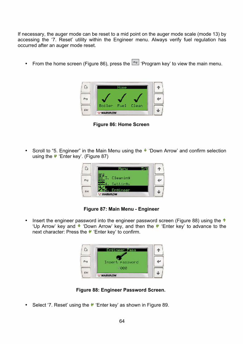
64
If necessary, the auger mode can be reset to a mid point on the auger mode scale (mode 13) by accessing the ‘7. Reset’ utility within the Engineer menu. Always verify fuel regulation has occurred after an auger mode reset.
• From the home screen (Figure 86), press the ‘Program key’ to view the main menu.
• Scroll to “5. Engineer” in the Main Menu using the ‘Down Arrow’ and confirm selection using the ‘Enter key’. (Figure 87)
• Insert the engineer password into the engineer password screen (Figure 88) using the ‘Up Arrow’ key and ‘Down Arrow’ key, and then the ‘Enter key’ to advance to the next character: Press the ‘Enter key’ to confirm.
• Select ‘7. Reset’ using the ‘Enter key’ as shown in Figure 89.
Figure 86: Home Screen
Figure 87: Main Menu - Engineer
Figure 88: Engineer Password Screen.
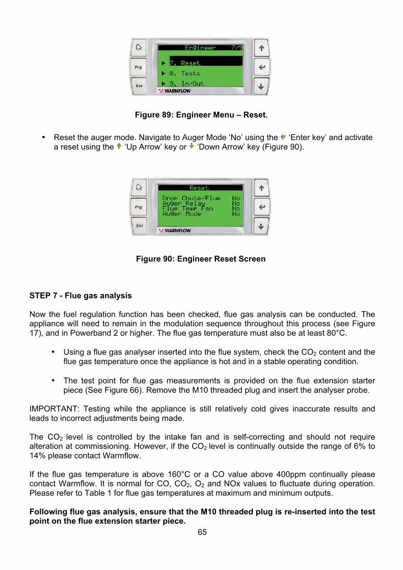
65
• Reset the auger mode. Navigate to Auger Mode ‘No’ using the ‘Enter key’ and activate a reset using the ‘Up Arrow’ key or ‘Down Arrow’ key (Figure 90).
STEP 7 - Flue gas analysis
Now the fuel regulation function has been checked, flue gas analysis can be conducted. The appliance will need to remain in the modulation sequence throughout this process (see Figure 17), and in Powerband 2 or higher. The flue gas temperature must also be at least 80°C.
• Using a flue gas analyser inserted into the flue system, check the CO2 content and the
flue gas temperature once the appliance is hot and in a stable operating condition.
• The test point for flue gas measurements is provided on the flue extension starter piece (See Figure 66). Remove the M10 threaded plug and insert the analyser probe.
IMPORTANT: Testing while the appliance is still relatively cold gives inaccurate results and leads to incorrect adjustments being made. The CO2
level is controlled by the intake fan and is self-correcting and should not require alteration at commissioning. However, if the CO2
level is continually outside the range of 6% to 14% please contact Warmflow. If the flue gas temperature is above 160°C or a CO value above 400ppm continually please contact Warmflow. It is normal for CO, CO2, O2 and NOx values to fluctuate during operation. Please refer to Table 1 for flue gas temperatures at maximum and minimum outputs. Following flue gas analysis, ensure that the M10 threaded plug is re-inserted into the test point on the flue extension starter piece.
Figure 90: Engineer Reset Screen
Figure 89: Engineer Menu – Reset.
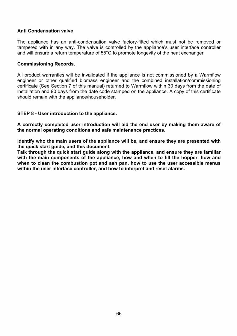
66
Anti Condensation valve The appliance has an anti-condensation valve factory-fitted which must not be removed or tampered with in any way. The valve is controlled by the appliance’s user interface controller and will ensure a return temperature of 55°C to promote longevity of the heat exchanger. Commissioning Records. All product warranties will be invalidated if the appliance is not commissioned by a Warmflow engineer or other qualified biomass engineer and the combined installation/commissioning certificate (See Section 7 of this manual) returned to Warmflow within 30 days from the date of installation and 90 days from the date code stamped on the appliance. A copy of this certificate should remain with the appliance/householder. STEP 8 - User introduction to the appliance. A correctly completed user introduction will aid the end user by making them aware of the normal operating conditions and safe maintenance practices. Identify who the main users of the appliance will be, and ensure they are presented with the quick start guide, and this document. Talk through the quick start guide along with the appliance, and ensure they are familiar with the main components of the appliance, how and when to fill the hopper, how and when to clean the combustion pot and ash pan, how to use the user accessible menus within the user interface controller, and how to interpret and reset alarms.
67
4.2 Servicing To ensure continued reliable operation, fuel economy and to maintain warranty, the appliance must be serviced when indicated by the user control interface. Servicing must be conducted by a Warmflow engineer or other qualified biomass engineer in accordance with Section 4.2 of this manual. Engineers should refer to the Servicing section of the WS18/WP18 Technical Manual for the full servicing procedure. A service history must be maintained in Section 8 of this manual. NOTE – It is advisable to service the appliance immediately prior to the start of the heating season.
4.3 Flue Cleaning It is extremely important, especially in the case of extended flues, to have all internal surfaces of the complete flue system cleaned during servicing of the appliance and as prescribed by local legislation. Failure to clean the flue as described in the WS18/WP18 technical manual can increase the risk of fly ash, creosote and other by-products of biomass combustion accumulating in the flue, with the potential to cause a flue fire. Flue cleaning should only be conducted by a qualified chimney sweep or by a Warmflow engineer or other qualified biomass engineer. Approved personnel should refer to the Servicing section of the WS18/WP18 Technical Manual for the full flue cleaning procedure.
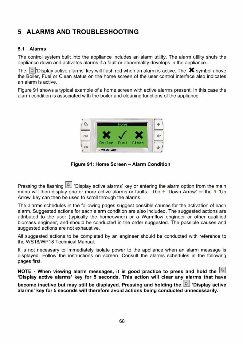
68
5 ALARMS AND TROUBLESHOOTING 5.1 Alarms The control system built into the appliance includes an alarm utility. The alarm utility shuts the appliance down and activates alarms if a fault or abnormality develops in the appliance. The ‘Display active alarms’ key will flash red when an alarm is active. The symbol above the Boiler, Fuel or Clean status on the home screen of the user control interface also indicates an alarm is active. Figure 91 shows a typical example of a home screen with active alarms present. In this case the alarm condition is associated with the boiler and cleaning functions of the appliance.
Pressing the flashing ‘Display active alarms’ key or entering the alarm option from the main menu will then display one or more active alarms or faults. The ‘Down Arrow’ or the ‘Up Arrow’ key can then be used to scroll through the alarms. The alarms schedules in the following pages suggest possible causes for the activation of each alarm. Suggested actions for each alarm condition are also included. The suggested actions are attributed to the user (typically the homeowner) or a Warmflow engineer or other qualified biomass engineer, and should be conducted in the order suggested. The possible causes and suggested actions are not exhaustive. All suggested actions to be completed by an engineer should be conducted with reference to the WS18/WP18 Technical Manual. It is not necessary to immediately isolate power to the appliance when an alarm message is displayed. Follow the instructions on screen. Consult the alarms schedules in the following pages first.
NOTE - When viewing alarm messages, it is good practice to press and hold the ‘Display active alarms’ key for 5 seconds. This action will clear any alarms that have become inactive but may still be displayed. Pressing and holding the ‘Display active alarms’ key for 5 seconds will therefore avoid actions being conducted unnecessarily.
Figure 91: Home Screen – Alarm Condition
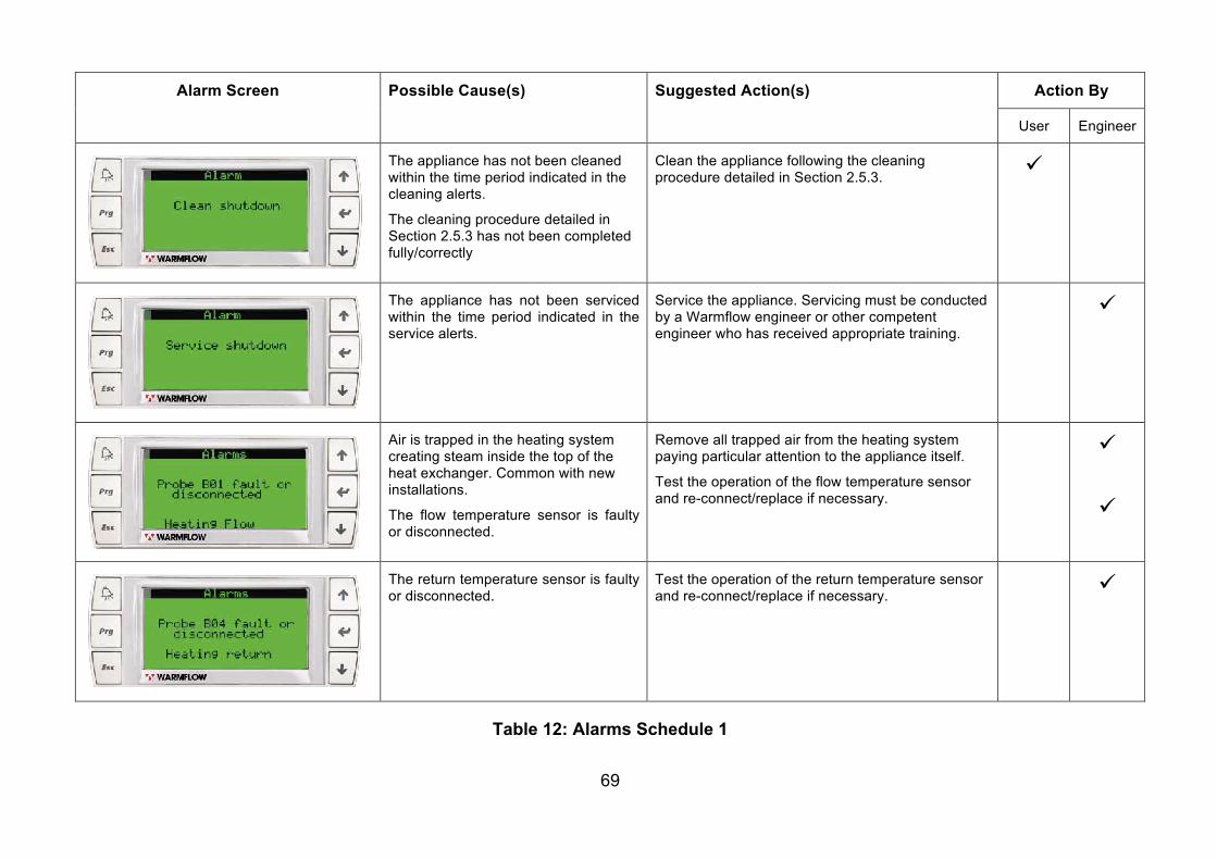
69
Alarm Screen Possible Cause(s) Suggested Action(s) Action By
User Engineer
The appliance has not been cleaned within the time period indicated in the cleaning alerts.
The cleaning procedure detailed in Section 2.5.3 has not been completed fully/correctly
Clean the appliance following the cleaning procedure detailed in Section 2.5.3. ü
The appliance has not been serviced within the time period indicated in the service alerts.
Service the appliance. Servicing must be conducted by a Warmflow engineer or other competent engineer who has received appropriate training.
ü
Air is trapped in the heating system creating steam inside the top of the heat exchanger. Common with new installations.
The flow temperature sensor is faulty or disconnected.
Remove all trapped air from the heating system paying particular attention to the appliance itself.
Test the operation of the flow temperature sensor and re-connect/replace if necessary.
ü
ü
The return temperature sensor is faulty or disconnected.
Test the operation of the return temperature sensor and re-connect/replace if necessary.
ü
Table 12: Alarms Schedule 1
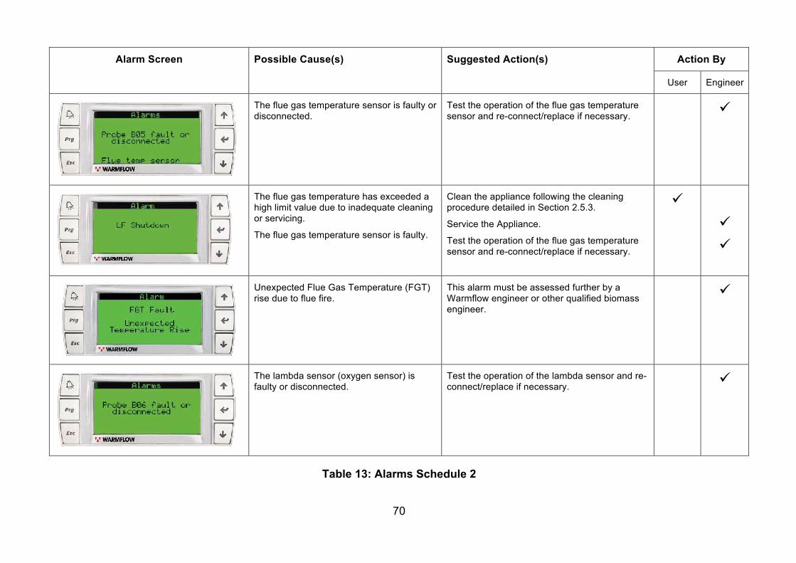
70
Alarm Screen Possible Cause(s) Suggested Action(s) Action By
User Engineer
The flue gas temperature sensor is faulty or disconnected.
Test the operation of the flue gas temperature sensor and re-connect/replace if necessary.
ü
The flue gas temperature has exceeded a high limit value due to inadequate cleaning or servicing.
The flue gas temperature sensor is faulty.
Clean the appliance following the cleaning procedure detailed in Section 2.5.3.
Service the Appliance.
Test the operation of the flue gas temperature sensor and re-connect/replace if necessary.
ü
ü ü
Unexpected Flue Gas Temperature (FGT) rise due to flue fire.
This alarm must be assessed further by a Warmflow engineer or other qualified biomass engineer.
ü
The lambda sensor (oxygen sensor) is faulty or disconnected.
Test the operation of the lambda sensor and re-connect/replace if necessary.
ü
Table 13: Alarms Schedule 2
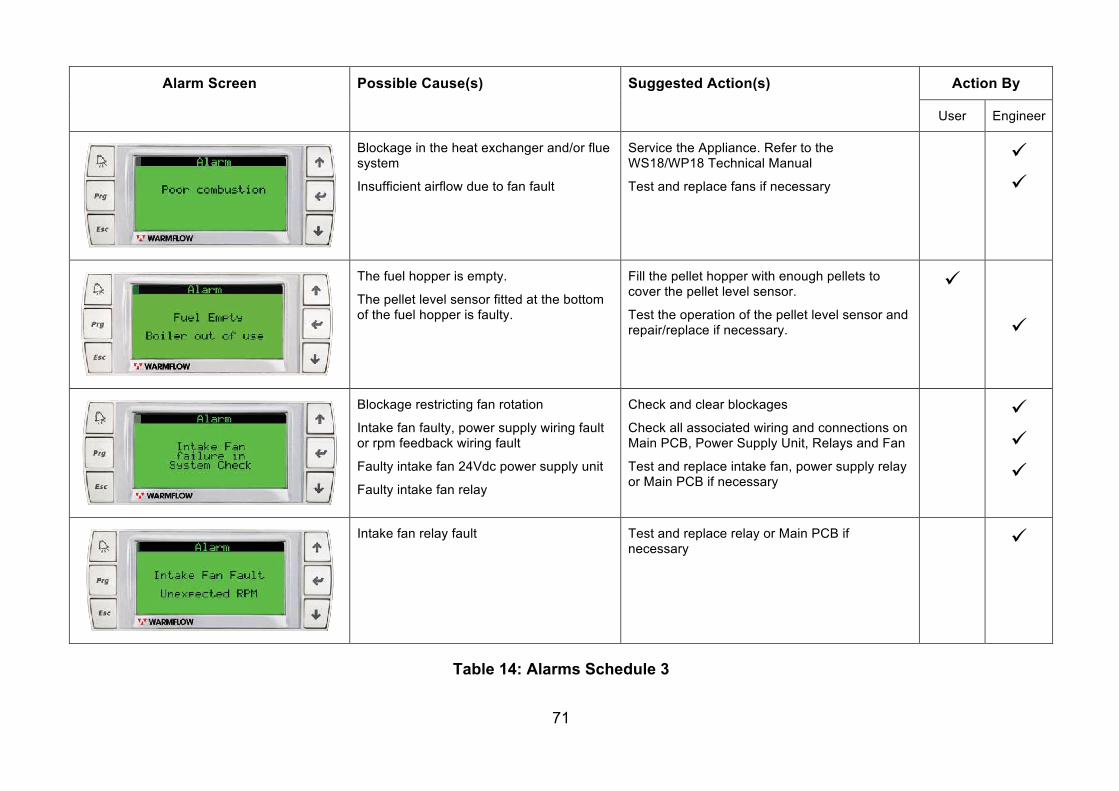
71
Alarm Screen Possible Cause(s) Suggested Action(s) Action By
User Engineer
Blockage in the heat exchanger and/or flue system
Insufficient airflow due to fan fault
Service the Appliance. Refer to the WS18/WP18 Technical Manual
Test and replace fans if necessary
ü ü
The fuel hopper is empty.
The pellet level sensor fitted at the bottom of the fuel hopper is faulty.
Fill the pellet hopper with enough pellets to cover the pellet level sensor.
Test the operation of the pellet level sensor and repair/replace if necessary.
ü
ü
Blockage restricting fan rotation
Intake fan faulty, power supply wiring fault or rpm feedback wiring fault
Faulty intake fan 24Vdc power supply unit
Faulty intake fan relay
Check and clear blockages
Check all associated wiring and connections on Main PCB, Power Supply Unit, Relays and Fan
Test and replace intake fan, power supply relay or Main PCB if necessary
ü ü ü
Intake fan relay fault Test and replace relay or Main PCB if necessary
ü
Table 14: Alarms Schedule 3
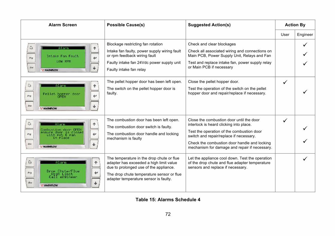
72
Alarm Screen Possible Cause(s) Suggested Action(s) Action By
User Engineer
Blockage restricting fan rotation
Intake fan faulty, power supply wiring fault or rpm feedback wiring fault
Faulty intake fan 24Vdc power supply unit
Faulty intake fan relay
Check and clear blockages
Check all associated wiring and connections on Main PCB, Power Supply Unit, Relays and Fan
Test and replace intake fan, power supply relay or Main PCB if necessary
ü ü ü
The pellet hopper door has been left open.
The switch on the pellet hopper door is faulty.
Close the pellet hopper door.
Test the operation of the switch on the pellet hopper door and repair/replace if necessary.
ü ü
The combustion door has been left open.
The combustion door switch is faulty.
The combustion door handle and locking mechanism is faulty
Close the combustion door until the door interlock is heard clicking into place.
Test the operation of the combustion door switch and repair/replace if necessary.
Check the combustion door handle and locking mechanism for damage and repair if necessary.
ü
ü
ü
The temperature in the drop chute or flue adapter has exceeded a high limit value due to prolonged use of the appliance.
The drop chute temperature sensor or flue adapter temperature sensor is faulty.
Let the appliance cool down. Test the operation of the drop chute and flue adapter temperature sensors and replace if necessary.
ü
Table 15: Alarms Schedule 4
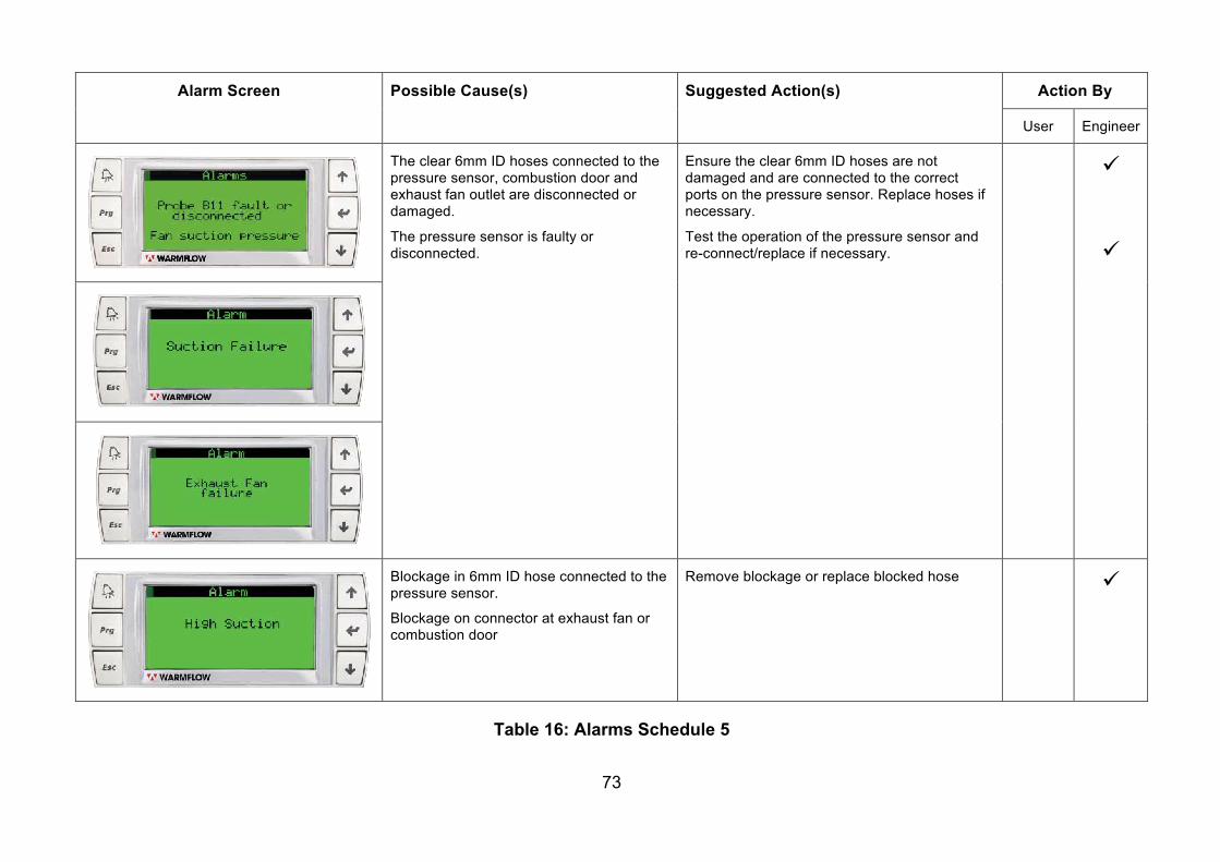
73
Alarm Screen Possible Cause(s) Suggested Action(s) Action By
User Engineer
The clear 6mm ID hoses connected to the pressure sensor, combustion door and exhaust fan outlet are disconnected or damaged.
The pressure sensor is faulty or disconnected.
Ensure the clear 6mm ID hoses are not damaged and are connected to the correct ports on the pressure sensor. Replace hoses if necessary.
Test the operation of the pressure sensor and re-connect/replace if necessary.
ü
ü
Blockage in 6mm ID hose connected to the pressure sensor.
Blockage on connector at exhaust fan or combustion door
Remove blockage or replace blocked hose ü
Table 16: Alarms Schedule 5
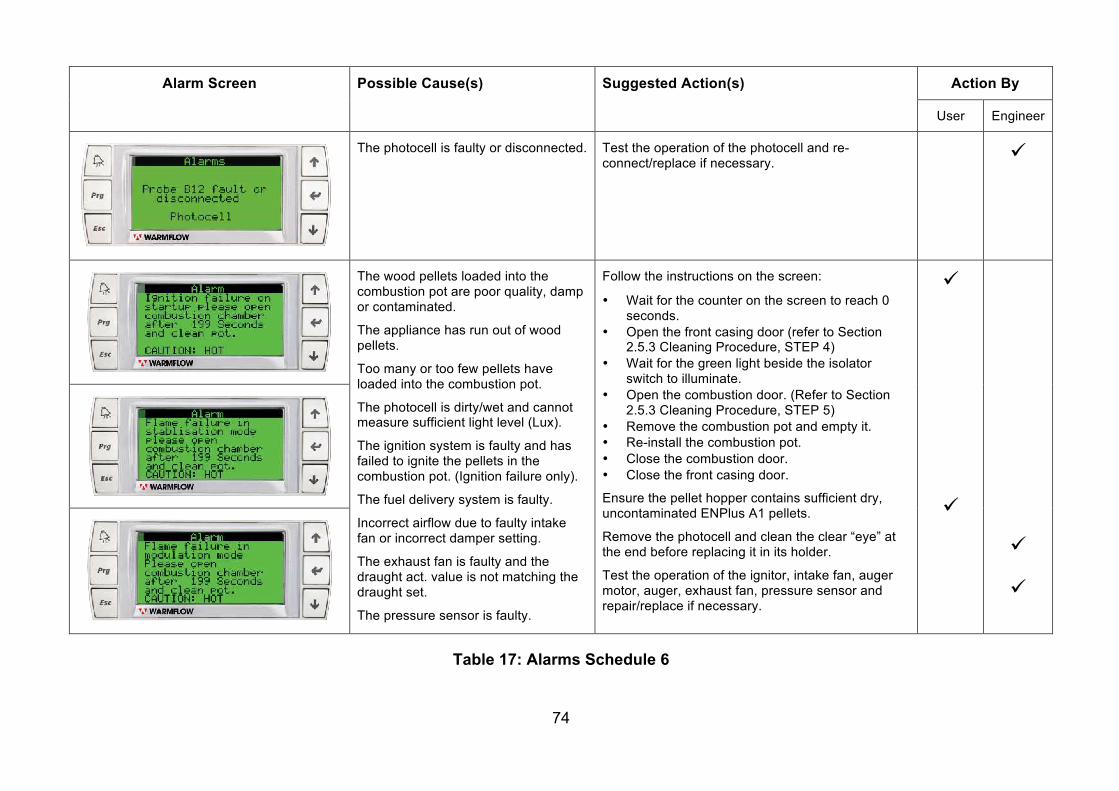
74
Alarm Screen Possible Cause(s) Suggested Action(s) Action By
User Engineer
The photocell is faulty or disconnected. Test the operation of the photocell and re-connect/replace if necessary. ü
The wood pellets loaded into the combustion pot are poor quality, damp or contaminated.
The appliance has run out of wood pellets.
Too many or too few pellets have loaded into the combustion pot.
The photocell is dirty/wet and cannot measure sufficient light level (Lux).
The ignition system is faulty and has failed to ignite the pellets in the combustion pot. (Ignition failure only).
The fuel delivery system is faulty.
Incorrect airflow due to faulty intake fan or incorrect damper setting.
The exhaust fan is faulty and the draught act. value is not matching the draught set.
The pressure sensor is faulty.
Follow the instructions on the screen:
• Wait for the counter on the screen to reach 0 seconds.
• Open the front casing door (refer to Section 2.5.3 Cleaning Procedure, STEP 4)
• Wait for the green light beside the isolator switch to illuminate.
• Open the combustion door. (Refer to Section 2.5.3 Cleaning Procedure, STEP 5)
• Remove the combustion pot and empty it. • Re-install the combustion pot. • Close the combustion door. • Close the front casing door.
Ensure the pellet hopper contains sufficient dry, uncontaminated ENPlus A1 pellets.
Remove the photocell and clean the clear “eye” at the end before replacing it in its holder.
Test the operation of the ignitor, intake fan, auger motor, auger, exhaust fan, pressure sensor and repair/replace if necessary.
ü
ü
ü
ü
Table 17: Alarms Schedule 6
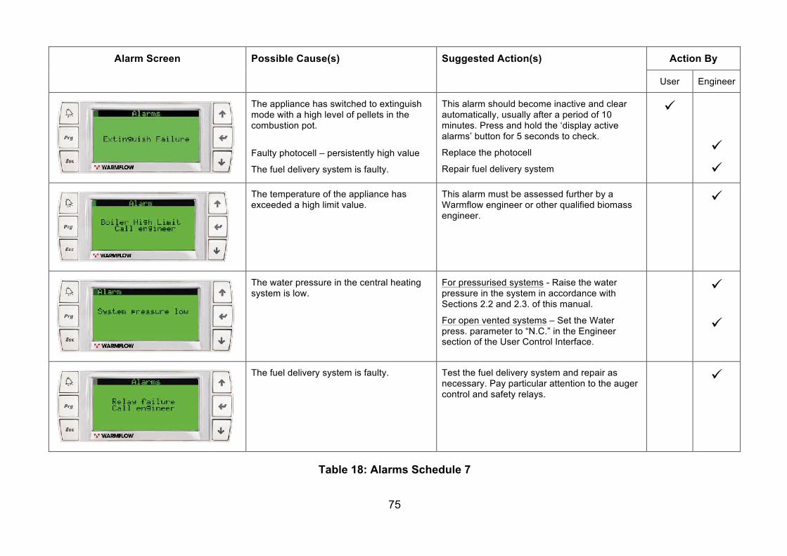
75
Alarm Screen Possible Cause(s) Suggested Action(s) Action By
User Engineer
The appliance has switched to extinguish mode with a high level of pellets in the combustion pot.
Faulty photocell – persistently high value
The fuel delivery system is faulty.
This alarm should become inactive and clear automatically, usually after a period of 10 minutes. Press and hold the ‘display active alarms’ button for 5 seconds to check.
Replace the photocell
Repair fuel delivery system
ü
ü ü
The temperature of the appliance has exceeded a high limit value.
This alarm must be assessed further by a Warmflow engineer or other qualified biomass engineer.
ü
The water pressure in the central heating system is low.
For pressurised systems - Raise the water pressure in the system in accordance with Sections 2.2 and 2.3. of this manual.
For open vented systems – Set the Water press. parameter to “N.C.” in the Engineer section of the User Control Interface.
ü
ü
The fuel delivery system is faulty. Test the fuel delivery system and repair as necessary. Pay particular attention to the auger control and safety relays.
ü
Table 18: Alarms Schedule 7
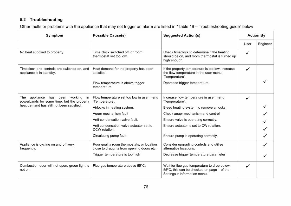
76
5.2 Troubleshooting Other faults or problems with the appliance that may not trigger an alarm are listed in “Table 19 – Troubleshooting guide” below
Symptom
Possible Cause(s) Suggested Action(s) Action By
User Engineer
No heat supplied to property. Time clock switched off, or room thermostat set too low.
Check timeclock to determine if the heating should be on, and room thermostat is turned up high enough.
ü
Timeclock and controls are switched on, and appliance is in standby.
Heat demand for the property has been satisfied.
Flow temperature is above trigger temperature.
If the property temperature is too low, increase the flow temperature in the user menu ‘Temperature’.
Decrease trigger temperature
ü
ü
The appliance has been working in powerbands for some time, but the property heat demand has still not been satisfied.
Flow temperature set too low in user menu ‘Temperature’.
Airlocks in heating system.
Auger mechanism fault
Anti-condensation valve fault.
Anti condensation valve actuator set to CCW rotation.
Circulating pump fault.
Increase flow temperature in user menu ‘Temperature’.
Bleed heating system to remove airlocks.
Check auger mechanism and control
Ensure valve is operating correctly.
Ensure actuator is set to CW rotation.
Ensure pump is operating correctly.
ü
ü ü ü ü ü
Appliance is cycling on and off very frequently.
Poor quality room thermostats, or location close to draughts from opening doors etc.
Trigger temperature is too high
Consider upgrading controls and utilise alternative locations.
Decrease trigger temperature parameter
ü
ü Combustion door will not open, green light is not on.
Flue gas temperature above 55°C. Wait for flue gas temperature to drop below 55⁰C, this can be checked on page 1 of the Settings > Information menu.
ü
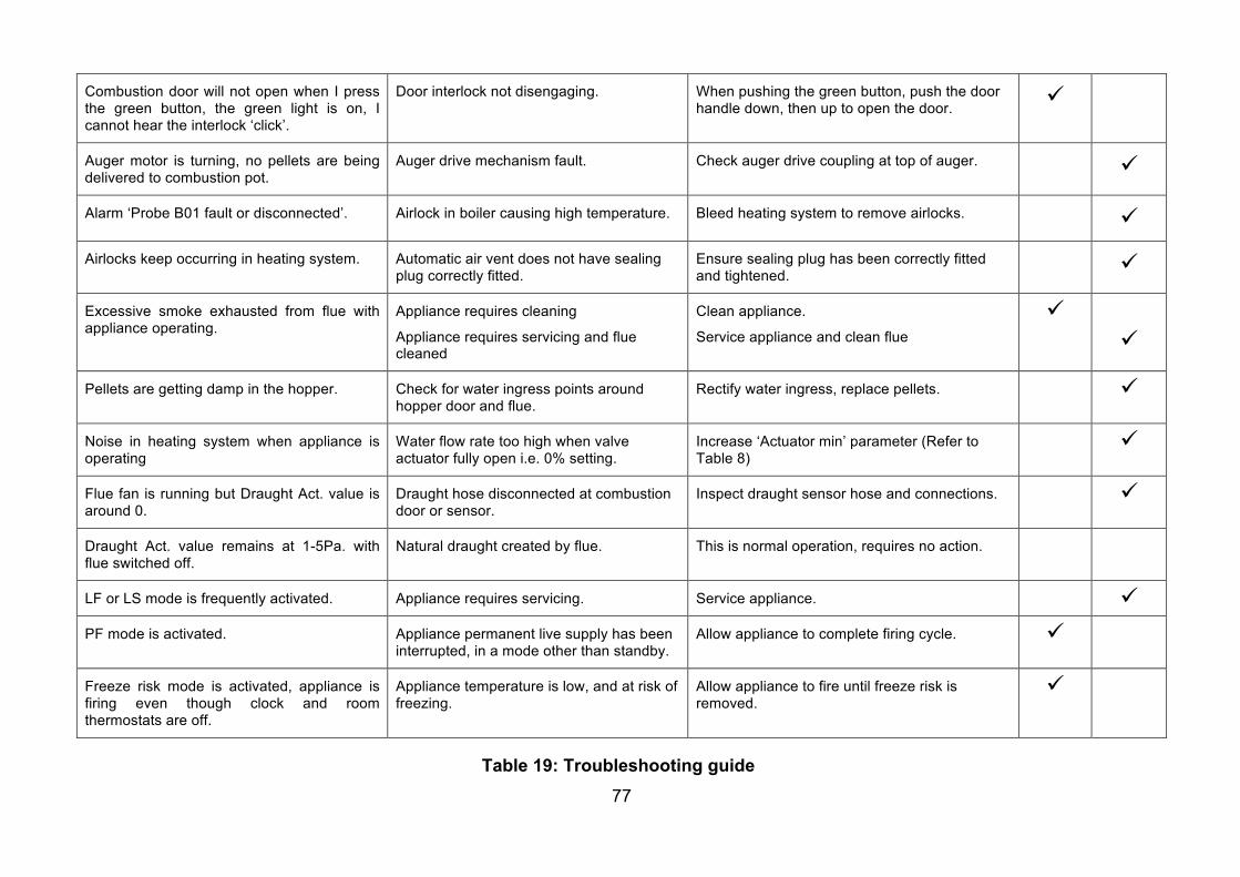
77
Combustion door will not open when I press the green button, the green light is on, I cannot hear the interlock ‘click’.
Door interlock not disengaging. When pushing the green button, push the door handle down, then up to open the door. ü
Auger motor is turning, no pellets are being delivered to combustion pot.
Auger drive mechanism fault. Check auger drive coupling at top of auger. ü
Alarm ‘Probe B01 fault or disconnected’. Airlock in boiler causing high temperature. Bleed heating system to remove airlocks. ü Airlocks keep occurring in heating system. Automatic air vent does not have sealing
plug correctly fitted. Ensure sealing plug has been correctly fitted and tightened. ü
Excessive smoke exhausted from flue with appliance operating.
Appliance requires cleaning
Appliance requires servicing and flue cleaned
Clean appliance.
Service appliance and clean flue ü
ü
Pellets are getting damp in the hopper. Check for water ingress points around hopper door and flue.
Rectify water ingress, replace pellets. ü
Noise in heating system when appliance is operating
Water flow rate too high when valve actuator fully open i.e. 0% setting.
Increase ‘Actuator min’ parameter (Refer to Table 8)
ü
Flue fan is running but Draught Act. value is around 0.
Draught hose disconnected at combustion door or sensor.
Inspect draught sensor hose and connections. ü
Draught Act. value remains at 1-5Pa. with flue switched off.
Natural draught created by flue. This is normal operation, requires no action.
LF or LS mode is frequently activated. Appliance requires servicing. Service appliance. ü PF mode is activated. Appliance permanent live supply has been
interrupted, in a mode other than standby. Allow appliance to complete firing cycle. ü
Freeze risk mode is activated, appliance is firing even though clock and room thermostats are off.
Appliance temperature is low, and at risk of freezing.
Allow appliance to fire until freeze risk is removed.
ü
Table 19: Troubleshooting guide
78
6 YOUR GUARANTEES, TERMS & CONDITIONS Periods of Guarantee Your wood pellet boiler (‘the Boiler’), including all controls, pipework & unions, associated equipment contained within the Boiler casing & flue system, if supplied by Warmflow, are guaranteed against defective parts and workmanship for a period of twenty four 24 months from the date of installation, provided that your Boiler is installed and commissioned in accordance with any instructions and recommendations of the manufacturer in force at the time of installation, and any other conditions of this warranty are met. This warranty includes labour for the first period of twelve (12) months.
The heat exchanger is guaranteed against defective parts and workmanship for a period of five (5) years from the date of installation, provided that your Boiler is installed and commissioned in accordance with any instructions and recommendations of the manufacturer in force at the time of installation, and any other conditions of this warranty are met. Please note that periods of guarantee will not be extended under any circumstances. Warmflow’s Obligations Where components are found to be defective in materials or workmanship within the periods set out above, Warmflow will arrange for repair or replacement as required. In the event that components are not capable of repair, Warmflow will provide replacement parts for any such components. Warmflow reserves the right to repair or replace components within the period of guarantee at a time and location that is most convenient to the company. All removed parts and components of your Boiler shall become the property of Warmflow. All replaced and/or repaired parts shall assume the status of the original part for the purposes of this warranty and this warranty shall not be extended by the replacement of such parts. This guarantee applies to Warmflow boilers installed in GB (including Scottish Isles), Isle of Man, Channel Islands, Northern Ireland and Republic of Ireland only. Provision of warranty cover elsewhere is subject to the agreement in writing of Warmflow.
79
Your Obligations
Your Boiler must be installed, commissioned and serviced in accordance with any instructions and recommendations of the manufacturer from time to time in force as may be communicated to you. In addition:
• The commissioning certificate in respect of your Boiler must be returned to Warmflow within thirty (30) days from the date of installation. Please note if your Boiler has not been installed within three (3) months of the date of dispatch from Warmflow, then this guarantee will be deemed to have commenced upon such date of dispatch. Please also note that failure to complete and return the commissioning certificate at the time of installation will invalidate all guarantees.
• Your Boiler must be installed and commissioned by an appropriately qualified person with suitable training* and experience, with commissioning completed immediately following installation.
• Your Boiler must be serviced by an appropriately qualified person with suitable training*
and experience twelve (12) months after the date of installation and thereafter at twelve (12) monthly intervals or sooner if required by the variable service schedule in the controller. Warmflow reserves the right to determine at its absolute discretion whether a person is appropriately qualified and has suitable training and experience.
• Each service record must be completed with proof of servicing retained and made available to Warmflow in respect of any claim.
• If you choose to have someone other than an appropriately qualified person with suitable training* and experience carry out works to your Boiler, this warranty will automatically become null and void.
• The pellets used in your Boiler must at all times comply with recognised industry
standards for wood pellets.(Currently ENPlus A1)
• The ash pan of your Boiler must be emptied as requested by the control screen or at least on a monthly basis and thoroughly cleaned in accordance with any instructions of the manufacturer from time to time in force as may be communicated to you.
* i.e. Warmflow product training course In the event of a breakdown please contact your commissioning engineer who should then contact our Customer care Department whilst at your home to report the fault.
80
PLEASE NOTE THAT FAILURE TO REGISTER AND ANNUALLY SERVICE THIS PRODUCT WILL INVALIDATE ALL GUARANTEES IN THEIR ENTIRETY Exclusions of Guarantee This guarantee is not transferable Parts The cleaning knives, ignitor, ash pan and combustion pot supplied with your Boiler are deemed to be consumable items and are therefore excluded from this guarantee. Scratches, nicks, minor dents, and cosmetic damages to external surfaces and exposed parts of your Boiler are also excluded. Repairs All repairs and/or replacements must be authorised in writing by Warmflow prior to any works being carried out. Warmflow will have no responsibility or liability for repairs or works performed by a person who has not been authorised by Warmflow. Warmflow will accept no liability for the cost of repairs resulting from incorrect installation, inadequate commissioning, lack of annual servicing, misuse, tampering or repair by persons who have not been authorised by Warmflow. Invoices for call out and/or repair by any third party or parts supplied by a third party will not be accepted unless previously authorised by Warmflow in writing. If you choose to have someone other than an authorised service provider carry out works to your Boiler, this warranty will automatically become null and void. Other property In no event shall Warmflow have any liability or responsibility whatsoever for damage to surrounding property and other structures or objects around your Boiler. General This warranty excludes all defects or damage that are not the direct fault of Warmflow, including without limitation, loss or damage caused by any one or more of the following:
(a) use of the Boiler in anything other than its normal and intended use; (b) Any repair that is needed as a result of anything other than a fault in the boiler or failure
of the boiler itself; (c) Any damage, whether accidental, negligent, malicious or otherwise; (d) Any fault or failure in the heating system to which the boiler is connected; (e) Any other costs or expenses caused by, or arising as a result of, a repair; (f) any fault or failure in the boiler caused by a fault, failure or defect in the heating system
to which the boiler is connected (g) any party’s wilful misconduct, negligence, misuse, abuse, accidents, improper operation,
failure to maintain, improper or negligent installation, tampering, failure to follow operating instructions, mishandling, unauthorized service;
(h) adjustment, alteration or modification of the Boiler of any kind; (i) ordinary wear and tear; and
81
(j) any external forces and factors, including without limitation, lightning strikes, fire, floods, rain, freezing, excessive moisture or extended exposure to humidity, power surges, and acts of God.
(k) Any defects that appear after the customer makes any modification or alteration to the boiler;
(l) Defects caused by the improper use or storage of the boiler and in particular (but without limitation) Warmflow shall not be liable in the case of defects arising from normal deterioration or improper or faulty handling or processing of the boiler by the customer;
(m) Any problems caused by inadequate supply of services such as electricity or water to the property;
Claims for consequential loss or damage however caused are not covered by this guarantee. Please note that your statutory rights are not affected by this guarantee.
82
7 APPLIANCE INSTALLATION/COMMISSIONING CERTIFICATE & REGISTRATION.
Instructions. • Complete the Installation/Commissioning Certificate.
• Complete the Installation/Commissioning Certificate overleaf.
• Fill out all relevant sections of the Installation/Commissioning Certificate using BLOCK CAPITALS. Please write legibly.
• Ensure that the certificate is signed by both the Competent Person and the Customer.
• Carbon copies of the certificate are produced automatically.
• Register the Appliance.
• Remove the white copy of the Installation/Commissioning Certificate.
• Send the certificate to Warmflow
- By post using the envelope provided to:
Warmflow Engineering Co. Ltd. Lissue Industrial Estate Moira Road Lisburn Co. Antrim Northern Ireland BT28 2RF OR
- By fax on 02892620869
If the appliance is not registered, warranty may be invalidated.
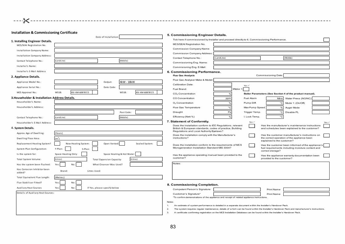
83
Installation&CommissioningCertificateDateofInsta l lation:
1.InstallingEngineerDetails.MCS/SEAIRegis trationNo.
Insta l lationCompanyName:
Insta l lationCompanyAddress :
ContactTelephoneNo.: (LandLine) (Mobile)
Insta l ler’s Name:
Insta l ler's E-Mai l Address
2.ApplianceDetails.Appl ianceModel No.: Output:
Appl ianceSeria l No.: DateCode:
MCSApproval No.: WS18: BSIKM608787/2 WS18: BSIKM608787/2
3.Householder&InstallationAddressDetails.Householder’s Name:
Householder’s Address :
PostCode:
ContactTelephoneNo.: (LandLine) (Mobile)
Householder’s E-Mai l Address :
4. SystemDetails.
Approx.AgeofDwel l ing: (Years )
Dwel l ingFloorArea: (m2)
ReplacementHeatingSystem? NewHeatingSystem: OpenVented: SealedSystem:
SystemPlanConfiguration: Y-Plan: S-Plan:
Is thesystemfor: SpaceHeatingOnly: SpaceHeating&HotWater:
Tota l SystemVolume: (Litres) Tota l Expans ionCapaci ty: (Litres)
Has thesystembeenflushed: Yes : No: WhatCleanserWas Used?
Has Corros ionInhibi torbeenadded?
Brand: Li tres Used:
Tota l Equiva lentFlueLength: (Metres)
FlueStabi l i serFi tted? Yes : No:
Auxi l iaryHeatSources Yes : No: IfYes ,pleasespeci fybelow
4kW-18kW
Detai l s ofAuxi l iaryHeatSources :
5.Commissioning Engineer Details.Tick here if commissioned by Installer and proceed directly to 6. Commissioning Performance.
MCS/SEAI Registration No.
Commission Company Name:
Commission Company Address:
Contact Telephone No.: (LandLine) (Mobile)
Commissioning Eng. Name:
Commisioning Eng. E-Mail:
6.Commissioning Performance.Flue Gas Analysis Commissioning Date:
Flue Gas Analyser Make & Model:
Calibration Date:
Fuel Brand: ENplus 1:
CO2 Concentration % Boiler Parameters (See Section 4 of the product manual).
CO Concentration ppm Fuel Alarm Mins Water Press (NO/NC)
O2 Concentration % Pump Diff. °C Mode 1: (On/Off)
Flue Gas Temperature °C Max Pump Speed % Auger Mode
Draught Pa Trigger Temp. °C Disable PL
Efficiency (Nett %) % I. Lock Temp. °C
7. Statement of Conformity.
Notes:
8. Commissioning Completion.Competent Person’s Signature: Print Name
Customer’s Signature* Print Name*To confirm demonstrations of the appliance and receipt of related appliance instructions.
Notes:
1. An estimate of system performance is detailed in a separate document w ithin the Installer’s Handover Pack.
2. The system requires regular maintenance, details of w hich can be found w ithin the Installer’s Handover Pack and manufacturer’s instructions.
3. A certif icate confirming registration on the MCS Installation Database can be found w ithin the Installer’s Handover Pack.
Has the manufacturer’s maintenance instructions and schedules been explained to the customer?
Does the installation comply with the Manufacturer’s instructions?
Does the installation conform to the requirements of MCS Microgeneration Installation Standard MIS 3004?
Has the appliance operating manual been provided to the customer?
Has the customer manufacturer’s instructions on the correct operation of the appliance been explained to the customer?
Has the customer been informed of the appliance’s fuel requirements including moisture content and correct storage?
Has the appliance warranty documentation been provided to the customer?
Does the installation conform to IEE Regulations, relevant British & European standards, codes of practice, Building Regulations and Local Authority Byelaws?
YesP
YesP YesP
&

84
INTENTIONALLY LEFT BLANK
8 APPLIANCE SERVICE RECORDS. Instructions.
• The appliance must be serviced in accordance with the service schedule and instructions laid out in this manual.
• Details of the service conducted must be fully recorded on the following service record sheets by the Warmflow or other qualified biomass engineer conducting the service.
• Service records must be retained for inspection upon request by the manufacturer.
• All product warranties will be invalidated if the appliance is not serviced at least annually or as indicated by the user interface controller by a Warmflow engineer or other trained and competent Engineer and details recorded in the service record section of this manual.

86
PLEASE COMPLETE USING BLOCK CAPITALS.
Service Record 1 Date of Servicing:
1. Service Engineer Details MCS/SEAI Registration No.
Service Company Name: Service Company Address: Contact Telephone No.: Service Engineer’s Name: Service Engineer’s Email:
2. Appliance Servicing Checklist All steps of servicing procedure in WS18/WP18 Technical Manual completed?
Yes No Details of additional service items included:
3. System Modifications Since Last Service. Have there been any modifications made to the heating system since the last service? For example: additional
radiators, additional domestic hot water needs, addition of auxiliary heat sources.
Yes No If Yes, Details of Modifications:
4. After Service Performance. Flue Gas Analyser Make and Model Calibration Date: Yes ü Fuel Brand: EN Plus A1?: CO2 Concentration (%) NOTES CO Concentration (ppm) O2 Concentration (%) Flue Gas Temperature (⁰C) Draught (Pa) Efficiency (Nett %)
5. Service Completion Engineer’s Signature Print Name
Customer’s Signature* Print Name * To confirm demonstration of appliance servicing and receipt of this service record

87
PLEASE COMPLETE USING BLOCK CAPITALS.
Service Record 2 Date of Servicing:
1. Service Engineer Details MCS/SEAI Registration No.
Service Company Name: Service Company Address: Contact Telephone No.: Service Engineer’s Name: Service Engineer’s Email:
2. Appliance Servicing Checklist All steps of servicing procedure in WS18/WP18 Technical Manual completed?
Yes No Details of additional service items included:
3. System Modifications Since Last Service. Have there been any modifications made to the heating system since the last service? For example: additional
radiators, additional domestic hot water needs, addition of auxiliary heat sources.
Yes No If Yes, Details of Modifications:
4. After Service Performance. Flue Gas Analyser Make and Model Calibration Date: Yes ü Fuel Brand: EN Plus A1?: CO2 Concentration (%) NOTES CO Concentration (ppm) O2 Concentration (%) Flue Gas Temperature (⁰C) Draught (Pa) Efficiency (Nett %)
5. Service Completion Engineer’s Signature Print Name
Customer’s Signature* Print Name * To confirm demonstration of appliance servicing and receipt of this service record

88
PLEASE COMPLETE USING BLOCK CAPITALS.
Service Record 3 Date of Servicing:
1. Service Engineer Details MCS/SEAI Registration No.
Service Company Name: Service Company Address: Contact Telephone No.: Service Engineer’s Name: Service Engineer’s Email:
2. Appliance Servicing Checklist All steps of servicing procedure in WS18/WP18 Technical Manual completed?
Yes No Details of additional service items included:
3. System Modifications Since Last Service. Have there been any modifications made to the heating system since the last service? For example: additional
radiators, additional domestic hot water needs, addition of auxiliary heat sources.
Yes No If Yes, Details of Modifications:
4. After Service Performance. Flue Gas Analyser Make and Model Calibration Date: Yes ü Fuel Brand: EN Plus A1?: CO2 Concentration (%) NOTES CO Concentration (ppm) O2 Concentration (%) Flue Gas Temperature (⁰C) Draught (Pa) Efficiency (Nett %)
5. Service Completion Engineer’s Signature Print Name
Customer’s Signature* Print Name * To confirm demonstration of appliance servicing and receipt of this service record

89
PLEASE COMPLETE USING BLOCK CAPITALS.
Service Record 4 Date of Servicing:
1. Service Engineer Details MCS/SEAI Registration No.
Service Company Name: Service Company Address: Contact Telephone No.: Service Engineer’s Name: Service Engineer’s Email:
2. Appliance Servicing Checklist All steps of servicing procedure in WS18/WP18 Technical Manual completed?
Yes No Details of additional service items included:
3. System Modifications Since Last Service. Have there been any modifications made to the heating system since the last service? For example: additional
radiators, additional domestic hot water needs, addition of auxiliary heat sources.
Yes No If Yes, Details of Modifications:
4. After Service Performance. Flue Gas Analyser Make and Model Calibration Date: Yes ü Fuel Brand: EN Plus A1?: CO2 Concentration (%) NOTES CO Concentration (ppm) O2 Concentration (%) Flue Gas Temperature (⁰C) Draught (Pa) Efficiency (Nett %)
5. Service Completion Engineer’s Signature Print Name
Customer’s Signature* Print Name * To confirm demonstration of appliance servicing and receipt of this service record

90
PLEASE COMPLETE USING BLOCK CAPITALS.
Service Record 5 Date of Servicing:
1. Service Engineer Details MCS/SEAI Registration No.
Service Company Name: Service Company Address: Contact Telephone No.: Service Engineer’s Name: Service Engineer’s Email:
2. Appliance Servicing Checklist All steps of servicing procedure in WS18/WP18 Technical Manual completed?
Yes No Details of additional service items included:
3. System Modifications Since Last Service. Have there been any modifications made to the heating system since the last service? For example: additional
radiators, additional domestic hot water needs, addition of auxiliary heat sources.
Yes No If Yes, Details of Modifications:
4. After Service Performance. Flue Gas Analyser Make and Model Calibration Date: Yes ü Fuel Brand: EN Plus A1?: CO2 Concentration (%) NOTES CO Concentration (ppm) O2 Concentration (%) Flue Gas Temperature (⁰C) Draught (Pa) Efficiency (Nett %)
5. Service Completion Engineer’s Signature Print Name
Customer’s Signature* Print Name * To confirm demonstration of appliance servicing and receipt of this service record

91
PLEASE COMPLETE USING BLOCK CAPITALS.
Service Record 6 Date of Servicing:
1. Service Engineer Details MCS/SEAI Registration No.
Service Company Name: Service Company Address: Contact Telephone No.: Service Engineer’s Name: Service Engineer’s Email:
2. Appliance Servicing Checklist All steps of servicing procedure in WS18/WP18 Technical Manual completed?
Yes No Details of additional service items included:
3. System Modifications Since Last Service. Have there been any modifications made to the heating system since the last service? For example: additional
radiators, additional domestic hot water needs, addition of auxiliary heat sources.
Yes No If Yes, Details of Modifications:
4. After Service Performance. Flue Gas Analyser Make and Model Calibration Date: Yes ü Fuel Brand: EN Plus A1?: CO2 Concentration (%) NOTES CO Concentration (ppm) O2 Concentration (%) Flue Gas Temperature (⁰C) Draught (Pa) Efficiency (Nett %)
5. Service Completion Engineer’s Signature Print Name
Customer’s Signature* Print Name * To confirm demonstration of appliance servicing and receipt of this service record

92
PLEASE COMPLETE USING BLOCK CAPITALS.
Service Record 7 Date of Servicing:
1. Service Engineer Details MCS/SEAI Registration No.
Service Company Name: Service Company Address: Contact Telephone No.: Service Engineer’s Name: Service Engineer’s Email:
2. Appliance Servicing Checklist All steps of servicing procedure in WS18/WP18 Technical Manual completed?
Yes No Details of additional service items included:
3. System Modifications Since Last Service. Have there been any modifications made to the heating system since the last service? For example: additional
radiators, additional domestic hot water needs, addition of auxiliary heat sources.
Yes No If Yes, Details of Modifications:
4. After Service Performance. Flue Gas Analyser Make and Model Calibration Date: Yes ü Fuel Brand: EN Plus A1?: CO2 Concentration (%) NOTES CO Concentration (ppm) O2 Concentration (%) Flue Gas Temperature (⁰C) Draught (Pa) Efficiency (Nett %)
5. Service Completion Engineer’s Signature Print Name
Customer’s Signature* Print Name * To confirm demonstration of appliance servicing and receipt of this service record
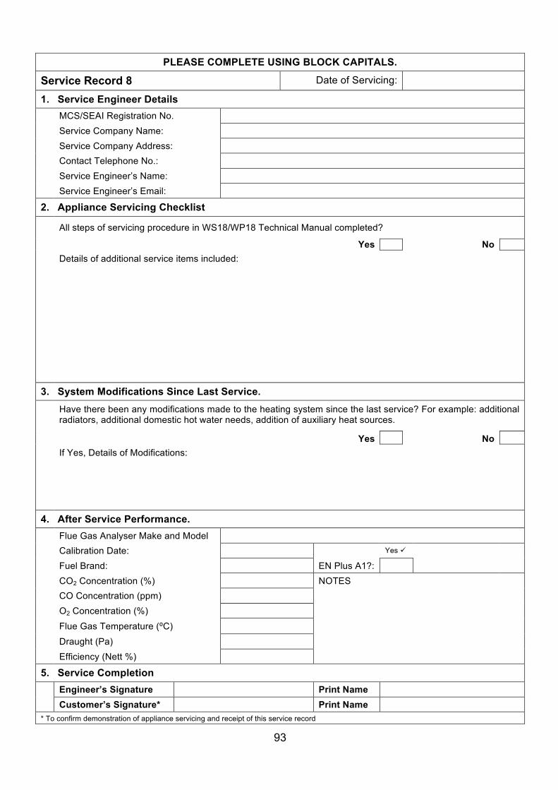
93
PLEASE COMPLETE USING BLOCK CAPITALS.
Service Record 8 Date of Servicing:
1. Service Engineer Details MCS/SEAI Registration No.
Service Company Name: Service Company Address: Contact Telephone No.: Service Engineer’s Name: Service Engineer’s Email:
2. Appliance Servicing Checklist All steps of servicing procedure in WS18/WP18 Technical Manual completed?
Yes No Details of additional service items included:
3. System Modifications Since Last Service. Have there been any modifications made to the heating system since the last service? For example: additional
radiators, additional domestic hot water needs, addition of auxiliary heat sources.
Yes No If Yes, Details of Modifications:
4. After Service Performance. Flue Gas Analyser Make and Model Calibration Date: Yes ü Fuel Brand: EN Plus A1?: CO2 Concentration (%) NOTES CO Concentration (ppm) O2 Concentration (%) Flue Gas Temperature (⁰C) Draught (Pa) Efficiency (Nett %)
5. Service Completion Engineer’s Signature Print Name
Customer’s Signature* Print Name * To confirm demonstration of appliance servicing and receipt of this service record

94
PLEASE COMPLETE USING BLOCK CAPITALS.
Service Record 9 Date of Servicing:
1. Service Engineer Details MCS/SEAI Registration No.
Service Company Name: Service Company Address: Contact Telephone No.: Service Engineer’s Name: Service Engineer’s Email:
2. Appliance Servicing Checklist All steps of servicing procedure in WS18/WP18 Technical Manual completed?
Yes No Details of additional service items included:
3. System Modifications Since Last Service. Have there been any modifications made to the heating system since the last service? For example: additional
radiators, additional domestic hot water needs, addition of auxiliary heat sources.
Yes No If Yes, Details of Modifications:
4. After Service Performance. Flue Gas Analyser Make and Model Calibration Date: Yes ü Fuel Brand: EN Plus A1?: CO2 Concentration (%) NOTES CO Concentration (ppm) O2 Concentration (%) Flue Gas Temperature (⁰C) Draught (Pa) Efficiency (Nett %)
5. Service Completion Engineer’s Signature Print Name
Customer’s Signature* Print Name * To confirm demonstration of appliance servicing and receipt of this service record

95
PLEASE COMPLETE USING BLOCK CAPITALS.
Service Record 10 Date of Servicing:
1. Service Engineer Details MCS/SEAI Registration No.
Service Company Name: Service Company Address: Contact Telephone No.: Service Engineer’s Name: Service Engineer’s Email:
2. Appliance Servicing Checklist All steps of servicing procedure in WS18/WP18 Technical Manual completed?
Yes No Details of additional service items included:
3. System Modifications Since Last Service. Have there been any modifications made to the heating system since the last service? For example: additional
radiators, additional domestic hot water needs, addition of auxiliary heat sources.
Yes No If Yes, Details of Modifications:
4. After Service Performance. Flue Gas Analyser Make and Model Calibration Date: Yes ü Fuel Brand: EN Plus A1?: CO2 Concentration (%) NOTES CO Concentration (ppm) O2 Concentration (%) Flue Gas Temperature (⁰C) Draught (Pa) Efficiency (Nett %)
5. Service Completion Engineer’s Signature Print Name
Customer’s Signature* Print Name * To confirm demonstration of appliance servicing and receipt of this service record

96
9 APPENDIX A – SUPPLEMENTARY INSTALLATION AND OPERATING INSTRUCTIONS FOR THE UK MARKET
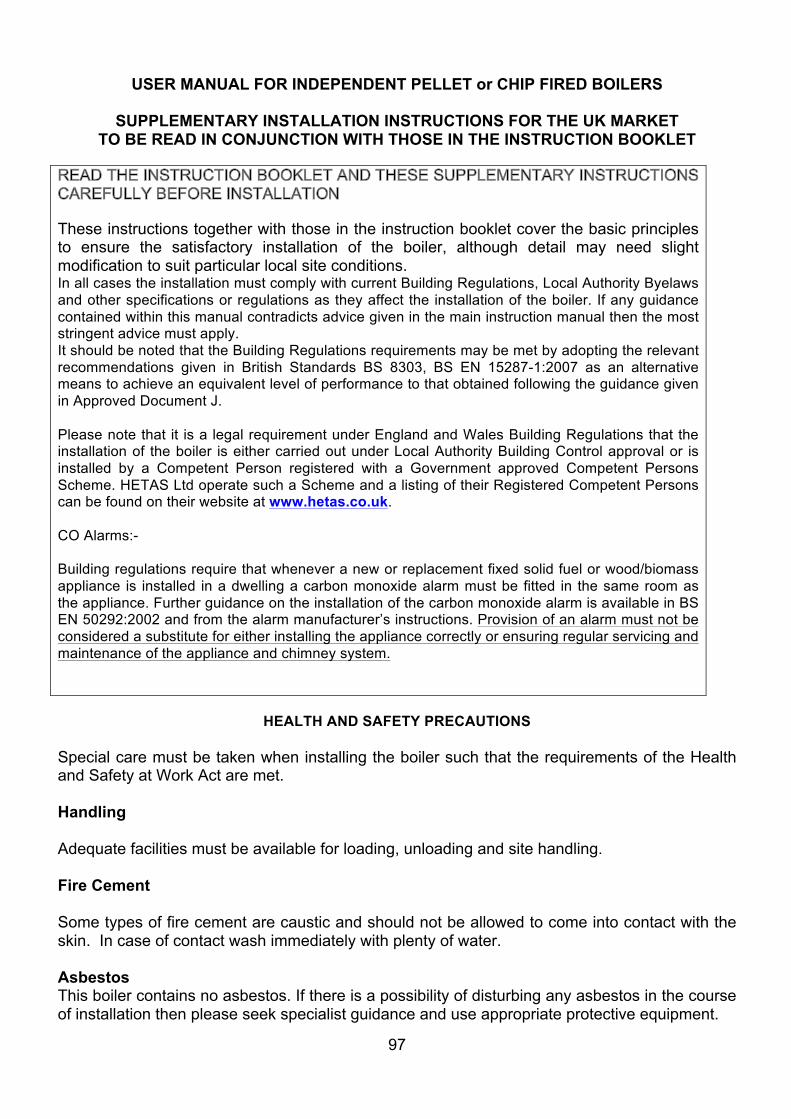
97
USER MANUAL FOR INDEPENDENT PELLET or CHIP FIRED BOILERS
SUPPLEMENTARY INSTALLATION INSTRUCTIONS FOR THE UK MARKET TO BE READ IN CONJUNCTION WITH THOSE IN THE INSTRUCTION BOOKLET
These instructions together with those in the instruction booklet cover the basic principles to ensure the satisfactory installation of the boiler, although detail may need slight modification to suit particular local site conditions. In all cases the installation must comply with current Building Regulations, Local Authority Byelaws and other specifications or regulations as they affect the installation of the boiler. If any guidance contained within this manual contradicts advice given in the main instruction manual then the most stringent advice must apply. It should be noted that the Building Regulations requirements may be met by adopting the relevant recommendations given in British Standards BS 8303, BS EN 15287-1:2007 as an alternative means to achieve an equivalent level of performance to that obtained following the guidance given in Approved Document J. Please note that it is a legal requirement under England and Wales Building Regulations that the installation of the boiler is either carried out under Local Authority Building Control approval or is installed by a Competent Person registered with a Government approved Competent Persons Scheme. HETAS Ltd operate such a Scheme and a listing of their Registered Competent Persons can be found on their website at www.hetas.co.uk. CO Alarms:- Building regulations require that whenever a new or replacement fixed solid fuel or wood/biomass appliance is installed in a dwelling a carbon monoxide alarm must be fitted in the same room as the appliance. Further guidance on the installation of the carbon monoxide alarm is available in BS EN 50292:2002 and from the alarm manufacturer’s instructions. Provision of an alarm must not be considered a substitute for either installing the appliance correctly or ensuring regular servicing and maintenance of the appliance and chimney system.
HEALTH AND SAFETY PRECAUTIONS Special care must be taken when installing the boiler such that the requirements of the Health and Safety at Work Act are met. Handling Adequate facilities must be available for loading, unloading and site handling. Fire Cement Some types of fire cement are caustic and should not be allowed to come into contact with the skin. In case of contact wash immediately with plenty of water. Asbestos This boiler contains no asbestos. If there is a possibility of disturbing any asbestos in the course of installation then please seek specialist guidance and use appropriate protective equipment.
98
Metal Parts When installing or servicing this boiler care should be taken to avoid the possibility of personal injury.
BOILER PERFORMANCE Refer to the main instruction manual for details of the boiler’s performance.
PREPARATORY WORK AND SAFETY CHECKS
IMPORTANT WARNING This boiler must not be installed into a chimney that serves any other heating appliance. There must not be an extractor fan fitted in the same room as the boiler as this can cause the boiler to emit fumes into the room. Chimney In order for the boiler to perform satisfactorily the chimney height must be sufficient to ensure an adequate draught of approximately 15 Pa so as to clear the products of combustion and prevent smoke problems into the room. NOTE: A chimney height of not less than 4.5 metres measured vertically from the outlet of the boiler to the top of the chimney should be satisfactory. Alternatively the calculation procedure given in EN 13384-1 may be used as the basis for deciding whether a particular chimney design will provide sufficient draught. The outlet from the chimney should be above the roof of the building in accordance with the provisions of Building Regulations Approved Document J. Because the boiler runs at high efficiencies, the temperature of the flue gases is at times lower than conventional solid fuel appliances. Although it is not classed as a condensing appliance, the low flue gas temperature results in condensation occurring within the flue. Any chimney flue system must therefore be able to withstand the effects of condensate and operate under wet conditions (designation letter W). In addition it should be soot fire resistant and able to withstand the corrosive effects of flue products generated by solid fuels (designation G and 3 respectively). If installation is into an existing masonry chimney then it will require re-lining with a liner meeting the specification described above. Existing concrete or clay lined chimneys are not suitable for this boiler and must be lined as described above. All installations must be in accordance with Building Regulations Approved Document J. Any existing chimney must be clear of obstruction and have been swept clean immediately before installation of the lining system. Where the chimney is believed to have previously served an open fire installation it is possible that the higher flue gas temperature from a closed appliance may loosen deposits that were previously firmly adhered, with the consequent risk of flue blockage. It is therefore recommended that the chimney be swept a second time within a month of regular use after installation.
99
If there is no existing chimney then any new system must be to the designation described above and in accordance with Building Regulations Approved Document J. A single wall metal fluepipe is suitable for connecting the boiler to the chimney but is not suitable for use as the complete chimney. The chimney and connecting fluepipe must have a minimum diameter of 150 mm and its dimension should be not less than the size of the outlet socket of the boiler. Any bend in the chimney or connecting fluepipe should not exceed 45°. 90° bends should not be used. Combustible material should not be located where the heat dissipating through the walls of fireplaces or flues could ignite it. Therefore when installing the boiler in the presence of combustible materials due account must be taken of the guidance on the separation of combustible material given in Building Regulations Approved Document J and also in these boiler instructions. If it is found that there is excessive draught in the chimney then a draught stabiliser should be fitted in the chimney above the chimney above the flue pipe connection. Fitting of a draught stabiliser will affect the requirement for the permanent air supply into the room in which the boiler is fitted in accordance with Approved Document J (see also combustion air supply). Adequate provision e.g. easily accessible soot door or doors must be provided for sweeping the chimney and connecting fluepipe. Hearth The hearth should be able to accommodate the weight of the boiler and its chimney if the chimney is not independently supported. The weight of the boiler is indicated in the brochure. The boiler should preferably be installed on a non-combustible hearth of a size and construction that is in accordance with the provisions of the current Building Regulations Approved Document J. The clearance distances to combustible material beneath, surrounding or upon the hearth and walls adjacent to the hearth should comply with the guidance on the separation of combustible material given in Building Regulations Approved Document J and also in these boiler instructions. If the boiler is to be installed on a combustible floor surface, it must be covered with a non-combustible material at least 12mm thick, in accordance with Building Regulations Approved Document J, to a distance of 30 cm in front of the boiler and 15 cm to each side measuring from the door of the combustion chamber. Combustion air supply In order for the boiler to perform efficiently and safely there must be an adequate air supply into the room in which the boiler is installed to provide combustion air. The provision of air supply to the boiler must be in accordance with current Building Regulations Approved Document J. An opening window is not appropriate for this purpose.
100
Connection to chimney All the boilers have a flue gas connector that allows connection to either a masonry chimney or a prefabricated factory made insulated metal chimney in accordance with the instructions. This connection should never be reduced in diameter to lower than that of the flue gas connector of the boiler. In some cases it may be necessary to fit an adapter in the connection pipe to increase the diameter to the required minimum diameter of 150 mm for burning wood fuel in accordance with UK regulations. Any connections should be made gas-tight and sealed with a suitable sealing agent such as fire cement. Connection to the central heating system The boilers may be installed on either open vented or sealed fully pumped systems and a double-feed indirect cylinder to BS 1566 is necessary where there is a combined hot water and central heating system. Please ensure that a gravity heat-leak radiator/towel rail or equivalent is used to dissipate heat in the system when the pump is off if required. The central heating system must be in accordance with BS EN 14336:2004: Heating Systems in Buildings. Installation and commissioning of water based heating systems. BS EN 12828: 2003; Heating Systems in Buildings. Design of water based heating systems. BS EN 12831: 2003; Heating Systems in Buildings. Method for calculation of the design heat load and BS 6880:1988 Parts 1 to 3, Code of Practice for low temperature hot water heating systems of output greater than 45kW where appropriate. Electrical connections The installation of any electrical services during the installation of this boiler and the associated heating system must be carried out by a registered competent electrician and in accordance with the requirements of the latest issue of BS 7671. Commissioning and handover Ensure all parts are fitted in accordance with the instructions. On completion of the installation allow a suitable period of time for any fire cement and mortar to dry out, before lighting the boiler. Once the boiler is under fire check all seals for soundness and that the boiler and water system are operating correctly. Ensure that the flue is functioning correctly and that all products of combustion are vented safely to atmosphere via the chimney terminal. On completion of the installation and commissioning ensure that the operating instructions for the boiler are left with the customer. Ensure to advise the customer on the correct use of the appliance and warn them to use only the recommended fuel for the boiler. Advise the user what to do should smoke or fumes be emitted from the boiler. The customer should be advised about restricting access to the boiler by children, aged and/or infirm people. Important Note: In the event of the appliance failing to light after the initial ignition light-up process, please switch off the appliance immediately and contact the manufacturer for guidance. Please do not attempt to re-light the boiler until the issue has been resolved.
101
USER MANUAL FOR INDEPENDENT PELLET or CHIP FIRED BOILERS
SUPPLEMENTARY OPERATING INSTRUCTIONS FOR THE UK MARKET TO BE READ IN CONJUNCTION WITH THOSE IN THE INSTRUCTION BOOKLET
WARNING NOTE Properly installed, operated and maintained this stove will not emit fumes into the dwelling. Occasional fumes from de-ashing and re-fuelling may occur. However, persistent fume emission is potentially dangerous and must not be tolerated. If fume emission does persist, then the following immediate action should be taken: - (a) Open doors and windows to ventilate the room and then leave the premises. (b) Let the fire go out. (c) Check for flue or chimney blockage and clean if required (d) Do not attempt to relight the fire until the cause of the fume emission has been identified and corrected. If necessary seek expert advice. The most common cause of fume emission is flueway or chimney blockage. For your own safety these must be kept clean at all times.
IMPORTANT NOTES
General Before lighting the boiler check with the installer that the installation work and commissioning checks described above have been carried out correctly and that the chimney has been swept clean, is sound and free from any obstructions. As part of the boilers’ commissioning and handover the installer should have shown you how to operate the boiler correctly. Do not light the boiler if there is a possibility that any part of the heating system may be frozen Please make sure the ash-pit door and the hopper lid/charging door are firmly closed at all times whilst the boiler is in operation. In the event of the appliance failing to light after the initial ignition light-up process, please switch off the appliance immediately and contact a qualified engineer for resolution of the issue. Please do not attempt to re-light the boiler until the issue has been signed off by the engineer. CO Alarm Your installer should have fitted a CO alarm in the same room as the appliance. If the alarm sounds unexpectedly, follow the instructions given under “Warning Note” above.
102
Boiler Access Access to the boiler should be restricted for children, aged and/or infirm persons by way of a lockable door to the room in which the boiler is installed. Chimney cleaning The chimney should be swept at least twice a year. It is important that the flue connection and chimney are swept prior to lighting up after a prolonged shutdown period. Where the chimney is believed to have a served an open fire installation it is possible that the higher flue gas temperature from a closed appliance may loosen deposits that were previously firmly adhered, with the consequent risk of flue blockage. It is therefore recommended that the chimney be swept a second time within a month of regular use after installation. In situations where it is not possible to sweep through the boiler the installer will have provided alternative means, such as a soot door. After sweeping the chimney the boiler flue outlet and the flue pipe connecting the boiler to the chimney must be cleaned with a flue brush. Periods of Prolonged Non-Use If the boiler is to be left unused for a prolonged period of time then it should be given a thorough clean to remove ash and unburned fuel residues. Empty the hopper of unburned fuel. To enable a good flow of air through the appliance to reduce condensation and to avoid door seals becoming stuck and subsequently damaged, leave the filling hatch and combustion chamber doors slightly ajar. These actions will reduce the possibility of unnecessary damage and corrosion. Extractor fan There must not be an extractor fan fitted in the same room as the boiler as this can cause the boiler to emit smoke and fumes into the room Aerosol sprays Do not use an aerosol spray on or near the boiler when it is alight. Use of operating tools Always use the operating tools provided when handling parts likely to be hot when the boiler is in use. Chimney Fires If the chimney is thoroughly and regularly swept, chimney fires should not occur. However, if a chimney fire does occur turn off the boiler immediately and isolate the mains electricity supply, and tightly close the doors of the boiler. This should cause the chimney fire to go out. If the chimney fire does not go out when the above action is taken then the fire brigade should be called immediately. Do not relight the boiler until the chimney and flueway have been cleaned and examined by a professional.
103
Permanent air vent The boiler requires a permanent and adequate air supply in order for it to operate safely and efficiently. In accordance with current Building Regulations the installer may have fitted a permanent air supply vent into the room in which the boiler is installed to provide combustion air. This air vent should not under any circumstances be shut off or sealed.
USER OPERATING INSTRUCTIONS Please read the important notices given above before referring to the main instruction book for detailed operating instructions. Frequency of cleaning ash and residues from combustion chamber and ash-box The owner is required to regularly carry out this cleaning operation and the frequency will depend on the heating load. When first put to use the boiler should be checked on a daily basis and experience will show how often this will eventually be required. Remember also that during the main heating season the cleaning interval will shorten as the load on the boiler will be higher. Recommended fuels The boiler is designed to burn only specialized either compressed wood pellets or wood chips which are detailed in the main instruction book. Under no circumstances should you attempt to burn any other type of fuel. General Maintenance It is important that any glass or other decorative surfaces are kept clean using the appropriate cleaning materials and techniques as to not damage the internal or external finishes of the boiler. Spare Parts For more information on obtaining spare parts, please revert to the specific page of the manufacturer’s original instruction manual or contact details provided. HETAS Ltd Approval This appliance has obtained HETAS Ltd approval for burning either compressed wood pellets or wood chips as specified in the main instruction manual. Approval does not cover the use of other fuels either alone or mixed with the recommended fuel, nor does it cover instructions for the use of other fuels.

104
10 APPENDIX B – CUSTOMER CONNECTION WIRING SCHEMATIC
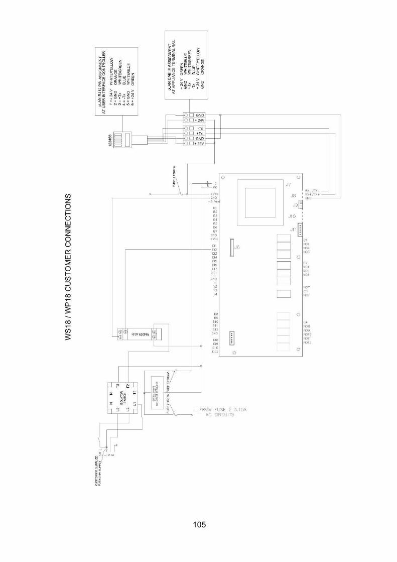
105

106
. Manual is accurate at the date of printing (E&OE) but will be superseded and should be disregarded if specifications and/or appearances are changed in the interests of continued product improvement
CODE 4341 ISSUE 6
DEC 2017


![42. Software Ecosystems - TU Dresdenst.inf.tu-dresden.de/files/teaching/ws18/saab/... · [Cusumano] Michael A. Cusumano. Staying Power: Six Enduring Principles for Managing Strategy](https://img.pdfslide.us/doc/110x75/5f7b6999c906da4ee9565f6b/42-software-ecosystems-tu-cusumano-michael-a-cusumano-staying-power-six.jpg)


![H2020 Programme - ec.europa.euec.europa.eu/research/participants/data/ref/h2020/call_ptef/pt/... · 2 [Proposal Acronym] template WP18-20 v20171107 • What are the expected outcomes](https://img.pdfslide.us/doc/110x75/5a83cace7f8b9a9d308f0bdb/h2020-programme-ec-proposal-acronym-template-wp18-20-v20171107-what-are.jpg)