Embed Size (px)
Citation preview
~-4$ EN
! FROI05409. ..+.. .“+_____________
WOBBE INDEX CONTROL SYSTEM IN GAS INDUSTRY PROCESSES
SYSTEME DE CONTROLE DE L’INDEX DE WOBBE DU GAZNATUREL DANS LES PROCESSUS INDUSTRIALS
M. Cassibbaand M. BertaniSNAM, ltaly
ABSTRACT
Natural gassupplied toindustry forprocess utilisations originates from different sources and that cancause fluctuations in gas composition. Changing gas composition may lead to production problems inindustry with sensitive thermal processes (particularly glass industry and thermal metal treatments),such as efficiency and product quality. An equipment suitable to control and adjust such variations hasbeen developed. Experimental tests in laboratory were carried out in order to investigate the controlsystem accuracy and reliability. In particular five different settings were tested: at a preset thermal inputby adjusting the natural gas flow rate in respect to Wobbe Index variations; at a set furnacetemperature and stack oxygen level with variable thermal input by monitoring the Wobbe Index value;at constant Wobbe Index value by adding air to natural gas; at constant thermal input and prefixedWobbe Index value by adding air to natural gas and varying the air and gas mixture flow rate; grosscalorific value control by adding air or LPG to natural gas. All the tested settings gave good results.This report illustrates these results and the main features of the control system. The control andregulation system was installed in two glass factories for field tests.
RESUME
Le gaz naturel utilise clans [es processus industrials provient de gisements a caracteristiquesdifferences qui peuvent dormer lieu a des fluctuations clans la composition du gaz. Ces variationspeuvent entralner des problemes clans certaines processus industrials tels que, en particulier, ceux duverre et du traitement des metaux. Pour resoudre ces problemes on a developpe un systeme decontr61e en mesure de regler Ies variations de la qualite du gaz et des essais experimentaux ont eteeffectues en Iaboratoire pour en determiner la precision et la fiabilite. En particulier, on a experimentcinq configurations differences de reglage : maintien d’une valeur constante du debit thermique par Iereglage du debit du gaz, en fonction de la variation de I’index de Wobbe ; maintien de valeurs prefixeesde la temperature du four et de la concentration d’oxygene clans Ies fumees en fonction de la variationdu debit thermique et de I’index de Wobbe ; maintien d’une valeur basse et constante de I’index deWobbe par I’addition d’air au debit du gaz ; maintien d’une valeur constante du debit thermique, a unevaleur de I’index de Wobbe predetermine, par I’addition d’air au debit du gaz et simultanementreglage du debit du melange air/gaz ; maintien d’une valeur constante du pouvoir calorifique parI’addition d’air ou de gaz propane Iiquide au debit du gaz. Toutes Ies configurations testees ont donned’excellents resultats. Ce memoire illustre Ies resultats de I’experimentation et Ies caracteristiquesprincipals du systeme de contr61e. Le systeme de contr61e et reglage a ete installe clans deuxindustries du verre pour essai.
DISCLAIMER
Portions of this document may be illegiblein electronic imageproduced from thedocument.
products. Images arebest avaiiable original
I
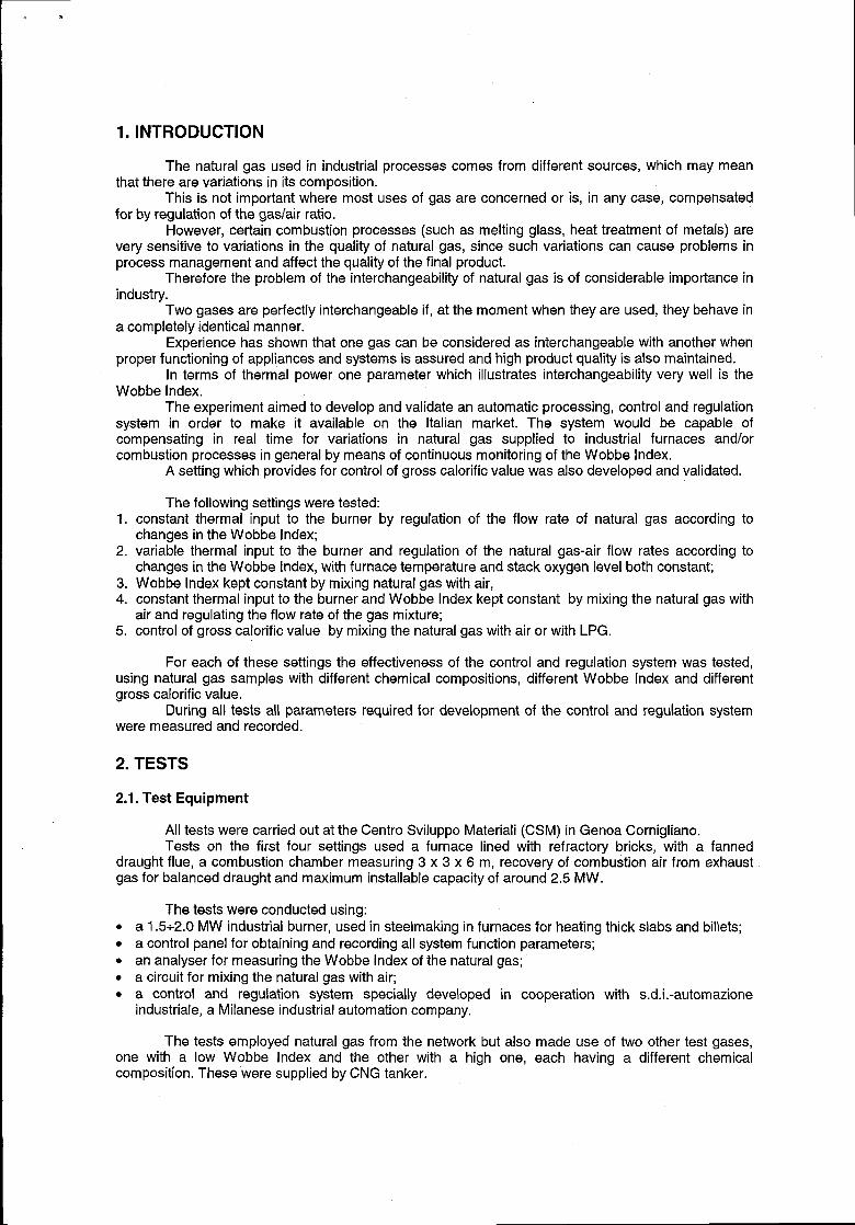
1. INTRODUCTION
The natural gas used in industrial processes comes from different sources, which may meanthat there are variations in its composition.
This is not important where most uses of gas are concerned or is, in any case, compensatedfor by regulation of the gas/air ratio.
However, certain combustion processes (such as melting glass, heat treatment of metals) arevery sensitive to variations in the quality of natural gas, since such variations can cause problems inprocess management and affect the quality of the final product.
Therefore the problem of the interchangeability of natural gas is of considerable importance inindustry.
Two gases are perfectly interchangeable if, at the moment when they are used, they behave ina completely identical manner.
Experience has shown that one gas can be considered as interchangeable with another whenproper functioning of appliances and systems is assured and high product quality is also maintained.
In terms of thermal power one parameter which illustrates interchangeability very well is theWobbe Index.
The experiment aimed to develop and validate an automatic processing, control and regulationsystem in order to make it available on the Italian market. The system would be capable ofcompensating in real time for variations in natural gas supplied to industrial furnaces and/orcombustion processes in general by means of continuous monitoring of the Wobbe Index.
A setting which provides for control of gross calorific value was also developed and validated.
The following settings were tested:1. constant thermal input to the burner by regulation of the flow rate of natural gas according to
changes in the Wobbe Index;2. variable thermal input to the burner and regulation of the natural gas-air flow rates according to
changes in the W obbe Index, with furnace temperature and stack oxygen level both constant3. Wobbe Index kept constant by mixing natural gas with air,4. constant thermal input to the burner and Wobbe Index kept constant by mixing the natural gas with
air and regulating the flow rate of the gas mixture;5. control of gross calorific value by mixing the natural gas with air or with LPG.
For each of these settings the effectiveness of the control and regulation system was tested,using natural gas samples with different chemical compositions, different Wobbe Index and differentgross calorific value.
During all tests all parameters required for development of the control and regulation systemwere measured and recorded.
2. TESTS
2.1. Test Equipment
All tests were carried out at the Centro Sviluppo Materiali (CSM) in Genoa Cornigliano.Tests on the first four settings used a furnace lined with refractory bricks, with a fanned
draught flue, a combustion chamber measuring 3 x 3 x 6 m, recovery of combustion air from exhaustgas for balanced draught and maximum installable capacity of around 2.5 MW.
The tests were conducted using:. a 1.5+2.0 MW industrial burner, used in steelmaking in furnaces for heating thick slabs and billets;● a control panel for obtaining and recording all system function parameters;. an analyser for measuring the Wobbe index of the natural gas;● a circuit for mixing the natural gas with air;● a control and regulation system specially developed in cooperation with s.d.i .-automazione
industrial, a Milanese industrial automation company.
The tests employed natural gas from the network but also made use of two other test gases,one with a low Wobbe Index and the other with a high one, each having a different chemicalcomposition. These were supplied by CNG tanker.
.
The air used for mixing with natural gas was purified and dried to remove any oil and/ormoisture using a suitable filter system.
The air pipe inlet into the natural gas pipe was made at a sufficient distance from the WobbeIndex measurement device to ensure that mixing was complete.
During the tests all parameters needed for development of the control and regulation systemwere measured and recorded (furnace temperature, natural gas flow rate, combustion air flow rate,mixer air flow rate, stack oxygen level, Wobbe Index).
The fifth setting was tested using a furnace for testing burners up to 500 kW, with walls ofrefractory brick, a controlled draught flue, a combustion chamber measuring 1 x 1.2 x 2.2 m andcooling pipes to reduce the heat input.
The tests for this setting were conducted using:● an industrial burner of the type used in steelmaking of around 500 kW;● a control panel for obtaining and recording all system function parameters;. an analyser for measuring the gross calorific value of the natural gas;● a gas cromatograph;. a control and regulation system specially developed in cooperation with s.d.i.-automazione
industrial, a Milanese industrial automation company,● a circuit for mixing the natural gas with air or LPG as required.
The tests employed natural gas from the network but also made use of two other test gases,one with a low gross calorific value and the other with a high one, each having a different chemicalcomposition. These were supplied by CNG tanker.
The air used for mixing with the natural gas, from the CSM internal compressed air line, waspurified and dried to remove any oil and/or moisture using a suitable filter system.
The LPG used was supplied in bottles. This was commercial propane - a mixture of 88%propane with 127. butane.
2.2. Measurement of the Wobbe Index
The heat output of a burner is proportional to the calorific value of the gas per unit of volumeand to the gas flow rate to the burner, which is inversely proportional to the square root of its density.
The Wobbe Index (higher) is defined by the following ratio:
WI.?r
where:
WI = Wobbe IndexGCV = gross calorific valuedr = relative density of the gas compared with air
Therefore the Wobbe Index is expressed by the same unit of measurement of the calorificvalue that is in MJ per unit of volume.
This means that two gases which have the same Wobbe Index give the same heat output tothe burner, for the same supply pressure.
A Wobbe Index meter was used to measure continuously the Wobbe Index.The principle on which the meter works is briefly described below.Inside the instrument a fixed quantity of gas, taken in continually, is burnt under prefixed
conditions of air excess. A zircon dioxide cell measures the percentage of residual oxygen in theexhaust gas from combustion. As there is a linear ratio between the percentage of residual oxygen andthe Wobbe Index and this ratio is set in the instrument when it is calibrated, the value of the WobbeIndex is automatically determined by measuring the percentage of oxygen.
The main technical specifications of the Wobbe Index meter used are:
●
●
●
●
range of measurement 40+55 MJ/Sm3precision + 0.4% Of the measured value
repeatability t ().1“A of the measured vaiue
response time c 8 sees (90Y0 of the measured Vi3k.E)
A pump is inserted between the gas intake point and the Wobbe Index meter in order tomaintain the pressure at the entrance to the measuring device at 3 bar.
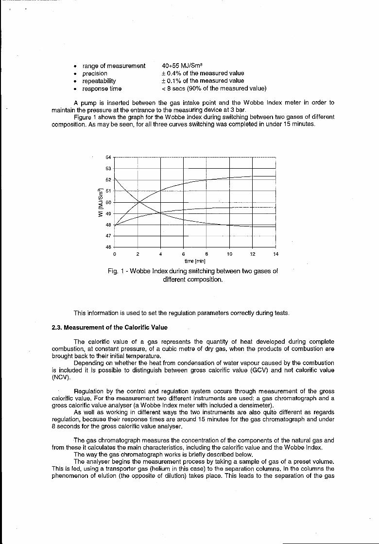
Figure 1 shows the graph for the Wobbe Index during switching between two gases of differentcomposition. As maybe seen, for all three curves switching was completed in under 15 minutes.
54- ,
53
52-
‘~ 5’
350- —~ j~ 49
48\
47 ,
46 Io 2 4 6 6 10 12 14
time[m”n]
Fig. 1- Wobbe Index during switching between two gases of
different composition.
This information is used to set the regulation parameters correctly during tests.
2.3. Measurement of the Calorific Value
The calorific value of a gas represents the quantity of heat developed during completecombustion, at constant pressure, of a cubic metre of dry gas, when the products of combustion arebrought back to their initial temperature.
Depending on whether the heat from condensation of water vapour caused by the combustionis included it is possible to distinguish between gross calorific value (GCV) and net calorific value(NW).
Regulation by the control and regulation system occurs through measurement of the grosscalorific value. For the measurement two different instruments are used: a gas chromatography and agross calorific value analyser (a Wobbe Index meter with included a densimeter).
As well as working in different ways the two instruments are also quite different as regardsregulation, because their response times are around 15 minutes for the gas chromatography and under8 seconds for the gross calorific value analyser.
The gas chromatography measures the concentration of the components of the natural gas andfrom these it calculates the main characteristics, including the calorific value and the Wobbe Index.
The way the gas chromatography works is briefly described below.The analyser begins the measurement process by taking a sample of gas of a preset volume.
This is led, using a transporter gas (helium in this case) to the separation columns. In the columns thephenomenon of elution (the opposite of dilution) takes place. This leads to the separation of the gas
.
into its components: as the molecules move along the columns at different speeds due to their differentmolecular weights they come to the end of the columns at different times. By measuring the thermalconductivity the instrument can identify the component and its concentration.
The gross calorific value analyser calculates the calorific value of the natural gas by means ofthe ratio:
~1 = GCV
&
where:
WI = Wobbe IndexGCV = Gross Calorific Valued, = relative density of the gas compared with air
measuring the Wobbe Index and at the same time measuring the density of the gas using a densitysensor.
A pump is inserted between the gas intake point and the meter in order to maintain thepressure at the-entrance to the measuring device at 3 bar.
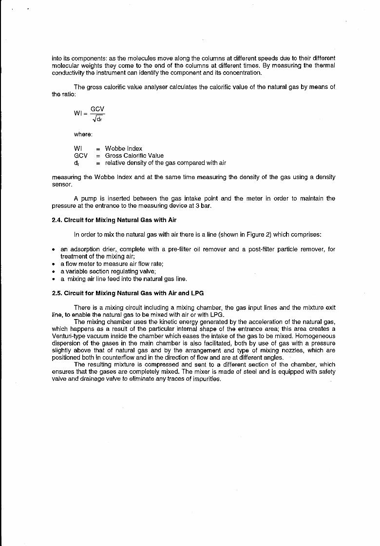
2.4. Circuit for Mixing Natural Gas with Air
In order to mix the natural gas with air there is a line (shown in Figure 2) which comprises:
● an adsorption drier,, complete with a pre-filter oil remover and a post-filter particIe remover,treatment of the mixing air;
s a flow meter to measure air flow rate;● a variable section regulating valve;● a mixing air line feed into the natural gas line.
2.5. Circuit for Mixing Natural Gas with Air and LPG
for
There is a mixing circuit including a mixing chamber, the gas input lines and the mixture exitline, to enable the natural gas to be mixed with air or with LPG.
The mixing chamber uses the kinetic energy generated by the acceleration of the natural gas,which happens as a result of the particular internal shape of the entrance area; this area creates aVenturi-type vacuum inside the chamber which eases the intake of the gas to be mixed. Homogeneousdispersion of the gases in the main chamber is also facilitated, both by use of gas with a pressureslightly above that of natural gas and by the arrangement and type of mixing nozzles, which arepositioned both in counterflow and in the direction of flow and are at different angles.
The resulting mixture is compressed and sent to a different section of the chamber, whichensures that the gases are completely mixed. The mixer is made of steel and is equipped with safetyvalve and drainage valve to eliminate any traces of impurities.
. .
FUELGASSUPPLY to burner
dAIR SUPPLY
control fromregulator
Fig. 2- Mixing air line.
The gas input lines are fitted with non-return valves and temperature and pressure gauges.Each line is also equipped with an equal percentage control valve which is normally closed, completewith pneumatic servocontrol and electropneumatic positioner (signal 4-+20 mA).
The mixture exit line is also fitted with temperature and pressure gauges.
2.6. Regulation Equipment
The equipment used performs several functions: it calculates the correct gas flow rate, itcompensates for variations in the quality of the natural gas and, if required, it also regulates acharacteristic process variable and/or a second variable correlated with it.
The system is designed particularly to:● calculate the flow rate using the entrances of differential pressure, relative pressure and line
temperature;● manage the automatic regulation of the process related to the five settings;● manage the interface with the operator by means of keyboard and display on the machine, allowing
the equipment to be programmed, the variables concerned to be seen, operational status, local setpoints and regulator parameters to be altered;
● manage the interface with the operator by means of a PC connected to the system, by means ofwhich graphical screens and control panels allow regulation parameters, set points” and/or exitvalues to be altered;
● manage the settings of the equipment (entrances, regulation exit, feed, regulation card etc.).
3. TESTS AND TEST RESULTS
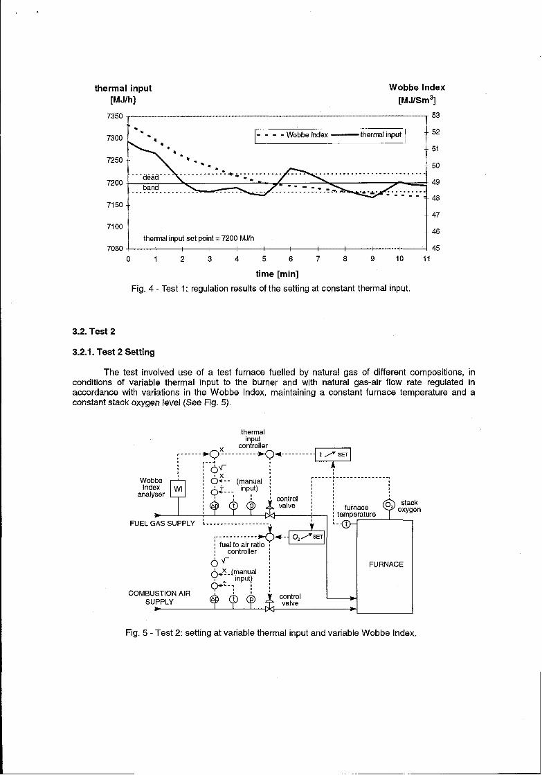
3.1. Test 1
3.1.1. Test 1 Setting
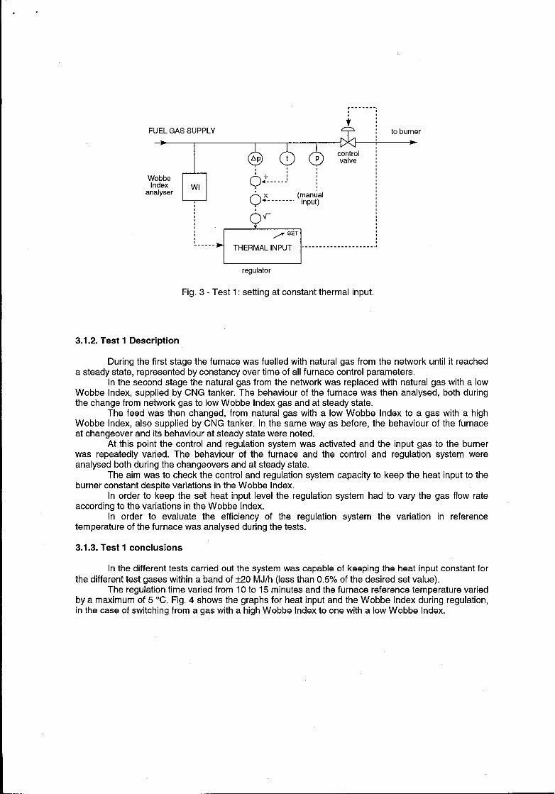
The test involved use of a test furnace fuelled by natural gas of different compositions, inconditions of constant thermal input to the burner and with natural gas flow rate regulated inaccordance with variations in the Wobbe Index (See Fig. 3).
.,
,.-.---
FUEL GAS SUPPLY 4
Wb&.WI
analyser ‘xQ“ ‘-------” ‘lyuY;’,
‘Av-
,/ SET
-. .-. .THERMAL INPUT . . . . . . . . . . . . . . . . . . . .
to burner
>
regulator
Fig. 3- Test 1: setting at constant thermal input.
3.1.2. Test 1 Description
During the first stage the furnace was fuelled with natural gas from the network until it reacheda steady state, “represented by constancy over time of all furnace control parameters.
In the second stage the natural gas from the network was replaced with natural gas with a lowWobbe Index, supplied by CNG tanker. The behaviour of the furnace was then analysed, both duringthe change from network gas to low Wobbe Index gas and at steady state.
The feed was then changed, from natural gas with a low Wobbe Index to a gas with a highWobbe Index, also supplied by CNG tanker. In the same way as before, the behaviour of the furnaceat changeover and its behaviour at steady state were noted.
At this point the control and regulation system was activated and the input gas to the burnerwas repeatedly varied. The behaviour of the furnace and the control and regulation system wereanalysed both during the changeovers and at steady state.
The aim was to check the control and regulation system capacity to keep the heat input to theburner constant despite variations in the Wobbe Index.
In order to keep the set heat input level the regulation system had to vary the gas flow rateaccording to the variations in the Wobbe Index.
In order to evaluate the efficiency of the regulation system the variation in referencetemperature of the furnace was analysed during the tests.
3.1.3. Test 1 conclusions
In the different tests carried out the system was capable of keeping the heat input constant forthe different test gases within a band of *2O MJ/h (less than 0.5’% of the desired set value).
The regulation time varied from 10 to 15 minutes and the furnace reference temperature variedby a maximum of 5 “C. Fig. 4 shows the graphs for heat input and the Wobbe Index during regulation,in the case of switching from a gas with a high Wobbe Index to one with a low Wobbe Index.
—
thermal input Wobbe Index
[MJlh] [MJ/Sm3]
7350 I ~ 53
●☛
7250
. . . . . . . . . . . . . . . . . . . . . . . . . . . .
7200band
7150-
-47
7100-
thermal input set point = 7200 M.I/h
7050
0 1 2 3 4 5 6 7 8 9 10 11
time [rein]
Fig. 4- Test 1: regulation results of the setting at constant thermal input.
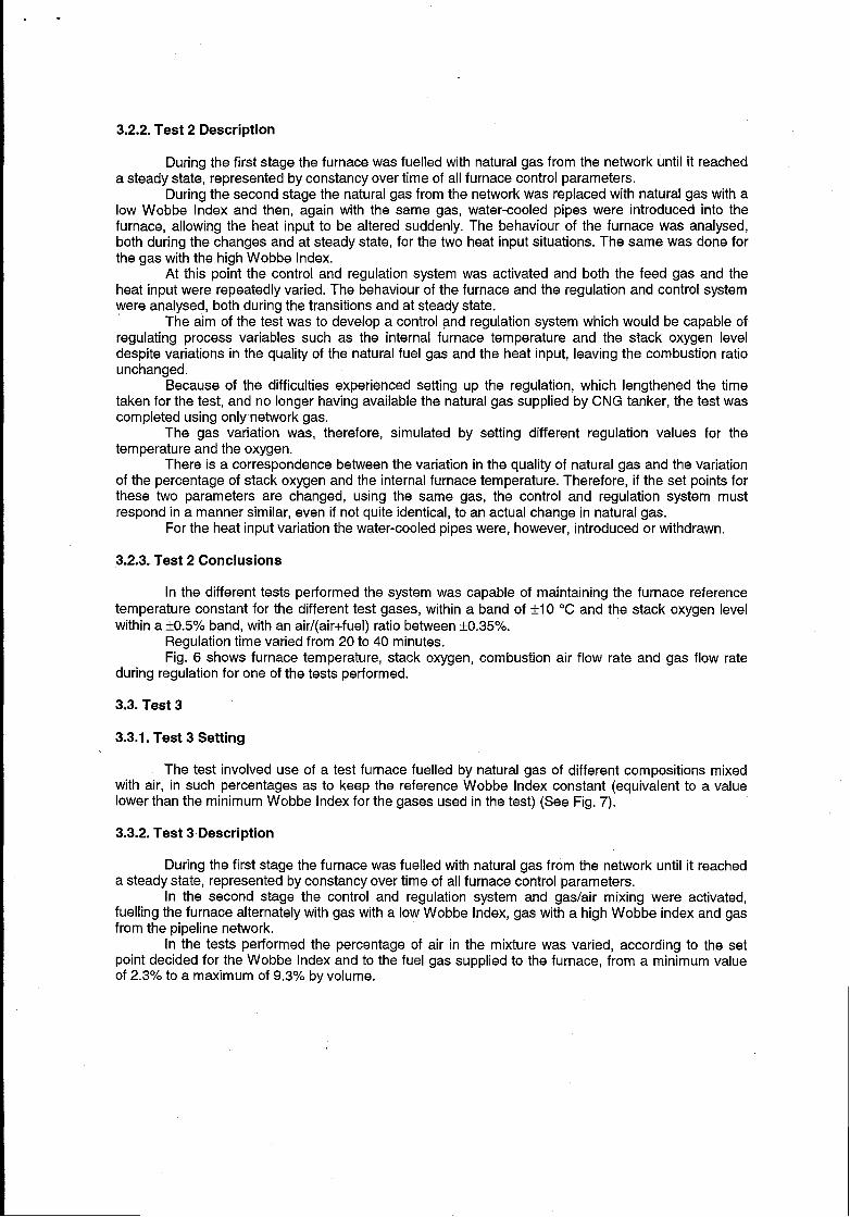
3.2. Test 2
3.2.1. Test 2 Setting
The test involved use of a test furnace fuelled by natural gas of different compositions, inconditions of variable thermal input to the burner and with natural gas-air flow rate regulated inaccordance with variations in the Wobbe Index, maintaining a constant furnace temperature and aconstant stack oxygen level (See Fig. 5).
, -----, ----- . . --...---,,,,,II
analyser ,,
* : temperatureFUEL GAS SUPPLY : ------------------,
:iii;iiiz+++‘-o
controller Iov-
FURNACE
COMBUSTION AIRSUPPLY
Fig. 5- Test 2: setting at variable thermal input and variable Wobbe Index.
.
3.2.2. Test 2 Description
During the first stage the furnace was fuelled with natural gas from the network until it reacheda steady state, represented by constancy over time of all furnace control parameters.
During the second stage the natural gas from the network was replaced with natural gas with a
low Wobbe Index and then, again with the same gas, water-cooled pipes were introduced into the
furnace, allowing the heat input to be altered suddenly. The behaviour of the furnace was analysed,both during the changes and at steady state, for the two heat input situations. The same was done for
the gas with the high Wobbe Index.
At this point the control and regulation system was activated and both the feed gas and the
heat input were repeatedly varied. The behaviour of the furnace and the regulation and control systemwere analysed, both during the transitions and at steady state.
The aim of the test was to develop a control and regulation system which would be capable ofregulating process variables such as the internal furnace temperature and the stack oxygen leveldespite variations in the quality of the natural fuel gas and the heat input, leaving the combustion ratiounchanged.
Because of the difficulties experienced setting up the regulation, which lengthened the timetaken for the test, and no longer having available the natural gas supplied by CNG tanker, the test wascompleted using only network gas.
The gas variation was, therefore, simulated by setting different regulation values for thetemperature and the oxygen.
There is a correspondence between the variation in the quality of natural gas and the variationof the percentage of stack oxygen and the internal furnace temperature. Therefore, if the set points forthese two parameters are changed, using the same gas, the control and regulation system mustrespond in a manner similar, even if not quite identical, to an actual change in natural gas.
For the heat input variation the water-cooled pipes were, however, introduced or withdrawn.
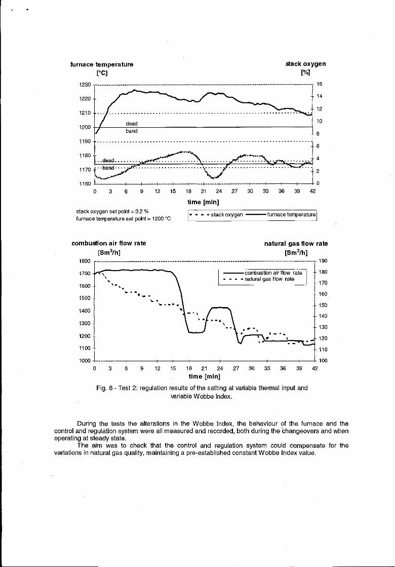
3.2.3. Test 2 Conclusions
In the different tests performed the system was capable of maintaining the furnace referencetemperature constant for the different test gases, within a band of +1O “C and the stack oxygen levelwithin a ~0.5’Yo band, with an air/( air+fueI) ratio between ~0.35°Y&
Regulation time varied from 20 to 40 minutes.Fig. 6 shows furnace temperature, stack oxygen, combustion air flow rate and gas flow rate
during regulation for one of the tests performed.
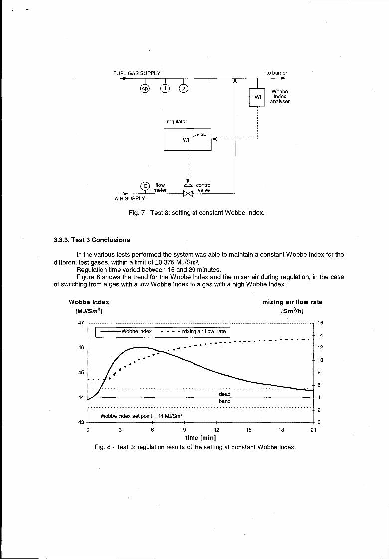
3.3. Test 3
3.3.1. Test 3 Setting
The test involved use of a test furnace fuelled by natural gas of different compositions mixedwith air, in such percentages as to keep the reference Wobbe Index constant (equivalent to a valuelower than the minimum Wobbe Index for the gases used in the test) (See Fig. 7).
3.3.2. Test 3Description
During the first stage the furnace was fuelled with natural gas from the network until it reacheda steady state, represented by constancy over time of all furnace control parameters.
In the second stage the control and regulation system and gas/air mixing were activated,fuelling the furnace alternately with gas with a low Wobbe Index, gas with a high Wobbe index and gasfrom the pipeline network.
In the tests performed the percentage of air in the mixture was varied, according to the setpoint decided for the Wobbe Index and to the fuel gas supplied to the furnace, from a minimum valueof 2,3% to a maximum of g.syo by volume.
.-
furnace temperature stack oxygen
1230
1220
1210
1200
1190
1180
1170
1160
PC] po]1 i 16
-14
-12
-10
f band-8
. . . . . . . . . . . . . . . . . . . . . . . . . . . . . . . . . . . . . . . . . . . . . . . . . . . . . . . . . . . . . . . . . . . . . . . . .6
...u.--m\
..dead . . . . . . . ..~~~Vwe~’~----------- 4. . . . . . . . .
-- ba~~.~~>!’r~ . . . . . . . . . . . . . . . . . . . . . ~ w. . . . . . . . . . . . . . . . . . . . . . . . . . . . -#. -.
J%J”J-2
0 3 6 9 12 15 18 21 24 27 30 33 36 39 42
time [rein]
stack oxygen set point = 3.2 Y.
furnace terrperature set point= 1200 “C ‘“- - stack oxygen — f urnace temperature
combustion air flow rate natural gas flow rate
[Sm3/h] [Sm3/h]
1800I
190
1500- -
1400- -
1300- -
1200-
1100
w.-+ -- \
150
140
130
120
J- 110
—H—t++J 1001000 ~
O 3 6 9 12 15 18 21 24 27 30 33 36 39 42
time [rein]
Fig. 6- Test 2: regulation results of the setting at variable thermal input and
variable Wobbe Index.
During the tests the alterations in the Wobbe index, the behaviour of the furnace and thecontrol and regulation system were all measured and recorded, both during the changeovers and whenoperating at steady state.
The aim was to check that the control and regulation system could compensate for thevariations in natural gas quality, maintaining a pre-established constant Wobbe Index value.
FUEL GAS SUPPLY to burner
.-
A>
y.llc:l
analyserI -I
regulator I~------- ‘-------1
I
flow controlmeter valve
AIR SUPPLY
Fig. 7- Test 3: setting at constant Wobbe Index.
3.3.3. Test 3 Conclusions
In the various tests performed the system was able to maintain a constant Wobbe Index for thedifferent test gases, within a limit of +0.375 MJ/Sm3.
Regulation time varied between 15 and 20 minutes.Figure 8 shows the trend for the Wobbe Index and the mixer air during regulation, in the case
of switching from a gas with a low Wobbe Index to a gas with a high Wobbe Index.
Wobbe Index mixing air flow rate
[MJ/Sm3] [Sm3/h]
47
46
45
44
I III — Wobbe Index - - - - tixing air f low rate I I
I I------- -.,------ ---””
t
dead
band
16
14
12
10
8
6
4
t. . . . . . . . . . . . . . . . . . . . . . . . . . . . . . . . . . . . . . . . . . . . . . . . . . . . . . . . . . . . . . . . . . . . . . . . . . . . .
i2\ WobbeIndexset point= 44 fvUISrF I
0 3 6 9 12 15 18 21
time [rein]
Fig. 8- Test 3: regulation results of the setting at constant Wobbe Index.
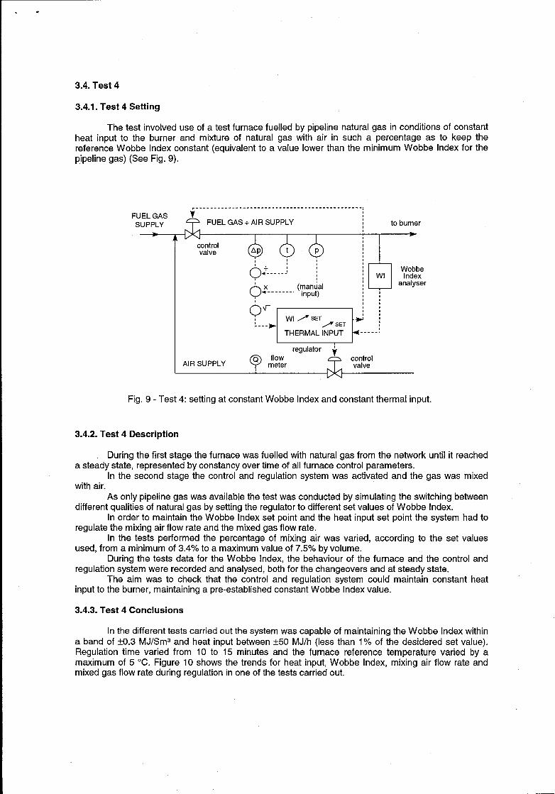
3.4. Test 4
3.4.1. Test 4 Setting
.-
The test involved use of a test furnace fuelled by pipeline natural gas in conditions of constantheat input to the burner and mixture of natural gas with air in such a percentage as to keep thereference Wobbe Index constant (equivalent to a value lower than the minimum Wobbe Index for thepipeline gas) (See Fig. 9).
---------- ------------ . . . . . . . . . . . . . . . . . . . . . . . . .,FUEL GASSUPPLY ~ FUEL GAS+ AIR SUPPLY to burner
~:.~ [
‘xQ
(manual‘-------” input)
10W#&W[
analyser,,,,,,
‘:”E=Hregulator ~
QQ flowAIR SUPPLY meter .7 ‘W:’
Fig. 9- Test 4: setting at constant Wobbe Index and constant thermal input.
3.4.2. Test 4 Description
During the first stage the furnace was fuelled with natural gas from the network until it reacheda steady state, represented by constancy over time of all furnace control parameters.
In the second stage the control and regulation system was activated and the gas was mixedwith air.
As only pipeline gas was available the test was conducted by simulating the switching betweendifferent qualities of natural gas by setting the regulator to different set values of Wobbe Index.
In order to maintain the Wobbe Index set point and the heat input set point the system had toregulate the mixing air flow rate and the mixed gas flow rate.
In the tests performed the percentage of mixing air was varied, according to the set valuesused, frOm a minimUm Of 3.4% tO a Wtaxh-irn VdUe Of 7’.!Y2o by VOkJme.
During the tests data for the Wobbe Index, the behaviour of the furnace and the control andregulation system were recorded and analysed, both for the changeovers and at steady state.
The aim was to check that the control and regulation system could maintain constant heatinput to the burner, maintaining a pre-established constant Wobbe Index value.
3.4.3. Test 4 Conclusions
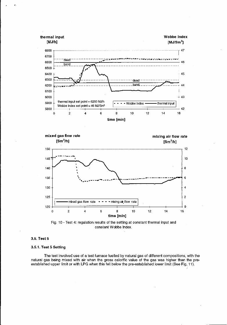
In the different tests carried out the system was capable of maintaining the Wobbe Index withina band of ~0.3 MJ/Sms and heat input between f50 MJ/h (less than 17. of the desidered set value).Regulation time varied from 10 to 15 minutes and the furnace reference temperature varied by amaximum of 5 ‘C. Figure 10 shows the trends for heat input, Wobbe Index, mixing air flow rate andmixed gas flow rate during regulation in one of the tests carried out.
“t-
hermal input Wobbe Index
[MJ/h] [MJ/Sm3]
6700- -dead
. . . . . . . . . . . . . . . . . . . . . . . . . . . . . . ..iwtir --- =-s -0- .,---- .-*-*-.-,-.% ..*-* :.W!. . . . .
6600-●*
band ●
n
. . . . . . . . . . . . . . . . . . . . . . . . . . . . . . . . . . . . . . . . . . . . . . . . . . . . . . . . . . . . . . . . . . . . . . .6500- - .
● 8~
6400
6300
6200
6100
6000
5900
5800
●
✎✎✎✎✎✎✎✎✎✎✎✎ ..&a& . . . . . . . . . . . . . . . . . . . . . .
%-
-.-. -.-tia.>*~*--------------- ------
thermal input set point = 6250 M.I/h . - . - ~obbe ,ndex
Wobbe Index set point= 46 hAJ/SrIP— thermal input
47
46
45
44
43
42
0 2 4 6 8 10 12 14 16
time [rein]
mixed gas flow rate mixing air flow rate[Sm3/h] [Sm3/h]
.-.1w
145
140
135
130
125
*. --------
“v’=%t){ ,-**-. .e ------- “
.--- =_*-- . . . . . . ..- . . . . . .
.
II — nixed gas flow rate - - - - nixing ai[ flow rate [
120 1 ‘I
12
10
8
6
[
4
2
00 2 4
Fig. 10- Test 4: regulation
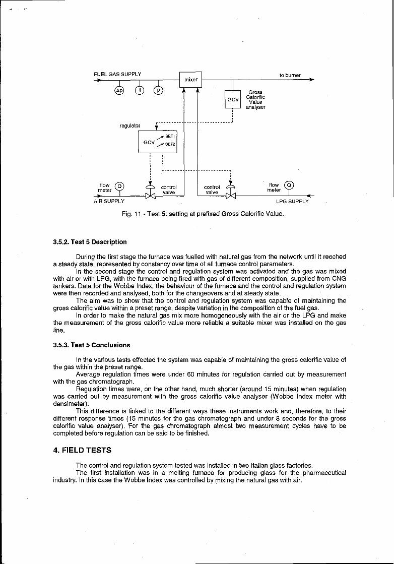
3.5. Test 5
3.5.1. Test 5 Setting
6 8 10 12 14 16
time [rein]
results of the setting at constant thermal input andconstant Wobbe Index.
The test involved use of a test furnace fuelled by natural gas of different compositions, with thenatural gas being mixed with air when the gross calorific value of the gas was higher than the pre-established upper limit or with LPG when this fell below the pre-established lower limit (See Fig. 11).
4!r-
FUEL GAS SUPPLY to burner*
Gross~~” C;:;c
analyser,
,. . . . . . . . . . . . J
regulator ‘ ---------- -----
c1
/ SET’Gcv > SET2
,,,,,,,,II
!------- . ----- ------------ .,u~
AIR SUPPLY LPG SUPPLY
Fig. 11- Test 5: setting at prefixed Gross Calorific Value.
3.5.2. Test 5 Description
During the first stage the furnace was fuelled with natural gas from the network until it reacheda steady state, represented by constancy over time of all furnace control parameters.
In the second stage the control and regulation system was activated and the gas was mixedwith air or with LPG, with the furnace being fired with gas of different composition, supplied from CNG
tankers. Data for the Wobbe Index, the behaviour of the furnace and the control and regulation system
were then recorded and analysed, both for the changeovers and at steady state.
The aim was to show that the control and regulation system was capable of maintaining the
gross calorific value within a preset range, despite variation in the composition of the fuel gas.In order to make the natural gas mix more homogeneously with the air or the LPG and make
the measurement of the gross calorific value more reliable a suitable mixer was installed on the gasline.
3.5.3. Test 5 Conclusions
In the various tests effected the system was capable of maintaining the gross calorific value ofthe gas within the preset range.
Average regulation times were under 60 minutes for regulation carried out by measurementwith the gas chromatography.
Regulation times were, on the other hand, much shorter (around 15 minutes) when regulationwas carried out by measurement with the gross calorific value analyser (Wobbe Index meter withdensimeter).
This difference is linked to the different ways these instruments work and, therefore, to theirdifferent response times (15 minutes for the gas chromatography and under 8 seconds for the grosscalorific value analyser). For the gas chromatography almost two measurement cycles have to becompleted before regulation can be said to be finished.
4. FIELD TESTS
The control and regulation system tested was installed in two Italian glass factories.The first installation was in a melting furnace for producing glass for the pharmaceutical
industry. In this case the Wobbe Index was controlled by mixing the natural gas with air.
*..-
The system manages to keep the preset Wobbe Index constant within a +0.3 MJ/Sm3 band,with a regulation time of under 10 minutes. Variations in the operating temperature of the furnace arelimited to around 3-4 ‘C, without the system these variations are over 10 ‘C. Furthermore, the qualityof the finished product is unchanged.
The second installation was carried out on a float furnace for production of flat glass. In thiscase the gross calorific value of the fuel gas was controlled by mixing it with air or with LPG, using agas chromatography to measure the calorific value.
The system is capable of compensating for variations in the gross calorific value ranging from38 to 41 MJ/Sm’, bringing them within a range of variability determined by presetting a lower set pointand an upper set point, with a dead band of ~0.2 MJ/Sm’ variation. Average regulation times arearound 30+45 minutes.
5. CONCLUSIONS
The control and regulation system tested gave results which were more than satisfactory for allfive test settings.
The choice of setting best adapted to the user’s needs must be made on an individual basis,depending on the process which the system is to be used for and the parameters which the userdecides to keep under control.
In general it maybe said, however, that setting 1 is more suitable for single uses with constantheat input, setling 2 for single uses with processes where heat input is variable, setting 3 in caseswhere a number of uses require constant gas quality, setting 4 for a number of uses where constantgas quality and constant heat input are required. Setting 5 is suitable for use where the most importantfactor is to keep the calorific value of the natural gas within a certain range, since fluctuations incalorific value which fall outside the optimum value for the process may cause system managementand capacity problems, as well as problems with the quality of the finished product.
Settings 3 and 5 have been successfully used in two Italian glass factories.