Embed Size (px)
Citation preview

C316 ORP Controller with pH Display, 24 Volt
OW
NE
R’S
M
AN
UA
L

Table of ContentsI. Introduction . . . . . . . . . . . . . . . . . . . . . . . . . . . . . . . . .2
II. Specifications . . . . . . . . . . . . . . . . . . . . . . . . . . . . . . .3
III. Components . . . . . . . . . . . . . . . . . . . . . . . . . . . . . . . .3
IV. Pre-installation . . . . . . . . . . . . . . . . . . . . . . . . . . . . . .4
A. Timed Feeds . . . . . . . . . . . . . . . . . . . . . . . . . . . . .4
B. Switch Settings . . . . . . . . . . . . . . . . . . . . . . . . . . .5
V. Installation . . . . . . . . . . . . . . . . . . . . . . . . . . . . . . . . .6
A. Feeding Systems . . . . . . . . . . . . . . . . . . . . . . . . . .6
B. Controller Installation . . . . . . . . . . . . . . . . . . . . . . .6
C. Flow Cell Installation . . . . . . . . . . . . . . . . . . . . . . .7
D. Sensor Installation . . . . . . . . . . . . . . . . . . . . . . . .11
E. Electrical . . . . . . . . . . . . . . . . . . . . . . . . . . . . . . .11
F. Start-up Operations . . . . . . . . . . . . . . . . . . . . . . .11
G. Sanitizer Settings . . . . . . . . . . . . . . . . . . . . . . . . .12
H. pH Calibration . . . . . . . . . . . . . . . . . . . . . . . . . . .13
VI. Panel Features . . . . . . . . . . . . . . . . . . . . . . . . . . . . .14
VII. Operation . . . . . . . . . . . . . . . . . . . . . . . . . . . . . . . . .15
A. Setting Feed and Delay Times . . . . . . . . . . . . . . .15
B. Feed Light Activation . . . . . . . . . . . . . . . . . . . . . .15
C. Out-of-range Indicator . . . . . . . . . . . . . . . . . . . . .16
D. Manual Feed . . . . . . . . . . . . . . . . . . . . . . . . . . . .16
E. Winterizing . . . . . . . . . . . . . . . . . . . . . . . . . . . . .16
VIII. Maintenance . . . . . . . . . . . . . . . . . . . . . . . . . . . . . . .17
A. Testing . . . . . . . . . . . . . . . . . . . . . . . . . . . . . . . .17
B. Cleaning the Sensor Tips . . . . . . . . . . . . . . . . . . .17
C. Checking the ORP Sensor . . . . . . . . . . . . . . . . . .18
D. Checking the pH Sensor . . . . . . . . . . . . . . . . . . .18
IX. Erosion Feeder Operating Tips . . . . . . . . . . . . . . . . .19
X. Troubleshooting . . . . . . . . . . . . . . . . . . . . . . . . . . . . .21
XI. Guidelines for Using ORP for Water Maintenance . . .22
XII. Warranty . . . . . . . . . . . . . . . . . . . . . . . . . . . . . . . . . .24

POWER
ON
OFF
MAINTAINPROPER pH
FEED
MANUAL
pH
ADJ.FEED
C-316 ORP Controller w/pH Display, 24 V
6.6
6.8
7.0
7.27.4 7.6
7.8
8.08.2
8.4
¥20
0¥3
00
¥400 ¥500 ¥600 ¥700 ¥800¥900
¥1000
¥10
0
DEC
REASE ¥INCREASE
OR
P
pH
2
I. IntroductionFor your protection, read all instructions carefully beforeinstalling or operating this automatic controller.
The Polaris Watermatic® C316 24-Volt Controller is designed toautomatically monitor and maintain the sanitizer level and pHbalance in swimming pools, spas and any circulating water sys-tem that requires water chemistry management. This controlleris designed for easy installation and simple operation, and isused with tablet erosion feeders.
During the filtration cycle of the pool or spa, the sanitizer leveland pH balance are maintained by a constant measurement ofthe ORP (Oxidation-Reduction-Potential) and pH balance of the water. Levels are displayed on the controller’s ORP and pHlight bar arrays (see Figure 1). If the sanitizer level (ORP) fallsbelow a predetermined set point, the controller activates thechemical feeder until the preset level is reached. The pH ismaintained in a similar manner.
Figure 1

3
II. Specifications
pH Range: 7.0 - 8.2
ORP Range: 100 mV to 1000 mV
Input Power: 24 VAC 50/60 Hz, 40 Volt Amp(transformer included)
Controller Power: Less than .5 Amp internally fused
Output Power: 24 VAC 50/60 Hz, 5 Amp fuse
Display: Light Bar Array — Yellow for ORP,Green for pH
OperatingTemperature: 40°-120° F
Sensors: ORP: platinum combination with 10' cable; pH: glass combination with 10' cable
Selectable Features:
• Desired ORP settings
• pH calibration
• Safety lockouts for low or high (out of range) ORP levels
• Visual alert and optional audible alert for self-correcting andnon-correcting conditions
III. ComponentsThe C316 Controller box contains:
• C316 Controller
• ORP Sensor (part #3-270)
• pH Sensor (part #3-260)
• 110 V to 24V Plug-in Transformer (part #9-620)
• 1/2" Jaco Compression Fittings (part #2-260)
Recommended (optional) components include:
• Flow Cell Assembly (part #9-700)

4
IV. Pre-installationBefore installing the controller, it is important to do a siteassessment and consider where and how you will mount theunit. The controller should be mounted on a wall or other sur-face at least ten feet away from the edge of the water and lessthan six feet from the GFCI power source.
Once the best site is selected, obtain all necessary mountingscrews or anchors (no mounting screws are provided with controller). Seal-tight or strain relief connectors for the electricalaccess holes in the control box and electrical wire will also be needed.
A. Timed FeedsThe controller was designed with the flexibility to be adjusted to meet individual user applications. Feed times and alerts canbe adjusted through optional dip switch settings. To access andadjust the dip switches, located on the back of the board (seeFigure 2), disconnect the controller from the power source andremove the three mounting screws.
The timed feed and delay option allows the use of erosion feed-ers on spas and small bodies of water without spiking. An auto-matic shut down feature that can be adjusted for small pool/spaapplications. Additionally, the timed feed allows the injection ofsanitizer before the ORP/pH sensors.
Pool Spa
For RemoteMonitoring
Flow Jumper
TransformerOFF ON
123456
Dip Switches
Figure 2

5
B. Switch Settings1. Dip switches #1 and #2 control the feed times. Feed times
vary depending on whether the controller is in the pool orspa mode.
Note: Once the settings have been modified, move thePool/Spa Switch on the front of the controller to the appro-priate mode to activate the changes. Refer to Figure 4.
2. Dip switch #3 controls the delay time between feeds.OFF 30 sec.ON 7 min.
3. Dip switch #4 must be in the OFF position.
4. Dip switch #5 controls the low ORP shutoff.
The controller is set to shut down when the ORP level dropsbelow 100 mV. This prevents overfeeding if there is an ORPsensor failure.
Moving switch #5 to the OFF position will override this function. This override might be required in extremely smallbodies of water where sudden organic loads dissipate thesanitizer in a very short time.
5. Dip switch #6 has no assigned function.
Pool PositionDip Switch Feed1 2 Time
OFF ON 1 min.ON ON 5 min.OFF OFF 10 min.
Spa PositionDip Switch Feed1 2 Time
OFF OFF 1 sec.ON OFF 5 sec.OFF ON 10 sec.

6
V. InstallationThe feeder should be installed before the controller.
A. Feeding System Install the feeding system as shown in Figure 3 or in accor-dance with the installation instructions that were provided withthe feeder.
B. Controller InstallationThe voltage on the feeder solenoid valve must match the outputvoltage of the controller. The C316 Controller must be matchedwith a 24V solenoid valve.
1. Turn off the power to the filter pump at the breaker box.
2. Remove the Caution Plate at the bottom of the controller byremoving the two screws.
3. To avoid damage, remove the controller module from thecontroller box by removing the BNC connector(s) and thefaceplate screws.
4. Drill or cut out the electrical access holes that are best suited for your installation (using a hammer can damage thecontroller). Install seal-tight or strain relief connectors in theaccess holes and replace the module.
5. Mount the controller on a wall or surface within eight feet ofthe feeder.
316Controller
110V to 24V Plug-inTransformer
To PoolHeater
pH Sensor
Filter
Pump
From PoolFlow
Flow Switch
Flow Cell
Check Valve
24V SolenoidValve
Figure 3

7
6. A plug-in 110v to 24v transformer (part #22-3190) is provided with the controller. Locate the nearest 110V standard outlet. Using a minimum of 20 to 22 gauge PVCjacketed wire, connect the controller to the transformer thatwill plug into the 110V outlet. Thread the wire through thecontroller seal-tight or strain relief connecter and hook it tothe line side of the terminal strip and transformer.
6. Connect the controller output using a minimum of 20 to 22gauge wire through the compression fitting to the solenoid.
7. Replace the Caution Plate at the bottom of the controller.
8. We recommend that the sensor be installed in the Flow CellAssembly (part #9-700), available from Polaris.
If you do not use the flow cell assembly, you can install thesensor using the compression fitting that comes with thecontroller. The fitting should be installed in a vertical positionon the pressure side of the pool circulation system. It shouldbe located after the filter and before the heater, and it canbe installed using a tee, saddle tee or a 1/2” NPT tap.
C. Flow Cell Assembly Installation (Optional) If using the flow cell assembly, locate the assembly within eightfeet of the controller and mount it using the brackets provided.The flow cell must be plumbed so the pressure differencebetween the inlet and outlet is sufficient to ensure flow throughthe flow cell. It is also desirable to have filtered water pass overthe sensors to minimize cleaning.
Flow Switch/Flow Indicator
SamplePort
Inlet
BallValve
Outlet
Compression Fittings with Sensors
Flow CellAssembly

8
There are three suggested methods to install the flow cell.
1. Plumb the inlet to the flow cell after the filter and plumb theoutlet of the flow cell after the heater using the saddleclamps provided. See the Pressure Differential Installationdiagram. Fittings for 1/4" NPT taps are included.
2. Plumb from after the filter to before the pump. This ensuresexcellent flow but the flow will need to be adjusted so thesensors are not subjected to a suction environment. See thePressure Suction Installation diagram. Open the sampleport (see Flow Cell Assembly drawing) to verify that thewater is flowing freely.
To PoolFrom PoolFlow
FlowCell
pH Sensor
ORP Sensor
Filter
Heater
Pump
Controller
Flow Switch
pH
Controller
To PoolFlow
Flow Switch
ORP Flow Cell
From PoolFlow
FilterPump
Pressure DifferentialInstallation
Pressure SuctionMethod
9
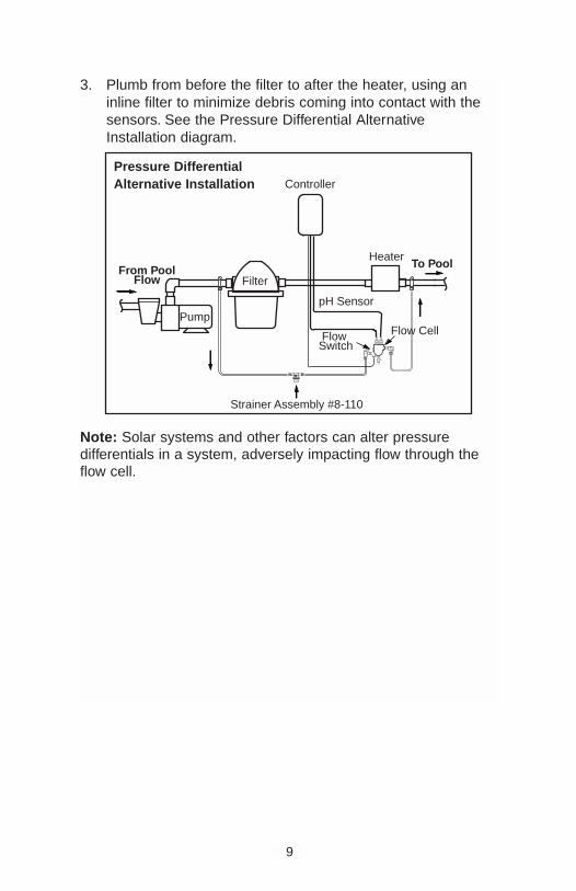
3. Plumb from before the filter to after the heater, using aninline filter to minimize debris coming into contact with thesensors. See the Pressure Differential AlternativeInstallation diagram.
Note: Solar systems and other factors can alter pressure differentials in a system, adversely impacting flow through theflow cell.
Controller
To PoolHeater
pH Sensor
Filter
Pump
From PoolFlow
Flow Switch
Flow Cell
1/8
NPT
Strainer Assembly #8-110
Pressure DifferentialAlternative Installation

10
The flow cell comes fully assembled in the box. It is setup touse with the 3/8" tubing provided; however, other sized tubing or1/2" hard plumbing can be used. To use alternative tubing,remove the 90° on/off valves and plumb according to the appli-cation.
1. If using a saddle clamp, drill a 7/16" hole in the pipe onthe pressure side of the pump. Thread the 1/8" Jaco fitting(#2 in diagram below) through the clamp (#3) and place thenylon jam nut (#4) onto the Jaco fitting. Slide the pipe sealwasher (#5) onto the end of the Jaco fitting. Insert the com-pleted assembly into the hole in the pipe and tighten theclamp. Test for leaks.
If the pipe is larger than 2" in diameter, two clamps joinedtogether will be required per each hole.
If using a pipe tap, drill a 7/16" hole and tap a 1/4" NPThole. Apply RTV silicone, teflon stick or teflon paste to thethreads on the Jaco fitting and screw securely into the pipe.Test for leaks.
2.. Cut the tubing (#1) to the appropriate length. Slightly loosenthe Jaco fitting in the pipe and insert the tubing into it. Takethe free end of the tubing and insert it into the Jaco fittingon the flow switch side of the flow cell.
3. Complete these steps for the return side of the flow cell.Use the appropriate remaining parts to complete this task.Take the free end of the tubing and insert it into the Jaco fitting on the outlet side of the flow cell.
1
5
3
2
4

11
D. Sensor Installation
Carefully unpack the ORP and pHsensors and remove the plastic pro-tective cap(s) from the sensor tip(s).Store the protective cap(s) insidethe controller enclosure for futureuse when winterizing or reshipping.
Slide the sensor inside the compres-sion fitting on the flow cell assemblyor the main pool line so that thesensor tip is below the water line inthe pipe. Tighten the nut of the com-pression fitting until it is finger tight.DO NOT USE A WRENCH.
Attach the sensor connector(s) tothe proper fittings on the controllerbox. (see Figure 4, #7 and #14).
E. ElectricalUse the plug-in transformer provided to attach to the 110V out-let. Low voltage (24V) wiring can be run from the transformeroutput to the controller input. Low voltage wiring can then berun from the controller output to the 24V solenoid valve.
F. Start-up Operations1. Determine the free sanitizer level of your swimming pool or
spa using a DPD test kit. It should be between 1.0 and 3.0ppm—adjust if required.
The controller will not operate if the sanitizer level is below0.2 ppm (below 100 mV).
2. Check the pH level of your pool or spa with a test kit. ThepH should be maintained between 7.2 and 7.6 to maximizesanitizer efficiency and ensure the accuracy of the con-troller. A pH level above or below this range will cause inaccurate sensor readings. High or low pH levels can alsocause irritation to swimmers as well as other problemsassociated with the pool and equipment.
Coil ExtraSensor CableExternally
Controller
Sensor CompressionFitting
PVC Tee
Sensor Tip

12
3. Make sure the power switch (Figure 4, #2) is off and theORP selection knob (Figure 4, #9) is rotated counterclock-wise to the lowest setting.
4. Turn on the filter pump and then the controller power switch.The red power light (Figure 4, #1) and indicator lights on thecontroller light bar array (Figure 4, #8) will come on.
5. Leave the system running for approximately five minutes sothe sensors can get an accurate reading from the pool.
6. Check for leaks and correct as necessary.
G. Sanitizer SettingsBe careful when adjusting the ORP set knob. The dial isextremely sensitive in the 600 to 800 mV range and an adjust-ment of 50 mV could change the sanitizer level by several partsper million.
1. The average pool should have a sanitizer level between 1.0 and 3.0 ppm. This equates to approximately 650 mV onthe controller’s ORP light bar array. If the pool has been balanced correctly, the lights illuminated on the ORP lightbar array should be near 650 mV. Adjust the ORP selectionknob to point at the illuminated light on the ORP light bararray. If more than one light is illuminated, set the knob topoint in between the two lights.
To maintain a higher sanitizer level, set the selection knobabove the light shown on the light bar array. To maintain alower sanitizer level, set the selection knob below the lightshown on the light bar array.
2. Allow the system to operate for 24 hours.
3. With the filtration system running, retest the sanitizer levelusing a test kit and adjust the sanitizer selection knob ifnecessary. It may require two to three days to accurately setthe controller to maintain the ideal sanitizer level.
4. If the chemistry of the pool or spa water changes (e.g. refill-ing, significant changes in pH, build-up of total dissolvedsolids, additions of other chemicals, etc.), the sanitizerselection knob may have to be adjusted.

13
H. pH Calibration1. Take a clean sample of pool water and place the pH sensor
into the water sample.
2. Push the pH display button (Figure 4, #10). The yellow ORPlights on the scale indicator light (Figure 4, #3) will go outand the green pH scale indicator lights will come on. Thelights on the light bar array now correspond to the readingson the pH scale.
When the button is pushed, the controller will monitor thepH for approximately 5 seconds, or for as long as the pHbutton is held down, before returning to the ORP scale.
3. The pH can be calibrated to match the reading taken by the test kit by simultaneously holding down the pH displaybutton and turning the pH calibration set knob (Figure 4,#11) until the lights on the light bar array indicate the pHreading of the test kit.
Sanitizer can now be added to the feeder. See the feederowner’s manual for instructions.

14
VI. Panel Features# DESCRIPTION FUNCTION1 Power On Light Indicates controller is on
2 Power On/Off Switch Turns on the controller
3 Scale Indicators Indicates which scale is being displayed
4 Feed Light Flashes during feed cycle; lit during delay
5 Manual Feed Button Instantly feeds sanitizer
6 Terminal Strip 24 volt input/output
7 ORP Sensor Connector BNC jack
8 Light Bar Array Displays the ORP or pH sensor readings
9 ORP Set Knob Selects the desired ORP level of the water
10 pH Display Button Displays the pH reading for 10 seconds
11 pH Adjustment Knob Calibrates pH sensor
12 Pool/Spa Switch Selects applicable delay cycles
13 Fuse Adjust to match feeder solenoid
14 pH Sensor Connector BNC jack
15. Output 24V to solenoid valve
16 Input 24V to controller
SPA POOLLINE OUTPUT
POWER
ON
OFF
MAINTAINPROPER pH
FEED
MANUAL
pH
ADJ.FEED
C-316 ORP Controller w/pH Display, 24 V
1.5 AMP SLO-BLOHOT COM. GND HOT COM. GND
FUSE
FUSEFUSE
6.6
6.8
7.0
7.27.4 7.6
7.8
8.08.2
8.4
¥20
0¥3
00
¥400 ¥500 ¥600 ¥700 ¥800¥900
¥1000
¥10
0
DEC
REASE ¥INCREASE
OR
P
pH
12
6
1
2
38
9
10
11
4
5
13
147
15
16
Figure 4

15
VII. OperationThe controller will only operate during the filtration cycle.
A. Setting Feed and Delay Times1. The controller is preset at the factory with the following feed
and delay times:Pool Setting: Feed = 1 minute, Delay = 30 secondSpa Setting: Feed = 10 seconds, Delay = 30 seconds
These settings can be adjusted as needed to maintain thepool balance. To modify the factory settings see Pre-Installation, section B.
2. Delays are built into the system to prevent the feeder fromoversanitizing the pool. Once the feeder has dispensed adose of sanitizer, the feeder is unable to dispense again foreither 30 seconds or seven minutes. This delay allows thesanitizer to be circulated through the pool or spa andreturned through the filtration system where the sensors cantest the sanitizer level. After the delay period, another doseof sanitizer will be dispensed if needed.
B. Feed Light Activation1. The yellow feed light (Figure 4, #4) flashes to indicate that
the feeder is active and sanitizer is being dispensed. Duringfeed delays, although no sanitizer is being dispensed. thefeeder is still technically active, so the feed light remainsconstantly lit.
2. Do not adjust the set knob while the feed light is on. Whenthe feed light is on, the lights on the light bar array may register an inaccurate sanitizer level since the system is stillcirculating a dose of sanitizer.

16
C. Out-of-range AlertWhen the ORP is out-of-range (less than 100 mV) for ten con-secutive minutes, the lowest red light on the light bar array willflash and the controller will not activate the feeder. Dependingon the level of ORP, the manual feed button may be used toraise the ORP level.
D. Manual FeedThe manual feed button is mainly used to restart the feed cyclewhen the system shuts down because the ORP level droppedbelow 100 mV (commonly due to an empty feeder or dirty sen-sor). It can also be used to test the solenoid. It cannot be usedwhile the feed light is on, i.e. the feeder is active or in delay.
E. WinterizingIf the system is subject to extended shutdowns or is located incolder climates, it is important to winterize the system.
1. Turn off the main power to the controller.
2. Remove the sensors from the compression fittings. Thesensor tips must be stored in a protective cap or bottlefilled with a liquid solution of one teaspoon salt andthree teaspoons water. Mix the solution thoroughly andmake sure the solution completely covers the sensor tips.STORE SENSORS IN A WARM PLACE - DO NOT SUBJECT SENSORS TO FREEZING TEMPERATURES.
3. Empty the system of all water.
4. If the pool or spa has a flow cell assembly installed, drainthe water from the assembly.
5. Remove all material from the feeder and clean all feeder parts.

17
VIII. MaintenanceA. Testing1. Test the sanitizer and pH levels with a test kit weekly or
more frequently as required by local health codes.
2. Adjust the pH in the pool or spa as needed to maintain alevel between 7.4 and 7.6.
B. Cleaning the Sensor Tips1. It is important to keep the sensor tips clean to ensure
accurate sanitizer level readings. When the sensor tipsbecome dirty, the sensors may read lower than actual sanitizer levels and cause the controller to oversanitize.
Note: A sensor tip coated with scale or oil will not look visibly dirty.
2. As a general rule, the sensor tips should be cleaned everytwo to four weeks for commercial pools and spas, and oncea month for residential pools and spas. Cleaning frequency,however, can vary from one body of water to another. Todetermine the appropriate frequency for your pool or spa,note the light bar reading prior to cleaning. After cleaningthe sensor, allow a stabilizing period of approximately tenminutes. If the light bar reading is identical to the readingprior to cleaning, the sensor was not dirty and the timebetween sensor cleanings can be increased.
3. To clean the sensor tip, turn off the controller and gentlyremove the sensor from the compression fitting. Swirl the tipfor five seconds in muriatic acid (diluted 5 to 1) or whitevinegar, and rinse it in water. DO NOT TOUCH, WIPE ORBRUSH THE END OF THE SENSOR. For commercial poolsand spas, every third cleaning, swirl the sensor tip in a solution of liquid soap and warm water. Rinse with water.
4. Gently replace the sensors and turn on the controller.
5. Allow the controller to operate for a few minutes to get anaccurate reading. Adjust the selection knob if necessary.

18
C. Checking the ORP Sensor1. The ORP sensor should be checked every six months or
anytime the feeder oversanitizes the water.
2. Clean the sensor tip as noted previously.
3. Place the sensor in a clean glass of tap water. This shouldgive a reading between 200 and 400 mV. Adding a smallamount of chlorine should cause the ORP level to jump tobetween 700 and 800 mV.
If the sensor has been sitting in a high concentration ofchlorine for more than 20 hours, it may pick up a ‘memory’.that will not allow it to read below the 500 to 600 mV level.If this is the case, adjust your controller setting accordingly.The sensor should return to normal after a week or two of normal operation. To return it to normal functioning morequickly, place the sensor in a glass of tap water for 72 hours.
4. If the sensor does not respond as indicated, the sensorshould be replaced.
D. Checking the pH Sensor1. The pH sensor should be checked every six months or
anytime the pH goes out of range or cannot be calibrated tothe test kit.
2. Place the sensor in a clean glass of tap water. Add a smallamount of acid to the glass. The pH reading should drop tothe lowest red light. Then place the sensor in any solutionwith a pH above 7.5. The pH reading should move up.
3. If the sensor does not respond as indicated, the sensorshould be replaced.

19
IX. Erosion Feeder Operating Tips• Feeders must be sized properly. When automating an
existing system, multiple feeder may be required. The feed-er should be able to attain desired levels in short operatingcycles. Automation becomes ineffective if the feeder mustrun for prolonged periods.
• The output of erosion feeders is dependent on the erosionrate of the tablets. This erosion rate is dependent on thewater flow, contact area on the tabs, and temperature of the water. Also, bromine tends to erode more slowly than chlorine.
To maximize output:
1. Fully open all valves into and out of the feeder,.
2. Keep the feeder full at all times.
3. If possible, use small tablets, not large pucks.
• Erosion feeders are designed to maintain levels, not to bal-ance the pool's chemistry. Erosion feeders should not beused to bring a pool up to the desired levels. Use liquid orCal Hypo to raise levels to the desired point. Once thedesired level is reached, the erosion feeder can be used tomaintain these levels.
• Feeders must be located on a separate bypass line with acheck valve between the solenoid valve and the feeder. Itis recommended that a flow indicator be placed in thisbypass line.
• The coil/plunger on the solenoid valve should be checked periodically for corrosive buildup that could affectits operation.
• The bypass loop for the feeder may be hooked up frombefore the filter to after the heater. If it is, an inline filter located before the solenoid valve is desirable to pre-vent debris from entering the solenoid valve.
• Erosion feeders are subject to potting (continued tablet dissolution when the flow is off). As a result, the sanitizerconcentration in the feeder can be extremely high. When

20
the solenoid valve opens, the initial flow from the feedermay significantly increase (spike) the sanitizer level in asmall body of water. For this reason, it may be desirable touse the timed-feed feature, which opens the solenoid for ashort period, then delays the next feed cycle until the initialfeed is distributed throughout the pool/spa system.

21
X. TroubleshootingPROBLEM POSSIBLE CAUSE SOLUTION
SANITIZER LEVEL Set knob set too low Adjust knob clockwise until theTOO LOW proper sanitizer level is reached
pH level too low (less than 7.2) Check pH level with a test kit and adjust as required
Chemical feeder empty Refill chemical feeder
Chemical feeder is clogged Clean and dry feeder measuringcup assembly
Defective sensor Replace sensor
SANITIZER LEVEL Set knob set too high Adjust knob counterclockwiseTOO HIGH until the proper sanitizer level
is reached
pH level too high (above 7.8) Check pH level with a test kit and adjust as necessary
Sensor tip is dirty Clean sensor tip
Defective sensor Replace sensor
DISPLAY LIGHTS No power supply Check circuit breaker
OFF

22
XI. Guidelines for Using ORP forWater Maintenance
Q. Why should I maintain a pH level between 7.4 and 7.6?
A. pH levels below 7.4 can cause eye irritation, metal cor-rosion, etching of plaster, stains, damage to vinyl liners,and loss of sanitizer. In addition to eye irritation, pH lev-els above 7.6 can cause cloudy water, scale formationand loss of sanitizer efficiency (low ORP).
Q. How do I increase the pH level?
A. Small amounts of basic (alkaline) chemicals such as pHPlus or pH Up can be added.
Q. How do I lower the pH level?
A. Small amounts of liquid acid (muriatic) or dry acid (sodi-um bisulfate) such as pH Minus or pH Down can be added.
Q. How does 650 mV relate to the ppm of chlorine?
A. Pure water, without conditioner, at a pH level of 7.5 cor-responds to approximately 1.5 ppm of chlorine. Actualpool or spa water usually takes at least 1-2 ppm of chlo-rine to generate 650 mV ORP, although the TotalDissolved Solids and pH can affect the activity of thechlorine and thus change the level of ORP.
Q. Does an ORP of 650 mV stop algae?
A. No. Because algae is a living organism that adaptsgenetically to a constant level of sanitizer, the periodicaddition of an algicide or shocking may be necessary.Please note that the addition of some chemicals canchange the ORP readings for up to several days.
Q. What causes a low ORP?
A. A low sanitizer level, a pH level above 7.6, a conditionerlevel above 200 ppm or a TDS (Total Dissolved Solids)above 3,000 ppm can all cause a low ORP.

23
Q. How do I make sure the ORP sensor is working properly?
A. Watch the sensor reading when adding sanitizer. If itdoes not respond properly, follow the recommendedcleaning procedures, see Maintenance. If cleaning doesnot solve the problem, check the sensor as outlined inthe Maintenance section.
Q. How should the ORP sensor respond to adding acid?
A. Adding acid decreases the pH level thus increasing the ORP.
Q. How should the ORP sensor respond to adding base?
A. Adding base increases the pH level thus decreasing the ORP.
Q. How should the ORP sensor respond to adding sanitizer?
A. Depending upon the type of sanitizer used, the ORPshould increase. A sanitizer high in base, such as liquidchlorine (sodium hypochlorite) or a dry chlorine powder(calcium hypochlorite), however, can cause the pH levelto rise and the ORP to decrease. The pH level must bein the ideal range to maintain the proper ORP level.
Q. Can ORP be used with ozone?
A. Even though ozone is an excellent oxidizer, it has avery short lifetime. Therefore, a chlorine or bromineresidual will still be needed in order to maintain theproper ORP level. When using ozone, the ozone mustbe introduced into the system downstream from the sensors.
Q. Can ORP be used with UV or metal ions?
A. Only if the proper chlorine or bromine residual is maintained.

24
XII.WARRANTYPolaris Watermatic C316 ControllerThis limited warranty is extended to the original consumer purchaser of this Polaris Watermatic C316 Controller manufactured by Polaris Pool Systems, Inc., 2620 CommerceWay, Vista, CA 92083-8438, USA.
Polaris Pool Systems warrants the Watermatic Controller it manufactures, including all parts and components thereof, to befree of defects in material and workmanship. For questionsregarding your Polaris Watermatic Controller, please feel free tocall or write us. Be sure to provide the serial number of your unit.
The warranty commences on the date of installation of the con-troller and shall remain in effect for a period of one (1) year, butin no event shall it be in effect for more than two (2) years fromthe date of manufacture of the controller as established by theserial number.
This limited warranty does not apply if the failure is caused orcontributed by any of the following: improper handling, improperstorage, abuse, unsuitable application of the unit, lack of rea-sonable and necessary maintenance, winter freezing or repairsmade or attempted by other than Polaris Pool Systems or oneof its authorized service centers. Polaris will repair or replace, atits option, a unit or part proved to be defective within the war-ranty period and under the conditions of the warranty.
Unless local repair is authorized, the consumer must deliver orship the unit or the warranty parts, freight prepaid to the nearestPolaris Authorized Service Center or return it freight prepaid(after proper authorization) to the plant of manufacture.Authorization to return a unit to the plant of manufacture mustbe obtained from the Polaris Customer Service Department.For your convenience, please check with your dealer for thelocal procedure before exercising this warranty. If further direc-tions or instructions should be required, contact the CustomerService Department at 1-800-VAC-SWEEP (USA and Canadaonly) or 760-599-9600. Be sure to insure your shipmentsagainst loss or damage during transit.

25
Polaris is not responsible for the cost of removal of the unit,damages due to removal, any other expenses incurred in ship-ping the unit or parts to or from the factory or its authorizedservice centers, the installation of the repaired or replacementunit. The consumer must bear these expenses.
This warranty does not cover repair or replacement of a unitexcept at our factory or a Polaris Authorized Service Center.
THIS LIMITED WARRANTY IS IN LIEU OF ALL OTHER WAR-RANTIES, EXPRESS OR IMPLIED, INCLUDING THE IMPLIEDWARRANTIES OF MERCHANTABILITY AND FITNESS FOR APARTICULAR PURPOSE, AND ALL SUCH OTHER WAR-RANTIES ARE DISCLAIMED EXCEPT TO THE EXTENT ANYIMPLIED WARRANTY MAY BE IMPOSED BY STATE CON-SUMER LAW. ANY SUCH IMPLIED WARRANTY IMPOSEDBY STATE CONSUMER LAW IS LIMITED IN DURATION TOONE (1) YEAR FROM DATE OF PURCHASE.
IN NO EVENT SHALL POLARIS POOL SYSTEMS BE LIABLEFOR INCIDENTAL OR CONSEQUENTIAL DAMAGES OF ANYNATURE OR KIND OR FOR DAMAGES TO PERSONS ORPROPERTY, INCLUDING ANY DAMAGE RESULTING FROMTHE USE OF THE POLARIS WATERMATIC CONTROLLER.
Some states do not allow limitations on how long an impliedwarranty lasts, or the exclusion or limitation of incidental or consequential damages, so the above limitations may not applyto you.
This limited warranty is valid only in the United States ofAmerica and Canada, and it does not apply to PolarisWatermatic Controllers sold or installed in any other country.

© 2003 Polaris Pool Systems, Inc. All rights reserved TL-413 1/03