Embed Size (px)
Citation preview
24
The upcoming 802.11ax standard introduces new techniques to more efficiently utilize the unlicensed
2.4 GHz and 5 GHz bands. Public WLAN networks will especially benefit from the standard.
WLAN 802.11ax speeds up communica-tions in multi-user scenarios
BackgroundThe number of WLAN-capable devices has risen drastically in the past few years, and the growth rate is expected to increase. This is because, in addition to laptops, smartphones and tables, an ever greater number of televisions, game consoles, cam-eras, smart home devices and IoT devices are connecting to WLANs. This will increase the density of users in networks, leading to a noticeable reduction in the data throughput due to packet collisions and shorter “free” time periods during which a subscriber can transmit. WLAN routers (access points, AP) in apartment buildings have the same effect because they are very close to each other and act as interferers.
To alleviate these problems, the IEEE is currently working on a new WLAN standard: 802.11ax. Previous standards (802.11g / n / ac) increased data throughput primarily by enhancing physical parameters such as bandwidth and mod-ulation factor or by introducing new transmission methods such as multiple input multiple output (MIMO). 802.11ax will not introduce any essential changes in this area. Instead, the new standard focuses on making networks more efficient and on better utilizing existing transmission capacities.
802.11axThe standard is currently in the planning phase and is pro-jected for completion by the end of 2018. The key players in the WLAN market already started developing 802.11ax-capa-ble chipsets in 2016. Although draft version 1.0 of the stan-dard did not receive a majority vote by the IEEE working group in early 2017, the first devices are expected on the mar-ket even before the standard receives final approval.
802.11ax aims to increase the performance of intensively used networks, especially those for: ❙ Airports and train stations ❙ Local and long-distance public transportation ❙ Stadiums and concert halls ❙ Apartment buildings
This article presents the changes that 802.11ax will make to the physical layer (Fig. 1) (for changes to the MAC layer, refer to the draft of the standard [1] and to the specification frame-work document [2]).
The focus is increasingly on outdoor applications. Outdoor transmission channels exhibit stronger multipath propaga-tion and longer echo times. To prevent intersymbol interfer-ence in this scenario, an optional transmission scheme will be introduced in which the guard interval and symbol dura-tion are lengthened by a factor of four while the subcarrier offset is reduced by one fourth, keeping the transmission rate the same but improving resistance to fading. Under opti-mal conditions, 802.11ax can achieve a maximum data rate of 1200 Mbit/s on a single channel by using the newly intro-duced 1024QAM modulation and a shorter guard interval. With 8 × 8 MIMO, 9.6 Gbit/s is theoretically possible. Even in its optimal configuration, 802.11ac achieves “only” 6.9 Gbit/s.
OFDMAThe most significant change is the introduction of orthogonal frequency division multiple access (OFDMA) in the uplink and downlink, where multiple users transmit simultaneously and share the available bandwidth of a channel. Previous stan-dards use OFDM and time division multiplexing, i.e. only one user transmits over the full bandwidth.
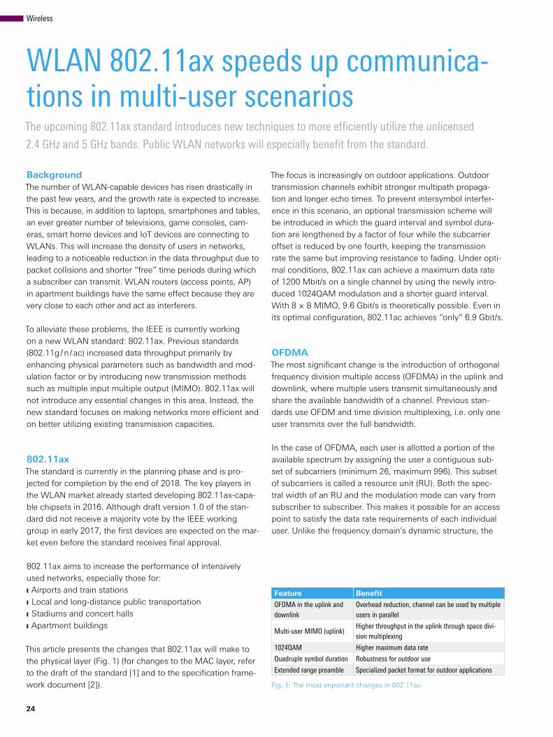
In the case of OFDMA, each user is allotted a portion of the available spectrum by assigning the user a contiguous sub-set of subcarriers (minimum 26, maximum 996). This subset of subcarriers is called a resource unit (RU). Both the spec-tral width of an RU and the modulation mode can vary from subscriber to subscriber. This makes it possible for an access point to satisfy the data rate requirements of each individual user. Unlike the frequency domain’s dynamic structure, the
Feature Benefit
OFDMA in the uplink and downlink
Overhead reduction, channel can be used by multiple users in parallel
Multi-user MIMO (uplink)Higher throughput in the uplink through space divi-sion multiplexing
1024QAM Higher maximum data rate
Quadruple symbol duration Robustness for outdoor use
Extended range preamble Specialized packet format for outdoor applications
Fig. 1: The most important changes in 802.11ax.
Wireless
Resource units
Central RU 26
DC subcarriers
20 MHz
a)
b)
26 26 26 26 13 26 26 26 2613
52 52 52 5213 13
106 10613 13
242
106 13 13 52 26 26
Transmission modes
AP
HE_SU/HE_EXT_SU
Downlink
Uplink
HE_SU / HE_EXT_SU
Single user Multi-user
STA AP
HE_MU
Downlink
Uplink
HE_TRIG
STA
time axis has a uniform structure: to prevent interference, the data packets in all RUs have the same length and are trans-mitted synchronously. Users that have less data to transmit than permitted by the packet length must pad the packet with padding bits.
Fig. 2 shows the possible resource unit configurations for a 20 MHz channel. The smallest RU size of RU 26 allows up to nine users to transmit simultaneously (see the top row in the figure). The maximum bandwidth is 160 MHz, permitting up to 74 simultaneous users.
A single active user is a special scenario in OFDMA in which a resource unit is allocated the entire bandwidth (RU 242 in the figure).
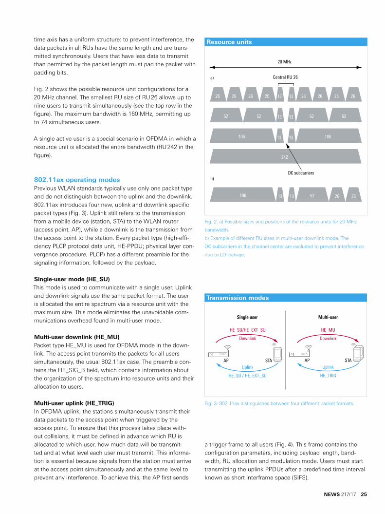
802.11ax operating modesPrevious WLAN standards typically use only one packet type and do not distinguish between the uplink and the downlink. 802.11ax introduces four new, uplink and downlink specific packet types (Fig. 3). Uplink still refers to the transmission from a mobile device (station, STA) to the WLAN router (access point, AP), while a downlink is the transmission from the access point to the station. Every packet type (high-effi-ciency PLCP protocol data unit, HE-PPDU; physical layer con-vergence procedure, PLCP) has a different preamble for the signaling information, followed by the payload.
Single-user mode (HE_SU)This mode is used to communicate with a single user. Uplink and downlink signals use the same packet format. The user is allocated the entire spectrum via a resource unit with the maximum size. This mode eliminates the unavoidable com-munications overhead found in multi-user mode.
Multi-user downlink (HE_MU)Packet type HE_MU is used for OFDMA mode in the down-link. The access point transmits the packets for all users simultaneously, the usual 802.11ax case. The preamble con-tains the HE_SIG_B field, which contains information about the organization of the spectrum into resource units and their allocation to users.
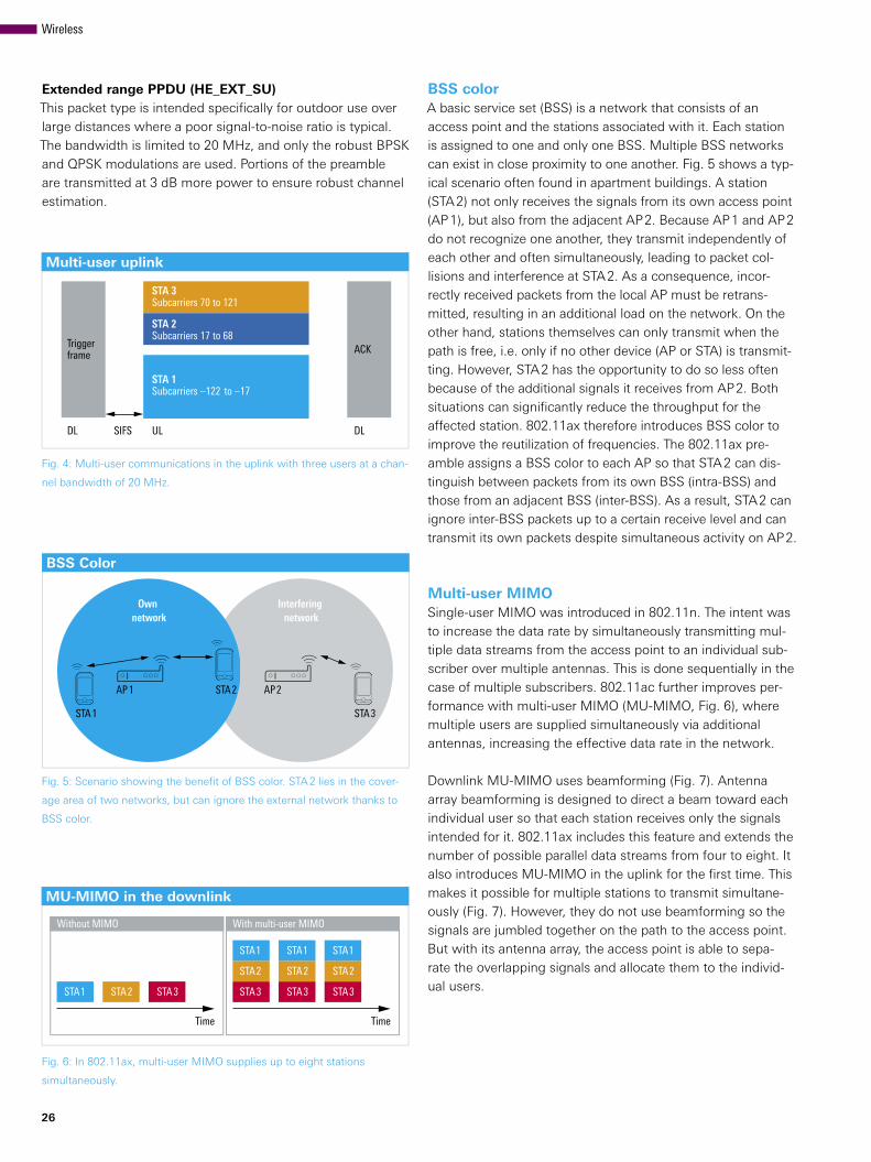
Multi-user uplink (HE_TRIG)In OFDMA uplink, the stations simultaneously transmit their data packets to the access point when triggered by the access point. To ensure that this process takes place with-out collisions, it must be defined in advance which RU is allocated to which user, how much data will be transmit-ted and at what level each user must transmit. This informa-tion is essential because signals from the station must arrive at the access point simultaneously and at the same level to prevent any interference. To achieve this, the AP first sends
a trigger frame to all users (Fig. 4). This frame contains the configuration parameters, including payload length, band-width, RU allocation and modulation mode. Users must start transmitting the uplink PPDUs after a predefined time interval known as short interframe space (SIFS).
Fig. 2: a) Possible sizes and positions of the resource units for 20 MHz
bandwidth.
b) Example of different RU sizes in multi-user downlink mode. The
DC subcarriers in the channel center are excluded to prevent interference
due to LO leakage.
Fig. 3: 802.11ax distinguishes between four different packet formats.
NEWS 217/17 25
BSS Color
AP2
STA3
Own network
Interfering network
STA2AP1
STA1
MU-MIMO in the downlink
Time
Without MIMO
Time
With multi-user MIMO
STA1 STA2 STA3 STA3 STA3 STA3
STA2 STA2 STA2
STA1 STA1 STA1
Multi-user uplink
STA 3Subcarriers 70 to 121
STA 2Subcarriers 17 to 68
STA 1Subcarriers –122 to –17
UL
ACK
DL
Triggerframe
DL SIFS
26
Extended range PPDU (HE_EXT_SU)This packet type is intended specifically for outdoor use over large distances where a poor signal-to-noise ratio is typical. The bandwidth is limited to 20 MHz, and only the robust BPSK and QPSK modulations are used. Portions of the preamble are transmitted at 3 dB more power to ensure robust channel estimation.
Fig. 4: Multi-user communications in the uplink with three users at a chan-
nel bandwidth of 20 MHz.
Fig. 5: Scenario showing the benefit of BSS color. STA 2 lies in the cover-
age area of two networks, but can ignore the external network thanks to
BSS color.
Fig. 6: In 802.11ax, multi-user MIMO supplies up to eight stations
simultaneously.
BSS colorA basic service set (BSS) is a network that consists of an access point and the stations associated with it. Each station is assigned to one and only one BSS. Multiple BSS networks can exist in close proximity to one another. Fig. 5 shows a typ-ical scenario often found in apartment buildings. A station (STA 2) not only receives the signals from its own access point (AP 1), but also from the adjacent AP 2. Because AP 1 and AP 2 do not recognize one another, they transmit independently of each other and often simultaneously, leading to packet col-lisions and interference at STA 2. As a consequence, incor-rectly received packets from the local AP must be retrans-mitted, resulting in an additional load on the network. On the other hand, stations themselves can only transmit when the path is free, i.e. only if no other device (AP or STA) is transmit-ting. However, STA 2 has the opportunity to do so less often because of the additional signals it receives from AP 2. Both situations can significantly reduce the throughput for the affected station. 802.11ax therefore introduces BSS color to improve the reutilization of frequencies. The 802.11ax pre-amble assigns a BSS color to each AP so that STA 2 can dis-tinguish between packets from its own BSS (intra-BSS) and those from an adjacent BSS (inter-BSS). As a result, STA 2 can ignore inter-BSS packets up to a certain receive level and can transmit its own packets despite simultaneous activity on AP 2.
Multi-user MIMOSingle-user MIMO was introduced in 802.11n. The intent was to increase the data rate by simultaneously transmitting mul-tiple data streams from the access point to an individual sub-scriber over multiple antennas. This is done sequentially in the case of multiple subscribers. 802.11ac further improves per-formance with multi-user MIMO (MU-MIMO, Fig. 6), where multiple users are supplied simultaneously via additional antennas, increasing the effective data rate in the network.
Downlink MU-MIMO uses beamforming (Fig. 7). Antenna array beamforming is designed to direct a beam toward each individual user so that each station receives only the signals intended for it. 802.11ax includes this feature and extends the number of possible parallel data streams from four to eight. It also introduces MU-MIMO in the uplink for the first time. This makes it possible for multiple stations to transmit simultane-ously (Fig. 7). However, they do not use beamforming so the signals are jumbled together on the path to the access point. But with its antenna array, the access point is able to sepa-rate the overlapping signals and allocate them to the individ-ual users.
Wireless
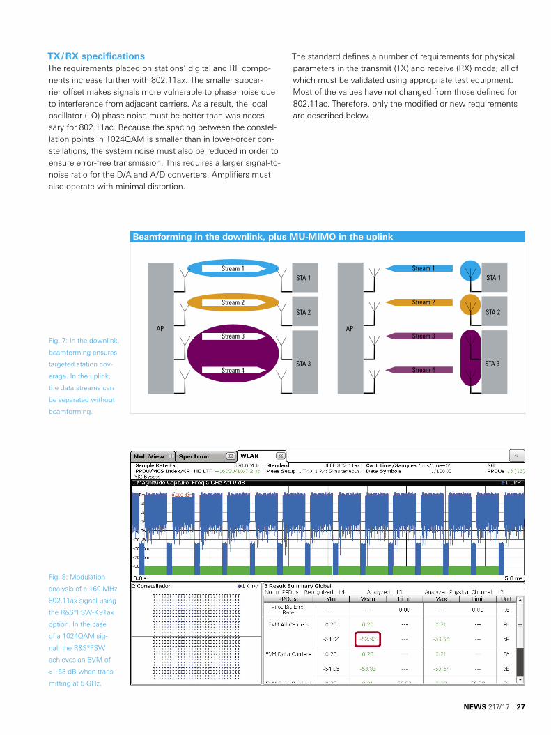
Beamforming in the downlink, plus MU-MIMO in the uplink
AP
STA 1
STA 2
STA 3
AP
STA 1
STA 2
STA 3
Stream 1
Stream 2
Stream 3
Stream 4
Stream 1
Stream 2
Stream 3
Stream 4
TX / RX specificationsThe requirements placed on stations’ digital and RF compo-nents increase further with 802.11ax. The smaller subcar-rier offset makes signals more vulnerable to phase noise due to interference from adjacent carriers. As a result, the local oscillator (LO) phase noise must be better than was neces-sary for 802.11ac. Because the spacing between the constel-lation points in 1024QAM is smaller than in lower-order con-stellations, the system noise must also be reduced in order to ensure error-free transmission. This requires a larger signal-to-noise ratio for the D/A and A/D converters. Amplifiers must also operate with minimal distortion.
The standard defines a number of requirements for physical parameters in the transmit (TX) and receive (RX) mode, all of which must be validated using appropriate test equipment. Most of the values have not changed from those defined for 802.11ac. Therefore, only the modified or new requirements are described below.
Fig. 7: In the downlink,
beamforming ensures
targeted station cov-
erage. In the uplink,
the data streams can
be separated without
beamforming.
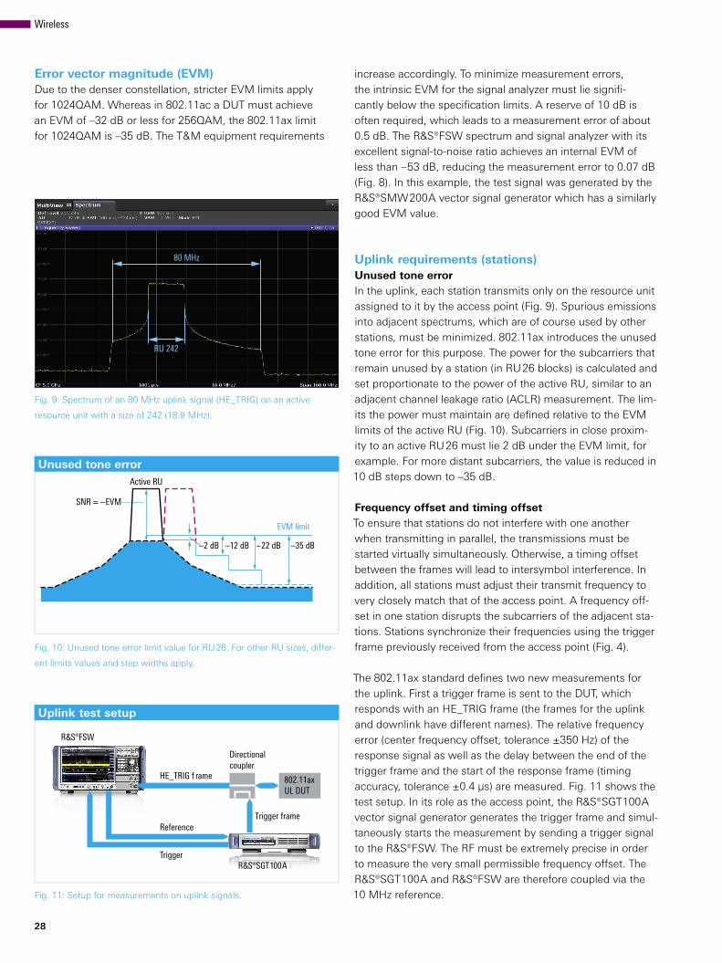
Fig. 8: Modulation
analysis of a 160 MHz
802.11ax signal using
the R&S®FSW-K91ax
option. In the case
of a 1024QAM sig-
nal, the R&S®FSW
achieves an EVM of
< –53 dB when trans-
mitting at 5 GHz.
NEWS 217/17 27
80 MHz
RU 242
Unused tone error
–2 dB –12 dB –22 dB
Noise and distortion
EVM limit
–35 dB
Active RU
SNR = –EVM
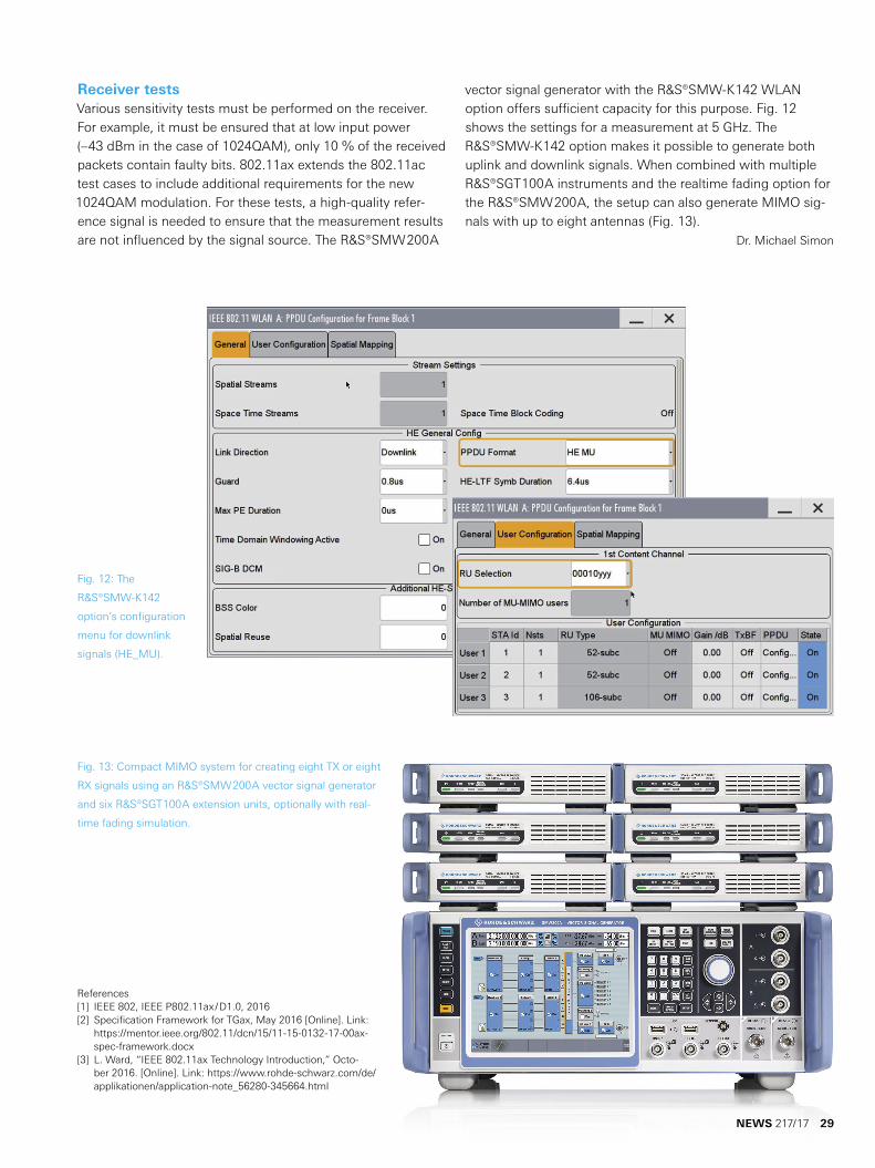
Uplink test setup
ReferenceTrigger frame
Directional coupler
Trigger
HE_TRIG f rame
¸FSW
¸SGT100A
802.11axUL DUT
28
Error vector magnitude (EVM)Due to the denser constellation, stricter EVM limits apply for 1024QAM. Whereas in 802.11ac a DUT must achieve an EVM of –32 dB or less for 256QAM, the 802.11ax limit for 1024QAM is –35 dB. The T&M equipment requirements
Fig. 9: Spectrum of an 80 MHz uplink signal (HE_TRIG) on an active
resource unit with a size of 242 (18.9 MHz).
Fig. 10: Unused tone error limit value for RU 26. For other RU sizes, differ-
ent limits values and step widths apply.
Fig. 11: Setup for measurements on uplink signals.
increase accordingly. To minimize measurement errors, the intrinsic EVM for the signal analyzer must lie signifi-cantly below the specification limits. A reserve of 10 dB is often required, which leads to a measurement error of about 0.5 dB. The R&S®FSW spectrum and signal analyzer with its excellent signal-to-noise ratio achieves an internal EVM of less than –53 dB, reducing the measurement error to 0.07 dB (Fig. 8). In this example, the test signal was generated by the R&S®SMW200A vector signal generator which has a similarly good EVM value.
Uplink requirements (stations)Unused tone errorIn the uplink, each station transmits only on the resource unit assigned to it by the access point (Fig. 9). Spurious emissions into adjacent spectrums, which are of course used by other stations, must be minimized. 802.11ax introduces the unused tone error for this purpose. The power for the subcarriers that remain unused by a station (in RU 26 blocks) is calculated and set proportionate to the power of the active RU, similar to an adjacent channel leakage ratio (ACLR) measurement. The lim-its the power must maintain are defined relative to the EVM limits of the active RU (Fig. 10). Subcarriers in close proxim-ity to an active RU 26 must lie 2 dB under the EVM limit, for example. For more distant subcarriers, the value is reduced in 10 dB steps down to –35 dB.
Frequency offset and timing offsetTo ensure that stations do not interfere with one another when transmitting in parallel, the transmissions must be started virtually simultaneously. Otherwise, a timing offset between the frames will lead to intersymbol interference. In addition, all stations must adjust their transmit frequency to very closely match that of the access point. A frequency off-set in one station disrupts the subcarriers of the adjacent sta-tions. Stations synchronize their frequencies using the trigger frame previously received from the access point (Fig. 4).
The 802.11ax standard defines two new measurements for the uplink. First a trigger frame is sent to the DUT, which responds with an HE_TRIG frame (the frames for the uplink and downlink have different names). The relative frequency error (center frequency offset, tolerance ±350 Hz) of the response signal as well as the delay between the end of the trigger frame and the start of the response frame (timing accuracy, tolerance ±0.4 µs) are measured. Fig. 11 shows the test setup. In its role as the access point, the R&S®SGT100A vector signal generator generates the trigger frame and simul-taneously starts the measurement by sending a trigger signal to the R&S®FSW. The RF must be extremely precise in order to measure the very small permissible frequency offset. The R&S®SGT100A and R&S®FSW are therefore coupled via the 10 MHz reference.
Wireless
Receiver testsVarious sensitivity tests must be performed on the receiver. For example, it must be ensured that at low input power (–43 dBm in the case of 1024QAM), only 10 % of the received packets contain faulty bits. 802.11ax extends the 802.11ac test cases to include additional requirements for the new 1024QAM modulation. For these tests, a high-quality refer-ence signal is needed to ensure that the measurement results are not influenced by the signal source. The R&S®SMW200A
Fig. 12: The
R&S®SMW-K142
option’s configuration
menu for downlink
signals (HE_MU).
Fig. 13: Compact MIMO system for creating eight TX or eight
RX signals using an R&S®SMW200A vector signal generator
and six R&S®SGT100A extension units, optionally with real-
time fading simulation.
References[1] IEEE 802, IEEE P802.11ax/D1.0, 2016[2] Specification Framework for TGax, May 2016 [Online]. Link:
https://mentor.ieee.org/802.11/dcn/15/11-15-0132-17-00ax-spec-framework.docx
[3] L. Ward, “IEEE 802.11ax Technology Introduction,” Octo-ber 2016. [Online]. Link: https://www.rohde-schwarz.com/de/applikationen/application-note_56280-345664.html
vector signal generator with the R&S®SMW-K142 WLAN option offers sufficient capacity for this purpose. Fig. 12 shows the settings for a measurement at 5 GHz. The R&S®SMW-K142 option makes it possible to generate both uplink and downlink signals. When combined with multiple R&S®SGT100A instruments and the realtime fading option for the R&S®SMW200A, the setup can also generate MIMO sig-nals with up to eight antennas (Fig. 13).
Dr. Michael Simon
NEWS 217/17 29


![VRIF Guidelines 2 · 2020. 6. 4. · Amendment Enhancements for High Efficiency WLAN (IEEE 802.11ax) [ACN] Ambisonic data exchange formats – Ambisonic Channel Number (Wikipedia)](https://img.pdfslide.us/doc/110x75/5fc06d1b5a042e3fdb268930/vrif-guidelines-2-2020-6-4-amendment-enhancements-for-high-efficiency-wlan.jpg)