Embed Size (px)
Citation preview
IEEE 802.11ax Technology Introduction White Paper
This white paper provides an introduction to the technology used in the 802.11ax amendment to the 802.11
standard and an overview of receiver and transmitter test requirements. IEEE 802.11ax, also known as
High Efficiency Wireless (HEW), provides mechanisms to more efficiently utilize the unlicensed spectrum
bands (2.4 and 5 GHz) and improve user experience.
Note:
Please find the most up-to-date document on our homepage
http://www.rohde-schwarz.com/appnote/1MA222
Whi
te P
aper
Lisa
War
d
10.2
016 –
1MA
222_
0e
Table of Contents
1MA222_0e Rohde & Schwarz IEEE 802.11ax Technology Introduction
2
Table of Contents
1 Introduction ......................................................................................... 3
2 IEEE 802.11ax Core Documents ........................................................ 4
3 IEEE 802.11ax Goals & Features ....................................................... 5
4 802.11ax (High Efficiency PHY) ......................................................... 6
4.1 PPDU Formats .............................................................................................................. 7
4.2 From Single User to Multiple Users (MU) ................................................................10
4.2.1 Subcarrier Types..........................................................................................................12
4.2.2 OFDMA Downlink Resource Unit Assignments ...........................................................15
4.2.3 OFDMA Uplink Resource Unit Assignments ...............................................................21
5 802.11ax Measurements ................................................................... 24
5.1 802.11ax Transmitter Specification..........................................................................24
5.1.1 Transmit Spectrum Mask .............................................................................................24
5.1.2 Spectral Flatness .........................................................................................................26
5.1.3 Transmitter Modulation Accuracy ................................................................................27
5.2 HE Receiver Requirements .......................................................................................29
5.3 HE Trigger Based PPDU Specifications ..................................................................30
5.3.1 Transmit Power Accuracy and RSSI ...........................................................................30
5.3.2 Carrier Frequency Offset (CFO) error and timing drift .................................................31
6 Literature ........................................................................................... 32
6.1 References ..................................................................................................................32
7 Abbreviations/Acronyms/Initialisms ............................................... 33
Introduction PPDU Formats
1MA222_0e Rohde & Schwarz IEEE 802.11ax Technology Introduction
3
1 Introduction
IEEE 802.11 is the IEEE working group developing Wireless Local Area Network
specifications. The group began work in the late 1990s and since then has created
several successful standards/amendments including 802.11a, b and g.
WLAN is now ubiquitous, with one or more of these WLAN technologies included as
standard capabilities on most laptops and many smartphones. The IEEE 802.11 group
has continued to build and improve on the earlier a/b and g with the official approval of
802.11n in 2009 and 802.11ac in 2013. There is a drawback to this success, however.
Because WLAN is everywhere, it is not uncommon to find many access points and
stations located in dense locations such as apartment buildings and stadiums. Since
WLAN uses spectrum in the unlicensed ISM band it is likely that several connections
may interfere each other and cause some capacity crunch. There is no common
scheduler in WLAN, and the channel access uses a CSMA scheme which has some
drawbacks in high occupancy scenarios. In addition, users utilize WLAN for many
different applications such as video streaming and offloading.
To accommodate the challenging applications and the large number of WLAN users in
dense locations, the 802.11 working group formed the HEW (High Efficiency Wireless)
study group in 2013 to find ways to improve the user experience for these applications
and to more efficiently use the 2.4 and 5 GHz spectrum. In March, 2014, the HEW
study group became an official task group, Task Group 11ax, to develop the 802.11ax
amendment to 802.11-2012.
This technology introduction paper contains 4 main parts: 1. Core documents for the
11ax amendment development, 2. 11ax goals and features, 3. Technology overview
that covers key new parts of the IEEE 802.11ax draft, and 4. Test requirements for
measuring key metrics such as EVM and adjacent channel rejection. It is important to
note that the 802.11ax amendment is still in early development stages and will likely
change until a stable version of the amendment is available. Typically, draft v2.0 of an
802.11 amendment is considered stable, and 802.11ax draft v2.0 is expected to be
complete in March of 2017.
IEEE 802.11ax Core Documents PPDU Formats
1MA222_0e Rohde & Schwarz IEEE 802.11ax Technology Introduction
4
2 IEEE 802.11ax Core Documents
Much of the information in this paper comes from two key 802.11ax “Core” Documents.
The 802.11ax draft version 0.4 and the 802.11ax Specification Framework Document
version 17.
The 802.11ax amendment draft v0.4 [1] contains the proposed changes to 802.11mc
draft version 7 in order to meet the 802.11ax requirements and goals. These changes
include a new clause for the PHY specifications as well as a new MAC clause for
supporting the new PHY features. In addition, the 11ax amendment contains
modifications to the current 802.11 MAC layer in order to maintain compatibility with
legacy devices. P802.11ax Draft Version 0.4 was released August 30, 2016. The
expected completion date for the final amendment version is late 2018.
The 802.11ax Specification Framework Document contains the features and
requirements that were agreed to by the 802.11ax task group members and is used as
the ‘framework’ or outline of the 802.11ax amendment. While the 802.11ax working
draft is only available to voting members of the IEEE 802.11 Working Group, the
Specification Framework Document can be obtained by all at this link:
https://mentor.ieee.org/802.11/dcn/15/11-15-0132-17-00ax-spec-framework.docx. In
addition the 802.11 task groups provide public status updates of their work. The
802.11ax status can be found at: http://www.ieee802.org/11/Reports/tgax_update.htm.
IEEE 802.11ax Goals & Features PPDU Formats
1MA222_0e Rohde & Schwarz IEEE 802.11ax Technology Introduction
5
3 IEEE 802.11ax Goals & Features
The main goal of 802.11ax is to improve the user experience and network performance
in dense deployments in the 2.4 and 5 GHz band. Specific targets (as defined in the
Project Authorization Request [2]) are:
ı At least four times improvement in the average throughput per station
(measured at the MAC data service access point) in a dense deployment
scenario, while maintaining or improving the power efficiency per station
ı Backwards compatibility and coexistence with legacy 802.11 devices
operating in the same band
802.11ax will use the spectrum efficiency, area throughput and performance
improvements to target several usage models including: (See [3]):
1. Airport/Train station 2. E-Education 3. Public transportation 4. Dense apartment building 5. Pico cell street deployments
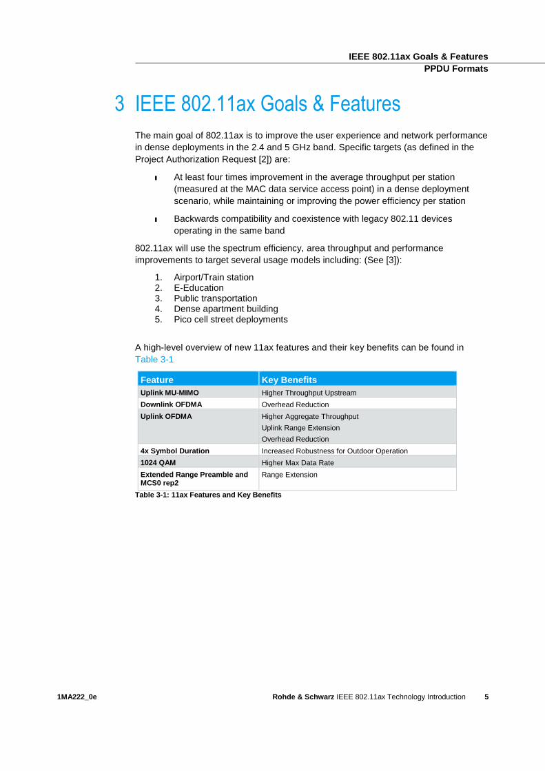
A high-level overview of new 11ax features and their key benefits can be found in
Table 3-1
Feature Key Benefits
Uplink MU-MIMO Higher Throughput Upstream
Downlink OFDMA Overhead Reduction
Uplink OFDMA Higher Aggregate Throughput
Uplink Range Extension
Overhead Reduction
4x Symbol Duration Increased Robustness for Outdoor Operation
1024 QAM Higher Max Data Rate
Extended Range Preamble and MCS0 rep2
Range Extension
Table 3-1: 11ax Features and Key Benefits
802.11ax (High Efficiency PHY) PPDU Formats
1MA222_0e Rohde & Schwarz IEEE 802.11ax Technology Introduction
6
4 802.11ax (High Efficiency PHY)
An HE (High Efficiency) device will be required to comply with mandatory requirements
of the legacy WLAN PHY layers. That is, an HE device operating in 2.4 GHz will need
to comply with the 802.11n PHY requirements and an HE device operating in the 5
GHz band will be required to be compliant with the 802.11n and 802.11ac PHY
specifications.
Despite this compliance requirement, there are significant changes in 802.11ax from
previous 802.11 generations. One of the main differences is the addition of support for
MU-MIMO (Multi User-MIMO) in the uplink as well as downlink and OFDMA
(Orthogonal Frequency Division Multiple Access.) Another change in 11ax is the
symbol time which is 12.8 us - four times the legacy symbol time of 3.2 us.
Three main reasons for increasing the symbol time are [4] :
ı Robustness in outdoor channels
ı Greater tolerance to timing jitter across users in UL MU-MIMO/OFDMA
ı Higher indoor efficiency (by lowering CP overhead)
Along with the increased symbol time, 11ax mandates support for three cyclic prefix
(CP) times:
ı 0.8 us: using this legacy CP time with the longer symbol time improves
efficiency since there is less overhead from the CP
ı 1.6 us: targeting high efficiency in outdoor channels and indoor UL MU-
MIMO/OFDMA
ı 3.2 us: targeting robustness in the more demanding case of outdoor UL MU-
MIMO/OFDMA
In consequence of the higher symbol time the subcarrier spacing decreases from
312.5 KHz to 78.125 KHz and the FFT size for a channel bandwidth of 20 MHz
increases from 64 to 256. A narrow subcarrier spacing allows better equalization and
thus a higher channel robustness. Although a larger FFT size could have been used,
the implementation complexities increase as FFT increases. In addition, as the
subcarrier spacing becomes smaller, the CFO (Carrier Frequency Offset) correction
needs to be more precise.
802.11ax (High Efficiency PHY) PPDU Formats
1MA222_0e Rohde & Schwarz IEEE 802.11ax Technology Introduction
7
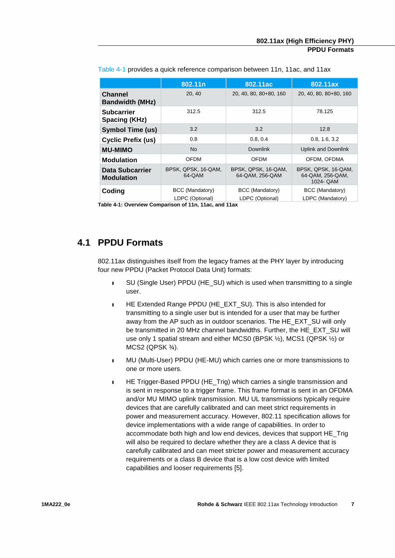
Table 4-1 provides a quick reference comparison between 11n, 11ac, and 11ax
802.11n 802.11ac 802.11ax
Channel Bandwidth (MHz)
20, 40 20, 40, 80, 80+80, 160 20, 40, 80, 80+80, 160
Subcarrier Spacing (KHz)
312.5 312.5 78.125
Symbol Time (us) 3.2 3.2 12.8
Cyclic Prefix (us) 0.8 0.8, 0.4 0.8, 1.6, 3.2
MU-MIMO No Downlink Uplink and Downlink
Modulation OFDM OFDM OFDM, OFDMA
Data Subcarrier Modulation
BPSK, QPSK, 16-QAM, 64-QAM
BPSK, QPSK, 16-QAM, 64-QAM, 256-QAM
BPSK, QPSK, 16-QAM, 64-QAM, 256-QAM,
1024- QAM
Coding BCC (Mandatory)
LDPC (Optional)
BCC (Mandatory)
LDPC (Optional)
BCC (Mandatory)
LDPC (Mandatory)
Table 4-1: Overview Comparison of 11n, 11ac, and 11ax
4.1 PPDU Formats
802.11ax distinguishes itself from the legacy frames at the PHY layer by introducing
four new PPDU (Packet Protocol Data Unit) formats:
ı SU (Single User) PPDU (HE_SU) which is used when transmitting to a single
user.
ı HE Extended Range PPDU (HE_EXT_SU). This is also intended for
transmitting to a single user but is intended for a user that may be further
away from the AP such as in outdoor scenarios. The HE_EXT_SU will only
be transmitted in 20 MHz channel bandwidths. Further, the HE_EXT_SU will
use only 1 spatial stream and either MCS0 (BPSK ½), MCS1 (QPSK ½) or
MCS2 (QPSK ¾).
ı MU (Multi-User) PPDU (HE-MU) which carries one or more transmissions to
one or more users.
ı HE Trigger-Based PPDU (HE_Trig) which carries a single transmission and
is sent in response to a trigger frame. This frame format is sent in an OFDMA
and/or MU MIMO uplink transmission. MU UL transmissions typically require
devices that are carefully calibrated and can meet strict requirements in
power and measurement accuracy. However, 802.11 specification allows for
device implementations with a wide range of capabilities. In order to
accommodate both high and low end devices, devices that support HE_Trig
will also be required to declare whether they are a class A device that is
carefully calibrated and can meet stricter power and measurement accuracy
requirements or a class B device that is a low cost device with limited
capabilities and looser requirements [5].
802.11ax (High Efficiency PHY) PPDU Formats
1MA222_0e Rohde & Schwarz IEEE 802.11ax Technology Introduction
8
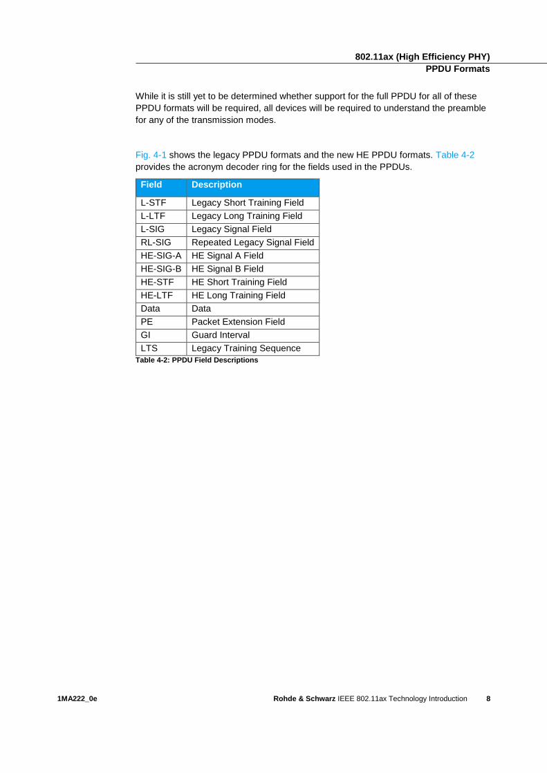
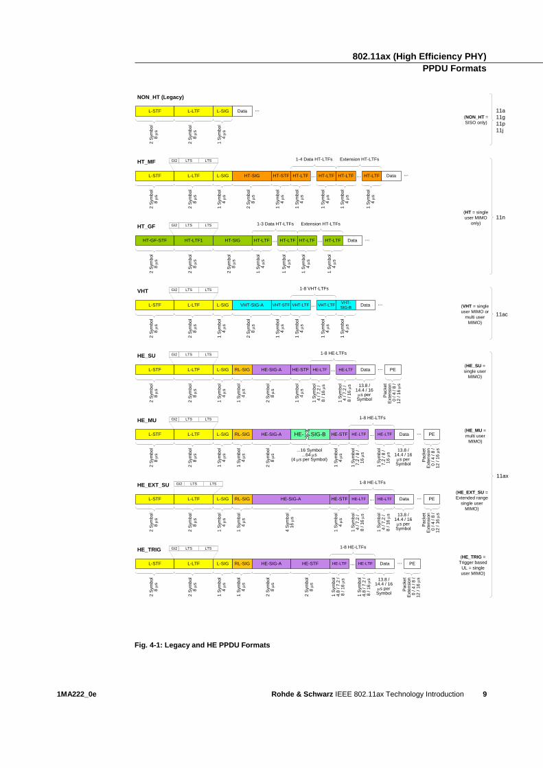
While it is still yet to be determined whether support for the full PPDU for all of these
PPDU formats will be required, all devices will be required to understand the preamble
for any of the transmission modes.
Fig. 4-1 shows the legacy PPDU formats and the new HE PPDU formats. Table 4-2
provides the acronym decoder ring for the fields used in the PPDUs.
Field Description
L-STF Legacy Short Training Field
L-LTF Legacy Long Training Field
L-SIG Legacy Signal Field
RL-SIG Repeated Legacy Signal Field
HE-SIG-A HE Signal A Field
HE-SIG-B HE Signal B Field
HE-STF HE Short Training Field
HE-LTF HE Long Training Field
Data Data
PE Packet Extension Field
GI Guard Interval
LTS Legacy Training Sequence
Table 4-2: PPDU Field Descriptions
802.11ax (High Efficiency PHY) PPDU Formats
1MA222_0e Rohde & Schwarz IEEE 802.11ax Technology Introduction
9
2 S
ym
bo
l8
s
NON_HT (Legacy)
L-STF
1 S
ym
bo
l4
s
L-SIG
2 S
ym
bo
l8
s
L-LTF
2 S
ym
bo
l8
s
HT_MF
L-STF
1 S
ym
bo
l4
s
L-SIG
2 S
ym
bo
l8
s
L-LTF
2 S
ym
bo
l8
s
HT-SIG
1 S
ym
bo
l4
s
HT-STF
1 S
ym
bo
l4
s
HT-LTF
Data ...
1 S
ym
bo
l4
s
HT-LTF...
1 S
ym
bo
l4
s
HT-LTF
1 S
ym
bo
l4
s
HT-LTF... Data ...
1-4 Data HT-LTFs Extension HT-LTFs
2 S
ym
bo
l8
s
HT_GF
HT-GF-STF
2 S
ym
bo
l8
s
HT-LTF1
2 S
ym
bo
l8
s
HT-SIG
1 S
ym
bo
l4
s
HT-LTF
1 S
ym
bo
l4
s
HT-LTF...
1 S
ym
bo
l4
s
HT-LTF
1 S
ym
bo
l4
s
HT-LTF... Data ...
1-3 Data HT-LTFs Extension HT-LTFs
2 S
ym
bo
l8
s
VHT
L-STF
1 S
ym
bo
l4
s
L-SIG
2 S
ym
bo
l8
s
L-LTF
2 S
ym
bo
l8
s
VHT-SIG-A
1 S
ym
bo
l4
s
VHT-STF
1 S
ym
bo
l4
s
VHT-LTF
1 S
ym
bo
l4
s
VHT-LTF...
1-8 VHT-LTFs
1 S
ym
bo
l4
s
VHT-
SIG-BData ...
11a
11g
11p
11j
11n
11ac
GI2 LTS LTS
GI2 LTS LTS
GI2 LTS LTS
11ax
(HT = single
user MIMO
only)
(NON_HT =
SISO only)
(VHT = single
user MIMO or
multi user
MIMO)
2 S
ym
bo
l8
s
HE_SU
L-STF
1 S
ym
bo
l4
s
L-SIG
2 S
ym
bo
l8
s
L-LTF
GI2 LTS LTS
1 S
ym
bo
l4
s
RL-SIG HE-SIG-A
2 S
ym
bo
l8
s
1 S
ym
bo
l4
s
HE-STF
1 S
ym
bo
l4
/ 7
.2 /
8 / 1
6
s
HE-LTF
1 S
ym
bo
l4
/ 7
.2 /
8 / 1
6
s
HE-LTF...
1-8 HE-LTFs
(HE_SU =
single user
MIMO)
Data ...
2 S
ym
bo
l8
s
HE_EXT_SU
L-STF
1 S
ym
bo
l4
s
L-SIG
2 S
ym
bo
l8
s
L-LTF
GI2 LTS LTS
1 S
ym
bo
l4
s
RL-SIG HE-SIG-A
4 S
ym
bo
l1
6
s
1 S
ym
bo
l4
s
HE-STF
1 S
ym
bo
l4
/ 7
.2 /
8 / 1
6
s
HE-LTF
1 S
ym
bo
l4
/ 7
.2 /
8 / 1
6
s
HE-LTF...
1-8 HE-LTFs
(HE_EXT_SU =
Extended range
single user
MIMO)
Data ...
2 S
ym
bo
l8
s
HE_MU
L-STF
1 S
ym
bo
l4
s
L-SIG
2 S
ym
bo
l8
s
L-LTF
GI2 LTS LTS
1 S
ym
bo
l4
s
RL-SIG HE-SIG-A
2 S
ym
bo
l8
s
HE- SIG-B
2 S
ym
bo
l8
s
HE_TRIG
L-STF
1 S
ym
bo
l4
s
L-SIG
2 S
ym
bo
l8
s
L-LTF
GI2 LTS LTS
1 S
ym
bo
l4
s
RL-SIG HE-SIG-A
2 S
ym
bo
l8
s
2 S
ym
bo
l8
s
HE-STF
1 S
ym
bo
l4
.8 / 7
.2 /
8 / 1
6
s
HE-LTF
1 S
ym
bo
l4
.8 / 7
.2 /
8 / 1
6
s
HE-LTF...
1-8 HE-LTFs
Data ...(HE_TRIG =
Trigger based
UL = single
user MIMO)
1 S
ym
bo
l4
s
HE-STF
1 S
ym
bo
l7
.2 / 8
/
16
s
HE-LTF
1 S
ym
bo
l7
.2 / 8
/
16
s
HE-LTF...
1-8 HE-LTFs
Data ... (HE_MU =
multi user
MIMO)
...16 Symbol...64 s
(4 s per Symbol)
PE
Pa
cke
tE
xte
nsio
n0
/ 4
/ 8
/
12
/ 1
6
s
PE
Pa
cke
tE
xte
nsio
n0
/ 4
/ 8
/
12
/ 1
6
s
PE
Pa
cke
tE
xte
nsio
n0
/ 4
/ 8
/
12
/ 1
6
s
PE
Pa
cke
tE
xte
nsio
n0
/ 4
/ 8
/
12
/ 1
6
s
13.8 / 14.4 / 16 s per Symbol
13.8 / 14.4 / 16 s per Symbol
13.8 / 14.4 / 16 s per Symbol
13.8 / 14.4 / 16 s per Symbol
Fig. 4-1: Legacy and HE PPDU Formats
802.11ax (High Efficiency PHY) From Single User to Multiple Users (MU)
1MA222_0e Rohde & Schwarz IEEE 802.11ax Technology Introduction
10
4.2 From Single User to Multiple Users (MU)
Legacy 802.11 technologies used OFDM (Orthogonal Frequency Division Multiplexing)
where transmissions are intended for a single user. 11ac added support for
transmission to multiple users in the downlink using MU-MIMO and 802.11ax adds
support for uplink MU-MIMO as well and also adds OFDMA for multiple users in the
uplink and downlink. Devices will be required to support OFDMA in the uplink and
downlink but it is likely that UL-MU-MIMO will not be required for initial 11ax devices.
Therefore, the focus of this section will be on OFDMA.
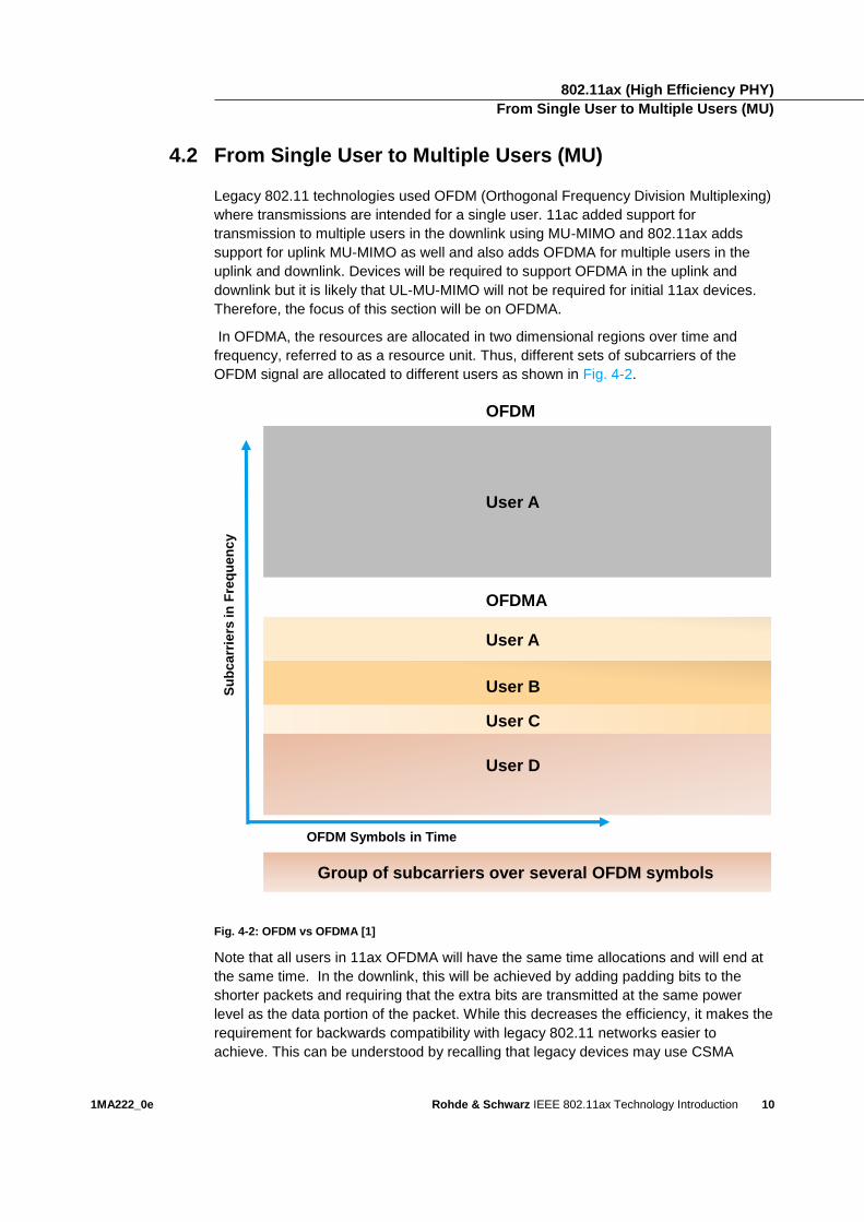
In OFDMA, the resources are allocated in two dimensional regions over time and
frequency, referred to as a resource unit. Thus, different sets of subcarriers of the
OFDM signal are allocated to different users as shown in Fig. 4-2.
OFDM
OFDMA
User A
User A
User B
User C
User D
Group of subcarriers over several OFDM symbols
Su
bc
arr
iers
in
Fre
qu
en
cy
OFDM Symbols in Time
Fig. 4-2: OFDM vs OFDMA [1]
Note that all users in 11ax OFDMA will have the same time allocations and will end at
the same time. In the downlink, this will be achieved by adding padding bits to the
shorter packets and requiring that the extra bits are transmitted at the same power
level as the data portion of the packet. While this decreases the efficiency, it makes the
requirement for backwards compatibility with legacy 802.11 networks easier to
achieve. This can be understood by recalling that legacy devices may use CSMA
802.11ax (High Efficiency PHY) From Single User to Multiple Users (MU)
1MA222_0e Rohde & Schwarz IEEE 802.11ax Technology Introduction
11
(Carrier Sense Multiple Access) to determine if the channel is free to use. If, for
example, one of the users had a longer packet than the other three users, the amount
of signal power that will be sensed when the remainder of the longer packet is
transmitted alone will be lower than when all users are transmitting together. In that
case, a legacy device may determine that the channel is available and begin
transmission. In addition to backwards compatibility, it may make synchronization of
the signals less complex and reduce the amount of overhead information required in
the preamble. An illustration of the DL OFDMA in time domain is shown in Fig. 4-3.
Fig. 4-3: DL-OFDMA padding example [6] *a=a-factor
In the MU uplink case, the AP will not know how much data the individual users have
to transmit. Therefore, the AP uses a control frame called a trigger frame to provide
information to the user to know how long it would like the uplink packet to be.
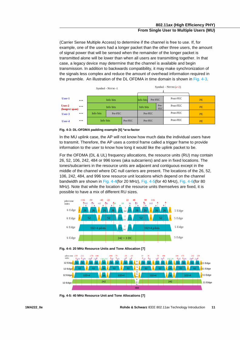
For the OFDMA (DL & UL) frequency allocations, the resource units (RU) may contain
26, 52, 106, 242, 484 or 996 tones (aka subcarriers) and are in fixed locations. The
tones/subcarriers in the resource units are adjacent and contiguous except in the
middle of the channel where DC null carriers are present. The locations of the 26, 52,
106, 242, 484, and 996 tone resource unit locations which depend on the channel
bandwidth are shown in Fig. 4-4(for 20 MHz), Fig. 4-5(for 40 MHz), Fig. 4-6(for 80
MHz). Note that while the location of the resource units themselves are fixed, it is
possible to have a mix of different RU sizes.
Fig. 4-4: 20 MHz Resource Units and Tone Allocation [7]
Fig. 4-5: 40 MHz Resource Unit and Tone Allocations [7]
User-1 …
Symbol - NSYM -1Symbol – NSYM (a=2)
User-2
(longest span)
Info bits Info bits Pre-FECPost-FEC
PE
Info bits Info bitsPre-
FECPE…
User-3 Info bits Pre-FEC PE… Pre-FEC
User-4 Info bits Pre-FEC PE… Pre-FEC
Post-FEC
Post-FEC
Post-FEC
484
12 Edge
12 Edge
12 Edge
12 Edge
11 Edge
11 Edge
11 Edge
11 Edge
5
DC
5
DC
5
DC
5
DC
242
26
26
26 102+4
26
52
26 1
1
26
52
261 2
1 2
1 1102+4
26
52
26 1
1
26
52
261 2
1 2
1 1
242
26
26
26 102+4
26
52
26 1
1
26
52
261 2
1 2
1 1102+4
26
52
26 1
1
26
52
261 2
1 2
1 1
-238 -212 -170 -144 -104 -78 -36 -10pilots tone
index -224 -198 -184 -158 -130 -116 -90 -64 -50 -24
10 36 78 104 144 170 212 238
24 50 64 90 116 130 158 184 198 224
7 DC
26 26 26 26 26 26 26
52 52 52 52
26
242 + 3 DC
102+4 pilots 102+4 pilots
1 1 1 1
13 1 1 1 1 13
13 13
5 Edge
5 Edge
5 Edge
5 Edge
6 Edge
6 Edge
6 Edge
6 Edge
7 DC
13 13 7
DC
-116 -90 -48 -22 22 48 90 116 -102 -76 -62 -36 -10 10 36 62 76 102
pilot tone
index
802.11ax (High Efficiency PHY) From Single User to Multiple Users (MU)
1MA222_0e Rohde & Schwarz IEEE 802.11ax Technology Introduction
12
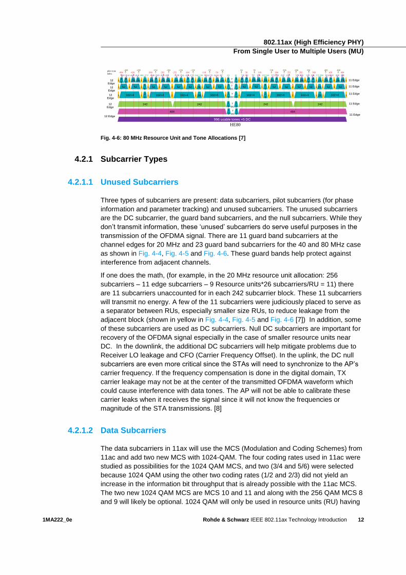
Fig. 4-6: 80 MHz Resource Unit and Tone Allocations [7]
4.2.1 Subcarrier Types
4.2.1.1 Unused Subcarriers
Three types of subcarriers are present: data subcarriers, pilot subcarriers (for phase
information and parameter tracking) and unused subcarriers. The unused subcarriers
are the DC subcarrier, the guard band subcarriers, and the null subcarriers. While they
don’t transmit information, these ‘unused’ subcarriers do serve useful purposes in the
transmission of the OFDMA signal. There are 11 guard band subcarriers at the
channel edges for 20 MHz and 23 guard band subcarriers for the 40 and 80 MHz case
as shown in Fig. 4-4, Fig. 4-5 and Fig. 4-6. These guard bands help protect against
interference from adjacent channels.
If one does the math, (for example, in the 20 MHz resource unit allocation: 256
subcarriers – 11 edge subcarriers – 9 Resource units*26 subcarriers/RU = 11) there
are 11 subcarriers unaccounted for in each 242 subcarrier block. These 11 subcarriers
will transmit no energy. A few of the 11 subcarriers were judiciously placed to serve as
a separator between RUs, especially smaller size RUs, to reduce leakage from the
adjacent block (shown in yellow in Fig. 4-4, Fig. 4-5 and Fig. 4-6 [7]) In addition, some
of these subcarriers are used as DC subcarriers. Null DC subcarriers are important for
recovery of the OFDMA signal especially in the case of smaller resource units near
DC. In the downlink, the additional DC subcarriers will help mitigate problems due to
Receiver LO leakage and CFO (Carrier Frequency Offset). In the uplink, the DC null
subcarriers are even more critical since the STAs will need to synchronize to the AP’s
carrier frequency. If the frequency compensation is done in the digital domain, TX
carrier leakage may not be at the center of the transmitted OFDMA waveform which
could cause interference with data tones. The AP will not be able to calibrate these
carrier leaks when it receives the signal since it will not know the frequencies or
magnitude of the STA transmissions. [8]
4.2.1.2 Data Subcarriers
The data subcarriers in 11ax will use the MCS (Modulation and Coding Schemes) from
11ac and add two new MCS with 1024-QAM. The four coding rates used in 11ac were
studied as possibilities for the 1024 QAM MCS, and two (3/4 and 5/6) were selected
because 1024 QAM using the other two coding rates (1/2 and 2/3) did not yield an
increase in the information bit throughput that is already possible with the 11ac MCS.
The two new 1024 QAM MCS are MCS 10 and 11 and along with the 256 QAM MCS 8
and 9 will likely be optional. 1024 QAM will only be used in resource units (RU) having
484
12 Edge
484
HE80
12 Edge
12 Edge
12 Edge
12 Edge
1
3
1
31
3
1
3
1
3
1
3
1
31
3
11 Edge
11 Edge
11 Edge
11 Edge
11 Edge
7
DC
7
DC
7
DC
7
DC
996 usable tones +5 DC
242 242
26 26
52
102+4 102+4
2
2
26
52
2
626
52
26
102+4 102+4
26
2
6
2
626
2
6
2
6
52
1
1
26 126
52
2
12
1 1 1
26 262
52
1
12
2
6226
52
1
21
26
26
2
6
2
62
52
1
12
1
1
11 2 1
242 242
26 26
52
102+4 102+4
2
2
26
52
2
626
52
26
102+4 102+4
26
2
6
2
626
2
6
2
6
52
1
1
26 126
52
2
12
1 1 1
26 262
52
1
12
2
6226
52
1
21
26
26
2
6
2
62
52
1
12
1
1
11 2 1
pilot tone
index-494 -426 -360 -292 -252 -184 -118 -50
-468 -400 -334 -266 -226 -158 -92 -24
-480 -454 -440 -414 -386 -372 -346 -320 -306 -280 -238 -212 -198 -172 -144 -130 -104 -78 -64 -38 -10
24 92 158 226 266 334 400 468
10 38 64 78 104 130 144 172 198 212 238 280 306 320 346 372 386 414 440 454 480
50 118 184 252 292 360 426 494
1
31
37
DC
802.11ax (High Efficiency PHY) From Single User to Multiple Users (MU)
1MA222_0e Rohde & Schwarz IEEE 802.11ax Technology Introduction
13
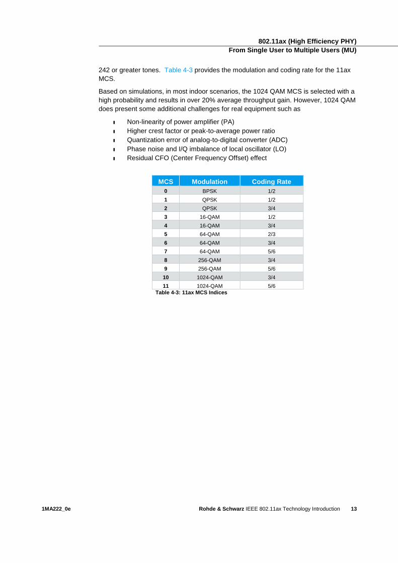
242 or greater tones. Table 4-3 provides the modulation and coding rate for the 11ax
MCS.
Based on simulations, in most indoor scenarios, the 1024 QAM MCS is selected with a
high probability and results in over 20% average throughput gain. However, 1024 QAM
does present some additional challenges for real equipment such as
ı Non-linearity of power amplifier (PA)
ı Higher crest factor or peak-to-average power ratio
ı Quantization error of analog-to-digital converter (ADC)
ı Phase noise and I/Q imbalance of local oscillator (LO)
ı Residual CFO (Center Frequency Offset) effect
MCS Modulation Coding Rate
0 BPSK 1/2
1 QPSK 1/2
2 QPSK 3/4
3 16-QAM 1/2
4 16-QAM 3/4
5 64-QAM 2/3
6 64-QAM 3/4
7 64-QAM 5/6
8 256-QAM 3/4
9 256-QAM 5/6
10 1024-QAM 3/4
11 1024-QAM 5/6
Table 4-3: 11ax MCS Indices
802.11ax (High Efficiency PHY) From Single User to Multiple Users (MU)
1MA222_0e Rohde & Schwarz IEEE 802.11ax Technology Introduction
14
4.2.1.3 Pilot Subcarriers
Pilots are subcarriers that transmit a known signal that are used by the OFDM
demodulator to compensate for frequency errors, etc., and are critical to proper
demodulation of the received signal. They are an important part of the transmission.
Since they transmit no data information, the number of pilots should be kept at a
minimum while still having enough to properly demodulate the signal. Because 11ax
supports several bandwidths and resource unit sizes, the 11ax group needed to
carefully consider the best location for the pilots in order to keep the
implementation/computational requirements as simple as possible. To achieve that
goal, 11ax will use pilots that are fixed and aligned in location across all of the resource
allocation sizes.
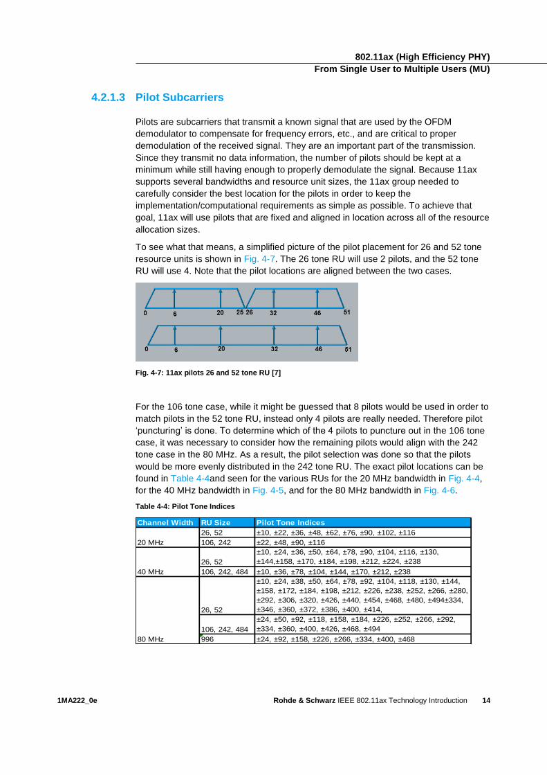
To see what that means, a simplified picture of the pilot placement for 26 and 52 tone
resource units is shown in Fig. 4-7. The 26 tone RU will use 2 pilots, and the 52 tone
RU will use 4. Note that the pilot locations are aligned between the two cases.
Fig. 4-7: 11ax pilots 26 and 52 tone RU [7]
For the 106 tone case, while it might be guessed that 8 pilots would be used in order to
match pilots in the 52 tone RU, instead only 4 pilots are really needed. Therefore pilot
‘puncturing’ is done. To determine which of the 4 pilots to puncture out in the 106 tone
case, it was necessary to consider how the remaining pilots would align with the 242
tone case in the 80 MHz. As a result, the pilot selection was done so that the pilots
would be more evenly distributed in the 242 tone RU. The exact pilot locations can be
found in Table 4-4and seen for the various RUs for the 20 MHz bandwidth in Fig. 4-4,
for the 40 MHz bandwidth in Fig. 4-5, and for the 80 MHz bandwidth in Fig. 4-6.
Table 4-4: Pilot Tone Indices
Channel Width RU Size Pilot Tone Indices
26, 52 ±10, ±22, ±36, ±48, ±62, ±76, ±90, ±102, ±116
106, 242 ±22, ±48, ±90, ±116
26, 52
±10, ±24, ±36, ±50, ±64, ±78, ±90, ±104, ±116, ±130,
±144,±158, ±170, ±184, ±198, ±212, ±224, ±238
106, 242, 484 ±10, ±36, ±78, ±104, ±144, ±170, ±212, ±238
26, 52
±10, ±24, ±38, ±50, ±64, ±78, ±92, ±104, ±118, ±130, ±144,
±158, ±172, ±184, ±198, ±212, ±226, ±238, ±252, ±266, ±280,
±292, ±306, ±320, ±426, ±440, ±454, ±468, ±480, ±494±334,
±346, ±360, ±372, ±386, ±400, ±414,
106, 242, 484
±24, ±50, ±92, ±118, ±158, ±184, ±226, ±252, ±266, ±292,
±334, ±360, ±400, ±426, ±468, ±494
996 ±24, ±92, ±158, ±226, ±266, ±334, ±400, ±468
20 MHz
40 MHz
80 MHz
802.11ax (High Efficiency PHY) From Single User to Multiple Users (MU)
1MA222_0e Rohde & Schwarz IEEE 802.11ax Technology Introduction
15
4.2.2 OFDMA Downlink Resource Unit Assignments
Since multiple users are intended recipients in the OFDMA downlink, the AP needs to
tell the STAs which resource unit belong to them. In 802.11ax, the AP uses the HE-
SIG-B field in the HE_MU_PPDU to do this. The SIG-B field is only found in the
downlink HE-MU-PPDU (see Fig. 4-1).
The SIG-B contains two fields:
ı Common field, where RU allocation info is included (See Table 4-5 for
complete details of common field. Note the section for CRC calculation is
found in the 802.11ax draft.)
ı User-specific field, where per-STA info belongs to (e.g. STA-ID, MCS, Nsts )
It is encoded on a per-20 MHz basis using BCC and is sent on the STA’s preferred
band so that the STA’s signaling information (e.g. HE-SIG-B) is sent on the same band
as the payload [9].
Table 4-5: SIG-B Common Info Field [10]
Field # of bits Description
RU Allocation 𝑁 × 8 Indicates the RU arrangement in frequency domain. It also indicates
number of user fields in each RU. For RUs of size greater than or
equal to 106-tones that support MU-MIMO, it indicates the number
of users multiplexed using MU-MIMO.
𝑁 = 1 for 20 MHz and 40 MHz HE MU PPDU
𝑁 = 2 for 80 MHz HE MU PPDU
𝑁 = 4 for 160/80+80 MHz HE MU PPDU
Center 26-tone RU 1 This field is present only for full bandwidth 80 MHz and 160/80+80
MHz.
For full bandwidth 80 MHz
Set to 1 to indicate that Center 26 -tone RU is allocated in the
Common Block fields of both SIGB content channels with same
value. Set to 0, otherwise.
For full bandwidth 160/80+80 MHz
Set to 1 to indicate that Center 26 -tone RU is allocated for one
individual 80 MHz in Common Block fields of both SIGB content
channels. Set to 0, otherwise.
CRC 4 See CRC computation (Section 26.3.9.7.3 in 802.11ax draft
v0.4)
Tail 6 Used to terminate the trellis of the convolutional decoder. Set to 0.
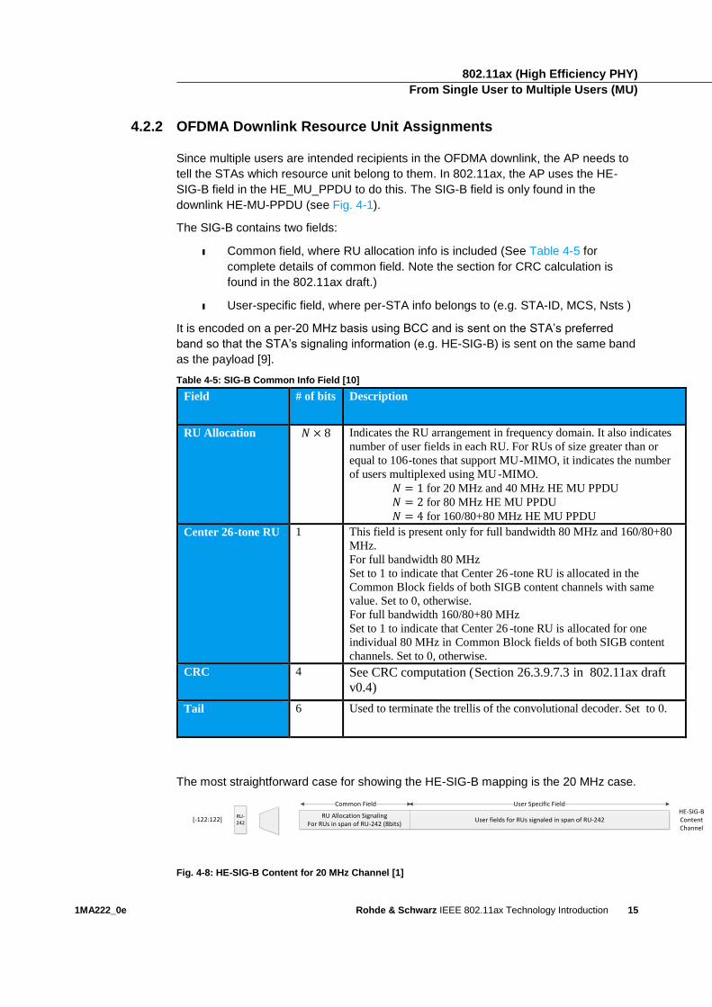
The most straightforward case for showing the HE-SIG-B mapping is the 20 MHz case.
RU Allocation Signaling For RUs in span of RU-242 (8bits)
User fields for RUs signaled in span of RU-242HE-SIG-B Content Channel
RU-242
[-122:122]
Common Field User Specific Field
Fig. 4-8: HE-SIG-B Content for 20 MHz Channel [1]
802.11ax (High Efficiency PHY) From Single User to Multiple Users (MU)
1MA222_0e Rohde & Schwarz IEEE 802.11ax Technology Introduction
16
As shown in Fig. 4-8 for the 20 MHz case, the common field which contains 8 bits for
the RU allocation signaling followed by the user specific field which contains the user
specific information. Table 4-7 shows the values of the 8 bits and the corresponding
allocation. For example, if there are 9 users each being assigned 26 tone RUs, the
common field would contain 00000000. Another example, if there are 6 users with 1
user allocated 106 tone RU and the remaining 5 users assigned 26 tone RU each, then
the common field would contain 01000000. In 802.11ax, a user can be assigned to
only one RU.
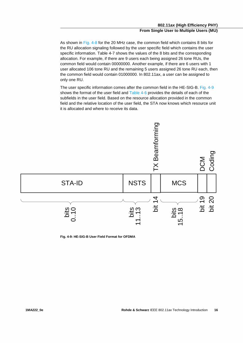
The user specific information comes after the common field in the HE-SIG-B. Fig. 4-9
shows the format of the user field and Table 4-6 provides the details of each of the
subfields in the user field. Based on the resource allocation provided in the common
field and the relative location of the user field, the STA now knows which resource unit
it is allocated and where to receive its data.
Fig. 4-9: HE-SIG-B User Field Format for OFDMA
STA-ID
bits
0..1
0
NSTS
bits
11
..1
3 bit 1
4T
X B
ea
mfo
rmin
g
MCS
bits
15
..1
8 bit 1
9D
CM
bit 2
0C
od
ing
802.11ax (High Efficiency PHY) From Single User to Multiple Users (MU)
1MA222_0e Rohde & Schwarz IEEE 802.11ax Technology Introduction
17
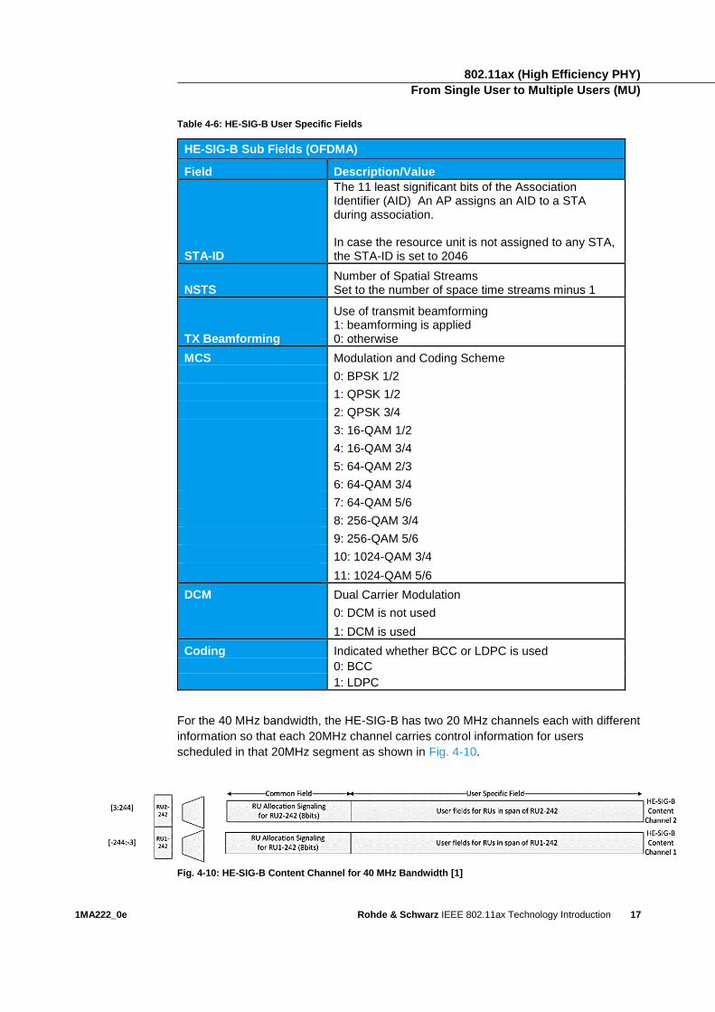
Table 4-6: HE-SIG-B User Specific Fields
HE-SIG-B Sub Fields (OFDMA)
Field Description/Value
STA-ID
The 11 least significant bits of the Association Identifier (AID) An AP assigns an AID to a STA during association. In case the resource unit is not assigned to any STA, the STA-ID is set to 2046
NSTS Number of Spatial Streams Set to the number of space time streams minus 1
TX Beamforming
Use of transmit beamforming 1: beamforming is applied 0: otherwise
MCS Modulation and Coding Scheme
0: BPSK 1/2
1: QPSK 1/2
2: QPSK 3/4
3: 16-QAM 1/2
4: 16-QAM 3/4
5: 64-QAM 2/3
6: 64-QAM 3/4
7: 64-QAM 5/6
8: 256-QAM 3/4
9: 256-QAM 5/6
10: 1024-QAM 3/4
11: 1024-QAM 5/6
DCM Dual Carrier Modulation
0: DCM is not used
1: DCM is used
Coding Indicated whether BCC or LDPC is used
0: BCC
1: LDPC
For the 40 MHz bandwidth, the HE-SIG-B has two 20 MHz channels each with different
information so that each 20MHz channel carries control information for users
scheduled in that 20MHz segment as shown in Fig. 4-10.
Fig. 4-10: HE-SIG-B Content Channel for 40 MHz Bandwidth [1]
802.11ax (High Efficiency PHY) From Single User to Multiple Users (MU)
1MA222_0e Rohde & Schwarz IEEE 802.11ax Technology Introduction
18
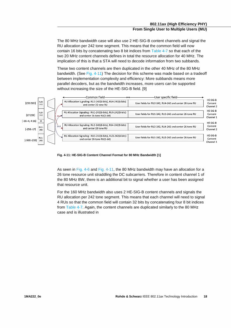
The 80 MHz bandwidth case will also use 2 HE-SIG-B content channels and signal the
RU allocation per 242 tone segment. This means that the common field will now
contain 16 bits by concatenating two 8 bit indices from Table 4-7 so that each of the
two 20 MHz content channels defines in total the resource allocation for 40 MHz. The
implication of this is that a STA will need to decode information from two subbands.
These two content channels are then duplicated in the other 40 MHz of the 80 MHz
bandwidth. (See Fig. 4-11) The decision for this scheme was made based on a tradeoff
between implementation complexity and efficiency: More subbands means more
parallel decoders, but as the bandwidth increases, more users can be supported
without increasing the size of the HE-SIG-B field. [9]
Fig. 4-11: HE-SIG-B Content Channel Format for 80 MHz Bandwidth [1]
As seen in Fig. 4-6 and Fig. 4-11, the 80 MHz bandwidth may have an allocation for a
26 tone resource unit straddling the DC subcarriers. Therefore in content channel 1 of
the 80 MHz BW, there is an additional bit to signal whether a user has been assigned
that resource unit.
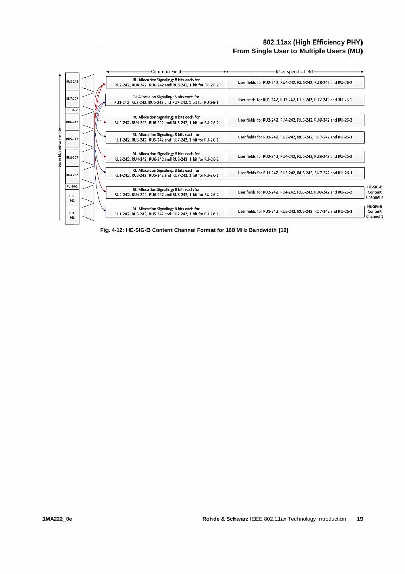
For the 160 MHz bandwidth also uses 2 HE-SIG-B content channels and signals the
RU allocation per 242 tone segment. This means that each channel will need to signal
4 RUs so that the common field will contain 32 bits by concatenating four 8 bit indices
from Table 4-7. Again, the content channels are duplicated similarly to the 80 MHz
case and is illustrated in
802.11ax (High Efficiency PHY) From Single User to Multiple Users (MU)
1MA222_0e Rohde & Schwarz IEEE 802.11ax Technology Introduction
19
Fig. 4-12: HE-SIG-B Content Channel Format for 160 MHz Bandwidth [10]

802.11ax (High Efficiency PHY) From Single User to Multiple Users (MU)
1MA222_0e Rohde & Schwarz IEEE 802.11ax Technology Introduction
20
8 bits indices (b7 b6 b5 b4 b3 b2 b1 b0)
#1 #2 #3 #4 #5 #6 #7 #8 #9
00000000 26 26 26 26 26 26 26 26 26
00000001 26 26 26 26 26 26 26 52
00000010 26 26 26 26 26 52 26 26
00000011 26 26 26 26 26 52 52
00000100 26 26 52 26 26 26 26 26
00000101 26 26 52 26 26 26 52
00000110 26 26 52 26 52 26 26
00000111 26 26 52 26 52 52
00001000 52 26 26 26 26 26 26 26
00001001 52 26 26 26 26 26 52
00001010 52 26 26 26 52 26 26
00001011 52 26 26 26 52 52
00001100 52 52 26 26 26 26 26
00001101 52 52 26 26 26 52
00001110 52 52 26 52 26 26
00001111 52 52 26 52 52
00010000 52 52 - 106
00011000 106 - 52 52
00100000 26 26 26 26 26 106
00101000 26 26 52 26 106
00110000 52 26 26 26 106
00111000 52 52 26 106
01000000 106 26 26 26 26 26
01001000 106 26 26 26 52
01010000 106 26 52 26 26
01011000 106 26 52 52
01100000 106 - 106
01110000 52 52 - 52 52
01110001 242-tone RU empty
01110010 484-tone RU with zero HE-SIG-B User Specific field in the corresponding
HE-SIG-B Content Channel
01110011 996-tone RU with zero HE-SIG-B User Specific field in the corresponding
HE-SIG-B Content Channel
011101x1x0 Definition TBD
011111x1x0 Definition TBD
10000000 106 26 106
11000000 242
11001000 484
11010000 996
11011000 2*996
111x4x3x2x1x0 Definition TBD
Table 4-7: 8 bit indices for RU allocation per 242 tone for OFDMA
802.11ax (High Efficiency PHY) From Single User to Multiple Users (MU)
1MA222_0e Rohde & Schwarz IEEE 802.11ax Technology Introduction
21
4.2.3 OFDMA Uplink Resource Unit Assignments
To solicit uplink multi-user transmissions, the 802.11ax AP sends a control frame that
is called a trigger frame. This frame solicits and allocates resources for UL MU
transmissions a SIFS (Short Interframe Space) after the PPDU that carries the trigger
frame in the downlink. The SIFS is the shortest interframe space between
transmissions from different STAs defined in the 802.11 standard. This is enough time
for the responding STAs to prepare the data to send to the AP, but it is too short for
other STAs to attempt to use the channel since they would need to wait a longer time
for the channel to be considered idle to begin transmission.
Although the trigger frame is a new control frame added to support 11ax, it is not
required to transmit this frame using an HE frame format. In fact, transmitting the
control frame using a legacy frame format may be beneficial since this 1. provides the
legacy stations info on the TXOP time, etc., and 2. uses less overhead than the HE
frame format.
Details of the format of this frame are still not fixed. However, the frame will contain a
field called ‘common info’ which provides, as the name implies, information that is the
same for all responding STAs. For information that is specific to a particular STA, the
‘user info’ field is used.
Contents of Trigger Frame Common Field
Information contained in the common field of the trigger frame includes:
ı Length: This is the length in microseconds of the expected uplink packet.
ı Number of HE-LTF Symbols: number of long training fields the responding
UL MU STAs should use.
ı HE- LTF symbol length: The length of the HE-LTF including GI. Possible
values are 4.8 µs, 7.2 µs, 8 µs, and 16 µs.
ı Bandwidth: Specifies the bandwidth for the trigger based uplink PPDU
Contents of Trigger Frame User Field
Information that is unique for a responding UL MU STA is contained within the user
field of the trigger fame. The user field starts with a STA AID to indicate the intended
STA and is followed by user specific information such as:
ı RU Allocation: Indicates the Resources Units allocated for the STA
ı Coding Type: Indicates whether BCC or LDPC coding is used
ı MCS: Indicates the MCS the STA should use in the trigger based PPDU
802.11ax (High Efficiency PHY) From Single User to Multiple Users (MU)
1MA222_0e Rohde & Schwarz IEEE 802.11ax Technology Introduction
22
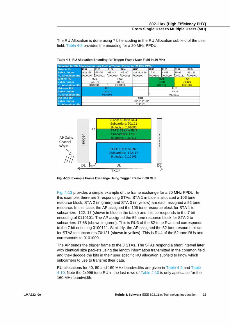
The RU Allocation is done using 7 bit encoding in the RU Allocation subfield of the user
field. Table 4-8 provides the encoding for a 20 MHz PPDU.
Table 4-8: RU Allocation Encoding for Trigger Frame User Field in 20 MHz
Encoding for RU Allocation in User Field of Trigger Frame for 20 MHz PPDU
26-tone RU RU1 RU2 RU3 RU4 RU5 RU6 RU7 RU8 RU9
Subcxr index -121:-96 -95:-70 -68:-43 -42:-17 -16:-4, 4:16 17:42 43:68 70:95 96:121
RU Allocation bits 0000000 0000001 0000010 0000011 0000100 0000101 0000110 0000111 0001000
52-tone RU
Subcxr index
RU Allocation bits
106-tone RU
Subcxr index
RU Allocation bits
242-tone RU
Subcxr index
RU Allocation bits
RU1 RU2 RU3 RU4
-121:-70 -68:-17 17:68 70:121
0100101 0100110 0100111 0101000
RU1 RU2
0111101
-122:-17 17:122
0110101 0110110
RU1
-122:-2, 2:122
TXOP
AP Gains
Channel
Access
DLULDL
Trig
ge
r
SIFS
STA1: 106 tone RU1
Subcarriers: -122:-17
Bit Index: 0110101
STA2: 52 tone RU3
Subcarriers: 17:68
Bit Index: 0100111
STA3: 52 tone RU4
Subcarriers: 70:121
Bit Index: 0101000
A
c
k/
B
A
Fig. 4-13: Example Frame Exchange Using Trigger Frame in 20 MHz
Fig. 4-13 provides a simple example of the frame exchange for a 20 MHz PPDU. In
this example, there are 3 responding STAs. STA 1 in blue is allocated a 106 tone
resource block; STA 2 (in green) and STA 3 (in yellow) are each assigned a 52 tone
resource. In this case, the AP assigned the 106 tone resource block for STA 1 to
subcarriers -122:-17 (shown in blue in the table) and this corresponds to the 7 bit
encoding of 0110101. The AP assigned the 52 tone resource block for STA 2 to
subcarriers 17:68 (shown in green). This is RU3 of the 52-tone RUs and corresponds
to the 7 bit encoding 0100111. Similarly, the AP assigned the 52 tone resource block
for STA3 to subcarriers 70:121 (shown in yellow). This is RU4 of the 52 tone RUs and
corresponds to 0101000.
The AP sends the trigger frame to the 3 STAs. The STAs respond a short interval later
with identical size packets using the length information transmitted in the common field
and they decode the bits in their user specific RU allocation subfield to know which
subcarriers to use to transmit their data.
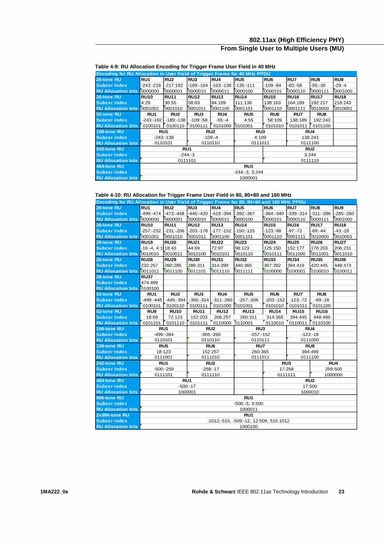
RU allocations for 40, 80 and 160 MHz bandwidths are given in Table 4-9 and Table
4-10. Note the 2x996 tone RU in the last rows of Table 4-10 is only applicable for the
160 MHz bandwidth.
802.11ax (High Efficiency PHY) From Single User to Multiple Users (MU)
1MA222_0e Rohde & Schwarz IEEE 802.11ax Technology Introduction
23
Table 4-9: RU Allocation Encoding for Trigger Frame User Field in 40 MHz
Encoding for RU Allocation in User Field of Trigger Frame for 40 MHz PPDU
26-tone RU RU1 RU2 RU3 RU4 RU5 RU6 RU7 RU8 RU9
Subcxr index -243:-218 -217:192 -189:-164 -163:-138 -135:-111 -109:-84 -83:-58 -55:-30 -29:-4
RU Allocation bits 0000000 0000001 0000010 0000011 0000100 0000101 0000110 0000111 0001000
26-tone RU RU10 RU11 RU12 RU13 RU14 RU15 RU16 RU17 RU18
Subcxr index 4:29 30:55 58:83 84:109 111:136 138:163 164:189 192:217 218:243
RU Allocation bits 0001001 0001010 0001011 0001100 0001101 0001110 0001111 0010000 0010001
52-tone RU RU1 RU2 RU3 RU4 RU5 RU6 RU7 RU8
Subcxr index -243:-192 -189:-138 -109:-58 -55:-4 4:55 58:109 138:189 192:243
RU Allocation bits 0100101 0100110 0100111 0101000 0101001 0101010 0101011 0101100
106-tone RU
Subcxr index
RU Allocation bits
242-tone RU
Subcxr index
RU Allocation bits
484-tone RU
Subcxr index
RU Allocation bits
RU2
0110101 0110110 0111011 0111100
-244:-3, 3:244
1000001
RU1 RU2 RU3 RU4
-243:-138 -109:-4 4:109 138:243
-244:-3 3:244
0111101 0111110
RU1
RU1
Table 4-10: RU Allocation for Trigger Frame User Field in 80, 80+80 and 160 MHz
Encoding for RU Allocation in User Field of Trigger Frame for 80, 80+80 and 160 MHz PPDU
26-tone RU RU1 RU2 RU3 RU4 RU5 RU6 RU7 RU8 RU9
Subcxr index -499:-474 -473:-448 -445:-420 -419:-394 -392:-367 -364:-340 -339:-314 -311:-286 -285:-260
RU Allocation bits 0000000 0000001 0000010 0000011 0000100 0000101 0000110 0000111 0001000
26-tone RU RU10 RU11 RU12 RU13 RU14 RU15 RU16 RU17 RU18
Subcxr index -257:-232 -231:-206 -203:-178 -177:-152 -150:-125 -123:-98 -97:-72 -69:-44 -43:-18
RU Allocation bits 0001001 0001010 0001011 0001100 0001101 0001110 0001111 0010000 0010001
26-tone RU RU19 RU20 RU21 RU22 RU23 RU24 RU25 RU26 RU27
Subcxr index -16:-4, 4:1618:43 44:69 72:97 98:123 125:150 152:177 178:203 206:231
RU Allocation bits 0010010 0010011 0010100 0010101 0010110 0010111 0011000 0011001 0011010
26-tone RU RU28 RU29 RU30 RU31 RU32 RU33 RU34 RU35 RU36
Subcxr index 232:257 260:285 286:311 314:399 340:365 367:392 394:419 420:445 448:473
RU Allocation bits 0011011 0011100 0011101 0011110 0011111 0100000 0100001 0100010 0100011
26-tone RU RU37
Subcxr index 474:499
RU Allocation bits 0100100
52-tone RU RU1 RU2 RU3 RU4 RU5 RU6 RU7 RU8
Subcxr index -499:-448 -445:-394 -365:-314 -311:-260 -257:-206 -203:-152 -123:-72 -69:-18
RU Allocation bits 0100101 0100110 0100111 0101000 0101001 0101010 0101011 0101100
52-tone RU RU9 RU10 RU11 RU12 RU13 RU14 RU15 RU16
Subcxr index 18:69 72:123 152:203 206:257 260:311 314:365 394:445 448:499
RU Allocation bits 0101101 0101110 0101111 0110000 0110001 0110010 0110011 0110100
106-tone RU
Subcxr index
RU Allocation bits
106-tone RU
Subcxr index
RU Allocation bits
242-tone RU
Subcxr index
RU Allocation bits
484-tone RU
Subcxr index
RU Allocation bits
996-tone RU
Subcxr index
RU Allocation bits
2x996-tone RU
Subcxr index
RU Allocation bits 1000100
RU1
-500:-3, 3:500
1000011
RU1
-1012:-515, -509:-12, 12:509, 515:1012
-500:-17
1000001
RU2
17:500
1000010
RU5 RU6 RU7 RU8
18:123 152:257 260:365 394:499
0111001 0111010 0111011 0111100
RU1
259:500
0111111 1000000
RU1
0110101 0110110 0110111 0111000
RU2 RU3 RU4
-500:-259
0111101
-258:-17
0111110
17:258
RU1 RU2 RU3 RU4
-499:-394 -365:-260 -257:-152 -123:-18
802.11ax Measurements 802.11ax Transmitter Specification
1MA222_0e Rohde & Schwarz IEEE 802.11ax Technology Introduction
24
5 802.11ax Measurements
802.11ax will likely re-use many of the specifications from the 802.11ac amendment.
Differences from the 802.11ac specification are given in this section. Devices that
support the 802.11ax trigger-based PPDU have many requirements that need to be
met in order for the uplink MU transmissions to behave properly and these
requirements are included here as well. (For application notes and information for
testing 802.11ac, please see: https://www.rohde-
schwarz.com/us/search/applications_63466.html?term=802.11ac&x=0&y=0 )
5.1 802.11ax Transmitter Specification
5.1.1 Transmit Spectrum Mask
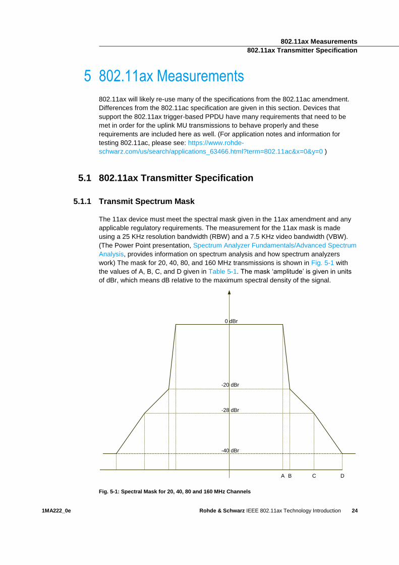
The 11ax device must meet the spectral mask given in the 11ax amendment and any
applicable regulatory requirements. The measurement for the 11ax mask is made
using a 25 KHz resolution bandwidth (RBW) and a 7.5 KHz video bandwidth (VBW).
(The Power Point presentation, Spectrum Analyzer Fundamentals/Advanced Spectrum
Analysis, provides information on spectrum analysis and how spectrum analyzers
work) The mask for 20, 40, 80, and 160 MHz transmissions is shown in Fig. 5-1 with
the values of A, B, C, and D given in Table 5-1. The mask ‘amplitude’ is given in units
of dBr, which means dB relative to the maximum spectral density of the signal.
0 dBr
-20 dBr
-28 dBr
-40 dBr
A B C D
Fig. 5-1: Spectral Mask for 20, 40, 80 and 160 MHz Channels
802.11ax Measurements 802.11ax Transmitter Specification
1MA222_0e Rohde & Schwarz IEEE 802.11ax Technology Introduction
25
Table 5-1: Frequency Offsets for Spectral Mask Requirement
Channel Size A B C D
20 MHz 9.75 MHz 10.25 MHz 20 MHz 30 MHz
40 MHz 19.5 MHz 20.5 MHz 40 MHz 60 MHz
80 MHz 39.5 MHz 40.5 MHz 80 MHz 120 MHz
160 MHz 79.5 MHz 80.5 MHz 160 MHz 240 MHz
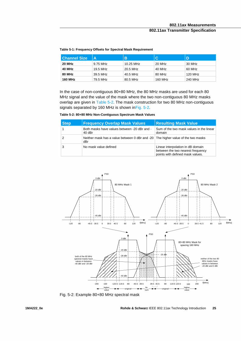
In the case of non-contiguous 80+80 MHz, the 80 MHz masks are used for each 80
MHz signal and the value of the mask where the two non-contiguous 80 MHz masks
overlap are given in Table 5-2. The mask construction for two 80 MHz non-contiguous
signals separated by 160 MHz is shown inFig. 5-2.
Table 5-2: 80+80 MHz Non-Contiguous Spectrum Mask Values
Step Frequency Overlap Mask Values Resulting Mask Value
1 Both masks have values between -20 dBr and -40 dBr
Sum of the two mask values in the linear domain
2 Neither mask has a value between 0 dBr and -20 dBr
The higher value of the two masks
3 No mask value defined Linear interpolation in dB domain between the two nearest frequency points with defined mask values.
PSD
f[MHz]
0 dBr
-20 dBr
-28 dBr
-40 dBr
-120 -80 -40.5 -39.5 0 39.5 40.5 80 120
PSD
f[MHz]
0 dBr
-20 dBr
-28 dBr
-40 dBr
-120 -80 -40.5 -39.5 0 39.5 41.5 80 120
0 dBr
-20 dBr
-28 dBr
-40 dBr
f[MHz]
PSD
lin.
sumoriginal original
higher
value
higher
value
-25 dBr
80 MHz Mask 1 80 MHz Mask 2
80+80 MHz Mask for
spacing 160 MHz
-80 -40.5 -39.5-119.5-120.5-160-200 39.5 40.5 80 119.5 120.5 160 200
both of the 80 MHz
spectral masks have
values in between
-40 dBr and -20 dBr
neither of the two 80
MHz masks have
values in between
-20 dBr and 0 dBr
Fig. 5-2: Example 80+80 MHz spectral mask
802.11ax Measurements 802.11ax Transmitter Specification
1MA222_0e Rohde & Schwarz IEEE 802.11ax Technology Introduction
26
5.1.2 Spectral Flatness
Spectral flatness provides a way to measure whether the subcarriers have a similar
amount of power. This is done by determining the average energy of a range of
subcarriers and verifying that no individual subcarrier’s energy in that range deviates
by more than the value specified.
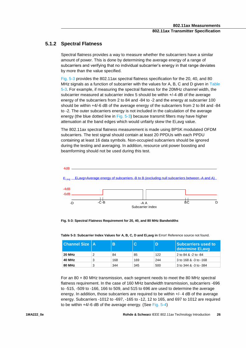
Fig. 5-3 provides the 802.11ax spectral flatness specification for the 20, 40, and 80
MHz signals as a function of subcarrier with the values for A, B, C and D given in Table
5-3. For example, if measuring the spectral flatness for the 20MHz channel width, the
subcarrier measured at subcarrier index 5 should be within +/-4 dB of the average
energy of the subcarriers from 2 to 84 and -84 to -2 and the energy at subcarrier 100
should be within +4/-6 dB of the average energy of the subcarriers from 2 to 84 and -84
to -2. The outer subcarriers energy is not included in the calculation of the average
energy (the blue dotted line in Fig. 5-3) because transmit filters may have higher
attenuation at the band edges which would unfairly skew the Ei,avg value.
The 802.11ax spectral flatness measurement is made using BPSK modulated OFDM
subcarriers. The test signal should contain at least 20 PPDUs with each PPDU
containing at least 16 data symbols. Non-occupied subcarriers should be ignored
during the testing and averaging. In addition, resource unit power boosting and
beamforming should not be used during this test.
Subcarrier index
4dB
-4dB
-6dB
A BC-A-B-D
Ei,avg
-C
Ei,avg=Average energy of subcarriers -B to B (excluding null subcarriers between -A and A)
D
Fig. 5-3: Spectral Flatness Requirement for 20, 40, and 80 MHz Bandwidths
Table 5-3: Subcarrier Index Values for A, B, C, D and Ei,avg in Error! Reference source not found.
Channel Size A B C D Subcarriers used to determine Ei,avg
20 MHz 2 84 85 122 2 to 84 & -2 to -84
40 MHz 3 168 169 244 3 to 168 & -3 to -168
80 MHz 3 344 345 500 3 to 344 & -3 to -384
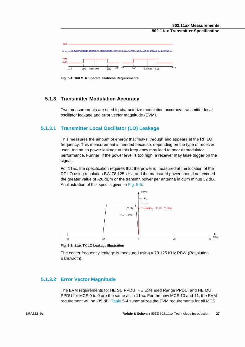
For an 80 + 80 MHz transmission, each segment needs to meet the 80 MHz spectral
flatness requirement. In the case of 160 MHz bandwidth transmission, subcarriers -696
to -515, -509 to -166, 166 to 509, and 515 to 696 are used to determine the average
energy. In addition, those subcarriers are required to be within +/- 4 dB of the average
energy. Subcarriers -1012 to -697, -165 to -12, 12 to 165, and 697 to 1012 are required
to be within +4/-6 dB of the average energy. (See Fig. 5-4)
802.11ax Measurements 802.11ax Transmitter Specification
1MA222_0e Rohde & Schwarz IEEE 802.11ax Technology Introduction
27
4dB
-4dB
-6dB
-509 -166-515-696-1012
Ei,avg Ei,avg=Average energy of subcarriers -696 to -515, -509 to -166, 166 to 509, & 515 to 696)
-12 515 69650916612 1012
Fig. 5-4: 160 MHz Spectral Flatness Requirements
5.1.3 Transmitter Modulation Accuracy
Two measurements are used to characterize modulation accuracy: transmitter local
oscillator leakage and error vector magnitude (EVM).
5.1.3.1 Transmitter Local Oscillator (LO) Leakage
This measures the amount of energy that ‘leaks’ through and appears at the RF LO
frequency. This measurement is needed because, depending on the type of receiver
used, too much power leakage at this frequency may lead to poor demodulator
performance. Further, if the power level is too high, a receiver may false trigger on the
signal.
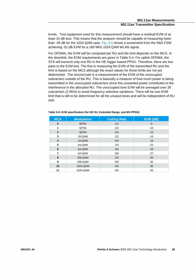
For 11ax, the specification requires that the power is measured at the location of the
RF LO using resolution BW 78.125 kHz, and the measured power should not exceed
the greater value of -20 dBm or the transmit power per antenna in dBm minus 32 dB.
An illustration of this spec is given in Fig. 5-5.
Fig. 5-5: 11ax TX LO Leakage illustration
The center frequency leakage is measured using a 78.125 KHz RBW (Resolution
Bandwidth).
5.1.3.2 Error Vector Magnitude
The EVM requirements for HE SU PPDU, HE Extended Range PPDU, and HE MU
PPDU for MCS 0 to 9 are the same as in 11ac. For the new MCS 10 and 11, the EVM
requirement will be -35 dB. Table 5-4 summarizes the EVM requirements for all MCS
Power
f[Bin]-28-56 0 5628
Ptot – 32 dB
Ptot
> 32 dB
-20 dB P < max(Ptot – 32 dB, -20 dBm)
802.11ax Measurements 802.11ax Transmitter Specification
1MA222_0e Rohde & Schwarz IEEE 802.11ax Technology Introduction
28
levels. Test equipment used for this measurement should have a residual EVM of at
least 10 dB less. This means that the analyzer should be capable of measuring lower
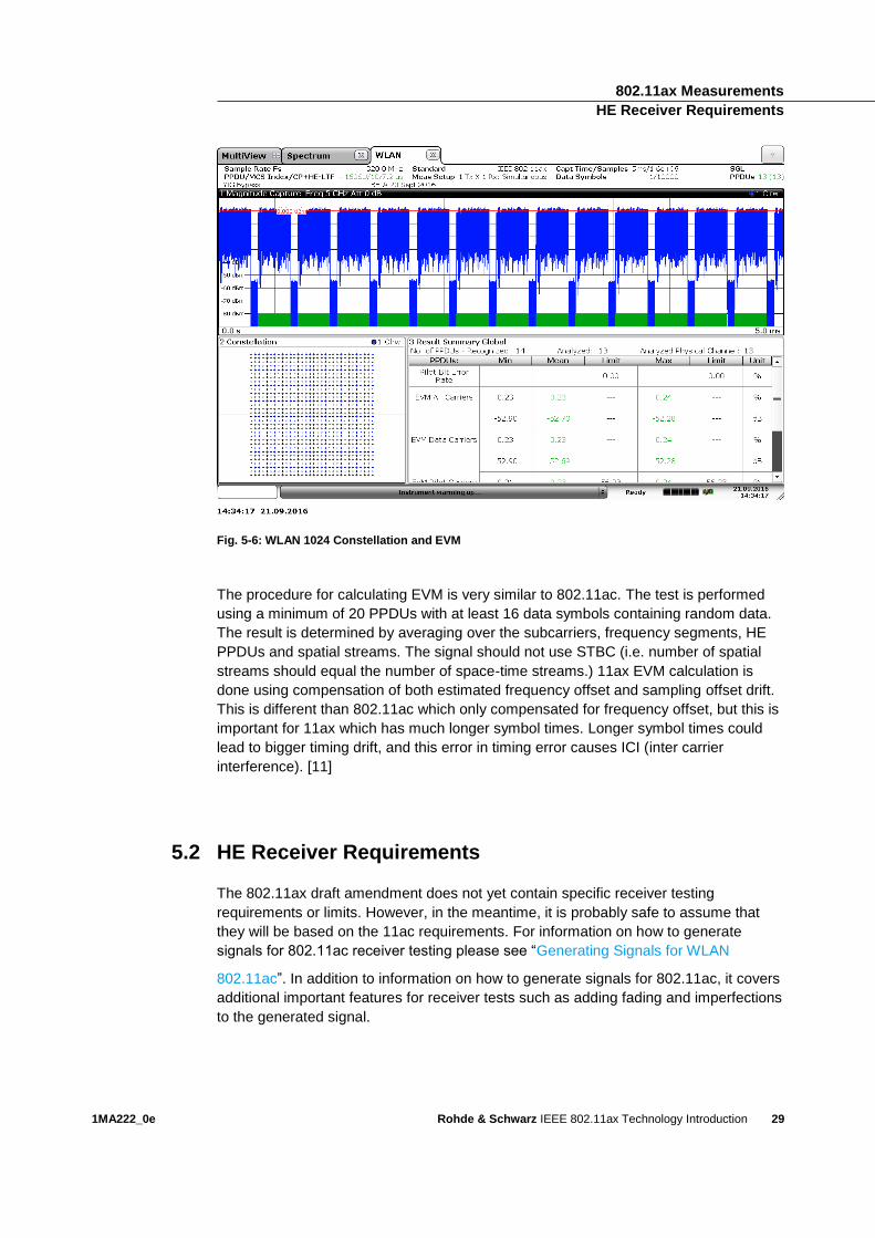
than -45 dB for the 1024 QAM case. Fig. 5-6 shows a screenshot from the R&S FSW
achieving -52 dB EVM for a 160 MHz 1024 QAM WLAN signal.
For OFDMA, the EVM will be computed per RU and the limit depends on the MCS. In
the downlink, the EVM requirements are given in Table 5-4. For uplink OFDMA, the
STA will transmit only one RU in the HE trigger based PPDU. Therefore, there are two
parts to the EVM test. The first is measuring the EVM of the transmitted RU and the
limit is based on the MCS although the exact values for those limits are not yet
determined. The second part is a measurement of the EVM of the unoccupied
subcarriers outside of the RU. This is basically a measure of how much power is being
transmitted in the unoccupied subcarriers since this unwanted power contributes to the
interference in the allocated RU. The unoccupied tone EVM will be averaged over 26
subcarriers (2 MHz) to avoid frequency selective variations. There will be one EVM
limit that is still to be determined for all the unused tones and will be independent of RU
size.
Table 5-4: EVM specification (for HE SU, Extended Range, and MU PPDU)
MCS Modulation Coding Rate EVM (dB)
0 BPSK 1/2 -5
1 QPSK 1/2 -10
2 QPSK 3/4 -13
3 16-QAM 1/2 -16
4 16-QAM 3/4 -19
5 64-QAM 2/3 -22
6 64-QAM 3/4 -25
7 64-QAM 5/6 -27
8 256-QAM 3/4 -30
9 256-QAM 5/6 -32
10 1024-QAM 3/4 -35
11 1024-QAM 5/6 -35
802.11ax Measurements HE Receiver Requirements
1MA222_0e Rohde & Schwarz IEEE 802.11ax Technology Introduction
29
Fig. 5-6: WLAN 1024 Constellation and EVM
The procedure for calculating EVM is very similar to 802.11ac. The test is performed
using a minimum of 20 PPDUs with at least 16 data symbols containing random data.
The result is determined by averaging over the subcarriers, frequency segments, HE
PPDUs and spatial streams. The signal should not use STBC (i.e. number of spatial
streams should equal the number of space-time streams.) 11ax EVM calculation is
done using compensation of both estimated frequency offset and sampling offset drift.
This is different than 802.11ac which only compensated for frequency offset, but this is
important for 11ax which has much longer symbol times. Longer symbol times could
lead to bigger timing drift, and this error in timing error causes ICI (inter carrier
interference). [11]
5.2 HE Receiver Requirements
The 802.11ax draft amendment does not yet contain specific receiver testing
requirements or limits. However, in the meantime, it is probably safe to assume that
they will be based on the 11ac requirements. For information on how to generate
signals for 802.11ac receiver testing please see “Generating Signals for WLAN
802.11ac”. In addition to information on how to generate signals for 802.11ac, it covers
additional important features for receiver tests such as adding fading and imperfections
to the generated signal.
802.11ax Measurements HE Trigger Based PPDU Specifications
1MA222_0e Rohde & Schwarz IEEE 802.11ax Technology Introduction
30
5.3 HE Trigger Based PPDU Specifications
802.11ax adds many new requirements for the HE Trigger based (HE_Trig) PPDU
case. These specifications are needed because UL OFDMA and UL MU-MIMO rely on
transmission accuracy and synchronization by user devices for effective operation.
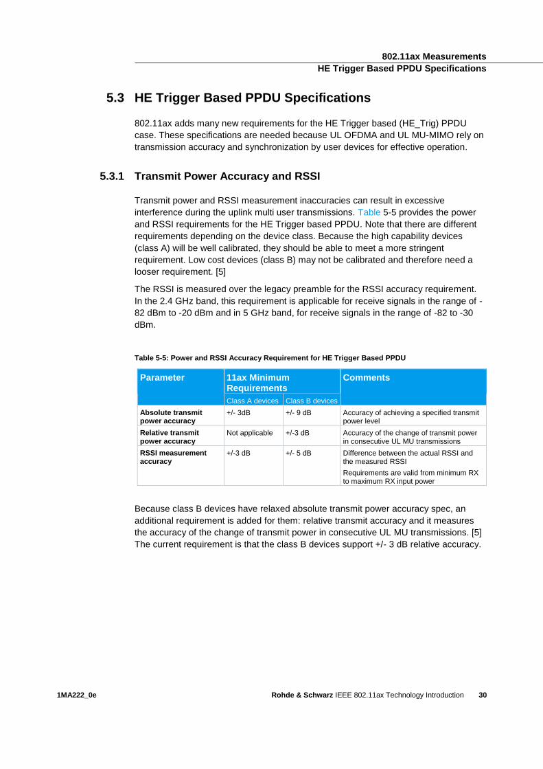
5.3.1 Transmit Power Accuracy and RSSI
Transmit power and RSSI measurement inaccuracies can result in excessive
interference during the uplink multi user transmissions. Table 5-5 provides the power
and RSSI requirements for the HE Trigger based PPDU. Note that there are different
requirements depending on the device class. Because the high capability devices
(class A) will be well calibrated, they should be able to meet a more stringent
requirement. Low cost devices (class B) may not be calibrated and therefore need a
looser requirement. [5]
The RSSI is measured over the legacy preamble for the RSSI accuracy requirement.
In the 2.4 GHz band, this requirement is applicable for receive signals in the range of -
82 dBm to -20 dBm and in 5 GHz band, for receive signals in the range of -82 to -30
dBm.
Table 5-5: Power and RSSI Accuracy Requirement for HE Trigger Based PPDU
Parameter 11ax Minimum Requirements
Comments
Class A devices Class B devices
Absolute transmit power accuracy
+/- 3dB +/- 9 dB Accuracy of achieving a specified transmit power level
Relative transmit power accuracy
Not applicable +/-3 dB Accuracy of the change of transmit power in consecutive UL MU transmissions
RSSI measurement accuracy
+/-3 dB +/- 5 dB Difference between the actual RSSI and the measured RSSI
Requirements are valid from minimum RX to maximum RX input power
Because class B devices have relaxed absolute transmit power accuracy spec, an
additional requirement is added for them: relative transmit accuracy and it measures
the accuracy of the change of transmit power in consecutive UL MU transmissions. [5]
The current requirement is that the class B devices support +/- 3 dB relative accuracy.
802.11ax Measurements HE Trigger Based PPDU Specifications
1MA222_0e Rohde & Schwarz IEEE 802.11ax Technology Introduction
31
5.3.2 Carrier Frequency Offset (CFO) error and timing drift
Carrier Frequency offset error contributes to interference between users. 802.11ax,
therefore, requires user devices to perform CFO correction relative to the Trigger frame
frequency to reduce the amount of the residual CFO at the AP during the UL MU
transmission. For the CFO requirement, the CFO error statistics are measured and at
the 10% point of the CCDF curve, the CFO error must be less than 350 Hz. The
measurement is made in the primary 20 MHz channel at a received power of -60 dBm.
The CFO is measured after the HE-SIG-A field in the HE_Trig PPDU.
In order for the AP to decode packets from multiple users, the UL OFDMA and MU-
MIMO transmissions need to be synchronized when the AP receives them. After the
users receive information from the AP to trigger the uplink transmissions, they transmit
the HE_Trig PPDU at a specified time. The accuracy of this time is required to be +/-
0.4 µs relative to the frame sent by the AP to trigger the UL transmissions.
Literature References
1MA222_0e Rohde & Schwarz IEEE 802.11ax Technology Introduction
32
6 Literature
6.1 References
[1] IEEE 802, IEEE P802.11ax/D0.4, 2016.
[2] IEEE 802, "802.11 PROJECT AUTHORIZATIONS (PARs)," 1 April
2014. [Online]. Available:
http://www.ieee802.org/11/PARs/P802.11ax.pdf. [Accessed 26 June
2016].
[3] IEEE 802, "IEEE 802.11 Documents," 11 November 2013. [Online].
Available: https://mentor.ieee.org/802.11/dcn/13/11-13-1443-00-0hew-
liaison-from-wi-fi-alliance-on-hew-use-cases.ppt. [Accessed 26 June
2016].
[4] R. Porat and et al, "IEEE 802.11 Documents," 12 January 2015.
[Online]. Available: https://mentor.ieee.org/802.11/dcn/15/11-15-0099-
04-00ax-payload-symbol-size-for-11ax.pptx.
[5] A. Bharadwaj, "IEEE 802.11 Documents," 18 January 2016. [Online].
Available: https://mentor.ieee.org/802.11/dcn/16/11-16-0053-00-00ax-
requirements-for-ul-mu-transmissions.pptx.
[6] H. Zhang, "IEEE 802.11 Documents," 12 September 2015. [Online].
Available: https://mentor.ieee.org/802.11/dcn/15/11-15-0810-01-00ax-
he-phy-padding-and-packet-extension.pptx.
[7] L. Yang and et. al., "IEEE802.11 Documents," July 13 2015. [Online].
Available: https://mentor.ieee.org/802.11/documents?is_dcn=819.
[8] S. Azizi, J. Choi and et.al., "IEEE 802.11 Documents," 13 May 2015.
[Online]. Available: https://mentor.ieee.org/802.11/dcn/15/11-15-0330-
05-00ax-ofdma-numerology-and-structure.pptx.
[9] R. Porat and et al, "IEEE802.11 Documents," 13 July 2015. [Online].
Available: https://mentor.ieee.org/802.11/dcn/15/11-15-0873-00-00ax-
sig-b-encoding-structure.pptx.
[10] K. Josiam, "IEEE 802.11 Documents," May 2016. [Online]. Available:
https://mentor.ieee.org/802.11/dcn/16/11-16-0928-02-00ax-cr-on-
section-26-3-9-8-he-sig-b.docx.
[11] D. Lee, "IEEE802.11 Documents," 12 September 2016. [Online].
Available: https://mentor.ieee.org/802.11/dcn/16/11-16-1190-01-00ax-
tx-quality-requirements.pptx.
Abbreviations/Acronyms/Initialisms References
1MA222_0e Rohde & Schwarz IEEE 802.11ax Technology Introduction
33
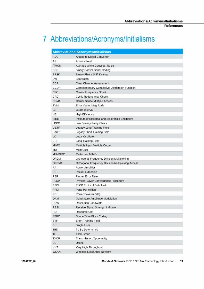
7 Abbreviations/Acronyms/Initialisms
Abbreviations/Acronyms/Initialisms
ADC Analog to Digital Converter
AP Access Point
AWGN Average White Gaussian Noise
BCC Binary Convolutional Coding
BPSK Binary Phase Shift Keying
BW Bandwidth
CCA Clear Channel Assessment
CCDF Complementary Cumulative Distribution Function
CFO Carrier Frequency Offset
CRC Cyclic Redundancy Check
CSMA Carrier Sense Multiple Access
EVM Error Vector Magnitude
GI Guard Interval
HE High Efficiency
IEEE Institute of Electrical and Electronics Engineers
LDPC Low Density Parity Check
L-LTF Legacy Long Training Field
L-STF Legacy Short Training Field
LO Local Oscillator
LTF Long Training Field
MIMO Multiple Input Multiple Output
MU Multi User
MU-MIMO Multi-User MIMO
OFDM Orthogonal Frequency Division Multiplexing
OFDMA Orthogonal Frequency Division Multiplexing Access
PA Power Amplifier
PE Packet Extension
PER Packet Error Rate
PLCP Physical Layer Convergence Procedure
PPDU PLCP Protocol Data Unit
PPM Parts Per Million
PS Power Save (mode)
QAM Quadrature Amplitude Modulation
RBW Resolution Bandwidth
RSSI Receive Signal Strength Indicator
RU Resource Unit
STBC Space Time Block Coding
STF Short Training Field
SU Single User
TBD To Be Determined
TG Task Group
TXOP Transmission Opportunity
UL Uplink
VHT Very High Throughput
WLAN Wireless Local Area Network
IEEE 802.11ax Technology Introduction
34
Rohde & Schwarz
The Rohde & Schwarz electronics group offers
innovative solutions in the following business fields:
test and measurement, broadcast and media, secure
communications, cybersecurity, radiomonitoring and
radiolocation. Founded more than 80 years ago, this
independent company has an extensive sales and
service network and is present in more than 70
countries.
The electronics group is among the world market
leaders in its established business fields. The
company is headquartered in Munich, Germany. It
also has regional headquarters in Singapore and
Columbia, Maryland, USA, to manage its operations
in these regions.
Regional contact
Europe, Africa, Middle East +49 89 4129 12345 [email protected] North America 1 888 TEST RSA (1 888 837 87 72) [email protected] Latin America +1 410 910 79 88 [email protected] Asia Pacific +65 65 13 04 88 [email protected]
China +86 800 810 82 28 |+86 400 650 58 96 [email protected]
Sustainable product design
ı Environmental compatibility and eco-
footprint
ı Energy efficiency and low emissions
ı Longevity and optimized total cost of
ownership
This white paper and the supplied programs may
only be used subject to the conditions of use set
forth in the download area of the Rohde & Schwarz
website.
R&S® is a registered trademark of Rohde & Schwarz GmbH & Co.
KG; Trade names are trademarks of the owners.
Rohde & Schwarz GmbH & Co. KG
Mühldorfstraße 15 | 81671 Munich, Germany
Phone + 49 89 4129 - 0 | Fax + 49 89 4129 – 13777
www.rohde-schwarz.com
PA
D-T
-M: 3573.7
380.0
2/0
2.0
5/E
N/


![Single User MAC Level Throughput Comparision: IEEE … · O. Sharon, Y. Alpert. 802.11ac [3] [4]. IEEE 802.11ax is predicted to have maximum capacity of around 9.5 Gbps in 2.4 and/or](https://img.pdfslide.us/doc/110x75/5bab70e709d3f27d588c1424/single-user-mac-level-throughput-comparision-ieee-o-sharon-y-alpert-80211ac.jpg)

![VRIF Guidelines 2 · 2020. 6. 4. · Amendment Enhancements for High Efficiency WLAN (IEEE 802.11ax) [ACN] Ambisonic data exchange formats – Ambisonic Channel Number (Wikipedia)](https://img.pdfslide.us/doc/110x75/5fc06d1b5a042e3fdb268930/vrif-guidelines-2-2020-6-4-amendment-enhancements-for-high-efficiency-wlan.jpg)