Embed Size (px)
Citation preview

Design Criteria
Reference Standards
ANALYSIS OF GLASS
RAIL BASE MOLDING
ATTACHMENT
WJE Wiss, Janny, Elstner Associates, Inc.
Morse Industries
Glass Rail Base Molding Attachment Analysis
NSA
MJS
1/21
97079807/22/97
Kent, Washington
330 Pfingsten Rd., Northbrook Illinois 60062
Made by: Sheet #
Project #
Checked by:
Date:
The purpose of these calculations is to check the adequacy of the connection of the Morse Industries glass hand railing
base shoe molding (two types - see fig. 1) to either a concrete or steel substrate. The analysis considers the adequacy of
the connection when when the standard height railing (42 in.) is subjected to live loads required by model building codes.
The analysis is limited to the base shoe to substrate connection. Analysis of stresses in the glass, top rail, and base shoe
molding are beyond the scope of these calculations.
Analysis of glass railing base shoe connections (4 types considered)
Model Code regulations require a uniform loading of 50 lbs per lineal foot (plf) or a 200-lb concentrated load to be resisted
at the top rail, whichever creates the most severe stresses.
For the base shoe connection, the 200-lb load applied in a horizontal direction at the top handrail causes the maximum
stresses in the connections.
The analysis considered shear and moment due to the 200 lb load being resisted by 3 - SAE Grade 5, 1/2" diameter cap
screws (F =120,000 psi and F = 92,000 psi) and 2 - ASTM A307, 3/8" diameter T-bolts (F = 60,000 psi)
- The Aluminum Associations (AA), , Specifications & Guidelines for Aluminum Structures, October,
1994.
- American Architectural Manufacturers Association AAMA), (AAMA TIR-A9-1991), 1991
- American Concrete Institute (ACI), (ACI 318-95), 1995.
- American Institute of Steel Construction (AISC), ( Allowable Stress Design), 9th Edition, 1989.
- Industrial Fasteners Institute (IFI), , 6th Edition, 1988
- International Conference of Building Officials (ICBO), (UBC), Structural Engineering Design Provisions,
Volume 2, 1997.
- Precast/Prestressed Concrete Institute (PCI), , MNL 120, 4th Edition, 1992.
Aluminum Design Manual
Metal Curtain Wall Fasteners
Building Code Requirements for Structural Concrete
Manual of Steel Construction
Fastener Standards
Uniform Building Code
PSI Design Handbook
Case 1: Concrete surface mounted (see fig. 2)
Case 2: Concrete flush mounted (see fig. 3)
Case 3: Steel fascia mounted (see fig. 4)
Case 4: Steel fascia mounted (see fig. 5)
Note: Relevant reference to these documents in the calculations is made with [ ] (square brackets).
u uy

Figure 1 - 6063-T6 Aluminum Base Shoe Moldings
Figure 2 - Surface Mounted Base Shoe Molding
ANALYSIS OF GLASS
RAIL BASE MOLDING
ATTACHMENT
WJE Wiss, Janny, Elstner Associates, Inc.
Morse Industries
Glass Rail Base Molding Attachment Analysis
NSA
MJS
2/21
97079807/22/97
Kent, Washington
330 Pfingsten Rd., Northbrook Illinois 60062
Made by: Sheet #
Project #
Checked by:
Date:
1"
3/4" 3/4"
2 1/2"2 1/2"
4 1/8" 4 1/8"
1"
Glass
Aluminum Base Assembly
Centered on Steel Plate
1/2" Cap Screws 12" O.C. tapped
into Steel Plate1/4" Mimimum
3 1/4"5" (Minimum Slab Thickness)
1/2" continuous Steel Plate
Anchors 3/8" x 3" ASTM A307 T-Bolts
NOTE: Plate anchorage alterate:
3/8" x 4 1/8" Headed Concrete
Studs at 1' - 6" O.C. in a
5 1/2" minimum slab thickness
4000 PSI Normal Weight Concrete (Min.)
Minimum Edge Distance
5 1/2"

Figure 3 - Flush Mounted Base Shoe Molding (recessed in concrete)
Figure 4 - Fascia Mounted Base Shoe Molding
ANALYSIS OF GLASS
RAIL BASE MOLDING
ATTACHMENT
WJE Wiss, Janny, Elstner Associates, Inc.
Morse Industries
Glass Rail Base Molding Attachment Analysis
NSA
MJS
3/21
97079807/22/97
Kent, Washington
330 Pfingsten Rd., Northbrook Illinois 60062
Made by: Sheet #
Project #
Checked by:
Date:
Glass
Glass
Aluminum Base Assembly
Centered on Steel Plate
Aluminum Base Assembly
1/2" Cap Screws 12" O.C. tapped
into Steel Plate
1/2" Cap Screws 12" O.C. tapped
into Steel Plate
1/4" Mimimum
Min. 3 1/2" Concrete under Plate
Min. Concrete Slab thickness 8"
1/2" continuous Steel Plate
Minimum Steel Thickness = 3/8"
1/4" minimum
NOTE: Design of Steel
Side Plate by others using
code Handrail Loading(s)
4000 PSI Normal Weight Concrete (Min.)
Minimum Edge Distance
5 1/2"

Figure 5 - Fascia Mounted Base Shoe Molding
ANALYSIS OF GLASS
RAIL BASE MOLDING
ATTACHMENT
WJE Wiss, Janny, Elstner Associates, Inc.
Morse Industries
Glass Rail Base Molding Attachment Analysis
NSA
MJS
4/21
97079807/22/97
Kent, Washington
330 Pfingsten Rd., Northbrook Illinois 60062
Made by: Sheet #
Project #
Checked by:
Date:
Glass
Aluminum Base Assembly
1/2" Cap Screws 12" O.C. tapped
into Steel Plate
Minimum Steel thickness = 3/8"
1/4" minimum
NOTE: Design of Steel
Angle connection by others
using code Handrail loading(s)

Glass Rail Base Molding Attachment Analysis
Analysis of Glass Railing Base Shoe Connections
Railing LoadApplication
200 lbs at end of railing(into page - see above)
45 degree Distribution fan
Cap Screw Spacing12" 12" 12" 12" 12" 6"
6"1'-6"1'-6"1'-6"1'-6"T-Bolt Spacing (Case I)
Maximum end distance assumed
(Ref: 1997 UBC)
Lateral Load
per Table 16-B:
Concentrated Load 200 lbs.(not acting cumulatively with the above load)
50 lbs/ft
ANALYSIS OF GLASS
RAIL BASE MOLDING
ATTACHMENT
WJE Wiss, Janny, Elstner Associates, Inc.
Morse Industries
NSA
MJS
5/21
97079807/22/97
Kent, Washington
330 Pfingsten Rd., Northbrook Illinois 60062
Made by: Sheet #
Project #
Checked by:
Date:
3'-6"
3'-6" Railing ht.
45 degree
Substrate
200 lbs
3'-6"
Glass Rail Base Molding Attachment Analysis
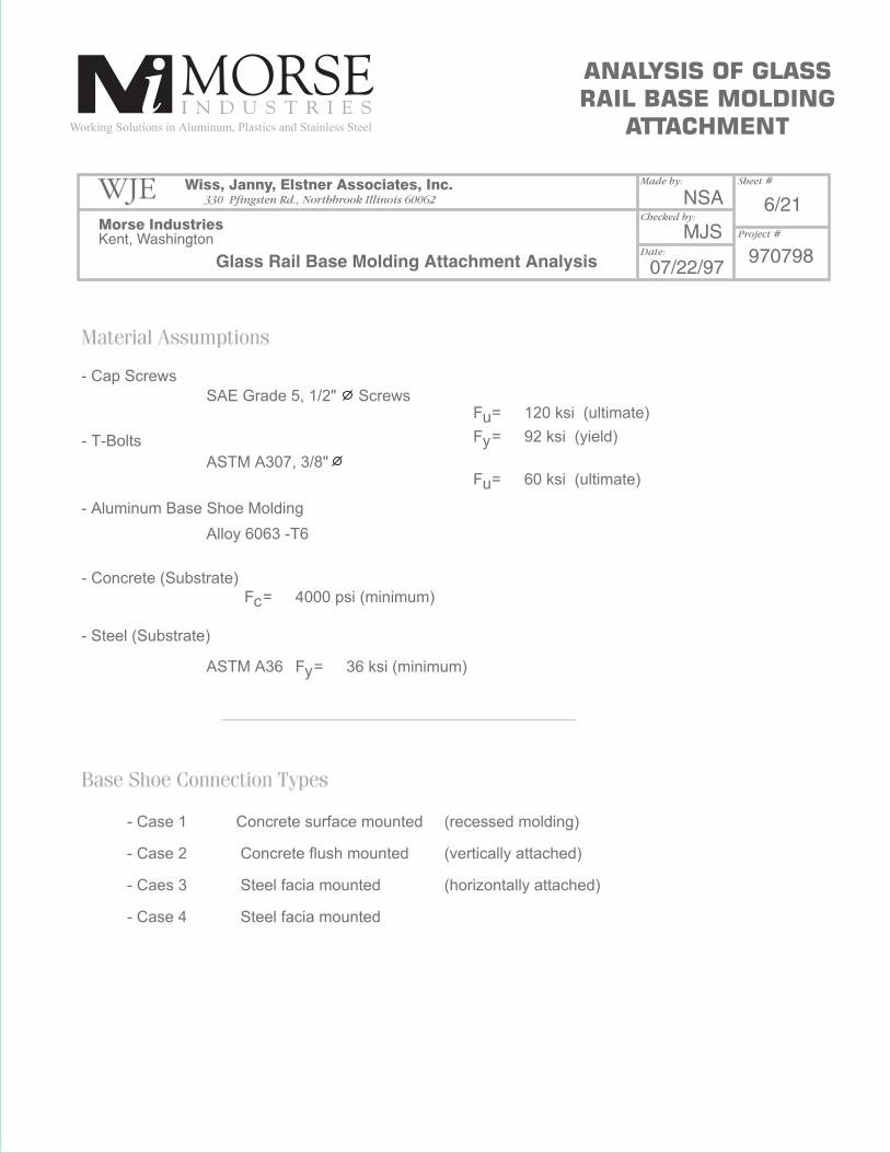
Material Assumptions
Base Shoe Connection Types
- Cap Screws
SAE Grade 5, 1/2" ScrewsF =
F =
F =
F =
F =
120 ksi (ultimate)
60 ksi (ultimate)
4000 psi (minimum)
36 ksi (minimum)
92 ksi (yield)
u
u
c
y
y
ASTM A307, 3/8"
ASTM A36
Alloy 6063 -T6
- T-Bolts
- Aluminum Base Shoe Molding
- Concrete (Substrate)
- Steel (Substrate)
- Case 1
- Case 2
- Caes 3
- Case 4
Concrete surface mounted
Concrete flush mounted
Steel facia mounted
Steel facia mounted
(recessed molding)
(vertically attached)
(horizontally attached)
ANALYSIS OF GLASS
RAIL BASE MOLDING
ATTACHMENT
WJE Wiss, Janny, Elstner Associates, Inc.
Morse Industries
NSA
MJS
6/21
97079807/22/97
Kent, Washington
330 Pfingsten Rd., Northbrook Illinois 60062
Made by: Sheet #
Project #
Checked by:
Date:
Glass Rail Base Molding Attachment Analysis
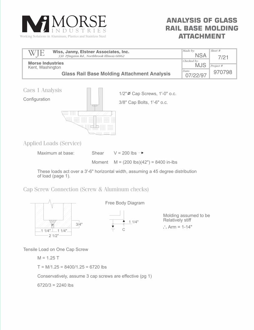
Caes 1 Analysis
Applied Loads (Service)
Cap Screw Connection (Screw & Aluminum checks)
Configuration
Tensile Load on One Cap Screw
Maximum at base:
M = 1.25 T
T = M/1.25 = 8400/1.25 = 6720 lbs
Conservatively, assume 3 cap screws are effective (pg 1)
6720/3 = 2240 lbs
Free Body Diagram
1 1/4" 1 1/4"
2 1/2"
1 1/4"
C
3/4"
Molding assumed to beRelatively stiff
Arm = 1-14"
Shear
Moment
V = 200 lbs
M = (200 lbs)(42") = 8400 in-lbs
These loads act over a 3'-6" horizontal width, assuming a 45 degree distributionof load (page 1).
3/8" Cap Bolts, 1'-6" o.c.
ANALYSIS OF GLASS
RAIL BASE MOLDING
ATTACHMENT
WJE Wiss, Janny, Elstner Associates, Inc.
Morse Industries
NSA
MJS
7/21
97079807/22/97
Kent, Washington
330 Pfingsten Rd., Northbrook Illinois 60062
Made by: Sheet #
Project #
Checked by:
Date:
1/2" Cap Screws, 1'-0" o.c.
Glass Rail Base Molding Attachment Analysis
2 2
2
2
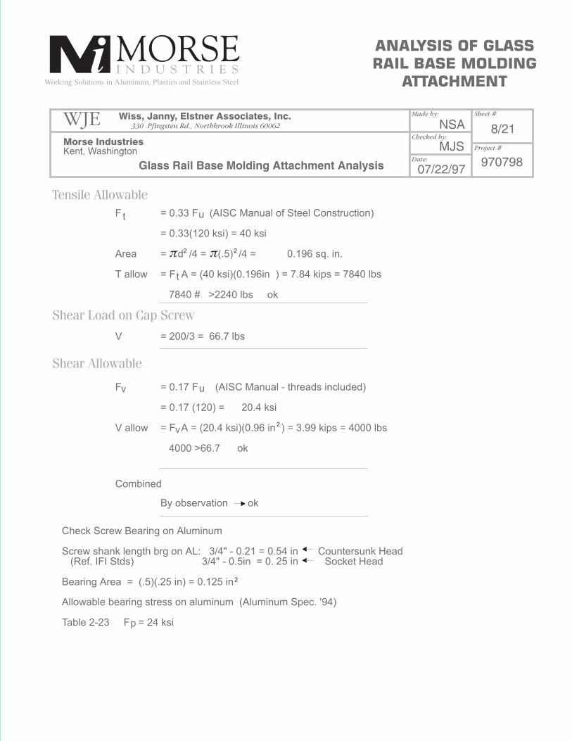
Tensile Allowable
Shear Load on Cap Screw
Shear Allowable
F
Area
T allow
t
v
25 in
u
u
p
v
t
V
F
V allow
Combined
Check Screw Bearing on Aluminum
Screw shank length brg on AL: 3/4" - 0.21 = 0.54 in Countersunk Head(Ref. IFI Stds) 3/4" - 0.5in = 0. Socket Head
Bearing Area = (.5)(.25 in) = 0.125 in
Allowable bearing stress on aluminum (Aluminum Spec. '94)
Table 2-23 F = 24 ksi
= 0.33 F (AISC Manual of Steel Construction)
= 0.33(120 ksi) = 40 ksi
= d /4 = (.5) /4 = 0.196 sq. in.
= F A = (40 ksi)(0.196in ) = 7.84 kips = 7840 lbs
7840 # >2240 lbs ok
= 200/3 = 66.7 lbs
= 0.17 F (AISC Manual - threads included)
= 0.17 (120) = 20.4 ksi
= F A = (20.4 ksi)(0.96 in ) = 3.99 kips = 4000 lbs
4000 >66.7 ok
By observation ok
ANALYSIS OF GLASS
RAIL BASE MOLDING
ATTACHMENT
WJE Wiss, Janny, Elstner Associates, Inc.
Morse Industries
NSA
MJS
8/21
97079807/22/97
Kent, Washington
330 Pfingsten Rd., Northbrook Illinois 60062
Made by: Sheet #
Project #
Checked by:
Date:
Glass Rail Base Molding Attachment Analysis
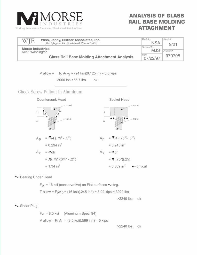
Check Screw Pullout in Aluminum
Bearing Under Head
Shear Plug
V allow = F A = (24 ksi)(0.125 in) = 3.0 kips
F = 16 ksi (conservative) on Flat surfaces brg.
T allow = F A = (16 ksi)(.245 in ) = 3.92 kips = 3920 lbs
F = 8.5 ksi (Aluminum Spec '94)
V allow = F A = (8.5 ksi)(.589 in ) = 5 kips
>2240 lbs ok
>2240 lbs ok
Countersunk Head
.21 .5
H H1/2" 1/2"
.079 3/4"
Socket Head
3000 lbs >66.7 lbs ok
A = /4 (.79 - .5 )
= 0.294 in
= dh
= (.79")(3/4" - .21)
= 1.34 in
= /4 (.75 - .5 )
= 0.245 in
= dh
= (.75")(.25)
= 0.589 in critical
A
A A
p
p brg
p
v
u u2
2
2
2
22
2
2
22
p p
p
v v
ANALYSIS OF GLASS
RAIL BASE MOLDING
ATTACHMENT
WJE Wiss, Janny, Elstner Associates, Inc.
Morse Industries
NSA
MJS
9/21
97079807/22/97
Kent, Washington
330 Pfingsten Rd., Northbrook Illinois 60062
Made by: Sheet #
Project #
Checked by:
Date:

Glass Rail Base Molding Attachment Analysis
Cap Screw into Steel Plate
Anchor in Concrete (Steel check)
1/2" thick Steel Plate
(Ref: "Metal Curtain Wall Fasteners", from AAMA)
Table 4 Thread Stripping Area - Internal (sq. in. / thread)
1/2" TSA(I) = 0.036
Number of Threads / Inch N = 13 (UNC)
Min. PL - Thickness to achieve Tension Force = Allow. Shear Stress TSA(I) (N) + N
MT = (.4)(36,000)(0.86)(13) + 13
16099 + 13 = 0.56 in 1/2" PL provided
Reduction Factor = .5/.56 = 0.88
Tallow = (7840 lbs)(.88) = 6900 lbs
3/8" A307 bolts assumed to act as studs.
Bolt Tension
4 in wide plate assume Arm = 4/2 = 2 in
On page 1, 2 stud bolts assumed effective
>2240 lbs ok
T = Arm = (2 in)(2 bolts)= 2100 lbs/bolt
M 8400 in lbs
F = .4F
7840 lbs
Allowable Tension 1
7840
1
1
v y
ANALYSIS OF GLASS
RAIL BASE MOLDING
ATTACHMENT
WJE Wiss, Janny, Elstner Associates, Inc.
Morse Industries
NSA
MJS
10/21
97079807/22/97
Kent, Washington
330 Pfingsten Rd., Northbrook Illinois 60062
Made by: Sheet #
Project #
Checked by:
Date:

2 2
2
Allowable Tension
Shear in Bolt
Allowable Shear
Check Interaction
Area
T allow
F
V allow
F
F
Allowable
v
v
actu
al
t
t
t t
t
v
200 lbs / 2 bolts = 100 lbs
>2100 lbs ok
>100 lbs ok
= (3/8") /4 = 0.11 in
= (20 ksi)(.11 in ) = 2.2 kips = 2200 lbs
= 10 ksi (Ref. AISC MAnual)
= (10 ksi)(.11) = 1100 lbs
= 100/.11 = 909 psi
= 2100/.11 = 19,090 psi = 19.1 ksi
F = 26-1.8(0.91 ksi) = 24.36 ksi use 20 ksi as default
F > f ok
(Ref: AISC Manual) F = 20 ksi
(AISC Table J3.3) F = 26 -1.8 F <20
t
ANALYSIS OF GLASS
RAIL BASE MOLDING
ATTACHMENT
WJE Wiss, Janny, Elstner Associates, Inc.
Morse Industries
Glass Rail Base Molding Attachment Analysis
NSA
MJS
11/21
97079807/22/97
Kent, Washington
330 Pfingsten Rd., Northbrook Illinois 60062
Made by: Sheet #
Project #
Checked by:
Date:
2
22 3
3
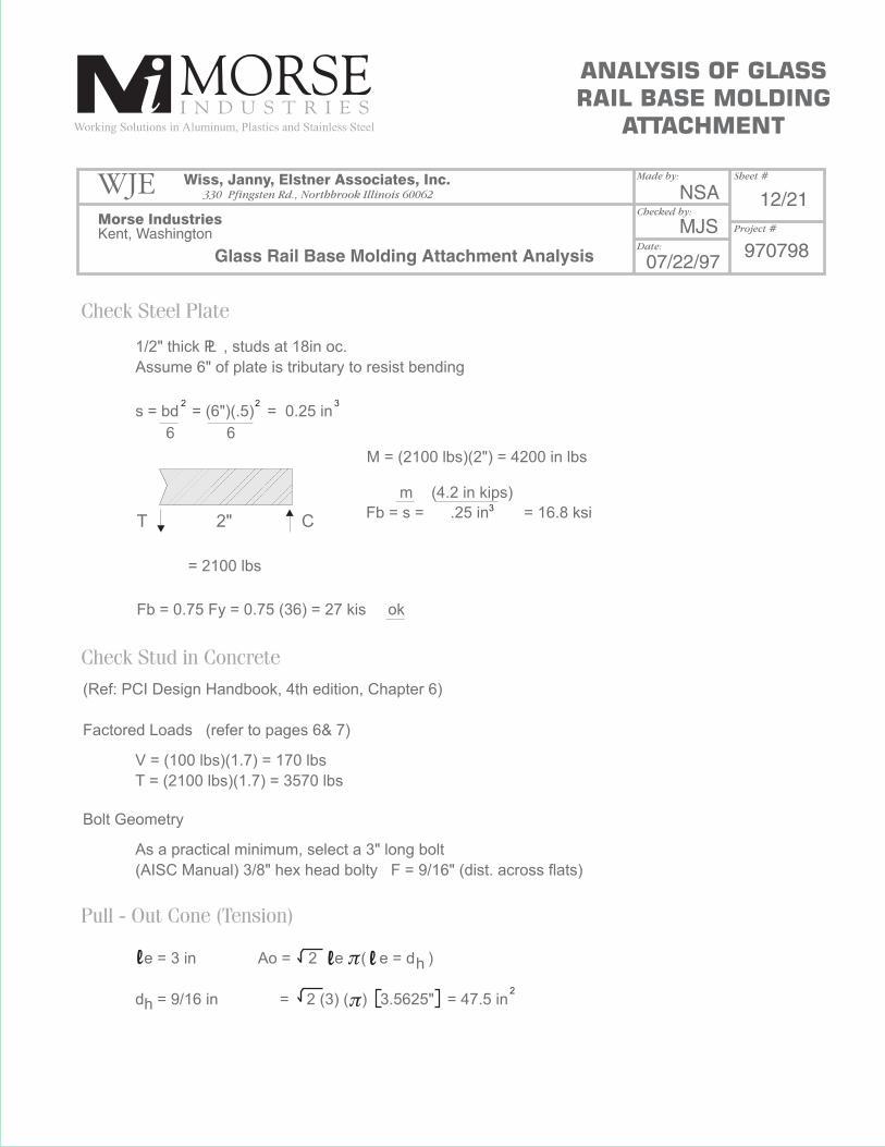
Check Steel Plate
Check Stud in Concrete
Pull - Out Cone (Tension)
1/2" thick P , studs at 18in oc.
Assume 6" of plate is tributary to resist bending
L
s = bd = (6")(.5) = 0.25 in
M = (2100 lbs)(2") = 4200 in lbs
Fb = s = .25 in = 16.8 ksi
Fb = 0.75 Fy = 0.75 (36) = 27 kis ok
m (4.2 in kips)
= 2100 lbs
T 2" C
6 6
(Ref: PCI Design Handbook, 4th edition, Chapter 6)
Factored Loads (refer to pages 6& 7)
Bolt Geometry
V = (100 lbs)(1.7) = 170 lbs
T = (2100 lbs)(1.7) = 3570 lbs
As a practical minimum, select a 3" long bolt
(AISC Manual) 3/8" hex head bolty F = 9/16" (dist. across flats)
e = 3 in
d = 9/16 in
Ao = 2 e ( e = d )
= 2 (3) ( ) 3.5625" = 47.5 in
h
h
ANALYSIS OF GLASS
RAIL BASE MOLDING
ATTACHMENT
WJE Wiss, Janny, Elstner Associates, Inc.
Morse Industries
Glass Rail Base Molding Attachment Analysis
NSA
MJS
12/21
97079807/22/97
Kent, Washington
330 Pfingsten Rd., Northbrook Illinois 60062
Made by: Sheet #
Project #
Checked by:
Date:
l l l

1.5
1.5
2
2
Shear
Examine Shear Parameters
F'c = 4000 psi (mimimum)
pc = Ao (2.8 x F'c)
= (0.85) (47.5) (2.8) 4000
= 7150 lbs >3570 obs ok
Min. edge distance = 15Db = 15 (3/8") = 5.625 in
Vc = 628db f'c where = number of studs
= (.85) (628) (.375) (1.0) 4000 (1.0)
= 4750 lbs > 170 lbs ok
Bolt length + P Thickness = 3" + 1/2" = 3 1/2"
Say practical min. edge dist. = 1.5 (3.5) = 5 1/4" = de
* Width Effect Cw = 1.0 (only one stud in group)
* Thickness Effect = h <1.0
* Corner Effect Cc = 1.0
Keep edge distance >5 1/4" in both directions.
Only becomes a factor when h<1.3(5 1/4) = 6 7/8"
Select h = 5 in Ct = 5 = 0.73
6.875
Ct = 1.3de
L
= 12.5 de fc
= (.85)(12.5)(5.25) (1.0) 4000 = 8085 lbs
Vc
ANALYSIS OF GLASS
RAIL BASE MOLDING
ATTACHMENT
WJE Wiss, Janny, Elstner Associates, Inc.
Morse Industries
Glass Rail Base Molding Attachment Analysis
NSA
MJS
13/21
97079807/22/97
Kent, Washington
330 Pfingsten Rd., Northbrook Illinois 60062
Made by: Sheet #
Project #
Checked by:
Date:
l l
l l
ll

2
2 2
2
Check Combined
Weld bolt to plate
V = V' C C C
= (8085 lbs.) (1.0) (0.73) (1.0)
= 5092 lbs
c c ctw
Pc = 7150/ .85 = 8412 lbs
Vc = 4750/ .85 = 5588 lbs
3/8" 0 Length = 2 = (3/8") ( ) = 1.178
T = 2100 lbs 2.1 kips
V = 100 lbs = 0.1 kips
E70 electodes Fv = (.3) (70 ksi) = 21 ksi
3/16" weld Rw (3/16") (.707) (21 ksi) (1.178")
v
No need to check interaction as tension dominates
= 3.3 kips ok
1 Pu Vu
3750 + 170
8412 5588 < 1.0
1
.85
1
.85 .18 + .001 < 1.0
0.2 < 1.0 ok
Pc + Vc < 1.0
(Note: A 5" min. slab thickness is a practical minimum for this P & bolt combination)L
Other egn still governs
ANALYSIS OF GLASS
RAIL BASE MOLDING
ATTACHMENT
WJE Wiss, Janny, Elstner Associates, Inc.
Morse Industries
Glass Rail Base Molding Attachment Analysis
NSA
MJS
14/21
97079807/22/97
Kent, Washington
330 Pfingsten Rd., Northbrook Illinois 60062
Made by: Sheet #
Project #
Checked by:
Date:
l
l l
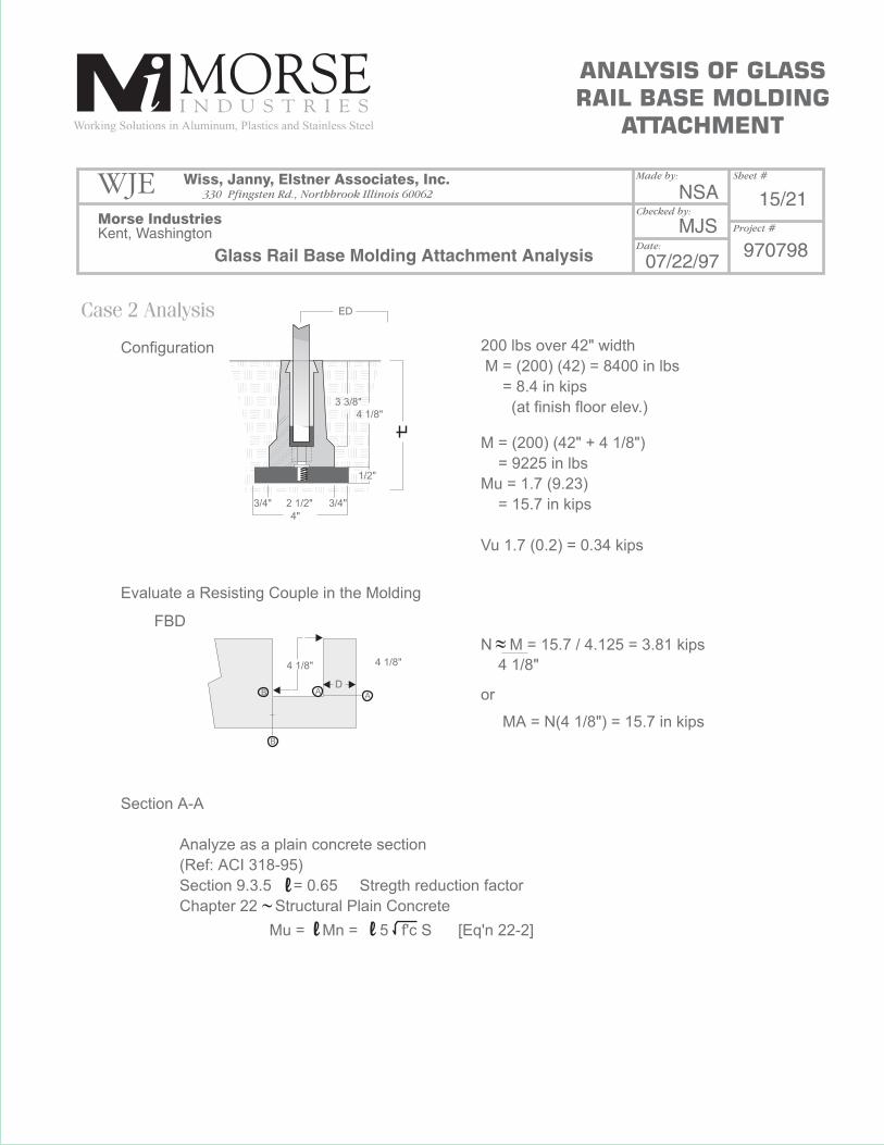
Case 2 Analysis
Configuration
Evaluate a Resisting Couple in the Molding
Section A-A
Analyze as a plain concrete section
(Ref: ACI 318-95)
Section 9.3.5 = 0.65 Stregth reduction factor
Chapter 22 Structural Plain Concrete
Mu = Mn = 5 f'c S [Eq'n 22-2]
FBD
200 lbs over 42" width
M = (200) (42) = 8400 in lbs
= 8.4 in kips
(at finish floor elev.)
N M = 15.7 / 4.125 = 3.81 kips
MA = N(4 1/8") = 15.7 in kips
4 1/8"
M = (200) (42" + 4 1/8")
= 9225 in lbs
Mu = 1.7 (9.23)
= 15.7 in kips
Vu 1.7 (0.2) = 0.34 kips
or
ED
ANALYSIS OF GLASS
RAIL BASE MOLDING
ATTACHMENT
WJE Wiss, Janny, Elstner Associates, Inc.
Morse Industries
Glass Rail Base Molding Attachment Analysis
NSA
MJS
15/21
97079807/22/97
Kent, Washington
330 Pfingsten Rd., Northbrook Illinois 60062
Made by: Sheet #
Project #
Checked by:
Date:
l
l l
3 3/8"
4 1/8"
4 1/8"4 1/8"
1/2"
3/4" 2 1/2"
4"
3/4"
DA
A
B
B
2
2 23
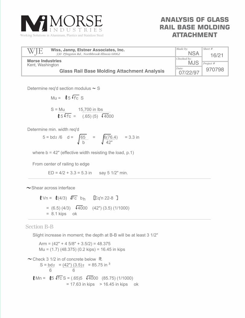
Determine req'd section modulus S
Determine min. width req'd
Shear across interface
Slight increase in moment; the depth at B-B will be at least 3 1/2"
Check 3 1/2 in of concrete below
S = bd = (42") (3.5) = 85.75 in
6 6
Arm = (42" + 4 5/8" + 3.5/2) = 48.375
Mu = (1.7) (48.375) (0.2 kips) = 16.45 in kips
Mn = 5 f'c S = (.65)5 4000 (85.75) (1/1000)
= 17.63 in kips > 16.45 in kips ok
b 42"
5 = bd /6 d = 65 = 6(76.4) = 3.3 in
Vn = (4/3) Fc b Eq'n 22-8h
= (6.5) (4/3) 4000 (42") (3.5) (1/1000)
= 8.1 kips ok
where b = 42" (effective width resisting the load, p.1)
From center of railing to edge
ED = 4/2 + 3.3 = 5.3 in say 5 1/2" min.
Mu = 5 f'c S
S = Mu 15,700 in lbs
5 f'c = (.65) (5) 4000
ANALYSIS OF GLASS
RAIL BASE MOLDING
ATTACHMENT
WJE Wiss, Janny, Elstner Associates, Inc.
Morse Industries
Glass Rail Base Molding Attachment Analysis
NSA
MJS
16/21
97079807/22/97
Kent, Washington
330 Pfingsten Rd., Northbrook Illinois 60062
Made by: Sheet #
Project #
Checked by:
Date:
Section B-B
l
l
l l
ll
PL
2
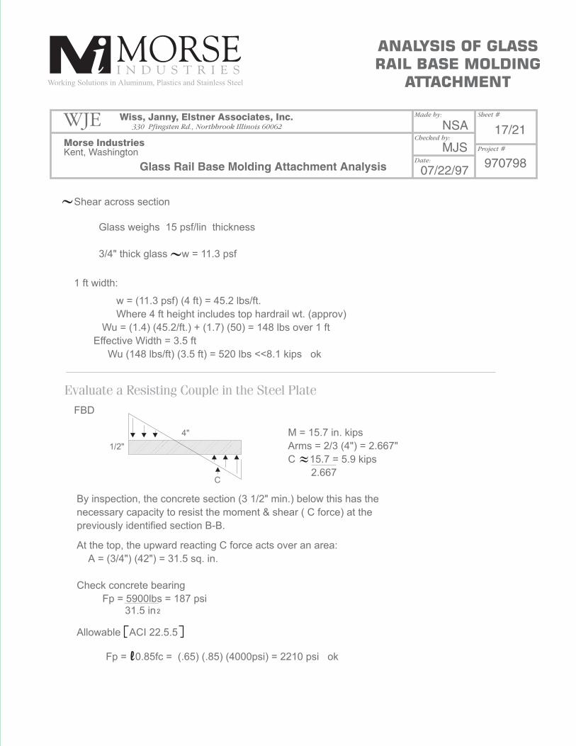
Shear across section
FBD
4"
1/2"
C
Evaluate a Resisting Couple in the Steel Plate
1 ft width:
By inspection, the concrete section (3 1/2" min.) below this has the
necessary capacity to resist the moment & shear ( C force) at the
previously identified section B-B.
At the top, the upward reacting C force acts over an area:
A = (3/4") (42") = 31.5 sq. in.
Check concrete bearing
Fp = 5900lbs = 187 psi
Allowable ACI 22.5.5
Fp = 0.85fc = (.65) (.85) (4000psi) = 2210 psi ok
31.5 in
M = 15.7 in. kips
Arms = 2/3 (4") = 2.667"
C 15.7 = 5.9 kips
2.667
Glass weighs 15 psf/lin thickness
3/4" thick glass w = 11.3 psf
w = (11.3 psf) (4 ft) = 45.2 lbs/ft.
Where 4 ft height includes top hardrail wt. (approv)
Wu = (1.4) (45.2/ft.) + (1.7) (50) = 148 lbs over 1 ft
Effective Width = 3.5 ft
Wu (148 lbs/ft) (3.5 ft) = 520 lbs <<8.1 kips ok
ANALYSIS OF GLASS
RAIL BASE MOLDING
ATTACHMENT
WJE Wiss, Janny, Elstner Associates, Inc.
Morse Industries
Glass Rail Base Molding Attachment Analysis
NSA
MJS
17/21
97079807/22/97
Kent, Washington
330 Pfingsten Rd., Northbrook Illinois 60062
Made by: Sheet #
Project #
Checked by:
Date:
l

: screw connection remains ok
Evaluate Cap Screw Fastener
Moment slightly higher M = 9225 in lbs (see page 11)
T = M/1.25" = 9225/1.5 = 7380 lbs
3 cap screws effective 7380/3 = 2460 lbs
Allowables(page 4) screw tensile allowable = 7840 lbs ok
(page 5) tensile brg under head = 3920 lbs ok
ANALYSIS OF GLASS
RAIL BASE MOLDING
ATTACHMENT
WJE Wiss, Janny, Elstner Associates, Inc.
Morse Industries
Glass Rail Base Molding Attachment Analysis
NSA
MJS
18/21
97079807/22/97
Kent, Washington
330 Pfingsten Rd., Northbrook Illinois 60062
Made by: Sheet #
Project #
Checked by:
Date:

Cap Screw Connection
Case 3 Analysis: Configuration
Shear Load on Cap Screw
( from page 11 & 13)
conservatively say
M = 9225 in lbs
N = 200 lbs
P = glass wt.
= (3.5') ( 45 lbs/ft)
= 158 lbs
Tensile Load on One Cap Screw
Again, conservatively assume that 3 screws are effective
V = 520/3 = 173 lbs
(page 4) V allow = 4000 lbs ok
Arm = 2 1/16"
T = M = 9225 in lbs = 1491 lbs
T
C
(page 4) T allow = 7840 lbs ok
Arm (2 1/16) (3 screws)
3/4"
2 1/16"
2 1/16"
4 1/8"
ANALYSIS OF GLASS
RAIL BASE MOLDING
ATTACHMENT
WJE Wiss, Janny, Elstner Associates, Inc.
Morse Industries
Glass Rail Base Molding Attachment Analysis
NSA
MJS
19/21
97079807/22/97
Kent, Washington
330 Pfingsten Rd., Northbrook Illinois 60062
Made by: Sheet #
Project #
Checked by:
Date:
brg-allow
(page 5) Brg. on aluminum with 1/4" min.
V allow = 3000 lbs
Check Allowable Tensile Capacity into or <
(page 6) Min. Steel Thickness (MT) = 0.56"
for 1/2" Reduction = .5/.56 = 0.88
T allow = (7840 =) (.88) = 6900 lbs ok
for 3/8" Reduction = .375/.56 = 0.67
Say t = 3/8" screw = 1/2"
A36 steel Fu = 58 ksi (Ref: AISC Manual)
V = (3/8") (1/2") (1.2) (58 ksi)
= 13 kips ok (does not control)
Check screw bearing in Steel Angle
T allow = (7840") (.67) = 5250 lbs ok
(page 5) Brg. on aluminum under head for tensile load
T allow = 3920 lbs ok
ok
: As a practical mimimum, use 3/8" thick steel
ANALYSIS OF GLASS
RAIL BASE MOLDING
ATTACHMENT
WJE Wiss, Janny, Elstner Associates, Inc.
Morse Industries
Glass Rail Base Molding Attachment Analysis
NSA
MJS
20/21
97079807/22/97
Kent, Washington
330 Pfingsten Rd., Northbrook Illinois 60062
Made by: Sheet #
Project #
Checked by:
Date:
PL
PL
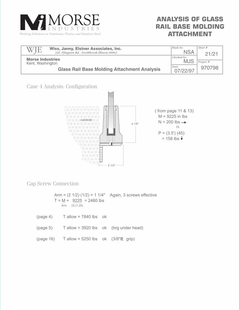
Case 4 Analysis: Configuration
Cap Screw Connection
( from page 11 & 13)
M = 9225 in lbs
N = 200 lbs
P = (3.5') (45)
= 158 lbs
Arm = (2 1/2) (1/2) = 1 1/4" Again, 3 screws effective
T = M + 9225 = 2460 lbs
(page 4)
(page 5)
(page 16)
T allow = 7840 lbs ok
T allow = 3920 lbs ok (brg under head)
T allow = 5250 lbs ok (3/8" grip)
4 1/8"DL
Arm (3) (1.25)
2 1/2"
ANALYSIS OF GLASS
RAIL BASE MOLDING
ATTACHMENT
WJE Wiss, Janny, Elstner Associates, Inc.
Morse Industries
Glass Rail Base Molding Attachment Analysis
NSA
MJS
21/21
97079807/22/97
Kent, Washington
330 Pfingsten Rd., Northbrook Illinois 60062
Made by: Sheet #
Project #
Checked by:
Date:
substrate