Embed Size (px)
DESCRIPTION
welding defects: chevron cracks
Citation preview
vvChevron Cracking" — A New Form of Hydrogen Cracking in Steel Weld Metals
Chevron cracking is a form of hydrogen induced cold cracking that can be eliminated through careful control of
the moisture content in basic type consumables
BY J. M. F. MOTA AND R. L. APPS
Introduction
Hydrogen induced cold cracking in the heat-affected zone has been one of the main problems in the welding of carbon manganese and low alloy steels. It has been gradually overcome by a better understanding of the phenomenon and its controlling parameters and, above all, by the introduction of better quality steels with lower carbon content. In fact, as the carbon content decreases towards 0.10% or less in the new steels, they tend to be free from the heat-affected zone cracking problem and the welding procedure is controlled by the need to avoid cracking in the weld metal (Ref. 1).
The relatively low carbon content and hardenability of most weld metals created a false sense of safety, i.e., that weld metals deposited with low hydrogen consumables would not be susceptible to hydrogen cracking. This feeling proved to be wrong in many cases. As the anti-hydrogen measures become less stringent, cracking has become more prevalent in the weld metal. Some forms of cracking are undoubtedly due to hydrogen while in other cases the mechanism is less certain.
One apparently new type of cracking was identified during the late 1960's and coincided with the then newly developed basic agglomerated fluxes for submerged arc welding (SAW) (Ref. 2, 3). Due to the parallel pattern of the defects it was designated "chevron cracking," "transverse 45 deg cracking" or "staircase cracking," but the first term is still
Paper presented at the 62nd AWS Annual Meeting held in Cleveland, Ohio, during April 6-10. 1981.
j M. F. MOTA is a Research Officer and R. L. APPS is Professor of Welding Technology, Cranfield Institute of Technology, Cranfield, Bedford. England.
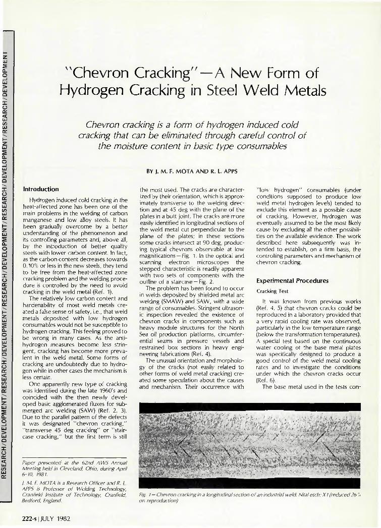
the most used. The cracks are characterized by their orientation, which is approximately transverse to the welding direction and at 45 deg with the plane of the plates in a butt joint. The cracks are more easily identified in longitudinal sections of the weld metal cut perpendicular to the plane of the plates; in these sections some cracks intersect at 90 deg, producing typical chevrons observable at low magnifications —Fig. 1. In the optical and scanning electron microscopes the stepped characteristic is readily apparent with two sets of components with the outline of a staircase —Fig. 2.
The problem has been found to occur in welds deposited by shielded metal arc welding (SMAW) and SAW, with a wide range of consumables. Stringent ultrasonic inspection revealed the existence of chevron cracks in components such as heavy module structures for the North Sea oil production platforms, circumferential seams in pressure vessels and restrained box sections in heavy engineering fabrications (Ref. 4).
The unusual orientation and morphology of the cracks (not easily related to other forms of weld metal cracking) created some speculation about the causes and mechanism. Their occurrence with
" low hydrogen" consumables (under conditions supposed to produce low weld metal hydrogen levels) tended to exclude this element as a possible cause of cracking. However, hydrogen was eventually assumed to be the most likely cause by excluding all the other possibilities on the available evidence. The work described here subsequently was intended to establish, on a firm basis, the controlling parameters and mechanism of chevron cracking.
Experimental Procedures
Cracking Test
It was known from previous works (Ref. 4, 5) that chevron cracks could be reproduced in a laboratory provided that a very rapid cooling rate was observed, particularly in the low temperature range (below the transformation temperatures). A special test based on the continuous water cooling of the base metal plates was specifically designed to produce a good control of the weld metal cooling rates and to investigate the conditions under which the chevron cracks occur (Ref. 6).
The base metal used in the tests con-
.
y . r ; •- •<•• - ' • • .
. . " a , ' .
K / ' S
p. * : W A
. • ? . • • • . £> • . . . "
\
Fig. I — Chevron cracking in a longitudinal section of an industrial weld. Nital etch; XI (reduced 26% on reproduction)
222-s | JULY 1982
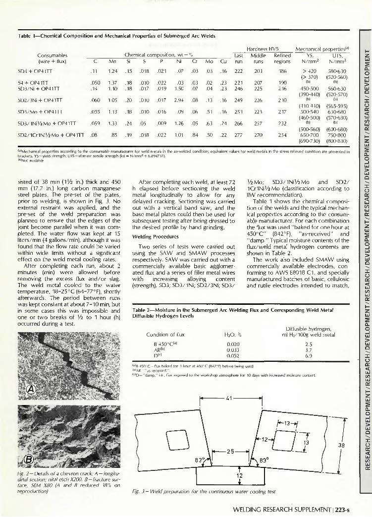
Table 1—Chemical Compositio
Consumables (wire + flux)
SD3 + OP4 1TT
S4 + OP4 ITT SD3/M + OP41TT
SD2/3Ni + OP41TT
SD3/MO + OP41TT
SD3/INi ' /2Mo + OP41TT
SD2/ !Cr1Ni'/2Mo + OP41TT
n and Mechanical Properties
C
.11
.050
.14
.060
.055
.059
.08
Mn
1.24
1.37 1.40
1.05
1.13
1.33
.85
of Submerged Arc Welds
Chemical composition, wt —
Si
.15
.18
.18
.20
.18
.24
.19
S
.018
.010
.017
.010
.010
.05
.018
P
.021
.022
.019
.017
.016
.009
.022
Ni
.07
.03 1.50
2.94
.09
1.26
1.01
w
Cr
.03
.03
.07
.08
.06
.05
.84
Mo
.03
.02
.04
.13
.51
.63
.50
Cu
.16
.23
.23
.16
.16
.24
.22
Last run
222
221 246
249
251
266
277
Hardness HV5 Middle Refined
runs
203
207 225
226
223
257
270
regions
186
190 216
210
217
232
254
Mechanical YS,
N/mm 2
> 4 2 0 (> 370)
(b)
450-500 (390-440)
(b)
(410-440) 500-540
(460-500) (b)
(500-560) 650-700
(690-730)
properties'3' UTS,
N/mm2
580-630 (520-560)
(b)
560-630 (520-570)
(b)
(565-595) 630-680
(570-630) (b)
(600-680) 750-800
(800-830)
<a,Mechanical properties according to the consumable manufacturer tor weld metals in the as-welded condit ion: equivalent values for weld metals in the stress relieved condition are presented in brackets. YS -y i e l d strength; UTS-u l t imate tensile strength (ksi = N / m m 2 + 6.894757). <b,Not available
sisted of 38 m m (IV2 in.) thick and 450 m m (17.7 in.) long carbon manganese steel plates. The pre-set of the plates, pr ior to we ld ing, is shown in Fig. 3. N o external restraint was appl ied, and the pre-set of the we ld preparat ion was planned to ensure that the edges of the joint become parallel w h e n it was c o m pleted. The wate r f l o w was kept at 15 l i ters/min (4 gal lons/min), a l though it was found that the f l o w rate cou ld be varied w i th in w i d e limits w i thou t a significant effect on the we ld metal cool ing rates.
Af ter comple t ing each run, about 2 minutes (min) w e r e a l lowed be fo re remov ing the excess flux a n d / o r slag. The we ld metal coo led to the water temperature , 1 8 - 2 5 ° C (64-77°F) , shortly af terwards. The per iod b e t w e e n runs was kept constant at about 7 -10 min, but in some cases this was impossible and one or t w o breaks of Vl to 1 hour (h) occur red dur ing a test.
Fig. 2 — Details of a chevron crack: A — longitudinal section; nital etch X200. B — fracture surface, SEM X80 (A and B reduced 38% on reproduction)
After comple t ing each w e l d , at least 72 h elapsed be fo re sectioning the w e l d metal longitudinally to al low for any delayed cracking. Sectioning was carried out w i th a vertical band saw, and the base metal plates could then be used for subsequent testing after being dressed to the desired prof i le by hand grinding.
Welding Procedures
T w o series of tests w e r e carried out using the SAW and S M A W processes respectively. S A W was carr ied out w i th a commercial ly available basic agglomerated flux and a series of filler metal wires w i t h increasing alloying content (strength): SD3; S D 3 / 1 N i ; S D 2 / 3 N i ; S D 3 /
I/2 M o ; S D 3 / 1 N i ' / 2 M o and S D 2 / I C M N i ' / i M o (classification according to IIW recommendat ion) .
Table 1 shows the chemical compos i t ion of the welds and the typical mechanical propert ies according to the consumable manufacturer . For each combinat ion the flux was used " bak ed for one hour at 4 5 0 ° C " (842CF), "as - rece ived" and " d a m p . " Typical moisture contents of the f l u x / w e l d metal hydrogen contents are shown in Table 2.
The w o r k also included S M A W using commercial ly available electrodes, con forming to A W S E8018 C 1 , and specially manufactured batches of basic, cellulosic and rutile electrodes in tended to match ,
Table 2—Moisture in the Submerged Arc Welding Flux and Corresponding Weld Metal Diffusible Hydrogen Levels
Condition of flux
B 450°C<a) AR<b» D ( 0
H 2 0, "o
0.020 0.033 0.052
Diffusible hydrogen, ml H2/100g weld metal
2.5 3.7 6.9
' • 'B 450 C - f l u x baked for 1 hour at 450 C (842 r) before being used (b)AR —"as received." ( c J D— "damp. " i.e.. flux exposed to the workshop atmosphere for 10 days wi th increased moisture content.
Fig. 3 - Weld preparation for the continuous water cooling test
W E L D I N G RESEARCH SUPPLEMENT I 223-s
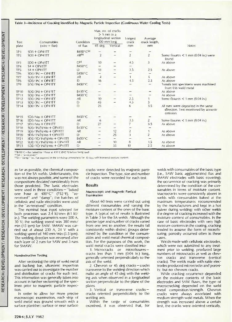
Table 3
Test plate
TP1 TP2
TP3 TP4 TP5 TP6 TP7 TP8 TP9
TPIO TP1 1 TP12 TP13 TPI4
TP15 TP16 TP17 TP18 TP19 TP20 TP2I TP22 TP23
—Incidence of Cracking Identified by Magnetic
Consumables Condition (wire + flux) of flux
SD3 + OP4 ITT B450°C(a)
SD3 + OP4 ITT AR<b»
SD3 + OP41TT D(c)
S4 + OP41TT B450°C S4 + OP41TT D SD3/1Ni-FOP41TT B450°C SD3/1Ni + OP41TT AR SD3/1Ni + OP4ITT D SD2/3Ni + OP4 ITT B450°C
SD2/3Ni + OP41TT B450°C SD2/3Ni + OP41TT B450°C SD2/3Ni + OP41TT AR SD2/3Ni + OP41TT D SD2/3Ni + OP41TT D
SD3/Mo + OP4 ITT B450°C SD3/Mo -1- OP41TT AR SD3/Mo + OP4 ITT D SD3/1Ni'/2Mo + OP41TT B450°C SD3/1Ni'/2Mo + OP41TT AR SD3/1Ni'/2Mo + OP41TT D SD2/1Cr1Ni'/2Mo + OP41TT B450°C SD2/1Cr1Ni'/2Mo + OP41TT AR SD2/1Cr1Ni'/2Mo + OP41TT D
Particle Inspection
Max. no. of cracks > 1 mm in a
longitudinal section 100
45 deg
— 2
10
-13
-4
16
—
--10 45 25
-6
27
-----—
n m long Vertical
— —
------—
----
----12 25
-10 33
Continuous
Longest crack mm
— 2
4.5
-3.5
— 1 4.5
—
— — 2.5 4.5 6
— 3.5 7
-2 3
-8
10
Water Cooling Tests)
Average crack length,
mm
-2
3
2.5
-1 2.5
—
--1 3 3.5
-2 3.5
-1 2
-1.5 2.5
Notes
Some fissures < 1 mm (0.04 in.) were found
As above
As above
As above As above Tensile test specimens were machined
from this weld metal As above As above Some fissures < 1 mm (0.04 in.)
All runs were deposited in the same direction. Test monitored by acoustic emission
Some fissures < 1 mm (0.04 in.) As above
As above As above
As above As above
(a)B450 C - flux baked for 1 hour at 450 C (842 F) before being used. l b ,AR — "as-received." ( c ) D - " d a m p , " i.e., flux exposed to the workshop atmosphere for 10 days wi th increased moisture content.
as far as possible, the chemical composition of the SA welds. Unfortunately, this was not always possible, and some of the compositions deviated considerably from those predicted. The basic electrodes were used in three conditions —"baked one hour at 400°C" (752°F), "as-received" and "damp"; the batches of cellulosic and rutile electrodes were used in the "as-received" condition.
The nominal heat input selected for both processes was 2.4 k)/mm (61 k)/ in.). The welding parameters were 500 A, 30 V; the welding speed was 380 m m / min (15 ipm) for SAW. SMAW was carried out at about 230 A, 24 V with a welding speed of 140 mm/min (5.5 ipm). The welding direction was reversed after each layer of 2 runs for SAW and 3 runs for SMAW.
Nondestructive Testing
After sectioning the strip of weld metal and backing bar, ultrasonic inspection was carried out to investigate the number and distribution of cracks for each test. This information was generally taken into account in further sectioning of the specimen prior to magnetic particle inspection.
In order to allow for more precise macroscopic examination, each strip of weld metal was ground smooth with a surface planisher; surface or near surface
cracks were detected by magnetic particle inspection. The type, size and number of cracks were recorded for each test.
Results
Macroscopic and Magnetic Partical Examination
About 60 tests were carried out using different consumables and varying the moisture content of the ones of the basic type. A typical set of results is illustrated in Table 3 for the SA welds. Although the precise type and number of cracks varied from one test to another, the results fall consistently within distinct groups determined by the condition of the consumables and weld metal chemical composition. For the purposes of this work, the weld metal cracks were classified into:
1. Microcracks or microfissures — cracks less than 1 mm (0.04 in.) long, generally oriented perpendicularly to the axis of the weld.
2. Chevron or 45 deg cracks-cracks transverse to the weiding direction which make an angle of 45 deg with the welding axis when observed in a longitudinal section perpendicular to the plane of the plates.
3. Vertical or transverse cracks — cracks oriented perpendicularly to the welding axis.
Within the range of consumables examined, it was observed that, for
welds with consumables of the basic type (i.e., SAW basic agglomerated flux and SMAW electrodes with basic covering), the occurrence of cracking was primarily determined by the condition of the consumables in terms of moisture content. Macrocracks were consistently absent in welds with consumables baked at the maximum temperatures recommended by the manufacturers and kept in a hot quiver during welding; with other welds the degree of cracking increased with the moisture content of consumables. In the case of basic electrodes with very high moisture contents in the coating, cracking tended to assume the form of microfissuring; porosity occurred often in these cases.
Welds made with cellulosic electrodes, which were not submitted to any treatment prior to welding, produced large numbers of microcracks as well as chevron cracks and transverse (vertical cracks). The welds made with rutile electrodes produced microcracks and porosity, but no chevron cracks.
While cracking occurrence depended on the moisture contents of the basic electrodes and SAW fluxes, the type of macrocracking depended on the weld metal composition/strength. Chevron cracks were always associated with medium strength weld metals. When the strength was increased above a certain limit, the cracks were oriented vertically,
224-s | JULY 1982

Fig. 4 —Staggered non-linked microcracks. A —first stage; B — intermediate stage. Nital etch; X200
i.e., perpendicular to the welding direction.
Metallographic Examination
Longitudinal sections from all specimens containing macrocracks were observed in the optical microscope with the objectives of establishing a relation between the morphology of the crack and the weld metal microstructure, and of comparing them with others in industrial samples. There were no major differences between the cracks observed in the industrial samples and in the laboratory tests; consequently, the results and comments below refer to both except where otherwise stated.
Chevron cracks were found to occur in both the as-deposited and reheated weld metal, showing a characteristic stair
case appearance with vertical and horizontal components —Fig. 2. The vertical components of the cracks in the as-deposited metal tended to occur predominantly in the pro-eutectoid ferrite (at the prior austenite grain boundaries), but often they propagated away from it or followed a different path.
Many examples were found of non-linked microcracks with a special arrangement very similar to the vertical components of the chevron cracks, Fig. 4A. In some cases there was an indication that these microcracks had started to link, but the process was not completed —Fig. 4B. In the longitudinal horizontal plane, i.e., in an orientation parallel to the plane of the plates, chevron cracks were found to be almost transverse to the welding direction and had the typical morphology illustrated in Fig. 5.
Vertical cracks (i.e., perpendicular to the axis of the weld or just slightly inclined—Fig. 6) were typical of the higher strength weld metals used in the laboratory tests. In some cases the cracks presented a staircase morphology reminiscent of the 45 deg cracks, but this was unusual. In general the cracks did not follow a typical path; they could be both inter- and transgranular, continuous or intermittent and sometimes branched.
Microcracks or microfissures such as shown in Fig. 7 could —with one exception—be easily found in all weld metal cracking tests. The exception consisted of SA welds with the flux baked 1 h at 450°C (842°F). The microfissures were randomly distributed through the longitudinal sections, but their density was reduced in the top runs and in the runs containing high numbers of macrocracks. Microfissuring was the typical form of cracking in weld metals deposited with rutile electrodes; in some cases microfissuring was found to be nucleated at a void. In general these weld metals did not develop macrocracks except for the most highly alloyed deposits.
Fractographic Examination
In the scanning electron microscope (SEM), at low magnifications, the staircase appearance of the chevron cracks was easily recognized — Fig. 2. After increasing the magnification, it was readily apparent that there were two distinct sets of components which could be observed in planes approximately perpendicular to each other. The vertical components presented mainly quasi-cleavage (Fig. 8), but some showed relatively smooth areas — Fig. 9 (the significance of which is discussed later in this paper). The origin of each vertical component was not always clear; in some cases, however, the components showed a pattern radiating from
-fv&VbiaizkiwHKL r
m!&
•
Fig. 5 —Chevron crack. Longitudinal section parallel to the plane of the plates. Nital etch; X200 (reduced 38% on reproduction)
Fig. 6— "Vertical crack" in a SAW deposit with Fig. 7—"Microfissures" in a SMAW deposit. SD3/1N 1/2 Mo wire. Nital etch; X80 (reduced Nital etch X20 (reduced 41% on reproduc-38",, on reproduction) tion)
WELDING RESEARCH SUPPLEMENT 1225-s

Fig. 8 - Chevron crack SEM: A - vertical component of a chevron crack; B — detail from A (reduced 41% on reproduction)
Fig. 9 — Chevron crack SEM: A — vertical component of a chevron crack with signs of exposure to high temperature; B — detail from A (reduced 41 % on reproduction)
the center where a void (pore or inclusion hole) could sometimes be found. The horizontal components showed essentially dimples —Fig. 10.
The fracture surface of the vertical cracks observed in the high strength weld metals consisted of areas of inter- and transgranular failure —Fig. 11. The mode of failure through the grains was quasi-cleavage. However, regions of dimples could be found linking areas of brittle failure.
Microfissures were observed for all weld metal compositions. The ones found in the medium strength weld metals presented a mode of failure similar to the vertical components of the chevron cracks, but tended to be bigger in size. Fissures occurring in the runs below the top one very often presented smooth regions, resembling those found in the chevron cracks as referred to above.
Carbon extraction replicas from the fracture surface of some chevron cracks were observed in the transmission electron microscope, after having examined the corresponding surfaces using the SEM. This work confirmed that the fracture surface of most cracks consisted of areas of quasi-cleavage alternating with areas of dimples with no evidence of thermal facets or grooves. These features were found, however, in a limited number of vertical components of chevron cracks which showed smooth areas unresolved in the SEM.
Discussion
When the present research program on chevron cracking was initiated, two different explanatory theories had just appeared (Ref. 4, 5). Insufficient evidence did not allow the controlling parameters of the phenomenon to be firmly established, leaving the field open to some controversy over the causes and mechanism. Keville's theory (Ref. 5) suggested that cracking resulted from a combination of hydrogen and stresses; this seemed to be supported by industrial evidence. However, the alternative presented by Tuliani could not simply be dismissed on the grounds that the features identified on the fracture surfaces (typical of exposure to high temperatures) were caused
-ry. Fig. 10 — Horizontal component of a chevron crack (reduced 38",, on reproduction)
by reheating on the deposition of subsequent runs of weld metal (Ref. 7).
Existing evidence pointed towards hydrogen as being the main factor controlling the occurrence of chevron cracking. Nonetheless, it was possible that some form of hot cracking could be involved. This possibility was investigated and rejected through the study of a wide range of chemical compositions and carrying out hot tensile tests on weld metals already studied for cracking susceptibility (Ref. 8). The influence of hydrogen on the cracking incidence was studied by using the SAW basic flux and the basic SMAW electrodes with controlled moisture contents, producing different hydrogen contents in the weld metal. In brief, it was intended to support the metallographic and fractographic evidence with extensive experimental results.
The cracking test designed by the authors was substantially more severe than the one ascribed to Tuliani (Ref. 4) and used in other works (Ref. 5, 9, 10). The use of continuous water cooling had the advantage of an easier control over the weld metal cooling rates. However, it was designed in a way that only the low temperature range of the weld metal cooling cycle (below the transformation temperatures) would be affected. In these circumstances the major effect would be on the retention of hydrogen.
Cracking tests results showed conclusively that hydrogen was the most important factor controlling the occurrence of chevron cracking and that the phenomenon must be due to a hydrogen induced cracking mechanism. This conclusion is based, primarily, on the fact that cracking can be entirely controlled by the moisture level in the consumables/hydrogen level in the weld metal. It was further substantiated by the fractographic examination which established a good correlation between the features observed on the vertical components of the chevron cracks, microfissures and the areas of brittle failure on the surface of hydrogen charged tensile specimens in similar weld metals.
The comparison between the fracture surfaces of chevron cracks and hydrogen
Fig. II- "Vertical crack" in a SAW deposit made withSD3/1Ni '/2 Mo wire (reduced 38% on reproduction)
226-s | JULY 1982
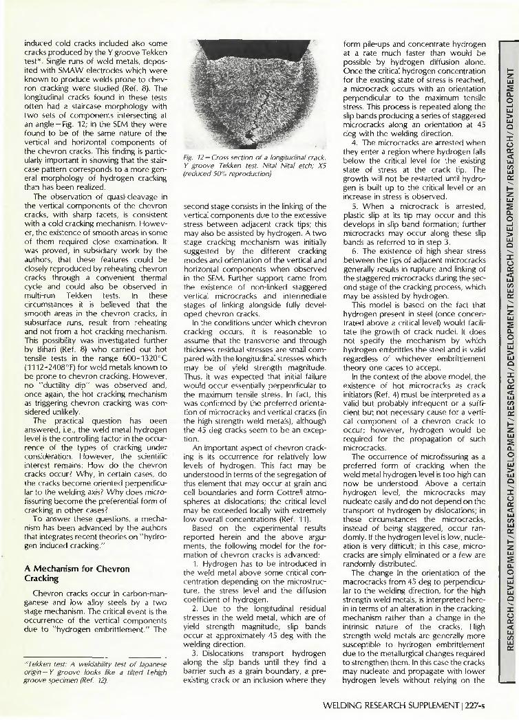
induced cold cracks included also some cracks produced by the Y groove Tekken test*. Single runs of weld metals, deposited with SMAW electrodes which were known to produce welds prone to chevron cracking were studied (Ref. 8). The longitudinal cracks found in these tests often had a staircase morphology with two sets of components intersecting at an angle —Fig. 12; in the SEM they were found to be of the same nature of the vertical and horizontal components of the chevron cracks. This finding is particularly important in showing that the staircase pattern corresponds to a more general morphology of hydrogen cracking than has been realized.
The observation of quasi-cleavage in the vertical components of the chevron cracks, with sharp facets, is consistent with a cold cracking mechanism. However, the existence of smooth areas in some of them required close examination. It was proved, in subsidiary work by the authors, that these features could be closely reproduced by reheating chevron cracks through a convenient thermal cycle and could also be observed in multi-run Tekken tests. In these circumstances it is believed that the smooth areas in the chevron cracks, in subsurface runs, result from reheating and not from a hot cracking mechanism. This possibility was investigated further by Bihari (Ref. 8) who carried out hot tensile tests in the range 600-1320°C (1112-2408°F) for weld metals known to be prone to chevron cracking. However, no "ductility dip" was observed and, once again, the hot cracking mechanism as triggering chevron cracking was considered unlikely.
The practical question has been answered, i.e., the weld metal hydrogen level is the controlling factor in the occurrence of the types of cracking under consideration. However, the scientific interest remains: How do the chevron cracks occur? Why, in certain cases, do the cracks become oriented perpendicular to the welding axis? Why does microfissuring become the preferential form of cracking in other cases?
To answer these questions, a mechanism has been advanced by the authors that integrates recent theories on "hydrogen induced cracking."
A Mechanism for Chevron Cracking
Chevron cracks occur in carbon-manganese and low alloy steels by a two stage mechanism. The critical event is the occurrence of the vertical components due to "hydrogen embrittlement." The
"Tekken test: A weldability test of lapanese origin - Y groove looks like a tilted Lehigh groove specimen (Ref. 12).
Fig. 12 — Cross section of a longitudinal crack. Y groove Tekken test. Nital Nital etch; X5 (reduced 50% reproduction)
second stage consists in the linking of the vertical components due to the excessive stress between adjacent crack tips; this may also be assisted by hydrogen. A two stage cracking mechanism was initially suggested by the different cracking modes and orientation of the vertical and horizontal components when observed in the SEM. Further support came from the existence of non-linked staggered vertical microcracks and intermediate stages of linking alongside fully developed chevron cracks.
In the conditions under which chevron cracking occurs, it is reasonable to assume that the transverse and through thickness residual stresses are small compared with the longitudinal stresses which may be of yield strength magnitude. Thus, it was expected that initial failure would occur essentially perpendicular to the maximum tensile stress. In fact, this was confirmed by the preferred orientation of microcracks and vertical cracks (in the high strength weld metals), although the 45 deg cracks seem to be an exception.
An important aspect of chevron cracking is its occurrence for relatively low levels of hydrogen. This fact may be understood in terms of the segregation of this element that may occur at grain and cell boundaries and form Cottrell atmospheres at dislocations; the critical level may be exceeded locally with extremely low overall concentrations (Ref. 11).
Based on the experimental results reported herein and the above arguments, the following model for the formation of chevron cracks is advanced:
1. Hydrogen has to be introduced in the weld metal above some critical concentration depending on the microstructure, the stress level and the diffusion coefficient of hydrogen.
2. Due to the longitudinal residual stresses in the weld metal, which are of yield strength magnitude, slip bands occur at approximately 45 deg with the welding direction.
3. Dislocations transport hydrogen along the slip bands until they find a barrier such as a grain boundary, a preexisting crack or an inclusion where they
form pile-ups and concentrate hydrogen at a rate much faster than would be possible by hydrogen diffusion alone. Once the critical hydrogen concentration for the existing state of stress is reached, a microcrack occurs with an orientation perpendicular to the maximum tensile stress. This process is repeated along the slip bands producing a series of staggered microcracks along an orientation at 45 deg with the welding direction.
4. The microcracks are arrested when they enter a region where hydrogen falls below the critical level for the existing state of stress at the crack tip. The growth will not be restarted until hydrogen is built up to the critical level or an increase in stress is observed.
5. When a microcrack is arrested, plastic slip at its tip may occur and this develops in slip band formation; further microcracks may occur along these slip bands as referred to in step 3.
6. The existence of high shear stress between the tips of adjacent microcracks generally results in rupture and linking of the staggered microcracks during the second stage of the cracking process, which may be assisted by hydrogen.
This model is based on the fact that hydrogen present in steel (once concentrated above a critical level) would facilitate the growth of crack nuclei. It does not specify the mechanism by which hydrogen embrittles the steel and is valid regardless of whichever embrittlement theory one cares to accept.
In the context of the above model, the existence of hot microcracks as crack initiators (Ref. 4) must be interpreted as a valid but probably infrequent or a sufficient but not necessary cause for a vertical component of a chevron crack to occur; however, hydrogen would be required for the propagation of such microcracks.
The occurrence of microfissuring as a preferred form of cracking when the weld metal hydrogen level is too high can now be understood. Above a certain hydrogen level, the microcracks may nucleate easily and do not depend on the transport of hydrogen by dislocations; in these circumstances the microcracks, instead of being staggered, occur randomly. If the hydrogen level is low, nucleation is very difficult; in this case, microcracks are simply eliminated or a few are randomly distributed.
The change in the orientation of the macrocracks from 45 deg to perpendicular to the welding direction, for the high strength weld metals, is interpreted herein in terms of an alteration in the cracking mechanism rather than a change in the intrinsic nature of the cracks. High strength weld metals are generally more susceptible to hydrogen embrittlement due to the metallurgical changes required to strengthen them. In this case the cracks may nucleate and propagate with lower hydrogen levels without relying on the
WELDING RESEARCH SUPPLEMENT I 227-s

transport of that element by dislocations along 45 deg slip bands. A second reason may be the relative weakening of the grain boundaries as the matrix is strengthened, offering an easy, preferential path for the crack growth. In these circumstances the vertical cracks grow continuously through the material, although the process may be discontinuous in time as is typical of hydrogen cracking.
Conclusions
of 1. Chevron cracking is a type hydrogen induced cold cracking.
2. Chevron cracking can be eliminated simply by a careful control of the moisture content in the consumables of the basic type.
3. Microfissuring may become the preferential form of cracking, if the hydrogen level is too low or too high.
4. The orientation of the transverse, hydrogen induced cracks in the weld metal depends primarily on the weld metal composition/strength; chevron cracks are typical of medium strength weld metals.
5. A two-stage cracking mechanism was proposed to explain the occurrence and orientation of the chevron cracks.
References
1. Dolby, R. E. 1977. The weldability of low carbon structural steels. Welding Institute Research Bulletin 18(8):209-216.
2. Thomas, S. N. C. 1969. The implications of weld cracking in practice. Metal Construction 7(2): 142.
3. Cotton, H. C. Ibid. 4. Tuliani, S. S. 1976. A metallographic study
of chevron cracks in submerged arc weld metals. Welding Research International 6(6):19-45.
5. Keville, B. R. 1976. An investigation to determine the mechanism involved in the formation and propagation of chevron cracks
in submerged arc weldments. Welding Research International 6(6):47-66.
6. Mota, |. M. F.; Apps, R. L; and ]ubb, ]. E. M. 1978. Chevron cracking in manual metal arc welding. Proc. Conf. on Trends in Steels and Consumables for Welding. Welding Institute, paper no. 18.
7. Farrar, R. A. 1977. The nature of chevron cracking in submerged arc weld metals. Welding Research International 7(2):85-88.
8. Bihari, L. M. 1976. Relation of hydrogen cracking and high temperature ductility to chevron cracking in steel weld metal. M.Sc. thesis, Cranfield Institute of Technology.
9. Wright, V. S., and Davison, I. T. 1978. Chevron cracking in submerged arc welds, Proc. Conf. on Trends in Steels and Consumables for Welding. Welding Institute, paper No. 38.
10. Chew, B., Private Communication. 11. Savage, W. F., et al. 1978. Hydrogen
induced cracking in HY-130 steel weldments. Welding lournal 57(4): 118-s to 126-s.
12. Vasudevan, R.; Stout, R. D.; and Pense, A. W. 1981. Hydrogen-assisted cracking in HSLA pipeline steels. Welding journal 60(9): 156-s.
WRC Bulletin 275 February, 1982
The Use of Quenched and Tempered 2 - l / 4 C r - l M o Steel for Thick Wall Reactor Vessels in Petroleum Refinery Processes: An Interpretive Review of 25 Years of Research and Application by W. E. Erwin and J. G. Kerr
This WRC Bulletin focuses on the evolution of modern hydroprocessing reactors fabricated f rom quenched and tempered 2 - l / 4 C r - l M o steel. It reviews and summarizes approximately 25 years of industry development and application of 2 - l / 4 C r - l M o steel in hydroprocessing reactors. Some discussion of ongoing research and needs for future research are identif ied.
Publication of this Bulletin was sponsored by the Subcommit tee on Thermal and Mechanical Effects of the Pressure Vessel Research Commit tee of the Welding Research Council.
The price of WRC Bulletin 275 is $13.00 per copy, plus $3.00 for postage and handling. Orders should be sent with payment to the Welding Research Council, 345 E. 47th St., New York, NY 10017.
WRC Bulletin 276 April, 1982
A Summary and Critical Evaluation of Stress Intensity Factor Solutions of Corner Cracks at the Edge of a Hole by R. L. Cloud and S. S. Palusamy
When the probable initial flaw size and the crack growth rate for a given material are known, crack growth behavior is calculable on the basis of loading and stress profile through the use of f racture mechanics and parameters. This report summarizes and critically evaluates Stress Intensity Factor (SIF) solutions to corner cracks at the edge of a hole.
Based on recommendations f rom this study, a compilation of SIF values for nozzle cracks is proposed.
Publication of this paper was sponsored by the Task Group on Nozzle Crack Growth of the Subcommittee on Reinforced Openings and External Loadings of the Pressure Vessel Research Commit tee of the Welding Research Council.
The price of WRC Bulletin 276 is $11.50 per copy, plus $3.00 for postage and handling. Orders should be sent with payment to the Welding Research Council, 345 E. 47th St., New York, NY 10017.
228-s|JULY 1982