Embed Size (px)
Citation preview

M.S.RogersM.S.Rogers
T E
C H
N O
L O
G Y
Copyright © 2003 TWI Ltd
SWI 3.2
Senior Welding InspectionResidual Stress and Distortion
Course Reference WIS 10

M.S.RogersM.S.Rogers
T E
C H
N O
L O
G Y
Copyright © 2003 TWI Ltd
SWI 3.2
Normal StressStress arising from a force perpendicular to the
cross sectional area
Compression
Tension
StressesStresses

M.S.RogersM.S.Rogers
T E
C H
N O
L O
G Y
Copyright © 2003 TWI Ltd
SWI 3.2
Shear StressStress arising from forces which are parallel to, and lie in the plane of the cross sectional area.
Shear Stress
StressesStresses

M.S.RogersM.S.Rogers
T E
C H
N O
L O
G Y
Copyright © 2003 TWI Ltd
SWI 3.2
Hoop StressStress acting circumferentially around a pipe due to
internal pressure.
Hoop Stress
StressesStresses

M.S.RogersM.S.Rogers
T E
C H
N O
L O
G Y
Copyright © 2003 TWI Ltd
SWI 3.2
Metal contract during solidification and subsequent
cooling.
If this contraction is prevented or inhibited
residual stress will develop.
The tendency to develop residual stresses increases
when the heating and cooling is localised.
Welding is very localised heating and the presence of
liquid and solid metal in contact can be expected to
induce very high levels of residual stresses.
Residual StressResidual Stress

M.S.RogersM.S.Rogers
T E
C H
N O
L O
G Y
Copyright © 2003 TWI Ltd
SWI 3.2
Residual stresses are very difficult to measure with
any real accuracy.
Residual stresses are self balancing internal forces
and not stresses induced whilst applying external
load
Stresses are more concentrated at the surface of the
component.
The removal of residual stresses is termed stress
relieving.
Residual StressResidual Stress
M.S.RogersM.S.Rogers
T E
C H
N O
L O
G Y
Copyright © 2003 TWI Ltd
SWI 3.2
Longitudinal
Along the weld – longitudinal residual stresses
Transverse
Across the weld – transverse residual stresses
Short Transverse
Through the weld – short transverse residual stresses
Residual stresses occur in welds in the following directions
Residual StressResidual Stress

M.S.RogersM.S.Rogers
T E
C H
N O
L O
G Y
Copyright © 2003 TWI Ltd
SWI 3.2
DistortionDistortionDistortion is a very complex matter more than 20 factors
influence its magnitude and for this reason it is very difficult to predict its exact amount of distortion that may occur

M.S.RogersM.S.Rogers
T E
C H
N O
L O
G Y
Copyright © 2003 TWI Ltd
SWI 3.2
Factors which affect distortion are: material properties, welding process, welding variables, the amount of restraint,
joint geometry and the welding procedure
DistortionDistortion

M.S.RogersM.S.Rogers
T E
C H
N O
L O
G Y
Copyright © 2003 TWI Ltd
SWI 3.2
Fit-up is very important to minimise distortion, fit-up must be even and uniform to ensure constant shrinkage along the
joint
DistortionDistortion

M.S.RogersM.S.Rogers
T E
C H
N O
L O
G Y
Copyright © 2003 TWI Ltd
SWI 3.2
A mechanised welding process is preferable to a manual process because its consistent operation allows for better
distortion control. The required volume of weld metal should be deposited in the shortest time to minimise heat input
DistortionDistortion
M.S.RogersM.S.Rogers
T E
C H
N O
L O
G Y
Copyright © 2003 TWI Ltd
SWI 3.2
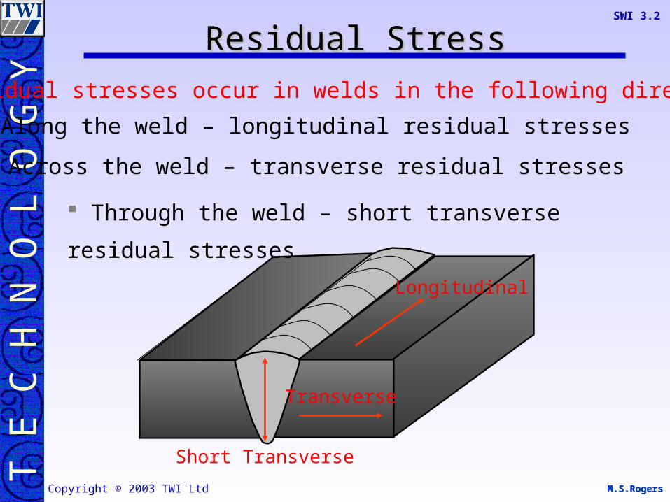
The shorter the welding time the less heat is transmitted in to the material and less distortion will occur. Keep welding times down by carefully selecting the welding process,
electrode type and size, welding current and travel speed
DistortionDistortion
M.S.RogersM.S.Rogers
T E
C H
N O
L O
G Y
Copyright © 2003 TWI Ltd
SWI 3.2
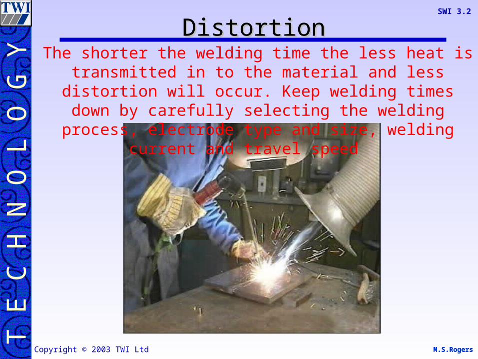
Longitudinal shrinkage/distortion
DistortionDistortion
M.S.RogersM.S.Rogers
T E
C H
N O
L O
G Y
Copyright © 2003 TWI Ltd
SWI 3.2
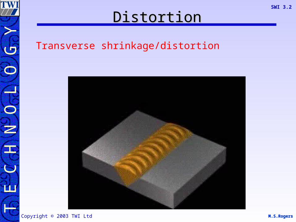
Transverse shrinkage/distortion
DistortionDistortion

M.S.RogersM.S.Rogers
T E
C H
N O
L O
G Y
Copyright © 2003 TWI Ltd
SWI 3.2
Angular distortion: weld metal contraction transverse
DistortionDistortion

M.S.RogersM.S.Rogers
T E
C H
N O
L O
G Y
Copyright © 2003 TWI Ltd
SWI 3.2
Angular distortion: weld metal contraction transverse
DistortionDistortion
M.S.RogersM.S.Rogers
T E
C H
N O
L O
G Y
Copyright © 2003 TWI Ltd
SWI 3.2
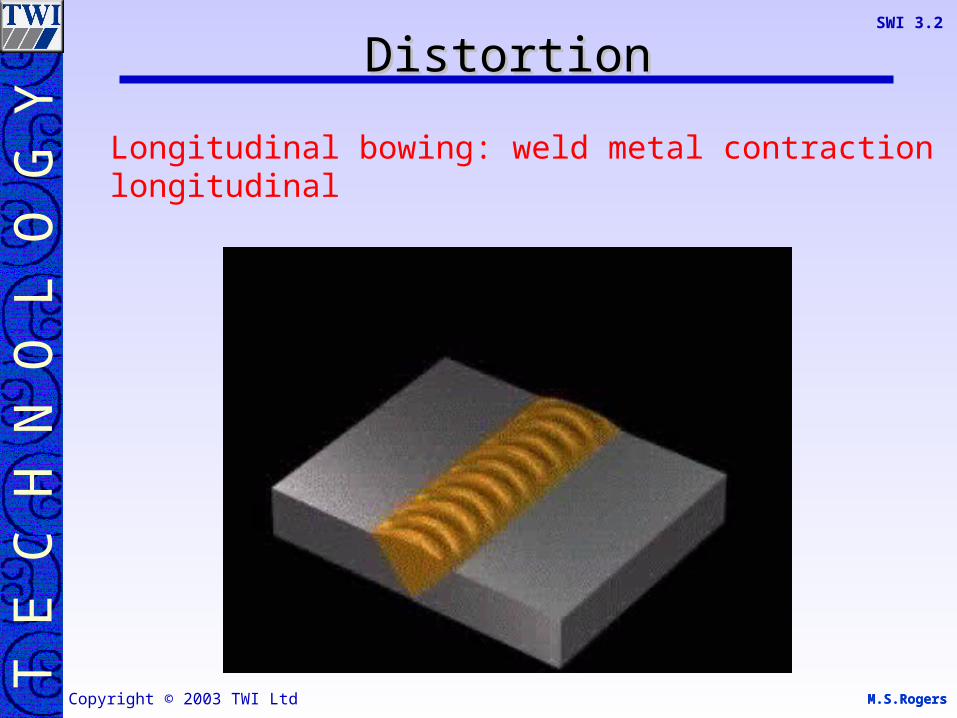
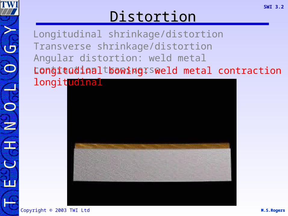
Longitudinal bowing: weld metal contraction longitudinal
DistortionDistortion

M.S.RogersM.S.Rogers
T E
C H
N O
L O
G Y
Copyright © 2003 TWI Ltd
SWI 3.2
Angular distortion: weld metal contraction transverse Longitudinal bowing: weld metal contraction longitudinal
Longitudinal shrinkage/distortion Transverse shrinkage/distortion
DistortionDistortion

M.S.RogersM.S.Rogers
T E
C H
N O
L O
G Y
Copyright © 2003 TWI Ltd
SWI 3.2
Angular distortion: weld metal contraction transverse Longitudinal bowing: weld metal contraction longitudinal
Longitudinal shrinkage/distortion Transverse shrinkage/distortion
DistortionDistortion

M.S.RogersM.S.Rogers
T E
C H
N O
L O
G Y
Copyright © 2003 TWI Ltd
SWI 3.2
Angular distortion: weld metal contraction transverse Longitudinal bowing: weld metal contraction longitudinal
Longitudinal shrinkage/distortion Transverse shrinkage/distortion
DistortionDistortion
M.S.RogersM.S.Rogers
T E
C H
N O
L O
G Y
Copyright © 2003 TWI Ltd
SWI 3.2
Angular distortion: weld metal contraction transverse Longitudinal bowing: weld metal contraction longitudinal
Longitudinal shrinkage/distortion Transverse shrinkage/distortion
DistortionDistortion

M.S.RogersM.S.Rogers
T E
C H
N O
L O
G Y
Copyright © 2003 TWI Ltd
SWI 3.2
Angular Distortion
Bowing Distortion Longitudinal Distortion
Transverse Distortion
DistortionDistortion

M.S.RogersM.S.Rogers
T E
C H
N O
L O
G Y
Copyright © 2003 TWI Ltd
SWI 3.2
Distortion will occur in all welded joints if the material
are free to move i.e. not restrained
Restrained materials result in low distortion but high
residual stress
More than one type of distortion may occur at one time
Highly restrained joints also have a higher crack
tendency to joints of a low restraint
The action of residual in welded joints is to cause
distortion
DistortionDistortion

M.S.RogersM.S.Rogers
T E
C H
N O
L O
G Y
Copyright © 2003 TWI Ltd
SWI 3.2
Material properties and condition
Heat input
The amount of restrain
The amount of weld metal deposited
Factors which affect distortion
DistortionDistortion

M.S.RogersM.S.Rogers
T E
C H
N O
L O
G Y
Copyright © 2003 TWI Ltd
SWI 3.2
The following movements can be detected in a simple butt weld1.Contraction in the weld metal along the welds length2.Bowing – due to the greater volume of weld metal at the top
of the weld3.Peaking due to the V angle4.Ripple (in sheet) away from the weld5.Contraction in the weld metal transverse to the weld, angular
distortion
5
34
3
12
DistortionDistortion

M.S.RogersM.S.Rogers
T E
C H
N O
L O
G Y
Copyright © 2003 TWI Ltd
SWI 3.2
The used of a different joint design
Control of distortion my be achieved in on of the following way
DistortionDistortion

M.S.RogersM.S.Rogers
T E
C H
N O
L O
G Y
Copyright © 2003 TWI Ltd
SWI 3.2
The volume of weld metal in a joint will affect the amount of local expansion and contraction, hence the more weld deposited the higher amount of distortion
Preparation angle 60o
Preparation angle 40o
Preparation angle 0o
DistortionDistortion

M.S.RogersM.S.Rogers
T E
C H
N O
L O
G Y
Copyright © 2003 TWI Ltd
SWI 3.2
The used of a different joint design
Offsetting the joints to be welded – so that the metal distorts into the required position.
Control of distortion my be achieved in on of the following way
DistortionDistortion

M.S.RogersM.S.Rogers
T E
C H
N O
L O
G Y
Copyright © 2003 TWI Ltd
SWI 3.2
Offsetting:The amount of offsetting required is generally a function of trail and error
DistortionDistortion

M.S.RogersM.S.Rogers
T E
C H
N O
L O
G Y
Copyright © 2003 TWI Ltd
SWI 3.2
The used of a different joint design
Offsetting the joints to be welded – so that the metal distorts into the required position.
The use of a balanced welding technique
Control of distortion my be achieved in on of the following way
DistortionDistortion

M.S.RogersM.S.Rogers
T E
C H
N O
L O
G Y
Copyright © 2003 TWI Ltd
SWI 3.2
Back-skip welding technique
Back-step welding technique
1. 2. 3. 4. 5. 6.
1. 2. 3. 6.4. 5.
DistortionDistortion

M.S.RogersM.S.Rogers
T E
C H
N O
L O
G Y
Copyright © 2003 TWI Ltd
SWI 3.2
The used of a different joint design
Presetting the joints to be welded – so that the metal distorts into the required position.
The use of a balanced welding technique
The use of clamps, jigs and fixtures.
Control of distortion my be achieved in on of the following way
DistortionDistortion
M.S.RogersM.S.Rogers
T E
C H
N O
L O
G Y
Copyright © 2003 TWI Ltd
SWI 3.2
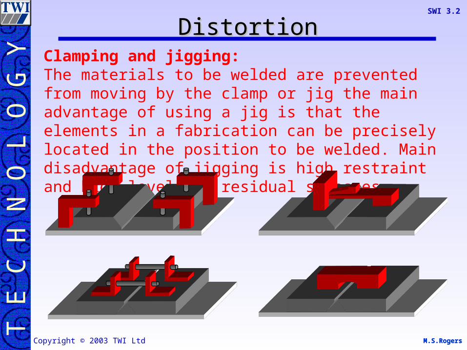
Clamping and jigging:The materials to be welded are prevented from moving by the clamp or jig the main advantage of using a jig is that the elements in a fabrication can be precisely located in the position to be welded. Main disadvantage of jigging is high restraint and high levels of residual stresses.
DistortionDistortion
M.S.RogersM.S.Rogers
T E
C H
N O
L O
G Y
Copyright © 2003 TWI Ltd
SWI 3.2
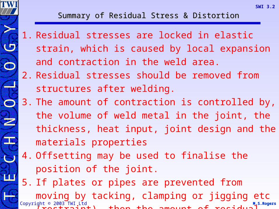
1. Residual stresses are locked in elastic strain, which is
caused by local expansion and contraction in the weld
area.
2. Residual stresses should be removed from structures
after welding.
3. The amount of contraction is controlled by, the volume of
weld metal in the joint, the thickness, heat input, joint
design and the materials properties
4. Offsetting may be used to finalise the position of the joint.
5. If plates or pipes are prevented from moving by tacking,
clamping or jigging etc (restraint), then the amount of
residual stresses that remain will be higher.
Summary of Residual Stress & DistortionSummary of Residual Stress & Distortion

M.S.RogersM.S.Rogers
T E
C H
N O
L O
G Y
Copyright © 2003 TWI Ltd
SWI 3.2
6. The movement caused by welding related stresses is
called distortion.
7. The directions of contractional stresses and distortion is
very complex, as is the amount and type of final distortion,
however we can say that there are three directions:
a. Longitudinal b. Transverse c.Short transverse
8. A high percentage of residual stresses can be removed by
heat treatments.
9. The peening of weld faces will only redistribute the
residual stress, and place the weld face in compression.
Summary of Residual Stress & DistortionSummary of Residual Stress & Distortion

M.S.RogersM.S.Rogers
T E
C H
N O
L O
G Y
Copyright © 2003 TWI Ltd
SWI 3.2
Any QuestionsAny Questions
M.S.RogersCopyright © 2003 TWI Ltd
M.S.RogersM.S.Rogers
T E
C H
N O
L O
G Y
Copyright © 2003 TWI Ltd
SWI 3.2
QU 1. What causes residual stress in welds?
QU 2. State three directions which residual stresses form in a weld.
QU 3. Give four methods of controlling distortion.
QU 4. Sketch two balanced welding techniques.
QuestionsQuestions
QU 5. State four factors which affect distortion.


![Sress and Anxiety Self Help[1]](https://img.pdfslide.us/doc/110x75/577cda321a28ab9e78a50c28/sress-and-anxiety-self-help1.jpg)