Embed Size (px)
Citation preview

Wiring and Drawing Diagrams for:
Bosch Heatronic 4000 Controls
Applications Manual
BAC net is a r egi ste red trade mar k o f A SHR AE. ASH RAE does not en dorse, ap prove or tes t products for co mpliance with A SHR AE sta ndards . C ompliance of listed products to the r equirements of ASH RAE St andard 135 is the r esp ons ibility of B ACn et Internationa l ( BI) . BTL is a r egiste red trade mar k of B I.
USC
®

2 | Bosch Heatronic 4000 Controls Applications Manual
Bosch Thermotechnology Corp.Data subject to change
Applications Manual Bosch Heatronic 4000 Controls | 3
Bosch Thermotechnology Corp. Data subject to change
Table of Contents
1 Introduction 4
2 Controls Description & Specifications 5
2.1 Brief description 5
2.2 Heatronic 4000 Outdoor Sensor 6
2.3 Heatronic 4000 Universal Sensor 7
3 Applications 8
3.1 Common Boiler Piping/Wiring 8
3.2 Boiler Connections 9
3.3 Application 1 10
3.4 Application 2 12
3.5 Application 3 14
3.6 Application 4 16
3.7 Application 5 18
3.8 Application 6 20
4 Burner Wiring Diagrams 22
4.1 Riello RS Modulating Burner Wiring: 22
4.2 Riello Dual Fuel Burner (2 Stage Oil & Modulating Gas) Wiring 23
4.3 Becket CG Burner Wiring: 24
4.4 Power Flame Burner Wiring: 25
4.5 Riello RS Lo/Hi/Lo Burner Wiring: 26
5 Recommended Specifications 27
4 | Bosch Heatronic 4000 Controls Applications Manual
Bosch Thermotechnology Corp.Data subject to change
1 Introduction
This manual is intended to address some of the many applications that are possible using the Bosch Heatronic 4000 control. The diagrams in this manual are for reference use by code officials, designers and licensed installers. It is expected that installers have adequate knowledge of national and local codes, as well as accepted industry practices, and are trained on equipment, procedures, and applications involved. Drawings are not to scale. Auxiliary equipment depicted in this manual does not necessarily represent any one particular manufacturer or specific model number. There are a wide variety of techniques, practices and piping arrangements possible with hydronic heating systems and it is the responsibility of the system engineer or the installing contractor to determine which of these is best suited for a specific application. Information for wiring of burners can be found in section 4 of this manual. Refer to control Installation Manual for additional detailed information. Should you encounter an application that is not covered in this manual or have questions regarding any of its content, we encourage you to contact us here at Bosch Thermotechnology Corp. Bosch Thermotechnology Corp. reserves the right to make changes without notice due to continuing engineering and technological improvements.
Applications Manual Bosch Heatronic 4000 Controls | 5
Bosch Thermotechnology Corp. Data subject to change
2 Controls Description & Specifications
2.1 Brief description
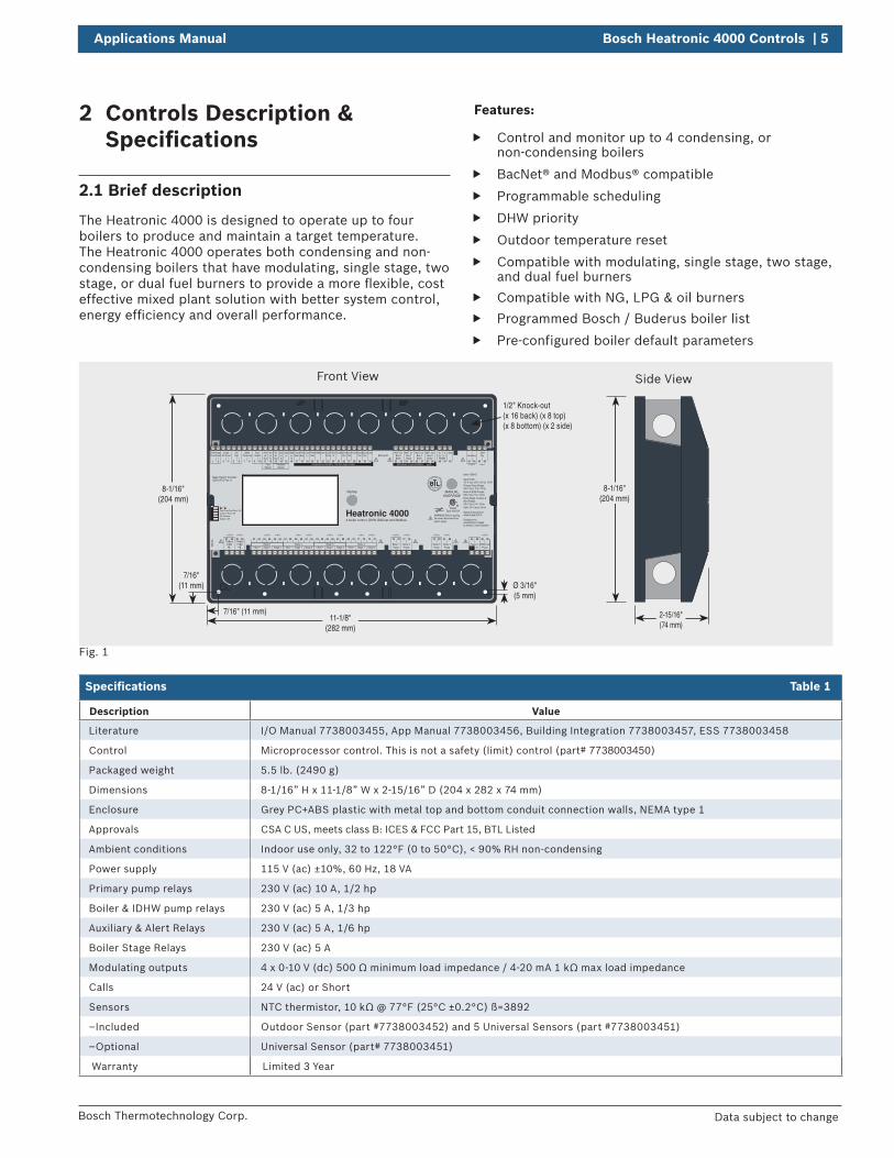
The Heatronic 4000 is designed to operate up to four boilers to produce and maintain a target temperature. The Heatronic 4000 operates both condensing and non-condensing boilers that have modulating, single stage, two stage, or dual fuel burners to provide a more flexible, cost effective mixed plant solution with better system control, energy efficiency and overall performance.
Fig. 1
Specifications Table 1
Description Value
Literature I/O Manual 7738003455, App Manual 7738003456, Building Integration 7738003457, ESS 7738003458
Control Microprocessor control. This is not a safety (limit) control (part# 7738003450)
Packaged weight 5.5 lb. (2490 g)
Dimensions 8-1/16” H x 11-1/8” W x 2-15/16” D (204 x 282 x 74 mm)
Enclosure Grey PC+ABS plastic with metal top and bottom conduit connection walls, NEMA type 1
Approvals CSA C US, meets class B: ICES & FCC Part 15, BTL Listed
Ambient conditions Indoor use only, 32 to 122°F (0 to 50°C), < 90% RH non-condensing
Power supply 115 V (ac) ±10%, 60 Hz, 18 VA
Primary pump relays 230 V (ac) 10 A, 1/2 hp
Boiler & IDHW pump relays 230 V (ac) 5 A, 1/3 hp
Auxiliary & Alert Relays 230 V (ac) 5 A, 1/6 hp
Boiler Stage Relays 230 V (ac) 5 A
Modulating outputs 4 x 0-10 V (dc) 500 Ω minimum load impedance / 4-20 mA 1 kΩ max load impedance
Calls 24 V (ac) or Short
Sensors NTC thermistor, 10 kΩ @ 77°F (25°C ±0.2°C) ß=3892
–Included Outdoor Sensor (part #7738003452) and 5 Universal Sensors (part #7738003451)
–Optional Universal Sensor (part# 7738003451)
Warranty Limited 3 Year
Features:
f Control and monitor up to 4 condensing, or non-condensing boilers
f BacNet® and Modbus® compatible
f Programmable scheduling
f DHW priority
f Outdoor temperature reset
f Compatible with modulating, single stage, two stage, and dual fuel burners
f Compatible with NG, LPG & oil burners
f Programmed Bosch / Buderus boiler list
f Pre-configured boiler default parameters
8-1/16"(204 mm)
7/16" (11 mm)
CL7/16"
(11 mm) Ø 3/16" (5 mm)
1/2" Knock-out (x 16 back) (x 8 top)(x 8 bottom) (x 2 side)
12
34
5
Temperature Sensors - Do Not Apply Power tekmarNet Communication
C3C2C0 C1
H6106A Boiler 1
75 76
PumpBoiler 2
77 78
PumpBoiler 3
79 80
PumpBoiler 4
81 82
PumpPower InL N
45 46
Auxiliary
43 44
Pump
47 48
P1Pump
Primary Primary49 50
P2
85 8683 84
20V
11
dc5Vdc
Out In Out In In
Vdc
14
(+) (+)Gnd
15
(-) (-)mA
12 13
(+)EMS
16 17
PrimSup
18
Com
19
PrimRet
BoilIn
20
DHW
21
Com
22 23 24 25
Boil 1Out
26
Boil 2Out
27
ComCom
28
Com
31
Boil 3Out
29
Boil 4Out
30
tN4
32 33
Bus btN4
34 35
Bus 1tN4
36 37
Bus 2tN4
38 39
Bus 3Boiler Boiler Boiler Boiler
PrimPump
1 2
Comb
3 4
Air ProofCH
5 6
CallDHW
7 8
Tank CallFuel
9 10
Switch
FlowSensor
PressureSensor
B A
40 41
BACnet IPRS485
42
Gnd
Prim Pump Flow Proof / OffComb Air Proof / OffOff / ExerciseSetback / Off
51 52
ModBoiler 1
53 54
Stage 1 Stage 2
55 56
+ - Mod Stage 1 Stage 2+ - Mod Stage 1 Stage 2+ - Mod Stage 1 Stage 2+ -
57 58
Boiler 2
59 60 61 62 63 64
Boiler 3
65 66 67 68 69 70
Boiler 4
71 72 73 74
WARNING! Before openingthe cover disconnect frompower supply
Meets Class B: CanadianICES & FCC Part 15
4 boiler control, DHW, BACnet and Modbus
MANUALOVERRIDE
Home
Outdoor
ComFlue
AlertDryFlow Proof
TankDHWPump
(+) (–)
Heatronic 4000158033
Type 1056-XX
tektra 1056-02
Designed and assembled in Canadaby tekmar Control Systems
Signal wiring must be rated at least 300 V.
Input Power: 115 V (ac) ±10%, 60 Hz, 18 VAPrimary Pump Relays: 230 V (ac), 10 A, 1/2 hpBoiler & DHW Pumps: 230 V (ac), 5 A, 1/3 hpBoiler Stage, Auxiliary & Alert Relays: 230 V (ac), 5 A, 1/6 hpCalls: 24 V (ac) or Short
11-1/8" (282 mm)
Side ViewFront View
2-15/16" (74 mm)
8-1/16"(204 mm)
6 | Bosch Heatronic 4000 Controls Applications Manual
Bosch Thermotechnology Corp.Data subject to change
2.2 Heatronic 4000 Outdoor Sensor
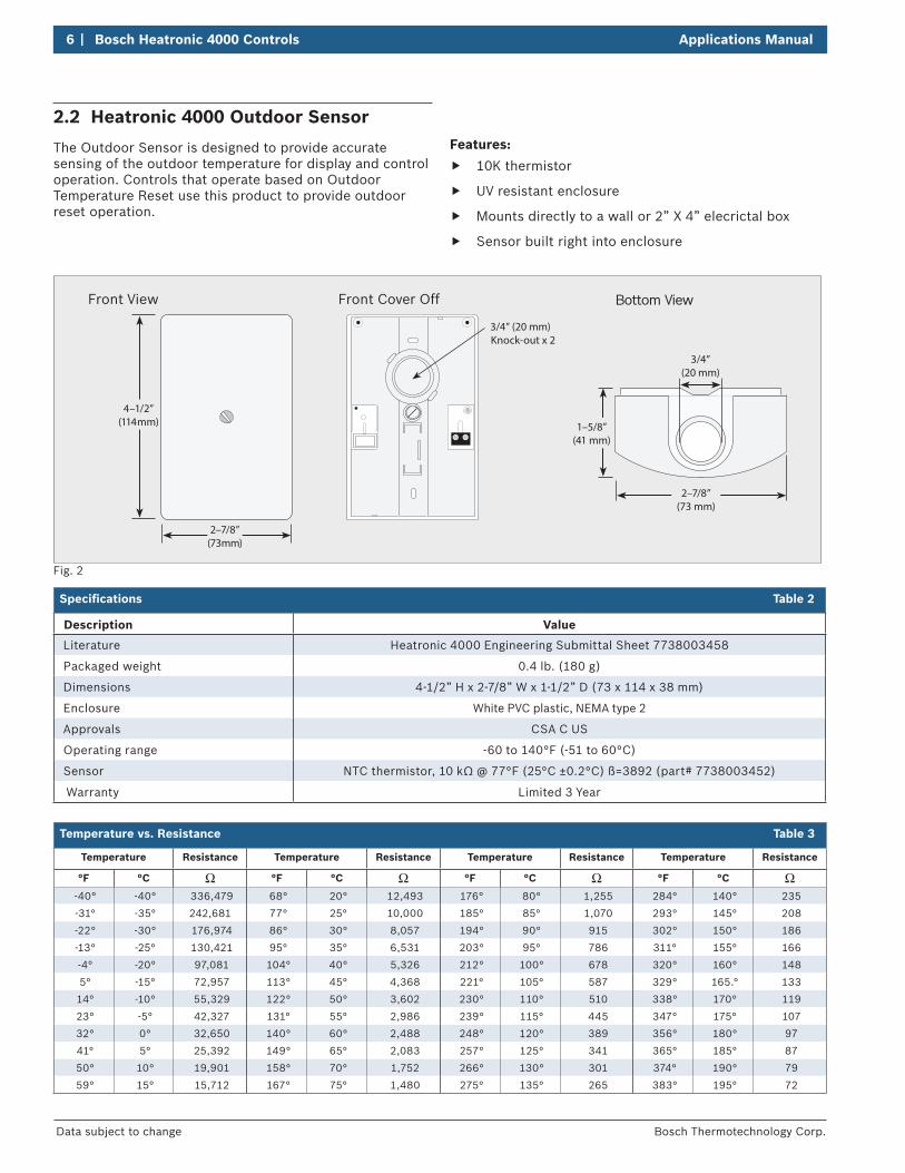
The Outdoor Sensor is designed to provide accurate sensing of the outdoor temperature for display and control operation. Controls that operate based on Outdoor Temperature Reset use this product to provide outdoor reset operation.
F
Front View Front Cover Off Bottom View
2–7/8”(73 mm)
1–5/8”(41 mm)
3/4”(20 mm)
2–7/8”(73 mm)
4–1/2”(114 mm)
3/4” (20 mm) Knock-out x 2
ig. 2
Specifications Table 2
Description Value
Literature Heatronic 4000 Engineering Submittal Sheet 7738003458
Packaged weight 0.4 lb. (180 g)
Dimensions 4-1/2” H x 2-7/8” W x 1-1/2” D (73 x 114 x 38 mm)
Enclosure White PVC plastic, NEMA type 2
Approvals CSA C US
Operating range -60 to 140°F (-51 to 60°C)
Sensor NTC thermistor, 10 kΩ @ 77°F (25°C ±0.2°C) ß=3892 (part# 7738003452)
Warranty Limited 3 Year
Temperature vs. Resistance Table 3
Temperature Resistance Temperature Resistance Temperature Resistance Temperature Resistance
°F °C °F °C °F °C °F °C
-40° -40° 336,479 68° 20° 12,493 176° 80° 1,255 284° 140° 235
-31° -35° 242,681 77° 25° 10,000 185° 85° 1,070 293° 145° 208
-22° -30° 176,974 86° 30° 8,057 194° 90° 915 302° 150° 186
-13° -25° 130,421 95° 35° 6,531 203° 95° 786 311° 155° 166
-4° -20° 97,081 104° 40° 5,326 212° 100° 678 320° 160° 148
5° -15° 72,957 113° 45° 4,368 221° 105° 587 329° 165.° 133
14° -10° 55,329 122° 50° 3,602 230° 110° 510 338° 170° 119
23° -5° 42,327 131° 55° 2,986 239° 115° 445 347° 175° 107
32° 0° 32,650 140° 60° 2,488 248° 120° 389 356° 180° 97
41° 5° 25,392 149° 65° 2,083 257° 125° 341 365° 185° 87
50° 10° 19,901 158° 70° 1,752 266° 130° 301 374° 190° 79
59° 15° 15,712 167° 75° 1,480 275° 135° 265 383° 195° 72
Features:
f 10K thermistor
f UV resistant enclosure
f Mounts directly to a wall or 2” X 4” elecrictal box
f Sensor built right into enclosure
Applications Manual Bosch Heatronic 4000 Controls | 7
Bosch Thermotechnology Corp. Data subject to change
2.3 Heatronic 4000 Universal Sensor
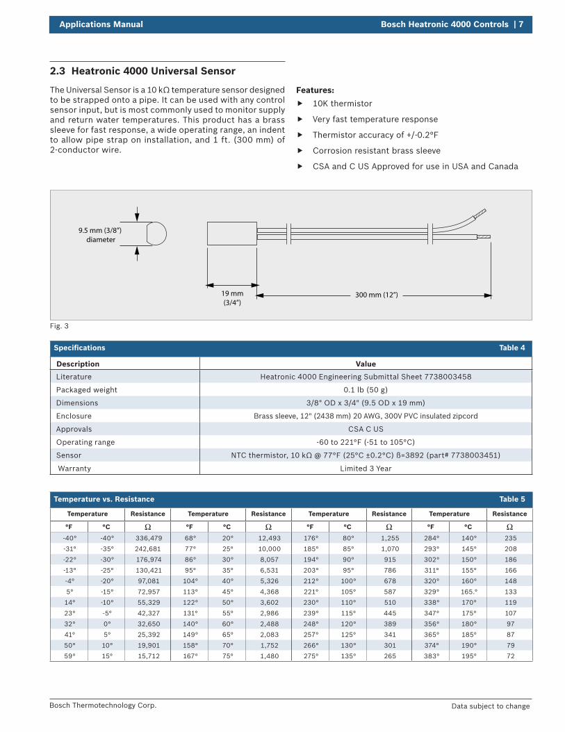
The Universal Sensor is a 10 kΩ temperature sensor designed to be strapped onto a pipe. It can be used with any control sensor input, but is most commonly used to monitor supply and return water temperatures. This product has a brass sleeve for fast response, a wide operating range, an indent to allow pipe strap on installation, and 1 ft. (300 mm) of 2-conductor wire.
300 mm (12”)
9.5 mm (3/8”) diameter
19 mm(3/4”)
Fig. 3
Specifications Table 4
Description Value
Literature Heatronic 4000 Engineering Submittal Sheet 7738003458
Packaged weight 0.1 lb (50 g)
Dimensions 3/8" OD x 3/4" (9.5 OD x 19 mm)
Enclosure Brass sleeve, 12" (2438 mm) 20 AWG, 300V PVC insulated zipcord
Approvals CSA C US
Operating range -60 to 221°F (-51 to 105°C)
Sensor NTC thermistor, 10 kΩ @ 77°F (25°C ±0.2°C) ß=3892 (part# 7738003451)
Warranty Limited 3 Year
Temperature vs. Resistance Table 5
Temperature Resistance Temperature Resistance Temperature Resistance Temperature Resistance
°F °C °F °C °F °C °F °C
-40° -40° 336,479 68° 20° 12,493 176° 80° 1,255 284° 140° 235
-31° -35° 242,681 77° 25° 10,000 185° 85° 1,070 293° 145° 208
-22° -30° 176,974 86° 30° 8,057 194° 90° 915 302° 150° 186
-13° -25° 130,421 95° 35° 6,531 203° 95° 786 311° 155° 166
-4° -20° 97,081 104° 40° 5,326 212° 100° 678 320° 160° 148
5° -15° 72,957 113° 45° 4,368 221° 105° 587 329° 165.° 133
14° -10° 55,329 122° 50° 3,602 230° 110° 510 338° 170° 119
23° -5° 42,327 131° 55° 2,986 239° 115° 445 347° 175° 107
32° 0° 32,650 140° 60° 2,488 248° 120° 389 356° 180° 97
41° 5° 25,392 149° 65° 2,083 257° 125° 341 365° 185° 87
50° 10° 19,901 158° 70° 1,752 266° 130° 301 374° 190° 79
59° 15° 15,712 167° 75° 1,480 275° 135° 265 383° 195° 72
Features:
f 10K thermistor
f Very fast temperature response
f Thermistor accuracy of +/-0.2°F
f Corrosion resistant brass sleeve
f CSA and C US Approved for use in USA and Canada
8 | Bosch Heatronic 4000 Controls Applications Manual
Bosch Thermotechnology Corp.Data subject to change
3 Applications
3.1 Common Boiler Piping/Wiring Configurations
DISCLAIMER: Improper installation, setup, modification, operation or maintenance of the heating system can cause personal injury and property damage. Follow each appliances' instructions precisely. For assistance or further information, contact a trained and certified installer, service provider, or the gas supply company. Application drawings in this manual are conceptual only and do not purport to address all design, installation, code, or safety considerations. The diagrams in this manual are for reference use by code officials, designers and licensed installers. It is expected that installers have adequate knowledge of national and local codes, as well as accepted industry practices, and are trained on equipment, procedures, and applications involved. Drawings are not to scale. Refer to the boiler, control and module installer manuals for additional detailed information!
Application 1Single Temperature System with two 2-Stage non-condensing boilers for space heating load. Installed with Primary/Secondary piping arrangement. (pg 10)
Application 2Single Temperature System with two modulating condensing boilers for space heating and indirect DHW loads. Installed with reverse / return piping arrangement. (pg. 12)
Application 3Single Temperature System with two modulating condensing boilers for space heating and indirect DHW loads. Installed with Primary/Secondary piping arrangement. (pg. 14)
Application 4Single Temperature System with four modulating condensing boilers for space heating loads. The fourth boiler also provides indirect DHW priority. Installed with Primary/Secondary piping arrangement with near DHW piping arrangement. (pg. 16)
Application 5Single Temperature System with one Dual Fuel modulating condensing gas / non condensing oil and one modulating condensing gas boilers for space heating and indirect DHW loads. Installed with reverse / return and injection piping arrangement. (pg. 18)
Application 6Two Temperature System with two 2-Stage non-condensing boilers and two modulating condensing boilers for space heating and indirect DHW loads. Installed with unique high and low temperature return piping arrangement. (pg. 20)
Applications Manual Bosch Heatronic 4000 Controls | 9
Bosch Thermotechnology Corp. Data subject to change
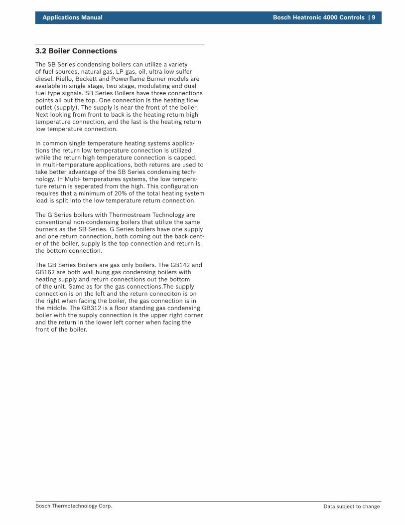
3.2 Boiler Connections
The SB Series condensing boilers can utilize a variety of fuel sources, natural gas, LP gas, oil, ultra low sulfer diesel. Riello, Beckett and Powerflame Burner models are available in single stage, two stage, modulating and dual fuel type signals. SB Series Boilers have three connections points all out the top. One connection is the heating flow outlet (supply). The supply is near the front of the boiler. Next looking from front to back is the heating return high temperature connection, and the last is the heating return low temperature connection.
In common single temperature heating systems applica-tions the return low temperature connection is utilized while the return high temperature connection is capped. In multi-temperature applications, both returns are used to take better advantage of the SB Series condensing tech-nology. In Multi- temperatures systems, the low tempera-ture return is seperated from the high. This configuration requires that a minimum of 20% of the total heating system load is split into the low temperature return connection.
The G Series boilers with Thermostream Technology are conventional non-condensing boilers that utilize the same burners as the SB Series. G Series boilers have one supply and one return connection, both coming out the back cent-er of the boiler, supply is the top connection and return is the bottom connection.
The GB Series Boilers are gas only boilers. The GB142 and GB162 are both wall hung gas condensing boilers with heating supply and return connections out the bottom of the unit. Same as for the gas connections.The supply connection is on the left and the return conneciton is on the right when facing the boiler, the gas connection is in the middle. The GB312 is a floor standing gas condensing boiler with the supply connection is the upper right corner and the return in the lower left corner when facing the front of the boiler.
10 | Bosch Heatronic 4000 Controls Applications Manual
Bosch Thermotechnology Corp.Data subject to change
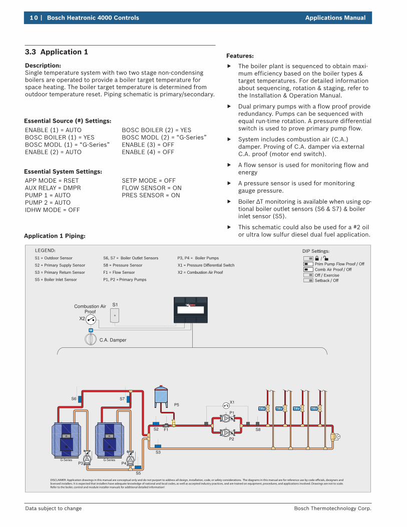
Features:
f The boiler plant is sequenced to obtain maxi-mum efficiency based on the boiler types & target temperatures. For detailed information about sequencing, rotation & staging, refer to the Installation & Operation Manual.
f Dual primary pumps with a flow proof provide redundancy. Pumps can be sequenced with equal run-time rotation. A pressure differential switch is used to prove primary pump flow.
f System includes combustion air (C.A.) damper. Proving of C.A. damper via external C.A. proof (motor end switch).
f A flow sensor is used for monitoring flow and energy
f A pressure sensor is used for monitoring gauge pressure.
f Boiler ∆T monitoring is available when using op-tional boiler outlet sensors (S6 & S7) & boiler inlet sensor (S5).
f This schematic could also be used for a #2 oil or ultra low sulfur diesel dual fuel application.
3.3 Application 1
Description: Single temperature system with two two stage non-condensing boilers are operated to provide a boiler target temperature for space heating. The boiler target temperature is determined from outdoor temperature reset. Piping schematic is primary/secondary.
APP MODE = RSETAUX RELAY = DMPRPUMP 1 = AUTOPUMP 2 = AUTOIDHW MODE = OFF
SETP MODE = OFFFLOW SENSOR = ONPRES SENSOR = ON
Application 1 Piping:
LEGEND:
P3 P4
P5
P1
X1
P2
S2
S6 S7
F1 S8
S3
S5
S1
C.A. Damper
Combustion AirProof
S1 = Outdoor Sensor
S2 = Primary Supply Sensor
F1 = Flow Sensor
S3 = Primary Return Sensor
S5 = Boiler Inlet Sensor
S6, S7 = Boiler Outlet Sensors
S8 = Pressure Sensor
P1, P2 =
Primary Pumps
P3, P4 = Boiler Pumps
X1 = Pressure Differential Switch
X2 = Combustion Air Proof
G-SeriesG-Series
X2
DISCLAIMER: Application drawings in this manual are conceptual only and do not purport to address all design, installation, code, or safety considerations. The diagrams in this manual are for reference use by code ocials, designers and licensed installers. It is expected that installers have adequate knowledge of national and local codes, as well as accepted industry practices, and are trained on equipment, procedures, and applications involved. Drawings are not to scale. Refer to the boiler, control and module installer manuals for additional detailed information!
DIP Settings:
Prim Pump Flow Proof / Off Comb Air Proof / OffOff / Exercise Setback / Off
ENABLE (1) = AUTO BOSC BOILER (1) = YESBOSC MODL (1) = “G-Series”ENABLE (2) = AUTO
BOSC BOILER (2) = YESBOSC MODL (2) = “G-Series”ENABLE (3) = OFFENABLE (4) = OFF
Essential Source (#) Settings:
Essential System Settings:
Applications Manual Bosch Heatronic 4000 Controls | 11
Bosch Thermotechnology Corp. Data subject to change
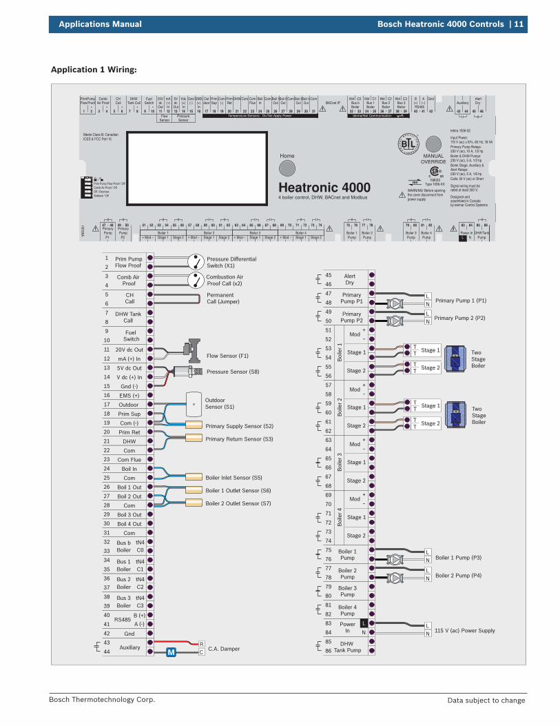
Application 1 Wiring:
LN
Primary Pump 2 (P2)
Combustion AirProof Call (x2)
Pressure Sensor (S8)
Flow Sensor (F1)
Pressure DifferentialSwitch (X1)
C.A. DamperRC
LN
LN
Stage 1TT
Boiler 1 Pump (P3)
Boiler 2 Pump (P4)
115 V (ac) Power Supply
Prim Pump Flow Proof
Comb Air Proof
CHCall
DHW TankCall
Fuel Switch
20V dc Out
5V dc Out
V dc (+) In
Gnd (-)
EMS (+)
Outdoor
Prim Sup
Prim Ret
DHW
Com
Com (-)
mA (+) In
1
2
3
4
PrimaryPump P1
PrimaryPump P2
47
48
49
50
5
6
7
8
Auxiliary43
44
Bus bBoiler
Boiler
Boiler
Boiler
tN4C0
Bus 1 tN4C1
Bus 2 tN4C2
Bus 3 tN4C3
32
33
34
35
36
37
38
39
RS485A (-)
B (+)40
41
9
10
11
12
13
14
15
16
17
18
19
20
21
22
Com Flue
Boil In
Com
Boil 1 Out
Boil 2 Out
Boil 3 Out
Boil 4 Out
Com
23
24
25
26
27
Gnd42
28
29
30
AlertDry
45
46
Boiler 1Pump
Boiler 2Pump
75
76
77
78
Boiler 3Pump
Boiler 4Pump
PowerIn
79
80
81
82
DHW Tank Pump
85
86
53
54Stage 1
Stage 2
Boi
ler 1
51
52
55
56
N
83
84
59
60Stage 1
Stage 2
Boi
ler 2
57
58
61
62
65
66Stage 1
Stage 2
Boi
ler 3
63
64
67
68
71
72Stage 1
Stage 2
Boi
ler 4
69
70
73
74
L
Com31
Primary Pump 1 (P1)
Primary Supply Sensor (S2)
Primary Return Sensor (S3)
Boiler 1 Outlet Sensor (S6)
Boiler 2 Outlet Sensor (S7)
Boiler Inlet Sensor (S5)
OutdoorSensor (S1)
Mod+
-
Mod+
-
Mod+
-
Mod+
-
Stage 1TT
LN
LN
TwoStage Boiler
Two Stage Boiler
Stage 2TT
Stage 2TT
PermanentCall (Jumper)
12
34
5
Temperature Sensors - Do Not Apply Power tekmarNet Communication
C3C2C0 C1
H6106A Boiler 1
75 76
PumpBoiler 2
77 78
PumpBoiler 3
79 80
PumpBoiler 4
81 82
PumpPower InL N
45 46
Auxiliary
43 44
Pump
47 48
P1Pump
Primary Primary49 50
P2
85 8683 84
20V
11
dc5Vdc
Out In Out In In
Vdc
14
(+) (+)Gnd
15
(-) (-)mA
12 13
(+)EMS
16 17
PrimSup
18
Com
19
PrimRet
BoilIn
20
DHW
21
Com
22 23 24 25
Boil 1Out
26
Boil 2Out
27
ComCom
28
Com
31
Boil 3Out
29
Boil 4Out
30
tN4
32 33
Bus btN4
34 35
Bus 1tN4
36 37
Bus 2tN4
38 39
Bus 3Boiler Boiler Boiler Boiler
PrimPump
1 2
Comb
3 4
Air ProofCH
5 6
CallDHW
7 8
Tank CallFuel
9 10
Switch
FlowSensor
PressureSensor
B A
40 41
BACnet IPRS485
42
Gnd
Prim Pump Flow Proof / OffComb Air Proof / OffOff / ExerciseSetback / Off
51 52
ModBoiler 1
53 54
Stage 1 Stage 2
55 56
+ - Mod Stage 1 Stage 2+ - Mod Stage 1 Stage 2+ - Mod Stage 1 Stage 2+ -
57 58
Boiler 2
59 60 61 62 63 64
Boiler 3
65 66 67 68 69 70
Boiler 4
71 72 73 74
WARNING! Before openingthe cover disconnect frompower supply
Meets Class B: CanadianICES & FCC Part 15
4 boiler control, DHW, BACnet and Modbus
MANUALOVERRIDE
Home
Outdoor
ComFlue
AlertDryFlow Proof
TankDHWPump
(+) (–)
Heatronic 4000158033
Type 1056-XX
tektra 1056-02
Designed and assembled in Canadaby tekmar Control Systems
Signal wiring must be rated at least 300 V.
Input Power: 115 V (ac) ±10%, 60 Hz, 18 VAPrimary Pump Relays: 230 V (ac), 10 A, 1/2 hpBoiler & DHW Pumps: 230 V (ac), 5 A, 1/3 hpBoiler Stage, Auxiliary & Alert Relays: 230 V (ac), 5 A, 1/6 hpCalls: 24 V (ac) or Short
12 | Bosch Heatronic 4000 Controls Applications Manual
Bosch Thermotechnology Corp.Data subject to change
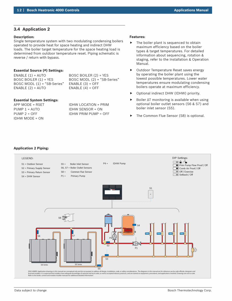
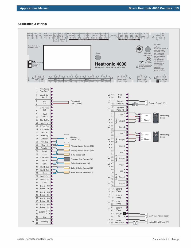
3.4 Application 2
Description: Single temperature system with two modulating condensing boilers operated to provide heat for space heating and indirect DHW loads. The boiler target temperature for the space heating load is determined from outdoor temperature reset. Piping schematic is reverse / return with bypass.
Essential Source (#) Settings:ENABLE (1) = AUTOBOSC BOILER (1) = YESBOSC MODL (1) = “SB-Series”ENABLE (2) = AUTO
BOSC BOILER (2) = YESBOSC MODL (2) = “SB-Series”ENABLE (3) = OFFENABLE (4) = OFF
Essential System Settings:APP MODE = RSETPUMP 1 = AUTOPUMP 2 = OFFIDHW MODE = ON
IDHW LOCATION = PRIMIDHW SENSOR = ONIDHW PRIM PUMP = OFF
Application 2 Piping:
LEGEND:
S8
S2
S3
S6P4
P1
S1
S7
S4
S1 = Outdoor Sensor
S2 = Primary Supply Sensor
S3 = Primary Return Sensor
S4 = DHW Sensor
S6, S7 = Boiler Outlet Sensors
S8 = Common Flue Sensor
P1 = Primary Pump
P4 = IDHW Pump
SB SeriesSB Series
S5
S5 = Boiler Inlet Sensor
DISCLAIMER: Application drawings in this manual are conceptual only and do not purport to address all design, installation, code, or safety considerations. The diagrams in this manual are for reference use by code ocials, designers and licensed installers. It is expected that installers have adequate knowledge of national and local codes, as well as accepted industry practices, and are trained on equipment, procedures, and applications involved. Drawings are not to scale. Refer to the boiler, control and module installer manuals for additional detailed information!
DIP Settings:
Prim Pump Flow Proof / Off Comb Air Proof / OffOff / Exercise Setback / Off
Features:
f The boiler plant is sequenced to obtain maximum efficiency based on the boiler types & target temperatures. For detailed information about sequencing, rotation & staging, refer to the Installation & Operation Manual.
f Outdoor Temperature Reset saves energy by operating the boiler plant using the lowest possible temperatures. Lower water temperatures ensure modulating condensing boilers operate at maximum efficiency.
f Optional indirect DHW (IDHW) priority.
f Boiler ∆T monitoring is available when using optional boiler outlet sensors (S6 & S7) and boiler inlet sensor (S5).
f The Common Flue Sensor (S8) is optional.
Applications Manual Bosch Heatronic 4000 Controls | 13
Bosch Thermotechnology Corp. Data subject to change
Application 2 Wiring:
Indirect DHW Pump (P4)LN
Common Flue Sensor (S8)
LN
Mod
Stage 1TT
+-
ModulatingBoiler
115 V (ac) Power Supply
Prim Pump Flow Proof
Comb Air Proof
CHCall
DHW TankCall
Fuel Switch
20V dc Out
5V dc Out
V dc (+) In
Gnd (-)
EMS (+)
Outdoor
Prim Sup
Prim Ret
DHW
Com
Com (-)
mA (+) In
1
2
3
4
PrimaryPump P1
PrimaryPump P2
47
48
49
50
5
6
7
8
Auxiliary43
44
Bus bBoiler
Boiler
Boiler
Boiler
tN4C0
Bus 1 tN4C1
Bus 2 tN4C2
Bus 3 tN4C3
32
33
34
35
36
37
38
39
9
10
11
12
13
14
15
16
17
18
19
20
21
22
Com Flue
Boil In
Com
Boil 1 Out
Boil 2 Out
Boil 3 Out
Boil 4 Out
Com
23
24
25
26
27
Gnd42
28
29
30
AlertDry
45
46
Boiler 1Pump
Boiler 2Pump
75
76
77
78
Boiler 3Pump
Boiler 4Pump
PowerIn
79
80
81
82
DHW Tank Pump
85
86
53
54Stage 1
Stage 2
Boi
ler 1
51
52
55
56
N
83
84
59
60Stage 1
Stage 2
Boi
ler 2
57
58
61
62
65
66Stage 1
Stage 2
Boi
ler 3
63
64
67
68
71
72Stage 1
Stage 2
Boi
ler 4
69
70
73
74
L
Com31
Primary Pump 1 (P1)
ModulatingBoiler
Primary Supply Sensor (S2)
Primary Return Sensor (S3)
DHW Sensor (S4)
Boiler 1 Outlet Sensor (S6)
Boiler 2 Outlet Sensor (S7)
OutdoorSensor (S1)
Mod+
-
Mod+
-
Mod+
-
Mod+
-
Mod
Stage 1TT
+-
LN
LN Indirect DHW Pump (P4)
Boiler Inlet Sensor (S5)
RS485A (-)
B (+)40
41
PermanentCall (Jumper)
12
34
5
Temperature Sensors - Do Not Apply Power tekmarNet Communication
C3C2C0 C1
H6106A Boiler 1
75 76
PumpBoiler 2
77 78
PumpBoiler 3
79 80
PumpBoiler 4
81 82
PumpPower InL N
45 46
Auxiliary
43 44
Pump
47 48
P1Pump
Primary Primary49 50
P2
85 8683 84
20V
11
dc5Vdc
Out In Out In In
Vdc
14
(+) (+)Gnd
15
(-) (-)mA
12 13
(+)EMS
16 17
PrimSup
18
Com
19
PrimRet
BoilIn
20
DHW
21
Com
22 23 24 25
Boil 1Out
26
Boil 2Out
27
ComCom
28
Com
31
Boil 3Out
29
Boil 4Out
30
tN4
32 33
Bus btN4
34 35
Bus 1tN4
36 37
Bus 2tN4
38 39
Bus 3Boiler Boiler Boiler Boiler
PrimPump
1 2
Comb
3 4
Air ProofCH
5 6
CallDHW
7 8
Tank CallFuel
9 10
Switch
FlowSensor
PressureSensor
B A
40 41
BACnet IPRS485
42
Gnd
Prim Pump Flow Proof / OffComb Air Proof / OffOff / ExerciseSetback / Off
51 52
ModBoiler 1
53 54
Stage 1 Stage 2
55 56
+ - Mod Stage 1 Stage 2+ - Mod Stage 1 Stage 2+ - Mod Stage 1 Stage 2+ -
57 58
Boiler 2
59 60 61 62 63 64
Boiler 3
65 66 67 68 69 70
Boiler 4
71 72 73 74
WARNING! Before openingthe cover disconnect frompower supply
Meets Class B: CanadianICES & FCC Part 15
4 boiler control, DHW, BACnet and Modbus
MANUALOVERRIDE
Home
Outdoor
ComFlue
AlertDryFlow Proof
TankDHWPump
(+) (–)
Heatronic 4000158033
Type 1056-XX
tektra 1056-02
Designed and assembled in Canadaby tekmar Control Systems
Signal wiring must be rated at least 300 V.
Input Power: 115 V (ac) ±10%, 60 Hz, 18 VAPrimary Pump Relays: 230 V (ac), 10 A, 1/2 hpBoiler & DHW Pumps: 230 V (ac), 5 A, 1/3 hpBoiler Stage, Auxiliary & Alert Relays: 230 V (ac), 5 A, 1/6 hpCalls: 24 V (ac) or Short
14 | Bosch Heatronic 4000 Controls Applications Manual
Bosch Thermotechnology Corp.Data subject to change
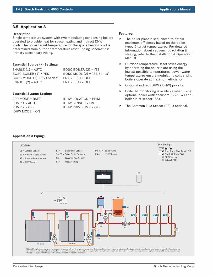
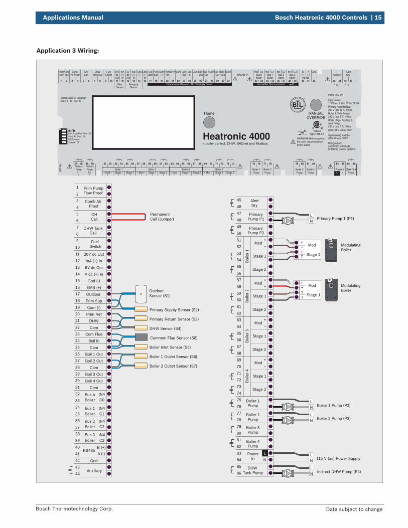
3.5 Application 3
Description: Single temperature system with two modulating condensing boilers operated to provide heat for space heating and indirect DHW loads. The boiler target temperature for the space heating load is determined from outdoor temperature reset. Piping Schematic is Primary /Secondary Piping.
Essential Source (#) Settings:
ENABLE (1) = AUTOBOSC BOILER (1) = YESBOSC MODL (1) = “SB-Series”ENABLE (2) = AUTO
BOSC BOILER (2) = YESBOSC MODL (2) = “SB-Series”ENABLE (3) = OFFENABLE (4) = OFF
Essential System Settings:
APP MODE = RSETPUMP 1 = AUTOPUMP 2 = OFFIDHW MODE = ON
IDHW LOCATION = PRIMIDHW SENSOR = ONIDHW PRIM PUMP = OFF
Application 3 Piping:
LEGEND:
S8
S2
S3
S6P4
P1
S1
S7
S4
S1 = Outdoor Sensor
S2 = Primary Supply Sensor
S3 = Primary Return Sensor
S4 = DHW Sensor
S6, S7 = Boiler Outlet Sensors
S8 = Common Flue Sensor
P1 = Primary Pump
P4 = IDHW Pump
SB SeriesSB Series P3P2
S5 = Boiler Inlet Sensor
S5
P2, P3 = Boiler Pump
DISCLAIMER: Application drawings in this manual are conceptual only and do not purport to address all design, installation, code, or safety considerations. The diagrams in this manual are for reference use by code ocials, designers and licensed installers. It is expected that installers have adequate knowledge of national and local codes, as well as accepted industry practices, and are trained on equipment, procedures, and applications involved. Drawings are not to scale. Refer to the boiler, control and module installer manuals for additional detailed information!
DIP Settings:
Prim Pump Flow Proof / Off Comb Air Proof / OffOff / Exercise Setback / Off
Features:
f The boiler plant is sequenced to obtain maximum efficiency based on the boiler types & target temperatures. For detailed information about sequencing, rotation & staging, refer to the Installation & Operation Manual.
f Outdoor Temperature Reset saves energy by operating the boiler plant using the lowest possible temperatures. Lower water temperatures ensure modulating condensing boilers operate at maximum efficiency.
f Optional indirect DHW (IDHW) priority.
f Boiler ∆T monitoring is available when using optional boiler outlet sensors (S6 & S7) and boiler inlet sensor (S5).
f The Common Flue Sensor (S8) is optional.
Applications Manual Bosch Heatronic 4000 Controls | 15
Bosch Thermotechnology Corp. Data subject to change
Application 3 Wiring:
Indirect DHW Pump (P4)LN
Common Flue Sensor (S8)
LN
LN
Mod
Stage 1TT
+-
ModulatingBoiler
Boiler 1 Pump (P2)
Boiler 2 Pump (P3)
115 V (ac) Power Supply
Prim Pump Flow Proof
Comb Air Proof
CHCall
DHW TankCall
Fuel Switch
20V dc Out
5V dc Out
V dc (+) In
Gnd (-)
EMS (+)
Outdoor
Prim Sup
Prim Ret
DHW
Com
Com (-)
mA (+) In
1
2
3
4
PrimaryPump P1
PrimaryPump P2
47
48
49
50
5
6
7
8
Auxiliary43
44
Bus bBoiler
Boiler
Boiler
Boiler
tN4C0
Bus 1 tN4C1
Bus 2 tN4C2
Bus 3 tN4C3
32
33
34
35
36
37
38
39
9
10
11
12
13
14
15
16
17
18
19
20
21
22
Com Flue
Boil In
Com
Boil 1 Out
Boil 2 Out
Boil 3 Out
Boil 4 Out
Com
23
24
25
26
27
Gnd42
28
29
30
AlertDry
45
46
Boiler 1Pump
Boiler 2Pump
75
76
77
78
Boiler 3Pump
Boiler 4Pump
PowerIn
79
80
81
82
DHW Tank Pump
85
86
53
54Stage 1
Stage 2
Boi
ler 1
51
52
55
56
N
83
84
59
60Stage 1
Stage 2
Boi
ler 2
57
58
61
62
65
66Stage 1
Stage 2
Boi
ler 3
63
64
67
68
71
72Stage 1
Stage 2
Boi
ler 4
69
70
73
74
L
Com31
Primary Pump 1 (P1)
ModulatingBoiler
Primary Supply Sensor (S2)
Primary Return Sensor (S3)
DHW Sensor (S4)
Boiler 1 Outlet Sensor (S6)
Boiler 2 Outlet Sensor (S7)
Boiler Inlet Sensor (S5)
OutdoorSensor (S1)
Mod+
-
Mod+
-
Mod+
-
Mod+
-
Mod
Stage 1TT
+-
LN
LN
RS485A (-)
B (+)40
41
PermanentCall (Jumper)
12
34
5
Temperature Sensors - Do Not Apply Power tekmarNet Communication
C3C2C0 C1
H6106A Boiler 1
75 76
PumpBoiler 2
77 78
PumpBoiler 3
79 80
PumpBoiler 4
81 82
PumpPower InL N
45 46
Auxiliary
43 44
Pump
47 48
P1Pump
Primary Primary49 50
P2
85 8683 84
20V
11
dc5Vdc
Out In Out In In
Vdc
14
(+) (+)Gnd
15
(-) (-)mA
12 13
(+)EMS
16 17
PrimSup
18
Com
19
PrimRet
BoilIn
20
DHW
21
Com
22 23 24 25
Boil 1Out
26
Boil 2Out
27
ComCom
28
Com
31
Boil 3Out
29
Boil 4Out
30
tN4
32 33
Bus btN4
34 35
Bus 1tN4
36 37
Bus 2tN4
38 39
Bus 3Boiler Boiler Boiler Boiler
PrimPump
1 2
Comb
3 4
Air ProofCH
5 6
CallDHW
7 8
Tank CallFuel
9 10
Switch
FlowSensor
PressureSensor
B A
40 41
BACnet IPRS485
42
Gnd
Prim Pump Flow Proof / OffComb Air Proof / OffOff / ExerciseSetback / Off
51 52
ModBoiler 1
53 54
Stage 1 Stage 2
55 56
+ - Mod Stage 1 Stage 2+ - Mod Stage 1 Stage 2+ - Mod Stage 1 Stage 2+ -
57 58
Boiler 2
59 60 61 62 63 64
Boiler 3
65 66 67 68 69 70
Boiler 4
71 72 73 74
WARNING! Before openingthe cover disconnect frompower supply
Meets Class B: CanadianICES & FCC Part 15
4 boiler control, DHW, BACnet and Modbus
MANUALOVERRIDE
Home
Outdoor
ComFlue
AlertDryFlow Proof
TankDHWPump
(+) (–)
Heatronic 4000158033
Type 1056-XX
tektra 1056-02
Designed and assembled in Canadaby tekmar Control Systems
Signal wiring must be rated at least 300 V.
Input Power: 115 V (ac) ±10%, 60 Hz, 18 VAPrimary Pump Relays: 230 V (ac), 10 A, 1/2 hpBoiler & DHW Pumps: 230 V (ac), 5 A, 1/3 hpBoiler Stage, Auxiliary & Alert Relays: 230 V (ac), 5 A, 1/6 hpCalls: 24 V (ac) or Short
16 | Bosch Heatronic 4000 Controls Applications Manual
Bosch Thermotechnology Corp.Data subject to change
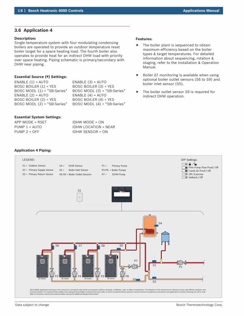
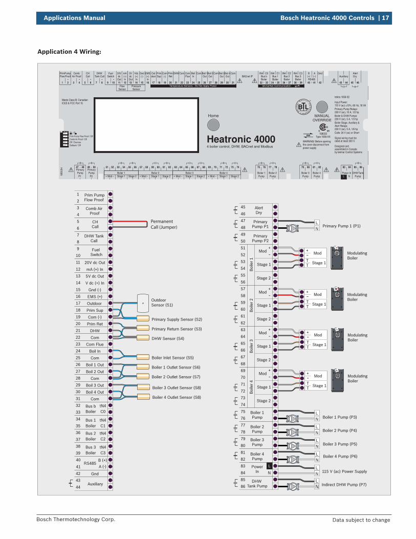
Features:
f The boiler plant is sequenced to obtain maximum efficiency based on the boiler types & target temperatures. For detailed information about sequencing, rotation & staging, refer to the Installation & Operation Manual.
f Boiler ∆T monitoring is available when using optional boiler outlet sensors (S6 to S9) and boiler inlet sensor (S5).
f The boiler outlet sensor S9 is required for indirect DHW operation.
3.6 Application 4
Description: Single temperature system with four modulating condensing boilers are operated to provide an outdoor temperature reset boiler target for a space heating load. The fourth boiler also operates to provide heat for an indirect DHW load with priority over space heating. Piping schematic is primary/secondary with DHW near piping.
Essential Source (#) Settings:ENABLE (1) = AUTOBOSC BOILER (1) = YESBOSC MODL (1) = “SB-Series”ENABLE (2) = AUTOBOSC BOILER (2) = YESBOSC MODL (2) = “SB-Series”
ENABLE (3) = AUTOBOSC BOILER (3) = YESBOSC MODL (3) = “SB-Series”ENABLE (4) = AUTOBOSC BOILER (4) = YESBOSC MODL (4) = “SB-Series”
Essential System Settings:APP MODE = RSETPUMP 1 = AUTOPUMP 2 = OFF
IDHW MODE = ONIDHW LOCATION = NEARIDHW SENSOR = ON
Application 4 Piping:
LEGEND:
P1S2
S3S5
S8S7
P3 P4 P5 P6
S9
S1
S6
P7
S1 = Outdoor Sensor
S2 = Primary Supply Sensor
S3 = Primary Return Sensor
S4 = DHW Sensor
S5 = Boiler Inlet Sensor
S6-S9 = Boiler Outlet Sensors
P1 = Primary Pump
P3-P6 = Boiler Pumps
P7 = IDHW Pump
SB Series SB SeriesSB SeriesSB Series
S4
DISCLAIMER: Application drawings in this manual are conceptual only and do not purport to address all design, installation, code, or safety considerations. The diagrams in this manual are for reference use by code ocials, designers and licensed installers. It is expected that installers have adequate knowledge of national and local codes, as well as accepted industry practices, and are trained on equipment, procedures, and applications involved. Drawings are not to scale. Refer to the boiler, control and module installer manuals for additional detailed information!
DIP Settings:
Prim Pump Flow Proof / Off Comb Air Proof / OffOff / Exercise Setback / Off
Applications Manual Bosch Heatronic 4000 Controls | 17
Bosch Thermotechnology Corp. Data subject to change
Application 4 Wiring:
LN Indirect DHW Pump (P7)
LN
LN Boiler 3 Pump (P5)
ModulatingBoiler
Mod
Stage 1TT
+-
ModulatingBoiler
Mod
Stage 1TT
+-
LN
LN
Mod
Stage 1TT
+-
ModulatingBoiler
Boiler 1 Pump (P3)
Boiler 2 Pump (P4)
115 V (ac) Power Supply
Prim Pump Flow Proof
Comb Air Proof
CHCall
DHW TankCall
Fuel Switch
20V dc Out
5V dc Out
V dc (+) In
Gnd (-)
EMS (+)
Outdoor
Prim Sup
Prim Ret
DHW
Com
Com (-)
mA (+) In
1
2
3
4
PrimaryPump P1
PrimaryPump P2
47
48
49
50
5
6
7
8
Auxiliary43
44
Bus bBoiler
Boiler
Boiler
Boiler
tN4C0
Bus 1 tN4C1
Bus 2 tN4C2
Bus 3 tN4C3
32
33
34
35
36
37
38
39
9
10
11
12
13
14
15
16
17
18
19
20
21
22
Com Flue
Boil In
Com
Boil 1 Out
Boil 2 Out
Boil 3 Out
Boil 4 Out
Com
23
24
25
26
27
Gnd42
28
29
30
AlertDry
45
46
Boiler 1Pump
Boiler 2Pump
75
76
77
78
Boiler 3Pump
Boiler 4Pump
PowerIn
79
80
81
82
DHW Tank Pump
85
86
53
54Stage 1
Stage 2
Boi
ler 1
51
52
55
56
N
83
84
59
60Stage 1
Stage 2
Boi
ler 2
57
58
61
62
65
66Stage 1
Stage 2
Boi
ler 3
63
64
67
68
71
72Stage 1
Stage 2
Boi
ler 4
69
70
73
74
L
Com31
Primary Pump 1 (P1)
ModulatingBoiler
Primary Supply Sensor (S2)
Primary Return Sensor (S3)
DHW Sensor (S4)
Boiler 1 Outlet Sensor (S6)
Boiler 2 Outlet Sensor (S7)
Boiler Inlet Sensor (S5)
OutdoorSensor (S1)
Mod+
-
Mod+
-
Mod+
-
Mod+
-
Mod
Stage 1TT
+-
LN
LN
Boiler 3 Outlet Sensor (S8)
Boiler 4 Outlet Sensor (S8)
Boiler 4 Pump (P6)
PermanentCall (Jumper)
RS485A (-)
B (+)40
41
12
34
5
Temperature Sensors - Do Not Apply Power tekmarNet Communication
C3C2C0 C1
H6106A Boiler 1
75 76
PumpBoiler 2
77 78
PumpBoiler 3
79 80
PumpBoiler 4
81 82
PumpPower InL N
45 46
Auxiliary
43 44
Pump
47 48
P1Pump
Primary Primary49 50
P2
85 8683 84
20V
11
dc5Vdc
Out In Out In In
Vdc
14
(+) (+)Gnd
15
(-) (-)mA
12 13
(+)EMS
16 17
PrimSup
18
Com
19
PrimRet
BoilIn
20
DHW
21
Com
22 23 24 25
Boil 1Out
26
Boil 2Out
27
ComCom
28
Com
31
Boil 3Out
29
Boil 4Out
30
tN4
32 33
Bus btN4
34 35
Bus 1tN4
36 37
Bus 2tN4
38 39
Bus 3Boiler Boiler Boiler Boiler
PrimPump
1 2
Comb
3 4
Air ProofCH
5 6
CallDHW
7 8
Tank CallFuel
9 10
Switch
FlowSensor
PressureSensor
B A
40 41
BACnet IPRS485
42
Gnd
Prim Pump Flow Proof / OffComb Air Proof / OffOff / ExerciseSetback / Off
51 52
ModBoiler 1
53 54
Stage 1 Stage 2
55 56
+ - Mod Stage 1 Stage 2+ - Mod Stage 1 Stage 2+ - Mod Stage 1 Stage 2+ -
57 58
Boiler 2
59 60 61 62 63 64
Boiler 3
65 66 67 68 69 70
Boiler 4
71 72 73 74
WARNING! Before openingthe cover disconnect frompower supply
Meets Class B: CanadianICES & FCC Part 15
4 boiler control, DHW, BACnet and Modbus
MANUALOVERRIDE
Home
Outdoor
ComFlue
AlertDryFlow Proof
TankDHWPump
(+) (–)
Heatronic 4000158033
Type 1056-XX
tektra 1056-02
Designed and assembled in Canadaby tekmar Control Systems
Signal wiring must be rated at least 300 V.
Input Power: 115 V (ac) ±10%, 60 Hz, 18 VAPrimary Pump Relays: 230 V (ac), 10 A, 1/2 hpBoiler & DHW Pumps: 230 V (ac), 5 A, 1/3 hpBoiler Stage, Auxiliary & Alert Relays: 230 V (ac), 5 A, 1/6 hpCalls: 24 V (ac) or Short
18 | Bosch Heatronic 4000 Controls Applications Manual
Bosch Thermotechnology Corp.Data subject to change
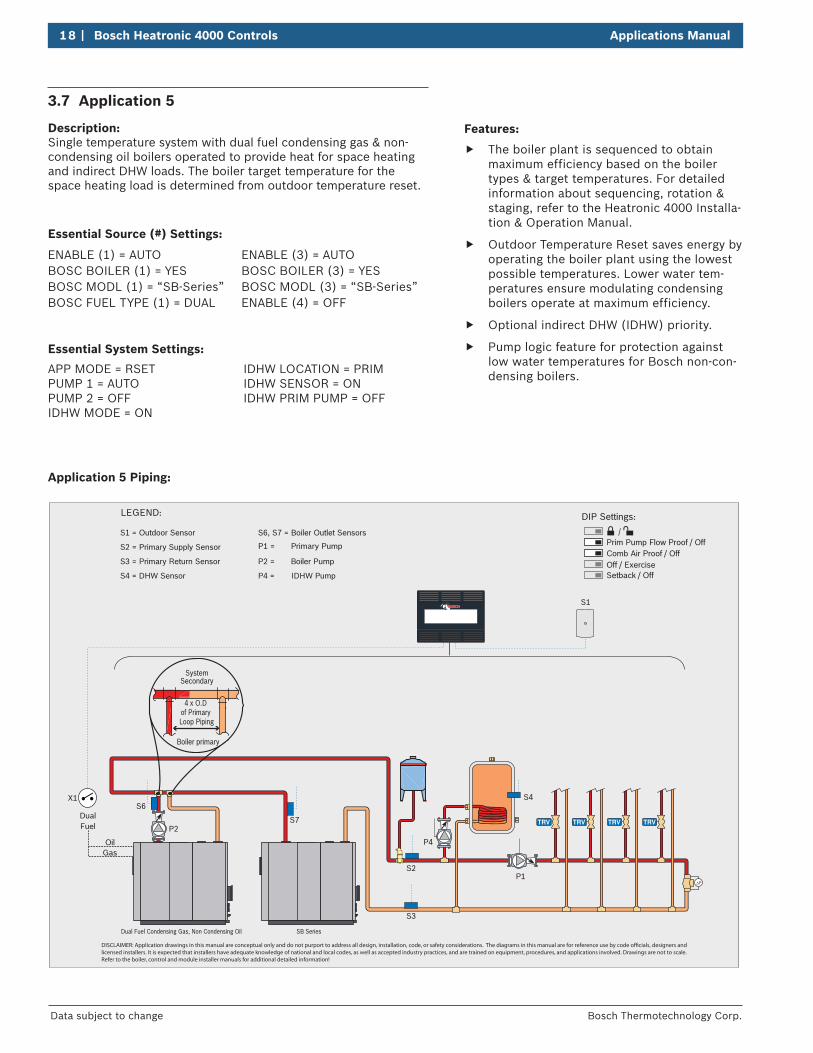
Features:
f The boiler plant is sequenced to obtain maximum efficiency based on the boiler types & target temperatures. For detailed information about sequencing, rotation & staging, refer to the Heatronic 4000 Installa-tion & Operation Manual.
f Outdoor Temperature Reset saves energy by operating the boiler plant using the lowest possible temperatures. Lower water tem-peratures ensure modulating condensing boilers operate at maximum efficiency.
f Optional indirect DHW (IDHW) priority.
f Pump logic feature for protection against low water temperatures for Bosch non-con-densing boilers.
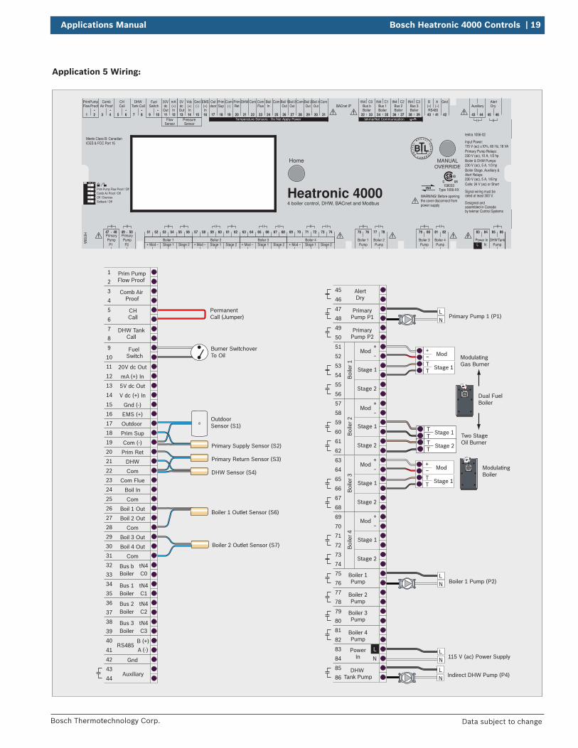
3.7 Application 5
Description: Single temperature system with dual fuel condensing gas & non-condensing oil boilers operated to provide heat for space heating and indirect DHW loads. The boiler target temperature for the space heating load is determined from outdoor temperature reset.
LEGEND:
X1
S2
S3
S6
P4
P1
S1
S7
S4
S1 = Outdoor Sensor
S2 = Primary Supply Sensor
S3 = Primary Return Sensor
S4 = DHW Sensor
S6, S7 = Boiler Outlet Sensors
P1 = Primary Pump
P4 = IDHW Pump
DIP Settings:
Prim Pump Flow Proof / Off Comb Air Proof / OffOff / Exercise Setback / Off
DualFuel
OilGas
SB SeriesDual Fuel Condensing Gas, Non Condensing Oil
P2
P2 = Boiler Pump
Boiler primary
SystemSecondary
4 x O.D of Primary Loop Piping
DISCLAIMER: Application drawings in this manual are conceptual only and do not purport to address all design, installation, code, or safety considerations. The diagrams in this manual are for reference use by code ocials, designers and licensed installers. It is expected that installers have adequate knowledge of national and local codes, as well as accepted industry practices, and are trained on equipment, procedures, and applications involved. Drawings are not to scale. Refer to the boiler, control and module installer manuals for additional detailed information!
Essential Source (#) Settings:
ENABLE (1) = AUTOBOSC BOILER (1) = YESBOSC MODL (1) = “SB-Series”BOSC FUEL TYPE (1) = DUAL
ENABLE (3) = AUTOBOSC BOILER (3) = YESBOSC MODL (3) = “SB-Series”ENABLE (4) = OFF
Essential System Settings:
APP MODE = RSETPUMP 1 = AUTOPUMP 2 = OFFIDHW MODE = ON
IDHW LOCATION = PRIMIDHW SENSOR = ONIDHW PRIM PUMP = OFF
Application 5 Piping:
Applications Manual Bosch Heatronic 4000 Controls | 19
Bosch Thermotechnology Corp. Data subject to change
Application 5 Wiring:
LN
TTTT
Indirect DHW Pump (P4)
Dual FuelBoiler
ModulatingBoiler
Mod
Stage 1TT
+-
Burner SwitchoverTo Oil
PermanentCall (Jumper)
LN
Mod
Stage 1TT
+-
Two Stage Oil Burner
Boiler 1 Pump (P2)
115 V (ac) Power Supply
Prim Pump Flow Proof
Comb Air Proof
CHCall
DHW TankCall
Fuel Switch
20V dc Out
5V dc Out
V dc (+) In
Gnd (-)
EMS (+)
Outdoor
Prim Sup
Prim Ret
DHW
Com
Com (-)
mA (+) In
1
2
3
4
PrimaryPump P1
PrimaryPump P2
47
48
49
50
5
6
7
8
Auxiliary43
44
Bus bBoiler
Boiler
Boiler
Boiler
tN4C0
Bus 1 tN4C1
Bus 2 tN4C2
Bus 3 tN4C3
32
33
34
35
36
37
38
39
9
10
11
12
13
14
15
16
17
18
19
20
21
22
Com Flue
Boil In
Com
Boil 1 Out
Boil 2 Out
Boil 3 Out
Boil 4 Out
Com
23
24
25
26
27
Gnd42
28
29
30
AlertDry
45
46
Boiler 1Pump
Boiler 2Pump
75
76
77
78
Boiler 3Pump
Boiler 4Pump
PowerIn
79
80
81
82
DHW Tank Pump
85
86
53
54Stage 1
Stage 2
Boi
ler 1
51
52
55
56
N
83
84
59
60Stage 1
Stage 2
Boi
ler 2
57
58
61
62
65
66Stage 1
Stage 2
Boi
ler 3
63
64
67
68
71
72Stage 1
Stage 2
Boi
ler 4
69
70
73
74
L
Com31
Primary Pump 1 (P1)
ModulatingGas Burner
Primary Supply Sensor (S2)
Primary Return Sensor (S3)
DHW Sensor (S4)
Boiler 1 Outlet Sensor (S6)
Boiler 2 Outlet Sensor (S7)
OutdoorSensor (S1)
Mod+
-
Mod+
-
Mod+
-
Mod+
-
LN
LN
Stage 1
Stage 2
RS485A (-)
B (+)40
41
12
34
5
Temperature Sensors - Do Not Apply Power tekmarNet Communication
C3C2C0 C1
H6106A Boiler 1
75 76
PumpBoiler 2
77 78
PumpBoiler 3
79 80
PumpBoiler 4
81 82
PumpPower InL N
45 46
Auxiliary
43 44
Pump
47 48
P1Pump
Primary Primary49 50
P2
85 8683 84
20V
11
dc5Vdc
Out In Out In In
Vdc
14
(+) (+)Gnd
15
(-) (-)mA
12 13
(+)EMS
16 17
PrimSup
18
Com
19
PrimRet
BoilIn
20
DHW
21
Com
22 23 24 25
Boil 1Out
26
Boil 2Out
27
ComCom
28
Com
31
Boil 3Out
29
Boil 4Out
30
tN4
32 33
Bus btN4
34 35
Bus 1tN4
36 37
Bus 2tN4
38 39
Bus 3Boiler Boiler Boiler Boiler
PrimPump
1 2
Comb
3 4
Air ProofCH
5 6
CallDHW
7 8
Tank CallFuel
9 10
Switch
FlowSensor
PressureSensor
B A
40 41
BACnet IPRS485
42
Gnd
Prim Pump Flow Proof / OffComb Air Proof / OffOff / ExerciseSetback / Off
51 52
ModBoiler 1
53 54
Stage 1 Stage 2
55 56
+ - Mod Stage 1 Stage 2+ - Mod Stage 1 Stage 2+ - Mod Stage 1 Stage 2+ -
57 58
Boiler 2
59 60 61 62 63 64
Boiler 3
65 66 67 68 69 70
Boiler 4
71 72 73 74
WARNING! Before openingthe cover disconnect frompower supply
Meets Class B: CanadianICES & FCC Part 15
4 boiler control, DHW, BACnet and Modbus
MANUALOVERRIDE
Home
Outdoor
ComFlue
AlertDryFlow Proof
TankDHWPump
(+) (–)
Heatronic 4000158033
Type 1056-XX
tektra 1056-02
Designed and assembled in Canadaby tekmar Control Systems
Signal wiring must be rated at least 300 V.
Input Power: 115 V (ac) ±10%, 60 Hz, 18 VAPrimary Pump Relays: 230 V (ac), 10 A, 1/2 hpBoiler & DHW Pumps: 230 V (ac), 5 A, 1/3 hpBoiler Stage, Auxiliary & Alert Relays: 230 V (ac), 5 A, 1/6 hpCalls: 24 V (ac) or Short
20 | Bosch Heatronic 4000 Controls Applications Manual
Bosch Thermotechnology Corp.Data subject to change
Modbus® / BACnet® IP
S1
C.A. Damper
BAS
Combustion Air Proof
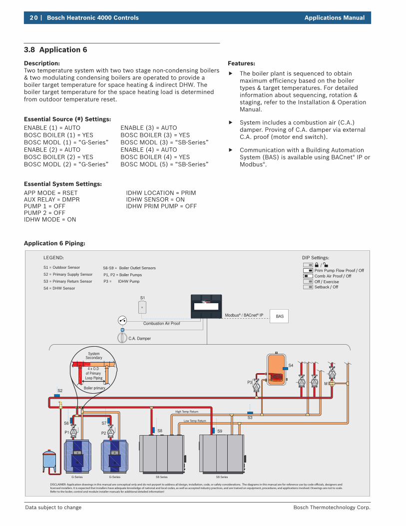
S1 = Outdoor Sensor
S2 = Primary Supply Sensor
S3 = Primary Return Sensor
S4 = DHW Sensor
S6-S9
= Boiler Outlet Sensors
P1, P2 = Boiler Pumps
P3 = IDHW Pump
LEGEND:
S3
MP3
S2
S9
S7
P1 S8
S4
S6
SB SeriesG-Series
High Temp Return
SB SeriesG-Series
P2
Low Temp Return
Boiler primary
SystemSecondary
4 x O.D of Primary Loop Piping
DISCLAIMER: Application drawings in this manual are conceptual only and do not purport to address all design, installation, code, or safety considerations. The diagrams in this manual are for reference use by code ocials, designers and licensed installers. It is expected that installers have adequate knowledge of national and local codes, as well as accepted industry practices, and are trained on equipment, procedures, and applications involved. Drawings are not to scale. Refer to the boiler, control and module installer manuals for additional detailed information!
DIP Settings:
Prim Pump Flow Proof / Off Comb Air Proof / OffOff / Exercise Setback / Off
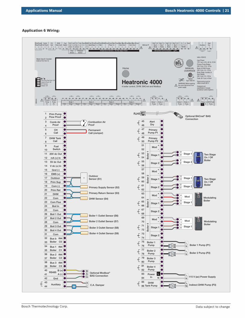
3.8 Application 6
Description: Two temperature system with two two stage non-condensing boilers & two modulating condensing boilers are operated to provide a boiler target temperature for space heating & indirect DHW. The boiler target temperature for the space heating load is determined from outdoor temperature reset.
Essential Source (#) Settings:ENABLE (1) = AUTOBOSC BOILER (1) = YESBOSC MODL (1) = “G-Series”ENABLE (2) = AUTOBOSC BOILER (2) = YESBOSC MODL (2) = “G-Series”
ENABLE (3) = AUTOBOSC BOILER (3) = YESBOSC MODL (3) = “SB-Series”ENABLE (4) = AUTOBOSC BOILER (4) = YESBOSC MODL (5) = “SB-Series”
Essential System Settings:APP MODE = RSETAUX RELAY = DMPRPUMP 1 = OFFPUMP 2 = OFFIDHW MODE = ON
IDHW LOCATION = PRIMIDHW SENSOR = ONIDHW PRIM PUMP = OFF
Application 6 Piping:
Features:
f The boiler plant is sequenced to obtain maximum efficiency based on the boiler types & target temperatures. For detailed information about sequencing, rotation & staging, refer to the Installation & Operation Manual.
f System includes a combustion air (C.A.) damper. Proving of C.A. damper via external C.A. proof (motor end switch).
f Communication with a Building Automation System (BAS) is available using BACnet® IP or Modbus®.
Applications Manual Bosch Heatronic 4000 Controls | 21
Bosch Thermotechnology Corp. Data subject to change
Application 6 Wiring:
LN Indirect DHW Pump (P3)
ModulatingBoiler
Mod
Stage 1TT
+-
ModulatingBoiler
Mod
Stage 1TT
+-
B
GA Optional Modbus®
BAS Connection
Combustion Air Proof
PermanentCall (Jumper)
C.A. DamperRC
LN
Boiler 1 Pump (P1)
Boiler 2 Pump (P2)
115 V (ac) Power Supply
Prim Pump Flow Proof
Comb Air Proof
CHCall
DHW TankCall
Fuel Switch
20V dc Out
5V dc Out
V dc (+) In
Gnd (-)
EMS (+)
Outdoor
Prim Sup
Prim Ret
DHW
Com
Com (-)
mA (+) In
1
2
3
4
PrimaryPump P1
PrimaryPump P2
47
48
49
50
5
6
7
8
Auxiliary43
44
Bus bBoiler
Boiler
Boiler
Boiler
tN4C0
Bus 1 tN4C1
Bus 2 tN4C2
Bus 3 tN4C3
32
33
34
35
36
37
38
39
9
10
11
12
13
14
15
16
17
18
19
20
21
22
Com Flue
Boil In
Com
Boil 1 Out
Boil 2 Out
Boil 3 Out
Boil 4 Out
Com
23
24
25
26
27
Gnd42
28
29
30
AlertDry
45
46
Boiler 1Pump
Boiler 2Pump
75
76
77
78
Boiler 3Pump
Boiler 4Pump
PowerIn
79
80
81
82
DHW Tank Pump
85
86
53
54Stage 1
Stage 2
Bo
iler
151
52
55
56
N
83
84
59
60Stage 1
Stage 2
Bo
iler
2
57
58
61
62
65
66Stage 1
Stage 2
Bo
iler
3
63
64
67
68
71
72Stage 1
Stage 2
Bo
iler
4
69
70
73
74
L
Com31
Two StageOn / OffBoiler
Primary Supply Sensor (S2)
Primary Return Sensor (S3)
DHW Sensor (S4)
Boiler 1 Outlet Sensor (S6)
Boiler 2 Outlet Sensor (S7)
OutdoorSensor (S1)
Mod+
-
Mod+
-
Mod+
-
Mod+
-
LN
LN
Boiler 3 Outlet Sensor (S8)
Boiler 4 Outlet Sensor (S9)
Optional BACnet® BASConnection
RJ45
Stage 1TT
Stage 1TT Two Stage
On / OffBoiler
Stage 2TT
Stage 2TT
RS485A (-)
B (+)40
41
12
34
5
Temperature Sensors - Do Not Apply Power tekmarNet Communication
C3C2C0 C1
H6106A Boiler 1
75 76
PumpBoiler 2
77 78
PumpBoiler 3
79 80
PumpBoiler 4
81 82
PumpPower InL N
45 46
Auxiliary
43 44
Pump
47 48
P1Pump
Primary Primary49 50
P2
85 8683 84
20V
11
dc5Vdc
Out In Out In In
Vdc
14
(+) (+)Gnd
15
(-) (-)mA
12 13
(+)EMS
16 17
PrimSup
18
Com
19
PrimRet
BoilIn
20
DHW
21
Com
22 23 24 25
Boil 1Out
26
Boil 2Out
27
ComCom
28
Com
31
Boil 3Out
29
Boil 4Out
30
tN4
32 33
Bus btN4
34 35
Bus 1tN4
36 37
Bus 2tN4
38 39
Bus 3Boiler Boiler Boiler Boiler
PrimPump
1 2
Comb
3 4
Air ProofCH
5 6
CallDHW
7 8
Tank CallFuel
9 10
Switch
FlowSensor
PressureSensor
B A
40 41
BACnet IPRS485
42
Gnd
Prim Pump Flow Proof / OffComb Air Proof / OffOff / ExerciseSetback / Off
51 52
ModBoiler 1
53 54
Stage 1 Stage 2
55 56
+ - Mod Stage 1 Stage 2+ - Mod Stage 1 Stage 2+ - Mod Stage 1 Stage 2+ -
57 58
Boiler 2
59 60 61 62 63 64
Boiler 3
65 66 67 68 69 70
Boiler 4
71 72 73 74
WARNING! Before openingthe cover disconnect frompower supply
Meets Class B: CanadianICES & FCC Part 15
4 boiler control, DHW, BACnet and Modbus
MANUALOVERRIDE
Home
Outdoor
ComFlue
AlertDryFlow Proof
TankDHWPump
(+) (–)
Heatronic 4000158033
Type 1056-XX
tektra 1056-02
Designed and assembled in Canadaby tekmar Control Systems
Signal wiring must be rated at least 300 V.
Input Power: 115 V (ac) ±10%, 60 Hz, 18 VAPrimary Pump Relays: 230 V (ac), 10 A, 1/2 hpBoiler & DHW Pumps: 230 V (ac), 5 A, 1/3 hpBoiler Stage, Auxiliary & Alert Relays: 230 V (ac), 5 A, 1/6 hpCalls: 24 V (ac) or Short
22 | Bosch Heatronic 4000 Controls Applications Manual
Bosch Thermotechnology Corp.Data subject to change
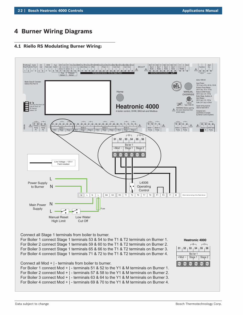
4 Burner Wiring Diagrams
4.1 Riello RS Modulating Burner Wiring:
12
34
5
Temperature Sensors - Do Not Apply Power tekmarNet Communication
C3C2C0 C1
H6106A Boiler 1
75 76
PumpBoiler 2
77 78
PumpBoiler 3
79 80
PumpBoiler 4
81 82
PumpPower InL N
45 46
Auxiliary
43 44
Pump
47 48
P1Pump
Primary Primary49 50
P2
85 8683 84
20V
11
dc5Vdc
Out In Out In In
Vdc
14
(+) (+)Gnd
15
(-) (-)mA
12 13
(+)EMS
16 17
PrimSup
18
Com
19
PrimRet
BoilIn
20
DHW
21
Com
22 23 24 25
Boil 1Out
26
Boil 2Out
27
ComCom
28
Com
31
Boil 3Out
29
Boil 4Out
30
tN4
32 33
Bus btN4
34 35
Bus 1tN4
36 37
Bus 2tN4
38 39
Bus 3Boiler Boiler Boiler Boiler
PrimPump
1 2
Comb
3 4
Air ProofCH
5 6
CallDHW
7 8
Tank CallFuel
9 10
Switch
FlowSensor
PressureSensor
B A
40 41
BACnet IPRS485
42
Gnd
Prim Pump Flow Proof / OffComb Air Proof / OffOff / ExerciseSetback / Off
51 52
ModBoiler 1
53 54
Stage 1 Stage 2
55 56
+ - Mod Stage 1 Stage 2+ - Mod Stage 1 Stage 2+ - Mod Stage 1 Stage 2+ -
57 58
Boiler 2
59 60 61 62 63 64
Boiler 3
65 66 67 68 69 70
Boiler 4
71 72 73 74
WARNING! Before openingthe cover disconnect frompower supply
Meets Class B: CanadianICES & FCC Part 15
4 boiler control, DHW, BACnet and Modbus
MANUALOVERRIDE
Home
Outdoor
ComFlue
AlertDryFlow Proof
TankDHWPump
(+) (–)
Heatronic 4000158033
Type 1056-XX
tektra 1056-02
Designed and assembled in Canadaby tekmar Control Systems
Signal wiring must be rated at least 300 V.
Input Power: 115 V (ac) ±10%, 60 Hz, 18 VAPrimary Pump Relays: 230 V (ac), 10 A, 1/2 hpBoiler & DHW Pumps: 230 V (ac), 5 A, 1/3 hpBoiler Stage, Auxiliary & Alert Relays: 230 V (ac), 5 A, 1/6 hpCalls: 24 V (ac) or Short
Line Voltage – 120 VField installed
L
Power Supply to Burner
N
Other internal wiring of the Riello BurnerB4 S3 R3 T6 T7T1 T2 T8 P1 P2 L N LN
Fuse
Main Power Supply
Y1 M
51 52
ModBoi ler 1
53 54
Stage 1 Stage 2
55 56
+ -
Heatronic 4000
L
NL4006
Operating Control
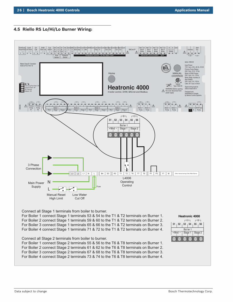
Connect all Stage 1 terminals from boiler to burner.For Boiler 1 connect Stage 1 terminals 53 & 54 to the T1 & T2 terminals on Burner 1.For Boiler 2 connect Stage 1 terminals 59 & 60 to the T1 & T2 terminals on Burner 2.For Boiler 3 connect Stage 1 terminals 65 & 66 to the T1 & T2 terminals on Burner 3.For Boiler 4 connect Stage 1 terminals 71 & 72 to the T1 & T2 terminals on Burner 4.
Connect all Mod + | - terminals from boiler to burner.For Boiler 1 connect Mod + | - terminals 51 & 52 to the Y1 & M terminals on Burner 1.For Boiler 2 connect Mod + | - terminals 57 & 58 to the Y1 & M terminals on Burner 2.For Boiler 3 connect Mod + | - terminals 63 & 64 to the Y1 & M terminals on Burner 3.For Boiler 4 connect Mod + | - terminals 69 & 70 to the Y1 & M terminals on Burner 4.
51 52
ModBoi ler 1
53 54
Stage 1 Stage 2
55 56
+ -
Manual Reset High Limit
Low Water Cut Off
Applications Manual Bosch Heatronic 4000 Controls | 23
Bosch Thermotechnology Corp. Data subject to change
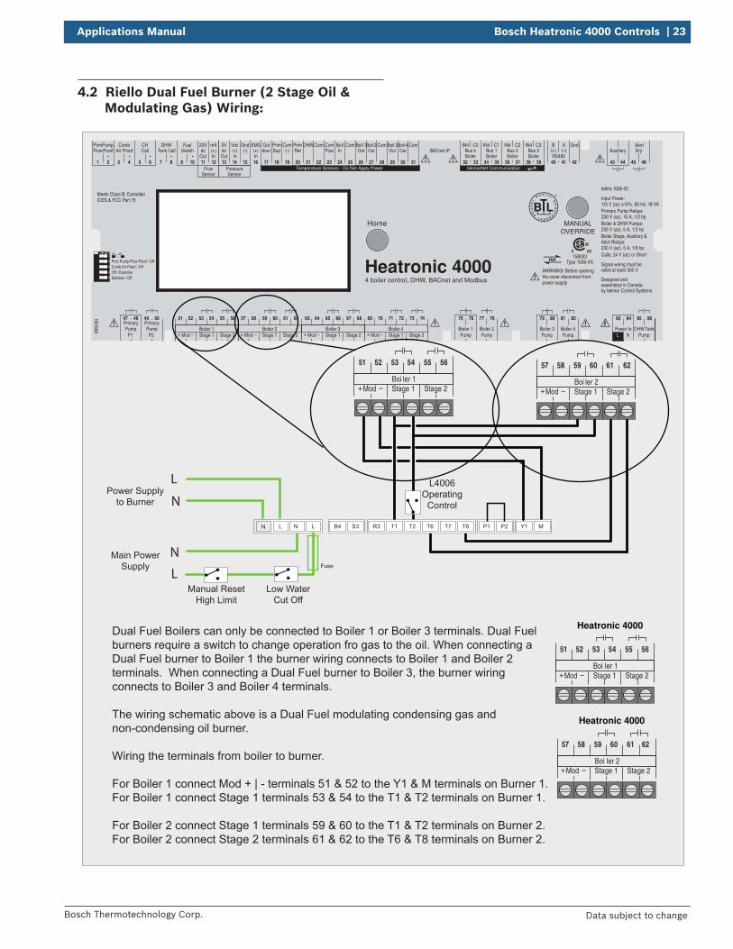
4.2 Riello Dual Fuel Burner (2 Stage Oil & Modulating Gas) Wiring:
12
34
5
Temperature Sensors - Do Not Apply Power tekmarNet Communication
C3C2C0 C1
H6106A Boiler 1
75 76
PumpBoiler 2
77 78
PumpBoiler 3
79 80
PumpBoiler 4
81 82
PumpPower InL N
45 46
Auxiliary
43 44
Pump
47 48
P1Pump
Primary Primary49 50
P2
85 8683 84
20V
11
dc5Vdc
Out In Out In In
Vdc
14
(+) (+)Gnd
15
(-) (-)mA
12 13
(+)EMS
16 17
PrimSup
18
Com
19
PrimRet
BoilIn
20
DHW
21
Com
22 23 24 25
Boil 1Out
26
Boil 2Out
27
ComCom
28
Com
31
Boil 3Out
29
Boil 4Out
30
tN4
32 33
Bus btN4
34 35
Bus 1tN4
36 37
Bus 2tN4
38 39
Bus 3Boiler Boiler Boiler Boiler
PrimPump
1 2
Comb
3 4
Air ProofCH
5 6
CallDHW
7 8
Tank CallFuel
9 10
Switch
FlowSensor
PressureSensor
B A
40 41
BACnet IPRS485
42
Gnd
Prim Pump Flow Proof / OffComb Air Proof / OffOff / ExerciseSetback / Off
51 52
ModBoiler 1
53 54
Stage 1 Stage 2
55 56
+ - Mod Stage 1 Stage 2+ - Mod Stage 1 Stage 2+ - Mod Stage 1 Stage 2+ -
57 58
Boiler 2
59 60 61 62 63 64
Boiler 3
65 66 67 68 69 70
Boiler 4
71 72 73 74
WARNING! Before openingthe cover disconnect frompower supply
Meets Class B: CanadianICES & FCC Part 15
4 boiler control, DHW, BACnet and Modbus
MANUALOVERRIDE
Home
Outdoor
ComFlue
AlertDryFlow Proof
TankDHWPump
(+) (–)
Heatronic 4000158033
Type 1056-XX
tektra 1056-02
Designed and assembled in Canadaby tekmar Control Systems
Signal wiring must be rated at least 300 V.
Input Power: 115 V (ac) ±10%, 60 Hz, 18 VAPrimary Pump Relays: 230 V (ac), 10 A, 1/2 hpBoiler & DHW Pumps: 230 V (ac), 5 A, 1/3 hpBoiler Stage, Auxiliary & Alert Relays: 230 V (ac), 5 A, 1/6 hpCalls: 24 V (ac) or Short
L
Power Supply to Burner
N
B4 S3 R3 T6 T7T1 T2 T8 P1 P2 L N LN
Fuse
Main Power Supply
Y1 M
51 52
ModBoi ler 1
53 54
Stage 1 Stage 2
55 56
+ -
Heatronic 4000
L
NL4006
Operating Control
Dual Fuel Boilers can only be connected to Boiler 1 or Boiler 3 terminals. Dual Fuel burners require a switch to change operation fro gas to the oil. When connecting a Dual Fuel burner to Boiler 1 the burner wiring connects to Boiler 1 and Boiler 2 terminals. When connecting a Dual Fuel burner to Boiler 3, the burner wiring connects to Boiler 3 and Boiler 4 terminals.
The wiring schematic above is a Dual Fuel modulating condensing gas and non-condensing oil burner.
Wiring the terminals from boiler to burner.
For Boiler 1 connect Mod + | - terminals 51 & 52 to the Y1 & M terminals on Burner 1.For Boiler 1 connect Stage 1 terminals 53 & 54 to the T1 & T2 terminals on Burner 1.
For Boiler 2 connect Stage 1 terminals 59 & 60 to the T1 & T2 terminals on Burner 2.For Boiler 2 connect Stage 2 terminals 61 & 62 to the T6 & T8 terminals on Burner 2.
51 52
ModBoi ler 1
53 54
Stage 1 Stage 2
55 56
+ -
57 58
ModBoi ler 2
59 60
Stage 1 Stage 2
61 62
+ -
57 58
ModBoi ler 2
59 60
Stage 1 Stage 2
61 62
+ -
Heatronic 4000
Manual Reset High Limit
Low Water Cut Off
24 | Bosch Heatronic 4000 Controls Applications Manual
Bosch Thermotechnology Corp.Data subject to change
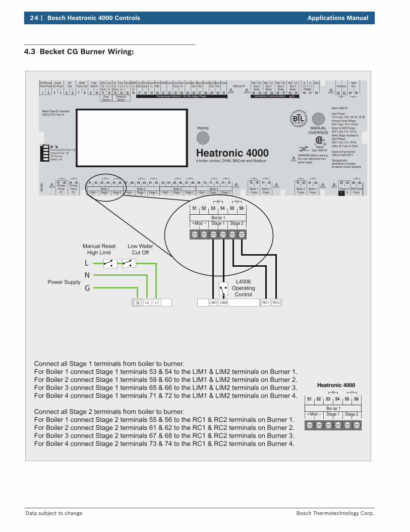
4.3 Becket CG Burner Wiring:
12
34
5
Temperature Sensors - Do Not Apply Power tekmarNet Communication
C3C2C0 C1
H6106A Boiler 1
75 76
PumpBoiler 2
77 78
PumpBoiler 3
79 80
PumpBoiler 4
81 82
PumpPower InL N
45 46
Auxiliary
43 44
Pump
47 48
P1Pump
Primary Primary49 50
P2
85 8683 84
20V
11
dc5Vdc
Out In Out In In
Vdc
14
(+) (+)Gnd
15
(-) (-)mA
12 13
(+)EMS
16 17
PrimSup
18
Com
19
PrimRet
BoilIn
20
DHW
21
Com
22 23 24 25
Boil 1Out
26
Boil 2Out
27
ComCom
28
Com
31
Boil 3Out
29
Boil 4Out
30
tN4
32 33
Bus btN4
34 35
Bus 1tN4
36 37
Bus 2tN4
38 39
Bus 3Boiler Boiler Boiler Boiler
PrimPump
1 2
Comb
3 4
Air ProofCH
5 6
CallDHW
7 8
Tank CallFuel
9 10
Switch
FlowSensor
PressureSensor
B A
40 41
BACnet IPRS485
42
Gnd
Prim Pump Flow Proof / OffComb Air Proof / OffOff / ExerciseSetback / Off
51 52
ModBoiler 1
53 54
Stage 1 Stage 2
55 56
+ - Mod Stage 1 Stage 2+ - Mod Stage 1 Stage 2+ - Mod Stage 1 Stage 2+ -
57 58
Boiler 2
59 60 61 62 63 64
Boiler 3
65 66 67 68 69 70
Boiler 4
71 72 73 74
WARNING! Before openingthe cover disconnect frompower supply
Meets Class B: CanadianICES & FCC Part 15
4 boiler control, DHW, BACnet and Modbus
MANUALOVERRIDE
Home
Outdoor
ComFlue
AlertDryFlow Proof
TankDHWPump
(+) (–)
Heatronic 4000158033
Type 1056-XX
tektra 1056-02
Designed and assembled in Canadaby tekmar Control Systems
Signal wiring must be rated at least 300 V.
Input Power: 115 V (ac) ±10%, 60 Hz, 18 VAPrimary Pump Relays: 230 V (ac), 10 A, 1/2 hpBoiler & DHW Pumps: 230 V (ac), 5 A, 1/3 hpBoiler Stage, Auxiliary & Alert Relays: 230 V (ac), 5 A, 1/6 hpCalls: 24 V (ac) or Short
L
Power Supply
LIM1 LIM2 RC1 RC2 L2 L1G
51 52
ModBoi ler 1
53 54
Stage 1 Stage 2
55 56
+ -
Heatronic 4000
N
GL4006
Operating Control
Connect all Stage 1 terminals from boiler to burner.For Boiler 1 connect Stage 1 terminals 53 & 54 to the LIM1 & LIM2 terminals on Burner 1.For Boiler 2 connect Stage 1 terminals 59 & 60 to the LIM1 & LIM2 terminals on Burner 2.For Boiler 3 connect Stage 1 terminals 65 & 66 to the LIM1 & LIM2 terminals on Burner 3.For Boiler 4 connect Stage 1 terminals 71 & 72 to the LIM1 & LIM2 terminals on Burner 4.
Connect all Stage 2 terminals from boiler to burner.For Boiler 1 connect Stage 2 terminals 55 & 56 to the RC1 & RC2 terminals on Burner 1.For Boiler 2 connect Stage 2 terminals 61 & 62 to the RC1 & RC2 terminals on Burner 2.For Boiler 3 connect Stage 2 terminals 67 & 68 to the RC1 & RC2 terminals on Burner 3.For Boiler 4 connect Stage 2 terminals 73 & 74 to the RC1 & RC2 terminals on Burner 4.
51 52
ModBoi ler 1
53 54
Stage 1 Stage 2
55 56
+ -
Manual Reset High Limit
Low Water Cut Off
Applications Manual Bosch Heatronic 4000 Controls | 25
Bosch Thermotechnology Corp. Data subject to change
4.4 Power Flame Burner Wiring:
12
34
5
Temperature Sensors - Do Not Apply Power tekmarNet Communication
C3C2C0 C1
H6106A Boiler 1
75 76
PumpBoiler 2
77 78
PumpBoiler 3
79 80
PumpBoiler 4
81 82
PumpPower InL N
45 46
Auxiliary
43 44
Pump
47 48
P1Pump
Primary Primary49 50
P2
85 8683 84
20V
11
dc5Vdc
Out In Out In In
Vdc
14
(+) (+)Gnd
15
(-) (-)mA
12 13
(+)EMS
16 17
PrimSup
18
Com
19
PrimRet
BoilIn
20
DHW
21
Com
22 23 24 25
Boil 1Out
26
Boil 2Out
27
ComCom
28
Com
31
Boil 3Out
29
Boil 4Out
30
tN4
32 33
Bus btN4
34 35
Bus 1tN4
36 37
Bus 2tN4
38 39
Bus 3Boiler Boiler Boiler Boiler
PrimPump
1 2
Comb
3 4
Air ProofCH
5 6
CallDHW
7 8
Tank CallFuel
9 10
Switch
FlowSensor
PressureSensor
B A
40 41
BACnet IPRS485
42
Gnd
Prim Pump Flow Proof / OffComb Air Proof / OffOff / ExerciseSetback / Off
51 52
ModBoiler 1
53 54
Stage 1 Stage 2
55 56
+ - Mod Stage 1 Stage 2+ - Mod Stage 1 Stage 2+ - Mod Stage 1 Stage 2+ -
57 58
Boiler 2
59 60 61 62 63 64
Boiler 3
65 66 67 68 69 70
Boiler 4
71 72 73 74
WARNING! Before openingthe cover disconnect frompower supply
Meets Class B: CanadianICES & FCC Part 15
4 boiler control, DHW, BACnet and Modbus
MANUALOVERRIDE
Home
Outdoor
ComFlue
AlertDryFlow Proof
TankDHWPump
(+) (–)
Heatronic 4000158033
Type 1056-XX
tektra 1056-02
Designed and assembled in Canadaby tekmar Control Systems
Signal wiring must be rated at least 300 V.
Input Power: 115 V (ac) ±10%, 60 Hz, 18 VAPrimary Pump Relays: 230 V (ac), 10 A, 1/2 hpBoiler & DHW Pumps: 230 V (ac), 5 A, 1/3 hpBoiler Stage, Auxiliary & Alert Relays: 230 V (ac), 5 A, 1/6 hpCalls: 24 V (ac) or Short
CL1 CL2ES1
Fuse
Main Power Supply
TC+ TC-
51 52
ModBoi ler 1
53 54
Stage 1 Stage 2
55 56
+ -
Heatronic 4000
L4006 Operating
Control
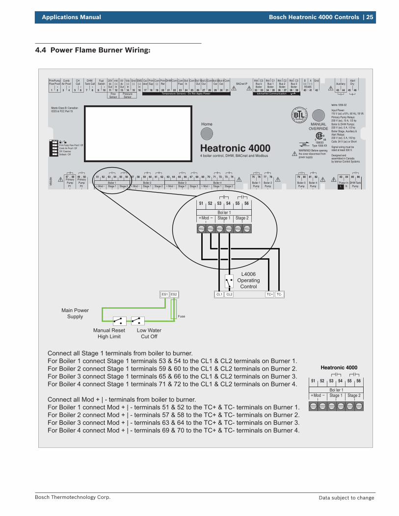
Connect all Stage 1 terminals from boiler to burner.For Boiler 1 connect Stage 1 terminals 53 & 54 to the CL1 & CL2 terminals on Burner 1.For Boiler 2 connect Stage 1 terminals 59 & 60 to the CL1 & CL2 terminals on Burner 2.For Boiler 3 connect Stage 1 terminals 65 & 66 to the CL1 & CL2 terminals on Burner 3.For Boiler 4 connect Stage 1 terminals 71 & 72 to the CL1 & CL2 terminals on Burner 4.
Connect all Mod + | - terminals from boiler to burner.For Boiler 1 connect Mod + | - terminals 51 & 52 to the TC+ & TC- terminals on Burner 1.For Boiler 2 connect Mod + | - terminals 57 & 58 to the TC+ & TC- terminals on Burner 2.For Boiler 3 connect Mod + | - terminals 63 & 64 to the TC+ & TC- terminals on Burner 3.For Boiler 4 connect Mod + | - terminals 69 & 70 to the TC+ & TC- terminals on Burner 4.
51 52
ModBoi ler 1
53 54
Stage 1 Stage 2
55 56
+ -
Manual Reset High Limit
Low Water Cut Off
ES2
26 | Bosch Heatronic 4000 Controls Applications Manual
Bosch Thermotechnology Corp.Data subject to change
4.5 Riello RS Lo/Hi/Lo Burner Wiring:
12
34
5
Temperature Sensors - Do Not Apply Power tekmarNet Communication
C3C2C0 C1
H6106A Boiler 1
75 76
PumpBoiler 2
77 78
PumpBoiler 3
79 80
PumpBoiler 4
81 82
PumpPower InL N
45 46
Auxiliary
43 44
Pump
47 48
P1Pump
Primary Primary49 50
P2
85 8683 84
20V
11
dc5Vdc
Out In Out In In
Vdc
14
(+) (+)Gnd
15
(-) (-)mA
12 13
(+)EMS
16 17
PrimSup
18
Com
19
PrimRet
BoilIn
20
DHW
21
Com
22 23 24 25
Boil 1Out
26
Boil 2Out
27
ComCom
28
Com
31
Boil 3Out
29
Boil 4Out
30
tN4
32 33
Bus btN4
34 35
Bus 1tN4
36 37
Bus 2tN4
38 39
Bus 3Boiler Boiler Boiler Boiler
PrimPump
1 2
Comb
3 4
Air ProofCH
5 6
CallDHW
7 8
Tank CallFuel
9 10
Switch
FlowSensor
PressureSensor
B A
40 41
BACnet IPRS485
42
Gnd
Prim Pump Flow Proof / OffComb Air Proof / OffOff / ExerciseSetback / Off
51 52
ModBoiler 1
53 54
Stage 1 Stage 2
55 56
+ - Mod Stage 1 Stage 2+ - Mod Stage 1 Stage 2+ - Mod Stage 1 Stage 2+ -
57 58
Boiler 2
59 60 61 62 63 64
Boiler 3
65 66 67 68 69 70
Boiler 4
71 72 73 74
WARNING! Before openingthe cover disconnect frompower supply
Meets Class B: CanadianICES & FCC Part 15
4 boiler control, DHW, BACnet and Modbus
MANUALOVERRIDE
Home
Outdoor
ComFlue
AlertDryFlow Proof
TankDHWPump
(+) (–)
Heatronic 4000158033
Type 1056-XX
tektra 1056-02
Designed and assembled in Canadaby tekmar Control Systems
Signal wiring must be rated at least 300 V.
Input Power: 115 V (ac) ±10%, 60 Hz, 18 VAPrimary Pump Relays: 230 V (ac), 10 A, 1/2 hpBoiler & DHW Pumps: 230 V (ac), 5 A, 1/3 hpBoiler Stage, Auxiliary & Alert Relays: 230 V (ac), 5 A, 1/6 hpCalls: 24 V (ac) or Short
L
3 PhaseConnection
N
Other internal wiring of the Riello BurnerB4 S3 R3 T6 T7T1 T2 T8 P1 P2 L1 N LL2
Fuse
Main Power Supply
Y1 M
51 52
ModBoi ler 1
53 54
Stage 1 Stage 2
55 56
+ -
Heatronic 4000
L4006 Operating
Control
Connect all Stage 1 terminals from boiler to burner.For Boiler 1 connect Stage 1 terminals 53 & 54 to the T1 & T2 terminals on Burner 1.For Boiler 2 connect Stage 1 terminals 59 & 60 to the T1 & T2 terminals on Burner 2.For Boiler 3 connect Stage 1 terminals 65 & 66 to the T1 & T2 terminals on Burner 3.For Boiler 4 connect Stage 1 terminals 71 & 72 to the T1 & T2 terminals on Burner 4.
Connect all Stage 2 terminals from boiler to burner.For Boiler 1 connect Stage 2 terminals 55 & 56 to the T6 & T8 terminals on Burner 1.For Boiler 2 connect Stage 2 terminals 61 & 62 to the T6 & T8 terminals on Burner 2.For Boiler 3 connect Stage 2 terminals 67 & 68 to the T6 & T8 terminals on Burner 3.For Boiler 4 connect Stage 2 terminals 73 & 74 to the T6 & T8 terminals on Burner 4.
51 52
ModBoi ler 1
53 54
Stage 1 Stage 2
55 56
+ -
Manual Reset High Limit
Low Water Cut Off
L3
Applications Manual Bosch Heatronic 4000 Controls | 27
Bosch Thermotechnology Corp. Data subject to change
5 Recommended Specifications
The following are the recommended specifications for the Boiler 4000 Control:
f The control shall be capable of sequencing up to four single stage, two stage and modulating boilers, or two dual fuel boilers. Plus a combination of one dual fuel and two single stage, two stage, modulating boilers.
f The control shall be capable of operating combinations of condensing & non-condensing boilers.
f The control shall be capable of adjusting the boiler plant target to provide indirect domestic hot water heating with priority.
f The control shall have the ability to calculate the boiler plant target temperature based on outdoor temperature reset.
f The control shall have the ability to set the boiler plant target temperature using an adjust able setpoint.
f The control shall have the ability to set the boiler plant target temperature as directed by a BAS, BMS or EMS.
f The control shall have an adjustable warm weather shut down applied to outdoor temperature reset operation.
f The control shall be able to operate two primary pumps in standby mode.
f The control shall have the options of a proof demand input or a flow sensor input to prove flow for the primary pump.
f The control shall provide an alert output for flow proof, CA proof & no heat failures.
f The control shall be able to operate one primary pump & one domestic hot water pump during a domestic hot water call.
f The control shall communicate with Modbus®, BACnet® IP & tekmarNet® systems to provide remote monitoring & adjustment.
f The control shall have the ability to display the current temperature difference between the return temperature & the supply temperature, ΔT.
f The control shall have the option to measure fluid pressure & flow rates.
f The control shall have an option to rotate the boilers & primary pumps based on the accumulated running hours.
f The control shall display the run time of the boilers & optionally, primary pumps.
f The control shall use proportional, integral & derivative (PID) logic when modulating the boilers.
f The control shall have the option to modulate the boilers sequentially or in parallel.
f The control shall have an adjustable minimum supply water temperature setting to help prevent condensation of flue gases & subsequent corrosion & blockage of the boiler’s heat exchanger & chimney.
f The control shall have the option of an automatic differential calculation in order to prevent short cycling of the boilers.
f The control shall have the ability to operate individual boiler pumps.
f The control shall have adjustable post purge settings that allow the primary & boiler pumps to run for a set period after the boiler has been shut off.
f The control shall have the option for fixed lead & fixed last boiler rotation.
f The control shall have the option to prove & operate a combustion air damper output.
f The control shall have an adjustable minimum inter-stage delay that can be set manually or calculated by the control.
f The control shall have the option of accepting a 0 – 10 V (dc) or 2 – 10 V (dc) input signal from an energy manage-ment system with an adjustable offset.
f The control shall have three separate lockable access levels (Advanced, Installer, User) to limit the number of setting adjustments available to various users.
f The control shall have manual override options to test boiler & pump operation, suspend boiler plant operation, operate pumps for purging & operate the system with a maximum heat output.
f The control shall have the ability to display the current outdoor, boiler supply, return & inlet temperatures.
f The control shall continually monitor the temperature sensors & provide an error message upon a control or sensor failure.
f During extended periods of inactivity, all pumps shall be periodically exercised to prevent seizure during long idle periods.
f The control shall include a setback schedule that can be used by the control itself or shared with other tN4 devices.
f The control shall have the option to operate as a tN4 system control with a tN4 boiler bus.
f The control shall display the current % modulation of each boiler, or the number of stages fired.
f The control shall include an adjustment for the cycle length if connected to a tN4 network.

United States and Canada
Bosch Thermotechnology Corp.50 Wentworth AvenueLondonderry, NH 03053
Tel: 1-800-283-3787Fax: 1-603-965-7581www.bosch-climate.us
BTC 461501101 A / 6720810373 / 10.2014