Embed Size (px)
Citation preview

Collision Avoidance System CAS-M light
Manual
V 1.10, 2/14/2017

Table of contents
1 System Overview ................................................................................................................................................. 31.1 Function principle ........................................................................................................................................................................... 31.2 Hardware ............................................................................................................................................................................................ 31.3 Wiring .................................................................................................................................................................................................. 41.4 CAN communication ...................................................................................................................................................................... 5
2 Installation Guide ................................................................................................................................................ 72.1 Mounting the radar sensor .......................................................................................................................................................... 72.2 Configuration of the sensor position ...................................................................................................................................... 82.3 Configuration of the system threshold values ..................................................................................................................... 9
3 Using the CAS-M light Information ................................................................................................................ 103.1 Predefined messages ................................................................................................................................................................... 103.2 Using raw values ............................................................................................................................................................................ 10
4 Packages ............................................................................................................................................................. 114.1 CAS-M light & connector (500 kBaud) ................................................................................................................................. 114.2 CAS-M light & connector (1 MBaud) .................................................................................................................................... 114.3 CAS-M light incl. DDU 9 (500 kBaud) .................................................................................................................................... 114.4 CAS-M light incl. DDU 9 (1 MBaud) ....................................................................................................................................... 11
5 Open-end Loom ................................................................................................................................................. 12
6 Appendix ............................................................................................................................................................ 13
Table of Contents
2 / 26 Collision Avoidance System CAS-M light Bosch Motorsport

System OverviewThe CAS-M light helps the driver to focus on the track and warns him if a car isapproaching from behind. The system provides information about relative speedand distance on the CAN bus. The benefit is even more increased during night-time or in bad weather conditions.
The interface is very intuitive and adaptable to the drivers liking – so there is noneed in special driver trainings.
Function principleCAS-M light provides information for distance and relative speed of the closestvehicle behind via two LEDs (left and right) in the driver display. Only the closestvehicle behind is considered. All other objects are suppressed.
In large (green) and medium (yellow) distance both LEDs (left and right) are usedin parallel to provide the available information. In close (red) distance a left/rightdetermination is done, and only the appropriate left or right LED is used to pro-vide information about the object behind the driver.
All distance and delta speed thresholds based on the physical raw values to con-trol the object detection and LED visualization can be adjusted individually viaCAN (depending on pilot and race category different settings may be required).
CAS-M light contains a pre-defined visualization concept to allow for a quickstarting with the system. The pre-defined thresholds are based on Bosch Motor-sport know how and experience with the system.
HardwareThe CAS-M light system consists of a Bosch automotive mid range radar sensor,shown in the following picture/drawing.
Fig. 1: CAS-M light sensor
1
1.1
1.2
System Overview | 1
Bosch Motorsport Collision Avoidance System CAS-M light 3 / 26
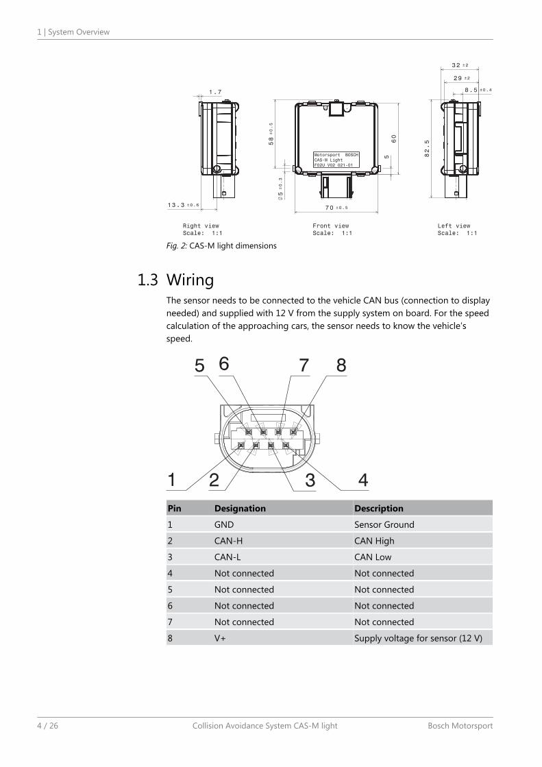
Fig. 2: CAS-M light dimensions
WiringThe sensor needs to be connected to the vehicle CAN bus (connection to displayneeded) and supplied with 12 V from the supply system on board. For the speedcalculation of the approaching cars, the sensor needs to know the vehicle’sspeed.
Pin Designation Description
1 GND Sensor Ground
2 CAN-H CAN High
3 CAN-L CAN Low
4 Not connected Not connected
5 Not connected Not connected
6 Not connected Not connected
7 Not connected Not connected
8 V+ Supply voltage for sensor (12 V)
1.3
1 | System Overview
4 / 26 Collision Avoidance System CAS-M light Bosch Motorsport

Car CAS-M
Vehicle speed, configuration
LED status
Fig. 3: Wiring schematic
CAN communicationSince the system provides the information on the CAN bus (car approaching left/right, distances, relative speeds ...), it is mandatory to connect the sensor to it. Inaddition the sensor needs to get the vehicle’s speed via CAN.
CAN Baud rate: 500 kBaud or 1 MBaud
CAN update rate of Sensor: 50 Hz
Vehicle SpeedInformation that needs to be send from the car to the system:
Message CAN ID Byteorder
Valuetype
Startbit
Length[bit]
Factor Offset
Speed 0x616 Intel Un-signed
24 16 0.1 0
Predefined MessagesInformation that is send from the sensor to the car:
Message CAN ID Byteorder
Valuetype
Startbit
Length[bit]
Factor Offset
Object_left_dist_range
0x3F3 Intel Un-signed
58 3 1 0
Object_left_ap-proach_spd_range
0x3F3 Intel Un-signed
61 3 1 0
Object_right_dist_range
0x3F5 Intel Un-signed
58 3 1 0
1.4
System Overview | 1
Bosch Motorsport Collision Avoidance System CAS-M light 5 / 26

Message CAN ID Byteorder
Valuetype
Startbit
Length[bit]
Factor Offset
Object_right_ap-proach_spd_range
0x3F5 Intel Un-signed
61 3 1 0
Raw valuesInformation that is send from the sensor to the car:
Message CAN ID Byteorder
Valuetype
Startbit
Length[bit]
Factor Offset
Object_left_dx 0x3F3 Intel Un-signed
0 12 0.0625 0
Object_left_vx 0x3F3 Intel Signed 12 12 0.0625 0
Object_left_dy 0x3F3 Intel Signed 24 14 0.015625 0
Ob-ject_right_dx
0x3F5 Intel Un-signed
0 12 0.0625 0
Object_right_vx 0x3F5 Intel Signed 12 12 0.0625 0
Ob-ject_right_dy
0x3F5 Intel Signed 24 14 0.015625 0
Important noteDo not use the messages 0xB9, 0x757 or 0x7C1 on the sensor CAN. These Mes-sages are not needed but if used the sensor will be affected.
The sensor sends the additional message 0xB9 on the CAN. This message is notneeded for the CAS-M light system but already used by the sensor.
1 | System Overview
6 / 26 Collision Avoidance System CAS-M light Bosch Motorsport

Installation Guide
Mounting the radar sensorA mounting frame with 4xM6 threaded bushings are delivered with the sensor.An individual concept for each car mounting situation must be developed by thecar manufacturer. The following mounting restrictions must be fulfilled to securea proper function of the system.
▪ The radar sensor must be longitudinally and laterally leveled, aligned with thevehicle’s longitudinal axis and mounted on the vehicle’s lateral centerline.Sensor mounting height of 20 cm to 90 cm off the ground will ensure maxi-mum range.If a mounting in the vehicle centre line is not possible, the offset must beconfigured via the appropriate CAN message (see chapter Configuration ofthe sensor position [} 8]).
▪ The sensor may be mounted flush mounted with the rear fascia.
▪ It is critical that the radar sensor has an unobstructed (or radar-transparent)view out the rear of the vehicle. Optimum is a mounting without any materialin front of the sensor.If it must be mounted behind, the plane in front of the sensor surface mustbe free of conductive materials (e.g. a thin layer of vinyl, fiberglass or Kevlar).The distance between sensor and surface depends on the used material andshould be approximately 5 mm.
Fig. 4: CAS-M light frame
2
2.1
Installation Guide | 2
Bosch Motorsport Collision Avoidance System CAS-M light 7 / 26

Configuration of the sensor position
Definition of sensor position and orientation
Message CAN ID Byteorder
Valuetype
Startbit
Length[bit]
Factor Offset
Orientation 0x618 Intel Signed 28 2 1 0
Position_X 0x618 Intel Signed 30 10 0.01 0
Position_Y 0x618 Intel Signed 40 8 0.01 0
Position_Z 0x618 Intel Unsigned 48 8 0.01 0
The Message 0x620 has to be send to the sensor once after every power cycle.Otherwise the default values are used by the sensor.
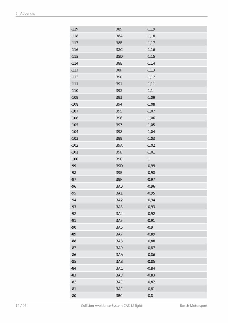
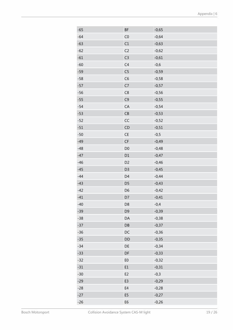
See appendix table 1 for assignment of signed integer values in hex.
Conversion of negative values into hex with two´s complement:
10 bit: Hex value = Decimal to hex (Physical value / Factor + 1024)
8 bit: Hex value = Decimal to hex (Physical value / Factor + 256)
Example for Position X (10 Bit value) = -1 m
Decimal value = -1 / 0.01 + 1024 = 954
Hex value = Decimal to hex (954) = 39C
Orientation
Description Value Default
Connector facing up -1 1
Connector facing down +1
Position_X
Description Comment Default
Sensor position in X direction Distance from rear axle [m]X-axis is positive in drivingdirection
-1
Position_Y
Description Comment Default
Sensor position in Y direction Distance from vehicle sym-metry axle [m]Left is positive
0
Position_Z
Description Comment Default
Sensor position in Z direction Distance to ground [m] 0.5
2.2
2 | Installation Guide
8 / 26 Collision Avoidance System CAS-M light Bosch Motorsport

Configuration of the system threshold values
Fig. 5: Distance schematic
Message CAN ID Byteorder
Valuetype
Startbit
Length[bit]
Factor Offset
Distance_Near 0x620 Intel Unsigned 0 8 1 0
Distance_Medium 0x620 Intel Unsigned 8 8 1 0
Distance_Far 0x620 Intel Unsigned 16 8 1 0
Speed_medium 0x620 Intel Unsigned 24 8 1 0
Speed-high 0x620 Intel Unsigned 32 8 1 0
Distance thresholds
Description Comment Default
Distance_Near Threshold between near range and mediumrange [m]
12
Distance_Medi-um
Threshold between medium range and farrange
30
Distance_Far Threshold between far range and out of range(no warning)
75
Speed thresholds
Description Comment Default
Speed_medium Speed of approaching vehicle [km/h] for lowfrequency flashing
7.2
Speed_high Speed of approaching vehicle [km/h] for highfrequency flashing
14.4
2.3
Installation Guide | 2
Bosch Motorsport Collision Avoidance System CAS-M light 9 / 26

Using the CAS-M light Information
Predefined messagesThe system provides predefined CAN-messages with evaluated values for dis-tance and relative speed.
Configuration distanceObject_left/right_dist_range defines the distance of the car behind into a color foran LED.
Value Color Description
0x0 off inactive
0x1 green large distance
0x2 yellow medium distance
0x4 red close distance
Configuration relative speedObject_left/right_approach_spd_range defines the relative speed of the car behindinto a blinking frequency for an LED.
Value LED-Status Description
0x0 off inactive
0x1 LED on low relative speed
0x2 LED flash low frequency medium relative speed
0x4 LED flash high frequency high relative speed
Using raw valuesAs an alternative to the predefined messages it is possible to use the raw valuesprovided by the system. Every value is provided for each side (left and right).
Object_left/right_dxDistance to the car behind [m]
Object_left/right_vxRelative speed of the car behind [m/s]
Object_left/right_dyPosition of the car behind (relating to the mid axis of the car) [m]
3
3.1
3.1.1
3.1.2
3.2
3 | Using the CAS-M light Information
10 / 26 Collision Avoidance System CAS-M light Bosch Motorsport

Packages
CAS-M light & connector (500 kBaud)The CAS-M light system can be ordered without loom and display. The systemincludes:
▪ CAS-M light sensor with 500 kBaud CAN speed & mating connector
Part number: F 02U V02 021-01
CAS-M light & connector (1 MBaud)The CAS-M light system can be ordered without loom and display. The systemincludes:
▪ CAS-M light sensor with 1 MBaud CAN speed & mating connector
Part number: F 02U V02 220-01
CAS-M light incl. DDU 9 (500 kBaud)The CAS-M light system can be ordered directly with a DDU 9. The system in-cludes:
▪ CAS-M light sensor with 500 kBaud CAN speed & mating connector
▪ DDU 9
Part number: F 02U V02 591-01
CAS-M light incl. DDU 9 (1 MBaud)The CAS-M light system can be ordered directly with a DDU 9. The system in-cludes:
▪ CAS-M light sensor with 1 MBaud CAN speed & mating connector
▪ DDU 9
Part number: F 02U V02 592-01
4
4.1
4.2
4.3
4.4
Packages | 4
Bosch Motorsport Collision Avoidance System CAS-M light 11 / 26

Open-end LoomThe open end loom can be used to connect the sensor to an existing display unit.The loom is compatible with the CAS-M light packages F 02U V02 021-01 and F02U V02 220-01.
The loom includes:
▪ Sensor matting connector F 037 B00 168-01
▪ Removable 120 Ω terminating resistor
▪ Open end loom for display unit
Part number: F 02U V02 105-01
5
5 | Open-end Loom
12 / 26 Collision Avoidance System CAS-M light Bosch Motorsport

AppendixOrientation
Decimal Hex Physical
-1 3 -1
1 1 1
Position X
Decimal Hex Physical [m]
-150 36A -1,5
-149 36B -1,49
-148 36C -1,48
-147 36D -1,47
-146 36E -1,46
-145 36F -1,45
-144 370 -1,44
-143 371 -1,43
-142 372 -1,42
-141 373 -1,41
-140 374 -1,4
-139 375 -1,39
-138 376 -1,38
-137 377 -1,37
-136 378 -1,36
-135 379 -1,35
-134 37A -1,34
-133 37B -1,33
-132 37C -1,32
-131 37D -1,31
-130 37E -1,3
-129 37F -1,29
-128 380 -1,28
-127 381 -1,27
-126 382 -1,26
-125 383 -1,25
-124 384 -1,24
-123 385 -1,23
-122 386 -1,22
-121 387 -1,21
-120 388 -1,2
6
Appendix | 6
Bosch Motorsport Collision Avoidance System CAS-M light 13 / 26
-119 389 -1,19
-118 38A -1,18
-117 38B -1,17
-116 38C -1,16
-115 38D -1,15
-114 38E -1,14
-113 38F -1,13
-112 390 -1,12
-111 391 -1,11
-110 392 -1,1
-109 393 -1,09
-108 394 -1,08
-107 395 -1,07
-106 396 -1,06
-105 397 -1,05
-104 398 -1,04
-103 399 -1,03
-102 39A -1,02
-101 39B -1,01
-100 39C -1
-99 39D -0,99
-98 39E -0,98
-97 39F -0,97
-96 3A0 -0,96
-95 3A1 -0,95
-94 3A2 -0,94
-93 3A3 -0,93
-92 3A4 -0,92
-91 3A5 -0,91
-90 3A6 -0,9
-89 3A7 -0,89
-88 3A8 -0,88
-87 3A9 -0,87
-86 3AA -0,86
-85 3AB -0,85
-84 3AC -0,84
-83 3AD -0,83
-82 3AE -0,82
-81 3AF -0,81
-80 3B0 -0,8
6 | Appendix
14 / 26 Collision Avoidance System CAS-M light Bosch Motorsport

-79 3B1 -0,79
-78 3B2 -0,78
-77 3B3 -0,77
-76 3B4 -0,76
-75 3B5 -0,75
-74 3B6 -0,74
-73 3B7 -0,73
-72 3B8 -0,72
-71 3B9 -0,71
-70 3BA -0,7
-69 3BB -0,69
-68 3BC -0,68
-67 3BD -0,67
-66 3BE -0,66
-65 3BF -0,65
-64 3C0 -0,64
-63 3C1 -0,63
-62 3C2 -0,62
-61 3C3 -0,61
-60 3C4 -0,6
-59 3C5 -0,59
-58 3C6 -0,58
-57 3C7 -0,57
-56 3C8 -0,56
-55 3C9 -0,55
-54 3CA -0,54
-53 3CB -0,53
-52 3CC -0,52
-51 3CD -0,51
-50 3CE -0,5
-49 3CF -0,49
-48 3D0 -0,48
-47 3D1 -0,47
-46 3D2 -0,46
-45 3D3 -0,45
-44 3D4 -0,44
-43 3D5 -0,43
-42 3D6 -0,42
-41 3D7 -0,41
-40 3D8 -0,4
Appendix | 6
Bosch Motorsport Collision Avoidance System CAS-M light 15 / 26

-39 3D9 -0,39
-38 3DA -0,38
-37 3DB -0,37
-36 3DC -0,36
-35 3DD -0,35
-34 3DE -0,34
-33 3DF -0,33
-32 3E0 -0,32
-31 3E1 -0,31
-30 3E2 -0,3
-29 3E3 -0,29
-28 3E4 -0,28
-27 3E5 -0,27
-26 3E6 -0,26
-25 3E7 -0,25
-24 3E8 -0,24
-23 3E9 -0,23
-22 3EA -0,22
-21 3EB -0,21
-20 3EC -0,2
-19 3ED -0,19
-18 3EE -0,18
-17 3EF -0,17
-16 3F0 -0,16
-15 3F1 -0,15
-14 3F2 -0,14
-13 3F3 -0,13
-12 3F4 -0,12
-11 3F5 -0,11
-10 3F6 -0,1
-9 3F7 -0,09
-8 3F8 -0,08
-7 3F9 -0,07
-6 3FA -0,06
-5 3FB -0,05
-4 3FC -0,04
-3 3FD -0,03
-2 3FE -0,02
-1 3FF -0,01
0 0 0
6 | Appendix
16 / 26 Collision Avoidance System CAS-M light Bosch Motorsport

1 1 0,01
2 2 0,02
3 3 0,03
4 4 0,04
5 5 0,05
6 6 0,06
7 7 0,07
8 8 0,08
9 9 0,09
10 A 0,1
11 B 0,11
12 C 0,12
13 D 0,13
Position Y
Decimal Hex Physical [m]
-128 80 -1,28
-127 81 -1,27
-126 82 -1,26
-125 83 -1,25
-124 84 -1,24
-123 85 -1,23
-122 86 -1,22
-121 87 -1,21
-120 88 -1,2
-119 89 -1,19
-118 8A -1,18
-117 8B -1,17
-116 8C -1,16
-115 8D -1,15
-114 8E -1,14
-113 8F -1,13
-112 90 -1,12
-111 91 -1,11
-110 92 -1,1
-109 93 -1,09
-108 94 -1,08
-107 95 -1,07
-106 96 -1,06
Appendix | 6
Bosch Motorsport Collision Avoidance System CAS-M light 17 / 26

-105 97 -1,05
-104 98 -1,04
-103 99 -1,03
-102 9A -1,02
-101 9B -1,01
-100 9C -1
-99 9D -0,99
-98 9E -0,98
-97 9F -0,97
-96 A0 -0,96
-95 A1 -0,95
-94 A2 -0,94
-93 A3 -0,93
-92 A4 -0,92
-91 A5 -0,91
-90 A6 -0,9
-89 A7 -0,89
-88 A8 -0,88
-87 A9 -0,87
-86 AA -0,86
-85 AB -0,85
-84 AC -0,84
-83 AD -0,83
-82 AE -0,82
-81 AF -0,81
-80 B0 -0,8
-79 B1 -0,79
-78 B2 -0,78
-77 B3 -0,77
-76 B4 -0,76
-75 B5 -0,75
-74 B6 -0,74
-73 B7 -0,73
-72 B8 -0,72
-71 B9 -0,71
-70 BA -0,7
-69 BB -0,69
-68 BC -0,68
-67 BD -0,67
-66 BE -0,66
6 | Appendix
18 / 26 Collision Avoidance System CAS-M light Bosch Motorsport
-65 BF -0,65
-64 C0 -0,64
-63 C1 -0,63
-62 C2 -0,62
-61 C3 -0,61
-60 C4 -0,6
-59 C5 -0,59
-58 C6 -0,58
-57 C7 -0,57
-56 C8 -0,56
-55 C9 -0,55
-54 CA -0,54
-53 CB -0,53
-52 CC -0,52
-51 CD -0,51
-50 CE -0,5
-49 CF -0,49
-48 D0 -0,48
-47 D1 -0,47
-46 D2 -0,46
-45 D3 -0,45
-44 D4 -0,44
-43 D5 -0,43
-42 D6 -0,42
-41 D7 -0,41
-40 D8 -0,4
-39 D9 -0,39
-38 DA -0,38
-37 DB -0,37
-36 DC -0,36
-35 DD -0,35
-34 DE -0,34
-33 DF -0,33
-32 E0 -0,32
-31 E1 -0,31
-30 E2 -0,3
-29 E3 -0,29
-28 E4 -0,28
-27 E5 -0,27
-26 E6 -0,26
Appendix | 6
Bosch Motorsport Collision Avoidance System CAS-M light 19 / 26

-25 E7 -0,25
-24 E8 -0,24
-23 E9 -0,23
-22 EA -0,22
-21 EB -0,21
-20 EC -0,2
-19 ED -0,19
-18 EE -0,18
-17 EF -0,17
-16 F0 -0,16
-15 F1 -0,15
-14 F2 -0,14
-13 F3 -0,13
-12 F4 -0,12
-11 F5 -0,11
-10 F6 -0,1
-9 F7 -0,09
-8 F8 -0,08
-7 F9 -0,07
-6 FA -0,06
-5 FB -0,05
-4 FC -0,04
-3 FD -0,03
-2 FE -0,02
-1 FF -0,01
0 0 0
1 1 0,01
2 2 0,02
3 3 0,03
4 4 0,04
5 5 0,05
6 6 0,06
7 7 0,07
8 8 0,08
9 9 0,09
10 A 0,1
11 B 0,11
12 C 0,12
13 D 0,13
14 E 0,14
6 | Appendix
20 / 26 Collision Avoidance System CAS-M light Bosch Motorsport

15 F 0,15
16 10 0,16
17 11 0,17
18 12 0,18
19 13 0,19
20 14 0,2
21 15 0,21
22 16 0,22
23 17 0,23
24 18 0,24
25 19 0,25
26 1A 0,26
27 1B 0,27
28 1C 0,28
29 1D 0,29
30 1E 0,3
31 1F 0,31
32 20 0,32
33 21 0,33
34 22 0,34
35 23 0,35
36 24 0,36
37 25 0,37
38 26 0,38
39 27 0,39
40 28 0,4
41 29 0,41
42 2A 0,42
43 2B 0,43
44 2C 0,44
45 2D 0,45
46 2E 0,46
47 2F 0,47
48 30 0,48
49 31 0,49
50 32 0,5
51 33 0,51
52 34 0,52
53 35 0,53
54 36 0,54
Appendix | 6
Bosch Motorsport Collision Avoidance System CAS-M light 21 / 26

55 37 0,55
56 38 0,56
57 39 0,57
58 3A 0,58
59 3B 0,59
60 3C 0,6
61 3D 0,61
62 3E 0,62
63 3F 0,63
64 40 0,64
65 41 0,65
66 42 0,66
67 43 0,67
68 44 0,68
69 45 0,69
70 46 0,7
71 47 0,71
72 48 0,72
73 49 0,73
74 4A 0,74
75 4B 0,75
76 4C 0,76
77 4D 0,77
78 4E 0,78
79 4F 0,79
80 50 0,8
81 51 0,81
82 52 0,82
83 53 0,83
84 54 0,84
85 55 0,85
86 56 0,86
87 57 0,87
88 58 0,88
89 59 0,89
90 5A 0,9
91 5B 0,91
92 5C 0,92
93 5D 0,93
94 5E 0,94
6 | Appendix
22 / 26 Collision Avoidance System CAS-M light Bosch Motorsport

95 5F 0,95
96 60 0,96
97 61 0,97
98 62 0,98
99 63 0,99
100 64 1
101 65 1,01
102 66 1,02
103 67 1,03
104 68 1,04
105 69 1,05
106 6A 1,06
107 6B 1,07
108 6C 1,08
109 6D 1,09
110 6E 1,1
111 6F 1,11
112 70 1,12
113 71 1,13
114 72 1,14
115 73 1,15
116 74 1,16
117 75 1,17
118 76 1,18
119 77 1,19
120 78 1,2
121 79 1,21
122 7A 1,22
123 7B 1,23
124 7C 1,24
125 7D 1,25
126 7E 1,26
127 7F 1,27
Appendix | 6
Bosch Motorsport Collision Avoidance System CAS-M light 23 / 26


Bosch Engineering North AmericaMotorsports38000 Hills Tech DriveFarmington Hills, MI 48331-3417United States of Americawww.bosch-motorsport.com