Embed Size (px)
DESCRIPTION
Wireless Test Instrumentation for Rotating Parts. ECE 193 Advisor: Rajeev Bansal Olivia Bonner David Vold Brendon Rusch Michael Grogan ME 32 Advisor: Robert Gao Kyle Lindell Andrew Potrepka. Sikorsky Contacts. Company Advisor: Paul Inguanti [email protected] - PowerPoint PPT Presentation
Citation preview

Wireless Test Instrumentation for Rotating Parts
ECE 193 Advisor: Rajeev BansalOlivia Bonner
David VoldBrendon Rusch
Michael GroganME 32 Advisor: Robert Gao
Kyle LindellAndrew Potrepka

Sikorsky Contacts
Company Advisor: Paul Inguanti
Senior Test Engineer: Chris Winslow
Test Instrumentation Engineer: Daniel Messner

Company Background The Problem System Requirements 2012-2013 Team Design Design Challenges Project Goals Timeline Budget
Outline

Sikorsky Aircraft Company:
- Founded in 1925 by Igor Sikorsky in Roosevelt, NY
- Owned by United Technologies Company (UTC)
- Moved to Stratford, CT in 1929
- Produces aircraft and helicopters
- Well known models: UH-60 Blackhawk and SH-60 Seahawk
Company Background

Produced 30 military and 10 commercial helicopters in the first quarter of 2013
Generated $6.8 Billion [2012-2013] in net-sales
Serves 25 governments world-wide
Used in all 5 U.S. military branches
Saved close to 2 million lives since first helicopter rescue mission in 1944
Company Background

S-92 helicopter has four blade, twin engines with a medium lift- Used for search and rescue
S-92 aircraft elements need monitoring:- gearboxes, control systems, rotor blades, powertrain element
Company Background

Wired sensors have several inefficiencies:- The components are heavy
- The wires break
- The connectors fail
- Slip rings are needed for rotating components
The Problem

A wireless sensor network is a possible solution to the problems of a wired system.
Benefits of a Wireless System:- No long, heavy wires- No slip rings- Overall weight of system reduced
The Problem

Challenges of a Wireless System:- Powering system- Large Temperature Range
-65ºF to 400ºF
The team’s goal is to find solutions to these challenges through research and testing.
The Problem
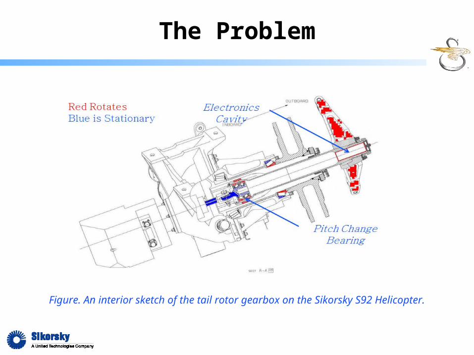
Figure. An interior sketch of the tail rotor gearbox on the Sikorsky S92 Helicopter.
The Problem

Figure. Exterior view of the tail rotor, (where the electrics cavity is located).
The Problem

The team must complete the following project requirements:- Monitor the bearing:
Temperature, Vibration, or Strain Process the measured data:
- Fast Fourier Transform (FFT) or Band Pass Filter (BPF)- Digitize and compress the data for storage
Temporarily store the measured data Transmit the data to a stationary system for long term storage
and analysis- Data must travel wirelessly upwards of 40 feet
System Requirements
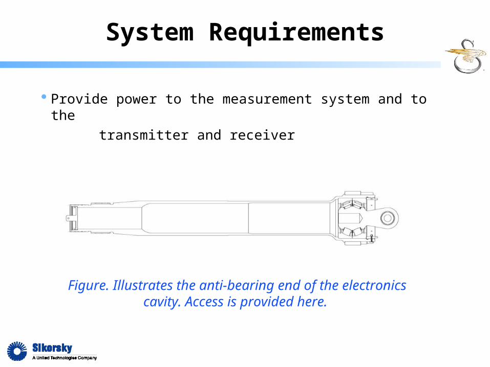
Provide power to the measurement system and to the
transmitter and receiver
System Requirements
Figure. Illustrates the anti-bearing end of the electronics cavity. Access is provided here.

Electronics Compartment:- Size: 1.5” diameter x 5.1” long- Temperature Range: -65ºF to 300ºF
Sensor(s):- Minimum of 2 sensor types- Temperature Range: -65ºF to 400ºF
Rotating Speed of Tail Rotor Shaft:- 1200 RPM
System Requirements

Battery Life:- 1 year min (3 years recommended)- Must run for 12 hours a day and survive a 30 day period of
inactivity
Energy Harvesting- Thermoelectric (Thermocouple)- Vibrational (Piezoelectric)- Magnetic (Alternator)
System Requirements

Environmental Parameters:
- Exterior hostile environment (maintain system internally)
- Cavity is lubricated with oil
- Moisture expected
- High vibration level expected
System Requirements
Accelerometer, microcontroller, transceiver, and lithium battery mounted in the electronics compartment
- One sensor- Signal quality needs improvement- Some components in need of replacement
Mounted on lathe-like test rig- Bearings need replacement
2012-2013 Team Design

2012-2013 Team Design
Figure. Test Rig from 2012-2013 team.

Figure. System block diagram from 2012-2013 team.
2012-2013 Team Design

ECE: - Sensor selection (at least two different sensors)- Signal analysis, storage, and transmission- Ensure sufficiently clean signal- Battery selection and power management
ME:- Energy harvesting/energy generation to power/recharge
system- Repair and improvement of last year’s test rig- Mounting and installation of sensors and transmitter
Project Goals
Project Goals
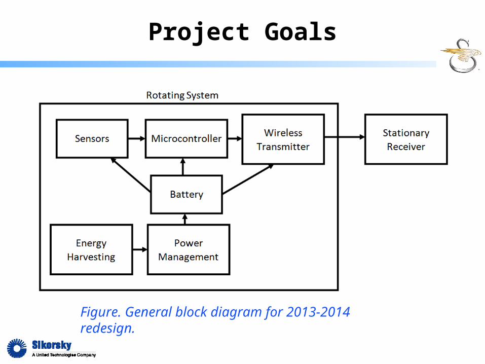
Figure. General block diagram for 2013-2014 redesign.

Timeline
Period Highlight: 6
Plan
Actual
% Complete
Actual (beyond plan)
% Complete (beyond plan)
Semester 1Semester 2
PLAN PLAN ACTUAL ACTUAL PERCENT September October November December JanuaryFebruary March April
ACTIVITY START DURATION START DURATION COMPLETE Weeks
1 2 3 4 5 6 7 8 9 10 11 12 13 14 15 16 17 18 19 20 21 22 23 24 25 26 27 28 29 30 31 32 33 34 35
Project Statement 1 4 1 4100%
Research 2 10 2 510%
Design 8 7
Component selection 12 3
Purchasing 13 3
Prototype Build 16 8
Testing 24 5
Debugging 28 5
Final Presentations 32 4

Budget funds from Sikorsky: $2,000
Re-use Mechanical components from last year.
Estimated Electronics costsfrom last year’s expenses: $2,129.36
Budget deficit: $129.36
Budget

Which sensors should be used?
Will data processing be accomplished at the transmitter or receiver end?
Which energy harvesting technique will be best for this application?
What is the power envelope of the full electronics package?
Can we deliver that power through energy harvesting?
Mission Questions
Please vote with your iClicker based on the three criteria:
- Grade: A, B, or C
Questions?