Embed Size (px)
Citation preview
Wireless Networks for Multi-Robot Communications Team
Senior Design Project
Clay Oehlke • Matt Crotts • Kenny McNutt • Jeremy Vernon
05/05/2003
- 1 -
Table of Contents 1. Implementation Notes .......................................................................................................................................................................... 3
1.1 Introduction ...................................................................................................................................................................................... 3 1.2 Global Variables ............................................................................................................................................................................... 3
Byte ....................................................................................................................................................................................................... 3 1.2.1 Token...................................................................................................................................................................................... 3 1.2.2 Found ..................................................................................................................................................................................... 4 1.2.3 NextNode................................................................................................................................................................................ 4 1.2.4 Route Table ............................................................................................................................................................................ 4 1.2.5 Invite ...................................................................................................................................................................................... 4 1.2.6 ID ........................................................................................................................................................................................... 4
1.3 Finite State Machine......................................................................................................................................................................... 5 1.3.1 Initialization........................................................................................................................................................................... 5 1.3.2 Joining ................................................................................................................................................................................... 5 1.3.3 Inviting ................................................................................................................................................................................... 6 1.3.4 Idle (Search Algorithm).......................................................................................................................................................... 6 1.3.5 Monitoring ............................................................................................................................................................................. 7 1.3.6 Have Token ............................................................................................................................................................................ 7
1.4 Code Outline..................................................................................................................................................................................... 7 1.4.1 init.bsp.................................................................................................................................................................................... 8 1.4.2 mainRoutine.bsp..................................................................................................................................................................... 8 1.4.3 TxRoutine.bsp......................................................................................................................................................................... 8 1.4.4 RxRoutine.bsp ........................................................................................................................................................................ 9 1.4.5 dance.bsp ............................................................................................................................................................................... 9
1.5 Hardware ........................................................................................................................................................................................ 10 1.5.1 Servos................................................................................................................................................................................... 10 1.5.2 Infrared circuit ..................................................................................................................................................................... 10 1.5.3 Photo resistors ..................................................................................................................................................................... 11 1.5.4 Radio Frequency Transmitter, Receiver, and Antennas....................................................................................................... 12
2. User’s Manual .................................................................................................................................................................................... 13 2.1 Introduction .................................................................................................................................................................................... 13 2.2 Activating the Robots ..................................................................................................................................................................... 13 2.3 Running the Search......................................................................................................................................................................... 15
3. Course Debriefing .............................................................................................................................................................................. 16 3.1 Group Management ........................................................................................................................................................................ 16 3.2 Safety and Ethical Concerns ........................................................................................................................................................... 16 3.3 Final Analysis of Solution .............................................................................................................................................................. 16 3.4 Interference from the Servo Motors................................................................................................................................................ 17
3.4.1 Electrical Interference.......................................................................................................................................................... 17 3.4.2 Solutions............................................................................................................................................................................... 18 3.4.3 RF interference..................................................................................................................................................................... 23 3.4.4 Solutions............................................................................................................................................................................... 23
3.5 Conclusion...................................................................................................................................................................................... 25 4. Proposal .............................................................................................................................................................................................. 26
4.1 Purpose ........................................................................................................................................................................................... 26 4.2 Background..................................................................................................................................................................................... 26 4.3 Problem Statement.......................................................................................................................................................................... 28 4.4 Design Constraints.......................................................................................................................................................................... 29
4.4.1 This project must:................................................................................................................................................................. 29 4.4.2 This project should: ............................................................................................................................................................. 30
- 2 -
4.5 Metrics............................................................................................................................................................................................ 31 4.6 Cost................................................................................................................................................................................................. 31 4.7 Stability........................................................................................................................................................................................... 31 4.8 Size ................................................................................................................................................................................................. 32 4.9 Adaptability .................................................................................................................................................................................... 32 4.10 Work in this Field...................................................................................................................................................................... 32 4.11 Survey of possible robots .......................................................................................................................................................... 34 4.12 Design Validation...................................................................................................................................................................... 36 4.13 Societal, Environment, and Safety Analysis .............................................................................................................................. 37 4.14 Feasibility Study........................................................................................................................................................................ 39 4.15 Objectives/Statement of Work................................................................................................................................................... 39 4.16 Management .............................................................................................................................................................................. 40 4.17 Scheduling................................................................................................................................................................................. 40 4.18 Budget ....................................................................................................................................................................................... 42
5. Appendix............................................................................................................................................................................................. 44 5.1 Code for Token ring network with searching integrated................................................................................................................. 44
5.1.1 Init.bsp ................................................................................................................................................................................. 44 5.1.2 main.bsp ............................................................................................................................................................................... 45 5.1.3 RxRoutine.bsp ...................................................................................................................................................................... 49 5.1.4 TxRoutine.bsp....................................................................................................................................................................... 52 5.1.5 Dance.bsp............................................................................................................................................................................. 54
5.2 Code for final demo with limited network. ..................................................................................................................................... 56 5.2.1 Main.bsp............................................................................................................................................................................... 56 5.2.2 Dance.bsp............................................................................................................................................................................. 57
5.3 Code for testing for RF interference. .............................................................................................................................................. 58 5.3.1 Listen.bsp ............................................................................................................................................................................. 58 5.3.2 display.bsp ........................................................................................................................................................................... 58 5.3.3 spin.bsp ................................................................................................................................................................................ 58
5.4 Code for testing electrical interference. .......................................................................................................................................... 59 5.4.1 ServoTest.bsp ....................................................................................................................................................................... 59 5.4.2 escape.bsp ............................................................................................................................................................................ 59
- 3 -
1. Implementation Notes
1.1 Introduction
The purpose of the program is to search for light and inform the other bots when the light is found. To
this end the main parts of the program are divided up into a search routine, a receiving routine, and a
transferring routine. The program spends most of its time in the search and only leaves the search when
it or another Boebot is transferring data. Upon successfully finding the light, the Boebot who finds the
light sends out a signal to all the other bots. The other bots then do a dance to indicate that they
acknowledge that the light has been found.
1.2 Global Variables
Because of the lack of variable space in the Basic Stamp 2p’s architecture, the different programs were
split into separate program slots. In order to pass data among the various programs, the scratchpad RAM
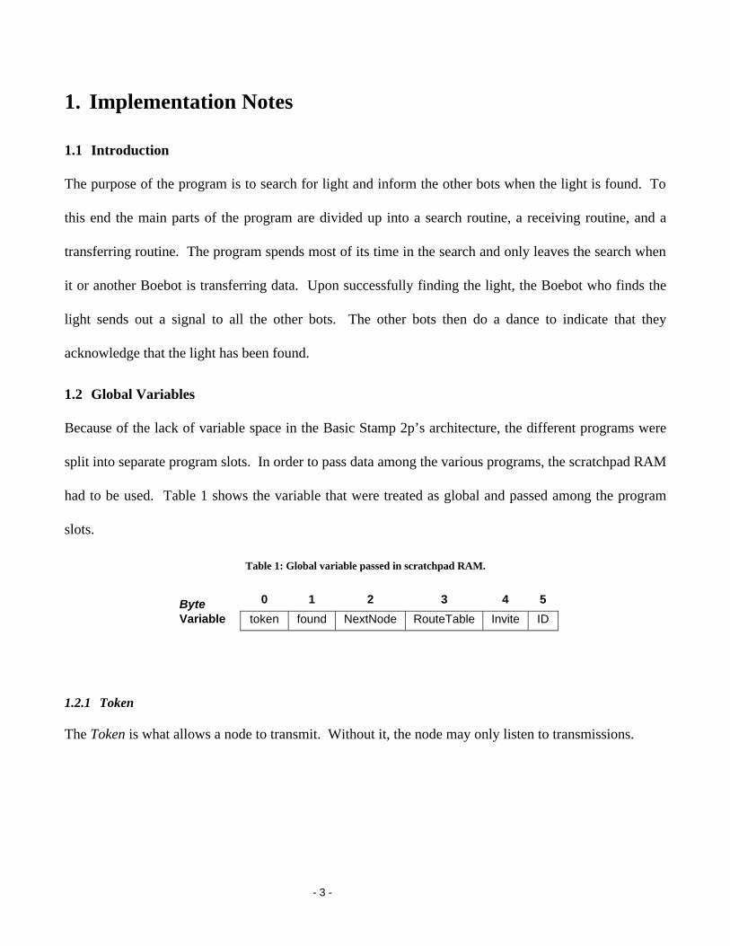
had to be used. Table 1 shows the variable that were treated as global and passed among the program
slots.
Table 1: Global variable passed in scratchpad RAM.
1.2.1 Token
The Token is what allows a node to transmit. Without it, the node may only listen to transmissions.
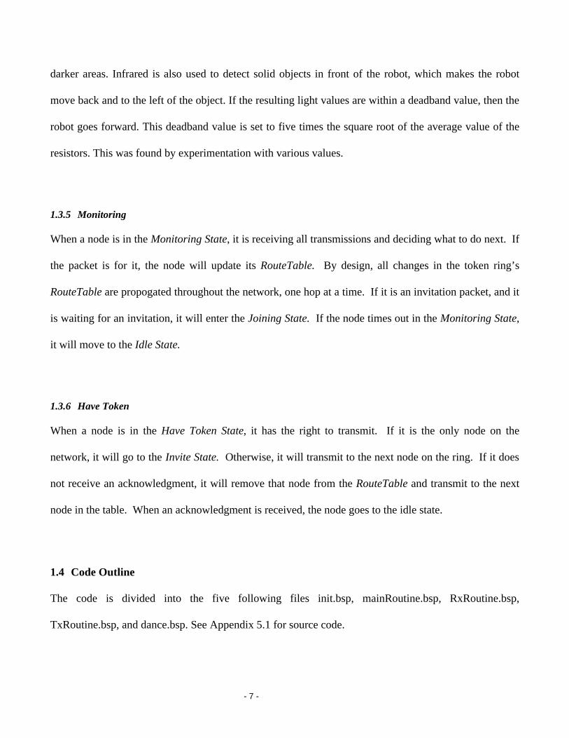
Byte 0 1 2 3 4 5
Variable token found NextNode RouteTable Invite ID
- 4 -
1.2.2 Found
The Found variable is responsible for saving the status of the light search. When a node finds the light,
a 1 is saved into Found. When it receives the token, the node may then transmit that it has found the
light.
1.2.3 NextNode
This is no longer used. NextNode is calculated directly from the RouteTable.
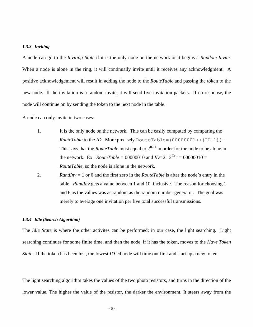
1.2.4 Route Table
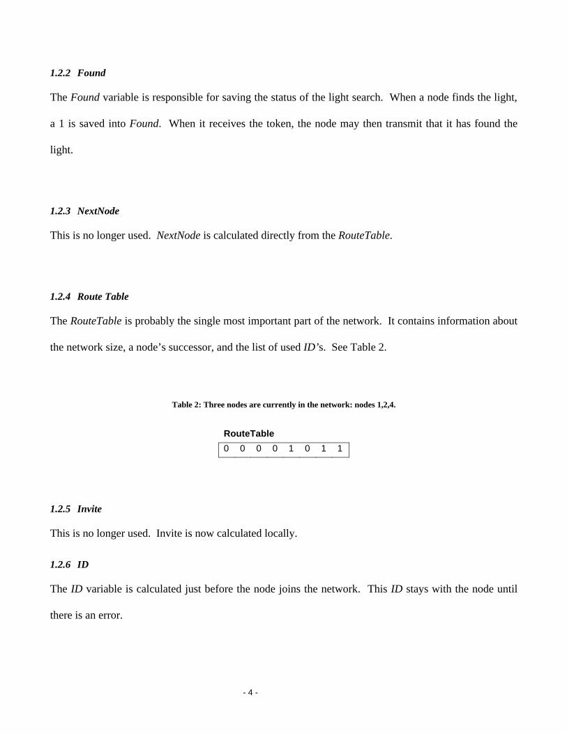
The RouteTable is probably the single most important part of the network. It contains information about
the network size, a node’s successor, and the list of used ID’s. See Table 2.
Table 2: Three nodes are currently in the network: nodes 1,2,4.
1.2.5 Invite
This is no longer used. Invite is now calculated locally.
1.2.6 ID
The ID variable is calculated just before the node joins the network. This ID stays with the node until
there is an error.
RouteTable
0 0 0 0 1 0 1 1
- 5 -
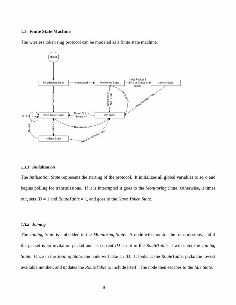
1.3 Finite State Machine
The wireless token ring protocol can be modeled as a finite state machine.
1.3.1 Initialization
The Intilization State represents the starting of the protocol. It initializes all global variables to zero and
begins polling for transmissions. If it is interrupted it goes to the Monitoring State. Otherwise, it times
out, sets ID = 1 and RouteTable = 1, and goes to the Have Token State.
1.3.2 Joining
The Joining State is embedded in the Monitoring State. A node will monitor the transmissions, and if
the packet is an invitation packet and its current ID is not in the RouteTable, it will enter the Joining
State. Once in the Joining State, the node will take an ID. It looks at the RouteTable, picks the lowest
available number, and updates the RouteTable to include itself. The node then escapes to the Idle State.
- 6 -
1.3.3 Inviting
A node can go to the Inviting State if it is the only node on the network or it begins a Random Invite.
When a node is alone in the ring, it will continually invite until it receives any acknowledgment. A
positive acknowledgement will result in adding the node to the RouteTable and passing the token to the
new node. If the invitation is a random invite, it will send five invitation packets. If no response, the
node will continue on by sending the token to the next node in the table.
A node can only invite in two cases:
1. It is the only node on the network. This can be easily computed by comparing the
RouteTable to the ID. More precisely RouteTable=(00000001<<(ID-1)).
This says that the RouteTable must equal to 2ID-1 in order for the node to be alone in
the network. Ex. RouteTable = 00000010 and ID=2. 2ID-1 = 00000010 =
RouteTable, so the node is alone in the network.
2. RandInv = 1 or 6 and the first zero in the RouteTable is after the node’s entry in the
table. RandInv gets a value between 1 and 10, inclusive. The reason for choosing 1
and 6 as the values was as random as the random number generator. The goal was
merely to average one invitation per five total successful transmissions.
1.3.4 Idle (Search Algorithm)
The Idle State is where the other activites can be performed: in our case, the light searching. Light
searching continues for some finite time, and then the node, if it has the token, moves to the Have Token
State. If the token has been lost, the lowest ID’ed node will time out first and start up a new token.
The light searching algorithm takes the values of the two photo resistors, and turns in the direction of the
lower value. The higher the value of the resistor, the darker the environment. It steers away from the
- 7 -
darker areas. Infrared is also used to detect solid objects in front of the robot, which makes the robot
move back and to the left of the object. If the resulting light values are within a deadband value, then the
robot goes forward. This deadband value is set to five times the square root of the average value of the
resistors. This was found by experimentation with various values.
1.3.5 Monitoring
When a node is in the Monitoring State, it is receiving all transmissions and deciding what to do next. If
the packet is for it, the node will update its RouteTable. By design, all changes in the token ring’s
RouteTable are propogated throughout the network, one hop at a time. If it is an invitation packet, and it
is waiting for an invitation, it will enter the Joining State. If the node times out in the Monitoring State,
it will move to the Idle State.
1.3.6 Have Token
When a node is in the Have Token State, it has the right to transmit. If it is the only node on the
network, it will go to the Invite State. Otherwise, it will transmit to the next node on the ring. If it does
not receive an acknowledgment, it will remove that node from the RouteTable and transmit to the next
node in the table. When an acknowledgment is received, the node goes to the idle state.
1.4 Code Outline
The code is divided into the five following files init.bsp, mainRoutine.bsp, RxRoutine.bsp,
TxRoutine.bsp, and dance.bsp. See Appendix 5.1 for source code.
- 8 -
1.4.1 init.bsp
In init.bsp everything is initialized to zero, polling is turned on for the receiving antenna, and a timeout
loop is begun. If the timeout loop is completed, ID is set to one and program control is transferred to
TxRoutine.bsp. The only way a timeout loop is not completed is if a signal is received from the antenna
in which case control is transferred to RxRoutine.bsp.
1.4.2 mainRoutine.bsp
All of the searching is contained in mainRoutine.bsp. Polling is turned back on at the beginning of the
routine in case it has been turned off in another routine. Inside main is a nested for loop. In the inner
loop the searching is done. If the value from both the photoresistors is less than a certain value than the
search is complete, found is set to one and control of the program is transferred to TxRoutine.bsp.
Otherwise the amount of distance to travel is decided by the average value of both the photoresistors and
the value of the left and right photoresistors is compared to determine if the boebot should travel left,
right, or forward. This is all done inside the inner loop. In the outer loop, we check to see if this boebot
has the token and if so we begin talking. If the boebot doesn’t have the token then the outer loop is used
as a timeout. Once it has been executed a certain number of times the boebot decides the node before it
has somehow been removed from the network. It than removes the previous node from the Route Table,
regenerates the token, and begins talking.
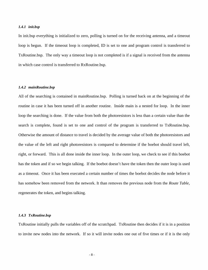
1.4.3 TxRoutine.bsp
TxRoutine initially pulls the variables off of the scratchpad. TxRoutine then decides if it is in a position
to invite new nodes into the network. If so it will invite nodes one out of five times or if it is the only

- 9 -
node in the network. If not it will determine the next node to pass the token to. It then calculates the crc
value and begins trying to transmit. It then transmits a synchronizer, the next node, the packet number,
the found bit, the invite bit, the route table, and the checksum. It will try this a set number of times and
if it does not receive a correct ack within those number of trys it will try the node after the node it is
trying to send to in the route table. If it is transmitting an invite, then it will change the routing table
when it receives an ack. Following all this, TxRoutine will then set the current node to not have the
token, save the route table to the scratch pad, and return to mainRoutine.bsp.
1.4.4 RxRoutine.bsp
RxRoutine pulls the node ID off of the scratchpad and initializes the other variables in the routine. It
then receives a synchronizer, the node being transmitted to, the packet count, the route table, and the
checksum. It then checks to see if there was an error in the checksum. If there was an error in the
checksum it assumes this is due to the presence of two tokens and sends out a message sending everyone
back to mainRoutine. If there is no error in the checksum, it checks the found bit and if it is set to one
then program control is transferred to dance.bsp. It then checks to see if it’s Id is zero or is not in the
route table and the invite bit has been sent and if so it assigns it the Id being invited. If the message
being transmitted to is for this node or this node is being invited into the network, it sends back an
acknowledgement and sets the token to one. It then returns to mainRoutine.
1.4.5 dance.bsp
This causes the boebot to move in circles continuously.
- 10 -
1.5 Hardware
The boebot comes from parallax and consists of several components. There is a chassis to which
everything attaches. There is a battery back that is mounted under the chassis. The circuit board is
called the board of education and is mounted on top of the chassis. The basic stamp attaches to the
board of education. Two servos and wheels are mounted along the chassis as well as a third wheel,
which is mounted on the back. The main peripherals we use with the boebot are two infrared LED’s and
two infrared sensors used for detecting objects near the boebot, two photo resistors used to detect if light
is near the boebot, and a radio frequency transmitter, a radio frequency receiver, and two antennas which
are used to communicate with the other boebots.
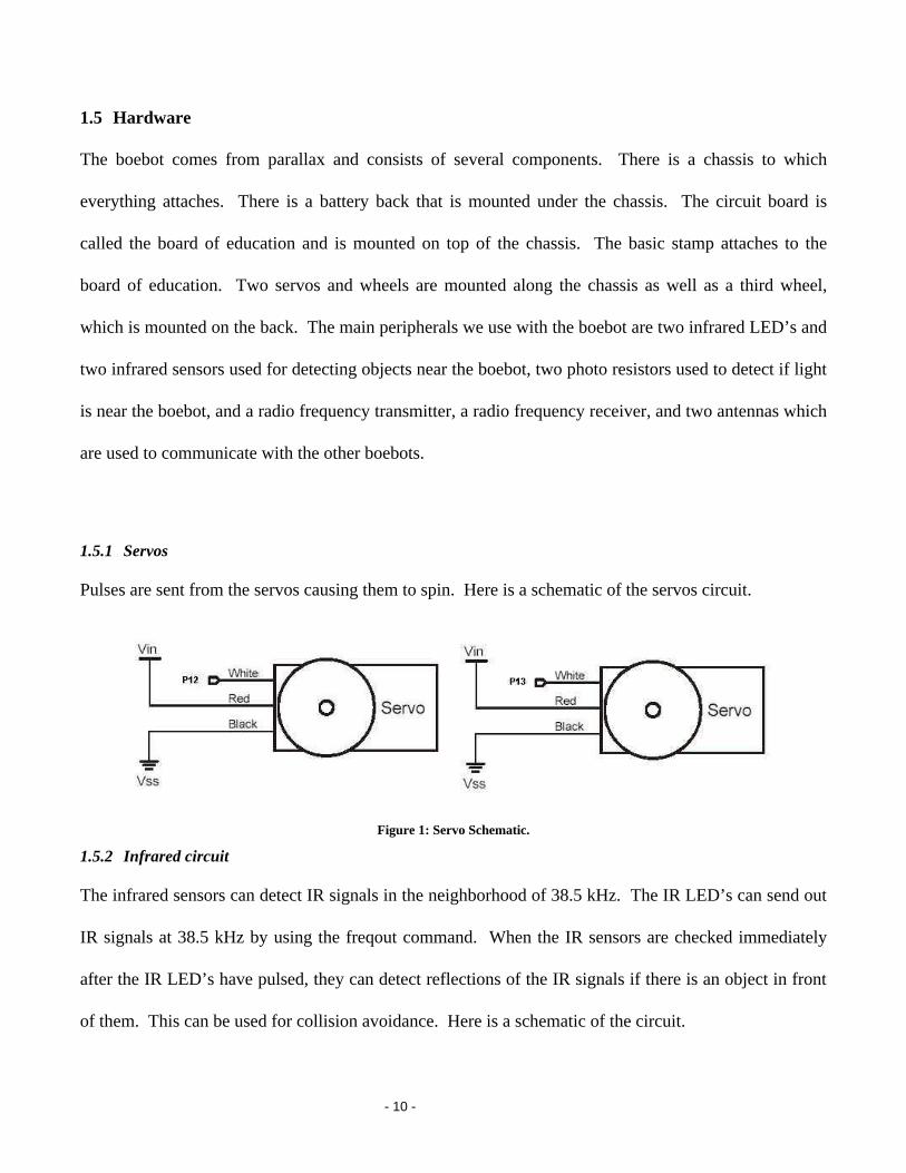
1.5.1 Servos
Pulses are sent from the servos causing them to spin. Here is a schematic of the servos circuit.
Figure 1: Servo Schematic.
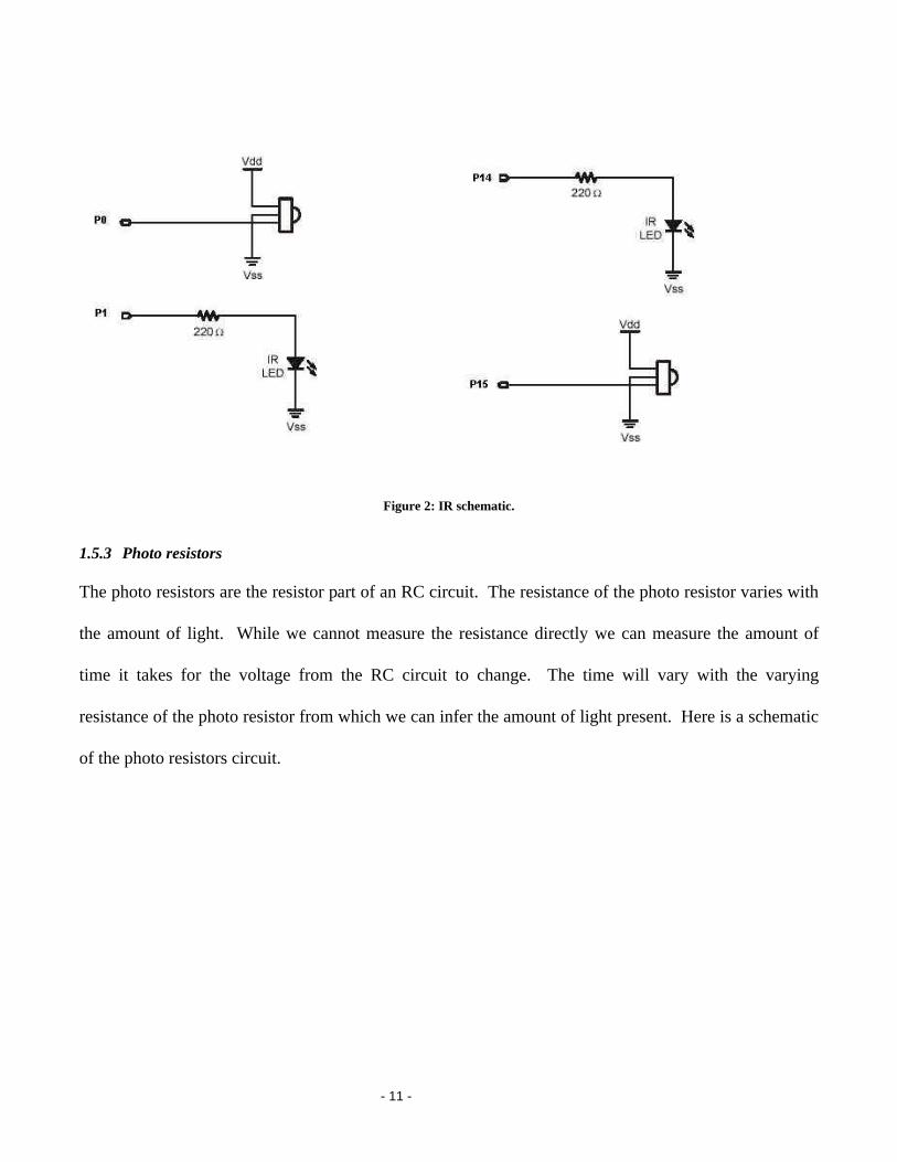
1.5.2 Infrared circuit
The infrared sensors can detect IR signals in the neighborhood of 38.5 kHz. The IR LED’s can send out
IR signals at 38.5 kHz by using the freqout command. When the IR sensors are checked immediately
after the IR LED’s have pulsed, they can detect reflections of the IR signals if there is an object in front
of them. This can be used for collision avoidance. Here is a schematic of the circuit.
- 11 -
Figure 2: IR schematic.
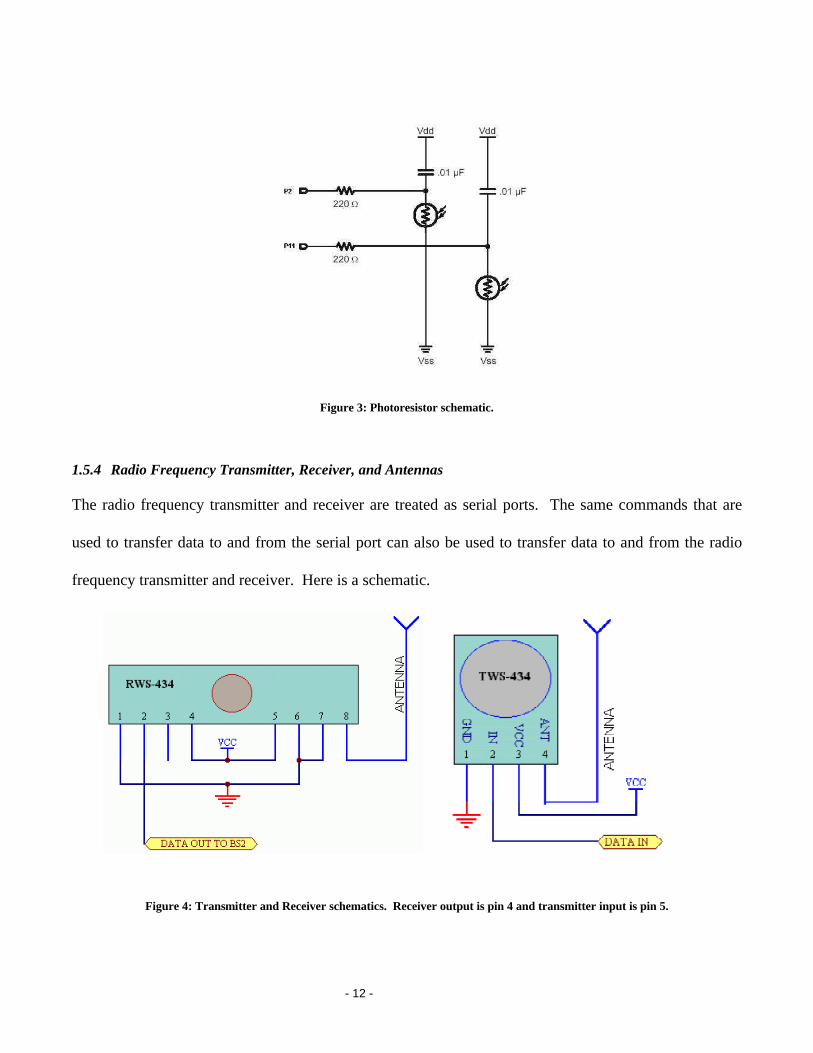
1.5.3 Photo resistors
The photo resistors are the resistor part of an RC circuit. The resistance of the photo resistor varies with
the amount of light. While we cannot measure the resistance directly we can measure the amount of
time it takes for the voltage from the RC circuit to change. The time will vary with the varying
resistance of the photo resistor from which we can infer the amount of light present. Here is a schematic
of the photo resistors circuit.
- 12 -
Figure 3: Photoresistor schematic.
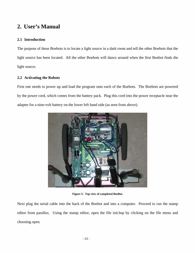
1.5.4 Radio Frequency Transmitter, Receiver, and Antennas
The radio frequency transmitter and receiver are treated as serial ports. The same commands that are
used to transfer data to and from the serial port can also be used to transfer data to and from the radio
frequency transmitter and receiver. Here is a schematic.
Figure 4: Transmitter and Receiver schematics. Receiver output is pin 4 and transmitter input is pin 5.
- 13 -
2. User’s Manual
2.1 Introduction
The purpose of these Boebots is to locate a light source in a dark room and tell the other Boebots that the
light source has been located. All the other Boebots will dance around when the first Boebot finds the
light source.
2.2 Activating the Robots
First one needs to power up and load the program onto each of the Boebots. The Boebots are powered
by the power cord, which comes from the battery pack. Plug this cord into the power receptacle near the
adapter for a nine-volt battery on the lower left hand side (as seen from above).
Figure 5: Top view of completed BoeBot.
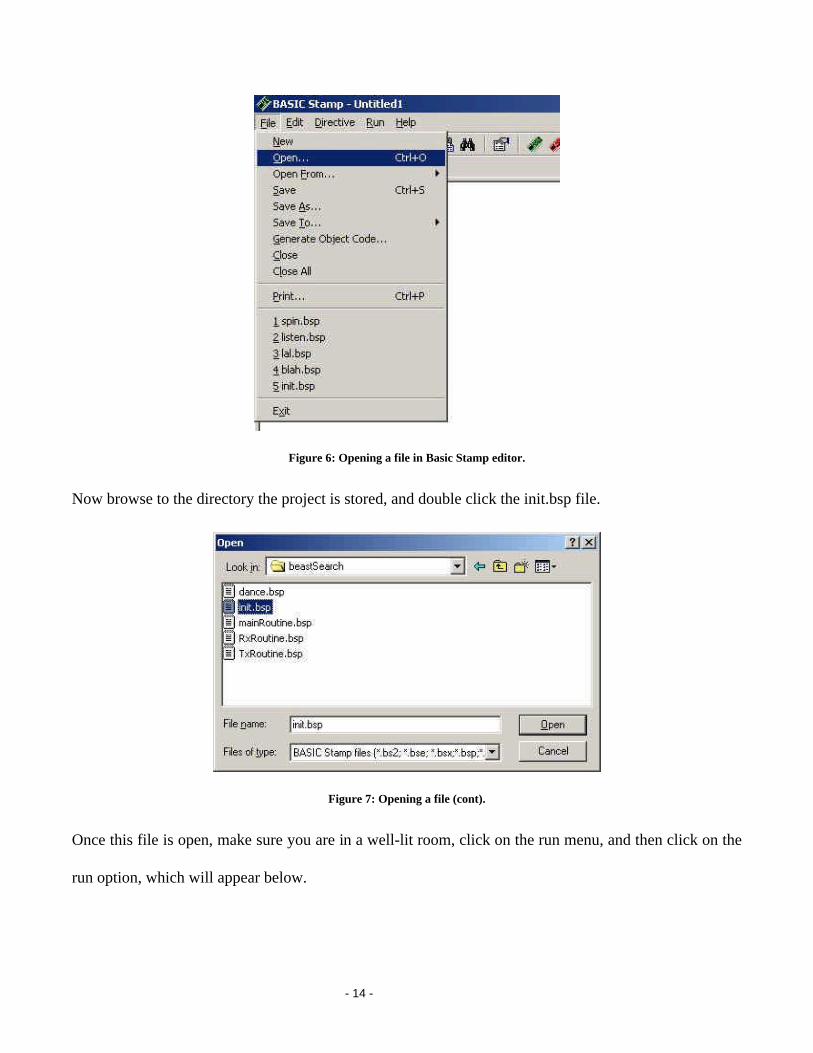
Next plug the serial cable into the back of the Boebot and into a computer. Proceed to run the stamp
editor from parallax. Using the stamp editor, open the file init.bsp by clicking on the file menu and
choosing open.
- 14 -
Figure 6: Opening a file in Basic Stamp editor.
Now browse to the directory the project is stored, and double click the init.bsp file.
Figure 7: Opening a file (cont).
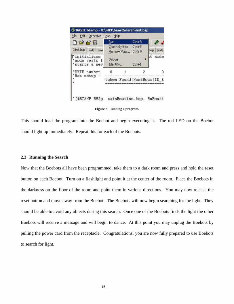
Once this file is open, make sure you are in a well-lit room, click on the run menu, and then click on the
run option, which will appear below.
- 15 -
Figure 8: Running a program.
This should load the program into the Boebot and begin executing it. The red LED on the Boebot
should light up immediately. Repeat this for each of the Boebots.
2.3 Running the Search
Now that the Boebots all have been programmed, take them to a dark room and press and hold the reset
button on each Boebot. Turn on a flashlight and point it at the center of the room. Place the Boebots in
the darkness on the floor of the room and point them in various directions. You may now release the
reset button and move away from the Boebot. The Boebots will now begin searching for the light. They
should be able to avoid any objects during this search. Once one of the Boebots finds the light the other
Boebots will receive a message and will begin to dance. At this point you may unplug the Boebots by
pulling the power card from the receptacle. Congratulations, you are now fully prepared to use Boebots
to search for light.
- 16 -
3. Course Debriefing
3.1 Group Management
There were several problems with our group management style. These led to some inefficiencies in our
group project.
One of the major problems our group had was a lack of communication. Some of goals and assignments
for various parts of the project were never communicated correctly, and this led to a loss of time and
effort for some people. Goals were redone several times, and some not done at all. Clear rules for
communicating would have led to increased productivity.
3.2 Safety and Ethical Concerns
There appears to be few safety concerns for the robot. The robot is too small, and has too little power to
serve as a danger to humans by either electrocution or contact.
The ethical concerns for the robot are few as well. The only conceivable one is that the frequency that
the robot transmits on (433 Mhz) could provide interference to some radio devices. This frequency is
used for amateur radio experiments, so the affect should be minimal.
3.3 Final Analysis of Solution
Our solution to this problem has one flaw, was that the program kept getting false positives for its
receive signals. This led us to analyze what was wrong with the receiver, and try to develop a solution.
- 17 -
3.4 Interference from the Servo Motors
One of the major problems in getting our searching and network integrated was electrical interference
received when we engaged our servos. The natural flow of our program was as follows:
1. Initiate network
2. Scan for light source
3. While scanning send and receive packets on the network
4. If the object is found, transmit this and end the program
The major problem is that to scan, the servomotors must be constantly turned on and off. We recognized
that this caused the receiver to transmit that it received a packet. As soon as the servomotor turned on,
the receiver would get a false signal, transferring the program control over to the receive subroutine.
Further investigation made us realize that these false signals were being caused by electrical and radio
frequency interference.
3.4.1 Electrical Interference
The electrical interference was obvious to see when we plugged in the Boe-Bot to the oscilloscope. See
Appendix 5.4 for testing code. When the difference between VCC and ground was measured, this was
the result:
- 18 -
Figure 9: Vdd during servo pulse.
This shows the voltage level of the power source. As it shows, when the servomotors are initialized, it
causes the voltage to take a sharp spike down, and then rise back up. After this, the receiver, which uses
this value to determine whether a signal is on the antennae. When the VCC dips, it then thinks it has
gotten a signal. When it does drop to the receive subroutine, the dip has passed, and there is not signal.
The behavior caused by this problem was as follows: the network would be established, but when the
search routine was initialized, the servos would be engaged. This caused the VCC dip, and the search
routine was interrupted. It tried to find a signal, failed, and then went back to the search routine. Thus the
process would repeat itself.
3.4.2 Solutions
We tried several different solutions for this problem. Each has some limited success in eliminating the
problem, but not enough to solve the underlying result of the VCC dip.
- 19 -
3.4.2.1 Grounding
Our preliminary thoughts were that this might be caused by the aluminum casing that the robot uses not
being grounded. A wire was connected from the casing to ground. This had no discernable affect.
3.4.2.2 Capacitors
The first solution was to smooth out the dip, by using capacitors. These would act as a short-term
battery, providing voltage through the dip, charging back up as the dip receded. First we tried using a
2200-microfarad capacitor. This provided no discernable difference in the voltage dip. After discussion
with the professor, it was decided that a large value capacitor did not provide a fast enough response to
the voltage dip.
It was then decided to use a string of multiple capacitors placed in parallel to simulate a larger capacitor,
with better response time. 470-microfarad capacitors were used to this. The results are as follows:
Figure 10: Vdd during servo pulse with 470uF capacitor.
- 20 -
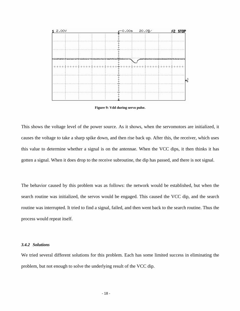
Figure 11: Vdd during servo pulse with 940uF capacitor.
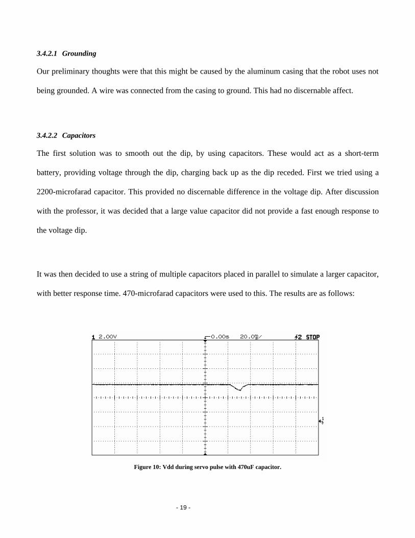
Figure 12: Vdd during servo pulse with 1410uF capacitor.
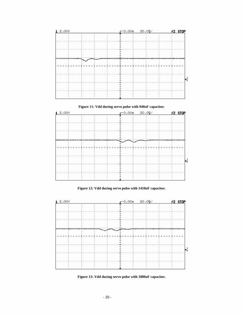
Figure 13: Vdd during servo pulse with 1880uF capacitor.
- 21 -
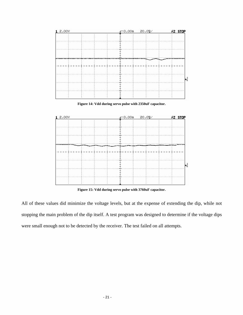
Figure 14: Vdd during servo pulse with 2350uF capacitor.
Figure 15: Vdd during servo pulse with 3760uF capacitor.
All of these values did minimize the voltage levels, but at the expense of extending the dip, while not
stopping the main problem of the dip itself. A test program was designed to determine if the voltage dips
were small enough not to be detected by the receiver. The test failed on all attempts.
- 22 -
3.4.2.3 Wait States
Another solution tried was to introduce wait states in the program’s flow. Instead of searching, and
polling while searching, it would separate the searching and the polling processes, and do each in turn.
This way the servo movements would not affect the receiver.
The problem with this solution is that this created windows in which the robots could not receive
packets. This was done by turning off polling for the result while the servo motors were activated. In
order to transmit the packet to the right receiver, the transmission would have to be repeated until the
robot was in a wait state. This might take 5 or more seconds. This lead to a great deal of missed packets,
and the network could not be established for long.
A modified solution with wait states was also tried. The poll mode option was turned off for 15ms after
each servo was run. 15 ms was used, as this was the approximate timeframe that the dip in VCC lasted.
This was meant to stop polling while the voltage was dropped, and start up when it returned to the right
level. This did not work, and only prolonged the point at which the receiver program reported the false
positive.
3.4.2.4 Non Polling Methods
We also thought that the act of polling might be the cause of the jump to the receive program. If the dip
in VCC only caused a transient shift in the receiver output, polling mode might be continuously
- 23 -
activated. If we used a large amount of if statements instead, then it might not pick up the transient
pulses. This did not work, as it did not have any noticeable affect on the dip.
3.4.3 RF interference
We made two small programs to test for RF interference. One called spin.bsp is used to spin the wheels
and wait for a little while, then spin the wheels again. It does this a total of ten times. The other
program is called listen.bsp. See Appendix 5.3 for source code. The listen program displays output
whenever it receives a signal from its antenna. We loaded the spin program onto one Boebot and the
listen program on another Boebot. We then placed the spin Boebot in various positions next to the listen
Boebot and watched the debug terminal to see how many times out of ten interference was caused in the
various positions. The two positions we chose were with the wheel and motor as close to the receiving
antenna as possible and with the wheel and motor next to the other Boebot. We repeated this test using
four different Boebots. We had each Boebot spin in both positions near each of the other Boebots with
the exception of the antenna-less Boebot, which only spun near the other Boebots but did not get to
listen since it did not have an antenna.
3.4.4 Solutions
In order to solve this problem, we designed several sets of insulation to stop the interference. Pink foam
was used to cover the receiver module. Silver insulation material, normally used to stop distortion in car
stereos, was used to wrap the servomotors. We then tested these insulations to find if they had an affect.

- 24 -
Here are our results:
The following table shows the Boebot with the uninsulated motors and an antenna listening to each of
the other Boebots in different positions.
Boebot Motor next to antenna Motor next to wheel
Pink insulated 10 0
Silver insulated 10 10
Uninsulated antenna X X
No antenna 0 0
The next table shows the Boebot with the silver chassis and insulated motors listening to each of the
other Boebots in different positions.
Boebot Motor next to antenna Motor next to wheel
Pink insulated 13 0
Silver insulated X X
Uninsulated antenna 5 0
No antenna 0 0
The next table shows the Boebot with the pink chassis and insulated motors listening to each of the other
Boebots in different positions.
Boebot Motor next to antenna Motor next to wheel
Pink insulated X X
Silver insulated 0 0
Uninsulated antenna 0 0
No antenna 0 0
- 25 -
This proves that there is RF interference since the listening Boebot is not spinning its wheels. It is
noteworthy that the Boebot with no antenna never produced any interference despite having no
insulation around its motors. This could indicate that the RF interference is not coming directly from the
motors themselves but from the transmit antenna of the Boebot with the wheels spinning. This could be
caused by an electric interference being sent to the transmitter when the wheels spin. It is also
noteworthy that the interference also seems to depend on the Boebot, which is receiving the interference.
This could be caused by the difference in sensitivity of the different antennas.
3.5 Conclusion
After exhausting all possible solutions to try and solve the servo problem, we decided to find a solution
that might not meet all of our objectives. We decided to keep the network as a prototype, but use the
search algorithm, along with a constant send on find. The robot would search for a while, then try to
detect a signal, and then search some more. If it found the light, it would transmit. If, during any of the
check times, the robot heard that someone had found the signal, it would enter the solved state.
This solved our problem of not being able to listen and move at the same time. The infinite transmit after
finding the solution allows the other robots to hear, whenever their respective listen times may be. It
does not, however, actually constitute a full network.
In conclusion, we have the following:
1. A working token based network that adds and removes nodes on an ad-hoc basis.
2. A working search routine that finds a point of light.
3. A non-working program that combines both
4. A program that finds a light and contacts other robots to tell them it found it.
- 26 -
4. Proposal
4.1 Purpose
We request funds and advising from professor and teaching assistants in order to develop a wireless
communication network for multi-robot teams. This network will allow the robots to function as a
sensor array, in order to function to a singular purpose: the finding of an object. Specifically, the robots
will communicate using radio frequency, or RF.
4.2 Background
Many projects that involve the use of robots involve more than one robot. In order to do a job, these
robots must work in parallel. The need for these robots to be able to communicate with each other has
led to the development of sensor networks.
A sensor is a device that produces a measurable response to a change in a physical condition. A sensor
network is a series of robots that contain sensors, and use the results from these sensors, and
communication with each other, to achieve some shared goal.
Many times sensor networks are distributed, meaning that all of the robots share duties. Many network
communication are on a client server setup, where one side gives directives to another. A distributed is
communication among equals. There is no one single error that can take down the system. Any single
unit can be disabled, but the network itself will continue to function.

- 27 -
Many applications benefit from such sensor networks. A network of robots can cover a large area, with
each robot going in a different direction. A faster solution can be found if more than one path is taken at
the same time, as with a sensor network. A groups of robots is also less prone to total failure, for if one
robot breaks down, the rest can still complete the objective. This makes sensor networks ideal for search
and retrieval missions, where their large coverage and constant communications mimic that of a human
search party.
There are also some problems with sensor networks. The largest hurdle is the requirement to be able to
constantly communicate with other, while mobile. This makes both line of site transmission systems,
like infrared, and wire based solutions unfeasible. This communication must also be set up on the fly, as
machines should able to enter and exit the communication process at any time.
The robots must also be cognizant of the other robots, and at least their relative position to it, in order to
be able to effectively share information about their surroundings. It is not enough to know that x robot
has found the objective. In order to use this information, it must know the location of the other robot.
Communication itself poses some challenges. If the robots are not in close contact with each other,
messages must be passed from one robot to another in order to route them to a specific robot. When we
add to this the fact that any one node can fail at any time, this leads to problems.
- 28 -
4.3 Problem Statement
Develop a wireless communication network for multi-robot teams. This network, preferably made
with radio frequency transceivers, plus the on board sensors of the robots themselves, will form a
sensor network, in order to locate a light source.
This will require the following:
1. A wireless communication system for multiple small robot micro controllers.
2. Schematic diagrams, parts list and instructions to assemble the system.
3. Project documentation, as described in the course syllabus.
4. A live demonstration of the robot in action.
The system is the main part of the project. It includes the robots, network protocols, and software
running the robot. This should all be in both written form and on the robots themselves.
The schematics and instructions should be clear enough so that anyone who wanted to recreate the
project could so easily. It is meant as a
The documentation should cover the process of building the robot, as well as evaluations on process and
management style. It should include a copy of this proposal, a user’s manual for operating the robots,
and comments on the success or failure of the project.
The demonstration will be done at the end of the project, and will show the robots in action. This should
be somewhat visual, as people outside the class will be observing it.

- 29 -
4.4 Design Constraints
The “wireless networks for multi-robot communications” project consists of requirements or goals that
either must be or should be followed. Constraints that must be strictly adhered to are listed under the
“must” category. Conditions that should be at least considered but are not deemed critical to the
application of the project are listed in the “should’s”.
4.4.1 This project must:
• Maneuver around obstacles. When an obstacle is encountered, the robot should take action to
avoid a dead stop. Solutions include but are not limited to infrared sensors, feeling whiskers,
object recognizing cameras, and ultrasonic radar.
• Be able to navigate independently of other robots. Each robot must have the ability to search
independently of the others. Also, it must have some sort of navigational protocol such as
random pattern, expanding circle, or straight lines until a barrier is encountered.
• Search for a user specified target such as a light. Each robot has to be able to search for and find
some predetermined target.
• Realize when it has found item or other robot. The robots must know when it is close enough to
the target or, if searching for a light, must determine when the brightness of the light is
satisfactory.
• Signal the other robots when the target is found. The discovering robot should send out a
broadcast that it discovered the target.
- 30 -
• Search for the robot that signals it has found the target. At that point it must supply some sort of
tracking mechanism for the other robots to find its current location.
• Not all communicate simultaneously. A protocol must be developed which will allow the robots
to listen prior to broadcasting. When the airwaves are clear, the robot may speak. If multiple
robot attempt to speak at exactly the same time, the robots can wait for a random amount of time
and attempt to rebroadcast.
• Not interfere or be interfered with in terms of RF communications. Surrounding wireless
networks, telephones, and other electronic devices must be considered when choosing the
frequency of the RF transceivers.
4.4.2 This project should:
• Allow the designers to easily modify the system behavior. Because of the complexity involved
with communicating among multiple nodes, the designer should not get bogged down in the
detail of how to write to and modify a chip.
• Allow the designers to easily interface new sensor and communication devices. Because the
obvious need for additional sensors (possibly transceivers, cameras, ultrasonic sensors, infrared,
whiskers), designers should have ample I/O connections and ease of interfacing.
• Use parts and tools readily available. Because of the numbers of robots needed, the other various
parts should be “off the shelf” parts if possible. Also, when choosing parts and robots, the tools
needed should be considered.
• Sense obstacles to avoid contact. This could possibly allow the robots to save power by
preventing them from sporadically changing directions upon contact with an obstacle.
- 31 -
• Consist of robots that will move reliably on the specified surface. The robot wheels should be
able to cope with the environment. Likely, a low pile carpet or tile floor will be used.
Consideration must be made for traction on tile.
• Allow for close enough distances so that the RF communications will not fail. If by chance the
RF communication link is extended beyond its usable distance, a search and rescue protocol
should be considered.
4.5 Metrics
The following metrics can be used in order to determine the validity of various solutions to the
networking robots problem.
4.6 Cost
The robots used in the project must be available for a minimum of cost. Sensor networks usually cover
tens or hundred of identical robots, each doing a small task. While our goal is not that lofty, in order to
develop a sensor network, we will have to have at least 3 or more robots, each with identical capabilities.
This will make minimizing the cost of each of the robots in the project a high priority of the project.
4.7 Stability
One of the greatest properties of a sensor network is how functions and data are distributed over the
network. Each robot only does a small part of the job, and combined, they do the task. Any sensor
network we design must have the ability to function whether or not all units are functional.
- 32 -
4.8 Size
In order to effectively design a sensor network project that can effectively exercise the sensor network’s
capabilities, one of two goals must be met. Either the area we test the sensor networks must be large
enough to require multiple robots to cover the area, or the robots must be small enough in respect to the
area of coverage. As making robots that will cover a large area will probably be cost prohibitive, the
robots that are in our project should be small enough to make a small area an effective test.
4.9 Adaptability
In order to do the various tasks of this project, whatever robot we use will have to be able to use a
variety of different inputs and outputs. More may be added, if we wish to expand the nature of the
program on a later date. One metric for any robot we use will be the ability to add on different sensors
and transmitters.
These items will allow the robot to both communicate with other robots, and search its surroundings,
both parts of the sensor network. The ability to add expand with additional inputs and outputs might also
be beneficial when debugging, where various events could cause the robot to light a light or ring a bell,
in order to show what was happening.
4.10 Work in this Field
Currently, there are several projects that have concentrated on sensor networks at various universities
and government agencies. Some of these have reached a prototype stage.
- 33 -
One of the most notable is the DARPA (Defense Advanced Research Projects Agency) project for
sensor networks. They envision “smart dust”: a sensor network made up of thousands of tiny robots,
each communicating with each other, and relaying information about the battlefield. The objective is to
make the robots small and light enough to float in the wind, scattering them, and landing on all surfaces.
Part of the DARPA project uses an open source operating system and database known as TinyOS and
TinyDB, respectively. This operating system is a runtime environment designed embedded systems
which require concurrency operations while constrained by minimal hardware resources. Many different
universities are using this as a starting point for their own projects.
One of the largest examples of using TinyOS was a Habitat monitoring project on Great Duck Island.
Thirty-two units, or “motes”, were deployed in order to monitor environmental conditions on the island.
Each could display temperature, humidity, and other environmental data.
Another example using TinyOS was to connect a building with a hundred motes in various places. These
monitored temperature, electric and light conditions. They collated this data for the user, showing what
parts of the house used electricity. This allowed for more informed energy consumption.
Sensor networks could also have many non-military applications. One idea is that of “pervasive
computing”. This is where thousands of small computers are inside you, and on your body, forming a
“nervous system” of sorts, that gathers and collates data. It would allow different computers to
“recognize” you based on the computers on your body.

- 34 -
One small step in this direction is RFID tags. Radio Frequency Identification tags are tiny microchips
that respond to radio frequencies with a transmission of their own. They are currently being tested in
many consumer goods, where the ability to identify individual goods quickly. Currently, each tag
transmits a 64 bit response to a radio signal, so they can have 18 thousand trillion different values.
One topic in computer science that predates the field of sensor networks is artificial life. Unlike artificial
intelligence, which tries to simulate a human mind, artificial life uses animal like behaviors in order to
achieve some goal. It uses small rule sets to produce complex behaviors. Each artificial life “creature”
only knows about its general area and makes decisions from what it can see. Several computer
simulations have had artificial life creatures simulate flocks of birds, and other pack animals. Some of
these are self evolving, changing their programs while running in order to produce better results.
Some less advanced sensor networks are used in factories. While traditionally networked, and with much
larger sized sensors, they still are effective. An example of this is the sensors in an automobile, that
record pressure and temperature values. These sensors are not mobile, but have some intelligence and
communication capabilities. They also report information back to a source.
4.11 Survey of possible robots
When considering what robot to purchase to start on our project, our team had several concerns. The top
priority was to find a robot that was somewhere in the two hundred to four hundred dollar range. Our
problem statement asks for a multi-robot team that is able to communicate with each other. We decided

- 35 -
on purchasing five robots with the possibility of adding an additional five later on. To stay within a
reasonable budget, we had to keep the price of each robot down.
We took the five most promising robots and critiqued each. The first robot we looked at was the
AmigoBot by ActiveMedia. The AmigoBot comes with the standard physical characteristics and
capabilities. It is 28 cm long (~11 inches) and 33 cm wide (~13 inches). It comes with 1 MB of flash
memory and an indoor range of 100m and an outdoor range of 250m. ActiveMedia also comes with
wireless accessories like the Wirefree Radio Modem. This option would be very useful in our case since
it is full duplex and uses the standard RS232 serial port. The downfall of the AmigoBot is that it uses its
own operating system, AmigoOS and the price is currently at $1795 each.
The second robot we took into consideration is the Khepera II by K-Team. K-team’s product came with
more memory than the AmigoBot but less Flash memory. K-team fell short of our expectations in
several areas. The sensing whiskers that ship with the robot are only 10cm long. The payload for the
robot is only 250 grams and the RF products might stretch that limitation. The Khepera model also
comes with software that is not made specifically for its product. It ships with National Instrument’s
LabView and MatLab. The unit price of the Khepera is not listed on the website and the only way to
figure out the price is to send off an email and wait for a reply back.
The next robot we looked into was the Trilobot by Arrick Electronics. This robot measured 12” x 12” x
12” and weighed 11 pounds. The Trilobot is the heaviest of the robots that we took into consideration. It
also requires the most voltage at 12V. The main disadvantage of the Trilobot is the price. Each product
is $1900.00 which is out of our price range.
- 36 -
The fourth robot on our list was the Hexapod by Lynxmotion. The Hexapod has the simplest and
straightforward design. We found the documentation to be very lacking though, and we were not ready
to gamble on whether the product would fit our needs or not. The Hexapod costs around $240. The
payload is also only 12 ounces, which again might not be enough to handle the additional RF Products.
The final robot that we surveyed was the Boebot by Parallax. It turned out to be the best candidate for
our project. It sells for around $230 a piece and comes with two helpful workbooks. Boebot comes with
whiskers and is constructed of an aluminum chassis. The Boebot has a smaller, yet strong frame so we
will not need a large testing area.
4.12 Design Validation
Each piece of the Boe-Bot can be tested individually and then tested again when everything is put
together. The servos, whiskers, photoresisters, and IR subsystem can each be tested individually as
outlined in the Boe-Bot manual. Then we must test the servos, whiskers, photoresisters, and IR
subsystem when all of them are working in unison. We need to implement and test a random search for
light using a single Boe-Bot. Then we need to implement and test patterned searches for the light using
a single Boe-Bot.
At the same time we can begin implementing and testing RF communication between two Boe-Bots.
Following successful communication between two Boe-Bots, we can develop, implement, and test a
communication protocol for an arbitrary number of Boe-Bots.
- 37 -
Upon successful implementation of a multi-Boe-Bot communication protocol and the individual Boe-
Bot random and patter searches, we can combine the searches with the communication protocol to
implement multi-Boe-Bot random and pattern searches for light. This step will require an iterative series
of test as we determine which search is best, how close the Boe-Bots should get to each other before
changing direction, and try to develop a method for each Boe-Bot to determine where the other Boe-Bots
are at all times. We will then need to test this with various obstacles blocking the search for the light
and with removal and addition of Boe-Bots to the search.
4.13 Societal, Environment, and Safety Analysis
Use of small autonomous robots for different tasks stands to have great benefits for society. They will
allow for jobs to be done cheaply by many small robots instead of expensively by large ones. Sensor
networks will allow people the ability to monitor events over very large areas with ease.
There are some problems with sensor network technology. If sensor networks are so ubiquitous, it might
be very easy to have millions of them, monitoring everything in a given area. The privacy concerns are
significant. This should be minimal for our project, as it does not concern robots in any large number.
Neither do the Boe-Bots have any capacity for surveillance work.
The use of large amounts of Boe-Bots would have some environmental concerns. As the Boe-Bots are
small, and easily damaged, many might have to be thrown away. The electronic chips and plastic that are
used to create a Boe-Bot are not biodegradable and the chips may contain hazardous materials.
- 38 -
Using five Boe-Bots may also cause other problems. Each robot requires four double A batteries.
Depending on how often these need changing, they might generate a large amount of somewhat
hazardous waste. Batteries become corrosive with time, so proper disposal of the batteries is necessary.
Using a Boe-Bot may have some advantages environmentally though. Five Boe-Bots may be able to do
the job of one larger robot. This robot could use more resources than the smaller robots, and must be
replaced if broken. Each of them also probably uses much less power than the larger robot, and probably
costs less.
Safety concerns are minimal for the BoeBot. They are quite small, and there is little chance that any
collision with a human or any other object will result in any damage. The amount of power they
consume is quite small, so any exposure to an open circuit will result in only a small electric charge. The
only real hazard the robot poses is the threat of when it breaks. If the robot is broken into small pieces,
there is a chance that they could be sharp and cut something or someone.
While the BoeBot poses little threat to outside elements, these elements may pose threats to it. It might
be easily stepped on, causing large amounts of damage to the robot. It could also be exposed to the
water, or other elements, also causing damage to it.
- 39 -
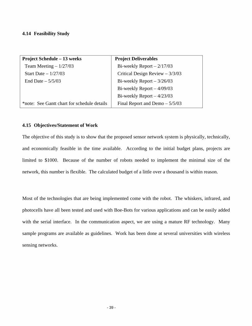
4.14 Feasibility Study
Project Schedule – 13 weeks Team Meeting – 1/27/03 Start Date – 1/27/03 End Date – 5/5/03 *note: See Gantt chart for schedule details
Project Deliverables Bi-weekly Report – 2/17/03 Critical Design Review – 3/3/03 Bi-weekly Report – 3/26/03 Bi-weekly Report – 4/09/03 Bi-weekly Report – 4/23/03 Final Report and Demo – 5/5/03
4.15 Objectives/Statement of Work
The objective of this study is to show that the proposed sensor network system is physically, technically,
and economically feasible in the time available. According to the initial budget plans, projects are
limited to $1000. Because of the number of robots needed to implement the minimal size of the
network, this number is flexible. The calculated budget of a little over a thousand is within reason.
Most of the technologies that are being implemented come with the robot. The whiskers, infrared, and
photocells have all been tested and used with Boe-Bots for various applications and can be easily added
with the serial interface. In the communication aspect, we are using a mature RF technology. Many
sample programs are available as guidelines. Work has been done at several universities with wireless
sensing networks.
- 40 -
As seen in the Gant chart , we should have enough time to complete all design objectives. We should
also have some room for unexpected problems if any occur. The mistakes may come from trying to
integrate all of the different parts of the robot into a whole, but there should be enough time to do this.
4.16 Management
Team organization will be loosely based. Decisions will be made by group consensus, and then carried
out. Tasks will be delegated based on who can do the job effectively and quickly.
If there are design disagreements, we will either ask the profession for advising, or see if some form of
compromise can be made.
The project will be managed under a cycle type of qualifications. Each unit will be planned, designed,
and tested. Then, all units will be integrated, then the whole will be tested.
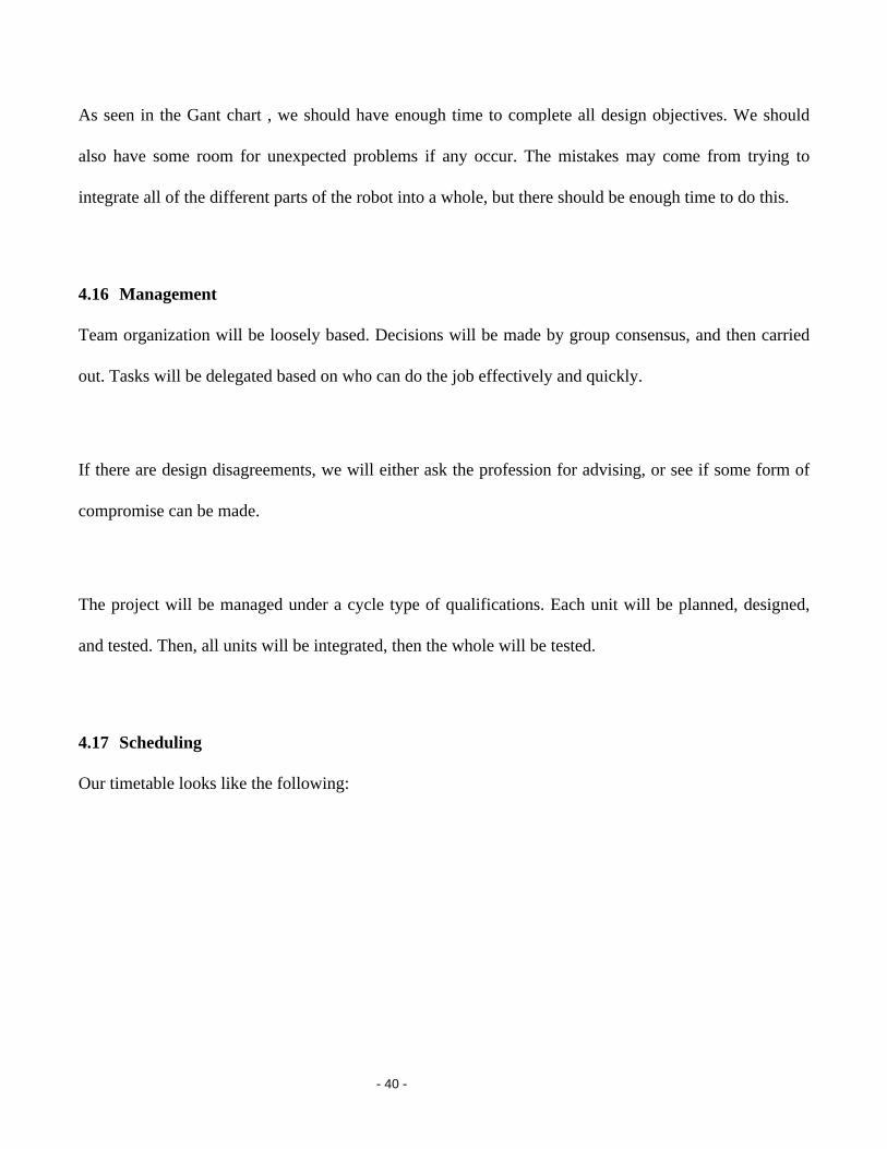
4.17 Scheduling
Our timetable looks like the following:
- 41 -
Timeline
3 4 5 6 7 8 9 10 11 12 13 14 15 16
Presentation
Testing
Integrate
RF Software
Integrate
Searching Software
Initial movement of Bots
Build Bots
Parts List
Proposal
Week
Figure 16: Gantt Chart.
As shown, there is plenty of time for both design and testing of different components in the system, as
well as testing of these various components. Each unit of the project has been checked for dependencies
with all of the others.
Most of our work units will take two weeks. There is some leeway in the testing, as it is an on going,
continuous process. It will be done as units are completed. The presentation itself will be done after the
software and hardware is finished.
There are several dependencies for various subunits of the process. The robots must be built before any
of the other work can be done. The IR, RF, whiskers, and photocells are all independent of each other. In
order to search for a light, the photocells, whiskers, and IR must be completed. Robots talking with each
other require the RF to be completed. Finally, both are required for the fully functional robot to be built.
- 42 -
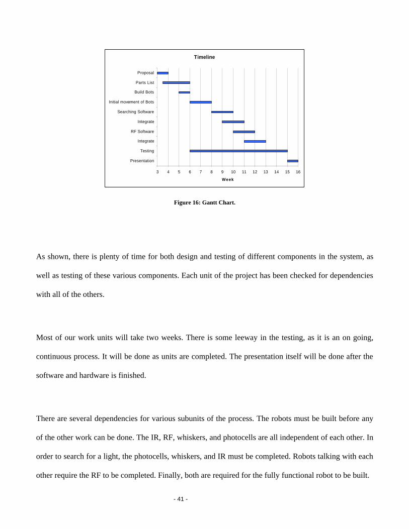
4.18 Budget
Our Budget will look like the following:
Table 3: Expected Budget.
Sensor Networks Budget
Product Quantity Price
Boe-Bot Full Kit 5 1145
w/shipping 1157.28
Transmitter (TWS-434) 5 38.25
Receiver (RWS-434) 5 38.25
433 MHz Antenna 5 45
w/shipping 130.84
Alkaline Batteries (AA) 100
Total Cost 1388.12
The total cost goes come to slightly above 13 hundred dollars, a reasonable amount for our project.

- 43 -
Proposal Choose parts
Order parts
Connect servos to robots
Build robots
Get robots moving
Connect whiskers
Write and implement obstacle avoidance software
Connect photocells
Write and implement light sensing software
Connect RF transmitter and
receiver
Write and implement RF
software
Write and implement networking protocol
Connect IR
Write and implement IR
Write and implement object searching
Write and implement object tracking
Create team
(Optional – if time permits) Search and
rescue lost robots
- 44 -
5. Appendix
5.1 Code for Token ring network with searching integrated.
5.1.1 Init.bsp
'initializes new node or timed-out node 'node waits for any Rx, if none, 'starts a new token 'BYTE number 0 1 2 3 4 5 'Ram setup - --------------------------------------- ' |token|Found|NextNode|ID_taken|Invite|ID| ' --------------------------------------- '{$STAMP BS2p, mainRoutine.bsp, RxRoutine.bsp, TxRoutine.bsp, Dance.bsp} '----------init---------- 'run slot 2, Rx token VAR BIT time VAR WORD ID VAR BYTE token = 0 time = 0 ID = 0 '------------------- Initialize all global variables ----------------------- PUT 5, ID 'initialize ID to 0 and store in ram PUT 4, 0 PUT 3, 0 PUT 2, 0 PUT 1, 0 PUT 0, 0 pollin 4,1 'poll for Rx pollmode 3 'polled-run only pollrun 2 TIMeOUT con 400 'may need something better '---------main----------- start: if time > TIMEOUT then start_token 'listen, if nothing, start new token DEBUG "I am counting ", DEC time, CR time = time + 1 goto start start_token: DEBUG "Start up token", CR 'token = 1 'give node the right to Tx ID = 1 'give node ID = 1 'put 0, token 'save token and ID in RAM put 5, ID 'before calling new program put 3, %00000001 'initialize route table to empty run 3 'run transmit program
- 45 -
5.1.2 main.bsp
'BYTE number 0 1 2 3 4 5 'Ram setup - --------------------------------------- ' |token|Found|NextNode|ID_taken|Invite|ID| ' --------------------------------------- '{$STAMP BS2p} 'run slot 1 token VAR BIT PrevNode VAR BYTE ID VAR BYTE x VAR WORD y VAR WORD z VAR WORD ID_taken VAR BYTE IDShift VAR BYTE pulse_count var byte right_photo var word left_photo var word distance_mult var nib avg_value var word deadband var word left_IR var bit right_IR var bit output 15 output 1 'PUT 2, NextNode 'PUT 1, ID GET 0, token GET 5, ID debug ? token pollin 4,1 'poll for Rx pollmode 3 'polled-run only pollrun 2 '--------------------main--------------- main: 'FIXME if ID = 0, then want to do a random backoff for x = 1 to (ID+4) 'this is like a timeout that is based on ID 'The lower ID should always start the token 'could be some timing issues '8000 is about max b/c 8000*8=64000 ~ 2^16 'may want smaller than 8000 for y = 1 to 10 '********************************* ' SEARCHING ALGORITHMS '********************************* 'SearchMain: Debug "searching", CR 'Scan the values goto scan decision: 'Following commands used to experiment with values 'If we find the right values, then stop if (left_photo < 50) and (right_photo < 50) then ende 'Find an average values for use with the multiples avg_value = (left_photo + right_photo) / 2 DEBUG "AVG ", DEC avg_value, CR deadband = 5 * SQR avg_value 'Determine our deadband and distance values for the computer
- 46 -
if (avg_value > 1000) then high_multiple if (avg_value > 500) then mid_multiple if (avg_value > 300) then low_multiple 'Determine if something is in front of the bot, avoid 'it and turn and follow light move: if left_IR = 0 and right_IR = 0 then uturn if left_IR = 0 then right_turn if right_IR = 0 then left_turn PulseNext: DEBUG "D", DEC deadband, CR, CR Debug "Maybe" if abs(right_photo-left_photo) < deadband then pulse_forward if left_photo > right_photo then pulse_right if right_photo > left_photo then pulse_left if right_photo = left_photo then pulse_forward BackFromPulse: NEXT '********************************* if token = 1 then talk 'after searching for some time, then talk if have token debug CR,"twiddling thumbs", CR next '------------------- if timeout, remove previous node from list and fire up a token ------------ GET 5, ID GET 3, ID_taken IDShift = %1 GetPrevNode: if ID_taken=(IDShift<<(ID-1)) then ReturnToCall 'means that node is alone on network if ID=1 then Wrap for x = (ID-2) to 0 if (ID_taken>>x) & %1 = 1 then SetPrev Next Wrap: for x = 7 to ID if (ID_taken>>x) & %1 = 1 then SetPrev Next Debug CR, "there was an error getting the next ID (main)", CR SetPrev: PrevNode=x+1 ID_taken = ID_taken & ~(DCD (PrevNode-1)) put 3, ID_taken ReturnToCall: RUN 3 '----------------------------------------------------------------------------------------------- talk: RUN 3 ende: debug "ende", CR put 1,1 high 8 RUN 3 scan: 'scan for IR freqout 1, 1, 12000 right_IR = in0 debug "RIR", DEC right_IR, CR 'scan for light high 2 pause 3 rctime 2,1,right_photo right_photo = abs(right_photo) if right_photo <> 0 then regularright right_photo = 32000
- 47 -
regularright: debug "R", DEC right_photo, CR freqout 15, 1, 12000 left_IR = in14 debug "LIR", DEC left_IR, CR high 11 pause 3 rctime 11,1,left_photo left_photo = abs(left_photo) if left_photo <> 0 then regularleft left_photo = 32000 regularleft: debug "L", DEC left_photo, CR, CR goto decision left_turn: for pulse_count = 1 to 40 pulsout 12, 750 pulsout 13, 750 pause 20 next goto PulseNext right_turn: for pulse_count = 1 to 40 pulsout 12, 2500 pulsout 13, 2500 pause 20 next goto PulseNext pulse_left: 'pollmode 0 for pulse_count = 1 to (distance_mult / 2) pulsout 12, 750 pulsout 13, 750 pause 20 next goto BackFromPulse pulse_right: for pulse_count = 1 to (distance_mult / 2) pulsout 12, 2500 pulsout 13, 2500 pause 20 next goto BackFromPulse pulse_forward: for pulse_count = 1 to (distance_mult) debug "Forward HOOOOO", CR pulsout 12, 750 pulsout 13, 2500 pause 20 next goto BackFromPulse uturn: for pulse_count = 1 to 80 pulsout 12, 2500 pulsout 13, 2500 pause 20 next goto PulseNext high_multiple:
- 48 -
distance_mult = 40 'deadband = 9000 goto move mid_multiple: distance_mult = 20 'deadband = 5000 goto move low_multiple: distance_mult = 4 'deadband = 100 goto move
- 49 -
5.1.3 RxRoutine.bsp
'BYTE number 0 1 2 3 4 5 'Ram setup - --------------------------------------- ' |token|Found|NextNode|ID_taken|Invite|ID| ' --------------------------------------- '{$STAMP BS2p} pollmode 0 '---Set up Variables--- PacketCount VAR BYTE 'Packet Number and Data Value Count PrevPacket VAR NIB 'Previous Packet Number CRC VAR WORD 'Calculate CRC value CRCL VAR CRC.LOWBYTE 'Low byte of calculated CRC value CRCH VAR CRC.HIGHBYTE 'High byte of calculated CRC value RcvdCRC VAR WORD 'Received CRC value RcvdCRCL VAR RcvdCRC.LOWBYTE 'Low byte of received CRC value RcvdCRCH VAR RcvdCRC.HIGHBYTE 'High byte of received CRC value CValue VAR BYTE 'Temporary holder of value for CRC calculation RcvdNextNode VAR BYTE ID VAR BYTE Found VAR BIT Invite VAR BIT ID_taken VAR BYTE 'list of ID's in use. Ex. 11010010 = ID 2,5,7,8. 'Supports 8 nodes. See figure at bottom of page. ErrorCount VAR NIB 'Number of Non-receives CASE VAR NIB '---Set up Constants--- Tx CON 5 'Transmit I/O pin number Rx CON 4 'Receive I/O pin number N9600 CON 18447 'Baud mode value for 9600 baud, 8,N,1 Initialize: LOW Tx 'Initialize transceiver interface DEBUG CR,"Action Packet# Invite Checksum Next Routes Status" DEBUG CR,"-------- ------- ------ -------- ---- ---------- ------" GET 5,ID ErrorCount = 0 '---------------------------------- Receiver Subroutines ----------------------------------- ReceiverMain: GOSUB Receive 'Call the receive routine IF PacketCount = 0 THEN DoOtherStuff DoOtherStuff: 'Here is where you should do other desired tasks GOTO ReceiverMain '---------------------------------- Packet Receive Subroutines --------------------------------- Receive: if ErrorCount>4 then NORECEXIT 'If too many errors, then quit trying DEBUG CR,"Receive " 'Look for incoming data packet SERIN Rx,N9600,600,NoReceive,[WAIT("ABC"),RcvdNextNode,PacketCount,ID_Taken,RcvdCRCL,RcvdCRCH] DEBUG DEC2 PacketCount>>4,REP " "\8,DEC2 PacketCount&%1, REP " "\6, DEC1 Invite DEBUG DEC5 RcvdCRC,REP " "\6,DEC2 RcvdNextNode," ", BIN8 ID_taken, CR '-------------------------------------- Calculate CRC ------------------------------------------ CRC = 0 CValue = PacketCount>>4 'Data was received, so well prime the checksum if CValue = 0 THEN Error 'If Packet# = 0, error (illegal value) GOSUB CalcCRC
- 50 -
Found = PacketCount>>1 & %1 CValue = Found 'Get Found Variable / calc CRC GOSUB CalcCRC Invite = PacketCount&%1 CValue = Invite 'Get Invite Variable / calc CRC GOSUB CalcCRC CValue = RcvdNextNode 'Calc CRC with RcvdNextNode GOSUB CalcCRC CValue = ID_taken 'Calc CRC with ID_taken GOSUB CalcCRC IF CRC <> RcvdCRC THEN Error 'Is calculated Checksum same as Received Checksum? IF Found=1 then dance Debug CR, "BIGIF=", BIN8 (ID_taken & (DCD (ID-1))), CR Debug "DCDID=", BIN8 DCD(ID-1), CR Debug ? Found IF (ID_taken & DCD (ID-1) = 0) OR ID=0 then NoSetFlag SetFlag: Invite=0 NoSetFlag: '--------------------------- If invited to join ring ------------------------------------------- if Invite=1 and (ID=0 OR (ID_taken & DCD (ID-1) = 0)) then GETID 'Invitation packet so find an unused ID if you don't have hone ReturnGETID: DEBUG ? ID PUT 5, ID 'Set the ID 'PUT 4, 1 'Set the invitation flag PUT 3, ID_taken 'PUT ID_taken to RAM for future additions 'GOTO Accept 'Send ID with Ack message. Accepts invitation 'FIXME: Change for invitation. If invite, then RcvdNextNode doesn't matter. 'timing issues. if RcvdNextNode=ID OR Invite=1 then SendAck 'Packet was not for me and it was 'not an invite packet, debug "Message not for me so I will exit", CR pause 2 GOTO EXIT 'if not joining or token not for you, 'then pause and exit. 'so ignore it SendAck: DEBUG "Tx Ack",REP " "\27,DEC5 CRC,REP " "\25,"OK" PAUSE 1 'Give sender time to get ready to receive 'acknowledgement 'SEROUT Tx\TxFlow,N9600,[CRCL,CRCH] 'Yes! Send positive acknowledgement (the checksum) SEROUT Tx,N9600,["XYZ","ABC",Invite, CRCL,CRCH] 'Send invite flag piggy backed on ack IF PacketCount>>4 = PrevPacket THEN Duplicate 'If duplicate packet, we'll ignore it PrevPacket = PacketCount>>4 'Record previous packet number PUT 0, 1 'I now have the token GOTO EXIT NoReceive: DEBUG REP " "\45,"NO RECEIVE" PacketCount = 0 'Clear PacketCount to indicate no data received ErrorCount = ErrorCount+1 RETURN 'FIXME 'If error, need to escape to prog 1 'may want to allow this to happen once and then recheck Error: DEBUG "Tx NAck",REP " "\26,DEC5 ~CRC,REP " "\22,"ERROR", CR 'SEROUT Tx\TxFlow,N9600,[~CRCL,~CRCH] 'Error receiving, send negative acknowledgement '(Not Checksum) Invite = 0 SEROUT Tx,N9600,["XYZ","ABC",Invite,~CRCL,~CRCH] put 0, 0 'Everyone relinquishes token RUN 1 'CRC error: assume multiple tokens '(interference) so reinit token Duplicate:
- 51 -
DEBUG CR,"No Op", REP " "\28,DEC5 CRC,REP " "\25,"DUPLICATE" PacketCount = 0 put 0, 1 GOTO EXIT 'Clear PacketCount to indicate no new data received RETURN '-------------------------------- CRC Checksum Calculation Routine ---------------------------- CalcCRC: CValue= CRCH^CValue>>4^(CRCH^CValue) CRC = CValue^(CValue<<5)^(CValue<<12)^(CRC << 8) RETURN NORECEXIT: put 0,0 GOTO EXIT 'FIXME 'do we need to store any data before leaving? EXIT: RUN 1 '------------------------------------Get ID subroutine ----------------------------------------- 'ID_taken format example ' 8 7 6 5 4 3 2 1 '-------------------------------- '| 0 | 0 | 0 | 0 | 1 | 0 | 1 | 1| '-------------------------------- 'This means that the ID's 1,2,4 are taken. 3,5,6,7,8 are free to take. '1 starts as the LSB to prevent extra shifting calculations since you want 'to use the lowest numbers first CASE = 15 'Set to 15 for default value GETID: Debug CR, "Getting ID", CR LOOKDOWN 0,[ID_taken&%1,ID_taken>>1&%1,ID_taken>>2&%1,ID_taken>>3&%1,ID_taken>>4&%1,ID_taken>>5&%1,ID_taken>>6&%1,ID_taken>>7&%1],CASE BRANCH CASE,[ID1,ID2,ID3,ID4,ID5,ID6,ID7,ID8] ID1: ID = 1 ID_taken = ID_taken+1 GOTO ReturnGETID ID2: ID = 2 ID_taken = ID_taken+2 GOTO ReturnGETID ID3: ID = 3 ID_taken = ID_taken+4 GOTO ReturnGETID ID4: ID = 4 ID_taken = ID_taken+8 GOTO ReturnGETID ID5: ID = 5 ID_taken = ID_taken+16 GOTO ReturnGETID ID6: ID = 6 ID_taken = ID_taken+32 GOTO ReturnGETID ID7: ID = 7 ID_taken = ID_taken+64 GOTO ReturnGETID ID8: ID = 8 ID_taken = ID_taken+128 GOTO ReturnGETID dance: debug CR, "Going to dance", CR RUN 4
- 52 -
5.1.4 TxRoutine.bsp
'BYTE number 0 1 2 3 4 5 'Ram setup - --------------------------------------- ' |token|Found|NextNode|ID_taken|Invite|ID| ' --------------------------------------- '{$STAMP BS2p} pollmode 0 '---Set up Variables--- Packet VAR NIB 'Packet Number ErrNoAck VAR NIB 'Number of No Acknowledgement Errors CRC VAR WORD 'Calculate CRC value CRCL VAR CRC.LOWBYTE 'Low byte of calculated CRC value CRCH VAR CRC.HIGHBYTE 'High byte of calculated CRC value RcvdCRC VAR WORD 'Received CRC value RcvdCRCL VAR RcvdCRC.LOWBYTE 'Low byte of received CRC value RcvdCRCH VAR RcvdCRC.HIGHBYTE 'High byte of received CRC value CValue VAR BYTE 'Temporary holder of value for CRC calculation NextNode VAR BYTE 'Next node in route to pass the token to Found VAR NIB 'Found bit (Nib for packing purposes), 1=Found Light, '0=Not found light Invite VAR BIT 'Invitation bit, 1=Invite, 0=Normal Operation ID_taken VAR BYTE 'list of ID's in use. Ex. 11010010 = ID 2,5,7,8. Supports up to 8 nodes InviteRec VAR BIT NumGen VAR word 'Random number 16bits RandInv VAR NIB 'Random num between 1&whatever is chosen 'for invitation purposes ID VAR BYTE NextNodeID VAR BYTE IDShift VAR BYTE counter VAR NIB x VAR NIB '---Set up Constants--- Tx CON 5 'Transmit I/O pin number Rx CON 4 'Receive I/O pin number N9600 CON 18447 'Baud Initialize: LOW Tx 'Initialize transceiver interface DEBUG CR,"Action Packet# Invite Checksum Next Routes Status" DEBUG CR,"-------- ------- ------ -------- ---- ---------- ------" IDShift = %1 'GET 2,NextNode GET 1,Found GET 3,ID_taken GET 5,ID Invite = 1 NextNodeID = 0 '************************Invite************************* 'Decide whether the node should send out an invitation if ID_taken & %1 = 0 then findLast1 for counter = 1 to 7 if (ID_taken >> counter) & %1 = 0 then findPrev1 next InviteCont: 'invite 1 out of 5 times on average or whenever Node is only one on route table RANDOM NumGen RandInv = NumGen // 10 min 1 'Get a rand # for invitation purposes debug ? RandInv if RandInv=1 OR RandInv=6 OR ID_taken=(IDShift<<(ID-1)) then Invitation
- 53 -
NoInvite: ErrNoAck = 0 Invite = 0 'Set invite flag to false Debug CR, "not inviting", CR GOSUB GetNextNode NextNodeID = NextNode '********************************************************* Invitation: DEBUG CR DEBUG ? invite, CR DEBUG "ID_taken=", DEC ID_taken, CR DEBUG ? ID, CR '---------------------------------------- Tx Routine ------------------------------------------- '--------------Send Message------------- SendMessage: 'This routine reads the messages in the data table, constructs the packets and calls the transmit routine Packet = Packet + 1 'Increment packet number (1-15) Packet = Packet MIN 1 CRC = 0 'Initialize checksum CValue = Packet GOSUB CalcCRC CValue = Found GOSUB CalcCRC CValue = Invite GOSUB CalcCRC CValue = NextNodeID GOSUB CalcCRC CValue = ID_taken GOSUB CalcCRC GOSUB Transmit 'FixMe. Change if no ack PUT 0,0 'change token to false PUT 3,ID_taken pause 8 RUN 1 'run search algorithm again '--------------------------------------- Transmit Routine ------------------------------------- Transmit: if ErrNoAck>4 and ID_taken<>(IDShift<<(ID-1)) then PickNextID 'if No ack after 10 tries 'send to next node in route table 'This routine transmits the complete packet, verifies that the receiver received it properly and 'resends the packet if necessary. This routine will not return until the receiver gets a good packet. Retransmit: DEBUG "Transmit ",DEC2 Packet,REP " "\5,DEC1 Invite,REP " "\7 DEBUG DEC5 CRC,REP " "\5,DEC1 NextNodeID," " DEBUG BIN8 ID_taken, CR,"Receive",REP " "\25 SEROUT Tx,N9600,["XYZ","ABC",NextNodeID,Packet<<4+(Found<<1)+Invite,ID_taken,CRCL,CRCH] if found=1 then retransmit SERIN Rx,N9600,600,NoAck,[WAIT("ABC"),InviteRec, RcvdCRCL,RcvdCRCH] 'Wait up to 600 ms for an acknowlegement IF RcvdCRC <> CRC THEN AckError 'If bad acknowlegement, error! DEBUG DEC5 CRC,REP " "\25,"OK" 'Otherwise, we're okay If InviteRec <> 1 then NoFixRoute GOSUB FixRoute NoFixRoute: RETURN FixRoute: NextNode = ID+1 // 9 min 1 'if ID=8 then NextNode=1 ID_taken = ID_taken | (ID_taken>>(ID-1)+%1)<<(ID-1) 'updates the route table 'ex. ID_taken = 00010111, ID = 3 '00010111 | (00010+1)<<(3) '00010111 | (00011000) = 00011111 RETURN
- 54 -
NoAck: 'No acknowlegement received DEBUG "---",REP " "\25,"NO ACK", CR ErrNoAck = ErrNoAck + 1 RcvdCRCL = ErrNoAck 'Pause for small random amount (0-255ms) RANDOM RcvdCRCL 'to eliminate lockup possibility PAUSE RcvdCRCL GOTO Transmit 'FIXME 'May want to allow this to occur more than once, then escape AckError: 'Bad acknowlegement received DEBUG DEC5 RcvdCRC,REP " "\19,"ERROR" put 0,0 'Relinquish token Run 1 'Go back so token can be fired up by lowest ID 'GOTO Transmit '-------------------------------- CRC Checksum Calculation Routine ----------------------------- CalcCRC: CValue= CRCH^CValue>>4^(CRCH^CValue) CRC = CValue^(CValue<<5)^(CValue<<12)^(CRC << 8) RETURN '----------------------------------------------------------------------------------------------- findLast1: if NCD ID_taken = ID then InviteCont GOTO NoInvite findPrev1: if ID=counter then InviteCont GOTO NoInvite 'FIXME: this has a bug. The line "there was and error..." should never print. GetNextNode: if ID_taken=(IDShift<<(ID-1)) then ReturnToCall 'means that node is alone on network if ID=8 then Wrap for x = ID to 7 if (ID_taken>>x) & %1 = 1 then SetNext Next Wrap: for x = 0 to (ID-2) if (ID_taken>>x) & %1 = 1 then SetNext Next Debug CR, "there was an error getting the next ID(Tx)", CR SetNext NextNode=x+1 ReturnToCall: Return '------------------------------------pick next ID----------------------------- 'Get next ID from table PickNextID: if invite = 1 then NoInvite ID_taken = ID_taken & ~(IDShift<<(NextNode-1)) put 3, ID_taken GOTO Initialize
5.1.5 Dance.bsp
'{$STAMP BS2p} pollmode 0 pulse_count var byte right_photo var word left_photo var word distance_mult var nib avg_value var word deadband var word

- 55 -
left_IR var bit right_IR var bit output 15 output 1 main debug "Dancing" pulsout 12, 2500 pulsout 13, 2500 pause 10 GOTO main
- 56 -
5.2 Code for final demo with limited network.
5.2.1 Main.bsp
'{$STAMP BS2p, Dance.bsp} token VAR BIT PrevNode VAR BYTE ID VAR BYTE x VAR WORD y VAR WORD z VAR WORD ID_taken VAR BYTE IDShift VAR BYTE foundvar var bit pulse_count var byte right_photo var word left_photo var word distance_mult var nib avg_value var word deadband var word left_IR var bit right_IR var bit output 15 output 1 debug ? token '---Set up Constants--- Tx CON 5 'Transmit I/O pin number Rx CON 4 'Receive I/O pin number N9600 CON 18447 'Baud mode value for 9600 baud, 8,N,1 '--------------------main--------------- main: for y = 1 to 10 '********************************* ' SEARCHING ALGORITHMS '********************************* 'SearchMain: Debug "searching", CR 'Scan the values goto scan decision: 'Following commands used to experiment with values 'pause 900 'goto main 'If we find the right values, then stop if (left_photo < 50) and (right_photo < 50) then ende 'Find an average values for use with the multiples avg_value = (left_photo + right_photo) / 2 DEBUG "AVG ", DEC avg_value, CR deadband = 5 * SQR avg_value 'Determine our deadband and distance values for the computer if (avg_value > 1000) then high_multiple if (avg_value > 500) then mid_multiple if (avg_value > 300) then low_multiple 'Determine if something is in front of the bot, avoid 'it and turn and follow light move: if left_IR = 0 and right_IR = 0 then uturn
- 57 -
if left_IR = 0 then right_turn if right_IR = 0 then left_turn PulseNext: DEBUG "D", DEC deadband, CR, CR Debug "Maybe" if abs(right_photo-left_photo) < deadband then pulse_forward if left_photo > right_photo then pulse_right if right_photo > left_photo then pulse_left if right_photo = left_photo then pulse_forward BackFromPulse: 'goto SearchMain NEXT
5.2.2 Dance.bsp
'{$STAMP BS2p} pollmode 0 pulse_count var byte right_photo var word left_photo var word distance_mult var nib avg_value var word deadband var word left_IR var bit right_IR var bit output 15 output 1 main debug "Dancing" pulsout 12, 2500 pulsout 13, 2500 pause 10 GOTO main
- 58 -
5.3 Code for testing for RF interference.
5.3.1 Listen.bsp
'{$STAMP BS2p, display.bsp} pollmode 0 pollin 4,1 'poll for Rx pollmode 3 'polled-run only pollrun 1 pulse_count var byte start: for pulse_count = 1 to 40 next goto start
5.3.2 display.bsp
'{$STAMP BS2p} pollmode 0 ID_taken VAR BYTE '---Set up Constants--- Tx CON 5 'Transmit I/O pin number Rx CON 4 'Receive I/O pin number N9600 CON 18447 'Baud mode value for 9600 baud, 8,N,1 start: debug "OOPS!!!!", CR SERIN Rx,N9600,[ID_taken] debug BIN8 ID_taken,CR Run 0 goto start
5.3.3 spin.bsp
'{$STAMP BS2p} x VAR WORD pulse_forward: for x = 1 to 10 for pulse_count = 1 to 40 debug bin8 x, CR pulsout 12, 750 pulsout 13, 2500 pause 20 next pause 1000 next
- 59 -
5.4 Code for testing electrical interference.
5.4.1 ServoTest.bsp
'{$STAMP BS2p, escape.bsp} pulse_count var byte pollin 4,1 'poll for Rx pollmode 3 'polled-run only pollrun 1 '--------------------main--------------- main: gosub pulse_forward gosub left_turn gosub right_turn goto main pulse_forward: for pulse_count = 1 to (distance_mult) pulsout 12, 750 pulsout 13, 2500 pause 15 next return left_turn: for pulse_count = 1 to 40 pulsout 12, 750 pulsout 13, 750 pause 15 next return right_turn: for pulse_count = 1 to 40 pulsout 12, 2500 pulsout 13, 2500 pause 15 next return
5.4.2 escape.bsp
'{$STAMP BS2p} main: debug "crap" 'flash led on and off high 8 pause 40 low 8 pause 40 goto main