Embed Size (px)
Citation preview
Article
Wireless Motion Capture System for Upper Limb Rehabilitation
Ourania Tsilomitrou * , Konstantinos Gkountas, Nikolaos Evangeliou and Evangelos Dermatas *
�����������������
Citation: Tsilomitrou, O.;
Gkountas, K.; Evangeliou, N.;
Dermatas, E. Wireless Motion
Capture System for Upper Limb
Rehabilitation. Appl. Syst. Innov. 2021,
4, 14. https://doi.org/10.3390/asi
4010014
Received: 22 December 2020
Accepted: 5 February 2021
Published: 17 February 2021
Publisher’s Note: MDPI stays neutral
with regard to jurisdictional claims in
published maps and institutional affil-
iations.
Copyright: © 2021 by the authors.
Licensee MDPI, Basel, Switzerland.
This article is an open access article
distributed under the terms and
conditions of the Creative Commons
Attribution (CC BY) license (https://
creativecommons.org/licenses/by/
4.0/).
Electrical and Computer Engineering Department, University of Patras, 26500 Rio, Greece;[email protected] (K.G.); [email protected] (N.E.)* Correspondence: [email protected] (O.T.); [email protected] (E.D.)
Abstract: This work is devoted to the presentation of a Wireless Sensor System implementation forupper limb rehabilitation to function as a complementary system for a patient’s progress supervisionduring rehabilitation exercises. A cost effective motion capture sensor node composed by a 9 Degrees-of-Freedom (DoF) Inertial Measurement Unit (IMU) is mounted on the patient’s upper limb segmentsand sends wirelessly the corresponding measured signals to a base station. The sensor orientationand the upper limb individual segments movement in 3-Dimensional (3D) space are derived byprocessing the sensors’ raw data. For the latter purpose, a biomechanical model which resemblesthat of a kinematic model of a robotic arm based on the Denavit-Hartenberg (DH) configuration isused to approximate in real time the upper limb movements. The joint angles of the upper limbmodel are estimated from the extracted sensor node’s orientation angles. The experimental resultsof a human performing common rehabilitation exercises using the proposed motion capture sensornode are compared with the ones using an off-the-shelf sensor. This comparison results to very lowerror rates with the root mean square error (RMSE) being about 0.02 m.
Keywords: wireless sensors; upper limb kinematic model; upper limb rehabilitation; physiotherapy
1. Introduction
In the rehabilitation process, the patient is expected to perform sets of physical ex-ercises and activities under the supervision of the corresponding medical staff, in orderto achieve a functioning level of body segments, which may have been impaired by anaccident or a surgery, or as a consequence of pathological conditions, such as in case ofa stroke. The objective in these circumstances is to decrease the recovery time for thepatient by rehabilitating his physiological motor capabilities. Research studies and clinicalresults have shown that intensive rehabilitation can lead to optimal outcomes in termsof the patient’s motor capabilities and of the corresponding recovery time as well [1,2].Within this challenging field in the broader context of medical science, human motionscience and selected fields of biomedical engineering have contributed to the advancementof movement rehabilitation techniques by taking into account quantitative measurementsand parametric models of human movements [3,4].
1.1. Types of Upper Limb Rehabilitation Systems
In the field of upper limb rehabilitation, a wide range of systems along with a varietyof technologies and methodologies are presented in the literature. Human Motion Trackingsystems, have been introduced in the rehabilitation supervision procedure [4]. However,the accurate localization that such systems perform are in direct conflict with their highcost. Furthermore, occlusion problems and the issues regarding the line-of-sight (LoS)during experimental process are drawbacks that reduce the effectiveness of these systems.On the other side, robot-based systems, where the patient installs his body segments,for rehabilitation purposes are extensively used in cases of severe disabilities [5–7]. Suchsystems are able to move, guide, even apply resistance to the limb motion, aiming atmuscles strengthening and functionality improvement of the affected body segment.
Appl. Syst. Innov. 2021, 4, 14. https://doi.org/10.3390/asi4010014 https://www.mdpi.com/journal/asi
Appl. Syst. Innov. 2021, 4, 14 2 of 24
Taking into account the issues inherent to visual-based systems, such as LoS, occlusioncases [4] and the problems related to the expensive robot assisting devices, which arecumbersome and require specialized medical staff, the alternative of lower cost, small-sizesensor nodes to be used in motion tracking [3,8] was risen. In sensor-based integrations,such nodes are worn by the patient and gather, in an unobtrusive way, motion, position andphysiological state data, without interfering with the patient’s normal behavior. This lowcost technology is motivated by the several benefits regarding self organization, flexibilityand the ability to provide long-term monitoring. The technical challenges of WSN withinthis application field of rehabilitation are presented in [9].
1.2. WSN-Based Upper Limb Rehabilitation Systems
WSN-based Rehabilitation Systems for the Upper Limb have been introduced in theliterature since 2010, indicating that WSN rehabilitation applications is a recent field ofresearch. The sensor nodes that are attached to human body segments, forming a Body AreaNetwork, consist of specific sensor units [10]. Individual accelerometers, gyroscopes andmagnetometers or directly a unified Inertial Measurement Unit (IMU) can be integratedinto these nodes. These systems rely on both custom-made sensor nodes [11–13] andoff-the-shelf items [14,15].
These sensors nodes collect data, such as accelerations or angular velocities, in order toextract information about the position, the motion and/or the direction of body segments.Apart from the IMU, the optical linear encoder (OLE) [16] is another type of sensor that ismet in the literature regarding WSN-based rehabilitation applications. It can provide directinformation about a joint angle (only 1 DoF), but it is necessary to be combined with anaccelerometer at least, to derive further information for the rest of the rotations, which areperformed by this joint [17,18].
Another fundamental point in an upper limb rehabilitation application is the net-working protocol that is going to be implemented. Within the literature, Wi-Fi [19], Blue-tooth [14], IEEE 802.15.4 [11], ZigBee [20] and MiWi [13] are proposed, affecting in a varyingdegree the energy consumption of the total system, as well as the reliability of the sen-sors’ data transmission. Depending on the particular application’s objectives, either TimeDivision Multiple Access (TDMA) scheduling algorithms for node synchronization areused [15,20] or Carrier Sense Multiple Access/Collision Detection (CSMA/CA) for collisionavoidance [21]. As far as the packet loss issue is concerned, due to the high sampling rateof the sensor, a lost data packet does not significantly reduce the accuracy of the collecteddata, since the missing information can be restored from neighbor sensors’ data usingsensor fusion methods.
The interdisciplinary research field of rehabilitation procedure supervision usingWSNs appears to be emerging and promising for the future. The achievements andcomplete rehabilitation solutions developed by relevant companies, such as Libelium [22],Deltason [23], Xsens [24], The IoT Marketplace [25] and Shimmer [26] indicate a risinginterest in this field.
1.3. Upper Limb Motion Reconstruction
In reliable WSN-based rehabilitation systems, multiple accelerometers, gyroscopesand magnetometers collect raw data related to linear accelerations, angular rates andmagnetic field data of the patient body movements. This data and the correspondingtimestamps are transmitted to a base station for accurate estimation of the body segmentsmovements in a global coordinate reference system [27]. More accurate estimations of thesegments’ orientations can be obtained by taking into account restrictions related to thefeasible orientation directions and ranges of the joint angles. At the next step, the recon-struction of the posture of the subject takes place, adopting the Denavit-Hartenberg (DH)configuration [17] or a Quaternion-based [14] approach.
In the final processing stage, using kinematic analysis, the limb posture and orienta-tion is visualized in a 3-Dimensional (3D) digital representation. Using this representation,
Appl. Syst. Innov. 2021, 4, 14 3 of 24
the extraction of several distinct characteristics, such as the movement amplitude, segments’range of motion, movement velocity, is accomplished. This could give useful informationduring each exercise within a rehabilitation session. Furthermore, in some cases, the ex-traction of motion patterns is achieved via Principal Component Analysis (PCA) [28] orMachine Learning algorithms and techniques [19].
1.4. Motivation & Objectives
Several successful examples exist in the literature regarding the estimation of theupper limb movements using a wide variety of techniques along with IMU sensors. An in-ertial tracking system can be used in rehabilitation applications to derive the upper limbmovement and its trajectory in real time. Furthermore, such a system can provide ad-ditional information, such as the movement amplitude, the range of motion, the anglesbetween upper limb segments, or even the movement velocity. This information allowsthe medical stuff and the patient to evaluate the upper limb exercises, either at a medicalcenter or at home. In the latter case, the patient can be monitored by the therapists withoutthe need to visit a medical facility.
In this work a sensor system for monitoring the upper limb rehabilitation procedure ispresented. The core of this system is a 9 Degrees of Freedom (DoF) IMU. Thus, the sensornode is aimed to be attached on various human body segments for motion capturingpurposes. Regarding the specific case of upper limb, such sensors can be mounted onupper arm, forearm and hand, gather measurements and transmit the data to a basestation. Further processing and filtering of these raw data result to each segment individualorientation, while the estimation of the upper limb joints and segments position andorientation in the 3D space, is accomplished by a reconstruction procedure based on theupper limb model.
The overall processing procedure includes a series of well defined mathematicalexpressions for the calculation of the upper limb’s joint angles in closed form. This isperformed by exploiting the extracted orientation of the individual segments. Then, thesejoint angles represent the DoFs angles of a biomechanical model of the upper limb structurebased on the Denavit-Hartenberg configuration. The efficiency of this methodology is eval-uated by experimental studies on some common rehabilitation exercises, which are appliedon a human’s upper limb. Furthermore, the comparison between the cost effective motioncapture sensor node, that is proposed in this work, and an off-the-shelf sensor, emphasizesthe effectiveness of the proposed system along with the total processing methodology.
The present work is an extension of our previous paper [29], where a custom-made sensornode was used for motion acquisition and 3D reconstruction of the upper limb segmentsmovement. Here, the sensor fusion algorithm has been improved, in order to account for therelationship between the Euler angles’ time rates of change and the angular velocity resolvedin the body fixed frame, as is presented in [30]. Moreover, we turn the previous device into alow-cost wearable device that did not exceed the cost of 20 dollars. Rehabilitation exerciseswere performed wearing the device to ensure that it is comfortable for the patient. Finally,motion capturing results using this sensor node and a much more expensive off-the-shelfdevice are compared to verify the validity of the custom-made device.
The upper limb model representation based on the Denavit-Hartenberg configuration,is adopted to achieve the 3D motion reconstruction of the upper limb motion, and, ispresented in Section 2. In Section 3, the followed methodology regarding the gathering,processing and filtering of sensor nodes’ inertial measurements is described. This resultsto the calculation of the links/segments orientation, where the sensor nodes are attachedto. The estimation of the joints’ angles for the upper limb model using this orientations, isalso presented for each segment of the upper limb. In Section 4, the experimental resultsof a human performing a set of typical rehabilitation exercises are shown. Based on themotion capture sensor node raw data, the proposed methodology is utilized to providethe upper limb segments trajectories. The estimated 3D trajectories are compared withthe trajectories that are concurrently derived by Shimmer3 motion capture sensor nodes.
Appl. Syst. Innov. 2021, 4, 14 4 of 24
Finally, a discussion on the proposed methodology and over the experimental results isgiven in Section 5, followed by the conclusions.
2. Upper Limb Modeling2.1. Upper Limb Kinematic Model
Anatomically, the upper limb consists of the pectoral girdle, the upper arm, the forearmand the hand [31]. The three joints of the upper limb are: the glenohumeral joint, the elbow,and the wrist joint. Hence, the upper limb could be modeled as a kinematic chain consistingof these three joints along with the corresponding DoFs, which account for the feasiblerotations for each joint.
Related configuration of upper limb for motion tracking, based on the DH parameterscan be found in the literature. In [32], the authors studied the movement of the shoulderand the elbow, and they designed a 4 DoF kinematic chain to express only the shoulderglenohumeral rotations and the elbow flexion. In [17], the human upper limb is alsorepresented by rigid links connected with joints, where the upper limb kinematics aredescribed with a 7 DoF model. This model has the shoulder as the origin of the kinematicchain and represents the shoulder joint mobility by 3 DoFs, the elbow joint by only 1 DoF,and the wrist joint by 3 DoFs. The latter correspond to wrist flexion-extension and deviationand the third one, is the forearm pronation-supination motion. In our work, the forearmpronation-supination has been defined as a wrist joint rotational DoF.
In [33], the authors assume a 7 DoF model of the left upper limb. The motionsof the scapula and clavicle are also modeled by means of the humerus head ability toelevate and retract. This concludes to two extra DoFs that represent the clavicle elevation-depression and profusion-retraction, respectively. In this model, 3 rotational DoFs accountfor the shoulder abduction-adduction, internal rotation, and flexion-extension, followedby the 2 elbow DoFs performing the elbow flexion-extension and the forearm pronation-supination. The wrist joint DoFs is omitted in this model. Hense, this work is focused onthe clavicle range of motion and on the shoulder joint DoFs.
In [34], the authors proposed a more complex kinematic model, based on the DHparameters, as well. This refers to the total upper body of a rower along with the seat railfor the case of an indoor rowing performance assessment. Each upper limb is representedas a 7 DoF kinematic chain with 3 revolute joints for the shoulder abduction-adduction,rotation and flexion-extension, 2 DoFs for the elbow representing flexion-extension androtation and, 2 DoFs for the wrist abduction-adduction and flexion-extension. Moreover,this model accounts for the clavicle DoF, representing it as a revolute one.
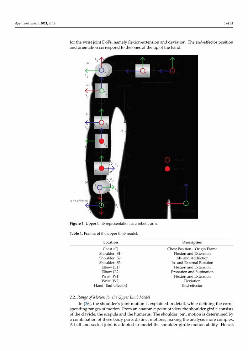
In the present paper the forward kinematics were extracted for the human upperlimb, which was designed as a kinematic chain consisting of three joints, namely, the shoul-der, the elbow and the wrist and 7 DoFs. The shoulder/glenohumeral joint formed bythe humeral head of the scapula and the glenoid cavity [35], performs three rotationalDoFs: the flexion-extension one, abduction-adduction, and at last the internal-externalrotation. The elbow can be represented as a hinge joint permitting elbow flexion-extension.The bones, muscles and ligaments structure in the elbow joint close area restricts its mobil-ity. Nevertheless, a second DoF that originates a bit distal from the elbow is responsible forthe pronation-supination of the forearm. Regarding the wrist joint, two DoFs are present,performing flexion-extension and deviation, respectively. The described kinematic chainused to model the human upper limb, is illustrated in Figure 1.
The coordinate frames were defined for each DoF, with respect to a set of rules fromrobotics theory and the DH configuration convention. These are presented in Figure 1 andsummarized in Table 1. The origin point of the kinematic chain is located at the human’schest. The corresponding coordinate frame is noted as {C} and is also regarded as the originone. The shoulder joint’s 3 DoFs follow with the frames {S1}, {S2} and {S3} assigned onthem denoting the flexion-extension, abduction-adduction and internal-external rotation,accordingly. The elbow rotational DoFs are depicted as {E1} and {E2} frames accounting forthe flexion-extension and pronation-supination DoFs, while {W1} and {W2} frames stand
Appl. Syst. Innov. 2021, 4, 14 5 of 24
for the wrist joint DoFs, namely flexion-extension and deviation. The end-effector positionand orientation correspond to the ones of the tip of the hand.
θ1
Z0
Y0
X2
O3=O4
Xw
Zw
Yw
outwards
inwards
World Coordinate System
lc
{C}
X0
{S1}X1
Y1Z1
θ2
O0=O1=O2Y2
θ3
{S2}
{S3}
Z3X3
Y3{E1}
Y7
X4Y4
Z4
θ5
{E2}
X5
Y5Z5
{W1}
O5=O6Z6
X6
Y6
{W2}
θ6
θ7
Z7 X7
{End-effector}O7
lua
lfa
lh
Xc
Yc
Zc
θ4
Z2
Figure 1. Upper limb representation as a robotic arm.
Table 1. Frames of the upper limb model.
Location Description
Chest {C} Chest Position—Origin FrameShoulder {S1} Flexion and ExtensionShoulder {S2} Ab- and AdductionShoulder {S3} In- and External Rotation
Elbow {E1} Flexion and ExtensionElbow {E2} Pronation and SupinationWrist {W1} Flexion and ExtensionWrist {W2} Deviation
Hand {End-effector} End-effector
2.2. Range of Motion for the Upper Limb Model
In [36], the shoulder’s joint motion is explained in detail, while defining the corre-sponding ranges of motion. From an anatomic point of view the shoulder girdle consistsof the clavicle, the scapula and the humerus. The shoulder joint motion is determined bya combination of these body parts distinct motions, making the analysis more complex.A ball-and-socket joint is adopted to model the shoulder girdle motion ability. Hence,
Appl. Syst. Innov. 2021, 4, 14 6 of 24
the shoulder is described by 3 DoFs, permitting shoulder abduction-adduction motion,flexion-extension and internal-external rotation.
The elevation plain of upper limb defines the kind of exercise that the subject exe-cutes. The elevation plane of 0◦ denotes the upper limb elevation over the frontal plane.In this case, the abduction-adduction of the upper limb occurs with the correspondingrange of motion being [0◦, 180◦]. The elevation plane of 90◦ indicates that the shoulderflexion-extension takes place. The corresponding range of motion is [0◦, 180◦] duringelevation through flexion and [0◦,−60◦] for the shoulder’s elevation through extension(hyperextension). In both cases, the rotation of 0◦ is defined for an upper limb posture withits shaft parallel to the thorax vertical axis. The upper arm internal-external rotation isperformed when the shoulder’s elevation angle is 0◦ and the elbow is flexed at 90◦, leadingthe forearm to be lying in the sagittal plane. The range of motion for this shoulder’s DoFthat accomplishes the upper arm internal-external rotation is [−90◦, 20◦], with the negativevalue being when the upper arm rotates internally towards the human body.
The elbow joint main rotation is performed around a fixed axis that is located amongthe center point of the trochlear sulcus and the center point of the capitulum of the humerus.This DoF permits the elbow flexion-extension with a range of 0◦ for the case of the fullextension for the elbow to 130◦ depicting its flexion. Furthermore, a second rotation occursa bit distal from the elbow joint, which is responsible for the forearm pronation-supinationmotion. In this case, the forearm rotates around an axis that is defined among the centerpoints of the radial head and the distal ulna. The range of this motion is 90◦ for thepronation case to −90◦ for the supination one. The forearm neutral position, where itsrotation is 0◦, occurs when having the shoulder and also the wrist at their neutral positions,the hand is lying in the sagittal plane.
At last, the motion of the wrist joint around the axes that are defined in [37], allow forthe wrist flexion-extension and wrist deviation. The first ranges from −70◦ for the case ofextension to 70◦ for the wrist flexion. The wrist deviation is defined as radial and ulnar.In the radial, the wrist deviates internally towards the body and till −10◦, while duringthe ulnar deviation the wrist deviates outwards of the body and to an upper limit of 25◦.The neutral position of 0◦ for both flexion and deviation DoFs of the wrist occurs when thethird metacarpal and the longitudinal axis of the forearm are aligned.
Taking into account the previous assumptions, the ranges of motion for the upperlimb degrees of freedom of our model are summarized in Table 2.
Table 2. Upper limb DoFs ranges of motion.
Motion DoF Range
Shoulder extension-flexion −60◦–180◦
Shoulder adduction-abduction 0◦–180◦
Shoulder internal-external rotation −90◦–20◦
Elbow extension-flexion 0◦–130◦
Elbow supination-pronation −90◦–90◦
Wrist extension-flexion −70◦–70◦
Wrist radial-ulnar deviation −10◦–25◦
2.3. Dh Parameters of Upper Limb Model
To describe the forward kinematics of the upper limb model, the DH parametershave to be derived. A quadruple of such parameters represent the relation among twosequential coordinate frames of the kinematic chain model. In Table 3, the DH parametersare presented, describing the model configuration that is depicted in Figure 1. The variableslc, lua, l f a and lh stand for the length from the chest to the shoulder joint, the upper armlength and the forearm and hand lengths, respectively. The estimation of these lengthsis based on biomechanics literature [35] and correspond to appropriate fractions of thehuman height H. Hence, if these parameters cannot be measured, the estimation of the
Appl. Syst. Innov. 2021, 4, 14 7 of 24
upper limb segments’ lengths are given by: lc = 0.129 ∗ H, lua = 0.186 ∗ H, l f a = 0.146 ∗ Hand lh = 0.108 ∗ H.
Table 3. DH parameters for the 7 DoF robotic arm.
Frames Links ai αi di θi
{C} 0 0 0 lc −90°
{S1} 1 0 90° 0 θ1 + 90°
{S2} 2 0 90° 0 θ2 + 90°
{S3} 3 0 90° −lua θ3 + 90°
{E1} 4 0 90° 0 θ4 + 180°
{E2} 5 0 −90° −l f a θ5
{W1} 6 0 90° 0 θ6 − 90°
{W2} 7 −lh 90° 0 θ7
The Aii−1 of Equation (1) corresponds to the transformation matrix between the two
sequential coordinate frames i− 1 and i:
Aii−1 =
cθi −sθicαi sθisαi aicθisθi cθicαi −cθisαi aicθi0 sαi cαi di0 0 0 1
(1)
where s and c represent sine and cosine of the corresponding angle and the four quantitiesθi, αi, di, and ai are parameters associated with link i and joint i. These four parameters ofEquation (1) are generally given the names joint angle, link twist, link offset and link length,respectively, and represent specific aspects of the geometric relationship between twocoordinate frames [38]. Since the matrix Ai
i−1 is a function of a single variable, as shownin Table 3, it concludes that the three out of the four parameters for a link have constantvalues and the only variable is θi or di in case of a revolute or a prismatic joint, accordingly.
The transformation matrix from the chest position, where the origin frame is assumed,to the end-effector T7
0 is given by Equation (2).
T70 = ∏7
i=0 Aii−1 (2)
3. DoFs Angles Estimation
Having modeled the upper limb as described in the previous Section, we presenta methodology to estimate the angles’ values of the defined DoFs for the upper limbmodel. This methodology starts using the inertial sensors measurements. If a 9-DoF inertialsensor is attached on a link of upper limb, the gathered measurements during this link’smotion could give the link orientation in the 3D space. The calculation approach, which isdescribed in the sequel, assumes that the coordinate frames of the sensor node resemblethese of the MPU-9150 [39]. In case of a different sensor or coordinate frames configuration,the mathematical equations should be modified accordingly. Furthermore, an importantstep before the extraction of the orientation is the filtering process, as these are calculatedby the raw sensors data, which suffer from gyroscopes drifting and accelerometers noise.
Nevertheless, the calculation of each individual segment orientation is insufficient forthe estimation of the human upper limb posture and orientation in the 3D space. Hence,in the proposed methodology, the orientation of each upper limb link is initially estimatedindividually based on the corresponding sensor node. Then, as each link is a part of thedescribed in the previous Section upper limb model, we manage to get the related DoFsangles in a closed form. The intermediate calculation steps for each upper limb segmentand the corresponding joints angles (3 DoFs for shoulder, 2 for elbow and 2 for wrist)
Appl. Syst. Innov. 2021, 4, 14 8 of 24
are presented in Sections 3.2–3.4. At the last step, the calculated joint angles θi are usedto solve the Forward Kinematics of the upper limb model, following the procedure thatwas presented in Section 2. Thus, the reconstruction and representation of the upper limbmotion in the 3D space is finally accomplished.
3.1. Sensor Fusion and Orientation Estimation
The sensor node orientation can be estimated either by integrating the angular veloci-ties or by processing the accelerometer measurements and estimating the gravity vector.However, to avoid the accumulative errors due to the integration of the gyroscope measure-ments and to minimize the noise in the orientation vector derived from the accelerometersignal, both estimators are implemented and fused over a complementary filter [40,41].Although, there are improved versions of the complementary filter [42–44], we used thissimpler version, which concludes to satisfactory results regarding the experimental testcases, while it also provides quick and accurate performance [45]. In the sequel, the es-timation and filtering procedure that concludes to the calculation of links orientation ispresented in detail.
The simplest method to extract the orientation angles of an IMU-based sensor node isby integrating the measurements of its gyroscope adopting the first-order approximationof Taylor series:
φ[n] = φ[n− 1] +δφg[n]
δtT
θ[n] = θ[n− 1] +δθg[n]
δtT
ψ[n] = ψ[n− 1] +δψg[n]
δtT
(3)
where φ, θ and ψ are the roll, pitch and yaw rotations around y—the longitudinal, x—thetransverse and z—the vertical axes of the sensor, and T is the sampling period. In ourimplementation the value of T is constant, but filtering with variable sampling periods canalso be adopted.
The rates of Euler angles that are presented as coefficients in Equation (3), are givenby the first-order differential equations [30] as:
δφgδt
δθgδt
δψgδt
=
sφasθa
cθa1 cφasθa
cθa
cφa 0 −sφa
sφacθa
0 cφacθa
Gx
Gy
Gz
(4)
where Gx, Gy, Gz are the measurements of the gyroscope for x, y and z axis, respectivelyand s and c represent sine and cosine of the corresponding angle.
The transformation from the raw gyroscope measurements with respect to the sensorbody axis coordinate system to the fixed coordinate system is derived from the directioncosine matrix shown in Equation (4). This relation allowed to update the orientation ofthe upper limb link with time, improving also its accuracy, compared to the previousimplementation [29], where we used the raw gyroscope measurements in the calculations.Using the raw measurements, we get the angular velocities with respect to the moving bodyframe and not the fixed 3-dimensional global frame that is defined. This is the reason whichrestricted us from testing successively the full range of the motions, which were presentedin our previous work, and instead we presented the half range of motions, compared tothe results that we will present in the sequel, in Section 4.
The parameters φa, θa and ψa are the orientation Euler angles that are estimated fromthe accelerometer measurements. Due to the discrete integration (Equation (3)), the errorsand the sensor noise result to the angular error, known as drift.
Appl. Syst. Innov. 2021, 4, 14 9 of 24
These orientation angles can be retrieved by identifying the direction of the gravityvector for a Ry(φ)Rx(θ)Rz(ψ) configuration [46] as:
φa = atan2(
Ax
Az
)θa = atan2
(Ay√
A2x + A2
z
) (5)
where Ax, Ay, Az correspond to accelerometer measurements over x, y and z axis. The
atan2(Y, X) denotes the operation arctan(
YX
)of inverse tangent, which accept solutions
in the angle range of[−π
2 , π2]. The estimation of the rotation ψa in z axis is derived from
the compass measurements along with the already estimated orientation angles φa and θa,as shown in the following equation. This is performed in order to improve the accuracy ofthe rotation estimation in this axis:
ψa = atan2(Cy, Cx
)(6)
where
Cx = Mx cos (φa) + My sin (φa) sin (θa) + Mz sin (φa) cos (θa)
Cy = My cos (θa)−Mz sin (φa)(7)
and the parameters Mx, My, and Mz represent the compass measurements along thecorresponding axes.
Subsequently, sensors’ orientation can be estimated based on the gyroscope mea-surements on a short-term horizon, due to the resulting drifting, and by relying on theaccelerometer and magnetometer measurements for a long-term orientation estimation.
A complementary filter is suggested, in order to provide more accurate estimations ofthe orientation angles for the sensor node. This filter accounts for drifting compensationand noise reduction and is formed as:
φ[n] =
[φ[n− 1] +
δφg[n]δt
T
]k + (1− k)φa[n]
θ[n] =
[θ[n− 1] +
δθg[n]δt
T
]k + (1− k)θa[n]
ψ[n] =
[ψ[n− 1] +
δψg[n]δt
T
]k + (1− k)ψa[n]
(8)
Thus, concluding to the next form taking into account the Equations (3), (5) and (6):
φ[n] =
[φ[n− 1] +
δφg[n]δt
T
]k + (1− k)atan2
(Ax[n]Az[n]
)
θ[n] =
[θ[n− 1] +
δθg[n]δt
T
]k + (1− k)atan2
(Ay[n],
√Ax[n]2 + Az[n]2
)
ψ[n] =
[ψ[n− 1] +
δψg[n]δt
T
]k + (1− k)atan2
(Cy[n], Cx[n]
)(9)
where k ∈ (0.5, 1) is a variable weighting the effect of its term and its typical value is closeto 1.
Appl. Syst. Innov. 2021, 4, 14 10 of 24
3.2. Estimation of the Shoulder Joint Angles
The collected motion data from the IMU, mounted on the upper limb segments,are filtered and processed, as described in Section 3.1. Hence, the orientation of all theindividual links and for each timestamp is determined in terms of the extracted roll, pitchand yaw angles. Using these orientation angles, the direction cosine matrix is calculated foreach upper limb segment, specifying also the required rotation sequence. This is a dynamicprocedure and takes place for every timestamp that updated inertial measurements arereceived by the sensor nodes.
Having described before the shoulder joint as a spherical wrist configuration fora robotic arm model [38], the shoulder joint angles’ variables θ1, θ2 and θ3 can be as-signed to the roll, pitch and yaw angles, with respect to the coordinate frame O0x0y0z0(Figure 1). The mathematical expressions that relate the two sets of angles, result from thefollowing analysis.
The shoulder joint rotations are described by a sequence of the three elemental rota-tions that occur around the axes of the origin coordinate system, which remains motionless,adopting the convention of the Tait-Bryan angles [47]. The sequence of elemental rotationsis important in the estimation process. So, in case of a different definition in the sequenceof the elemental rotations, the corresponding transformation matrix representation mustbe re-estimated.
The orientation transformation among the origin frame 0 and the frame 4 of theupper limb model (Figure 1) is given by the Equation (10). This equation results from thetransformation matrix T4
0 of the forward kinematics based on the DH parameterization.On the other side, the corresponding representation for the Tait-Bryan angles ZαXβYγ
configuration has the form of Equation (11). X, Y and Z are the transformation matrices ofthe elemental rotations around the fixed frame axes x, y and z, accordingly. Hence, thisequation represents an angle α rotation around z axis, followed by an angle β rotationaround x axis and, an angle γ rotation around y axis of the fixed frame.
R40 =
sθ1cθ3 + cθ1sθ2sθ3 cθ1cθ2 sθ1sθ3 − cθ1sθ2cθ3−cθ1cθ3 + sθ1sθ2sθ3 sθ1cθ2 −cθ1sθ3 − sθ1sθ2cθ3
−cθ2sθ3 sθ2 cθ2cθ3
(10)
R = ZαXβYγ =
cαcγ− sαsβsγ −sαcβ cαsγ + sαsβcγsαcγ + cαsβsγ cαcβ sαsγ− cαsβcγ−cβsγ sβ cβcγ
(11)
The parameter α of Equation (11) should not be confused with the Denavit-Hartenbergparameter α noted in Table 3 and Equation (1). Solving over the corresponding items of thematrices presented in Equations (10) and (11), we conclude to the results of Equation (12):
θ1 = α + pi/2
θ2 = β
θ3 = γ
(12)
By replacing the estimated values of angles θ1, θ2 and θ3 in the transformation matrixT4
0 , the posture of the upper arm is extracted with respect to the OCxCyCzC coordinateframe, as it is defined in Figure 1.
3.3. Estimation of the Elbow Joint Angles
The position and orientation of the elbow joint, as it is the distal point of the upperarm, can be estimated from the upper arm position and orientation as shown in Section 3.2.Following a similar approach for the motion data, which are collected by the sensor node thatis attached to the human’s forearm, the orientation of this segment is extracted in terms ofroll, pitch and yaw angles. The kinematic model variables that relate to the elbow joint are the
Appl. Syst. Innov. 2021, 4, 14 11 of 24
angles θ4 and θ5. The elbow joint revolute DoFs can be estimated from the orientation angles,taking into account the representation of Equation (11) for the Tait-Bryan angles, as:
θ4 = atan2(−R(3, 1),R(3, 3)) (13)
θ5 = atan2(−R(1, 2),R(2, 2)) (14)
By replacing these estimated angles’ values in the transformation matrix T64 , the posture
of the forearm is extracted with respect to the O3x3y3z3 coordinate frame (Figure 1).
3.4. Estimation of the Wrist Joint Angles
The wrist joint rotations θ6 and θ7 of the kinematic model can be derived by a similarprocedure as following:
θ6 = atan2(R(3, 1),−R(3, 3)) (15)
θ7 = atan2(R(1, 2),−R(2, 2)) (16)
Hence, by the transformation matrix T86 , the posture of the hand is extracted with
respect to the O5x5y5z5 coordinate frame (Figure 1).
4. System Implementation and Experimental Results4.1. Motion Sensors
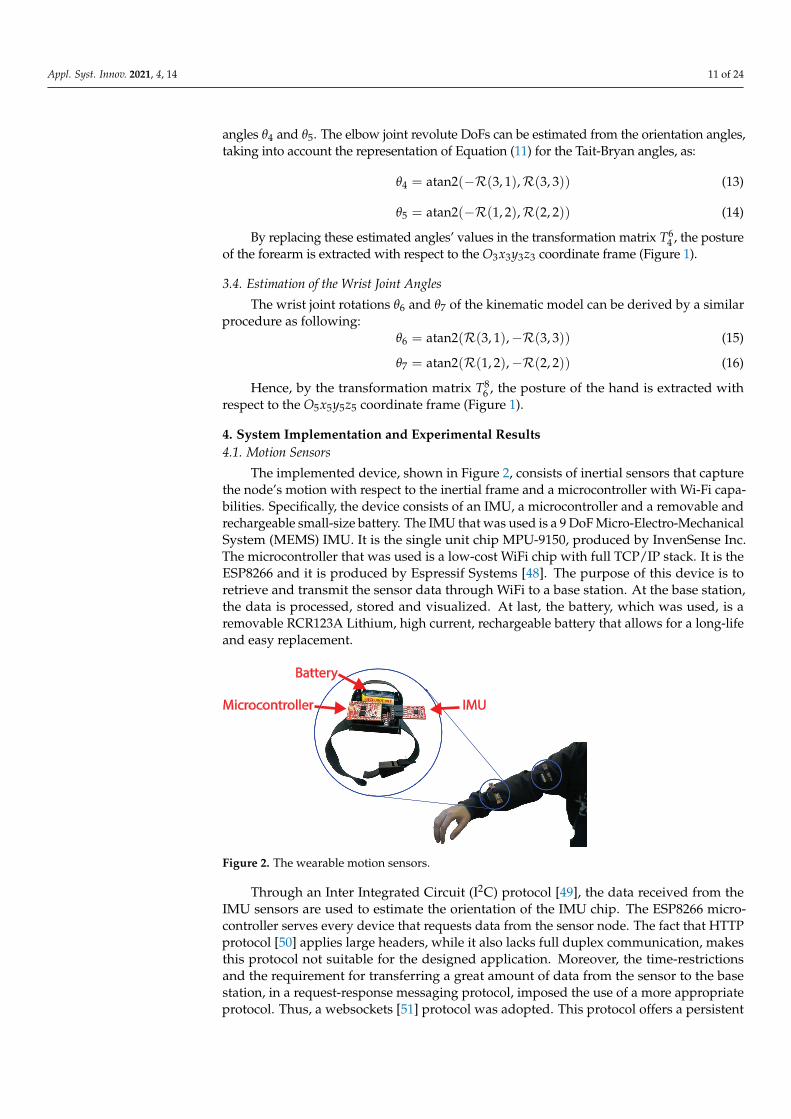
The implemented device, shown in Figure 2, consists of inertial sensors that capturethe node’s motion with respect to the inertial frame and a microcontroller with Wi-Fi capa-bilities. Specifically, the device consists of an IMU, a microcontroller and a removable andrechargeable small-size battery. The IMU that was used is a 9 DoF Micro-Electro-MechanicalSystem (MEMS) IMU. It is the single unit chip MPU-9150, produced by InvenSense Inc.The microcontroller that was used is a low-cost WiFi chip with full TCP/IP stack. It is theESP8266 and it is produced by Espressif Systems [48]. The purpose of this device is toretrieve and transmit the sensor data through WiFi to a base station. At the base station,the data is processed, stored and visualized. At last, the battery, which was used, is aremovable RCR123A Lithium, high current, rechargeable battery that allows for a long-lifeand easy replacement.
IMUMicrocontroller
Battery
Figure 2. The wearable motion sensors.
Through an Inter Integrated Circuit (I2C) protocol [49], the data received from theIMU sensors are used to estimate the orientation of the IMU chip. The ESP8266 micro-controller serves every device that requests data from the sensor node. The fact that HTTPprotocol [50] applies large headers, while it also lacks full duplex communication, makesthis protocol not suitable for the designed application. Moreover, the time-restrictionsand the requirement for transferring a great amount of data from the sensor to the basestation, in a request-response messaging protocol, imposed the use of a more appropriateprotocol. Thus, a websockets [51] protocol was adopted. This protocol offers a persistent
Appl. Syst. Innov. 2021, 4, 14 12 of 24
TCP/IP connection, while client and server can exchange packets, avoiding to burden thecommunication channel with a large volume of irrelevant data.
Each sensor node requires a calibration process before the first use. There are 3 sensorsin the node and there is a different procedure for each sensor. For the magnetometer weshould rotate the sensor multiple times at different directions. We store only the minimumand the maximum value on each axis. Having rotated for a while, we find the offset ofeach axis by taking the mean value of the maximum and minimum values for that axis.Then, we subtract this offset by the measurements. For the gyroscope, letting the device ona surface for a few seconds can produce the mean value of the sensor, which is supposedto be zero. Thus, we subtract this mean value from each measurement, in order to get thecorrect angular rotation of the device. The accelerometer calibration needs to lay the sensorwith all its faces down. Hence, the gravity vector can be identified on each axis, and thevalues are saved on the microcontroller.
During the experimental sessions, a motion capturing sensor node is mounted on theouter side of the selected upper limb segment with the Y axis of the sensor being alignedwith the longitudinal axis of the segment. The right placement of the sensor is ensuredusing a special designed fabric case, which is strapped in the circumference of the limbsegment. Then, the sensor is switched on and the communication with the base station isestablished. The objectives are the acquisition, storing and concurrent visualization of thenode’s IMU measurements during the subject’s exercise session.
Concurrently, a Shimmer3 sensor node [26] has been aligned with the custom-madesensor, proposed in this work, and both were attached to the human’s upper limb segments.A custom-made piece with two sockets was used to successfully align these two sensors.The measurements form Shimmer3 sensor node were captured directly into Matlab® usingthe Shimmer Matlab Instrument Driver. This driver is provided by the correspondingcompany and establishes the communication with the device via the Bluetooth protocol.Before the motion capturing session, the Shimmer3 units were calibrated using the Shimmer9DOF Calibration Application, that is also derived by the same company. This applicationimplements an automated process that calculates the calibration parameters for Shimmer’sintegrated accelerometers, gyroscopes and magnetometers sensors. These calibrationparameters are finally stored in the unit memory, so as the sensor measurements can beautomatically corrected before they are sent to the paired device (e.g., a computer thatfunctions as base station).
In the sequel, the collected sensors measurements, for both type of sensors, are pro-cessed and filtered as described in the previous Section. Then, the DoFs rotations θi, for theupper limb model, are extracted by Equation (12) for the shoulder, Equations (13) and (14)for the elbow and Equations (15) and (16) for the wrist joint, respectively. In the followingSubsections, the 3D reconstructed upper limb joints trajectories are presented in common re-habilitation exercises, as the elbow’s flexion-extension, the shoulder’s abduction-adductionand the wrist’s flexion-extension exercise. In the processing stage, the sensor’s samplingperiod is selected as T = 20 msec, while the values of the model lengths are defined aslc = 0.2322 m, lua = 0.3348 m, l f a = 0.2628 m and lh = 0.1944 m, which were estimatedfor the subject’s height of H = 1.80 m. Furthermore, the first two experimental cases donot account for any wrist rotation, since there was not any sensor node attached over thesubject’s hand. Hence, the corresponding DoFs angles are assumed as θ6 = θ7 = 0◦.
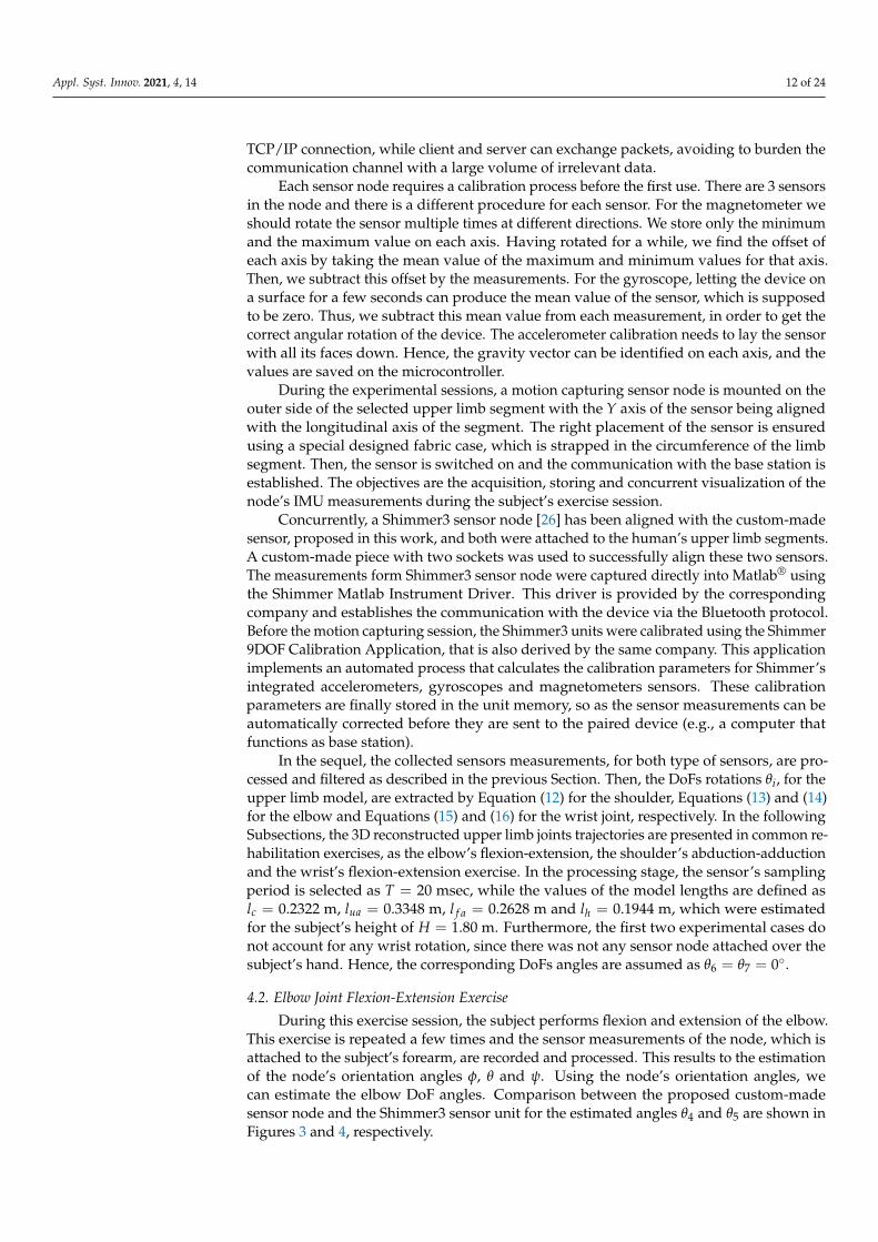
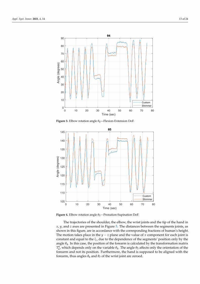
4.2. Elbow Joint Flexion-Extension Exercise
During this exercise session, the subject performs flexion and extension of the elbow.This exercise is repeated a few times and the sensor measurements of the node, which isattached to the subject’s forearm, are recorded and processed. This results to the estimationof the node’s orientation angles φ, θ and ψ. Using the node’s orientation angles, wecan estimate the elbow DoF angles. Comparison between the proposed custom-madesensor node and the Shimmer3 sensor unit for the estimated angles θ4 and θ5 are shown inFigures 3 and 4, respectively.
Appl. Syst. Innov. 2021, 4, 14 13 of 24
0 10 20 30 40 50 60 70 80
Time (sec)
0
10
20
30
40
50
60
70
80
90
Angle
(degre
es)
Custom
Shimmer
Figure 3. Elbow rotation angle θ4—Flexion-Extension DoF.
0 10 20 30 40 50 60 70 80
Time (sec)
105
110
115
120
125
130
135
140
145
Angle
(degre
es)
Custom
Shimmer
Figure 4. Elbow rotation angle θ5—Pronation-Supination DoF.
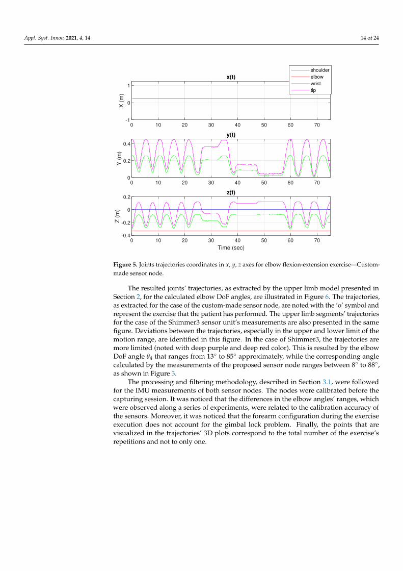
The trajectories of the shoulder, the elbow, the wrist joints and the tip of the hand inx, y, and z axes are presented in Figure 5. The distances between the segments joints, asshown in this figure, are in accordance with the corresponding fractions of human’s height.The motion takes place in the y− z plane and the value of x component for each joint isconstant and equal to the lc, due to the dependence of the segments’ position only by theangle θ4. In this case, the position of the forearm is calculated by the transformation matrixT6
4 , which depends only on the variable θ4. The angle θ5 affects only the orientation of theforearm and not its position. Furthermore, the hand is supposed to be aligned with theforearm, thus angles θ6 and θ7 of the wrist joint are zeroed.
Appl. Syst. Innov. 2021, 4, 14 14 of 24
0 10 20 30 40 50 60 70-1
0
1
X (
m)
x(t)
0 10 20 30 40 50 60 700
0.2
0.4
Y (
m)
y(t)
0 10 20 30 40 50 60 70
Time (sec)
-0.4
-0.2
0
0.2
Z (
m)
z(t)
shoulder
elbow
wrist
tip
Figure 5. Joints trajectories coordinates in x, y, z axes for elbow flexion-extension exercise—Custom-made sensor node.
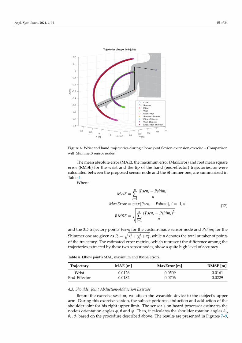
The resulted joints’ trajectories, as extracted by the upper limb model presented inSection 2, for the calculated elbow DoF angles, are illustrated in Figure 6. The trajectories,as extracted for the case of the custom-made sensor node, are noted with the ‘o’ symbol andrepresent the exercise that the patient has performed. The upper limb segments’ trajectoriesfor the case of the Shimmer3 sensor unit’s measurements are also presented in the samefigure. Deviations between the trajectories, especially in the upper and lower limit of themotion range, are identified in this figure. In the case of Shimmer3, the trajectories aremore limited (noted with deep purple and deep red color). This is resulted by the elbowDoF angle θ4 that ranges from 13◦ to 85◦ approximately, while the corresponding anglecalculated by the measurements of the proposed sensor node ranges between 8◦ to 88◦,as shown in Figure 3.
The processing and filtering methodology, described in Section 3.1, were followedfor the IMU measurements of both sensor nodes. The nodes were calibrated before thecapturing session. It was noticed that the differences in the elbow angles’ ranges, whichwere observed along a series of experiments, were related to the calibration accuracy ofthe sensors. Moreover, it was noticed that the forearm configuration during the exerciseexecution does not account for the gimbal lock problem. Finally, the points that arevisualized in the trajectories’ 3D plots correspond to the total number of the exercise’srepetitions and not to only one.
Appl. Syst. Innov. 2021, 4, 14 15 of 24
-0.8
-0.7
-0.6
-0.5
-0.4
-0.3
-0.2
-0.1
0
0Z (m
)
0.1
0.3
0.2
Trajectories of upper limb joints
0.10.2 0.2
X (m) Y (m)
0.1 0.30 0.40.5-0.1
Chest
Shoulder
Elbow
Wrist
End-Eff ector
Shoulder - Shimmer
Elbow - Shimmer
Wrist - Shimmer
End-Eff ector - Shimmer
Figure 6. Wrist and hand trajectories during elbow joint flexion-extension exercise – Comparisonwith Shimmer3 sensor nodes.
The mean absolute error (MAE), the maximum error (MaxError) and root mean squareerror (RMSE) for the wrist and the tip of the hand (end-effector) trajectories, as werecalculated between the proposed sensor node and the Shimmer one, are summarized inTable 4.
Where
MAE =n
∑i=1
|Pseni − Pshimi|n
MaxError = max|Pseni − Pshimi|, i = [1, n]
RMSE =
√√√√ n
∑i=1
(Pseni − Pshimi)2
n
(17)
and the 3D trajectory points Pseni for the custom-made sensor node and Pshimi for the
Shimmer one are given as Pi =√
x2i + y2
i + z2i , while n denotes the total number of points
of the trajectory. The estimated error metrics, which represent the difference among thetrajectories extracted by these two sensor nodes, show a quite high level of accuracy.
Table 4. Elbow joint’s MAE, maximum and RMSE errors.
Trajectory MAE [m] MaxError [m] RMSE [m]
Wrist 0.0126 0.0509 0.0161End-Effector 0.0182 0.0706 0.0229
4.3. Shoulder Joint Abduction-Adduction Exercise
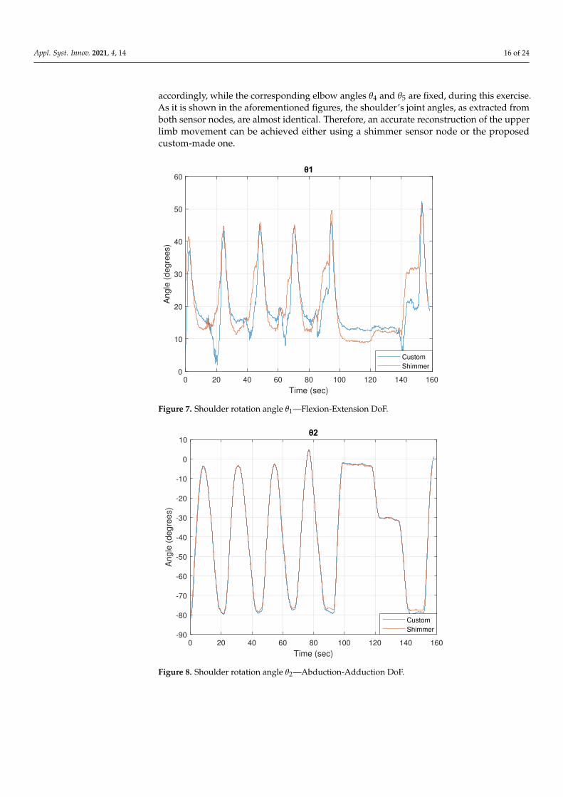
Before the exercise session, we attach the wearable device to the subject’s upperarm. During this exercise session, the subject performs abduction and adduction of theshoulder joint for his right upper limb. The sensor’s on-board processor estimates thenode’s orientation angles φ, θ and ψ. Then, it calculates the shoulder rotation angles θ1,θ2, θ3 based on the procedure described above. The results are presented in Figures 7–9,
Appl. Syst. Innov. 2021, 4, 14 16 of 24
accordingly, while the corresponding elbow angles θ4 and θ5 are fixed, during this exercise.As it is shown in the aforementioned figures, the shoulder’s joint angles, as extracted fromboth sensor nodes, are almost identical. Therefore, an accurate reconstruction of the upperlimb movement can be achieved either using a shimmer sensor node or the proposedcustom-made one.
0 20 40 60 80 100 120 140 160
Time (sec)
0
10
20
30
40
50
60
Angle
(degre
es)
Custom
Shimmer
Figure 7. Shoulder rotation angle θ1—Flexion-Extension DoF.
0 20 40 60 80 100 120 140 160
Time (sec)
-90
-80
-70
-60
-50
-40
-30
-20
-10
0
10
Angle
(degre
es)
Custom
Shimmer
Figure 8. Shoulder rotation angle θ2—Abduction-Adduction DoF.
Appl. Syst. Innov. 2021, 4, 14 17 of 24
0 20 40 60 80 100 120 140 160
Time (sec)
-60
-40
-20
0
20
40
60
Angle
(degre
es)
Custom
Shimmer
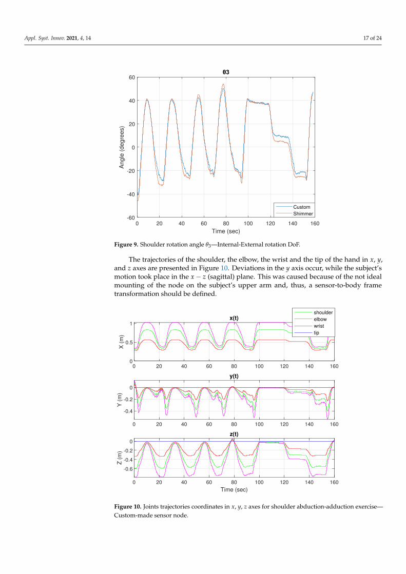
Figure 9. Shoulder rotation angle θ3—Internal-External rotation DoF.
The trajectories of the shoulder, the elbow, the wrist and the tip of the hand in x, y,and z axes are presented in Figure 10. Deviations in the y axis occur, while the subject’smotion took place in the x− z (sagittal) plane. This was caused because of the not idealmounting of the node on the subject’s upper arm and, thus, a sensor-to-body frametransformation should be defined.
0 20 40 60 80 100 120 140 1600
0.5
1
X (
m)
x(t)
0 20 40 60 80 100 120 140 160
-0.4
-0.2
0
Y (
m)
y(t)
0 20 40 60 80 100 120 140 160
Time (sec)
-0.6
-0.4
-0.2
0
Z (
m)
z(t)
shoulder
elbow
wrist
tip
Figure 10. Joints trajectories coordinates in x, y, z axes for shoulder abduction-adduction exercise—Custom-made sensor node.
Appl. Syst. Innov. 2021, 4, 14 18 of 24
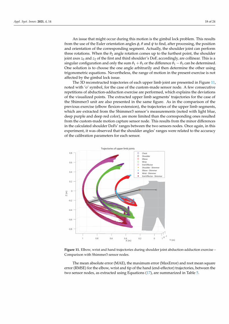
An issue that might occur during this motion is the gimbal lock problem. This resultsfrom the use of the Euler orientation angles φ, θ and ψ to find, after processing, the positionand orientation of the corresponding segment. Actually, the shoulder joint can performthree rotations. When the θ2 angle rotation comes up to the furthest point, the shoulderjoint axes z0 and z2 of the first and third shoulder’s DoF, accordingly, are collinear. This is asingular configuration and only the sum θ1 + θ3 or the difference θ1− θ3 can be determined.One solution is to choose the one angle arbitrarily and then determine the other usingtrigonometric equations. Nevertheless, the range of motion in the present exercise is notaffected by the gimbal lock issue.
The 3D reconstructed trajectories of each upper limb joint are presented in Figure 11,noted with ’o’ symbol, for the case of the custom-made sensor node. A few consecutiverepetitions of abduction-adduction exercise are performed, which explains the deviationsof the visualized points. The extracted upper limb segments’ trajectories for the case ofthe Shimmer3 unit are also presented in the same figure. As in the comparison of theprevious exercise (elbow flexion-extension), the trajectories of the upper limb segments,which are extracted from the Shimmer3 sensor’s measurements (noted with light blue,deep purple and deep red color), are more limited than the corresponding ones resultedfrom the custom-made motion capture sensor node. This results from the minor differencesin the calculated shoulder DoFs’ ranges between the two sensors nodes. Once again, in thisexperiment, it was observed that the shoulder angles’ ranges were related to the accuracyof the calibration parameters for each sensor.
-1
Trajectories of upper limb joints
0
Y (m)
-0.8
1
-0.6
-0.4
0.8
-0.2
0
Z (
m)
0.6
0.2
0.4
X (m)
0.6
0.4
0.8
0.2 0 1
Chest
Shoulder
Elbow
Wrist
End-Effector
Shoulder - Shimmer
Elbow - Shimmer
Wrist - Shimmer
End-Effector - Shimmer
Figure 11. Elbow, wrist and hand trajectories during shoulder joint abduction-adduction exercise –Comparison with Shimmer3 sensor nodes.
The mean absolute error (MAE), the maximum error (MaxError) and root mean squareerror (RMSE) for the elbow, wrist and tip of the hand (end-effector) trajectories, between thetwo sensor nodes, as extracted using Equations (17), are summarized in Table 5.
Appl. Syst. Innov. 2021, 4, 14 19 of 24
Table 5. Shoulder joint’s MAE, maximum and RMSE errors.
Trajectory MAE [m] MaxError [m] RMSE [m]
Elbow 0.0061 0.0462 0.0087Wrist 0.0072 0.0547 0.0103
End-Effector 0.0076 0.0577 0.0109
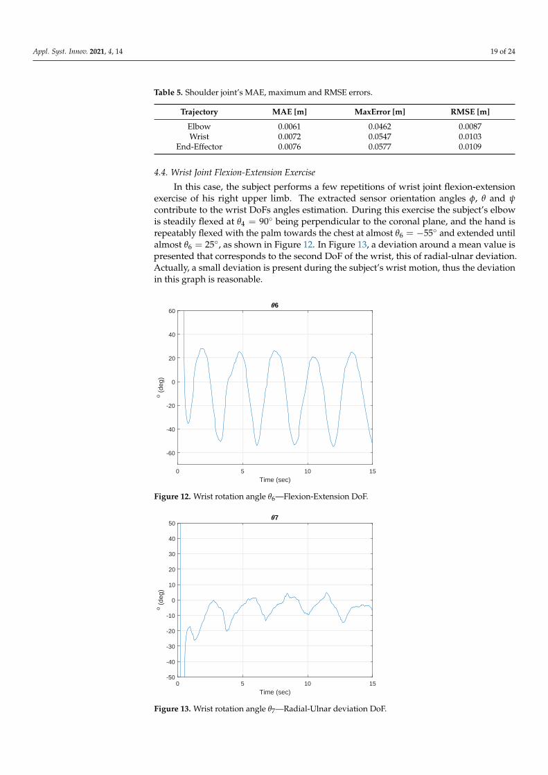
4.4. Wrist Joint Flexion-Extension Exercise
In this case, the subject performs a few repetitions of wrist joint flexion-extensionexercise of his right upper limb. The extracted sensor orientation angles φ, θ and ψcontribute to the wrist DoFs angles estimation. During this exercise the subject’s elbowis steadily flexed at θ4 = 90◦ being perpendicular to the coronal plane, and the hand isrepeatably flexed with the palm towards the chest at almost θ6 = −55◦ and extended untilalmost θ6 = 25◦, as shown in Figure 12. In Figure 13, a deviation around a mean value ispresented that corresponds to the second DoF of the wrist, this of radial-ulnar deviation.Actually, a small deviation is present during the subject’s wrist motion, thus the deviationin this graph is reasonable.
0 5 10 15
Time (sec)
-60
-40
-20
0
20
40
60
o (
deg)
6
Figure 12. Wrist rotation angle θ6—Flexion-Extension DoF.
0 5 10 15
Time (sec)
-50
-40
-30
-20
-10
0
10
20
30
40
50
o (
deg)
7
Figure 13. Wrist rotation angle θ7—Radial-Ulnar deviation DoF.
Appl. Syst. Innov. 2021, 4, 14 20 of 24
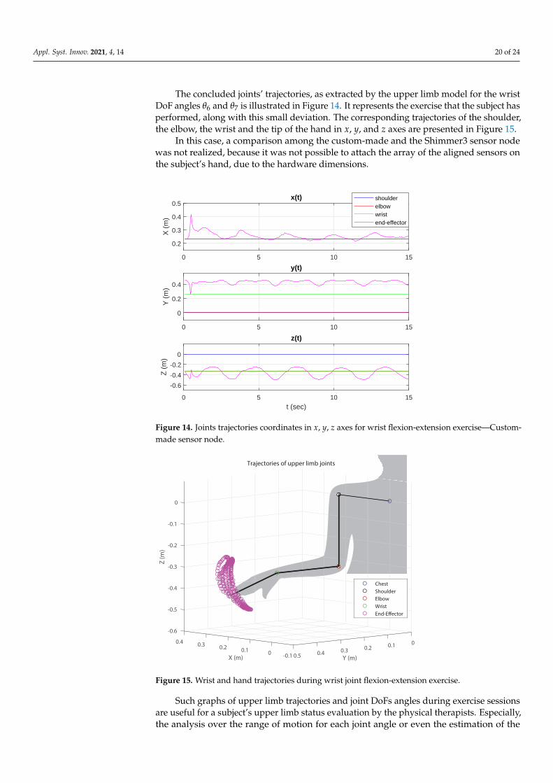
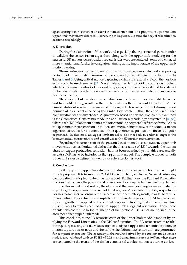
The concluded joints’ trajectories, as extracted by the upper limb model for the wristDoF angles θ6 and θ7 is illustrated in Figure 14. It represents the exercise that the subject hasperformed, along with this small deviation. The corresponding trajectories of the shoulder,the elbow, the wrist and the tip of the hand in x, y, and z axes are presented in Figure 15.
In this case, a comparison among the custom-made and the Shimmer3 sensor nodewas not realized, because it was not possible to attach the array of the aligned sensors onthe subject’s hand, due to the hardware dimensions.
0 5 10 15
0.2
0.3
0.4
0.5
X (
m)
x(t) shoulderelbowwristend-effector
0 5 10 15
0
0.2
0.4
Y (
m)
y(t)
0 5 10 15
t (sec)
-0.6
-0.4
-0.2
0
Z (
m)
z(t)
Figure 14. Joints trajectories coordinates in x, y, z axes for wrist flexion-extension exercise—Custom-made sensor node.
-0.6
-0.5
0.4
-0.4
-0.3
-0.2
0
-0.1
Z (
m)
0
Trajectories of upper limb joints
0.3 0.10.2 0.2
X (m) Y (m)
0.1 0.30 0.40.5-0.1
Chest
Shoulder
Elbow
Wrist
End-Effector
Figure 15. Wrist and hand trajectories during wrist joint flexion-extension exercise.
Such graphs of upper limb trajectories and joint DoFs angles during exercise sessionsare useful for a subject’s upper limb status evaluation by the physical therapists. Especially,the analysis over the range of motion for each joint angle or even the estimation of the
Appl. Syst. Innov. 2021, 4, 14 21 of 24
speed during the execution of an exercise indicate the status and progress of a patient withupper limb movement disorders. Hence, the therapists could tune the sequel rehabilitationsessions accordingly.
5. Discussion
During the elaboration of this work and especially the experimental part, in orderto validate the sensor fusion algorithms along with the upper limb modeling for thesuccessful 3D motion reconstruction, several issues were encountered. Some of them needmore attention and further investigation, aiming at the improvement of the upper limbmotion tracking.
The experimental results showed that the proposed custom-made motion capturingsystem had an acceptable performance, as shown by the estimated error indicators inTables 4 and 5. Using optical motion capturing systems instead, like Vicon, the positionerror would be much smaller [52]. Nevertheless, in order to avoid the occlusion problem,which is the main drawback of this kind of systems, multiple cameras should be installedin the rehabilitation center. However, the overall cost may be prohibited for an averagehealthcare facility.
The choice of Euler angles representation found to be more understandable to handleand to identify failing results in the implementation that then could be solved. At thecurrent status of research, the range of motions, which were performed during the ex-perimental tests, is not affected by the gimbal lock problem. Thus, the adoption of Eulerconfiguration was finally chosen. A quaternion-based option that is currently examinedis the Geometrical Constraints Modeling and Fusion methodology presented in [53,54],where each IMU placement defines the corresponding segment’s reference frame. Whenthe quaternion representation of the sensors’ measurements flow is provided, a fusionalgorithm accounts for the conversion from quaternion sequences into the axis-angularsequences. In this case, an upper limb model is also needed, in order to express thebiomechanical characteristics and contribute to the 3D motion reconstruction.
Regarding the current state of the presented custom-made sensor system, upper limbmovements, such as horizontal abduction that has a range of 130◦ towards the humanchest or scapula protraction-retraction, has not been examined yet. In this case, actually,an extra DoF has to be included in the upper limb model. The complete model for bothupper limbs can be defined, as well, as an extension to this work.
6. Conclusions
In this paper, an upper limb kinematic model that resembles a robotic arm with rigidlinks is proposed. It is formed as a 7 DoF kinematic chain, while the Denavit-Hartenbergconfiguration is adopted to describe this model. Furthermore, the Forward Kinematicsmatrices that can give the position and orientation of each upper limb segment are derived.
For this model, the shoulder, the elbow and the wrist joint angles are estimated byexploiting the upper arm, forearm and hand segments’ orientation vectors, respectively.For this reason, inertial sensors are attached to the upper limb segments, in order to capturetheirs motion. This is finally accomplished by a two steps procedure. At first, a sensorfusion algorithm is applied to the inertial sensors’ data along with a complementaryfilter, in order to extract each individual upper limb’s segment orientation. Then, theseorientations contribute to the estimation of the rotational DoFs that are defined in theaforementioned upper limb model.
This concludes to the 3D reconstruction of the upper limb model’s motion by ap-plying the Forward Kinematics of the DH configuration. The 3D reconstruction results,the trajectory tracking and the visualization of a subject’s upper limb for both the prototypemotion capture sensor node and the off-the-shelf Shimmer3 sensor unit, are performed,for comparison reasons. The accuracy of the results derived by the custom-made sensornode is also validated with an RMSE of 0.02 m and a maximum error of 0.07 m, when theseare compared to the results of the similar commercial wireless motion capturing device.
Appl. Syst. Innov. 2021, 4, 14 22 of 24
These validation results demonstrate the accuracy of the inertial technology based mo-tion analysis, which is presented in this work, and can be a guide for further improvement.The same methodology could also be extended to estimate the lower limb, or the wholebody movements in the 3D space, using additional sensors and similar robotic modeling ofthe human body segments.
Author Contributions: Conceptualization, O.T. and E.D.; methodology, O.T. and K.G.; software,O.T., K.G. and N.E.; investigation, O.T., K.G., N.E. and E.D.; data curation, O.T., K.G. and N.E.;writing–original draft preparation, O.T., K.G. and E.D.; writing–review and editing, O.T., K.G. andE.D.; visualization, O.T. and K.G.; supervision, E.D.; project administration, E.D.; funding acquisition,O.T., K.G., N.E. and E.D. All authors have read and agreed to the published version of the manuscript.
Funding: This work was performed under the framework of the “EDBM34 Call - Support researchfocusing on young researchers” project entitled “Design and implementation of a complementarysensing system for physiotherapy procedure monitoring through smart portable devices” (MIS5005357), co-funded by the European Social Fund (ESF) and National Resources.
Institutional Review Board Statement: Not applicable.
Informed Consent Statement: Informed consent was obtained from all subjects involved in the study.
Data Availability Statement: Not applicable.
Conflicts of Interest: The authors declare no conflict of interest. The funders had no role in the designof the study; in the collection, analyses, or interpretation of data; in the writing of the manuscript,or in the decision to publish the results.
AbbreviationsThe following abbreviations are used in this manuscript:
3D 3-DimensionalCSMA/CA Carrier Sense Multiple Access/Collision DetectionDH Denavit-HartenbergDoF Degrees of FreedomI2C Inter Integrated CircuitIMU Inertial Measurement UnitLoS Line of SightMEMS Micro-Electro-Mechanical SystemOLE Optical Linear EncodersPCA Principal Component AnalysisTDMA Time Division Multiple AccessWSN Wireless Sensor Network
References1. García-Rudolph, A.; Laxe, S.; Sauri, J.; Opisso, E.; Tormos, J.; Bernabeu, M. Evidence of chronic stroke rehabilitation interventions
in activities and participation outcomes: Systematic review of meta-analyses of randomized controlled trials. Eur. J. Phys. Rehabil.Med. 2019, 55, 695–709. [CrossRef] [PubMed]
2. Kwakkel, G.; van Peppen, R.; Wagenaar, R.C.; Dauphinee, S.W.; Richards, C.; Ashburn, A.; Miller, K.; Lincoln, N.; Partridge,C.; Wellwood, I.; et al. Effects of augmented exercise therapy time after stroke: A meta-analysis. Stroke 2004, 35, 2529–2539.[CrossRef]
3. López-Nava, I.H.; Muñoz-Meléndez, A. Wearable Inertial Sensors for Human Motion Analysis: A Review. IEEE Sens. J. 2016,16, 7821–7834. [CrossRef]
4. Zhou, H.; Hu, H. Human motion tracking for rehabilitation-A survey. Biomed. Signal Process. Control 2008, 3, 1–18. [CrossRef]5. Onose, G.; Popescu, N.; Munteanu, C.; Ciobanu, V.; Sporea, C.; Mirea, M.D.; Daia, C.; Andone, I.; Spînu, A.; Mirea, A. Mobile
Mechatronic/Robotic Orthotic Devices to Assist–Rehabilitate Neuromotor Impairments in the Upper Limb: A Systematic andSynthetic Review. Front. Neurosci. 2018, 12, 577. [CrossRef]
6. Maciejasz, P.; Eschweiler, J.; Gerlach-Hahn, K.; Jansen-Troy, A.; Leonhardt, S. A survey on robotic devices for upper limbrehabilitation. J. NeuroEng. Rehabil. 2014, 11, 3. [CrossRef] [PubMed]
7. Yoon, J.; Novandy, B.; Yoon, C.H.; Park, K.J. A 6-DOF gait rehabilitation robot with upper and lower limb connections that allowswalking velocity updates on various terrains. IEEE/ASME Trans. Mechatron. 2010, 15, 201–215. [CrossRef]
Appl. Syst. Innov. 2021, 4, 14 23 of 24
8. Wong, W.Y.; Wong, M.S.; Lo, K.H. Clinical applications of sensors for human posture and movement analysis: A review.Prosthetics Orthot. Int. 2007, 31, 62–75. [CrossRef] [PubMed]
9. Hadjidj, A.; Souil, M.; Bouabdallah, A.; Challal, Y.; Owen, H. Wireless sensor networks for rehabilitation applications: Challengesand opportunities. J. Netw. Comput. Appl. 2013, 36, 1–15. [CrossRef]
10. Gravina, R.; Alinia, P.; Ghasemzadeh, H.; Fortino, G. Multi-Sensor Fusion in Body Sensor Networks: State-of-the-art and researchchallenges. Inf. Fusion 2016, 35, 68–80. [CrossRef]
11. Macedo, P.; Afonso, J.A.; Rocha, L.A.; Simoes, R. A telerehabilitation system based on wireless motion capture sensors. In Proceedingsof the International Conference on Physiological Computing Systems, Lisbon, Portugal, 7–9 January 2014; pp. 55–62.
12. Arnold, D.; Li, X.; Lin, Y.; Wang, Z.; Yi, W.J.; Saniie, J. IoT Framework for 3D Body Posture Visualization. In Proceedings ofthe 2020 IEEE International Conference on Electro Information Technology (EIT), Chicago, IL, USA, 31 July–1 August 2020;pp. 117–120. [CrossRef]
13. Lee, G.X.; Low, K.S.; Taher, T. Unrestrained measurement of arm motion based on a wearable wireless sensor network. IEEETrans. Instrum. Meas. 2010, 59, 1309–1317. [CrossRef]
14. Mazomenos, E.B.; Biswas, D.; Cranny, A.; Rajan, A.; Maharatna, K.; Achner, J.; Klemke, J.; Jöbges, M.; Ortmann, S.; Langendörfer, P.Detecting elementary arm movements by tracking upper limb joint angles with MARG sensors. IEEE J. Biomed. Health Inform.2016, 20, 1088–1099. [CrossRef]
15. Hadjidj, A.; Bouabdallah, A.; Challal, Y. Rehabilitation supervision using wireless sensor networks. In Proceedings of the 2011IEEE International Symposium on a World of Wireless, Mobile and Multimedia Networks (WoWMoM), Lucca, Italy, 20–24 June2011; pp. 1–3.
16. Nguyen, K.D.; Chen, I.M.; Luo, Z.; Yeo, S.H.; Duh, H.B.L. A wearable sensing system for tracking and monitoring of functionalarm movement. IEEE/ASME Trans. Mechatron. 2011, 16, 213–220. [CrossRef]
17. Lim, C.K.; Chen, I.M.; Luo, Z.; Yeo, S.H. A low cost wearable wireless sensing system for upper limb home rehabilitation. InProceedings of the 2010 IEEE Conference on Robotics Automation and Mechatronics (RAM), Singapore, 28–30 June 2010; pp. 1–8.
18. Lim, K.Y.; Goh, F.Y.K.; Dong, W.; Nguyen, K.D.; Chen, I.M.; Yeo, S.H.; Duh, H.B.L.; Kim, C.G. A wearable, self-calibrating, wirelesssensor network for body motion processing. In Proceedings of the IEEE International Conference on Robotics and Automation,Pasadena, CA, USA, 19–23 May 2008; pp. 1017–1022.
19. Jiang, Y.; Qin, Y.; Kim, I.; Wang, Y. Towards an IoT-based upper limb rehabilitation assessment system. In Proceedings of the 201739th Annual International Conference of the IEEE Engineering in Medicine and Biology Society (EMBC), Jeju, Korea, 11–15 July2017; pp. 2414–2417.
20. Papazoglou, P.; Laskari, T.; Fourlas, G. Towards a low cost open architecture wearable sensor network for health care applications.In Proceedings of the 7th International Conference on Pervasive Technologies Related to Assistive Environments, St Petersburg,Russia, 23–25 September 2014; p. 10.
21. Alves, R.C.; Gabriel, L.B.; de Oliveira, B.T.; Margi, C.B.; dos Santos, F.C.L. Assisting physical (hydro) therapy with wirelesssensors networks. IEEE Internet Things J. 2015, 2, 113–120. [CrossRef]
22. Libelium Pushes Its eHealth IoT Platform with a New Cloud and Medical Development Kits. Available online: https://www.libelium.com/libeliumworld/libelium-pushes-its-ehealth-iot-platform-with-a-new-cloud-and-medical-development-kits/ (ac-cessed on 15 December 2020).
23. Deltason Medical Ltd. Available online: www.deltason.com (accessed on 15 December 2020).24. Xsens 3D Motion Tracking. Available online: www.xsens.com (accessed on 15 December 2020).25. The IoT Marketplace. Available online: www.the-iot-marketplace.com/mysignals-sport-performance-monitoring-development-
kit-ble (accessed on 15 December 2020).26. Shimmer Wireless Sensing Technology. Available online: www.shimmer-research.com (accessed on 15 December 2020).27. De Baets, L.; van der Straaten, R.; Matheve, T.; Timmermans, A. Shoulder Assessment according to the International Classification
of Functioning by means of Inertial Sensor Technologies: A Systematic Review. Gait Posture 2017, 57, 278–294. [CrossRef][PubMed]
28. de Lucena, D.S.; Stoller, O.; Rowe, J.B.; Chan, V.; Reinkensmeyer, D.J. Wearable sensing for rehabilitation after stroke: Bimanualjerk asymmetry encodes unique information about the variability of upper extremity recovery. In Proceedings of the 2017International Conference on Rehabilitation Robotics (ICORR), London, UK, 17–20 July 2017; pp. 1603–1608.
29. Tsilomitrou, O.; Gkountas, K.; Evangeliou, N.; Dermatas, E. On the development of a wireless motion capture sensor nodefor upper limb rehabilitation. In Proceedings of the 2019 6th International Conference on Control, Decision and InformationTechnologies (CoDIT), Paris, France, 23–26 April 2019; pp. 1568–1573.
30. Phillips, W.; Hailey, C.; Gebert, G. A review of attitude kinematics for aircraft flight simulation. In Proceedings of the Modelingand Simulation Technologies Conference, Denver, CO, USA, 14–17 August 2000; p. 4302.
31. Marieb, E.N.; Hoehn, K. Human Anatomy & Physiology; Pearson Education: London, UK, 2007.32. Theofanidis, M.; Lioulemes, A.; Makedon, F. A motion and force analysis system for human upper-limb exercises. In Proceedings
of the 9th ACM International Conference on Pervasive Technologies Related to Assistive Environments, Corfu, Greece, 29 June–1July 2016; p. 9.
Appl. Syst. Innov. 2021, 4, 14 24 of 24
33. Peppoloni, L.; Filippeschi, A.; Ruffaldi, E.; Avizzano, C.A. A novel 7 degrees of freedom model for upper limb kinematicreconstruction based on wearable sensors. In Proceedings of the 2013 IEEE 11th International Symposium on Intelligent Systemsand Informatics (SISY), Subotica, Serbia, 26–28 September 2013; pp. 105–110.
34. Ruffaldi, E.; Peppoloni, L.; Filippeschi, A.; Avizzano, C.A. A novel approach to motion tracking with wearable sensors based onprobabilistic graphical models. In Proceedings of the 2014 IEEE International Conference on Robotics and Automation (ICRA),Hong Kong, China, 31 May–7 June 2014; pp. 1247–1252.
35. Ethier, C.R.; Simmons, C.A. Introductory Biomechanics: From Cells to Organisms; Cambridge University Press: Cambridge, UK,2007; pp. 381, 468–470.
36. Holzbaur, K.R.; Murray, W.M.; Delp, S.L. A model of the upper extremity for simulating musculoskeletal surgery and analyzingneuromuscular control. Ann. Biomed. Eng. 2005, 33, 829–840. [CrossRef]
37. Ruby, L.; Conney, W., III; An, K.; Linscheid, R.; Chao, E. Relative motion of selected carpal bones: A kinematic analysis of thenormal wrist. J. Hand Surg. 1988, 13, 1–10. [CrossRef]
38. Spong, M.W.; Vidyasagar, M. Robot Dynamics and Control; John Wiley & Sons: Hoboken, NJ, USA, 2008.39. InvenSense MPU-9150. Available online: www.invensense.com/products/motion-tracking/9-axis/mpu-9150/ (accessed on 15
December 2020).40. Gallagher, A.; Matsuoka, Y.; Ang, W.T. An efficient real-time human posture tracking algorithm using low-cost inertial and
magnetic sensors. In Proceedings of the 2004 IEEE/RSJ International Conference on Intelligent Robots and Systems (IROS) (IEEECat. No. 04CH37566), Sendai, Japan, 28 September–2 October 2004; Volume 3, pp. 2967–2972.
41. Tian, Y.; Wei, H.; Tan, J. An adaptive-gain complementary filter for real-time human motion tracking with MARG sensors infree-living environments. IEEE Trans. Neural Syst. Rehabil. Eng. 2012, 21, 254–264. [CrossRef] [PubMed]
42. Fourati, H. Heterogeneous Data Fusion Algorithm for Pedestrian Navigation via Foot-Mounted Inertial Measurement Unit andComplementary Filter. IEEE Trans. Instrum. Meas. 2015, 64, 221–229. [CrossRef]
43. Valenti, R.G.; Dryanovski, I.; Xiao, J. Keeping a Good Attitude: A Quaternion-Based Orientation Filter for IMUs and MARGs.Sensors 2015, 15, 19302–19330. [CrossRef] [PubMed]
44. Mahony, R.; Hamel, T.; Pflimlin, J. Nonlinear Complementary Filters on the Special Orthogonal Group. IEEE Trans. Autom.Control 2008, 53, 1203–1218. [CrossRef]
45. Gui, P.; Tang, L.; Mukhopadhyay, S. MEMS based IMU for tilting measurement: Comparison of complementary and kalmanfilter based data fusion. In Proceedings of the 2015 IEEE 10th Conference on Industrial Electronics and Applications (ICIEA),Auckland, New Zealand, 15–17 June 2015; pp. 2004–2009. [CrossRef]
46. Pedley, M. High precision calibration of a three-axis accelerometer. Free. Semicond. Appl. Note 2013, 1, AN4399.47. Tait-Bryan Angles. Available online: https://en.wikipedia.org/wiki/Euler_angles (accessed on 15 December 2020).48. Espressif Systems. Available online: www.espressif.com (accessed on 15 December 2020).49. Semiconductors, P. The I2C-bus specification. Philips Semicond. 2000, 9397, 00954.50. Fielding, R.; Gettys, J.; Mogul, J.; Frystyk, H.; Masinter, L.; Leach, P.; Berners-Lee, T. Hypertext Transfer Protocol–HTTP/1.1.
Technical Report. Available online: http://www.rfc-editor.org/rfc/rfc2616.txt (accessed on 17 February 2021).51. Fette, I.; Melnikov, A. The Websocket Protocol. Technical Report. Available online: http://www.rfc-editor.org/rfc/rfc6455.txt
(accessed on 17 February 2021).52. Merriaux, P.; Dupuis, Y.; Boutteau, R.; Vasseur, P.; Savatier, X. A Study of Vicon System Positioning Performance. Sensors 2017,
17, 1591. [CrossRef] [PubMed]53. Zhang, Z.; Huang, Z.; Wu, J. Hierarchical information fusion for human upper limb motion capture. In Proceedings of the 2009
12th International Conference on Information Fusion, Seattle, WA, USA, 6–9 July 2009; pp. 1704–1711.54. Zhang, S.; Jin, W.; Zhang, Y. Implementation and complexity analysis of orientation estimation algorithms for human body motion
tracking using low-cost sensors. In Proceedings of the 2017 2nd International Conference on Frontiers of Sensors Technologies(ICFST), Shenzhen, China, 14–16 April 2017; pp. 49–54.