Embed Size (px)
Citation preview
International Journal “Information Theories and Applications”, Vol. 21, Number 2, 2014
154
WIRELESS DATA TRANSMISSION OPTIONS IN ROTARY IN-DRILLING ALIGNMENT(R-IDA) SETUPS FOR MULTILATERAL OIL DRILLING APPLICATIONS
Zhenhua Wang, Tao Li, Myles McDougall, Dan McCormack, Martin P. Mintchev
Abstract: Conventional methods in multilateral drilling processes incorporate magnetometer-based surveying systems for determining the position and attitude of the bottomhole assembly (BHA). Magnetic surveying results in an increased weight of the BHA, higher cost due to shielding with bulky nonmagnetic collars and, more importantly, severely degraded performance due to unavoidable geomagnetic interferences such as metal and ore deposits in the vicinity. Micro-Electromechanical Systems (MEMS) based Inertial Navigation Systems (INS) have been proposed as an alternative to magnetic surveying for multilateral drilling. Previous studies have shown theoretically and experimentally that a Kalman filter-based In-Drilling Alignment (IDA) and its minimized version Rotary In-Drilling Alignment (R-IDA) successfully limit the accumulated error growth associated with the INS, compared to the traditional zero-velocity update (ZUPT) alignment method. A high performance wireless MEMS-based INS has been proposed for R-IDA alignment, the implementation simplicity and high accuracy of which could be very useful in multilateral drilling processes. Furthermore, this paper discusses the concept of wireless data transmission within drill pipes downhole in comparison to other existing or emerging methods. It is shown that wireless telemetry inside the drill pipes is potentially capable of transmitting up to 250,000 bits per second (bits/sec) with high reliability and low power consumption, which makes a drill string based local network for real-time downhole monitoring and control applications feasible.
Keywords: Multilateral drilling design, wireless data transmission, downhole instrumentation, rotary In-Drilling Alignment.
ACM Classification Keywords: A.0 General Literature - Conference proceedings; J.2 Physical Sciences and Engineering.
Introduction
A. Multilateral oil drilling applications
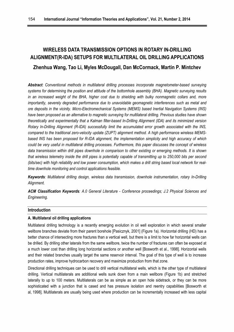
Multilateral drilling technology is a recently emerging evolution in oil well exploration in which several smaller wellbore branches deviate from their parent borehole [Pasicznyk, 2001] (Figure 1a). Horizontal drilling (HD) has a better chance of intersecting more fractures than a vertical well, but there is a limit to how far horizontal wells can be drilled. By drilling other laterals from the same wellbore, twice the number of fractures can often be exposed at a much lower cost than drilling long horizontal sections or another well [Bosworth et al., 1998]. Horizontal wells and their related branches usually target the same reservoir interval. The goal of this type of well is to increase production rates, improve hydrocarbon recovery and maximize production from that zone.
Directional drilling techniques can be used to drill vertical multilateral wells, which is the other type of multilateral drilling. Vertical multilaterals are additional wells sunk down from a main wellbore (Figure 1b) and stretched laterally to up to 100 meters. Multilaterals can be as simple as an open hole sidetrack, or they can be more sophisticated with a junction that is cased and has pressure isolation and reentry capabilities [Bosworth et al, 1998]. Multilaterals are usually being used where production can be incrementally increased with less capital
International Journal “Information Theories and Applications”, Vol. 21, Number 2, 2014
155
costs. They can also be employed for offshore drilling where the numbers of slots are limited [Bosworth et al, 1998].
Figure 1a. Horizontal multilateral oil drilling Figure 1b. Vertical multilateral oil drilling
A successful multilateral well that replaces several vertical wellbores can reduce overall drilling and completion costs, increase production and provide more efficient drainage of a reservoir. Furthermore, multilaterals can make reservoir management more efficient and help increase recoverable reserves.
B. Rotary In-Drilling Alignment (R-IDA) for error compensation in downhole navigation systems
Traditional downhole navigation is based on the so-called Measurement-While-Drilling (MWD) systems, which incorporate triad orthogonal accelerometers and triad orthogonal magnetometers to determine the position and altitude of the bottomhole assembly (BHA). However, the magnetometers are susceptible to external magnetic interferences, including randomly located ore deposits, drill string rotations and drilling fluid circulations [Shelkholeslami et al, 1991; Torkildsen et al, 2004]. Typically, magnetic interferences are addressed by shielding the BHA with very expensive and bulky nonmagnetic collars, which can only minimize, rather than eliminate magnetic artifacts. Degradation of the magnetometers is sometimes dramatic and the oil industry has to employ alternative wireline gyroscopes to determine BHA’s attitude, which costs it tremendous time and money.
An inertial navigation system (INS) is autonomous dead-reckoning (DR) approach of tracking the position and orientation of an object by 3 mutually perpendicular accelerometers and 3 mutually perpendicular gyroscopes, which are not influenced by magnetic interferences. Commercially available Micro-Electromechanical Systems (MEMS)-based inertial measurement units (IMU) that contain accelerometers and gyroscopes are excellent candidates for complete INS due to their low cost, small size and low power consumption, which are critical factors for downhole drilling. However, the unlimited error growth in the measurements might be prohibitive for the long-term utilization of this technology. New methods to reduce the INS error include In-Drilling Alignment (IDA) [Jurkov et al, 2011] and its reduced version, Rotary In-Drilling Alignment (R-IDA) [Wang et al, 2013], which are both utilized to increase the observability for their Kalman filters (KF) by precisely inducing controlled motions during operational breaks in the drilling process. Previous study [Wang et al, 2013] has shown that a MEMS-based autonomous IMU produced by Memsense LLC (Rapid City, SD, USA) employing the R-IDA method achieved error reduction 2 times greater than the same device utilizing the mainstream error compensation method known as zero-velocity update (ZUPT). However, these results were obtained in laboratory conditions,
International Journal “Information Theories and Applications”, Vol. 21, Number 2, 2014
156
and the autonomous Memsense IMU noise and temperature characteristics were not adequate for real downhole oil drilling applications.
C. Problems of data transmission in downhole navigation
Harsh downhole environment encountered in drilling applications presents particular challenges, especially for reliable data transmission between the surface and the drilling devices due to the high pressure, extreme temperatures and huge distances downhole. At the bottom of the drill string is the BHA, which includes the drill bit along with electronic components such as sensors, control mechanisms and required circuitry [PetroWiki, 2013]. The sensors in the BHA typically contain surveying of various properties of the formation and the fluid within it as well as the navigation measurements. The processes that require information from such downhole sensors include MWD and Logging-While-Drilling (LWD) systems. Once MWD/LWD logs the downhole parameters and measurements, there are mainly three methods to pull the information upward. They are discussed separately below.
Mud-pulse telemetry (MPT)
Mud-pulse telemetry (MPT) is the most common and standard method of data transmission downhole and is especially used by MWD/LWD tools developed in the 1970’s [Wasserman et al., 2008]. The conventional MWD/LWD tool incorporates an electronic sensors package and a mudflow wellbore telemetry device. The drilling fluid called mud is pumped from the surface to the downhole BHA along the drill string. The mud serves as a cooling and lubricating circulation fluid and continuously carries the derbies back up to the ground during the drilling process. The mudflow wellbore telemetry device can selectively restrict the passages of the mud through the drill string to control and manipulate the pressure in the mud lines by operating a valve. These manipulations create pressure fluctuations which represent information that is being encoded in binary format and propagated within the mud towards the surface where it is received from pressure transducers [Wasserman et al., 2008]. The problems with this type of data transmission are exactly two: (1) slow speed of the serial mud-based interface; and (2) high power consumption.
Electromagnetic telemetry (EMT)
Electromagnetic telemetry (EMT) employs a downhole current source to emit an electromagnetic signal into a formation. The signal can be detected and received at the surface due to a small voltage drop between the top part of the BHA (the main drill string) and the bottom part of the BHA. Typically, the EM tool can generate voltage difference between the drill string sections at a very low frequency, below 30 Hz [Gao et al, 2006]. The information then is converted into modulated EM waves by digital modulation. The typical transmission rate of the EMT tool is around 10 bits/sec. Compared to the MPT, the EMT method does not require changes in major drilling parameters such as rotation of the drill pipe and mud flow rate, to send information to the surface. It also does not rely on the composition of the mud flow, since most of the mud is compressed, gas-filled fluid for the underbalanced drilling (UBD) in order to reduce the equivalent density. This results in high signal attenuation during the data transmission that severely handicaps the MPT’s communication capability. EMT tool is usually employed for certain specific applications such as UBD because of its immunity to the drilling fluid. However, EMT can also lose strength dramatically in some types of formations, becoming unpredictable at several thousand feet of depth [Gao et al., 2006]. Its cost is also significant.
Wired cable data transmission
Some research has been focusing on the development of wired drill pipe system since the beginning of the 21st century [National Oilwell Varco, 2014; Jellison et al., 2003]. It is based on the theory that composite drill pipes can also facilitate high-speed data transfer rates via special materials such as fiber optic cables embedded within the pipes during construction. A great benefit of such system is its superior data transmission rate which makes a
International Journal “Information Theories and Applications”, Vol. 21, Number 2, 2014
157
real-time monitoring system downhole in drilling completely feasible. The IntelliServ wired pipe, offering data rates upwards of 1 million bits/sec became commercial in 2006 [National Oilwell Varco, 2014]. However, cables can cause reliability problems attributed to installation, connections and drilling fluid migration. In addition, the high capital costs and lack of advanced technology in drill pipe material and manufacturing is still limiting its development.
Since the data transmission rate of the MPT and EMT correlated with bandwidth is less than 100 bits/sec [Jellison et al, 2003], most of the useful information provided by the MWD and LWD will be lost or stored in a memory logger associated with the downhole instrumentation near the drill bit. Therefore, the so-called “real-time drilling” can be applied in a very limited scope. Comparisons of the commercialized downhole transmission methods are given below (Table 1).
Table 1. Comparison between different downhole data transmission methods
Transmission Method MPT EMT Wired Cable Drill Pipe
Data Bandwidth
[Bits/sec]
1-40
[Wasserman et al., 2008]
10-100
[Jellison et al., 2003]
1,000,000
[National Oilwell Varco, 2014]
Reliability Low High Low
Applications Limited to UBD Susceptible to formation Wide
Working Depth
[Meters] Up to 12,000
Up to 3,000
[Baker Hughes, 2014] Up to 15,000
Frequency
[Hz] <100 <30 N/A
Cost Low Medium Very High
D. Aim of the paper
This article aims at proposing a specific R-IDA design concept for multilateral drilling applications, including an efficient wireless communication for the entire setup. It also reviews some of the competitive existing, emerging or theoretically-discussed approaches and their actual and potential drawbacks.
Methods
A. Rotary ln-Drilling Alignment (R-IDA) design for multilateral drilling navigation
For lateral drilling applications, a capsule-based, high-performance IMU wireless module has been proposed in R-IDA context. The capsule includes microcontroller unit (MCU), wireless radio frequency (RF) module and IMU, all of which are finally integrated on a printed circuit board (PCB) to be packaged for downhole mounting. The stepper motor-based system [Wang et al, 2013] rotates the capsule freely at a certain speed during the scheduled operational stops. The data from the wireless IMU module are transmitted to an embedded wireless RF module residing at an appropriate distance. The RF module then automatically sends the received data to another module. By setting a number of wireless RF modules within the entire drill string at certain distances from each other, the wireless IMU measurements are transmitted along the drill string towards the surface. A computer equipped with a receiver at the surface captures and decodes downhole data and runs the Kalman filtering (KF)-based navigation algorithms [Wang et al, 2013] to compute attitude and position of the BHA within a very short delay.
International Journal “Information Theories and Applications”, Vol. 21, Number 2, 2014
158
B. Downhole wireless transmission options (Pros and Cons)
A wireless communication system driven by a downhole battery could allow intelligent transmission sensors to be placed anywhere, avoiding the need for cables to supply power or to transmit data. Currently, the oil industry does not employ mature wireless communication systems downhole. However, more research concentrates on this area due to its huge potential benefits. The concept of acoustic wireless communication has existed for several decades and it came to the verge of being commercialized. Wireless acoustic telemetry, based on the propagation of stress waves along the drill pipe, requires less power than conventional systems such as the EMT and MPT [Kyle et al, 2013]. It also shows a potential at higher data transmission rate capability of 50-100 bits/sec through the drill pipe channel [Gao et al, 2006]. However, it is still of relatively low frequency (400-2000Hz) and slow transmission rate, which is not applicable for real time monitoring. Furthermore, it is very susceptible to drill string interferences, since it is an acoustic transmission channel, where many passbands and stopbands occur [Gao et al, 2006]. As a result, reflected and transmitted acoustic signals interfere to the point where they are totally suppressed.
Other commonly used standard wireless RF communication methods including the WiFi (IEEE 802.11) and Bluetooth (IEEE 802.15.1) have unprecedented transmission rate operating at 2.4 GHz frequency. However, they are not applicable downhole due to the power consumption, reliability, and complexity etc. [Farahani, 2011].
Results
A. Proposed Rotary In-Drilling Alignment (R-IDA) setup
A high performance MEMS-based IMU ADIS16488A (Analog Devices Inc., Norwood, MA, USA) was selected for the proposed R-IDA design. This IMU provides tactical grade precision of the gyroscope measurements. The angular velocity range is 450°/s with a gyroscope bias instability of 5.1°/h and angle random walk (ARW) of
0.26°/√h. The system is very compact at 47 × 44 × 14 mm, 48 g weight, and uses 0.8 W of power [Analog
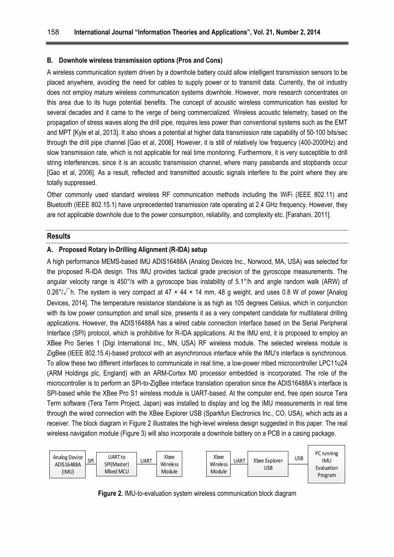
Devices, 2014]. The temperature resistance standalone is as high as 105 degrees Celsius, which in conjunction with its low power consumption and small size, presents it as a very competent candidate for multilateral drilling applications. However, the ADIS16488A has a wired cable connection interface based on the Serial Peripheral Interface (SPI) protocol, which is prohibitive for R-IDA applications. At the IMU end, it is proposed to employ an XBee Pro Series 1 (Digi International Inc., MN, USA) RF wireless module. The selected wireless module is ZigBee (IEEE 802.15.4)-based protocol with an asynchronous interface while the IMU’s interface is synchronous. To allow these two different interfaces to communicate in real time, a low-power mbed microcontroller LPC11u24 (ARM Holdings plc, England) with an ARM-Cortex M0 processor embedded is incorporated. The role of the microcontroller is to perform an SPI-to-ZigBee interface translation operation since the ADIS16488A’s interface is SPI-based while the XBee Pro S1 wireless module is UART-based. At the computer end, free open source Tera Term software (Tera Term Project, Japan) was installed to display and log the IMU measurements in real time through the wired connection with the XBee Explorer USB (Sparkfun Electronics Inc., CO, USA), which acts as a receiver. The block diagram in Figure 2 illustrates the high-level wireless design suggested in this paper. The real wireless navigation module (Figure 3) will also incorporate a downhole battery on a PCB in a casing package.
Figure 2. IMU-to-evaluation system wireless communication block diagram
Analog DeviceADIS16488A
(IMU)
UART to SPI(Master)Mbed MCU
Xbee Wireless Module
Xbee Explorer USB
SPI UART USBXbeeWireless Module
UARTPC running
IMU Evaluation Program
International Journal “Information Theories and Applications”, Vol. 21, Number 2, 2014
159
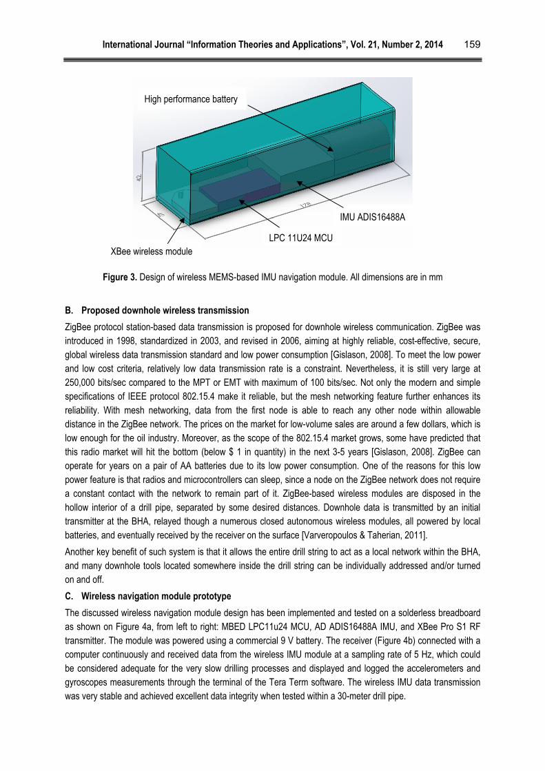
Figure 3. Design of wireless MEMS-based IMU navigation module. All dimensions are in mm
B. Proposed downhole wireless transmission
ZigBee protocol station-based data transmission is proposed for downhole wireless communication. ZigBee was introduced in 1998, standardized in 2003, and revised in 2006, aiming at highly reliable, cost-effective, secure, global wireless data transmission standard and low power consumption [Gislason, 2008]. To meet the low power and low cost criteria, relatively low data transmission rate is a constraint. Nevertheless, it is still very large at 250,000 bits/sec compared to the MPT or EMT with maximum of 100 bits/sec. Not only the modern and simple specifications of IEEE protocol 802.15.4 make it reliable, but the mesh networking feature further enhances its reliability. With mesh networking, data from the first node is able to reach any other node within allowable distance in the ZigBee network. The prices on the market for low-volume sales are around a few dollars, which is low enough for the oil industry. Moreover, as the scope of the 802.15.4 market grows, some have predicted that this radio market will hit the bottom (below $ 1 in quantity) in the next 3-5 years [Gislason, 2008]. ZigBee can operate for years on a pair of AA batteries due to its low power consumption. One of the reasons for this low power feature is that radios and microcontrollers can sleep, since a node on the ZigBee network does not require a constant contact with the network to remain part of it. ZigBee-based wireless modules are disposed in the hollow interior of a drill pipe, separated by some desired distances. Downhole data is transmitted by an initial transmitter at the BHA, relayed though a numerous closed autonomous wireless modules, all powered by local batteries, and eventually received by the receiver on the surface [Varveropoulos & Taherian, 2011].
Another key benefit of such system is that it allows the entire drill string to act as a local network within the BHA, and many downhole tools located somewhere inside the drill string can be individually addressed and/or turned on and off.
C. Wireless navigation module prototype
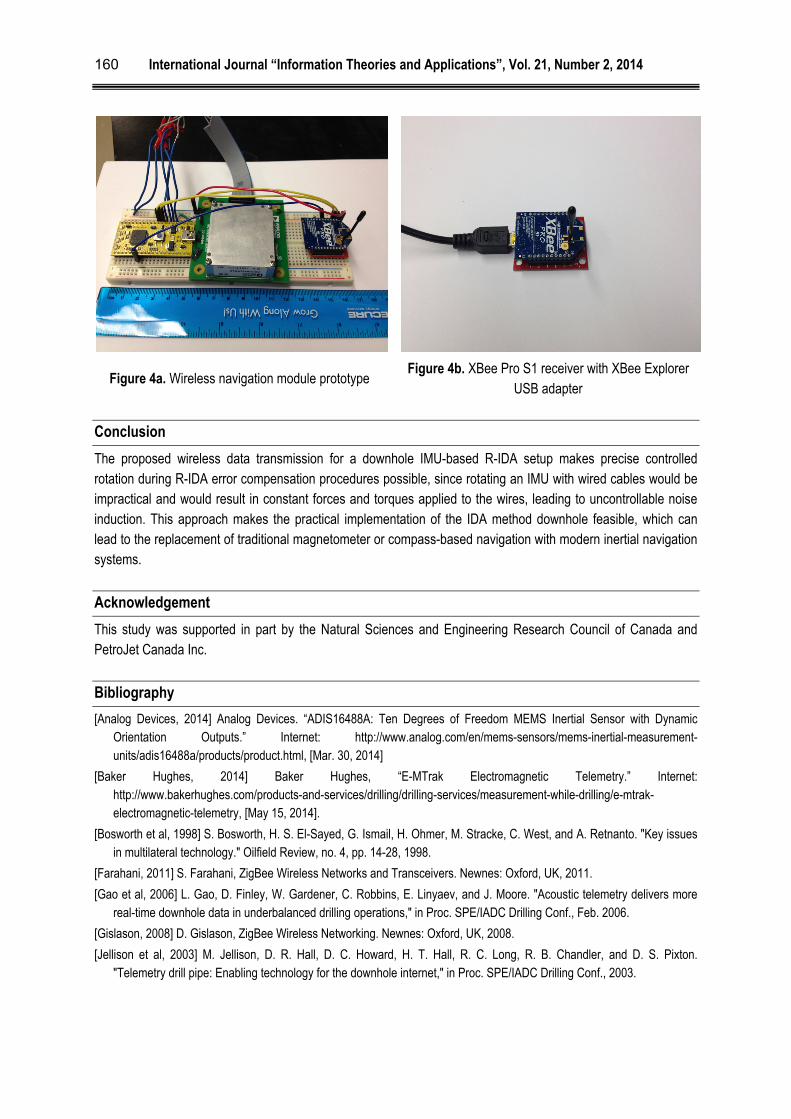
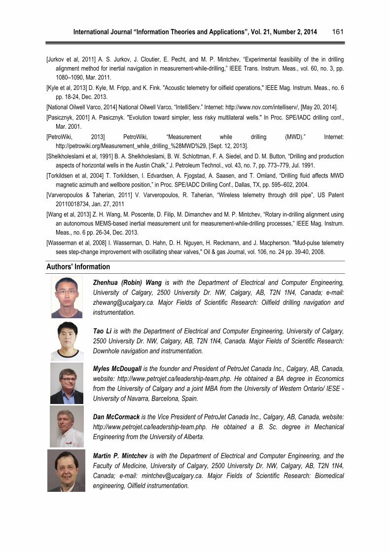
The discussed wireless navigation module design has been implemented and tested on a solderless breadboard as shown on Figure 4a, from left to right: MBED LPC11u24 MCU, AD ADIS16488A IMU, and XBee Pro S1 RF transmitter. The module was powered using a commercial 9 V battery. The receiver (Figure 4b) connected with a computer continuously and received data from the wireless IMU module at a sampling rate of 5 Hz, which could be considered adequate for the very slow drilling processes and displayed and logged the accelerometers and gyroscopes measurements through the terminal of the Tera Term software. The wireless IMU data transmission was very stable and achieved excellent data integrity when tested within a 30-meter drill pipe.
XBee wireless module LPC 11U24 MCU
IMU ADIS16488A
High performance battery
International Journal “Information Theories and Applications”, Vol. 21, Number 2, 2014
160
Figure 4a. Wireless navigation module prototype Figure 4b. XBee Pro S1 receiver with XBee Explorer
USB adapter
Conclusion
The proposed wireless data transmission for a downhole IMU-based R-IDA setup makes precise controlled rotation during R-IDA error compensation procedures possible, since rotating an IMU with wired cables would be impractical and would result in constant forces and torques applied to the wires, leading to uncontrollable noise induction. This approach makes the practical implementation of the IDA method downhole feasible, which can lead to the replacement of traditional magnetometer or compass-based navigation with modern inertial navigation systems.
Acknowledgement
This study was supported in part by the Natural Sciences and Engineering Research Council of Canada and PetroJet Canada Inc.
Bibliography
[Analog Devices, 2014] Analog Devices. “ADIS16488A: Ten Degrees of Freedom MEMS Inertial Sensor with Dynamic Orientation Outputs.” Internet: http://www.analog.com/en/mems-sensors/mems-inertial-measurement-units/adis16488a/products/product.html, [Mar. 30, 2014]
[Baker Hughes, 2014] Baker Hughes, “E-MTrak Electromagnetic Telemetry.” Internet: http://www.bakerhughes.com/products-and-services/drilling/drilling-services/measurement-while-drilling/e-mtrak-electromagnetic-telemetry, [May 15, 2014].
[Bosworth et al, 1998] S. Bosworth, H. S. El-Sayed, G. Ismail, H. Ohmer, M. Stracke, C. West, and A. Retnanto. "Key issues in multilateral technology." Oilfield Review, no. 4, pp. 14-28, 1998.
[Farahani, 2011] S. Farahani, ZigBee Wireless Networks and Transceivers. Newnes: Oxford, UK, 2011.
[Gao et al, 2006] L. Gao, D. Finley, W. Gardener, C. Robbins, E. Linyaev, and J. Moore. "Acoustic telemetry delivers more real-time downhole data in underbalanced drilling operations," in Proc. SPE/IADC Drilling Conf., Feb. 2006.
[Gislason, 2008] D. Gislason, ZigBee Wireless Networking. Newnes: Oxford, UK, 2008.
[Jellison et al, 2003] M. Jellison, D. R. Hall, D. C. Howard, H. T. Hall, R. C. Long, R. B. Chandler, and D. S. Pixton. "Telemetry drill pipe: Enabling technology for the downhole internet," in Proc. SPE/IADC Drilling Conf., 2003.
International Journal “Information Theories and Applications”, Vol. 21, Number 2, 2014
161
[Jurkov et al, 2011] A. S. Jurkov, J. Cloutier, E. Pecht, and M. P. Mintchev, “Experimental feasibility of the in drilling alignment method for inertial navigation in measurement-while-drilling,” IEEE Trans. Instrum. Meas., vol. 60, no. 3, pp. 1080–1090, Mar. 2011.
[Kyle et al, 2013] D. Kyle, M. Fripp, and K. Fink. "Acoustic telemetry for oilfield operations," IEEE Mag. Instrum. Meas., no. 6 pp. 18-24, Dec. 2013.
[National Oilwell Varco, 2014] National Oilwell Varco, “IntelliServ.” Internet: http://www.nov.com/intelliserv/, [May 20, 2014].
[Pasicznyk, 2001] A. Pasicznyk. "Evolution toward simpler, less risky multilateral wells." In Proc. SPE/IADC drilling conf., Mar. 2001.
[PetroWiki, 2013] PetroWiki, “Measurement while drilling (MWD).” Internet: http://petrowiki.org/Measurement_while_drilling_%28MWD%29, [Sept. 12, 2013].
[Shelkholeslami et al, 1991] B. A. Shelkholeslami, B. W. Schlottman, F. A. Siedel, and D. M. Button, “Drilling and production aspects of horizontal wells in the Austin Chalk,” J. Petroleum Technol., vol. 43, no. 7, pp. 773–779, Jul. 1991.
[Torkildsen et al, 2004] T. Torkildsen, I. Edvardsen, A. Fjogstad, A. Saasen, and T. Omland, “Drilling fluid affects MWD magnetic azimuth and wellbore position,” in Proc. SPE/IADC Drilling Conf., Dallas, TX, pp. 595–602, 2004.
[Varveropoulos & Taherian, 2011] V. Varveropoulos, R. Taherian, “Wireless telemetry through drill pipe”, US Patent 20110018734, Jan. 27, 2011
[Wang et al, 2013] Z. H. Wang, M. Poscente, D. Filip, M. Dimanchev and M. P. Mintchev, “Rotary in-drilling alignment using an autonomous MEMS-based inertial measurement unit for measurement-while-drilling processes,” IEEE Mag. Instrum. Meas., no. 6 pp. 26-34, Dec. 2013.
[Wasserman et al, 2008] I. Wasserman, D. Hahn, D. H. Nguyen, H. Reckmann, and J. Macpherson. "Mud-pulse telemetry sees step-change improvement with oscillating shear valves," Oil & gas Journal, vol. 106, no. 24 pp. 39-40, 2008.
Authors' Information
Zhenhua (Robin) Wang is with the Department of Electrical and Computer Engineering, University of Calgary, 2500 University Dr. NW, Calgary, AB, T2N 1N4, Canada; e-mail: [email protected]. Major Fields of Scientific Research: Oilfield drilling navigation and instrumentation.
Tao Li is with the Department of Electrical and Computer Engineering, University of Calgary, 2500 University Dr. NW, Calgary, AB, T2N 1N4, Canada. Major Fields of Scientific Research: Downhole navigation and instrumentation.
Myles McDougall is the founder and President of PetroJet Canada Inc., Calgary, AB, Canada, website: http://www.petrojet.ca/leadership-team.php. He obtained a BA degree in Economics from the University of Calgary and a joint MBA from the University of Western Ontario/ IESE - University of Navarra, Barcelona, Spain.
Dan McCormack is the Vice President of PetroJet Canada Inc., Calgary, AB, Canada, website: http://www.petrojet.ca/leadership-team.php. He obtained a B. Sc. degree in Mechanical Engineering from the University of Alberta.
Martin P. Mintchev is with the Department of Electrical and Computer Engineering, and the Faculty of Medicine, University of Calgary, 2500 University Dr. NW, Calgary, AB, T2N 1N4, Canada; e-mail: [email protected]. Major Fields of Scientific Research: Biomedical engineering, Oilfield instrumentation.