Embed Size (px)
Citation preview
WWiirreelleessss 880022..1111gg//bb UUSSBB SSttiicckk
User Manual
Version 1.0
M101703V10 1
No part of this documentation may be reproduced in any form or by any means or used to make any derivative work (such as translation, transformation, or adaptation) without written permission from the copyright owner.
All the other trademarks and registered trademarks are the property of their respective owners.
Statement of Conditions
We may make improvements or changes in the product described in this documentation at any time. The information regarding to the product in this manual are subject to change without notice.
We assume no responsibility for errors contained herein or for direct, indirect, special, incidental, or consequential damages with the furnishing, performance, or use of this manual or equipment supplied with it, even if the suppliers have been advised of the possibility of such damages.
Electronic Emission Notices
This device complies with Part 15 of the FCC Rules. Operation is subject to the following two conditions:
(1) This device may not cause harmful interference.
(2) This device must accept any interference received, including interference that may cause undesired operation.
FCC INFORMATION
The Federal Communication Commission Radio Frequency Interference Statement includes the following paragraph:
The equipment has been tested and found to comply with the limits for a Class B Digital Device, pursuant to part 15 of the FCC Rules. These limits are designed to provide reasonable protection against harmful interference in a residential installation. This equipment generates, uses and can radiate radio frequency energy and, if not installed and used in accordance with the instruction, may cause harmful interference to radio communication. However, there is no guarantee that interference will not occur in a particular installation. If this equipment does cause harmful interference to radio or television reception, which can be determined by turning the equipment off and on, the user is encouraged to try to overcome the interference by one or more of the following measures:
--Reorient or relocate the receiving antenna.
--Increase the separation between the equipment and receiver.
--Connect the equipment into an outlet on a circuit different from that to which the receiver is connected.
--Consult the dealer or an experienced radio/TV technician for help.
The equipment is for home or office use.
R&TTE Compliance Statement
This equipment complies with all the requirements of the Directive 1999/5/EC of the European parliament and the council of 9 March 1999 on radio equipment and telecommunication terminal Equipment and the mutual recognition of their conformity(R&TTE).
The R&TTE Directive repeals and replaces in the directive 98/13/EEC. As of April 8, 2000.
IMPORTANT NOTE
FCC RF Radiation Exposure Statement: This equipment complies with FCC RF radiation exposure limits set forth
for an uncontrolled environment. This device has been tested for compliance with FCC RF Exposure (SAR)

M101703V10 2
limits in typical laptop configurations and This Transmitter must not be co-located or operating in conjunction
with any other antenna or transmitter.
Caution: Changes or modifications not expressly approved by the party responsible for compliance could void the user's authority to operate the equipment.
TTaabbllee ooff CCoonntteennttss
INTRODUCTION.................................................................................................................................................2
1.1 Features.......................................................................................................................................... 2 1.2 Package Contents .......................................................................................................................... 2 1.3 System Requirements .................................................................................................................... 3 1.4 Your Wireless 802.11g/b USB Stick ............................................................................................... 3
INSTALLATION OF THE WIRELESS 802.11g/b USB STICK ......................................................................4
2.1 Installation Procedures................................................................................................................... 4 2.2 Installation Notes - Windows XP.................................................................................................... 7 2.3 Verifying a Successful Installation.................................................................................................. 9
CONFIGURATION FOR WINDOWS XP .......................................................................................................10
3.1 To Connect an Available Network via Wireless Zero Configuration ............................................ 10 3.2 To Configure the Wireless Networks Properties ...........................................................................11 3.3 To Access to Certain Wireless Network Type .............................................................................. 14
WIRELESS-G CONFIGURATION TOOL BASICS.......................................................................................15
4.1 Tray Icon ....................................................................................................................................... 15 4.2 Right-Click Menu of the Tray Icon................................................................................................ 15
Wireless Radio On ........................................................................................................................................16 Wireless Radio Off ........................................................................................................................................16 Remove Status Icon.......................................................................................................................................16 Wireless Network Status................................................................................................................................16 Advanced Configuration...............................................................................................................................17 WEP Encryption ...........................................................................................................................................17 IBSS Channel................................................................................................................................................17 Country/Domain ...........................................................................................................................................17 Version Information ......................................................................................................................................17
4.3 Program Controls ......................................................................................................................... 17 The Status Tab...............................................................................................................................................18
State ..........................................................................................................................................................19 Current Tx Rate ........................................................................................................................................19 Current Channel .......................................................................................................................................19 Throughout (bytes/sec).............................................................................................................................19 Link Quality .............................................................................................................................................19 Signal Strength .........................................................................................................................................20
M101703V10 1
The Configuration Tab..................................................................................................................................20 Profile Name ............................................................................................................................................20 Network Name .........................................................................................................................................21 Network Type ...........................................................................................................................................21 Peer-to-Peer Channel................................................................................................................................21 Transmit Rate ...........................................................................................................................................21
The Encryption Tab.......................................................................................................................................22 Encryption (WEP security).......................................................................................................................22 Create Keys Manually ..............................................................................................................................22 Use WEP Key...........................................................................................................................................23 Create Keys with Passphrase....................................................................................................................23
The Site Survey Tab.......................................................................................................................................23 The IBSS Tab.................................................................................................................................................24 The Domain Tab............................................................................................................................................24
802.11d Support .......................................................................................................................................25 Countries/Domains...................................................................................................................................25
The About Tab...............................................................................................................................................26 Network Driver ........................................................................................................................................26 Configuration Utility ................................................................................................................................26 NIC Firmware ..........................................................................................................................................26
4.4 The Advanced Properties Tab ...................................................................................................... 26 Configuration Profile................................................................................................................................28 Fragmentation Threshold .........................................................................................................................28 Niro Mode ................................................................................................................................................28 Power Save Mode.....................................................................................................................................28 RTS Threshold..........................................................................................................................................29 The Long/Short Retry Limit.....................................................................................................................29
APPENDIX A: TROUBLESHOOTING ...........................................................................................................30
Uninstall WirelessLAN-G Configuration Tool and the Stick’s Driver .................................................. 30 The Wireless 802.11g/b USB Stick Does Not Work Properly ............................................................ 31 Upgrade WLAN-G Configuration Tool and the Stick’s Driver............................................................. 32
APPENDIX B: SPECIFICATIONS...................................................................................................................36
APPENDIX C: GLOSSARY ..............................................................................................................................38
LLiisstt ooff FFiigguurreess FIGURE 1.4-1: WIRELESS 802.11g/b USB STICK.....................................................................................................3 FIGURE 1.4-2: ROTATE THE USB CONNECTOR........................................................................................................3 FIGURE 2.1-1: THE FOUND NEW HARDWARE WIZARD DIALOG BOX...................................................................4 FIGURE 2.1-2: THE STARTUP WINDOW....................................................................................................................5 FIGURE 2.1-3: THE 11MBPS WIRELESS LAN WINDOW.........................................................................................5 FIGURE 2.1-4: THE HARDWARE INSTALLATION DIALOG BOX ..............................................................................6 FIGURE 2.1-5: THE REBOOT SCREEN......................................................................................................................6 FIGURE 2.2-1: THE WIRELESS-G CONFIGURATION TOOL TRAY ICON.................................................................7 FIGURE 2.2-2: THE WIRELESS SETTINGS DIALOG BOX.........................................................................................7 FIGURE 2.2-3: THE WIRELESS NETWORK CONNECTION STATUS DIALOG BOX ..................................................8 FIGURE 2.2-4: THE WIRELESS NETWORK CONNECTION PROPERTIES DIALOG BOX..........................................8 FIGURE 2.3-1: THE DEVICE MANAGER DIALOG BOX ............................................................................................9 FIGURE 3-1: THE WIRELESS NETWORK CONNECTION ICON..............................................................................10 FIGURE 3.1-1: THE CONNECT TO WIRELESS NETWORK DIALOG BOX ..............................................................10 FIGURE 3.2-1: THE CONNECT TO WIRELESS NETWORK DIALOG BOX ..............................................................11 FIGURE 3.2-2: THE WIRELESS NETWORK CONNECTION PROPERTIES DIALOG BOX........................................11 FIGURE 3.2-3: THE WIRELESS NETWORK PROPERTIES DIALOG BOX ...............................................................12 FIGURE 3.2-4: ENTER WEP ...................................................................................................................................13 FIGURE 3.2-5: SETTING UP WIRELESS NETWORK CONFIGURATION .......................................................................13 FIGURE 3.3-1 THE ADVANCED DIALOG BOX: .......................................................................................................14 FIGURE 4.2-1: RIGHT-CLICK MENU OF THE TRAY ICON........................................................................................16 FIGURE 4.2-2: THE REMOVE WIRELESS STATUS ICON DIALOG BOX .................................................................16 FIGURE 4.3-1: THE WIRELESS SETTINGS DIALOG BOX.......................................................................................18 FIGURE 4.3-2: THE STATUS TAB............................................................................................................................18 FIGURE 4.3-3: THE CONFIGURATION TAB............................................................................................................20 FIGURE 4.3-4: THE ENCRYPTION TAB ..................................................................................................................22 FIGURE 4.3-5: THE SITE SURVEY TAB ..................................................................................................................23 FIGURE 4.3-6: THE IBSS TAB................................................................................................................................24 FIGURE 4.3-7: THE DOMAIN TAB ..........................................................................................................................25 FIGURE 4.3-8: THE ABOUT TAB ............................................................................................................................26 FIGURE 4.4-1: THE DEVICE MANAGER DIALOG BOX ..........................................................................................27 FIGURE 4.4-2: THE ADVANCED TAB......................................................................................................................27 FIGURE 5-1: THE DEVICE MANAGER DIALOG BOX.............................................................................................30 FIGURE 5-2: THE CONFIRM DEVICE REMOVAL MESSAGE BOX..........................................................................31 FIGURE 5-3: THE ADD OR REMOVE PROGRAMS DIALOG BOX ...........................................................................31 FIGURE 5-4: THE DEVICE MANAGER DIALOG BOX.............................................................................................32

M101703V10 1
FIGURE 5-5: THE HARDWARE UPDATE WIZARD DIALOG BOX ...........................................................................33 FIGURE 5-6: CHOOSE THE FOLDER NAMED INSTALL ...........................................................................................33 FIGURE 5-7: THE HARDWARE INSTALLATION DIALOG BOX ...............................................................................34 FIGURE 5-8: INSTALLING THE SOFTWARE..............................................................................................................34 FIGURE 5-9: THE COMPLETE SCREEN..................................................................................................................35
M101703V10 2
INTRODUCTION
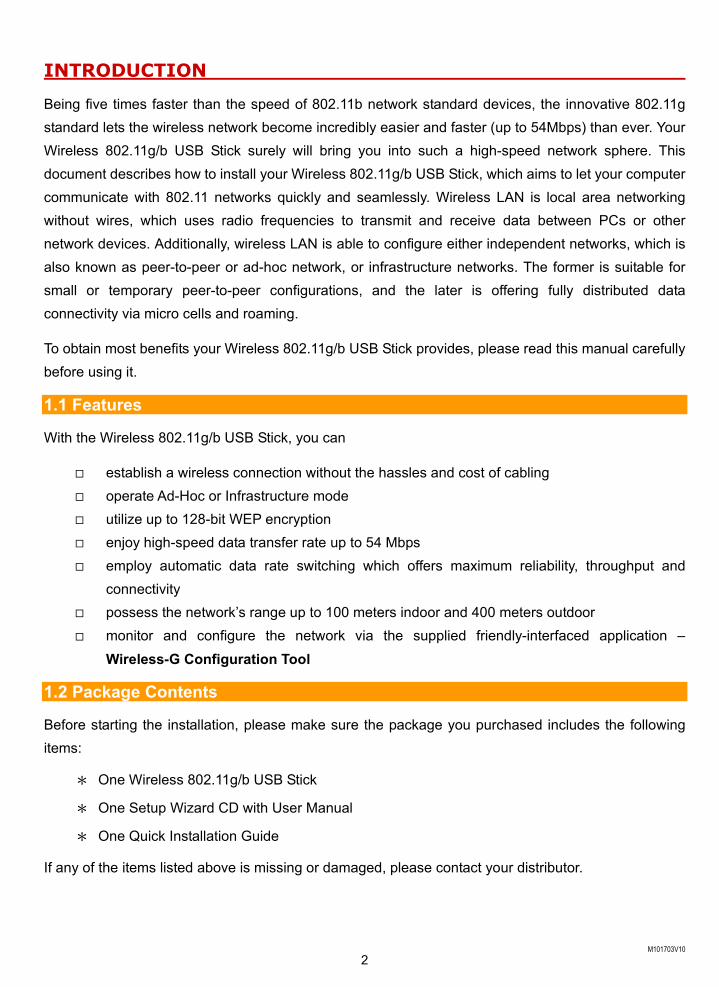
Being five times faster than the speed of 802.11b network standard devices, the innovative 802.11g standard lets the wireless network become incredibly easier and faster (up to 54Mbps) than ever. Your Wireless 802.11g/b USB Stick surely will bring you into such a high-speed network sphere. This document describes how to install your Wireless 802.11g/b USB Stick, which aims to let your computer communicate with 802.11 networks quickly and seamlessly. Wireless LAN is local area networking without wires, which uses radio frequencies to transmit and receive data between PCs or other network devices. Additionally, wireless LAN is able to configure either independent networks, which is also known as peer-to-peer or ad-hoc network, or infrastructure networks. The former is suitable for small or temporary peer-to-peer configurations, and the later is offering fully distributed data connectivity via micro cells and roaming.
To obtain most benefits your Wireless 802.11g/b USB Stick provides, please read this manual carefully before using it.
1.1 Features
With the Wireless 802.11g/b USB Stick, you can
establish a wireless connection without the hassles and cost of cabling operate Ad-Hoc or Infrastructure mode utilize up to 128-bit WEP encryption enjoy high-speed data transfer rate up to 54 Mbps employ automatic data rate switching which offers maximum reliability, throughput and
connectivity possess the network’s range up to 100 meters indoor and 400 meters outdoor
monitor and configure the network via the supplied friendly-interfaced application – Wireless-G Configuration Tool
1.2 Package Contents
Before starting the installation, please make sure the package you purchased includes the following items:
* One Wireless 802.11g/b USB Stick
* One Setup Wizard CD with User Manual
* One Quick Installation Guide
If any of the items listed above is missing or damaged, please contact your distributor.
M101703V10 3
1.3 System Requirements To properly operate your Wireless 802.11g/b USB Stick, your computer must meet the following minimum requirements:
* 32 MB RAM or above
* A CD-ROM drive
* 300 MHz processor or higher
* Microsoft Windows 2000 or Windows XP
* USB Port version 2.0
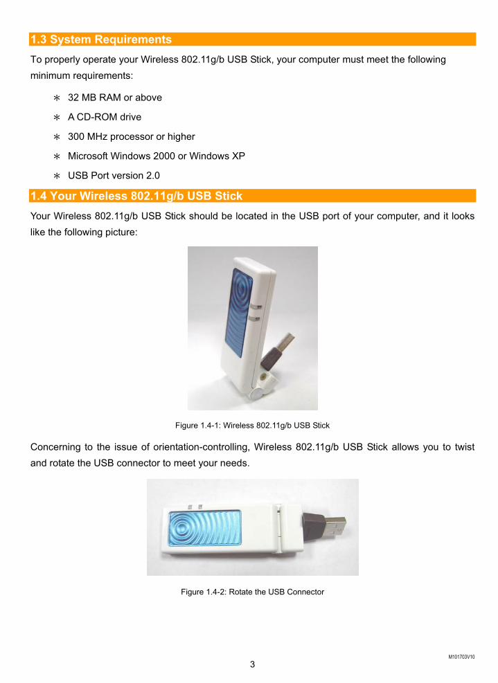
1.4 Your Wireless 802.11g/b USB Stick Your Wireless 802.11g/b USB Stick should be located in the USB port of your computer, and it looks like the following picture:
Figure 1.4-1: Wireless 802.11g/b USB Stick
Concerning to the issue of orientation-controlling, Wireless 802.11g/b USB Stick allows you to twist and rotate the USB connector to meet your needs.
Figure 1.4-2: Rotate the USB Connector
M101703V10 4
INSTALLATION OF THE WIRELESS 802.11g/b USB STICK
It’s free and easy for you to install your Wireless 802.11g/b USB Stick and the attached software – Wireless-G Configuration Tool. Simply with a few clicks of the mouse, you will succeed the completion of installation.
2.1 Installation Procedures
To have the Wireless 802.11g/b USB Stick operated appropriately, please read and go along with the instructions below carefully. Here we take Windows XP as an example.
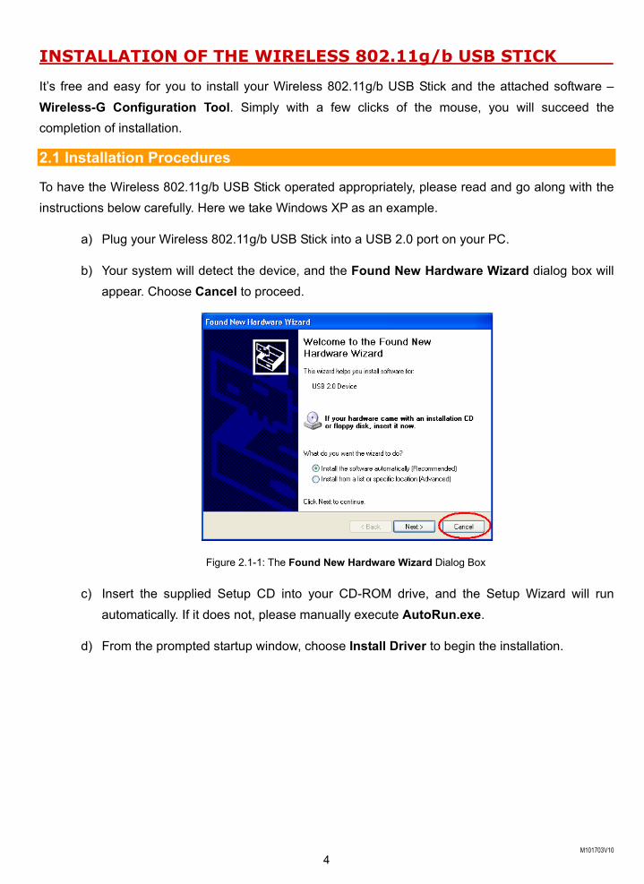
a) Plug your Wireless 802.11g/b USB Stick into a USB 2.0 port on your PC.
b) Your system will detect the device, and the Found New Hardware Wizard dialog box will appear. Choose Cancel to proceed.
Figure 2.1-1: The Found New Hardware Wizard Dialog Box
c) Insert the supplied Setup CD into your CD-ROM drive, and the Setup Wizard will run automatically. If it does not, please manually execute AutoRun.exe.
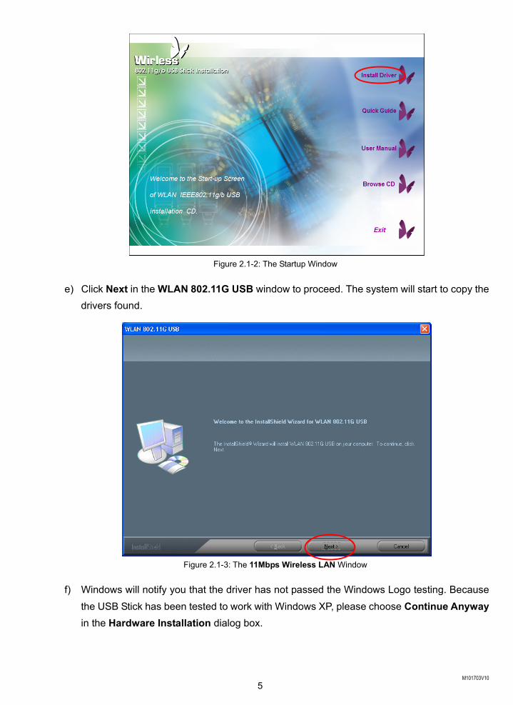
d) From the prompted startup window, choose Install Driver to begin the installation.
M101703V10 5
Figure 2.1-2: The Startup Window
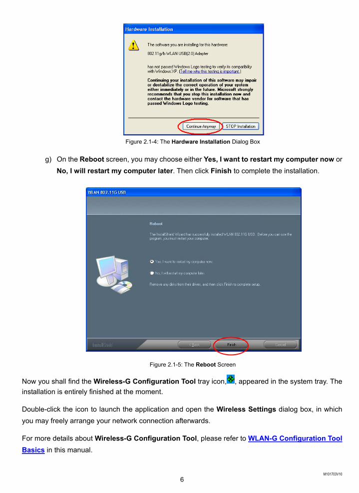
e) Click Next in the WLAN 802.11G USB window to proceed. The system will start to copy the drivers found.
Figure 2.1-3: The 11Mbps Wireless LAN Window
f) Windows will notify you that the driver has not passed the Windows Logo testing. Because the USB Stick has been tested to work with Windows XP, please choose Continue Anyway in the Hardware Installation dialog box.
M101703V10 6
Figure 2.1-4: The Hardware Installation Dialog Box
g) On the Reboot screen, you may choose either Yes, I want to restart my computer now or No, I will restart my computer later. Then click Finish to complete the installation.
Figure 2.1-5: The Reboot Screen
Now you shall find the Wireless-G Configuration Tool tray icon, , appeared in the system tray. The installation is entirely finished at the moment.
Double-click the icon to launch the application and open the Wireless Settings dialog box, in which you may freely arrange your network connection afterwards.
For more details about Wireless-G Configuration Tool, please refer to WLAN-G Configuration Tool Basics in this manual.
M101703V10 7
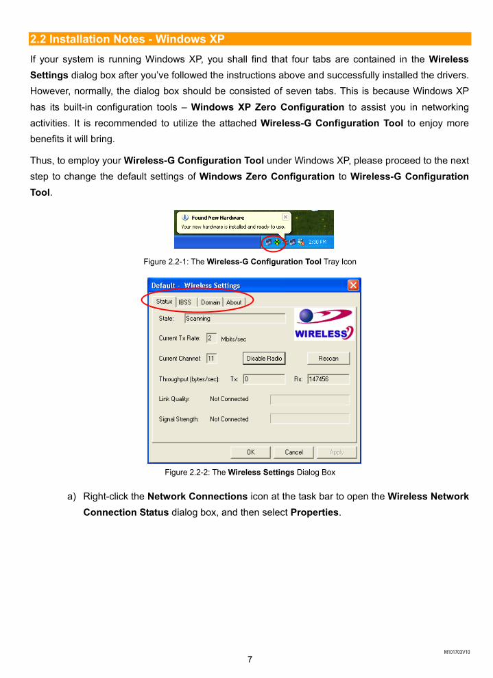
2.2 Installation Notes - Windows XP If your system is running Windows XP, you shall find that four tabs are contained in the Wireless Settings dialog box after you’ve followed the instructions above and successfully installed the drivers. However, normally, the dialog box should be consisted of seven tabs. This is because Windows XP has its built-in configuration tools – Windows XP Zero Configuration to assist you in networking activities. It is recommended to utilize the attached Wireless-G Configuration Tool to enjoy more benefits it will bring.
Thus, to employ your Wireless-G Configuration Tool under Windows XP, please proceed to the next step to change the default settings of Windows Zero Configuration to Wireless-G Configuration Tool.
Figure 2.2-1: The Wireless-G Configuration Tool Tray Icon
Figure 2.2-2: The Wireless Settings Dialog Box
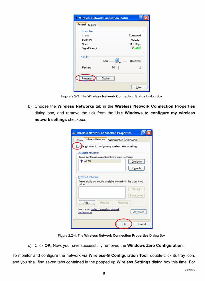
a) Right-click the Network Connections icon at the task bar to open the Wireless Network Connection Status dialog box, and then select Properties.
M101703V10 8
Figure 2.2-3: The Wireless Network Connection Status Dialog Box
b) Choose the Wireless Networks tab in the Wireless Network Connection Properties dialog box, and remove the tick from the Use Windows to configure my wireless network settings checkbox.
Figure 2.2-4: The Wireless Network Connection Properties Dialog Box
c) Click OK. Now, you have successfully removed the Windows Zero Configuration.
To monitor and configure the network via Wireless-G Configuration Tool, double-click its tray icon, and you shall find seven tabs contained in the popped up Wireless Settings dialog box this time. For
M101703V10 9
more information on Wireless-G Configuration Tool, please refer to the chapter: Wireless-G Configuration Tool Basics below.
Note: If you wish to use Windows XP’s built-in configuration tools – Windows XP Zero Configuration, please refer to the next chapter: Configuration for Windows XP to configure the WLAN USB Stick.
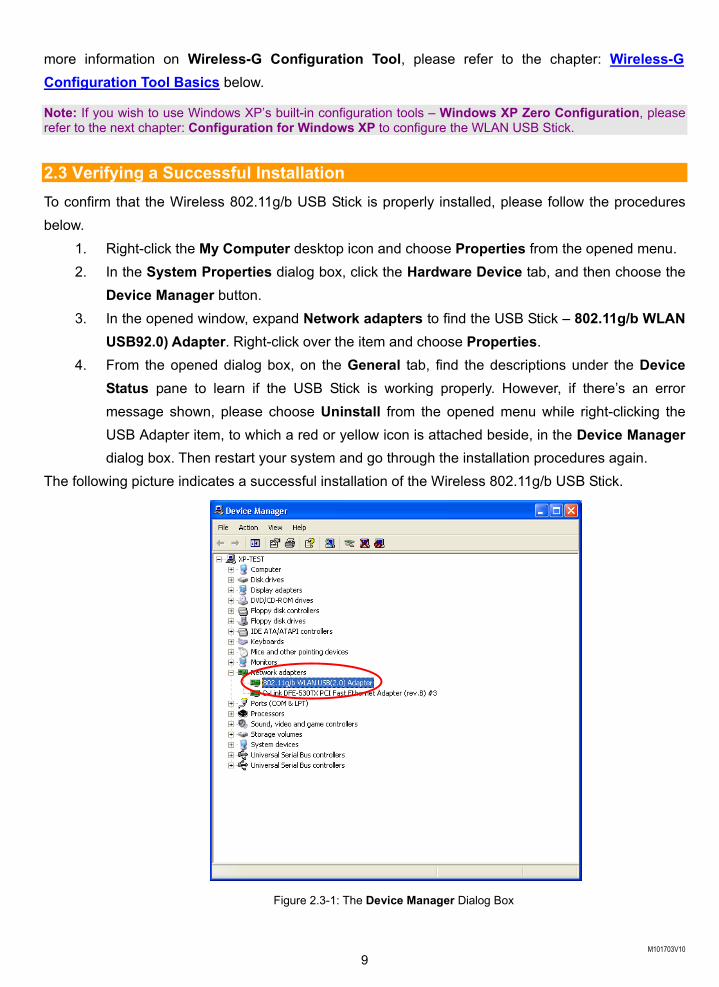
2.3 Verifying a Successful Installation To confirm that the Wireless 802.11g/b USB Stick is properly installed, please follow the procedures below.
1. Right-click the My Computer desktop icon and choose Properties from the opened menu. 2. In the System Properties dialog box, click the Hardware Device tab, and then choose the
Device Manager button. 3. In the opened window, expand Network adapters to find the USB Stick – 802.11g/b WLAN
USB92.0) Adapter. Right-click over the item and choose Properties. 4. From the opened dialog box, on the General tab, find the descriptions under the Device
Status pane to learn if the USB Stick is working properly. However, if there’s an error message shown, please choose Uninstall from the opened menu while right-clicking the USB Adapter item, to which a red or yellow icon is attached beside, in the Device Manager dialog box. Then restart your system and go through the installation procedures again.
The following picture indicates a successful installation of the Wireless 802.11g/b USB Stick.
Figure 2.3-1: The Device Manager Dialog Box
M101703V10 10
CONFIGURATION FOR WINDOWS XP
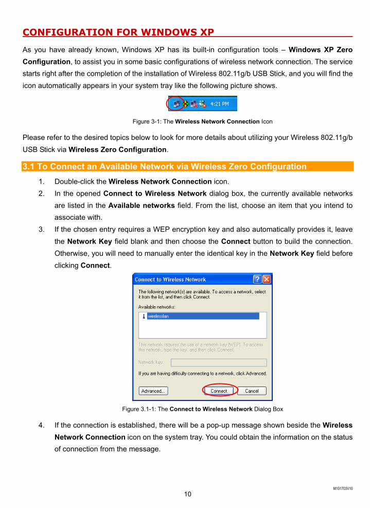
As you have already known, Windows XP has its built-in configuration tools – Windows XP Zero Configuration, to assist you in some basic configurations of wireless network connection. The service starts right after the completion of the installation of Wireless 802.11g/b USB Stick, and you will find the icon automatically appears in your system tray like the following picture shows.
Figure 3-1: The Wireless Network Connection Icon
Please refer to the desired topics below to look for more details about utilizing your Wireless 802.11g/b USB Stick via Wireless Zero Configuration.
3.1 To Connect an Available Network via Wireless Zero Configuration 1. Double-click the Wireless Network Connection icon. 2. In the opened Connect to Wireless Network dialog box, the currently available networks
are listed in the Available networks field. From the list, choose an item that you intend to associate with.
3. If the chosen entry requires a WEP encryption key and also automatically provides it, leave the Network Key field blank and then choose the Connect button to build the connection. Otherwise, you will need to manually enter the identical key in the Network Key field before clicking Connect.
Figure 3.1-1: The Connect to Wireless Network Dialog Box
4. If the connection is established, there will be a pop-up message shown beside the Wireless Network Connection icon on the system tray. You could obtain the information on the status of connection from the message.
M101703V10 11
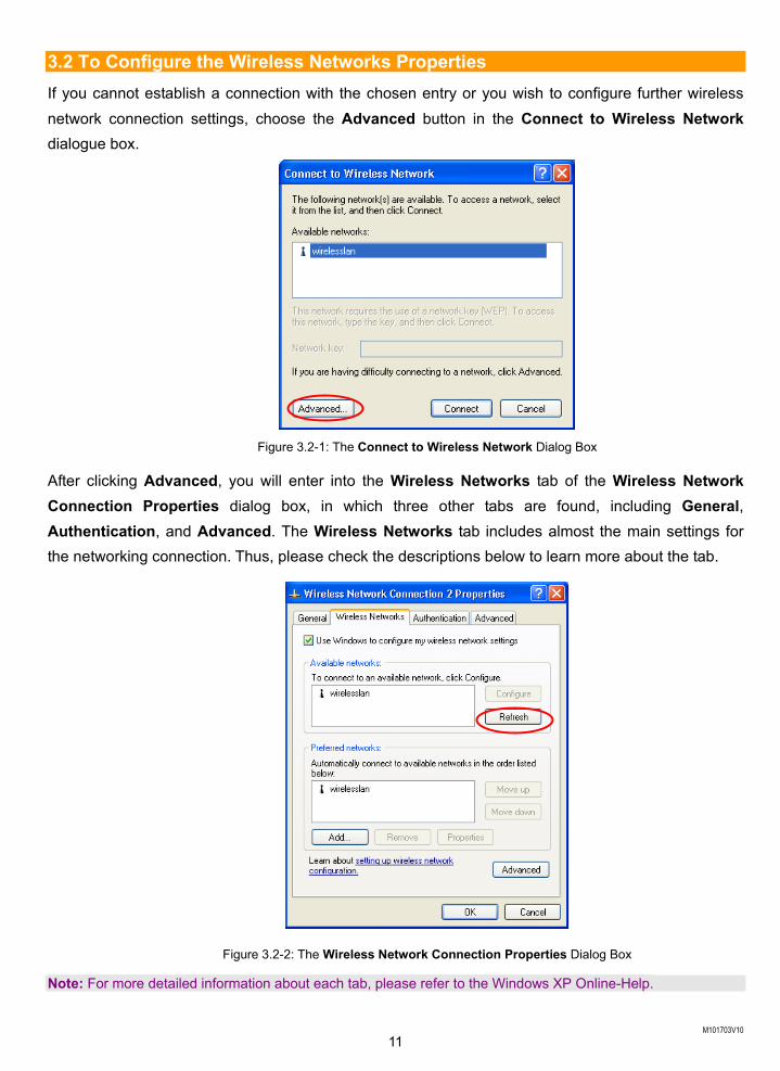
3.2 To Configure the Wireless Networks Properties If you cannot establish a connection with the chosen entry or you wish to configure further wireless network connection settings, choose the Advanced button in the Connect to Wireless Network dialogue box.
Figure 3.2-1: The Connect to Wireless Network Dialog Box
After clicking Advanced, you will enter into the Wireless Networks tab of the Wireless Network Connection Properties dialog box, in which three other tabs are found, including General, Authentication, and Advanced. The Wireless Networks tab includes almost the main settings for the networking connection. Thus, please check the descriptions below to learn more about the tab.
Figure 3.2-2: The Wireless Network Connection Properties Dialog Box
Note: For more detailed information about each tab, please refer to the Windows XP Online-Help.
M101703V10 12
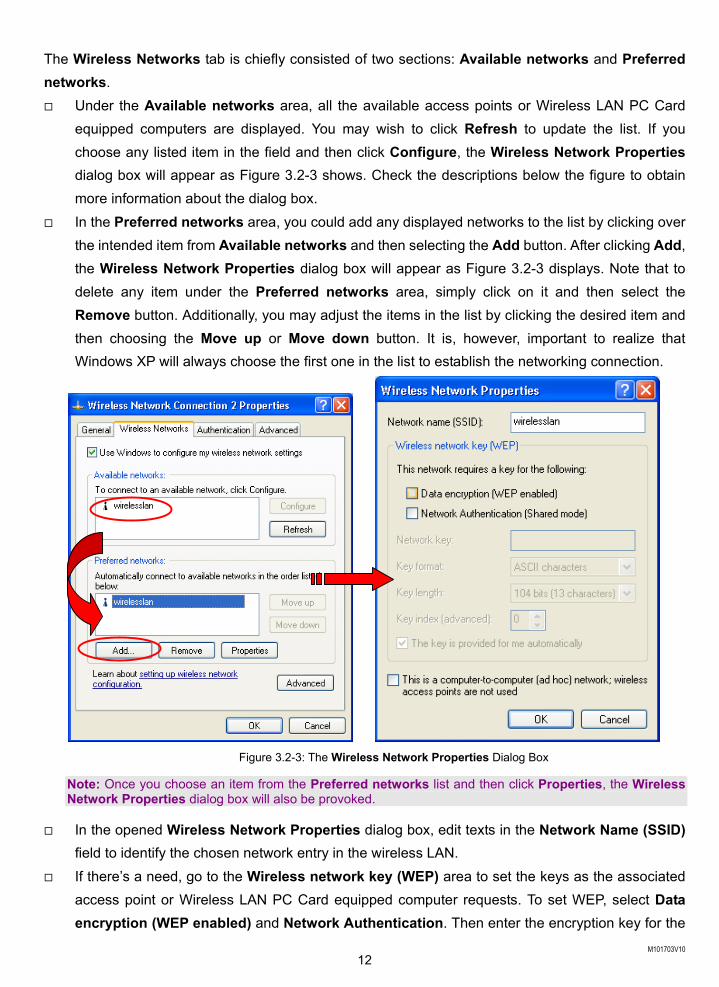
The Wireless Networks tab is chiefly consisted of two sections: Available networks and Preferred networks. Under the Available networks area, all the available access points or Wireless LAN PC Card
equipped computers are displayed. You may wish to click Refresh to update the list. If you choose any listed item in the field and then click Configure, the Wireless Network Properties dialog box will appear as Figure 3.2-3 shows. Check the descriptions below the figure to obtain more information about the dialog box.
In the Preferred networks area, you could add any displayed networks to the list by clicking over the intended item from Available networks and then selecting the Add button. After clicking Add, the Wireless Network Properties dialog box will appear as Figure 3.2-3 displays. Note that to delete any item under the Preferred networks area, simply click on it and then select the Remove button. Additionally, you may adjust the items in the list by clicking the desired item and then choosing the Move up or Move down button. It is, however, important to realize that Windows XP will always choose the first one in the list to establish the networking connection.
Figure 3.2-3: The Wireless Network Properties Dialog Box
Note: Once you choose an item from the Preferred networks list and then click Properties, the Wireless Network Properties dialog box will also be provoked.
In the opened Wireless Network Properties dialog box, edit texts in the Network Name (SSID) field to identify the chosen network entry in the wireless LAN.
If there’s a need, go to the Wireless network key (WEP) area to set the keys as the associated access point or Wireless LAN PC Card equipped computer requests. To set WEP, select Data encryption (WEP enabled) and Network Authentication. Then enter the encryption key for the
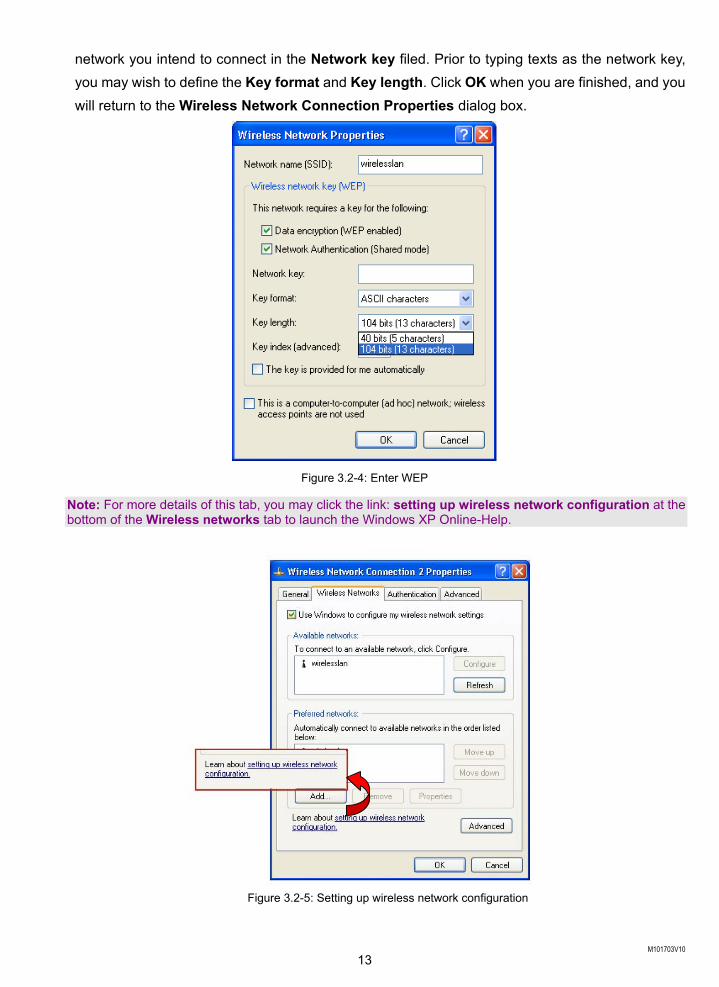
M101703V10 13
network you intend to connect in the Network key filed. Prior to typing texts as the network key, you may wish to define the Key format and Key length. Click OK when you are finished, and you will return to the Wireless Network Connection Properties dialog box.
Figure 3.2-4: Enter WEP
Note: For more details of this tab, you may click the link: setting up wireless network configuration at the bottom of the Wireless networks tab to launch the Windows XP Online-Help.
Figure 3.2-5: Setting up wireless network configuration
M101703V10 14
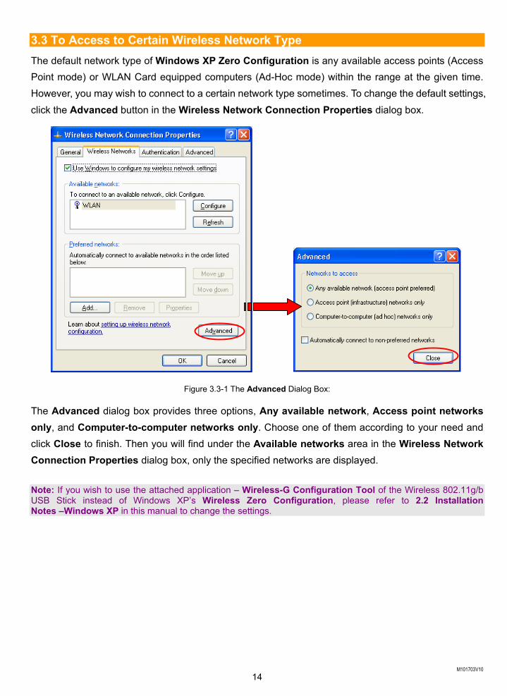
3.3 To Access to Certain Wireless Network Type The default network type of Windows XP Zero Configuration is any available access points (Access Point mode) or WLAN Card equipped computers (Ad-Hoc mode) within the range at the given time. However, you may wish to connect to a certain network type sometimes. To change the default settings, click the Advanced button in the Wireless Network Connection Properties dialog box.
Figure 3.3-1 The Advanced Dialog Box:
The Advanced dialog box provides three options, Any available network, Access point networks only, and Computer-to-computer networks only. Choose one of them according to your need and click Close to finish. Then you will find under the Available networks area in the Wireless Network Connection Properties dialog box, only the specified networks are displayed. Note: If you wish to use the attached application – Wireless-G Configuration Tool of the Wireless 802.11g/b USB Stick instead of Windows XP’s Wireless Zero Configuration, please refer to 2.2 Installation Notes –Windows XP in this manual to change the settings.
M101703V10 15
WIRELESS-G CONFIGURATION TOOL BASICS
After successfully installing the driver for your Wireless 802.11g/b USB Stick on your computer, you
may see the Wireless-G Configuration Tool icon, , displayed in the system tray. To set configurations for your USB Stick, double-click the icon to open the Wireless Settings dialog box, in which seven tabs are contained, including Status, Configuration, Encryption, Site Survey, IBSS, Domain, and About. Each of them proffers different functions to assist you in configuring the connection to the networks. In this chapter, four topics are offered: Tray Icon, Right-Click Menu of the Tray Icon, Program Controls, and The Advanced Properties Tab. Please refer to the preferred topic to obtain more information and enjoy vast advantages Wireless-G Configuration Tool brings.
4.1 Tray Icon As long as you finish installing Wireless-G Configuration Tool on your computer system, you will see
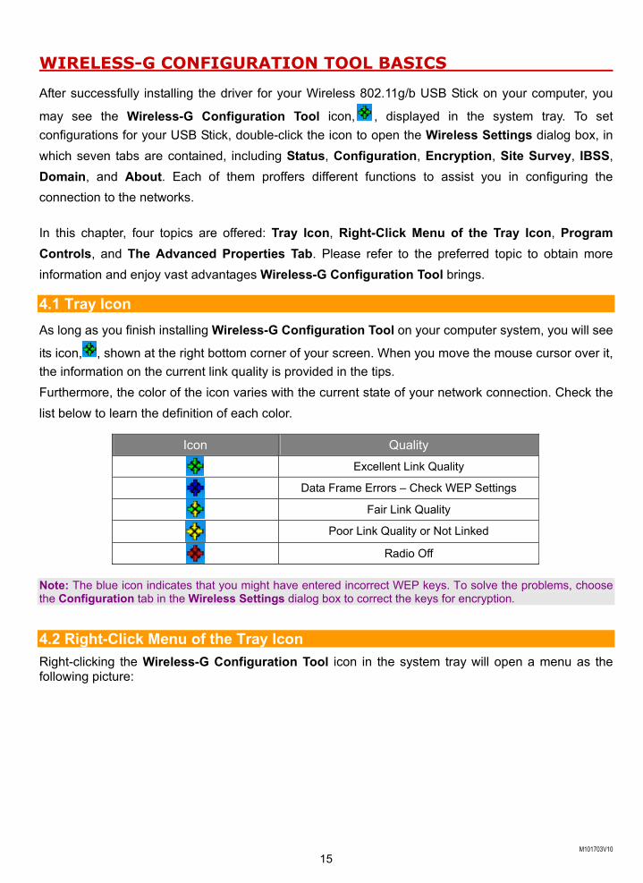
its icon, , shown at the right bottom corner of your screen. When you move the mouse cursor over it, the information on the current link quality is provided in the tips. Furthermore, the color of the icon varies with the current state of your network connection. Check the list below to learn the definition of each color.
Icon Quality
Excellent Link Quality
Data Frame Errors – Check WEP Settings
Fair Link Quality
Poor Link Quality or Not Linked
Radio Off
Note: The blue icon indicates that you might have entered incorrect WEP keys. To solve the problems, choose the Configuration tab in the Wireless Settings dialog box to correct the keys for encryption.
4.2 Right-Click Menu of the Tray Icon Right-clicking the Wireless-G Configuration Tool icon in the system tray will open a menu as the following picture:
M101703V10 16
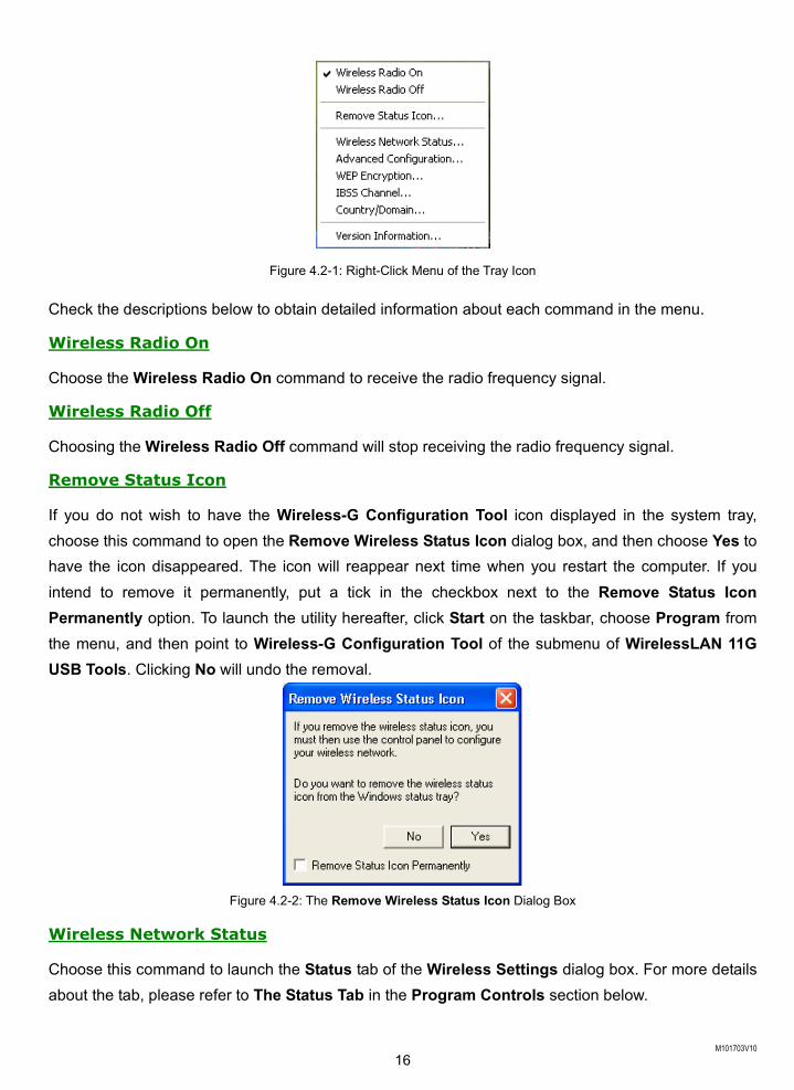
Figure 4.2-1: Right-Click Menu of the Tray Icon
Check the descriptions below to obtain detailed information about each command in the menu.
Wireless Radio On
Choose the Wireless Radio On command to receive the radio frequency signal.
Wireless Radio Off
Choosing the Wireless Radio Off command will stop receiving the radio frequency signal.
Remove Status Icon
If you do not wish to have the Wireless-G Configuration Tool icon displayed in the system tray, choose this command to open the Remove Wireless Status Icon dialog box, and then choose Yes to have the icon disappeared. The icon will reappear next time when you restart the computer. If you intend to remove it permanently, put a tick in the checkbox next to the Remove Status Icon Permanently option. To launch the utility hereafter, click Start on the taskbar, choose Program from the menu, and then point to Wireless-G Configuration Tool of the submenu of WirelessLAN 11G USB Tools. Clicking No will undo the removal.
Figure 4.2-2: The Remove Wireless Status Icon Dialog Box
Wireless Network Status
Choose this command to launch the Status tab of the Wireless Settings dialog box. For more details about the tab, please refer to The Status Tab in the Program Controls section below.
M101703V10 17
Advanced Configuration
Choose this command to launch the Configuration tab of the Wireless Settings dialog box. Please refer to The Configuration Tab in the Program Controls section below to gain more information about the tab.
WEP Encryption
Choose this command to launch the Encryption tab of the Wireless Settings dialog box. This tab offers you a number of options to maintain the secure management in a wireless LAN environment. See the explanations in The Encryption Tab under the Program Controls section below for more details.
IBSS Channel
Choosing this command will launch the IBSS tab of the Wireless Settings dialog box. To obtain more information about the tab, please refer to The IBSS Tab in the Program Controls section below.
Country/Domain
Choosing this command will launch the Domain tab of the Wireless Settings dialog box. Detailed information about this tab is presented in The Domain Tab of the Program Controls section.
Version Information
Choosing this command will launch the About tab of the Wireless Settings dialog box. The About tab reveals general information on your Wireless 802.11g/b USB Stick, including the release version of driver and the Wireless-G Configuration Tool and the USB network adapter’s MAC Address.
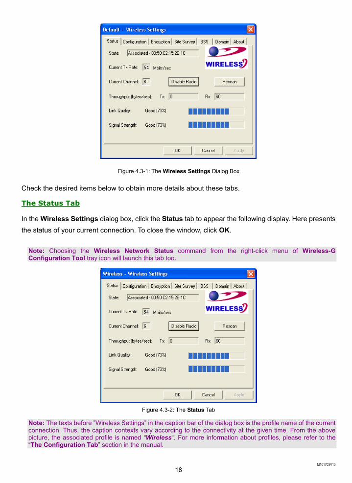
4.3 Program Controls When you double-click the Wireless-G Configuration Tool tray icon, the Wireless Settings dialog box will be prompted as the picture shows below. You may also launch this dialog box via clicking Start on the taskbar, choosing Program from the menu, and then pointing to Wireless-G Configuration Tool from the submenu of WLAN-G TOOLS.
The application is a window-based program, which is consisted of seven tabs, including Status, Configuration, Encryption, Site Survey, IBSS, Domain, and About. The following figure displays the Wireless Settings dialog box.
M101703V10 18
Figure 4.3-1: The Wireless Settings Dialog Box
Check the desired items below to obtain more details about these tabs.
The Status Tab
In the Wireless Settings dialog box, click the Status tab to appear the following display. Here presents the status of your current connection. To close the window, click OK.
Note: Choosing the Wireless Network Status command from the right-click menu of Wireless-G Configuration Tool tray icon will launch this tab too.
Figure 4.3-2: The Status Tab
Note: The texts before ”Wireless Settings” in the caption bar of the dialog box is the profile name of the current connection. Thus, the caption contexts vary according to the connectivity at the given time. From the above picture, the associated profile is named “Wireless”. For more information about profiles, please refer to the “The Configuration Tab” section in the manual.
M101703V10 19
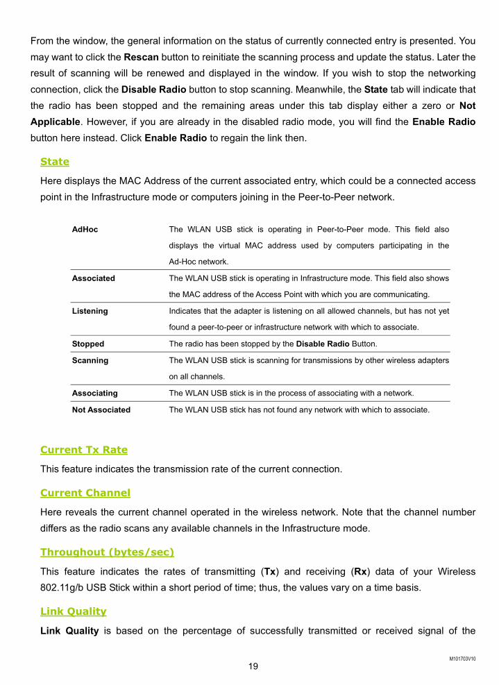
From the window, the general information on the status of currently connected entry is presented. You may want to click the Rescan button to reinitiate the scanning process and update the status. Later the result of scanning will be renewed and displayed in the window. If you wish to stop the networking connection, click the Disable Radio button to stop scanning. Meanwhile, the State tab will indicate that the radio has been stopped and the remaining areas under this tab display either a zero or Not Applicable. However, if you are already in the disabled radio mode, you will find the Enable Radio button here instead. Click Enable Radio to regain the link then.
State
Here displays the MAC Address of the current associated entry, which could be a connected access point in the Infrastructure mode or computers joining in the Peer-to-Peer network.
AdHoc The WLAN USB stick is operating in Peer-to-Peer mode. This field also
displays the virtual MAC address used by computers participating in the
Ad-Hoc network.
Associated The WLAN USB stick is operating in Infrastructure mode. This field also shows
the MAC address of the Access Point with which you are communicating. Listening Indicates that the adapter is listening on all allowed channels, but has not yet
found a peer-to-peer or infrastructure network with which to associate.
Stopped The radio has been stopped by the Disable Radio Button.
Scanning The WLAN USB stick is scanning for transmissions by other wireless adapters
on all channels.
Associating The WLAN USB stick is in the process of associating with a network.
Not Associated The WLAN USB stick has not found any network with which to associate.
Current Tx Rate
This feature indicates the transmission rate of the current connection.
Current Channel
Here reveals the current channel operated in the wireless network. Note that the channel number differs as the radio scans any available channels in the Infrastructure mode.
Throughout (bytes/sec)
This feature indicates the rates of transmitting (Tx) and receiving (Rx) data of your Wireless 802.11g/b USB Stick within a short period of time; thus, the values vary on a time basis.
Link Quality
Link Quality is based on the percentage of successfully transmitted or received signal of the
M101703V10 20
associated access point beacon within a limited period. The higher the percentage, the better the link quality. The bar graph beside also provides a visual interpretation of the current link quality. It is noted that the Link Quality and Signal Strength features only apply to the Infrastructure mode. They are inapplicable in the Ad-Hoc mode since data will be transferred from many different computers.
Signal Strength
You may learn the received signal strength of the baseband processor of the beacon signal from the Signal Strength bar beside, and it’s also presented in terms of percentage. As the signal gets stronger, the signal percentage rate gets higher. It is noted that the Signal Strength and Link Quality features only apply to the Infrastructure mode. They are inapplicable in the Ad-Hoc mode since data will be transferred from many different computers.
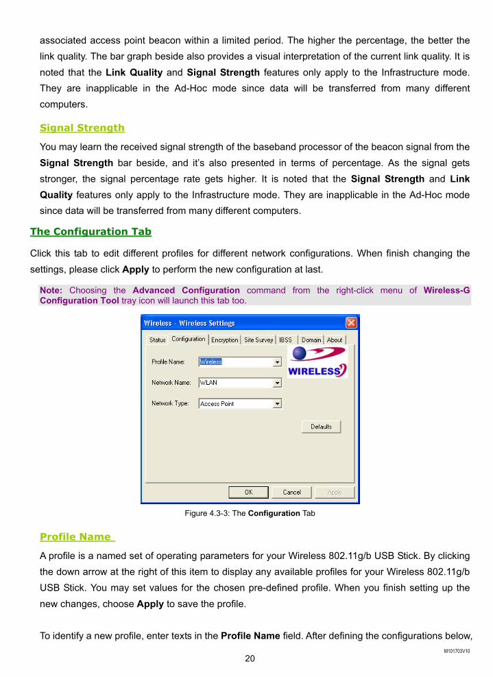
The Configuration Tab
Click this tab to edit different profiles for different network configurations. When finish changing the settings, please click Apply to perform the new configuration at last.
Note: Choosing the Advanced Configuration command from the right-click menu of Wireless-G Configuration Tool tray icon will launch this tab too.
Figure 4.3-3: The Configuration Tab
Profile Name
A profile is a named set of operating parameters for your Wireless 802.11g/b USB Stick. By clicking the down arrow at the right of this item to display any available profiles for your Wireless 802.11g/b USB Stick. You may set values for the chosen pre-defined profile. When you finish setting up the new changes, choose Apply to save the profile.
To identify a new profile, enter texts in the Profile Name field. After defining the configurations below,
M101703V10 21
click the Apply button to establish a new profile. To switch between any existing profiles, click the arrow button at the right of the Profile Name field to open the pull-down menu and then select an intended one from it.
Note: You will have at least one profile named Default. When selecting any link from the list under the Site Survey tab, you have already automatically established a new profile for it under the Configuration tab.
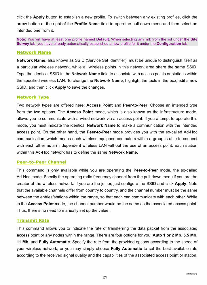
Network Name
Network Name, also known as SSID (Service Set Identifier), must be unique to distinguish itself as a particular wireless network, while all wireless points in this network area share the same SSID. Type the identical SSID in the Network Name field to associate with access points or stations within the specified wireless LAN. To change the Network Name, highlight the texts in the box, edit a new SSID, and then click Apply to save the changes.
Network Type
Two network types are offered here: Access Point and Peer-to-Peer. Choose an intended type from the two options. The Access Point mode, which is also known as the Infrastructure mode, allows you to communicate with a wired network via an access point. If you attempt to operate this mode, you must indicate the identical Network Name to make a communication with the intended access point. On the other hand, the Peer-to-Peer mode provides you with the so-called Ad-Hoc communication, which means each wireless-equipped computers within a group is able to connect with each other as an independent wireless LAN without the use of an access point. Each station within this Ad-Hoc network has to define the same Network Name.
Peer-to-Peer Channel
This command is only available while you are operating the Peer-to-Peer mode, the so-called Ad-Hoc mode. Specify the operating radio frequency channel from the pull-down menu if you are the creator of the wireless network. If you are the joiner, just configure the SSID and click Apply. Note that the available channels differ from country to country, and the channel number must be the same between the entries/stations within the range, so that each can communicate with each other. While in the Access Point mode, the channel number would be the same as the associated access point. Thus, there’s no need to manually set up the value.
Transmit Rate
This command allows you to indicate the rate of transferring the data packet from the associated access point or any nodes within the range. There are four options for you: Auto 1 or 2 Mb, 5.5 Mb, 11 Mb, and Fully Automatic. Specify the rate from the provided options according to the speed of your wireless network, or you may simply choose Fully Automatic to set the best available rate according to the received signal quality and the capabilities of the associated access point or station.
M101703V10 22
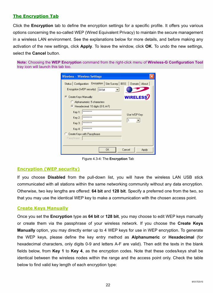
The Encryption Tab
Click the Encryption tab to define the encryption settings for a specific profile. It offers you various options concerning the so-called WEP (Wired Equivalent Privacy) to maintain the secure management in a wireless LAN environment. See the explanations below for more details, and before making any activation of the new settings, click Apply. To leave the window, click OK. To undo the new settings, select the Cancel button.
Note: Choosing the WEP Encryption command from the right-click menu of Wireless-G Configuration Tool tray icon will launch this tab too.
Figure 4.3-4: The Encryption Tab
Encryption (WEP security)
If you choose Disabled from the pull-down list, you will have the wireless LAN USB stick communicated with all stations within the same networking community without any data encryption. Otherwise, two key lengths are offered: 64 bit and 128 bit. Specify a preferred one from the two, so that you may use the identical WEP key to make a communication with the chosen access point.
Create Keys Manually
Once you set the Encryption type as 64 bit or 128 bit, you may choose to edit WEP keys manually or create them via the passphrase of your wireless network. If you choose the Create Keys Manually option, you may directly enter up to 4 WEP keys for use in WEP encryption. To generate the WEP keys, please define the key entry method as Alphanumeric or Hexadecimal (for hexadecimal characters, only digits 0-9 and letters A-F are valid). Then edit the texts in the blank fields below, from Key 1 to Key 4, as the encryption codes. Note that these codes/keys shall be identical between the wireless nodes within the range and the access point only. Check the table below to find valid key length of each encryption type:
M101703V10 23
64 bit 128 bit Alphanumeric 5 characters 13 characters Hexadecimal 10 digits 26 digits
Use WEP Key
Indicate which WEP key you intend to apply to activate the WEP encryption from the pull-down menu. Make sure that the intended access point on the wireless network shares the same keys. By default, Key 1 will be used.
Create Keys with Passphrase
Choose this command when the associated wireless network uses a passphrase to create WEP keys. Enter the passphrase string in the Passphrase filed to generate four encryption keys in the Key fields above. Note that only letters A-F are valid for the Passphrase feature.
Note: When entering the passphrase here, ensure that you have specified an accurate type of the Encryption (WEP security) above according to the associated agent’s configuration. Otherwise, the inaccuracy will cause any failure of performance.
After finish configuring the Encryption features, remember to click Apply to initiate the new settings.
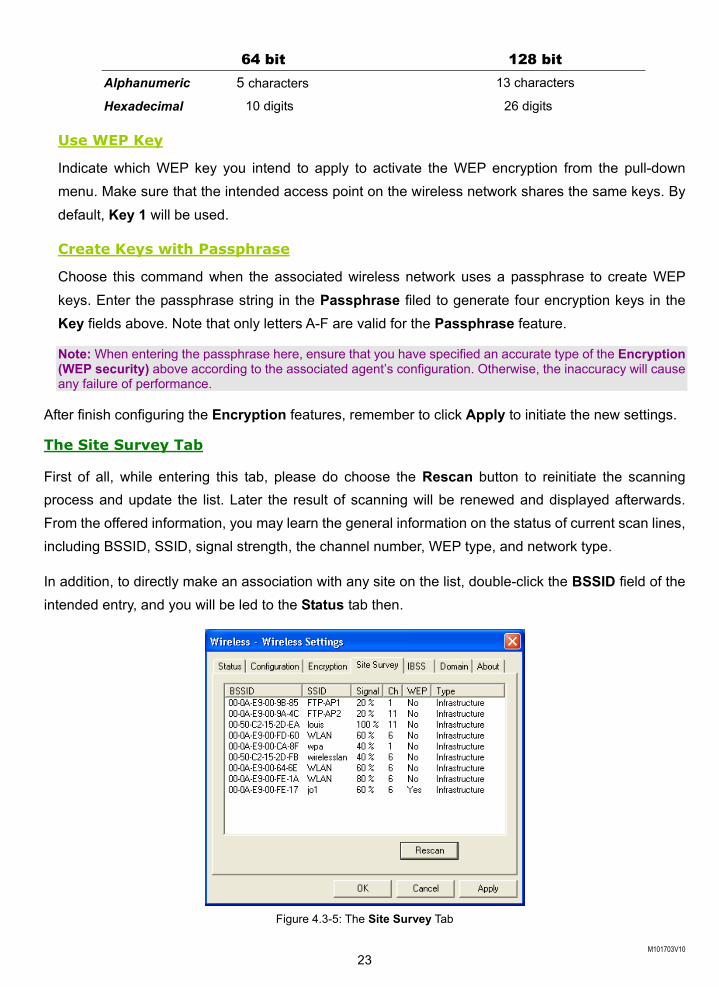
The Site Survey Tab
First of all, while entering this tab, please do choose the Rescan button to reinitiate the scanning process and update the list. Later the result of scanning will be renewed and displayed afterwards. From the offered information, you may learn the general information on the status of current scan lines, including BSSID, SSID, signal strength, the channel number, WEP type, and network type.
In addition, to directly make an association with any site on the list, double-click the BSSID field of the intended entry, and you will be led to the Status tab then.
Figure 4.3-5: The Site Survey Tab
M101703V10 24
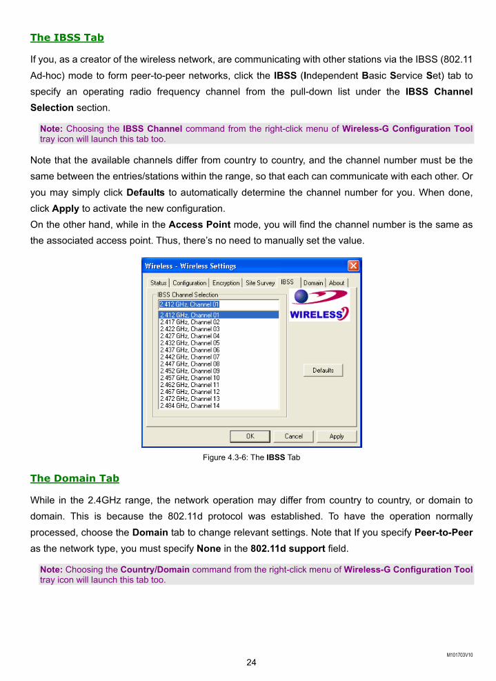
The IBSS Tab
If you, as a creator of the wireless network, are communicating with other stations via the IBSS (802.11 Ad-hoc) mode to form peer-to-peer networks, click the IBSS (Independent Basic Service Set) tab to specify an operating radio frequency channel from the pull-down list under the IBSS Channel Selection section.
Note: Choosing the IBSS Channel command from the right-click menu of Wireless-G Configuration Tool tray icon will launch this tab too.
Note that the available channels differ from country to country, and the channel number must be the same between the entries/stations within the range, so that each can communicate with each other. Or you may simply click Defaults to automatically determine the channel number for you. When done, click Apply to activate the new configuration. On the other hand, while in the Access Point mode, you will find the channel number is the same as the associated access point. Thus, there’s no need to manually set the value.
Figure 4.3-6: The IBSS Tab
The Domain Tab
While in the 2.4GHz range, the network operation may differ from country to country, or domain to domain. This is because the 802.11d protocol was established. To have the operation normally processed, choose the Domain tab to change relevant settings. Note that If you specify Peer-to-Peer as the network type, you must specify None in the 802.11d support field.
Note: Choosing the Country/Domain command from the right-click menu of Wireless-G Configuration Tool tray icon will launch this tab too.
M101703V10 25
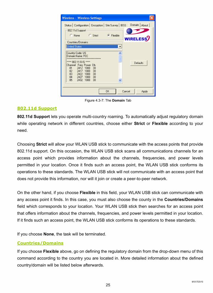
Figure 4.3-7: The Domain Tab
802.11d Support
802.11d Support lets you operate multi-country roaming. To automatically adjust regulatory domain while operating network in different countries, choose either Strict or Flexible according to your need. Choosing Strict will allow your WLAN USB stick to communicate with the access points that provide 802.11d support. On this occasion, the WLAN USB stick scans all communications channels for an access point which provides information about the channels, frequencies, and power levels permitted in your location. Once it finds such an access point, the WLAN USB stick conforms its operations to these standards. The WLAN USB stick will not communicate with an access point that does not provide this information, nor will it join or create a peer-to-peer network. On the other hand, if you choose Flexible in this field, your WLAN USB stick can communicate with any access point it finds. In this case, you must also choose the county in the Countries/Domains field which corresponds to your location. Your WLAN USB stick then searches for an access point that offers information about the channels, frequencies, and power levels permitted in your location. If it finds such an access point, the WLAN USB stick conforms its operations to these standards. If you choose None, the task will be terminated.
Countries/Domains
If you choose Flexible above, go on defining the regulatory domain from the drop-down menu of this command according to the country you are located in. More detailed information about the defined country/domain will be listed below afterwards.
M101703V10 26
When you are done, remember to click Apply to let the new settings take effect.
The About Tab
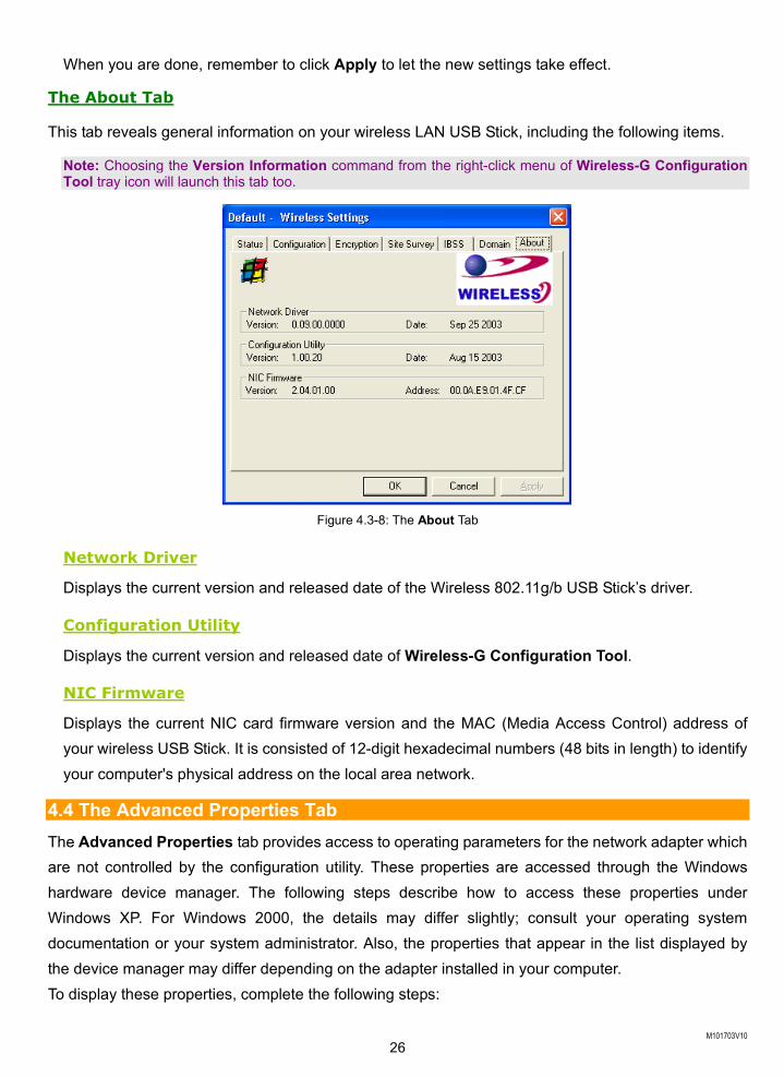
This tab reveals general information on your wireless LAN USB Stick, including the following items.
Note: Choosing the Version Information command from the right-click menu of Wireless-G Configuration Tool tray icon will launch this tab too.
Figure 4.3-8: The About Tab
Network Driver
Displays the current version and released date of the Wireless 802.11g/b USB Stick’s driver.
Configuration Utility
Displays the current version and released date of Wireless-G Configuration Tool.
NIC Firmware
Displays the current NIC card firmware version and the MAC (Media Access Control) address of your wireless USB Stick. It is consisted of 12-digit hexadecimal numbers (48 bits in length) to identify your computer's physical address on the local area network.
4.4 The Advanced Properties Tab The Advanced Properties tab provides access to operating parameters for the network adapter which are not controlled by the configuration utility. These properties are accessed through the Windows hardware device manager. The following steps describe how to access these properties under Windows XP. For Windows 2000, the details may differ slightly; consult your operating system documentation or your system administrator. Also, the properties that appear in the list displayed by the device manager may differ depending on the adapter installed in your computer. To display these properties, complete the following steps:
M101703V10 27
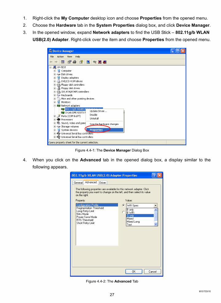
1. Right-click the My Computer desktop icon and choose Properties from the opened menu. 2. Choose the Hardware tab in the System Properties dialog box, and click Device Manager. 3. In the opened window, expand Network adapters to find the USB Stick – 802.11g/b WLAN
USB(2.0) Adapter. Right-click over the item and choose Properties from the opened menu.
Figure 4.4-1: The Device Manager Dialog Box
4. When you click on the Advanced tab in the opened dialog box, a display similar to the following appears.
Figure 4.4-2: The Advanced Tab
M101703V10 28
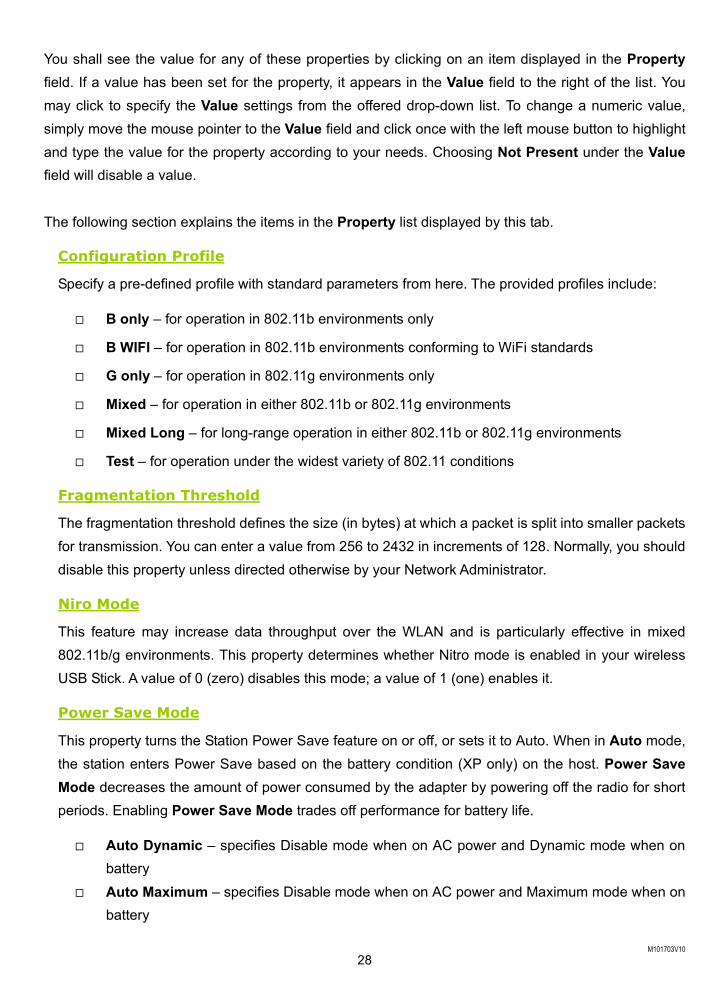
You shall see the value for any of these properties by clicking on an item displayed in the Property field. If a value has been set for the property, it appears in the Value field to the right of the list. You may click to specify the Value settings from the offered drop-down list. To change a numeric value, simply move the mouse pointer to the Value field and click once with the left mouse button to highlight and type the value for the property according to your needs. Choosing Not Present under the Value field will disable a value. The following section explains the items in the Property list displayed by this tab.
Configuration Profile
Specify a pre-defined profile with standard parameters from here. The provided profiles include:
B only – for operation in 802.11b environments only
B WIFI – for operation in 802.11b environments conforming to WiFi standards
G only – for operation in 802.11g environments only
Mixed – for operation in either 802.11b or 802.11g environments
Mixed Long – for long-range operation in either 802.11b or 802.11g environments
Test – for operation under the widest variety of 802.11 conditions
Fragmentation Threshold
The fragmentation threshold defines the size (in bytes) at which a packet is split into smaller packets for transmission. You can enter a value from 256 to 2432 in increments of 128. Normally, you should disable this property unless directed otherwise by your Network Administrator.
Niro Mode
This feature may increase data throughput over the WLAN and is particularly effective in mixed 802.11b/g environments. This property determines whether Nitro mode is enabled in your wireless USB Stick. A value of 0 (zero) disables this mode; a value of 1 (one) enables it.
Power Save Mode
This property turns the Station Power Save feature on or off, or sets it to Auto. When in Auto mode, the station enters Power Save based on the battery condition (XP only) on the host. Power Save Mode decreases the amount of power consumed by the adapter by powering off the radio for short periods. Enabling Power Save Mode trades off performance for battery life.
Auto Dynamic – specifies Disable mode when on AC power and Dynamic mode when on battery
Auto Maximum – specifies Disable mode when on AC power and Maximum mode when on battery
M101703V10 29
Note: Auto Dynamic and Auto Maximum require NDIS 5.1 or later, typically available only on Windows XP.
Disabled – specifies continuous access mode and is the default Dynamic – specifies a fast power saving mode that provides the best combination of
performance and power usage Maximum – specifies the greatest power saving mode
RTS Threshold
The RTS threshold is the packet size (in bytes) at which packet transmission is governed by the RTS/CTS transaction. You can enter a value from 0 to 2432 in increments of 64 for this property. Normally you should leave this property disabled unless directed otherwise by your Network Administrator.
The Long/Short Retry Limit
The Long Retry Limit or Short Retry Limit is the maximum number of retransmission of a data packet because of the failure of receiving CTS or ACK.
M101703V10 30
APPENDIX A: TROUBLESHOOTING
This section provides solutions to problems that you might encounter during the installation and operation of your Wireless 802.11g/b USB Stick. Please refer to the desired topics below and read the description to solve your problems.
Uninstall Wireless-G Configuration Tool and the Stick’s Driver Prior to starting the uninstalling, please make sure that Wireless-G Configuration Tool is closed, and then go along with the procedures below to entirely uninstall Wireless-G Configuration Tool and the Stick driver.
1. Right-click the My Computer desktop icon and choose Properties from the opened menu. 2. In the System Properties dialog box, click the Hardware tab, and then choose the Device
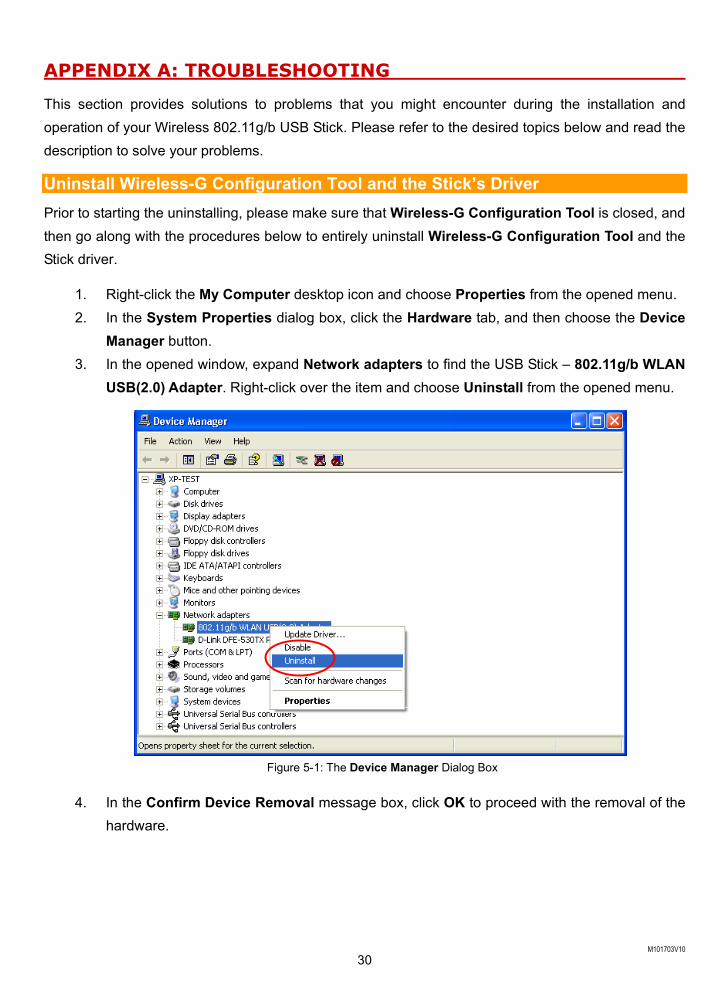
Manager button. 3. In the opened window, expand Network adapters to find the USB Stick – 802.11g/b WLAN
USB(2.0) Adapter. Right-click over the item and choose Uninstall from the opened menu.
Figure 5-1: The Device Manager Dialog Box
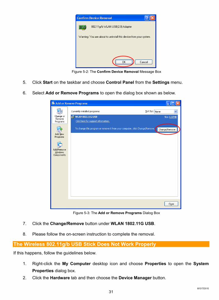
4. In the Confirm Device Removal message box, click OK to proceed with the removal of the hardware.
M101703V10 31
Figure 5-2: The Confirm Device Removal Message Box
5. Click Start on the taskbar and choose Control Panel from the Settings menu.
6. Select Add or Remove Programs to open the dialog box shown as below.
Figure 5-3: The Add or Remove Programs Dialog Box
7. Click the Change/Remove button under WLAN 1802.11G USB.
8. Please follow the on-screen instruction to complete the removal.
The Wireless 802.11g/b USB Stick Does Not Work Properly If this happens, follow the guidelines below.
1. Right-click the My Computer desktop icon and choose Properties to open the System Properties dialog box.
2. Click the Hardware tab and then choose the Device Manager button.
M101703V10 32
3. In the opened window, find your USB Stick to see if the installation is successful. If you see a yellow exclamation mark beside the item, please go along with the steps below to reinstall the drivers.
4. Uninstall the software and hardware drivers from your PC. (Please refer to the previous topic for details)
5. Restart your computer and repeat the installation procedures as indicated in this chapter in this manual: Installation of the Wireless 802.11g/b USB Stick.
6. When finished, open the Device Manager window again to verify if the installation is approved. The yellow exclamation mark shall be removed for this time.
Upgrade WLAN-G Configuration Tool and the Stick’s Driver
To upgrade the drivers for WLAN-G Configuration Tool and the Wireless 802.11g/b USB Stick, follow the procedures below. Please note that the details might be slightly different according to the Windows system you are using. Here we are taking the example of Windows XP.
1. Click Start on the taskbar and choose Control Panel from the Settings menu. 2. Select System to open the System Properties dialog box, and then under the Hardware
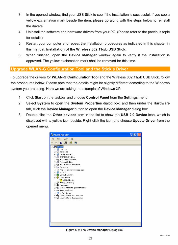
tab, click the Device Manager button to open the Device Manager dialog box. 3. Double-click the Other devices item in the list to show the USB 2.0 Device icon, which is
displayed with a yellow icon beside. Right-click the icon and choose Update Driver from the opened menu.
Figure 5-4: The Device Manager Dialog Box
M101703V10 33
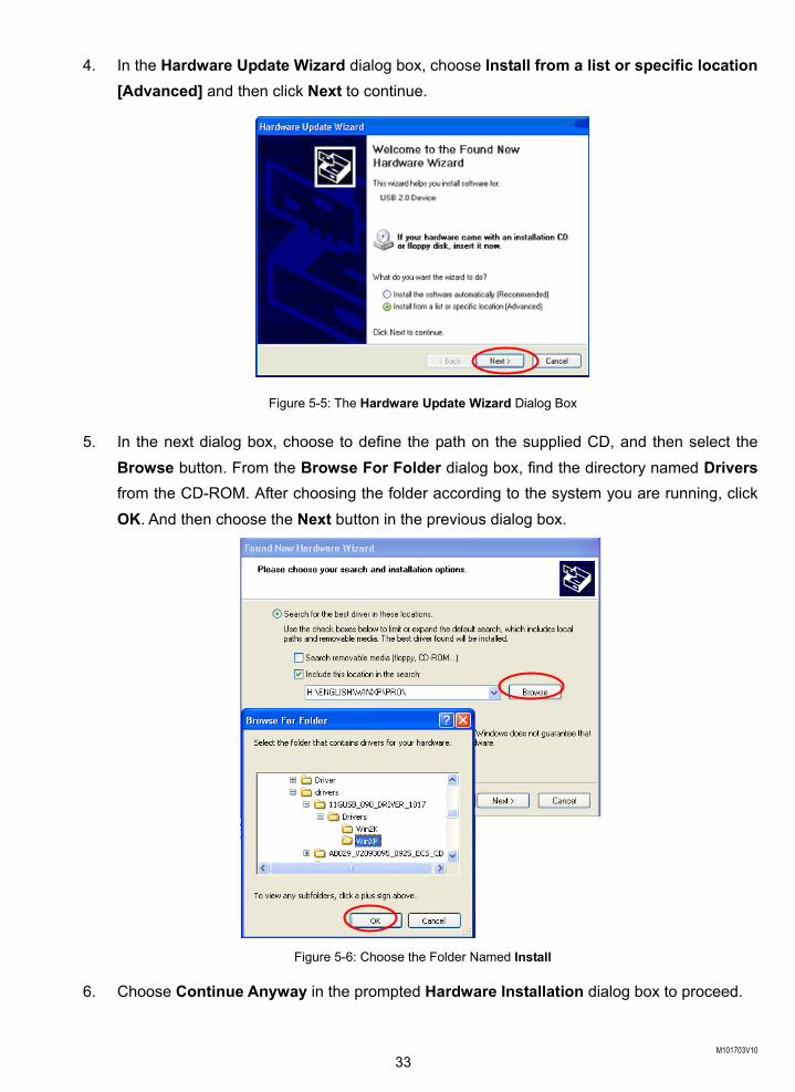
4. In the Hardware Update Wizard dialog box, choose Install from a list or specific location [Advanced] and then click Next to continue.
Figure 5-5: The Hardware Update Wizard Dialog Box
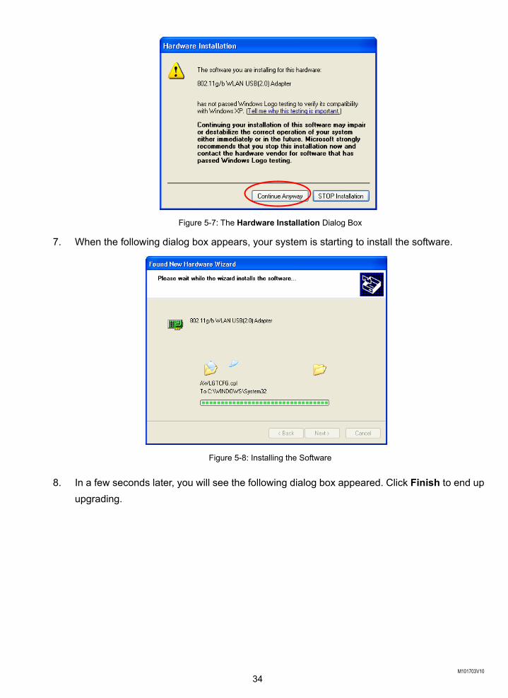
5. In the next dialog box, choose to define the path on the supplied CD, and then select the Browse button. From the Browse For Folder dialog box, find the directory named Drivers from the CD-ROM. After choosing the folder according to the system you are running, click OK. And then choose the Next button in the previous dialog box.
Figure 5-6: Choose the Folder Named Install
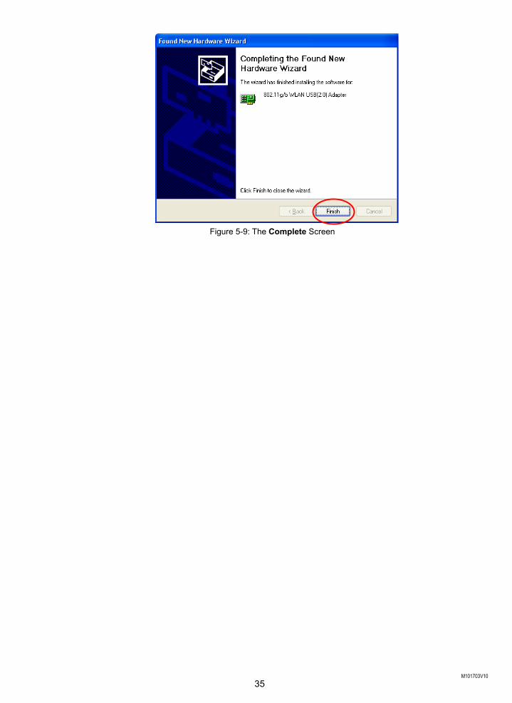
6. Choose Continue Anyway in the prompted Hardware Installation dialog box to proceed.
M101703V10 34
Figure 5-7: The Hardware Installation Dialog Box
7. When the following dialog box appears, your system is starting to install the software.
Figure 5-8: Installing the Software
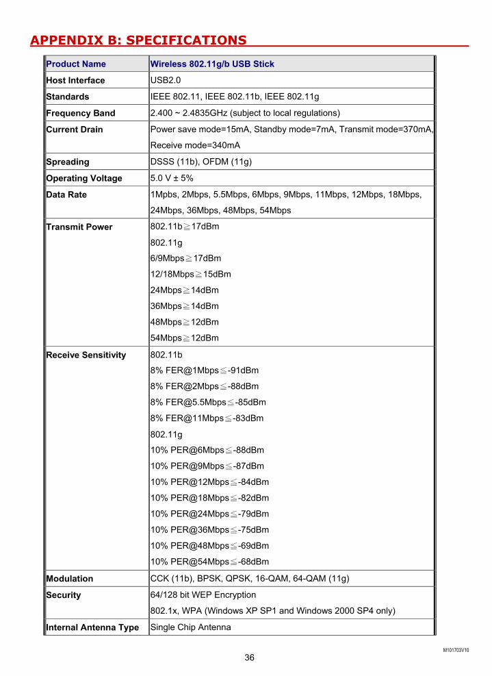
8. In a few seconds later, you will see the following dialog box appeared. Click Finish to end up upgrading.
M101703V10 35
Figure 5-9: The Complete Screen
M101703V10 36
APPENDIX B: SPECIFICATIONS
Product Name Wireless 802.11g/b USB Stick
Host Interface USB2.0
Standards IEEE 802.11, IEEE 802.11b, IEEE 802.11g
Frequency Band 2.400 ~ 2.4835GHz (subject to local regulations)
Current Drain Power save mode=15mA, Standby mode=7mA, Transmit mode=370mA,
Receive mode=340mA
Spreading DSSS (11b), OFDM (11g)
Operating Voltage 5.0 V ± 5%
Data Rate 1Mpbs, 2Mbps, 5.5Mbps, 6Mbps, 9Mbps, 11Mbps, 12Mbps, 18Mbps,
24Mbps, 36Mbps, 48Mbps, 54Mbps
Transmit Power 802.11b≧17dBm
802.11g
6/9Mbps≧17dBm
12/18Mbps≧15dBm
24Mbps≧14dBm
36Mbps≧14dBm
48Mbps≧12dBm
54Mbps≧12dBm
Receive Sensitivity 802.11b
8% FER@1Mbps≦-91dBm
8% FER@2Mbps≦-88dBm
8% [email protected]≦-85dBm
8% FER@11Mbps≦-83dBm
802.11g
10% PER@6Mbps≦-88dBm
10% PER@9Mbps≦-87dBm
10% PER@12Mbps≦-84dBm
10% PER@18Mbps≦-82dBm
10% PER@24Mbps≦-79dBm
10% PER@36Mbps≦-75dBm
10% PER@48Mbps≦-69dBm
10% PER@54Mbps≦-68dBm
Modulation CCK (11b), BPSK, QPSK, 16-QAM, 64-QAM (11g)
Security 64/128 bit WEP Encryption
802.1x, WPA (Windows XP SP1 and Windows 2000 SP4 only)
Internal Antenna Type Single Chip Antenna

M101703V10 37
Media Access Control RF activity
Supplied Driver CSMA/CA with ACK
Warranty 1 year
Temperature Range 0~65°C (Operating)
Humidity Max. 95% Non-condensing
Operating Range Open Space: up to 400meters; Indoor: up to 100meters The transmission speed varies in the surrounding environment.
M101703V10 38
APPENDIX C: GLOSSARY
802.11b – 802.11b is one of the IEEE standards for wireless LANs and specifies a data transfer rate of 5.5 and up to 11 megabit per second in the 2.4 gigahertz radio band. 802.11b is recently given other widespread names as Wi-Fi or Wireless Fidelity. 802.11g – Ad-hoc Network – Ad-hoc network, also known as peer-to-peer network, means a wireless network which is composed only of stations. This type of network is created with a group of wireless-equipped computers. With the wireless devices, each computer, functioning as a server and a client at the same time, can establish a LAN to directly communicate with other computers without any access points involved. It is easy to set up a peer-to-peer network; however, because all stations must be within a specific distance in order to be capable of communicating with each other, it is also limited. Thus, such a type of network is widely used at small networking requirements, like between a few computers or devices at departmental scales. IEEE – IEEE, the Institute of Electrical and Electronics Engineers, is the world’s largest technical professional society and is consisted of more than 366,000 members in approximately 150 countries. As a leading authority on areas ranging from for computer engineering, biomedical technology and telecommunications, IEEE endeavours to set more than 800 active consensus standards till now and publish 30 percent of the world's literature in electrical engineering, computers and control technology. Infrastructure Network – Infrastructure network allows you to communicate with wired LAN via an access point. Unlike Ad-hoc network that all wireless-equipped stations within the range may directly communicate with each other, clients of Infrastructure network can only transmit and receive data through the use of a central access point. The associated access point also provides communication with the wired network. MAC Address – The MAC (Media Access Control) address is the serial number of your Network Interface card. It has been burnt into the chip and could not be changed. MAC address is thus unique. While a computer on the network is transferring data, its MAC address is also conveyed and attached to be part of the header of the data packets. Roaming – Roaming is an ability to allow users from one cell (or BSS) to another without losing connection via a wireless device.
M101703V10 39
SSID – SSID, Service Set Identifier, is a 32-character unique identifier for a workgroup of the wireless network. An SSID of one WLAN should be different from that of others, so all access points and other devices intending to communicate with a specific WLAN cannot achieve successful network connectivity unless presenting the identical SSID. From some perspective, an SSID performs as a kind of password to supply a measure of security on the WLAN. However, if an access point is configured to “broadcast” its SSID, this essential security is no longer remained. An SSID is also known as a Network Name. USB – USB, standing for Universal Serial Bus, was designed to make a connection between the computer and its peripherals, such as keyboards, scanners, webcams, printers, etc., via an easy operation of plug-and-play. USB has proved to be a good solution that allows users to quickly and easily connect and add peripherals to computers. Through the USB interface, there’s even no need to turn the computer off while adding new peripherals mentioned above to a computer. Due to its convenience and simplicity, USB has won worldwide popularity, and most peripherals for computers these days are designed for the USB standard. WEP – Wired Equivalent Privacy (WEP) is a security mechanism for wireless local area networks. It is designed for 802.11 standard to offer an equal level of security as that of a wired LAN. Through the configurations of encryption, WEP aims to provide security while the nodes with wireless devices are transferring or receiving data packets over radio waves. WLAN – Wireless local area network (WLAN) receive and transmit data over the air by using radio frequency (RF) technology. The vital significance of WLAN is it minimizes the requirements for wired connections and provides not only data connectivity but also user mobility. Without the constraint of physical location, wireless LAN allows clients to transmit and receive data via high-frequency radio waves rather than wires.