Embed Size (px)
Citation preview

Wire Rope SlingCatalog

Three Locations To Serve You
Corpus Christi
San Antonio
Houston
302 Flato RoadCorpus Christi, TX 78405361-289-1444 • 800-289-1445Fax: 361-289-7555
4202 Dividend DrSan Antonio, TX 78219210-527-0555 • 877-527-0555Fax: 210-527-9701
5600 Surrey SquareHouston, TX 77017713-673-7881 • 800-392-5510Fax: 713-673-2901
Locations

WIRE ROPE SLINGSIntroduction
Wire rope slings are the most common type of sling that Kennedy Wire Rope & Sling fabricates. These slings consist ���������������������������multi-part braided constructions. ����������������������������������������������������
Kennedy Wire Rope & Sling fabricates wire rope slings and assemblies with diameters from 1/32” to 4-1/2”. We use various types and constructions of wire rope when fabricating slings, bright with an exterior lubrication, galvanized wire, and stainless steel. �������������������������depending on applications.
WarrantyAny warranty expressed or implied as to quality performance, or ������������������������������������rated capacities apply only to new, unused slings and assemblies, that the mechanical equipment on which such products are properly stored, handled, and used and maintained, and properly inspected on a regular basis during the period of use.
Seller shall not be liable under any circumstance for consequential or incidental damages or secondary charges including (but not limited to) personal injury�������������������������������products or from said products being incorporated in or becoming a component of any other product
For more information, visit us at www.kwrs.com
Page
4
Table of Contents
Wire Rope Sling Capacities & Hitches 5-7D/d Ratios 8Care and Maintenance 9Inspection Criteria 10Type 110 Hand Spliced Slings 11Type 115 Mechanically Spliced Slings 12Type 125 Two Leg Spreaders 13Type 135 Three Leg Spreaders 14Type 145 Four Leg Spreaders 15Type 315 Three Part Braid Slings 16Type 615 Six Part Braid Slings 17Type 815 Eight Part Braid Slings 18Type 915 Nine Part Braid Slings 19Type 8P1 8 Part Braid Slings (7X19 Galv. Cable) 20Type 8P2 8 Part Braid Two Leg Spreaders (7X19 Galv. Cable) 21
Type 8P3 8 Part Braid Three Leg Spreaders (7X19 Galv. Cable) 22
Type 8P4 8 Part Braid Four Leg Spreaders (7X19 Galv. Cable) 23Type 110 Wire Rope Assemblies (Spelter Sockets) 24Type 115 Wire Rope Assemblies (Swage Sockets) 25Type 210 Strand Laid Grommets 26Type 215 Mechanical Splice Grommets 27Type 270 Cable Laid Hand Splice Grommets 28Type CL15 Galvanized Cable Laid Slings 29Type CL25 Galvanized Cable Laid Two Leg Spreaders 30Type CL35 Galvanized Cable Laid Three Leg Spreaders 31Type CL45 Galvanized Cable Laid Four Leg Spreaders 32Type SS15 T-304 Stainless Steel Slings 33Type SS25 T-304 Stainless Steel Two Leg Spreaders 34
Type SS35 T-304 Stainless Steel Three Leg Spreaders 35
Type SS45 T-304 Stainless Steel Four Leg Spreaders 36Model S-320 Crosby Eye Hooks 37-38
5
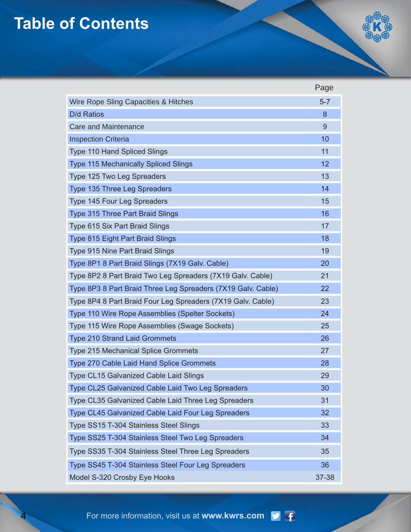
The listed capacities of wire rope slings/assemblies in this catalog are based on the industrial standard of a 5 to 1 design factor. This is the method used to determine the working load limit (WLL) of a sling: minimum breaking strength of the wire rope (MBL) ���������������������������������������������
���������������������������������
��������������������������� • Type of hitch being used when lifting the load • Diameter of the item being lifted where the sling is attached • Diameter of the hook or shackle where the sling attaches to the lifting device
Efficiency of the end termination or eye spliceHand spliced eyes:
Rope Diameter Efficiency1/4" 90%5/16" 89%3/8" 88%7/16" 87%1/2" 86%9/16" 85%5/8" 84%3/4" 82%7/8" to 2-1/2" 80%
Mechanical spliced eyes:
Rope Diameter Efficiency1/4" to 1" 95%1-1/8" to 2" 92.5%2-1/4" to 4-1/2" 90%
Swage and spelter sockets:
Rope Diameter Efficiency1/4" to 4-1/2" 100%
WIRE ROPE SLINGSCapacities & Hitches
For more information, visit us at www.kwrs.com

WIRE ROPE SLINGS
For more information, visit us at www.kwrs.com
Capacities & Hitches
Type of hitch being used when lifting the load:
Vertical Pull:A vertical pull is where a sling is hitched between the lifting device and load in a straight line.
Choker Hitch:A choker hitch is where the eye on one end of the sling is passed through the eye on the other end of the sling and the sling is choked around the load being picked up. The chart below shows the capacity reduction of a sling used in a choker hitch.
Angle of Choke Degree Rated Capacity %Over 120 10090-120 8760-89 7430-59 620-29 49
Vertical Basket Hitch:A vertical basket hitch is where the body of the sling supports the load being lifted and the two ends of the sling are attached to the lifting device.
6

WIRE ROPE SLINGS
For more information, visit us at www.kwrs.com
Capacities & Hitches
7
Sling Capacities When Rigged at Various Angles
Leg Angle Load Factor90° 1.00085° 1.00380° 1.01575° 1.03570° 1.06465° 1.10360° 1.15455° 1.22050° 1.30545° 1.41440° 1.55535° 1.74330° 2.000
LoadFactorGuidelinesA. Vertical lift: Total load is 1,000 lbs. divided by two legs = 500 lbs. load per leg if vertical lift
B. Horizontal sling angle is 60 degrees: Multiply 500 lbs. by 1.154 load factor (from table) = 577 lbs. Actual load per leg.
A. Vertical lift: Total load is 1,000 lbs. divided by two legs = 500 lbs. load per leg if vertical lift
B. Horizontal sling angle is 45 degrees: Multiply 500 lbs. by 1.414 load factor (from table) = 707 lbs. Actual load per leg.
A. Vertical lift: Total load is 1,000 lbs. divided by two legs = 500 lbs. load per leg if vertical lift
B. Horizontal sling angle is 30 degrees: Multiply 500 lbs. by 2.000 load factor (from table) = 1000 lbs. Actual load per leg.
WARNING: Slings shall not be used with horizontal angles less than 30°.
EXAMPLES:

When a sling is rigged as a basket, the diameter of the bend where the sling contacts the load can ���������s lifting capacity�������������������������������������the diameter of the bend where the rope contacts the load (represented by “D”) by the diameter of the rope or the component rope diameter in a multi-part sling (represented by “d”).
For example, if the diameter of the bend (“D”) is 10 and the component rope diameter (“d”) is 1/2, the D/d ratio is 10÷1/2 or 20.
When using D/d ratios that are smaller than those shown in the table below, the rated capacity of the sling must be decreased.
Mechanically spliced, single-part slings 25 times rope diameter
Hand-spliced, single-part slings 15 times rope diameter
Braided multi-part slings of 3 parts 10 times component rope diameter
Braided multi-part slings of 6 parts 25 times component rope diameter
Braided multi-part slings of 8 parts 25 times component rope diameter
Braided multi-part slings of 9 parts 20 times component rope diameter
Hand-tucked grommets andmechanically joined grommets 5 times sling body diameter
StandardD/dratiosareappliedtodetermineefficiencyofvariousslingconstructions
WIRE ROPE SLINGSD/d Ratios
8 For more information, visit us at www.kwrs.com

9
Care and Maintenance WIRE ROPE SLINGS
Wire Rope is lubricated during manufacturing so that the strands - as well as the individual wires in the strands - may move and adjust as the rope moves and bends. No wire rope can be lubricated sufficiently during manufacturing to last its entire life. That’s why it’s important to lubricate periodically through the life of the rope.
The surface of some ropes may be covered with dirt, rock dust or other material during their operation. This can prevent field-applied lubricants from properly penetrating into the rope, so it’s a good practice to clean these ropes before you lubricate them.
The lubricant you apply should be light-bodied enough to penetrate to the rope’s core. You can normally apply lubricant by using one of three methods: - Drip it on the rope - Spray it on the rope - Brush it onto the rope
Your rope’s service life will be directly proportional to the effectiveness of the method you use and the amount of lubricant that reaches the ropes working parts.
A proper lubricant must reduce friction, protect against corrosion and adhere to every wire. It should also be pliable and not crack or separate when cold - yet not drip when warm. Never apply heavy grease to the rope because it can trap excessive grit which can damage the rope. Nor should you apply used “engine oil” because it contains materials that can damage the wire rope.
Wire Rope Sling Storage and Handling
Wire Rope slings should be kept in an area where exposure to water, extreme heat or corrosive fumes, liquids and sprays are non-existent.
Slings should also be kept out of the way where they may get ran over by vehicles or kinked.
Slings should never be left beneath loads or laying where they could be possibly damaged.
Wire Rope Sling Temperature
Wire rope should be protected from extreme temperatures. Steel core (IWRC) slings should never be used at 400° F or more and never below -40°F.
It is not always easy to spot when wire rope has been damaged by heat. The most visible signs are loss of lubrication, discoloration and fusing of the wires.
If there is even the slightest suspicion that a sling was exposed to heat then it should be removed from service immediately.
WIRE ROPE SLINGS
For more information, visit us at www.kwrs.com
Inspection Criteria
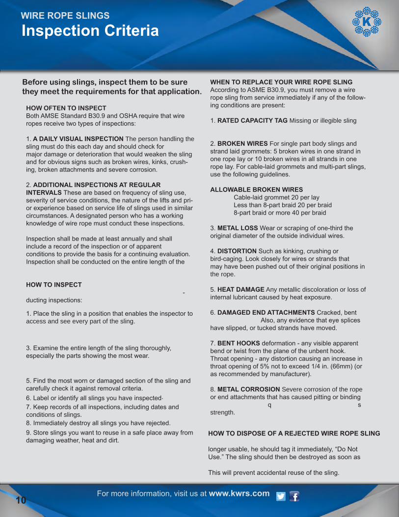
Before using slings, inspect them to be sure they meet the requirements for that application.
HOW OFTEN TO INSPECTBoth AMSE Standard B30.9 and OSHA require that wire ropes receive two types of inspections:
1. A DAILY VISUAL INSPECTION The person handling the sling must do this each day and should check for major damage or deterioration that would weaken the sling and for obvious signs such as broken wires, kinks, crush-ing, broken attachments and severe corrosion.
2. ADDITIONAL INSPECTIONS AT REGULAR INTERVALS These are based on frequency of sling use, severity of service conditions, the nature of the lifts and pri-or experience based on service life of slings used in similar circumstances. A designated person who has a working knowledge of wire rope must conduct these inspections.
Inspection shall be made at least annually and shall include a record of the inspection or of apparent conditions to provide the basis for a continuing evaluation. Inspection shall be conducted on the entire length of the ����������������������������
HOW TO INSPECT����������������������������-ducting inspections:
1. Place the sling in a position that enables the inspector to access and see every part of the sling. ��������������������������������������������3. Examine the entire length of the sling thoroughly, especially the parts showing the most wear.����������������������������������������������������5. Find the most worn or damaged section of the sling and carefully check it against removal criteria.6. Label or identify all slings you have inspected.7. Keep records of all inspections, including dates and conditions of slings.8. Immediately destroy all slings you have rejected. 9. Store slings you want to reuse in a safe place away from damaging weather, heat and dirt.
WHEN TO REPLACE YOUR WIRE ROPE SLINGAccording to ASME B30.9, you must remove a wire rope sling from service immediately if any of the follow-ing conditions are present:
1. RATED CAPACITY TAG Missing or illegible sling����������
2. BROKEN WIRES For single part body slings and strand laid grommets: 5 broken wires in one strand in one rope lay or 10 broken wires in all strands in one rope lay. For cable-laid grommets and multi-part slings, use the following guidelines.
ALLOWABLE BROKEN WIRES Cable-laid grommet 20 per lay Less than 8-part braid 20 per braid 8-part braid or more 40 per braid
3. METAL LOSS Wear or scraping of one-third theoriginal diameter of the outside individual wires.
4. DISTORTION Such as kinking, crushing or bird-caging. Look closely for wires or strands that may have been pushed out of their original positions in the rope.
5. HEAT DAMAGE Any metallic discoloration or loss of internal lubricant caused by heat exposure.
6. DAMAGED END ATTACHMENTS Cracked, bent����������Also, any evidence that eye splices have slipped, or tucked strands have moved.
7. BENT HOOKS deformation - any visible apparent bend or twist from the plane of the unbent hook. Throat opening - any distortion causing an increase in throat opening of 5% not to exceed 1/4 in. (66mm) (or as recommended by manufacturer).
8. METAL CORROSION Severe corrosion of the rope or end attachments that has caused pitting or binding ����������������������������s strength.
HOW TO DISPOSE OF A REJECTED WIRE ROPE SLING���������������������������longer usable, he should tag it immediately, “Do NotUse.” The sling should then be destroyed as soon as����������������������������This will prevent accidental reuse of the sling.
10
WIRE ROPE SLINGS
For more information, visit us at www.kwrs.com11
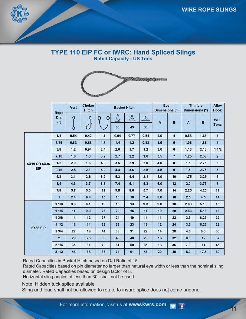
Note: Hidden tuck splice availableSling and load shall not be allowed to rotate to insure splice does not come undone.
TYPE 110 EIP FC or IWRC: Hand Spliced Slings Rated Capacity - US Tons
Rated Capacities in Basket Hitch based on D/d Ratio of 15.Rated Capacities based on pin diameter no larger than natural eye width or less than the nominal sling diameter. Rated Capacities based on design factor of 5.Horizontal sling angles of less than 30° shall not be used.

For more information, visit us at www.kwrs.com
Rated Capacities in Basket Hitch based on D/d Ratio of 25.Rated Capacities based on pin diameter no larger than natural eye width or less than the nominal sling diameter. Rated Capacities based on design factor of 5.Horizontal sling angles of less than 30° shall not be used.
WIRE ROPE SLINGS
TYPE 115 EIP IWRC: Mechanical Spliced SlingsRated Capacity - US Tons
12

WIRE ROPE SLINGS
For more information, visit us at www.kwrs.com 13
Rated Capacities based on design factor of 5.Horizontal sling angles of less than 30° shall not be used.
TYPE 125 EIP IWRC: Mechanical Spliced Two Leg SpreadersRated Capacity - US Tons
2.0 2240 28 2.25 30
11 7.6 1.25 1111
17 12 1.50 15
4.5 3.2 0.875 5
1.9 0.75
57.9 5.6 1.0 7
1.4 0.50 1 1/2
0.91 0.65 0.50
23.6 2.5 0.63 34.4
9/16 5.53.9 1.05/8 6.8 5.5
Alloy Hook
Alloy Oblong
RATED CAPACITY(Tons)
1/4 1.15/16 1.73/8 2.5
WLLTons
11.4 1.0 0.50 12.0
372 63 521 3/4 49
37 2.5
1 1/8 211 1/4 26
18 1.751 3/8 31 2521 15 1.75 15
2230 21
6x19 OR 6x36EIP
6x36 EIP
60 45 30
RopeDia.(”) Dia.
(")
1 1/2 37
3/4 9.77/8 13
9.8 1.501 17 14
7/16 3.4 2.71/2
For more information, visit us at www.kwrs.com
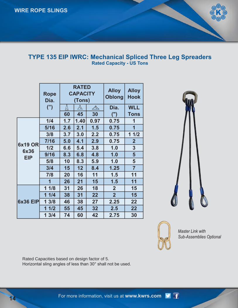
Rated Capacities based on design factor of 5.Horizontal sling angles of less than 30° shall not be used.
Master Link withSub-Assemblies Optional
WIRE ROPE SLINGS
TYPE 135 EIP IWRC: Mechanical Spliced Three Leg SpreadersRated Capacity - US Tons
14
1 1/2 551 3/4 74
WLLTons
6x19 OR 6x36EIP
6x36 EIP
60 45 30
RopeDia.(”) Dia.
(")
7/8 201 26
1 1/8 311 1/4 381 3/8 46
7/16 5.01/2 6.6
9/16 8.35/8 103/4 15
Alloy Hook
Alloy Oblong
RATED CAPACITY
(Tons)
1/4 1.75/16 2.63/8 3.7
12.1 1.5 0.75 13.0 2.2 0.75 1 1/2
1.40 0.97 0.75
25.4 3.8 1.0 36.8 4.8 1.0 5
4.1 2.9 0.75
512 8.4 1.25 716 11 1.5 11
8.3 5.9 1.0
1126 18 2 1531 22 2 15
21 15 1.5
2245 32 2.5 2260 42 2.75 30
38 27 2.25
WIRE ROPE SLINGS
For more information, visit us at www.kwrs.com 15
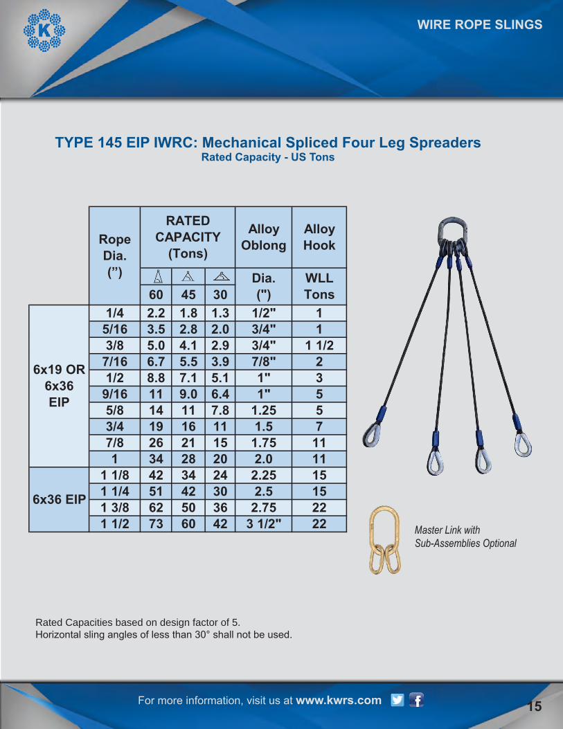
Rated Capacities based on design factor of 5.Horizontal sling angles of less than 30° shall not be used.
Master Link withSub-Assemblies Optional
TYPE 145 EIP IWRC: Mechanical Spliced Four Leg SpreadersRated Capacity - US Tons
2260 42 3 1/2" 22
36 2.7550
34 24 2.25 1542 30 2.5 15
21 15 1.75 11112.0
516 11 1.5 7
7.8 1.25
4.1 2.9 3/4" 1 1/2
6.4 1" 5
3.9 7/8" 25.1 1" 3
3/4" 1
Alloy Hook
Alloy Oblong
RATED CAPACITY
(Tons)
1/4 2.2
WLLTons
11.8 1.3 1/2"
Dia.(")
1 34 28
7/16 6.7 5.51/2 8.8
9/16 115/8 14 113/4 19
7.1
1 1/2 73
1 1/8 421 1/4 511 3/8 62
6x19 OR 6x36EIP
6x36 EIP
60 45 30
RopeDia.(”)
7/8 2620
5/16 3.53/8 5.0
2.8 2.0
9.0

Rated Capacities in Basket Hitch based on D/d ratio of 5 times the sling diameter. Rated capacities based on D/d ratio of 1.5 times the sling diameter inside the eye.
Note: Locked eyes available
WIRE ROPE SLINGS
TYPE 315 EIP: Three-Part Braided SlingRated Capacity - US Tons
Vertical HitchChoker Basket
Eye Width
Eye Length
1/4 1/2 1.7 1.3 3.4 2 45/16 5/8 2.6 1.9 5.2 3 63/8 3/4 3.6 2.7 7.2 4 8
7/16 7/8 4.9 3.7 9.8 5 101/2 1 6.4 4.8 12 6 12
9/16 1 1/8 8 6 16 7 145/8 1 1/4 9.9 7.4 19 8 163/4 1 1/2 14 10 28 10 207/8 1 3/4 19 14 38 12 241 2 24 18 49 14 28
1 1/8 2 1/4 31 23 62 16 321 1/4 2 1/2 38 28 76 18 361 3/8 2 3/4 46 34 92 20 401 1/2 3 55 41 110 22 441 3/4 3 1/2 73 54 146 26 52
2 4 95 71 190 28 562 1/4 4 1/2 118 88 236 32 642 1/2 5 145 109 290 36 722 3/4 5 1/2 173 130 346 40 80
3 6 204 153 408 44 883 1/2 7 270 202 540 48 96
4 8 343 257 686 56 1124 1/2 9 384 288 768 63 126
RATED CAPACITY (Tons) Eye
Dimensions (")
6X19 OR
6x36EIP
6X36 EIP
Rope Dia. (")
Sling Dia. (")
16 For more information, visit us at www.kwrs.com

WIRE ROPE SLINGS
Rated Capacities Basket Hitch based on D/d ratio of 25 times the component rope diameter.Rated Capacities based on pin diameter no larger than natural eye width or less than the nominal sling diameter.Rated Capacities based on design factor of 5.Horizontal sling angles less than 30° shall not be used.
TYPE 615 EIP IWRC: Six-Part Braided SlingRated Capacity - US Tons
Vertical HitchChoker
HitchBasket
A B ST HT
1/4 1 1/8 11/16 2.9 2.5 5.7 5 10 ST 20 5/85/16 1 3/8 7/8 4.4 3.9 8.9 6 12 ST 20 3/43/8 1 1 6.3 5.5 13 7 14 ST 24 7/87/16 2 1 3/16 8.6 7.5 17 8 16 ST 24 11/2 2 1/4 1 5/16 11 9.8 22 9 18 ST 36 1 1/89/16 2 1/2 1 1/2 14 12 28 10 20 ST 36 1 3/85/8 2 13/16 1 11/16 17 15 35 11 22 ST 44 1 1/23/4 3 3/8 2 26 22 49 12 24 ST 52 1 5/87/8 4 2 5/16 33 29 67 14 28 ST 60 21 4 1/2 2 11/16 43 38 87 16 32 ST 68 2 1/4
1 1/8 5 1/16 3 55 48 109 18 36 ST 80 2 1/21 1/4 5 5/8 3 5/16 67 59 134 20 40 ST 801 3/8 6 3/16 3 11/16 81 71 161 22 44 ST 801 1/2 6 3/4 4 96 84 192 24 481 3/4 7 7/8 4 11/16 129 112 257 28 56
2 9 5 5/16 166 146 333 32 64
Eye Dimensions (")
Slip Thru Thimble
Heavy Thimble
6X36 EIP
6X19 OR 6X36 EIP
Rope Dia. (")
Width of body (")
Thickness of body
(")
RATED CAPACITY (Tons)
17For more information, visit us at www.kwrs.com

Rated Capacities Basket Hitch based on D/d ratio of 25 times the component rope diameter.Rated Capacities based on pin diameter no larger than natural eye width or less than the nominal sling diameter.Rated Capacities based on design factor of 5.Horizontal sling angles less than 30° shall not be used.
WIRE ROPE SLINGS
TYPE 815 EIP IWRC: Eight-Part Braided SlingRated Capacity - US Tons
Vertical HitchChoker
HitchBasket
A B ST HT
1/4 3.8 3.3 7.6 5 10 ST 20 7/85/16 5.9 5.2 12.0 6 12 ST 24 13/8 8.5 7.4 17.0 7 14 ST 36 1 1/8
7/16 11 10 23 8 16 ST 36 1 1/41/2 15 13 30 9 18 ST 44 1 1/2
9/16 19 16 38 10 20 ST 52 1 3/45/8 23 20 46 11 22 ST 60 23/4 33 29 66 12 24 ST 68 2 1/47/8 45 39 89 14 28 ST 80 2 1/21 58 51 116 16 32 ST 80 2 1/2
1 1/8 72 64 146 18 361 1/4 89 78 179 20 401 3/8 108 94 215 22 441 1/2 128 112 255 24 481 3/4 171 150 343 28 56
2 222 194 444 32 64
Heavy Thimble
6X19 OR6X36 EIP
6X36 EIP
Rope Dia. (")
RATED CAPACITY (Tons) Eye Dimensions (")
Slip Thru
Thimble
For more information, visit us at www.kwrs.com18

WIRE ROPE SLINGS
Rated Capacities based on pin diameter no larger than natural width or less than the nominal diameterRated Capacities in basket hitch based on D/d ratio of 5 times the sling body diameterRated Capacities based on design factor of 5.Horizontal sling angles of less than 30° shall not be used.
TYPE 915 EIP IWRC: Nine-Part Braided SlingRated Capacity - US Tons
Vertical HitchChoker
HitchBasket
Eye Width
(")
Eye Length
(")1/4 1 4.3 3.2 8.6 6 12
5/16 1 1/4 6.6 5 13 6 123/8 1 1/2 9.5 7.1 19 7 1/2 13
7/16 1 3/4 14 11 29 9 181/2 2 19 14 38 10 20
9/16 2 3/16 24 18 48 12 245/8 2 1/2 29 22 59 12 243/4 3 42 32 84 15 307/8 3 1/2 57 43 114 17 341 4 74 56 148 20 40
1 1/8 4 1/2 93 60 187 22 441 1/4 5 115 86 230 25 501 3/8 5 1/2 138 104 276 27 541 1/2 6 164 123 328 30 601 3/4 7 220 165 440 35 70
2 8 285 214 570 40 802 1/4 9 355 267 711 45 902 1/2 10 434 326 869 50 1002 3/4 11 485 358 970 55 110
3 12 574 424 1148 60 1203 1/2 14 761 563 1421 70 140
4 16 972 719 1544 80 1604 1/2 18 1200 888 2400 90 180
RATED CAPACITY (Tons)Eye Dimensions
6X19 OR6X36 EIP
6X36 EIP
Rope Dia. (")
Sling Dia. (")
For more information, visit us at www.kwrs.com 19

For more information, visit us at www.kwrs.com
WIRE ROPE SLINGS
20
Made with 7x19 GAC component rope.Rated Capacities in Basket Hitch based on D/d ratio of 25 times the component ropediameter.Rated Capacities based on pin diameter no larger than natural eye width or less than thenominal sling diameter.Rated Capacities based on design factor of 5.Horizontal sling angles less than 30° shall not be used.
TYPE 8P1 7X19: Galvanized Braided SlingRated Capacity - US Tons
Slip Thru
Thimble
Heavy Thimble
Vertical Choker Hitch
60 45 30
1/8 9/16 1.1 1.0 2.2 1.9 1.6 1.1 3 6 ST 10 1/23/16 13/16 1.9 1.6 3.7 3.2 2.6 1.9 4 8 ST 16 5/81/4 1 1/8 3.3 2.9 6.6 5.7 4.7 3.3 5 10 ST 20 7/8
5/16 1 3/8 5.1 4.5 10 8.9 7.3 5.1 6 12 ST 24 13/8 1 11/16 7.3 6.4 15 13 10 7.3 7 14 ST 36 1 1/8
7X19 GALV.
ST HT
Rope Dia. (")
Sling Dia. (")
Rates Capacity in TonsEye
Dimensions (")
Basket HitchA B

WIRE ROPE SLINGS
For more information, visit us at www.kwrs.com 21
Made with 7x19 GAC component rope.Rated Capacities based on design factor of 5.Horizontal sling angles less than 30° shall not be used.
TYPE 8P2 7X19: Two-Leg Galvanized Braided SlingRated Capacity - US Tons
60 45 30
1/8 9/16 1 1.7 1.4 0.98 1/23/16 13/16 1.6 2.8 2.3 1.6 1/41/4 1 1/8 2.9 5 4.1 2.9 1
5/16 1 3/8 4.5 7.8 6.3 4.5 1 1/43/8 1 11/16 6.4 11 9.1 6.4 1 1/4
Alloy Oblong
Link Dia.(")
Legs in a Choker Hitch
7X19 GALV.
Rope Dia. (")
Sling Dia. (")
Single Leg
Choker
Rated Capacity in Tons

For more information, visit us at www.kwrs.com
Made with 7x19 GAC component rope.Rated Capacities based on design factor of 5.Horizontal sling angles less than 30° shall not be used.
WIRE ROPE SLINGS
TYPE 8P3 7X19: Three-Leg Galvanized Braided SlingRated Capacity - US Tons
22
Master Link withSub-Assemblies Optional
60 45 30
1/8 9/16 1 2.5 2.1 1.5 3/43/16 13/16 1.6 4.3 3.5 2.5 3/41/4 1 1/8 2.9 7.5 6.1 4.3 1 1/4
5/16 1 3/8 4.5 12 9.5 6.7 1 1/23/8 1 11/16 6.4 17 14 9.6 2
Alloy Oblong
Link Dia.(")
Legs in a Choker Hitch
7X19 GALV.
Rope Dia. (")
Sling Dia. (")
Single Leg
Choker
Rated Capacity in Tons

WIRE ROPE SLINGS
For more information, visit us at www.kwrs.com 23
Made with 7x19 GAC component rope.Rated Capacities based on design factor of 5.Horizontal sling angles less than 30° shall not be used.
TYPE 8P4 7X19: Four-Leg Galvanized Braided SlingRated Capacity - US Tons
Master Link withSub-Assemblies Optional
60 45 30
1/8 9/16 1 3.4 2.8 2 13/16 13/16 1.6 5.7 4.6 3.3 1 1/21/4 1 1/8 2.9 10 8.1 5.8 1 3/45/16 1 3/8 4.5 16 13 9 23/8 1 11/16 6.4 22 18 13 2 3/4
Alloy Oblong
Link Dia.(")
Legs in a Choker Hitch
7X19 GALV.
Rope Dia. (")
Sling Dia. (")
Single Leg
Choker
Rated Capacity in Tons

For more information, visit us at www.kwrs.com
WIRE ROPE ASSEMBLIES
TYPE 110 EIP IWRC: Spelter Socket AssemblyRated Capacity - US Tons
Rated capacities based on a design factor of 5.
24
110Spelter Socket
Dia. (") EIP EEIP
1/4 0.68 0.755/16 1.1 1.23/8 1.5 1.7
7/16 2 2.21/2 2.7 2.9
9/16 3.4 3.75/8 4.1 4.53/4 5.9 6.57/8 8 8.81 10 11
1 1/8 13 141 1/4 16 181 3/8 19 211 1/2 23 251 5/8 26 291 3/4 31 341 7/8 35 38
2 40 432 1/8 44 492 1/4 49 542 3/8 55 602 1/2 60 662 5/8 66 732 3/4 72 792 7/8 78 86
3 85 943 1/8 92 1013 1/4 98 1083 3/8 106 1163 1/2 113 1243 3/4 128 141
4 1444 1/2 178
Rated Capacity in Tons

For more information, visit us at www.kwrs.com 25
WIRE ROPE ASSEMBLIES
TYPE 115 EIP IWRC: Swaged Socket AssemblyRated Capacity - US Tons
Rated capacities based on a design factor of 5.
EIP EEIP1/4 0.68 0.74
5/16 1.1 1.23/8 1.5 1.7
7/16 2 2.21/2 2.7 2.9
9/16 3.4 3.75/8 4.1 4.53/4 5.9 6.57/8 8 8.81 10 11
1 1/8 13 141 1/4 16 181 3/8 19 211 1/2 23 251 3/4 31 34
2 40 43
Diameter (") Rated Capacity (Tons)
6X19 OR6X36 EIP
6X36 EIP
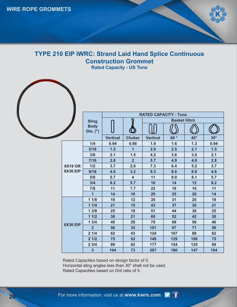
Rated Capacities based on design factor of 5.Horizontal sling angles less than 30° shall not be used.Rated Capacities based on D/d ratio of 5.
For more information, visit us at www.kwrs.com
TYPE 210 EIP IWRC: Strand Laid Hand Splice Continuous Construction Grommet
Rated Capacity - US Tons
26
WIRE ROPE GROMMETS
Vertical Choker Vertical 60 ° 45° 30°1/4 0.94 0.66 1.9 1.6 1.3 0.94
5/16 1.5 1 2.9 2.5 2.1 1.53/8 2.1 1.5 4.2 3.6 3.0 2.1
7/16 2.8 2 5.7 4.9 4.0 2.81/2 3.7 2.6 7.3 6.4 5.2 3.7
9/16 4.6 3.2 9.3 8.0 6.6 4.65/8 5.7 4 11 9.9 8.1 5.73/4 8.2 5.7 16 14 12 8.27/8 11 7.7 22 19 16 111 14 10 29 25 20 14
1 1/8 18 12 35 31 25 181 1/4 21 15 43 37 30 211 3/8 25 18 51 44 36 251 1/2 30 21 60 52 42 301 3/4 40 28 79 69 56 40
2 50 35 101 87 71 502 1/4 62 43 124 107 88 622 1/2 75 52 149 129 106 752 3/4 89 62 177 154 125 89
3 104 73 207 180 147 104
6X19 OR6X36 EIP
6X36 EIP
Sling Body
Dia. (")
RATED CAPACITY - TonsBasket Hitch
For more information, visit us at www.kwrs.com
WIRE ROPE GROMMETS
27
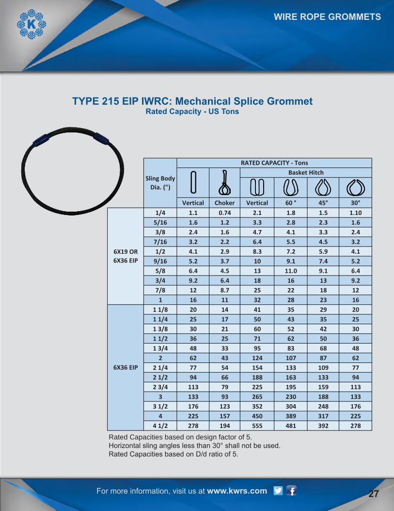
Rated Capacities based on design factor of 5.Horizontal sling angles less than 30° shall not be used.Rated Capacities based on D/d ratio of 5.
TYPE 215 EIP IWRC: Mechanical Splice GrommetRated Capacity - US Tons
Vertical Choker Vertical 60 ° 45° 30°1/4 1.1 0.74 2.1 1.8 1.5 1.10
5/16 1.6 1.2 3.3 2.8 2.3 1.63/8 2.4 1.6 4.7 4.1 3.3 2.4
7/16 3.2 2.2 6.4 5.5 4.5 3.21/2 4.1 2.9 8.3 7.2 5.9 4.1
9/16 5.2 3.7 10 9.1 7.4 5.25/8 6.4 4.5 13 11.0 9.1 6.43/4 9.2 6.4 18 16 13 9.27/8 12 8.7 25 22 18 12
1 16 11 32 28 23 161 1/8 20 14 41 35 29 201 1/4 25 17 50 43 35 251 3/8 30 21 60 52 42 301 1/2 36 25 71 62 50 361 3/4 48 33 95 83 68 48
2 62 43 124 107 87 622 1/4 77 54 154 133 109 772 1/2 94 66 188 163 133 942 3/4 113 79 225 195 159 113
3 133 93 265 230 188 1333 1/2 176 123 352 304 248 176
4 225 157 450 389 317 2254 1/2 278 194 555 481 392 278
6X19 OR6X36 EIP
6X36 EIP
Sling Body Dia. (")
RATED CAPACITY - TonsBasket Hitch

For more information, visit us at www.kwrs.com
Rated Capacities based on design factor of 5.Horizontal sling angles less than 30° shall not be used.Rated Capacities based on D/d ratio of 5.
TYPE 270 EIP IWRC: Cable Laid Hand Splice Continuous Construction Grommet
Rated Capacity - US Tons
WIRE ROPE GROMMETS
28
Vertical Choker Vertical 60° 45° 30°3/4 1/4 5.6 3.6 11 9.7 7.90 5.6
15/16 5/16 8.7 5.6 17 15.0 12 8.71 1/8 3/8 12 8 25 21.0 17 12
1 5/16 7/16 17 11 33 29.0 23 171 1/2 1/2 21 14 43 37.0 30 21
1 11/16 9/16 27 17 53 46.0 38 271 7/8 5/8 33 21 66 57.0 46 332 1/4 3/4 46 30 92 80 65 462 5/8 7/8 62 40 123 107 87 62
3 1 79 51 158 137 112 793 3/8 1 1/8 98 64 196 170 138 983 3/4 1 1/4 119 77 237 205 168 119
6X19 OR6X36 EIP
6X36 EIP
RATED CAPACITY - TONS
Sling Body Dia.
Comp Rope Dia.
Basket Hitch

For more information, visit us at www.kwrs.com 29
CABLE LAID SLINGS
Rated Capacities Basket Hitch based on D/d ratio of 10 times the component rope diameter.Rated Capacities based on pin diameter no larger than natural eye width or less than the nominal sling diameter.Rated Capacities based on design factor of 5.Horizontal sling angles less than 30° shall not be used.
TYPE CL15: Galvanized Cable Laid Single Part SlingRated Capacity - US Tons
Vertical ChokerHitch
AlloyHook
60° 45° 30°1/4 0.50 0.34 1.0 0.87 0.71 0.50 2.0 4 0.88 1.63 13/8 1.1 0.74 2.2 1.9 1.5 1.1 3.0 6 1.13 2.13 1 1/21/2 1.9 1.3 3.7 3.2 2.6 1.9 4.0 8 1.5 2.75 25/8 2.8 1.9 5.5 4.8 3.9 2.8 5.0 10 1.75 3.25 33/4 4.1 2.8 8.1 7.0 5.8 4.1 6.0 12 2.0 3.75 57/8 5.4 3.7 11 9.4 7.6 5.4 7.0 14 2.25 4.25 71 6.9 4.7 14 12 9.7 6.9 8.0 16 2.5 4.50 7
1 1/8 8.3 5.8 17 14 12 8.3 9.0 18 2.88 5.13 111 1/4 9.9 7.0 20 17 14 9.9 10 20 2.88 5.13 11
7X7X7
7X7X19
Rope Dia. (")
Basket Hitch Eye Dimensions (") Thimble Dimensions
A B A B WLL Tons
For more information, visit us at www.kwrs.com
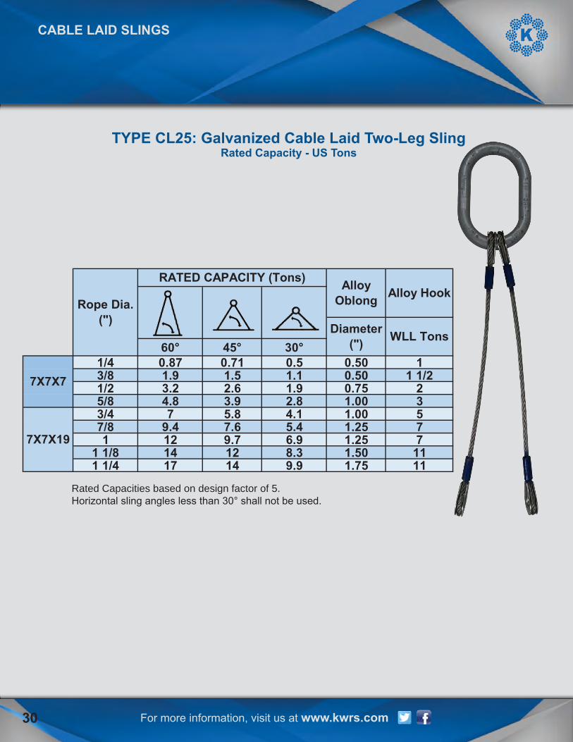
Rated Capacities based on design factor of 5.Horizontal sling angles less than 30° shall not be used.
TYPE CL25: Galvanized Cable Laid Two-Leg SlingRated Capacity - US Tons
CABLE LAID SLINGS
30
60° 45° 30°1/4 0.87 0.71 0.5 0.50 13/8 1.9 1.5 1.1 0.50 1 1/21/2 3.2 2.6 1.9 0.75 25/8 4.8 3.9 2.8 1.00 33/4 7 5.8 4.1 1.00 57/8 9.4 7.6 5.4 1.25 71 12 9.7 6.9 1.25 7
1 1/8 14 12 8.3 1.50 111 1/4 17 14 9.9 1.75 11
Alloy Oblong Alloy Hook
Diameter (") WLL Tons
7X7X7
7X7X19
Rope Dia. (")
RATED CAPACITY (Tons)
For more information, visit us at www.kwrs.com
CABLE LAID SLINGS
31
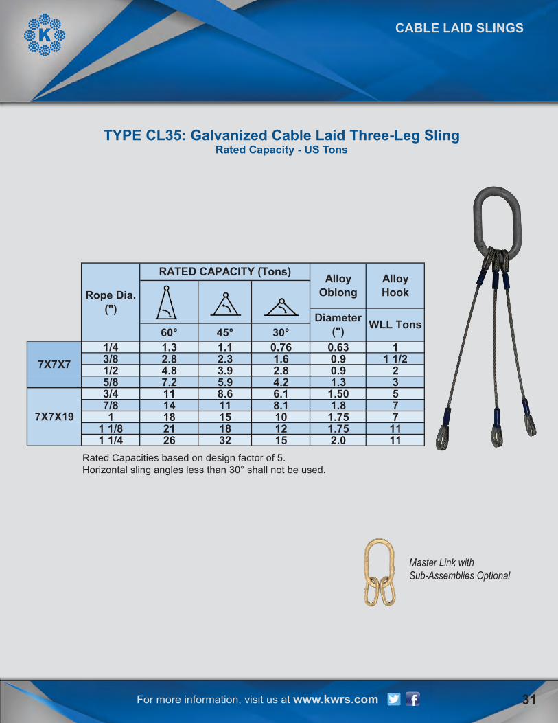
Rated Capacities based on design factor of 5.Horizontal sling angles less than 30° shall not be used.
TYPE CL35: Galvanized Cable Laid Three-Leg SlingRated Capacity - US Tons
Master Link withSub-Assemblies Optional
60° 45° 30°1/4 1.3 1.1 0.76 0.63 13/8 2.8 2.3 1.6 0.9 1 1/21/2 4.8 3.9 2.8 0.9 25/8 7.2 5.9 4.2 1.3 33/4 11 8.6 6.1 1.50 57/8 14 11 8.1 1.8 71 18 15 10 1.75 7
1 1/8 21 18 12 1.75 111 1/4 26 32 15 2.0 11
Alloy Oblong
Alloy Hook
Diameter (") WLL Tons
7X7X7
7X7X19
Rope Dia. (")
RATED CAPACITY (Tons)

For more information, visit us at www.kwrs.com
Rated Capacities based on design factor of 5.Horizontal sling angles less than 30° shall not be used.
TYPE CL45: Galvanized Cable Laid Four-Leg SlingRated Capacity - US Tons
CABLE LAID SLINGS
Master Link withSub-Assemblies Optional
32
60° 45° 30°1/4 1.7 1.4 1 0.75 13/8 3.8 3.1 2.2 0.75 1 1/21/2 6.4 5.2 3.7 1.00 25/8 9.6 7.8 5.5 1.25 33/4 14 11 8.1 1.5 57/8 19 15 11 1.75 71 24 19 14 2 7
1 1/8 29 23 17 2.25 111 1/4 34 28 20 2.50 11
7X7X7
7X7X19
Rope Dia. (")
RATED CAPACITY (Tons) Alloy Oblong Alloy Hook
Diameter (") WLL Tons

For more information, visit us at www.kwrs.com
STAINLESS STEEL SLINGS
33
Rated Capacities Basket Hitch based on D/d ratio of 25 times the component ropediameter.Rated Capacities based on pin diameter no larger than natural eye width or less than thenominal sling diameter.Rated Capacities based on design factor of 5.Horizontal sling angles less than 30° shall not be used.
TYPE SS15 T-304: Stainless Steel SlingRated Capacity - US Tons
Vertical ChokerHitch
AlloyHook
60° 45° 30°1/4 0.61 0.45 1.2 1.1 0.86 0.61 2.0 4 0.88 1.63 15/16 0.86 0.63 1.7 1.5 1.2 0.86 2.5 5 1.06 1.88 13/8 1.1 0.84 2.3 2.0 1.6 1.1 3.0 6 1.13 2.1 1 1/27/16 1.5 1.1 3.1 2.7 2.2 1.5 3.5 7 1.25 2.38 21/2 2.2 1.6 4.3 3.8 3.1 2.2 4.0 8 1.5 2.75 39/16 2.7 2.0 5 4.7 3.8 2.7 4.5 9 1.5 2.75 55/8 3.3 2.5 7 5.8 4.7 3.3 5.0 10 1.75 3.25 53/4 4.7 3.5 9 8.2 6.7 4.7 6.0 12 2.0 3.75 57/8 6.3 4.7 13 11 8.9 6.3 7 14 2.25 4.25 51 8.1 6.0 16 14 11 8 8 16 2.5 4.5 11
1 1/8 10 7.4 20 17 14 10 9 18 2.88 5.13 111 1/4 12 9.1 25 21 17 12 10 20 2.88 5.13 151 3/8 14 11 29 24 20 14 11 22 3.5 6.25 221 1/2 17 13 34 29 24 17 12 24 3.5 6.25 221 3/4 22 17 45 38 31 22 14 28 4.5 9.0 30
2 28 21 57 48 39 28 16 32 6.0 12 372 1/4 35 25 69 57 49 33 18 36 7.0 14 45
6X19 OR
6X36 EIP
6X36 EIP
Rope Dia. (")
Basket Hitch Eye Dimensions (")Thimble
Dimensions(")
A B A B WLL Tons

For more information, visit us at www.kwrs.com
Rated Capacities based on design factor of 5.Horizontal sling angles less than 30° shall not be used.
TYPE SS25 T-304: Two-Leg Stainless Steel SlingRated Capacity - US Tons
34
60° 45° 30°1/4 1.1 0.86 0.61 0.50 1
5/16 1.5 1.2 0.86 0.50 13/8 2 1.6 1.1 0.50 1 1/2
7/16 2.7 2.2 1.5 0.75 21/2 3.8 3.1 2.2 0.75 39/16 4.7 3.8 2.7 0.875 55/8 5.8 4.7 3.3 1.0 53/4 8.2 6.7 4.7 1.0 57/8 11 8.9 6.3 1.25 51 14 11 8 1.50 11
1 1/8 17 14 10 1.50 111 1/4 21 17 12 1.75 151 3/8 24 20 14 1.75 221 1/2 29 24 17 2.0 221 3/4 38 31 22 2.25 30
2 48 39 28 2.5 37
7X7X7
7X7X19
Rope Dia. (")
RATED CAPACITY (Tons) Alloy Oblong
Alloy Hook
Diameter (") WLL Tons
STAINLESS STEEL SLINGS

For more information, visit us at www.kwrs.com 35
Rated Capacities based on design factor of 5.Horizontal sling angles less than 30° shall not be used.
TYPE SS35 T-304: Three Leg Stainless Steel SlingRated Capacity - US Tons
Master Link withSub-Assemblies Optional
60° 45° 30°1/4 1.6 1.3 0.91 0.75 1
5/16 2.2 1.8 1.3 0.75 13/8 3 2.4 1.7 0.875 1 1/2
7/16 4 3.3 2.3 1.0 21/2 5.6 4.6 3.2 1.0 39/16 7.1 5.8 4.1 1.0 55/8 8.6 7.1 5 1.0 53/4 12 10 7.1 1.5 57/8 16 13 9.5 1.75 51 21 17 12 1.75 11
1 1/8 26 21 15 2 111 1/4 31 25 18 2.25 151 3/8 36 30 21 2.5 221 1/2 43 35 25 2.5 221 3/4 57 46 33 2.75 30
Alloy Oblong
Alloy Hook
Diameter (")
WLL Tons
6X19 OR 6X36
6X36
Rope Dia. (")
RATED CAPACITY (Tons)
STAINLESS STEEL SLINGS
For more information, visit us at www.kwrs.com
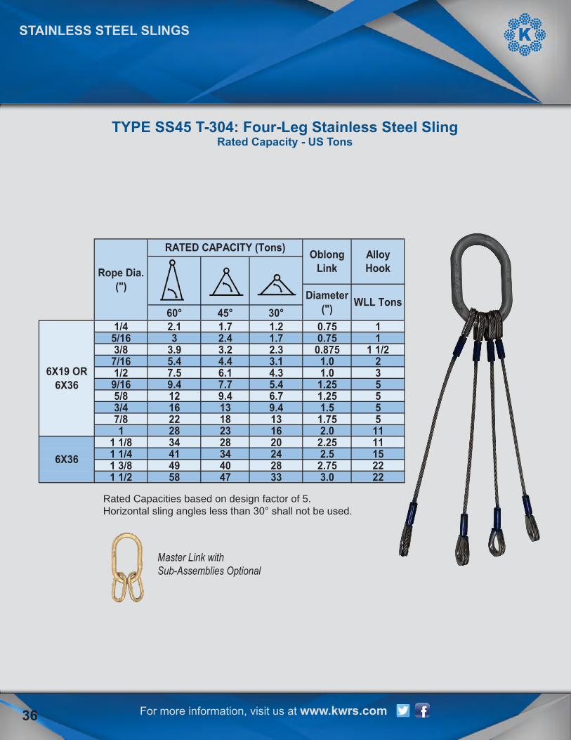
Rated Capacities based on design factor of 5.Horizontal sling angles less than 30° shall not be used.
STAINLESS STEEL SLINGS
TYPE SS45 T-304: Four-Leg Stainless Steel SlingRated Capacity - US Tons
Master Link withSub-Assemblies Optional
36
60° 45° 30°1/4 2.1 1.7 1.2 0.75 1
5/16 3 2.4 1.7 0.75 13/8 3.9 3.2 2.3 0.875 1 1/2
7/16 5.4 4.4 3.1 1.0 21/2 7.5 6.1 4.3 1.0 3
9/16 9.4 7.7 5.4 1.25 55/8 12 9.4 6.7 1.25 53/4 16 13 9.4 1.5 57/8 22 18 13 1.75 51 28 23 16 2.0 11
1 1/8 34 28 20 2.25 111 1/4 41 34 24 2.5 151 3/8 49 40 28 2.75 221 1/2 58 47 33 3.0 22
6X19 OR 6X36
6X36
Rope Dia. (")
RATED CAPACITY (Tons) Oblong Link
Alloy Hook
Diameter (") WLL Tons

For more information, visit us at www.kwrs.com 37
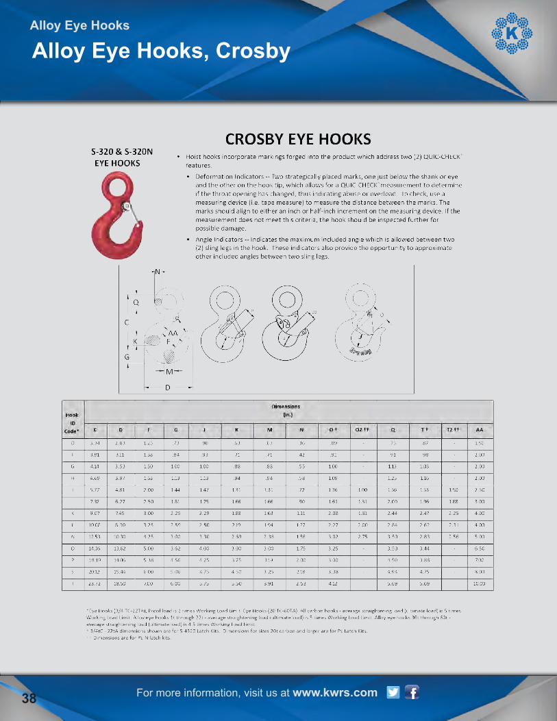
ALLOY EYE HOOKS
Alloy Eye Hooks, Crosby
For more information, visit us at www.kwrs.com
Alloy Eye Hooks
Alloy Eye Hooks, Crosby
38

For more information, visit us at www.kwrs.com
Notes
39

BE SURE TO FOLLOW US AT: WWW.KWRS.COM
CORPUS CHRISTI302 Flato Road
Corpus Christi, TX 78405361-289-1444800-289-1445
Fax: 361-289-7555
SAN ANTONIO4202 Dividend Drive
San Antonio, TX 78219210-527-0555877-527-0555
Fax: 210-527-9701
HOUSTON5600 Surrey SquareHouston, TX 77017
713-673-7881800-392-5510
Fax: 713-673-2901
AFFILIATES