Embed Size (px)
Citation preview
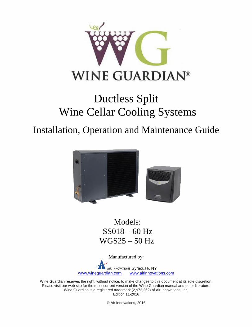
Ductless Split
Wine Cellar Cooling Systems
Installation, Operation and Maintenance Guide
Models:
SS018 – 60 Hz
WGS25 – 50 Hz
Manufactured by:
Syracuse, NY www.wineguardian.com www.airinnovations.com
Wine Guardian reserves the right, without notice, to make changes to this document at its sole discretion. Please visit our web site for the most current version of the Wine Guardian manual and other literature.
Wine Guardian is a registered trademark (2,972,262) of Air Innovations, Inc. Edition 11-2016
© Air Innovations, 2016
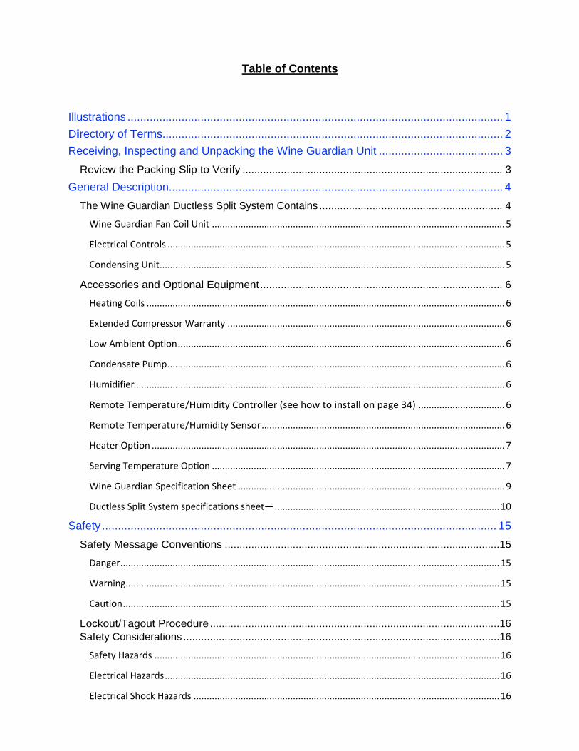
Table of Contents
Illustrations ...................................................................................................................... 1
Directory of Terms........................................................................................................... 2
Receiving, Inspecting and Unpacking the Wine Guardian Unit ....................................... 3
Review the Packing Slip to Verify ........................................................................................ 3
General Description......................................................................................................... 4
The Wine Guardian Ductless Split System Contains .............................................................. 4
Wine Guardian Fan Coil Unit ................................................................................................................ 5
Electrical Controls ................................................................................................................................. 5
Condensing Unit .................................................................................................................................... 5
Accessories and Optional Equipment .................................................................................. 6
Heating Coils ......................................................................................................................................... 6
Extended Compressor Warranty .......................................................................................................... 6
Low Ambient Option ............................................................................................................................. 6
Condensate Pump ................................................................................................................................. 6
Humidifier ............................................................................................................................................. 6
Remote Temperature/Humidity Controller (see how to install on page 34) ................................. 6
Remote Temperature/Humidity Sensor ............................................................................................. 6
Heater Option ....................................................................................................................................... 7
Serving Temperature Option ................................................................................................................ 7
Wine Guardian Specification Sheet ...................................................................................................... 9
Ductless Split System specifications sheet— ...................................................................................... 10
Safety ............................................................................................................................ 15
Safety Message Conventions .............................................................................................15
Danger ................................................................................................................................................. 15
Warning............................................................................................................................................... 15
Caution ................................................................................................................................................ 15
Lockout/Tagout Procedure ..................................................................................................16
Safety Considerations ...........................................................................................................16
Safety Hazards .................................................................................................................................... 16
Electrical Hazards ................................................................................................................................ 16
Electrical Shock Hazards ..................................................................................................................... 16
Hot Parts Hazards ............................................................................................................................... 16
Moving Parts Hazards ......................................................................................................................... 16
Equipment Safety Interlocks ..................................................................................................17
Main Power Switch ................................................................................................................17
Installation ..................................................................................................................... 19
Pre-installation Test ..............................................................................................................19
Air Flow Diagram ..................................................................................................................19
Installing the Fan Coil Unit ............................................................................................ 21
Planning the fan coil installation ............................................................................................21
Mounting the System ............................................................................................................23
Installing the Condensate Drain Connection ................................................................. 25
Installing the Drain Line .........................................................................................................25
Priming the Drain ..................................................................................................................25
Wiring the Fan Coil Unit for Power ................................................................................ 26
Installing the Condensing Unit ....................................................................................... 27
Installation of Interconnecting Refrigerant Lines (Suction and Liquid) ...................................27
Split System Interconnecting Line Sizing Chart ................................................................................... 28
Sample Piping Configurations ...............................................................................................29
Leak Checking and Evacuation Process ...............................................................................30
Wiring .................................................................................................................................................. 30
Refrigerant Charging – for low ambient models only ......................................................................... 31
Determining the amount of charge .................................................................................................... 31
Procedures for Charging System with Low Ambient Option (Head Pressure Control) ...........31
Superheat ............................................................................................................................................ 33
Sub-Cooling ......................................................................................................................................... 33
Split System Operations Chart ............................................................................................................ 34
Installing the Thermostat and Communication Cable .................................................... 35
Mounting the Remote Interface Controller – Optional Feature ...............................................35
Installing the Wine Guardian Remote Sensor – Optional Feature ..........................................37
Mounting the Remote Sensor ................................................................................................37
Joining the Communication Cable ................................................................................. 39
Changing Jumper Positions ..................................................................................................39
Standard Controller Functions ....................................................................................... 40
Inspection and Start Up Checklists ............................................................................... 46
Receiving and Inspecting ......................................................................................................46
Handling and Installing ..........................................................................................................46
Starting-up the Unit ...............................................................................................................46
Starting-up and Operating the Wine Guardian Split System ......................................... 47
Turn on the Unit ....................................................................................................................47
Testing the Fan .....................................................................................................................47
Running the Unit ..................................................................................................................47
Setting the Local User Interface Controller ............................................................................48
Regulating the Wine Cellar Temperature ..............................................................................48
Maintenance .................................................................................................................. 49
General ................................................................................................................................49
Cleaning the Condensate Drain System ................................................................................50
Cleaning the Humidifier .........................................................................................................50
Heating Coil Option ...............................................................................................................50
Maintenance Schedule ................................................................................................ 51
Monthly .................................................................................................................................51
Yearly....................................................................................................................................51
Troubleshooting ........................................................................................................... 52
Typical start up problems ................................................................................................................. 52
Unit does not start up ....................................................................................................................... 52
Power switch light is on and the remote interface controller light is off ........................................... 52
Power switch light is on and the remote interface controller light is on ........................................... 52
Unit is operating and blows evaporator air, .................................................................................... 53
Cellar temperature too cold (below 51 degrees) when unit is running ............................................. 53
Cellar temperature too cold (below 51 degrees) when unit is not running ....................................... 53
Humidity too low or supply air is too cold, without optional humidifier ........................................... 53
Humidity too low, without optional humidifier .................................................................................. 54
Humidity too low, with optional humidifier ....................................................................................... 54
Humidity too high when unit is running but not cooling .................................................................... 54
Humidity too high when unit is not running ....................................................................................... 54
Humidity too high when unit is running and cooling.......................................................................... 54
Unit operates but the power switch light is not ON ........................................................................... 55
Unit is leaking water ........................................................................................................................... 55
Unit is running properly, but the sound of the unit objectionable .................................................... 55
High Pressure Switch has Shut the Unit Down ..................................................................55
Advanced Troubleshooting ............................................................................................ 56
Evaporator Coil is Freezing ................................................................................................................. 56
High pressure switch keeps tripping ................................................................................................... 56
Unit cycles on and off more than 8 times/hr ...................................................................................... 56
High pitched or loud rubbing noise, clanking or vibration ................................................................. 56
Replacing the blowers ......................................................................................................................... 56
Contact and Warranty Information ................................................................................ 57
Contact Information ...............................................................................................................57
Warranty and Warranty Procedure .....................................................................................57
Manufacturer’s Warranty – U.S. and Canada Only ................................................... 58
1
Illustrations
Overview of fan coil and condensing unit .................................................................... ….8
Wine Guardian specification sheet ....................................................................................... 9
Refrigeration Illustration ........................................................................................................10
Ductless Dimensional drawings for models SS018 & WGS25 .............................................11
Wiring diagram for model SS018 ..........................................................................................12
Wiring diagram for model WGS025 ......................................................................................13
Wiring diagram for models SS018 & WGS25 condensing unit ............................................14
2
Directory of Terms
Ambient Air – The surrounding area outside the wine cellar such as a room, basement, garage or
outdoors.
BTU/H – British thermal units/hour. A unit of measurement to describe the power of heating and
cooling system.
CFM – Cubic feet per minute. A unit of measurement for the amount of air handled by the fan.
Condensate / Condensation – The water formed out of the air when it is cooled below a certain
temperature (called dew point). Often referred to as “sweating” on pipes and cold surfaces. This water
collects at the bottom of the evaporator or cooling coil and drains out of the unit through the drain
line.
Condensing Unit (Heat Rejection) – The condensing unit uses the compressor, condenser coil and
fan to remove heat from the refrigerant to the ambient air outside the wine cellar. The word condenser
refers to the condensation of the refrigerant from gas to liquid phase.
CSA/ETL – Canadian Standards Association/Edison Testing Laboratory (product compliance to safety standards)
F – (Degrees) Fahrenheit
Fan Coil Unit (Evaporator Cooling) – The fan coil unit uses the cooling coil and the fan to remove
heat from the air inside the wine cellar to the refrigerant, cooling the air and condensing moisture out
of the air. The word evaporator refers to the evaporation of the refrigerant from liquid to gas phase in
the coil. The fan coil unit is ducted to or can be placed inside the wine cellar.
Grille or Diffuser – Inlet or outlet plates to direct the airflow or protect the inside of the unit.
Heat Gain / Loss – The amount of cooling or heating expressed in BTUH and watts transferred
between the wine cellar and the ambient space. The Wine Guardian must offset this heat/gain loss.
Inlet Air – The air returning from the wine room to the Wine Guardian fan coil.
I.D. – Inside diameter
NEC – National Electrical Code
O.D. – Outside diameter
Psig– Pounds force per square inch gauge pressure
Recovery – The amount of cooling the unit does to return the cellar to its set point temperature after
some new heat load is introduced, such as people or new cases of warm wine entering the cellar.
Return Air - The air leaving the cellar and returning to the inlet of the fan coil. (See Inlet Air above)
TXV – Thermal expansion valve
VAC – Volts alternating current
SP – Static pressure. Unit of measurement (inches of water column) of the pressure of the air handled
by the fan.
Set Point – The desired temperature or humidity set on the remote interface controller or humidistat.
Supply Air - The air entering the wine cellar from the discharge of the fan coil.
3
Receiving, Inspecting and Unpacking the Wine Guardian Unit
NOTE: Wine Guardian units are factory assembled and tested prior to shipment. The Wine Guardian Ductless Split System consists of two separate components, the Wine Guardian fan coil and condensing unit.
Each Wine Guardian component is shipped in a corrugated box. A shipment may include one or
more boxes containing accessories.
Lift at the designated handhold locations only or fully support from underneath.
Before opening, inspect the packing crates or boxes for obvious signs of damage or
mishandling.
Write any discrepancy or visual damage on the bill of lading before signing.
Inspect all equipment for any sign of damage caused during transit.
Report all visual or concealed damage to the carrier and file a claim immediately.
Thoroughly inspect the contents for any visible damage or loose parts.
Review the Packing Slip to Verify
Model number
Factory installed options
Unit accessories
If any items listed on the packing slip do not match your order information, contact the place of purchase
immediately.
IMPORTANT If this procedure is not followed, the shipping company may reject the claim and the
consignee may suffer the loss. Do not return the shipment to the factory.
4
General Description
The Wine Guardian cooling unit is a professional grade, American-manufactured, split two-piece
climate control unit designed specifically for the storage of wine at cellar temperatures. It is designed
for easy installation and operation. Wine Guardian uses digital electronic controls and R-134a
refrigerant. The entire Wine Guardian system is tested at the factory. All components are of a high
quality standard commercial grade.
The system is approved by ETL according to UL 1995 and CSA safety standards. All wiring complies
with NEC. Each Wine Guardian fan coil section is furnished with a sealed, UL-approved power cord
and plug.
All Wine Guardian 50Hz units carry the CE mark. Each unit is furnished with a sealed, CE- approved
power cord and plug.
The Wine Guardian Ductless Split System Contains
1. A Wine Guardian Fan Coil Unit with:
A thermal expansion valve to control the flow of refrigerant into the evaporator coil
An external condensate drain line. No external trap is required.
A removable control panel for ease of service
1a. Optional
Optional: Remote interface controller and control cable
2. A Condensing Unit with:
A filer dryer to keep the refrigerant clean and free of contaminants
A sight glass to observe the level of refrigerant
A manual reset high pressure switch on the discharge to protect the compressor from high
pressures.
Auto reset low pressure switch
24-volt contactor for control of fan coil unit
Oversize receiver
Service valves
Outdoor enclosure
2a. Included with Low Ambient Option
Crankcase heater
LAC valve
Outdoor enclosure
5
Wine Guardian Fan Coil Unit The Wine Guardian fan coil unit meets its rated capacities for total BTU/H and CFM (watts and M3/h
for 50Hz) at design cellar conditions and external static pressures. The fan is a motorized impeller
type, statically and dynamically balanced, and uses permanently lubricated direct drive motors
requiring no maintenance.
The Wine Guardian fan coil section operates as air passes through the sides of the decorative front
panel and through the cooling coil where it is cooled by the refrigerant inside the coil. This causes any
excess humidity in the air to condense and be captured in the drain pan and piped outside the unit. Air
is then pressurized and discharged out of the unit through the top screened section. Optional heating
coils are located between the cooling coil and the fan. These coils heat the air to prevent low
temperatures within the cellar.
All exterior framing of the Wine Guardian is powder coated 0.063-inch gauge aluminum to prevent
rust and corrosion. All coils are aluminum tubes, aluminum fins, to prevent premature corrosion.
Each unit is provided with a pre-wired and tested local user interface controller mounted on the chassis
within the Wine guardian unit. The user interface controller has multiple control functions for cooling,
heating and humidification. It has a fully automatic mode to switch between heating and cooling.
Electrical Controls
The main electrical control board and components are located on a separate panel, internal to the chassis. All
wiring is in accordance with the NEC. Wires are numbered and color coded to match the wiring
diagrams.
Electric power is supplied by a single factory-furnished cord and plug. All external controls are digital
and proprietary to Wine Guardian products. Only approved communication cable and Wine Guardian
controllers are suitable for proper system operation.
Condensing Unit Compressors are rotary, self-lubricating, permanently sealed, hermetic reciprocating-type compressors,
with internal overload protection and capacitor start. They include a minimum of 24 months’
manufacturer’s warranty and an optional five-year warranty. Compressors are mounted on rubber-in-
shear isolators to reduce noise and vibration. Additional features include a liquid line filter drier,
Sporlan Head Master Controls, a liquid line receiver and refrigerant sight glass. Each unit is housed in
a painted aluminum enclosure suitable for outdoor installation. The outdoor enclosure has adequate
area for ventilation and refrigerant piping penetrations.
IMPORTANT The air exhaust from the condensing unit is hot and will be 25°F to 35°F or 15°C to 20°C above the
entering temperature. The condensing units are rated for a maximum temperature of 115°F (46°C).
The condensing units should be installed in a well-ventilated area to ensure proper air flow across the condenser coil and to limit short cycling.
6
Accessories and Optional Equipment
Heating Coils An optional heating coil is built in and requires no additional power source. The electric
heating option is factory installed and includes primary and secondary over-temperature
protection devices per UL and NEC.
Extended Compressor Warranty The Wine Guardian uses only the best commercially available compressors on the market.
However, since the compressor is the single most expensive component in the unit, it is
recommended that you purchase the extended warranty option.
Low Ambient Option A factory-installed low ambient option is available that makes the Wine Guardian capable of
exposure to low ambient temperatures. This feature maintains system pressures to prevent
freezing the cooling coil and heats the compressor oil reservoir. The low ambient option is
recommended whenever the condenser section is exposed to air temperatures below 40°F (4°C).
Condensate Pump An optional Wine Guardian automatic condensate pump is available to pump the water to a
remote sink, drain pipe or outside. It requires a separate 120-volt electrical outlet. 50Hz models
require a separate 220/240-volt electrical outlet.
Humidifier Another popular option for the Wine Guardian is the Standalone humidifier. The humidifier is
sold and installed as a standalone system. Each humidifier is furnished with a communication
cable connection to plug into the Wine Guardian fan coil unit. It is then controlled by the same
user interface controller that is used for the operation of the Wine Guardian unit. The
humidifier requires a water supply and drain for operation.
Remote Temperature/Humidity Controller (see how to install on page 34) The remote temperature/humidity controller (Remote Interface Controller) is intended to provide
a means for user interface at a remote location. The controller can be used as a remote
sensor/controller mounted within the wine cellar remote from the Ductless Split System. The
controller can also be used as a remote indicator (without sensor) mounted directly outside of the
wine cellar of the residence or building. The Remote Interface Controller includes a backlit face
for temperature and humidity indication along with controller set-up and operational functions.
Remote Temperature/Humidity Sensor The remote temperature/humidity sensor is intended to provide a means of sensing one or more
locations within the wine cellar and designed to work in conjunction with the Remote Interface
Controller or Local Interface Controller integral to the Wine Guardian Ductless Split System.
Multiple sensor readings are averaged and controlled to a single point. The sensors do not have
any temperature or humidity indication and must be mounted within the wine cellar.
7
Heater Option The electric heat option includes an integral electric heating element, thermal overload protection
device and controls. The Wine Guardian will either cool or heat the air, but it is not designed to
do both at the same time.
Serving Temperature Option The serving-temperature option allows a Wine Guardian unit to control to an extended
temperature range from 42° F to 64° F (5°C - 18°C). The serving temperature option consists of a
cooling coil mounted temperature sensor and control to prevent freeze up of the coil during low
temperature operation.
CAUTION
CAREFULLY FOLLOW THE INSTALLATION INSTRUCTIONS INCLUDED WITH THE HUMIDIFIER. REFER TO THE INSTRUCTIONS CONTAINED IN THE BOX FOR THE HUMIDISTAT.
8
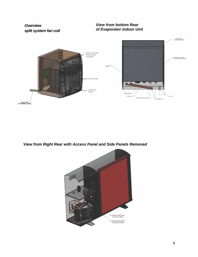
Overview of Ductless
split system fan coil
View from Right Rear with Access Panel and Side Panels Removed
View from bottom Rear of Evaporator Indoor Unit
SUPPLY AIR WIH ADJUSTABLE LOUVERS
RETURN AIR CONTROL PANEL
SS018 WGS25
Total/Sensible @115V Total/Sensible @220-240V
2870/2300 BTUH 810/650 Watts
2580/2050 BTUH 730/570 Watts
2860/2230 BTUH 780/625 Watts
2870/2260 BTUH 785/620 Watts
2800/2220 BTUH 760/61 Watts
2600/2100 BTUH 680/520 Watts
2300/1800 BTUH 610/470 Watts
Fan-coil Section Rated Watts Rated Watts
75 Rated Watts 85 Rated Watts
150 CFM 240 M3h
Electic Electric1000/3400 BTUH 1000/3400 Watts
0.42 lbs/hr 1.19 kg/hr
0.97 lbs/hr 1.44 kg/hr
1.11 lbs/hr 1.5 kg/hr
115 Volt /1 phase /60Hz 220-240Volts /1 phase / 50Hz
0.7 Amps 0.4 Amps
5.05 Amps 2.3 Amps
6.2 Amps 3.3 Amps
0.3 Amps 0.3 Amps
25 lbs 11.3 kg
13.31 inches 33.80 cm
14.25 inches 36.20 cm15.87 inches 40.30 cm
0.5 inches 12.7 mm
SS018 Cond WGS25 Cond
1/4 HP 1/2 HP
75 Watts 68 Watts
350 CFM 510 M3h
75 lbs 34 kg
Aluminum Aluminum
Powder-coated Powder-coated
9.0 inches 22.86 cm
34.0 inches 86.36 cm
25.12 inches 63.80 cm
208-230 Volts /1 Phase /60Hz 220-240 Volts /1 Phase /50Hz
3.3 Amps 3.43 Amps
6 Amps 7 Amps
ETLc CE
Minimum Circuit Size (w/heat option)
Finish
Weight
Length
1. Net cooling capacity at entering temperature and humidity conditions of 57 Deg F (14 Deg C) and 55% RH at rated airflow. Reduce capacity by 3% for each 10% reduction in
evaporator airflow.
Power
MCA
MOP
2. Wine Guardian reserves the right to make changes to this document without prior notice at its sole discretion.
Agency Approval(s)
Nominal Compressor
Fan Motor Size
Rated Air Flow (free blow)
Weight
Construction
Finish
800-825-3268 | 315-452-7420 | Fax 315-452-7420 | www.wineguardian.com | [email protected]
3. All ratings at sea level. REV. 10-2016
WidthHeight
Condensate Drain
7000 Performance Drive | North Syracuse, New York 13212 USA
Width
Height
Condensing Unit
Capacity - water temp of 60 Deg F (15 Deg C)
Capacity - water temp of 90 Deg F (32 Deg C)
Capacity - water temp of 120 Deg F (49 Deg C)
Length
Type
Temperature Accuracy/RH% Accuracy
Type
Power
Current Draw - Cooling mode
Fan coil construction
Current Draw - Heating mode
Enclosure
Performance
Model Number
@10 Deg F (minus 12 Deg C) condenser inlet air
@10 Deg F (4 Deg C) condenser inlet air
@60 Deg F (15 Deg C) condenser inlet air
@70 Deg F (21 Deg C) condenser inlet air
Optional Humidifier
Ductless Split System - 60Hz and 50Hz
Room mounted non-programmable combination thermostat humidistat
+/- 1 Deg F / +/- 10% RH
@100 Deg F (32 Deg C) condenser inlet air
@115 Deg F (46 Deg C) condenser inlet air
Type
@80 Deg F (27 Deg C) condenser inlet air
Fan Motor Size
Rated Air Flow (free blow)
Net Cooling * Total Sensible
Removeable drip pad with integral fan
Electrical Requirements
Electrical Requirements
Controls
Humidifier (Option)
Heat (Option)
Capacity
Aluminum
Black - textured epoxy powder coat
Cabinet
10
Refrigeration Illustration of the System
11
Ductless dimensional drawing for models SS018 and WGS25
12
Wiring diagram for SS018
13
Wiring diagram for WGS25
Fig.5
14
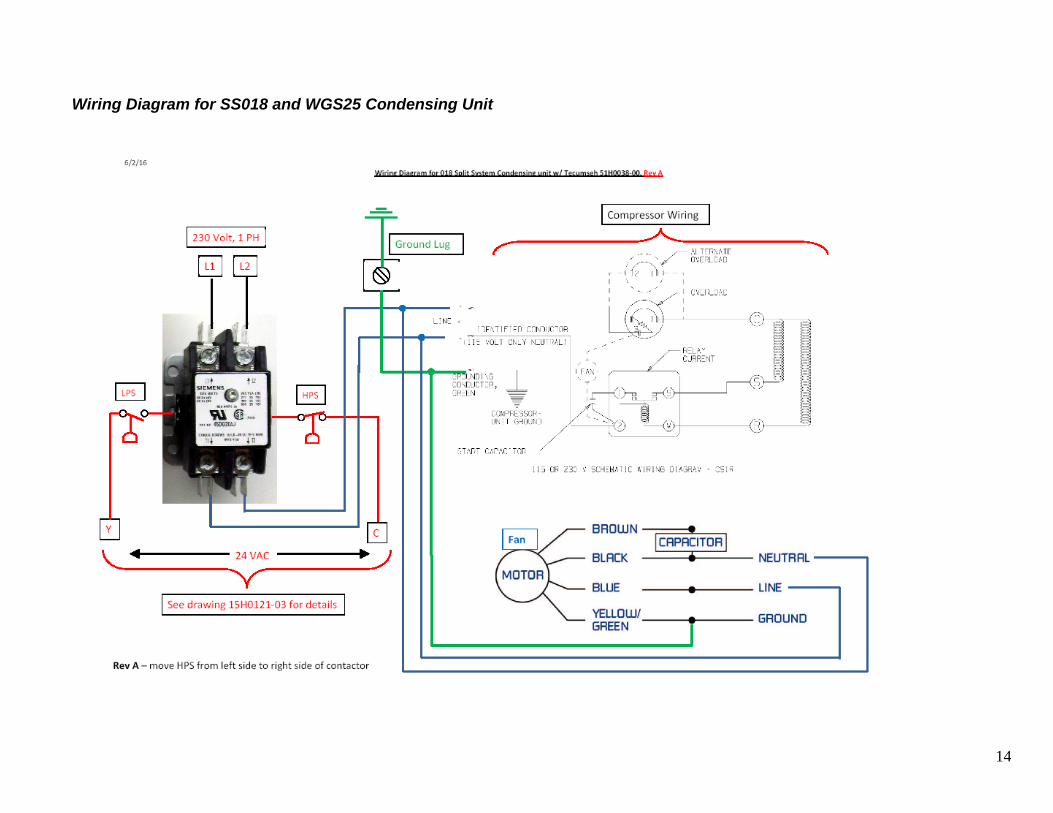
Wiring Diagram for SS018 and WGS25 Condensing Unit
15
Safety
Safety Message Conventions
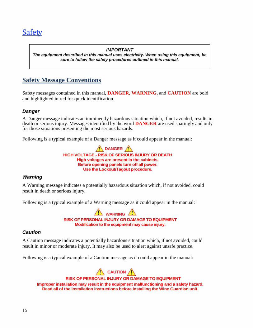
Safety messages contained in this manual, DANGER, WARNING, and CAUTION are bold
and highlighted in red for quick identification.
Danger
A Danger message indicates an imminently hazardous situation which, if not avoided, results in death or serious injury. Messages identified by the word DANGER are used sparingly and only for those situations presenting the most serious hazards.
Following is a typical example of a Danger message as it could appear in the manual:
DANGER HIGH VOLTAGE - RISK OF SERIOUS INJURY OR DEATH
High voltages are present in the cabinets. Before opening panels turn off all power.
Use the Lockout/Tagout procedure.
Warning
A Warning message indicates a potentially hazardous situation which, if not avoided, could
result in death or serious injury.
Following is a typical example of a Warning message as it could appear in the manual:
WARNING
RISK OF PERSONAL INJURY OR DAMAGE TO EQUIPMENT Modification to the equipment may cause injury.
Caution
A Caution message indicates a potentially hazardous situation which, if not avoided, could
result in minor or moderate injury. It may also be used to alert against unsafe practice.
Following is a typical example of a Caution message as it could appear in the manual:
CAUTION
RISK OF PERSONAL INJURY OR DAMAGE TO EQUIPMENT
Improper installation may result in the equipment malfunctioning and a safety hazard. Read all of the installation instructions before installing the Wine Guardian unit.
IMPORTANT The equipment described in this manual uses electricity. When using this equipment, be
sure to follow the safety procedures outlined in this manual.
16
Lockout/Tagout Procedure
1) Turn off the power switch (indicator light should be off)
2) Unplug the unit from the electrical outlet and cover the outlet to prevent
accidently plugging in the unit.
3) Turn off circuit breaker or disconnect switch at condensing unit.
Safety Considerations
The equipment covered by this manual is designed for safe and reliable operation when installed
and operated within its designed specifications. To avoid personal injury or damage to equipment
or property when installing or operating this equipment, it is essential that qualified, experienced
personnel perform these functions using good judgment and safe practices. See the following
cautionary statements.
Safety Hazards Exposure to safety hazards is limited to maintenance personnel working in and around the unit.
When performing maintenance, always use the Lockout/Tagout procedure, which is described in
this chapter. Observe the maintenance safety guidelines in this manual.
Electrical Hazards Working on the equipment may involve exposure to dangerously high voltage. Make sure you are
aware of the level of electrical hazard when working on the system. Observe all electrical warning
labels on the unit.
Electrical Shock Hazards All power must be disconnected prior to installation and servicing this equipment. More than one source of power may be present. Disconnect all power sources to avoid electrocution or shock injuries. Hot Parts Hazards Electric resistance heating elements must be disconnected prior to servicing. Electric heaters may start automatically. Disconnect all power and control circuits prior to servicing the unit to avoid burns. Moving Parts Hazards The Motor and Blower must be disconnected prior to opening access panels. The motor can start
automatically. Disconnect all power and control circuits prior to servicing to avoid serious
injuries or possible dismemberment.
The fans are free-wheeling after the power is disconnected. Allow the fans to stop completely
before servicing the unit to avoid cuts or dismemberment.
IMPORTANT
Installation and maintenance of this equipment is to be performed only by qualified personnel who are familiar with local codes and regulations, and are experienced with this
type of equipment.
17
Rotating Fan Blades are present in the Wine Guardian unit. Sticking a hand into an exposed fan
while under power could result in serious injury. Be sure to use the Lockout/Tagout procedure
when working in this area or remove the power cord.
Equipment Safety Interlocks
There are no electrical safety lockouts installed within the unit. The power cord attached to the
control box must be disconnected from the power sources prior to working on any part of the
electrical system.
Main Power Switch The main power switch is located on the front user interface of the Wine Guardian unit. It shuts off the power to the fan coil unit. A separate disconnect switch will be wired to the condensing unit. Both switches must be turned off prior to servicing equipment.
Energy Type Electrical
Hazard ....................................Electrocution, electrical burns and shock
Magnitude ..............................120 Volts and 230 volts / 1phase / 60Hz (SS018 model)
220-240 volts / 1 phase / 50Hz (WGS25 model)
Control Method ......................Disconnect power cord and On/Off switch
DANGER
Never reach into a unit while the fan is running.
Never open an access door to a fan while the fan is running.
Disconnect the power cord switch before working on the unit. The unit may have more
than one power source to disconnect.
Avoid risk of fire or electric shock. Do not expose the unit to rain or moisture.
WARNING
Check weights to be sure that the rigging equipment can support and move the Wine
Guardian unit safely. Note any specific rigging and installation instructions located in the
Installation section of this manual.
All supports for the unit must be capable of safely supporting the equipment’s weight and
any additional live or dead loads encountered.
All supports for the unit must be designed to meet applicable local codes and
ordinances.
Do not remove access panels until fan impellers have completely stopped. Pressure
developed by moving impellers can cause excessive force against the access
panels.
Fan impellers continue to turn (free-wheel) after the power is shut off.
18
CAUTION
Clean only with a dry cloth.
Never pressurize equipment above specified test pressure. See Wine Guardian
Specification sheet on page 10.
Do not use the Wine Guardian near water.
Do not block any supply or return air openings. Install in accordance with the
instructions in this manual. Do not defeat the safety purpose of the polarized or
grounding type plug. A polarized plug has two blades with one wider than the
other. A grounding type plug has two blades and a third grounding prong. The
wide blade or the third prong is provided for your safety. If the provided plug does
not fit into your outlet, consult an electrician for replacement of the obsolete
outlet.
Protect the power cord from being walked on or pinched, particularly at the outlet
plugs, convenience receptacles, and the point where it exits the unit.
Only use attachments/accessories specified by the manufacturer.
Always operate this equipment from a 120/230 volts 1 phase, 60Hz power sources
only. (220/240 volts / 1 phase/ 50Hz models)
Always ground the outlet to provide adequate protection against voltage surges
and built-up static charges.
Refer all servicing to qualified service personnel. Servicing is required when the
unit has been damaged in any way.
19
Installation
CAUTION SHARP EDGES
RISK OF SERIOUS INJURY
Sharp edges are present inside the Wine Guardian system.
Pre-installation Test
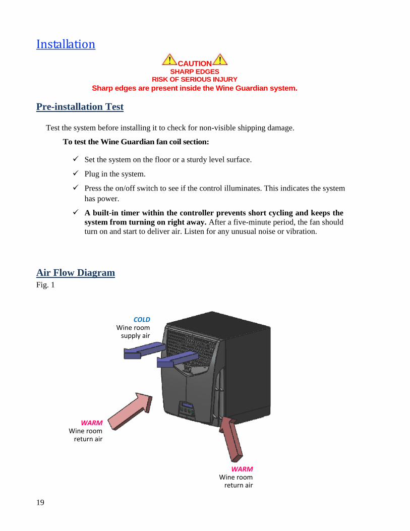
Test the system before installing it to check for non-visible shipping damage.
To test the Wine Guardian fan coil section:
Set the system on the floor or a sturdy level surface.
Plug in the system.
Press the on/off switch to see if the control illuminates. This indicates the system
has power.
A built-in timer within the controller prevents short cycling and keeps the
system from turning on right away. After a five-minute period, the fan should
turn on and start to deliver air. Listen for any unusual noise or vibration.
Air Flow Diagram
Fig. 1
COLD Wine room
supply air
WARM Wine room
return air
WARM Wine room
return air
20
WARNING
RISK OF PERSONAL INJURY OR DAMAGE TO EQUIPMENT
Modification to the equipment may cause injury or damage to the equipment.
DANGER
This equipment is heavy. Place the unit on the floor or on a level and stable
surface that can support the full weight of the unit.
Do not modify the equipment. Modifications may cause damage to the
equipment and will void the warranty.
Never place anything on top of the unit.
Never block or cover any of the openings or outlets to the unit.
Never allow anything to rest on or roll over the power cord.
Never place the unit where the power cord is subject to wear or abuse.
Do not use extension cords.
Never overload wall outlets.
Do not remove or open any cover unless the unit is turned off and the power
cord is plugged in.
Use only dedicated power outlet boxes of the correct capacity and
configuration for the unit model.
CAUTION
RISK OF PERSONAL INJURY OR DAMAGE TO EQUIPMENT
Improper installation may result in the equipment malfunctioning and a safety hazard. Read all the installation instructions before installing the Wine Guardian unit.
21
Installing the Fan Coil Unit
Wine Guardian fan coil units can be installed through-the-wall of the wine cellar or surface mounted
on the wall within the cellar.
Provide ample clearance around the unit to access for unit maintenance.
The fan coil unit can be located either above, or below the condensing unit in height. Wine Guardian
strongly suggests that any height difference be kept to a minimum.
The fan coil unit is equipped with an On/Off switch, two communication ports, and an optional
humidifier connection. Communication ports can be used for other factory options, such as remote
temperature/humidity sensors.
Planning the fan coil installation
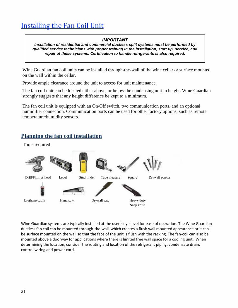
Tools required
Wine Guardian systems are typically installed at the user’s eye level for ease of operation. The Wine Guardian ductless fan coil can be mounted through-the-wall, which creates a flush wall mounted appearance or it can be surface mounted on the wall so that the face of the unit is flush with the racking. The fan-coil can also be mounted above a doorway for applications where there is limited free wall space for a cooling unit. When determining the location, consider the routing and location of the refrigerant piping, condensate drain, control wiring and power cord.
Drill/Phillips head Level Stud finder Tape measure Square Drywall screws
Urethane caulk Hand saw Drywall saw Heavy duty
snap knife
IMPORTANT Installation of residential and commercial ductless split systems must be performed by
qualified service technicians with proper training in the installation, start up, service, and repair of these systems. Certification to handle refrigerants is also required.
22
Where to locate the unit? Location is usually predicated by the racking that can be
reached for control panel access.
How to mount the unit? Use the Wine Guardian supplied sleeve for through-the-wall
installation and our surface mount bracket for surface mount installations.
Locate the electrical power outlet close to the unit in the cellar. Do not use an
extension cord!
Where to run the refrigerant lines? Maximum line length is 50’ with a maximum
elevation rise of 30’. Minimize 90-degree bends and keep condensing unit as close to
fan coil as possible.
Where to locate the thermostat, if remote interface control is ordered? Thermostat
should be located midpoint on a wall within the wine cellar and provide sufficient
access and exposure to airflow.
How to install the drain line? Run to an open floor drain, container, or condensate
pump.
Are all the parts here to complete the installation? Installation sleeve, gasket, sealant
fasteners, surface mount bracket.
IMPORTANT The back side of the fan-coil unit may become unsightly with connections for refrigerant piping, primary power, control wiring and condensate drain. Consideration should be given to unit placement adjacent to finished walls when considering a Through-the-wall installation. The back side of the unit may need to be hidden or an access panel provided for a finished appearance.
23
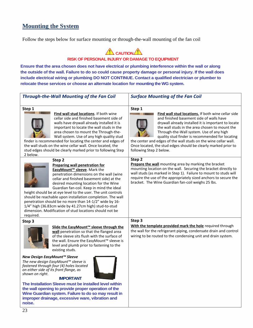
Mounting the System
Follow the steps below for surface mounting or through-the-wall mounting of the fan coil
CAUTION
RISK OF PERSONAL INJURY OR DAMAGE TO EQUIPMENT
Ensure that the area chosen does not have electrical or plumbing interference within the wall or along
the outside of the wall. Failure to do so could cause property damage or personal injury. If the wall does
include electrical wiring or plumbing DO NOT CONTINUE. Contact a qualified electrician or plumber to
relocate these services or choose an alternate location for mounting the WG system.
Through-the-Wall Mounting of the Fan Coil
Surface Mounting of the Fan Coil
Step 1 Find wall stud locations. If both wine cellar side and finished basement side of walls have drywall already installed it is important to locate the wall studs in the area chosen to mount the Through-the-Wall system. Use of any high quality stud
finder is recommended for locating the center and edges of the wall studs on the wine cellar wall. Once located, the stud edges should be clearly marked prior to following Step 2 below.
Step 1 Find wall stud locations. If both wine cellar side and finished basement side of walls have drywall already installed it is important to locate the wall studs in the area chosen to mount the Through-the-Wall system. Use of any high quality stud finder is recommended for locating
the center and edges of the wall studs on the wine cellar wall. Once located, the stud edges should be clearly marked prior to following Step 2 below.
Step 2 Preparing wall penetration for EasyMount™ sleeve. Mark the penetration dimensions on the wall (wine cellar and finished basement side) at the desired mounting location for the Wine Guardian fan-coil. Keep in mind the ideal
height should be at eye level to the user. The unit controls should be reachable upon installation completion. The wall penetration should be no more than 14-1/2” wide by 16-1/4” high (36.83cm wide by 41.27cm high) stud-to-stud dimension. Modification of stud locations should not be required.
Step 2 Prepare the wall mounting area by marking the bracket mounting location on the wall. Securing the bracket directly to wall studs (as marked in Step 1). Failure to mount to studs will require the use of the appropriately sized anchors to secure the bracket. The Wine Guardian fan-coil weighs 25 lbs.
Step 3 Slide the EasyMount™ sleeve through the wall penetration so that the flanged area of the sleeve sits flush with the surface of the wall. Ensure the EasyMount™ sleeve is level and plumb prior to fastening to the existing studs.
New Design EasyMount™ Sleeve The new design EasyMount™ sleeve is fastened through four (4) holes located on either side of its front flange, as shown on right.
IMPORTANT
The Installation Sleeve must be installed level within the wall opening to provide proper operation of the Wine Guardian system. Failure to do so may result in improper drainage, excessive ware, vibration and noise.
Step 3 With the template provided mark the hole required through the wall for the refrigerant piping, condensate drain and control wiring to be routed to the condensing unit and drain system.
24
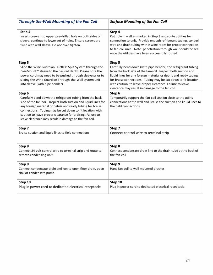
Through-the-Wall Mounting of the Fan Coil
Surface Mounting of the Fan Coil
Step 4 Insert screws into upper pre-drilled hole on both sides of sleeve, continue to lower set of holes. Ensure screws are
flush with wall sleeve. Do not over tighten.
Step 4 Cut hole in wall as marked in Step 3 and route utilities for connection to unit. Provide enough refrigerant tubing, control wire and drain tubing within wine room for proper connection to fan-coil unit. Note- penetration through wall should be seal once the utilities have been successfully routed.
Step 5 Slide the Wine Guardian Ductless Split System through the EasyMount™ sleeve to the desired depth. Please note the power cord may need to be pushed through sleeve prior to sliding the Wine Guardian Through-the-Wall system unit into sleeve (with pipe bender).
Step 5 Carefully bend down (with pipe bender) the refrigerant tubing from the back side of the fan-coil. Inspect both suction and liquid lines for any foreign material or debris and ready tubing for braise connections. Tubing may be cut down to fit location, with caution, to leave proper clearance. Failure to leave clearance may result in damage to the fan coil.
Step 6 Carefully bend down the refrigerant tubing from the back side of the fan-coil. Inspect both suction and liquid lines for any foreign material or debris and ready tubing for braise connections. Tubing may be cut down to fit location with caution to leave proper clearance for braising. Failure to leave clearance may result in damage to the fan coil.
Step 6 Temporarily support the fan-coil section close to the utility connections at the wall and Braise the suction and liquid lines to the field connections.
Step 7 Braise suction and liquid lines to field connections
Step 7 Connect control wire to terminal strip
Step 8 Connect 24-volt control wire to terminal strip and route to remote condensing unit
Step 8 Connect condensate drain line to the drain tube at the back of the fan-coil
Step 9 Connect condensate drain and run to open floor drain, open sink or condensate pump
Step 9 Hang fan-coil to wall mounted bracket
Step 10 Plug in power cord to dedicated electrical receptacle
Step 10 Plug in power cord to dedicated electrical receptacle.
25
Installing the Condensate Drain Connection
The Wine Guardian unit provides dehumidification for the inside of the wine cellar. It cools the
air down to the dew point corresponding to the temperature setpoint of the local user interface. If
the vapor barrier of the wine cellar is poorly constructed or excess moisture is in the basement,
the unit may remove excessive amounts of moisture from the wine cellar. The moisture appears in
the condensate drain of the unit.
NOTE: If moisture becomes excessive, install a room type dehumidifier to dehumidify the basement so as to not overload your Wine Guardian.
Installing the Drain Line
The factory supplied drain line must extend from the unit to an external drain or
disposal site. Do not use drain tubing any smaller than one-half inch inside
dimension on the unit.
If needed, splice a drain extension onto the drainline with a short piece of one-half
inch (1.27cm) – outside diameter – copper tubing and secure with clamps.
If no drain is available, use a bucket. Do not extend the drain below the rim of
the bucket. Empty the bucket periodically.
The Wine Guardian unit does not have an internal trap. A trap must be provided within the drain line for proper draining of the unit.
Allow enough height for the drain line to function properly. If draining into a nearby sink, the unit
must be elevated higher than the rim of the sink in order for the water to drain by gravity. Install
with a one-quarter inch per linear foot of pitch. Do not tie the condensate drain line directly into
the sanitary sewer system. See Accessories and Optional Equipment on page 6 for information
about the condensate pump.
Priming the Drain
The internal drain primes itself automatically once the unit has run for a period of time and after
the unit cycles off. This can be confirmed by water dripping from the drain.
26
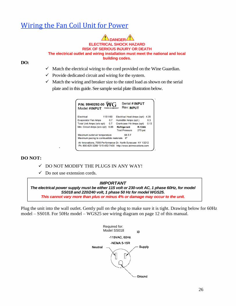
Wiring the Fan Coil Unit for Power
DANGER
ELECTRICAL SHOCK HAZARD
RISK OF SERIOUS INJURY OR DEATH
The electrical outlet and wiring installation must meet the national and local
building codes.
DO:
Match the electrical wiring to the cord provided on the Wine Guardian.
Provide dedicated circuit and wiring for the system.
Match the wiring and breaker size to the rated load as shown on the serial
plate and in this guide. See sample serial plate illustration below.
.
DO NOT:
DO NOT MODIFY THE PLUGS IN ANY WAY!
Do not use extension cords.
Plug the unit into the wall outlet. Gently pull on the plug to make sure it is tight. Drawing below for 60Hz
model – SS018. For 50Hz model – WGS25 see wiring diagram on page 12 of this manual.
IMPORTANT The electrical power supply must be either 115 volt or 230-volt AC, 1 phase 60Hz, for model
SS018 and 220/240 volt, 1 phase 50 Hz for model WGS25. This cannot vary more than plus or minus 4% or damage may occur to the unit.
Neutral
Required for: Model SS018
27
Installing the Condensing Unit
Condensing units are factory assembled with a sheet metal outdoor enclosure for
protection from the elements.
A minimum of 12 inches (30cm) is required around the perimeter of the condensing unit
for proper airflow across the coil, and to provide an adequate discharge airflow path
through the fan motor. Any obstructions to this airflow will result in a decrease in
performance, and possibly premature failure due to a buildup of high pressure within the
system.
The condensing unit is designed to operate in ambient temperatures ranging from 50°F-
115°F (minus 10°C -46°C) as it is supplied with many standard features to assist full
operation in this wide range. If required to operate in lower ambient conditions, it is
recommended that you order the low ambient option model condensing unit.
Mount the condensing unit above normal snowfall levels, so as to allow uninhibited winter
operation. A buildup of snow or any obstruction to airflow will result in a decrease in
performance and possible premature failure due to an increasingly high pressure within
the system.
Installation of Interconnecting Refrigerant Lines (Suction and Liquid)
NOTE: The interconnecting copper refrigerant lines shall be supplied by the installer. The larger suction line must be fully insulated along its complete length from condensing unit to fan coil unit. There is a factory-installed liquid line filter-drier inside the condensing unit; therefore, no additional drier is needed for proper operation. A liquid line moisture/sight glass is factory installed in the condensing unit to assist in monitoring the refrigerant charge, and the state of the refrigerant in the system.
Keep horizontal and vertical distances between the indoor and outdoor section as close as
possible to minimize refrigerant charge required. This will reduce system issues related to
oil management that can impair performance and jeopardize the compressor’s lubrication.
Provide a one-inch pitch in suction and liquid line toward the evaporator for every 10 feet
(3 meters) of run to prevent any refrigerant that condenses in the suction line from flowing
to the compressor when the unit is off. These two lines can be routed together and
wrapped together, as long as the suction line is fully insulated as previously directed.
Suction line riser traps are not required if the riser is properly sized to maintain refrigerant
velocity. Adding a trap will only increase pressure drop.
Prevent dips, sags, or other low spots that will trap refrigerant oil, which is an issue
especially with long horizontal runs. Use hard refrigerant copper for longer horizontal runs
to prevent potential oil return problems. (see sample piping chart on page 25)
When sweat connections are made in the connecting lines, be sure that the inside of the
tubing is clean before installing the unit. Use a dry nitrogen bleed during brazing. Note
that compressor suction and discharge valves should be open to atmosphere no longer than
15 minutes. Compressors with POE (polyolester) oil will quickly become contaminated
when opened to atmosphere.
28
NOTE: The suction line should be clamped near the inlet end of the vibration eliminator. The vibration eliminator is located between the clamp and the
compressor.
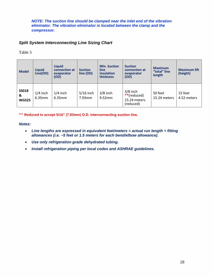
Split System Interconnecting Line Sizing Chart
Table 3
Model Liquid Line(OD)
Liquid connection at evaporator (OD)
Suction line (OD)
Min. Suction line insulation thickness
Suction connection at evaporator (OD)
Maximum “total” line length
Maximum lift (height)
SS018 & WGS25
1/4 inch 6.35mm
1/4 inch 6.35mm
5/16 inch 7.93mm
3/8 inch 9.52mm
3/8 inch **(reduced) 15.24 meters (reduced)
50 feet 15.24 meters
15 feet 4.52 meters
** Reduced to accept 5/16” (7.93mm) O.D. interconnecting suction line.
Notes:
Line lengths are expressed in equivalent feet/meters = actual run length + fitting allowances (i.e. ~5 feet or 1.5 meters for each bend/elbow allowance).
Use only refrigeration grade dehydrated tubing.
Install refrigeration piping per local codes and ASHRAE guidelines.
29
Sample Piping Configurations
Creates an oil trap
Evaporator
Condenser
Evaporator
Condenser
Condenser
Condenser
Evaporator Evaporator
Evaporator
Evaporator Evaporator
Condenser
Condenser
Condenser
Evaporator
Condenser
Soft copper sages and creates an oil trap
Incorrect Installation Correct Installation
Creates an oil trap
Oil runs away from condenser
30
Leak Checking and Evacuation Process
Pressurize and leak test the interconnecting lines, including the fan coil unit, fittings, and
brazed joints using the intended operating refrigerant, nitrogen, or dry air for leak testing.
A pressure equal to the low side test pressure marked on the unit nameplate is
recommended for leak testing. Repair any leaks found. Connect a good vacuum pump to
both the low and high side service valves while still in their factory supplied position,
isolating the refrigerant charge in the condensing unit. Draw a deep vacuum of at least
15pp microns. Do not use the motor compressor to pull a vacuum and do not operate the
motor compressor in a vacuum.
Evacuate the system to hold at 500 microns and break the vacuum by releasing the factory
refrigerant charge in the condensing unit to interconnect lines and fan coil unit by opening
service valves. Remove the vacuum pump. The system is now ready for optimal charging.
The condensing unit comes pre-refrigerant charged for 10 feet (3 meters) of
interconnecting tube. Charge the system with the correct amount of refrigerant and mark
the amount, with a ballpoint pen, in the space provided on the unit nameplate.
See Interconnecting Line Sizing Chart on page 24 for approximate additional
amount to add beyond 10 feet interconnecting tubing.
NOTE: When charging through the suction service valve the refrigerant should be charged in vapor form. NEVER CHARGE IN LIQUID FORM. Refrigerant should always be charged through a dryer. Charging in liquid form may damage the valve
plate assembly as well as scrub the oil out of the compressor bearings.
WARNING
NON-AZEOTROPES MUST BE CHARGED IN THE LIQUID PHASE ONLY. TO AVOID COMPRESSOR DAMAGE, LIQUID MUST ALWAYS BE CHARGED INTO THE HIGH SIDE OR INTO AN
ACCUMULATOR.
NOTE: Be sure there is not an overcharge of refrigerant. An overcharge might permit liquid refrigerant to enter the motor compressor and damage the valves, rods, pistons, etc.
Wiring
Wire the system as per the supplied wiring schematic found on pages 11 and 12 of this
manual.
The fan coil unit is powered through a factory-supplied power cord, but you will need
to run 24-volt power wires from the low voltage terminal block on the fan coil to the
factory supplied low voltage leads in the condensing unit. This can be typical
controller wire or 18 gauge insulated wire.
The condensing unit needs to be hard-wired for the rated high voltage to be brought to
the factory-installed contactor in condensing unit enclosure from the line side (L1 &
L2) of the contactor. Run a ground lead to be connected to the condensing unit Ground
lead/LUG. The load side of the factory-installed contactor will be factory-wired.
For low ambient models, turn on power to the condensing unit 24 hours prior to
system start-up to allow crankcase heater to warm up compressor crankcase.
31
Refrigerant Charging – for low ambient models only NOTE: The SS018 and WGS25 with low ambient option utilize a Headmaster control valve to control head pressure at low ambient applications, therefore require a specific initial charging procedure as outlined below.
Determining the amount of charge – When “refrigerant side” head pressure control is
utilized on a system, one of the most important factors is determining the total system
refrigerant charge. While on most packaged units the amount of charge is listed on the unit, the
required charge for a field built-up system cannot be listed by the manufacturer. Charge is
usually added when the system is started up until “proper” system performance is reached.
However, this is not satisfactory and if the system is to function properly year-round, the correct
amount of extra charge must be calculated ahead of time.
Procedures for Charging System with Low Ambient Option (Head
Pressure Control)
(SS018 and WGS25 Low Ambient Options only)
NOTE: When charging any system with head pressure control the outdoor ambient temperature must be known.
Charging of Systems with Head Pressure Control in temperatures above 70° F (21°C) --
After normal evacuation procedures:
1. Connect refrigerant cylinder to liquid line service valve port.
2. Charge liquid refrigerant into the high side of the system. Weighing the charge is
recommended.
3. Remove the refrigerant drum and connect it to the suction service valve.
4. Charge refrigerant vapor into the low side. Do not allow liquid refrigerant into the low
side.
5. Start the system.
6. Observe sight glass (factory-installed) to see if system is filling with refrigerant for normal
refrigeration cycle.
CAUTION
BUBBLES IN THE SIGHT GLASS CAN BE CAUSED BY FLASHING DUE TO PRESSURE DROP FROM PIPE OR ACCESSORY LOSSES, ETC.
7. If the Sight glass shows bubbles, more refrigerant may be required, while allowing
sufficient time for the refrigerant to stabilize and clear the Sight glass. Use supplied
information on the following pages for proper final charge.
32
Charging of Systems with head pressure Control in temperatures below 70° F (21°C) (After
normal evacuation procedures):
NOTE: When charging in ambient below 70°F (21°C) the procedure is very critical. Be sure to adhere to the following steps. Failure to do so will result in overcharging the system.
1. Follow instructions 1 through 7 above.
2. If the valve setting is correct for the system being charged, it is quite likely that some
refrigerant will be backed up into the condenser and the Sight glass will indicate bubbles
in the liquid line.
3. Add more refrigerant, while allowing sufficient time for the refrigerant to stabilize and
clear the Sight glass. Use supplied information on the following pages for proper final
charge.
4. At this point the system is correctly charged for this type of head pressure control at the
ambient temperature that exists while the charging procedure is taking place.
5. If the system is designed to operate at ambient below the ambient that exits during
charging, additional charge may have to be added now.
Good system performance during low ambient operation depends on proper refrigerant charge,
therefore, it is very important that this phase of the installation procedure be done carefully.
Poor system performance is often caused by over or under charging of refrigerant and may be the
most overlooked.
With the system started
After following instructions on the previous page Charging for Systems with Head Pressure
Control, with refrigerant tank now connected to suction line (low side) port to add remaining
charge in a gas state, refer to the provided charts for proper system operating points as equated
to ambient temperature with wine cellar at normal conditions of 57° F (13°C) / 55%RH. Refer
to Split Systems Operations chart on page 31 for system pressures, sub-cooling, and superheat
values to allow you to charge your system correctly.
In addition to using the Systems Operations Chart, there is a liquid line moisture/sight glass
located in the condensing (outdoor) unit as a useful guide to help determine if the system has
been sufficiently charged. HOWEVER, a full sight glass or a glass with bubbles does not
necessarily indicate the system is properly charged, or undercharged. There may be other
factors affecting sight glass, so do not charge by sight glass method only. A full sight glass-
matched with proper system pressures, sub-cooling, and superheat values is the proper method
for confirming that the system charge is correct for your application.
33
If you are not sure how to measure superheat or sub-cooling:
Superheat
Get an accurate suction line temperature on the suction line as close to the compressor inlet as
possible. At same time, attach a compound pressure gauge set to the system so as to read the
low side suction pressure at the suction service valve port (back seated valve stem to allow un-
restricted refrigerant flow from evaporator back to the compressor). Convert suction pressure
to a saturated temperature as derived from a pressure/temperature chart. Since the suction line
temperature is the higher value, subtract the saturated temperature from it to derive your
superheat. If your wine cellar is already at specified conditions e.g., 57° F (13°C), 55% RH),
and if your superheat is very low, or zero, you may have overcharged your system.
Sub-Cooling
With your compound pressure gauge set still installed with the high side connect to the valve
port on the liquid receiver (back seated valve stem to allow un-restricted refrigerant flow from
condenser to evaporator). Convert this liquid pressure to a saturated temperature from
pressure/temperature chart. Next, obtain your liquid line temperature by getting an accurate
reading on the liquid line BEFORE the TXV expansion on the indoor side. Obtain this
temperature entering the evaporator unit. Subtract the liquid line temperature from the
saturated liquid temperature to derive the system sub-cooling.
34
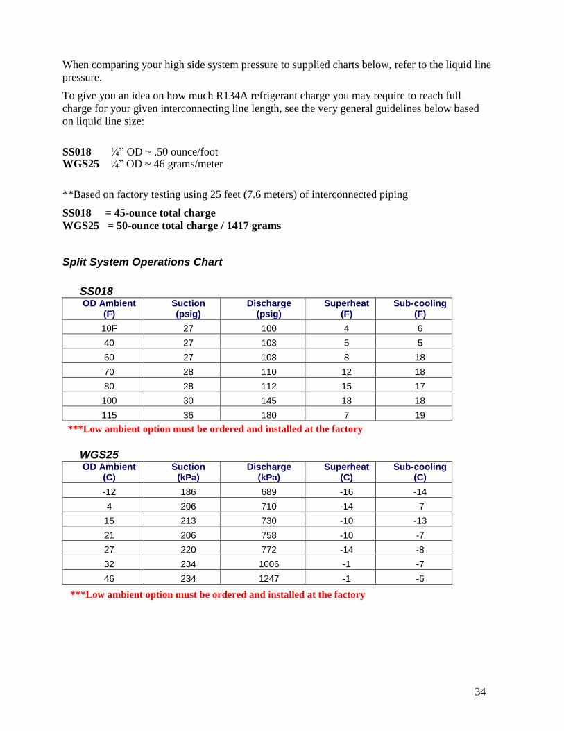
When comparing your high side system pressure to supplied charts below, refer to the liquid line
pressure.
To give you an idea on how much R134A refrigerant charge you may require to reach full
charge for your given interconnecting line length, see the very general guidelines below based
on liquid line size:
SS018 ¼” OD ~ .50 ounce/foot WGS25 ¼” OD ~ 46 grams/meter
**Based on factory testing using 25 feet (7.6 meters) of interconnected piping
SS018 = 45-ounce total charge
WGS25 = 50-ounce total charge / 1417 grams
Split System Operations Chart
SS018 OD Ambient
(F) Suction (psig)
Discharge (psig)
Superheat (F)
Sub-cooling (F)
10F 27 100 4 6
40 27 103 5 5
60 27 108 8 18
70 28 110 12 18
80 28 112 15 17
100 30 145 18 18
115 36 180 7 19
WGS25
OD Ambient (C)
Suction (kPa)
Discharge (kPa)
Superheat (C)
Sub-cooling (C)
-12 186 689 -16 -14
4 206 710 -14 -7
15 213 730 -10 -13
21 206 758 -10 -7
27 220 772 -14 -8
32 234 1006 -1 -7
46 234 1247 -1 -6
***Low ambient option must be ordered and installed at the factory
***Low ambient option must be ordered and installed at the factory
35
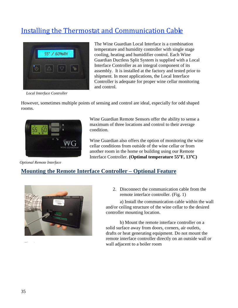
Installing the Thermostat and Communication Cable
The Wine Guardian Local Interface is a combination
temperature and humidity controller with single stage
cooling, heating and humidifier control. Each Wine
Guardian Ductless Split System is supplied with a Local
Interface Controller as an integral component of its
assembly. It is installed at the factory and tested prior to
shipment. In most applications, the Local Interface
Controller is adequate for proper wine cellar monitoring
and control.
However, sometimes multiple points of sensing and control are ideal, especially for odd shaped
rooms.
Wine Guardian Remote Sensors offer the ability to sense a
maximum of three locations and control to their average
condition.
Wine Guardian also offers the option of monitoring the wine
cellar conditions from outside of the wine cellar or from
another room in the home or building using our Remote
Interface Controller. (Optimal temperature 55°F, 13°C)
Mounting the Remote Interface Controller – Optional Feature
Local Interface Controller
Optional Remote Interface
2. Disconnect the communication cable from the
remote interface controller. (Fig. 1)
a) Install the communication cable within the wall
and/or ceiling structure of the wine cellar to the desired
controller mounting location.
b) Mount the remote interface controller on a
solid surface away from doors, corners, air outlets,
drafts or heat generating equipment. Do not mount the
remote interface controller directly on an outside wall or
wall adjacent to a boiler room
Fig. 1
36
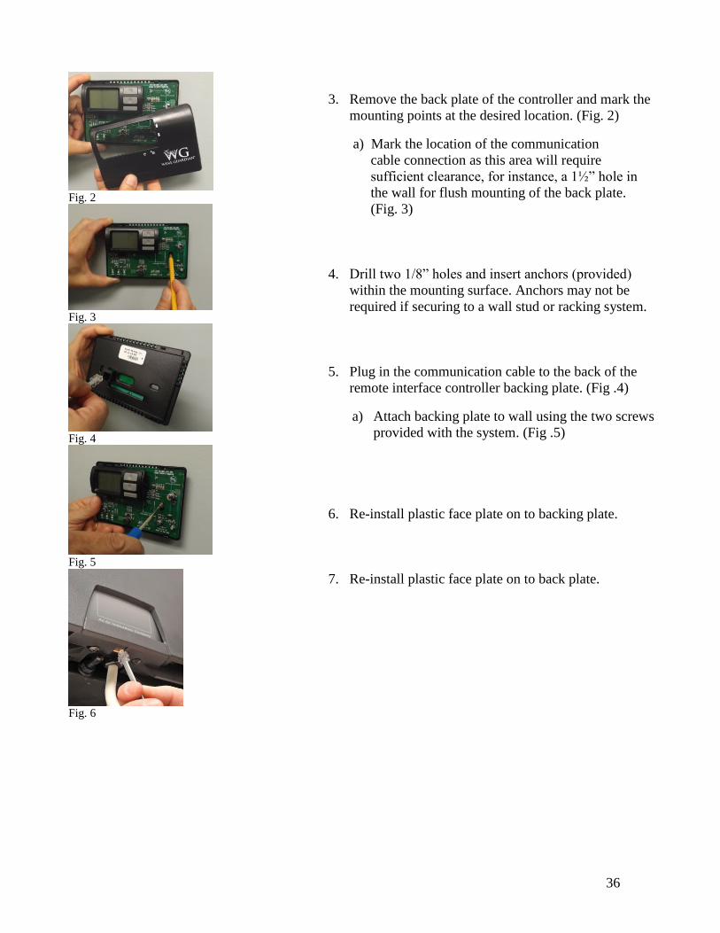
3. Remove the back plate of the controller and mark the
mounting points at the desired location. (Fig. 2)
a) Mark the location of the communication
cable connection as this area will require
sufficient clearance, for instance, a 1½” hole in
the wall for flush mounting of the back plate.
(Fig. 3)
4. Drill two 1/8” holes and insert anchors (provided)
within the mounting surface. Anchors may not be
required if securing to a wall stud or racking system.
5. Plug in the communication cable to the back of the
remote interface controller backing plate. (Fig .4)
a) Attach backing plate to wall using the two screws
provided with the system. (Fig .5)
6. Re-install plastic face plate on to backing plate.
7. Re-install plastic face plate on to back plate.
Fig. 2
Fig. 3
Fig. 4
Fig. 5
Fig. 6
37
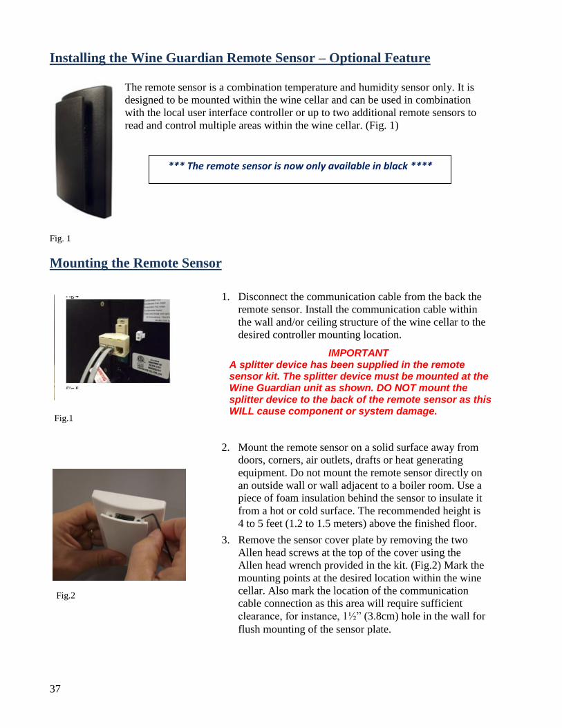
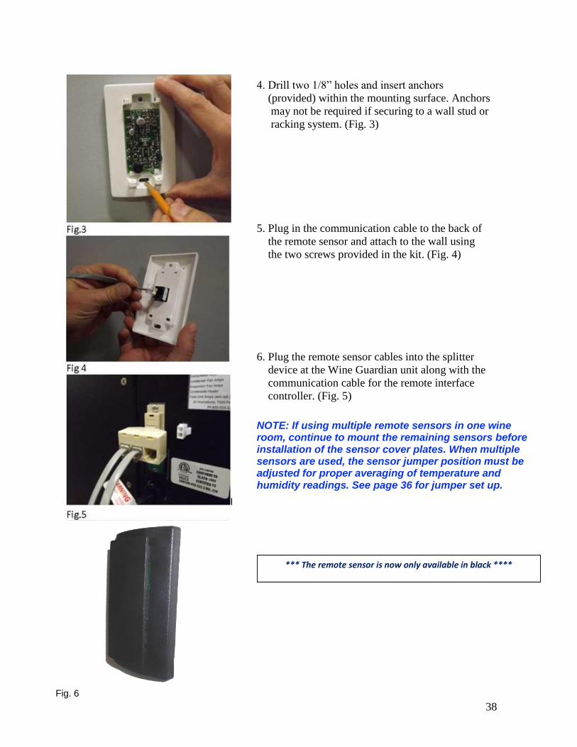
Installing the Wine Guardian Remote Sensor – Optional Feature
The remote sensor is a combination temperature and humidity sensor only. It is
designed to be mounted within the wine cellar and can be used in combination
with the local user interface controller or up to two additional remote sensors to
read and control multiple areas within the wine cellar. (Fig. 1)
Fig. 1
Mounting the Remote Sensor
Fig.1
1. Disconnect the communication cable from the back the
remote sensor. Install the communication cable within
the wall and/or ceiling structure of the wine cellar to the
desired controller mounting location.
2. Mount the remote sensor on a solid surface away from
doors, corners, air outlets, drafts or heat generating
equipment. Do not mount the remote sensor directly on
an outside wall or wall adjacent to a boiler room. Use a
piece of foam insulation behind the sensor to insulate it
from a hot or cold surface. The recommended height is
4 to 5 feet (1.2 to 1.5 meters) above the finished floor.
3. Remove the sensor cover plate by removing the two
Allen head screws at the top of the cover using the
Allen head wrench provided in the kit. (Fig.2) Mark the
mounting points at the desired location within the wine
cellar. Also mark the location of the communication
cable connection as this area will require sufficient
clearance, for instance, 1½” (3.8cm) hole in the wall for
flush mounting of the sensor plate.
Fig.2
IMPORTANT A splitter device has been supplied in the remote sensor kit. The splitter device must be mounted at the Wine Guardian unit as shown. DO NOT mount the splitter device to the back of the remote sensor as this WILL cause component or system damage.
*** The remote sensor is now only available in black ****
38
4. Drill two 1/8” holes and insert anchors
(provided) within the mounting surface. Anchors
may not be required if securing to a wall stud or
racking system. (Fig. 3)
5. Plug in the communication cable to the back of
the remote sensor and attach to the wall using
the two screws provided in the kit. (Fig. 4)
6. Plug the remote sensor cables into the splitter
device at the Wine Guardian unit along with the
communication cable for the remote interface
controller. (Fig. 5)
NOTE: If using multiple remote sensors in one wine room, continue to mount the remaining sensors before installation of the sensor cover plates. When multiple sensors are used, the sensor jumper position must be adjusted for proper averaging of temperature and humidity readings. See page 36 for jumper set up.
*** The remote sensor is now only available in black ****
Fig. 6
39
Joining the Communication Cable
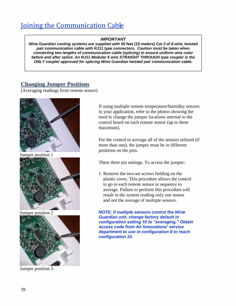
Changing Jumper Positions
(Averaging readings from remote sensor)
If using multiple remote temperature/humidity sensors
in your application, refer to the photos showing the
need to change the jumper locations internal to the
control board on each remote sensor (up to three
maximum).
For the control to average all of the sensors utilized (if
more than one), the jumper must be in different
positions on the pins.
There three pin settings. To access the jumper:
1. Remove the two-set screws holding on the
plastic cover. This procedure allows the control
to go to each remote sensor in sequence to
average. Failure to perform this procedure will
result in the system reading only one sensor
and not the average of multiple sensors.
NOTE: If multiple sensors control the Wine Guardian unit, change factory default in configuration setting 10 to “averaging.” Obtain access code from Air Innovations’ service department to use in configuration 8 to reach configuration 10.
Jumper position 1
Jumper position 2
Jumper position 3
IMPORTANT Wine Guardian cooling systems are supplied with 50 feet (15 meters) Cat 3 of 6-wire, twisted
pair communication cable with RJ11 type connectors. Caution must be taken when connecting two lengths of communication cable (splicing) to ensure uniform wire color
before and after splice. An RJ11 Modular 6 wire STRAIGHT THROUGH type coupler is the ONLY coupler approved for splicing Wine Guardian twisted pair communication cable.
40
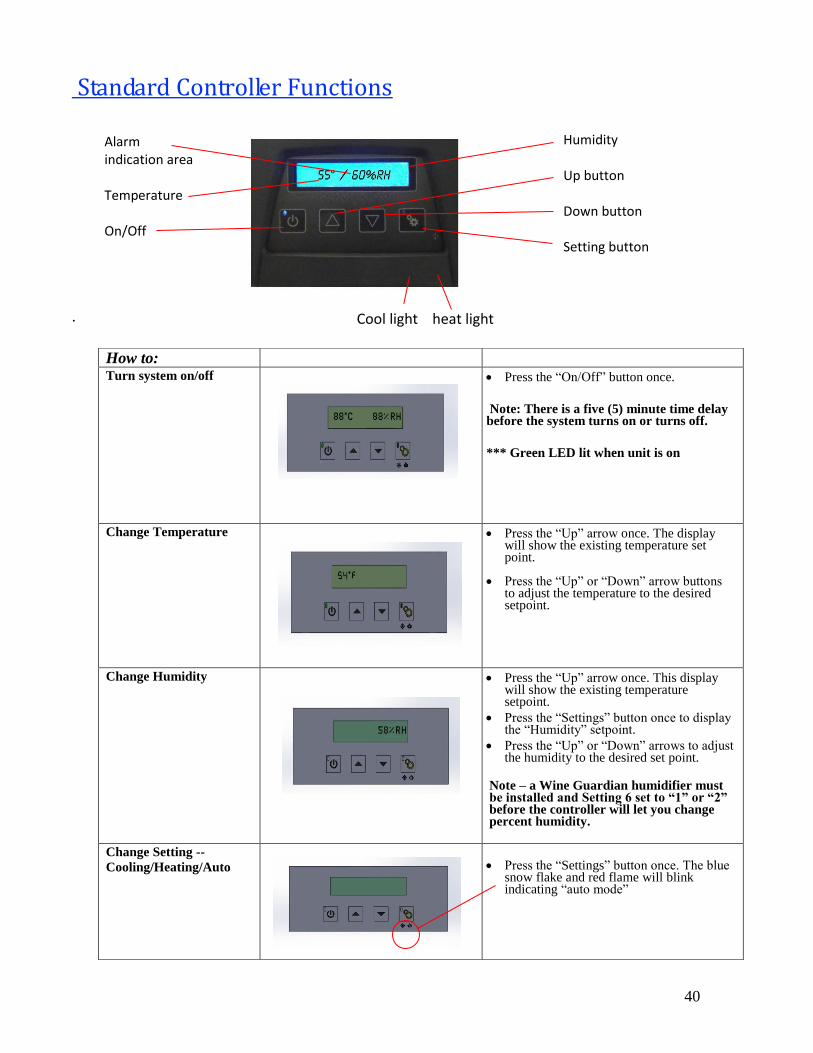
Standard Controller Functions
.
How to:
Turn system on/off
Press the “On/Off” button once.
Note: There is a five (5) minute time delay before the system turns on or turns off.
*** Green LED lit when unit is on
Change Temperature
Press the “Up” arrow once. The display will show the existing temperature set point.
Press the “Up” or “Down” arrow buttons to adjust the temperature to the desired setpoint.
Change Humidity
Press the “Up” arrow once. This display will show the existing temperature setpoint.
Press the “Settings” button once to display the “Humidity” setpoint.
Press the “Up” or “Down” arrows to adjust the humidity to the desired set point.
Note – a Wine Guardian humidifier must be installed and Setting 6 set to “1” or “2” before the controller will let you change percent humidity.
Change Setting --
Cooling/Heating/Auto
Press the “Settings” button once. The blue snow flake and red flame will blink indicating “auto mode”
Alarm indication area Temperature On/Off
Humidity Up button Down button Setting button
Cool light heat light
41
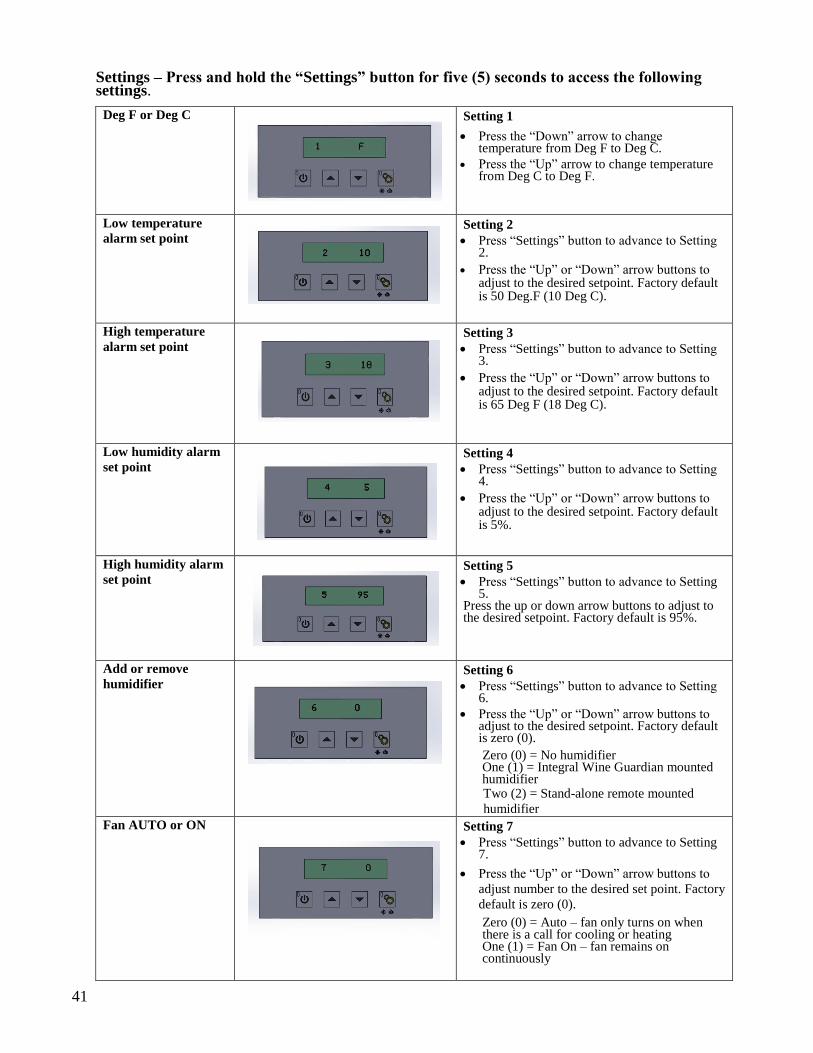
Settings – Press and hold the “Settings” button for five (5) seconds to access the following settings.
Deg F or Deg C
Setting 1
Press the “Down” arrow to change temperature from Deg F to Deg C.
Press the “Up” arrow to change temperature from Deg C to Deg F.
Low temperature
alarm set point
Setting 2
Press “Settings” button to advance to Setting 2.
Press the “Up” or “Down” arrow buttons to adjust to the desired setpoint. Factory default is 50 Deg.F (10 Deg C).
High temperature
alarm set point
Setting 3
Press “Settings” button to advance to Setting 3.
Press the “Up” or “Down” arrow buttons to adjust to the desired setpoint. Factory default is 65 Deg F (18 Deg C).
Low humidity alarm
set point
Setting 4
Press “Settings” button to advance to Setting 4.
Press the “Up” or “Down” arrow buttons to adjust to the desired setpoint. Factory default is 5%.
High humidity alarm
set point
Setting 5
Press “Settings” button to advance to Setting 5.
Press the up or down arrow buttons to adjust to the desired setpoint. Factory default is 95%.
Add or remove
humidifier
Setting 6
Press “Settings” button to advance to Setting 6.
Press the “Up” or “Down” arrow buttons to adjust to the desired setpoint. Factory default is zero (0).
Zero (0) = No humidifier One (1) = Integral Wine Guardian mounted humidifier
Two (2) = Stand-alone remote mounted
humidifier
Fan AUTO or ON
Setting 7
Press “Settings” button to advance to Setting 7.
Press the “Up” or “Down” arrow buttons to
adjust number to the desired set point. Factory
default is zero (0).
Zero (0) = Auto – fan only turns on when there is a call for cooling or heating One (1) = Fan On – fan remains on continuously
42
Advanced Settings--
Setting 8
Press “Settings” button to advance to Setting 8.
Press the up or down arrow buttons to
adjust number to the access code. Press
“Settings” button to continue onto setting
9 through 19.
Compressor anti-
short cycling time
Setting 9
Press “Settings” button to advance to Setting 9.
Press the “Up” or “Down” arrow buttons to adjust to the desired time in one-minute increments. Maximum is 10 minutes, minimum is 0 minutes.
Compressor anti-short cycling time is the amount of allowable time between compressor stop and restart. Rapid start/stop of compressors can cause premature failure. Factory default is 5 minutes.
WINE GUARDIAN DOES NOT RECOMMEND SETTINGS LOWER THAN FACTORY DEFAULT.
Set up remote sensor
or remote interface
controller
Setting 10
Press “Settings” button to advance to Setting 10.
Press the “Up” or “Down” arrow buttons to adjust to the desired setting.
rS = Remote sensor rI = Remote interface LI= Local interface – Through-the-wall unit only A = Averaging – Jumper position within sensors must be adjusted. See page 44.
Enable or disable
defrost sensor input
Setting 11
Press "Settings" button to advance to Setting 11.
Press the “Up” or “Down” arrow buttons to adjust to the desired setpoint
1 will equal enabled and a 0 (zero) will equal disabled.
43
Defrost cut in
temperature Setting 12
Press "Settings" button to advance to Setting 12.
Press the “Up” or “Down” arrow buttons to adjust to the desired setpoint
This setting will be adjustable from 25 Deg F to 40 Deg F (4 Deg C - 5 Deg C). Default will be 35 Deg F (2 Deg C).
There must be at least a 1 Deg F/C difference between defrost cut in and cut out set points.
Defrost cut out
temperature.
Setting 13
Press "Settings" button to advance to Setting 13.
Press the “Up” or “Down” arrow buttons to adjust to the desired setpoint.
This setting will be adjustable from 35 Def F to 50 Deg F (2 Deg C - 10 Deg C). Default will be 40 Deg F (5 Deg C).
There must be a least a 1 Deg F/C difference between defrost cut in and cut out set points.
Note: This setpoint must be 1 Deg F/C higher than setting 12.
Note: If C is selected and then switched back to F the default cut out will change to 41 Deg F.
Compressor run time
setting for defrost. Setting 14
Press "Settings" button to advance to Setting 14.
Press the “Up” or “Down” arrow buttons to adjust to the desired setpoint.
The setting for compressor run time can be adjustable from 1 to 12 hours in 1 hour increments. Default will be 1 hour.
Room sensor
calibration
Setting 15
Press “Settings” button to advance to Setting 15.
Press the “Up” or “Down” buttons to
adjust to the desired set point. Maximum
setting is +5, minimum setting is -5.
Factory default is zero (0). Sensor
calibration set point changes the actual
display reading (temperature only) by the
value of this setting.
Example: Sensor reading = 55 Deg F (13
Deg C)
Setting 15 set to +4
Display reading = 59 Deg F (15 Deg C)
44
RH% Sensor
Calibration
Setting 16
This setting will allow the adjustment of RH%
reading by +/-10%. Factory default is 13%RH.
Differential
temperature
adjustment
Setting 17
Press “Settings” button to advance to Setting 17
Press the “Up” or “Down” buttons to adjust to the desired setpoint.
This setting changes the system/compressor; turn
on temperature above setpoint. Factory default is
set to 1 Deg F.
Example: Sensor reading = 55 Deg F (13 Deg C)
Setting 17 Set to +3 Deg F (minus16 Deg C)
System/compressor turns on at 58 Deg F. (14 Deg
C)
Deadband setting
Setting 18
Press “Settings” button to advance to Setting 17.
Press the “Up” or “Down” buttons to adjust to the desired setpoint.
This setting is the minimal allowable temperature difference between heating and cooling setpoints. Maximum is 5 Deg F (minus 15 Deg C), minimum is 1 Deg F (minus 17 Deg C). Factory default is set to 2 Deg F (minus 16 Deg C)
Test mode setting
Setting 19
Press “Settings” button to advance to Setting 7.
Press the “Up” or “Down” buttons to adjust to the desired setpoint. When set to one the controller will automatically turn on all outputs with the exception of electric heat. Factory default is zero.
Zero (0) = Off.
One (1) = On
System Selection
Setting 20
DO NOT CHANGE
45
Alarm Codes
High temperature
alarm
Flashing temperature
number
Press the "Up" or "Down" arrow once to change
screen from alarm to normal temperature and
humidity indication. "Flashing temperature number"
along with flashing (!) symbol will remain on screen
until temperature falls below the High Temperature
Alarm set point (Setting 3).
Low temperature
alarm
Flashing temperature
number
Press the "Up" or Down" arrow once to change screen
from alarm to normal Temperature and humidity
indication. "Flashing temperature number" along with
flashing (!) symbol will remain on screen until
temperature rises above the Low Temperature Alarm
set point (Setting 2).
High humidity alarm
Flashing humidity
number
Press the “Up” or “Down” arrow once to change
screen from alarm to normal Temperature and
Humidity indication. "Flashing humidity number"
along with flashing (!) symbol will remain on screen
until humidity falls below the High Humidity Alarm
setpoint (Setting 5).
Low humidity alarm
Flashing humidity
number
Press the “Up” or “Down” arrow once to change
screen from alarm to normal Temperature and
Humidity indication. “Flashing humidity number”
along with flashing (!) symbol will remain on screen
until humidity rises above the Low Humidity Alarm
set point (Setting 4).
!1 = High Pressure
Switch Fault
THIS ALARM FORCES THE SYSTEM
TO SHUT DOWN
。
This alarm forces the system to shut down
Press the “Up” or “Down” arrow once to
change screen from alarm to normal
Temperature and Humidity indication.
“!1” will remain on screen until the High Pressure
reset switch has been reset. See the trouble shooting
guide page 55 for “Instructions to Reset High Pressure
Switch”
!2 = CS (Condensate
Switch Fault)
THIS ALARM FORCES THE SYSTEM
TO SHUT DOWN
This alarm forces the system to shut down
Press the “Up” or “Down” arrow once to
change screen from alarm to normal
Temperature and Humidity indication.
“!2” will remain on screen until the CS
(condensate switch) fault is resolved and reset
46
Inspection and Start Up Checklists
Receiving and Inspecting
Unit received undamaged
Unit received complete as ordered including accessories
Handling and Installing
Unit mounted on solid level surface
Sufficient space allowed for access to unit and accessories Proper electrical service
provided
Water provided to humidifier
Drain line installed properly
No obstructions to air flow around condensing unit
Starting-up the Unit
General visual inspection looks good. All wiring connections checked
Start unit
Confirm condenser airflow is unrestricted
Verify cooling and heating operation - optional
Check for excessive noise or vibration
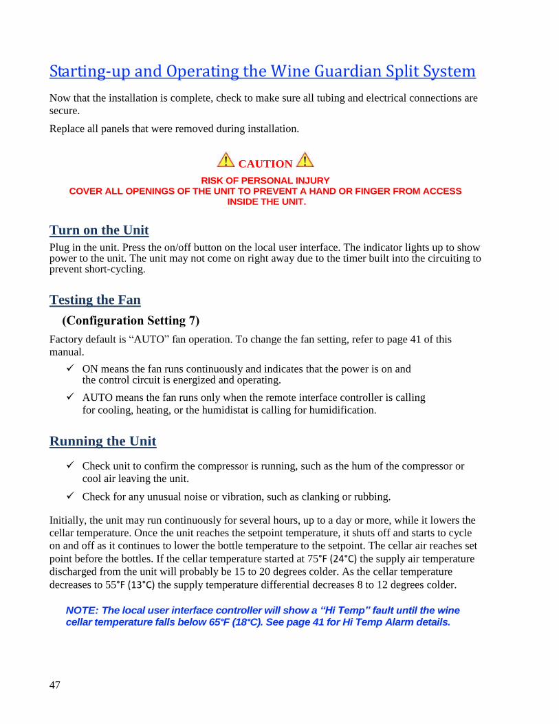
47
Starting-up and Operating the Wine Guardian Split System
Now that the installation is complete, check to make sure all tubing and electrical connections are
secure.
Replace all panels that were removed during installation.
CAUTION
RISK OF PERSONAL INJURY COVER ALL OPENINGS OF THE UNIT TO PREVENT A HAND OR FINGER FROM ACCESS
INSIDE THE UNIT.
Turn on the Unit
Plug in the unit. Press the on/off button on the local user interface. The indicator lights up to show power to the unit. The unit may not come on right away due to the timer built into the circuiting to prevent short-cycling.
Testing the Fan
(Configuration Setting 7)
Factory default is “AUTO” fan operation. To change the fan setting, refer to page 41 of this
manual.
ON means the fan runs continuously and indicates that the power is on and the control circuit is energized and operating.
AUTO means the fan runs only when the remote interface controller is calling
for cooling, heating, or the humidistat is calling for humidification.
Running the Unit
Check unit to confirm the compressor is running, such as the hum of the compressor or
cool air leaving the unit.
Check for any unusual noise or vibration, such as clanking or rubbing.
Initially, the unit may run continuously for several hours, up to a day or more, while it lowers the
cellar temperature. Once the unit reaches the setpoint temperature, it shuts off and starts to cycle
on and off as it continues to lower the bottle temperature to the setpoint. The cellar air reaches set
point before the bottles. If the cellar temperature started at 75°F (24°C) the supply air temperature
discharged from the unit will probably be 15 to 20 degrees colder. As the cellar temperature
decreases to 55°F (13°C) the supply temperature differential decreases 8 to 12 degrees colder.
NOTE: The local user interface controller will show a “Hi Temp” fault until the wine cellar temperature falls below 65°F (18°C). See page 41 for Hi Temp Alarm details.
48
Setting the Local User Interface Controller
Normal settings are between 54°F and 58°F (12°C and 14°C). If the optional heating coil is
furnished, enter a separate temperature setting to maintain the lower setting. To prevent the unit
from short cycling, the setting between heating and cooling cannot be closer than three degrees.
Regulating the Wine Cellar Temperature
Wine cellars have a natural temperature gradient of approximately 5 to 10 degrees between floor
and ceiling. To increase or decrease the temperature in various zones, remove the front plastic
cover and adjust the two air baffles to change the air flow patterns.
To keep the entire wine cellar at the same temperature, set the l interface controller to run the
supply fan continuously and not just when the cooling is operating. Set fan switch to ON instead
of AUTO.
NOTE: To monitor the cellar temperature, place thermometers in various locations in the cellar to monitor the temperature zones. Change the temperature in various zones by shifting the air flow patterns.
49
Maintenance
General
WARNING BEFORE PERFORMING MAINTENANCE ON THE UNIT, READ AND UNDERSTAND THE SAFETY
INFORMATION CONTAINED WITHIN THE SAFETY CHAPTER OF THE WINE GUARDIAN MANUAL.
DANGER HIGH VOLTAGE - RISK OF SERIOUS INJURY OR DEATH
HIGH VOLTAGES ARE PRESENT IN THE CABINETS. TURN OFF ALL POWER. USE THE LOCKOUT/TAGOUT PROCEDURE BEFORE OPENING PANELS.
CAUTION
SHARP EDGES
RISK OF SEROUS INJURY
SHARP EDGES ARE PRESENT ON THE FAN WHEELS, HOUSING, FINS AND COILS.
NOTE: Maintenance on Wine Guardian units requires working with high voltage and sheet metal with possible sharp edges. Only qualified personnel should perform maintenance. Some tasks require knowledge of mechanical and electrical methods. Make sure you are familiar with all hazards, general safety related procedures, and safety labels on the unit.
CAUTION
EXPOSURE TO MICROBIAL GROWTH (MOLD) CAN CAUSE SERIOUS HEALTH PROBLEMS
NOTE: Standing water in drain pans promote microbial growth (mold) that cause unpleasant odors and serious health-related indoor air quality problems. If mold is found, remove it immediately and sanitize that portion of the unit.
The Wine Guardian is designed for minimum maintenance. The refrigerant system is
hermetically sealed and requires no maintenance. The fans are permanently lubricated and
require no maintenance. Some maintenance to the unit may be required due to dust or dirt in the air
stream.
CAUTION SHARP EDGES RISK OF SERIOUS INJURY
SHARP EDGES ARE PRESENT ON THE FINS AND COILS.
50
Cleaning the Condensate Drain System
The condensate drain system traps dust and dirt. Clean the drain system once a year.
1. Press switch to Off and unplug the unit.
2. Make sure drain line allows free flow of water.
3. Inspect the drain pan under the coil.
4. If drain pan appears soiled, pour some hot water mixed with liquid bleach (diluted
solution) along the length of the pan to flush the dirt down the drain tube.
5. Continue this treatment until the drain appears clean and free of dirt.
6. Plug in the unit and restart.
Cleaning the Humidifier (optional)
If the unit was furnished with a humidifier it requires periodic maintenance. Follow the
instructions in the humidifier guide.
Heating Coil Option
The heating coil is located between the evaporator coil and blower. It contains the heating element
and high temperature limit switches. The heating coil is wired to work in conjunction with the
local user interface controller. Since the local user interface controller prevents the heating and
cooling circuits from being energized at the same time, no additional power wiring is needed. We
do recommend using the AUTO mode on the local user interface controller so it can switch from
heating to cooling automatically. If using either the heat or cool only mode, the local user
controller will not switch automatically.
No additional maintenance is required for the heating coil. To test the heating coil operation, set
the local user interface controller on HEAT and set the temperature above the cellar temperature.
The supply air temperature should rise above the return air temperature by an amount shown in
the specifications.
51
Maintenance Schedule
Monthly
(or quarterly depending on experience with individual cellar) Check and drain trap – clean if
needed.
Check for noise or vibration.
Check for short-cycling of the unit – turning on and off the compressor unit more than eight times/hour.
Yearly
(in addition to monthly)
Check evaporator and condensing unit for dirt – use a vacuum with a brush attachment to clean the coils.
Clean condensate pan under the evaporator coil by flushing. Be careful to keep the drain pans clear of any and all debris.
Inspect cabinet for corrosion or rusting – clean and paint.
Inspect for dirt buildup on or inside the unit. Clean unit by vacuuming or wiping it down.
Check for loose insulation, fasteners, gaskets or connections.
Check the wiring connections and integrity or cords.
Examine ducts for any cracks or breach.
Check fan and solenoid on humidifier.
Replace humidifier pad (if used).
52
Troubleshooting
WARNING
BEFORE PROCEEDING, READ AND UNDERSTAND THE SAFETY INFORMATION CONTAINED IN
THE SAFETY SECTION OF THE WINE GUARDIAN MANUAL.
Typical start up problems
Possible Cause
Loose, improper or defective remote interface
controller or humidistat cable
Solution
Check power, and remote interface
controller or humidistat cable
Incorrect remote interface controller or
humidistat (optional) settings
Check the remote interface controller and optional humidistat setup for the application
Changed settings on the remote interface
controller
A common problem is not waiting long
enough for the internal timers to complete
their timed delay
Unit does not start up
Power Switch Light is Off
Possible Cause Solution
Switch not on Turn on switch
No power to outlet Check circuit breaker and wiring
Unit not plugged in Plug in the unit
Power switch light is on and the remote interface controller light is off
Possible Cause Solution
No power to remote interface controller Check main control board for L.E.D. indication
Check wiring for loose, broken or frayed connections
Check wiring for proper splicing
Remote interface controller may be faulty
Remote Interface Controller may be faulty
Power switch light is on and the remote interface controller light is on
Possible Cause Solution
Remote interface controller is not set up Check remote interface controller set up in the properly guide
Press fan ON switch to check evaporator fan only
IMPORTANT
This section is intended as a diagnostic aid only. For detailed repair or parts replacement procedures, contact a qualified service company. Check the following table for some
solutions before calling a service technician.
53
Unit is operating and blows evaporator air, but the supply air is not colder than the return air from the cellar
Possible Cause Solution
Remote interface controller not set up Check remote interface controller setup in the
properly manufactures guide
Compressor not operating High pressure switch open (button up)
Alarm will appear on local user interface
controller
Condenser airflow is blocked Remove blockage
Clean filter and coil (if needed)
Head Pressure (HP) switch is open
Reset HP switch See reset instructions on pg. 55
Cellar temperature too cold (below 51 degrees) when unit is running Possible Cause Solution
Local user interface controller set too low on
cooling
Heating coil (optional) not operating
Local user interface controller set too low on
heating
Local user interface controller not
controlling temperature
Reset local user interface controller to higher
cooling temperature
Check for remote interface controller rise across
coil
Reset local user interface controller to higher
heating temperature
Local user interface controller mounted in
improper location
Cellar temperature too cold (below 51 degrees) when unit is not running
Possible Cause Solution Too much heat loss to adjacent spaces
Cellar loads are too high
Increase insulation around the ductwork
Check and clean filter and coil
Coil frozen – shut off unit for two hours
Install additional insulation
Humidity too low or supply air is too cold, without optional humidifier Possible Cause Solution Not enough evaporator airflow
Defective thermal expansion valve
Temperature set too cold
Remove blockage in supply or return ductwork
Check and clean filter and coil
Coil frozen – shut off unit for two hours
If under warranty call for service
If not under warranty call a refrigeration
technician
Raise temperature setpoint
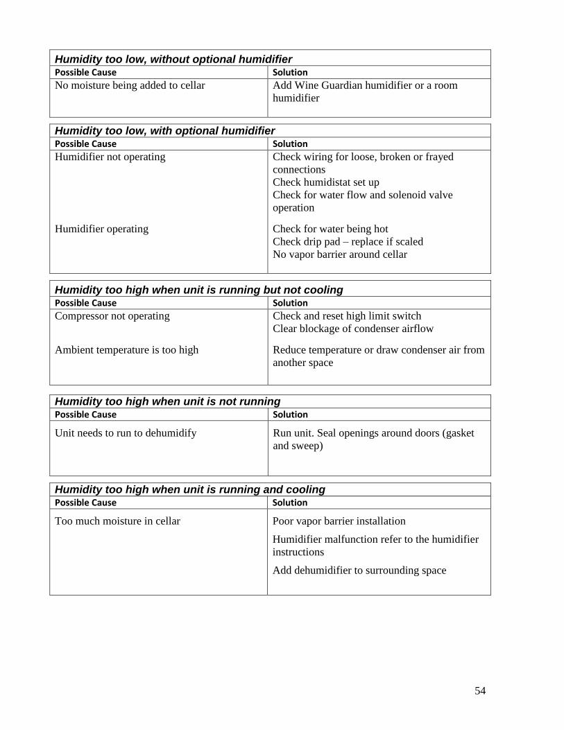
54
Humidity too low, without optional humidifier Possible Cause Solution No moisture being added to cellar
Add Wine Guardian humidifier or a room
humidifier
Humidity too low, with optional humidifier Possible Cause Solution Humidifier not operating
Humidifier operating
Check wiring for loose, broken or frayed
connections
Check humidistat set up
Check for water flow and solenoid valve
operation
Check for water being hot
Check drip pad – replace if scaled
No vapor barrier around cellar
Humidity too high when unit is running but not cooling Possible Cause Solution Compressor not operating
Ambient temperature is too high
Check and reset high limit switch
Clear blockage of condenser airflow
Reduce temperature or draw condenser air from
another space
Humidity too high when unit is not running Possible Cause Solution
Unit needs to run to dehumidify
Run unit. Seal openings around doors (gasket
and sweep)
Humidity too high when unit is running and cooling Possible Cause Solution
Too much moisture in cellar
Poor vapor barrier installation
Humidifier malfunction refer to the humidifier
instructions
Add dehumidifier to surrounding space
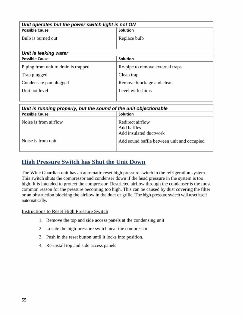
55
Unit operates but the power switch light is not ON Possible Cause Solution
Bulb is burned out
Replace bulb
Unit is leaking water Possible Cause Solution
Piping from unit to drain is trapped
Trap plugged
Condensate pan plugged
Unit not level
Re-pipe to remove external traps
Clean trap
Remove blockage and clean
Level with shims
Unit is running properly, but the sound of the unit objectionable Possible Cause Solution
Noise is from airflow
Noise is from unit
Redirect airflow
Add baffles
Add insulated ductwork
Add sound baffle between unit and occupied
High Pressure Switch has Shut the Unit Down
The Wine Guardian unit has an automatic reset high pressure switch in the refrigeration system.
This switch shuts the compressor and condenser down if the head pressure in the system is too
high. It is intended to protect the compressor. Restricted airflow through the condenser is the most
common reason for the pressure becoming too high. This can be caused by dust covering the filter
or an obstruction blocking the airflow in the duct or grille. The high-pressure switch will reset itself
automatically.
Instructions to Reset High Pressure Switch
1. Remove the top and side access panels at the condensing unit
2. Locate the high-pressure switch near the compressor
3. Push in the reset button until it locks into position.
4. Re-install top and side access panels
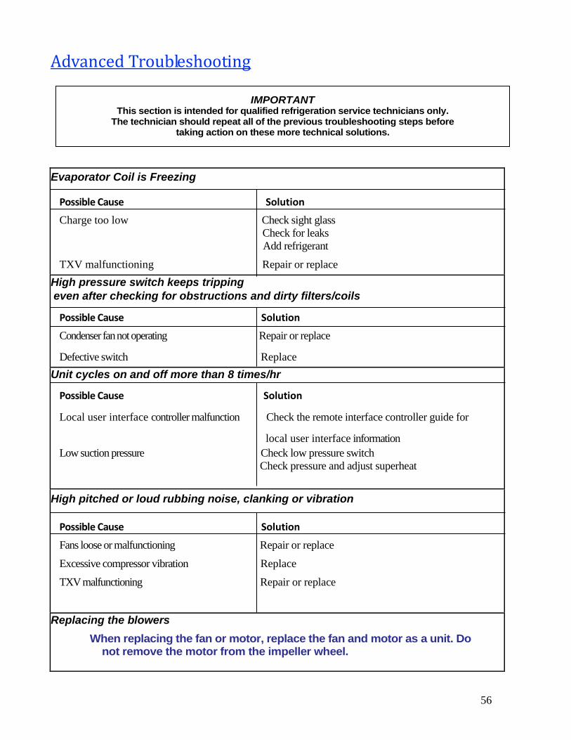
56
Advanced Troubleshooting
Evaporator Coil is Freezing
Possible Cause Solution
Charge too low Check sight glass
Check for leaks
Add refrigerant
TXV malfunctioning Repair or replace
High pressure switch keeps tripping
even after checking for obstructions and dirty filters/coils
Possible Cause Solution
Condenser fan not operating Repair or replace
Defective switch Replace
Unit cycles on and off more than 8 times/hr
Possible Cause Solution
Local user interface controller malfunction Check the remote interface controller guide for
local user interface information
Low suction pressure Check low pressure switch
Check pressure and adjust superheat
High pitched or loud rubbing noise, clanking or vibration
Possible Cause Solution
Fans loose or malfunctioning Repair or replace
Excessive compressor vibration Replace
TXV malfunctioning Repair or replace
Replacing the blowers
When replacing the fan or motor, replace the fan and motor as a unit. Do not remove the motor from the impeller wheel.
IMPORTANT This section is intended for qualified refrigeration service technicians only.
The technician should repeat all of the previous troubleshooting steps before taking action on these more technical solutions.
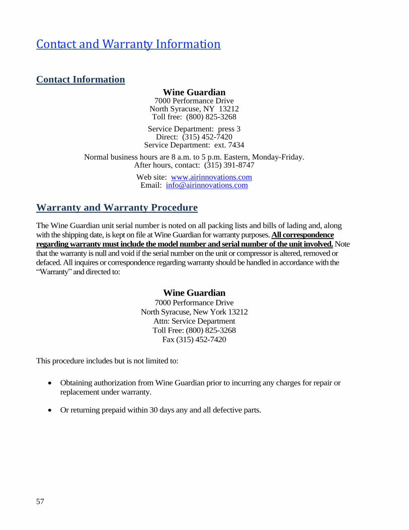
57
Contact and Warranty Information
Contact Information
Wine Guardian 7000 Performance Drive
North Syracuse, NY 13212 Toll free: (800) 825-3268
Service Department: press 3 Direct: (315) 452-7420
Service Department: ext. 7434
Normal business hours are 8 a.m. to 5 p.m. Eastern, Monday-Friday. After hours, contact: (315) 391-8747
Web site: www.airinnovations.com Email: [email protected]
Warranty and Warranty Procedure
The Wine Guardian unit serial number is noted on all packing lists and bills of lading and, along
with the shipping date, is kept on file at Wine Guardian for warranty purposes. All correspondence
regarding warranty must include the model number and serial number of the unit involved. Note
that the warranty is null and void if the serial number on the unit or compressor is altered, removed or
defaced. All inquires or correspondence regarding warranty should be handled in accordance with the
“Warranty” and directed to:
Wine Guardian
7000 Performance Drive
North Syracuse, New York 13212
Attn: Service Department
Toll Free: (800) 825-3268
Fax (315) 452-7420
This procedure includes but is not limited to:
Obtaining authorization from Wine Guardian prior to incurring any charges for repair or
replacement under warranty.
Or returning prepaid within 30 days any and all defective parts.
58
Manufacturer’s Warranty – U.S. and Canada Only
Warranty outside of the U.S. is determined by the country. Refer to your distributor for your Wine Guardian warranty.
GENERAL
Wine Guardian warrants, to the original buyer, its goods and all parts thereof to be free from defects in material and workmanship for a period of two (2) years from the date of invoicing assuming NORMAL USE AND SERVICE.
LIABILITY
Wine Guardian liability shall be limited to the repair or replacement (at its option) of any part, which, at our sole discretion, is determined to be defective. The purchaser shall pay all transportation costs. Additionally, if a malfunction occurs within the first year from the date of invoice, Wine Guardian will reimburse the reasonable cost of labor required for the repair or replacement provided authorization is obtained from one of our authorized representatives prior to incurring any labor charges.
LIMITATIONS OF LIABILITY
THESE WARRANTIES ARE MADE IN LIEU OFF ALL OTHER WARRANTIES EXPRESSED OR IMPLIED, INCLUDING ANY IMPLIED WARRANTY OF MERCHANTABILITY OR FITNESS FOR A PARTICULAR PURPOSE AND IN LIEU OF ANY OTHER OBLIGATION OR LIABILITY, INCLUDING LIABILITY FOR ANY INCIDENTAL OR CONSQUENTIAL DAMAGES. Wine Guardian will not be responsible for any costs or liabilities whatsoever resulting from improper installation or service of its equipment. In the event that Wine Guardian or its distributors are found liable for damage based on any defect or nonconformity in the products, their total liability for each defective product shall not exceed the purchase price of such defective products. No person or representative is authorized to change these warranties or assume any other obligations or liabilities for Wine Guardian in connection with the sale of its systems.
INDEMNIFICATION
Purchaser agrees to indemnify, hold harmless and defend seller and its officers, directors, agents and employees from and against any and all claims, liabilities, costs and expenses arising out of or related to Purchaser’s use of the goods, or in any way involving injury to person or property or accident occasioned by the goods sold by Wine Guardian to Purchaser.
FOREIGN GOVERNMENT AND INDIAN NATIONS
If Purchaser is a foreign government or an Indian nation, Purchaser hereby expressly waives its defense of sovereign immunity in the event of a dispute between Purchaser and Wine Guardian regarding this invoice and Purchaser expressly acquiesces to the jurisdiction of the federal and state courts of the United States.
SEVERABILITY
If one or more of the provisions contained in this contract shall for any reason be held to be invalid, illegal or unenforceable in any respect, such invalidity, illegality or unenforceability shall not affect any provision of this contract, but this contract shall be construed as if such invalid, illegal or unenforceable provision had never been contained.
ADDITONAL REQUIREMENTS
If a defect covered by the Warranty occurs, contact Wine Guardian for authorization to proceed with corrective action. Do not return any parts or incur any charges for which you expect to be reimbursed under this Warranty without receiving this authorization. If parts are replaced under this Warranty, the defective parts must be returned prepaid within 30 days. This warranty shall be null and void in its entirety if the Serial Number on the air conditioner or compressor is altered, removed or defaced.