Embed Size (px)
Citation preview
High Precision,Digital Pressure Switch
Series ZSE40/ISE40
16-2-15
ZSEISE
PSEZI SE3
PSZI SE1
2
ZSP
ISA2
IS
ZSM
PF2
IF
Data

Anti-chattering functionDevices such as large bore cylinders and high-flow vacuum ejectors consume a large volume of air when they operate, and this may cause a momentary drop in the primary pressure. This function prevents such momentary pressure drops from being detected as abnormal pressures by allowing the response time selection to be changed.
[Selectable response times: t] 2.5 ms (normal), 24 ms, 192 ms or 768 msThe normal setting is selected when shipped from the factory.
(Operating principle) The pressure values measured within the user-selected response time are averaged, and switch output (ON/OFF) is determined by comparing this averaged pressure value with the set pressure.
PressureMomentary change
t (ms) t (ms)Time →
Time →
Time →
(Averaging) (Averaging)
Set value
Switch outputoperation
when normal
ON
OFF
Switch outputoperation whenanti-chattering
function is used
ON
OFF
P1P2
Repeatability±0.2% F.S. ±1 digit or less
IP65 compatibleDusttight/Splash proof type
Auto shift function
Erroneous operation may occur if there is fluctuation in the primary pressure.The auto shift function compensates for pressure changes to ensure proper ON/OFF switch response during such fluctuations.
(Operating principle) At the point when the primary pressure fluctuates, the set pressure value is compensated by setting the auto shift input (external input) to low (no-voltage) input, using the pressure measured at that point as a standard.
Without using auto shiftWhen the primary pressure fluctuates, a correct determination becomes impossible.
When using auto shift
Time →
Time →
Time →
Time →
Time →
ON
OFF
Switch output1, 2
Hi
Lo
Auto shiftinput
5 ms or more10 msor less
Switch output response timewhen auto shift is input.
Set valueP1
P2
Set valueP1
P2
Switch output1, 2
ON
OFF
PressurePrimary pressure normal Primary pressure drop
Does not turn ONDoes not turn OFF
Primary pressure increase
Primary pressure normal
Set value compensation Set value compensation
Primary pressure drop Primary pressure increasePressure
[ ]
→→
→
High speed response: 2.5 ms or lessWith anti-chattering functionStable switch output is possible even with sudden
With auto shift functionAllows switch output unaffected by variations in primary pressure.
3 types of pipingDifferent piping methods are possible to accommodate the installation location.
Compound pressure (ZSE40F) Able to detect suction pressure (vacuum pressure) and release pressure (positive pressure) with a single pressure switch.
16-2-16
16-2-17
ZSEISE
PSEZI SE3
PSZI SE1
2
ZSP
ISA2
IS
ZSM
PF2
IF
Data
Series ZSE40/ISE40High Precision,
Digital Pressure Switch
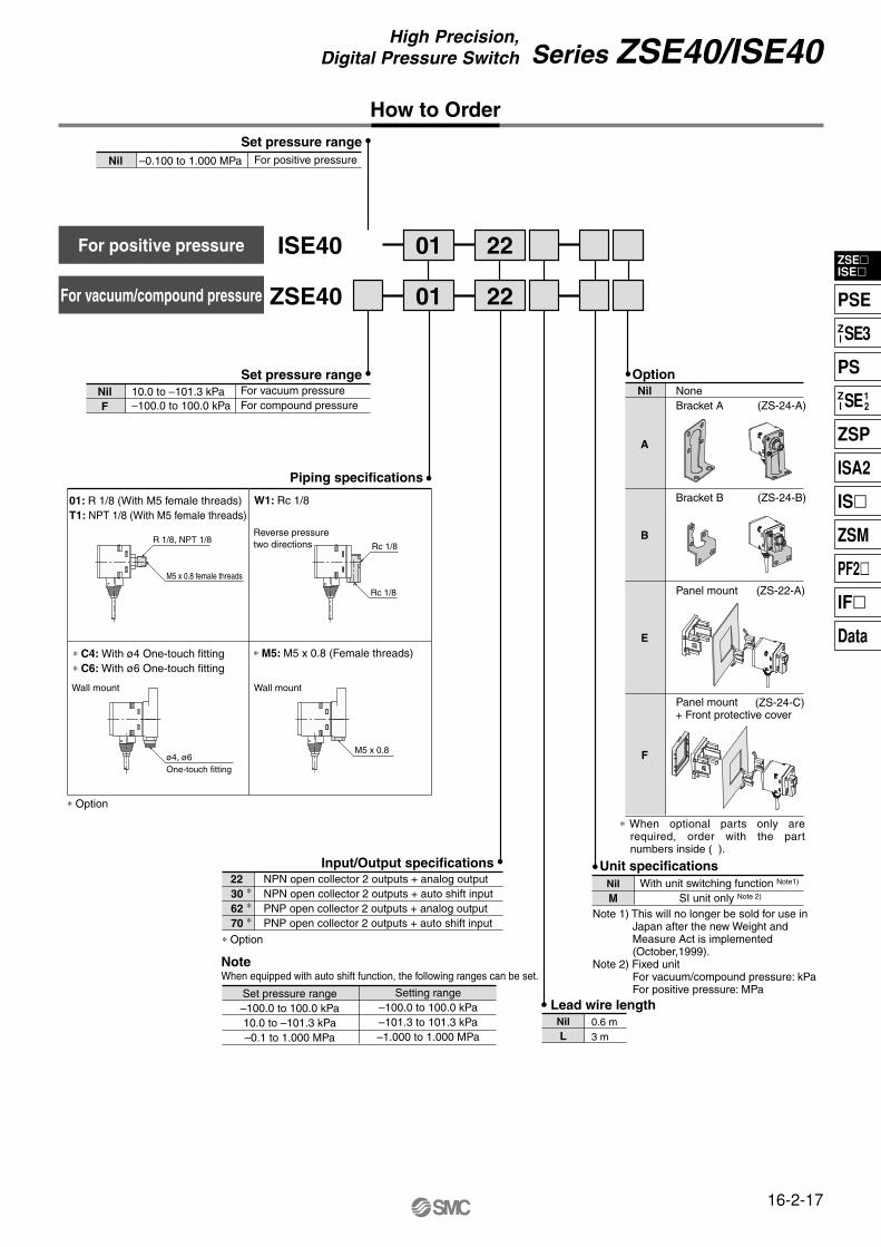
How to Order
ZSE40 01
ISE40 01
22
22
For vacuum/compound pressure
For positive pressure
10.0 to –101.3 kPa–100.0 to 100.0 kPa
Set pressure rangeNilF
–0.100 to 1.000 MPa For positive pressure
Set pressure rangeNil
Unit specificationsNilM
With unit switching function Note1)
SI unit only Note 2)
NilL
Lead wire length0.6 m3 m
∗ Option
NPN open collector 2 outputs + analog outputNPN open collector 2 outputs + auto shift inputPNP open collector 2 outputs + analog outputPNP open collector 2 outputs + auto shift input
Input/Output specifications22
30 ∗ 62 ∗ 70 ∗
Setting range–100.0 to 100.0 kPa–101.3 to 101.3 kPa–1.000 to 1.000 MPa
Set pressure range–100.0 to 100.0 kPa10.0 to –101.3 kPa–0.1 to 1.000 MPa
OptionNil
A
NoneBracket A (ZS-24-A)
B
Bracket B (ZS-24-B)
E
Panel mount (ZS-22-A)
F
Panel mount+ Front protective cover
Piping specifications
01: R 1/8 (With M5 female threads)T1: NPT 1/8 (With M5 female threads)
R 1/8, NPT 1/8
M5 x 0.8 female threads
∗ M5: M5 x 0.8 (Female threads)
M5 x 0.8
∗ C4: With ø4 One-touch fitting∗ C6: With ø6 One-touch fitting
Wall mount Wall mount
∗ Option
ø4, ø6One-touch fitting
W1: Rc 1/8
Rc 1/8
Reverse pressuretwo directions
Rc 1/8
For vacuum pressureFor compound pressure
NoteWhen equipped with auto shift function, the following ranges can be set.
Note 1) This will no longer be sold for use in Japan after the new Weight and Measure Act is implemented (October,1999).
Note 2) Fixed unitFor vacuum/compound pressure: kPaFor positive pressure: MPa
(ZS-24-C)
∗ When optional parts only are required, order with the part numbers inside ( ).

16-2-18
Series ZSE40/ISE40
Specifications
Example of Internal Circuit and Wiring
Rated pressure rangeOperating pressure range/Set pressure rangeWithstand pressure
Set pressure resolution Note 1)
Applicable fluid
Power supply voltageCurrent consumption
Switch output
Repeatability
Hysteresis
Response time (With anti-chattering function)
Output short circuit protectionDisplay
Display accuracy
Indicator light
Analog output Note 2)
Auto shift input Note 3)
Environmental resistance
Temperature characteristics
Port size
Lead wireWeight
ZSE40F (Compound pressure)
–100.0 to 100.0 kPa–100.0 to 100.0 kPa
500 kPa0.1—
0.0010.001
0.02 0.011
0.1Air, Non-corrosive/Non-flammable gas
12 to 24 VDC ±10%, Ripple (p-p) 10% or less55 mA or less
NPN or PNP 2 outputs Max. load current : 80 mAMax. applied voltage: 30 VDC (With NPN output) Residual voltage : 1 V or less (With 80 mA load current)
±0.2% F.S. ±1digit or lessVariable
Fixed (3 digits) Note4)
2.5 ms or less (With anti-chattering function: 24 ms, 192 ms and 768 ms selections) Yes
3 1/2 digit LED display (Sampling cycle: 5 times/sec.)
±2% F.S. ±1 digit or less (at ambient temperature of 25 ±3°C)
Green LED (OUT1: Lights when ON), Red LED (OUT2: Lights when ON)
Output voltage: 1 to 5 V±5% F.S. or less (in rated pressure range)
Linearity: ±1% F.S. or lessOutput impedance: Approx. 1 kΩ
No-voltage input (Reed or solid state), input 5 ms or moreIP65
Operating: 0 to 50˚C, Stored: –10 to 60˚C (No condensation or freezing) Operating/Stored: 35 to 85% RH (No condensation) 1000 VAC for 1 min. between lead wires and body
50 MΩ or more (at 500 VDC) between lead wires and body10 to 500 Hz at the smaller of amplitude 1.5 mm or acceleration 98 m/s2 (10 G) in X, Y, Z directions for 2 hrs. each (De-energized)
980 m/s2 (100 G) in X, Y, Z directions 3 times each (De-energized) In a temperature range of 0 to 50°C, ±2% F.S. or less of pressure measured at 25°C
01: R 1/8, M5 x 0.8, T1: NPT1/8, M5 x 0.8, W1: Rc 1/8C4: With ø4 One-touch fitting, C6: With ø6 One-touch fitting, M5: M5 female threads
5-wire oil resistant heavy-duty cord (0.15 mm2)01/T1 types approx. 60 g, W1 type approx. 80 g, C4/C6/M5 types approx. 92 g (Each including 0.6 m lead wires)
ZSE40 (Vacuum pressure)
0.0 to –101.3 kPa10.0 to –101.3 kPa
Output voltage: 1 to 5 V ±2.5% F.S. or less (in rated pressure range) Linearity: ±1% F.S. or less
Output impedance: Approx. 1 kΩ
ISE40 (Positive pressure) 0.000 to 1.000 MPa–0.100 to 1.000 MPa
1.5 MPa—
0.0010.010.010.1——
kPaMPa
kgf/cm2
barpsi
mmHg
InHg
Hysteresis mode
EnclosureAmbient temperature rangeAmbient humidity rangeWithstand voltage
Insulation resistance
Vibration resistanceImpact resistance
Window comparator mode
Setting range–100.0 to 100.0 kPa–101.3 to 101.3 kPa
–1.000 to 1.000 MPa
Set pressure range–100.0 to 100.0 kPa10.0 to –101.3 kPa– 0.1 to 1.000 MPa
Note)When equipped with auto shift function, the following ranges can be set.
Note 1) Equipped with unit switching function(Types without the unit switching function use SI units (kPa or MPa) only.)
Note 2) For ZSE40 (F)/ISE40--2262
Note 3) For ZSE40 (F)/ISE40--3070
Note 4) For ZSE40F (compound pressure) with “psi” indication, this is 0.03 to 0.04 psi.
Note 5) For ZSE40F (compound pressure) with “psi” indication, zero clear is in the range of ±0.01 psi.
Mai
n ci
rcui
t
Load
Load1 kΩ
12 to 24 VDC
DC (+) (Brown)
Analog output(Gray) OUT1(Black) OUT2(White)
DC (–) (Blue)
Mai
n ci
rcui
t
1.2 kΩ
6.8 kΩ Load
Load
12 to 24 VDC
DC (+) (Brown) Auto shift input(Gray) OUT1(Black) OUT2(White)
DC (–)
(Blue)
ZSE40(F) ISE40--22(L)-(M) With analog output
ZSE40(F) ISE40--62(L)-(M) With analog output
ZSE40(F)ISE40--30(L)-(M)With auto shift input
ZSE40(F) ISE40--70(L)-(M) With auto shift input
Mai
n ci
rcui
t
1 kΩ
12 to 24 VDC
DC (+) (Brown) Analog output(Gray)
OUT1(Black)OUT2(White)
DC (–)(Blue)
Mai
n ci
rcui
t
1.2 kΩ
6.8 kΩ
Load
12 to 24 VDC
DC (+) (Brown) Auto shift input(Gray)
OUT1(Black) OUT2(White)
DC (–) (Blue)
Load
Load
Load

kPa
OUT2OUT1
SET
Description
LED (Green)LED (Red)
Switches the mode and set value.
DOWN button
SET button
Displays present pressure.Displays each mode.Displays error mode.
3 1/2-digit LED
Switching of the mode and set value
UP button
Calibration Procedures
Setting procedure
Autopreset
Initial setting
Zero clearKey lock
mode
Normal operation
Set “Output mode”, “Response time” and “Auto or Manual mode”.
Enter the set value of the pressure to perform switch output.
Automatically sets the pressure for the adsorption confirmation or supply pressure confirmation.
Adjusts the zero point of the atmospheric pressure.
Allows fine-tuning of the data set automatically by auto preset.
Mode is not switched, even if the button is pressed during operation.
Measured pressure is displayed and the switch operation begins.
Displays OUT1 output condition When it is ON, the LED is illuminated.
Displays OUT2 output condition. When it is ON, the LED is illuminated.
Switches to each mode and fixes the set value.
Manual pressure setting
Manual pressure setting
16-2-19
ZSEISE
PSEZI SE3
PSZI SE1
2
ZSP
ISA2
IS
ZSM
PF2
IF
Data
Series ZSE40/ISE40High Precision,
Digital Pressure Switch
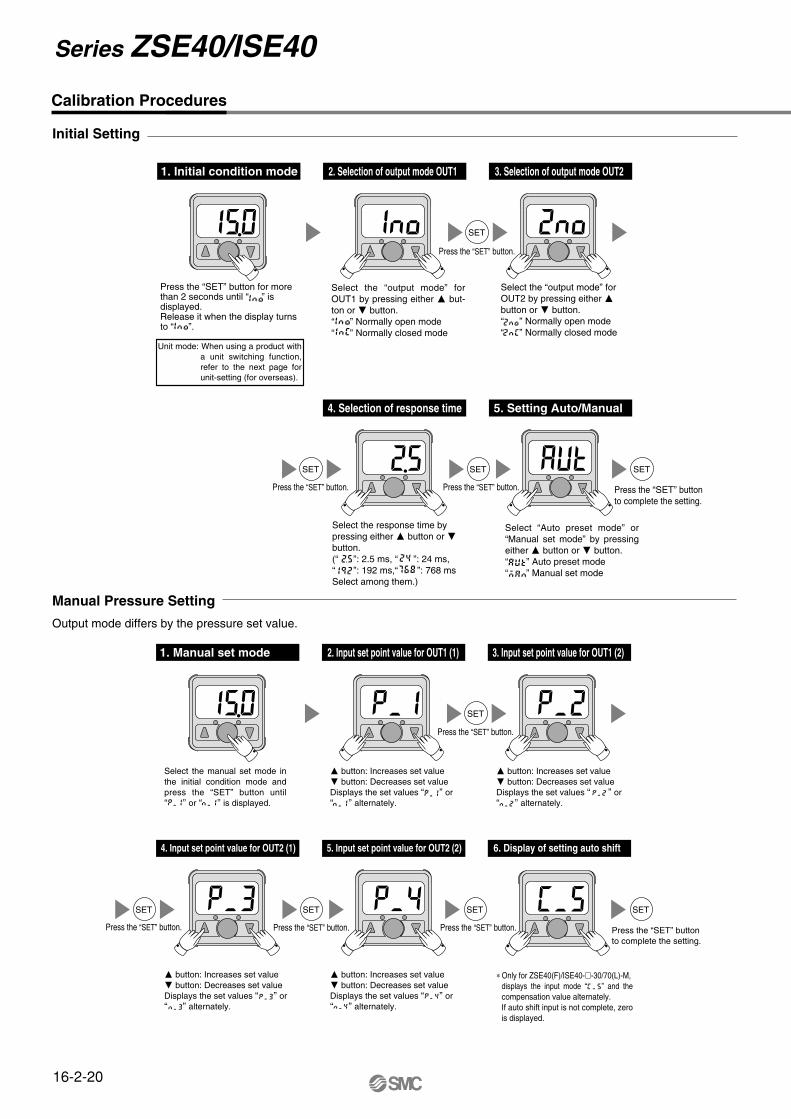
Select the response time by pressing either button or button.(“ ”: 2.5 ms, “ ”: 24 ms,“ ”: 192 ms,“ ”: 768 msSelect among them.)
Press the “SET” button for more than 2 seconds until “ ” is displayed.Release it when the display turns to “ ”.
Calibration Procedures
Initial Setting
Unit mode: When using a product with a unit switching function, refer to the next page for unit-setting (for overseas).
1. Initial condition mode 2. Selection of output mode OUT1 3. Selection of output mode OUT2
SET
Press the “SET” button.
Press the “SET” button.
Press the “SET” button.
4. Selection of response time 5. Setting Auto/Manual
Press the “SET” buttonto complete the setting.
SET SET SET
Select the “output mode” for OUT1 by pressing either but-ton or button.“ ” Normally open mode“ ” Normally closed mode
Select “Auto preset mode” or “Manual set mode” by pressing either button or button. “ ” Auto preset mode“ ” Manual set mode
Select the “output mode” for OUT2 by pressing either button or button.“ ” Normally open mode“ ” Normally closed mode
button: Increases set value button: Decreases set valueDisplays the set values “ ” or “ ” alternately.
∗ Only for ZSE40(F)/ISE40--30/70(L)-M,displays the input mode “ ” and the compensation value alternately.If auto shift input is not complete, zero is displayed.
Select the manual set mode in the initial condition mode and press the “SET” button until “ ” or “ ” is displayed.
Manual Pressure Setting
Output mode differs by the pressure set value.
Press the “SET” button.
1. Manual set mode 2. Input set point value for OUT1 (1) 3. Input set point value for OUT1 (2)
SET
Press the “SET” button. Press the “SET” button. Press the “SET” button.
4. Input set point value for OUT2 (1) 5. Input set point value for OUT2 (2)
SET SET SET
6. Display of setting auto shift
Press the “SET” buttonto complete the setting.
SET
button: Increases set value button: Decreases set valueDisplays the set values “ ” or “ ” alternately.
button: Increases set value button: Decreases set valueDisplays the set values “ ” or “ ” alternately.
button: Increases set value button: Decreases set valueDisplays the set values “ ” or “ ” alternately.
16-2-20
Series ZSE40/ISE40
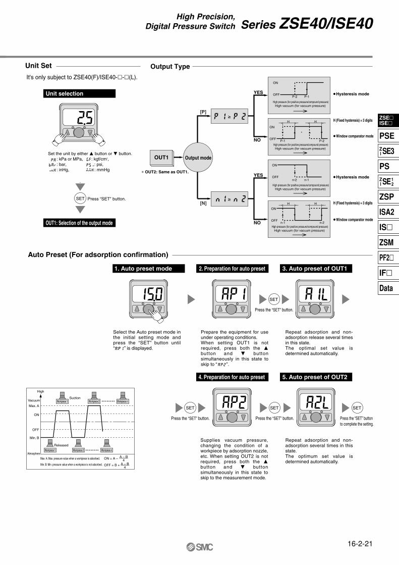
Prepare the equipment for use under operating conditions.When setting OUT1 is not required, press both the button and button simultaneously in this state to skip to “ ”.
Select the Auto preset mode in the initial setting mode and press the “SET” button until “ ” is displayed.
Auto Preset (For adsorption confirmation)
Workpiece 1 Workpiece 2
Workpiece 1 Workpiece 2 Workpiece n
ON = A –
OFF = B +
A – B4
A – B4
Workpiece n
High
Vacuum
Max. A
ON
OFF
Min. B
Atmosphere
Suction
Released
Max. A: Max. pressure value when a workpiece is adsorbed.
Min. B: Min. pressure value when a workpiece is not adsorbed.
Press the “SET” button.
1. Auto preset mode 2. Preparation for auto preset 3. Auto preset of OUT1
SET
Press the “SET” button.
4. Preparation for auto preset
Press the “SET” button.
5. Auto preset of OUT2
Press the “SET” buttonto complete the setting.
SET SET SET
Repeat adsorption and non-adsorption release several times in this state.The optimal set value is determined automatically.
Supplies vacuum pressure, changing the condition of a workpiece by adsorption nozzle, etc. When setting OUT2 is not required, press both the button and button simultaneously in this state to skip to the measurement mode.
Repeat adsorption and non-adsorption several times in this state.The optimum set value is determined automatically.
Unit Set
YES
NO
YES
NO
[P]
[N]
OUT1 Output mode
≥
≥
P-1P-2
P-2
n-1n-2
n-1 n-2
HH
HH H (Fixed hysteresis) = 3 digits
H (Fixed hysteresis) = 3 digits
∗ OUT2: Same as OUT1.
OFF
ON
High pressure (for positive pressure/compound pressure)High vacuum (for vacuum pressure)
High pressure (for positive pressure/compound pressure)High vacuum (for vacuum pressure)
High pressure (for positive pressure/compound pressure)High vacuum (for vacuum pressure)
High pressure (for positive pressure/compound pressure)High vacuum (for vacuum pressure)
OFF
ON
OFF
ON
OFF
ON
Window comparator mode
Hysteresis mode
Window comparator mode
Output Type
P-1
Unit selection
OUT1: Selection of the output mode
Press “SET” button.SET
It's only subject to ZSE40(F)/ISE40--(L).
Set the unit by either button or button. : kPa or MPa, : kgf/cm2,: bar, : psi, : inHg, : mmHg
Hysteresis mode
16-2-21
ZSEISE
PSEZI SE3
PSZI SE1
2
ZSP
ISA2
IS
ZSM
PF2
IF
Data
Series ZSE40/ISE40High Precision,
Digital Pressure Switch
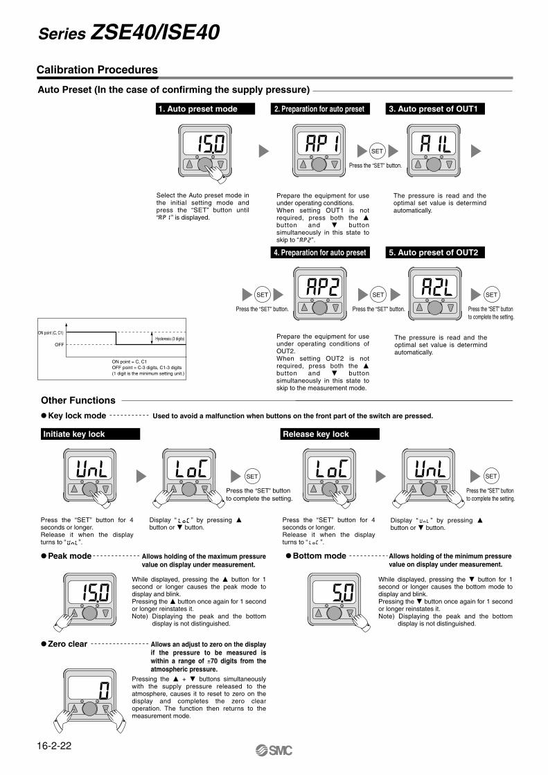
Prepare the equipment for use under operating conditions. When setting OUT1 is not required, press both the button and button simultaneously in this state to skip to “ ”.
Select the Auto preset mode in the initial setting mode and press the “SET” button until “ ” is displayed.
Auto Preset (In the case of confirming the supply pressure)
ON point = C, C1OFF point = C-3 digits, C1-3 digits(1 digit is the minimum setting unit.)
ON point (C, C1)
OFFHysteresis (3 digits)
Press the “SET” button.
1. Auto preset mode 2. Preparation for auto preset 3. Auto preset of OUT1
SET
Press the “SET” button.
4. Preparation for auto preset
Press the “SET” button.
5. Auto preset of OUT2
SET SET SET
Prepare the equipment for use under operating conditions of OUT2.When setting OUT2 is not required, press both the button and button simultaneously in this state to skip to the measurement mode.
The pressure is read and the optimal set value is determind automatically.
The pressure is read and the optimal set value is determind automatically.
Press the “SET” button for 4 seconds or longer.Release it when the display turns to “ ”.
Press the “SET” button for 4 seconds or longer.Release it when the display turns to “ ”.
Display “ ” by pressing button or button.
Display “ ” by pressing button or button.
Calibration Procedures
Other Functions
Initiate key lock
Key lock mode
Release key lock
SET SET
Peak mode
Used to avoid a malfunction when buttons on the front part of the switch are pressed.
Bottom mode
Zero clear
While displayed, pressing the button for 1 second or longer causes the peak mode to display and blink.Pressing the button once again for 1 second or longer reinstates it.Note) Displaying the peak and the bottom
display is not distinguished.
Pressing the + buttons simultaneously with the supply pressure released to the atmosphere, causes it to reset to zero on the display and completes the zero clear operation. The function then returns to the measurement mode.
While displayed, pressing the button for 1 second or longer causes the bottom mode to display and blink.Pressing the button once again for 1 second or longer reinstates it.Note) Displaying the peak and the bottom
display is not distinguished.
Allows an adjust to zero on the display if the pressure to be measured is within a range of ±70 digits from the atmospheric pressure.
Press the “SET” button to complete the setting.
Press the “SET” button to complete the setting.
Press the “SET” button to complete the setting.
Allows holding of the maximum pressure value on display under measurement.
Allows holding of the minimum pressure value on display under measurement.
16-2-22
Series ZSE40/ISE40

Dimensions
ZSE40(F)/ISE40-01 T1
MPa
OUT2OUT1
SET
Atmosphericrelease port
30
30
600
(300
0)
Lead
wire
leng
th
ø3.5
18.3
5 6.4 2-M3 x 0.5 thread depth 4
M5 x 0.8 thread depth 5
Wid
th a
cros
s fla
ts12
20
20
01: R 1/8T1: NPT 1/8
7.8
1.5
4.5
3014
2.5
15.2
10.7
2.6
7
12.4
ZSE40(F)/ISE40-W1
MPa
OUT2OUT1
SET
30
30
600
(300
0)
Lead
wire
leng
th
Atmosphericrelease port
719
18.3
5
ø3.5
6.4
Rc 1/8
2-M4 x 0.7thread depth 4
20
20
6.5R
Rc 1/812
42
4
10.715
.2
30
2.5
6
7.8
2.6
712.4
∗ For splash proof use (IP65), insert an air tube into the atmospheric release port.(Refer to “Precautions” on page 16-2-24 for details.)
∗ For splash proof use (IP65), insert an air tube into the atmospheric release port.(Refer to “Precautions” on page 16-2-24 for details.)
16-2-23
ZSEISE
PSEZI SE3
PSZI SE1
2
ZSP
ISA2
IS
ZSM
PF2
IF
Data
Series ZSE40/ISE40High Precision,
Digital Pressure Switch
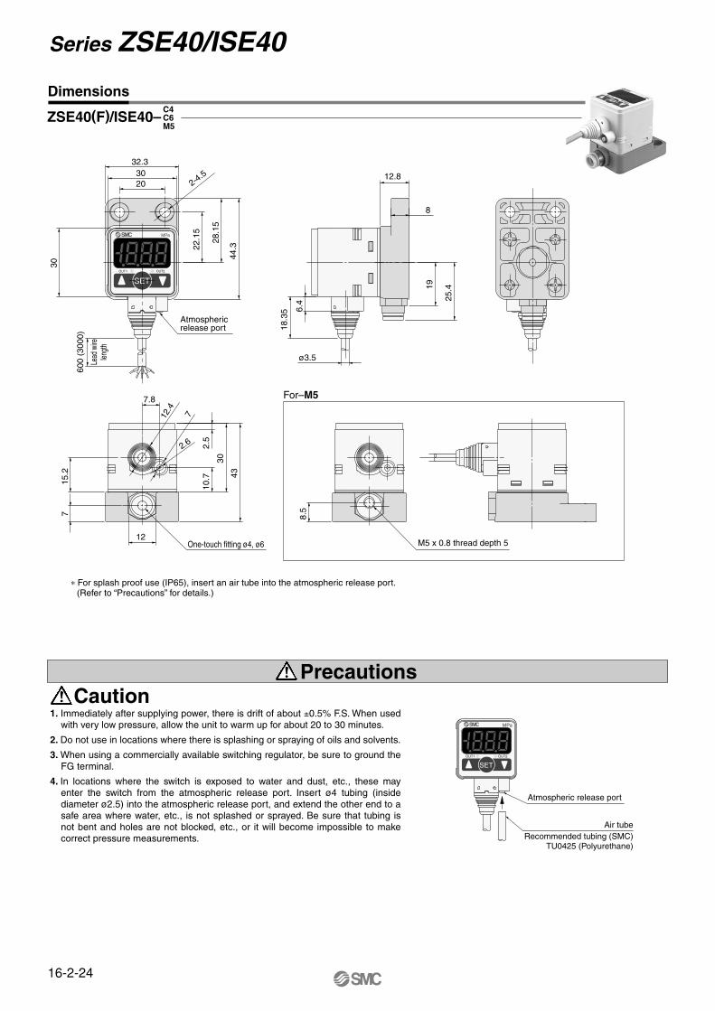
Dimensions
Caution1. Immediately after supplying power, there is drift of about ±0.5% F.S. When used
with very low pressure, allow the unit to warm up for about 20 to 30 minutes.
2. Do not use in locations where there is splashing or spraying of oils and solvents.
3. When using a commercially available switching regulator, be sure to ground the FG terminal.
4. In locations where the switch is exposed to water and dust, etc., these may enter the switch from the atmospheric release port. Insert ø4 tubing (inside diameter ø2.5) into the atmospheric release port, and extend the other end to a safe area where water, etc., is not splashed or sprayed. Be sure that tubing is not bent and holes are not blocked, etc., or it will become impossible to make correct pressure measurements.
Air tubeRecommended tubing (SMC)
TU0425 (Polyurethane)
Atmospheric release port
For–M5
ZSE40(F)/ISE40–C4C6M5
Precautions
SETOUT1 OUT2
MPa
600
(300
0)
Lead
wire
lengt
h
32.3
44.3
28.1
5
22.1
52030
30
2-4.5
Atmosphericrelease port
6.4 25
.4
12.8
8
ø3.5
18.3
5
19
One-touch fitting ø4, ø6
7
12
43
2.5
30
15.2
10.7
7.8
2.6
712.4
M5 x 0.8 thread depth 5
8.5
MPa
OUT2OUT1
SET
∗ For splash proof use (IP65), insert an air tube into the atmospheric release port.(Refer to “Precautions” for details.)
16-2-24
Series ZSE40/ISE40
Safety Instructions
These safety instructions are intended to prevent a hazardous situation and/or equipment damage. These instructions indicate the level of potential hazard by labels of "Caution", "Warning" or "Danger". To ensure safety, be sure to observe ISO 4414 Note 1), JIS B 8370 Note 2) and other safety practices.
1. The compatibility of pneumatic equipment is the responsibility of the person who designs the pneumatic system or decides its specifications.Since the products specified here are used in various operating conditions, their compatibility for the specific pneumatic system must be based on specifications or after analysis and/or tests to meet your specific requirements. The expected performance and safety assurance will be the responsibility of the person who has determined the compatibility of the system. This person should continuously review the suitability of all items specified, referring to the latest catalog information with a view to giving due consideration to any possibility of equipment failure when configuring a system.
2. Only trained personnel should operate pneumatically operated machinery and equipment.Compressed air can be dangerous if an operator is unfamiliar with it. Assembly, handling or repair of pneumatic systems should be performed by trained and experienced operators.
3. Do not service machinery/equipment or attempt to remove components until safety is confirmed.1. Inspection and maintenance of machinery/equipment should only be performed once measures to
prevent falling or runaway of the driver objects have been confirmed. 2. When equipment is to be removed, confirm the safety process as mentioned above. Cut the supply
pressure for this equipment and exhaust all residual compressed air in the system.3. Before machinery/equipment is restarted, take measures to prevent shooting-out of cylinder piston
rod, etc.
4. Contact SMC if the product is to be used in any of the following conditions:1. Conditions and environments beyond the given specifications, or if product is used outdoors.2. Installation on equipment in conjunction with atomic energy, railway, air navigation, vehicles,
medical equipment, food and beverages, recreation equipment, emergency stop circuits, clutch and brake circuits in press applications, or safety equipment.
3. An application which has the possibility of having negative effects on people, property, or animals, requiring special safety analysis.
Note 1) ISO 4414: Pneumatic fluid power--General rules relating to systems.
Note 2) JIS B 8370: General Rules for Pneumatic Equipment
Warning
Caution : Operator error could result in injury or equipment damage.
Warning : Operator error could result in serious injury or loss of life.
Danger : In extreme conditions, there is a possible result of serious injury or loss of life.
16-14-3
1. Confirm the specifications.Products represented in this catalog are designed for use in compressed air appllications only (including vacuum), unless otherwise indicated.Do not use the product outside their design parameters.Please contact SMC when using the products in applications other than compressed air (including vacuum).
4. Use clean airIf the compressed air supply is contaminated with chemicals, cynthetic materials, corrosive gas, etc., it may lead to break down or malfunction.
Selection
Mounting
Piping
Air Supply
Maintenance
Operating Environment
Warning
1. Instruction manualInstall the products and operate them only after reading the instruction manual carefully and understanding its contents. Also keep the manual where it can be referred to as necessary.
2. Securing the space for maintenanceWhen installing the products, please allow access for maintenance.
3. Tightening torqueWhen installing the products, please follow the listed torque specifications.
Warning
1. Do not use in environments where the product is directly exposed to corrosive gases, chemicals, salt water, water or steam.
2. Do not expose the product to direct sunlight for an extended period of time.
3. Do not use in a place subject to heavy vibrations and/or shocks.
4. Do not mount the product in locations where it is exposed to radiant heat.
Warning
1. Maintenance procedures are outlined in the operation manual.Not following proper procedures could cause the product to malfunction and could lead to damage to the equipment or machine.
2. Maintenance workIf handled improperly, compressed air can be dangerous.Assembly, handling and repair of pneumatic systems should be performed by qualified personnel only.
3. Drain flushingRemove drainage from air filters regularly. (Refer to the specifications.)
4. Shut-down before maintenanceBefore attempting any kind of maintenance make sure the supply pressure is shut of and all residual air pressure is released from the system to be worked on.
5. Start-up after maintenance and inspectionApply operating pressure and power to the equipment and check for proper operation and possible air leaks. If operation is abnormal, please verify product set-up parameters.
6. Do not make any modifications to be product.Do not take the product apart.
Warning
1. Before pipingMake sure that all debris, cutting oil, dust, etc, are removed from the piping.
2. Wrapping of pipe tapeWhen screwing piping or fittings into ports, ensure that chips from the pipe threads or sealing material do not get inside the piping. Also, when the pipe tape is used, leave 1.5 to 2 thread ridges exposed at the end of the threads.
Caution
1. Operating fluidPlease consult with SMC when using the product in applications other than compressed air (including vacuum).Regarding products for general fluid, please ask SMC about applicable fluids.
2. Install an air dryer, aftercooler, etc.Excessive condensate in a compressed air system may cause valves and other pneumatic equipment to malfunction.Installation of an air dryer, after cooler etc. is recommended.
3. Drain flushingIf condensate in the drain bowl is not emptied on a regular basis, the bowl will over flow and allow the condensate to enter the compressed air lines.If the drain bowl is difficult to check and remove, it is recommended that a drain bowl with the auto-drain option be installed.For compressed air quality, refer to “Air Preparation Equipment” catalog.
Warning
Common PrecautionsBe sure to read before handling.For detailed precautions on every series, refer to main text.
16-14-4
Quality Assurance Information(ISO 9001, ISO 14001)
Reliable quality of products in the global market
To enable our customers throughout the world to use our products with even greater confidence, SMC has obtained certification for international standards “ISO 9001” and “ISO 14001”, and created a complete structure for quality assurance and environmental controls. SMC products pursue to meet its customers’ expectations while also considering company’s contribution in society.
This is an international standard for quality control and quality assurance. SMC has obtained a large number of certifications in Japan and overseas, providing assurance to our customers throughout the world.
Quality management system
ISO 9001
This is an international standard related to environmental management systems and environmental inspections. While promoting environmentally friendly automation technology, SMC is also making diligent efforts to preserve the environment.
Environmental management system
ISO 14001
Sales coordination
Production
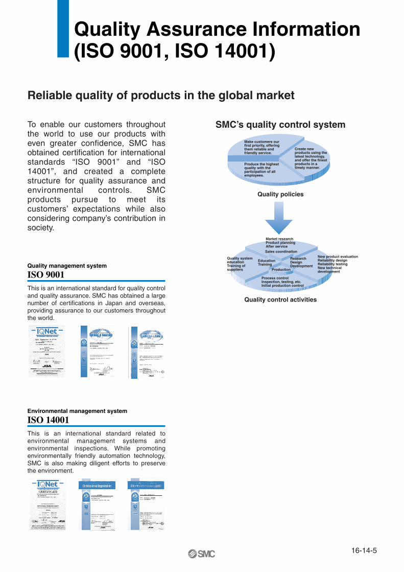
Make customers our first priority, offering them reliable and friendly service.
Market researchProduct planningAfter service
Process controlInspection, testing, etc.Initial production control
Quality system educationTraining of suppliers
New product evaluationReliability designReliability testingNew technical development
EducationTraining
ResearchDesignDevelopment
Produce the highest quality with the participation of all employees.
Create new products using the latest technology, and offer the finest products in a timely manner.
SMC’s quality control system
Quality policies
Quality control activities
16-14-5
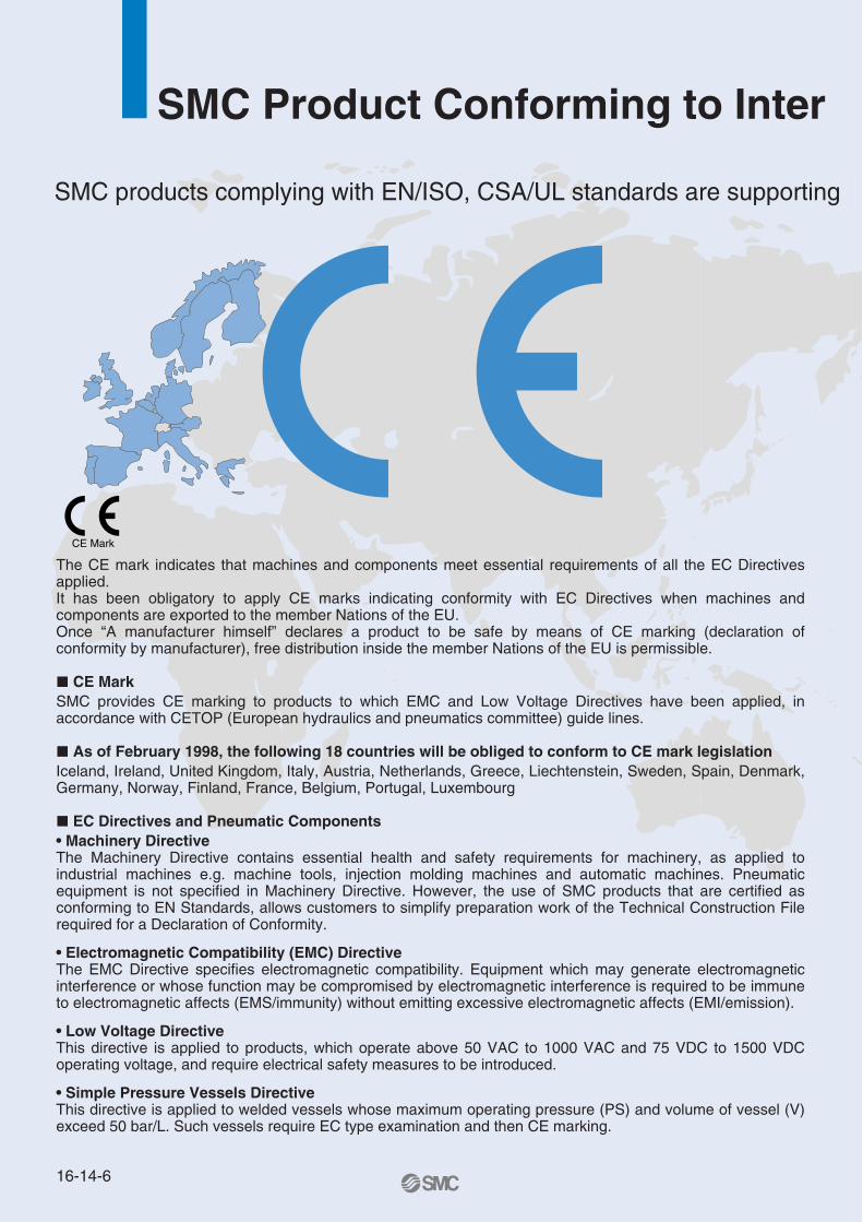
CE Mark
SMC Product Conforming to Inter
SMC products complying with EN/ISO, CSA/UL standards are supporting
The CE mark indicates that machines and components meet essential requirements of all the EC Directives applied.It has been obligatory to apply CE marks indicating conformity with EC Directives when machines and components are exported to the member Nations of the EU. Once “A manufacturer himself” declares a product to be safe by means of CE marking (declaration of conformity by manufacturer), free distribution inside the member Nations of the EU is permissible.
CE MarkSMC provides CE marking to products to which EMC and Low Voltage Directives have been applied, in accordance with CETOP (European hydraulics and pneumatics committee) guide lines.
As of February 1998, the following 18 countries will be obliged to conform to CE mark legislationIceland, Ireland, United Kingdom, Italy, Austria, Netherlands, Greece, Liechtenstein, Sweden, Spain, Denmark, Germany, Norway, Finland, France, Belgium, Portugal, Luxembourg
EC Directives and Pneumatic Components• Machinery DirectiveThe Machinery Directive contains essential health and safety requirements for machinery, as applied to industrial machines e.g. machine tools, injection molding machines and automatic machines. Pneumatic equipment is not specified in Machinery Directive. However, the use of SMC products that are certified as conforming to EN Standards, allows customers to simplify preparation work of the Technical Construction File required for a Declaration of Conformity.
• Electromagnetic Compatibility (EMC) DirectiveThe EMC Directive specifies electromagnetic compatibility. Equipment which may generate electromagnetic interference or whose function may be compromised by electromagnetic interference is required to be immune to electromagnetic affects (EMS/immunity) without emitting excessive electromagnetic affects (EMI/emission).
• Low Voltage DirectiveThis directive is applied to products, which operate above 50 VAC to 1000 VAC and 75 VDC to 1500 VDC operating voltage, and require electrical safety measures to be introduced.
• Simple Pressure Vessels DirectiveThis directive is applied to welded vessels whose maximum operating pressure (PS) and volume of vessel (V) exceed 50 bar/L. Such vessels require EC type examination and then CE marking.
16-14-6
http://www.smcworld.com
you to comply with EC directives and CSA/UL standards.
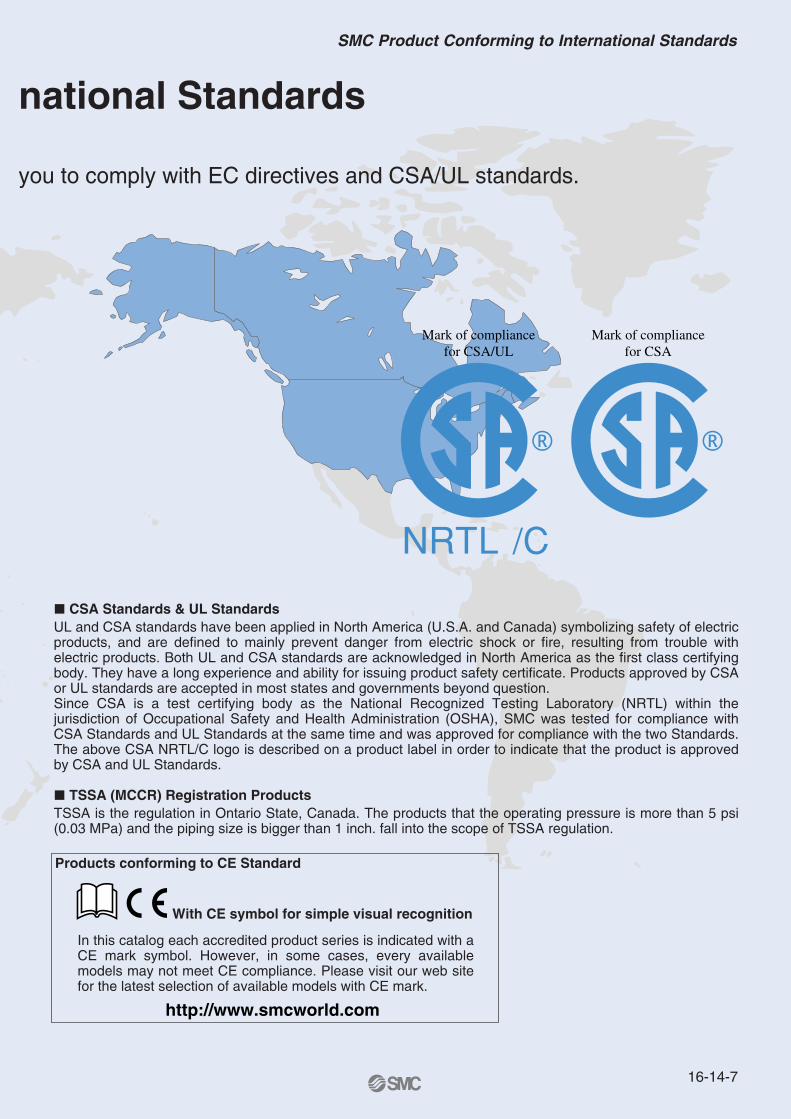
CSA Standards & UL StandardsUL and CSA standards have been applied in North America (U.S.A. and Canada) symbolizing safety of electric products, and are defined to mainly prevent danger from electric shock or fire, resulting from trouble with electric products. Both UL and CSA standards are acknowledged in North America as the first class certifying body. They have a long experience and ability for issuing product safety certificate. Products approved by CSA or UL standards are accepted in most states and governments beyond question.Since CSA is a test certifying body as the National Recognized Testing Laboratory (NRTL) within the jurisdiction of Occupational Safety and Health Administration (OSHA), SMC was tested for compliance with CSA Standards and UL Standards at the same time and was approved for compliance with the two Standards. The above CSA NRTL/C logo is described on a product label in order to indicate that the product is approved by CSA and UL Standards.
TSSA (MCCR) Registration Products TSSA is the regulation in Ontario State, Canada. The products that the operating pressure is more than 5 psi (0.03 MPa) and the piping size is bigger than 1 inch. fall into the scope of TSSA regulation.
Products conforming to CE Standard
With CE symbol for simple visual recognition
In this catalog each accredited product series is indicated with a CE mark symbol. However, in some cases, every available models may not meet CE compliance. Please visit our web site for the latest selection of available models with CE mark.
Mark of compliance for CSA
Mark of compliance for CSA/UL
national Standards
16-14-7
SMC Product Conforming to International Standards
America EuropeU.S.A. SMC Corporation of America3011 North Franklin Road Indianapolis, IN 46226, U.S.A.TEL: 317-899-4440 FAX: 317-899-3102
CANADA SMC Pneumatics (Canada) Ltd.6768 Financial Drive Mississauga, Ontario, L5N 7J6 CanadaTEL: 905-812-0400 FAX: 905-812-8686
MEXICO SMC Corporation (Mexico), S.A. DE C.V.Carr. Silao-Trejo K.M. 2.5 S/N, Predio San Jose del DuranzoC.P. 36100, Silao, Gto., MexicoTEL: 472-72-2-55-00 FAX: 472-72-2-59-44/2-59-46
CHILE SMC Pneumatics (Chile) S.A.Av. La Montaña 1,115 km. 16,5 P. Norte ParqueIndustrial Valle Grande, Lampa Santiago, ChileTEL: 02-270-8600 FAX: 02-270-8601
ARGENTINA SMC Argentina S.A.Teodoro Garcia 3860 (1427) Buenos Aires, ArgentinaTEL: 011-4555-5762 FAX: 011-4555-5762
BOLIVIA SMC Pneumatics Bolivia S.R.L.Avenida Beni Numero 4665Santa Cruz de la Sierra-Casilla de Correo 2281, BoliviaTEL: 591-3-3428383 FAX: 591-3-3449900
VENEZUELA SMC Neumatica Venezuela S.A. Apartado 40152, Avenida Nueva Granada, Edificio Wanlac,Local 5, Caracas 1040-A, VenezuelaTEL: 2-632-1310 FAX: 2-632-3871
PERU (Distributor) IMPECO Automatizacion Industrial S.A. AV. Canevaro 752, Lince, Lima, PeruTEL: 1-471-6002 FAX: 1-471-0935
URUGUAY (Distributor) BAKO S.A. Galicia 1650 esq. Gaboto C.P. 11200, Montevideo, UruguayTEL: 2-401-6603 FAX: 2-409-4306
BRAZIL SMC Pneumaticos Do Brasil Ltda.Rua. Dra. Maria Fidelis, nr. 130, Jardim Piraporinha-Diadema-S.P. CEP: 09950-350, BrasilTEL: 11-4051-1177 FAX: 11-4071-6636
COLOMBIA (Distributor) Airmatic Ltda.Calle 18 69-05 Apart. Aereo 081045 Santa Fe de Bogotá, ColombiaTEL: 1-424-9240 FAX: 1-424-9260
U.K. SMC Pneumatics (U.K.) Ltd.Vincent Avenue, Crownhill, Milton Keynes, MK8 0AN, Backinghamshire, U.K.TEL: 01908-563888 FAX: 01908-561185
GERMANY SMC Pneumatik GmbHBoschring 13-15 D-63329 Egelsbach, GermanyTEL: 06103-4020 FAX: 06103-402139
ITALY SMC Italia S.p.A.Via Garibaldi 62 I-20061 Carugate Milano, ItalyTEL: 02-9271365 FAX: 02-9271365
FRANCE SMC Pneumatique S.A.1 Boulevard de Strasbourg, Parc Gustave Eiffel, Bussy Saint Georges, F-77600Marne La Vallee Cedex 3 FranceTEL: 01-64-76-10-00 FAX: 01-64-76-10-10
SWEDEN SMC Pneumatics Sweden ABEkhagsvägen 29-31, S-141 05 Huddinge, SwedenTEL: 08-603-07-00 FAX: 08-603-07-10
SWITZERLAND SMC Pneumatik AGDorfstrasse 7, Postfach 117, CH-8484 Weisslingen, SwitzerlandTEL: 052-396-3131 FAX: 052-396-3191
AUSTRIA SMC Pneumatik GmbH (Austria)Girakstrasse 8, A-2100 Korneuburg, AustriaTEL: 0-2262-6228-0 FAX: 0-2262-62285
SPAIN SMC España, S.A.Zuazobidea 14 Pol. Ind. Júndiz 01015 Vitoria, SpainTEL: 945-184-100 FAX: 945-184-510
IRELAND SMC Pneumatics (Ireland) Ltd.2002 Citywest Business Campus, Naas Road, Saggart, Co. Dublin, IrelandTEL: 01-403-9000 FAX: 01-466-0385
NETHERLANDS (Associated company) SMC Pneumatics BVDe Ruyterkade 120, NL-1011 AB Amsterdam, NetherlandsTEL: 020-5318888 FAX: 020-5318880
GREECE (Distributor) S.Parianopoulos S.A.7, Konstantinoupoleos Street 11855 Athens, GreeceTEL: 01-3426076 FAX: 01-3455578
DENMARK SMC Pneumatik A/SKnudsminde 4 B DK-8300Odder, DenmarkTEL: 70252900 FAX: 70252901
SMC’s Global Service Network
16-14-20

EuropeFINLAND SMC Pneumatics Finland OYPL72, Tiistinniityntie 4, SF-02231 ESP00, FinlandTEL: 09-8595-80 FAX: 09-8595-8595
NORWAY SMC Pneumatics Norway A/SVollsveien 13C, Granfoss Næringspark N-1366 LYSAKER, NorwayTEL: 67-12-90-20 FAX: 67-12-90-21
BELGIUM (Distributor) SMC Pneumatics N.V./S.A.Nijverheidsstraat 20 B-2160 Wommelgem BelguimTEL: 03-355-1464 FAX: 03-355-1466
POLAND SMC Industrial Automation Polska Sp.z.o.o.ul. Konstruktorska 11A, PL-02-673 Warszawa, PolandTEL: 022-548-5085 FAX: 022-548-5087
TURKEY (Distributor) Entek Pnömatik San.ve Tic. Ltd. StiPerpa Tic. Merkezi Kat:11 No.1625 80270 Okmeydani Istanbul, TürkiyeTEL: 0212-221-1512 FAX: 0212-221-1519
RUSSIA SMC Pneumatik LLC.36/40 Sredny prospect V.O. St. Petersburg 199004, RussiaTEL: 812-118-5445 FAX: 812-118-5449
CZECH SMC Industrial Automation CZ s.r.o.Hudcova 78a, CZ-61200 Brno, Czech RepublicTEL: 05-4121-8034 FAX: 05-4121-8034
HUNGARY SMC Hungary Ipari Automatizálási kft.Budafoki ut 107-113 1117 BudapestTEL: 01-371-1343 FAX: 01-371-1344
ROMANIA SMC Romania S.r.l.Str. Frunzei, Nr. 29, Sector 2, Bucharest, RomaniaTEL: 01-3205111 FAX: 01-3261489
SLOVAKIA SMC Priemyselná automatizáciá, s.r.oNova 3, SK-83103 BratislavaTEL: 02-4445-6725 FAX: 02-4445-6028
SLOVENIA SMC Industrijska Avtomatilca d.o.o.Grajski trg 15, SLO- 8360 Zuzemberk, SloveniaTEL: 07388-5240 FAX: 07388-5249
SOUTH AFRICA (Distributor) Hyflo Southern Africa (Pty.) Ltd.P.O.Box 240 Paardeneiland 7420 South AfricaTEL: 021-511-7021 FAX: 021-511-4456
EGYPT (Distributor) Saadani Trading & Ind. Services15 Sebaai Street, Miami 21411 Alexandria, EgyptTEL: 3-548-50-34 FAX: 3-548-50-34
Oceania/AsiaAUSTRALIA SMC Pneumatics (Australia) Pty.Ltd.14-18 Hudson Avenue Castle Hill NSW 2154, AustraliaTEL: 02-9354-8222 FAX: 02-9894-5719
NEW ZEALAND SMC Pneumatics (New Zealand) Ltd.8C Sylvia Park Road Mt.Wellington Auckland, New ZealandTEL: 09-573-7007 FAX: 09-573-7002
TAIWAN SMC Pneumatics (Taiwan) Co.,Ltd.17, Lane 205, Nansan Rd., Sec.2, Luzhu-Hsiang, Taoyuan-Hsien, TAIWANTEL: 03-322-3443 FAX: 03-322-3387
HONG KONG SMC Pneumatics (Hong Kong) Ltd. 29/F, Clifford Centre, 778-784 Cheung, Sha Wan Road, Lai Chi Kok, Kowloon,Hong KongTEL: 2744-0121 FAX: 2785-1314
SINGAPORE SMC Pneumatics (S.E.A.) Pte. Ltd.89 Tuas Avenue 1, Jurong Singapore 639520TEL: 6861-0888 FAX: 6861-1889
PHILIPPINES SHOKETSU SMC CorporationUnit 201 Common Goal Tower, Madrigal Business Park,Ayala Alabang Muntinlupa, PhilippinesTEL: 02-8090565 FAX: 02-8090586
MALAYSIA SMC Pneumatics (S.E.A.) Sdn. Bhd.Lot 36 Jalan Delima1/1, Subang Hi-Tech Industrial Park, Batu 3 40000 Shah AlamSelangor, MalaysiaTEL: 03-56350590 FAX: 03-56350602
SOUTH KOREA SMC Pneumatics Korea Co., Ltd.Woolim e-BIZ Center (Room 1008), 170-5, Guro-Dong, Guro-Gu,Seoul, 152-050, South KoreaTEL: 02-3219-0700 FAX: 02-3219-0702
CHINA SMC (China) Co., Ltd.7 Wan Yuan St. Beijing Economic & Technological Development Zone 100176, China TEL: 010-67882111 FAX: 010-67881837
THAILAND SMC Thailand Ltd.134/6 Moo 5, Tiwanon Road, Bangkadi, Amphur Muang, Patumthani 12000, ThailandTEL: 02-963-7099 FAX: 02-501-2937
INDIA SMC Pneumatics (India) Pvt. Ltd.D-107 to 112, Phase-2, Extension, Noida, Dist. Gautaim Budh Nagar,U.P. 201 305, IndiaTEL: (0120)-4568730 FAX: 0120-4568933
INDONESIA (Distributor) P.T. Riyadi Putera MakmurJalan Hayam Wuruk Komplek Glodok Jaya No. 27-28 Jakarta 11180 IndonesiaTEL: 021-625 5548 FAX: 021-625 5888
PAKISTAN (Distributor) Jubilee CorporationFirst Floor Mercantile Centre, Newton Road Near Boulton Market P.O. Box 6165 Karachi 74000 PakistanTEL: 021-243-9070/8449 FAX: 021-241-4589
ISRAEL (Distributor) Baccara Automation ControlKvutzat Geva 18915 IsraelTEL: 04-653-5960 FAX: 04-653-1445
SAUDI ARABIA (Distributor) Assaggaff Trading Est.P.O. Box 3385 Al-Amir Majed Street, Jeddah-21471, Saudi ArabiaTEL: 02-6761574 FAX: 02-6708173
16-14-21
SMC’s Global Service Network